box way series cnc lathes - indumach · box way series cnc lathes ... finish programming without...
TRANSCRIPT

FBL-300/L/MCFBL-360/L/MCFBL-460/L/MCBox Way Series CNC Lathes

Contents
01
02Controller
03FBL-300/360/L/MC SeriesConstruction & Spindle Transmission System
04FBL-300/L System Diagram
05FBL-300/360/L/MC System Diagram
08FBL-460System Diagram
Box Way SeriesCNC LathesFBL-300/L/MCFBL-360/L/MCFBL-460/L/MC

02
09FBL-460/L/MCSystem Diagram
11Spindle Torque Diagram
13Specifications
12Standard & Optional Accessories
Uses a 10.4" screen for easy operation. Optional Shop Turn function with integrated operating system. Finish programming without having to use G-code.
SIEMENSFANUC
Controller
• 2 window view dynamic simulation
• 3D finished part simulation (opt.)
• 3D section view (opt.)
Manual Guide i (opt.)Conversational editing with 3D simulation available.
Polar Coordinate Interpolation (For C-axis)
Cylindrical Interpolation
Features• Sturdy box way model capable of
low speed heavy-duty machining.
• Armed with the latest Fanuc 0i control, high resolution LCD screen, and multi-functional interface, for the best possible operating environment.
• High rigidity box way with scrapped slide way and precision oil network design for superb transmission efficiency.
• 45-degree slant bed structure with a low center of gravity, for enhanced machining accuracy.
03
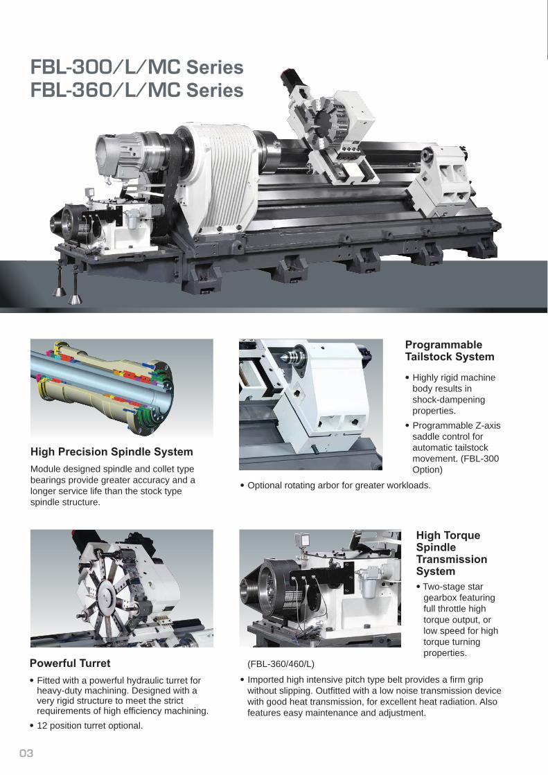
FBL-300/L/MC SeriesFBL-360/L/MC Series
High Precision Spindle System Module designed spindle and collet type bearings provide greater accuracy and a longer service life than the stock type spindle structure.
Powerful Turret• Fitted with a powerful hydraulic turret for
heavy-duty machining. Designed with a very rigid structure to meet the strict requirements of high efficiency machining.
• 12 position turret optional.
ProgrammableTailstock System
• Highly rigid machine body results in shock-dampening properties.
• Programmable Z-axis saddle control for automatic tailstock movement. (FBL-300 Option)
• Optional rotating arbor for greater workloads.
High TorqueSpindle TransmissionSystem• Two-stage star
gearbox featuring full throttle high torque output, or low speed for high torque turning properties.
(FBL-360/460/L)
• Imported high intensive pitch type belt provides a firm grip without slipping. Outfitted with a low noise transmission device with good heat transmission, for excellent heat radiation. Also features easy maintenance and adjustment.

04
FBL-300/L System Diagram
FBL-300 Tooling System
Optional 12 Tools
ø261
ø211
ø161ø210
ø229
ø229
ø40
ø233ø310
ø271
40
ø410ø500
X-Axis Travel 290440220 255 35
40
FBL-300 Tool Interference
Standard 10 Tools +10” Chuck
440
220 255 35
40
ø286
ø291ø208
ø281
ø410ø500
ø325
40
25
ø308
X-Axis Travel 290
ø325
Face Tool & O.D. CuttingTool Holder
Face Tool & O.D. CuttingTool Holder
25O.D. & Face Tool
25I.D. & Face Tool
25O.D. & Face Tool
25O.D. & Face Tool
ø40 Boring Tool
Boring Tool
Boring Tool
Drill Pin
High Speed Drill
LS-250SV / LS-250H10 Position Tool Turret
Face Holder
Reducing Sleeves
Drill Sleeves
OP.
OP.
ø40 Boring Bar Holder
ø40Cover
Boring Bar Holder
MT#2MT#3
ø8 / ø10 / ø12 / ø16 / ø20 / ø25 / ø32
Taper Slice Mounting Block
Clamp Block
ø32 Boring Bar Holder
Unit: mm
Metric 8 mm10 mm12 mm16 mm20 mm25 mm32 mm40 mm50 mm
Imperial5/16”3/8”1/2”5/8”3/4”1”
1 1/4”1 9/16”
2”

05
FBL-300/360/L/MC System Diagram
NN TypeCollet Structure Design
ø130
ø88
196
46 594
79 111 747.5
550 Tailstock Stroke120113 43
50
137
7
40
255
10” C
HU
CK
290
X-A
xis
Trav
el
35
34
140
640Z-Axis Travel
FBL-300 Spindle Structure FBL-300 Machining Area
BMT 65FBL-300MC Tooling System
ER-32(ø2-ø20)
ET1-32(M2-M24)
25x25
25x25
ø8-ø40ø10-ø40ø12-ø40ø16-ø40ø20-ø40ø25-ø40ø32-ø40
MT3MT2
Collets for Tapping
Collets
Cover
Boring Bar Holder
Face Tool & O.D. Cutting Tool Holder
Face Holder
Radial Drill / Mill Unit
Axial Drill / Mill Unit
Metric 8 mm10 mm12 mm16 mm20 mm25 mm32 mm40 mm50 mm
Imperial5/16”3/8”1/2”5/8”3/4”1”
1 1/4”1 9/16”
2”
Unit: mm

06
Unit: mm
FBL-360 Spindle Structure
NN TypeCollet Structure Design
ø160
ø105
FBL-360 Tooling System
MountingBlock
LS-32010 Position Tool Turret
Face & I.D.Cutting
Face Holder
Boring Bar / Drill Holder
Boring Tool
Boring Bar Sleeve
ø8 / 10 / 12 / 16 / 20 / 25 / 32 / 40
ø20 / 25 / 32 / 40
FBL-360 Tool Interference
30
45
35
50 320
290
ø305
ø301
ø327
ø290 ø50
ø486
ø570
ø486
32mmFacing Tool
32mmFacing Tool
U-Drill
DrillDrill Socket
OP.U-DrillSocket
FBL-300MC Tool Interference FBL-300MC Machining Area
ø102
8
514
290
ø20
ø509
ø389
60 70
6
265 40 209290
81
ø389ø418
ø42
25238
290
ø210
ø229
ø602
640155
514
262
29060
38
26.740
119
55
2
60
101.5
125.9
113178
79105
780.877.6
130 550
576
Z-Axis Travel
Tailstock Base Stroke
X-A
xis
Trav
el
BMT 65 BMT 65
Spi
ndle
Nos
e
ø263
ø228ø225

07
FBL-300/360/L/MC System Diagram
FBL-360 Machining Area FBL-360L Machining Area
2100Z-Axis Travel
2026
2000Quill Stroke
319 120
Max. Cutting Length
285
35
320
X-A
xis
Trav
el
45
8
Tailstock Stroke
2300
290
30
137
145
820
820
8
214 120
137
305
30 25
320
290
45
295
320
40 40
Quill Stroke
Tailstock Base Stroke
Z-Axis Travel
X-A
xis
Trav
el
BMT 75FBL-360MC Tooling System
32x32
32x32
ø8-ø50ø10-ø50ø12-ø50ø16-ø50ø20-ø50ø25-ø50ø32-ø50ø40-ø50
MT3MT2
ER-40(ø3-ø26)
ET1-40(ø6-ø17)
Face Tool & O.D. CuttingTool Holder
O.D. & Face Tool
O.D. & Face Tool
Face Holder
Reducing Sleeves
Collets
Collets for Tapping
Cover
Boring Bar Holder
Clamp Block
Clamp Block
Radial Drill / Mill Unit
Axial Drill / Mill Unit
Metric 8 mm10 mm12 mm16 mm20 mm25 mm32 mm40 mm50 mm
Imperial5/16”3/8”1/2”5/8”3/4”1”
1 1/4”1 9/16”
2”
Unit: mm

Unit: mm
08
FBL-460 System Diagram
FBL-360MC Machining AreaFBL-360MC Tool Interference BMT 75 BMT 75
10
585
215
320
35
7015
4028320
ø550
ø600
ø651 ø72
6
ø198.3
60
98
7885
820
820
ø305
60
585
12"
95
10310
649
215
70
70
2
120122 51
214
108A2-8
74
160
5180 320
ø381 (15" Chuck)
Max. Cutting dia. ø570
Z-Axis Travel
Quill Stroke Tailstock Base Stroke
X-Axis
Trave
l26
0
104
FBL-460 Tooling System
Boring Bar/Drill Holder
U-DrillU-Drill Socket
Drill Socket(MT#)Drill
Facing ToolBoring Bar Sleeve
Facing Tool
Facing Tool Face & I.D. Cutting
Mounting Block
For Direct Mounting on Turret
10 / 12 Tool Turret
Clamp Block
OP.
ø50
32x32
32x32
ø40ø32
ø25ø20
32x32
MT.2MT.3MT.4
LS-320/LS-320SV
ø16
ø32ø25ø20
ø16
ø10
ø40ø12
ø8
Metric 8 mm10 mm12 mm16 mm20 mm25 mm32 mm40 mm50 mm
Imperial5/16”3/8”1/2”5/8”3/4”1”
1 1/4”1 9/16”
2”

FBL-460/L/MC System Diagram
09
FBL-460 Tool Interference-10T
35
360
ø327
ø290
50
ø301
ø305 30
45
330
ø385
ø650ø575
ø50
ø566
FBL-460 Tool Interference-12T
55
36050
615
ø535
ø610
ø51
ø344
ø253
ø288
ø265
ø268
45310
50
ø534
520
64
BMT 75FBL-460MC Tooling System
32x32
32x32
ø8-ø50ø10-ø50ø12-ø50ø16-ø50ø20-ø50ø25-ø50ø32-ø50ø40-ø50
MT3MT2
ER-40(ø3-ø26)
ET1-40(ø6-ø17)
Face Tool & O.D. CuttingTool Holder
O.D. & Face Tool
O.D. & Face Tool
Face Holder
Reducing Sleeves
Collets
Collets for Tapping
Cover
Boring Bar Holder
Clamp Block
Clamp Block
Radial Drill / Mill Unit
Axial Drill / Mill Unit
Metric 8 mm10 mm12 mm16 mm20 mm25 mm32 mm40 mm50 mm
Imperial5/16”3/8”1/2”5/8”3/4”1”
1 1/4”1 9/16”
2”
Unit: mm

Unit: mm
10
FBL-460 Machining Area
504533
030 35
325
360
757
184 120 820
8
820
55 765
279
224
694
1008
X-S
troke
Quill StrokeTailstock Stroke
Between Center
Max. Cutting Length
Z-Axis Stroke
FBL-460 Spindle Structure
ø160
ø220
NN TypeCollet Structure Design
FBL-460LMC Machining Area
418
560
1035
0
22
134
93
ø420
120Quill Stroke
1945 Max. Cutting Length
2000 Tailstock Stroke
2300
Between Center
2100
Z-Axis Stroke
360
X-St
roke
FBL-460L Machining Area
X-St
roke 50
4533
030 35
325
360
2055
184 120 2111
8
Quill Stroke
Tailstock Stroke
55 2063
279
224
1992
Max. Cutting Length
2300 Between Center
Z-Axis Stroke2118

Spindle Torque Diagram
Unit: mm
FBL-460MC Machining AreaFBL-460MC Tool Interference BMT 75 BMT 75
10
625
215
35704028
36078
ø550
ø600
ø651
ø727
ø198.3
60
ø381(15" Chuck)Max. Cutting dia.
ø650
65
85
98
360X-Axis Travel
Quill Stroke Tailstock Stroke
Z-Axis Stroke
X-St
roke
820
120184
73
820
360
290
71
615125
2034
0
104
649
215
70
70
6
160
15
18078
11
FBL-300/L/MC Spindle Torque
18.5kW(30 minrating)
15kW(cont.)
25kW
50.8
kg-m
62.7
kg-m
20
15
10
2
1
8
6
4
10 287 1725 2500
Out
put P
ower
Spindle Speed (rpm)
FBL-300MC Power Tool Torque5.5kW(30 minrating)
3.7kW (cont.)
10
0
20
30
40
50
60N-m(Kg-m)
1
0
2
3
4
5
6kW
Spindle Speed (rpm)
35.3
23.5
(3.6)
(2.4)
15001000 3000 4000 50002000
Out
put P
ower
10
20
137
25
15
5
1200 1400
FBL-460 FANUC α30i+ Gear Box
30
35
37kW(30 minrating)
22
18
416 713556
213.
8 kg
.m
263.
6 kg
.m
52.6
kg.
m64
.9 k
g.m
30kW(cont.)
Spindle Speed (rpm)
Out
put P
ower
Spindle Speed (rpm)
FBL-360MC/460MC Power Tool Torque
0
20
40
60
N-m(Kgf-cm)
0
3
5
11kW(30 min rating)
7.5kW(cont.)
kW
70
47.7
(715)
(487)
15001000 3000 4000 50002000
7
9
11
13
80
85
90
Out
put P
ower
10
20
2501014
1167
25
15
5
26kW(30 minrating)
18.5
26
22kW(cont.)
1000400 1600 2000 2500
FBL-360 FANUC α22i+ Gear Box
85.7
kg.
m10
1.3
kg.m
21.2
kg.
m25 k
g.m
Spindle Speed (rpm)
Out
put P
ower
10
20
200
25
15
5
26
2000 2500
FBL-360MC FANUC αP40i
500 750287 1725
119
63.3
kg.
m107.
2 kg
.m62
.7 k
g.m74
.6 k
g.m
22kW(30 minrating)18.5kW(cont.)13kW(cont.)
Spindle Speed (rpm)
Out
put P
ower
10
20
214869
25
15
5
18.5
26
1000400 1600 2000 2500856
FBL-460 FANUC α22i+ Gear Box
Out
put P
ower
Spindle Speed (rpm)
22kW(Cont.)
26kW(30 min rating)
100
kg.m11
8.3
kg.m
24.7
kg.
m29.1
kg.
m

12
Standard & Optional Accessories
FBL-360
FBL-300MC
FBL-300L
FBL-360MC
FBL-360L
FBL-460
FBL-460MC
FBL-460L
FBL-300
●
-
-
10"x1
10"x1
●
△
5
2
1
-
●
●
●
-
●
●
●
●
●
●
●
△
△
●
△
-
△
△
△
△
△
△
△
△
-
-
△
●
-
-
10"x1
10"x1
-
●
△
△
△
△
●
●
●
-
●
●
●
●
●
●
●
△
△
●
-
-
△
△
△
△
△
△
△
△
-
-
△
●
-
-
10"x1
10"x1
●
△
5
2
1
-
●
●
●
-
●
●
●
●
●
●
●
△
△
●
△
-
△
△
△
△
△
△
△
△
-
-
△
-
●
-
12"x1
12"x1
●
△
5
2
1
-
●
●
●
-
●
●
●
●
●
●
●
●
●
●
●
-
△
△
△
△
△
△
△
△
-
-
△
-
●
-
12"x1
12"x1
-
●
△
△
△
△
●
●
●
-
●
●
●
●
●
●
●
●
●
●
-
-
△
△
△
△
△
△
△
△
-
-
△
-
●
-
12"x1
12"x1
●
△
5
2
1
-
●
●
●
-
●
●
●
●
●
●
●
●
●
●
●
-
△
△
△
△
△
△
△
△
-
-
△
-
-
●
15"x1
15"x1
●
△
5
2
1
-
●
●
●
-
●
●
●
●
●
●
●
●
●
●
●
-
△
△
△
△
△
△
△
△
-
-
△
-
-
●
12"x1
12"x1
-
●
△
△
△
△
●
●
●
-
●
●
●
●
●
●
●
●
●
●
-
-
△
△
△
△
△
△
△
△
-
-
△
-
-
●
12"x1
12"x1
●
△
5
2
1
-
●
●
●
-
●
●
●
●
●
●
●
●
●
●
●
-
△
△
△
△
△
△
△
△
-
-
△
● Standard △ Optional
MODEL
10" Hydraulic chuck
12" Hydraulic chuck
15" Hydraulic chuck
Hard jaws (set)
Soft jaws (set)
Hydraulic turret
Servo turret
Boring bar holder
Face holder
Tool sleeve (set)
O.D. tool holder
Coolant system
Movable coolant tank
1 set leveling bolts and pads
Grease lubrication system
Centralized lubrication system
Work lamp
Foot pedal for hydraulic chuck
Tool kit
Manual
Chip conveyor and bucket
MT5 live center
Programmable tailstock
3 color warning light
High pressure cooler
2 step gear box
Parts catcher
Manual tool setting probe
Auto tool setting probe
Oil skimmer
Oil mist collector
Transformer
CE safety accessories
Automatic door(pneumatically driven)
Pedal switch for tailstock
Bar feeder and interface
Collet chuck
Work blower
13
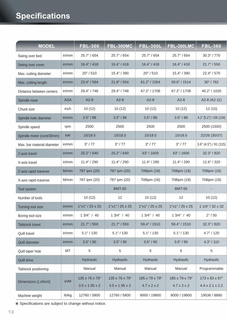
Specifications are subject to change without notice.
in/mm
in/mm
in/mm
in/mm
in/mm
ASA
inch
in/mm
rpm
kW
in/mm
in/mm
in/mm
M/min
M/min
in/mm
in/mm
in/mm
in/mm
in/mm
MT
in/M
Ib/kg
Swing over bed
Swing over cover
Max. cutting diameter
Max. cutting length
Distance between centers
Spindle nose
Chuck size
Spindle hole diameter
Spindle speed
Spindle motor (cont/30min)
Max. bar material diameter
Z-axis travel
X-axis travel
Z-axis rapid traverse
X-axis rapid traverse
Tool system
Number of tools
Turning tool size
Boring tool size
Tailstock travel
Quill travel
Quill diameter
Quill taper hole
Quill drive
Tailstock positioning
Dimensions (LxWxH)
Machine weight
30.3" / 770
21.7" / 550
22.4" / 570
30" / 762
40.2" / 1020
A2-8 (A2-11)
12 (15)
4.1" (5.2") / 105 (134)
2500 (1500)
22/26 (30/37)
3.6" (4.5") / 91 (115)
32.3" / 820
12.6" / 320
708ipm (18)
708ipm (18)
-
10 (12)
1 1/4" / 32 x 32
2" / 50
32.3" / 820
4.7" / 120
4.3" / 110
5
Hydraulic
Programmable
173 x 83 x 87"
4.4 x 2.1 x 2.2
19536 / 8880
FBL-360
25.7" / 654
16.4" / 418
15.4" / 390
21.8" / 554
29.4" / 748
A2-8
10 (12)
3.5" / 88
2500
15/18.5
3" / 77
25.2" / 640
11.4" / 290
787 ipm (20)
787 ipm (20)
BMT-65
12
1"x1" / 25 x 25
1 3/4" / 40
21.7" / 550
5.1" / 130
3.5" / 90
5
Hydraulic
Manual
135 x 76 x 79"
3.5 x 1.95 x 2
12760 / 5800
FBL-300MC
25.7" / 654
16.4" / 418
20" / 510
61.2" / 1554
67.2" / 1708
A2-8
10 (12)
3.5" / 88
2500
15/18.5
3" / 77
63" / 1600
11.4" / 290
708ipm (18)
708ipm (18)
-
10 (12)
1"x1" / 25 x 25
1 3/4" / 40
59.4" / 1510
5.1" / 130
3.5" / 90
5
Hydraulic
Manual
185 x 79 x 79"
4.7 x 2 x 2
9000 / 19800
FBL-300L
25.7" / 654
16.4" / 418
15.4" / 390
59.6" / 1514
67.2" / 1708
A2-8
10 (12)
3.5" / 88
2500
15/18.5
3" / 77
63" / 1600
11.4" / 290
708ipm (18)
708ipm (18)
BMT-65
12
1"x1" / 25 x 25
1 3/4" / 40
59.4" / 1510
5.1" / 130
3.5" / 90
5
Hydraulic
Manual
185 x 79 x 79"
4.7 x 2 x 2
9000 / 19800
FBL-300LMC
25.7" / 654
16.4" / 418
20" / 510
23.4" / 594
29.4" / 748
A2-8
10 (12)
3.5" / 88
2500
15/18.5
3" / 77
25.2" / 640
11.4" / 290
787 ipm (20)
787 ipm (20)
-
10 (12)
1"x1" / 25 x 25
1 3/4" / 40
21.7" / 550
5.1" / 130
3.5" / 90
5
Hydraulic
Manual
135 x 76 x 79"
3.5 x 1.95 x 2
12760 / 5800
FBL-300
Specifications
MODEL

14
30.3" / 770
21.7" / 550
17.8" / 452
29.1" / 739
40.2" / 1020
A2-8 (A2-11)
12 (15)
4.1" (5.2") / 105 (134)
2500 (1500)
18.5/22 (22/26)
3.6" (4.5") / 91 (115)
32.3" / 820
12.6" / 320
708ipm (18)
708ipm (18)
BMT-75
12
1 1/4" / 32 x 32
2" / 50
32.3" / 820
4.7" / 120
4.3" / 110
5
Hydraulic
Programmable
173 x 83 x 87"
4.4 x 2.1 x 2.2
19536 / 8880
FBL-360MC
30.3" / 770
21.7" / 550
22.4" / 570
79.8" / 2026
90.6" / 2300
A2-8 (A2-11)
12 (15)
4.1" (5.2") / 105 (134)
2500 (1500)
22/26 (30/37)
3.6" (4.5") / 91 (115)
82.7" / 2100
12.6" / 320
708ipm (18)
708ipm (18)
-
10 (12)
1 1/4" / 32 x 32
2" / 50
78.7" / 2000
4.7" / 120
4.3" / 110
5
Hydraulic
Programmable
228 x 89 x 91"
5.8 x 2.25 x 2.3
28072 / 12760
FBL-360L
30.3" / 770
21.7" / 550
17.8" / 452
78.6" / 1997
90.6" / 2300
A2-8 (A2-11)
12 (15)
4.1" (5.2") / 105 (134)
2500 (1500)
18.5/22 (22/26)
3.6" (4.5") / 91 (115)
82.7" / 2100
12.6" / 320
708ipm (18)
708ipm (18)
BMT-75
12
1 1/4" / 32 x 32
2" / 50
78.7" / 2000
4.7" / 120
4.3" / 110
5
Hydraulic
Programmable
228 x 89 x 91"
5.8 x 2.25 x 2.3
28072 / 12760
FBL-360LMC
33.1" / 840
26.1" / 662
25.6" / 650
27.3" / 694
32.3" / 820
A2-15
15
6" / 153
1400
22/26 (30/37)
5.5" / 140
32.3" / 820
14.2" / 360
708ipm (18)
708ipm (18)
-
10 (12)
1 1/4" / 32 x 32
2" / 50
32.3" / 820
4.7" / 120
4.3" / 110
5
Hydraulic
Programmable
169 x 89 x 87"
4.3 x 2.25 x 2.2
20900 / 9500
FBL-460
33.1" / 840
26.1" / 662
20.9" / 530
26.2" / 665
32.3" / 820
A2-15
15
6" / 153
1400
22/26 (30/37)
5.5" / 140
32.3" / 820
14.2" / 360
708ipm (18)
708ipm (18)
BMT-75
12
1 1/4" / 32 x 32
2" / 50
32.3" / 820
4.7" / 120
4.3" / 110
5
Hydraulic
Programmable
169 x 89 x 87"
4.3 x 2.25 x 2.2
20900 / 9500
FBL-460MC
33.1" / 840
26.1" / 662
25.6" / 650
78.4" / 1992
86.6" / 2200
A2-15
15
6" / 153
1400
22/26 (30/37)
5.5" / 140
78.7" / 2000
14.2" / 360
708ipm (18)
708ipm (18)
-
10 (12)
1 1/4" / 32 x 32
2" / 50
78.7" / 2000
4.7" / 120
4.3" / 110
5
Hydraulic
Programmable
228 x 89 x 91"
5.8 x 2.25 x 2.3
29700 / 13500
FBL-460L
33.1" / 840
26.1" / 662
20.9" / 530
77.2" / 1960
86.6" / 2200
A2-15
15
6" / 153
1400
22/26 (30/37)
5.5" / 140
78.7" / 2000
14.2" / 360
708ipm (18)
708ipm (18)
BMT-75
12
1 1/4" / 32 x 32
2" / 50
78.7" / 2000
4.7" / 120
4.3" / 110
5
Hydraulic
Programmable
228 x 89 x 91"
5.8 x 2.25 x 2.3
29700 / 13500
FBL-460LMC

Visual Design / tel +886 4 3703 8989 201406 Ver. 2
286 2920 324
762
3530
4005
1931
1950
2302
2250
5331485
110
763
5819
2150
2230
2145
630.3 964 68
2189.1109.8 4049.2 273.7
41594432.7
762
996 1081.5 1081.5 1000
2310
FBL-360 / 460 / MC
FBL-300L / MC
FBL-360L / 460L / MC
FBL-300 / MC
2072
1980
1000
5554491
4776286 799
763
Unit: mmDimensions