bowen li, changhong fu , fangqiang ding, junjie ye, and
TRANSCRIPT

ADTrack: Target-Aware Dual Filter Learning for Real-Time Anti-DarkUAV Tracking
Bowen Li, Changhong Fu∗, Fangqiang Ding, Junjie Ye, and Fuling Lin
Abstract— Prior correlation filter (CF)-based tracking meth-ods for unmanned aerial vehicles (UAVs) have virtually focusedon tracking in the daytime. However, when the night falls, thetrackers will encounter more harsh scenes, which can easilylead to tracking failure. In this regard, this work proposes anovel tracker with anti-dark function (ADTrack). The proposedmethod integrates an efficient and effective low-light imageenhancer into a CF-based tracker. Besides, a target-aware maskis simultaneously generated by virtue of image illuminationvariation. The target-aware mask can be applied to jointlytrain a target-focused filter that assists the context filter forrobust tracking. Specifically, ADTrack adopts dual regression,where the context filter and the target-focused filter restricteach other for dual filter learning. Exhaustive experiments areconducted on typical dark sceneries benchmark, consisting of37 typical night sequences from authoritative benchmarks, i.e.,UAVDark, and our newly constructed benchmark UAVDark70.The results have shown that ADTrack favorably outperformsother state-of-the-art trackers and achieves a real-time speedof 34 frames/s on a single CPU, greatly extending robust UAVtracking to night scenes.
I. INTRODUCTION
Widely applied in the field of robotics and automation,visual object tracking aims at predicting the location and sizeof a target object. Particularly, applying tracking methodsonboard unmanned aerial vehicles (UAVs) has facilitatedextensive UAV-based applications, e.g., collision avoidance[1], autonomous aerial manipulation operations [2], andautonomous transmission-line inspection [3].
Scenarios suitable to deploy visual trackers are currentlylimited to daytime when the light condition is favorableand the object is easily distinguished with representativegeometric and radiometric characteristics. As the night falls,the cameras fail to acquire sufficient information to completethe details of images, bringing great challenges to trackersand huge limitations to the generality and serviceability ofUAV.
Compared with generic tracking scenes, visual trackingfor UAV in the dark is confronted with more terribleconditions as follows: a) the object is apt to merge inthe dark environment, making its external contour unclear;b) objects’ color feature is usually invalid, ending up inits internal characteristics not significant; c) random noisesappear frequently on images captured at night, severelydistracting the tracker; d) limited computation and storageresources on UAV set barriers to real-time tracking. Due to
Bowen Li, Changhong Fu, Fangqiang Ding, Junjie Ye, and Fuling Linare with the School of Mechanical Engineering, Tongji University, 201804Shanghai, China. [email protected]∗Corresponding Author
Res
ponse
s ADTrack
Baseline
#69#16 #41 #65
Tra
ckin
g r
esult
s
UAV
Object enters
darkness
ADTrackBaseline
Frame number (#)
Baseline lost
object
Over
lap s
core
motorbike5
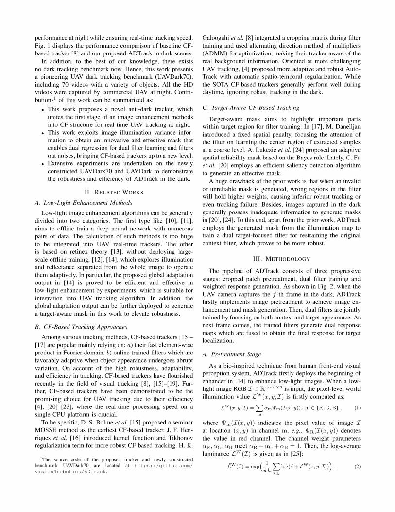
Fig. 1. Performance comparison of baseline tracker BACF [8] and proposedtracker ADTrack in dark sequence motorbike5. The shape of responsemap of BACF tracker is not ideal, which easily leads to tracking failurewhen the object merges into the dark. While the proposed ADTrack canmaintain satisfactory tracking even when the object is invisible in thedark. Green boxes denote the ground-truth. Some typical dark trackingscenes and performances of the SOTA trackers can be found at https://youtu.be/8ZnGOwoqDZ8.
the challenging tracking conditions above, current state-of-the-art (SOTA) methods [4]–[9] fail to up to scratch for UAVtracking in the dark.
Prior work gives few regards to robust tracking in thedark, which is essential and crucial to broaden the appli-cation range and service life of UAV. A direct strategy isto couple SOTA low-light enhancement methods [10]–[12]and trackers [4], [6], [8], i.e., operating tracking onto theenhanced images. Even if effective, such a simple fashionhas obvious drawbacks: a) most SOTA low-light enhancingmethods are time-consuming, thereby adds a heavy burdento the overall algorithm; b) merely employing preprocessingimages for tracking does not fully explore the potential ofenhancers; c) enhanced images usually have extra noises,interfering the tracker.
To this end, we propose a novel tracker with Anti-Dark function (ADTrack), conducting to render real-timeand robust tracking onboard UAV at night. To be specific,ADTrack embeds a high-speed low-light image enhancingalgorithm into an effective CF-based tracker framework.To our excitement, the image enhancing algorithm can beexplored to further generate a target-aware mask based onthe illumination information of an image. With the mask,ADTrack proposes a dual regression, where context filter andtarget-focused filter mutually restrict each other during train-ing, while in the detection stage, the dual filters complementeach other for more precise localization. Moreover, the maskfavorably filters out the noise brought by the enhancer. There-fore, the proposed ADTrack can maintain splendid tracking
arX
iv:2
106.
0249
5v1
[cs
.CV
] 4
Jun
202
1
performance at night while ensuring real-time tracking speed.Fig. 1 displays the performance comparison of baseline CF-based tracker [8] and our proposed ADTrack in dark scenes.
In addition, to the best of our knowledge, there existsno dark tracking benchmark now. Hence, this work presentsa pioneering UAV dark tracking benchmark (UAVDark70),including 70 videos with a variety of objects. All the HDvideos were captured by commercial UAV at night. Contri-butions1 of this work can be summarized as:• This work proposes a novel anti-dark tracker, which
unites the first stage of an image enhancement methodsinto CF structure for real-time UAV tracking at night.
• This work exploits image illumination variance infor-mation to obtain an innovative and effective mask thatenables dual regression for dual filter learning and filtersout noises, bringing CF-based trackers up to a new level.
• Extensive experiments are undertaken on the newlyconstructed UAVDark70 and UAVDark to demonstratethe robustness and efficiency of ADTrack in the dark.
II. RELATED WORKS
A. Low-Light Enhancement Methods
Low-light image enhancement algorithms can be generallydivided into two categories. The first type like [10], [11],aims to offline train a deep neural network with numerouspairs of data. The calculation of such methods is too hugeto be integrated into UAV real-time trackers. The otheris based on retinex theory [13], without deploying large-scale offline training, [12], [14], which explores illuminationand reflectance separated from the whole image to operatethem adaptively. In particular, the proposed global adaptationoutput in [14] is proved to be efficient and effective inlow-light enhancement by experiments, which is suitable forintegration into UAV tracking algorithm. In addition, theglobal adaptation output can be further deployed to generatea target-aware mask in this work to elevate robustness.
B. CF-Based Tracking Approaches
Among various tracking methods, CF-based trackers [15]–[17] are popular mainly relying on: a) their fast element-wiseproduct in Fourier domain, b) online trained filters which arefavorably adaptive when object appearance undergoes abruptvariation. On account of the high robustness, adaptability,and efficiency in tracking, CF-based trackers have flourishedrecently in the field of visual tracking [8], [15]–[19]. Fur-ther, CF-based trackers have been demonstrated to be thepromising choice for UAV tracking due to their efficiency[4], [20]–[23], where the real-time processing speed on asingle CPU platform is crucial.
To be specific, D. S. Bolme et al. [15] proposed a seminarMOSSE method as the earliest CF-based tracker. J. F. Hen-riques et al. [16] introduced kernel function and Tikhonovregularization term for more robust CF-based tracking. H. K.
1The source code of the proposed tracker and newly constructedbenchmark UAVDark70 are located at https://github.com/vision4robotics/ADTrack.
Galoogahi et al. [8] integrated a cropping matrix during filtertraining and used alternating direction method of multipliers(ADMM) for optimization, making their tracker aware of thereal background information. Oriented at more challengingUAV tracking, [4] proposed more adaptive and robust Auto-Track with automatic spatio-temporal regularization. Whilethe SOTA CF-based trackers generally perform well duringdaytime, ignoring robust tracking in the dark.
C. Target-Aware CF-Based Tracking
Target-aware mask aims to highlight important partswithin target region for filter training. In [17], M. Danelljanintroduced a fixed spatial penalty, focusing the attention ofthe filter on learning the center region of extracted samplesat a coarse level. A. Lukezic et al. [24] proposed an adaptivespatial reliability mask based on the Bayes rule. Lately, C. Fuet al. [20] employs an efficient saliency detection algorithmto generate an effective mask.
A huge drawback of the prior work is that when an invalidor unreliable mask is generated, wrong regions in the filterwill hold higher weights, causing inferior robust tracking oreven tracking failure. Besides, images captured in the darkgenerally possess inadequate information to generate masksin [20], [24]. To this end, apart from the prior work, ADTrackemploys the generated mask from the illumination map totrain a dual target-focused filter for restraining the originalcontext filter, which proves to be more robust.
III. METHODOLOGY
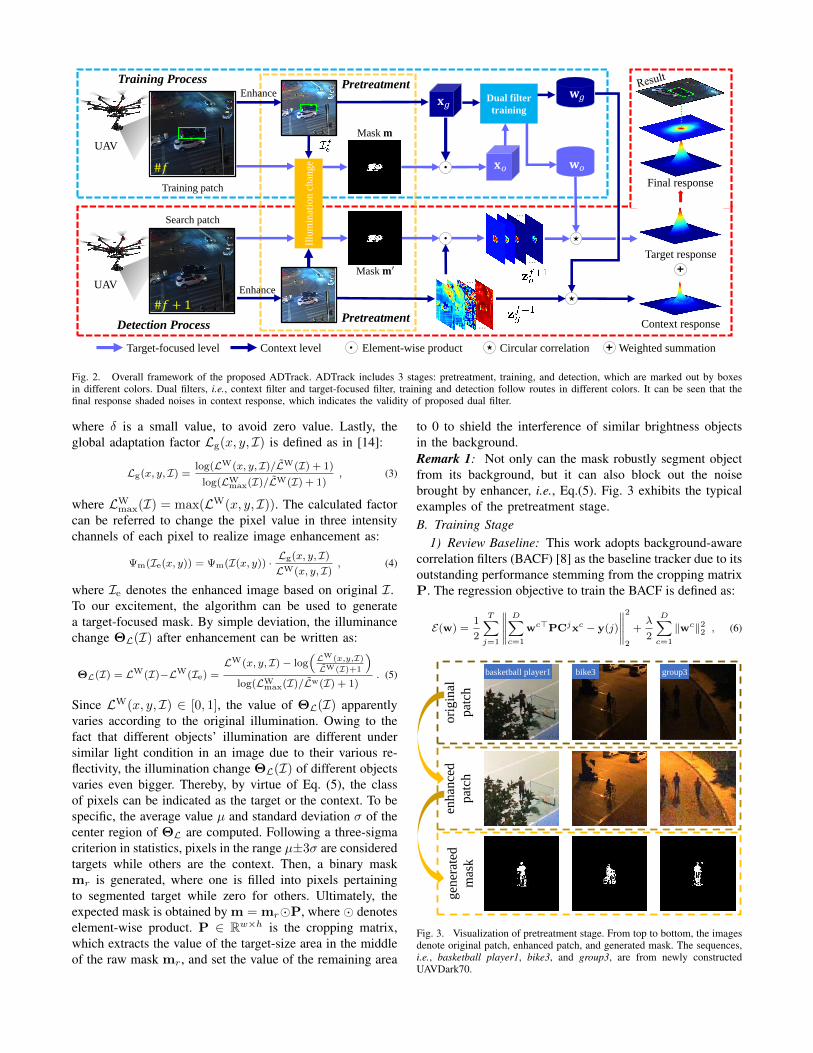
The pipeline of ADTrack consists of three progressivestages: cropped patch pretreatment, dual filter training andweighted response generation. As shown in Fig. 2, when theUAV camera captures the f -th frame in the dark, ADTrackfirstly implements image pretreatment to achieve image en-hancement and mask generation. Then, dual filters are jointlytrained by focusing on both context and target appearance. Asnext frame comes, the trained filters generate dual responsemaps which are fused to obtain the final response for targetlocalization.
A. Pretreatment Stage
As a bio-inspired technique from human front-end visualperception system, ADTrack firstly deploys the beginning ofenhancer in [14] to enhance low-light images. When a low-light image RGB I ∈ Rw×h×3 is input, the pixel-level worldillumination value LW(x, y, I) is firstly computed as:
LW(x, y, I) =∑m
αmΨm(I(x, y)), m ∈ {R,G,B} , (1)
where Ψm(I(x, y)) indicates the pixel value of image Iat location (x, y) in channel m, e.g., ΨR(I(x, y)) denotesthe value in red channel. The channel weight parametersαR, αG, αB meet αR +αG +αB = 1. Then, the log-averageluminance LW (I) is given as in [25]:
LW(I) = exp( 1
wh
∑x,y
log(δ + LW(x, y, I))), (2)
#𝑓
Mask 𝐦
Detection Process
Target response
Context response
Final response
Dual filter
training
Mask 𝐦′
Illu
min
atio
n c
han
ge
#𝑓 + 1
Enhance
Enhance
Training Process
…
…
Search patch
Training patch
𝐱𝑔
𝐱𝑜
𝐰𝑔
𝐰𝑜
…
…
Pretreatment
Pretreatment
Context levelTarget-focused level Element-wise product Circular correlation Weighted summation
UAV
UAV
Fig. 2. Overall framework of the proposed ADTrack. ADTrack includes 3 stages: pretreatment, training, and detection, which are marked out by boxesin different colors. Dual filters, i.e., context filter and target-focused filter, training and detection follow routes in different colors. It can be seen that thefinal response shaded noises in context response, which indicates the validity of proposed dual filter.
where δ is a small value, to avoid zero value. Lastly, theglobal adaptation factor Lg(x, y, I) is defined as in [14]:
Lg(x, y, I) =log(LW(x, y, I)/LW(I) + 1)
log(LWmax(I)/LW(I) + 1)
, (3)
where LWmax(I) = max(LW(x, y, I)). The calculated factor
can be referred to change the pixel value in three intensitychannels of each pixel to realize image enhancement as:
Ψm(Ie(x, y)) = Ψm(I(x, y)) ·Lg(x, y, I)
LW(x, y, I), (4)
where Ie denotes the enhanced image based on original I.To our excitement, the algorithm can be used to generatea target-focused mask. By simple deviation, the illuminancechange ΘL(I) after enhancement can be written as:
ΘL(I) = LW(I)−LW(Ie) =LW(x, y, I)− log
(LW(x,y,I)
LW(I)+1
)log(LW
max(I)/Lw(I) + 1). (5)
Since LW(x, y, I) ∈ [0, 1], the value of ΘL(I) apparentlyvaries according to the original illumination. Owing to thefact that different objects’ illumination are different undersimilar light condition in an image due to their various re-flectivity, the illumination change ΘL(I) of different objectsvaries even bigger. Thereby, by virtue of Eq. (5), the classof pixels can be indicated as the target or the context. To bespecific, the average value µ and standard deviation σ of thecenter region of ΘL are computed. Following a three-sigmacriterion in statistics, pixels in the range µ±3σ are consideredtargets while others are the context. Then, a binary maskmr is generated, where one is filled into pixels pertainingto segmented target while zero for others. Ultimately, theexpected mask is obtained by m = mr�P, where � denoteselement-wise product. P ∈ Rw×h is the cropping matrix,which extracts the value of the target-size area in the middleof the raw mask mr, and set the value of the remaining area
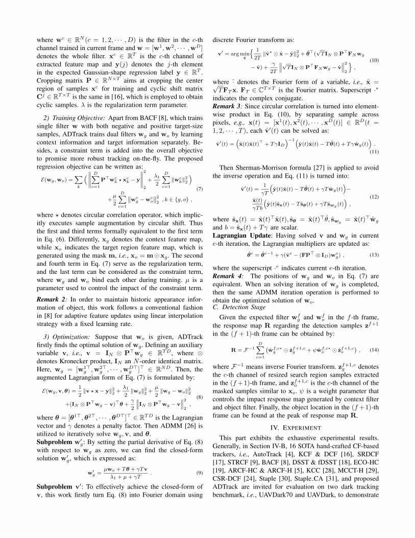
to 0 to shield the interference of similar brightness objectsin the background.Remark 1: Not only can the mask robustly segment objectfrom its background, but it can also block out the noisebrought by enhancer, i.e., Eq.(5). Fig. 3 exhibits the typicalexamples of the pretreatment stage.B. Training Stage
1) Review Baseline: This work adopts background-awarecorrelation filters (BACF) [8] as the baseline tracker due to itsoutstanding performance stemming from the cropping matrixP. The regression objective to train the BACF is defined as:
E(w) =1
2
T∑j=1
∥∥∥∥∥D∑
c=1
wc>PCjxc − y(j)
∥∥∥∥∥2
2
+λ
2
D∑c=1
‖wc‖22 , (6)
ori
gin
al
pat
ch
enh
ance
d
pat
chg
ener
ated
mas
k
bike3basketball player1 group3
Fig. 3. Visualization of pretreatment stage. From top to bottom, the imagesdenote original patch, enhanced patch, and generated mask. The sequences,i.e., basketball player1, bike3, and group3, are from newly constructedUAVDark70.
where wc ∈ RN (c = 1, 2, · · · , D) is the filter in the c-thchannel trained in current frame and w = [w1,w2, · · · ,wD]denotes the whole filter. xc ∈ RT is the c-th channel ofextracted feature map and y(j) denotes the j-th elementin the expected Gaussian-shape regression label y ∈ RT .Cropping matrix P ∈ RN×T aims at cropping the centerregion of samples xc for training and cyclic shift matrixCj ∈ RT×T is the same in [16], which is employed to obtaincyclic samples. λ is the regularization term parameter.
2) Training Objective: Apart from BACF [8], which trainssingle filter w with both negative and positive target-sizesamples, ADTrack trains dual filters wg and wo by learningcontext information and target information separately. Be-sides, a constraint term is added into the overall objectiveto promise more robust tracking on-the-fly. The proposedregression objective can be written as:
E(wg ,wo) =∑k
(∥∥∥∥∥D∑
c=1
P>wck ? xc
k − y
∥∥∥∥∥2
2
+λ1
2
D∑c=1
‖wck‖
22
)
+µ
2
D∑c=1
∥∥wcg −wc
o
∥∥2
2, k ∈ {g, o} ,
(7)
where ? denotes circular correlation operator, which implic-itly executes sample augmentation by circular shift. Thusthe first and third terms formally equivalent to the first termin Eq. (6). Differently, xg denotes the context feature map,while xo indicates the target region feature map, which isgenerated using the mask m, i.e., xo = m�xg . The secondand fourth term in Eq. (7) serve as the regularization term,and the last term can be considered as the constraint term,where wg and wo bind each other during training. µ is aparameter used to control the impact of the constraint term.
Remark 2: In order to maintain historic appearance infor-mation of object, this work follows a conventional fashionin [8] for adaptive feature updates using linear interpolationstrategy with a fixed learning rate.
3) Optimization: Suppose that wo is given, ADTrackfirstly finds the optimal solution of wg . Defining an auxiliaryvariable v, i.e., v = IN ⊗ P>wg ∈ RTD, where ⊗denotes Kronecker product, IN an N -order identical matrix.Here, wg = [w1>
g ,w2>g , · · · ,wD>
g ]> ∈ RND. Then, theaugmented Lagrangian form of Eq. (7) is formulated by:
E(wg ,v,θ) =1
2‖v ? x− y‖22 +
λ1
2‖wg‖22 +
µ
2‖wg −wo‖22
+(IN ⊗P>wg − v)>θ +γ
2
∥∥∥IN ⊗P>wg − v∥∥∥2
2,
(8)
where θ = [θ1>,θ2>, · · · ,θD>]> ∈ RTD is the Lagrangianvector and γ denotes a penalty factor. Then ADMM [26] isutilized to iteratively solve wg,v, and θ.Subproblem w′g: By setting the partial derivative of Eq. (8)with respect to wg as zero, we can find the closed-formsolution w′g , which is expressed as:
w′g =µwo + Tθ + γTv
λ1 + µ+ γT. (9)
Subproblem v′: To effectively achieve the closed-form ofv, this work firstly turn Eq. (8) into Fourier domain using
discrete Fourier transform as:
v′ = arg minv
{ 1
2T‖v∗ � x− y‖22 + θ>(
√T IN ⊗P>FNwg
− v) +γ
2T
∥∥∥√T IN ⊗P>FNwg − v∥∥∥2
2
},
(10)
where · denotes the Fourier form of a variable, i.e., x =√TFTx. FT ∈ CT×T is the Fourier matrix. Superscript ·∗
indicates the complex conjugate.Remark 3: Since circular correlation is turned into element-wise product in Eq. (10), by separating sample acrosspixels, e.g., x(t) = [x1(t),x2(t), · · · ,xD(t)] ∈ RD(t =1, 2, · · · , T ), each v′(t) can be solved as:
v′(t) =(x(t)x(t)> + TγID
)−1(y(t)x(t)− T θ(t) + Tγwg(t)
).
(11)
Then Sherman-Morrison formula [27] is applied to avoidthe inverse operation and Eq. (11) is turned into:
v′(t) =1
γT
(y(t)x(t)− T θ(t) + γT wg(t)
)−
x(t)
γTb
(y(t)sx(t)− T sθ(t) + γT swg (t)
),
(12)
where sx(t) = x(t)>x(t), sθ = x(t)>θ, swg= x(t)>wg
and b = sx(t) + Tγ are scalar.Lagrangian Update: Having solved v and wg in currente-th iteration, the Lagrangian multipliers are updated as:
θe = θe−1 + γ(ve − (FP> ⊗ ID)weg) , (13)
where the superscript ·e indicates current e-th iteration.Remark 4: The positions of wg and wo in Eq. (7) areequivalent. When an solving iteration of wg is completed,then the same ADMM iteration operation is performed toobtain the optimized solution of wo.C. Detection Stage
Given the expected filter wfg and wf
o in the f -th frame,the response map R regarding the detection samples zf+1
in the (f + 1)-th frame can be obtained by:
R = F−1D∑
c=1
(wf,c∗
g � zf+1,cg + ψwf,c∗
o � zf+1,co
), (14)
where F−1 means inverse Fourier transform. zf+1,cg denotes
the c-th channel of resized search region samples extractedin the (f +1)-th frame, and zf+1,c
o is the c-th channel of themasked samples similar to xo. ψ is a weight parameter thatcontrols the impact response map generated by context filterand object filter. Finally, the object location in the (f +1)-thframe can be found at the peak of response map R.
IV. EXPERIMENT
This part exhibits the exhaustive experimental results.Generally, in Section IV-B, 16 SOTA hand-crafted CF-basedtrackers, i.e., AutoTrack [4], KCF & DCF [16], SRDCF[17], STRCF [9], BACF [8], DSST & fDSST [18], ECO-HC[19], ARCF-HC & ARCF-H [5], KCC [28], MCCT-H [29],CSR-DCF [24], Staple [30], Staple CA [31], and proposedADTrack are invited for evaluation on two dark trackingbenchmark, i.e., UAVDark70 and UAVDark, to demonstrate

0 10 20 30 40 50Location error threshold
0
0.2
0.4
0.6
0.8P
reci
sion
Precision plots on UAVDark70
ADTrack [0.712]AutoTrack [0.681]ARCF-H [0.643]BACF [0.630]ECO-HC [0.575]Staple [0.535]Staple_CA [0.480]MCCT-H [0.452]KCC [0.438]fDSST [0.429]DSST [0.401]DCF [0.364]KCF [0.363]
0 0.5 1Overlap threshold
0
0.2
0.4
0.6
0.8
Succ
ess
rate
Success plots on UAVDark70
ADTrack [0.502]AutoTrack [0.483]ARCF-H [0.467]BACF [0.451]ECO-HC [0.433]Staple [0.378]Staple_CA [0.354]fDSST [0.341]MCCT-H [0.328]KCC [0.316]DSST [0.304]DCF [0.264]KCF [0.261]
(a) Results on UAVDark70
0 10 20 30 40 50Location error threshold
0
0.2
0.4
0.6
0.8
Pre
cisi
on
Precision plots on UAVDark
ADTrack [0.786]Staple [0.777]AutoTrack [0.775]ARCF-H [0.767]Staple_CA [0.764]ECO-HC [0.756]BACF [0.752]MCCT-H [0.747]DSST [0.742]KCC [0.740]fDSST [0.731]KCF [0.712]DCF [0.704]
0 0.5 1Overlap threshold
0
0.2
0.4
0.6
0.8Su
cces
s ra
teSuccess plots on UAVDark
ADTrack [0.505]AutoTrack [0.501]BACF [0.498]Staple [0.484]ECO-HC [0.480]MCCT-H [0.470]Staple_CA [0.469]ARCF-H [0.469]KCC [0.469]DSST [0.451]fDSST [0.444]KCF [0.394]DCF [0.391]
(b) Results on UAVDark
Fig. 4. Overall performance of real-time hand-crafted DCF-based trackerson the benchmark UAVDark70 and UAVDark. The evaluation metric inprecision plot is DP, and the metric in success rate plot is AUC. ClearlyADTrack maintains its robustness in 2 benchmarks by virtue of its dualregression.
the superiority of the proposed ADTrack comprehensively.Specially, in Section IV-E as displayed in TABLE IV andTABLE V, deep trackers deploying convolutional neuralnetwork (CNN), have also been evaluated.
A. Implementation Information1) Platform: The experiments extended in this work were
all performed on MATLAB R2019a. The main hardwareadopted consists of an Intel Core I7-8700K CPU, 32GBRAM, and an NVIDIA RTX 2080 GPU.
2) Parameters: To guarantee the fairness and objectivityof the evaluation, the tested trackers from other works havemaintained their official initial parameters.
The parameters of the regression equation in ADTrack areas follows, λ1 = λ2 = 0.01 and µ is set as 200. For the hyperparameters of ADMM, ADTrack sets γmax = 10000, γ0 = 1,and the numbers of iteration for wg and wo are both 3.During detection, weight ψ is set as 0.02. Note that bothcontext and target appearance adopts a learning rate η1 =0.02 to implement feature update.
3) Features and Scale Estimation: ADTrack uses hand-crafted features for appearance representations, i.e., gray-scale, a fast version of histogram of oriented gradient (fHOG)[32], and color names (CN) [33]. Note that gray-scale andCN features can be valid in ADTrack thanks to low-lightenhancement. The cell size for feature extraction is set as4 × 4. ADTrack adopts the scale filter proposed by [18] toperform accurate scale estimation.B. Overall Evaluation
Figure 4 shows the overall success rate and precisioncomparison of the real-time trackers.
Benchmark UAVDark70 is newly made in this work,consisting of 70 manually annotated sequences. All the
#00001
#00138
#00673
girl4 running2
#00009
#00189
#00346
#00003
#00402
#00411
#00039
#00501
#00752
group3 signpost6
Ground-truth
Fig. 5. Visualization of some typical tracking scenes. Sequences, i.e., girl4,group3, running2, and signpost6, which indicate the targets, are from thenewly constructed UAVDark70. Clearly, when other trackers lost the objectin the dark, ADTrack ensured its robustness in darkness mainly due to itstarget-aware mask and dual regression.
scenes were shot from a professional grade UAV at night. InFig. 4(a), ADTrack outperforms all other arts and improvesthe baseline BACF [8] tracker by 10.2% under distanceprecision (DP) at center location error (CLE) = 20 pixels. Interms of area under curve (AUC), ADTrack ranks the first aswell. Fig. 5 displays some typical dark tracking scenes andperformance of the SOTA trackers in UAVDark70.
In order to maintain the objectivity, this work selectedtypical night scenes from the authoritative publicly availablebenchmark UAVDT [34] and Visdrone-2019SOT [35] (to-tally 37 sequences), and composed them into a new bench-mark, i.e., UAVDark. In Fig. 4(b), ADTrack outperforms allothers in both DP and AUC. Specifically, ADTrack improvesthe DP of baseline BACF by more than 4.5% in UAVDark.
TABLE I shows the top 11 hand-crafted CF-based track-ers’ (both real-time and not real-time) venues and averageresults on 2 benchmarks, where ADTrack outperforms allother hand-crafted trackers. Besides, ADTrack achieves aspeed of 34 FPS, meeting real-time requirement on UAVtracking.Remark 5: The sequences in the newly made UAVDark70are more common in real-world dark tracking, where thescenes are generally much darker, bringing more challengesto trackers.C. Analysis by Attributes
Following [21], this work considers the UAV specialtracking challenges as low resolution (LR), fast motion (FM),illumination variation (IV), viewpoint change (VC), andocclusion (OCC). In terms of UAVDark70, the attributes aremanually annotated according to the same criterion in [35].TABLE II exhibits the average by sequences results of the top8 real-time CF-based trackers in UAVDark and UAVDark70according to TABLE I, where ADTrack ranks the first inmost attributes.
D. Ablation Studies
This part exhibits the validity of different componentsin ADTrack on tracking. BACF e denotes adding only theenhancing factor on the baseline tracker BACF [8]. AD-Track e means ADTrack without dual filters (considered theBaseline). ADTrack ew indicates adding merely weighted
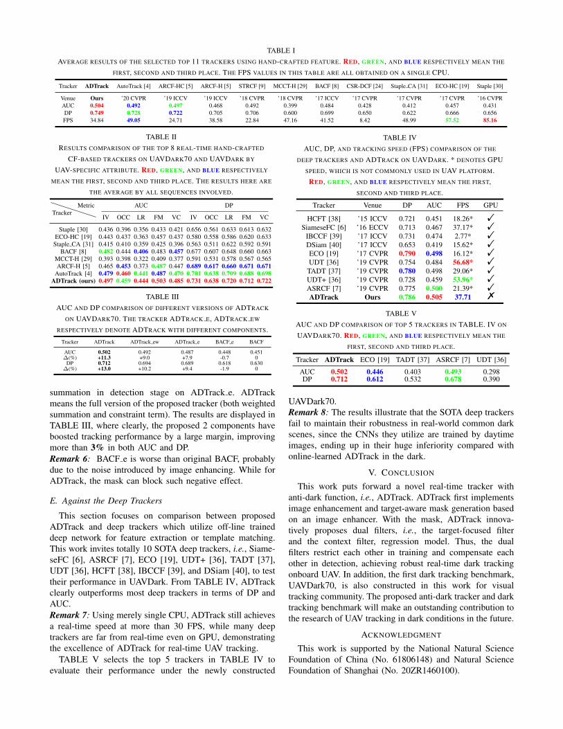
TABLE IAVERAGE RESULTS OF THE SELECTED TOP 11 TRACKERS USING HAND-CRAFTED FEATURE. RED, GREEN, AND BLUE RESPECTIVELY MEAN THE
FIRST, SECOND AND THIRD PLACE. THE FPS VALUES IN THIS TABLE ARE ALL OBTAINED ON A SINGLE CPU.
Tracker ADTrack AutoTrack [4] ARCF-HC [5] ARCF-H [5] STRCF [9] MCCT-H [29] BACF [8] CSR-DCF [24] Staple CA [31] ECO-HC [19] Staple [30]
Venue Ours ’20 CVPR ’19 ICCV ’19 ICCV ’18 CVPR ’18 CVPR ’17 ICCV ’17 CVPR ’17 CVPR ’17 CVPR ’16 CVPRAUC 0.504 0.492 0.497 0.468 0.492 0.399 0.484 0.428 0.412 0.457 0.431DP 0.749 0.728 0.722 0.705 0.706 0.600 0.699 0.650 0.622 0.666 0.656FPS 34.84 49.05 24.71 38.58 22.84 47.16 41.52 8.42 48.99 57.52 85.16
TABLE IIRESULTS COMPARISON OF THE TOP 8 REAL-TIME HAND-CRAFTED
CF-BASED TRACKERS ON UAVDARK70 AND UAVDARK BY
UAV-SPECIFIC ATTRIBUTE. RED, GREEN, AND BLUE RESPECTIVELY
MEAN THE FIRST, SECOND AND THIRD PLACE. THE RESULTS HERE ARE
THE AVERAGE BY ALL SEQUENCES INVOLVED.
TrackerMetric AUC DP
IV OCC LR FM VC IV OCC LR FM VC
Staple [30] 0.436 0.396 0.356 0.433 0.421 0.656 0.561 0.633 0.613 0.632ECO-HC [19] 0.443 0.437 0.363 0.457 0.437 0.580 0.558 0.586 0.620 0.633
Staple CA [31] 0.415 0.410 0.359 0.425 0.396 0.563 0.511 0.622 0.592 0.591BACF [8] 0.482 0.444 0.406 0.483 0.457 0.677 0.607 0.648 0.660 0.663
MCCT-H [29] 0.393 0.398 0.322 0.409 0.377 0.591 0.531 0.578 0.567 0.565ARCF-H [5] 0.465 0.453 0.373 0.487 0.447 0.689 0.617 0.660 0.671 0.671
AutoTrack [4] 0.479 0.460 0.441 0.487 0.470 0.701 0.638 0.709 0.688 0.698ADTrack (ours) 0.497 0.459 0.444 0.503 0.485 0.731 0.638 0.720 0.712 0.722
TABLE IIIAUC AND DP COMPARISON OF DIFFERENT VERSIONS OF ADTRACK
ON UAVDARK70. THE TRACKER ADTRACK E, ADTRACK EW
RESPECTIVELY DENOTE ADTRACK WITH DIFFERENT COMPONENTS.
Tracker ADTrack ADTrack ew ADTrack e BACF e BACF
AUC 0.502 0.492 0.487 0.448 0.451∆(%) +11.3 +9.0 +7.9 -0.7 0
DP 0.712 0.694 0.689 0.618 0.630∆(%) +13.0 +10.2 +9.4 -1.9 0
summation in detection stage on ADTrack e. ADTrackmeans the full version of the proposed tracker (both weightedsummation and constraint term). The results are displayed inTABLE III, where clearly, the proposed 2 components haveboosted tracking performance by a large margin, improvingmore than 3% in both AUC and DP.Remark 6: BACF e is worse than original BACF, probablydue to the noise introduced by image enhancing. While forADTrack, the mask can block such negative effect.
E. Against the Deep Trackers
This section focuses on comparison between proposedADTrack and deep trackers which utilize off-line traineddeep network for feature extraction or template matching.This work invites totally 10 SOTA deep trackers, i.e., Siame-seFC [6], ASRCF [7], ECO [19], UDT+ [36], TADT [37],UDT [36], HCFT [38], IBCCF [39], and DSiam [40], to testtheir performance in UAVDark. From TABLE IV, ADTrackclearly outperforms most deep trackers in terms of DP andAUC.Remark 7: Using merely single CPU, ADTrack still achievesa real-time speed at more than 30 FPS, while many deeptrackers are far from real-time even on GPU, demonstratingthe excellence of ADTrack for real-time UAV tracking.
TABLE V selects the top 5 trackers in TABLE IV toevaluate their performance under the newly constructed
TABLE IVAUC, DP, AND TRACKING SPEED (FPS) COMPARISON OF THE
DEEP TRACKERS AND ADTRACK ON UAVDARK. * DENOTES GPUSPEED, WHICH IS NOT COMMONLY USED IN UAV PLATFORM.RED, GREEN, AND BLUE RESPECTIVELY MEAN THE FIRST,
SECOND AND THIRD PLACE.
Tracker Venue DP AUC FPS GPU
HCFT [38] ’15 ICCV 0.721 0.451 18.26* !SiameseFC [6] ’16 ECCV 0.713 0.467 37.17* !
IBCCF [39] ’17 ICCV 0.731 0.474 2.77* !DSiam [40] ’17 ICCV 0.653 0.419 15.62* !ECO [19] ’17 CVPR 0.790 0.498 16.12* !UDT [36] ’19 CVPR 0.754 0.484 56.68* !
TADT [37] ’19 CVPR 0.780 0.498 29.06* !UDT+ [36] ’19 CVPR 0.728 0.459 53.96* !ASRCF [7] ’19 CVPR 0.775 0.500 21.39* !ADTrack Ours 0.786 0.505 37.71 %
TABLE VAUC AND DP COMPARISON OF TOP 5 TRACKERS IN TABLE. IV ON
UAVDARK70. RED, GREEN, AND BLUE RESPECTIVELY MEAN THE
FIRST, SECOND AND THIRD PLACE.
Tracker ADTrack ECO [19] TADT [37] ASRCF [7] UDT [36]
AUC 0.502 0.446 0.403 0.493 0.298DP 0.712 0.612 0.532 0.678 0.390
UAVDark70.Remark 8: The results illustrate that the SOTA deep trackersfail to maintain their robustness in real-world common darkscenes, since the CNNs they utilize are trained by daytimeimages, ending up in their huge inferiority compared withonline-learned ADTrack in the dark.
V. CONCLUSION
This work puts forward a novel real-time tracker withanti-dark function, i.e., ADTrack. ADTrack first implementsimage enhancement and target-aware mask generation basedon an image enhancer. With the mask, ADTrack innova-tively proposes dual filters, i.e., the target-focused filterand the context filter, regression model. Thus, the dualfilters restrict each other in training and compensate eachother in detection, achieving robust real-time dark trackingonboard UAV. In addition, the first dark tracking benchmark,UAVDark70, is also constructed in this work for visualtracking community. The proposed anti-dark tracker and darktracking benchmark will make an outstanding contribution tothe research of UAV tracking in dark conditions in the future.
ACKNOWLEDGMENT
This work is supported by the National Natural ScienceFoundation of China (No. 61806148) and Natural ScienceFoundation of Shanghai (No. 20ZR1460100).

REFERENCES
[1] T. Baca, D. Hert, G. Loianno, M. Saska, and V. Kumar, “ModelPredictive Trajectory Tracking and Collision Avoidance for Reli-able Outdoor Deployment of Unmanned Aerial Vehicles,” in 2018IEEE/RSJ International Conference on Intelligent Robots and Systems(IROS), 2018, pp. 6753–6760.
[2] D. R. McArthur, Z. An, and D. J. Cappelleri, “Pose-Estimate-BasedTarget Tracking for Human-Guided Remote Sensor Mounting with aUAV,” in Proceedings of IEEE International Conference on Roboticsand Automation (ICRA), 2020, pp. 10 636–10 642.
[3] J. Bian, X. Hui, X. Zhao, and M. Tan, “A Novel Monocular-Based Navigation Approach for UAV Autonomous Transmission-LineInspection,” in Proceedings of IEEE/RSJ International Conference onIntelligent Robots and Systems (IROS), 2018, pp. 1–7.
[4] Y. Li, C. Fu, F. Ding, Z. Huang, and G. Lu, “AutoTrack: TowardsHigh-Performance Visual Tracking for UAV with Automatic Spatio-Temporal Regularization,” in Proceedings of IEEE Conference onComputer Vision and Pattern Recognition (CVPR), 2020, pp. 11 923–11 932.
[5] Z. Huang, C. Fu, Y. Li, F. Lin, and P. Lu, “Learning AberranceRepressed Correlation Filters for Real-Time UAV Tracking,” in Pro-ceedings of the IEEE International Conference on Computer Vision(ICCV), 2019, pp. 2891–2900.
[6] L. Bertinetto, J. Valmadre, J. F. Henriques, A. Vedaldi, and P. H. S.Torr, “Fully-Convolutional Siamese Networks for Object Tracking,”in Proceedings of European Conference on Computer Vision (ECCV),2016, pp. 850–865.
[7] K. Dai, D. Wang, H. Lu, C. Sun, and J. Li, “Visual Tracking viaAdaptive Spatially-Regularized Correlation Filters,” in Proceedingsof IEEE Conference on Computer Vision and Pattern Recognition(CVPR), 2019, pp. 4665–4674.
[8] H. K. Galoogahi, A. Fagg, and S. Lucey, “Learning Background-Aware Correlation Filters for Visual Tracking,” in Proceedings of IEEEInternational Conference on Computer Vision (ICCV), 2017, pp. 1144–1152.
[9] F. Li, C. Tian, W. Zuo, L. Zhang, and M. Yang, “Learning Spatial-Temporal Regularized Correlation Filters for Visual Tracking,” inProceedings of IEEE Conference on Computer Vision and PatternRecognition (CVPR), 2018, pp. 4904–4913.
[10] Y. Zhang, J. Zhang, and X. Guo, “Kindling the Darkness: A PracticalLow-Light Image Enhancer,” in Proceedings of the ACM InternationalConference on Multimedia (ACM), 2019, pp. 1632–1640.
[11] S. Park, S. Yu, M. Kim, K. Park, and J. Paik, “Dual AutoencoderNetwork for Retinex-Based Low-Light Image Enhancement,” IEEEAccess, vol. 6, pp. 22 084–22 093, 2018.
[12] M. Li, J. Liu, W. Yang, X. Sun, and Z. Guo, “Structure-RevealingLow-Light Image Enhancement Via Robust Retinex Model,” IEEETransactions on Image Processing, vol. 27, no. 6, pp. 2828–2841,2018.
[13] E. H. Land, “The Retinex Theory of Color Vision,” Scientific Ameri-can, vol. 237, no. 6, pp. 108–129, 1977.
[14] H. Ahn, B. Keum, D. Kim, and H. S. Lee, “Adaptive Local ToneMapping Based on Retinex for High Dynamic Range Images,” in Pro-ceedings of IEEE International Conference on Consumer Electronics(ICCE), 2013, pp. 153–156.
[15] D. S. Bolme, J. R. Beveridge, B. A. Draper, and Y. M. Lui, “VisualObject Tracking Using Adaptive Correlation Filters,” in Proceedingsof IEEE Conference on Computer Vision and Pattern Recognition(CVPR), 2010, pp. 2544–2550.
[16] J. F. Henriques, R. Caseiro, P. Martins, and J. Batista, “High-SpeedTracking with Kernelized Correlation Filters,” IEEE Transactions onPattern Analysis and Machine Intelligence, vol. 37, no. 3, pp. 583–596,2015.
[17] M. Danelljan, G. Hager, F. S. Khan, and M. Felsberg, “LearningSpatially Regularized Correlation Filters for Visual Tracking,” inProceedings of IEEE International Conference on Computer Vision(ICCV), 2015, pp. 4310–4318.
[18] M. Danelljan, G. Hager, F. S. Khan, and M. Felsberg, “DiscriminativeScale Space Tracking,” IEEE Transactions on Pattern Analysis andMachine Intelligence, vol. 39, no. 8, pp. 1561–1575, 2017.
[19] M. Danelljan, G. Bhat, F. Shahbaz Khan, and M. Felsberg, “ECO:Efficient Convolution Operators for Tracking,” in Proceedings of IEEEConference on Computer Vision and Pattern Recognition (CVPR),2017, pp. 6638–6646.
[20] C. Fu, J. Xu, F. Lin, F. Guo, T. Liu, and Z. Zhang, “Object Saliency-Aware Dual Regularized Correlation Filter for Real-Time AerialTracking,” IEEE Transactions on Geoscience and Remote Sensing,pp. 1–12, 2020.
[21] C. Fu, B. Li, F. Ding, F. Lin, and G. Lu, “Correlation Filter for UAV-Based Aerial Tracking: A Review and Experimental Evaluation,” arXivpreprint arXiv:2010.06255, pp. 1–28, 2020.
[22] C. Fu, J. Ye et al., “Disruptor-Aware Interval-Based Response Incon-sistency for Correlation Filters in Real-Time Aerial Tracking,” IEEETransactions on Geoscience and Remote Sensing, pp. 1–13, 2020.
[23] F. Ding, C. Fu, Y. Li, J. Jin, and C. Feng, “Automatic Failure Recoveryand Re-Initialization for Online UAV Tracking with Joint Scale andAspect Ratio Optimization,” in Proceedings of IEEE/RSJ InternationalConference on Intelligent Robots and Systems (IROS), 2020, pp. 1–8.
[24] A. Lukezic, T. Vojir, L. Cehovin Zajc, J. Matas, and M. Kristan, “Dis-criminative Correlation Filter with Channel and Spatial Reliability,”in Proceedings of IEEE Conference on Computer Vision and PatternRecognition (CVPR), 2017, pp. 6309–6318.
[25] E. Reinhard, M. Stark, P. Shirley, and J. Ferwerda, “PhotographicTone Reproduction for Digital Images,” in Proceedings of the annualconference on Computer graphics and interactive techniques (ACM),2002, pp. 267–276.
[26] S. Boyd, N. Parikh, E. Chu, B. Peleato, and J. Eckstein, “DistributedOptimization and Statistical Learning via the Alternating DirectionMethod of Multipliers,” Foundations and Trends in Machine Learning,vol. 3, pp. 1–122, 2010.
[27] J. Sherman and W. J. Morrison, “Adjustment of An Inverse MatrixCorresponding to A Change in One Element of A Given Matrix,” TheAnnals of Mathematical Statistics, vol. 21, no. 1, pp. 124–127, 1950.
[28] C. Wang, L. Zhang, L. Xie, and J. Yuan, “Kernel Cross-Correlator,”in Proceedings of AAAI Conference on Artificial Intelligence (AAAI),2018, pp. 1–8.
[29] N. Wang, W. Zhou, Q. Tian, R. Hong, M. Wang, and H. Li, “Multi-cue Correlation Filters for Robust Visual Tracking,” in Proceedingsof IEEE Conference on Computer Vision and Pattern Recognition(CVPR), 2018, pp. 4844–4853.
[30] L. Bertinetto, J. Valmadre, S. Golodetz, O. Miksik, and P. H.Torr, “Staple: Complementary Learners for Real-time Tracking,” inProceedings of IEEE Conference on Computer Vision and PatternRecognition (CVPR), 2016, pp. 1401–1409.
[31] M. Mueller, N. Smith, and B. Ghanem, “Context-Aware CorrelationFilter Tracking,” in Proceedings of IEEE Conference on ComputerVision and Pattern Recognition (CVPR), 2017, pp. 1396–1404.
[32] P. F. Felzenszwalb, R. B. Girshick, D. McAllester, and D. Ramanan,“Object Detection with Discriminatively Trained Part-Based Models,”IEEE Transactions on Pattern Analysis and Machine Intelligence,vol. 32, no. 9, pp. 1627–1645, 2010.
[33] J. van de Weijer and C. Schmid, “Coloring Local Feature Extraction,”in Proceedings of European Conference on Computer Vision (ECCV),2006, pp. 334–348.
[34] D. Du, Y. Qi, H. Yu, Y. Yang, K. Duan, G. Li, W. Zhang, Q. Huang,and Q. Tian, “The Unmanned Aerial Vehicle Benchmark: ObjectDetection and Tracking,” in Proceedings of the European Conferenceon Computer Vision (ECCV), 2018, pp. 370–386.
[35] D. Du, P. Zhu et al., “VisDrone-SOT2019: The Vision Meets DroneSingle Object Tracking Challenge Results,” in Proceedings of Inter-national Conference on Computer Vision Workshops (ICCVW), 2019,pp. 1–14.
[36] N. Wang, Y. Song, C. Ma, W. Zhou, W. Liu, and H. Li, “UnsupervisedDeep Tracking,” in Proceedings of IEEE Conference on ComputerVision and Pattern Recognition (CVPR), 2019, pp. 1308–1317.
[37] X. Li, C. Ma, B. Wu, Z. He, and M.-H. Yang, “Target-Aware DeepTracking,” in Proceedings of IEEE Conference on Computer Visionand Pattern Recognition (CVPR), 2019, pp. 1369–1378.
[38] C. Ma, J. Huang, X. Yang, and M. Yang, “Hierarchical ConvolutionalFeatures for Visual Tracking,” in Proceedings of IEEE InternationalConference on Computer Vision (ICCV), 2015, pp. 3074–3082.
[39] F. Li, Y. Yao, P. Li, D. Zhang, W. Zuo, and M.-H. Yang, “IntegratingBoundary and Center Correlation Filters for Visual Tracking withAspect Ratio Variation,” in Proceedings of IEEE International Confer-ence on Computer Vision Workshops (ICCVW), 2017, pp. 2001–2009.
[40] Q. Guo, W. Feng, C. Zhou, R. Huang, L. Wan, and S. Wang,“Learning Dynamic Siamese Network for Visual Object Tracking,”in Proceedings of IEEE International Conference on Computer Vision(ICCV), 2017, pp. 1781–1789.