boudinage classification: end-member boudin types and
TRANSCRIPT

Boudinage classification: end-member boudin types
and modified boudin structuresq
Ben D. Goscombea,*, Cees W. Passchierb, Martin Handa
aContinental Evolution Research Group, Department of Geology and Geophysics, Adelaide University, Adelaide, S.A. 5005, AustraliabInstitut fuer Geowissenschaften, Johannes Gutenberg Universitaet, Becherweg 21, Mainz, Germany
Received 28 March 2002; received in revised form 25 August 2003; accepted 30 August 2003
Abstract
In monoclinic shear zones, there are only three ways a layer can be boudinaged, leading to three kinematic classes of boudinage. These are
(1) symmetrically without slip on the inter-boudin surface (no-slip boudinage), and two classes with asymmetrical slip on the inter-boudin
surface: slip being either (2) synthetic (S-slip boudinage) or (3) antithetic (A-slip boudinage) with respect to bulk shear sense. In S-slip
boudinage, the boudins rotate antithetically, and in antithetic slip boudinage they rotate synthetically with respect to shear sense. We have
investigated the geometry of 2100 natural boudins from a wide variety of geological contexts worldwide. Five end-member boudin block
geometries that are easily distinguished in the field encompass the entire range of natural boudins. These five end-member boudin block
geometries are characterized and named drawn, torn, domino, gash and shearband boudins. Groups of these are shown to operate almost
exclusively by only one kinematic class; drawn and torn boudins extend by no-slip, domino and gash boudins form by A-slip and shearband
boudins develop by S-slip boudinage. In addition to boudin block geometry, full classification must also consider boudin train obliquity with
respect to the fabric attractor and material layeredness of the boudinaged rock mass. Modified or complex boudin structures fall into two
categories: sequential boudins experienced a sequence of different boudin block geometry components during progressive boudinage (i.e.
continued stretch), whereas reworked boudins were modified by subsequent deformational episodes (folded, sheared and shortened types).
Correct classification of boudins and recognition of their modification are the crucial first stages of interpretation of natural boudin structures,
necessary to employing them as indicators of shear sense, flow regime and/or extension axes in terranes otherwise devoid of stretching
lineations.
q 2003 Elsevier Ltd. All rights reserved.
Keywords: Boudin; Boudinage; Shear zones; Modified boudin; Kinematic indicator
1. Introduction
Boudinage is the disruption of layers, bodies or foliation
planes within a rock mass in response to bulk extension
along the enveloping surface. Boudin structures were first
described by Ramsay (1881) and named by Lohest (1909).
The huge variety that occur in nature have been the subject
of considerable study (Wilson, 1961; Ramsay, 1967;
Etchecopar, 1974, 1977; Hobbs et al., 1976; Lloyd and
Ferguson, 1981; Lloyd et al., 1982; Blumenfeld, 1983;
Simpson and Schmid, 1983; Hanmer, 1984, 1986; Van der
Molen, 1985; Ramsay and Huber, 1987; Goldstein, 1988;
Lacassin, 1988; DePaor et al., 1991; Hanmer and Passchier,
1991; Swanson, 1992, 1999). Nevertheless, there has been
no attempt to erect a classification scheme for the full range
of natural boudin structures. We propose a simple
classification scheme that accounts for all simple unmodi-
fied boudin geometries that have been described and further,
relate these end-member boudin geometries in a hierarchical
scheme that considers their relationship to the three
kinematic classes by which boudinage occurs (Table 1;
Goscombe and Passchier, 2003). These kinematic classes
are: (1) symmetrical boudins, which do not experience slip
on the inter-boudin surface, forming by no-slip boudinage,
and two asymmetrical classes with slip on the inter-boudin
0191-8141/$ - see front matter q 2003 Elsevier Ltd. All rights reserved.
doi:10.1016/j.jsg.2003.08.015
Journal of Structural Geology 26 (2004) 739–763
www.elsevier.com/locate/jsg
q Extended datasets, Appendices B–C, can be found in the online version
of this paper* Corresponding author. Correspondence address: Geological Survey of
Western Australia, P.O. Box 1664, Kalgoorlie, W.A. 6433, Australia.
E-mail address: [email protected] (B.D. Goscombe).

surface: (2) synthetic slip boudinage (S-slip) and (3)
antithetic slip boudinage (A-slip) with respect to bulk
shear sense.
In this paper, we classify natural boudin structures, both
simple and modified, according to boudin block geometry,
boudin train geometry and nature of the boudinaged
material. This analysis is based on an extensive dataset,
collected by the authors and collated from the literature, of
quantitative data and qualitative features that describe
boudin structures from a wide range of geological
environments, spanning different flow regimes, rheological
contrasts, metamorphic grade and strain. The boudin
structures involved have been analysed in two integrated
ways. First, natural groupings have been delineated based
on boudin block geometries, boudin train geometries and
the nature of the boudinaged material that can be recognized
in the field. Second, we have related geometric groups to
bulk flow and kinematic groups wherever possible. We
largely restrict our study to boudin structures of monoclinic
symmetry, considering the 2D-geometry in the profile plane
normal to the long axis of the boudin. Where necessary, 3D
effects are included. We use the results of this analysis to
establish criteria that define simple end-member boudin
types and subsequently recognize these components within
complex modified boudin structures. The latter can be
either: (1) reworked boudin structures modified by sub-
sequent deformation unrelated to boudinage or (2) sequen-
tial boudin structures that contain multiple end-member
boudin type components and formed by progressive
boudinage.
2. The boudin dataset
Our dataset contains over 2100 boudins and collates the
most important geometric parameters and features describ-
ing boudin structures illustrated in Fig. 1 and defined in
Appendix A. A summary of the dataset is available in
Table 2. Data were obtained primarily from the authors’
field studies in a wide range of geological environments;
including non-coaxial shear environments (Zambezi Belt in
Zimbabwe; Ugab Terrane, Damara Orogen and Kaoko Belt
in Namibia; and the Himalayas in Nepal), pure shear
environments (Adelaidean Fold Belt in South Australia) and
transtensional environments (oceanic crust on Macquarie
Island). These data are augmented by measurement of
photographs of boudins in true profile (normal to the boudin
long axis) from the authors’ collections and from the
literature (Wilson, 1961; Ramsay, 1967; Weiss, 1972;
Hobbs et al., 1976; Lloyd and Ferguson, 1981; Borradaile
et al., 1982; Lloyd et al., 1982; Ramsay and Huber, 1983,
1987; Sengupta, 1983; Simpson and Schmid, 1983; Bos-
worth, 1984; Fry, 1984; Hanmer, 1984, 1986; Mullenax and
Gray, 1984; Van der Molen, 1985; Davis, 1987; Goldstein,
1988; Malavielle and Lacassin, 1988; Hanmer, 1989;
Laubach et al., 1989; Passchier et al., 1990; DePaor et al.,
1991; Goscombe, 1991, 1992; Hanmer and Passchier, 1991;
Swanson, 1992; Carreras and Druguet, 1994; Yamamoto,
1994; Daniel et al., 1996; Lisle, 1996; Conti and Funedda,
1998; Kraus and Williams, 1998; Roig et al., 1998). Data
from photographs comprise 60% of the total dataset. The
photographs do not permit the measurement of parameters
Table 1
Classification of boudinage of monoclinic symmetry
Below the thick shaded line are real boudin structures observable in rocks and above it, their correlating kinematic class of formation. Only boudin types
that have not been modified are included here. All natural boudin structures can be classified in terms of the five end-member boudin block geometries that are
highlighted by shading. These can be further sub-divided and the common examples are given (see also Fig. 3).
B.D. Goscombe et al. / Journal of Structural Geology 26 (2004) 739–763740

out of the profile plane, such as those referenced to the
boudin long axis, but all other important parameters can be
measured.
All scales of boudinage are considered from metre-
scale to mineral grain-scale (i.e. Simpson and Schmid,
1983; Lister and Snoke, 1984; Simpson, 1984; Goscombe,
1991, 1992; Yamamoto, 1994; Goscombe and Everard,
2000; Goscombe, unpublished data). It was found that
nearly all groups of boudins, with their characteristic
parameters, are developed on both the mesoscopic and the
mineral grain-scale. Parameters measured from both
outcrop and photographs of the same structure indicate
that there is no systematic skewing of the data with either
measurement source. Consequently, data from photo-
graphs (i.e. from the literature) are considered equally
accurate as those measured in the field. Absolute errors on
measurements can only be estimated, but comparison
between outcrop and photographic data offer limits. The
average absolute difference between measurements from
outcrop and photograph of the same structure is on the
order of ^4.58 for angular parameters and ^5–10% for
linear parameters.
3. Boudin structural elements
3.1. General parameters
Boudins are complex and highly variable 3D structures
and so to be uniquely described requires a large number of
quantifiable dimensional and angular parameters relating
the structural elements (Fig. 1; Appendix A). No consistent
nomenclature for boudin structural elements or geometric
parameters has been adopted in the literature, even for the
simplest system of symmetric boudinage (Jones, 1959;
Wilson, 1961; Hobbs et al., 1976; Penge, 1976; Lloyd et al.,
1982). Thus, a suite of nomenclature for structural elements
and geometric parameters that uniquely describes all
possible boudin structures is adopted in this study (Fig. 1)
and defined in detail in Appendix A.
A description of the nature of boudinage involves first of
all the overall nature of the boudinaged element. The nature
or degree of layeredness of the boudinaged material forms a
continuous spectrum that can be classified into the
following. (1) Object boudinage of a competent object of
limited dimensional extent such as a mineral grain. (2)
Single-layer boudinage of a competent layer in a less
competent host (Ghosh and Sengupta, 1999). (3) Multiple-
layer boudinage of a packet of thin competent layers (Ghosh
and Sengupta, 1999). A variation is ‘composite boudins’
composed of boudinaged sub-layers within a boudinaged
packet of layers, giving nested boudins of different scale
(Ghosh and Sengupta, 1999). (4) Foliation boudinage
(Lacassin, 1988; Mandal and Karmakar, 1989; Ghosh and
Sengupta, 1999) of a foliated rock devoid of, or irrespective
of, layers of differing competence (Fig. 2). An alternative
way of describing this class is in the ratio C/G of the width
of more competent or boudinaged units against the grain-
size; if this ratio is less than 10, boudinage does not occur in
distinct layers and is known as foliation boudinage.
Boudinage is the disruption of layers, bodies or foliation
planes within a rock mass resulting in boudin blocks (simply
called boudins). For single-layer boudinage, it is easy to
define a boudin exterior (Sb), the disrupted fragments of the
original bounding surfaces of the boudinaged body. For
multiple-layer and foliation boudinage, Sb can be defined as
the surface connecting the boudin edges or tips of boudin
faces (Fig. 1). In addition, an enveloping surface (Se) can
usually be defined for a train of boudins (Fig. 1). Se is
commonly, but not always, parallel to the penetrative
foliation (Sp) in the host rock to the boudins. The orientation
of the boudin long axis, boudin edge or neck zone can be
described as a linear feature, Lb (Fig. 1). Lb is by definition
normal to the extension axis (Le) of the boudin structure
(Appendix A). An angle d can be defined between Lb and
the dominant stretching lineation (Lp) in the host rock to the
boudins. This angle d is usually orthogonal, in which case
boudins and adjacent structures have a monoclinic 3D
geometry. The vast majority of boudins investigated have
monoclinic symmetry and in such cases parameters
Fig. 1. Nomenclature and symbols of boudin structural elements and
geometric parameters. (a) Asymmetric types (example is domino boudins).
(b) Sigmoidal-gash boudin (left), forked-gash boudin (right). (c) Symmetric
types; torn boudins (top) and drawn boudins (bottom). See Appendix A for
full definitions. Layer in (b) is for reference only, typically gash boudins are
in foliation boudinage. Shear sense is dextral in all cases.
B.D. Goscombe et al. / Journal of Structural Geology 26 (2004) 739–763 741

Table 2
Mean values of parameters and diagnostic features of the five end-member boudin block geometries in foliation-parallel boudin trains. Drawn boudins have been further sub-divided into necked and tapering
boudins
Asymmetric boudins Symmetric boudins
Domino boudins Gash boudins Shearband boudins Torn boudins Tapering boudins Necked boudins
Number of boudins 479 79 340 499 361 94
Boudin shape and nature
Inter-boudin surface (Sib) Sharp, straight Sharp, sigmoidal or forked Ductile, sigmoidal/straight Sharp, straight or concave None None
Sib–Se relationship Sib terminates as Se Sib discordant to Se Sib terminates as Se Sib discordant to Se No Sib, stretch of Se No Sib, stretch of Se
Boudin shape Angular rhomb Angular rhomb Sigma lens or rhomb Angular block Convex lens Pinch and swell
Associated kinkbands None None Rare None None None
Inter-boudin zone fill Host (68%), vein (32%) Vein (75%), host (25%) Host (96%), vein (4%) Vein (74%), host (26%) Host (95%), vein (5%) Host (99%), vein (1%)
Foliation boudinage 35% 95% 0% 8% 0% 0%
Typical boudinaged layera Psammite, calc-silicate Psammite Quartz-vein in schists Calc-silicate, psammite Mafic, aplite Aplite
Preferred metamorphic gradea Low-grade Low-grade High-grade Low-grade High-grade High-grade
Boudinage with respect to tectonic transport
Slip on Sib A-slip (98%) A-slip (68%), no-slip (30%) S-slip (100%) None (99%) None (100%) None (100%)
Block rotation sense Synthetic (98%) Synthetic (64%), none (32%) Antithetic (100%) None (97%) None (100%) None (100%)
Kinematic class A-slip (98%) A-slip (100%) S-slip (100%) No-slip (96%) No-slip (94%) No-slip (100%)
Atypical geometry for kinematics 3% 0% 0% NA NA NA
Flanking fold on Sib 42% 62% 0% NA NA NA
Synthetic drag on Sib 13% 0% 98% NA NA NA
No deflection on Sib 45% 38% 2% 100% NA NA
Vergence by Sib inclination Forward vergent (100%) forward Vergent (91%) Backward vergent (100%) Forward vergent (56%) NA NA
Second episode of boudinageb 10% 5% 11% 8% 35% 8%
Angular parameters (mean)
a—relative block rotation 188 108 168 None None None
u—block shape 728 818 398 858 NA NA
u0—inclination of Sib wrt Se 548 708 248 858 NA NA
d—Lb wrt Lstretchingb 718 738 778 718 748 718
Distribution of Lb wrt Lstretchingb Symmetrical around Lstretching 86% clockwise of Lstretching Symmetrical around Lstretching Symmetrical around Lstretching Symmetrical around Lstretching 63% clockwise of Lstretching
Dimensional parameters (mean)
L/W—aspect ratio 1.99 1.83 3.57 2.90 4.07 2.59
D/W—normalized displacement 0.49 0.12 2.20 0.00 NA NA
% with displacement on Sib 100% 85% 100% 4% NA NA
N/L—Sib dilation (if present) 0.17 0.05 0.02 0.41 NA NA
% with dilation across Sib 29% 78% 2% 100% NA NA
M/L—normalized extension 0.32 0.07 0.66 0.41 0.77 0.29
Stretch—extension of Se 126% 104% 160% 141% 177% 129%
% with isolated boudins 17% 0% 70% ,98% 93% 0%
Flanking fold half wavelength/W 0.65 0.31 1.21 0.14 NA NA
Data sourced from all investigation areas and literature. Symbols and nomenclature defined in Appendix A.a Normalized for both the total number of readings of each boudin block geometry category and total number in each rock-type or metamorphic grade category.b Data from Kaoko Belt only. Brackets indicate proportion of data in the indicated category.
B.D
.G
osco
mb
eet
al.
/Jo
urn
al
of
Stru
ctura
lG
eolo
gy
26
(20
04
)7
39
–7
63
74
2

measured in the profile plane normal to Lb are sufficient to
fully describe boudin geometry. In some cases, however,
d , 908 and the 3D geometry of the boudins and adjacent
host rock is triclinic. A full 3D-description of the structure is
necessary in such cases.
In all cases, boudin blocks are separated by either a
discrete surface called the boudin face, or an extensional
gap known as the inter-boudin zone or neck zone (Fig. 1).
The inter-boudin zone is a complex feature into which there
is material transfer by host inflow, vein infill or combi-
nations of both (Fig. 3). Host inflow is typically ductile,
resulting in deflection of the enveloping surface and
formation of half folds (‘scar folds’, Hobbs et al., 1976),
with characteristic peaked and cuspate shapes that are best
known in their association with boudin structures. The less
common scenario of brittle host inflow is accommodated by
a network of minor faults in the inter-boudin zone, aligned
at a high angle to layering. True dilation and vein infill is
typically hydrothermal material (such as quartz, micas and
carbonate) at lower amphibolite facies and lower grade
conditions and pegmatite and partial melt material at upper
amphibolite and granulite facies.
For any boudin type with boudin faces or inter-boudin
zones, an inter-boudin surface (Sib) can be defined. In
asymmetric boudin structures without dilation, Sib is an
inclined, discrete surface that coincides with the boudin
face, along which boudins were laterally displaced and
which arcs into parallelism with the enveloping surface (Se)
at the boudin edge (Figs. 1 and 4). In symmetric and
asymmetric boudins with dilation, Sib is not a discrete
Fig. 2. Full classification scheme, outlining the three aspects that describe the full geometry of any boudin train. Diagrams illustrate a representative example
from each type. Shading indicates where transitions exist between groups. All diagrammatic examples illustrating boudin train obliquity have domino boudin
block geometry and the fabric attractor (FA) is assumed for simplicity to be parallel to the pervasive foliation (Sp) where present. Note: the foliation-parallel
boudin train formed by A-slip boudinage and all foliation-oblique boudin train examples formed by S-slip boudinage (cf. Goscombe and Passchier, 2003).
Shear sense is dextral in all cases.
B.D. Goscombe et al. / Journal of Structural Geology 26 (2004) 739–763 743

surface developed in the rock but is the imaginary ‘skeletal’
median plane in the inter-boudin zone (Fig. 1b). In blocky
torn boudins this is typically sub-parallel to the boudin face
(Fig. 1c). In drawn boudins no Sib as defined above is
developed, thus an arbitrary ‘Sib‘ defined as the median
plane connecting boudin terminations is used in these cases
(Fig. 4c; Appendix A). In contrast to faults or shear zones,
the Sib is confined to the boudinaged layer and so differs
from ‘pseudo-boudinage’ or ‘structural slicing’ (Bosworth,
1984), where layer disruption is due to penetrative faults and
shear zones that extend beyond the disrupted layer.
3.2. Parameters quantifying boudin block geometry
In order to compare boudins, quantitative parameters
must be defined that capture the essential features of these
structures (Fig. 1; Appendix A). It is not always necessary to
describe the geometry of boudins with great accuracy, and
in that case, a few essential and most diagnostic parameters,
such as those listed in Table 2, are sufficient for quantitative
characterization. For a complete description of skeletal
boudin geometry in a section normal to Lb, the following
parameters suffice (Fig. 1): L, the length of individual
boudin blocks; W, boudin thickness or width; u, the angle
between Sb and Sib; D, the displacement of Sb along Sib; and
N, the width of the inter-boudin gap measured normal to Sib.
Some additional parameters can be useful in describing
boudin structures, although they are dependent on the five
basic elements mentioned above. These additional par-
ameters are: the inclination of Sib (u0), the relative block
rotation (a; the extension of the enveloping surface
(stretch); boudin block isolation (M0) and layer extension
(M). These latter parameters are related to the basic ones by
the equations:
a ¼ Sb ^ Se ¼ arctanðDsinuðL þ DcosuÞÞ ð1Þ
u0 ¼ Se ^ Sib ¼ u2 a ð2Þ
M ¼ Dcosu0 þ NðcosasinuÞ ð3Þ
M0 ¼ M 2 Wðcosu0cosð908 2 uÞÞ ð4Þ
stretch ¼ ðM þ LcosaÞ=L ð5Þ
Boudinage ranges in scale from mineral grain- to metre-
scale and thus absolute dimensional parameters are of little
interest in defining boudin geometry. Consequently, all
dimensional parameters, such as displacement on Sib (D),
dilation across Sib (N), boudin isolation (M0) and layer
extension (M), are normalized with respect to width (W) or
length (L) of the boudin block as outlined in Table 2. The
angle u and three independent normalized parameters
suffice to completely describe skeletal boudin geometry.
Boudin block shape is given as a description of the outer
surface of the boudin in profile. This is typically
characterized by groupings with descriptive names that
encompass a circumscribed range in values of quantitative
and qualitative parameters. The most important parameters
are aspect ratio (L/W), shape of the boudin face, shape of the
boudin exterior and degree of asymmetry (u) (Figs. 1 and 4).
Shape of the boudin face in profile ranges from terminating
at a point (tapering or lenticular boudins), convex-face (such
as ‘sausage’ boudins), straight-face (such as blocky
boudins), concave to extremely concave and folded against
Fig. 3. Schematic drawings of variations in the five end-member boudin block geometries (in centre of diagram) and relationship to both shear strain (outwards
from centre of page) and relative proportion of host inflow (i.e. scar folds) versus vein infill in the inter-boudin zone (down page). An increasing ratio of host
inflow over vein infill indicates increasing flattening strain associated with layer extension. Asymmetric (LHS) versus symmetric (RHS) grouping of boudin
type illustrates that shearband types are essentially asymmetric drawn boudins and domino types are essentially asymmetric torn boudins. Shear sense is dextral
in all asymmetric cases, as shown.
B.D. Goscombe et al. / Journal of Structural Geology 26 (2004) 739–763744

itself as in the case of ‘fishmouth’ or ‘false-isocline’ boudins
(Figs. 3 and 4). Shape of the boudin exterior (Sb) can be
concave (such as ‘bone-type’ boudins), convex (such as
‘barrel’ boudins) or parallel to each other (parallelograms
such as blocky boudins; Figs. 3 and 4). Boudin exteriors
may be parallel but not planar only in cases of reworked
boudin structures that have been sheared or folded
(described later). Boudin block asymmetry is defined by
the angle between Sib and Sb (u), ranging from symmetric
boudins with high u (such as blocky boudins) through
rhomb shapes to asymmetric tapering shapes with low u.
Degree of angularity of the boudin edge may be angular
such as blocky boudins or curved such as sausage, sigma-
shaped and lenticular lenses.
In some cases, a more precise geometric description of
boudin blocks is needed. Boudin shape can be simply
quantified by ratios that define the degree of convex or
concave curvature of the boudin faces and boudin exteriors
(Fig. 4; Appendix A). The ratio describing the curve of the
boudin exterior (Bb) is defined by the maximum normal
Fig. 4. (a)–(c) Definition of the four parameters that comprehensively define boudin block shape. u ¼ Symmetry of boudin block, L/W ¼ aspect ratio,
Bb ¼ curvature of boudin exterior and Bf ¼ curvature of boudin face. (d) Range of symmetric boudin block shapes and nomenclature of the most common
examples.
B.D. Goscombe et al. / Journal of Structural Geology 26 (2004) 739–763 745

deviation of the boudin exterior out from (þve) or into the
boudin interior (2ve), from the straight line connecting the
boudin edges, divided by the length of this line (i.e. L). In
the same way, the curve of the boudin face (Bf) is defined by
the maximum normal deviation of the boudin face out from
(þve) or into the boudin interior (2ve), from the straight
line connecting the edges of the boudin face, divided by the
length of this line (Fig. 4). For asymmetric boudins, the
same can be applied, and the combination of L/W and u, Bb
and Bf is in most cases sufficient to describe the shape of
boudin blocks for practical purposes (Fig. 4).
4. Boudinage asymmetry
Many boudins are asymmetric and are potential shear
sense indicators (Goscombe and Passchier, 2003). Several
parameters define the asymmetry vergence of sets of boudin
blocks in a boudin train, as follows:
1. The direction of inclination of Sib defined by the angle
(u) between Sib and Sb is either in the opposite direction
to shear sense and named forward-vergent or inclined in
the same direction as shear sense and named backward-
vergent. Swanson (1992, 1999) used the terms ‘forward-
tilted‘ or ‘forward-rotated’ and ‘backward-tilted’ or
‘backward-rotated’ to indicate vergence by the direction
of hypothetical tilting of an originally orthogonal Sib with
respect to shear sense. The Sib did not necessarily rotate
into the inclined orientation (Goscombe and Passchier,
2003) and so the terms ‘tilting’ and ‘rotated’ are
misleading and should be discontinued.
2. Lateral displacement of the boudin exterior (Sb) on the
Sib, also known as slip on the inter-boudin surface, is
expressed by a value D. Its sense can be either synthetic
(S-slip) or antithetic (A-slip) with respect to bulk shear
sense (Figs. 2 and 3). Directly associated with this slip is
the direction of relative rotation (a) of Sb with respect to
the enveloping surface, Se (block rotation). In S-slip
boudinage, block rotation is antithetic and in A-slip
boudinage, block rotation is synthetic with respect to
bulk shear sense.
3. Foliation or layering within the boudin may be deflected
in a narrow zone parallel to Sib; this can be in the same
(synthetic drag) or opposite (antithetic drag) direction as
the displacement sense on Sib (Fig. 5b and c). Such
behaviour has been described as ‘flanking structures’ by
Passchier (2001). Structures with synthetic drag are
known as flanking shear bands and those with antithetic
drag as flanking folds (Grasemann and Stuwe, 2001;
Passchier, 2001). Flanking folds on Sib contribute an
additional component of block rotation that is synthetic
with whole block rotation (Figs. 5b and 6). Flanking
folds on Sib are not to be confused with the flanking folds
that formed by a similar mechanism, but on a different
scale and different site, on the margin of the trace of
foliation-oblique boudin trains (Fig. 5a; Hanmer and
Passchier, 1991; Ramsay and Lisle, 2000).
4. The sigmoidal trace of Sib has S- or Z-shape defining a
spiral vergence that is either synthetic or antithetic to
bulk shear sense (Fig. 1b). This vergence is analogous to
that in sigmoidal tension gashes.
Comparison of natural boudin geometry and bulk shear
sense indicate that the characteristic geometry of different
end-member asymmetric boudin types can indeed be linked
to bulk shear sense and thus kinematic class of boudinage in
many cases, as explained in detail in Goscombe and
Passchier (2003). Here, we focus on boudinage classifi-
cation, which includes but is not restricted to the record of
kinematics.
5. End-member boudin block geometry types
Boudins in our dataset can be rationalized into a minimal
set of five distinct end-member boudin block geometries,
which can be readily recognized in the field (Table 1; Figs. 2
and 3). These are domino, shearband, gash, drawn and torn
boudins. These can be grouped into symmetric types (drawn
and torn boudins) and two asymmetric boudin groups:
domino types (domino and gash boudins) and shearband
types (Table 1). The five end-member boudin block
geometries are characterized in detail below, geometric
parameter fields are presented in Figs. 6–8, diagnostic
features and average parameters are summarized in Table 2,
typical forms are represented in Figs. 1–3 and natural
examples in Fig. 9. The essential elements required to define
all boudin types are presented here; further details for
asymmetric boudins are provided by Goscombe and
Passchier (2003).
5.1. Domino boudins
Domino boudin blocks are asymmetric, usually short,
stubby rhomb shapes with angular edges. In most cases
Sib is a discrete sharp surface (planar domino boudins) or
in 29% of investigated cases is a set of parallel terminal
faces either side of an inter-boudin zone filled with vein
material or host rock (dilational domino boudins; Fig. 9a;
Table 1). Dilational domino boudins have straight Sib;
those with sigmoidal Sib trace are classified as gash
boudins (Table 1). Sib is at a high angle to Sb (u typically
55–908; Fig. 7) and together with typically low lateral
displacement (D) along Sib, implies low extension of the
enveloping surface (stretch averages only 126%; Table 2).
In all domino boudins, inclination of Sib is in the opposite
direction to bulk shear sense, defining forward-vergent
structures, and almost all correspond to A-slip boudinage
(Table 1). Apparent ‘drag’ on Sib, where present, is
antithetic to slip on Sib, resulting in development of
B.D. Goscombe et al. / Journal of Structural Geology 26 (2004) 739–763746

flanking folds (Hudleston, 1989; Passchier, 2001; Figs. 1b
and 5). Antithetic flanking folds on Sib are diagnostic of
domino-type boudins, including gash boudins, with high
L/W ratio, and do not occur in other boudin types or
domino boudins with low aspect ratios (Fig. 6).
Domino boudins of the geometry described above have
been variously called: ‘tuilage/tiling structures’ (Blumen-
feld, 1983; Hanmer and Passchier, 1991), ‘book shelf
sliding’ (Ramsay and Huber, 1987), ‘sheared stack of cards
model’ (Etchecopar, 1974, 1977; Simpson and Schmid,
1983), ‘type I asymmetric pull aparts’ (Hanmer, 1986),
‘turf’ or ‘asymmetric blocky boudins’ (Hanmer, 1984) and
‘extensional fracture boudinage’ or ‘forward-rotating
orthogonal vein geometry’ (Swanson, 1992, 1999). The
term domino has been used informally by many workers
(i.e. Hanmer and Passchier, 1991), is widely understood and
Fig. 5. Types of flanking structures associated with boudins: nomenclature after Passchier (2001). (a) Flanking folds on the margins of foliation-oblique boudin
trains. (b) Flanking folds (antithetic ‘drag’) on the boudin face (Sib) of domino boudins. (c) Flanking shear-band (synthetic ‘drag’) on the boudin face of
shearband boudins. (d) Combination of synthetic ‘drag’ (kink-bend termination) and antithetic ‘drag’ (flanking fold) on the boudin face of gash boudins.
B.D. Goscombe et al. / Journal of Structural Geology 26 (2004) 739–763 747

best encapsulates their geometry in one word and so has
been adopted for this classification of boudins.
5.2. Gash boudins
Some domino-type boudins that formed almost exclu-
sively by foliation boudinage have such a distinct set of
characteristics that they can be grouped separately from
domino boudins (cf. Goscombe and Passchier, 2003). All
are dilational and have a sigmoidal Sib trace that is either a
smooth continuous curve or of angular geometry (Fig. 1b);
thus we have named these gash boudins (Table 1). Smooth
forms resemble sigmoidal tension gashes (Fig. 1b). Angular
forms are more complex, and typically comprise a straight
Fig. 6. Relationship between relative block rotation (a) and aspect ratio (L/W), by boudin block geometry type. Range of the two types of block rotation—
whole-block rotation and rotation in the boudin face zone by flanking folds—are indicated with respect to L/W.
Fig. 7. Relationship between boudin block shape (u) and relative block rotation (a) for each boudin block geometry type. Large symbols represent foliation-
parallel boudin trains and small symbols represent foliation-oblique boudin trains.
Fig. 8. Relationship between dimensional ratios, with fields for each boudin block geometry type outlined. (a) Normalized displacement on Sib (D/W) versus
boudin aspect ratio (L/W). (b) Relative thickness of either the layer (drawn boudins) or vein infill (torn boudins) in the inter-boudin zone relative to the boudin.
(c) Normalized dilation across Sib (N/L) versus normalized layer extension (M/L). Not all drawn boudins have been represented, because in all cases N/L ¼ 0
and the distribution is similar to that of shearband boudins.
B.D. Goscombe et al. / Journal of Structural Geology 26 (2004) 739–763748

B.D. Goscombe et al. / Journal of Structural Geology 26 (2004) 739–763 749

central section and forked or inclined crack terminations
(Figs. 1b and 9b), which have been described by Swanson
(1992) as ‘swordtail’ and ‘fishmouth’ terminations. Swan-
son (1992) called the two gash boudin types ‘sigmoidal
boudin partings’ and ‘reoriented extension fractures’,
respectively. We favour sigmoidal-gash boudins and
forked-gash boudins as names for these geometries.
Gash boudins have some other special characteristics.
The central portion of Sib is nearly orthogonal (u averages
818) to the boudin exterior (Sb). Aspect ratios of boudin
Fig. 9. Examples of typical unmodified end-member boudin block geometries. (a) Dilational domino boudins in carbonate from Nanga Parbat Massif in
Pakistan. (b) Forked-gash boudin in sheared feldspathic quartzite from Kaoko Belt, Namibia. (c) Tapering boudins of pegmatite in amphibolite-grade gneisses
from Huckitta Creek, Arunta Block. (d) Multiple-layer boudinage of inter-layered quartzite and carbonate, with drawn boudin geometries, from the Kaoko Belt
in Namibia. (e) Foliation boudinage of sheared quartzo-feldspathic gneisses from the Kaoko Belt, Namibia. Torn boudins with extreme concave face,
commonly called fishmouth boudins. (f) Foliation-oblique boudin train of tapering boudins of discordant quartz vein in carbonate matrix, Ugab Zone, Namibia.
Note flanking fold (arrow) on the margin of the boudin train, due to rotation of the train to lower angles (C) with the pervasive foliation, during progressive
deformation. Bulk shear sense is dextral in all asymmetric cases (some images have been flipped about a vertical axis to facilitate comparison).
B.D. Goscombe et al. / Journal of Structural Geology 26 (2004) 739–763750

blocks are extremely low (Table 2) and unlike all other
boudin types, the extent (Q; Fig. 1b) of the boudin structure
along Lb is clearly finite, averaging only 90% of the boudin
length, L. Dilation and associated vein infill are common but
narrow (Fig. 8c) and displacement is low (Fig. 8a), resulting
in very low extension of the enveloping surface (stretch
averaging only 104%). Slip on Sib is usually antithetic to
bulk shear sense and Sib inclination is forward-vergent
(Table 2). Flanking folds are common in the central portion
of Sib and synthetic drag is only evident at the tips of Sib
(Fig. 5d), resulting in the ‘kink-bend’ terminations
described by Swanson (1992) and Grasemann and Stuwe
(2001). Spiral vergence defined by the sigmoidal trace of Sib
is synthetic to bulk shear sense.
5.3. Shearband boudins
Shearband boudins are asymmetric with rounded rhomb
to tapering lens shapes, typically with relatively high aspect
ratios (Fig. 8a). The obtuse edge of the boudin is often
rounded and the acute edge is drawn into a tapering wing by
drag on Sib. Dilation across Sib and associated vein infill
almost never occurs (Fig. 8c). Sib is typically a thin ductile
shear zone with associated ductile grain refinement and
grain-shape fabric. In some cases, Sib constitutes a wider
ductile zone displacing adjacent boudins with the appear-
ance of asymmetric drawn boudins. Sib is straight to
curviplanar and at a low angle to Sb, with u typically less
than 608 (Fig. 7). Lateral displacement on Sib is the highest
of all boudin types (Fig. 8a). Consequently, extension of Se
is high (Fig. 8c), with stretch averaging 160% and
commonly (69% of investigated cases) results in complete
isolation of adjacent boudin blocks (Table 2). All shearband
boudins form by S-slip boudinage (Table 1) and are
backward-vergent. Drag on Sib is almost always evident and
synthetic to slip (Table 2)—a diagnostic feature that is
responsible for the tapering sigma shapes of the boudin blocks.
Shearband boudins of foliation boudinage type are
probably more common than represented in our dataset.
Such structures would be expressed as sigma-shaped lenses
of schist within schist host, best described as ‘foliation fish’
(Hanmer, 1986) and akin to mica fish (Lister and Snoke,
1984), forming a continuum between what is true boudinage
and what is due to a penetrative C or C0 shear-band
cleavage. The geometry of ‘pseudo-boudinage’ structures
formed by penetrative C0 shear-band cleavages has been
investigated (n ¼ 15), and these differ in no way from
shearband boudins except for the lateral extent of the C0-
surface (equivalent to Sib). Mineral grain-scale shearband
boudins do occur; mica fish (Lister and Snoke, 1984) may
be a common example with forms that mimic the typical
sigma shape of mesoscopic shearband boudins.
Shearband boudins of the geometry described above have
been called ‘asymmetric pinch-and-swell structures’
(Hanmer, 1984, 1986; Hanmer and Passchier, 1991), drawing
attention to the continuum between symmetric drawn boudins
and asymmetric shearband boudins (Fig. 2a). In addition,
shearband boudins have been variously named ‘type II
asymmetric boudins’ (Goldstein, 1988), ‘sigmoidal boudi-
nage’ (Ramsay, 1967), ‘shear-fracture boudinage’ (Swanson,
1992), ‘backward-rotated shear-band boudins’ (Swanson,
1999), ‘surf asymmetric pull-apart structures’ (Hanmer, 1984),
‘asymmetric extensional structures’ (Lacassin, 1988) and
‘asymmetric pull-apart structures’: type 2A without discrete
Sib and type 2B with discrete Sib (Hanmer, 1986). We have
adopted the name shearband boudins because their geome-
try so closely resembles that of shear-band cleavages
(Simpson, 1984; Lister and Snoke, 1984) and in a single
word best invokes an image of their form.
5.4. Drawn boudins
Both shearband and domino boudins grade into
symmetric boudin structures. These symmetric boudins
can be grouped into those that experienced apparent
‘ductile’ stretch of the layer (named drawn boudins) and
those where the layer was dissected by high-angle,
sharp, apparently ‘brittle’ planes of failure (named torn
boudins; Table 1). Drawn boudins are symmetric with
no block rotation apparent and no inter-boudin surface
(Sib); layer extension was accommodated by differential
stretch of both the layer and host. Drawn boudins vary
continuously in both the degree of boudin separation and
degree of thinning of the interconnecting neck zone. This
spectrum is arbitrarily subdivided (Table 1; Fig. 3) into
necked boudins with boudin ‘blocks’ still connected by a
neck zone and tapering boudins that are either completely
isolated (Fig. 9c), or tenuously connected by particularly
long (M/L @ 0.3) and thin (W0W , 0.1) necks (Fig. 8b).
Necked boudins are also called pinch-and-swell struc-
tures in the literature (Ramsay, 1967; Penge, 1976; Lloyd
et al., 1982; Van der Molen, 1985). Necked boudin ‘blocks’
have moderate aspect ratios (L/W averaging 2.6) and are
typically of classical boudin shape with bi-convex exteriors
and less commonly parallel exteriors with a thinned inter-
boudin neck zone (W0W averaging 0.38; Figs. 8b and 9d)
associated with host inflow. Vein emplacement
accompanied thinning in only 1.4% of investigated cases.
Extension of Se is relatively low with stretch averaging only
129% (Table 2).
Tapering boudin blocks have curved shapes with bi-
convex exteriors and terminations that are typically drawn
into pointed terminations (Fig. 9c) but can also be rounded,
resulting in symmetric boudins with lens/lozenge, or less
commonly, sausage shapes (Fig. 9d). Hence the alternative
names ‘lenticular’ boudins (Lloyd et al., 1982) and
‘stretched layer’ (Lacassin, 1988). Vein infill in the inter-
boudin zone is almost entirely absent, with layer extension
being accommodated entirely by inflow of the host rock.
Aspect ratios (L/W averaging 4.07), extension of the
enveloping surface (stretch averaging 177%, with a
maximum of 643% in the Kaoko Belt) and isolation of
B.D. Goscombe et al. / Journal of Structural Geology 26 (2004) 739–763 751

boudin blocks (M0L averaging 0.69) are all the highest of
any boudin type (Table 2). Tapering boudins with high
aspect ratios also have high layer extension (M) and boudin
isolation (M0), suggesting that at high strain the boudin
block is being flattened concomitant with boudin separation.
5.5. Torn boudins
Torn boudins have sharp inter-boudin surfaces (Sib),
equivalent to the boudin face, across which there was
significant dilation, which is equivalent to layer extension
(M/L ¼ N/L $ M0L, which averages 0.41; Figs. 1 and 8c).
Sib is at a high angle and typically orthogonal to the
boudinaged layer (u ø u0 averages 858), resulting in
angular, block-shaped boudins also called ‘rectangular’ or
‘extension fracture’ boudins (Lloyd and Ferguson, 1981;
Lloyd et al., 1982) and ‘rectilinear’ boudins (DePaor et al.,
1991). Torn boudins can be conveniently sub-divided into
straight-face and concave-face boudins (Table 1; Fig. 3).
The vast majority of boudin block shapes are angular and
blocky with parallel exteriors. However, continued stretch
of the layer often results in ‘burring over’ of the boudin
edges, concave boudin faces, and bi-convex exteriors,
resulting in what has been called ‘barrel-shaped’ boudins
(Lloyd and Ferguson, 1981). The degree of boudin face
concave curvature varies continuously (Fig. 3) from
straight-face to fishmouth boudins (DePaor et al., 1991;
Swanson, 1992; Fig. 9e) which are also called ‘fish-head’
(Ghosh and Sengupta, 1999) or ‘extreme barrel-shaped’
boudins (Lloyd and Ferguson, 1981; Lloyd et al., 1982), and
ultimately to where the face is folded against itself to
resemble false isoclinal folds. Fishmouth boudins are best
developed in laminated rock types such as carbonates and
by foliation boudinage (Fig. 9e). The boudin face is convex
in less than 5% of investigated torn boudins.
Boudin exteriors (Fig. 1) typically remain parallel or
slightly convex, but are also rarely concave in the case of
bone-type boudins (Malavielle and Lacassin, 1988; Swan-
son, 1992) that have undergone continued flattening, after
vein infill of the inter-boudin zone, resulting in W0W . 1
(Fig. 3). The inter-boudin zone of torn boudins is typically
filled by vein material (in 74% of investigated cases)
containing quartz, K-feldspar, carbonate or micas at
greenschist and amphibolite facies and by partial melt at
upper-amphibolite to granulite grades. The enveloping
foliation is symmetrically drawn into the inter-boudin
zone to varying degrees, resulting in scar folds (Hobbs
et al., 1976). These are of half wavelength, have peaked
(Ramsay, 1967), cuspate or box-fold profiles (Lisle, 1996),
which are fold forms generally developed only in associ-
ation with boudinage.
5.6. Transitions
Typically, only one boudin type is developed within a
single boudin train; no mixed trains were recognized.
Furthermore, there is minimal overlap or transition between
the five end-member boudin block geometries, which on the
whole maintain distinct and readily recognizable groups in
the field (Figs. 6–8). Transitions between the different
groups define a one-dimensional, or linear, spectrum with
transitions between drawn and shearband, shearband and
domino, domino and sigmoidal-gash, sigmoidal-gash and
torn boudins, but apparently not between symmetric boudin
types, drawn and torn boudins (Figs. 2, 7 and 8).
There is a transitional continuum between torn and
domino boudins. Both u and u0 in domino boudins vary
continuously up to typical torn boudin values of 908 (Fig. 7).
Both torn and domino boudins typically develop sharp,
planar inter-boudin surfaces; across which dilation is
diagnostic of all torn boudins and occurs in 29% of domino
boudins as the subset called dilational domino boudins. For
most parameters, torn boudins grade progressively into
sigmoidal-gash boudins and then domino boudins (Figs.
6–8), thus the latter two can be considered progressively
more asymmetric torn boudins. A small proportion of torn
boudins (4.5%) show incipient asymmetry with very small
displacements and/or block rotations of ,58, all of which
have domino-type vergences and formed by A-slip
boudinage (Table 2). Vergence defined by inclination of
Sib shows a weak predominance in torn boudins (56%) to
being forward-vergent like in domino-type geometries. At
the other end of the domino boudin spectrum, all geometric
parameters vary continuously with shearband boudins, such
as decreasing a, u, u0 and N and increasing D (Figs. 6–8). In
the field of overlap (i.e. 508 , u , 608) distinguishing
between these two boudin types is unreliable and other
qualitative features must be investigated such as the nature
of Sib, fringe folds, drag folds and independent shear sense
indicators (Goscombe and Passchier, 2003).
There is a transitional continuum in the degree of
asymmetry of ‘ductile’ boudinage types from drawn
boudins to shearband boudins (Fig. 2a). Shearband
boudins can be considered asymmetric drawn boudins
and vice versa. The neck zone in both boudin types is a
ductile shear mobile zone, a symmetric coaxial shear
zone in drawn boudins and asymmetric non-coaxial shear
zone in shearband boudins. At very low angles of u and
u0, the inter-boudin surface of shearband boudins
becomes indistinguishable from a highly attenuated
neck zone connecting boudin terminations in the case
of drawn boudins, and block rotation is barely percep-
tible (Fig. 7). The angular parameters (‘u’ and a) in this
transitional field are all ! 108 and cannot be measured
accurately; drawn boudins are characterized by
‘u’ ¼ a ¼ 08. The inter-boudin surface in some shear-
band boudins is not a discrete surface but a wide ductile
shear mobile zone displacing adjacent boudins. In these
cases, the boudin train has the appearance of asymmetric
drawn boudins, which have been described as ‘asym-
metric pinch-and-swell structures’ (Hanmer, 1984, 1986;
B.D. Goscombe et al. / Journal of Structural Geology 26 (2004) 739–763752

Hanmer and Passchier, 1991) and ‘type 2A asymmetric
pull-apart structures’ without discrete Sib (Hanmer, 1986).
6. Boudin train obliquity
The geometry of boudin structures, especially of
asymmetric boudins, is not only dependent on material
parameters, orientation of Sib during the initial strain
increment, bulk flow geometry, metamorphic conditions
and strain but also on the initial orientation of the
boudinaged element with respect to extension eigenvectors
of flow in the rock, also known as fabric attractors, such as
contained in the flow plane of simple shear (e.g. Passchier,
1997). The angle between the fabric attractor in the profile
plane and the boudin train enveloping surface (Se) is
labelled C in this paper (Figs. 2 and 5a). Boudin trains can
be divided into two distinct classes based on boudin train
obliquity (Fig. 2c). Boudin trains lying at a low angle to the
fabric attractor, for which the final value of Cf attained at
the end of deformation is imperceptible in the field and less
than a value chosen to be 108, are classified as foliation-
parallel boudin trains (Fig. 2c). All others, where the angle
Cf exceeds 108, are classified as foliation-oblique boudin
trains (Fig. 2c). The difference in kinematic behaviour
between these two classes is discussed in Goscombe and
Passchier (2003).
Boudinage of a material line must necessarily occur in
the extensional flow field, but the angle of the boudin train
to the fabric attractor is important for their rotational
behaviour. Rotation of boudins with respect to the fabric
attractors depends on boudin aspect ratio and orientation,
whereas the boudin train acts as a material line and rotates
towards the attractor in all cases. This can set up relatively
complex block rotation of boudins. Boudins can, for
example, form in general flow parallel to the flow
eigenvector so that individual boudins may rotate forward,
but the boudin train is stationary with respect to the fabric
attractor, and domino boudins are the result. If the same
boudin train is inclined at a high angle (such as 608) to the
attractor, the material line will rotate faster than the boudins,
and shearband boudins can form. In general, boudin blocks
rotate at a slower rate than the boudin train, and because
boudinage will only occur where the boudin train rotates
forward into the extensional flow field, foliation-oblique
boudin trains typically operate by S-slip boudinage regard-
less of the shape of the developed boudin block (Fig. 2c;
Goscombe and Passchier, 2003). It is therefore important to
try to determine the possible orientations of boudin trains
with respect to the fabric attractor. Typically the fabric
attractor is approximately represented in the rock mass by a
penetrative fabric (Sp and Lp), but only if the local
deformation history is relatively simple. However, a
penetrative foliation may not be developed, or where
present, may not represent the fabric attractor associated
with boudinage. In practice, it can be difficult to reconstruct
the orientation of the fabric attractor, especially if boudins
have a complex history, but it is nevertheless important to be
aware of the importance of this feature, especially if boudins
are to be employed as shear sense indicators or flow regime
indicators (Passchier and Druguet, 2002; Goscombe and
Passchier, 2003).
Three foliation-oblique boudin train scenarios exist.
Unlike foliation-parallel boudin trains, foliation-oblique
boudin trains do not necessarily form in association with a
penetrative foliation in the rock mass, but are necessarily
oblique to the fabric attractor (Fig. 2c). ‘Fabric-associated’
foliation-oblique boudin trains result where an originally
oblique layer (i.e. discordant vein or dyke) is boudinaged
during development of the penetrative foliation in the host
rock (Fig. 9f). ‘Massive’ foliation-oblique boudin trains
form in discordant layers without development of a
penetrative foliation or any other feature approximating
the fabric attractor (i.e. vein or dyke in an unfoliated matrix
such as in a granite; Hanmer and Passchier, 1991). ‘Short-
limb’ foliation-oblique boudin trains form where the fabric
attractor can be inferred to be at an angle to layering and
foliation in the rock mass, but with no new fabric developed
during boudinage (i.e. boudinage of the over-turned limb
during asymmetric folding). In the last two scenarios, a new
foliation defining the fabric attractor during boudinage is not
necessarily developed. Consequently, these are difficult to
recognize as foliation-oblique boudin trains and alternative
clues to the obliquity of the fabric attractor must be sought.
Foliation-parallel boudin trains typically form in bedding
during development of a bedding-parallel penetrative
foliation, and are by far the most numerous type. They
comprise 96% of investigated boudin trains in the Kaoko
Belt, and this high proportion is probably typical of similar
schistose deformation belts that underwent transpressional
strain. Four of the five end-member boudin geometry types
are developed in both foliation-parallel and foliation-
oblique boudin trains, with the exception that gash boudins
apparently only form in foliation-parallel boudin trains. The
range in, and average values of, geometric parameters in
each of the end-member boudin geometries do not differ
significantly between foliation-parallel and foliation-
oblique boudin trains (Figs. 6–8). Thus the five end-
member boudin block geometries remain independent of,
and equally distinctive across, the full range of boudin train
obliquity. Nevertheless, we have noted that the end-member
boudin block geometries are not universally well developed
in foliation-oblique boudin trains in all the terranes
investigated in this study. This appears to be strongly
controlled by the flow regime experienced during boudinage
(Goscombe, unpublished data). For example, foliation-
oblique domino boudin trains are only recognized in
terranes that experienced pure shear flattening, whereas
foliation-oblique shearband boudin trains dominate in
transpressional terranes that are otherwise devoid of
foliation-oblique domino boudin trains.
B.D. Goscombe et al. / Journal of Structural Geology 26 (2004) 739–763 753
7. Modified boudin structures
7.1. Modified boudin structures: theory
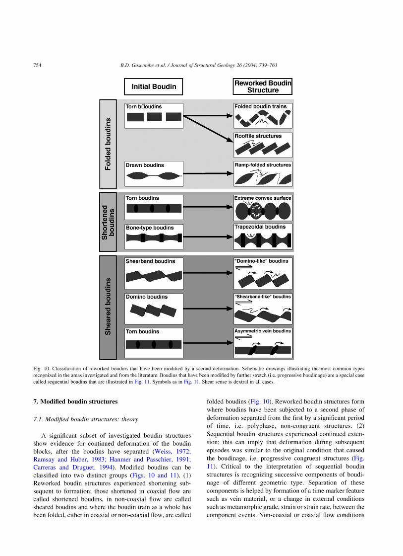
A significant subset of investigated boudin structures
show evidence for continued deformation of the boudin
blocks, after the boudins have separated (Weiss, 1972;
Ramsay and Huber, 1983; Hanmer and Passchier, 1991;
Carreras and Druguet, 1994). Modified boudins can be
classified into two distinct groups (Figs. 10 and 11). (1)
Reworked boudin structures experienced shortening sub-
sequent to formation; those shortened in coaxial flow are
called shortened boudins, in non-coaxial flow are called
sheared boudins and where the boudin train as a whole has
been folded, either in coaxial or non-coaxial flow, are called
folded boudins (Fig. 10). Reworked boudin structures form
where boudins have been subjected to a second phase of
deformation separated from the first by a significant period
of time, i.e. polyphase, non-congruent structures. (2)
Sequential boudin structures experienced continued exten-
sion; this can imply that deformation during subsequent
episodes was similar to the original condition that caused
the boudinage, i.e. progressive congruent structures (Fig.
11). Critical to the interpretation of sequential boudin
structures is recognizing successive components of boudi-
nage of different geometric type. Separation of these
components is helped by formation of a time marker feature
such as vein material, or a change in external conditions
such as metamorphic grade, strain or strain rate, between the
component events. Non-coaxial or coaxial flow conditions
Fig. 10. Classification of reworked boudins that have been modified by a second deformation. Schematic drawings illustrating the most common types
recognized in the areas investigated and from the literature. Boudins that have been modified by further stretch (i.e. progressive boudinage) are a special case
called sequential boudins that are illustrated in Fig. 11. Symbols as in Fig. 11. Shear sense is dextral in all cases.
B.D. Goscombe et al. / Journal of Structural Geology 26 (2004) 739–763754

do influence further extension of boudins, but mainly in the
degree of asymmetry of the structures, which can be
weakened or strengthened in this way.
In the discussion of boudin modification it is important to
realize that not all combinations of shortening and extension
of layers are possible in a flowing continuum. In any type of
monoclinic non-coaxial flow with real eigenvectors, i.e. all
flow types between simple shear and pure shear, material
lines can only rotate from the shortening into the extension
field. This means that during continuous deformation, a
layer may be first shortened and possibly folded, and then
boudinaged, but NOT first boudinaged and then folded. For
this reason, if shortened boudins are found, this is evidence
for either an unusual flow type without real eigenvectors
(rotating flows, like in an eddy), or that deformation is
polyphase, with a change in the orientation of principal
shortening directions between periods of deformation
(Passchier, 1997).
In practice, it may not be possible or useful to determine
exactly what combination of deformation was involved in
the formation of a modified boudin structure. However, in
all cases it is useful to know that such overprints exist, since
they indicate a change in the nature of deformation in an
area. The main purpose of the following descriptions is to
facilitate recognition of modified boudin structures. Some
modified boudins are straightforward to recognize, but
others may closely resemble simple single-phase boudins.
In all cases, crucial information is stored in both the inter-
boudin zone and any enveloping foliations present along the
boudin exterior. In reworked boudin structures, this includes
shortening or folding of inter-boudin vein infill, or solution
or crenulation cleavage development in the inter-boudin
zone or over the boudin exterior (Fig. 10). Similarly, in
sequential boudin structures deformation is typically
partitioned into the inter-boudin zone, which is modified
into more complex forms (Fig. 11). Note that some folding
types can develop as part of the normal boudinage process if
part of the fabric is rotated into the shortening field of local
flow (i.e. kinkbands associated with shearband boudins).
However, such folding will indicate shortening at high angle
to the boudin envelope, not parallel to it.
7.2. Reworked boudin structures: overprinting under
different external conditions
A significant proportion of the boudins noted in the
literature (Weiss, 1972; Ramsay and Huber, 1983; Mala-
vielle and Lacassin, 1988; Hanmer and Passchier, 1991;
Fig. 11. Schematic drawings of the most common sequential boudins recognized in the areas investigated. Sequential boudin structures are the cumulative
result of two or more boudin block geometry components formed during progressive boudinage. Shear sense is dextral in all cases.
B.D. Goscombe et al. / Journal of Structural Geology 26 (2004) 739–763 755

Swanson, 1992; Carreras and Druguet, 1994) and in the
areas investigated, have been modified to varying degrees
by later deformation. In most cases, reworked boudins are
easily recognized as structures with disharmonic folding
(i.e. shortening) of foliations in the enveloping surface (Fig.
10). Alternatively, boudin blocks may be deformed by a
second boudinage event with extension axis at a high angle
to the first, such as chocolate tablet boudins. Examples of
extensional reworking of boudin structures are rare and hard
to distinguish from complex boudin structures that formed
in a single event of high flattening strain (Casey et al., 1983;
Ghosh, 1988; Aerden, 1991) or in triclinic flow.
7.2.1. Folded boudin structures
Modified boudins are typically, though not always, the
result of overprinting subsequent to boudinage by a second,
pervasive deformation event. Obvious examples of
reworked boudin structures are folded boudin trains (Fig.
10) (Ramberg, 1952; Sengupta, 1983). Where aspect ratios
are high, individual boudin blocks may be folded without
folding of the boudin train (Sengupta, 1983). If the boudins
were wide apart, shortening can stack them like shingles
into ‘rooftile’ structures (Sengupta, 1983; Passchier et al.,
1990), and drawn boudins can develop into ‘ramp-folded’
structures (Fig. 10; Passchier et al., 1990; Price and
Cosgrove, 1990). Asymmetric ramp-folded tapering bou-
dins are common in the Kaoko Belt and Damara Orogen in
Namibia, and the Himalayan investigation regions. In all of
these regions, Lb is parallel to fold axes and the reworked
structure apparently formed in one progressive shear event,
suggesting a rotating flow scenario (Passchier et al., 1990)
where boudin trains rotated from the extensional into the
shortening field. Structures with apparent asymmetric ramp-
folded forms can also form by attenuation of the overturned
limb of a fold without earlier boudinage (Swanson, 1999).
7.2.2. Sheared boudin structures
Boudins may also be reworked by non-coaxial flow, not
necessarily with shortening or extension; e.g. when they are
parallel to the flow plane of simple shear or another fabric
attractor. Layer-parallel shear of symmetric boudins pro-
duces asymmetric structures similar to simple asymmetric
boudin types, such as torn boudins that are sheared into
domino-type or shearband-type geometries. If boudins do
not deform much internally, slip on the inter-boudin surface
can modify torn boudins into shapes resembling domino
boudins. If the boudins do deform internally, shearband
boudin shapes can result from either drawn or torn boudins.
Torn boudins with inter-boudin vein material result in what
we call ‘asymmetric vein boudins’ that superficially
resemble simple dilational domino boudins (Figs. 10 and
12d). These have been called ‘asymmetric bone-type
boudins’ and have been shown to result from layer-parallel
shear rotating the inter-boudin veins into a consistently
inclined array (Malavielle and Lacassin, 1988; Swanson,
1992). Extreme layer-parallel shear may result in foliation-
oblique boudin trains of the earlier formed inter-boudin vein
material (Swanson, 1999).
Layer-parallel shear of asymmetric boudin types can
change boudin shape by rotation of Sib into either steeper or
shallower inclinations and by internal deformation of the
boudin blocks (Fig. 10). In high strain, high metamorphic
grade ductile terranes, layer-parallel shear can result in the
two asymmetric boudin types being oppositely modified and
the geometry of the two converging towards each other. For
example, layer-parallel shear rotates Sib into lower incli-
nations (i.e. u and u0 decrease) in domino boudins, resulting
in what we call ‘shearband-like’ boudins. Conversely, Sib
steepens in shearband boudins resulting in ‘domino-like’
boudins (Fig. 10). Consequently, in high shear-strain, high-
grade terranes, domino and shearband boudins may be
incorrectly identified and caution must be employed when
using these as shear sense indicators (Goscombe and
Passchier, 2003). All these examples of sheared boudin
structures can potentially look like a simple end-member
boudin type and be almost impossible to recognize as
reworked boudin structures that experienced polyphase
histories. The complex history recorded by the final
reworked boudin structure is best indicated by disharmonic
folding of the enveloping surface (Fig. 10) and folding of
internal layering within boudin blocks (Fig. 12d).
7.2.3. Shortened boudin structures
Shortening by coaxial flow, i.e. symmetric shortening of
a layer, results in the most spectacular changes in shape of
boudins. If they do not deform much internally, torn boudins
can be shortened by compressing the inter-boudin zone,
leading to folding of the enveloping foliation that had been
drawn into the gap (Fig. 12e). In extreme cases, it can lead to
extrusion of foliated matrix material or vein infill out of the
inter-boudin zone. In the case of drawn boudins, the thin
inter-boudin neck can be folded or affected by pressure
solution seams. If folded, the thinnest portion of the neck
will show the smallest wavelength of folding as predicted by
buckling theory (Ramsay, 1967). If the boudins deform
internally, barrel-shaped or blocky boudins may obtain
markedly rounded bi-convex exteriors with high Bb ratios,
resulting in a curious oval shape with a barrelling effect that
is more extreme than anything developed in normal boudins
(Fig. 12f). Barrelling such as this is easily recognized where
boudin width is significantly greater than the relict
undeformed inter-boudin vein material (Fig. 12e and f).
Alternatively, shortening of boudins with either parallel or
bi-concave exteriors, such as bone-type boudins, will result
in ‘trapezoidal boudins’ if initial boudin block aspect ratios
were low (Sengupta, 1983; Fig. 10). Symmetric shortening
of asymmetric boudins can lead to reverse faulting
reactivation of Sib, and if the boudins are deforming
internally, into less asymmetric shapes that may be difficult
to recognize as having been reworked. In all cases,
foliations and lineations that mantle the boudin train will
be shortened and can show the effects of this shortening by
B.D. Goscombe et al. / Journal of Structural Geology 26 (2004) 739–763756

Fig. 12. Examples of modified boudins. Sequential boudin structures ((a)–(c)) are special cases of modified boudins that are formed by progressive stretching
resulting in temporally sequential components of different boudin block geometries. (a) Torn boudin with classic barrel boudin geometry of concave face and
convex exterior, in mafic gneiss from the Kaoko Belt, Namibia. Progressive boudinage resulted in drawn boudinage of the inter-boudin zone vein infill
resulting in an overall tapering boudin geometry. (b) Psammite layer with straight-face torn boudins and quartz-vein infill in the inter-boudin zone, from the
Gander Zone in Newfoundland. Progressive boudinage and a change in competence hierarchy resulted in extreme flattening of the original boudin blocks that
were drawn without modification of the more competent inter-boudin vein infill. (c) Original domino boudins widely separated by drawn boudinage at higher
ductility. Example is in high metamorphic grade quartzo-feldspathic gneisses from the Kaoko Belt in Namibia. Reworked boudin structures (d)–(f). (d)
Straight-face torn boudins in a psammite layer from the Ugab Zone, Namibia, have been modified by sinistral foliation-parallel shear. Quartz veins in the inter-
boudin zones have been rotated into a consistently inclined array and boudin blocks have been folded in sympathy with the asymmetric tightening of scar folds
in the host. (e) Sequential boudin structure from the Ugab Zone, Namibia, that involved progressive boudinage of carbonate layers. Straight-face torn boudins
with vein infill were subsequently drawn into tapering boudin geometries. The sequential boudin structures were later modified by shortening along the length
of the boudin train, producing thickening and folding of the boudin blocks. (f) Mafic concave-face torn boudins with quartz-vein infill in the inter-boudin zone,
from Mount Isa in Australia. The boudin train was later modified by roughly layer-parallel shortening, resulting in thickening of the boudin blocks, producing
extreme convex curvature of the exterior. The inter-boudin vein infill provides an approximate indication of the original layer width.
B.D. Goscombe et al. / Journal of Structural Geology 26 (2004) 739–763 757

the development of solution seams, crenulation cleavage,
small folds or kinks. Crucially, the scar folds in the
inter-boudin zone differ in shortened boudin trains by
having greatly enhanced amplitudes and tight, pinched
hinges (Fig. 12f).
7.3. Sequential boudin structures: overprinting under
similar external conditions
Sequential boudin structures are complex boudin struc-
tures that evolved through progressive deformation at
similar conditions to those in the initial stages of boudinage.
That is, they form by continuing stretch of the boudinaged
material and document the ontogenesisof the structure from
initiation to an ‘adult’ boudin form. Simple end-member
boudin block geometries (Fig. 2a) themselves constitute the
simplest category of sequential boudin structures, because
they are not instantaneously formed. Examples of such
gradual modification of boudin shape during one phase of
progressive deformation are: (1) the development of domino
boudins from a near-orthogonal crack in a layer that
develops further by rotation and/or some internal defor-
mation, e.g. that associated with the development of
flanking folds (Goscombe and Passchier, 2003); (2)
forked-gash and sigmoidal-gash boudins initiate as orthog-
onal cracks and develop by boudin separation and the inter-
boudin vein can either curve (sigmoidal-gash) or branch
(forked-gash) at its tips (Goscombe and Passchier, 2003);
and (3) concave-face boudins have variably developed
‘burring’ over the boudin edge resulting in barrel boudins
and, with increasing strain, fishmouth boudins and false-
isoclinal folds. This is due to the maximum stress being
concentrated on the boudin edges, resulting in internal
deformation of the boudin block (Lloyd et al., 1982).
More typically, sequential boudin structures record
components of different end-member boudin geometries,
superimposed in a temporal sequence (Table 2; Fig. 11).
Sequential boudins are a special case of modified boudins,
involving progressive stretch of the layer, resulting in what
can be considered boudinage-modified boudins. Eleven
percent of all investigated boudins are sequential boudins.
In all examples investigated, there is no evidence for
sequential boudins being the result of reworking by
subsequent deformational events. All boudin components
maintain the same extension axis (Le) and are consistent
with progressive stretch in a single deformation event.
Considering the four most common end-member boudin
geometry types (drawn, shearband, domino and torn), there
are 12 possible permutations of sequential boudins invol-
ving two different boudin components. Nine of these have
been recorded in our dataset of natural boudin structures;
some of these are documented below and their frequency is
presented in Appendix B (this can be found in the online
version of this paper).
The most common sequence is from a torn boudin
component to a drawn boudin component by symmetric
extension of a symmetric form (Appendix B). Possibly, this
documents either a progression to lower strain rate or
prograde metamorphism, and thus more ductile defor-
mation. For example, bow-tie vein (DePaor et al., 1991) and
bone-type boudins (Price and Cosgrove, 1990; Swanson,
1992; Fig. 12b) are sequential boudins with an early torn
boudin and vein infill component, followed by drawn
boudinage of either the inter-boudin vein (Hossein, 1970) or
boudin block resulting in these two respective types (Fig.
11). Bone-type boudins develop where the vein material is
stronger than the boudin material, resulting in subsequent
extension being partitioned into the boudin block, which is
stretched. Eight percent of torn boudins in the Kaoko Belt
are bow-tie vein boudins (Figs. 3 and 12a); these structures
have been noted elsewhere by previous workers (DePaor
et al., 1991; Ramsay and Lisle, 2000). In these structures,
the W0W ratio of the stretched inter-boudin vein averages
0.54 and is intermediate between torn boudins (W0W ¼ 1)
and necked boudins (W0W averaging 0.38; Fig. 11).
Evidence of a progression from symmetric to asymmetric
boudinage components, such as torn boudins with a later
domino boudin component (Swanson, 1992) or shearband
boudin component (‘intermediate’ boudinage of Lacassin
(1988); Fig. 11; Appendix B) is also common. In a few
sequential boudins, a third component can be recognized,
such as domino boudinage of a previously thinned, bow-tie
vein boudin (Fig. 11). The opposite, where dilational
domino boudins undergo symmetric necking of the inter-
boudin vein material, has been modelled in progressive
boudinage by Hossein (1970). In the high metamorphic
grade areas investigated in the Kaoko Belt, the progression
from asymmetric to symmetric boudinage components is
common. Domino boudins commonly experienced later
extreme ductile stretch—either symmetric (tapering bou-
dinage) or slightly asymmetric (shearband boudinage)—
resulting in trains of widely isolated rhomb-shaped boudin
blocks (Fig. 11). We have called these ‘asymmetric-
tapering’ boudins. In all investigated cases, the vergence
of Sib inclination with respect to bulk shear sense and the
high u angles preserved are consistent with their initial
formation as domino boudins (Fig. 12c). Asymmetric-
tapering sequential boudins are apparently restricted to high
strain, high metamorphic grade ductile terranes.
8. Multiple boudinage events
In all the multiply deformed terranes investigated
(Kaoko Belt, Ugab Terrane, Zambezi Belt and Adelaidean
Fold Belt), it has been found that boudinage occurred in
more than one deformation event. In these terranes, the
vast majority of boudins formed early (88% in the Kaoko
Belt), during a deformation event that produced a
regionally pervasive penetrative fabric, and a minor
group of boudins with different orientation formed in a
later deformation event. No cases were recorded of
B.D. Goscombe et al. / Journal of Structural Geology 26 (2004) 739–763758

boudinage from two distinct deformation events being
superimposed to produce one complex boudin structure.
Given the possibility of multiple boudinage events, where
boudins are employed as shear sense indicators, flow
regime indicators, or indicators of the maximum exten-
sion direction (Goscombe and Passchier, 2003), each
boudin structure must be correctly correlated with the
appropriate deformation event.
Correlation of boudin structure and deformation event is
possible because Le, the theoretical stretching axis associ-
ated with boudinage (normal to Lb within Se; Appendix A),
typically has a regular orientation and is both sub-parallel to
and symmetrically distributed around the stretching linea-
tion (Lp) produced during the same deformation event
(Goscombe and Passchier, 2003). The angle between Lp and
Lb (d;Appendix A) has maximum frequency at 908
(Goscombe and Passchier, 2003). Consequently, Le is a
useful kinematic indicator approximating the axis of
maximum finite stretch. Where there are discrete orientation
populations of Lb (and by inference also Le), these could be
used to define multiple boudinage events. Where boudins
are developed, Le may be the only kinematic indicator
available to define the stretching axis in low-grade, low-
strain or fine-grained terranes that are otherwise devoid of
stretching lineations. Conversely, in terranes with mineral
lineations developed, boudin structures can be employed to
test if these mineral lineations are indeed stretching
lineations.
9. Conclusions
From this analysis of natural boudin structures, it can be
concluded that all simple unmodified boudin structures can
be fully classified by considering boudin block geometry,
boudin train obliquity and material layeredness as summar-
ized graphically in Appendix C (this can be found in the
online version of this paper). The entire range of natural
boudin block geometries can be rationalized in terms of only
five distinctive end-members: drawn, torn, gash, domino
and shearband boudins (Fig. 3). The process of boudinage
takes place in each case by only one of three mutually
exclusive kinematic classes: no-slip, antithetic slip (A-slip)
and synthetic slip boudinage (S-slip). Each of these three
kinematic classes corresponds almost exclusively to specific
boudin block geometries (Table 1). All drawn and torn
boudins form by no-slip boudinage, gash and domino
boudins by A-slip boudinage and shearband boudins by S-
slip boudinage (Goscombe and Passchier, 2003). Tran-
sitions between end-member boudin block geometries are
recognized in individual geometric parameters (Figs. 2 and
6–8; Table 2). Nevertheless, when the full suite of
quantitative geometric parameters and qualitative features
are considered, the end-member boudin block geometries
remain distinct groupings that are recognizable in the field.
We feel that the classification scheme outlined and the
following kinematic conclusions are generally applicable as
they are based on a comprehensive set of observations and
data, from microscopic to macroscopic scales and a wide
range of geological settings, flow regimes, rock types and
metamorphic grades.
Previous work has resulted in a number of kinematic
conclusions with regard to boudins and flow, and these are
dependent on the classification scheme outlined here. (1)
Given that both the boudin block geometry and an
approximation of the fabric attractor can be identified, it
has been shown that all boudin geometries in foliation-
oblique boudin trains and asymmetric boudins in foliation-
parallel boudin trains (Table 2) can be employed as practical
and reliable shear sense indicators (Goscombe and Passch-
ier, 2003). (2) It is widely recognized that the near
coincidence of the boudin extension axis (Le) with a
mineral stretching lineation (Lp) in many host rocks
suggests boudin structures can be used to constrain the
stretching axes (transport direction in monoclinic flow) in
orogens devoid of mineral stretching lineations, such as in
fine-grained, low-strain or low metamorphic-grade terranes
(Goscombe and Passchier, 2003).
An important result of the work shown here is that
multiple generations of boudins, sequential boudin
structures and reworked boudin structures, all record the
strain history of a rock mass. Unlike deformation fabrics,
boudins are difficult to completely rework and obliterate;
thus multiple boudin generations can preserve palaeo-
stretching axis directions from different deformational
episodes. The suite of boudin types developed during
different deformational episodes, and indeed between
different study areas, is often distinct. If future workers
draw correlations between boudin-type and flow regime,
as seems to be the case, boudins may prove useful as
indicators of flow regime during different deformational
episodes and in characterizing different terranes (e.g.
Passchier and Druguet, 2002).
Acknowledgements
Drs Roy Miller, Rudolph Trouw, Fabio Pentagna,
Andre Ribeiro, Chris Wilson, Thomas Bekker, Dave Gray
and Pat James as well as David and Audrey Goscombe,
Helmut Garoeb, Zigi Baugartner, Pete and Alex Siegfried,
Murray Haseler and Bonza, are all thanked for their
discussions, efforts spying out elusive boudins and great
company in the field. The constructive reviews and efforts
of Dr L. Goodwin and J. Hippertt were greatly
appreciated. This study resulted from regional mapping
work undertaken for the Namibian Geological Survey and
self-funded fieldwork elsewhere. Mimi Duneski is sin-
cerely thanked for her considerable administrative support
and humour in Namibia.
B.D. Goscombe et al. / Journal of Structural Geology 26 (2004) 739–763 759

Appendix A. Definition of boudin structural elements
and geometric parameters (Fig. 1)
Regional fabric elements
Sp Penetrative foliation formed in host
rock during deformation associated
with boudinage.
Lp Stretching lineation in host rock, for
simplicity, considered vector of relative
transport during deformation associated
with boudinage. Reference frame for
linear boudin parameters.
Se Enveloping surface of boudinaged layer,
equivalent to the overall trace of the
boudin train. In most cases parallel to Sp
(i.e. foliation-parallel boudin trains) but
can be oblique to Sp in the case of
foliation-oblique boudin trains. Refer-
ence frame for planar boudin parameters
Le Extension axis defined by boudin struc-
ture. Line normal to the long axis of
boudin (Lb), in Se plane. It is usually
close to the X-axis of the finite strain
ellipsoid and typically sub-parallel to
the stretching lineation (Lp) when
developed.
Shear sense Bulk shear sense during deformation
associated with boudinage. Reference
frame for all rotational and movement
parameters in boudin structures.
Defined by C0- and C-type shear band
cleavages (Simpson, 1984; Lister and
Snoke, 1984), s-type and d-type por-
phyroclasts (Passchier and Simpson,
1986) and flanking folds (Hudleston,
1989; Passchier, 2001).
Profile plane Plane normal to both long axis of
boudin (Lb) and Se. Boudins with
monoclinic symmetry are viewed and
parameters are measured in this plane.
In cases of triclinic boudin symmetry,
the Se surface is also used as an
additional, orthogonal plane of view.
Fabric attractor Hypothetical plane or line in rock mass,
towards which material lines and planes
rotate with progressive deformation
(Passchier and Trouw, 1996; Passchier,
1997).
Boudin nomenclature and structural elements
Boudin block Separate elongate body of rock that
originated from boudinage of a layer,
object or foliation planes. A string of
boudin blocks originating from one
layer comprise a boudin train.
Inter-boudin zone Elongate zone between the edges of
adjacent boudin blocks.
Boudin edge Intersection of a planar boudin face
(Sib) and boudin exterior (Sb); parallel
to the long axis of both boudin blocks
(Lb) and inter-boudin zones.
Lb Long axis of boudin; equivalent to the
“neck line” (Hobbs et al. 1976). This
line is usually parallel to the intermedi-
ate axis (Y) of the finite strain ellipsoid.
Equivalent to intersection between Sib
and Sb surfaces, that is, the boudin edge
(Fig. 1).
Lb vergence Vergence of acute angle between Lb and
stretching lineation (Lp); either clock-
wise or anticlockwise from the stretch-
ing lineation in the Se surface.
Sb Boudin exterior; original surface of
boudin block in contact with host.
Block rotation Sense of relative rotation of individual
boudin blocks, with respect to bulk
shear sense.
Boudin face Lateral end of boudin block adjacent to
others in boudin train, typically a planar
or termination face (equivalent to Sib) or
a point termination in drawn boudins
Sib Inter-boudin surface; defined as the
median plane in the inter-boudin zone,
at moderate to high angle to Se. In
asymmetric boudin structures, is typi-
cally a single discrete surface that
experienced lateral displacement of
adjacent boudins. The Sib surface does
not propagate beyond the boudinaged
layer (in contrast to faults or shear
zones) and in asymmetric boudins, arcs
into the enveloping surface at the
boudin edge. In torn boudins, Sib is
typically equivalent to the terminal face
of the boudin block. No Sib is developed
in drawn boudins, thus an arbitrary
“Sib” is defined as the plane connecting
boudin terminations, parallel and
median to the extensional mobile zone
that is the neck (Fig. 4c).
Lib Vector of movement within Sib, rarely
expressed as slickenlines or mineral
elongation lineations.
Slip sense Sense of lateral displacement along Sib,
with respect to bulk shear sense.
Sib vergence There are two types of vergence of Sib
with respect to bulk shear sense: (1)
Spiral vergence, analogous to sygmoi-
dal tension gashes, and (2) Direction of
inclination of Sib with respect to bulk
shear sense; those inclined in opposite
direction to shear sense are named
forward-vergent and those inclined in
B.D. Goscombe et al. / Journal of Structural Geology 26 (2004) 739–763760

the same direction as shear sense are
named backward-vergent. These are
equivalent to “forward-tilted” and
“backward-tilted” respectively (Swan-
son 1992), which are defined by an
imagined tilting of Sib from an orig-
inally orthogonal orientation, with
respect to bulk shear sense. In the case
of gash boudins, both types of vergence
are observed on both the profile and Se
planes of view.
“Drag” on Sib Sense of apparent drag on boudin face,
with respect to slip sense. Can be either
antithetic (flanking folds) or synthetic
(flanking shear band; Fig. 5; Passchier,
2001). Flanking folds on Sib contribute
an additional component of block
rotation that is synthetic with whole
block rotation. Flanking folds on Sib are
not to be confused with the flanking
folds that formed by similar mechan-
ism, but of different scale and site, on
the margin of the trace of foliation-
oblique boudin trains (Fig. 5).
Angular parameters
d Acute angle between Lp and Lb, an
approximate measure of the degree of
departure from monoclinic symmetry.
A boudin structure of monoclinic sym-
metry has d = 908.
a Relative block rotation; is the acute
angle between Se and Sb.
u Acute angle between Sb and Sib;
quantifying boudin block shape.
u0 Acute angle between Sib and Se; quanti-
fying Sib inclination in outcrop:
u0 ¼ u 2 a.
b Angle between Sib and axial surface of
associated kinkbands. Measured from
Sib synthetic with respect to slip sense
on Sib, and so may be acute or obtuse.
C Obliquity of boudin train; measured as
the angle between Se and the fabric
attractor, which is assumed in most
cases to approximate the penetrative
foliation (Sp).
Dimensional parameters
W Width or thickness of boudinaged layer.
W0 Minimum width of thinned layer or vein
infill in the inter-boudin zone.
L Length of boudin blocks in the profile
plane.
Q Extent of the boudin block parallel to
Lb. Typically greater than the extent of
the outcrop and thus effectively infinite.
M Component of extension of boudinaged
layer, parallel to Se and normal to Lb.
Measured between boudin edges in
asymmetric and torn boudins and
between inflection points (Penge,
1976) in the termination or neck zone
of drawn boudins (Fig. 1d).
M0 Degree of isolation of adjacent boudin
blocks, parallel to Se and normal to Lb.
Equivalent to “gap length” (Lloyd et al.,
1982). M0 , M in asymmetric boudins
and M0 ¼ M is only possible in sym-
metric boudins.
N Amount of dilation normal to, and
across, Sib. Not applicable to drawn
boudins with arbitrary “Sib”, minor for
asymmetric boudins and significant in
torn boudins where with N ø M ø M0.
D Lateral displacement along Sib between
adjacent boudin blocks.
Stretch Percent extension of the enveloping
surface (Se): Stretch ¼ 100(M þ
Lcosa)/L. Considers the extension of a
line (Se), not a layer of finite width, thus
stretch can only be considered mini-
mum value of layer extension and
stretch ,100% can occur for low M
and high a boudins.
Bb Ratio describing the curve of the boudin
exterior (Fig. 4). Defined by the height
above (þve) or below (2ve) the line
between boudin edges, divided by
length of the straight line between
edges (i.e. L).
Bf Ratio describing the curve of the boudin
face (Fig. 4). Defined by the distance
out (þve) or into the boudin block
(2ve) from the line between boudin
edges, divided by the straight line
length of this face line.
References
Aerden, D.G.A.M., 1991. Foliation-boudinage control on the formation of
the Rosebery Pb–Zn orebody, Tasmania. Journal of Structural Geology
13, 759–775.
Blumenfeld, P., 1983. Le “tuilage des megacristaux”, un critere d’ecoule-
ment rotationnel pour les fluidalites des roches magmatiques;
Application au granite de Barbey. Bulletin de la Societe geologique
de France 25, 309–318.
Borradaile, G.J., Bayly, M.B., Powell, C.McA., 1982. Atlas of Deforma-
tional and Metamorphic Rocks Fabrics, Springer-Verlag, Berlin,
Heidelberg, New York, 649pp.
Bosworth, W., 1984. The relative roles of boudinage and ‘structural slicing’
in the disruption of layered rock sequences. Journal of Geology 92,
447–456.
Carreras, J., Druguet, E., 1994. Structural zonation as a result of
B.D. Goscombe et al. / Journal of Structural Geology 26 (2004) 739–763 761

inhomogeneous non-coaxial deformation and its control on syntectonic
intrusions: an example from the Cap de Creus area, eastern-Pyrenees.
Journal of Structural Geology 16, 1525–1534.
Casey, M., Dietrich, D., Ramsay, J.G., 1983. Methods for determining
deformation history for chocolate tablet boudinage with fibrous
crystals. Tectonophysics 92, 211–239.
Conti, P., Funedda, A., 1998. Mylonite development in the Hercynian
basement of Sardinia (Italy). Journal of Structural Geology 20,
121–133.
Daniel, J.-M., Jolivet, L., Goffe, B., Poinssot, C., 1996. Crustal-scale strain
partitioning: footwall deformation below the Alpine Oligo–Miocene
detachment of Corsica. Journal of Structural Geology 18, 41–59.
Davis, G.H., 1987. A shear-zone model for the structural evolution of
metamorphic core complexes in southeastern Arizona. Continental
Extensional Tectonics, Geological Society Special Publication 28,
247–266.
DePaor, D.G., Simpson, C., Bailey, C.M., McCaffrey, K.J.W., Bean, E.,
Gower, R.J.W., Aziz, G., 1991. The role of solution in the formation of
boudinage and transverse veins in carbonate rocks at Rheems,
Pennsylvania. Geological Society of America Bulletin 103,
1552–1563.
Etchecopar, A., 1974. Simulation par ordinateur de la deformation
progressive d’un aggregat polycrystallin. Etude du developpement de
structures orientees par ecrasement et cisaillement. Unpublished Ph.D.
thesis, University of Nantes, France.
Etchecopar, A., 1977. A plane kinematic model of progressive deformation
in a polycrystalline aggregate. Tectonophysics 39, 121–139.
Fry, N., 1984. The Field Description of Metamorphic Rocks, Geological
Society of London Handbook Series, Open University Press, Milton
Keynes, 110pp.
Ghosh, S.K., 1988. Theory of chocolate tablet boudinage. Journal of
Structural Geology 10, 541–553.
Ghosh, S.K., Sengupta, S., 1999. Boudinage and composite boudinage in
superimposed deformations and syntectonic migmatization. Journal of
Structural Geology 21, 97–110.
Goldstein, A.G., 1988. Factors affecting the kinematic interpretation of
asymmetric boudinage in shear zones. Journal of Structural Geology 10,
707–715.
Goscombe, B., 1991. Intense non-coaxial shear and the development of
mega-scale sheath folds in the Arunta Block, Central Australia. Journal
of Structural Geology 13, 299–318.
Goscombe, B., 1992. High-grade reworking of central Australian
granulites. Part 1. Structural evolution. Tectonophysics 204, 361–399.
Goscombe, B., Everard, J.L., 2000. Tectonic evolution of Macquarie
Island: extensional structures and block rotations in oceanic crust.
Journal of Structural Geology 23, 639–673.
Goscombe, B., Passchier, C.W., 2003. Asymmetric boudins as shear sense
indicators—an assessment from field data. Journal of Structural
Geology 25, 575–589.
Grasemann, B., Stuwe, K., 2001. The development of flanking folds during
simple shear and their use as kinematic indicators. Journal of Structural
Geology 23, 715–724.
Hanmer, S.K., 1984. The potential use of planar and elliptical structures as
indicators of strain regime and kinemetics of tectonic flow. Current
Research, Part B, Geological Survey of Canada, Paper 84-1B, pp. 133–
142.
Hanmer, S., 1986. Asymmetrical pull-aparts and foliation fish as kinematic
indicators. Journal of Structural Geology 8, 111–122.
Hanmer, S., 1989. Initiation of cataclastic flow in a mylonite zone. Journal
of Structural Geology 11, 751–762.
Hanmer, S., Passchier, C., 1991. Shear-Sense Indicators: A Review.
Geological Survey of Canada. Paper 90-17, 72pp.
Hobbs, B.E., Means, W.D., Williams, P.F., 1976. An Outline of Structural
Geology. John Wiley and Sons, 278–280.
Hossein, K.M., 1970. Experimental work on boudinage. Unpublished M.Sc.
thesis, Imperial College, University of London.
Hudleston, P.J., 1989. The association of folds and veins in shear zones.
Journal of Structural Geology 11, 949–957.
Jones, A.G., 1959. Vernon map-area British Columbia. Memoir Geological
Survey Branch, Canada 296, 1–186.
Kraus, J., Williams, P.F., 1998. Relationships between foliation develop-
ment, porphyroblast growth and large-scale folding in the metaturbidite
suite, Snow Lake, Canada. Journal of Structural Geology 20, 61–76.
Lacassin, R., 1988. Large-scale foliation boudinage in gneisses. Journal of
Structural Geology 10, 643–647.
Laubach, S.E., Reynolds, S.J., Spencer, J.E., 1989. Progressive deformation
and superposed fabrics related to Cretaceous crustal underthrusting in
western Arizona, USA. Journal of Structural Geology 11, 735–749.
Lisle, R., 1996. Cover photograph. Journal of Structural Geology 18.
Lister, G.S., Snoke, A.W., 1984. S–C mylonites. Journal of Structural
Geology 6, 617–638.
Lloyd, G.E., Ferguson, C.C., 1981. Boudinage structure: some new
interpretations based on elastic–plastic finite element simulations.
Journal of Structural Geology 3, 117–128.
Lloyd, G.E., Ferguson, C.C., Reading, K., 1982. A stress-transfer model for
the development of extension fracture boudinage. Journal of Structural
Geology 4, 355–372.
Lohest, M., 1909. L’origine des veines et des geodes des terrains primaires
de Belgique. Annales de la Societe geologique Belgique 36B, 275–282.
Malavielle, J., Lacassin, R., 1988. ‘Bone-shaped’ boudins in progressive
shearing. Journal of Structural Geology 10, 335–345.
Mandal, N., Karmakar, S., 1989. Boudinage in homogeneous foliation
rocks. Tectonophysics 170, 151–158.
Mullenax, A.C., Gray, D.R., 1984. Interaction of bed-parallel stylolites and
extension veins in boudinage. Journal of Structural Geology 6, 63–71.
Passchier, C.W., 1997. The fabric attractor. Journal of Structural Geology
19, 113–127.
Passchier, C.W., 2001. Flanking structures. Journal of Structural Geology
23, 951–962.
Passchier, C.W., Druguet, E., 2002. Numerical modelling of asymmetric
boudinage. Journal of Structural Geology 24, 1789–1804.
Passchier, C.W., Simpson, C., 1986. Porphyroclast systems as kinematic
indicators. Journal of Structural Geology 8, 831–843.
Passchier, C.W., Myers, J.S., Kroner, A., 1990. Field Geology of High-
Grade Gneiss Terrains, Springer-Verlag, Berlin, 150pp.
Penge, J., 1976. Experimental deformation of pinch-and-swell structures.
Unpublished M.Sc. thesis, Imperial College, University of London.
Price, N.J., Cosgrove, J.W., 1990. Analysis of Geological Structures,
Cambridge University Press, Cambridge.
Ramberg, H., 1952. The Origin of Metamorphic and Metasomatic Rocks,
University of Chicago Press, Chicago.
Ramsay, A.C., 1881. The Geology of North Wales. Memoirs of the
Geological Survey of Great Britain, 3.
Ramsay, J.G., 1967. Folding and Fracturing of Rocks, McGraw-Hill, New
York, pp. 103–109.
Ramsay, J.G., Huber, M.I., 1983. The Techniques of Modern Structural
Geology. Volume 1: Strain Analysis, Academic Press, London, pp.
1–224.
Ramsay, J.G., Huber, M.I., 1987. The Techniques of Modern Structural
Geology. Volume 2: Folds and Fractures, Academic Press, London, pp.
516–633.
Ramsay, J.G., Lisle, R., 2000. The Techniques of Modern Structural
Geology. Volume 3: Application of Continuum Mechanics in Structural
Geology, Academic Press, London.
Roig, J.-Y., Faure, M., Truffert, C., 1998. Folding and granite emplacement
inferred from structural, strain, TEM and gravimetric analyses: the case
study of the Tulle antiform, SW French Massif Central. Journal of
Structural Geology 20, 1169–1189.
Sengupta, S., 1983. Folding of boudinaged layers. Journal of Structural
Geology 5, 197–210.
Simpson, C., 1984. Borrego Springs–Santa Rosa mylonite zone: a Late
Cretaceous west-directed thrust in southern California. Geology 12, 8–11.
Simpson, C., Schmid, S.M., 1983. An evaluation of criteria to deduce the
B.D. Goscombe et al. / Journal of Structural Geology 26 (2004) 739–763762

sense of movement in sheared rocks. Bulletin of the Geological Society
of America 94, 1281–1288.
Swanson, M.T., 1992. Late Acadian–Alleghenian transpressional defor-
mation: evidence from asymmetric boudinage in the Casco Bay area,
coastal Maine. Journal of Structural Geology 14, 323–341.
Swanson, M.T., 1999. Kinematic indicators for regional dextral shear along
the Norumbega fault system in the Casco Bay area, coastal Maine.
Geological Society of America Special Paper 331, 1–23.
Van der Molen, I., 1985. Interlayer material transport during layer-normal
shortening. Part II. Boudinage, Pinch-and-swell and migmatite at
Sondre Stromfjord Airport, West Greenland. Tectonophysics 115,
297–313.
Weiss, L.E., 1972. The Minor Structures of Deformed Rocks, Springer-
Verlag, Berlin, 431pp.
Wilson, G., 1961. The tectonic significance of small-scale structures and
their importance to the geologist in the field. Annals of the Society of
Geologists de Belgique 84, 424–548.
Yamamoto, H., 1994. Kinematics of mylonitic rocks along the Median
Tectonic Line, Akaishi Range, central Japan. Journal of Structural
Geology 16, 61–70.
B.D. Goscombe et al. / Journal of Structural Geology 26 (2004) 739–763 763