bottom ash conversion paper
TRANSCRIPT

8/22/2019 Bottom Ash Conversion Paper
http://slidepdf.com/reader/full/bottom-ash-conversion-paper 1/18
BOTTOM ASH CONVERSIONOPTIONS AND ECONOMICS
Authors:
Criag H. Fleming, Gary D. Mooney
Clyde Bergemann Delta Ducon, Malvern, PA 19355 USA

8/22/2019 Bottom Ash Conversion Paper
http://slidepdf.com/reader/full/bottom-ash-conversion-paper 2/18
BOTTOM ASH CONVERSION OPTIONS AND ECONOMICS 2
INTRODUCTION
Wet Bottom Ash material handling systems and surface impoundments are presentlyregarded as the industry standard and are certainly the most commonly used method inthe coal fired power industry around the world today. However, with the recent event of an ash pond (surface impoundment) failure and the ensuing EPA investigation of allexisting facilities employing this technology, environmentally suitable alternatives arebeing investigated by coal fired electric power producers.
This paper will address the available technologies and their comparison. The fourprimary Bottom Ash conversion approaches are as follows:
DRYCON™ SYSTEM: (retrofit) The collection, crushing, air cooling and
mechanical conveying of bottom ash without the need for water quenching.
SUBMERGED SCRAPER CONVEYOR: (retrofit) The collection, water quenchingand mechanical conveying of bottom ash; with a closed loop cooling water system.
CONVENTIONAL TANK FARM DEWATERING: The continued collection of bottom ash in water impounded hoppers, and the future addition of dewateringbins, settling tank and surge tank; with a closed loop water system.
ASHCON™ REMOTE SUBMERGED SCRAPER CONVEYOR SYSTEM: Thecontinued collection of bottom ash in water impounded hoppers, and the future
addition of a hybrid Submerged Scraper Conveyor; with a closed loop watersystem.
This paper will detail the following for each of the four conversion options:
Site Specific Limitations: Facility Age, Physical Layout, and Boiler design type andconfiguration.
System Design Parameters: Thermal and Mechanical.
Environmental Issues and Benefits: Zero water discharge and Boiler Efficiency
improvement.
Economic analysis, of each approach.
Conversion projects will differ from plant to plant and variations on the systems will bediscussed.
Clyde Bergemann is recognized as a technical leader in the field of Bottom Ash and FlyAsh Handling Systems and has many reference installations around the world.

8/22/2019 Bottom Ash Conversion Paper
http://slidepdf.com/reader/full/bottom-ash-conversion-paper 3/18
BOTTOM ASH CONVERSION OPTIONS AND ECONOMICS 3
Wet Bottom Ash (BA) material handling systems and surface impoundments arepresently regarded as the industry standard and are certainly the most commonly usedmethod in the coal fired power industry around the world today.
Water impounded bottom ash hoppers,located under the boiler throat are used tostore the collected bottom ash andperiodically (once or twice per 8 hour shift)the hoppers are discharged and BottomAsh is hydraulically conveyed to surfaceimpoundments (ash ponds). The ash ispumped utilizing either high pressure jetpumps or slurry pumps.
Surface Impoundment are large water filled basins,either man made or constructed using naturaltopography and the employment of a retainagedam, to store the coal combustion residuals (CCR)for extended periods of time.
At the time when many surface impoundmentswere constructed there was little state or federalregulation.
However, with the recent event of an ash pond(surface impoundment) failure and the ensuingEPA investigation of all existing facilitiesemploying this technology, environmentallysuitable alternatives are being investigated bycoal fired electric power producers.
As of the date of preparation of this paper, therewere 162 Power Plants utilizing Surface
Impoundments. Recently the US EPA isproposing to regulate CCR under one of twoscenarios.
high water level
normal water level
mean ash level
jettin g nozzles
sluice gate &access door
clinker
grinder
weir box high pressure
water inlet jet pump /eductor
Figure 1: Typical Bottom Ash Hopper Arrangement
Figure 2: Typical Surface Impoundment(Ash Pond)
Figure 3: Typical Surface Impoundment after berm failure
8/22/2019 Bottom Ash Conversion Paper
http://slidepdf.com/reader/full/bottom-ash-conversion-paper 4/18
BOTTOM ASH CONVERSION OPTIONS AND ECONOMICS 4
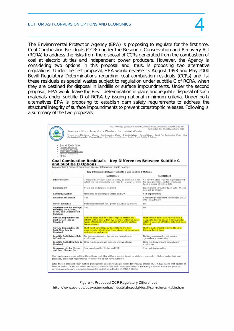
The Environmental Protection Agency (EPA) is proposing to regulate for the first time,Coal Combustion Residuals (CCRs) under the Resource Conservation and Recovery Act(RCRA) to address the risks from the disposal of CCRs generated from the combustion of coal at electric utilities and independent power producers. However, the Agency isconsidering two options in this proposal and, thus, is proposing two alternativeregulations. Under the first proposal, EPA would reverse its August 1993 and May 2000Bevill Regulatory Determinations regarding coal combustion residuals (CCRs) and listthese residuals as special wastes subject to regulation under subtitle C of RCRA, whenthey are destined for disposal in landfills or surface impoundments. Under the secondproposal, EPA would leave the Bevill determination in place and regulate disposal of suchmaterials under subtitle D of RCRA by issuing national minimum criteria. Under bothalternatives EPA is proposing to establish dam safety requirements to address thestructural integrity of surface impoundments to prevent catastrophic releases. Following isa summary of the two proposals.
Figure 4: Proposed CCR Regulatory Differences
http://www.epa.gov/epawaste/nonhaz/industrial/special/fossil/ccr-rule/ccr-table.htm
8/22/2019 Bottom Ash Conversion Paper
http://slidepdf.com/reader/full/bottom-ash-conversion-paper 5/18
BOTTOM ASH CONVERSION OPTIONS AND ECONOMICS 5
In most cases, under the current proposed regulatory scenarios, surface impoundmentswill no longer be a viable disposal option. This paper will address the availabletechnologies and their comparison for eliminating the need for surface impoundments. The four Primary Bottom Ash Conversion approaches are as follows:
CONVENTIONAL TANK FARM DEWATERING: The continued collection of bottom ash in water impounded hoppers, and the new addition of dewatering bins,settling tank and surge tank; with a closed loop water system.
SUBMERGED SCRAPER CONVEYOR: (retrofit) The collection, water quenchingand mechanical conveying of bottom ash; with a closed loop cooling water system.
REMOTE DEWATERING CONVEYOR SYSTEM ASHCON™: The continuedcollection of bottom ash in water impounded hoppers, and the added integration of a hybrid Remote Dewatering Conveyor; with a closed loop water system.
DRYCON™ SYSTEM: (retrofit) The collection, crushing, air cooling andmechanical conveying of bottom ash without the need for water quenching.
This paper will detail the following for each of the BA conversion options:
Site Specific Limitations: Facility age, physical layout, and boiler design type andconfiguration.
System Design Parameters: Thermal and mechanical.
Environmental Issues and Benefits: Zero water discharge and boiler efficiencyimprovement.
Economic analysis , of each approach.
Conversion projects will differ from plant to plant and variations on the systems will bediscussed.

8/22/2019 Bottom Ash Conversion Paper
http://slidepdf.com/reader/full/bottom-ash-conversion-paper 6/18
BOTTOM ASH CONVERSION OPTIONS AND ECONOMICS 6
Conventional Dewatering Systems:
When new power plants were being designed in the 1970’s, the state of the art ashhandling systems at the time were closed loop water recirculation systems that involved a“tank farm” thousands of feet away from the boiler.
Figure 5: Conventional Bottom Ash Dewatering System
In these systems the bottom ash was pumped from the ash hoppers to the top of talldewatering bins using either jet pumps or centrifugal slurry pumps. In either case, the Total Dynamic Head, TDH, that these pumps were designed to overcome included the
height of the dewatering bins as well as the horizontal distance to the location of the bins. This vertical lift was a significant number and led to the phase out of jet pumps for theseclosed loop systems in favor of high-head single stage mining pumps to handle the high TDH as well as the larger slurry flows associated with greater ash generation rates.
When the bottom ash slurry is pumped to the top of the dewatering bins, it is dischargedinto one of two bins: one bin is always ready to receive slurry while the other may be off-line and in the midst of a 4-8 hour decanting cycle. All of the water entering or decantingfrom any dewatering bin overflows by gravity to a settling tank that reduces the TotalSuspended Solids, TSS, and returns collected sludge back to an available dewatering
bin. The clearer water overflowing the settling tank is stored in a surge tank for eventualreturn to the ash hopper to form the closed loop. There is still some ongoing particulatesettling in the bottom of the surge tank which is also returned to an available dewateringbin. The actual discharge point from the surge tank for the closed loop recirculation pathis above the lower settling zone.

8/22/2019 Bottom Ash Conversion Paper
http://slidepdf.com/reader/full/bottom-ash-conversion-paper 7/18
BOTTOM ASH CONVERSION OPTIONS AND ECONOMICS 7
The dewatering bins themselves have an upper portion with an inlet baffle, underflowbaffle and overflow weir to force the ash itself down into the lower collection cone whileproviding a tortuous path for the water that reduces the ash carryover to the settling tankas much as possible, given the high flow rates.
Once the incoming slurry flow to the dewatering bin ceases and the ash level is above theconical section, lower decanting valves are opened which allow water trapped in the ashvolume to work its way by gravity out of the interstitial voids in the ash to decantingscreens along the walls and possibly center of the bins. These screens have smallopenings to hold the ash in the bin while the water passes through them and down to acollecting ring header and out through the decanting valves to the settling tank.
The settling tanks have to be quite large, on the order of 50 to 75 feet diameter, to slow
the water flow velocity rates down and allow the ash fines to settle to the bottom.Underflow baffles and weirs are used here also to reduce the ash carryover to the surgetanks.
CONVENTIONAL TANK FARM DEWATERING:
Where the boiler house configuration or type of boiler technology employed (cycloneboilers), prohibits the use of under the boiler retrofit technologies, the use of Conventional Tank Farm Dewatering can be utilized.
Figure 6: Conventional Bottom Ash Dewatering System as Retrofit
If the bottom ash currently is pumped to an ash pond, a complete closed loop waterrecirculation system can be erected in a field along the path of the existing ash lines andtwo diverter valves installed during a very short outage to divert the ash away from thepond and into the new closed loop system.

8/22/2019 Bottom Ash Conversion Paper
http://slidepdf.com/reader/full/bottom-ash-conversion-paper 8/18
BOTTOM ASH CONVERSION OPTIONS AND ECONOMICS 8
From a design standpoint, however, the biggest issue is replacing the low TDH capabilityof any existing jet pumps or even slurry pumps to handle the new vertical height andincreased TDH of a closed loop system. This involves changing the water supply pumpsand increasing the horsepower of their motors.
SUBMERGED SCRAPER CONVEYOR (Retrofit)
Another viable option for Bottom Ash Handling is to utilize Submerged Scraper Conveyor(SSC) technology. For most Pulverized Coal (PC) fired boilers and some cyclone firedunits it is possible to retrofit the bottom of the boiler with a Submerged Scraper Conveyor.However, for stations with multiple adjacent units, the physical arrangement of existingequipment may prohibit use of this technology, as the inclined dewatering section has no
place to exit the boiler house.
The SSC is a heavy duty dual dragflight chain conveyor. The conveyor issubmerged in a water trough below thefurnace which quenches hot bottom ashas it falls from the combustion chamber. The bottom ash is then dewatered as ittravels up the inclined section before itdischarges. Double roll crushers can beused for final particle reduction at thedischarge of the SSC. The discharge of the SSC can be fed into removablecontainers or onto a transfer conveyor, which transports the Bottom Ash to storage, forby-product reuse or landfill. The SSC can be driven via single or twin hydraulic or electro-mechanical drives to suit the application requirements. Optional discharge Slide Gatescan be provided depending on the application requirements, and removable or staticconveyors can be engineered to suit boiler geometry or operational requirements.
The final Bottom Ash moisture content is generallybetween 15 to 20 percent. If new regulations requirefurther dewatering, the SSC can be discharged to adual dewatering bin arrangement to further reduce theBA moisture content.
To achieve “zero discharge” (water) for an SSCsystem, a “closed loop” water system can be installed.In order to minimize corrosion, water treatment for pHcontrol and heat exchangers may need to be includedas part of the total system. This adds additional capitalcost and operating cost.
Figure 7: SSC Factory Assembled for Testing
Figure 8: SSC Discharging toDewatering Bins

8/22/2019 Bottom Ash Conversion Paper
http://slidepdf.com/reader/full/bottom-ash-conversion-paper 9/18
BOTTOM ASH CONVERSION OPTIONS AND ECONOMICS 9
REMOTE DEWATERING CONVEYOR SYSTEM
ASHCON™ Remote Submerged Scraper Conveyors:
Clyde Bergemann Delta Ducon, CBDD, now offers a unique way to allow plants to retainall of their existing traditional wet bottom ash hoppers and slurry systems and stilleliminate their ash ponds. By intercepting the pipelines leading to the ash ponds, theslurry flow is diverted to an ASHCON™ Remote Submerged Scraper Conveyor that hasall of the bottom ash dewatering characteristics of a regular Submerged ScraperConveyor plus the water flow control aspects of a dewatering bin without requiring theheight of traditional dewatering bins.
Figure 9: ASHCON™ Remote Submerged Scraper Conveyor as Retrofit
By staying close to the ground, there is little, if any, increase in Total Dynamic Head, TDH, requirements on the existing jet pumps and water supply pumps associated with theexisting pond disposal system. Rather than retrofitting jet pumps and water supplypumps to lift the slurry high in the air to reach new dewatering bins, the ASHCON™Remote Submerged Scraper Conveyor easily accepts what exists and continuously
dewaters the ash to the commercially required level of dryness. The resultant bottom ashproduct can immediately be loaded on to trucks for off site disposal or stored in temporarypiles on the ground. The overflow water is handled by traditional or more state-of-the artwater clarifiers.
FromExisting
Bottom
Ash
System
New
ASHCONTM
System
Existing Ash
Pond
Existing Bottom Ash Line
to Ash Pond
PATENT
PENDING
Diverter
Valves to new
ASHCONTM
FromExisting
Bottom
Ash
System
New
ASHCONTM
System
Existing Ash
Pond
Existing Bottom Ash Line
to Ash Pond
PATENT
PENDING
Diverter
Valves to new
ASHCONTM

8/22/2019 Bottom Ash Conversion Paper
http://slidepdf.com/reader/full/bottom-ash-conversion-paper 10/18
BOTTOM ASH CONVERSION OPTIONS AND ECONOMICS 10
The ASHCON™ RSSC Advantage
The continued use of the entire ash hopper system with seal troughs, gates, grinders, jetpumps and water supply pumps means many of the advantages of a true SSC retrofitcannot be realized but adding a Remote SSC as opposed to traditional water recirculationtanks with dewatering bins, settling and surge tanks, allows the plant to eliminate thepond and save costs. These benefits include;
The ability to retrofit to multiple existing Units and remove the ash ponddisposal without interfering with the boiler islands. Multiple Units can useone ASHCON™.
Lower power consumption than with a traditional water recirculation systemwith tall dewatering bins starting with savings with the initial water supplypumps.
Simplified process complexity: only one continuous conveyor is usedinstead of two batch-type dewatering bins to reach the same level of dryness.
Lower operational and maintenance costs than traditional waterrecirculation systems.
Figure 10: ASHCON™ Remote Submerged Scraper Conveyor

8/22/2019 Bottom Ash Conversion Paper
http://slidepdf.com/reader/full/bottom-ash-conversion-paper 11/18
BOTTOM ASH CONVERSION OPTIONS AND ECONOMICS 11
The ASHCON™ compared to an SSC
Both a traditional SSC and an ASHCON™ Remote SSC is used for the continuousremoval of bottom ash from conventional Pulverized Coal fired boilers and are particularlywell suited when high ash generation rates are expected. Both conveyors are capable of quenching, dewatering and transporting high rates of ash and offer greater energyefficiency than hydraulic systems of comparable capacity. Factory assembly and a trialprior to shipment ensures an accelerated installation and start-up program, avoidingtimely delays.
The differences start with the location of the conveyor relative to the boiler. An SSClocated under a large Pulverized Coal fired boiler has to be designed for the potential of large slag falls associated with some coals and certain events such as boiler cleaning
with soot blowers. This leads to additional structural steel beyond what is needed for theconveyor function itself. The ASHCON™ Remote SSC, by contrast, receives bottom ashthat has already passed through a grinder and there is very little vertical drop down intothe conveyor water trough. This leads to much longer conveyor life and reliability.
A typical SSC only requires 35-50 GPM continuous water input to maintain water leveland temperature in the water trough. Often this water supply service is intermittent andassisted by cooling water from the associated mill rejects/pyrites system. An ASHCON™Remote SSC, by contrast, needs to receive and handle all of the dilute water slurry in theexisting pipeline system. This flow can be several thousand gallons per minute, GPM.
But this flow is the same flow that has been addressed and handled by dewatering binsfor many years. By placing the same amount, or more, of overflow weir length used bycircular dewatering bins all along both sides of the ASHCON™ Remote SSC, theincoming water is easily drained off while the bottom ash continues up the conveyorincline.
Figure 11: ASHCON™ RSSC Design Concept

8/22/2019 Bottom Ash Conversion Paper
http://slidepdf.com/reader/full/bottom-ash-conversion-paper 12/18
BOTTOM ASH CONVERSION OPTIONS AND ECONOMICS 12
When contemplating the removal of an ash pond serving several boilers, the cost of individual SSC's and boiler outages, including demolition of existing traditional equipmentcan be financially prohibitive especially for older Units. A single ASHCON™ RemoteSSC merely has to be erected on open land and can serve many Units, usually receivingash from one Unit at a time or as they are already grouped together in common pipelines.
Figure 12: ASHCON™ Remote Submerged Scraper Conveyor Retrofit

8/22/2019 Bottom Ash Conversion Paper
http://slidepdf.com/reader/full/bottom-ash-conversion-paper 13/18
BOTTOM ASH CONVERSION OPTIONS AND ECONOMICS 13
DRYCON™ SYSTEM (retrofit ):
DRY vs. WET
Traditionally bottom ash has been handled in a wet condition utilizing establishedtechnologies such as water impounded hoppers or submerged scraper conveyors. Theuse of water as opposed to air as a cooling agent incurs additional costs. Factors such aswater treatment, corrosion damage, higher disposal costs and environmental problems aswell as the higher cost of operation and maintenance must all be considered. Using a drysystem means that no water is required in the process, therefore no water treatment isnecessary. Reduced emissions and returning thermal energy to the boiler results in lowercoal usage, which means fewer emissions to produce the same electric power. The tablebelow shows the main factors which compare between the two methods of conveying:
WET ASH HANDLING DRY ASH HANDLING
Cooling water requirements No water requirement
Water treatment& environmental issues
No water treatment
Significant energy loss
Reduced thermal energy losses
Corrosion damage Reduction of unburned carbon
(LOI) and contribution to energyrecovery
Steam is produced escaping intothe boiler house area
Improvement in boiler efficiency
Higher disposal costs Easier compliance with the
environmental protectionregulations
Maintenance intensive
Marketable ash quality better
ash sales
Significant energy consumption

8/22/2019 Bottom Ash Conversion Paper
http://slidepdf.com/reader/full/bottom-ash-conversion-paper 14/18
BOTTOM ASH CONVERSION OPTIONS AND ECONOMICS 14
The DRYCON™ system is installed below the boiler fully sealed to the combustionchamber. The negative pressure inside the boiler sucks air, in a controlled manner,(predominately at the top end of the DRYCON™) into the bottom ash conveyor system. The air moves counter flow direction along the surface of the ash which rests on theconveyor pans. This activates a reburning process of the glowing ash, which reduces the
unburned carbon level and frees up additional thermalenergy. The air is heated up before it enters thecombustion chamber and adds additional thermal energyto the steam generating process inside the boiler.Approximately 1% of the total combustion air is requiredfor the dry cooling system and can be considered as aconstant value in the boiler design. This ensures that thecombustion process and the exhaust gas composition
are not affected.
THE ARRANGEMENT
Underneath the combustion chamber a transition chute or hopper is installed and
supported from the floor by means of a steel structure. The transition chute or hopper islined with special refractory and insulation at the inside to withstand the radiation from thecombustion chamber of the boiler. As a standard a heat resistant fabric or HT metalcompensator (expansion joint) is installed between the boiler/hopper outlet and theDRYCON™ intake, to compensate the movement between cold and hot condition of theboiler. The compensator is fabricated from elastic metal, resistant to high temperatures. To avoid damage due to high temperatures by the radiant heat from the combustionchamber, a special protective skirt with lining is provided at the inner side of thecompensator. The compensator will be delivered and mounted in one piece only, toassure tightness and the required flexibility.
Figure 13: DRYCON Cooling Air Flow
Figure 14: DRYCON Installed
Under the Boiler Discharge
8/22/2019 Bottom Ash Conversion Paper
http://slidepdf.com/reader/full/bottom-ash-conversion-paper 15/18
BOTTOM ASH CONVERSION OPTIONS AND ECONOMICS 15
KEY DESIGN FEATURES
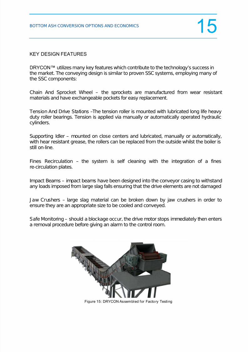
DRYCON™ utilizes many key features which contribute to the technology’s success inthe market. The conveying design is similar to proven SSC systems, employing many of the SSC components:
Chain And Sprocket Wheel – the sprockets are manufactured from wear resistantmaterials and have exchangeable pockets for easy replacement.
Tension And Drive Stations –The tension roller is mounted with lubricated long life heavyduty roller bearings. Tension is applied via manually or automatically operated hydraulic
cylinders.
Supporting Idler – mounted on close centers and lubricated, manually or automatically,with hear resistant grease, the rollers can be replaced from the outside whilst the boiler isstill on‐line.
Fines Recirculation – the system is self cleaning with the integration of a finesre‐circulation plates.
Impact Beams – impact beams have been designed into the conveyor casing to withstand
any loads imposed from large slag falls ensuring that the drive elements are not damaged
J aw Crushers – large slag material can be broken down by jaw crushers in order toensure they are an appropriate size to be cooled and conveyed.
Safe Monitoring – should a blockage occur, the drive motor stops immediately then entersa removal procedure before giving an alarm to the control room.
Figure 15: DRYCON Assembled for Facto ry Testing

8/22/2019 Bottom Ash Conversion Paper
http://slidepdf.com/reader/full/bottom-ash-conversion-paper 16/18
BOTTOM ASH CONVERSION OPTIONS AND ECONOMICS 16
BOTTOM ASH CONVERSION TECHNOLOGY SELECTION
To determine which of the Bottom Ash conversion technologies presented herein may bea consideration for your power plant, a detailed investigation of your facility will benecessary. The following summarizes the key impacts of the technologies.
BA CONVERSION SELECTION
COMPARISON
CONVENTIONAL TANK
FARM DEWATERING
REMOTE DEWATERING
CONVEYOR SYSTEM -
ASHCONTM
SUBMERGED
SCRAPER CONVEYOR
(SSC)DRYCON
TMSYSTEM
Physical LayoutNo Major Change
Required within the
boiler house
No Major Change
Required within the boiler
house
Removal of existing BA
Hopper and conveying
system with retrofit
under the boiler.
Removal of existing BA
Hopper and conveying
system with retrofit
under the boiler.
PC Appl icab le f or mos t unit s App lic able for most uni ts Appl icab le for mos t unit s App lic able f or most uni ts
CYCLONE Appl icab le for mos t unit s App lic able f or mos t u nit sNot Applicable (generally
due to space limitations)
Not Applicable (Boiler is
Wet Bottom)
Surface Impoundment Elimination Yes Yes Yes Yes
"Zero Discharge" (Water)Closed Loop System -
pH Conditioning
required
Closed Loop System - pH
Conditioning required
Closed Loop System - pH
Conditioning and Heat
Exchangers may be
required
Not required - No water is
used in the System
0&M Cost Impact~25 to 30 % Increase
with the addition of the
Tank Farm Dewatering
~5 to 10 % Increase with
the addition of the
ASHCON
~30-35% Decrease with
SSC
~40-50% Decrease with
DRYCON
Energy Consumption~80 to 90 % Increase
with the addition of the
Tank Farm Dewatering
~15 to 20 % Increase with
the addition of the
ASHCON
~45-55% Decrease with
SSC
~60-70% Decrease with
DRYCON
Boiler Efficiency No Change No Change No Change0.02% TO 0.07% Boi ler
Efficiency Increase
Energy Efficiency Considerations:
Boiler design type
Site Specific Limitations:
Environmental Considerations:
Maintenance Budget Considerations:
Figure 16: Bottom Ash Technologies Comparison

8/22/2019 Bottom Ash Conversion Paper
http://slidepdf.com/reader/full/bottom-ash-conversion-paper 17/18
BOTTOM ASH CONVERSION OPTIONS AND ECONOMICS 17
ECONOMIC COMPARISON:
Following is an estimated financial comparison of the technologies over a ten year periodof operation. A typical 500 MW Unit, with a current Surface Impoundment operation wasconsidered for this analysis.
Items included in this analysis are:
Ten Year Capital Cost Amortization (“Turnkey Project”)
Operation and Maintenance Costs
Electric Power Costs
Boiler Efficiency Improvement (Fuel Savings)
Costs are based upon single unit conversion
(For multiple unit conversions, ASHCON™ may exhibit some Capital cost benefits if multiple unitscan be discharged to single ASHCON™ system.)
TYPICAL 500 MW BOTTOM ASH CONVERSION COMPARISON
$0
$250,000
$500,000
$750,000
$1,000,000
$1,250,000
$1,500,000
$1,750,000
$2,000,000
$2,250,000
$2,500,000
$2,750,000
$3,000,000
$3,250,000
$3,500,000
$3,750,000
$4,000,000
$4,250,000
1 2 3 4 5 6 7 8 9 10
YEAR
A N N U A L
E Q U I V A L E N T
C O S T
I N C L U D I N G
T E N Y
E A R C
A P I T A L
C O S T
A M O R T I Z A T I O N
CONVENTIONAL ASHCON SSC DRYCON
Figure 17: Bottom Ash Technologies Economic Comparison

8/22/2019 Bottom Ash Conversion Paper
http://slidepdf.com/reader/full/bottom-ash-conversion-paper 18/18
BOTTOM ASH CONVERSION OPTIONS AND ECONOMICS 18
CONCLUSION
This paper has presented four viable alternatives to the disposal of bottom ash in ashponds. No one technology will apply to all plant sites and each of the four will be chosenby some plants facing the daunting task of closing their ash pond.
Two of the choices offered involve replacing the existing water impounded ash hoppersunder the existing boilers. While both of these continuous removal options would be theprimary choices under new boilers, they may not fit or apply to all retrofit situations.Hence the other two choices offered provide methods for diverting ash slurry away fromash pond disposal with little or no impact on the operating plant’s boiler island.
REFERENCES
1. Fleming, C.H. and Mooney, G.D., "Bottom Ash Conversion Options and Economics"Power-Gen International Conference, Orlando, FL, December 14-16, 2010
2. Fleming, C.H. and Mooney, G.D., "Bottom Ash Conversion Options and Economics"Electric Power Conference, Chicago, IL, May 10-12, 2011