boss br-1600cd owners manual
DESCRIPTION
Boss BR-1600CD Owners ManualTRANSCRIPT
Owner’s Manual
03343912 ’05-12-6N
Thank you, and congratulations on your choice of the BOSS BR-1600CD Digital Recording Studio.
Before using this unit, carefully read the sections entitled: “USING THE UNIT SAFELY” and “IMPORTANT NOTES” (Owner’s manual p. 2–3; p. 4–5). These sections provide important information concerning the proper operation of the unit. Additionally, in order to feel assured that you have gained a good grasp of every feature provided by your new unit, Basic Operation and Owner’s manual should be read in its entirety.
The manuals should be saved and kept on hand as a convenient reference.
How to use this manual
The BR-1600CD Owner’s manual consists of two volumes “
Basic Operation
” and “
Owner’s Manual
.”
“
Basic Operation
” explains the sequence of turning on this unit, recording, playback, mixing down and making an original Audio CD. To use the BR-1600CD, please read this book first.
“
Owner’s Manual
” covers the functions which are not mentioned in “Basic Operation.” Please read it for finer settings and more sophisticated use of the BR-1600CD.
Printing conventions in this manual
• Text or numerals enclosed in square brackets [ ] indicate buttons.
[PLAY]
PLAY button
[CURSOR]
CURSOR button
• Reference such as (p. **) indicate pages in this manual to which you can refer.
Copyright © 2003 BOSS CORPORATION
All rights reserved. No part of this publication may be reproduced in any form without the written permission of BOSS CORPORATION.
Section 2
Usin
gEffects
Section 3
Using
Rhythm
Section 4
Using the
CD-R/RW
Drive
Section 5
Usin
gM
IDI
Section 6
Usin
gU
SB
Section 7
Oth
er Conven
ient
Functio
ns
Appen
dices
Section 1
Adva
nced
Use
This product complies with the requirements of European Directive 89/336/EEC.
For EU Countries
For Canada
This Class B digital apparatus meets all requirements of the Canadian Interference-Causing Equipment Regulations.
Cet appareil numérique de la classe B respecte toutes les exigences du Règlement sur le matériel brouilleur du Canada.
NOTICE
AVIS
For the USA
FEDERAL COMMUNICATIONS COMMISSIONRADIO FREQUENCY INTERFERENCE STATEMENT
This equipment has been tested and found to comply with the limits for a Class B digital device, pursuant to Part 15 of the FCC Rules. These limits are designed to provide reasonable protection against harmful interference in a residential installation. This equipment generates, uses, and can radiate radio frequency energy and, if not installed and used in accordance with the instructions, may cause harmful interference to radio communications. However, there is no guarantee that interference will not occur in a particular installation. If this equipment does cause harmful interference to radio or television reception, which can be determined by turning the equipment off and on, the user is encouraged to try to correct the interference by one or more of the following measures:
– Reorient or relocate the receiving antenna.– Increase the separation between the equipment and receiver.– Connect the equipment into an outlet on a circuit different from that to which the receiver is connected.– Consult the dealer or an experienced radio/TV technician for help.
This device complies with Part 15 of the FCC Rules. Operation is subject to the following two conditions: (1) This device may not cause harmful interference, and (2) This device must accept any interference received, including interference that may cause undesired operation.
Unauthorized changes or modification to this system can void the users authority to operate this equipment.This equipment requires shielded interface cables in order to meet FCC class B Limit.
IMPORTANT: THE WIRES IN THIS MAINS LEAD ARE COLOURED IN ACCORDANCE WITH THE FOLLOWING CODE.
BLUE: BROWN:
As the colours of the wires in the mains lead of this apparatus may not correspond with the coloured markings identifying the terminals in your plug, proceed as follows:The wire which is coloured BLUE must be connected to the terminal which is marked with the letter N or coloured BLACK.The wire which is coloured BROWN must be connected to the terminal which is marked with the letter L or coloured RED.Under no circumstances must either of the above wires be connected to the earth terminal of a three pin plug.
NEUTRALLIVE
For the U.K.
2
USING THE UNIT SAFELY
001
• Before using this unit, make sure to read the instructions below, and the Owner’s Manual.
...........................................................................................................
002c
• Do not open (or modify in any way) the unit or its AC adaptor.
...........................................................................................................
003
• Do not attempt to repair the unit, or replace parts within it (except when this manual provides specific instructions directing you to do so). Refer all servicing to your retailer, the nearest Roland Service Center, or an authorized Roland distributor, as listed on the “Information” page.
...........................................................................................................
004
• Never use or store the unit in places that are:
• Subject to temperature extremes (e.g., direct sunlight in an enclosed vehicle, near a heating duct, on top of heat-generating equipment); or are
• Damp (e.g., baths, washrooms, on wet floors); or are
• Humid; or are
• Exposed to rain; or are
• Dusty; or are
• Subject to high levels of vibration............................................................................................................
007
• Make sure you always have the unit placed so it is level and sure to remain stable. Never place it on stands that could wobble, or on inclined surfaces.
...........................................................................................................
008c
• Be sure to use only the AC adaptor supplied with the unit. Also, make sure the line voltage at the installation matches the input voltage specified on the AC adaptor’s body. Other AC adaptors may use a different polarity, or be designed for a different voltage, so their use could result in damage, malfunction, or electric shock.
..........................................................................................................
008e
• Use only the attached power-supply cord. Also, the supplied power cord must not be used with any other device.
..........................................................................................................
009
• Do not excessively twist or bend the power cord, nor place heavy objects on it. Doing so can damage the cord, producing severed elements and short circuits. Damaged cords are fire and shock hazards!
..........................................................................................................
010
• This unit, either alone or in combination with an amplifier and headphones or speakers, may be capable of producing sound levels that could cause permanent hearing loss. Do not operate for a long period of time at a high volume level, or at a level that is uncomfortable. If you experience any hearing loss or ringing in the ears, you should immediately stop using the unit, and consult an audiologist.
..........................................................................................................
011
• Do not allow any objects (e.g., flammable material, coins, pins); or liquids of any kind (water, soft drinks, etc.) to penetrate the unit.
..........................................................................................................
Used for instructions intended to alert the user to the risk of injury or material damage should the unit be used improperly.
* Material damage refers to damage or other adverse effects caused with respect to the home and all its furnishings, as well to domestic animals or pets.
Used for instructions intended to alert the user to the risk of death or severe injury should the unit be used improperly.
The symbol alerts the user to things that must be carried out. The specific thing that must be done is indicated by the design contained within the circle. In the case of the symbol at left, it means that the power-cord plug must be unplugged from the outlet.
The symbol alerts the user to important instructions or warnings.The specific meaning of the symbol is determined by the design contained within the triangle. In the case of the symbol at left, it is used for general cautions, warnings, or alerts to danger.
The symbol alerts the user to items that must never be carried out (are forbidden). The specific thing that must not be done is indicated by the design contained within the circle. In the case of the symbol at left, it means that the unit must never be disassembled.
3
012b
• Immediately turn the power off, remove the AC adaptor from the outlet, and request servicing by your retailer, the nearest Roland Service Center, or an authorized Roland distributor, as listed on the “Information” page when:
• The AC adaptor, the power-supply cord, or the plug has been damaged; or
• If smoke or unusual odor occurs
• Objects have fallen into, or liquid has been spilled onto the unit; or
• The unit has been exposed to rain (or otherwise has become wet); or
• The unit does not appear to operate normally or exhibits a marked change in performance.
..........................................................................................................
013
• In households with small children, an adult should provide supervision until the child is capable of following all the rules essential for the safe operation of the unit.
..........................................................................................................
014
• Protect the unit from strong impact. (Do not drop it!)
..........................................................................................................
015
• Do not force the unit’s power-supply cord to share an outlet with an unreasonable number of other devices. Be especially careful when using extension cords—the total power used by all devices you have connected to the extension cord’s outlet must never exceed the power rating (watts/amperes) for the extension cord. Excessive loads can cause the insulation on the cord to heat up and eventually melt through.
..........................................................................................................
016
• Before using the unit in a foreign country, consult with your retailer, the nearest Roland Service Center, or an authorized Roland distributor, as listed on the “Information” sheet.
..........................................................................................................
023
• DO NOT play a CD-ROM disc on a conventional audio CD player. The resulting sound may be of a level that could cause permanent hearing loss. Damage to speakers or other system components may result.
..........................................................................................................
101b
• The unit and the AC adaptor should be located so their location or position does not interfere with their proper ventilation.
..........................................................................................................
102c
• Always grasp only the plug on the AC adaptor cord when plugging into, or unplugging from, an outlet or this unit.
..........................................................................................................
103b
• At regular intervals, you should unplug the AC adaptor and clean it by using a dry cloth to wipe all dust and other accumulations away from its prongs. Also, disconnect the power plug from the power outlet whenever the unit is to remain unused for an extended period of time. Any accumulation of dust between the power plug and the power outlet can result in poor insulation and lead to fire.
..........................................................................................................
104
• Try to prevent cords and cables from becoming entangled. Also, all cords and cables should be placed so they are out of the reach of children.
..........................................................................................................
106
• Never climb on top of, nor place heavy objects on the unit.
..........................................................................................................
107c
• Never handle the AC adaptor or its plugs with wet hands when plugging into, or unplugging from, an outlet or this unit.
..........................................................................................................
108b
• Before moving the unit, disconnect the AC adaptor and all cords coming from external devices.
..........................................................................................................
109b
• Before cleaning the unit, turn off the power and unplug the AC adaptor from the outlet.
..........................................................................................................
110b
• Whenever you suspect the possibility of lightning in your area, disconnect the AC adaptor from the outlet.
..........................................................................................................
118
• Should you remove the ground terminal, make sure to put it in a safe place out of children's reach, so there is no chance of it being swallowed accidentally.
..........................................................................................................
120
• Always turn the phantom power off when connecting any device other than condenser microphones that require phantom power. You risk causing damage if you mistakenly supply phantom power to dynamic microphones, audio playback devices, or other devices that don't require such power. Be sure to check the specifica-tions of any microphone you intend to use by referring to the manual that came with it.
(This instrument’s phantom power: +48 V DC, 7 mA Max)
..........................................................................................................
IMPORTANT NOTES
291a
In addition to the items listed under “USING THE UNIT SAFELY” on page 2–3, please read and observe the following:
Power Supply301• Do not connect this unit to same electrical outlet that is
being used by an electrical appliance that is controlled by an inverter (such as a refrigerator, washing machine, microwave oven, or air conditioner), or that contains a motor. Depending on the way in which the electrical appliance is used, power supply noise may cause this unit to malfunction or may produce audible noise. If it is not practical to use a separate electrical outlet, connect a power supply noise filter between this unit and the electrical outlet.
302• The AC adaptor will begin to generate heat after long
hours of consecutive use. This is normal, and is not a cause for concern.
307• Before connecting this unit to other devices, turn off the
power to all units. This will help prevent malfunctions and/or damage to speakers or other devices.
Placement351• Using the unit near power amplifiers (or other equipment
containing large power transformers) may induce hum. To alleviate the problem, change the orientation of this unit; or move it farther away from the source of interference.
352a• This device may interfere with radio and television
reception. Do not use this device in the vicinity of such receivers.
352b• Noise may be produced if wireless communications
devices, such as cell phones, are operated in the vicinity of this unit. Such noise could occur when receiving or initi-ating a call, or while conversing. Should you experience such problems, you should relocate such wireless devices so they are at a greater distance from this unit, or switch them off.
353• Observe the following when using the unit’s floppy disk
drive. For further details, refer to “Before Using CD-R/RW Discs” (p. 7).
• Do not place the unit near devices that produce a strong magnetic field (e.g., loudspeakers).
• Install the unit on a solid, level surface.
• Do not move the unit or subject it to vibration while the drive is operating.
354a• Do not expose the unit to direct sunlight, place it near
devices that radiate heat, leave it inside an enclosed vehicle, or otherwise subject it to temperature extremes. Excessive heat can deform or discolor the unit.
355b• When moved from one location to another where the
temperature and/or humidity is very different, water droplets (condensation) may form inside the unit. Damage or malfunction may result if you attempt to use the unit in this condition. Therefore, before using the unit, you must allow it to stand for several hours, until the condensation has completely evaporated.
Maintenance401a• For everyday cleaning wipe the unit with a soft, dry cloth
or one that has been slightly dampened with water. To remove stubborn dirt, use a cloth impregnated with a mild, non-abrasive detergent. Afterwards, be sure to wipe the unit thoroughly with a soft, dry cloth.
402• Never use benzine, thinners, alcohol or solvents of any
kind, to avoid the possibility of discoloration and/or deformation.
Repairs and Data452• Please be aware that all data contained in the unit’s
memory may be lost when the unit is sent for repairs. Important data should always be backed up on a storage device (e.g., CD-R/RW disk or external computer connected via USB), or written down on paper (when possible). During repairs, due care is taken to avoid the loss of data. However, in certain cases (such as when circuitry related to memory itself is out of order), we regret that it may not be possible to restore the data, and Roland assumes no liability concerning such loss of data.
Additional Precautions551• Please be aware that the contents of memory can be
irretrievably lost as a result of a malfunction, or the improper operation of the unit. To protect yourself against the risk of loosing important data, we recommend that you periodically save a backup copy of important data you have stored in the unit’s memory on a storage device (e.g., CD-R/RW disk or external computer connected via USB).
552• Unfortunately, it may be impossible to restore the contents
of data that was stored hard disk once it has been lost. Roland Corporation assumes no liability concerning such loss of data.
553• Use a reasonable amount of care when using the unit’s
buttons, sliders, or other controls; and when using its jacks and connectors. Rough handling can lead to malfunctions.
554• Never strike or apply strong pressure to the display.556• When connecting / disconnecting all cables, grasp the
connector itself—never pull on the cable. This way you will avoid causing shorts, or damage to the cable’s internal elements.
558a• To avoid disturbing your neighbors, try to keep the unit’s
volume at reasonable levels. You may prefer to use headphones, so you do not need to be concerned about those around you (especially when it is late at night).
559a• When you need to transport the unit, package it in the box
(including padding) that it came in, if possible. Otherwise, you will need to use equivalent packaging materials.
4
IMPORTANT NOTES
561• Use only the specified expression pedal (EV-5, FV-500L, or
FV-500H; sold separately). By connecting any other expression pedals, you risk causing malfunction and/or damage to the unit.
562• Use a cable from Roland to make the connection. If using
some other make of connection cable, please note the following precautions.
• Some connection cables contain resistors. Do not use cables that incorporate resistors for connecting to this unit. The use of such cables can cause the sound level to be extremely low, or impossible to hear. For infor-mation on cable specifications, contact the manufac-turer of the cable.
982• No data for the music that is played will be output from
MIDI OUT.
Handling CD-ROMs801• Avoid touching or scratching the shiny underside
(encoded surface) of the disc. Damaged or dirty CD-ROM discs may not be read properly. Keep your discs clean using a commercially available CD cleaner.
Copyright851• Unauthorized recording, distribution, sale, lending, public
performance, broadcasting, or the like, in whole or in part, of a work (musical composition, video, broadcast, public performance, or the like) whose copyright is held by a third party is prohibited by law.
852a• When exchanging audio signals through a digital
connection with an external instrument, this unit can perform recording without being subject to the restrictions of the Serial Copy Management System (SCMS). This is because the unit is intended solely for musical production, and is designed not to be subject to restrictions as long as it is used to record works (such as your own composi-tions) that do not infringe on the copyrights of others. (SCMS is a feature that prohibits second-generation and later copying through a digital connection. It is built into MD recorders and other consumer digital-audio equipment as a copyright-protection feature.)
853• Do not use this unit for purposes that could infringe on a
copyright held by a third party. We assume no responsi-bility whatsoever with regard to any infringements of third-party copyrights arising through your use of this unit.
About the License Agreement• The BR-1600CD and its CD-R/RW capability are designed
to allow you to reproduce material to which you have copyright, or material which the copyright owner has granted you permission to copy. Accordingly, repro-duction of Music CD or other copyrighted material without permission of the copyright owner avoiding technical prohibiting features of second-generation and later copying like SCMS or others constitutes copyright infringement and may incur penalties even in case such reproduction is for your own personal use and enjoyment (private use). Consult a copyright specialist or special publications for more detailed information on obtaining such permission from copyright holders.
Disclaimer of liability• BOSS/Roland will take no responsibility for any “direct
damages,” “consequential damages,” or “any other damages” which may result from your use of the BR-1600CD. These damages may include but are not limited to the following events which can occur when using the BR-1600CD.
• Any loss of profit that may occur to you
• Permanent loss of your music or data
• Inability to continue using the BR-1600CD itself or a connected device
204
...........................................................................................................
204* Microsoft and Windows are registered trademarks of
Microsoft Corporation.206e* The screen shots in this document are used in compliance
with the guidelines of the Microsoft Corporation.206j* Windows® is known officially as: “Microsoft®
Windows® operating system.”207* Apple and Macintosh are registered trademark of Apple
Computer, Inc.209* MacOS is a trademark of Apple Computer, Inc.220* All product names mentioned in this document are trade-
marks or registered trademarks of their respective owners.
...........................................................................................................
The explanations in this manual include illustrations that depict what should typically be shown by the display. Note, however, that your unit may incor-porate a newer, enhanced version of the system (e.g., includes newer sounds), so what you actually see in the display may not always match what appears in the manual.
5
6
Precautions Regarding the Hard Disk
The BR-1600CD contains an internal hard disk. This device is of an extremely high-precision design, and it can be easily damaged if not used and handled correctly. To ensure that the hard disk is being handled properly, you must adhere to the following:
Important Performance and Image DataOnce a hard disk fails to function normally, all data that has been stored on it could be destroyed.
All hard disks eventually wear out. Individual differences among hard disks and the conditions under which they are used have a considerable effect on a hard disk's lifespan. Some devices can be used continuously for many years, while in rare cases, others break down after a period of several months. We recommend that you consider the hard disk not as a permanent storage site, but as a place to store data temporarily. We also recommend that you back up important performance and image data onto the external media that is supported by your device.
For instructions on how to make such backups, refer to “Storing of songs and other hard-disk data to CD-R/RW discs (Backup)” (p. 204).
Note that Roland assumes no liability whatsoever, including monetary compensation, for the loss of any recorded content in the event of the malfunction of, or physical damage to the hard disk, or for any direct or incidental damages resulting from the loss of such data.
Precautions Regarding Setup and UseCertain hard disk setup procedures and usage conditions may result in the corruption of recorded data, malfunctioning, or physical damage to the disk, so be sure to observe the following precautions.
Do not subject the hard disk to vibration or shock, especially while the unit is in operation. Failure to observe this precaution can result in the hard disk being permanently damaged.
Conditions to be avoided:
• Lifting or moving the BR-1600CD while the power is turned on.• Transporting the BR-1600CD unprotected in an automobile trunk.• Knocking the BR-1600CD against table edges when it is being moved.• Positioning the BR-1600CD close to drums during performances.• Positioning the BR-1600CD close to amplifiers for guitars and other musical instruments during performances.
Do not set up the unit in any location where it may be affected by vibration from external sources, or on any surface that is not stable and level.
If the device includes a cooling fan, ensure that the fan and the side panel air vents remain unobstructed.
Do not block the ventilation holes provided in the case as this can result in the temperature inside the BR-1600CD rising, and this will drastically reduce the hard disk's lifespan.
Do not use the unit in conditions of high temperature and humidity or in any location subject to rapid temperature changes.
Do not unplug the power cord or switch off any circuit breakers in the circuit to which the unit is connected while the power is turned on.
Do not move the unit while the power is turned on or immediately after turning off the power. When transporting the unit, first turn off the power and confirm that the display screen has gone off, disconnect the power plug, then wait at least two minutes before moving the device.
When you need to transport the unit, package it in the box (including padding) that it came in, if possible. Otherwise, you will need to use equivalent packaging materials.
Emergency Procedures* The following procedures are to be used as emergency measures only, and are not recommended for normal operation.
If the device fails to respond to operational commands or does not complete operations, turn off the power. If the power does not shut off following normal shutdown procedures (Basic Operation; p. 9), disconnect the power plug.
If the unit does not operate normally when the power is turned on again, it may mean that the hard disk has been damaged. In such instances, consult your dealer or the nearest Roland Service Center. Note, however, that it may not be possible to recover any data from the hard disk once it has been lost.
In addition, even if the hard disk appears to be operating correctly, carry out a Surface Scan (p. 270) to confirm that it has not been damaged.
Before Using CD-R/RW Discs
Two different types of recordable disc can be used with the BR-1600CD—namely, CD-R discs and CD-RW discs.
What is a CD-R disc?CD-R (Compact Disc Recordable) is a CD to which data can be written. It is not possible to erase or move the data that has been written.
This type of disc should be used to create audio CDs that will be played on standard CD players. Playback of CD-RW discs will not be possible on this type of equipment. In addition, even if you have created an audio CD using a CD-R disc, playback will only be possible on players that support the playback of recordable discs.
What is a CD-RW disc?CD-RW (Compact Disc ReWritable) is a CD that can be written and erased. As a result, this type of recordable disc can be used again and again.
While you can create audio CDs using CD-RW discs, it will not be possible to play these CDs on a standard CD player. (You will, however, be able to play these discs using the BR-1600CD's CD-R/RW drive.)
Handling the CD-R/RW Disc Drive Before being shipped, a cardboard insert was placed in
the disk drive to protect it from vibration during transport. When you turn on the unit, press the EJECT button to remove this material before you use the CD-R/RW drive. This material should be saved, and reinserted whenever the unit is transported.
Install the unit on a solid, level surface in an area free from vibration. If the unit must be installed at an angle, be sure the installation does not exceed the permissible range.
Avoid using the unit immediately after it has been moved to a location with a level of humidity that is greatly different than its former location. Rapid changes in the environment can cause condensation to form inside the drive, which will adversely affect the operation of the drive and/or damage CD-R/RW discs. When the unit has been moved, allow it to become accustomed to the new environment (allow a few hours) before operating it.
Avoid using the CD-R/RW drive in locations with high temperatures. Failure to observe this precaution can result in the drive becoming unable to operate correctly or in write errors. In addition, this type of environment can also reduce the lifespan of the CD-R/RW drive.
Remove any disk from the drive before powering up or down.
To avoid the risk of malfunction and/or damage, insert only CD-R/RW discs into the disc drive. Never insert any other type of disc. Avoid getting paper clips, coins, or any other foreign objects inside the drive.
Do not touch the lens.
When the lens is dirty, clean the lens with a commercial lens blower.
If a write error occurs, carry out cleaning using a commercially available CD-RW drive lens cleaner.
* Note that some commercially available cleaners are intended
for CD-R drives, while others are intended for CD-RW drives.
Be sure to select a cleaner for CD-RW drives.
* Never use commercially available cleaner intended for
standard CD players. This type of cleaner cannot be used to
clean the BR-1600CD's write lens.
* Even if the recommended type of CD-R/RW disc is used in a
perfectly normal CD-R/RW drive, the possibility of write
errors cannot be completely eliminated. Please be aware that
this type of problem can still occur as a result of variations in
CD-R/RW drives and CD-R/RW disc manufacturing
differences.
Handling CD-R/RW Discs* In addition to the following precautions, please also read the
instructions provided with the CD-R/RW discs.
DO NOT play a CD-R/RW disc (CD-R/RW disc on which song data has been backed up) on a conventional audio CD player. The resulting sound may be of a level that could cause permanent hearing loss. Damage to speakers or other system components may result.
Upon handling the discs, please observe the following.
Do not touch the recorded surface of the disc.
Do not use in dusty areas.
Do not leave the disc in direct sunlight or an enclosed vehicle.
Keep the disc in the case.
7
Before Using CD-R/RW Discs
Compatibility of CD-R/RW discs and drives Ensure that the recommended type of CD-R/RW discs
are always used. Failure to observe this precaution can lead to an increase in the frequency of write errors.
Even when the recommended type of disc is used, there is still a possibility that write errors can occur. Please be aware that this type of problem can still result from variations in CD-R/RW drives and CD-R/RW disc manufacturing differences.
The usage of discs with printable labels is not recommended, even if these discs are of the recommended type. Certain storage conditions can cause discs with printable labels to warp, and write errors can occur as a result.
When you insert a CD-R/RW disc to built in CD-R/RW drive...When you insert a CD-R/RW disc to built in CD-R/RW drive, lock the CD-R/RW disc at correct position according to “Insert a CD-R/RW disc” below. Please be careful to lock a CD-R/RW disc correctly. Unless, it is possible that the disc tray is stuck and unable to remove a CD-R/RW disc.
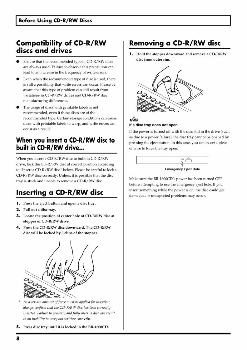
Inserting a CD-R/RW disc1. Press the eject button and open a disc tray.
2. Pull out a disc tray.
3. Locate the position of center hole of CD-R/RW disc at stopper of CD-R/RW drive.
4. Press the CD-R/RW disc downward. The CD-R/RW disc will be locked by 3 clips of the stopper.
fig.CD set
* As a certain amount of force must be applied for insertion,
always confirm that the CD-R/RW disc has been correctly
inserted. Failure to properly and fully insert a disc can result
in an inability to carry out writing correctly.
5. Press disc tray until it is locked in the BR-1600CD.
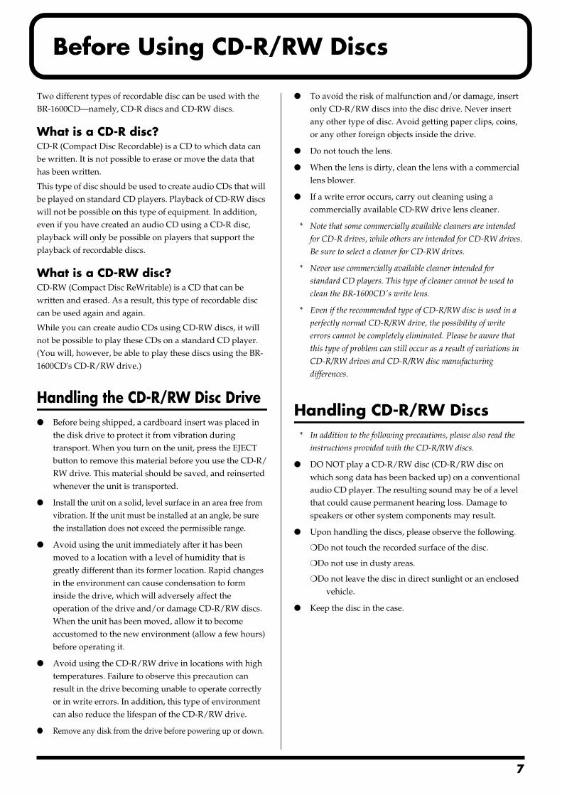
Removing a CD-R/RW disc1. Hold the stopper downward and remove a CD-R/RW
disc from outer rim.fig.CD eject
If a disc tray does not open
If the power is turned off with the disc still in the drive (such as due to a power failure), the disc tray cannot be opened by pressing the eject button. In this case, you can insert a piece of wire to force the tray open.fig.Hole
Make sure the BR-1600CD’s power has been turned OFF before attempting to use the emergency eject hole. If you insert something while the power is on, the disc could get damaged, or unexpected problems may occur.
Emergency Eject Hole
8
About the CD-ROM “Discrete Drums”
A CD-ROM is supplied with the BR-1600CD.
The CD-ROM includes a variety of drum phrases created by Discrete Drums.
These professionally recorded drum parts are saved as Loop Phrases that can easily be imported directly into the BR-1600CD and used in your songs.
Drum phrases are categorized and sorted under each folder in .WAV format files.
The BR-1600CD allows you to easily use these phrases by using the Loop Phrase Import function.
Since all the data included in this CD-ROM has already been factory-installed in the User bank of the Loop Phrase area of the BR-1600CD, you can easily use the Loop Phrase functions and add the audio to your tracks without using this CD-ROM.
However, in case you initialize your hard disk drive in the BR-1600CD, or accidentally erase the User Loop Phrases, you can recover all of the factory-installed Loop Phrases by importing them from this CD-ROM.
To import Loop Phrases from this CD-ROM, refer to “Create Loop Phrase” in “Section 3 Using Rhythm.” (“Using wave
data on a CD-ROM/R/RW disc (Loop Phrase Import)” (p. 180))
For more information about the factory-installed Loop Phrases in the User Bank, which are the original WAV files on this CD-ROM, please refer to “User Loop Phrase List” (separate sheet).
This CD-ROM is not an Audio CD. This CD-ROM should not be played with a consumer audio CD player. If it is, very loud
noises can be generated and audio equipment such as CD players, amplifiers or speakers can be damaged!!
9
1
Contents
USING THE UNIT SAFELY......................................................................2
IMPORTANT NOTES ...............................................................................4
Precautions Regarding the Hard Disk ..................................................6
Before Using CD-R/RW Discs ................................................................7
About the CD-ROM “Discrete Drums” ..................................................9
Introduction to the BR-1600CD............................................................22Main Features............................................................................................................................ 22
Panel Descriptions................................................................................24Control Surface......................................................................................................................... 24CD-R/RW drive .......................................................................................................................... 30Display ....................................................................................................................................... 31Rear Panel ................................................................................................................................. 32Front Panel ................................................................................................................................ 34
Extra information on jacks and connectors .......................................35Input jacks and connectors ..................................................................................................... 35
GUITAR/BASS jack...................................................................................................................... 35INPUT 1/MIC 1 jack..................................................................................................................... 35INPUT 2/MIC 2 jack..................................................................................................................... 35INPUT 3/MIC 3 jack through INPUT 8/MIC 8 jack ............................................................... 35DIGITAL IN connector................................................................................................................. 35
Output jacks and connectors .................................................................................................. 36LINE OUT jacks............................................................................................................................. 36DIGITAL OUT connector............................................................................................................. 36PHONES 1 and PHONES 2 jack ................................................................................................. 36
MIDI connectors........................................................................................................................ 36MIDI IN connector ........................................................................................................................ 36MIDI OUT connector .................................................................................................................... 36
USB connector.......................................................................................................................... 37Power supply ............................................................................................................................ 37
DC IN (AC adaptor) jack.............................................................................................................. 37
Common operations and display items..............................................38Top screen................................................................................................................................. 38Current position........................................................................................................................ 38FUNCTION buttons ([F1] through [F4])................................................................................... 38PAGE SCROLL buttons............................................................................................................ 39Scroll Bar................................................................................................................................... 39Cursor ........................................................................................................................................ 39TIME/VALUE dial....................................................................................................................... 40VALUE 1/PAN, VALUE 2, VALUE 3, and VALUE 4 knobs ..................................................... 40
0
Contents
Section 1 Advanced Use ...............41Re-recording only the portion that is mistaken (Punch In/Out) .......42
Manual punch in and punch out.............................................................................................. 42Performing manual punch in and punch out using [REC]..................................................... 42Performing manual punch in and punch out using a foot switch......................................... 43
Auto punch in and punch out.................................................................................................. 43Specifying the section to be re-recorded.................................................................................... 43Performing auto punch in and punch out................................................................................. 44
Repeating recording in a specific section (Loop Recording)............................................... 45Specifying the section to be repeated ......................................................................................... 45Specifying the section to be recorded......................................................................................... 45Performing loop recording .......................................................................................................... 45
Using V-Tracks......................................................................................46Switching V-Tracks................................................................................................................... 46Assigning names to V-Tracks (Track Name).......................................................................... 47Changing the V-Track to be written to an audio CD (the Final Mastering Track) ............... 47
Placing markers in your song (Marker) ..............................................48Basic marker operations.......................................................................................................... 48
Positioning a marker..................................................................................................................... 48Clearing markers........................................................................................................................... 48Moving to markers........................................................................................................................ 48
Editing markers......................................................................................................................... 49Moving markers ............................................................................................................................ 49Naming a marker .......................................................................................................................... 49Assigning an audio-CD song division to a marker.................................................................. 49Changing scenes assigned to markers ....................................................................................... 50Stopping automatically at a marker (Marker Stop) ................................................................. 50
Registering and recalling mixer settings (Scene)..............................51Registering, recalling, and deleting scenes........................................................................... 51Recalling a scene without changing track volumes.............................................................. 51
Recalling scenes automatically during recording or playback (Auto Scene)....52Setting an Auto Scene.............................................................................................................. 52Clearing an Auto Scene ........................................................................................................... 52Disabling Auto Scene............................................................................................................... 53Setting Auto Scene control of effects and track EQ ............................................................. 53
Finding the start or end of a section of audio (Scrub/Preview)........54Using Scrub to find the start of a section of audio ............................................................... 54Changing the scrubbing direction .......................................................................................... 55Using Scrub and Preview to find the end of a section of audio........................................... 55
Enabling Preview .......................................................................................................................... 55Using Scrub and Preview............................................................................................................. 55
11
Contents
Editing a recorded performance (Track Edit).....................................56Precautions when editing tracks............................................................................................. 56Copying audio data (Track Copy) ........................................................................................... 56Moving audio data (Track Move) ............................................................................................. 58Exchanging audio data (Track Exchange) ............................................................................. 60Inserting a blank space between audio data (Track Insert).................................................. 61Deleting audio data and closing the resulting gap (Track Cut)............................................ 62Erasing audio data (Track Erase)............................................................................................ 63
Maximizing the volume levels of data recorded to the tracks (Normalize) ............................................................................................65
Organizing your songs.........................................................................67Displaying song details (Song Information) .......................................................................... 67Copying songs (Song Copy) ................................................................................................... 68Erasing songs (Song Erase).................................................................................................... 69Making the most of hard disk capacity (Song Optimize) ...................................................... 70Protecting a song (Song Protect)............................................................................................ 71
Protecting a song (Song Protect) ................................................................................................. 71Removing song protection........................................................................................................... 71
Naming a song (Song Name)................................................................................................... 72Saving your song (Song Save)................................................................................................ 72
Section 2 Using Effects ..................73Makeup of BR-1600CD effects .............................................................74
Using insert effects...............................................................................76Effect patches and banks ........................................................................................................ 76Makeup of effect patches......................................................................................................... 77Modifying insert effect settings............................................................................................... 77
Changing the sound of insert effects using the VALUE knobs.............................................. 78Changing parameters assigned to VALUE knobs.................................................................... 78Changing effect block connections ............................................................................................. 79
Switching compressors, equalizers, and low-cut filters between stereo and mono ......... 80Saving insert effect settings (Effect Patch Write).................................................................. 81Copying insert effect settings (Effect Patch Copy) ............................................................... 82Changing insert effect connections........................................................................................ 82Using an expression pedal ...................................................................................................... 84
Insert effect algorithm list ....................................................................85BANK: GUITAR ......................................................................................................................... 85
1. COSM OD GUITAR AMP ....................................................................................................... 852. ACOUSTIC SIM ........................................................................................................................ 853. BASS SIM.................................................................................................................................... 854. COSM COMP GUITAR AMP.................................................................................................. 865. ACOUSTIC GUITAR................................................................................................................ 86
12
Contents
6. BASS MULTI.............................................................................................................................. 867. COSM BASS AMP..................................................................................................................... 868. COSM COMP BASS AMP........................................................................................................ 87
BANK: MIC................................................................................................................................. 879. VOCAL MULTI ......................................................................................................................... 8710. VOICE TRANSFORMER ....................................................................................................... 8711. COSM VOCAL COMP ........................................................................................................... 8712. MIC MODELING .................................................................................................................... 88
BANK: STEREO ........................................................................................................................ 8813. STEREO MULTI ...................................................................................................................... 8814. LO-FI BOX................................................................................................................................ 88
BANK: SIMUL ............................................................................................................................ 8815. VO+GT.AMP ........................................................................................................................... 8816. VO+AC.SIM............................................................................................................................. 8917. VO+ACOUSTIC ...................................................................................................................... 89
BANK: MULTI-CHANNEL ......................................................................................................... 8918. 8CH COMP EQ........................................................................................................................ 89
Insert effect parameter functions ........................................................90Acoustic Guitar Simulator ....................................................................................................... 90Acoustic Processor .................................................................................................................. 903 Band Equalizer....................................................................................................................... 914 Band Equalizer....................................................................................................................... 91Bass Simulator.......................................................................................................................... 92Bass Cut Filter .......................................................................................................................... 92Chorus ....................................................................................................................................... 922x2 Chorus ................................................................................................................................ 92Compressor............................................................................................................................... 93COSM Comp/Limiter (COSM Compressor/Limiter) ............................................................... 94COSM Overdrive/Distortion ..................................................................................................... 94COSM PreAmp&Speaker.......................................................................................................... 95De-esser..................................................................................................................................... 96Defretter..................................................................................................................................... 96Delay .......................................................................................................................................... 97Distance..................................................................................................................................... 97Doubling .................................................................................................................................... 97Enhancer ................................................................................................................................... 98Flanger....................................................................................................................................... 98Foot Volume .............................................................................................................................. 98Humanizer ................................................................................................................................. 98Limiter........................................................................................................................................ 99Low Cut Filter............................................................................................................................ 99Lo-Fi Box ................................................................................................................................... 99Mic Converter.......................................................................................................................... 100Noise Suppressor ................................................................................................................... 100Octave...................................................................................................................................... 100Pan ........................................................................................................................................... 101Phaser...................................................................................................................................... 101Pickup Simulator .................................................................................................................... 101
13
Contents
Pitch Shifter............................................................................................................................. 102Preamp..................................................................................................................................... 103Ring Modulator ....................................................................................................................... 104Short Delay.............................................................................................................................. 104Slow Gear ................................................................................................................................ 104Speaker Simulator .................................................................................................................. 104Sub Equalizer .......................................................................................................................... 105Tremolo.................................................................................................................................... 105Tremolo/Pan ............................................................................................................................ 105Uni-V ........................................................................................................................................ 105Vibrato ..................................................................................................................................... 106Voice Transformer .................................................................................................................. 106Wah .......................................................................................................................................... 106
Using track-specific compressors and equalizers ..........................108Compressors and equalizers................................................................................................. 108Compressor and equalizer connections .............................................................................. 108Adjusting the sound of compressors and equalizers ......................................................... 109
Adjusting a compressor ............................................................................................................. 109Selecting tracks to be compressed ............................................................................................ 110Switching compressors between stereo and mono (Stereo Link) ........................................ 110Adjusting a three-band equalizer ............................................................................................. 110Switching equalizers between stereo and mono (Stereo Link) ............................................ 111
Using loop effects...............................................................................112About loop effects .................................................................................................................. 112About loop effect connections .............................................................................................. 112Basic loop effect operations.................................................................................................. 113
Adjusting the sound of loop effects.......................................................................................... 113Adjusting reverb.......................................................................................................................... 113Adjusting chorus ......................................................................................................................... 114Adjusting delay ........................................................................................................................... 114Adjusting doubling..................................................................................................................... 115
Fixing the pitch of vocals/Adding a backing chorus to vocals (Vocal Tool Box) .....................116
The Vocal Tool Box ................................................................................................................ 116Makeup of the Vocal Tool Box............................................................................................... 116Vocal Tool Box patches ......................................................................................................... 117Fixing the pitch of vocals (Pitch Correction) ....................................................................... 117Setting the correction method for vocal pitch (Pitch Correction Edit) .............................. 118Applying a backing chorus to vocals (Harmony Sequence) .............................................. 119Inserting rests in a backing chorus ...................................................................................... 120Setting the application method for backing choruses (Harmony Sequence Edit) ........... 120Saving Vocal Tool Box settings (Patch Write) ..................................................................... 121Copying Vocal Tool Box settings (Patch Copy) .................................................................. 122
14
Contents
Recreating the characteristics of different monitor speakers (Speaker Modeling) ..............................123
Makeup of Speaker Modeling ................................................................................................ 123Connecting external monitor speakers ................................................................................ 123Speaker Modeling patches .................................................................................................... 124Using Speaker Modeling ........................................................................................................ 124
Turning off Speaker Modeling.................................................................................................. 124Modifying Speaker Modeling settings .................................................................................. 124Saving Speaker Modeling settings (Patch Write) ................................................................ 125Copying Speaker Modeling settings (Patch Copy).............................................................. 126
Speaker Modeling parameter functions............................................127SP Modeling (speaker modeling) .......................................................................................... 127Bass Cut Filter ........................................................................................................................ 128Low Freq Trimmer .................................................................................................................. 128High Freq Trimmer.................................................................................................................. 128Limiter...................................................................................................................................... 128
Using the Mastering Tool Kit .............................................................129The Mastering Tool Kit ........................................................................................................... 129Makeup of the Mastering Tool Kit ......................................................................................... 129Modifying Mastering Tool Kit settings (Edit) ....................................................................... 130Saving Mastering Tool Kit settings (Patch Write)................................................................ 131Copying Mastering Tool Kit settings (Patch Copy) ............................................................. 131Performing automatic fade-in and fade-out (Auto Fade In/Out)......................................... 132
Performing automatic fade-in (Auto Fade In) ........................................................................ 132Performing automatic fade-out (Auto Fade Out)................................................................... 133
Mastering Tool Kit parameter functions ...........................................134Equalizer.................................................................................................................................. 134Bass Cut Filter ........................................................................................................................ 135Enhancer ................................................................................................................................. 135Input ......................................................................................................................................... 135Expander ................................................................................................................................. 135Compressor............................................................................................................................. 136Mixer ........................................................................................................................................ 136Limiter...................................................................................................................................... 136Output ...................................................................................................................................... 136
Effect parameters assigned to VALUE knobs.................................137
15
Contents
Section 3 Using Rhythm..............145Makeup of Drum/Bass/Loop Phrase .................................................146
Drums ...................................................................................................................................... 146Bass ......................................................................................................................................... 146Loop Phrases .......................................................................................................................... 147
Rhythm arrangements........................................................................148Pattern mode and Arrangement mode ................................................................................. 148
Using drums ........................................................................................149Setting the track type ............................................................................................................. 149Playing drum sounds ............................................................................................................. 149Selecting a drum kit................................................................................................................ 150Selecting drum patterns......................................................................................................... 150Changing the drum pattern tempo........................................................................................ 151
Setting the tempo using [TAP].................................................................................................. 151
Creating drum patterns ......................................................................152Preparing for recording.......................................................................................................... 152Creating drum patterns using real-time recording.............................................................. 153
Practicing before recording (Rehearsal)................................................................................... 154Recording in perfect time (Quantize)....................................................................................... 154
Creating drum patterns using step recording ..................................................................... 155Correcting drum patterns (Microscope) ............................................................................... 157Changing the drum pattern’s groove (Swing)...................................................................... 159Changing a drum pattern’s name.......................................................................................... 160Copying drum patterns .......................................................................................................... 160Deleting drum patterns .......................................................................................................... 161Loading drum patterns from the CD-R/RW drive (SMF Import) ......................................... 161
Using bass...........................................................................................163Setting the track type ............................................................................................................. 163Playing bass............................................................................................................................ 163Selecting bass sounds........................................................................................................... 164Selecting bass patterns ......................................................................................................... 164Specifying bass pattern chords ............................................................................................ 165Changing the bass pattern’s tempo...................................................................................... 165
Creating bass patterns .......................................................................166Preparing for recording.......................................................................................................... 166Creating bass patterns using real-time recording............................................................... 167
Practicing before recording (Rehearsal)................................................................................... 168Recording in perfect time (Quantize)....................................................................................... 168
Creating bass patterns using step recording ...................................................................... 169Correcting bass patterns (Microscope)................................................................................ 170Changing the bass pattern’s groove (Swing) ...................................................................... 172Changing a bass pattern’s name .......................................................................................... 173
16
Contents
Copying bass patterns ........................................................................................................... 173Deleting bass patterns ........................................................................................................... 174Loading bass patterns from the CD-R/RW drive (SMF Import) .......................................... 174
Using Loop Phrases ...........................................................................176Setting the track type ............................................................................................................. 176Playing Loop Phrases ............................................................................................................ 176Selecting a Loop Phrase ........................................................................................................ 177Changing the Loop Phrase tempo ........................................................................................ 178
Setting the tempo using [TAP].................................................................................................. 178
Creating Loop Phrases.......................................................................179Using a portion of an audio track.......................................................................................... 179Using wave data on a CD-ROM/R/RW disc (Loop Phrase Import) ..................................... 180
Reading all files at once.............................................................................................................. 181Specifying and modifying the source loop phrase (Time Modify) ..................................... 182Modifying Loop Phrase settings ........................................................................................... 183Assigning Loop Phrases to track buttons ........................................................................... 184Copying Loop Phrases........................................................................................................... 184Erasing Loop Phrases............................................................................................................ 185
Setting the Universal Beat for Drums, Bass, and Loop Phrases ...186
Using rhythm arrangements ..............................................................187Selecting a rhythm arrangement........................................................................................... 187Changing the rhythm arrangement tempo ........................................................................... 187
Setting the tempo using [TAP].................................................................................................. 188
Creating rhythm arrangements .........................................................189Assembling drum and bass patterns.................................................................................... 189Canceling pattern allocations................................................................................................ 189Inserting patterns ................................................................................................................... 190Inputting chords ..................................................................................................................... 190Changing and moving chords ............................................................................................... 191Deleting chords....................................................................................................................... 191Inserting chords...................................................................................................................... 191Assembling Loop Phrases..................................................................................................... 192Canceling Loop Phrase allocations ...................................................................................... 193Inserting Loop Phrases.......................................................................................................... 193Copying a Loop Phrase from a rhythm arrangement to an audio track............................ 193Modifying all of the loop phrases in the current rhythm arrangement (Arrangement Modify)....... 195Naming and saving rhythm arrangements........................................................................... 196Copying a rhythm arrangement ............................................................................................ 196Deleting a rhythm arrangement............................................................................................. 197
Setting tempos and beats for individual measures (Tempo Map/Beat Map) ...198Setting tempos for individual measures (Tempo Map) ....................................................... 198Setting beats for individual measures (Beat Map) .............................................................. 199
17
Contents
Using a metronome ............................................................................200Setting the track type ............................................................................................................. 200Playing a metronome ............................................................................................................. 200Selecting metronome sounds ............................................................................................... 201Selecting outputs for the metronome................................................................................... 201
Section 4 Using the CD-R/RW Drive ..203Using the CD-R/RW drive to exchange data.....................................204
Storing of songs and other hard-disk data to CD-R/RW discs (Backup) .......................... 204Backing up a song (Song Backup) ............................................................................................ 204Backing up user data (User Backup) ........................................................................................ 205Backing up all data on the hard disk (HDD Backup) ............................................................ 206
Reading songs and other backup data back into the hard disk (Recover)....................... 207Reading backup songs back into the hard disk (Song Recover) .......................................... 207Reading backup user data back into the hard disk (User Recover)..................................... 208Reading backed-up hard disk contents back into the hard disk (HDD Recover) ............. 209
Copying and writing waveform data .................................................210Copying waveform data from a computer to the audio tracks (WAV/AIFF Import) .......... 210Copying audio track waveform data to computers (WAV/AIFF Export) ............................ 211Playing SMFs using external MIDI instruments (SMF Player) ............................................ 213Erasing data from a CD-RW disc........................................................................................... 214Setting the time until the CD-R/RW drive stops (CD Hold Time)........................................ 215
Convenient functions for audio CD creation....................................216Precautions ............................................................................................................................. 216Setting the time between songs (Pre-Gap) .......................................................................... 216Erasing CD-RW discs (CD-RW Erase) .................................................................................. 217Enabling playback on CD players (Finalize) ........................................................................ 218Importing songs from CDs to audio tracks (Audio CD Import) .......................................... 219
Section 5 Using MIDI...................221MIDI fundamentals ..............................................................................222
What is MIDI? .......................................................................................................................... 222MIDI connectors...................................................................................................................... 222MIDI channels.......................................................................................................................... 222MIDI Implementation Charts .................................................................................................. 222
Playing drum and bass patterns on external MIDI sound module ............223Drum sounds and note numbers .......................................................................................... 224
Synchronizing external MIDI sequencers and rhythm machines...225Synchronizing a MIDI device to the rhythm’s tempo using the MIDI timing clock........... 225
18
Contents
Synchronizing a MIDI sequencer to the playback time using MTC ................................... 226Changing the TIME field display.............................................................................................. 228
Synchronizing a MIDI device by recording its tempo changes on the BR-1600CD (Sync Track) .......... 228Setting the starting time of synchronization (Sync Offset) ................................................ 230
Controlling MMC-compatible devices from the BR-1600CD...........231
Controlling track volumes via MIDI (MIDI Fader) .............................232Turning MIDI Fader on and off............................................................................................... 232Setting the MIDI channel for MIDI Fader............................................................................... 233Confirming the current fader positions ................................................................................ 233
Inputting drum and bass patterns from a MIDI keyboard (MIDI Recording)............................................234
Using MIDI to Control the Switching of the Insert Effects (Effects Program Change) ...............................235
Controlling external video devices from the BR-1600CD (V-LINK) ...........236What is V-LINK?...................................................................................................................... 236What can V-LINK do? ............................................................................................................. 236Connecting V-LINK devices................................................................................................... 236Using V-LINK........................................................................................................................... 236Changing V-LINK function assignments .............................................................................. 237Recording and playing V-LINK control operations ............................................................. 238
Recording control operations .................................................................................................... 238Playing recorded control operations ........................................................................................ 238Erasing recorded control operations ........................................................................................ 238
Section 6 Using USB....................239Before Using USB (Overview)............................................................240
Operations that can be performed via USB ......................................................................... 240Compatible OS ........................................................................................................................ 240Connecting a computer.......................................................................................................... 241Structure of data on the BR-1600CD’s hard disk................................................................. 241
Backing up the BR-1600CD’s data ....................................................242With Windows ......................................................................................................................... 242With Macintosh ....................................................................................................................... 243
Reading backup data back into the BR-1600CD from the PC (Recover) ............................245
With Windows ......................................................................................................................... 245With Macintosh ....................................................................................................................... 246
19
Contents
Saving BR-1600CD track data in WAV/AIFF format (WAV/AIFF Export) ...........................................248
With Windows ......................................................................................................................... 248With Macintosh ....................................................................................................................... 250
Loading WAV/AIFF files in BR-1600CD tracks (WAV/AIFF Import)..........................................252
With Windows ......................................................................................................................... 252With Macintosh ....................................................................................................................... 253
Section 7 Other Convenient Functions.....255Tuning instruments (Tuner) ...............................................................256
Setting the reference pitch .................................................................................................... 256Tuning...................................................................................................................................... 256
Automatically adjusting the input volume balance (Level Calibration).....258Automatically adjusting the volume balance....................................................................... 258Restoring the original volume balance................................................................................. 258Manually adjusting the input volume balance ..................................................................... 259
Muting individual inputs.....................................................................260
Inputting audio with no loss of quality (Digital In Assign)..............261
Creating a master tape protected from digital copying ..................262
Changing the content of the level meter display (Pre/Post Fader) ...........263
Using condenser microphones (Phantom Power)...........................264
Mixing audio-device output with the BR-1600CD’s output (Audio Sub Mix) ................................266
Initializing all BR-1600CD settings (Initialize) ..................................267
Performing hard disk operations ......................................................269Viewing information about the hard disk (Hard Disk Information) .................................... 269Initializing the hard disk (Disk Initialize)............................................................................... 270Initializing only one of multiple partitions............................................................................ 271
20
Contents
Appendices ................................273Troubleshooting..................................................................................274
Error Messages ...................................................................................277
Operation of the INPUT SELECT buttons .........................................280Internal connection diagrams for each INPUT SELECT condition .................................... 281
When [GUITAR/BASS] is selected .......................................................................................... 281When [VOCAL] is selected ........................................................................................................ 282When [SIMUL] is selected.......................................................................................................... 282When [MULTI-TRACK] is selected.......................................................................................... 283When [STEREO TRACKS] is selected ...................................................................................... 284
REC MODE (Recording Mode) Operations .......................................285Internal connection diagrams for each recording mode .................................................... 286
When INPUT or BOUNCE is selected ..................................................................................... 286When MASTERING is selected................................................................................................. 287
MIDI Implementation...........................................................................288
Specifications......................................................................................295
Index.....................................................................................................297
21
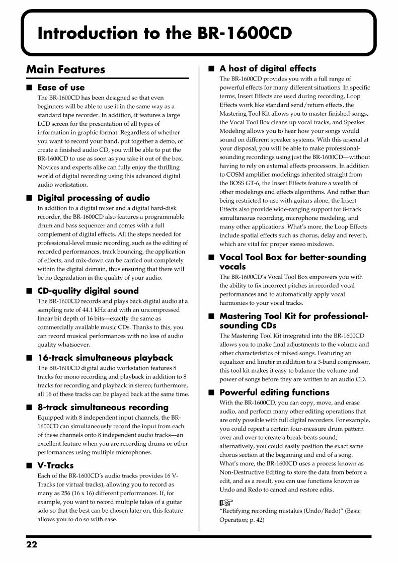
2
Introduction to the BR-1600CD
Main Features Ease of use
The BR-1600CD has been designed so that even beginners will be able to use it in the same way as a standard tape recorder. In addition, it features a large LCD screen for the presentation of all types of information in graphic format. Regardless of whether you want to record your band, put together a demo, or create a finished audio CD, you will be able to put the BR-1600CD to use as soon as you take it out of the box. Novices and experts alike can fully enjoy the thrilling world of digital recording using this advanced digital audio workstation.
Digital processing of audioIn addition to a digital mixer and a digital hard-disk recorder, the BR-1600CD also features a programmable drum and bass sequencer and comes with a full complement of digital effects. All the steps needed for professional-level music recording, such as the editing of recorded performances, track bouncing, the application of effects, and mix-down can be carried out completely within the digital domain, thus ensuring that there will be no degradation in the quality of your audio.
CD-quality digital soundThe BR-1600CD records and plays back digital audio at a sampling rate of 44.1 kHz and with an uncompressed linear bit depth of 16 bits—exactly the same as commercially available music CDs. Thanks to this, you can record musical performances with no loss of audio quality whatsoever.
16-track simultaneous playbackThe BR-1600CD digital audio workstation features 8 tracks for mono recording and playback in addition to 8 tracks for recording and playback in stereo; furthermore, all 16 of these tracks can be played back at the same time.
8-track simultaneous recordingEquipped with 8 independent input channels, the BR-1600CD can simultaneously record the input from each of these channels onto 8 independent audio tracks—an excellent feature when you are recording drums or other performances using multiple microphones.
V-TracksEach of the BR-1600CD’s audio tracks provides 16 V- Tracks (or virtual tracks), allowing you to record as many as 256 (16 x 16) different performances. If, for example, you want to record multiple takes of a guitar solo so that the best can be chosen later on, this feature allows you to do so with ease.
A host of digital effectsThe BR-1600CD provides you with a full range of powerful effects for many different situations. In specific terms, Insert Effects are used during recording, Loop Effects work like standard send/return effects, the Mastering Tool Kit allows you to master finished songs, the Vocal Tool Box cleans up vocal tracks, and Speaker Modeling allows you to hear how your songs would sound on different speaker systems. With this arsenal at your disposal, you will be able to make professional-sounding recordings using just the BR-1600CD—without having to rely on external effects processors. In addition to COSM amplifier modelings inherited straight from the BOSS GT-6, the Insert Effects feature a wealth of other modelings and effects algorithms. And rather than being restricted to use with guitars alone, the Insert Effects also provide wide-ranging support for 8-track simultaneous recording, microphone modeling, and many other applications. What’s more, the Loop Effects include spatial effects such as chorus, delay and reverb, which are vital for proper stereo mixdown.
Vocal Tool Box for better-sounding vocalsThe BR-1600CD’s Vocal Tool Box empowers you with the ability to fix incorrect pitches in recorded vocal performances and to automatically apply vocal harmonies to your vocal tracks.
Mastering Tool Kit for professional-sounding CDsThe Mastering Tool Kit integrated into the BR-1600CD allows you to make final adjustments to the volume and other characteristics of mixed songs. Featuring an equalizer and limiter in addition to a 3-band compressor, this tool kit makes it easy to balance the volume and power of songs before they are written to an audio CD.
Powerful editing functionsWith the BR-1600CD, you can copy, move, and erase audio, and perform many other editing operations that are only possible with full digital recorders. For example, you could repeat a certain four-measure drum pattern over and over to create a break-beats sound; alternatively, you could easily position the exact same chorus section at the beginning and end of a song. What’s more, the BR-1600CD uses a process known as Non-Destructive Editing to store the data from before a edit, and as a result, you can use functions known as Undo and Redo to cancel and restore edits.
“Rectifying recording mistakes (Undo/Redo)” (Basic Operation; p. 42)
2
Introduction to the BR-1600CD
Saving of mixer settingsThe term Scene is used to describe a batch of BR-1600CD mixer and effect settings, and up to 100 scenes can be set up and stored for each song. Accordingly, these settings can be conveniently recalled whenever you are balancing volumes during mix-down, comparing the sound of different effects, or performing other similar operations. In addition, another BR-1600CD function known as Auto Scene allows registered scenes to be recalled automatically during playback.
“Registering and recalling mixer settings (Scene)” (p. 51)
Rapid relocation of the current positionThe BR-1600CD’s Marker function allows you to position as many as 100 different markers at various points within your song. For example, if you position markers at the end of the intro, the beginning of the guitar solo, and other similar points, you will be able to jump to these points in an instant whenever you want to listen to the corresponding sections again. You can also assign names to any or all of these markers, and this proves extremely helpful during involved editing sessions.
“Placing markers in your song (Marker)” (p. 48)
PCM Drum/BassA PCM Drum/Bass (p. 146) capable of sequencing drum and bass patterns has been integrated into the BR-1600CD, and you will find this extremely useful whenever you need to put together songs based on phrases or other ideas that can come to you at any time. Once you have chosen the drum and bass patterns that best suit your idea, you can easily set the tempo to the right speed. What’s more, you can also combine different drum and bass patterns to create a rhythm-section performance with interesting variations at appropriate points during your song, and the PCM Drum/Bass also allows you to set up chord progressions for the bass part. Once you have played and recorded tracks along with the BR-1600CD’s PCM Drum/Bass, it will then be very easy to perform edits at measure positions.
“Section 3 Using Rhythm” (p. 145)
Loop phrase functionalityThe BR-1600CD lets you import commercially available loop phrase data using the CD- R/RW drive and then save this data on the internal hard disk. The tempo for these loop phrases can then be freely set to the required speed so that they can be played in sync with your recorded tracks. Using this function, you can easily create songs by layering performances over break beats or other rhythm patterns.
Creation of audio and backup CDsThe BR-1600CD comes with its own CD-R/RW drive already installed, and you can use this to easily create audio CDs by burning your finished songs onto CD-R discs. In addition, the CD-R/RW drive also allows you to use CD-R/RW discs to conveniently back up songs and song data.
Before you use the CD-R/RW drive, it is important that you first of all read “Before Using CD-R/RW Discs” (p. 7).
Chromatic tunerFeaturing a chromatic tuner covering the range from C1 to B6, the BR-1600CD allows you to quickly tune any guitar or bass guitar connected to it (p. 256).
Automatic level calibrationUsing a function called Level Calibration, the BR-1600CD Digital Recording Studio can detect and automatically balance the volumes of its various input (p. 258).
23
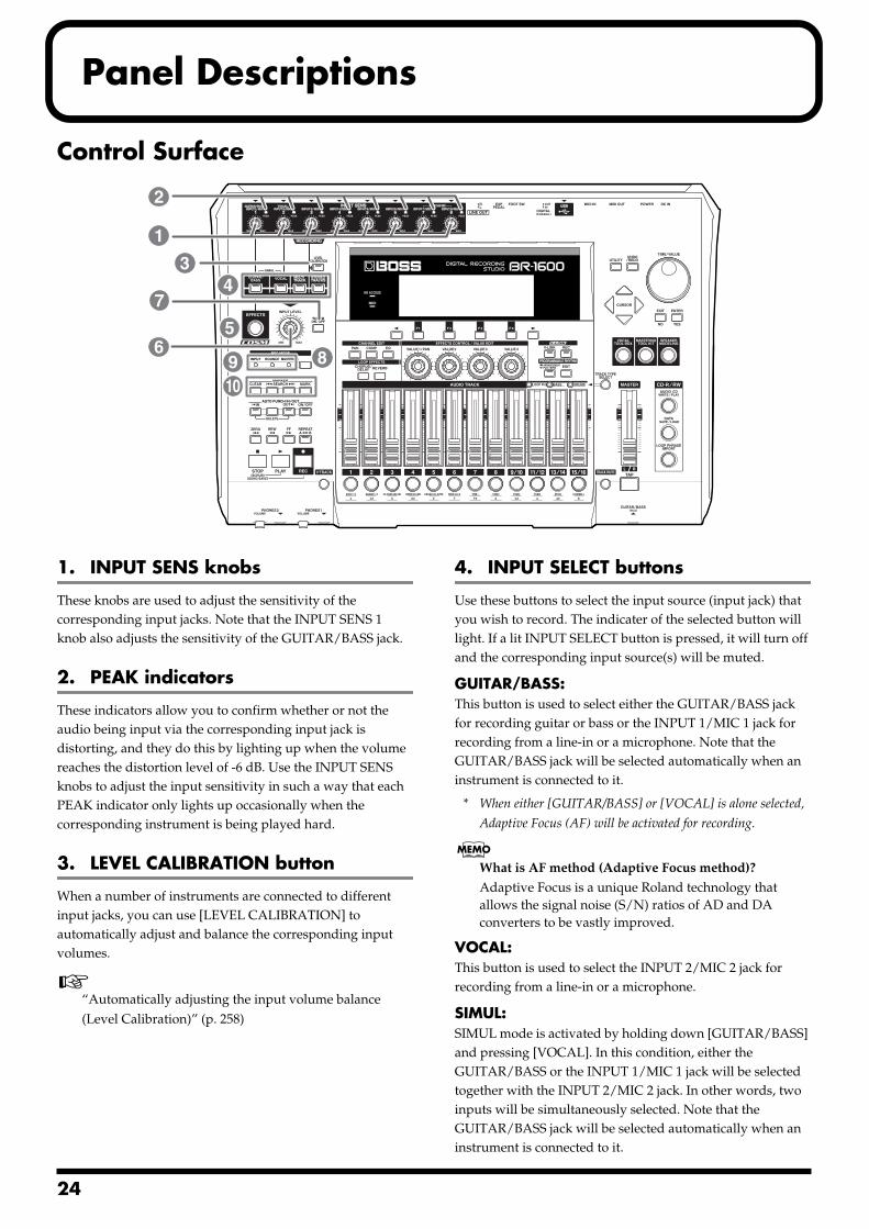
2
Panel Descriptions
Control Surfacefig.05-01a
1. INPUT SENS knobs
These knobs are used to adjust the sensitivity of the corresponding input jacks. Note that the INPUT SENS 1 knob also adjusts the sensitivity of the GUITAR/BASS jack.
2. PEAK indicators
These indicators allow you to confirm whether or not the audio being input via the corresponding input jack is distorting, and they do this by lighting up when the volume reaches the distortion level of -6 dB. Use the INPUT SENS knobs to adjust the input sensitivity in such a way that each PEAK indicator only lights up occasionally when the corresponding instrument is being played hard.
3. LEVEL CALIBRATION button
When a number of instruments are connected to different input jacks, you can use [LEVEL CALIBRATION] to automatically adjust and balance the corresponding input volumes.
“Automatically adjusting the input volume balance (Level Calibration)” (p. 258)
4. INPUT SELECT buttons
Use these buttons to select the input source (input jack) that you wish to record. The indicater of the selected button will light. If a lit INPUT SELECT button is pressed, it will turn off and the corresponding input source(s) will be muted.
GUITAR/BASS:This button is used to select either the GUITAR/BASS jack for recording guitar or bass or the INPUT 1/MIC 1 jack for recording from a line-in or a microphone. Note that the GUITAR/BASS jack will be selected automatically when an instrument is connected to it.
* When either [GUITAR/BASS] or [VOCAL] is alone selected,
Adaptive Focus (AF) will be activated for recording.
What is AF method (Adaptive Focus method)?
Adaptive Focus is a unique Roland technology that allows the signal noise (S/N) ratios of AD and DA converters to be vastly improved.
VOCAL:This button is used to select the INPUT 2/MIC 2 jack for recording from a line-in or a microphone.
SIMUL:SIMUL mode is activated by holding down [GUITAR/BASS] and pressing [VOCAL]. In this condition, either the GUITAR/BASS or the INPUT 1/MIC 1 jack will be selected together with the INPUT 2/MIC 2 jack. In other words, two inputs will be simultaneously selected. Note that the GUITAR/BASS jack will be selected automatically when an instrument is connected to it.
1
2
34
5
7
689
10
4
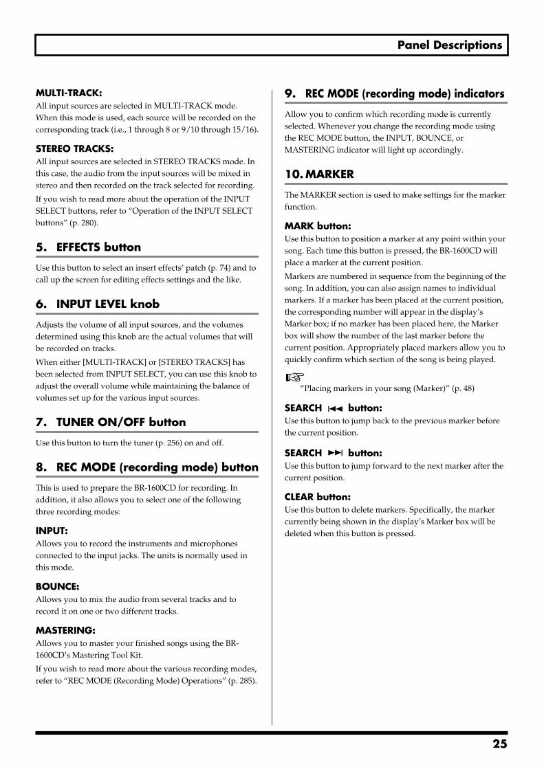
Panel Descriptions
MULTI-TRACK:All input sources are selected in MULTI-TRACK mode. When this mode is used, each source will be recorded on the corresponding track (i.e., 1 through 8 or 9/10 through 15/16).
STEREO TRACKS:All input sources are selected in STEREO TRACKS mode. In this case, the audio from the input sources will be mixed in stereo and then recorded on the track selected for recording.
If you wish to read more about the operation of the INPUT SELECT buttons, refer to “Operation of the INPUT SELECT buttons” (p. 280).
5. EFFECTS button
Use this button to select an insert effects’ patch (p. 74) and to call up the screen for editing effects settings and the like.
6. INPUT LEVEL knob
Adjusts the volume of all input sources, and the volumes determined using this knob are the actual volumes that will be recorded on tracks.
When either [MULTI-TRACK] or [STEREO TRACKS] has been selected from INPUT SELECT, you can use this knob to adjust the overall volume while maintaining the balance of volumes set up for the various input sources.
7. TUNER ON/OFF button
Use this button to turn the tuner (p. 256) on and off.
8. REC MODE (recording mode) button
This is used to prepare the BR-1600CD for recording. In addition, it also allows you to select one of the following three recording modes:
INPUT:Allows you to record the instruments and microphones connected to the input jacks. The units is normally used in this mode.
BOUNCE:Allows you to mix the audio from several tracks and to record it on one or two different tracks.
MASTERING:Allows you to master your finished songs using the BR-1600CD’s Mastering Tool Kit.
If you wish to read more about the various recording modes, refer to “REC MODE (Recording Mode) Operations” (p. 285).
9. REC MODE (recording mode) indicators
Allow you to confirm which recording mode is currently selected. Whenever you change the recording mode using the REC MODE button, the INPUT, BOUNCE, or MASTERING indicator will light up accordingly.
10. MARKER
The MARKER section is used to make settings for the marker function.
MARK button:Use this button to position a marker at any point within your song. Each time this button is pressed, the BR-1600CD will place a marker at the current position.
Markers are numbered in sequence from the beginning of the song. In addition, you can also assign names to individual markers. If a marker has been placed at the current position, the corresponding number will appear in the display’s Marker box; if no marker has been placed here, the Marker box will show the number of the last marker before the current position. Appropriately placed markers allow you to quickly confirm which section of the song is being played.
“Placing markers in your song (Marker)” (p. 48)
SEARCH button:Use this button to jump back to the previous marker before the current position.
SEARCH button:Use this button to jump forward to the next marker after the current position.
CLEAR button:Use this button to delete markers. Specifically, the marker currently being shown in the display’s Marker box will be deleted when this button is pressed.
25
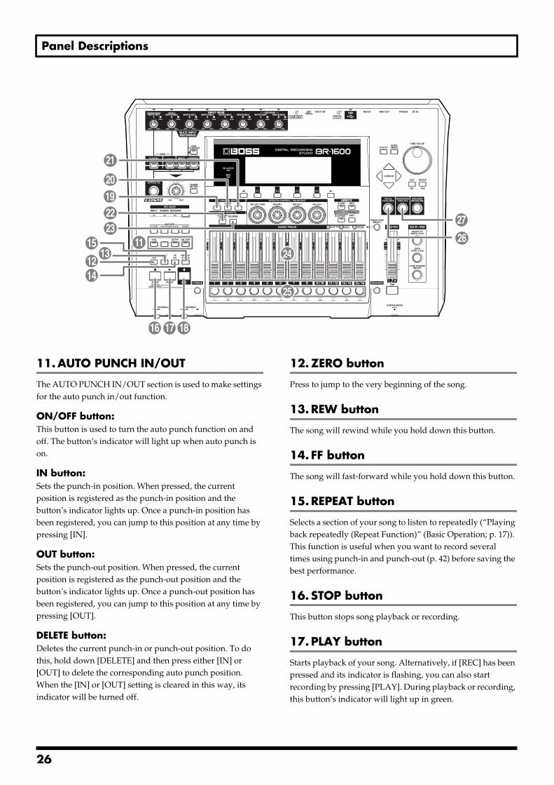
Panel Descriptions
fig.05-01b
11. AUTO PUNCH IN/OUT
The AUTO PUNCH IN/OUT section is used to make settings for the auto punch in/out function.
ON/OFF button:This button is used to turn the auto punch function on and off. The button’s indicator will light up when auto punch is on.
IN button:Sets the punch-in position. When pressed, the current position is registered as the punch-in position and the button’s indicator lights up. Once a punch-in position has been registered, you can jump to this position at any time by pressing [IN].
OUT button:Sets the punch-out position. When pressed, the current position is registered as the punch-out position and the button’s indicator lights up. Once a punch-out position has been registered, you can jump to this position at any time by pressing [OUT].
DELETE button:Deletes the current punch-in or punch-out position. To do this, hold down [DELETE] and then press either [IN] or [OUT] to delete the corresponding auto punch position. When the [IN] or [OUT] setting is cleared in this way, its indicator will be turned off.
12. ZERO button
Press to jump to the very beginning of the song.
13. REW button
The song will rewind while you hold down this button.
14. FF button
The song will fast-forward while you hold down this button.
15. REPEAT button
Selects a section of your song to listen to repeatedly (“Playing back repeatedly (Repeat Function)” (Basic Operation; p. 17)). This function is useful when you want to record several times using punch-in and punch-out (p. 42) before saving the best performance.
16. STOP button
This button stops song playback or recording.
17. PLAY button
Starts playback of your song. Alternatively, if [REC] has been pressed and its indicator is flashing, you can also start recording by pressing [PLAY]. During playback or recording, this button’s indicator will light up in green.
1115
1412
13
16 17 18
21
22
2019
23
24
25
26
27
26
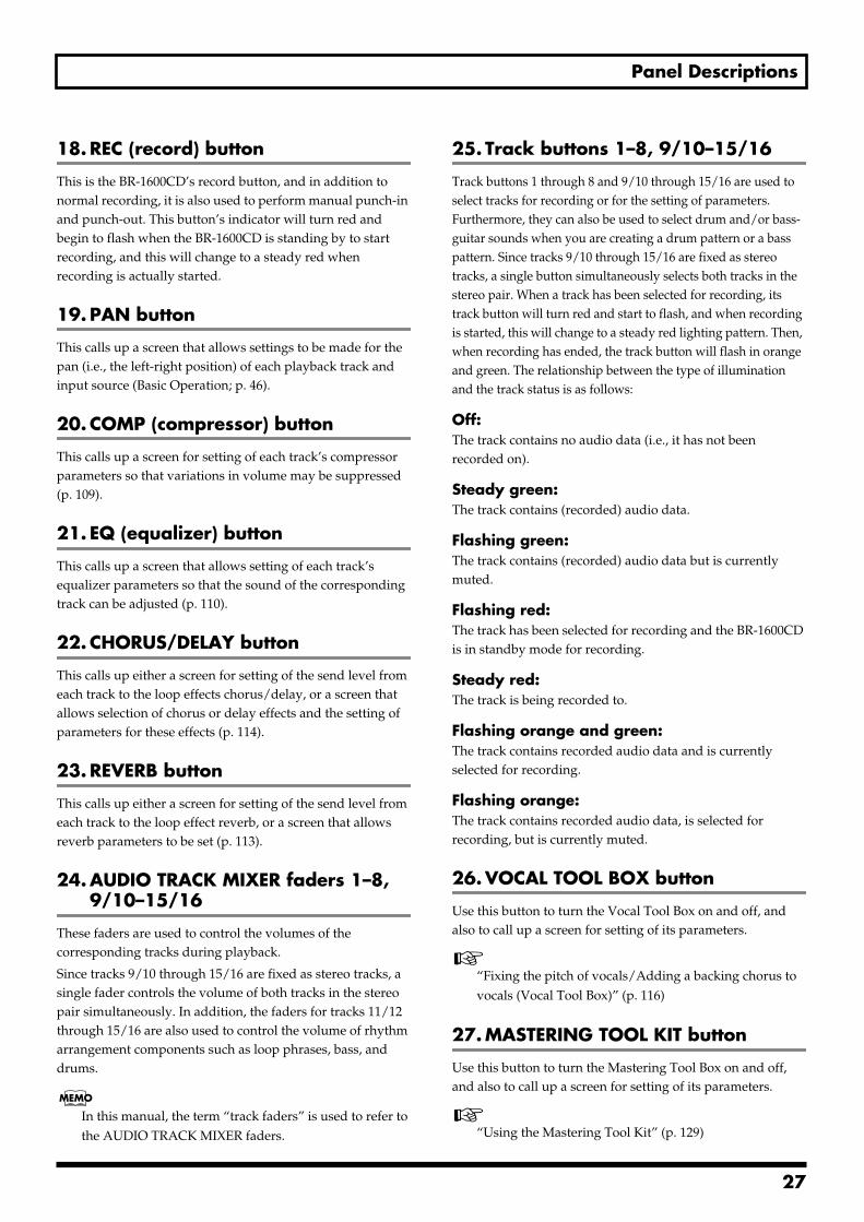
Panel Descriptions
18. REC (record) button
This is the BR-1600CD’s record button, and in addition to normal recording, it is also used to perform manual punch-in and punch-out. This button’s indicator will turn red and begin to flash when the BR-1600CD is standing by to start recording, and this will change to a steady red when recording is actually started.
19. PAN button
This calls up a screen that allows settings to be made for the pan (i.e., the left-right position) of each playback track and input source (Basic Operation; p. 46).
20. COMP (compressor) button
This calls up a screen for setting of each track’s compressor parameters so that variations in volume may be suppressed (p. 109).
21. EQ (equalizer) button
This calls up a screen that allows setting of each track’s equalizer parameters so that the sound of the corresponding track can be adjusted (p. 110).
22. CHORUS/DELAY button
This calls up either a screen for setting of the send level from each track to the loop effects chorus/delay, or a screen that allows selection of chorus or delay effects and the setting of parameters for these effects (p. 114).
23. REVERB button
This calls up either a screen for setting of the send level from each track to the loop effect reverb, or a screen that allows reverb parameters to be set (p. 113).
24. AUDIO TRACK MIXER faders 1–8, 9/10–15/16
These faders are used to control the volumes of the corresponding tracks during playback.
Since tracks 9/10 through 15/16 are fixed as stereo tracks, a single fader controls the volume of both tracks in the stereo pair simultaneously. In addition, the faders for tracks 11/12 through 15/16 are also used to control the volume of rhythm arrangement components such as loop phrases, bass, and drums.
In this manual, the term “track faders” is used to refer to the AUDIO TRACK MIXER faders.
25. Track buttons 1–8, 9/10–15/16
Track buttons 1 through 8 and 9/10 through 15/16 are used to select tracks for recording or for the setting of parameters. Furthermore, they can also be used to select drum and/or bass-guitar sounds when you are creating a drum pattern or a bass pattern. Since tracks 9/10 through 15/16 are fixed as stereo tracks, a single button simultaneously selects both tracks in the stereo pair. When a track has been selected for recording, its track button will turn red and start to flash, and when recording is started, this will change to a steady red lighting pattern. Then, when recording has ended, the track button will flash in orange and green. The relationship between the type of illumination and the track status is as follows:
Off:The track contains no audio data (i.e., it has not been recorded on).
Steady green:The track contains (recorded) audio data.
Flashing green:The track contains (recorded) audio data but is currently muted.
Flashing red:The track has been selected for recording and the BR-1600CD is in standby mode for recording.
Steady red:The track is being recorded to.
Flashing orange and green:The track contains recorded audio data and is currently selected for recording.
Flashing orange:The track contains recorded audio data, is selected for recording, but is currently muted.
26. VOCAL TOOL BOX button
Use this button to turn the Vocal Tool Box on and off, and also to call up a screen for setting of its parameters.
“Fixing the pitch of vocals/Adding a backing chorus to vocals (Vocal Tool Box)” (p. 116)
27. MASTERING TOOL KIT button
Use this button to turn the Mastering Tool Box on and off, and also to call up a screen for setting of its parameters.
“Using the Mastering Tool Kit” (p. 129)
27
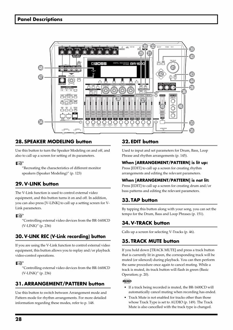
Panel Descriptions
fig.05-01c
28. SPEAKER MODELING button
Use this button to turn the Speaker Modeling on and off, and also to call up a screen for setting of its parameters.
“Recreating the characteristics of different monitor speakers (Speaker Modeling)” (p. 123)
29. V-LINK button
The V-Link function is used to control external video equipment, and this button turns it on and off. In addition, you can also press [V-LINK] to call up a setting screen for V-Link parameters.
“Controlling external video devices from the BR-1600CD (V-LINK)” (p. 236)
30. V-LINK REC (V-Link recording) button
If you are using the V-Link function to control external video equipment, this button allows you to replay and/or playback video-control operations.
“Controlling external video devices from the BR-1600CD (V-LINK)” (p. 236)
31. ARRANGEMENT/PATTERN button
Use this button to switch between Arrangement mode and Pattern mode for rhythm arrangements. For more detailed information regarding these modes, refer to p. 148.
32. EDIT button
Used to input and set parameters for Drum, Bass, Loop Phrase and rhythm arrangements (p. 145).
When [ARRANGEMENT/PATTERN] is lit up: Press [EDIT] to call up a screen for creating rhythm arrangements and editing the relevant parameters.
When [ARRANGEMENT/PATTERN] is not lit: Press [EDIT] to call up a screen for creating drum and/or bass patterns and editing the relevant parameters.
33. TAP button
By tapping this button along with your song, you can set the tempo for the Drum, Bass and Loop Phrases (p. 151).
34. V-TRACK button
Calls up a screen for selecting V-Tracks (p. 46).
35. TRACK MUTE button
If you hold down [TRACK MUTE] and press a track button that is currently lit in green, the corresponding track will be muted (or silenced) during playback. You can then perform the same procedure once again to cancel muting. While a track is muted, its track button will flash in green (Basic Operation; p. 20).
• If a track being recorded is muted, the BR-1600CD will automatically cancel muting when recording has ended.
• Track Mute is not enabled for tracks other than those whose Track Type is set to AUDIO (p. 149). The Track Mute is also cancelled with the track type is changed.
28
41
33
35
29 3130 32
34
47
48
36
3738
39
40
444342
45 46
28
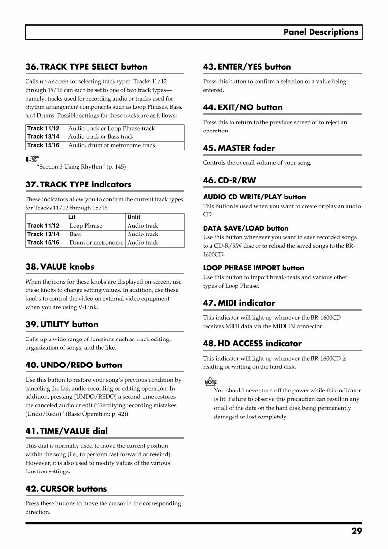
Panel Descriptions
36. TRACK TYPE SELECT button
Calls up a screen for selecting track types. Tracks 11/12 through 15/16 can each be set to one of two track types—namely, tracks used for recording audio or tracks used for rhythm arrangement components such as Loop Phrases, Bass, and Drums. Possible settings for these tracks are as follows:
“Section 3 Using Rhythm” (p. 145)
37. TRACK TYPE indicators
These indicators allow you to confirm the current track types for Tracks 11/12 through 15/16.
38. VALUE knobs
When the icons for these knobs are displayed on-screen, use these knobs to change setting values. In addition, use these knobs to control the video on external video equipment when you are using V-Link.
39. UTILITY button
Calls up a wide range of functions such as track editing, organization of songs, and the like.
40. UNDO/REDO button
Use this button to restore your song’s previous condition by canceling the last audio recording or editing operation. In addition, pressing [UNDO/REDO] a second time restores the canceled audio or edit (“Rectifying recording mistakes (Undo/Redo)” (Basic Operation; p. 42)).
41. TIME/VALUE dial
This dial is normally used to move the current position within the song (i.e., to perform fast forward or rewind). However, it is also used to modify values of the various function settings.
42. CURSOR buttons
Press these buttons to move the cursor in the corresponding direction.
43. ENTER/YES button
Press this button to confirm a selection or a value being entered.
44. EXIT/NO button
Press this to return to the previous screen or to reject an operation.
45. MASTER fader
Controls the overall volume of your song.
46. CD-R/RW
AUDIO CD WRITE/PLAY buttonThis button is used when you want to create or play an audio CD.
DATA SAVE/LOAD buttonUse this button whenever you want to save recorded songs to a CD-R/RW disc or to reload the saved songs to the BR-1600CD.
LOOP PHRASE IMPORT buttonUse this button to import break-beats and various other types of Loop Phrase.
47. MIDI indicator
This indicator will light up whenever the BR-1600CD receives MIDI data via the MIDI IN connector.
48. HD ACCESS indicator
This indicator will light up whenever the BR-1600CD is reading or writing on the hard disk.
You should never turn off the power while this indicator is lit. Failure to observe this precaution can result in any or all of the data on the hard disk being permanently damaged or lost completely.
Track 11/12 Audio track or Loop Phrase track Track 13/14 Audio track or Bass track Track 15/16 Audio, drum or metronome track
Lit UnlitTrack 11/12 Loop Phrase Audio trackTrack 13/14 Bass Audio trackTrack 15/16 Drum or metronome Audio track
29
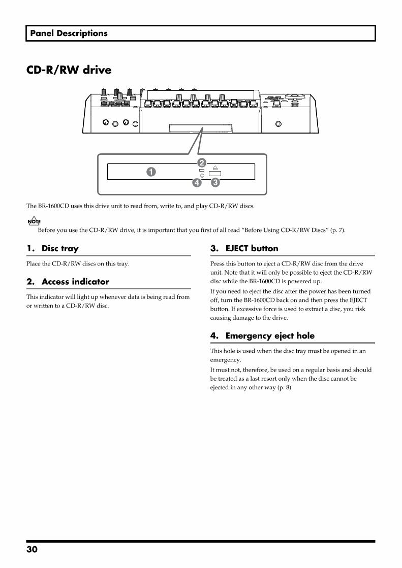
Panel Descriptions
CD-R/RW drivefig.05-02
The BR-1600CD uses this drive unit to read from, write to, and play CD-R/RW discs.
Before you use the CD-R/RW drive, it is important that you first of all read “Before Using CD-R/RW Discs” (p. 7).
1. Disc tray
Place the CD-R/RW discs on this tray.
2. Access indicator
This indicator will light up whenever data is being read from or written to a CD-R/RW disc.
3. EJECT button
Press this button to eject a CD-R/RW disc from the drive unit. Note that it will only be possible to eject the CD-R/RW disc while the BR-1600CD is powered up.
If you need to eject the disc after the power has been turned off, turn the BR-1600CD back on and then press the EJECT button. If excessive force is used to extract a disc, you risk causing damage to the drive.
4. Emergency eject hole
This hole is used when the disc tray must be opened in an emergency.
It must not, therefore, be used on a regular basis and should be treated as a last resort only when the disc cannot be ejected in any other way (p. 8).
12
34
30
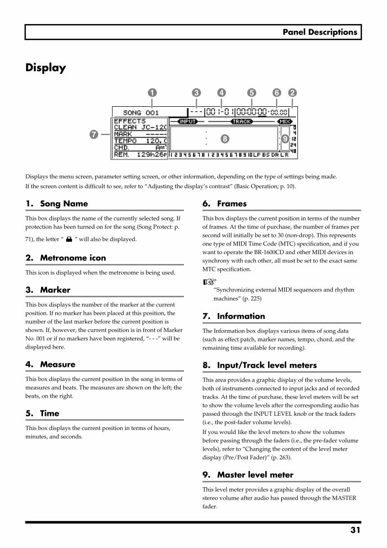
Panel Descriptions
Displayfig.05-03
Displays the menu screen, parameter setting screen, or other information, depending on the type of settings being made.
If the screen content is difficult to see, refer to “Adjusting the display’s contrast” (Basic Operation; p. 10).
1. Song Name
This box displays the name of the currently selected song. If protection has been turned on for the song (Song Protect: p.
71), the letter “ ” will also be displayed.
2. Metronome icon
This icon is displayed when the metronome is being used.
3. Marker
This box displays the number of the marker at the current position. If no marker has been placed at this position, the number of the last marker before the current position is shown. If, however, the current position is in front of Marker No. 001 or if no markers have been registered, “- - -” will be displayed here.
4. Measure
This box displays the current position in the song in terms of measures and beats. The measures are shown on the left; the beats, on the right.
5. Time
This box displays the current position in terms of hours, minutes, and seconds.
6. Frames
This box displays the current position in terms of the number of frames. At the time of purchase, the number of frames per second will initially be set to 30 (non-drop). This represents one type of MIDI Time Code (MTC) specification, and if you want to operate the BR-1600CD and other MIDI devices in synchrony with each other, all must be set to the exact same MTC specification.
“Synchronizing external MIDI sequencers and rhythm machines” (p. 225)
7. Information
The Information box displays various items of song data (such as effect patch, marker names, tempo, chord, and the remaining time available for recording).
8. Input/Track level meters
This area provides a graphic display of the volume levels, both of instruments connected to input jacks and of recorded tracks. At the time of purchase, these level meters will be set to show the volume levels after the corresponding audio has passed through the INPUT LEVEL knob or the track faders (i.e., the post-fader volume levels).
If you would like the level meters to show the volumes before passing through the faders (i.e., the pre-fader volume levels), refer to “Changing the content of the level meter display (Pre/Post Fader)” (p. 263).
9. Master level meter
This level meter provides a graphic display of the overall stereo volume after audio has passed through the MASTER fader.
1
7 8
3 4 5 6 2
9
31
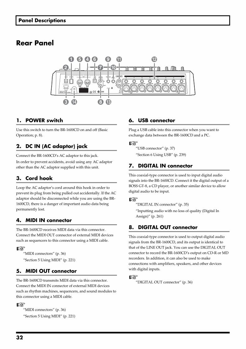
Panel Descriptions
Rear Panelfig.05-04
1. POWER switch
Use this switch to turn the BR-1600CD on and off (Basic Operation; p. 8).
2. DC IN (AC adaptor) jack
Connect the BR-1600CD’s AC adaptor to this jack.
In order to prevent accidents, avoid using any AC adaptor other than the AC adaptor supplied with this unit.
3. Cord hook
Loop the AC adaptor’s cord around this hook in order to prevent its plug from being pulled out accidentally. If the AC adaptor should be disconnected while you are using the BR-1600CD, there is a danger of important audio data being permanently lost.
4. MIDI IN connector
The BR-1600CD receives MIDI data via this connector. Connect the MIDI OUT connector of external MIDI devices such as sequencers to this connector using a MIDI cable.
“MIDI connectors” (p. 36)
“Section 5 Using MIDI” (p. 221)
5. MIDI OUT connector
The BR-1600CD transmits MIDI data via this connector. Connect the MIDI IN connector of external MIDI devices such as rhythm machines, sequencers, and sound modules to this connector using a MIDI cable.
“MIDI connectors” (p. 36)
“Section 5 Using MIDI” (p. 221)
6. USB connector
Plug a USB cable into this connector when you want to exchange data between the BR-1600CD and a PC.
“USB connector” (p. 37)
“Section 6 Using USB” (p. 239)
7. DIGITAL IN connector
This coaxial-type connector is used to input digital audio signals into the BR-1600CD. Connect it the digital output of a BOSS GT-8, a CD player, or another similar device to allow digital audio to be input.
“DIGITAL IN connector” (p. 35)
“Inputting audio with no loss of quality (Digital In Assign)” (p. 261)
8. DIGITAL OUT connector
This coaxial-type connector is used to output digital audio signals from the BR-1600CD, and its output is identical to that of the LINE OUT jack. You can use the DIGITAL OUT connector to record the BR-1600CD’s output on CD-R or MD recorders. In addition, it can also be used to make connections with amplifiers, speakers, and other devices with digital inputs.
“DIGITAL OUT connector” (p. 36)
1
10
4 6 95
2
3
7
8 1314
11 12
32
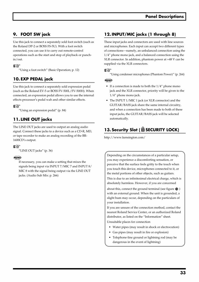
Panel Descriptions
9. FOOT SW jack
Use this jack to connect a separately sold foot switch (such as the Roland DP-2 or BOSS FS-5U). With a foot switch connected, you can use it to carry out remote-control operations such as the start and stop of playback or punch-in/out.
“Using a foot switch” (Basic Operation; p. 12)
10. EXP PEDAL jack
Use this jack to connect a separately sold expression pedal (such as the Roland EV-5 or BOSS FV-500L/FV-500H). When connected, an expression pedal allows you to use the internal effects processor’s pedal wah and other similar effects.
“Using an expression pedal” (p. 84)
11. LINE OUT jacks
The LINE OUT jacks are used to output an analog audio signal. Connect these jacks to a device such as a CD-R, MD, or tape recorder to make an analog recording of the BR-1600CD’s output.
“LINE OUT jacks” (p. 36)
If necessary, you can make a setting that mixes the signals being input via INPUT 7/MIC 7 and INPUT 8/MIC 8 with the signal being output via the LINE OUT jacks. (Audio Sub Mix: p. 266)
12. INPUT/MIC jacks (1 through 8)
These input jacks and connectors are used with line sources and microphones. Each input can accept two different types of connections—namely, an unbalanced connection using the 1/4” phone mono jack, and a balanced connection using the XLR connector. In addition, phantom power at +48 V can be supplied via the XLR connectors.
“Using condenser microphones (Phantom Power)” (p. 264)
• If a connection is made to both the 1/4” phone mono jack and the XLR connector, priority will be given to the 1/4” phone mono jack.
• The INPUT 1/MIC 1 jack (or XLR connector) and the GUITAR/BASS jack share the same internal circuitry, and when a connection has been made to both of these input jacks, the GUITAR/BASS jack will be selected automatically.
13. Security Slot ( SECURITY LOCK)
http://www.kensington.com/
Depending on the circumstances of a particular setup, you may experience a discomforting sensation, or perceive that the surface feels gritty to the touch when you touch this device, microphones connected to it, or the metal portions of other objects, such as guitars.
This is due to an infinitesimal electrical charge, which is absolutely harmless. However, if you are concerned
about this, connect the ground terminal (see figure ) with an external ground. When the unit is grounded, a slight hum may occur, depending on the particulars of your installation.
If you are unsure of the connection method, contact the nearest Roland Service Center, or an authorized Roland distributor, as listed on the “Information” sheet.
Unsuitable places for connection
• Water pipes (may result in shock or electrocution)
• Gas pipes (may result in fire or explosion)
• Telephone-line ground or lightning rod (may be dangerous in the event of lightning)
14
33
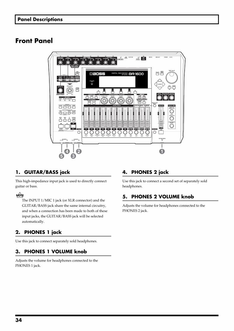
Panel Descriptions
Front Panelfig.05-05
1. GUITAR/BASS jack
This high-impedance input jack is used to directly connect guitar or bass.
The INPUT 1/MIC 1 jack (or XLR connector) and the GUITAR/BASS jack share the same internal circuitry, and when a connection has been made to both of these input jacks, the GUITAR/BASS jack will be selected automatically.
2. PHONES 1 jack
Use this jack to connect separately sold headphones.
3. PHONES 1 VOLUME knob
Adjusts the volume for headphones connected to the PHONES 1 jack.
4. PHONES 2 jack
Use this jack to connect a second set of separately sold headphones.
5. PHONES 2 VOLUME knob
Adjusts the volume for headphones connected to the PHONES 2 jack.
123
45
34
Extra information on jacks and connectors
Input jacks and connectorsThese jacks and connectors are used to input audio to the BR-1600CD.
GUITAR/BASS jackThis high-impedance input jack (1/4” phone plug type) is used to directly connect guitar or bass.
You can use this jack whenever INPUT SELECT [GUITAR/BASS], [MULTI-TRACK], or [STEREO TRACKS] is currently turned on. Note that this input uses the same internal circuitry as the INPUT 1/MIC 1 jack and its volume can be adjusted using the INPUT SENS 1 knob. When an instrument is connected to the GUITAR/BASS jack, this input source will be given priority and the INPUT 1/MIC 1 jack will be deactivated. If you want to use the BR-1600CD’s guitar bank effects as an insert effect for a guitar or bass, connect the instrument to this jack, and then press INPUT SELECT [GUITAR/BASS].
When a guitar or bass is connected, noise may be generated if its pickup is moved close to the BR-1600CD. In addition, a similar type of noise can also occur if the instrument is located close to fluorescent lights, a CRT, a PC, or any other type of electronic device. This noise occurs when the instrument picks up magnetic noise generated in electronic devices via its pickup, and if it becomes noticeable, move the pickup away from the electronic device.
INPUT 1/MIC 1 jackThese inputs (1/4” phone plug and XLR connector types) are used with line sources and microphones. The 1/4” phone plug-type jack is used to input unbalanced signals; the XLR type connector, to input balanced signals. In addition, the XLR connector can also supply phantom power.
You can use this input whenever INPUT SELECT [GUITAR/BASS], [MULTI-TRACK], or [STEREO TRACKS] is currently turned on.
Note that this input uses the same internal circuitry as the GUITAR/BASS jack, and when an instrument is connected to the GUITAR/BASS jack, that input source will be given priority and the INPUT 1/MIC 1 jack will be deactivated.
INPUT 2/MIC 2 jackThese inputs (1/4” phone plug and XLR connector types) are used with line sources and microphones. The 1/4” phone plug type jack is used to input unbalanced signals; the XLR type connector, to input balanced signals. In addition, the XLR connector can also supply phantom power.
You can use this input whenever INPUT SELECT [VOCAL], [MULTI-TRACK], or [STEREO TRACKS] is currently turned on.
If you want to use the BR-1600CD’s MIC bank effects as an insert effect for a vocal mic, connect the microphone to this input, and then press [VOCAL] from INPUT SELECT.
INPUT 3/MIC 3 jack through INPUT 8/MIC 8 jackThese inputs (1/4” phone plug and XLR connector types) are used with line sources and microphones. The 1/4” phone plug type jack is used to input unbalanced signals; the XLR type connector, to input balanced signals. In addition, the XLR connector can also supply phantom power.
You can use this input whenever INPUT SELECT [MULTI-TRACK] or [STEREO TRACKS] is currently turned on.
Note that the INPUT 7/MIC 7 and INPUT 8/MIC 8 jacks can also be used to input audio signals for an Audio Sub Mix. Whenever Audio Sub Mix is turned on, the audio signals being input via the INPUT 7/MIC 7 and INPUT 8/MIC 8 jacks will be output directly via the MASTER track L/R.
“Mixing audio-device output with the BR-1600CD’s output (Audio Sub Mix)” (p. 266)
DIGITAL IN connectorThis coaxial-type connector is used to input digital audio to the BR-1600CD. Connect the digital audio output of a CD player, BOSS GT-8, or BOSS GS-10 to this connector if you want to record from that device with no deterioration of sound quality as would occur in analog lines.
Only digital audio data of the S/PDIF format can be input via this connector; furthermore, the data must have a sample rate of 44.1 kHz and a bit depth of 16 or 24 bits. The destination for audio entering via the DIGITAL IN connector is determined by system parameter settings. Note that the INPUT SENS knobs cannot be used to adjust the volume of the audio being input via this connector. To do this, either adjust the volume of the digital device providing the audio signal or use the BR-1600CD’s INPUT LEVEL knob or LEVEL CALIBRATION function.
It is important to note that standard audio cables cannot be used with the DIGITAL IN connector and that a commercially available digital-audio cable or video cable should be used for this purpose.
35
Extra information on jacks and connectors
Output jacks and connectorsThese jacks and connectors are used to output audio from the BR-1600CD.
LINE OUT jacksThe LINE OUT jacks (stereo RCA phono plug type) are used to output audio in stereo and at line level. The BR-1600CD’s playback audio, performance of drum, bass, Loop Phrase, and monitored input will all be mixed into this output signal. In addition, playback from the CD-R/RW drive built into the BR-1600CD will also be output here. Use the LINE OUT jacks to make connections with external audio amplifiers.
Note that the audio output via the LINE OUT jack is also output via the PHONES 1 jack.
DIGITAL OUT connectorThis coaxial-type connector is used to output digital audio signals, and its output is identical to that of the LINE OUT jack.
Since digital signals do not suffer from the same type of deterioration as occurs in analog lines, they can be recorded without degradation in the quality of your audio on external digital audio devices such as CD-R, MD, and DAT recorders. In addition, if you are using Roland DS-30A Bi-Amp Monitor to monitor your sound, audio signals can be output to the speakers via this connector.
It is important to note that standard audio cables cannot be used with the DIGITAL OUT connector and that a commercially available digital-audio cable or video cable should be used for this purpose.
PHONES 1 and PHONES 2 jackAllow you to connect a pair of headphones (with a 1/4” phone stereo plug).
MIDI connectorsThe BR-1600CD features both MIDI OUT and MIDI IN connectors in order that MIDI data may be transmitted and received.
MIDI IN connectorThis 5-pin DIN type connector is used to receive MIDI data from other MIDI devices such as rhythm machines and sequencers. Connect the MIDI OUT connector of the external device to this connector using a MIDI cable.
MIDI OUT connectorThis 5-pin DIN type connector is used to transmit MIDI data from the BR-1600CD. Connect the MIDI IN connector of external MIDI devices such as rhythm machines, sequencers, and sound modules to this connector using a MIDI cable.
In order to ensure that the BR-1600CD operates correctly, do not create such a loop by, for example, connecting a single MIDI cable between its MIDI IN and MIDI OUT connectors. A MIDI loop is created when MIDI data transmitted from a MIDI OUT connector is returned without modification to the MIDI IN connector in the same system, and this can cause devices to operate abnormally.
36
Extra information on jacks and connectors
USB connectorThis B-type connector is used to connect with a host computer. (USB: Universal Serial Bus)
The BR-1600CD is compatible with USB version 1.1. By connecting it with the USB connector of a PC using a commercially available USB cable, you can transfer song data, .wav files and other similar information between the PC and the BR-1600CD. In addition, this also allows you to backup song data and the like on your PC’s hard disk.
“Section 6 Using USB” (p. 239)
When a connection is made using USB, you will be able to access the data on the BR-1600CD’s hard disk from your PC. Accordingly, there is an increased danger of accidentally damaging or deleting the BR-1600CD data. Extra special care must be taken in such a situation as data damaged or lost in this way cannot be restored. Please also note that BOSS/Roland will accept no responsibility for the repair of damaged data or for compensation for lost or damaged data.
The BR-1600CD can be used neither as a USB host nor a USB hub. As a result, you will not be able to use the USB connector to access external hard disks, CD-R/RW drives, or other similar types of USB device. Furthermore, this USB connector cannot be used with an audio interface or the like.
Power supply
DC IN (AC adaptor) jackConnect the BR-1600CD’s AC adaptor to this jack.
In order to prevent accidents, avoid using any AC adaptor other than the AC adaptor supplied with this unit. Failure to observe this precaution can result in the outbreak of fire or electrical shock. Note also that usage of any other type of AC adaptor can result in the permanent damage of the BR-1600CD itself, the hard disk, or the CD-R/RW drive. It is important, therefore, that the appropriate care be taken.
If you disconnect the AC adaptor while the BR-1600CD is reading from or writing to its hard disk (i.e., when the HD ACCESS indicator is lit), the hard disk will be irrepairably damaged. If a hard disk is damaged in this way, you will be no longer able to use it for recording, playback, song saving, or song loading; furthermore, there is a high probability that valuable data will be lost. Be sure, therefore, to loop the AC adaptor’s cord around the cord hook to prevent it being accidentally pulled out during operation of the BR-1600CD.
37
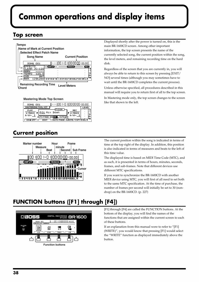
3
Common operations and display items
Top screenfig.06-01d Displayed shortly after the power is turned on, this is the
main BR-1600CD screen. Among other important information, the top screen presents the name of the currently selected song, the current position within the song, the level meters, and remaining recording time on the hard disk.
Regardless of the screen that you are currently in, you will always be able to return to this screen by pressing [EXIT/NO] several times (although you may sometimes have to wait until the BR-1600CD completes the current process).
Unless otherwise specified, all procedures described in this manual will require you to return first of all to the top screen.
In Mastering mode only, the top screen changes to the screen like that shown to the left.
Current positionfig.06-02d The current position within the song is indicated in terms of
time at the top right of the display. In addition, this position is also indicated in terms of measures and beats to the left of this time value.
The displayed time is based on MIDI Time Code (MTC), and as such, it is presented in terms of hours, minutes, seconds, frames, and sub-frames. Note that different devices use different MTC specifications.
If you want to synchronize the BR-1600CD with another MIDI device using MTC, you will first of all need to set both to the same MTC specification. At the time of purchase, the number of frames per second will initially be set to 30 (non-drop) on the BR-1600CD. (p. 227)
FUNCTION buttons ([F1] through [F4])fig.06-04 [F1] through [F4] are called the FUNCTION buttons. At the
bottom of the display, you will find the names of the functions that are assigned within the current screen to each of these buttons.
If an explanation from this manual were to refer to “[F1] (WRITE)”, you would know that pressing [F1] would select the “WRITE” function as displayed immediately above the button.
Song Name Current Position
Level Meters
Selected Effect Patch Name
Remaining Recording Time
Name of Mark at Current Position
Chord
Tempo
Mastering Mode Top Screen
Marker numberMeasure
Beat
Hour Frameminute
Second Sub Frame
Cursor
Function buttons
8
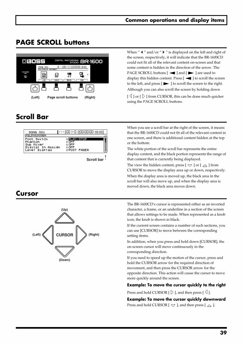
Common operations and display items
PAGE SCROLL buttonsfig.06-06 When “ ” and/or “ ” is displayed on the left and right of
the screen, respectively, it will indicate that the BR-1600CD could not fit all of the relevant content on-screen and that some content is hidden in the direction of the arrow. The PAGE SCROLL buttons [ ] and [ ] are used to display this hidden content. Press [ ] to scroll the screen to the left, and press [ ] to scroll the screen to the right.
Although you can also scroll the screen by holding down
[ ] or [ ] from CURSOR, this can be done much quicker using the PAGE SCROLL buttons.
Scroll Barfig.06-01d When you see a scroll bar at the right of the screen, it means
that the BR-1600CD could not fit all of the relevant content in one screen, and there is additional content hidden at the top or the bottom.
The white portion of the scroll bar represents the entire display content, and the black portion represents the range of that content that is currently being displayed.
The view the hidden content, press [ ] or [ ] from CURSOR to move the display area up or down, respectively.
When the display area is moved up, the black area in the scroll bar will also move up, and when the display area is moved down, the black area moves down.
Cursorfig.06-03 The BR-1600CD’s cursor is represented either as an inverted
character, a frame, or an underline in a section of the screen that allows settings to be made. When represented as a knob icon, the knob is shown in black.
If the current screen contains a number of such sections, you can use [CURSOR] to move between the corresponding setting items.
In addition, when you press and hold down [CURSOR], the on-screen cursor will move continuously in the corresponding direction.
If you need to speed up the motion of the cursor, press and hold the CURSOR arrow for the required direction of movement, and then press the CURSOR arrow for the opposite direction. This action will cause the cursor to move more quickly around the screen.
Example: To move the cursor quickly to the right
Press and hold CURSOR [ ], and then press [ ].
Example: To move the cursor quickly downward Press and hold CURSOR [ ], and then press [ ].
Page scroll buttons(Left) (Right)
Scroll bar
(Up)
(Left) (Right)
(Down)
39
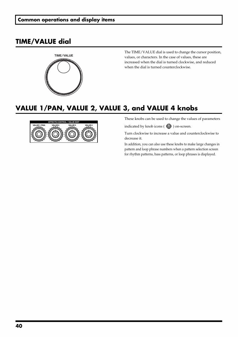
Common operations and display items
TIME/VALUE dialfig.06-05 The TIME/VALUE dial is used to change the cursor position,
values, or characters. In the case of values, these are increased when the dial is turned clockwise, and reduced when the dial is turned counterclockwise.
VALUE 1/PAN, VALUE 2, VALUE 3, and VALUE 4 knobsfig.06-07 These knobs can be used to change the values of parameters
indicated by knob icons ( ) on-screen.
Turn clockwise to increase a value and counterclockwise to decrease it.
In addition, you can also use these knobs to make large changes in pattern and loop phrase numbers when a pattern selection screen for rhythm patterns, bass patterns, or loop phrases is displayed.
40

Section 1 Advanced Use
Section 1Advanced Use
41
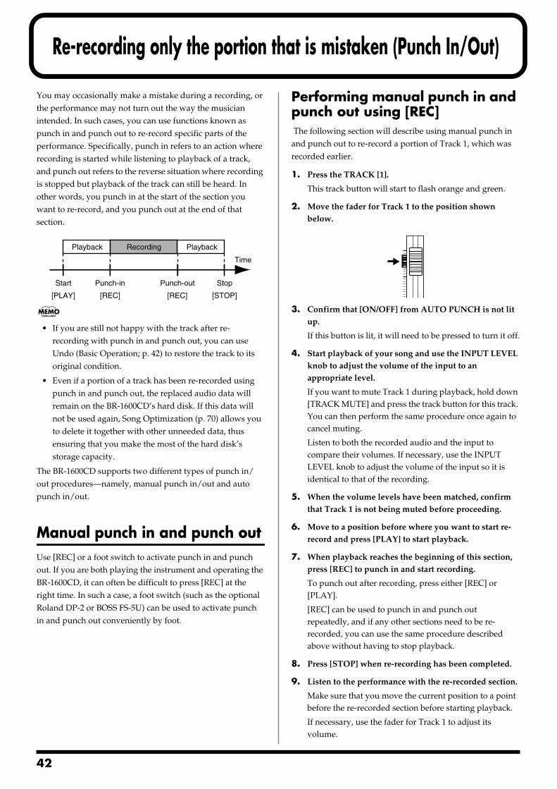
4
Re-recording only the portion that is mistaken (Punch In/Out)
You may occasionally make a mistake during a recording, or the performance may not turn out the way the musician intended. In such cases, you can use functions known as punch in and punch out to re-record specific parts of the performance. Specifically, punch in refers to an action where recording is started while listening to playback of a track, and punch out refers to the reverse situation where recording is stopped but playback of the track can still be heard. In other words, you punch in at the start of the section you want to re-record, and you punch out at the end of that section.fig.10-01
• If you are still not happy with the track after re-recording with punch in and punch out, you can use Undo (Basic Operation; p. 42) to restore the track to its original condition.
• Even if a portion of a track has been re-recorded using punch in and punch out, the replaced audio data will remain on the BR-1600CD’s hard disk. If this data will not be used again, Song Optimization (p. 70) allows you to delete it together with other unneeded data, thus ensuring that you make the most of the hard disk’s storage capacity.
The BR-1600CD supports two different types of punch in/out procedures—namely, manual punch in/out and auto punch in/out.
Manual punch in and punch outUse [REC] or a foot switch to activate punch in and punch out. If you are both playing the instrument and operating the BR-1600CD, it can often be difficult to press [REC] at the right time. In such a case, a foot switch (such as the optional Roland DP-2 or BOSS FS-5U) can be used to activate punch in and punch out conveniently by foot.
Performing manual punch in and punch out using [REC] The following section will describe using manual punch in and punch out to re-record a portion of Track 1, which was recorded earlier.
1. Press the TRACK [1].
This track button will start to flash orange and green.
2. Move the fader for Track 1 to the position shown below.
fig.10-02
3. Confirm that [ON/OFF] from AUTO PUNCH is not lit up.
If this button is lit, it will need to be pressed to turn it off.
4. Start playback of your song and use the INPUT LEVEL knob to adjust the volume of the input to an appropriate level.
If you want to mute Track 1 during playback, hold down [TRACK MUTE] and press the track button for this track. You can then perform the same procedure once again to cancel muting.
Listen to both the recorded audio and the input to compare their volumes. If necessary, use the INPUT LEVEL knob to adjust the volume of the input so it is identical to that of the recording.
5. When the volume levels have been matched, confirm that Track 1 is not being muted before proceeding.
6. Move to a position before where you want to start re-record and press [PLAY] to start playback.
7. When playback reaches the beginning of this section, press [REC] to punch in and start recording.
To punch out after recording, press either [REC] or [PLAY].
[REC] can be used to punch in and punch out repeatedly, and if any other sections need to be re-recorded, you can use the same procedure described above without having to stop playback.
8. Press [STOP] when re-recording has been completed.
9. Listen to the performance with the re-recorded section.
Make sure that you move the current position to a point before the re-recorded section before starting playback.
If necessary, use the fader for Track 1 to adjust its volume.
Time
Punch-in StopStart
[PLAY] [REC] [REC] [STOP]
Punch-out
Playback PlaybackRecording
2
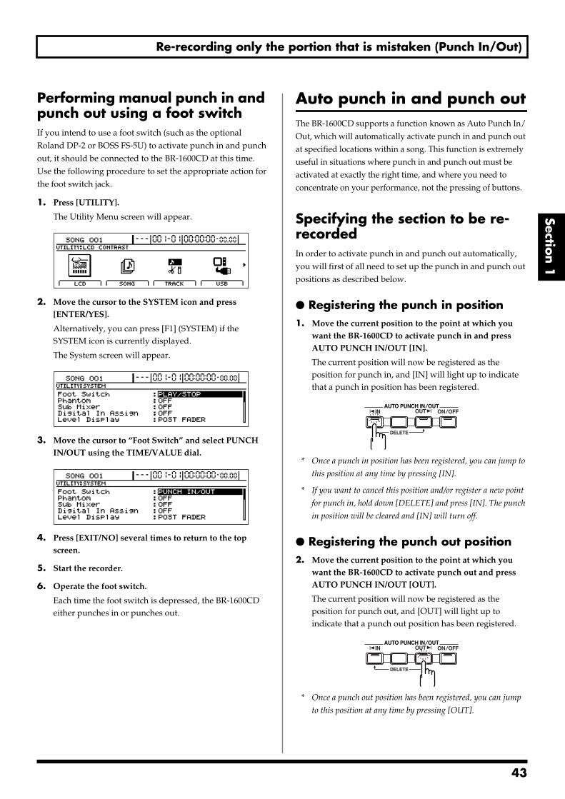
Re-recording only the portion that is mistaken (Punch In/Out)
Section 1
Performing manual punch in and punch out using a foot switchIf you intend to use a foot switch (such as the optional Roland DP-2 or BOSS FS-5U) to activate punch in and punch out, it should be connected to the BR-1600CD at this time. Use the following procedure to set the appropriate action for the foot switch jack.
1. Press [UTILITY].
The Utility Menu screen will appear.fig.12-12d
2. Move the cursor to the SYSTEM icon and press [ENTER/YES].
Alternatively, you can press [F1] (SYSTEM) if the SYSTEM icon is currently displayed.
The System screen will appear.fig.10-03d
3. Move the cursor to “Foot Switch” and select PUNCH IN/OUT using the TIME/VALUE dial.
fig.10-04d
4. Press [EXIT/NO] several times to return to the top screen.
5. Start the recorder.
6. Operate the foot switch.
Each time the foot switch is depressed, the BR-1600CD either punches in or punches out.
Auto punch in and punch outThe BR-1600CD supports a function known as Auto Punch In/Out, which will automatically activate punch in and punch out at specified locations within a song. This function is extremely useful in situations where punch in and punch out must be activated at exactly the right time, and where you need to concentrate on your performance, not the pressing of buttons.
Specifying the section to be re-recorded In order to activate punch in and punch out automatically, you will first of all need to set up the punch in and punch out positions as described below.
Registering the punch in position1. Move the current position to the point at which you
want the BR-1600CD to activate punch in and press AUTO PUNCH IN/OUT [IN].
The current position will now be registered as the position for punch in, and [IN] will light up to indicate that a punch in position has been registered.
fig.10-05
* Once a punch in position has been registered, you can jump to
this position at any time by pressing [IN].
* If you want to cancel this position and/or register a new point
for punch in, hold down [DELETE] and press [IN]. The punch
in position will be cleared and [IN] will turn off.
Registering the punch out position 2. Move the current position to the point at which you
want the BR-1600CD to activate punch out and press AUTO PUNCH IN/OUT [OUT].
The current position will now be registered as the position for punch out, and [OUT] will light up to indicate that a punch out position has been registered.
fig.10-06
* Once a punch out position has been registered, you can jump
to this position at any time by pressing [OUT].
43
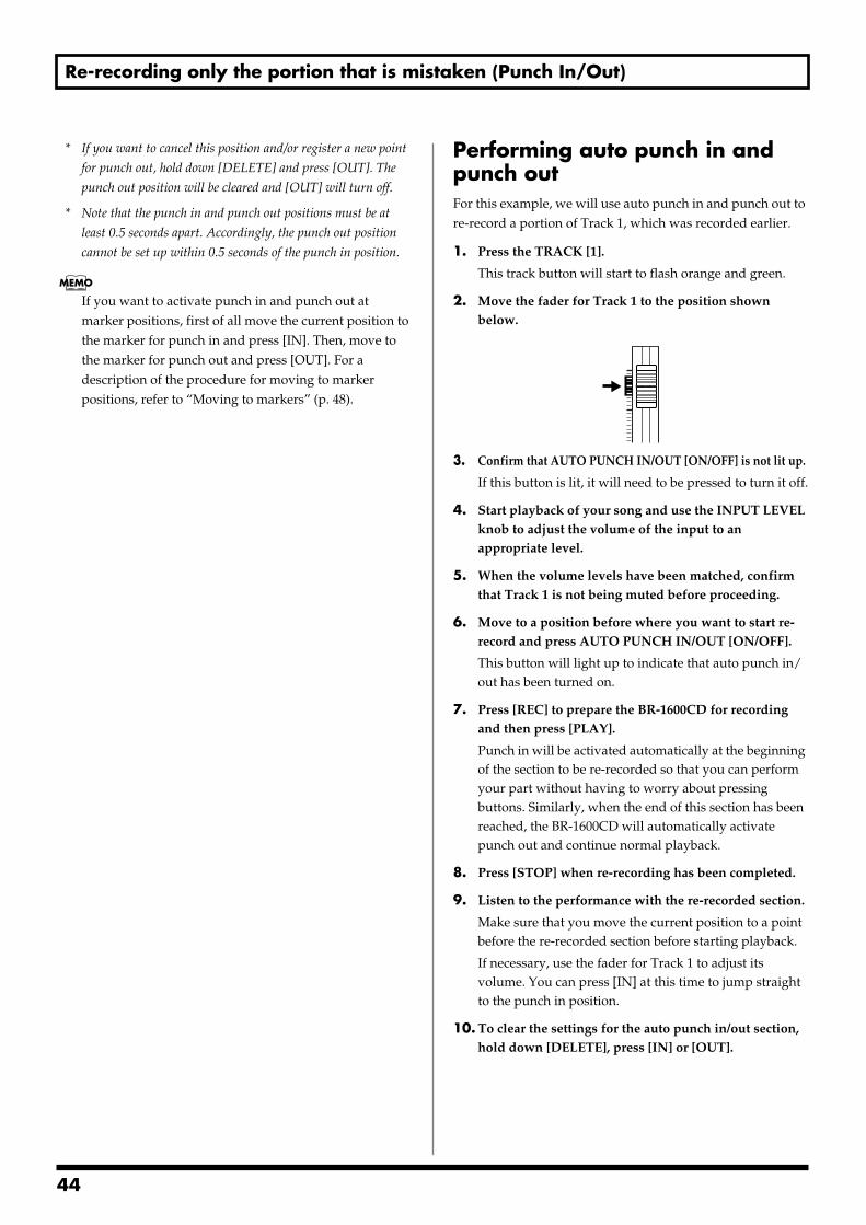
Re-recording only the portion that is mistaken (Punch In/Out)
* If you want to cancel this position and/or register a new point
for punch out, hold down [DELETE] and press [OUT]. The
punch out position will be cleared and [OUT] will turn off.
* Note that the punch in and punch out positions must be at
least 0.5 seconds apart. Accordingly, the punch out position
cannot be set up within 0.5 seconds of the punch in position.
If you want to activate punch in and punch out at marker positions, first of all move the current position to the marker for punch in and press [IN]. Then, move to the marker for punch out and press [OUT]. For a description of the procedure for moving to marker positions, refer to “Moving to markers” (p. 48).
Performing auto punch in and punch out For this example, we will use auto punch in and punch out to re-record a portion of Track 1, which was recorded earlier.
1. Press the TRACK [1].
This track button will start to flash orange and green.
2. Move the fader for Track 1 to the position shown below.
fig.10-02
3. Confirm that AUTO PUNCH IN/OUT [ON/OFF] is not lit up.
If this button is lit, it will need to be pressed to turn it off.
4. Start playback of your song and use the INPUT LEVEL knob to adjust the volume of the input to an appropriate level.
5. When the volume levels have been matched, confirm that Track 1 is not being muted before proceeding.
6. Move to a position before where you want to start re-record and press AUTO PUNCH IN/OUT [ON/OFF].
This button will light up to indicate that auto punch in/out has been turned on.
7. Press [REC] to prepare the BR-1600CD for recording and then press [PLAY].
Punch in will be activated automatically at the beginning of the section to be re-recorded so that you can perform your part without having to worry about pressing buttons. Similarly, when the end of this section has been reached, the BR-1600CD will automatically activate punch out and continue normal playback.
8. Press [STOP] when re-recording has been completed.
9. Listen to the performance with the re-recorded section.
Make sure that you move the current position to a point before the re-recorded section before starting playback.
If necessary, use the fader for Track 1 to adjust its volume. You can press [IN] at this time to jump straight to the punch in position.
10. To clear the settings for the auto punch in/out section, hold down [DELETE], press [IN] or [OUT].
44
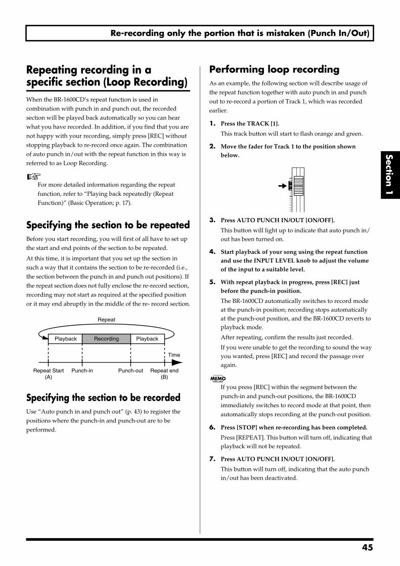
Re-recording only the portion that is mistaken (Punch In/Out)
Section 1
Repeating recording in a specific section (Loop Recording) When the BR-1600CD’s repeat function is used in combination with punch in and punch out, the recorded section will be played back automatically so you can hear what you have recorded. In addition, if you find that you are not happy with your recording, simply press [REC] without stopping playback to re-record once again. The combination of auto punch in/out with the repeat function in this way is referred to as Loop Recording.
For more detailed information regarding the repeat function, refer to “Playing back repeatedly (Repeat Function)” (Basic Operation; p. 17).
Specifying the section to be repeatedBefore you start recording, you will first of all have to set up the start and end points of the section to be repeated.
At this time, it is important that you set up the section in such a way that it contains the section to be re-recorded (i.e., the section between the punch in and punch out positions). If the repeat section does not fully enclose the re-record section, recording may not start as required at the specified position or it may end abruptly in the middle of the re- record section.fig.10-07
Specifying the section to be recordedUse “Auto punch in and punch out” (p. 43) to register the positions where the punch-in and punch-out are to be performed.
Performing loop recordingAs an example, the following section will describe usage of the repeat function together with auto punch in and punch out to re-record a portion of Track 1, which was recorded earlier.
1. Press the TRACK [1].
This track button will start to flash orange and green.
2. Move the fader for Track 1 to the position shown below.
fig.10-02
3. Press AUTO PUNCH IN/OUT [ON/OFF].
This button will light up to indicate that auto punch in/out has been turned on.
4. Start playback of your song using the repeat function and use the INPUT LEVEL knob to adjust the volume of the input to a suitable level.
5. With repeat playback in progress, press [REC] just before the punch-in position.
The BR-1600CD automatically switches to record mode at the punch-in position; recording stops automatically at the punch-out position, and the BR-1600CD reverts to playback mode.
After repeating, confirm the results just recorded.
If you were unable to get the recording to sound the way you wanted, press [REC] and record the passage over again.
If you press [REC] within the segment between the punch-in and punch-out positions, the BR-1600CD immediately switches to record mode at that point, then automatically stops recording at the punch-out position.
6. Press [STOP] when re-recording has been completed.
Press [REPEAT]. This button will turn off, indicating that playback will not be repeated.
7. Press AUTO PUNCH IN/OUT [ON/OFF].
This button will turn off, indicating that the auto punch in/out has been deactivated.
PlaybackPlayback
Repeat
Repeat Start(A)
Punch-in Punch-out Repeat end(B)
Time
Recording
45
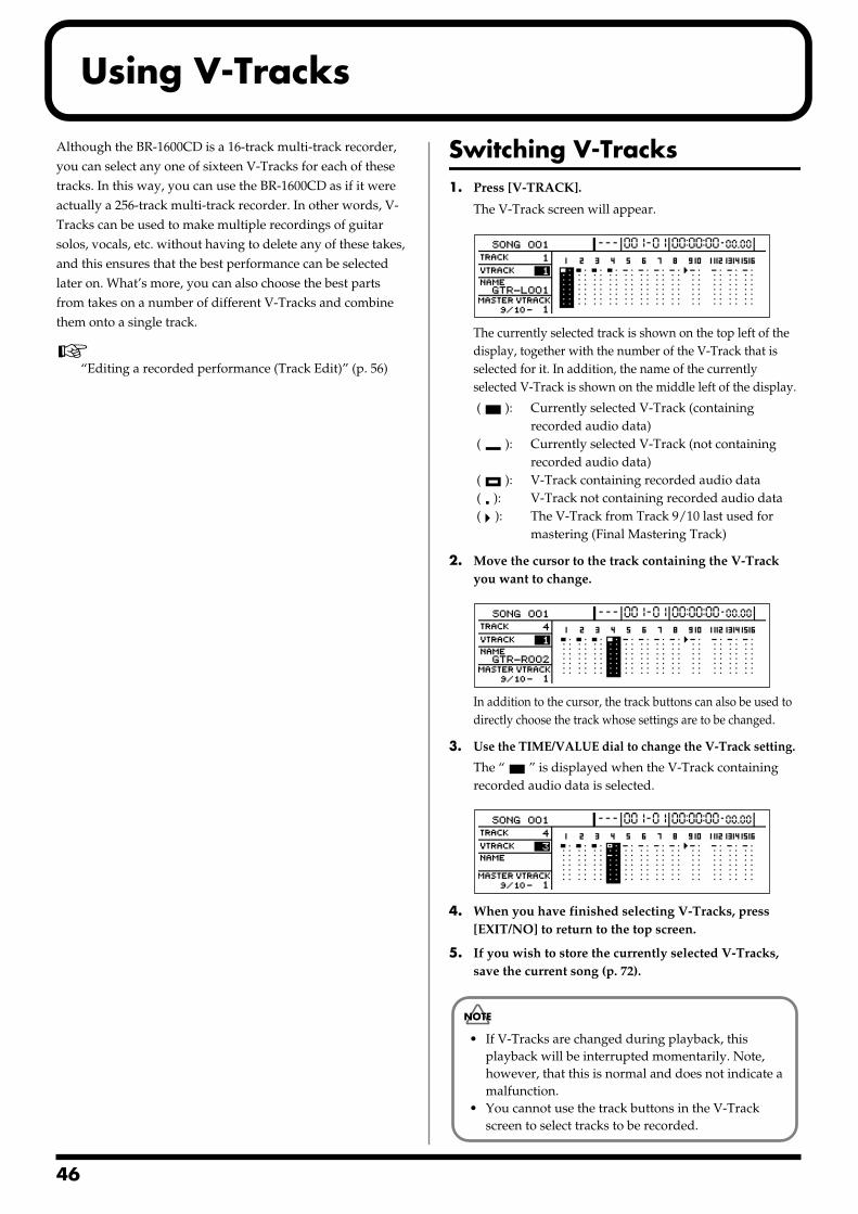
4
Using V-Tracks
Although the BR-1600CD is a 16-track multi-track recorder, you can select any one of sixteen V-Tracks for each of these tracks. In this way, you can use the BR-1600CD as if it were actually a 256-track multi-track recorder. In other words, V-Tracks can be used to make multiple recordings of guitar solos, vocals, etc. without having to delete any of these takes, and this ensures that the best performance can be selected later on. What’s more, you can also choose the best parts from takes on a number of different V-Tracks and combine them onto a single track.
“Editing a recorded performance (Track Edit)” (p. 56)
Switching V-Tracks1. Press [V-TRACK].
The V-Track screen will appear.fig.11-01d
The currently selected track is shown on the top left of the display, together with the number of the V-Track that is selected for it. In addition, the name of the currently selected V-Track is shown on the middle left of the display.
( ): Currently selected V-Track (containing recorded audio data)
( ): Currently selected V-Track (not containing recorded audio data)
( ): V-Track containing recorded audio data ( ): V-Track not containing recorded audio data ( ): The V-Track from Track 9/10 last used for
mastering (Final Mastering Track)
2. Move the cursor to the track containing the V-Track you want to change.
fig.11-02d
In addition to the cursor, the track buttons can also be used to directly choose the track whose settings are to be changed.
3. Use the TIME/VALUE dial to change the V-Track setting.
The “ ” is displayed when the V-Track containing recorded audio data is selected.
fig.11-03d
4. When you have finished selecting V-Tracks, press [EXIT/NO] to return to the top screen.
5. If you wish to store the currently selected V-Tracks, save the current song (p. 72).
• If V-Tracks are changed during playback, this playback will be interrupted momentarily. Note, however, that this is normal and does not indicate a malfunction.
• You cannot use the track buttons in the V-Track screen to select tracks to be recorded.
6
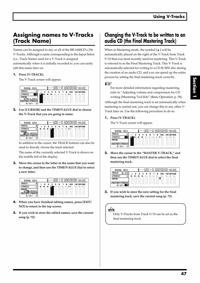
Using V-Tracks
Section 1
Assigning names to V-Tracks (Track Name) Names can be assigned to any or all of the BR-1600CD’s 256 V-Tracks. Although a name corresponding to the Input Select (i.e., Track Name) used for a V-Track is assigned automatically when it is initially recorded to, you can easily edit this name later on.
1. Press [V-TRACK].
The V-Track screen will appear.fig.11-01d
2. Use [CURSOR] and the TIME/VALUE dial to choose the V-Track that you are going to name.
fig.11-05d
In addition to the cursor, the TRACK buttons can also be used to directly choose the track selected.
The name of the currently selected V-Track is shown on the middle left of the display.
3. Move the cursor to the letter in the name that you want to change, and then use the TIME/VALUE dial to select a new letter.
fig.11-06d
4. When you have finished editing names, press [EXIT/NO] to return to the top screen.
5. If you wish to store the edited names, save the current song (p. 72).
Changing the V-Track to be written to an audio CD (the Final Mastering Track) When in Mastering mode, the symbol [ ] will be automatically placed on the right of the V-Track from Track 9/10 that was most recently used for mastering. This V-Track is referred to as the Final Mastering Track. This V-Track is automatically selected for writing to a CD-R/RW disc during the creation of an audio CD, and you can speed up the entire process by setting the final mastering track correctly.
For more detailed information regarding mastering, refer to “Adjusting volume and compression for CD writing (Mastering Tool Kit)” (Basic Operation; p. 58).
Although the final mastering track is set automatically when mastering is carried out, you can change this to any other V-Track later on. Use the following procedure to do so.
1. Press [V-TRACK].
The V-Track screen will appear.fig.11-07d
2. Move the cursor to the “MASTER V-TRACK,” and then use the TIME/VALUE dial to select the final mastering track.
fig.11-08d
3. If you wish to store the new setting for the final mastering track, save the current song (p. 72).
Only V-Tracks from Track 9/10 can be set as the final mastering track.
47
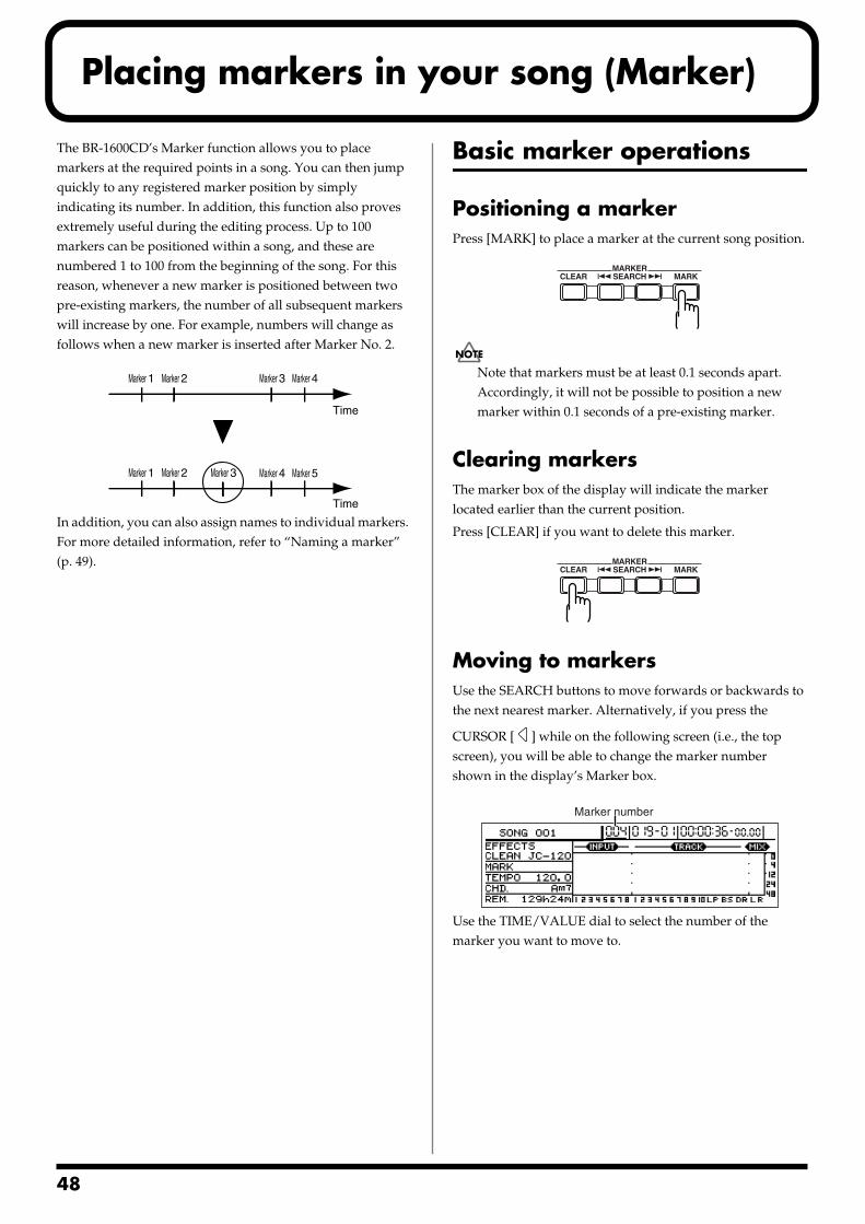
4
Placing markers in your song (Marker)
The BR-1600CD’s Marker function allows you to place markers at the required points in a song. You can then jump quickly to any registered marker position by simply indicating its number. In addition, this function also proves extremely useful during the editing process. Up to 100 markers can be positioned within a song, and these are numbered 1 to 100 from the beginning of the song. For this reason, whenever a new marker is positioned between two pre-existing markers, the number of all subsequent markers will increase by one. For example, numbers will change as follows when a new marker is inserted after Marker No. 2.fig.12-01
In addition, you can also assign names to individual markers. For more detailed information, refer to “Naming a marker” (p. 49).
Basic marker operations
Positioning a markerPress [MARK] to place a marker at the current song position.fig.12-02
Note that markers must be at least 0.1 seconds apart. Accordingly, it will not be possible to position a new marker within 0.1 seconds of a pre-existing marker.
Clearing markersThe marker box of the display will indicate the marker located earlier than the current position.
Press [CLEAR] if you want to delete this marker.fig.12-03
Moving to markersUse the SEARCH buttons to move forwards or backwards to the next nearest marker. Alternatively, if you press the
CURSOR [ ] while on the following screen (i.e., the top screen), you will be able to change the marker number shown in the display’s Marker box.fig.12-04
Use the TIME/VALUE dial to select the number of the marker you want to move to.
Time
Time
Marker 1 Marker 2
Marker 1 Marker 2 Marker 3
Marker 3 Marker 4
Marker 4 Marker 5
Marker number
8
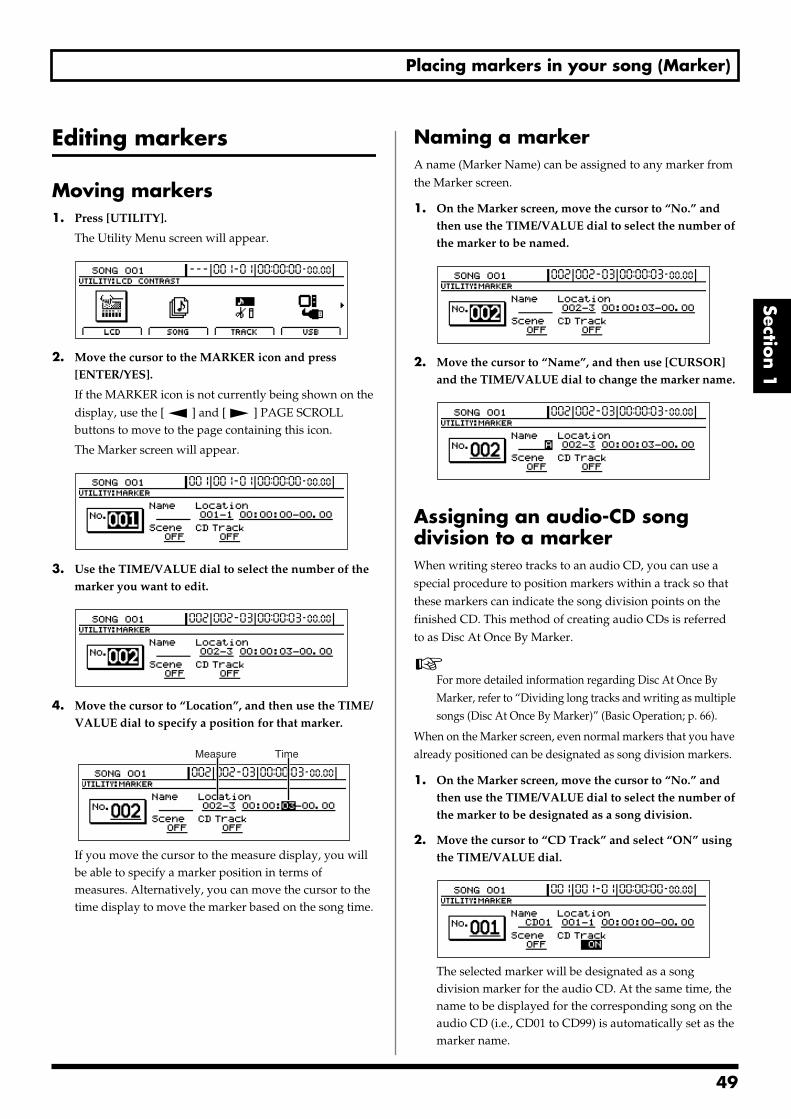
Placing markers in your song (Marker)
Section 1
Editing markers
Moving markers1. Press [UTILITY].
The Utility Menu screen will appear.fig.12-12d
2. Move the cursor to the MARKER icon and press [ENTER/YES].
If the MARKER icon is not currently being shown on the display, use the [ ] and [ ] PAGE SCROLL buttons to move to the page containing this icon.
The Marker screen will appear.fig.12-05d
3. Use the TIME/VALUE dial to select the number of the marker you want to edit.
fig.12-06d
4. Move the cursor to “Location”, and then use the TIME/VALUE dial to specify a position for that marker.
fig.12-07d
If you move the cursor to the measure display, you will be able to specify a marker position in terms of measures. Alternatively, you can move the cursor to the time display to move the marker based on the song time.
Naming a markerA name (Marker Name) can be assigned to any marker from the Marker screen.
1. On the Marker screen, move the cursor to “No.” and then use the TIME/VALUE dial to select the number of the marker to be named.
fig.12-08d
2. Move the cursor to “Name”, and then use [CURSOR] and the TIME/VALUE dial to change the marker name.
fig.12-09d
Assigning an audio-CD song division to a markerWhen writing stereo tracks to an audio CD, you can use a special procedure to position markers within a track so that these markers can indicate the song division points on the finished CD. This method of creating audio CDs is referred to as Disc At Once By Marker.
For more detailed information regarding Disc At Once By Marker, refer to “Dividing long tracks and writing as multiple songs (Disc At Once By Marker)” (Basic Operation; p. 66).
When on the Marker screen, even normal markers that you have already positioned can be designated as song division markers.
1. On the Marker screen, move the cursor to “No.” and then use the TIME/VALUE dial to select the number of the marker to be designated as a song division.
2. Move the cursor to “CD Track” and select “ON” using the TIME/VALUE dial.
fig.12-10d
The selected marker will be designated as a song division marker for the audio CD. At the same time, the name to be displayed for the corresponding song on the audio CD (i.e., CD01 to CD99) is automatically set as the marker name.
Measure Time
49
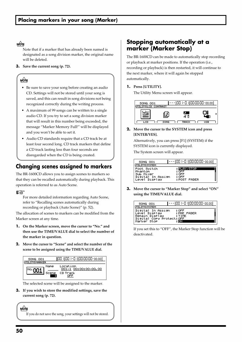
Placing markers in your song (Marker)
Note that if a marker that has already been named is designated as a song division marker, the original name will be deleted.
3. Save the current song (p. 72).
Changing scenes assigned to markersThe BR-1600CD allows you to assign scenes to markers so that they can be recalled automatically during playback. This operation is referred to as Auto Scene.
For more detailed information regarding Auto Scene, refer to “Recalling scenes automatically during recording or playback (Auto Scene)” (p. 52).
The allocation of scenes to markers can be modified from the Marker screen at any time.
1. On the Marker screen, move the cursor to “No.” and then use the TIME/VALUE dial to select the number of the marker in question.
2. Move the cursor to “Scene” and select the number of the scene to be assigned using the TIME/VALUE dial.
fig.12-11d
The selected scene will be assigned to the marker.
3. If you wish to store the modified settings, save the current song (p. 72).
Stopping automatically at a marker (Marker Stop) The BR-1600CD can be made to automatically stop recording or playback at marker positions. If the operation (i.e., recording or playback) is then restarted, it will continue to the next marker, where it will again be stopped automatically.
1. Press [UTILITY].
The Utility Menu screen will appear.fig.12-12d
2. Move the cursor to the SYSTEM icon and press [ENTER/YES].
Alternatively, you can press [F1] (SYSTEM) if the SYSTEM icon is currently displayed.
The System screen will appear.fig.10-03d
3. Move the cursor to “Marker Stop” and select “ON” using the TIME/VALUE dial.
fig.12-14d
If you set this to “OFF”, the Marker Stop function will be deactivated.
• Be sure to save your song before creating an audio CD. Settings will not be stored until your song is saved, and this can result in song divisions not being recognized correctly during the writing process.
• A maximum of 99 songs can be written to a single audio CD. If you try to set a song division marker that will result in this number being exceeded, the message “Marker Memory Full!” will be displayed and you won’t be able to set it.
• Audio CD standards require that a CD track be at least four second long. CD track markers that define a CD track lasting less than four seconds are disregarded when the CD is being created.
If you do not save the song, your settings will not be stored.
50

Registering and recalling mixer settings (Scene)
Section 1
The BR-1600CD allows you to register up to 100 batches of mixer and effect settings per song. Each of these batches of settings is referred to as a Scene, and they can be quickly and easily recalled whenever needed.For example, if you wish to compare different mix balances during mixdown, it is convenience to register each of the different mixer setting as a scene.In addition, you can also assign scenes to markers (p. 48) to have them recalled automatically during recording or playback, and this function is referred to as Auto Scene.
Registering, recalling, and deleting scenes1. Press [UTILITY].
The Utility Menu screen will appear.fig.12-12d
2. Move the cursor to the SCENE icon and press [ENTER/YES].
Alternatively, you can press [F3] (SCENE) if the SCENE icon is currently displayed.The Scene screen will appear.
fig.13-02d
3. Use the TIME/VALUE dial to select the number of the scene to be registered, recalled, or deleted.
fig.13-03d
If you select the number of a scene that has already been registered, an asterisk (*) will be displayed before the number to inform you of this fact.
4. Register, recall, or delete a scene.
To recall:
Press [F4] (CALL).
To register:
Press [F3] (SAVE).
An asterisk (*) indicates that a scene has already been registered. If you select such a scene, it will be overwritten using the current settings.
To delete:
Press [F2] (DELETE).
The asterisk (*) indicating a registered scene will disappear to show that the scene is no longer registered.
5. Press [EXIT/NO] several times to return to the top screen.
6. If you wish to store the scene settings, save the current song (p. 72).
Recalling a scene without changing track volumes When you recall a scene, the track volumes change to the levels stored in that scene, but the positions of the faders remain the same. As a result, fader positions and actual volumes will no longer match. However, the following procedure can be used in situations where you want to recall a scene without changing the track volumes from those matching the current fader positions.
1. Move to the Scene screen.
2. Move the cursor to “Track Level” and select “FADER” using the TIME/VALUE dial.
fig.13-04d
Track LevelThis setting determines how track volumes will be treated when a scene is recalled.
SCENE:
When a scene is recalled, the track volumes will change to the levels stored in that scene. As a result, it is quite possible that the front panel’s fader positions will no longer match the actual track volumes.
FADER:
Even if a scene is recalled, the track volumes will stay at the levels matching the positions of the front panel’s faders.
3. Press [EXIT/NO] several times to return to the top screen.
4. If you wish to store the modified settings, save the current song (p. 72).
If you do not save the song, your settings will not be stored.
51
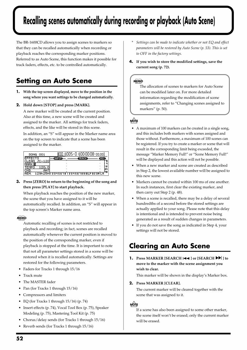
5
Recalling scenes automatically during recording or playback (Auto Scene)
The BR-1600CD allows you to assign scenes to markers so that they can be recalled automatically when recording or playback reaches the corresponding marker positions. Referred to as Auto Scene, this function makes it possible for track faders, effects, etc. to be controlled automatically.
Setting an Auto Scene1. With the top screen displayed, move to the position in the
song where you want settings to be changed automatically.
2. Hold down [STOP] and press [MARK].
A new marker will be created at the current position. Also at this time, a new scene will be created and assigned to the marker. All settings for track faders, effects, and the like will be stored in this scene.
In addition, an “S” will appear in the Marker name area on the top screen to indicate that a scene has been assigned to the marker.
fig.13-05
3. Press [ZERO] to return to the beginning of the song and then press [PLAY] to start playback.
When playback reaches the position of the new marker, the scene that you have assigned to it will be automatically recalled. In addition, an “S” will appear in the top screen’s Marker name area.
Automatic recalling of scenes is not restricted to playback and recording; in fact, scenes are recalled automatically whenever the current position is moved to the position of the corresponding marker, even if playback is stopped at the time. It is important to note that not all parameter settings stored in a scene will be restored when it is recalled automatically. Settings are restored for the following parameters.
• Faders for Tracks 1 through 15/16
• Track mute
• The MASTER fader
• Pan (for Tracks 1 through 15/16)
• Compressors and limiters
• EQ (for Tracks 1 through 15/16) (p. 74)
• Insert effects (p. 74), Vocal Tool Box (p. 75), Speaker Modeling (p. 75), Mastering Tool Kit (p. 75)
• Chorus/delay sends (for Tracks 1 through 15/16)
• Reverb sends (for Tracks 1 through 15/16)
* Settings can be made to indicate whether or not EQ and effect
parameters will be restored by Auto Scene (p. 53). This is set
to OFF in the factory settings.
4. If you wish to store the modified settings, save the current song (p. 72).
• A maximum of 100 markers can be created in a single song, and this includes both markers with scenes assigned and those without. Furthermore, a maximum of 100 scenes can be registered. If you try to create a marker or scene that will result in the corresponding limit being exceeded, the message “Marker Memory Full!” or “Scene Memory Full!” will be displayed and this action will not be possible.
• When a new marker and scene are created as described in Step 2, the lowest available number will be assigned to this new scene.
• Markers cannot be created within 100 ms of one another. In such instances, first clear the existing marker, and then carry out Step 2 (p. 48).
• When a scene is recalled, there may be a delay of several hundredths of a second before the stored settings are actually applied to your song. Please note that this delay is intentional and is intended to prevent noise being generated as a result of sudden changes in parameters.
• If you do not save the song as indicated in Step 4, your settings will not be stored.
Clearing an Auto Scene
1. Press MARKER [SEARCH ] or [SEARCH ] to move to the marker with the scene assignment you wish to clear.
This marker will be shown in the display’s Marker box.
2. Press MARKER [CLEAR].
The current marker will be cleared together with the scene that was assigned to it.
If a scene has also been assigned to some other marker, the scene itself won’t be erased; only the current marker will be erased.
The allocation of scenes to markers for Auto Scene can be modified later on. For more detailed information regarding the modification of scene assignments, refer to “Changing scenes assigned to markers” (p. 50).
2
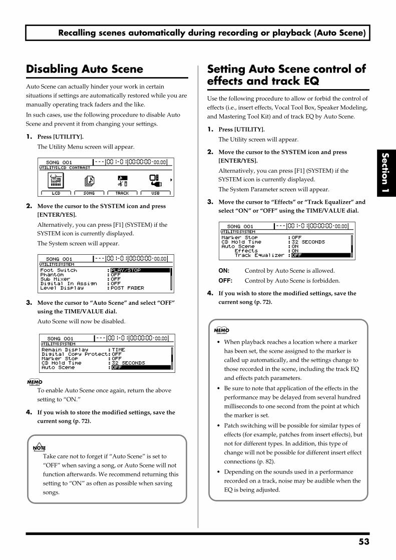
Recalling scenes automatically during recording or playback (Auto Scene)
Section 1
Disabling Auto SceneAuto Scene can actually hinder your work in certain situations if settings are automatically restored while you are manually operating track faders and the like.
In such cases, use the following procedure to disable Auto Scene and prevent it from changing your settings.
1. Press [UTILITY].
The Utility Menu screen will appear.fig.12-12d
2. Move the cursor to the SYSTEM icon and press [ENTER/YES].
Alternatively, you can press [F1] (SYSTEM) if the SYSTEM icon is currently displayed.
The System screen will appear.fig.10-03d
3. Move the cursor to “Auto Scene” and select “OFF” using the TIME/VALUE dial.
Auto Scene will now be disabled.fig.13-07d
To enable Auto Scene once again, return the above setting to “ON.”
4. If you wish to store the modified settings, save the current song (p. 72).
Setting Auto Scene control of effects and track EQUse the following procedure to allow or forbid the control of effects (i.e., insert effects, Vocal Tool Box, Speaker Modeling, and Mastering Tool Kit) and of track EQ by Auto Scene.
1. Press [UTILITY].
The Utility screen will appear.
2. Move the cursor to the SYSTEM icon and press [ENTER/YES].
Alternatively, you can press [F1] (SYSTEM) if the SYSTEM icon is currently displayed.
The System Parameter screen will appear.
3. Move the cursor to “Effects” or “Track Equalizer” and select “ON” or “OFF” using the TIME/VALUE dial.
fig.10-03d
ON: Control by Auto Scene is allowed.
OFF: Control by Auto Scene is forbidden.
4. If you wish to store the modified settings, save the current song (p. 72).
Take care not to forget if “Auto Scene” is set to “OFF” when saving a song, or Auto Scene will not function afterwards. We recommend returning this setting to “ON” as often as possible when saving songs.
• When playback reaches a location where a marker has been set, the scene assigned to the marker is called up automatically, and the settings change to those recorded in the scene, including the track EQ and effects patch parameters.
• Be sure to note that application of the effects in the performance may be delayed from several hundred milliseconds to one second from the point at which the marker is set.
• Patch switching will be possible for similar types of effects (for example, patches from insert effects), but not for different types. In addition, this type of change will not be possible for different insert effect connections (p. 82).
• Depending on the sounds used in a performance recorded on a track, noise may be audible when the EQ is being adjusted.
53
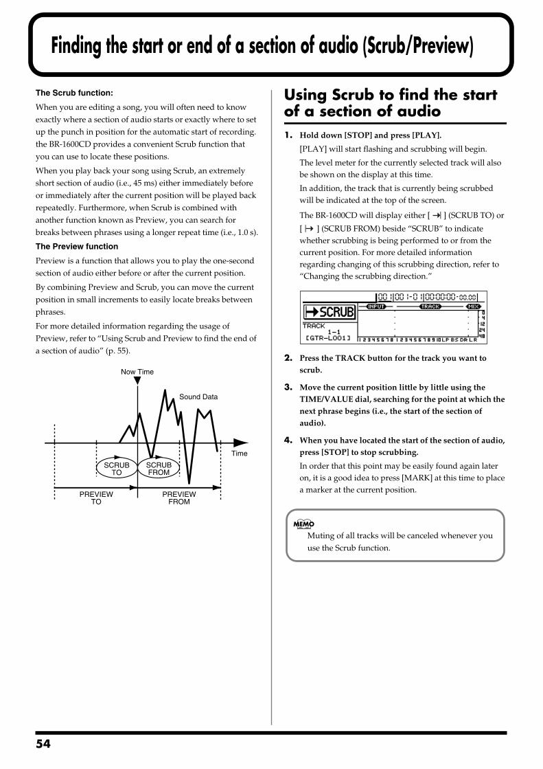
5
Finding the start or end of a section of audio (Scrub/Preview)
The Scrub function:
When you are editing a song, you will often need to know exactly where a section of audio starts or exactly where to set up the punch in position for the automatic start of recording. the BR-1600CD provides a convenient Scrub function that you can use to locate these positions.
When you play back your song using Scrub, an extremely short section of audio (i.e., 45 ms) either immediately before or immediately after the current position will be played back repeatedly. Furthermore, when Scrub is combined with another function known as Preview, you can search for breaks between phrases using a longer repeat time (i.e., 1.0 s).
The Preview function
Preview is a function that allows you to play the one-second section of audio either before or after the current position.
By combining Preview and Scrub, you can move the current position in small increments to easily locate breaks between phrases.
For more detailed information regarding the usage of Preview, refer to “Using Scrub and Preview to find the end of a section of audio” (p. 55).
Using Scrub to find the start of a section of audio1. Hold down [STOP] and press [PLAY].
[PLAY] will start flashing and scrubbing will begin.
The level meter for the currently selected track will also be shown on the display at this time.
In addition, the track that is currently being scrubbed will be indicated at the top of the screen.
The BR-1600CD will display either [ ] (SCRUB TO) or
[ ] (SCRUB FROM) beside “SCRUB” to indicate whether scrubbing is being performed to or from the current position. For more detailed information regarding changing of this scrubbing direction, refer to “Changing the scrubbing direction.”
fig.14-01d
2. Press the TRACK button for the track you want to scrub.
3. Move the current position little by little using the TIME/VALUE dial, searching for the point at which the next phrase begins (i.e., the start of the section of audio).
4. When you have located the start of the section of audio, press [STOP] to stop scrubbing.
In order that this point may be easily found again later on, it is a good idea to press [MARK] at this time to place a marker at the current position.
SCRUBTO
Time
Now Time
PREVIEWTO
PREVIEWFROM
Sound Data
SCRUBFROM
Muting of all tracks will be canceled whenever you use the Scrub function.
4
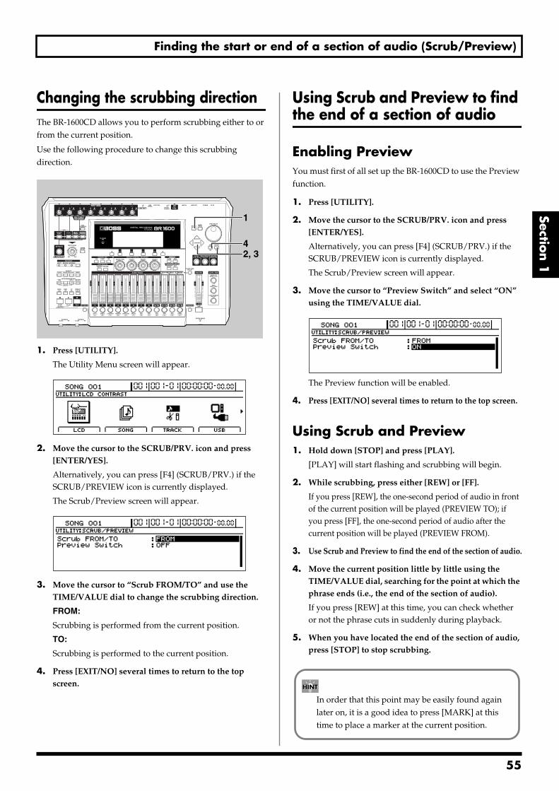
Finding the start or end of a section of audio (Scrub/Preview)
Section 1
Changing the scrubbing directionThe BR-1600CD allows you to perform scrubbing either to or from the current position.
Use the following procedure to change this scrubbing direction.fig.14-02
1. Press [UTILITY].
The Utility Menu screen will appear.fig.12-50d
2. Move the cursor to the SCRUB/PRV. icon and press [ENTER/YES].
Alternatively, you can press [F4] (SCRUB/PRV.) if the SCRUB/PREVIEW icon is currently displayed.
The Scrub/Preview screen will appear.fig.14-003d
3. Move the cursor to “Scrub FROM/TO” and use the TIME/VALUE dial to change the scrubbing direction.
FROM:
Scrubbing is performed from the current position.
TO:
Scrubbing is performed to the current position.
4. Press [EXIT/NO] several times to return to the top screen.
Using Scrub and Preview to find the end of a section of audio
Enabling PreviewYou must first of all set up the BR-1600CD to use the Preview function.
1. Press [UTILITY].
2. Move the cursor to the SCRUB/PRV. icon and press [ENTER/YES].
Alternatively, you can press [F4] (SCRUB/PRV.) if the SCRUB/PREVIEW icon is currently displayed.
The Scrub/Preview screen will appear.
3. Move the cursor to “Preview Switch” and select “ON” using the TIME/VALUE dial.
fig.14-04d
The Preview function will be enabled.
4. Press [EXIT/NO] several times to return to the top screen.
Using Scrub and Preview1. Hold down [STOP] and press [PLAY].
[PLAY] will start flashing and scrubbing will begin.
2. While scrubbing, press either [REW] or [FF].
If you press [REW], the one-second period of audio in front of the current position will be played (PREVIEW TO); if you press [FF], the one-second period of audio after the current position will be played (PREVIEW FROM).
3. Use Scrub and Preview to find the end of the section of audio.
4. Move the current position little by little using the TIME/VALUE dial, searching for the point at which the phrase ends (i.e., the end of the section of audio).
If you press [REW] at this time, you can check whether or not the phrase cuts in suddenly during playback.
5. When you have located the end of the section of audio, press [STOP] to stop scrubbing.
2, 34
1
In order that this point may be easily found again later on, it is a good idea to press [MARK] at this time to place a marker at the current position.
55
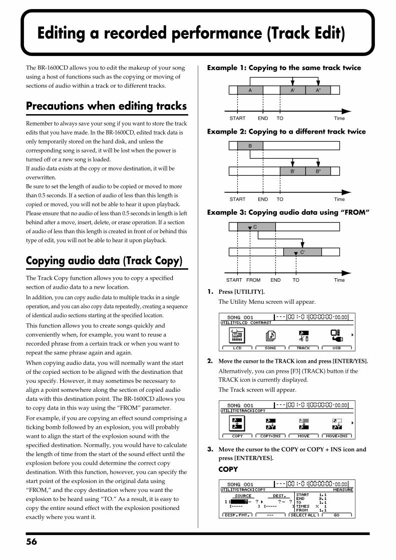
5
Editing a recorded performance (Track Edit)
The BR-1600CD allows you to edit the makeup of your song using a host of functions such as the copying or moving of sections of audio within a track or to different tracks.
Precautions when editing tracksRemember to always save your song if you want to store the track edits that you have made. In the BR-1600CD, edited track data is only temporarily stored on the hard disk, and unless the corresponding song is saved, it will be lost when the power is turned off or a new song is loaded.If audio data exists at the copy or move destination, it will be overwritten.Be sure to set the length of audio to be copied or moved to more than 0.5 seconds. If a section of audio of less than this length is copied or moved, you will not be able to hear it upon playback.Please ensure that no audio of less than 0.5 seconds in length is left behind after a move, insert, delete, or erase operation. If a section of audio of less than this length is created in front of or behind this type of edit, you will not be able to hear it upon playback.
Copying audio data (Track Copy)The Track Copy function allows you to copy a specified section of audio data to a new location.
In addition, you can copy audio data to multiple tracks in a single operation, and you can also copy data repeatedly, creating a sequence of identical audio sections starting at the specified location.
This function allows you to create songs quickly and conveniently when, for example, you want to reuse a recorded phrase from a certain track or when you want to repeat the same phrase again and again.
When copying audio data, you will normally want the start of the copied section to be aligned with the destination that you specify. However, it may sometimes be necessary to align a point somewhere along the section of copied audio data with this destination point. The BR-1600CD allows you to copy data in this way using the “FROM” parameter.
For example, if you are copying an effect sound comprising a ticking bomb followed by an explosion, you will probably want to align the start of the explosion sound with the specified destination. Normally, you would have to calculate the length of time from the start of the sound effect until the explosion before you could determine the correct copy destination. With this function, however, you can specify the start point of the explosion in the original data using “FROM,” and the copy destination where you want the explosion to be heard using “TO.” As a result, it is easy to copy the entire sound effect with the explosion positioned exactly where you want it.
Example 1: Copying to the same track twicefig.15-01
Example 2: Copying to a different track twicefig.15-02
Example 3: Copying audio data using “FROM”fig.15-03
1. Press [UTILITY].
The Utility Menu screen will appear.fig.12-12d
2. Move the cursor to the TRACK icon and press [ENTER/YES].
Alternatively, you can press [F3] (TRACK) button if the TRACK icon is currently displayed.
The Track screen will appear.fig.15-05d
3. Move the cursor to the COPY or COPY + INS icon and press [ENTER/YES].
COPYfig.15-06d
A A' A"
START END TO Time
B
B' B"
START END TO Time
START END TO TimeFROM
C
C'
6
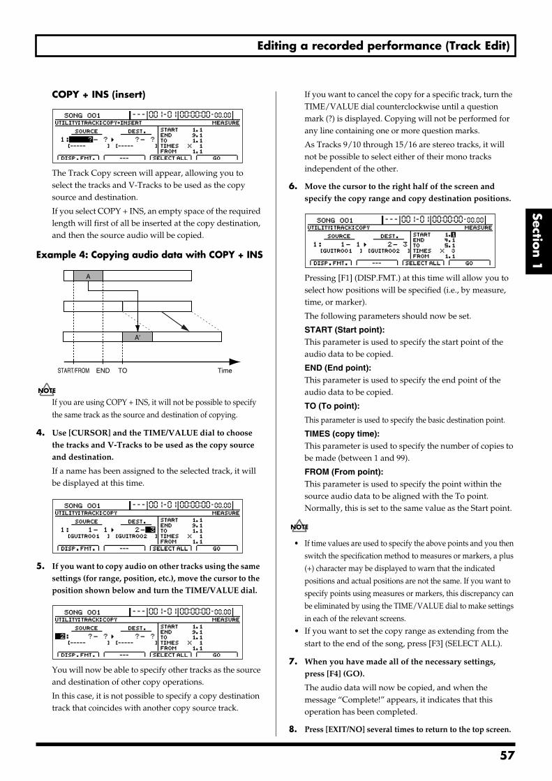
Editing a recorded performance (Track Edit)
Section 1
COPY + INS (insert)fig.15-07d
The Track Copy screen will appear, allowing you to select the tracks and V-Tracks to be used as the copy source and destination.
If you select COPY + INS, an empty space of the required length will first of all be inserted at the copy destination, and then the source audio will be copied.
Example 4: Copying audio data with COPY + INSfig.15-08
If you are using COPY + INS, it will not be possible to specify the same track as the source and destination of copying.
4. Use [CURSOR] and the TIME/VALUE dial to choose the tracks and V-Tracks to be used as the copy source and destination.
If a name has been assigned to the selected track, it will be displayed at this time.
fig.15-09d
5. If you want to copy audio on other tracks using the same settings (for range, position, etc.), move the cursor to the position shown below and turn the TIME/VALUE dial.
fig.15-20d
You will now be able to specify other tracks as the source and destination of other copy operations.
In this case, it is not possible to specify a copy destination track that coincides with another copy source track.
If you want to cancel the copy for a specific track, turn the TIME/VALUE dial counterclockwise until a question mark (?) is displayed. Copying will not be performed for any line containing one or more question marks.
As Tracks 9/10 through 15/16 are stereo tracks, it will not be possible to select either of their mono tracks independent of the other.
6. Move the cursor to the right half of the screen and specify the copy range and copy destination positions.
fig.15-21d
Pressing [F1] (DISP.FMT.) at this time will allow you to select how positions will be specified (i.e., by measure, time, or marker).
The following parameters should now be set.
START (Start point):This parameter is used to specify the start point of the audio data to be copied.
END (End point):This parameter is used to specify the end point of the audio data to be copied.
TO (To point):
This parameter is used to specify the basic destination point.
TIMES (copy time):This parameter is used to specify the number of copies to be made (between 1 and 99).
FROM (From point):This parameter is used to specify the point within the source audio data to be aligned with the To point. Normally, this is set to the same value as the Start point.
• If time values are used to specify the above points and you then switch the specification method to measures or markers, a plus (+) character may be displayed to warn that the indicated positions and actual positions are not the same. If you want to specify points using measures or markers, this discrepancy can be eliminated by using the TIME/VALUE dial to make settings in each of the relevant screens.
• If you want to set the copy range as extending from the start to the end of the song, press [F3] (SELECT ALL).
7. When you have made all of the necessary settings, press [F4] (GO).
The audio data will now be copied, and when the message “Complete!” appears, it indicates that this operation has been completed.
8. Press [EXIT/NO] several times to return to the top screen.
A
START/FROM END TO
A'
Time
57
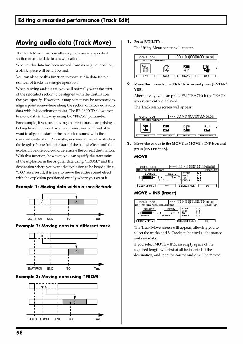
Editing a recorded performance (Track Edit)
Moving audio data (Track Move)The Track Move function allows you to move a specified section of audio data to a new location.
When audio data has been moved from its original position, a blank space will be left behind.
You can also use this function to move audio data from a number of tracks in a single operation.
When moving audio data, you will normally want the start of the relocated section to be aligned with the destination that you specify. However, it may sometimes be necessary to align a point somewhere along the section of relocated audio data with this destination point. The BR-1600CD allows you to move data in this way using the “FROM” parameter.
For example, if you are moving an effect sound comprising a ticking bomb followed by an explosion, you will probably want to align the start of the explosion sound with the specified destination. Normally, you would have to calculate the length of time from the start of the sound effect until the explosion before you could determine the correct destination. With this function, however, you can specify the start point of the explosion in the original data using “FROM,” and the destination where you want the explosion to be heard using “TO.” As a result, it is easy to move the entire sound effect with the explosion positioned exactly where you want it.
Example 1: Moving data within a specific trackfig.15-22
Example 2: Moving data to a different trackfig.15-23
Example 3: Moving data using “FROM”fig.15-24
1. Press [UTILITY].
The Utility Menu screen will appear.fig.12-12d
2. Move the cursor to the TRACK icon and press [ENTER/YES].
Alternatively, you can press [F3] (TRACK) if the TRACK icon is currently displayed.
The Track Menu screen will appear.fig.15-05d
3. Move the cursor to the MOVE or MOVE + INS icon and press [ENTER/YES].
MOVEfig.15-27d
MOVE + INS (insert)fig.15-28d
The Track Move screen will appear, allowing you to select the tracks and V-Tracks to be used as the source and destination.
If you select MOVE + INS, an empty space of the required length will first of all be inserted at the destination, and then the source audio will be moved.
A A
START/FROM END TO Time
B
B
START/FROM END TO Time
C
C
START END TO TimeFROM
58
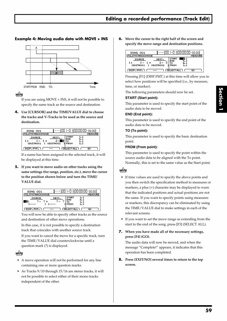
Editing a recorded performance (Track Edit)
Section 1
Example 4: Moving audio data with MOVE + INSfig.15-29
If you are using MOVE + INS, it will not be possible to specify the same track as the source and destination.
4. Use [CURSOR] and the TIME/VALUE dial to choose the tracks and V-Tracks to be used as the source and destination.
fig.15-30d
If a name has been assigned to the selected track, it will be displayed at this time.
5. If you want to move audio on other tracks using the same settings (for range, position, etc.), move the cursor to the position shown below and turn the TIME/VALUE dial.
fig.15-31d
You will now be able to specify other tracks as the source and destination of other move operations.
In this case, it is not possible to specify a destination track that coincides with another source track.
If you want to cancel the move for a specific track, turn the TIME/VALUE dial counterclockwise until a question mark (?) is displayed.
• A move operation will not be performed for any line containing one or more question marks.
• As Tracks 9/10 through 15/16 are stereo tracks, it will not be possible to select either of their mono tracks independent of the other.
6. Move the cursor to the right half of the screen and specify the move range and destination positions.
fig.15-32d
Pressing [F1] (DISP.FMT.) at this time will allow you to select how positions will be specified (i.e., by measure, time, or marker).
The following parameters should now be set.
START (Start point):
This parameter is used to specify the start point of the audio data to be moved.
END (End point):
This parameter is used to specify the end point of the audio data to be moved.
TO (To point):
This parameter is used to specify the basic destination point.
FROM (From point):
This parameter is used to specify the point within the source audio data to be aligned with the To point. Normally, this is set to the same value as the Start point.
• If time values are used to specify the above points and you then switch the specification method to measures or markers, a plus (+) character may be displayed to warn that the indicated positions and actual positions are not the same. If you want to specify points using measures or markers, this discrepancy can be eliminated by using the TIME/VALUE dial to make settings in each of the relevant screens.
• If you want to set the move range as extending from the start to the end of the song, press [F3] (SELECT ALL).
7. When you have made all of the necessary settings, press [F4] (GO).
The audio data will now be moved, and when the message “Complete!” appears, it indicates that this operation has been completed.
8. Press [EXIT/NO] several times to return to the top screen.
START/FROM END TO
A'A'
A
Time
59
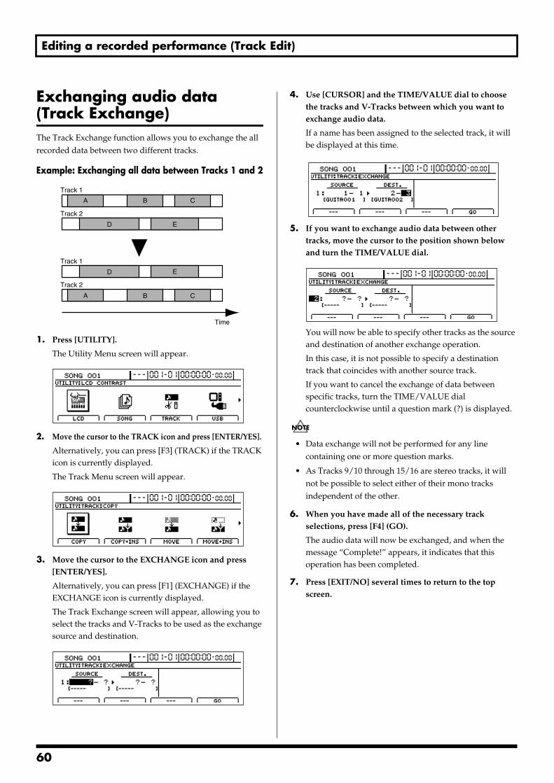
Editing a recorded performance (Track Edit)
Exchanging audio data (Track Exchange)The Track Exchange function allows you to exchange the all recorded data between two different tracks.
Example: Exchanging all data between Tracks 1 and 2fig.15-33
1. Press [UTILITY].
The Utility Menu screen will appear.fig.12-12d
2. Move the cursor to the TRACK icon and press [ENTER/YES].
Alternatively, you can press [F3] (TRACK) if the TRACK icon is currently displayed.
The Track Menu screen will appear.fig.15-05d
3. Move the cursor to the EXCHANGE icon and press [ENTER/YES].
Alternatively, you can press [F1] (EXCHANGE) if the EXCHANGE icon is currently displayed.
The Track Exchange screen will appear, allowing you to select the tracks and V-Tracks to be used as the exchange source and destination.
fig.15-36d
4. Use [CURSOR] and the TIME/VALUE dial to choose the tracks and V-Tracks between which you want to exchange audio data.
If a name has been assigned to the selected track, it will be displayed at this time.
fig.15-37d
5. If you want to exchange audio data between other tracks, move the cursor to the position shown below and turn the TIME/VALUE dial.
fig.15-38d
You will now be able to specify other tracks as the source and destination of another exchange operation.
In this case, it is not possible to specify a destination track that coincides with another source track.
If you want to cancel the exchange of data between specific tracks, turn the TIME/VALUE dial counterclockwise until a question mark (?) is displayed.
• Data exchange will not be performed for any line containing one or more question marks.
• As Tracks 9/10 through 15/16 are stereo tracks, it will not be possible to select either of their mono tracks independent of the other.
6. When you have made all of the necessary track selections, press [F4] (GO).
The audio data will now be exchanged, and when the message “Complete!” appears, it indicates that this operation has been completed.
7. Press [EXIT/NO] several times to return to the top screen.
Track 1
Track 2
Track 1
Track 2
A
A
B
B
C
C
D
D
E
E
Time
60
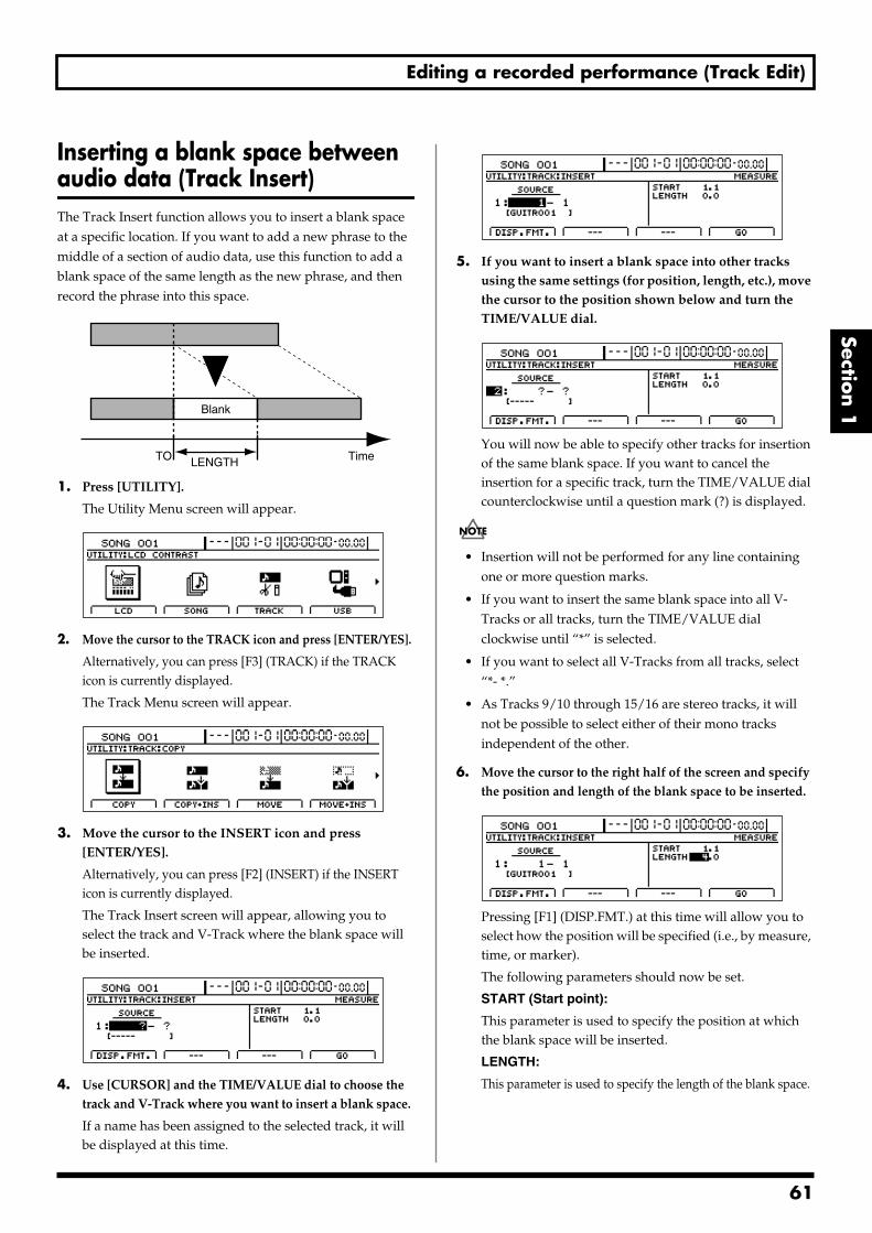
Editing a recorded performance (Track Edit)
Section 1
Inserting a blank space between audio data (Track Insert)The Track Insert function allows you to insert a blank space at a specific location. If you want to add a new phrase to the middle of a section of audio data, use this function to add a blank space of the same length as the new phrase, and then record the phrase into this space.fig.15-39
1. Press [UTILITY].
The Utility Menu screen will appear.fig.12-12d
2. Move the cursor to the TRACK icon and press [ENTER/YES].
Alternatively, you can press [F3] (TRACK) if the TRACK icon is currently displayed.
The Track Menu screen will appear.fig.15-05d
3. Move the cursor to the INSERT icon and press [ENTER/YES].
Alternatively, you can press [F2] (INSERT) if the INSERT icon is currently displayed.
The Track Insert screen will appear, allowing you to select the track and V-Track where the blank space will be inserted.
fig.15-42d
4. Use [CURSOR] and the TIME/VALUE dial to choose the track and V-Track where you want to insert a blank space.
If a name has been assigned to the selected track, it will be displayed at this time.
fig.15-43d
5. If you want to insert a blank space into other tracks using the same settings (for position, length, etc.), move the cursor to the position shown below and turn the TIME/VALUE dial.
fig.15-44d
You will now be able to specify other tracks for insertion of the same blank space. If you want to cancel the insertion for a specific track, turn the TIME/VALUE dial counterclockwise until a question mark (?) is displayed.
• Insertion will not be performed for any line containing one or more question marks.
• If you want to insert the same blank space into all V-Tracks or all tracks, turn the TIME/VALUE dial clockwise until “*” is selected.
• If you want to select all V-Tracks from all tracks, select “*- *.”
• As Tracks 9/10 through 15/16 are stereo tracks, it will not be possible to select either of their mono tracks independent of the other.
6. Move the cursor to the right half of the screen and specify the position and length of the blank space to be inserted.
fig.15-45d
Pressing [F1] (DISP.FMT.) at this time will allow you to select how the position will be specified (i.e., by measure, time, or marker).
The following parameters should now be set.
START (Start point):
This parameter is used to specify the position at which the blank space will be inserted.
LENGTH:
This parameter is used to specify the length of the blank space.
TimeTO
Blank
LENGTH
61
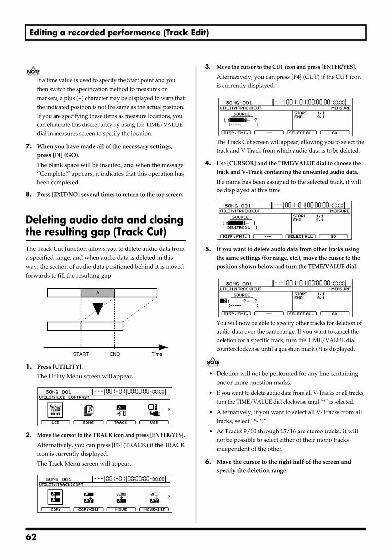
Editing a recorded performance (Track Edit)
If a time value is used to specify the Start point and you then switch the specification method to measures or markers, a plus (+) character may be displayed to warn that the indicated position is not the same as the actual position. If you are specifying these items as measure locations, you can eliminate this discrepancy by using the TIME/VALUE dial in measures screen to specify the location.
7. When you have made all of the necessary settings, press [F4] (GO).
The blank space will be inserted, and when the message “Complete!” appears, it indicates that this operation has been completed.
8. Press [EXIT/NO] several times to return to the top screen.
Deleting audio data and closing the resulting gap (Track Cut)The Track Cut function allows you to delete audio data from a specified range, and when audio data is deleted in this way, the section of audio data positioned behind it is moved forwards to fill the resulting gap. fig.15-46
1. Press [UTILITY].
The Utility Menu screen will appear.fig.12-12d
2. Move the cursor to the TRACK icon and press [ENTER/YES].
Alternatively, you can press [F3] (TRACK) if the TRACK icon is currently displayed.
The Track Menu screen will appear.fig.15-05d
3. Move the cursor to the CUT icon and press [ENTER/YES].
Alternatively, you can press [F4] (CUT) if the CUT icon is currently displayed.
fig.15-49d
The Track Cut screen will appear, allowing you to select the track and V-Track from which audio data is to be deleted.
4. Use [CURSOR] and the TIME/VALUE dial to choose the track and V-Track containing the unwanted audio data.
If a name has been assigned to the selected track, it will be displayed at this time.
fig.15-50d
5. If you want to delete audio data from other tracks using the same settings (for range, etc.), move the cursor to the position shown below and turn the TIME/VALUE dial.
fig.15-51d
You will now be able to specify other tracks for deletion of audio data over the same range. If you want to cancel the deletion for a specific track, turn the TIME/VALUE dial counterclockwise until a question mark (?) is displayed.
• Deletion will not be performed for any line containing one or more question marks.
• If you want to delete audio data from all V-Tracks or all tracks, turn the TIME/VALUE dial clockwise until “*” is selected.
• Alternatively, if you want to select all V-Tracks from all tracks, select “*- *.”
• As Tracks 9/10 through 15/16 are stereo tracks, it will not be possible to select either of their mono tracks independent of the other.
6. Move the cursor to the right half of the screen and specify the deletion range.
TimeSTART END
A
62
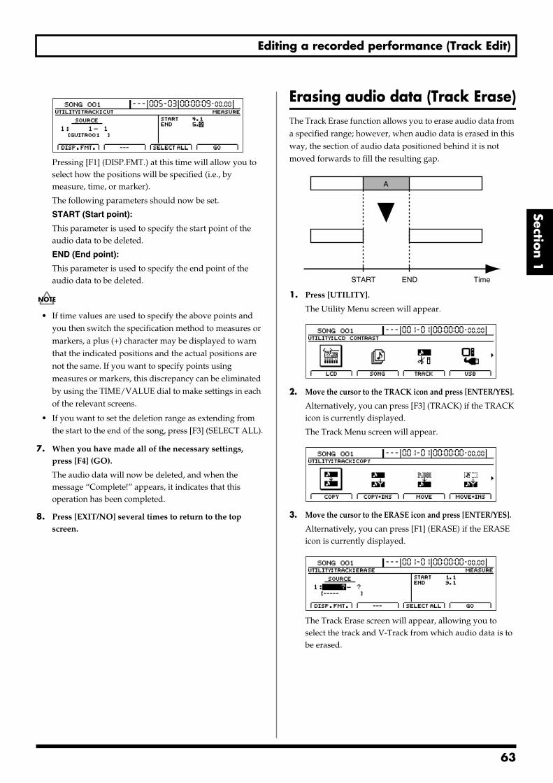
Editing a recorded performance (Track Edit)
Section 1
fig.15-52d
Pressing [F1] (DISP.FMT.) at this time will allow you to select how the positions will be specified (i.e., by measure, time, or marker).
The following parameters should now be set.
START (Start point):
This parameter is used to specify the start point of the audio data to be deleted.
END (End point):
This parameter is used to specify the end point of the audio data to be deleted.
• If time values are used to specify the above points and you then switch the specification method to measures or markers, a plus (+) character may be displayed to warn that the indicated positions and the actual positions are not the same. If you want to specify points using measures or markers, this discrepancy can be eliminated by using the TIME/VALUE dial to make settings in each of the relevant screens.
• If you want to set the deletion range as extending from the start to the end of the song, press [F3] (SELECT ALL).
7. When you have made all of the necessary settings, press [F4] (GO).
The audio data will now be deleted, and when the message “Complete!” appears, it indicates that this operation has been completed.
8. Press [EXIT/NO] several times to return to the top screen.
Erasing audio data (Track Erase)The Track Erase function allows you to erase audio data from a specified range; however, when audio data is erased in this way, the section of audio data positioned behind it is not moved forwards to fill the resulting gap.fig.15-53
1. Press [UTILITY].
The Utility Menu screen will appear.fig.12-12d
2. Move the cursor to the TRACK icon and press [ENTER/YES].
Alternatively, you can press [F3] (TRACK) if the TRACK icon is currently displayed.
The Track Menu screen will appear.fig.15-05d
3. Move the cursor to the ERASE icon and press [ENTER/YES].
Alternatively, you can press [F1] (ERASE) if the ERASE icon is currently displayed.
fig.15-56d
The Track Erase screen will appear, allowing you to select the track and V-Track from which audio data is to be erased.
START END Time
A
63
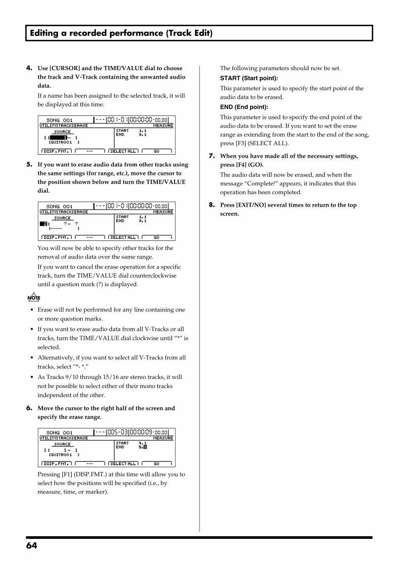
Editing a recorded performance (Track Edit)
4. Use [CURSOR] and the TIME/VALUE dial to choose the track and V-Track containing the unwanted audio data.
If a name has been assigned to the selected track, it will be displayed at this time.
fig.15-57d
5. If you want to erase audio data from other tracks using the same settings (for range, etc.), move the cursor to the position shown below and turn the TIME/VALUE dial.
fig.15-58d
You will now be able to specify other tracks for the removal of audio data over the same range.
If you want to cancel the erase operation for a specific track, turn the TIME/VALUE dial counterclockwise until a question mark (?) is displayed.
• Erase will not be performed for any line containing one or more question marks.
• If you want to erase audio data from all V-Tracks or all tracks, turn the TIME/VALUE dial clockwise until “*” is selected.
• Alternatively, if you want to select all V-Tracks from all tracks, select “*- *.”
• As Tracks 9/10 through 15/16 are stereo tracks, it will not be possible to select either of their mono tracks independent of the other.
6. Move the cursor to the right half of the screen and specify the erase range.
fig.15-59d
Pressing [F1] (DISP.FMT.) at this time will allow you to select how the positions will be specified (i.e., by measure, time, or marker).
The following parameters should now be set.
START (Start point):
This parameter is used to specify the start point of the audio data to be erased.
END (End point):
This parameter is used to specify the end point of the audio data to be erased. If you want to set the erase range as extending from the start to the end of the song, press [F3] (SELECT ALL).
7. When you have made all of the necessary settings, press [F4] (GO).
The audio data will now be erased, and when the message “Complete!” appears, it indicates that this operation has been completed.
8. Press [EXIT/NO] several times to return to the top screen.
64
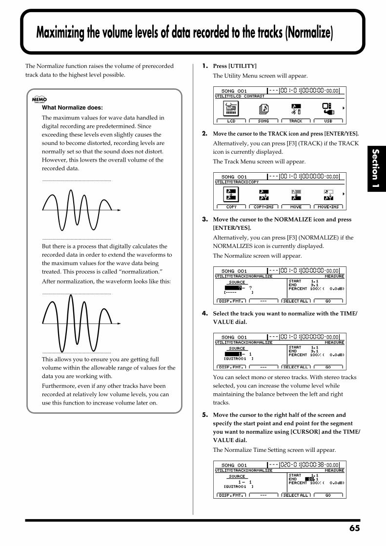
Maximizing the volume levels of data recorded to the tracks (Normalize)
Section 1
The Normalize function raises the volume of prerecorded track data to the highest level possible.
1. Press [UTILITY]
The Utility Menu screen will appear.fig.12-12d
2. Move the cursor to the TRACK icon and press [ENTER/YES].
Alternatively, you can press [F3] (TRACK) if the TRACK icon is currently displayed.
The Track Menu screen will appear.fig.15-05dI
3. Move the cursor to the NORMALIZE icon and press [ENTER/YES].
Alternatively, you can press [F3] (NORMALIZE) if the NORMALIZES icon is currently displayed.
The Normalize screen will appear.fig.15-72d
4. Select the track you want to normalize with the TIME/VALUE dial.
fig.15-72ad
You can select mono or stereo tracks. With stereo tracks selected, you can increase the volume level while maintaining the balance between the left and right tracks.
5. Move the cursor to the right half of the screen and specify the start point and end point for the segment you want to normalize using [CURSOR] and the TIME/VALUE dial.
The Normalize Time Setting screen will appear.fig.15-73d
What Normalize does:
The maximum values for wave data handled in digital recording are predetermined. Since exceeding these levels even slightly causes the sound to become distorted, recording levels are normally set so that the sound does not distort. However, this lowers the overall volume of the recorded data.
fig.sssss
But there is a process that digitally calculates the recorded data in order to extend the waveforms to the maximum values for the wave data being treated. This process is called “normalization.”
After normalization, the waveform looks like this:fig.sssss
This allows you to ensure you are getting full volume within the allowable range of values for the data you are working with.
Furthermore, even if any other tracks have been recorded at relatively low volume levels, you can use this function to increase volume later on.
65
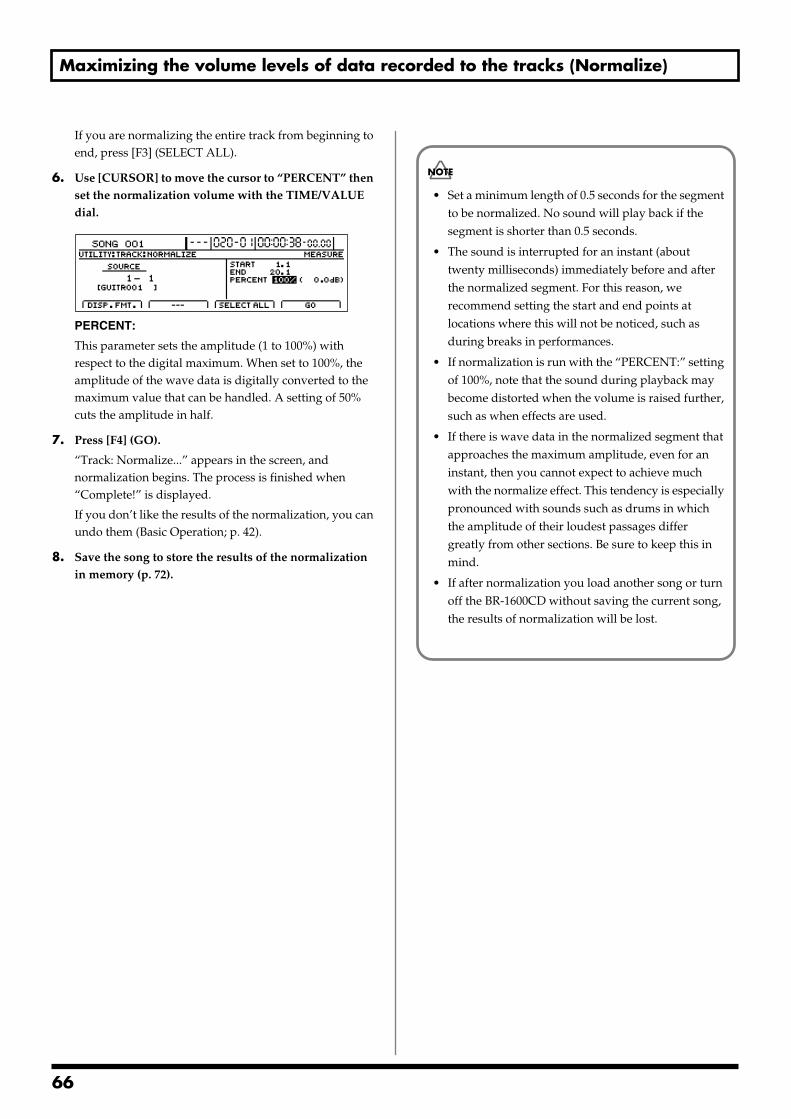
Maximizing the volume levels of data recorded to the tracks (Normalize)
If you are normalizing the entire track from beginning to end, press [F3] (SELECT ALL).
6. Use [CURSOR] to move the cursor to “PERCENT” then set the normalization volume with the TIME/VALUE dial.
fig.15-74d
PERCENT:
This parameter sets the amplitude (1 to 100%) with respect to the digital maximum. When set to 100%, the amplitude of the wave data is digitally converted to the maximum value that can be handled. A setting of 50% cuts the amplitude in half.
7. Press [F4] (GO).
“Track: Normalize...” appears in the screen, and normalization begins. The process is finished when “Complete!” is displayed.
If you don’t like the results of the normalization, you can undo them (Basic Operation; p. 42).
8. Save the song to store the results of the normalization in memory (p. 72).
• Set a minimum length of 0.5 seconds for the segment to be normalized. No sound will play back if the segment is shorter than 0.5 seconds.
• The sound is interrupted for an instant (about twenty milliseconds) immediately before and after the normalized segment. For this reason, we recommend setting the start and end points at locations where this will not be noticed, such as during breaks in performances.
• If normalization is run with the “PERCENT:” setting of 100%, note that the sound during playback may become distorted when the volume is raised further, such as when effects are used.
• If there is wave data in the normalized segment that approaches the maximum amplitude, even for an instant, then you cannot expect to achieve much with the normalize effect. This tendency is especially pronounced with sounds such as drums in which the amplitude of their loudest passages differ greatly from other sections. Be sure to keep this in mind.
• If after normalization you load another song or turn off the BR-1600CD without saving the current song, the results of normalization will be lost.
66
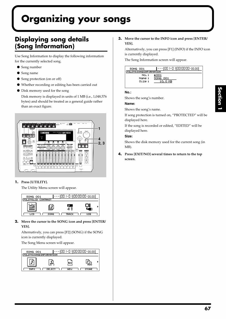
Organizing your songs
Section 1
Displaying song details (Song Information)Use Song Information to display the following information for the currently selected song.
Song number
Song name
Song protection (on or off)
Whether recording or editing has been carried out
Disk memory used for the song
Disk memory is displayed in units of 1 MB (i.e., 1,048,576 bytes) and should be treated as a general guide rather than an exact figure.
fig.16-01
1. Press [UTILITY].
The Utility Menu screen will appear.fig.12-12d
2. Move the cursor to the SONG icon and press [ENTER/YES].
Alternatively, you can press [F2] (SONG) if the SONG icon is currently displayed.
The Song Menu screen will appear.fig.16-03d
3. Move the cursor to the INFO icon and press [ENTER/YES].
Alternatively, you can press [F1] (INFO) if the INFO icon is currently displayed.
The Song Information screen will appear.fig.16-04d
No.:
Shows the song’s number.
Name:
Shows the song’s name.
If song protection is turned on, “PROTECTED” will be displayed here.
If the song is recorded or edited, “EDITED” will be displayed here.
Size:
Shows the disk memory used for the current song (in MB).
4. Press [EXIT/NO] several times to return to the top screen.
2, 34
1
67
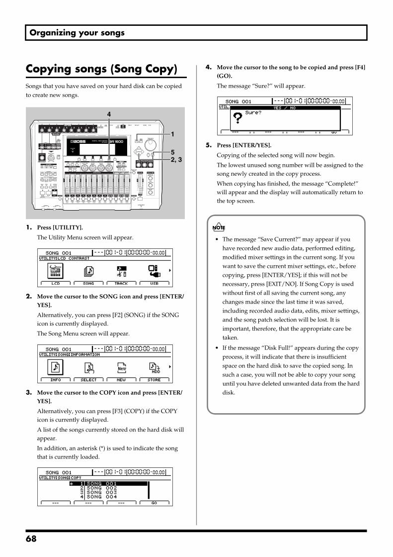
Organizing your songs
Copying songs (Song Copy)Songs that you have saved on your hard disk can be copied to create new songs.fig.16-05
1. Press [UTILITY].
The Utility Menu screen will appear.fig.12-12d
2. Move the cursor to the SONG icon and press [ENTER/YES].
Alternatively, you can press [F2] (SONG) if the SONG icon is currently displayed.
The Song Menu screen will appear.fig.16-03d
3. Move the cursor to the COPY icon and press [ENTER/YES].
Alternatively, you can press [F3] (COPY) if the COPY icon is currently displayed.
A list of the songs currently stored on the hard disk will appear.
In addition, an asterisk (*) is used to indicate the song that is currently loaded.
fig.16-08d
4. Move the cursor to the song to be copied and press [F4] (GO).
The message “Sure?” will appear.fig.16-09d
5. Press [ENTER/YES].
Copying of the selected song will now begin.
The lowest unused song number will be assigned to the song newly created in the copy process.
When copying has finished, the message “Complete!” will appear and the display will automatically return to the top screen.
2, 3
1
4
5
• The message “Save Current?” may appear if you have recorded new audio data, performed editing, modified mixer settings in the current song. If you want to save the current mixer settings, etc., before copying, press [ENTER/YES]; if this will not be necessary, press [EXIT/NO]. If Song Copy is used without first of all saving the current song, any changes made since the last time it was saved, including recorded audio data, edits, mixer settings, and the song patch selection will be lost. It is important, therefore, that the appropriate care be taken.
• If the message “Disk Full!” appears during the copy process, it will indicate that there is insufficient space on the hard disk to save the copied song. In such a case, you will not be able to copy your song until you have deleted unwanted data from the hard disk.
68
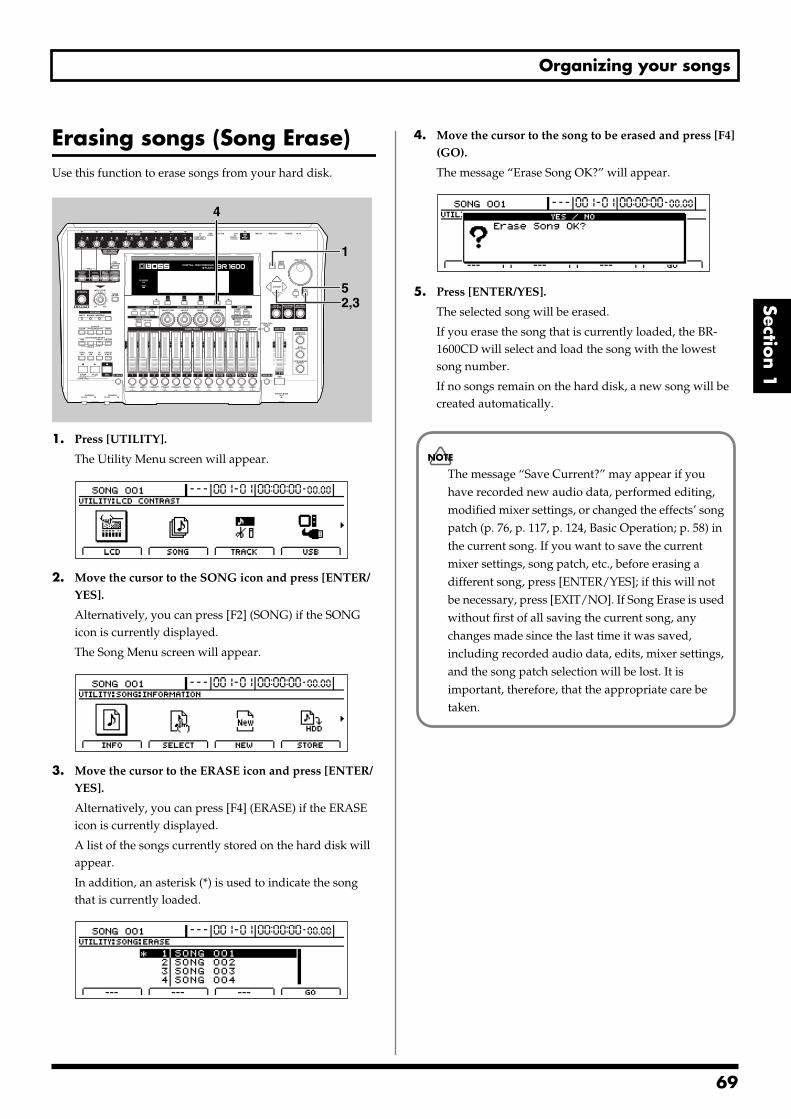
Organizing your songs
Section 1
Erasing songs (Song Erase)Use this function to erase songs from your hard disk.fig.16-05
1. Press [UTILITY].
The Utility Menu screen will appear.fig.12-12d
2. Move the cursor to the SONG icon and press [ENTER/YES].
Alternatively, you can press [F2] (SONG) if the SONG icon is currently displayed.
The Song Menu screen will appear.fig.16-03d
3. Move the cursor to the ERASE icon and press [ENTER/YES].
Alternatively, you can press [F4] (ERASE) if the ERASE icon is currently displayed.
A list of the songs currently stored on the hard disk will appear.
In addition, an asterisk (*) is used to indicate the song that is currently loaded.
fig.16-12d
4. Move the cursor to the song to be erased and press [F4] (GO).
The message “Erase Song OK?” will appear.fig.16-13d
5. Press [ENTER/YES].
The selected song will be erased.
If you erase the song that is currently loaded, the BR-1600CD will select and load the song with the lowest song number.
If no songs remain on the hard disk, a new song will be created automatically.
2,35
1
4
The message “Save Current?” may appear if you have recorded new audio data, performed editing, modified mixer settings, or changed the effects’ song patch (p. 76, p. 117, p. 124, Basic Operation; p. 58) in the current song. If you want to save the current mixer settings, song patch, etc., before erasing a different song, press [ENTER/YES]; if this will not be necessary, press [EXIT/NO]. If Song Erase is used without first of all saving the current song, any changes made since the last time it was saved, including recorded audio data, edits, mixer settings, and the song patch selection will be lost. It is important, therefore, that the appropriate care be taken.
69
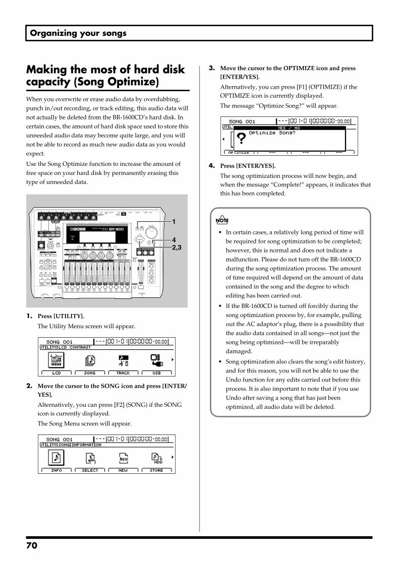
Organizing your songs
Making the most of hard disk capacity (Song Optimize)When you overwrite or erase audio data by overdubbing, punch in/out recording, or track editing, this audio data will not actually be deleted from the BR-1600CD’s hard disk. In certain cases, the amount of hard disk space used to store this unneeded audio data may become quite large, and you will not be able to record as much new audio data as you would expect.
Use the Song Optimize function to increase the amount of free space on your hard disk by permanently erasing this type of unneeded data.fig.16-05
1. Press [UTILITY].
The Utility Menu screen will appear.fig.12-12d
2. Move the cursor to the SONG icon and press [ENTER/YES].
Alternatively, you can press [F2] (SONG) if the SONG icon is currently displayed.
The Song Menu screen will appear.fig.16-03d
3. Move the cursor to the OPTIMIZE icon and press [ENTER/YES].
Alternatively, you can press [F1] (OPTIMIZE) if the OPTIMIZE icon is currently displayed.
The message “Optimize Song?” will appear.fig.16-16d
4. Press [ENTER/YES].
The song optimization process will now begin, and when the message “Complete!” appears, it indicates that this has been completed.
2,34
1
• In certain cases, a relatively long period of time will be required for song optimization to be completed; however, this is normal and does not indicate a malfunction. Please do not turn off the BR-1600CD during the song optimization process. The amount of time required will depend on the amount of data contained in the song and the degree to which editing has been carried out.
• If the BR-1600CD is turned off forcibly during the song optimization process by, for example, pulling out the AC adaptor’s plug, there is a possibility that the audio data contained in all songs—not just the song being optimized—will be irreparably damaged.
• Song optimization also clears the song’s edit history, and for this reason, you will not be able to use the Undo function for any edits carried out before this process. It is also important to note that if you use Undo after saving a song that has just been optimized, all audio data will be deleted.
70
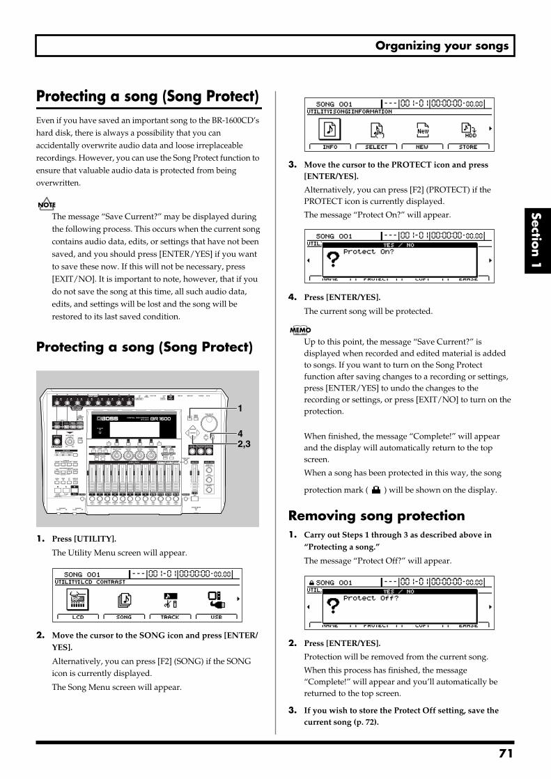
Organizing your songs
Section 1
Protecting a song (Song Protect)Even if you have saved an important song to the BR-1600CD’s hard disk, there is always a possibility that you can accidentally overwrite audio data and loose irreplaceable recordings. However, you can use the Song Protect function to ensure that valuable audio data is protected from being overwritten.
The message “Save Current?” may be displayed during the following process. This occurs when the current song contains audio data, edits, or settings that have not been saved, and you should press [ENTER/YES] if you want to save these now. If this will not be necessary, press [EXIT/NO]. It is important to note, however, that if you do not save the song at this time, all such audio data, edits, and settings will be lost and the song will be restored to its last saved condition.
Protecting a song (Song Protect)fig.16-05
1. Press [UTILITY].
The Utility Menu screen will appear.fig.12-12d
2. Move the cursor to the SONG icon and press [ENTER/YES].
Alternatively, you can press [F2] (SONG) if the SONG icon is currently displayed.
The Song Menu screen will appear.
fig.16-03d
3. Move the cursor to the PROTECT icon and press [ENTER/YES].
Alternatively, you can press [F2] (PROTECT) if the PROTECT icon is currently displayed.
The message “Protect On?” will appear.fig.16-20d
4. Press [ENTER/YES].
The current song will be protected.
Up to this point, the message “Save Current?” is displayed when recorded and edited material is added to songs. If you want to turn on the Song Protect function after saving changes to a recording or settings, press [ENTER/YES] to undo the changes to the recording or settings, or press [EXIT/NO] to turn on the protection.
When finished, the message “Complete!” will appear and the display will automatically return to the top screen.
When a song has been protected in this way, the song
protection mark ( ) will be shown on the display.
Removing song protection1. Carry out Steps 1 through 3 as described above in
“Protecting a song.”
The message “Protect Off?” will appear.fig.16-21d
2. Press [ENTER/YES].
Protection will be removed from the current song.
When this process has finished, the message “Complete!” will appear and you’ll automatically be returned to the top screen.
3. If you wish to store the Protect Off setting, save the current song (p. 72).
2,34
1
71
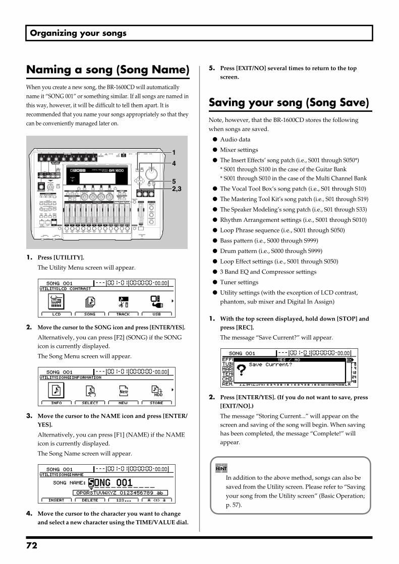
Organizing your songs
Naming a song (Song Name)When you create a new song, the BR-1600CD will automatically name it “SONG 001” or something similar. If all songs are named in this way, however, it will be difficult to tell them apart. It is recommended that you name your songs appropriately so that they can be conveniently managed later on.fig.16-05
1. Press [UTILITY].
The Utility Menu screen will appear.fig.12-12d
2. Move the cursor to the SONG icon and press [ENTER/YES].
Alternatively, you can press [F2] (SONG) if the SONG icon is currently displayed.
The Song Menu screen will appear.fig.16-03d
3. Move the cursor to the NAME icon and press [ENTER/YES].
Alternatively, you can press [F1] (NAME) if the NAME icon is currently displayed.
The Song Name screen will appear.fig.16-25d
4. Move the cursor to the character you want to change and select a new character using the TIME/VALUE dial.
5. Press [EXIT/NO] several times to return to the top screen.
Saving your song (Song Save)Note, however, that the BR-1600CD stores the following when songs are saved.
Audio data
Mixer settings
The Insert Effects’ song patch (i.e., S001 through S050*)* S001 through S100 in the case of the Guitar Bank* S001 through S010 in the case of the Multi Channel Bank
The Vocal Tool Box’s song patch (i.e., S01 through S10)
The Mastering Tool Kit’s song patch (i.e., S01 through S19)
The Speaker Modeling’s song patch (i.e., S01 through S33)
Rhythm Arrangement settings (i.e., S001 through S010)
Loop Phrase sequence (i.e., S001 through S050)
Bass pattern (i.e., S000 through S999)
Drum pattern (i.e., S000 through S999)
Loop Effect settings (i.e., S001 through S050)
3 Band EQ and Compressor settings
Tuner settings
Utility settings (with the exception of LCD contrast, phantom, sub mixer and Digital In Assign)
1. With the top screen displayed, hold down [STOP] and press [REC].
The message “Save Current?” will appear.fig.16-30d
2. Press [ENTER/YES]. (If you do not want to save, press [EXIT/NO].)
The message “Storing Current...” will appear on the screen and saving of the song will begin. When saving has been completed, the message “Complete!” will appear.
2,35
4
1
In addition to the above method, songs can also be saved from the Utility screen. Please refer to “Saving your song from the Utility screen” (Basic Operation; p. 57).
72
Section 2 Using Effects
Section 2Using Effects
73
7
Makeup of BR-1600CD effects
The BR-1600CD contains the following types of effects.
Insert effects (p. 76)Insert effects are applied to input audio and are capable of changing the sound in a wide range of different ways. By changing the way an insert effect is connected, you can have it be applied not only to the input audio, but also to a track’s playback or to the Master output. Furthermore, a host of different insert effects can be chosen to match the instrument or input in question.
GUITAR/BASS effects:These effects are used with audio from guitars and bass guitars. In addition to COSM amp modeling and COSM overdrive for electric guitars, the BR-1600CD features acoustic guitar simulators, bass guitar simulators, and many other effects for a range of different purposes.
MIC effects:These effects are used with audio from solo vocal microphones. The BR-1600CD features COSM compressors, COSM microphone modeling, de-esser, and a variety of other MIC effects that will prove very useful when recording from microphones.
SIMUL effects:These effects are used to record a guitar track and a vocal track simultaneously. For this reason, they allow effects for electric guitar or acoustic guitar to be used at the same time as vocal effects.
In terms of guitar effects, you can make use of amplifier modeling, acoustic guitar simulators, acoustic processors, and many other algorithms.
And in terms of vocal effects, compressors, equalizers, noise suppressors, delay, and the like have been made available.
Note that when SIMUL effects are used, the guitar effect will be applied to the INPUT 1/MIC 1 audio source; the vocal effect, to the INPUT 2/MIC 2 audio source.
MULTI-CHANNEL effects:These effects are used independently and simultaneously on 8 input sources. In order to provide for situations where you are recording from a number of different microphones, the BR-1600CD features eight-channel equalizers, compressors and low-cut filters.
STEREO effects:As the name suggests, these effects are applied to stereo inputs. The STEREO bank features stereo compressors, Lo-Fi processor, ring modulators, and a range of other effects.
What is COSM (Composite Object Sound Modeling)?Technology that virtually reconstructs an actually existing structure or material using a different means is called “modeling” technology. COSM is proprietary Roland technology that creates new sounds by combining various sound modeling technologies.
Track-specific equalizers and compressors (p. 108)
These effects are applied to the playback from individual tracks so that sounds can be made more compatible with each other.
Compressors:This type of effect is used to suppress variations in volume. If the volume of a track fluctuates widely, you can make it more uniform using a compressor. In addition, when compressors are applied heavily, they can suppress the dynamic volume variations that are characteristic of musical instruments, thus allowing you to create distinctive new sounds.
Compressors can be used on either 1 through 8 tracks or 9/10 through 15/16 tracks.
Three-band equalizers:This type of effect is used to modify the tone of an audio signal. To do this, it separates the range of frequencies that make up a sound into low, mid, and high bands, allowing the volume of each of these bands to be adjusted independently. Three-band equalizers (or EQs) can be used on all tracks (i.e., 1 through 8 and 9/10 through 15/16). Note also that the EQs for Tracks 9/10 through 15/16 are stereo effects.
Loop effects (p. 112)Applied to playback from tracks and to input audio being monitored, loop effects are used to add a sense of spaciousness and depth. The following types of loop effects are available on the BR-1600CD.
Reverb:By adding reverberation to a sound, this effect imbues the sound with a sense of spaciousness and depth.
Chorus:A chorus effect copies the original (direct) sound, changes its pitch slightly, and then adds this back to the original to make it swell or feel more like a stereo sound.
4
Makeup of BR-1600CD effects
Section 2
Delay:A delay is a little bit like an echo. It can add a sense of spaciousness and depth to the sound. In addition, when this effect is applied to instruments that play melodies, it can make their performance sound smoother or can add an extra bounce to their rhythm.
Doubling:This effect sets up a tiny time deviation (or delay) between the left and right sides of a signal to give the sound a stereo feel.
Vocal Tool Box (p. 116)The Vocal Tool Box is used with the playback from tracks on which solo vocal performances have been recorded, and it allows you to correct variations in pitch and to add a backing chorus.
The following two effects can be selected from the Vocal Tool Box.
Pitch CorrectionThe pitch correction function allows you to correct the pitches of vocal performances recorded on a track in real time and in units of semitones.
Harmony SequenceThis effect adds a backing chorus to the playback of a vocal performance recorded on a track based on the chord sequence specified for your rhythm arrangement (p. 148).
If this effect is applied to a track not containing a solo vocal performance, it will not be possible to achieve the desired result.
Mastering Tool Kit (p. 129)The BR-1600CD’s Mastering Tool Kit is used during the creation of an audio CD to improve the quality of the finished songs by balancing volumes and compression levels. When commercially available CDs are originally created, data is written to them in such a way that the loudest point in each song is close to the maximum volume that can be recorded on the CD. A good balance among the volumes of different performances is the most important factor in allowing data to be written in this way. However, a special process known as Mastering is generally carried out to adjust the overall volume. The Mastering Tool Kit provided in the BR-1600CD allows you carry out this special processing simply and quickly.
A good balance of the volumes of different performances is the most important factor when creating audio CDs that sound loud and powerful. If performances have not been mixed and balanced well, no amount of processing using the Mastering Tool Kit will produce the desired effect.
Speaker Modeling (p. 127)This effect allows the acoustical characteristics of various types of monitor speakers to be modeled for playback.
In professional recording studios, recorded audio is played through various types and sizes of monitor speakers so that the sound from each can be compared, and this ensures that the final mix-down will sound good on any type of speaker. Even if you only use one set of monitor speakers with the BR-1600CD, the Speaker Modeling effect allows you to compare the sound of different speakers in the same way.
Supported combinations of effects
Loop effects can always be used together with any track's compressor or EQ. Of the insert effects, the Vocal Tool Box, the Mastering Tool Box, and Speaker Modeling, only one of them can be used at a time.
75
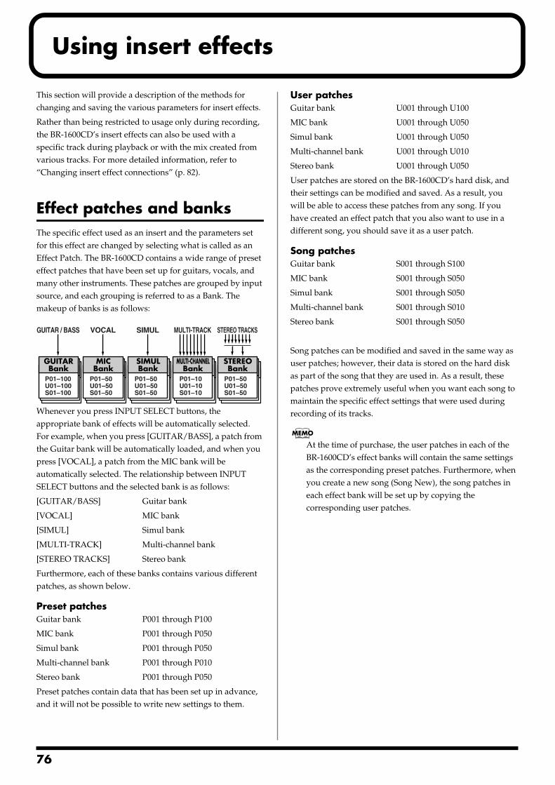
7
Using insert effects
This section will provide a description of the methods for changing and saving the various parameters for insert effects.
Rather than being restricted to usage only during recording, the BR-1600CD’s insert effects can also be used with a specific track during playback or with the mix created from various tracks. For more detailed information, refer to “Changing insert effect connections” (p. 82).
Effect patches and banksThe specific effect used as an insert and the parameters set for this effect are changed by selecting what is called as an Effect Patch. The BR-1600CD contains a wide range of preset effect patches that have been set up for guitars, vocals, and many other instruments. These patches are grouped by input source, and each grouping is referred to as a Bank. The makeup of banks is as follows:fig.31-00
Whenever you press INPUT SELECT buttons, the appropriate bank of effects will be automatically selected. For example, when you press [GUITAR/BASS], a patch from the Guitar bank will be automatically loaded, and when you press [VOCAL], a patch from the MIC bank will be automatically selected. The relationship between INPUT SELECT buttons and the selected bank is as follows:
[GUITAR/BASS] Guitar bank
[VOCAL] MIC bank
[SIMUL] Simul bank
[MULTI-TRACK] Multi-channel bank
[STEREO TRACKS] Stereo bank
Furthermore, each of these banks contains various different patches, as shown below.
Preset patchesGuitar bank P001 through P100
MIC bank P001 through P050
Simul bank P001 through P050
Multi-channel bank P001 through P010
Stereo bank P001 through P050
Preset patches contain data that has been set up in advance, and it will not be possible to write new settings to them.
User patchesGuitar bank U001 through U100
MIC bank U001 through U050
Simul bank U001 through U050
Multi-channel bank U001 through U010
Stereo bank U001 through U050
User patches are stored on the BR-1600CD’s hard disk, and their settings can be modified and saved. As a result, you will be able to access these patches from any song. If you have created an effect patch that you also want to use in a different song, you should save it as a user patch.
Song patchesGuitar bank S001 through S100
MIC bank S001 through S050
Simul bank S001 through S050
Multi-channel bank S001 through S010
Stereo bank S001 through S050
Song patches can be modified and saved in the same way as user patches; however, their data is stored on the hard disk as part of the song that they are used in. As a result, these patches prove extremely useful when you want each song to maintain the specific effect settings that were used during recording of its tracks.
At the time of purchase, the user patches in each of the BR-1600CD’s effect banks will contain the same settings as the corresponding preset patches. Furthermore, when you create a new song (Song New), the song patches in each effect bank will be set up by copying the corresponding user patches.
GUITARBank
P01–100U01–100S01–100
GUITAR / BASS
STEREOBank
P01–50U01–50S01–50
STEREO TRACKS
MICBank
P01–50U01–50S01–50
VOCAL
SIMULBank
P01–50U01–50S01–50
SIMUL
MULTI-CHANNELBank
P01–10U01–10S01–10
MULTI-TRACK
6

Using insert effects
Section 2
Makeup of effect patchesAn effect patch is a named set of data that specifies the various audio parameters for a single effect algorithm.
Meanwhile, each effect algorithm consists of a series of effect blocks that have been combined in a manner that achieves the algorithm’s purpose. For example, the COSM OD GUITAR AMP algorithm is configured as follows:
Example: COSM OD GUITAR AMP algorithmfig.31-01a
OD•DS: COSM Overdrive / Distortion
AMP•SP: COSM Amp Modeling
EQ: 4-band Equalizer
:
As another example, let’s look at the 8CH COMP EQ algorithm that is used when recording from eight inputs simultaneously. This algorithm is configured as follows:
Example: 8CH COMP EQ algorithmfig.31-01bÅ@(Algorithm diagram)
L.CUT1-8: Low-cut Filters
COMP1-8: Compressors
EQ1-8: Three-Band Equalizers
In total, the BR-1600CD contains 18 such algorithms.
Modifying insert effect settingsTo create a new effect, find the preset patch that is closest to what you are looking for, and then change the settings to get the sound just right. When you are saving a preset patch with modified settings, you should save it as a user patch or a song patch.
1. Press [EFFECTS].
The Effects Patch screen will appear.fig.31-01d
2. Move the cursor to the patch number field and select a patch using the TIME/VALUE dial.
When you move the cursor to the bank field and turn the TIME/VALUE dial, you will be able to select a bank other than that specified with the INPUT SELECT button.
3. Press [F2] (EDIT).
The Effects Edit screen will appear.fig.31-02d
The left half of this screen will display the way in which effect blocks are connected in this patch; the right half will display the parameter settings for the effect block currently highlighted by the cursor.
4. Move the cursor to the effect block you want to edit.fig.31-02ad
If the TIME/VALUE dial is turned counterclockwise at this time, the solid lines indicating the effect block at the current cursor position will switch to dotted lines, indicating that the corresponding effect has been turned off. Similarly, if the TIME/VALUE dial is turned clockwise, the dotted lines will switch back to solid lines, indicating that the effect has been turned on.
Patch number
Bank
77
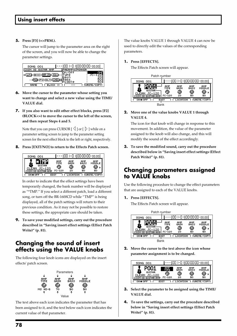
Using insert effects
5. Press [F3] (=>PRM.).
The cursor will jump to the parameter area on the right of the screen, and you will now be able to change the parameter settings.
fig.31-03d
6. Move the cursor to the parameter whose setting you want to change and select a new value using the TIME/VALUE dial.
7. If you also want to edit other effect blocks, press [F2] (BLOCK<=) to move the cursor to the left of the screen, and then repeat Steps 4 and 5.
Note that you can press CURSOR [ ] or [ ] while on a parameter setting screen to jump to the parameter setting screen for the next effect block to the left or right, respectively.
8. Press [EXIT/NO] to return to the Effects Patch screen.fig.31-04d
In order to indicate that the effect settings have been temporarily changed, the bank number will be displayed as “*TMP.” If you select a different patch, load a different song, or turn off the BR-1600CD while “TMP” is being displayed, all of the patch settings will return to their previous condition. As it may not be possible to restore these settings, the appropriate care should be taken.
9. To save your modified settings, carry out the procedure described in “Saving insert effect settings (Effect Patch Write)” (p. 81).
Changing the sound of insert effects using the VALUE knobsThe following four knob icons are displayed on the insert effects' patch screen.fig.31-60
The text above each icon indicates the parameter that has been assigned to it, and the text below each icon indicates the current value of that parameter.
The value knobs VALUE 1 through VALUE 4 can now be used to directly edit the values of the corresponding parameters.
1. Press [EFFECTS].
The Effects Patch screen will appear.fig.31-01d
2. Move one of the value knobs VALUE 1 through VALUE 4.
The icon for that knob will change in response to this movement. In addition, the value of the parameter assigned to the knob will also change, and this will modify the sound of the effect accordingly.
3. To save the modified sound, carry out the procedure described below in “Saving insert effect settings (Effect Patch Write)” (p. 81).
Changing parameters assigned to VALUE knobsUse the following procedure to change the effect parameters that are assigned to each of the VALUE knobs.
1. Press [EFFECTS].
The Effects Patch screen will appear.fig.31-01d
2. Move the cursor to the text above the icon whose parameter assignment is to be changed.
fig.31-61d
3. Select the parameter to be assigned using the TIME/VALUE dial.
4. To save the settings, carry out the procedure described below in “Saving insert effect settings (Effect Patch Write)” (p. 81).
Parameters
Value
Patch number
Bank
Patch number
Bank
78
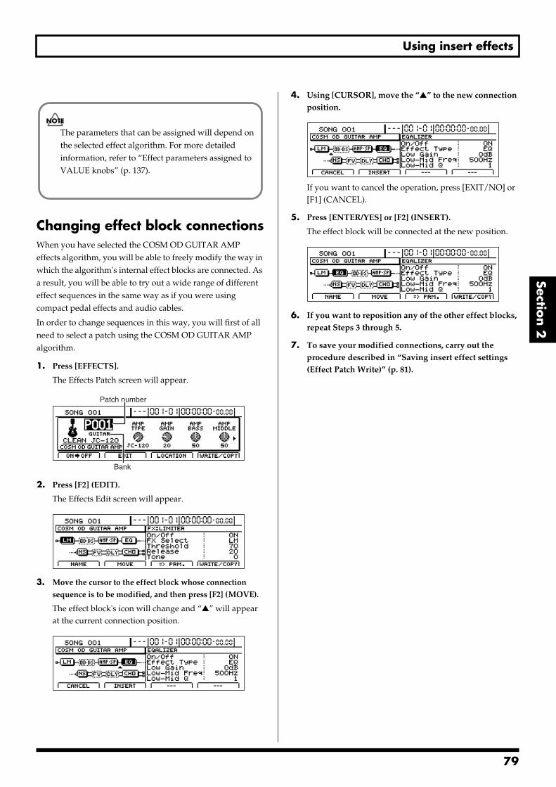
Using insert effects
Section 2
Changing effect block connectionsWhen you have selected the COSM OD GUITAR AMP effects algorithm, you will be able to freely modify the way in which the algorithm's internal effect blocks are connected. As a result, you will be able to try out a wide range of different effect sequences in the same way as if you were using compact pedal effects and audio cables.
In order to change sequences in this way, you will first of all need to select a patch using the COSM OD GUITAR AMP algorithm.
1. Press [EFFECTS].
The Effects Patch screen will appear.fig.31-01d
2. Press [F2] (EDIT).
The Effects Edit screen will appear.fig.31-02d
3. Move the cursor to the effect block whose connection sequence is to be modified, and then press [F2] (MOVE).
The effect block's icon will change and “” will appear at the current connection position.
fig.31-52d
4. Using [CURSOR], move the “” to the new connection position.
fig.31-53d
If you want to cancel the operation, press [EXIT/NO] or [F1] (CANCEL).
5. Press [ENTER/YES] or [F2] (INSERT).
The effect block will be connected at the new position.fig.31-54d
6. If you want to reposition any of the other effect blocks, repeat Steps 3 through 5.
7. To save your modified connections, carry out the procedure described in “Saving insert effect settings (Effect Patch Write)” (p. 81).
The parameters that can be assigned will depend on the selected effect algorithm. For more detailed information, refer to “Effect parameters assigned to VALUE knobs” (p. 137).
Patch number
Bank
79
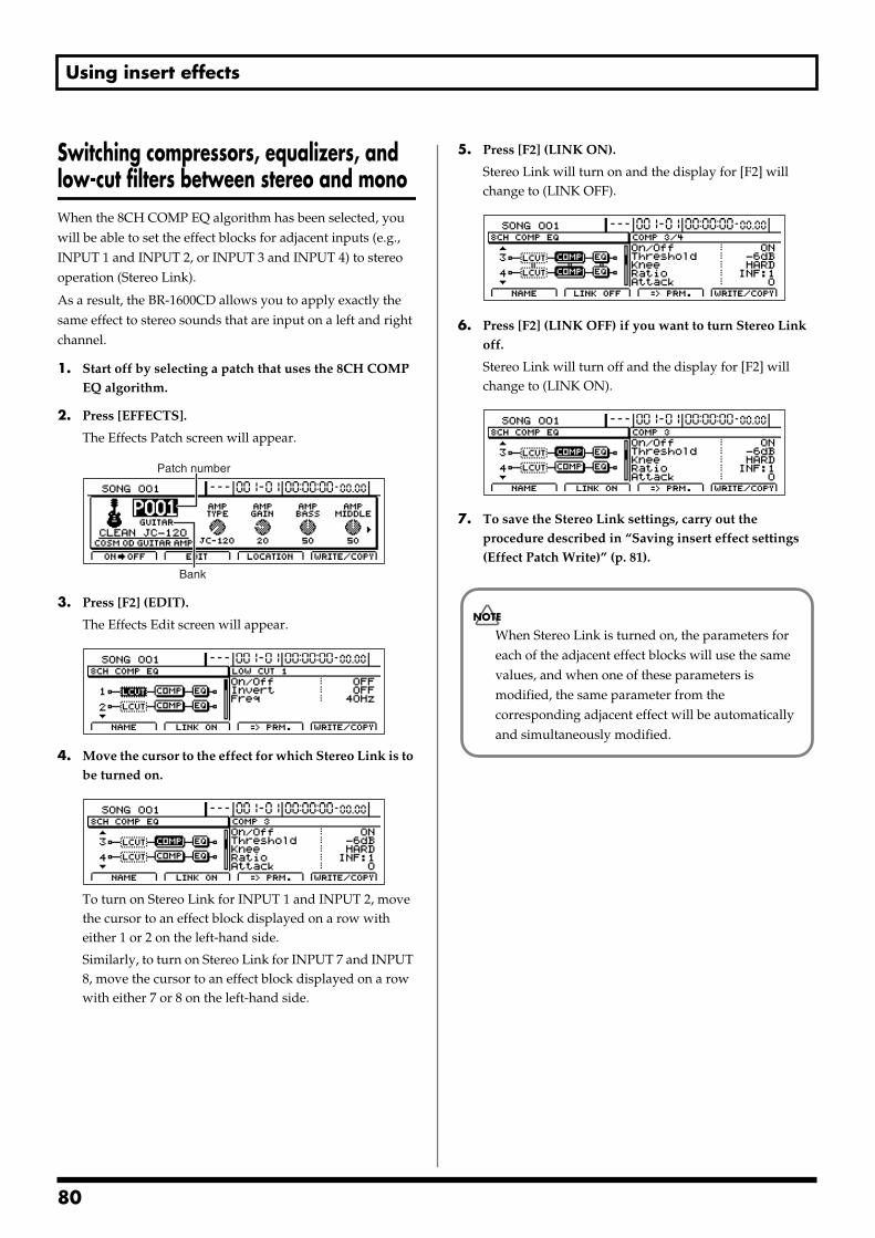
Using insert effects
Switching compressors, equalizers, and low-cut filters between stereo and monoWhen the 8CH COMP EQ algorithm has been selected, you will be able to set the effect blocks for adjacent inputs (e.g., INPUT 1 and INPUT 2, or INPUT 3 and INPUT 4) to stereo operation (Stereo Link).
As a result, the BR-1600CD allows you to apply exactly the same effect to stereo sounds that are input on a left and right channel.
1. Start off by selecting a patch that uses the 8CH COMP EQ algorithm.
2. Press [EFFECTS].
The Effects Patch screen will appear.fig.31-01d
3. Press [F2] (EDIT).
The Effects Edit screen will appear.fig.31-102d
4. Move the cursor to the effect for which Stereo Link is to be turned on.
fig.31-54ad
To turn on Stereo Link for INPUT 1 and INPUT 2, move the cursor to an effect block displayed on a row with either 1 or 2 on the left-hand side.
Similarly, to turn on Stereo Link for INPUT 7 and INPUT 8, move the cursor to an effect block displayed on a row with either 7 or 8 on the left-hand side.
5. Press [F2] (LINK ON).
Stereo Link will turn on and the display for [F2] will change to (LINK OFF).
fig.31-55d
6. Press [F2] (LINK OFF) if you want to turn Stereo Link off.
Stereo Link will turn off and the display for [F2] will change to (LINK ON).
fig.31-56d
7. To save the Stereo Link settings, carry out the procedure described in “Saving insert effect settings (Effect Patch Write)” (p. 81).
Patch number
Bank
When Stereo Link is turned on, the parameters for each of the adjacent effect blocks will use the same values, and when one of these parameters is modified, the same parameter from the corresponding adjacent effect will be automatically and simultaneously modified.
80
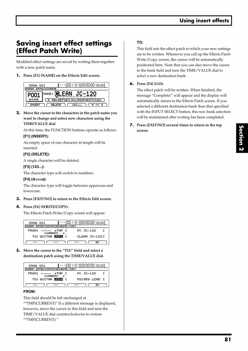
Using insert effects
Section 2
Saving insert effect settings (Effect Patch Write) Modified effect settings are saved by writing them together with a new patch name.
1. Press [F1] (NAME) on the Effects Edit screen.fig.31-05d
2. Move the cursor to the characters in the patch name you want to change and select new characters using the TIME/VALUE dial.
At this time, the FUNCTION buttons operate as follows.
[F1] (INSERT):
An empty space of one character in length will be inserted.
[F2] (DELETE):
A single character will be deleted.
[F3] (123...):
The character type will switch to numbers.
[F4] (A<=>a):
The character type will toggle between uppercase and lowercase.
3. Press [EXIT/NO] to return to the Effects Edit screen.
4. Press [F4] (WRITE/COPY).
The Effects Patch Write/Copy screen will appear.fig.31-06d
5. Move the cursor to the “TO:” field and select a destination patch using the TIME/VALUE dial.
fig.31-07d
FROM:
This field should be left unchanged at “*TMP(CURRENT)” If a different message is displayed, however, move the cursor to this field and turn the TIME/VALUE dial counterclockwise to restore “*TMP(CURRENT).”
TO:
This field sets the effect patch to which your new settings are to be written. Whenever you call up the Effects Patch Write/Copy screen, the cursor will be automatically positioned here. Note that you can also move the cursor to the bank field and turn the TIME/VALUE dial to select a new destination bank.
6. Press [F4] (GO).
The effect patch will be written. When finished, the message “Complete!” will appear and the display will automatically return to the Effects Patch screen. If you selected a different destination bank than that specified with the INPUT SELECT button, this new bank selection will be maintained after writing has been completed.
7. Press [EXIT/NO] several times to return to the top screen.
81
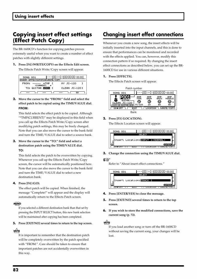
Using insert effects
Copying insert effect settings (Effect Patch Copy) The BR-1600CD’s function for copying patches proves extremely useful when you want to create a number of effect patches with slightly different settings.
1. Press [F4] (WRITE/COPY) on the Effects Edit screen.
The Effects Patch Write/Copy screen will appear.fig.31-06d
2. Move the cursor to the “FROM:” field and select the effect patch to be copied using the TIME/VALUE dial.
FROM:
This field selects the effect patch to be copied. Although “*TMP(CURRENT)” may be displayed in this field when you call up the Effects Patch Write/Copy screen after modifying patch settings, this may be freely changed. Note that you can also move the cursor to the bank field and turn the TIME/VALUE dial to select a source bank.
3. Move the cursor to the “TO:” field and select a destination patch using the TIME/VALUE dial.
TO:
This field selects the patch to be overwritten by copying. Whenever you call up the Effects Patch Write/Copy screen, the cursor will be automatically positioned here. Note that you can also move the cursor to the bank field and turn the TIME/VALUE dial to select a new destination bank.
4. Press [F4] (GO).
The effect patch will be copied. When finished, the message “Complete!” will appear and the display will automatically return to the Effects Patch screen.
If you selected a different destination bank than that set by pressing the INPUT SELECT button, this new bank selection will be maintained after copying has been completed.
5. Press [EXIT/NO] several times to return to the top screen.
It is important to remember that the destination patch will be completely overwritten by the patch specified with “FROM:”. Care should be taken to ensure that important patches are not accidentally overwritten in this way.
Changing insert effect connectionsWhenever you create a new song, the insert effects will be initially inserted into the input channels, and this is done to ensure that performances can be monitored and recorded with the effects applied. You can, however, modify this connection pattern if so required. By changing the insert effect connections as described below, you can set up the BR-1600CD for use in various different situations.
1. Press [EFFECTS].
The Effects Patch screen will appear.fig.31-01d
2. Press [F3] (LOCATION).
The Effects Location screen will appear.fig.31-10d
3. Change the connection using the TIME/VALUE dial.
Refer to “About insert effect connections.”fig.31-11d
4. Press [ENTER/YES] to close the message.
5. Press [EXIT/NO] several times to return to the top screen.
6. If you wish to store the modified connections, save the current song (p. 72).
If you load another song or turn off the BR-1600CD without saving the current song, your changes will be lost.
Patch number
Bank
82
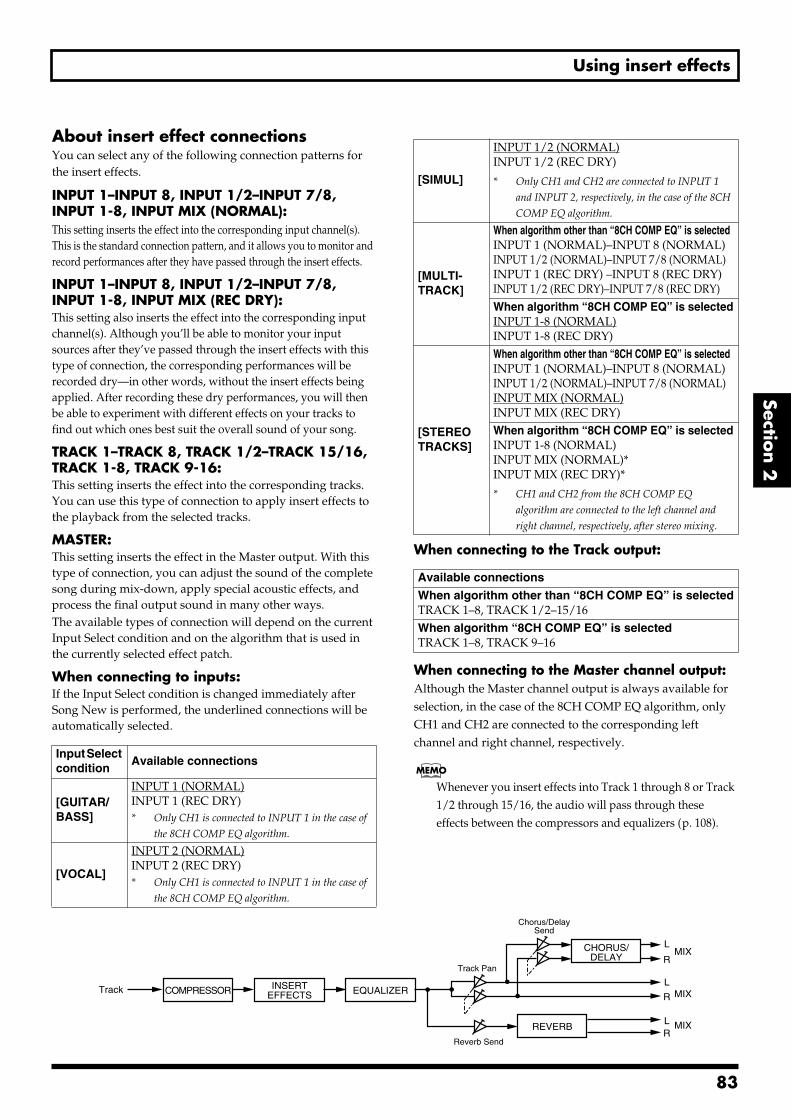
Using insert effects
Section 2
About insert effect connectionsYou can select any of the following connection patterns for the insert effects.
INPUT 1–INPUT 8, INPUT 1/2–INPUT 7/8, INPUT 1-8, INPUT MIX (NORMAL):This setting inserts the effect into the corresponding input channel(s). This is the standard connection pattern, and it allows you to monitor and record performances after they have passed through the insert effects.
INPUT 1–INPUT 8, INPUT 1/2–INPUT 7/8, INPUT 1-8, INPUT MIX (REC DRY):This setting also inserts the effect into the corresponding input channel(s). Although you’ll be able to monitor your input sources after they’ve passed through the insert effects with this type of connection, the corresponding performances will be recorded dry—in other words, without the insert effects being applied. After recording these dry performances, you will then be able to experiment with different effects on your tracks to find out which ones best suit the overall sound of your song.
TRACK 1–TRACK 8, TRACK 1/2–TRACK 15/16, TRACK 1-8, TRACK 9-16: This setting inserts the effect into the corresponding tracks. You can use this type of connection to apply insert effects to the playback from the selected tracks.
MASTER:This setting inserts the effect in the Master output. With this type of connection, you can adjust the sound of the complete song during mix-down, apply special acoustic effects, and process the final output sound in many other ways.The available types of connection will depend on the current Input Select condition and on the algorithm that is used in the currently selected effect patch.
When connecting to inputs:If the Input Select condition is changed immediately after Song New is performed, the underlined connections will be automatically selected.
When connecting to the Track output:
When connecting to the Master channel output:Although the Master channel output is always available for selection, in the case of the 8CH COMP EQ algorithm, only CH1 and CH2 are connected to the corresponding left channel and right channel, respectively.
Whenever you insert effects into Track 1 through 8 or Track 1/2 through 15/16, the audio will pass through these effects between the compressors and equalizers (p. 108).
Input Select condition
Available connections
[GUITAR/BASS]
INPUT 1 (NORMAL)INPUT 1 (REC DRY)* Only CH1 is connected to INPUT 1 in the case of
the 8CH COMP EQ algorithm.
[VOCAL]
INPUT 2 (NORMAL)INPUT 2 (REC DRY)* Only CH1 is connected to INPUT 1 in the case of
the 8CH COMP EQ algorithm.
[SIMUL]
INPUT 1/2 (NORMAL)INPUT 1/2 (REC DRY)
* Only CH1 and CH2 are connected to INPUT 1
and INPUT 2, respectively, in the case of the 8CH
COMP EQ algorithm.
[MULTI- TRACK]
When algorithm other than “8CH COMP EQ” is selectedINPUT 1 (NORMAL)–INPUT 8 (NORMAL)INPUT 1/2 (NORMAL)–INPUT 7/8 (NORMAL)INPUT 1 (REC DRY) –INPUT 8 (REC DRY)INPUT 1/2 (REC DRY)–INPUT 7/8 (REC DRY)When algorithm “8CH COMP EQ” is selectedINPUT 1-8 (NORMAL)INPUT 1-8 (REC DRY)
[STEREO TRACKS]
When algorithm other than “8CH COMP EQ” is selectedINPUT 1 (NORMAL)–INPUT 8 (NORMAL)INPUT 1/2 (NORMAL)–INPUT 7/8 (NORMAL)INPUT MIX (NORMAL)INPUT MIX (REC DRY)When algorithm “8CH COMP EQ” is selectedINPUT 1-8 (NORMAL)INPUT MIX (NORMAL)*INPUT MIX (REC DRY)*
* CH1 and CH2 from the 8CH COMP EQ
algorithm are connected to the left channel and
right channel, respectively, after stereo mixing.
Available connections
When algorithm other than “8CH COMP EQ” is selectedTRACK 1–8, TRACK 1/2–15/16When algorithm “8CH COMP EQ” is selectedTRACK 1–8, TRACK 9–16
Track
REVERB
CHORUS/DELAY
EQUALIZERCOMPRESSOR
LMIX
MIX
MIX
R
L
R
LR
Chorus/DelaySend
Reverb Send
Track Pan
INSERTEFFECTS
83
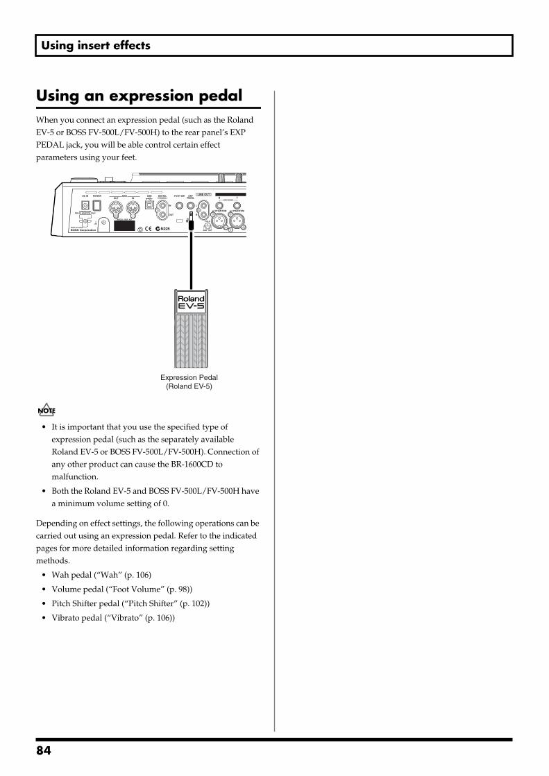
Using insert effects
Using an expression pedalWhen you connect an expression pedal (such as the Roland EV-5 or BOSS FV-500L/FV-500H) to the rear panel’s EXP PEDAL jack, you will be able control certain effect parameters using your feet.fig.53-00
• It is important that you use the specified type of expression pedal (such as the separately available Roland EV-5 or BOSS FV-500L/FV-500H). Connection of any other product can cause the BR-1600CD to malfunction.
• Both the Roland EV-5 and BOSS FV-500L/FV-500H have a minimum volume setting of 0.
Depending on effect settings, the following operations can be carried out using an expression pedal. Refer to the indicated pages for more detailed information regarding setting methods.
• Wah pedal (“Wah” (p. 106)
• Volume pedal (“Foot Volume” (p. 98))
• Pitch Shifter pedal (“Pitch Shifter” (p. 102))
• Vibrato pedal (“Vibrato” (p. 106))
Expression Pedal(Roland EV-5)
84
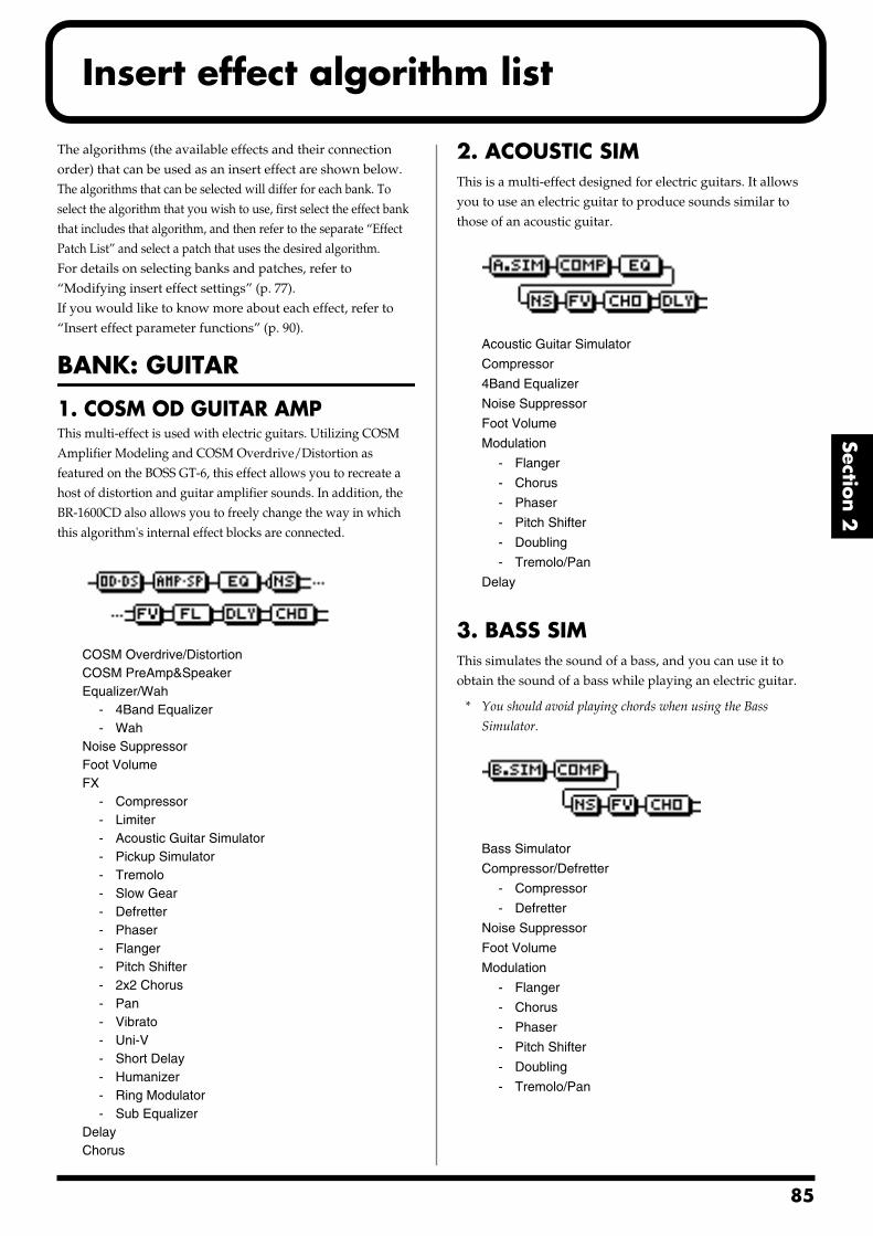
Insert effect algorithm list
Section 2
The algorithms (the available effects and their connection order) that can be used as an insert effect are shown below.The algorithms that can be selected will differ for each bank. To select the algorithm that you wish to use, first select the effect bank that includes that algorithm, and then refer to the separate “Effect Patch List” and select a patch that uses the desired algorithm.For details on selecting banks and patches, refer to “Modifying insert effect settings” (p. 77).If you would like to know more about each effect, refer to “Insert effect parameter functions” (p. 90).
BANK: GUITAR
1. COSM OD GUITAR AMPThis multi-effect is used with electric guitars. Utilizing COSM Amplifier Modeling and COSM Overdrive/Distortion as featured on the BOSS GT-6, this effect allows you to recreate a host of distortion and guitar amplifier sounds. In addition, the BR-1600CD also allows you to freely change the way in which this algorithm's internal effect blocks are connected.fig.31-12
COSM Overdrive/DistortionCOSM PreAmp&SpeakerEqualizer/Wah
- 4Band Equalizer- Wah
Noise SuppressorFoot VolumeFX
- Compressor- Limiter- Acoustic Guitar Simulator- Pickup Simulator- Tremolo- Slow Gear- Defretter- Phaser- Flanger- Pitch Shifter- 2x2 Chorus- Pan- Vibrato- Uni-V- Short Delay- Humanizer- Ring Modulator- Sub Equalizer
DelayChorus
2. ACOUSTIC SIMThis is a multi-effect designed for electric guitars. It allows you to use an electric guitar to produce sounds similar to those of an acoustic guitar.fig.31-13
Acoustic Guitar Simulator
Compressor
4Band Equalizer
Noise Suppressor
Foot Volume
Modulation
- Flanger
- Chorus
- Phaser
- Pitch Shifter
- Doubling
- Tremolo/Pan
Delay
3. BASS SIMThis simulates the sound of a bass, and you can use it to obtain the sound of a bass while playing an electric guitar.
* You should avoid playing chords when using the Bass
Simulator.fig.31-14
Bass Simulator
Compressor/Defretter
- Compressor
- Defretter
Noise Suppressor
Foot Volume
Modulation
- Flanger
- Chorus
- Phaser
- Pitch Shifter
- Doubling
- Tremolo/Pan
85
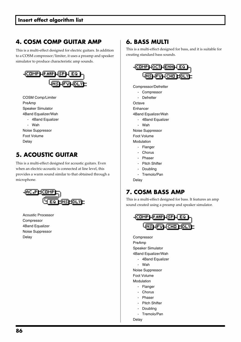
Insert effect algorithm list
4. COSM COMP GUITAR AMPThis is a multi-effect designed for electric guitars. In addition to a COSM compressor/limiter, it uses a preamp and speaker simulator to produce characteristic amp sounds.fig.31-15
COSM Comp/Limiter
PreAmp
Speaker Simulator
4Band Equalizer/Wah
- 4Band Equalizer
- Wah
Noise Suppressor
Foot Volume
Delay
5. ACOUSTIC GUITARThis is a multi-effect designed for acoustic guitars. Even when an electric-acoustic is connected at line level, this provides a warm sound similar to that obtained through a microphone.fig.31-16
Acoustic Processor
Compressor
4Band Equalizer
Noise Suppressor
Delay
6. BASS MULTIThis is a multi-effect designed for bass, and it is suitable for creating standard bass sounds.fig.31-17
Compressor/Defretter
- Compressor
- Defretter
Octave
Enhancer
4Band Equalizer/Wah
- 4Band Equalizer
- Wah
Noise Suppressor
Foot Volume
Modulation
- Flanger
- Chorus
- Phaser
- Pitch Shifter
- Doubling
- Tremolo/Pan
Delay
7. COSM BASS AMPThis is a multi-effect designed for bass. It features an amp sound created using a preamp and speaker simulator.fig.31-18
Compressor
PreAmp
Speaker Simulator
4Band Equalizer/Wah
- 4Band Equalizer
- Wah
Noise Suppressor
Foot Volume
Modulation
- Flanger
- Chorus
- Phaser
- Pitch Shifter
- Doubling
- Tremolo/Pan
Delay
86
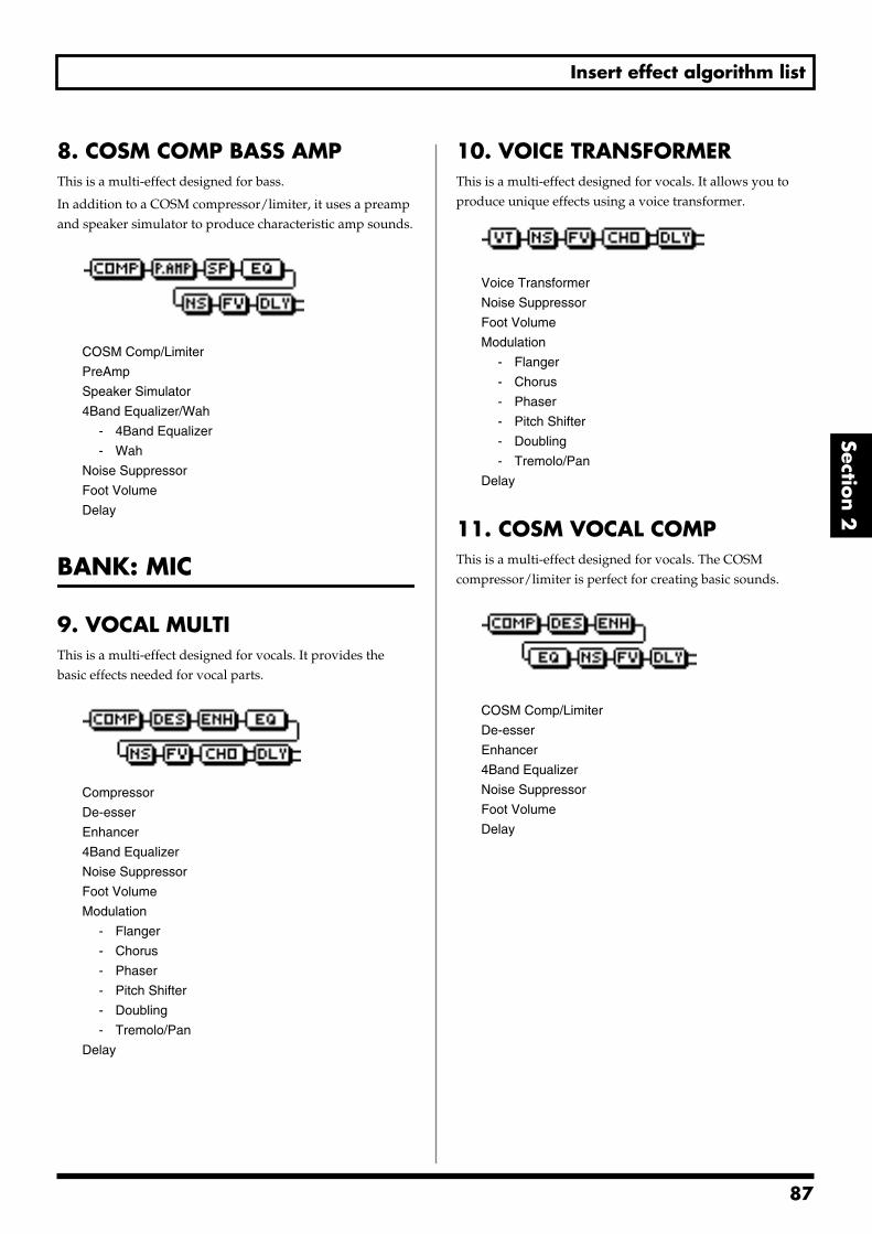
Insert effect algorithm list
Section 2
8. COSM COMP BASS AMPThis is a multi-effect designed for bass.
In addition to a COSM compressor/limiter, it uses a preamp and speaker simulator to produce characteristic amp sounds.fig.31-19
COSM Comp/Limiter
PreAmp
Speaker Simulator
4Band Equalizer/Wah
- 4Band Equalizer
- Wah
Noise Suppressor
Foot Volume
Delay
BANK: MIC
9. VOCAL MULTIThis is a multi-effect designed for vocals. It provides the basic effects needed for vocal parts.fig.31-20
Compressor
De-esser
Enhancer
4Band Equalizer
Noise Suppressor
Foot Volume
Modulation
- Flanger
- Chorus
- Phaser
- Pitch Shifter
- Doubling
- Tremolo/Pan
Delay
10. VOICE TRANSFORMERThis is a multi-effect designed for vocals. It allows you to produce unique effects using a voice transformer.fig.31-21
Voice Transformer
Noise Suppressor
Foot Volume
Modulation
- Flanger
- Chorus
- Phaser
- Pitch Shifter
- Doubling
- Tremolo/Pan
Delay
11. COSM VOCAL COMPThis is a multi-effect designed for vocals. The COSM compressor/limiter is perfect for creating basic sounds.fig.31-22
COSM Comp/Limiter
De-esser
Enhancer
4Band Equalizer
Noise Suppressor
Foot Volume
Delay
87
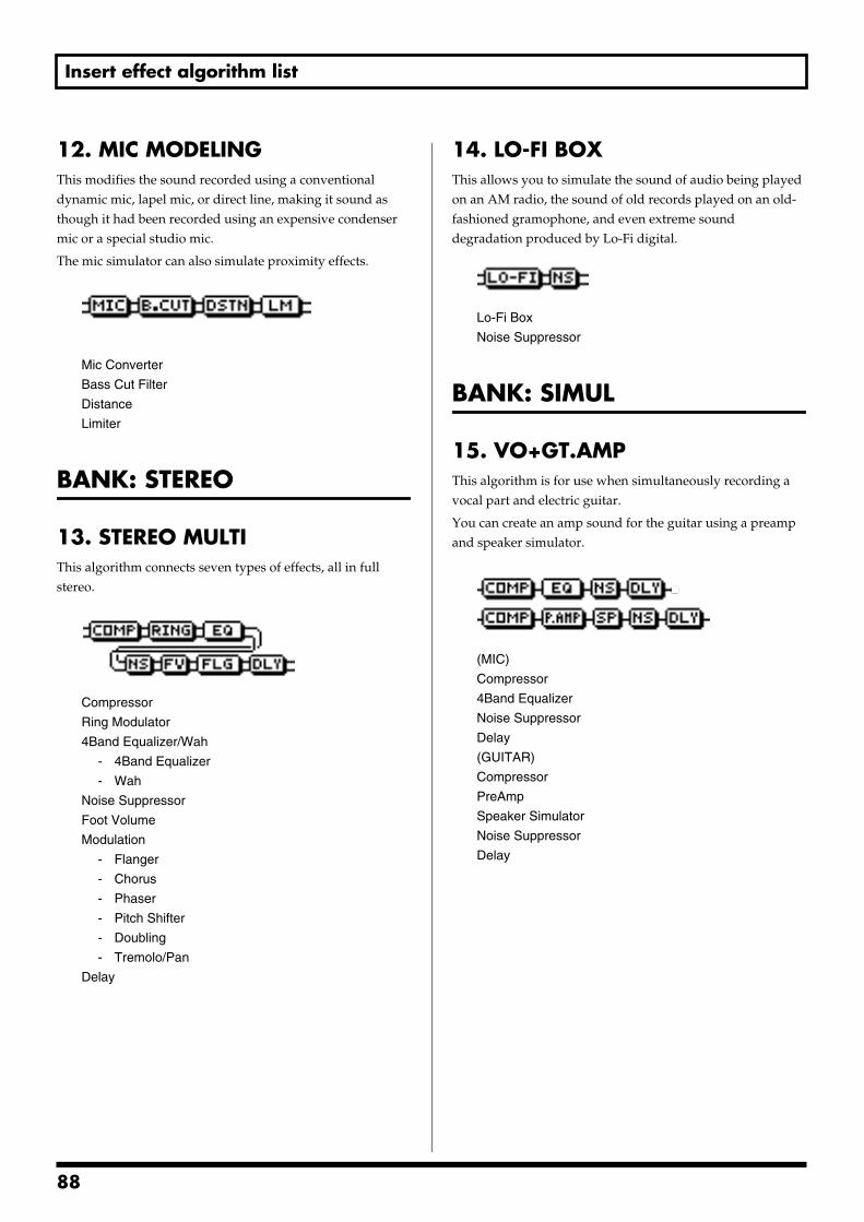
Insert effect algorithm list
12. MIC MODELINGThis modifies the sound recorded using a conventional dynamic mic, lapel mic, or direct line, making it sound as though it had been recorded using an expensive condenser mic or a special studio mic.
The mic simulator can also simulate proximity effects.fig.31-23
Mic Converter
Bass Cut Filter
Distance
Limiter
BANK: STEREO
13. STEREO MULTIThis algorithm connects seven types of effects, all in full stereo.fig.31-24
Compressor
Ring Modulator
4Band Equalizer/Wah
- 4Band Equalizer
- Wah
Noise Suppressor
Foot Volume
Modulation
- Flanger
- Chorus
- Phaser
- Pitch Shifter
- Doubling
- Tremolo/Pan
Delay
14. LO-FI BOXThis allows you to simulate the sound of audio being played on an AM radio, the sound of old records played on an old-fashioned gramophone, and even extreme sound degradation produced by Lo-Fi digital.fig.31-25
Lo-Fi Box
Noise Suppressor
BANK: SIMUL
15. VO+GT.AMPThis algorithm is for use when simultaneously recording a vocal part and electric guitar.
You can create an amp sound for the guitar using a preamp and speaker simulator.fig.31-26
(MIC)
Compressor
4Band Equalizer
Noise Suppressor
Delay
(GUITAR)
Compressor
PreAmp
Speaker Simulator
Noise Suppressor
Delay
88
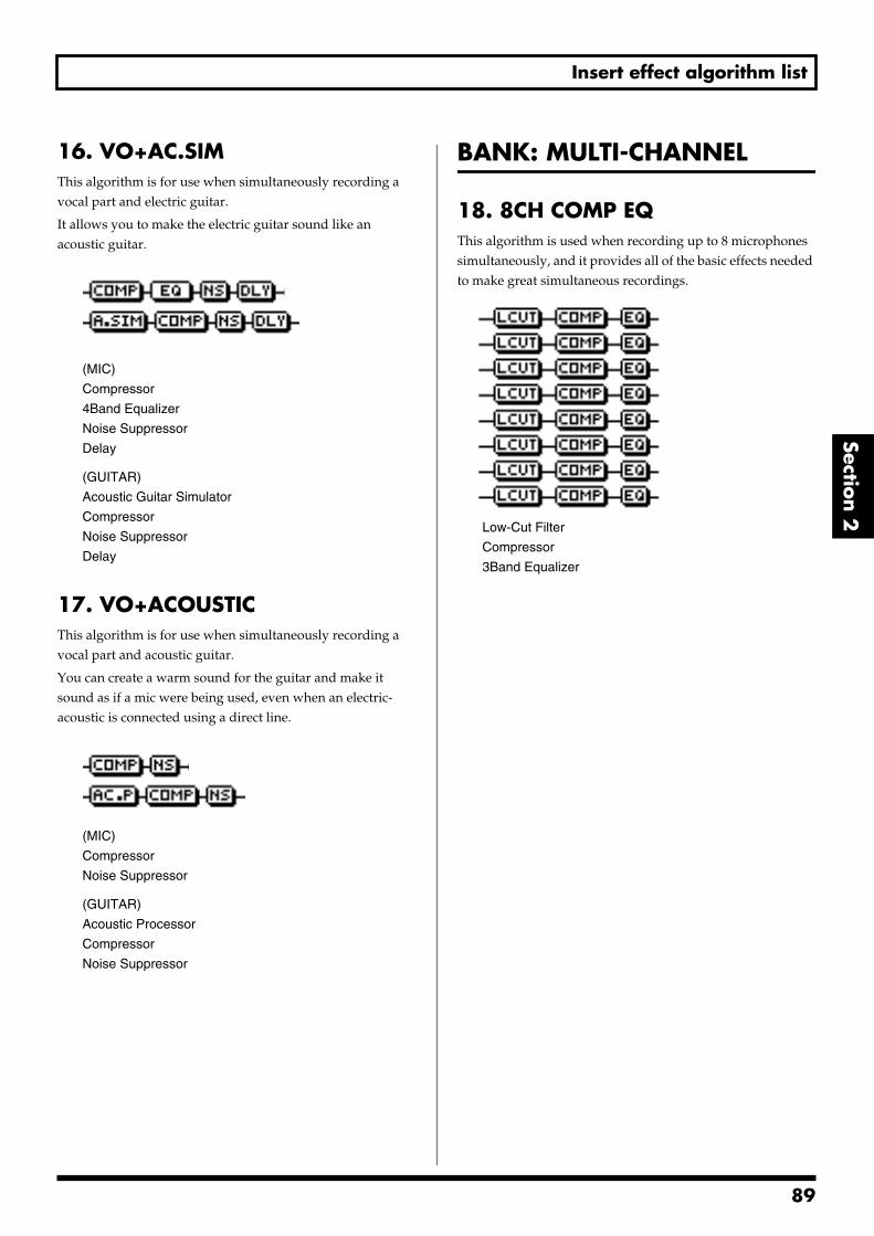
Insert effect algorithm list
Section 2
16. VO+AC.SIMThis algorithm is for use when simultaneously recording a vocal part and electric guitar.
It allows you to make the electric guitar sound like an acoustic guitar.fig.31-27
(MIC)
Compressor
4Band Equalizer
Noise Suppressor
Delay
(GUITAR)
Acoustic Guitar Simulator
Compressor
Noise Suppressor
Delay
17. VO+ACOUSTICThis algorithm is for use when simultaneously recording a vocal part and acoustic guitar.
You can create a warm sound for the guitar and make it sound as if a mic were being used, even when an electric-acoustic is connected using a direct line.fig.31-28
(MIC)
Compressor
Noise Suppressor
(GUITAR)
Acoustic Processor
Compressor
Noise Suppressor
BANK: MULTI-CHANNEL
18. 8CH COMP EQThis algorithm is used when recording up to 8 microphones simultaneously, and it provides all of the basic effects needed to make great simultaneous recordings. fig.31-29
Low-Cut Filter
Compressor
3Band Equalizer
89
9
Insert effect parameter functions
Acoustic Guitar SimulatorThis simulates the sound of an acoustic guitar. It allows you to use an electric guitar to produce sounds similar to those of an acoustic guitar.
It will be easier to achieve the desired effect if you set the pickup selector of your guitar to the front position.
* This effect can be used when “COSM OD GUITAR AMP,”
“ACOUSTIC SIM,” or “VO+AC.SIM” algorithms are selected.
Effect On/Off OFF, ONThis parameter turns the acoustic guitar simulator effect on and off.
Level 0–100This adjusts the volume of the acoustic guitar simulator.
When “COSM OD GUITAR AMP” algorithm is selected
* This effect can be used when FX “FX Select” parameter is set to “AC.”
Top 0–100This adjusts the interference to the strings made by the top plate. That is, it adjusts the attack sense or harmonic contents.
Body 0–+100This adjusts the resonance of the sound caused by the body. That is, it adjusts the softness and fatness of the sound which is the typical characteristics of acoustic guitars.
When “ACOUSTIC SIM” or “VO+AC.SIM” algorithm is selected
Pickup Type SINGLE, HUMBUCKSet this to the type of pickup on the guitar being played.
CharacterThis selects one of four sound types.
STD (STANDARD):A normal acoustic guitar.
JUMBO:An acoustic guitar with a body that is bigger than that of the STANDARD guitar. This guitar has a more powerful bass sound.
ENHANCE:An acoustic guitar with a more responsive attack. With this setting, the guitar will retain a higher degree of presence in almost any situation.
PIEZO:Simulates the sound you would get from a pickup installed on an electric-acoustic guitar. With this setting, a certain amount of compression will be applied during the attack.
Top-Hi -100–+100This adjusts the level of the direct sound from the strings—in other words, it adjusts the harmonic content.
Top-Mid -100–+100This adjusts the way in which the top plate affects the strings—in other words, it adjusts the sense of attack.
Body -100–+100This adjusts the resonance generated by the body—in other words, it adjusts the softness and fatness of the sound to simulate the typical characteristics of acoustic guitars.
* If Top-Hi, Top-Mid, and Body are all set to “-100,” there will be no
sound.
Acoustic ProcessorThis processor allows you to change the sound produced by the pickup on an electric-acoustic guitar, creating a richer sound similar to that obtained with a microphone placed close to the guitar. Best results will be achieved when stereo output is used.
Effect On/Off OFF, ONThis parameter turns the acoustic processor effect on or off.
Body 0–100This adjusts the resonance generated by the body—in other words, it adjusts the softness and fatness of the sound to simulate the typical characteristics of acoustic guitars.
Mic Distance 0–100This adjusts the simulated distance between the acoustic guitar and the microphone used to capture its sound.
Level 0–100This adjusts the overall volume of the acoustic processor.
The trademarks listed in this document are the property of their respective companies. Said companies are not affiliated with BOSS and have neither licensed nor authorized the BOSS BR-1600CD. Their trademarks are used solely to identify equipment whose sound is simulated by the BR-1600CD.
0
Insert effect parameter functions
Section 2
3 Band EqualizerThis is the 3-band equalizer.
* This effect can be used when “8CH COMP EQ” algorithm is selected.
High Type SHLV, PEAKSets the equalizer type for the high range.
SHLV:This selects the shelving type equalization.
PEAK:This selects the peaking type equalization.
High Gain -20–+20 dBThis parameter sets the gain (amount of boost or cut) for the high-range equalizer.
High Freq 800 Hz–16.0 kHzThis parameter sets the frequency for the high range equalizer.
High Q 0.5–16.0This parameter sets the range of change in gain for the frequency set by “High Freq.” A larger value results in a narrower range of change.
This parameter is only valid when “High Type” has been set to “PEAK.”
Mid Gain -20–+20 dBThis parameter sets the gain (amount of boost or cut) for the midrange equalizer.
Mid Freq 200 Hz–4.0 kHzThis parameter sets the central frequency for the midrange equalizer.
Mid Q 0.3–16.0This parameter sets the range of change in gain for the frequency set by “Mid Freq.” A larger value results in a narrower range of change.
Low Type SHLV, PEAKSets the equalizer type for the low range.
SHLV:This selects the shelving type equalization.
PEAK:This selects the peaking type equalization.
Low Gain -20–+20 dBThis parameter sets the gain (amount of boost or cut) for the low range equalizer.
Low Freq 40 Hz–800 HzThis parameter sets the frequency for the low range equalizer.
Low Q 0.3–16.0This parameter sets the range of change in gain for the frequency set by “Low Freq.” A larger value results in a narrower range of change.
This parameter is only valid when “Low Type” has been set to “PEAK.”
4 Band EqualizerThis is the 4-band equalizer.
* This effect can be used in the “COSM OD GUITAR AMP,” “BASS
MULTI,” “COSM BASS AMP” or “STEREO MULTI” algorithm
when 4 Band Equalizer/Wah “Effect Type” parameter is set to “EQ.”
Effect On/Off OFF, ONThis parameter turns the equalizer on or off.
Low Gain -20–+20 dBThis parameter sets the gain (amount of boost or cut) for the low range equalizer.
Low-Mid Freq 100 Hz–10.0 kHzThis parameter sets the central frequency for the low-midrange equalizer.
Low-Mid Q 0.5–16.0This parameter sets the range of change in gain for the frequency set by “Low-Mid Freq” A larger value results in a narrower range of change.
Low-Mid Gain -20–+20 dBThis parameter sets the gain (amount of boost or cut) for the low- midrange equalizer.
Hi-Mid Freq 100 Hz–10.0 kHzThis parameter sets the frequency for the high-midrange equalizer.
Hi-Mid Q 0.5–16.0This parameter sets the range of change in gain for the frequency set by “Hi-Mid Freq” A larger value results in a narrower range of change.
Hi-Mid Gain -20–+20 dBThis parameter sets the gain (amount of boost or cut) for the high- midrange equalizer.
High Gain -20–+20 dBThis parameter sets the gain (amount of boost or cut) for the high-range equalizer.
Level -20–+20 dBThis sets the overall volume level after equalization.
91
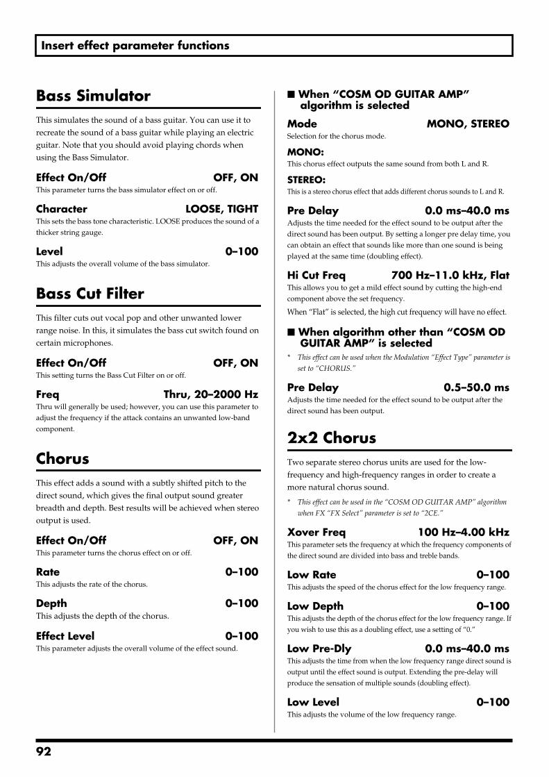
Insert effect parameter functions
Bass SimulatorThis simulates the sound of a bass guitar. You can use it to recreate the sound of a bass guitar while playing an electric guitar. Note that you should avoid playing chords when using the Bass Simulator.
Effect On/Off OFF, ONThis parameter turns the bass simulator effect on or off.
Character LOOSE, TIGHTThis sets the bass tone characteristic. LOOSE produces the sound of a thicker string gauge.
Level 0–100This adjusts the overall volume of the bass simulator.
Bass Cut FilterThis filter cuts out vocal pop and other unwanted lower range noise. In this, it simulates the bass cut switch found on certain microphones.
Effect On/Off OFF, ONThis setting turns the Bass Cut Filter on or off.
Freq Thru, 20–2000 HzThru will generally be used; however, you can use this parameter to adjust the frequency if the attack contains an unwanted low-band component.
ChorusThis effect adds a sound with a subtly shifted pitch to the direct sound, which gives the final output sound greater breadth and depth. Best results will be achieved when stereo output is used.
Effect On/Off OFF, ONThis parameter turns the chorus effect on or off.
Rate 0–100This adjusts the rate of the chorus.
Depth 0–100This adjusts the depth of the chorus.
Effect Level 0–100This parameter adjusts the overall volume of the effect sound.
When “COSM OD GUITAR AMP” algorithm is selected
Mode MONO, STEREOSelection for the chorus mode.
MONO:This chorus effect outputs the same sound from both L and R.
STEREO:This is a stereo chorus effect that adds different chorus sounds to L and R.
Pre Delay 0.0 ms–40.0 msAdjusts the time needed for the effect sound to be output after the direct sound has been output. By setting a longer pre delay time, you can obtain an effect that sounds like more than one sound is being played at the same time (doubling effect).
Hi Cut Freq 700 Hz–11.0 kHz, FlatThis allows you to get a mild effect sound by cutting the high-end component above the set frequency.
When “Flat” is selected, the high cut frequency will have no effect.
When algorithm other than “COSM OD GUITAR AMP” is selected
* This effect can be used when the Modulation “Effect Type” parameter is
set to “CHORUS.”
Pre Delay 0.5–50.0 msAdjusts the time needed for the effect sound to be output after the direct sound has been output.
2x2 ChorusTwo separate stereo chorus units are used for the low-frequency and high-frequency ranges in order to create a more natural chorus sound.
* This effect can be used in the “COSM OD GUITAR AMP” algorithm
when FX “FX Select” parameter is set to “2CE.”
Xover Freq 100 Hz–4.00 kHzThis parameter sets the frequency at which the frequency components of the direct sound are divided into bass and treble bands.
Low Rate 0–100This adjusts the speed of the chorus effect for the low frequency range.
Low Depth 0–100This adjusts the depth of the chorus effect for the low frequency range. If you wish to use this as a doubling effect, use a setting of “0.”
Low Pre-Dly 0.0 ms–40.0 msThis adjusts the time from when the low frequency range direct sound is output until the effect sound is output. Extending the pre-delay will produce the sensation of multiple sounds (doubling effect).
Low Level 0–100This adjusts the volume of the low frequency range.
92
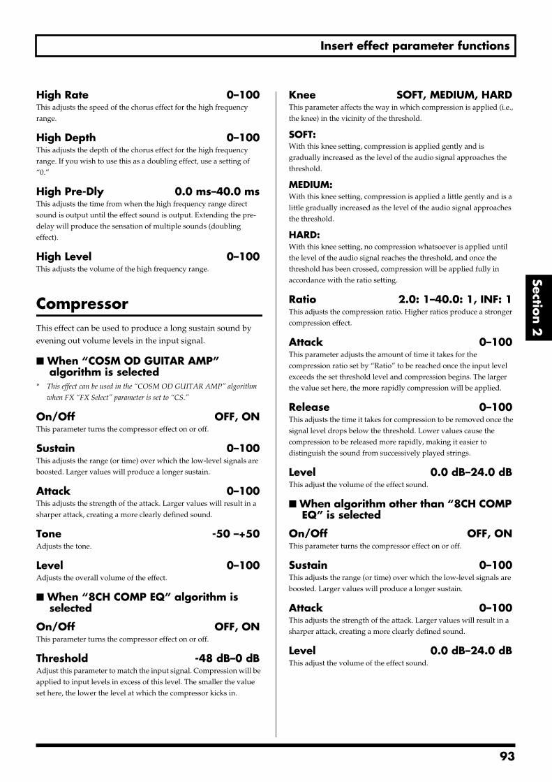
Insert effect parameter functions
Section 2
High Rate 0–100This adjusts the speed of the chorus effect for the high frequency range.
High Depth 0–100This adjusts the depth of the chorus effect for the high frequency range. If you wish to use this as a doubling effect, use a setting of “0.”
High Pre-Dly 0.0 ms–40.0 msThis adjusts the time from when the high frequency range direct sound is output until the effect sound is output. Extending the pre-delay will produce the sensation of multiple sounds (doubling effect).
High Level 0–100This adjusts the volume of the high frequency range.
CompressorThis effect can be used to produce a long sustain sound by evening out volume levels in the input signal.
When “COSM OD GUITAR AMP” algorithm is selected
* This effect can be used in the “COSM OD GUITAR AMP” algorithm
when FX “FX Select” parameter is set to “CS.”
On/Off OFF, ONThis parameter turns the compressor effect on or off.
Sustain 0–100This adjusts the range (or time) over which the low-level signals are boosted. Larger values will produce a longer sustain.
Attack 0–100This adjusts the strength of the attack. Larger values will result in a sharper attack, creating a more clearly defined sound.
Tone -50 –+50Adjusts the tone.
Level 0–100Adjusts the overall volume of the effect.
When “8CH COMP EQ” algorithm is selected
On/Off OFF, ONThis parameter turns the compressor effect on or off.
Threshold -48 dB–0 dBAdjust this parameter to match the input signal. Compression will be applied to input levels in excess of this level. The smaller the value set here, the lower the level at which the compressor kicks in.
Knee SOFT, MEDIUM, HARDThis parameter affects the way in which compression is applied (i.e., the knee) in the vicinity of the threshold.
SOFT:With this knee setting, compression is applied gently and is gradually increased as the level of the audio signal approaches the threshold.
MEDIUM:With this knee setting, compression is applied a little gently and is a little gradually increased as the level of the audio signal approaches the threshold.
HARD:With this knee setting, no compression whatsoever is applied until the level of the audio signal reaches the threshold, and once the threshold has been crossed, compression will be applied fully in accordance with the ratio setting.
Ratio 2.0: 1–40.0: 1, INF: 1This adjusts the compression ratio. Higher ratios produce a stronger compression effect.
Attack 0–100This parameter adjusts the amount of time it takes for the compression ratio set by “Ratio” to be reached once the input level exceeds the set threshold level and compression begins. The larger the value set here, the more rapidly compression will be applied.
Release 0–100This adjusts the time it takes for compression to be removed once the signal level drops below the threshold. Lower values cause the compression to be released more rapidly, making it easier to distinguish the sound from successively played strings.
Level 0.0 dB–24.0 dBThis adjust the volume of the effect sound.
When algorithm other than “8CH COMP EQ” is selected
On/Off OFF, ONThis parameter turns the compressor effect on or off.
Sustain 0–100This adjusts the range (or time) over which the low-level signals are boosted. Larger values will produce a longer sustain.
Attack 0–100This adjusts the strength of the attack. Larger values will result in a sharper attack, creating a more clearly defined sound.
Level 0.0 dB–24.0 dBThis adjust the volume of the effect sound.
93
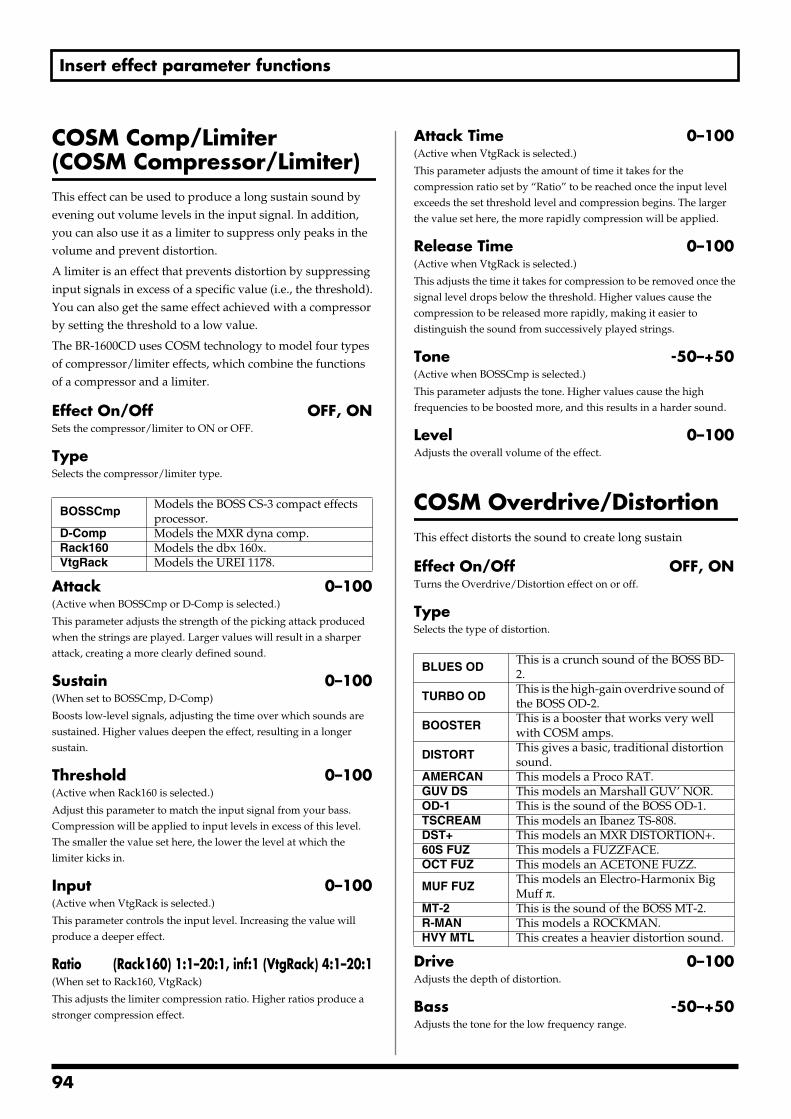
Insert effect parameter functions
COSM Comp/Limiter(COSM Compressor/Limiter)This effect can be used to produce a long sustain sound by evening out volume levels in the input signal. In addition, you can also use it as a limiter to suppress only peaks in the volume and prevent distortion.
A limiter is an effect that prevents distortion by suppressing input signals in excess of a specific value (i.e., the threshold). You can also get the same effect achieved with a compressor by setting the threshold to a low value.
The BR-1600CD uses COSM technology to model four types of compressor/limiter effects, which combine the functions of a compressor and a limiter.
Effect On/Off OFF, ONSets the compressor/limiter to ON or OFF.
TypeSelects the compressor/limiter type.
Attack 0–100(Active when BOSSCmp or D-Comp is selected.)
This parameter adjusts the strength of the picking attack produced when the strings are played. Larger values will result in a sharper attack, creating a more clearly defined sound.
Sustain 0–100(When set to BOSSCmp, D-Comp)
Boosts low-level signals, adjusting the time over which sounds are sustained. Higher values deepen the effect, resulting in a longer sustain.
Threshold 0–100(Active when Rack160 is selected.)
Adjust this parameter to match the input signal from your bass. Compression will be applied to input levels in excess of this level. The smaller the value set here, the lower the level at which the limiter kicks in.
Input 0–100(Active when VtgRack is selected.)
This parameter controls the input level. Increasing the value will produce a deeper effect.
Ratio (Rack160) 1:1–20:1, inf:1 (VtgRack) 4:1–20:1(When set to Rack160, VtgRack)
This adjusts the limiter compression ratio. Higher ratios produce a stronger compression effect.
Attack Time 0–100(Active when VtgRack is selected.)
This parameter adjusts the amount of time it takes for the compression ratio set by “Ratio” to be reached once the input level exceeds the set threshold level and compression begins. The larger the value set here, the more rapidly compression will be applied.
Release Time 0–100(Active when VtgRack is selected.)
This adjusts the time it takes for compression to be removed once the signal level drops below the threshold. Higher values cause the compression to be released more rapidly, making it easier to distinguish the sound from successively played strings.
Tone -50–+50(Active when BOSSCmp is selected.)
This parameter adjusts the tone. Higher values cause the high frequencies to be boosted more, and this results in a harder sound.
Level 0–100Adjusts the overall volume of the effect.
COSM Overdrive/DistortionThis effect distorts the sound to create long sustain
Effect On/Off OFF, ONTurns the Overdrive/Distortion effect on or off.
TypeSelects the type of distortion.
Drive 0–100Adjusts the depth of distortion.
Bass -50–+50Adjusts the tone for the low frequency range.
BOSSCmpModels the BOSS CS-3 compact effects processor.
D-Comp Models the MXR dyna comp.Rack160 Models the dbx 160x.VtgRack Models the UREI 1178.
BLUES ODThis is a crunch sound of the BOSS BD-2.
TURBO ODThis is the high-gain overdrive sound of the BOSS OD-2.
BOOSTERThis is a booster that works very well with COSM amps.
DISTORTThis gives a basic, traditional distortion sound.
AMERCAN This models a Proco RAT.GUV DS This models an Marshall GUV’ NOR.OD-1 This is the sound of the BOSS OD-1.TSCREAM This models an Ibanez TS-808.DST+ This models an MXR DISTORTION+.60S FUZ This models a FUZZFACE.OCT FUZ This models an ACETONE FUZZ.
MUF FUZThis models an Electro-Harmonix Big Muff π.
MT-2 This is the sound of the BOSS MT-2.R-MAN This models a ROCKMAN.HVY MTL This creates a heavier distortion sound.
94
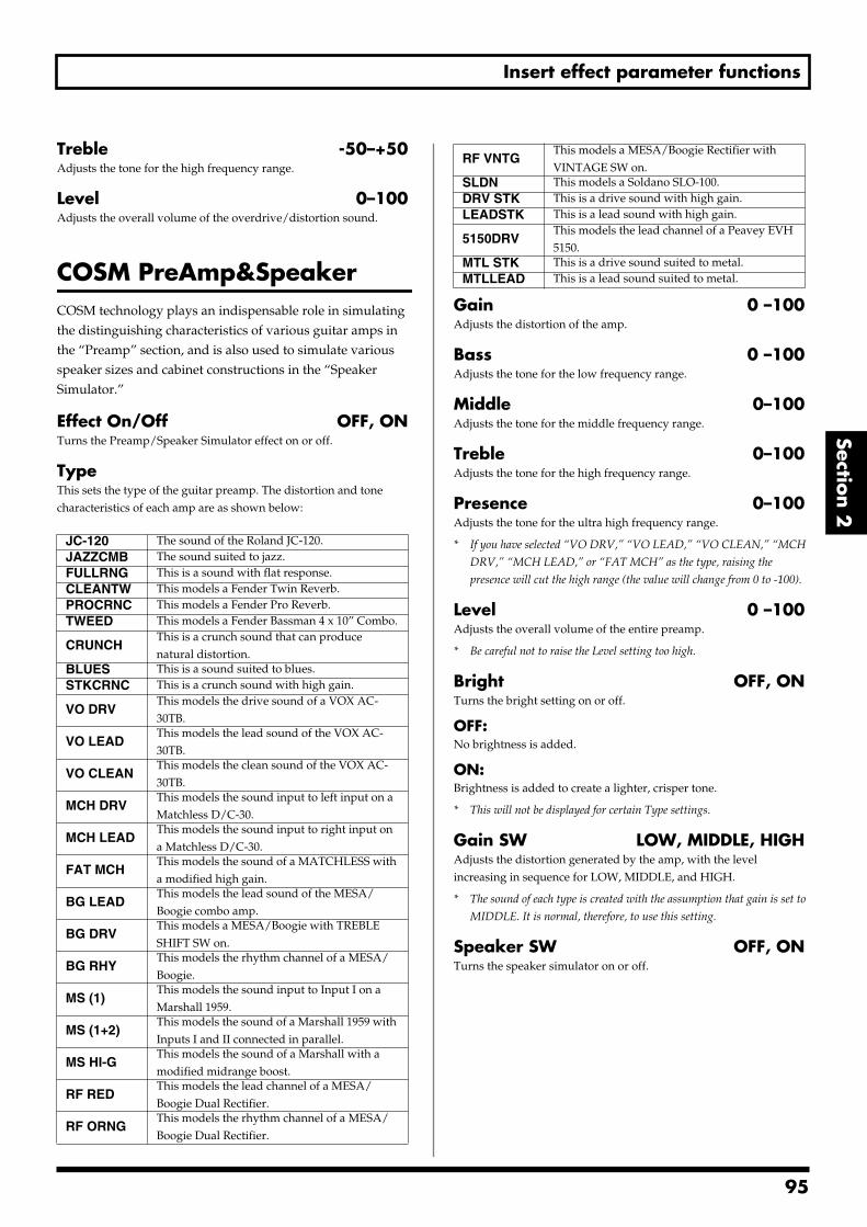
Insert effect parameter functions
Section 2
Treble -50–+50Adjusts the tone for the high frequency range.
Level 0–100Adjusts the overall volume of the overdrive/distortion sound.
COSM PreAmp&SpeakerCOSM technology plays an indispensable role in simulating the distinguishing characteristics of various guitar amps in the “Preamp” section, and is also used to simulate various speaker sizes and cabinet constructions in the “Speaker Simulator.”
Effect On/Off OFF, ONTurns the Preamp/Speaker Simulator effect on or off.
TypeThis sets the type of the guitar preamp. The distortion and tone characteristics of each amp are as shown below:
Gain 0 –100Adjusts the distortion of the amp.
Bass 0 –100Adjusts the tone for the low frequency range.
Middle 0–100Adjusts the tone for the middle frequency range.
Treble 0–100Adjusts the tone for the high frequency range.
Presence 0–100Adjusts the tone for the ultra high frequency range.
* If you have selected “VO DRV,” “VO LEAD,” “VO CLEAN,” “MCH
DRV,” “MCH LEAD,” or “FAT MCH” as the type, raising the
presence will cut the high range (the value will change from 0 to -100).
Level 0 –100Adjusts the overall volume of the entire preamp.
* Be careful not to raise the Level setting too high.
Bright OFF, ONTurns the bright setting on or off.
OFF:No brightness is added.
ON:Brightness is added to create a lighter, crisper tone.
* This will not be displayed for certain Type settings.
Gain SW LOW, MIDDLE, HIGHAdjusts the distortion generated by the amp, with the level increasing in sequence for LOW, MIDDLE, and HIGH.
* The sound of each type is created with the assumption that gain is set to
MIDDLE. It is normal, therefore, to use this setting.
Speaker SW OFF, ONTurns the speaker simulator on or off.
JC-120 The sound of the Roland JC-120.JAZZCMB The sound suited to jazz.FULLRNG This is a sound with flat response.CLEANTW This models a Fender Twin Reverb.PROCRNC This models a Fender Pro Reverb.TWEED This models a Fender Bassman 4 x 10” Combo.
CRUNCHThis is a crunch sound that can produce natural distortion.
BLUES This is a sound suited to blues.STKCRNC This is a crunch sound with high gain.
VO DRVThis models the drive sound of a VOX AC-30TB.
VO LEADThis models the lead sound of the VOX AC-30TB.
VO CLEANThis models the clean sound of the VOX AC-30TB.
MCH DRVThis models the sound input to left input on a Matchless D/C-30.
MCH LEADThis models the sound input to right input on a Matchless D/C-30.
FAT MCHThis models the sound of a MATCHLESS with a modified high gain.
BG LEADThis models the lead sound of the MESA/Boogie combo amp.
BG DRVThis models a MESA/Boogie with TREBLE SHIFT SW on.
BG RHYThis models the rhythm channel of a MESA/Boogie.
MS (1)This models the sound input to Input I on a Marshall 1959.
MS (1+2)This models the sound of a Marshall 1959 with Inputs I and II connected in parallel.
MS HI-GThis models the sound of a Marshall with a modified midrange boost.
RF REDThis models the lead channel of a MESA/Boogie Dual Rectifier.
RF ORNGThis models the rhythm channel of a MESA/Boogie Dual Rectifier.
RF VNTGThis models a MESA/Boogie Rectifier with VINTAGE SW on.
SLDN This models a Soldano SLO-100.DRV STK This is a drive sound with high gain.LEADSTK This is a lead sound with high gain.
5150DRVThis models the lead channel of a Peavey EVH 5150.
MTL STK This is a drive sound suited to metal.MTLLEAD This is a lead sound suited to metal.
95
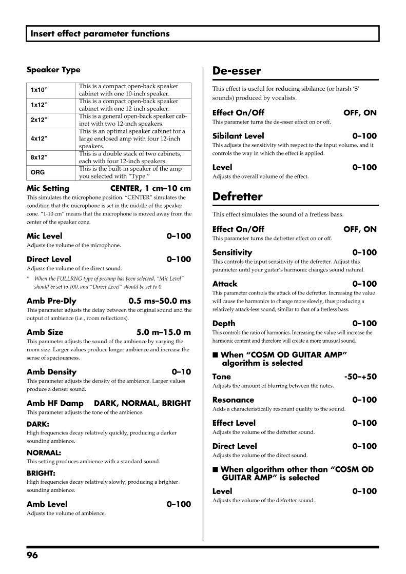
Insert effect parameter functions
Speaker Type
Mic Setting CENTER, 1 cm–10 cmThis simulates the microphone position. “CENTER” simulates the condition that the microphone is set in the middle of the speaker cone. “1-10 cm” means that the microphone is moved away from the center of the speaker cone.
Mic Level 0–100Adjusts the volume of the microphone.
Direct Level 0–100Adjusts the volume of the direct sound.
* When the FULLRNG type of preamp has been selected, “Mic Level”
should be set to 100, and “Direct Level” should be set to 0.
Amb Pre-Dly 0.5 ms–50.0 msThis parameter adjusts the delay between the original sound and the output of ambience (i.e., room reflections).
Amb Size 5.0 m–15.0 mThis parameter adjusts the sound of the ambience by varying the room size. Larger values produce longer ambience and increase the sense of spaciousness.
Amb Density 0–10This parameter adjusts the density of the ambience. Larger values produce a denser sound.
Amb HF Damp DARK, NORMAL, BRIGHTThis parameter adjusts the tone of the ambience.
DARK:High frequencies decay relatively quickly, producing a darker sounding ambience.
NORMAL:This setting produces ambience with a standard sound.
BRIGHT:High frequencies decay relatively slowly, producing a brighter sounding ambience.
Amb Level 0–100Adjusts the volume of ambience.
De-esserThis effect is useful for reducing sibilance (or harsh ‘S’ sounds) produced by vocalists.
Effect On/Off OFF, ONThis parameter turns the de-esser effect on or off.
Sibilant Level 0–100This adjusts the sensitivity with respect to the input volume, and it controls the way in which the effect is applied.
Level 0–100Adjusts the overall volume of the effect.
DefretterThis effect simulates the sound of a fretless bass.
Effect On/Off OFF, ONThis parameter turns the defretter effect on or off.
Sensitivity 0–100This controls the input sensitivity of the defretter. Adjust this parameter until your guitar’s harmonic changes sound natural.
Attack 0–100This parameter controls the attack of the defretter. Increasing the value will cause the harmonics to change more slowly, thus producing a relatively attack-less sound, similar to that of a fretless bass.
Depth 0–100This controls the ratio of harmonics. Increasing the value will increase the harmonic content and therefore will create a more unusual sound.
When “COSM OD GUITAR AMP” algorithm is selected
Tone -50–+50Adjusts the amount of blurring between the notes.
Resonance 0–100Adds a characteristically resonant quality to the sound.
Effect Level 0–100Adjusts the volume of the defretter sound.
Direct Level 0–100Adjusts the volume of the direct sound.
When algorithm other than “COSM OD GUITAR AMP” is selected
Level 0–100Adjusts the volume of the defretter sound.
1x10”This is a compact open-back speaker cabinet with one 10-inch speaker.
1x12”This is a compact open-back speaker cabinet with one 12-inch speaker.
2x12”This is a general open-back speaker cab-inet with two 12-inch speakers.
4x12”This is an optimal speaker cabinet for a large enclosed amp with four 12-inch speakers.
8x12”This is a double stack of two cabinets, each with four 12-inch speakers.
ORGThis is the built-in speaker of the amp you selected with “Type.”
96
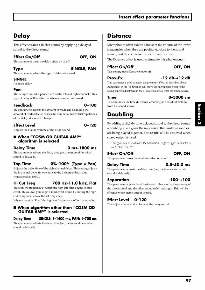
Insert effect parameter functions
Section 2
DelayThis effect creates a thicker sound by applying a delayed sound to the direct sound.
Effect On/Off OFF, ONThis parameter turns the delay effect on or off.
Type SINGLE, PANThis parameter selects the type of delay to be used.
SINGLE:A simple delay.
Pan:The delayed sound is panned across the left and right channels. This type of delay will be effective when stereo output is used.
Feedback 0–100This parameter adjusts the amount of feedback. Changing the amount of feedback also causes the number of individual repetitions of the delayed sound to change.
Effect Level 0–120Adjusts the overall volume of the delay sound.
When “COSM OD GUITAR AMP” algorithm is selected
Delay Time 0 ms–1800 msThis parameter adjusts the delay time (i.e., the interval for which sound is delayed).
Tap Time 0%–100% (Type = Pan)Adjusts the delay time of the right channel delay. This setting adjusts the R channel delay time relative to the L channel delay time (considered as 100%).
Hi Cut Freq 700 Hz–11.0 kHz, FlatThis sets the frequency at which the high cut filter begins to take effect. This allows you to get a mild effect sound by cutting the high-end component above the set frequency.
When it is set to “Flat,” the high cut frequency is off or has no effect.
When algorithm other than “COSM OD GUITAR AMP” is selected
Delay Time SINGLE: 1–1400 ms, PAN: 1–700 msThis parameter adjusts the delay time (i.e., the interval over which sound is delayed).
DistanceMicrophones often exhibit a boost in the volume of the lower frequencies when they are positioned close to the sound source, and this is referred to as proximity effect.
The Distance effect is used to simulate this phenomenon.
Effect On/Off OFF, ONThis setting turns Distance on or off.
Prox.Fx -12 dB–+12 dBThis parameter is used to adjust the proximity effect, as described above. Adjustment in the [+] direction will move the microphone closer to the sound source; adjustment in the [-] direction, away from the sound source.
Time 0–3000 cmThis simulates the time difference occurring as a result of distance from the sound source.
DoublingBy adding a slightly time-delayed sound to the direct sound, a doubling effect gives the impression that multiple sources are being played together. Best results will be achieved when stereo output is used.
* This effect can be used when the Modulation “Effect Type” parameter is
set to “DOUBL’N.”
Effect On/Off OFF, ONThis parameter turns the doubling effect on or off.
Delay Time 0.5–50.0 msThis parameter adjusts the delay time (i.e., the interval for which sound is delayed).
Separation -100–+100This parameter adjusts the diffusion—in other words, the panning of the direct sound and the effect sound to left and right. This will be effective when stereo output is used.
Effect Level 0–120This adjusts the overall volume of the delay sound.
97
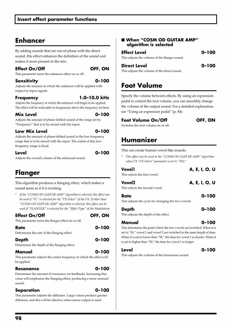
Insert effect parameter functions
EnhancerBy adding sounds that are out-of-phase with the direct sound, this effect enhances the definition of the sound and makes it more present in the mix.
Effect On/Off OFF, ONThis parameter turns the enhancer effect on or off.
Sensitivity 0–100Adjusts the manner in which the enhancer will be applied with respect to input signals.
Frequency 1.0–10.0 kHzAdjusts the frequency at which the enhancer will begin to be applied. The effect will be noticeable in frequencies above the frequency set here.
Mix Level 0–100Adjusts the amount of phase-shifted sound of the range set by “Frequency” that is to be mixed with the input.
Low Mix Level 0–100Adjusts the amount of phase-shifted sound in the low-frequency range that is to be mixed with the input. The extent of this low-frequency range is fixed.
Level 0–100Adjusts the overall volume of the enhanced sound.
FlangerThis algorithm produces a flanging effect, which makes a sound seem as if it is twisting.
* If the “COSM OD GUITAR AMP” algorithm is selected, this effect can
be used if “FL” is selected for the “FX Select” of the FX. If other than
“COSM OD GUITAR AMP” algorithm is selected, this effect can be
used if “FLANGER” is selected for the “Effect Type” of the Modulation.
Effect On/Off OFF, ONThis parameter turns the flanger effect on or off.
Rate 0–100Determines the rate of the flanging effect.
Depth 0–100Determines the depth of the flanging effect.
Manual 0–100This parameter adjusts the center frequency at which the effect will be applied.
Resonance 0–100Determines the amount of resonance (or feedback). Increasing this value will emphasize the flanging effect, producing a more unusual sound.
Separation 0–100This parameter adjusts the diffusion. Large values produce greater diffusion, and this will be effective when stereo output is used.
When “COSM OD GUITAR AMP” algorithm is selected
Effect Level 0–100This adjusts the volume of the flanger sound.
Direct Level 0–100This adjusts the volume of the direct sound.
Foot VolumeSpecify the volume between effects. By using an expression pedal to control the foot volume, you can smoothly change the volume of the output sound. For a detailed explanation, see “Using an expression pedal” (p. 84).
Foot Volume On/Off OFF, ONSwitches the foot volume on or off.
HumanizerThis can create human vowel-like sounds.
* This effect can be used in the “COSM OD GUITAR AMP” algorithm
when FX “FX Select” parameter is set to “HU.”
Vowel1 A, E, I, O, UThis selects the first vowel.
Vowel2 A, E, I, O, UThis selects the second vowel.
Rate 0–100This adjusts the cycle for changing the two vowels.
Depth 0–100This adjusts the depth of the effect.
Manual 0–100This determines the point where the two vowels are switched. When it is set to “50,” vowel 1 and vowel 2 are switched in the same length of time. When it is set to lower than “50,” the time for vowel 1 is shorter. When it is set to higher than “50,” the time for vowel 1 is longer.
Level 0–100This adjusts the volume of the humanizer sound.
98
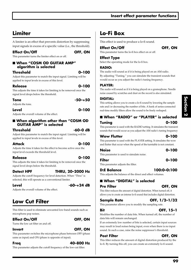
Insert effect parameter functions
Section 2
LimiterA limiter is an effect that prevents distortion by suppressing input signals in excess of a specific value (i.e., the threshold).
Effect On/Off OFF, ONThis parameter turns the limiter effect on or off.
When “COSM OD GUITAR AMP” algorithm is selected
Threshold 0–100Adjust this parameter to match the input signal. Limiting will be applied to input levels in excess of this level.
Release 0–100This adjusts the time it takes for limiting to be removed once the signal level drops below the threshold.
Tone -50–+50Adjusts the tone.
Level 0–100Adjusts the overall volume of the effect.
When algorithm other than “COSM OD GUITAR AMP” is selected
Threshold -60–0 dBAdjust this parameter to match the input signal. Limiting will be applied to input levels in excess of this level.
Attack 0–100Adjusts the time it takes for the effect to become active once the input level exceeds the threshold level.
Release 0–100This adjusts the time it takes for limiting to be removed once the signal level drops below the threshold.
Detect HPF THRU, 20–2000 HzAdjusts the cutoff frequency for level detection. When “Thru” is selected, this will operate as a conventional limiter.
Level -60–+24 dBAdjusts the overall volume of the effect.
Low Cut FilterThis filter is used to eliminate unwanted low-band sounds such as microphone pop noises.
Effect On/Off OFF, ONTurns the low cat filter on and off.
Invert OFF, ONThis parameter switches the microphone phase between OFF (phase same as input) and ON (phase is opposite of input).
Freq 40–800 HzThis parameter adjusts the cutoff frequency of the low-cut filter.
Lo-Fi BoxThis effect is used to produce a lo-fi sound.
Effect On/Off OFF, ONThis parameter turns the lo-fi box effect on or off.
Effect TypeSelect the operating mode for the lo-fi box.
RADIO:The audio will sound as if it is being played on an AM radio.
By adjusting “Tuning,” you can simulate the transient sounds that would occur as you adjust the radio’s tuning frequency.
PLAYER:The audio will sound as if it is being played on a gramophone. Needle noise caused by scratches and dust on the record is also simulated.
DIGITAL:This setting allows you to create a lo-fi sound by lowering the sample rate and/or decreasing the number of bits. A bank of series-connected real-time modify filters allow the sound to be freely reshaped.
When “RADIO” or “PLAYER” is selectedTuning 0–100This parameter is used with the RADIO setting. It simulates the transient sounds that would occur as you adjust the AM radio’s tuning frequency
Wow Flutter 0–100This parameter is used with the PLAYER setting. It simulates the wow and flutter that occur when the speed of the turntable is not constant.
Noise 0–100This parameter is used to simulate noise.
Filter 0–100This parameter adjusts the filter.
D:E Balance 100:0–0:100This adjusts the balance of the direct and effect volumes.
When “DIGITAL” is selectedPre Filter OFF, ONThis filter reduces the amount of digital distortion. When turned off, it allows you to create an intense lo-fi sound that includes digital distortion.
Sample Rate OFF, 1/2–1/32This parameter allows you to modify the sampling rate.
Bit OFF, 15–1Modifies the number of data bits. When turned off, the number of data bits will remain unchanged.
If an extremely low number of bits is selected, certain input sources may result in loud noises being input, even when there is no input sound. In such a case, raise the noise suppressor’s threshold.
Post Filter OFF, ONThis filter reduces the amount of digital distortion produced by the lo-fi. By turning this off, you can create an extremely lo-fi sound.
99
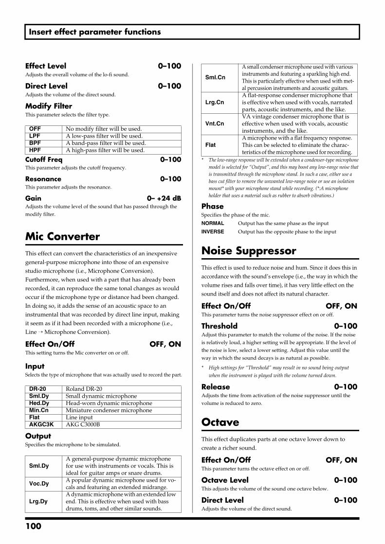
Insert effect parameter functions
Effect Level 0–100Adjusts the overall volume of the lo-fi sound.
Direct Level 0–100Adjusts the volume of the direct sound.
Modify FilterThis parameter selects the filter type.
Cutoff Freq 0–100This parameter adjusts the cutoff frequency.
Resonance 0–100This parameter adjusts the resonance.
Gain 0– +24 dBAdjusts the volume level of the sound that has passed through the modify filter.
Mic ConverterThis effect can convert the characteristics of an inexpensive general-purpose microphone into those of an expensive studio microphone (i.e., Microphone Conversion). Furthermore, when used with a part that has already been recorded, it can reproduce the same tonal changes as would occur if the microphone type or distance had been changed. In doing so, it adds the sense of an acoustic space to an instrumental that was recorded by direct line input, making it seem as if it had been recorded with a microphone (i.e., Line → Microphone Conversion).
Effect On/Off OFF, ONThis setting turns the Mic converter on or off.
InputSelects the type of microphone that was actually used to record the part.
OutputSpecifies the microphone to be simulated.
* The low-range response will be extended when a condenser-type microphone model is selected for “Output”, and this may boost any low-range noise that is transmitted through the microphone stand. In such a case, either use a bass cut filter to remove the unwanted low-range noise or use an isolation mount* with your microphone stand while recording. (*:A microphone holder that uses a material such as rubber to absorb vibrations.)
PhaseSpecifies the phase of the mic.
NORMAL Output has the same phase as the input
INVERSE Output has the opposite phase to the input
Noise SuppressorThis effect is used to reduce noise and hum. Since it does this in accordance with the sound’s envelope (i.e., the way in which the volume rises and falls over time), it has very little effect on the sound itself and does not affect its natural character.
Effect On/Off OFF, ONThis parameter turns the noise suppressor effect on or off.
Threshold 0–100Adjust this parameter to match the volume of the noise. If the noise is relatively loud, a higher setting will be appropriate. If the level of the noise is low, select a lower setting. Adjust this value until the way in which the sound decays is as natural as possible.
* High settings for “Threshold” may result in no sound being output
when the instrument is played with the volume turned down.
Release 0–100Adjusts the time from activation of the noise suppressor until the volume is reduced to zero.
OctaveThis effect duplicates parts at one octave lower down to create a richer sound.
Effect On/Off OFF, ONThis parameter turns the octave effect on or off.
Octave Level 0–100This adjusts the volume of the sound one octave below.
Direct Level 0–100Adjusts the volume of the direct sound.
OFF No modify filter will be used.LPF A low-pass filter will be used.BPF A band-pass filter will be used.HPF A high-pass filter will be used.
DR-20 Roland DR-20Sml.Dy Small dynamic microphoneHed.Dy Head-worn dynamic microphoneMin.Cn Miniature condenser microphoneFlat Line inputAKGC3K AKG C3000B
Sml.DyA general-purpose dynamic microphone for use with instruments or vocals. This is ideal for guitar amps or snare drums.
Voc.DyA popular dynamic microphone used for vo-cals and featuring an extended midrange.
Lrg.DyA dynamic microphone with an extended low end. This is effective when used with bass drums, toms, and other similar sounds.
Sml.Cn
A small condenser microphone used with various instruments and featuring a sparkling high end. This is particularly effective when used with met-al percussion instruments and acoustic guitars.
Lrg.CnA flat-response condenser microphone that is effective when used with vocals, narrated parts, acoustic instruments, and the like.
Vnt.CnVA vintage condenser microphone that is effective when used with vocals, acoustic instruments, and the like.
FlatA microphone with a flat frequency response. This can be selected to eliminate the charac-teristics of the microphone used for recording.
100
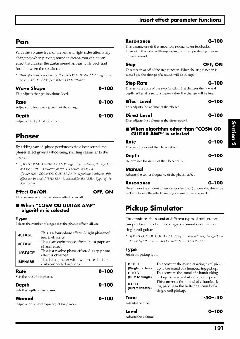
Insert effect parameter functions
Section 2
PanWith the volume level of the left and right sides alternately changing, when playing sound in stereo, you can get an effect that makes the guitar sound appear to fly back and forth between the speakers.
* This effect can be used in the “COSM OD GUITAR AMP” algorithm
when FX “FX Select” parameter is set to “PAN.”
Wave Shape 0–100This adjusts changes in volume level.
Rate 0–100Adjusts the frequency (speed) of the change.
Depth 0–100Adjusts the depth of the effect.
PhaserBy adding varied-phase portions to the direct sound, the phaser effect gives a whooshing, swirling character to the sound.
* If the “COSM OD GUITAR AMP” algorithm is selected, this effect can
be used if “PH” is selected for the “FX Select” of the FX.
If other than “COSM OD GUITAR AMP” algorithm is selected, this
effect can be used if “PHASER” is selected for the “Effect Type” of the
Modulation.
Effect On/Off OFF, ONThis parameter turns the phaser effect on or off.
When “COSM OD GUITAR AMP” algorithm is selected
TypeSelects the number of stages that the phaser effect will use.
Rate 0–100Sets the rate of the phaser.
Depth 0–100Sets the depth of the phaser.
Manual 0–100Adjusts the center frequency of the phaser.
Resonance 0–100This parameter sets the amount of resonance (or feedback). Increasing the value will emphasize the effect, producing a more unusual sound.
Step OFF, ONThis sets on or off of the step function. When the step function is turned on, the change of a sound will be in steps.
Step Rate 0–100This sets the cycle of the step function that changes the rate and depth. When it is set to a higher value, the change will be finer.
Effect Level 0–100This adjusts the volume of the phaser.
Direct Level 0–100This adjusts the volume of the direct sound.
When algorithm other than “COSM OD GUITAR AMP” is selected
Rate 0–100This sets the rate of the Phaser effect.
Depth 0–100Determines the depth of the Phaser effect.
Manual 0–100Adjusts the center frequency of the phaser effect.
Resonance 0–100Determines the amount of resonance (feedback). Increasing the value will emphasize the effect, creating a more unusual sound.
Pickup SimulatorThis produces the sound of different types of pickup. You can produce thick humbucking-style sounds even with a single-coil guitar.
* If the “COSM OD GUITAR AMP” algorithm is selected, this effect can
be used if “PIC” is selected for the “FX Select” of the FX.
TypeSelect the pickup type.
Tone -50–+50Adjusts the tone.
Level 0–100Adjusts the volume.
4STAGEThis is a four-phase effect. A light phaser ef-fect is obtained.
8STAGEThis is an eight-phase effect. It is a popular phaser effect.
12STAGEThis is a twelve-phase effect. A deep phase effect is obtained.
BIPHASEThis is the phaser with two phase shift cir-cuits connected in series. S TO H
(Single to Hum)This converts the sound of a single coil pick-up to the sound of a humbucking pickup.
H TO S(Hum to Single)
This converts the sound of a humbucking pickup to the sound of a single coil pickup.
H TO HF(Hum to Half-tone)
This converts the sound of a humbuck-ing pickup to the half-tone sound of a single-coil pickup.
101
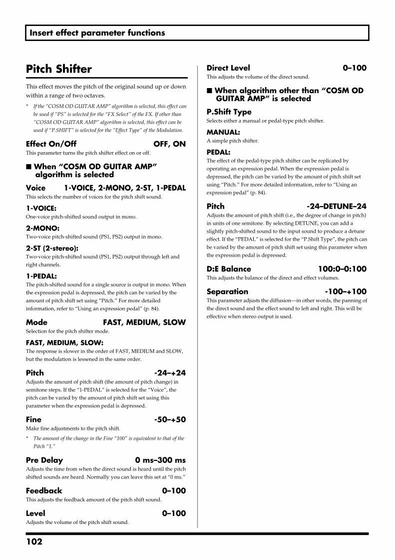
Insert effect parameter functions
Pitch ShifterThis effect moves the pitch of the original sound up or down within a range of two octaves.
* If the “COSM OD GUITAR AMP” algorithm is selected, this effect can
be used if “PS” is selected for the “FX Select” of the FX. If other than
“COSM OD GUITAR AMP” algorithm is selected, this effect can be
used if “P.SHIFT” is selected for the “Effect Type” of the Modulation.
Effect On/Off OFF, ONThis parameter turns the pitch shifter effect on or off.
When “COSM OD GUITAR AMP” algorithm is selected
Voice 1-VOICE, 2-MONO, 2-ST, 1-PEDALThis selects the number of voices for the pitch shift sound.
1-VOICE:One-voice pitch-shifted sound output in mono.
2-MONO:Two-voice pitch-shifted sound (PS1, PS2) output in mono.
2-ST (2-stereo):Two-voice pitch-shifted sound (PS1, PS2) output through left and right channels.
1-PEDAL:The pitch-shifted sound for a single source is output in mono. When the expression pedal is depressed, the pitch can be varied by the amount of pitch shift set using “Pitch.” For more detailed information, refer to “Using an expression pedal” (p. 84).
Mode FAST, MEDIUM, SLOWSelection for the pitch shifter mode.
FAST, MEDIUM, SLOW:The response is slower in the order of FAST, MEDIUM and SLOW, but the modulation is lessened in the same order.
Pitch -24–+24Adjusts the amount of pitch shift (the amount of pitch change) in semitone steps. If the “1-PEDAL” is selected for the “Voice”, the pitch can be varied by the amount of pitch shift set using this parameter when the expression pedal is depressed.
Fine -50–+50Make fine adjustments to the pitch shift.
* The amount of the change in the Fine “100” is equivalent to that of the
Pitch “1.”
Pre Delay 0 ms–300 msAdjusts the time from when the direct sound is heard until the pitch shifted sounds are heard. Normally you can leave this set at “0 ms.”
Feedback 0–100This adjusts the feedback amount of the pitch shift sound.
Level 0–100Adjusts the volume of the pitch shift sound.
Direct Level 0–100This adjusts the volume of the direct sound.
When algorithm other than “COSM OD GUITAR AMP” is selected
P.Shift TypeSelects either a manual or pedal-type pitch shifter.
MANUAL:A simple pitch shifter.
PEDAL:The effect of the pedal-type pitch shifter can be replicated by operating an expression pedal. When the expression pedal is depressed, the pitch can be varied by the amount of pitch shift set using “Pitch.” For more detailed information, refer to “Using an expression pedal” (p. 84).
Pitch -24–DETUNE–24Adjusts the amount of pitch shift (i.e., the degree of change in pitch) in units of one semitone. By selecting DETUNE, you can add a slightly pitch-shifted sound to the input sound to produce a detune effect. If the “PEDAL” is selected for the “P.Shift Type”, the pitch can be varied by the amount of pitch shift set using this parameter when the expression pedal is depressed.
D:E Balance 100:0–0:100This adjusts the balance of the direct and effect volumes.
Separation -100–+100This parameter adjusts the diffusion—in other words, the panning of the direct sound and the effect sound to left and right. This will be effective when stereo output is used.
102
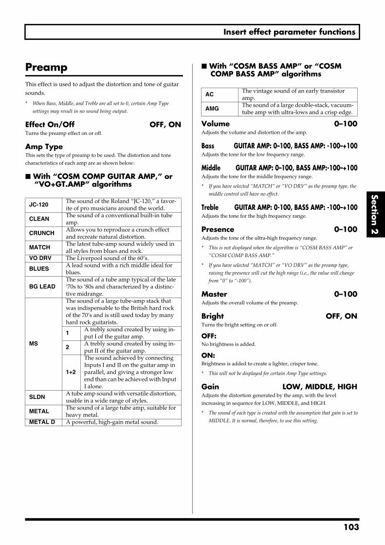
Insert effect parameter functions
Section 2
PreampThis effect is used to adjust the distortion and tone of guitar sounds.
* When Bass, Middle, and Treble are all set to 0, certain Amp Type
settings may result in no sound being output.
Effect On/Off OFF, ONTurns the preamp effect on or off.
Amp TypeThis sets the type of preamp to be used. The distortion and tone characteristics of each amp are as shown below:
With “COSM COMP GUITAR AMP,” or “VO+GT.AMP” algorithms
With “COSM BASS AMP” or “COSM COMP BASS AMP” algorithms
Volume 0–100Adjusts the volume and distortion of the amp.
Bass GUITAR AMP: 0–100, BASS AMP: -100–+100Adjusts the tone for the low frequency range.
Middle GUITAR AMP: 0–100, BASS AMP:-100–+100Adjusts the tone for the middle frequency range.
* If you have selected “MATCH” or “VO DRV” as the preamp type, the
middle control will have no effect.
Treble GUITAR AMP: 0-100, BASS AMP: -100–+100Adjusts the tone for the high frequency range.
Presence 0–100Adjusts the tone of the ultra-high frequency range.
* This is not displayed when the algorithm is “COSM BASS AMP” or
“COSM COMP BASS AMP.”
* If you have selected “MATCH” or “VO DRV” as the preamp type,
raising the presence will cut the high range (i.e., the value will change
from “0” to “-100”).
Master 0–100Adjusts the overall volume of the preamp.
Bright OFF, ONTurns the bright setting on or off.
OFF:No brightness is added.
ON:Brightness is added to create a lighter, crisper tone.
* This will not be displayed for certain Amp Type settings.
Gain LOW, MIDDLE, HIGHAdjusts the distortion generated by the amp, with the level increasing in sequence for LOW, MIDDLE, and HIGH.
* The sound of each type is created with the assumption that gain is set to
MIDDLE. It is normal, therefore, to use this setting.
JC-120The sound of the Roland “JC-120,” a favor-ite of pro musicians around the world.
CLEANThe sound of a conventional built-in tube amp.
CRUNCHAllows you to reproduce a crunch effect and recreate natural distortion.
MATCHThe latest tube-amp sound widely used in all styles from blues and rock.
VO DRV The Liverpool sound of the 60’s.
BLUESA lead sound with a rich middle ideal for blues.
BG LEADThe sound of a tube amp typical of the late ‘70s to ‘80s and characterized by a distinc-tive midrange.
MS
The sound of a large tube-amp stack that was indispensable to the British hard rock of the 70’s and is still used today by many hard rock guitarists.
1A trebly sound created by using in-put I of the guitar amp.
2A trebly sound created by using in-put II of the guitar amp.
1+2
The sound achieved by connecting Inputs I and II on the guitar amp in parallel, and giving a stronger low end than can be achieved with Input I alone.
SLDNA tube amp sound with versatile distortion, usable in a wide range of styles.
METALThe sound of a large tube amp, suitable for heavy metal.
METAL D A powerful, high-gain metal sound.
ACThe vintage sound of an early transistor amp.
AMGThe sound of a large double-stack, vacuum-tube amp with ultra-lows and a crisp edge.
103
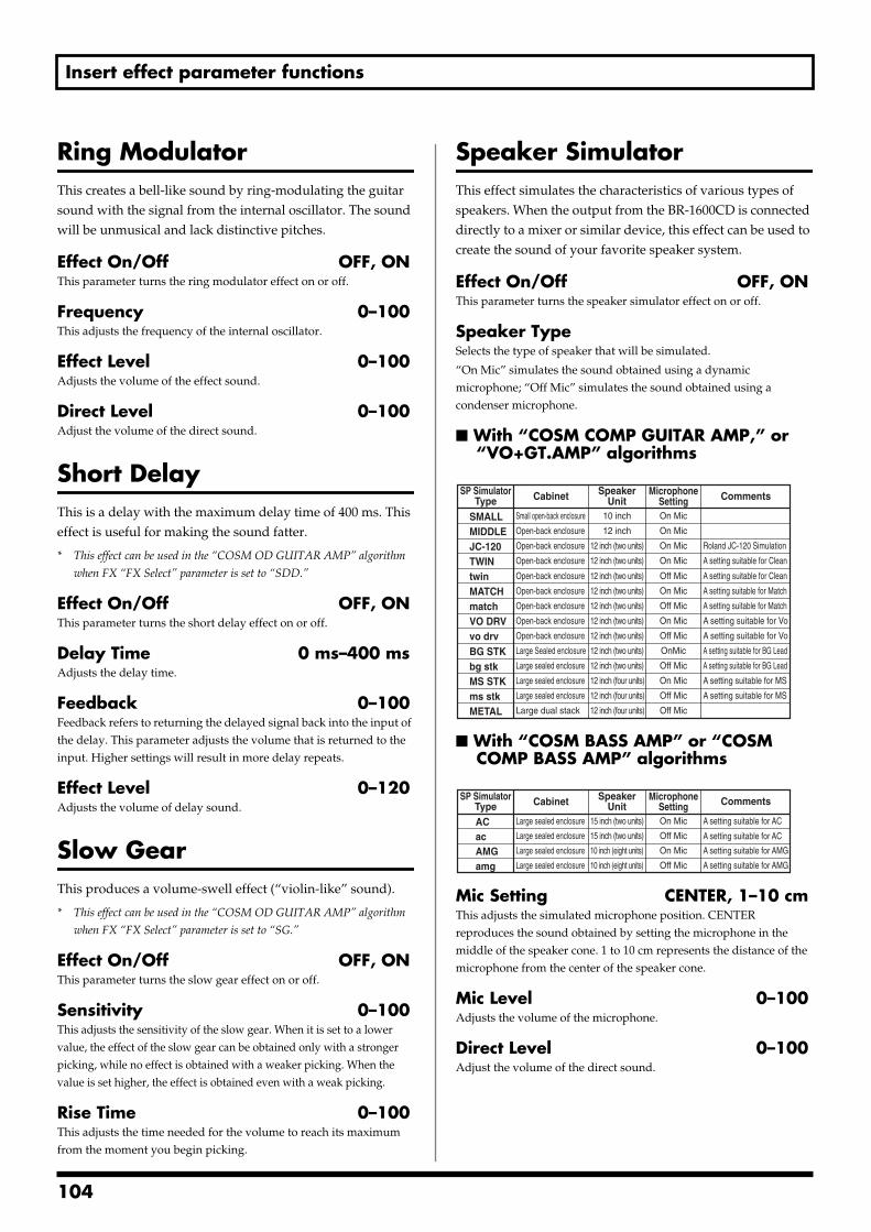
Insert effect parameter functions
Ring ModulatorThis creates a bell-like sound by ring-modulating the guitar sound with the signal from the internal oscillator. The sound will be unmusical and lack distinctive pitches.
Effect On/Off OFF, ONThis parameter turns the ring modulator effect on or off.
Frequency 0–100This adjusts the frequency of the internal oscillator.
Effect Level 0–100Adjusts the volume of the effect sound.
Direct Level 0–100Adjust the volume of the direct sound.
Short DelayThis is a delay with the maximum delay time of 400 ms. This effect is useful for making the sound fatter.
* This effect can be used in the “COSM OD GUITAR AMP” algorithm
when FX “FX Select” parameter is set to “SDD.”
Effect On/Off OFF, ONThis parameter turns the short delay effect on or off.
Delay Time 0 ms–400 msAdjusts the delay time.
Feedback 0–100Feedback refers to returning the delayed signal back into the input of the delay. This parameter adjusts the volume that is returned to the input. Higher settings will result in more delay repeats.
Effect Level 0–120Adjusts the volume of delay sound.
Slow GearThis produces a volume-swell effect (“violin-like” sound).
* This effect can be used in the “COSM OD GUITAR AMP” algorithm
when FX “FX Select” parameter is set to “SG.”
Effect On/Off OFF, ONThis parameter turns the slow gear effect on or off.
Sensitivity 0–100This adjusts the sensitivity of the slow gear. When it is set to a lower value, the effect of the slow gear can be obtained only with a stronger picking, while no effect is obtained with a weaker picking. When the value is set higher, the effect is obtained even with a weak picking.
Rise Time 0–100This adjusts the time needed for the volume to reach its maximum from the moment you begin picking.
Speaker SimulatorThis effect simulates the characteristics of various types of speakers. When the output from the BR-1600CD is connected directly to a mixer or similar device, this effect can be used to create the sound of your favorite speaker system.
Effect On/Off OFF, ONThis parameter turns the speaker simulator effect on or off.
Speaker TypeSelects the type of speaker that will be simulated.
“On Mic” simulates the sound obtained using a dynamic microphone; “Off Mic” simulates the sound obtained using a condenser microphone.
With “COSM COMP GUITAR AMP,” or “VO+GT.AMP” algorithms
fig.S03-01
With “COSM BASS AMP” or “COSM COMP BASS AMP” algorithms
fig.S03-02
Mic Setting CENTER, 1–10 cmThis adjusts the simulated microphone position. CENTER reproduces the sound obtained by setting the microphone in the middle of the speaker cone. 1 to 10 cm represents the distance of the microphone from the center of the speaker cone.
Mic Level 0–100Adjusts the volume of the microphone.
Direct Level 0–100Adjust the volume of the direct sound.
CommentsCabinet
A setting suitable for Clean
On Mic
Roland JC-120 Simulation
10 inch
12 inch
12 inch (two units)
12 inch (four units)
Small open-back enclosure
Open-back enclosure
Large Sealed enclosure
Large sealed enclosure
Large dual stack
On Mic
On Mic
On Mic
Off Mic
On Mic
Off Mic
OnMic
Off Mic
On Mic
Off Mic
Off Mic
Open-back enclosure
Open-back enclosure
Open-back enclosure
Open-back enclosure
Open-back enclosure
Large sealed enclosure
Large sealed enclosure
12 inch (two units)
12 inch (two units)
12 inch (two units)
12 inch (two units)
12 inch (two units)
12 inch (two units)
12 inch (four units)
12 inch (four units)
A setting suitable for Clean
A setting suitable for Match
A setting suitable for Match
A setting suitable for BG Lead
A setting suitable for BG Lead
SMALLMIDDLEJC-120TWINtwinMATCHmatch
BG STKbg stkMS STKms stkMETAL
A setting suitable for MS
A setting suitable for MS
On Mic
Off Mic
Open-back enclosure
Open-back enclosure
12 inch (two units)
12 inch (two units)
A setting suitable for Vo
A setting suitable for Vo
VO DRVvo drv
MicrophoneSetting
SpeakerUnit
SP SimulatorType
CommentsMicrophoneSetting
SpeakerUnit
SP SimulatorType Cabinet
A setting suitable for AMG
A setting suitable for AMG
On Mic15 inch (two units)
15 inch (two units)
10 inch (eight units)
Large sealed enclosure
Large sealed enclosure Off Mic
On Mic
Off Mic
Large sealed enclosure
Large sealed enclosure 10 inch (eight units)
A setting suitable for AC
A setting suitable for AC
ACacAMGamg
104
Insert effect parameter functions
Section 2
Sub EqualizerThis adjusts the tone as a sub equalizer. A parametric type is adopted for the high-middle and low-middle range.
* This effect can be used in the “COSM OD GUITAR AMP” algorithm
when FX “FX Select” parameter is set to “SEQ.”
Effect On/Off OFF, ONThis parameter turns the sub equalizer effect on or off.
Low Gain -20–+20 dBThis parameter sets the gain (amount of boost or cut) for the bass equalizer.
Low-Mid Gain -20–+20 dBThis parameter sets the gain (amount of boost or cut) for the low-midrange equalizer.
Low-Mid Freq 100 Hz–10.0 kHzThis parameter sets the central frequency for the low-midrange equalizer.
Low-Mid Q 0.5–16This parameter sets the range of change in gain for the frequency set by “Low-Mid Freq.” A larger value results in a narrower range of change.
Hi-Mid Gain -20–+20 dBThis parameter sets the gain (amount of boost or cut) for the high-midrange equalizer.
Hi-Mid Freq 100 Hz–10.0 kHzThis parameter sets the central frequency for the high-midrange equalizer.
Hi-Mid Q 0.5–16This parameter sets the range of change in gain for the frequency set by “Hi-Mid Freq.” A larger value results in a narrower range of change.
High Gain -20–+20 dBThis parameter sets the gain (amount of boost or cut) for the treble equalizer.
Level -20–+20 dBThis parameter adjusts the volume after the equalizer stage.
TremoloTremolo is an effect that creates a cyclic change in volume.
* This effect can be used when “COSM OD GUITAR AMP” algorithm is
selected.
Wave Shape 0–100This adjusts changes in volume level.
Rate 0–100Adjusts the frequency (speed) of the change.
Depth 0–100Adjusts the depth of the effect.
Tremolo/PanTremolo is an effect that creates a cyclic change in volume, and pan moves the stereo position in a cyclic manner between left and right (when stereo output is used).
* This effect can be used when the Modulation “Effect Type” parameter is
set to “TRM/PAN.”
Effect On/Off OFF, ONThis parameter turns the tremolo/pan effect on or off.
ModeThis parameter selects tremolo or pan, and it also selects how the effect will be applied.
TRM-TRI:The volume will change cyclically and smooth changes will be produced.
TRM-SQR:The volume will change cyclically and abrupt changes will be produced.
PAN-TRI:The sound will be moved cyclically between the left and right. Smooth changes will be produced.
PAN-SQR:The sound will be moved cyclically between the left and right. Abrupt changes will be produced.
Rate 0–100Adjust the rate at which the effect will operate.
Depth 0–100Adjusts the depth of the effect.
Uni-VAlthough this resembles a phaser effect, it also provides a unique undulation that you can’t get with a regular phaser.
* This effect can be used in the “COSM OD GUITAR AMP” algorithm
when FX “FX Select” parameter is set to “UV.”
Rate 0–100Adjusts the rate of the Uni-V effect.
Depth 0–100Adjusts the depth of the Uni-V effect.
Level 0–100Adjusts the volume.
105
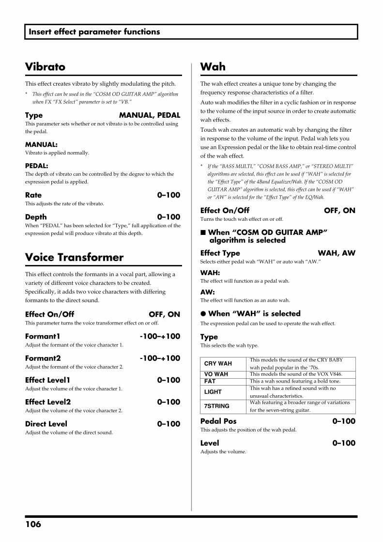
Insert effect parameter functions
VibratoThis effect creates vibrato by slightly modulating the pitch.
* This effect can be used in the “COSM OD GUITAR AMP” algorithm
when FX “FX Select” parameter is set to “VB.”
Type MANUAL, PEDALThis parameter sets whether or not vibrato is to be controlled using the pedal.
MANUAL:Vibrato is applied normally.
PEDAL:The depth of vibrato can be controlled by the degree to which the expression pedal is applied.
Rate 0–100This adjusts the rate of the vibrato.
Depth 0–100When “PEDAL” has been selected for “Type,” full application of the expression pedal will produce vibrato at this depth.
Voice TransformerThis effect controls the formants in a vocal part, allowing a variety of different voice characters to be created. Specifically, it adds two voice characters with differing formants to the direct sound.
Effect On/Off OFF, ONThis parameter turns the voice transformer effect on or off.
Formant1 -100–+100Adjust the formant of the voice character 1.
Formant2 -100–+100Adjust the formant of the voice character 2.
Effect Level1 0–100Adjust the volume of the voice character 1.
Effect Level2 0–100Adjust the volume of the voice character 2.
Direct Level 0–100Adjust the volume of the direct sound.
WahThe wah effect creates a unique tone by changing the frequency response characteristics of a filter.
Auto wah modifies the filter in a cyclic fashion or in response to the volume of the input source in order to create automatic wah effects.
Touch wah creates an automatic wah by changing the filter in response to the volume of the input. Pedal wah lets you use an Expression pedal or the like to obtain real-time control of the wah effect.
* If the “BASS MULTI,” “COSM BASS AMP,” or “STEREO MULTI”
algorithms are selected, this effect can be used if “WAH” is selected for
the “Effect Type” of the 4Band Equalizer/Wah. If the “COSM OD
GUITAR AMP” algorithm is selected, this effect can be used if “WAH”
or “AW” is selected for the “Effect Type” of the EQ/Wah.
Effect On/Off OFF, ONTurns the touch wah effect on or off.
When “COSM OD GUITAR AMP” algorithm is selected
Effect Type WAH, AWSelects either pedal wah “WAH” or auto wah “AW.”
WAH:The effect will function as a pedal wah.
AW:The effect will function as an auto wah.
When “WAH” is selectedThe expression pedal can be used to operate the wah effect.
TypeThis selects the wah type.
Pedal Pos 0–100This adjusts the position of the wah pedal.
Level 0–100Adjusts the volume.
CRY WAHThis models the sound of the CRY BABY wah pedal popular in the `70s.
VO WAH This models the sound of the VOX V846.FAT This a wah sound featuring a bold tone.
LIGHTThis wah has a refined sound with no unusual characteristics.
7STRINGWah featuring a broader range of variations for the seven-string guitar.
106
Insert effect parameter functions
Section 2
When “AW” is selectedThe effect will be applied automatically based on the volume of the performance. Alternatively, it is also possible to apply wah in a cyclic fashion.
Mode LPF, BPFSelection for the wah mode.
LPF:This creates a wah effect over a wide frequency range.
BPF:This creates a wah effect in a narrow frequency range.
Polarity DOWN, UPSelection for the direction in which the filter will change in response to the input.
UP:The frequency of the filter will rise.
DOWN:The frequency of the filter will fall.
Sensitivity 0–100Adjusts the sensitivity of the filter in the direction specified by the polarity setting. Higher values will result in a stronger response. When the setting is 0, the strength of the picking will have no effect.
Frequency 0–100Adjusts the center frequency of the wah effect.
Peak 0–100Adjusts the way in which the wah effect is applied to the area around the center frequency. Lower values will produce a wah effect over a wider area; higher values, a wah effect over a narrower area. When the setting is 50, a standard wah sound will be produced.
* With a value of “50” a standard wah sound will be produced.
Rate 0–100Adjusts the frequency of the auto wah.
Depth 0–100Adjusts the depth of the auto wah effect.
Level 0–100This parameter adjusts the volume.
When algorithm other than “COSM OD GUITAR AMP” is selected
Wah TypeSelects either touch wah “TOUCH” or pedal wah “PEDAL.”
TOUCH:The effect will function as a touch wah.
PEDAL:The effect will function as a pedal wah.
When “TOUCH” is selected
Polarity UP, DOWNSelects the direction in which the filter will change in response to input.
UP:The frequency of the filter will rise.
DOWN:The frequency of the filter will fall.
Sensitivity 0–100Adjusts the sensitivity of the filter in the direction specified by the polarity setting. Higher values will result in a stronger response. When the setting is 0, the strength of the picking will have no effect.
Frequency 0–100Adjusts the center frequency of the wah effect.
Peak 0–100Adjusts the way in which the wah effect applies to the area around the center frequency. Lower values will produce a wah effect over a wide area around the center frequency. Higher values will produce a wah effect in a narrow area around the center frequency. With a value of “50” a standard wah sound will be produced.
Level 0–100This parameter adjusts the volume.
When “PEDAL” is selectedThe effect of the wah pedal can be reproduced by operating an expression pedal.
For a more detailed explanation, see “Using an expression pedal” (p. 84).
Peak 0–100Adjusts the way in which the wah effect is applied to the area around the center frequency. Lower values will produce a wah effect over a wider area; higher values, a wah effect over a narrower area. When the setting is 50, a standard wah sound will be produced.
Level 0–100This parameter adjusts the volume.
107
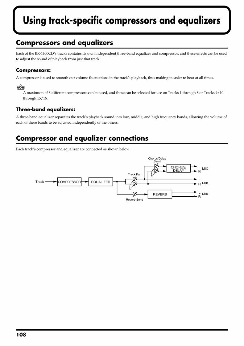
1
Using track-specific compressors and equalizers
Compressors and equalizersEach of the BR-1600CD’s tracks contains its own independent three-band equalizer and compressor, and these effects can be used to adjust the sound of playback from just that track.
Compressors:A compressor is used to smooth out volume fluctuations in the track’s playback, thus making it easier to hear at all times.
A maximum of 8 different compressors can be used, and these can be selected for use on Tracks 1 through 8 or Tracks 9/10 through 15/16.
Three-band equalizers:A three-band equalizer separates the track’s playback sound into low, middle, and high frequency bands, allowing the volume of each of these bands to be adjusted independently of the others.
Compressor and equalizer connectionsEach track’s compressor and equalizer are connected as shown below.fig.32-01
Track
REVERB
CHORUS/DELAY
EQUALIZERCOMPRESSOR
LMIX
MIX
MIX
R
L
R
LR
Chorus/DelaySend
Reverb Send
Track Pan
08
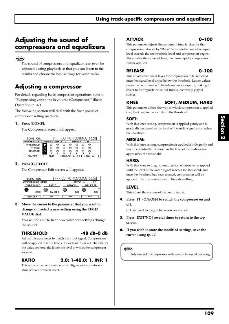
Using track-specific compressors and equalizers
Section 2
Adjusting the sound of compressors and equalizers
The sound of compressors and equalizers can even be adjusted during playback so that you can listen to the results and choose the best settings for your tracks.
Adjusting a compressorFor details regarding basic compressor operations, refer to “Suppressing variations in volume (Compressor)” (Basic Operation; p. 47).
The following section will deal with the finer points of compressor setting methods.
1. Press [COMP].
The Compressor screen will appear.fig.32-05d
2. Press [F2] (EDIT).
The Compressor Edit screen will appear.fig.32-06d
3. Move the cursor to the parameter that you want to change and select a new setting using the TIME/VALUE dial.
You will be able to hear how your new settings change the sound.
THRESHOLD -48 dB–0 dBAdjust this parameter to match the input signal. Compression will be applied to input levels in excess of this level. The smaller the value set here, the lower the level at which the compressor kicks in.
RATIO 2.0: 1–40.0: 1, INF: 1This adjusts the compression ratio. Higher ratios produce a stronger compression effect.
ATTACK 0–100This parameter adjusts the amount of time it takes for the compression ratio set by “Ratio” to be reached once the input level exceeds the set threshold level and compression begins. The smaller the value set here, the more rapidly compression will be applied.
RELEASE 0–100This adjusts the time it takes for compression to be removed once the signal level drops below the threshold. Lower values cause the compression to be released more rapidly, making it easier to distinguish the sound from successively played strings.
KNEE SOFT, MEDIUM, HARDThis parameter affects the way in which compression is applied (i.e., the knee) in the vicinity of the threshold.
SOFT:With this knee setting, compression is applied gently and is gradually increased as the level of the audio signal approaches the threshold.
MEDIUM:With this knee setting, compression is applied a little gently and is a little gradually increased as the level of the audio signal approaches the threshold.
HARD:With this knee setting, no compression whatsoever is applied until the level of the audio signal reaches the threshold, and once the threshold has been crossed, compression will be applied fully in accordance with the ratio setting.
LEVELThis adjust the volume of the compression.
4. Press [F1] (ON/OFF) to switch the compressor on and off.
[F1] is used to toggle between on and off.
5. Press [EXIT/NO] several times to return to the top screen.
6. If you wish to store the modified settings, save the current song (p. 72).
Only one set of compressor settings can be saved per song.
109
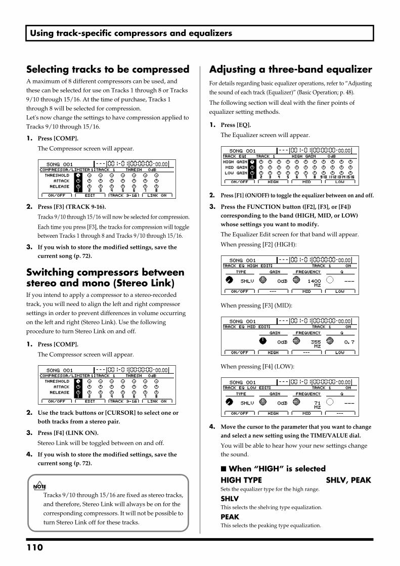
Using track-specific compressors and equalizers
Selecting tracks to be compressedA maximum of 8 different compressors can be used, and these can be selected for use on Tracks 1 through 8 or Tracks 9/10 through 15/16. At the time of purchase, Tracks 1 through 8 will be selected for compression.Let's now change the settings to have compression applied to Tracks 9/10 through 15/16.
1. Press [COMP].
The Compressor screen will appear.fig.32-05d
2. Press [F3] (TRACK 9-16).
Tracks 9/10 through 15/16 will now be selected for compression.
Each time you press [F3], the tracks for compression will toggle between Tracks 1 through 8 and Tracks 9/10 through 15/16.
3. If you wish to store the modified settings, save the current song (p. 72).
Switching compressors between stereo and mono (Stereo Link)If you intend to apply a compressor to a stereo-recorded track, you will need to align the left and right compressor settings in order to prevent differences in volume occurring on the left and right (Stereo Link). Use the following procedure to turn Stereo Link on and off.
1. Press [COMP].
The Compressor screen will appear.fig.32-05d
2. Use the track buttons or [CURSOR] to select one or both tracks from a stereo pair.
3. Press [F4] (LINK ON).
Stereo Link will be toggled between on and off.
4. If you wish to store the modified settings, save the current song (p. 72).
Adjusting a three-band equalizerFor details regarding basic equalizer operations, refer to “Adjusting the sound of each track (Equalizer)” (Basic Operation; p. 48).
The following section will deal with the finer points of equalizer setting methods.
1. Press [EQ].
The Equalizer screen will appear.fig.32-03d
2. Press [F1] (ON/OFF) to toggle the equalizer between on and off.
3. Press the FUNCTION button ([F2], [F3], or [F4]) corresponding to the band (HIGH, MID, or LOW) whose settings you want to modify.
The Equalizer Edit screen for that band will appear.
When pressing [F2] (HIGH):fig.32-04cd
When pressing [F3] (MID):fig.32-04bd
When pressing [F4] (LOW):fig.32-04ad
4. Move the cursor to the parameter that you want to change and select a new setting using the TIME/VALUE dial.
You will be able to hear how your new settings change the sound.
When “HIGH” is selectedHIGH TYPE SHLV, PEAKSets the equalizer type for the high range.
SHLVThis selects the shelving type equalization.
PEAKThis selects the peaking type equalization.
Tracks 9/10 through 15/16 are fixed as stereo tracks, and therefore, Stereo Link will always be on for the corresponding compressors. It will not be possible to turn Stereo Link off for these tracks.
110
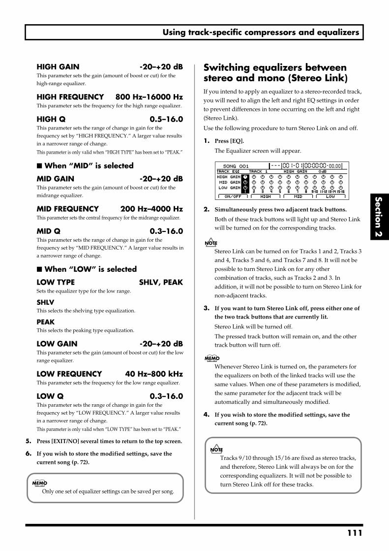
Using track-specific compressors and equalizers
Section 2
HIGH GAIN -20–+20 dBThis parameter sets the gain (amount of boost or cut) for the high-range equalizer.
HIGH FREQUENCY 800 Hz–16000 HzThis parameter sets the frequency for the high range equalizer.
HIGH Q 0.5–16.0This parameter sets the range of change in gain for the frequency set by “HIGH FREQUENCY.” A larger value results in a narrower range of change.
This parameter is only valid when “HIGH TYPE” has been set to “PEAK.”
When “MID” is selected
MID GAIN -20–+20 dBThis parameter sets the gain (amount of boost or cut) for the midrange equalizer.
MID FREQUENCY 200 Hz–4000 HzThis parameter sets the central frequency for the midrange equalizer.
MID Q 0.3–16.0This parameter sets the range of change in gain for the frequency set by “MID FREQUENCY.” A larger value results in a narrower range of change.
When “LOW” is selected
LOW TYPE SHLV, PEAKSets the equalizer type for the low range.
SHLVThis selects the shelving type equalization.
PEAKThis selects the peaking type equalization.
LOW GAIN -20–+20 dBThis parameter sets the gain (amount of boost or cut) for the low range equalizer.
LOW FREQUENCY 40 Hz–800 kHzThis parameter sets the frequency for the low range equalizer.
LOW Q 0.3–16.0This parameter sets the range of change in gain for the frequency set by “LOW FREQUENCY.” A larger value results in a narrower range of change.
This parameter is only valid when “LOW TYPE” has been set to “PEAK.”
5. Press [EXIT/NO] several times to return to the top screen.
6. If you wish to store the modified settings, save the current song (p. 72).
Switching equalizers between stereo and mono (Stereo Link)If you intend to apply an equalizer to a stereo-recorded track, you will need to align the left and right EQ settings in order to prevent differences in tone occurring on the left and right (Stereo Link).
Use the following procedure to turn Stereo Link on and off.
1. Press [EQ].
The Equalizer screen will appear.fig.32-03d
2. Simultaneously press two adjacent track buttons.
Both of these track buttons will light up and Stereo Link will be turned on for the corresponding tracks.
Stereo Link can be turned on for Tracks 1 and 2, Tracks 3 and 4, Tracks 5 and 6, and Tracks 7 and 8. It will not be possible to turn Stereo Link on for any other combination of tracks, such as Tracks 2 and 3. In addition, it will not be possible to turn on Stereo Link for non-adjacent tracks.
3. If you want to turn Stereo Link off, press either one of the two track buttons that are currently lit.
Stereo Link will be turned off.
The pressed track button will remain on, and the other track button will turn off.
Whenever Stereo Link is turned on, the parameters for the equalizers on both of the linked tracks will use the same values. When one of these parameters is modified, the same parameter for the adjacent track will be automatically and simultaneously modified.
4. If you wish to store the modified settings, save the current song (p. 72).
Only one set of equalizer settings can be saved per song.
Tracks 9/10 through 15/16 are fixed as stereo tracks, and therefore, Stereo Link will always be on for the corresponding equalizers. It will not be possible to turn Stereo Link off for these tracks.
111
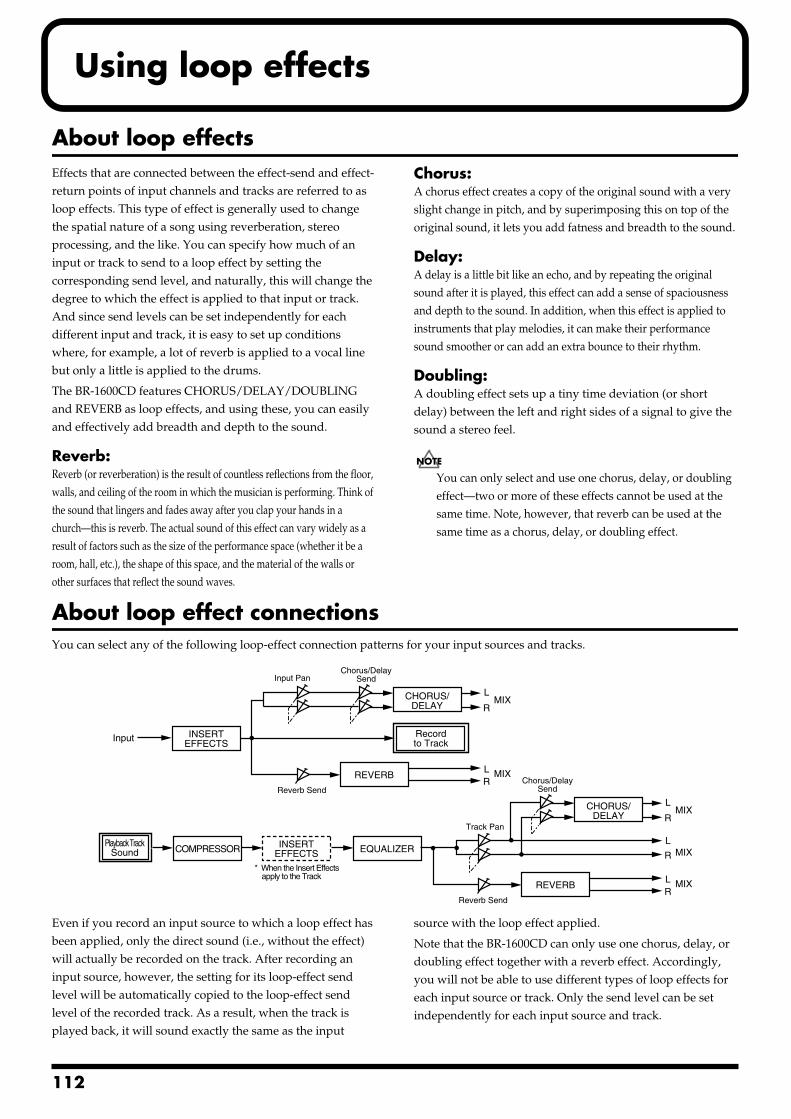
1
Using loop effects
About loop effectsEffects that are connected between the effect-send and effect-return points of input channels and tracks are referred to as loop effects. This type of effect is generally used to change the spatial nature of a song using reverberation, stereo processing, and the like. You can specify how much of an input or track to send to a loop effect by setting the corresponding send level, and naturally, this will change the degree to which the effect is applied to that input or track. And since send levels can be set independently for each different input and track, it is easy to set up conditions where, for example, a lot of reverb is applied to a vocal line but only a little is applied to the drums.
The BR-1600CD features CHORUS/DELAY/DOUBLING and REVERB as loop effects, and using these, you can easily and effectively add breadth and depth to the sound.
Reverb:Reverb (or reverberation) is the result of countless reflections from the floor, walls, and ceiling of the room in which the musician is performing. Think of the sound that lingers and fades away after you clap your hands in a church—this is reverb. The actual sound of this effect can vary widely as a result of factors such as the size of the performance space (whether it be a room, hall, etc.), the shape of this space, and the material of the walls or other surfaces that reflect the sound waves.
Chorus:A chorus effect creates a copy of the original sound with a very slight change in pitch, and by superimposing this on top of the original sound, it lets you add fatness and breadth to the sound.
Delay:A delay is a little bit like an echo, and by repeating the original sound after it is played, this effect can add a sense of spaciousness and depth to the sound. In addition, when this effect is applied to instruments that play melodies, it can make their performance sound smoother or can add an extra bounce to their rhythm.
Doubling:A doubling effect sets up a tiny time deviation (or short delay) between the left and right sides of a signal to give the sound a stereo feel.
You can only select and use one chorus, delay, or doubling effect—two or more of these effects cannot be used at the same time. Note, however, that reverb can be used at the same time as a chorus, delay, or doubling effect.
About loop effect connectionsYou can select any of the following loop-effect connection patterns for your input sources and tracks.fig.34-01
Even if you record an input source to which a loop effect has been applied, only the direct sound (i.e., without the effect) will actually be recorded on the track. After recording an input source, however, the setting for its loop-effect send level will be automatically copied to the loop-effect send level of the recorded track. As a result, when the track is played back, it will sound exactly the same as the input
source with the loop effect applied.
Note that the BR-1600CD can only use one chorus, delay, or doubling effect together with a reverb effect. Accordingly, you will not be able to use different types of loop effects for each input source or track. Only the send level can be set independently for each input source and track.
Input
REVERB
Recordto Track
Playback TrackSound
CHORUS/DELAY
LMIX
MIX
R
LR
Chorus/DelaySendInput Pan
Reverb Send
INSERTEFFECTS
REVERB
CHORUS/DELAY
EQUALIZERCOMPRESSOR
LMIX
MIX
MIX
R
L
R
LR
Chorus/DelaySend
Reverb Send
Track Pan
INSERTEFFECTS
* When the Insert Effects apply to the Track
12
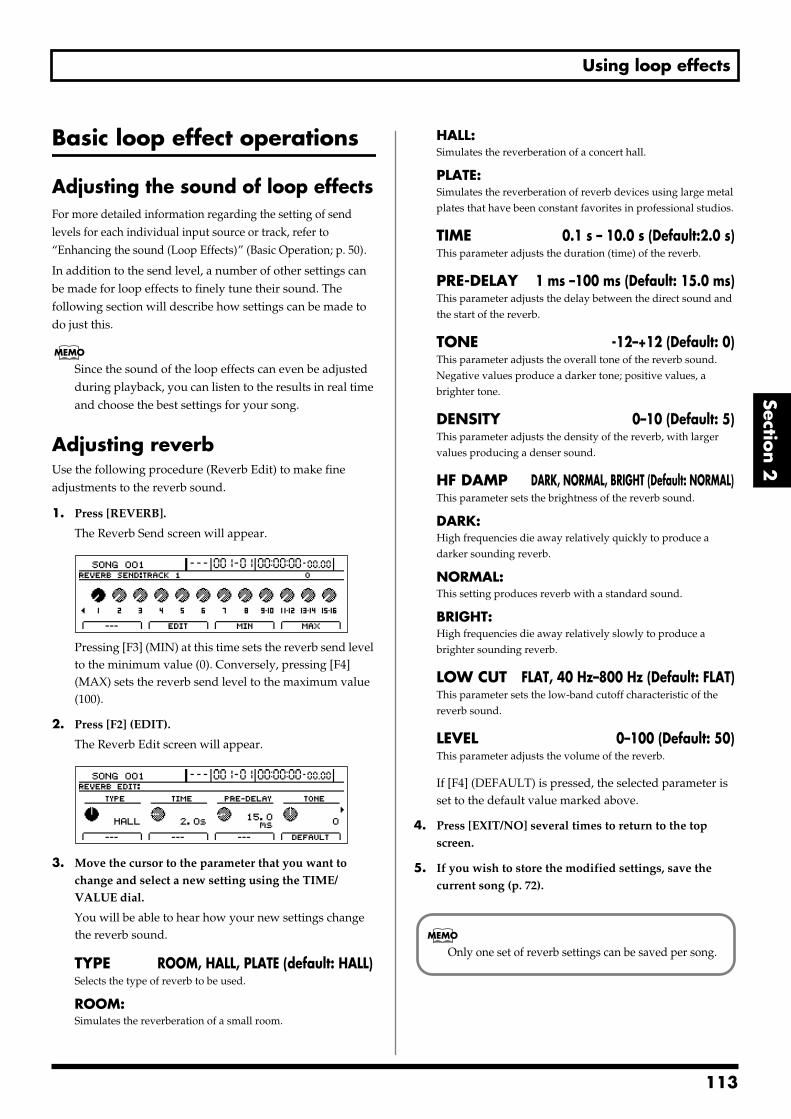
Using loop effects
Section 2
Basic loop effect operations
Adjusting the sound of loop effectsFor more detailed information regarding the setting of send levels for each individual input source or track, refer to “Enhancing the sound (Loop Effects)” (Basic Operation; p. 50).
In addition to the send level, a number of other settings can be made for loop effects to finely tune their sound. The following section will describe how settings can be made to do just this.
Since the sound of the loop effects can even be adjusted during playback, you can listen to the results in real time and choose the best settings for your song.
Adjusting reverbUse the following procedure (Reverb Edit) to make fine adjustments to the reverb sound.
1. Press [REVERB].
The Reverb Send screen will appear.fig.34-02d
Pressing [F3] (MIN) at this time sets the reverb send level to the minimum value (0). Conversely, pressing [F4] (MAX) sets the reverb send level to the maximum value (100).
2. Press [F2] (EDIT).
The Reverb Edit screen will appear.fig.34-02ad
3. Move the cursor to the parameter that you want to change and select a new setting using the TIME/VALUE dial.
You will be able to hear how your new settings change the reverb sound.
TYPE ROOM, HALL, PLATE (default: HALL)Selects the type of reverb to be used.
ROOM:Simulates the reverberation of a small room.
HALL:Simulates the reverberation of a concert hall.
PLATE:Simulates the reverberation of reverb devices using large metal plates that have been constant favorites in professional studios.
TIME 0.1 s – 10.0 s (Default:2.0 s)This parameter adjusts the duration (time) of the reverb.
PRE-DELAY 1 ms –100 ms (Default: 15.0 ms)This parameter adjusts the delay between the direct sound and the start of the reverb.
TONE -12–+12 (Default: 0)This parameter adjusts the overall tone of the reverb sound. Negative values produce a darker tone; positive values, a brighter tone.
DENSITY 0–10 (Default: 5)This parameter adjusts the density of the reverb, with larger values producing a denser sound.
HF DAMP DARK, NORMAL, BRIGHT (Default: NORMAL)This parameter sets the brightness of the reverb sound.
DARK:High frequencies die away relatively quickly to produce a darker sounding reverb.
NORMAL:This setting produces reverb with a standard sound.
BRIGHT:High frequencies die away relatively slowly to produce a brighter sounding reverb.
LOW CUT FLAT, 40 Hz–800 Hz (Default: FLAT)This parameter sets the low-band cutoff characteristic of the reverb sound.
LEVEL 0–100 (Default: 50)This parameter adjusts the volume of the reverb.
If [F4] (DEFAULT) is pressed, the selected parameter is set to the default value marked above.
4. Press [EXIT/NO] several times to return to the top screen.
5. If you wish to store the modified settings, save the current song (p. 72).
Only one set of reverb settings can be saved per song.
113
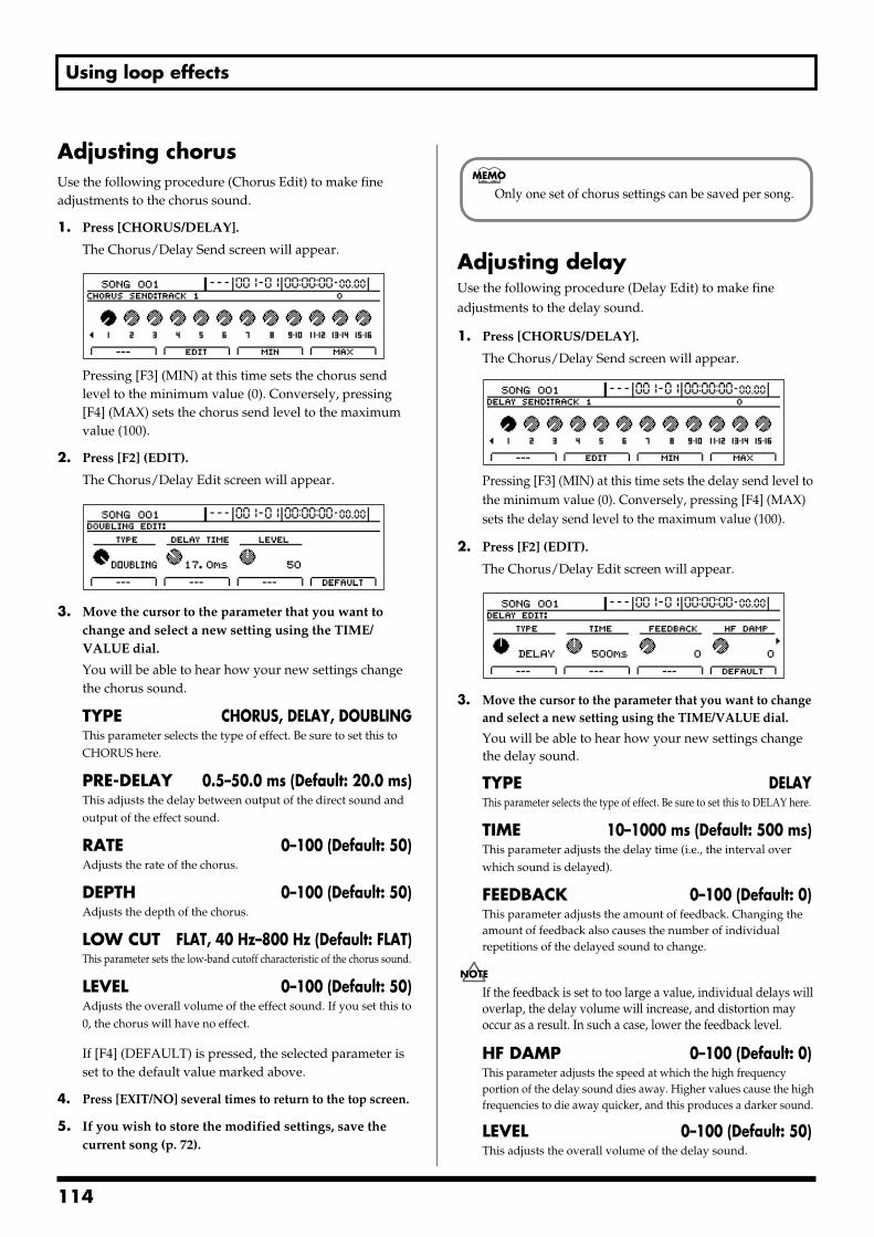
Using loop effects
Adjusting chorusUse the following procedure (Chorus Edit) to make fine adjustments to the chorus sound.
1. Press [CHORUS/DELAY].
The Chorus/Delay Send screen will appear.fig.34-03d
Pressing [F3] (MIN) at this time sets the chorus send level to the minimum value (0). Conversely, pressing [F4] (MAX) sets the chorus send level to the maximum value (100).
2. Press [F2] (EDIT).
The Chorus/Delay Edit screen will appear.fig.34-04d
3. Move the cursor to the parameter that you want to change and select a new setting using the TIME/VALUE dial.
You will be able to hear how your new settings change the chorus sound.
TYPE CHORUS, DELAY, DOUBLINGThis parameter selects the type of effect. Be sure to set this to CHORUS here.
PRE-DELAY 0.5–50.0 ms (Default: 20.0 ms)This adjusts the delay between output of the direct sound and output of the effect sound.
RATE 0–100 (Default: 50)Adjusts the rate of the chorus.
DEPTH 0–100 (Default: 50)Adjusts the depth of the chorus.
LOW CUT FLAT, 40 Hz–800 Hz (Default: FLAT)This parameter sets the low-band cutoff characteristic of the chorus sound.
LEVEL 0–100 (Default: 50)Adjusts the overall volume of the effect sound. If you set this to 0, the chorus will have no effect.
If [F4] (DEFAULT) is pressed, the selected parameter is set to the default value marked above.
4. Press [EXIT/NO] several times to return to the top screen.
5. If you wish to store the modified settings, save the current song (p. 72).
Adjusting delayUse the following procedure (Delay Edit) to make fine adjustments to the delay sound.
1. Press [CHORUS/DELAY].
The Chorus/Delay Send screen will appear.fig.34-03ad
Pressing [F3] (MIN) at this time sets the delay send level to the minimum value (0). Conversely, pressing [F4] (MAX) sets the delay send level to the maximum value (100).
2. Press [F2] (EDIT).
The Chorus/Delay Edit screen will appear.fig.34-04ad
3. Move the cursor to the parameter that you want to change and select a new setting using the TIME/VALUE dial.
You will be able to hear how your new settings change the delay sound.
TYPE DELAYThis parameter selects the type of effect. Be sure to set this to DELAY here.
TIME 10–1000 ms (Default: 500 ms)This parameter adjusts the delay time (i.e., the interval over which sound is delayed).
FEEDBACK 0–100 (Default: 0)This parameter adjusts the amount of feedback. Changing the amount of feedback also causes the number of individual repetitions of the delayed sound to change.
If the feedback is set to too large a value, individual delays will overlap, the delay volume will increase, and distortion may occur as a result. In such a case, lower the feedback level.
HF DAMP 0–100 (Default: 0)This parameter adjusts the speed at which the high frequency portion of the delay sound dies away. Higher values cause the high frequencies to die away quicker, and this produces a darker sound.
LEVEL 0–100 (Default: 50)This adjusts the overall volume of the delay sound.
Only one set of chorus settings can be saved per song.
114
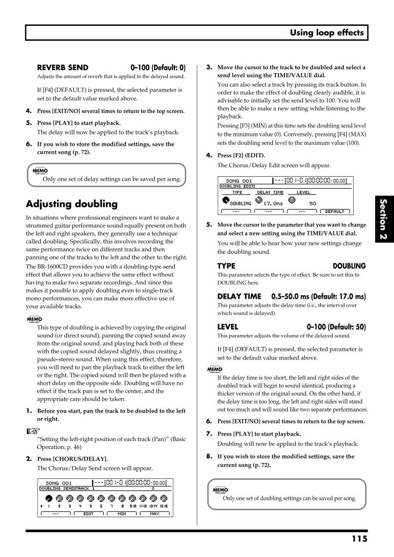
Using loop effects
Section 2
REVERB SEND 0–100 (Default: 0)Adjusts the amount of reverb that is applied to the delayed sound.
If [F4] (DEFAULT) is pressed, the selected parameter is set to the default value marked above.
4. Press [EXIT/NO] several times to return to the top screen.
5. Press [PLAY] to start playback.
The delay will now be applied to the track’s playback.
6. If you wish to store the modified settings, save the current song (p. 72).
Adjusting doublingIn situations where professional engineers want to make a strummed guitar performance sound equally present on both the left and right speakers, they generally use a technique called doubling. Specifically, this involves recording the same performance twice on different tracks and then panning one of the tracks to the left and the other to the right.
The BR-1600CD provides you with a doubling-type send effect that allows you to achieve the same effect without having to make two separate recordings. And since this makes it possible to apply doubling even to single-track mono performances, you can make more effective use of your available tracks.
This type of doubling is achieved by copying the original sound (or direct sound), panning the copied sound away from the original sound, and playing back both of these with the copied sound delayed slightly, thus creating a pseudo-stereo sound. When using this effect, therefore, you will need to pan the playback track to either the left or the right. The copied sound will then be played with a short delay on the opposite side. Doubling will have no effect if the track pan is set to the center, and the appropriate care should be taken.
1. Before you start, pan the track to be doubled to the left or right.
“Setting the left-right position of each track (Pan)” (Basic Operation; p. 46)
2. Press [CHORUS/DELAY].
The Chorus/Delay Send screen will appear.fig.34-103d
3. Move the cursor to the track to be doubled and select a send level using the TIME/VALUE dial.
You can also select a track by pressing its track button. In order to make the effect of doubling clearly audible, it is advisable to initially set the send level to 100. You will then be able to make a new setting while listening to the playback.
Pressing [F3] (MIN) at this time sets the doubling send level to the minimum value (0). Conversely, pressing [F4] (MAX) sets the doubling send level to the maximum value (100).
4. Press [F2] (EDIT).
The Chorus/Delay Edit screen will appear.fig.34-04d
5. Move the cursor to the parameter that you want to change and select a new setting using the TIME/VALUE dial.
You will be able to hear how your new settings change the doubling sound.
TYPE DOUBLINGThis parameter selects the type of effect. Be sure to set this to DOUBLING here.
DELAY TIME 0.5–50.0 ms (Default: 17.0 ms)This parameter adjusts the delay time (i.e., the interval over which sound is delayed).
LEVEL 0–100 (Default: 50)This parameter adjusts the volume of the delayed sound.
If [F4] (DEFAULT) is pressed, the selected parameter is set to the default value marked above.
If the delay time is too short, the left and right sides of the doubled track will begin to sound identical, producing a thicker version of the original sound. On the other hand, if the delay time is too long, the left and right sides will stand out too much and will sound like two separate performances.
6. Press [EXIT/NO] several times to return to the top screen.
7. Press [PLAY] to start playback.
Doubling will now be applied to the track’s playback.
8. If you wish to store the modified settings, save the current song (p. 72).
Only one set of delay settings can be saved per song.
Only one set of doubling settings can be saved per song.
115
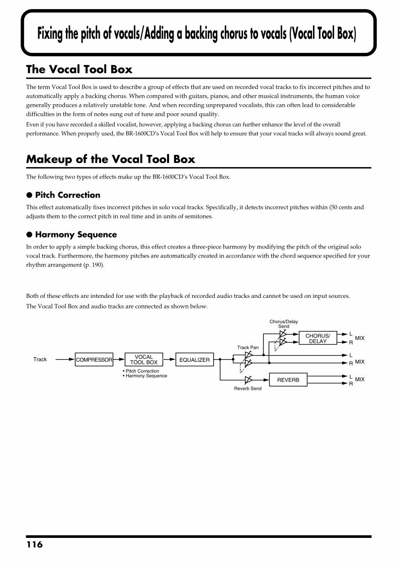
1
Fixing the pitch of vocals/Adding a backing chorus to vocals (Vocal Tool Box)
The Vocal Tool BoxThe term Vocal Tool Box is used to describe a group of effects that are used on recorded vocal tracks to fix incorrect pitches and to automatically apply a backing chorus. When compared with guitars, pianos, and other musical instruments, the human voice generally produces a relatively unstable tone. And when recording unprepared vocalists, this can often lead to considerable difficulties in the form of notes sung out of tune and poor sound quality.
Even if you have recorded a skilled vocalist, however, applying a backing chorus can further enhance the level of the overall performance. When properly used, the BR-1600CD’s Vocal Tool Box will help to ensure that your vocal tracks will always sound great.
Makeup of the Vocal Tool BoxThe following two types of effects make up the BR-1600CD’s Vocal Tool Box.
Pitch CorrectionThis effect automatically fixes incorrect pitches in solo vocal tracks. Specifically, it detects incorrect pitches within (50 cents and adjusts them to the correct pitch in real time and in units of semitones.
Harmony SequenceIn order to apply a simple backing chorus, this effect creates a three-piece harmony by modifying the pitch of the original solo vocal track. Furthermore, the harmony pitches are automatically created in accordance with the chord sequence specified for your rhythm arrangement (p. 190).
Both of these effects are intended for use with the playback of recorded audio tracks and cannot be used on input sources.
The Vocal Tool Box and audio tracks are connected as shown below.fig.35-01
Track
REVERB
CHORUS/DELAY
VOCALTOOL BOXCOMPRESSOR
LMIX
MIX
MIX
R
L
R
LR
Chorus/DelaySend
Reverb Send
• Pitch Correction• Harmony Sequence
Track Pan
EQUALIZER
16
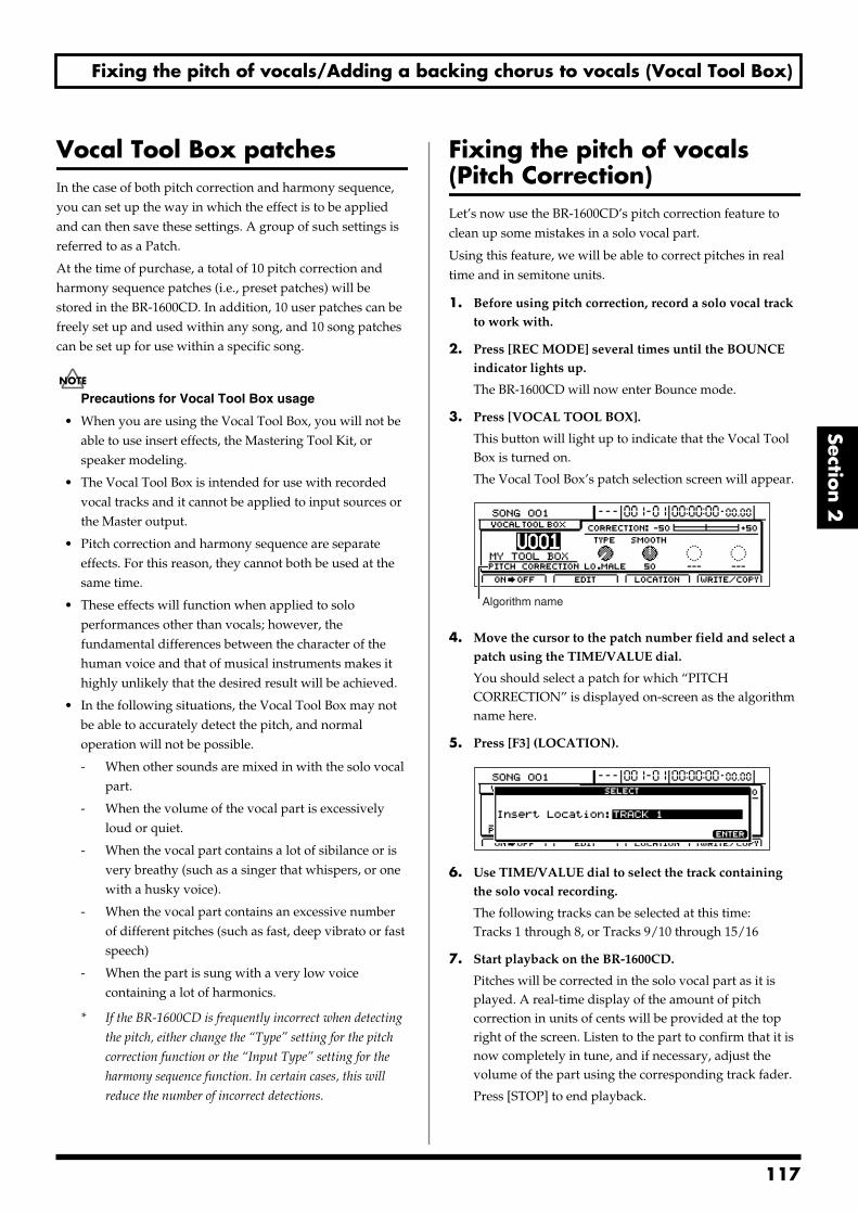
Fixing the pitch of vocals/Adding a backing chorus to vocals (Vocal Tool Box)
Section 2
Vocal Tool Box patchesIn the case of both pitch correction and harmony sequence, you can set up the way in which the effect is to be applied and can then save these settings. A group of such settings is referred to as a Patch.
At the time of purchase, a total of 10 pitch correction and harmony sequence patches (i.e., preset patches) will be stored in the BR-1600CD. In addition, 10 user patches can be freely set up and used within any song, and 10 song patches can be set up for use within a specific song.
Precautions for Vocal Tool Box usage
• When you are using the Vocal Tool Box, you will not be able to use insert effects, the Mastering Tool Kit, or speaker modeling.
• The Vocal Tool Box is intended for use with recorded vocal tracks and it cannot be applied to input sources or the Master output.
• Pitch correction and harmony sequence are separate effects. For this reason, they cannot both be used at the same time.
• These effects will function when applied to solo performances other than vocals; however, the fundamental differences between the character of the human voice and that of musical instruments makes it highly unlikely that the desired result will be achieved.
• In the following situations, the Vocal Tool Box may not be able to accurately detect the pitch, and normal operation will not be possible.
- When other sounds are mixed in with the solo vocal part.
- When the volume of the vocal part is excessively loud or quiet.
- When the vocal part contains a lot of sibilance or is very breathy (such as a singer that whispers, or one with a husky voice).
- When the vocal part contains an excessive number of different pitches (such as fast, deep vibrato or fast speech)
- When the part is sung with a very low voice containing a lot of harmonics.
* If the BR-1600CD is frequently incorrect when detecting
the pitch, either change the “Type” setting for the pitch
correction function or the “Input Type” setting for the
harmony sequence function. In certain cases, this will
reduce the number of incorrect detections.
Fixing the pitch of vocals (Pitch Correction) Let’s now use the BR-1600CD’s pitch correction feature to clean up some mistakes in a solo vocal part.
Using this feature, we will be able to correct pitches in real time and in semitone units.
1. Before using pitch correction, record a solo vocal track to work with.
2. Press [REC MODE] several times until the BOUNCE indicator lights up.
The BR-1600CD will now enter Bounce mode.
3. Press [VOCAL TOOL BOX].
This button will light up to indicate that the Vocal Tool Box is turned on.
The Vocal Tool Box’s patch selection screen will appear.fig.35-06d
4. Move the cursor to the patch number field and select a patch using the TIME/VALUE dial.
You should select a patch for which “PITCH CORRECTION” is displayed on-screen as the algorithm name here.
5. Press [F3] (LOCATION).fig.35-08d
6. Use TIME/VALUE dial to select the track containing the solo vocal recording.
The following tracks can be selected at this time:Tracks 1 through 8, or Tracks 9/10 through 15/16
7. Start playback on the BR-1600CD.
Pitches will be corrected in the solo vocal part as it is played. A real-time display of the amount of pitch correction in units of cents will be provided at the top right of the screen. Listen to the part to confirm that it is now completely in tune, and if necessary, adjust the volume of the part using the corresponding track fader.
Press [STOP] to end playback.
Algorithm name
117
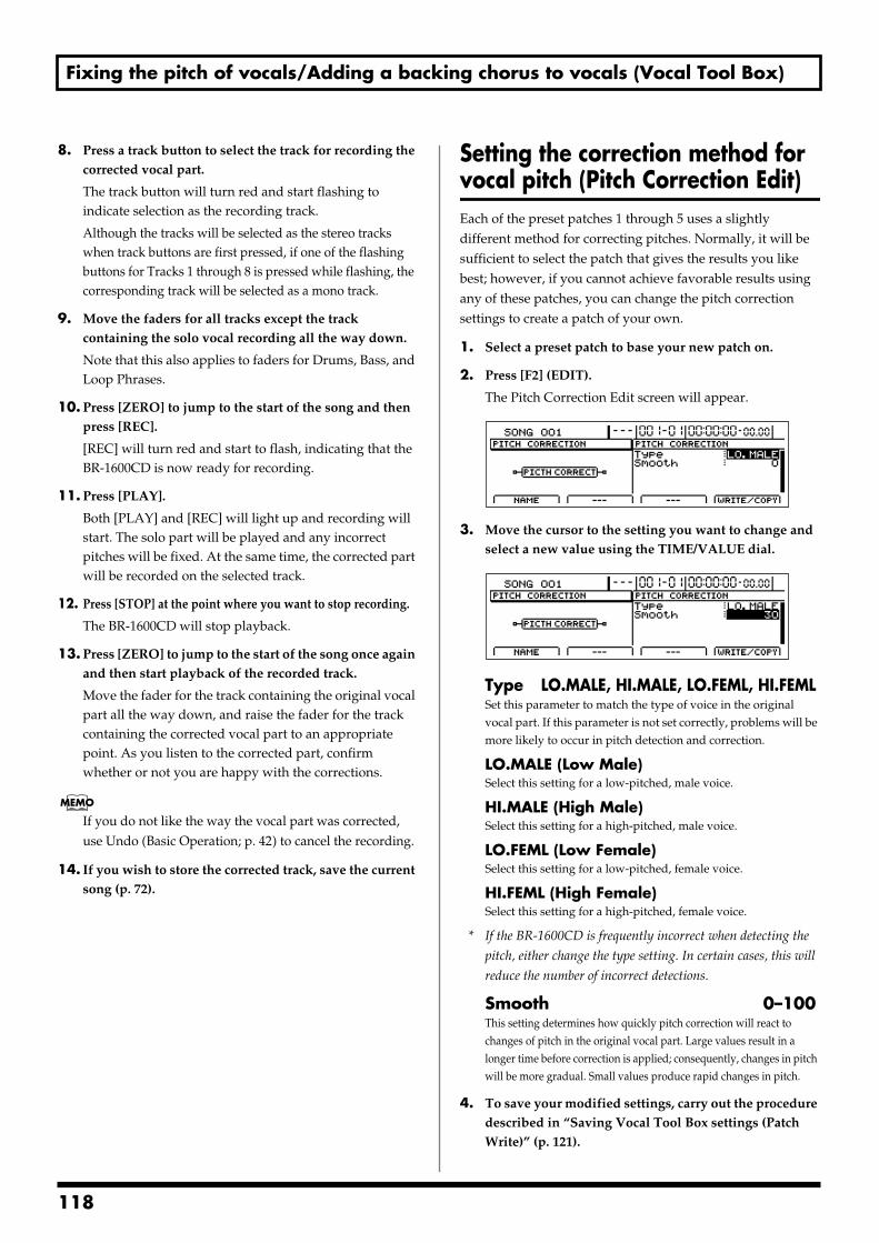
Fixing the pitch of vocals/Adding a backing chorus to vocals (Vocal Tool Box)
8. Press a track button to select the track for recording the corrected vocal part.
The track button will turn red and start flashing to indicate selection as the recording track.
Although the tracks will be selected as the stereo tracks when track buttons are first pressed, if one of the flashing buttons for Tracks 1 through 8 is pressed while flashing, the corresponding track will be selected as a mono track.
9. Move the faders for all tracks except the track containing the solo vocal recording all the way down.
Note that this also applies to faders for Drums, Bass, and Loop Phrases.
10. Press [ZERO] to jump to the start of the song and then press [REC].
[REC] will turn red and start to flash, indicating that the BR-1600CD is now ready for recording.
11. Press [PLAY].
Both [PLAY] and [REC] will light up and recording will start. The solo part will be played and any incorrect pitches will be fixed. At the same time, the corrected part will be recorded on the selected track.
12. Press [STOP] at the point where you want to stop recording.
The BR-1600CD will stop playback.
13. Press [ZERO] to jump to the start of the song once again and then start playback of the recorded track.
Move the fader for the track containing the original vocal part all the way down, and raise the fader for the track containing the corrected vocal part to an appropriate point. As you listen to the corrected part, confirm whether or not you are happy with the corrections.
If you do not like the way the vocal part was corrected, use Undo (Basic Operation; p. 42) to cancel the recording.
14. If you wish to store the corrected track, save the current song (p. 72).
Setting the correction method for vocal pitch (Pitch Correction Edit)Each of the preset patches 1 through 5 uses a slightly different method for correcting pitches. Normally, it will be sufficient to select the patch that gives the results you like best; however, if you cannot achieve favorable results using any of these patches, you can change the pitch correction settings to create a patch of your own.
1. Select a preset patch to base your new patch on.
2. Press [F2] (EDIT).
The Pitch Correction Edit screen will appear.fig.35-04d
3. Move the cursor to the setting you want to change and select a new value using the TIME/VALUE dial.
fig.35-05d
Type LO.MALE, HI.MALE, LO.FEML, HI.FEMLSet this parameter to match the type of voice in the original vocal part. If this parameter is not set correctly, problems will be more likely to occur in pitch detection and correction.
LO.MALE (Low Male)Select this setting for a low-pitched, male voice.
HI.MALE (High Male)Select this setting for a high-pitched, male voice.
LO.FEML (Low Female)Select this setting for a low-pitched, female voice.
HI.FEML (High Female)Select this setting for a high-pitched, female voice.
* If the BR-1600CD is frequently incorrect when detecting the
pitch, either change the type setting. In certain cases, this will
reduce the number of incorrect detections.
Smooth 0–100This setting determines how quickly pitch correction will react to changes of pitch in the original vocal part. Large values result in a longer time before correction is applied; consequently, changes in pitch will be more gradual. Small values produce rapid changes in pitch.
4. To save your modified settings, carry out the procedure described in “Saving Vocal Tool Box settings (Patch Write)” (p. 121).
118
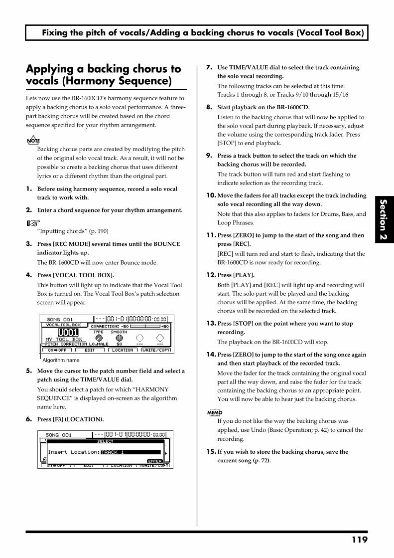
Fixing the pitch of vocals/Adding a backing chorus to vocals (Vocal Tool Box)
Section 2
Applying a backing chorus to vocals (Harmony Sequence) Lets now use the BR-1600CD’s harmony sequence feature to apply a backing chorus to a solo vocal performance. A three-part backing chorus will be created based on the chord sequence specified for your rhythm arrangement.
Backing chorus parts are created by modifying the pitch of the original solo vocal track. As a result, it will not be possible to create a backing chorus that uses different lyrics or a different rhythm than the original part.
1. Before using harmony sequence, record a solo vocal track to work with.
2. Enter a chord sequence for your rhythm arrangement.
“Inputting chords” (p. 190)
3. Press [REC MODE] several times until the BOUNCE indicator lights up.
The BR-1600CD will now enter Bounce mode.
4. Press [VOCAL TOOL BOX].
This button will light up to indicate that the Vocal Tool Box is turned on. The Vocal Tool Box’s patch selection screen will appear.
fig.35-06d
5. Move the cursor to the patch number field and select a patch using the TIME/VALUE dial.
You should select a patch for which “HARMONY SEQUENCE” is displayed on-screen as the algorithm name here.
6. Press [F3] (LOCATION).fig.35-108d
7. Use TIME/VALUE dial to select the track containing the solo vocal recording.
The following tracks can be selected at this time:Tracks 1 through 8, or Tracks 9/10 through 15/16
8. Start playback on the BR-1600CD.
Listen to the backing chorus that will now be applied to the solo vocal part during playback. If necessary, adjust the volume using the corresponding track fader. Press [STOP] to end playback.
9. Press a track button to select the track on which the backing chorus will be recorded.
The track button will turn red and start flashing to indicate selection as the recording track.
10. Move the faders for all tracks except the track including solo vocal recording all the way down.
Note that this also applies to faders for Drums, Bass, and Loop Phrases.
11. Press [ZERO] to jump to the start of the song and then press [REC].
[REC] will turn red and start to flash, indicating that the BR-1600CD is now ready for recording.
12. Press [PLAY].
Both [PLAY] and [REC] will light up and recording will start. The solo part will be played and the backing chorus will be applied. At the same time, the backing chorus will be recorded on the selected track.
13. Press [STOP] on the point where you want to stop recording.
The playback on the BR-1600CD will stop.
14. Press [ZERO] to jump to the start of the song once again and then start playback of the recorded track.
Move the fader for the track containing the original vocal part all the way down, and raise the fader for the track containing the backing chorus to an appropriate point. You will now be able to hear just the backing chorus.
If you do not like the way the backing chorus was applied, use Undo (Basic Operation; p. 42) to cancel the recording.
15. If you wish to store the backing chorus, save the current song (p. 72).
Algorithm name
119
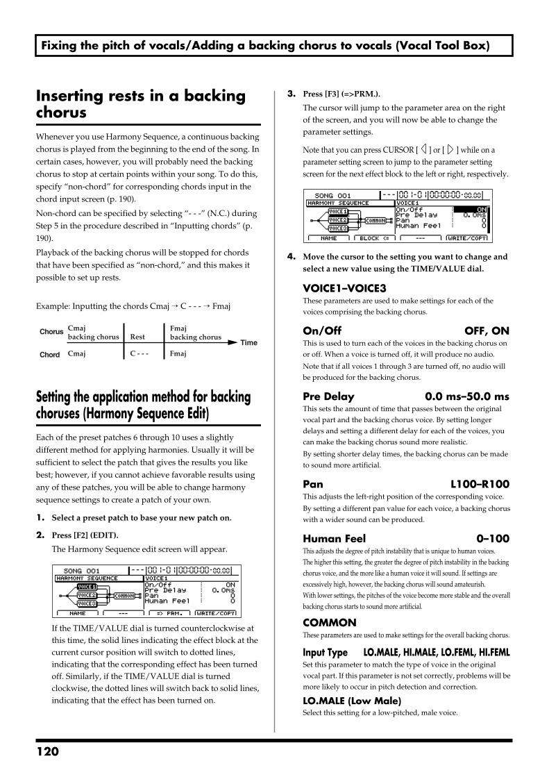
Fixing the pitch of vocals/Adding a backing chorus to vocals (Vocal Tool Box)
Inserting rests in a backing chorusWhenever you use Harmony Sequence, a continuous backing chorus is played from the beginning to the end of the song. In certain cases, however, you will probably need the backing chorus to stop at certain points within your song. To do this, specify “non-chord” for corresponding chords input in the chord input screen (p. 190).
Non-chord can be specified by selecting “- - -” (N.C.) during Step 5 in the procedure described in “Inputting chords” (p. 190).
Playback of the backing chorus will be stopped for chords that have been specified as “non-chord,” and this makes it possible to set up rests.
Example: Inputting the chords Cmaj → C - - - → Fmajfig.35-09a
Setting the application method for backing choruses (Harmony Sequence Edit) Each of the preset patches 6 through 10 uses a slightly different method for applying harmonies. Usually it will be sufficient to select the patch that gives the results you like best; however, if you cannot achieve favorable results using any of these patches, you will be able to change harmony sequence settings to create a patch of your own.
1. Select a preset patch to base your new patch on.
2. Press [F2] (EDIT).
The Harmony Sequence edit screen will appear.fig.35-09d
If the TIME/VALUE dial is turned counterclockwise at this time, the solid lines indicating the effect block at the current cursor position will switch to dotted lines, indicating that the corresponding effect has been turned off. Similarly, if the TIME/VALUE dial is turned clockwise, the dotted lines will switch back to solid lines, indicating that the effect has been turned on.
3. Press [F3] (=>PRM.).
The cursor will jump to the parameter area on the right of the screen, and you will now be able to change the parameter settings.
Note that you can press CURSOR [ ] or [ ] while on a parameter setting screen to jump to the parameter setting screen for the next effect block to the left or right, respectively.
fig.35-10d
4. Move the cursor to the setting you want to change and select a new value using the TIME/VALUE dial.
VOICE1–VOICE3These parameters are used to make settings for each of the voices comprising the backing chorus.
On/Off OFF, ONThis is used to turn each of the voices in the backing chorus on or off. When a voice is turned off, it will produce no audio.
Note that if all voices 1 through 3 are turned off, no audio will be produced for the backing chorus.
Pre Delay 0.0 ms–50.0 msThis sets the amount of time that passes between the original vocal part and the backing chorus voice. By setting longer delays and setting a different delay for each of the voices, you can make the backing chorus sound more realistic.
By setting shorter delay times, the backing chorus can be made to sound more artificial.
Pan L100–R100This adjusts the left-right position of the corresponding voice.
By setting a different pan value for each voice, a backing chorus with a wider sound can be produced.
Human Feel 0–100This adjusts the degree of pitch instability that is unique to human voices. The higher this setting, the greater the degree of pitch instability in the backing chorus voice, and the more like a human voice it will sound. If settings are excessively high, however, the backing chorus will sound amateurish.With lower settings, the pitches of the voice become more stable and the overall backing chorus starts to sound more artificial.
COMMONThese parameters are used to make settings for the overall backing chorus.
Input Type LO.MALE, HI.MALE, LO.FEML, HI.FEMLSet this parameter to match the type of voice in the original vocal part. If this parameter is not set correctly, problems will be more likely to occur in pitch detection and correction.
LO.MALE (Low Male)Select this setting for a low-pitched, male voice.
Chord
ChorusRest
Cmajbacking chorus
Cmaj FmajC - - -
Fmajbacking chorus
Time
120
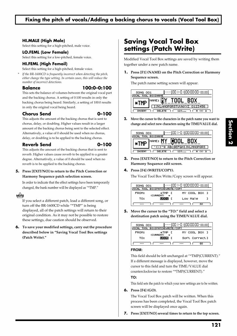
Fixing the pitch of vocals/Adding a backing chorus to vocals (Vocal Tool Box)
Section 2
HI.MALE (High Male)Select this setting for a high-pitched, male voice.
LO.FEML (Low Female)Select this setting for a low-pitched, female voice.
HI.FEML (High Femail)Select this setting for a high-pitched, female voice.
* If the BR-1600CD is frequently incorrect when detecting the pitch, either change the type setting. In certain cases, this will reduce the number of incorrect detections.
Balance 100:0–0:100This sets the balance of volumes between the original vocal part and the backing chorus. A setting of 0:100 results in only the backing chorus being heard. Similarly, a setting of 100:0 results in only the original vocal being heard.
Chorus Send 0–100This adjusts the amount of the backing chorus that is sent to chorus, delay, or doubling. Higher values result in a larger amount of the backing chorus being sent to the selected effect. Alternatively, a value of 0 should be used when no chorus, delay, or doubling is to be applied to the backing chorus.
Reverb Send 0–100This adjusts the amount of the backing chorus that is sent to reverb. Higher values cause reverb to be applied to a greater degree. Alternatively, a value of 0 should be used when no reverb is to be applied to the backing chorus.
5. Press [EXIT/NO] to return to the Pitch Correction or Harmony Sequence patch selection screen.
In order to indicate that the effect settings have been temporarily changed, the bank number will be displayed as “*TMP.”
If you select a different patch, load a different song, or turn off the BR-1600CD while “*TMP” is being displayed, all of the patch settings will return to their original condition. As it may not be possible to restore these settings, due caution should be observed.
6. To save your modified settings, carry out the procedure described below in “Saving Vocal Tool Box settings (Patch Write).”
Saving Vocal Tool Box settings (Patch Write) Modified Vocal Tool Box settings are saved by writing them together under a new patch name.
1. Press [F1] (NAME) on the Pitch Correction or Harmony Sequence screen.
The patch name setting screen will appear.fig.35-11d
2. Move the cursor to the characters in the patch name you want to change and select new characters using the TIME/VALUE dial.
fig.35-11ad
3. Press [EXIT/NO] to return to the Pitch Correction or Harmony Sequence edit screen.
4. Press [F4] (WRITE/COPY).
The Vocal Tool Box Write/Copy screen will appear.fig.35-12d
5. Move the cursor to the “TO:” field and select a destination patch using the TIME/VALUE dial.
fig.35-13d
FROM:
This field should be left unchanged at “*TMP(CURRENT).” If a different message is displayed, however, move the cursor to this field and turn the TIME/VALUE dial counterclockwise to restore “*TMP(CURRENT).”
TO:
This field sets the patch to which your new settings are to be written.
6. Press [F4] (GO).
The Vocal Tool Box patch will be written. When this process has been completed, the Vocal Tool Box patch screen will be displayed once again.
7. Press [EXIT/NO] several times to return to the top screen.
121
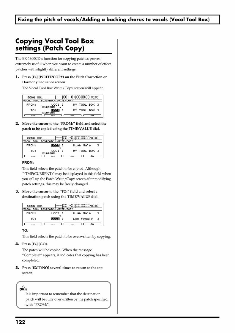
Fixing the pitch of vocals/Adding a backing chorus to vocals (Vocal Tool Box)
Copying Vocal Tool Box settings (Patch Copy) The BR-1600CD’s function for copying patches proves extremely useful when you want to create a number of effect patches with slightly different settings.
1. Press [F4] (WRITE/COPY) on the Pitch Correction or Harmony Sequence screen.
The Vocal Tool Box Write/Copy screen will appear.fig.35-14d
2. Move the cursor to the “FROM:” field and select the patch to be copied using the TIME/VALUE dial.
fig.35-14ad
FROM:
This field selects the patch to be copied. Although “*TMP(CURRENT)” may be displayed in this field when you call up the Patch Write/Copy screen after modifying patch settings, this may be freely changed.
3. Move the cursor to the “TO:” field and select a destination patch using the TIME/VALUE dial.
fig.35-14bd
TO:
This field selects the patch to be overwritten by copying.
4. Press [F4] (GO).
The patch will be copied. When the message “Complete!” appears, it indicates that copying has been completed.
5. Press [EXIT/NO] several times to return to the top screen.
It is important to remember that the destination patch will be fully overwritten by the patch specified with “FROM:”.
122
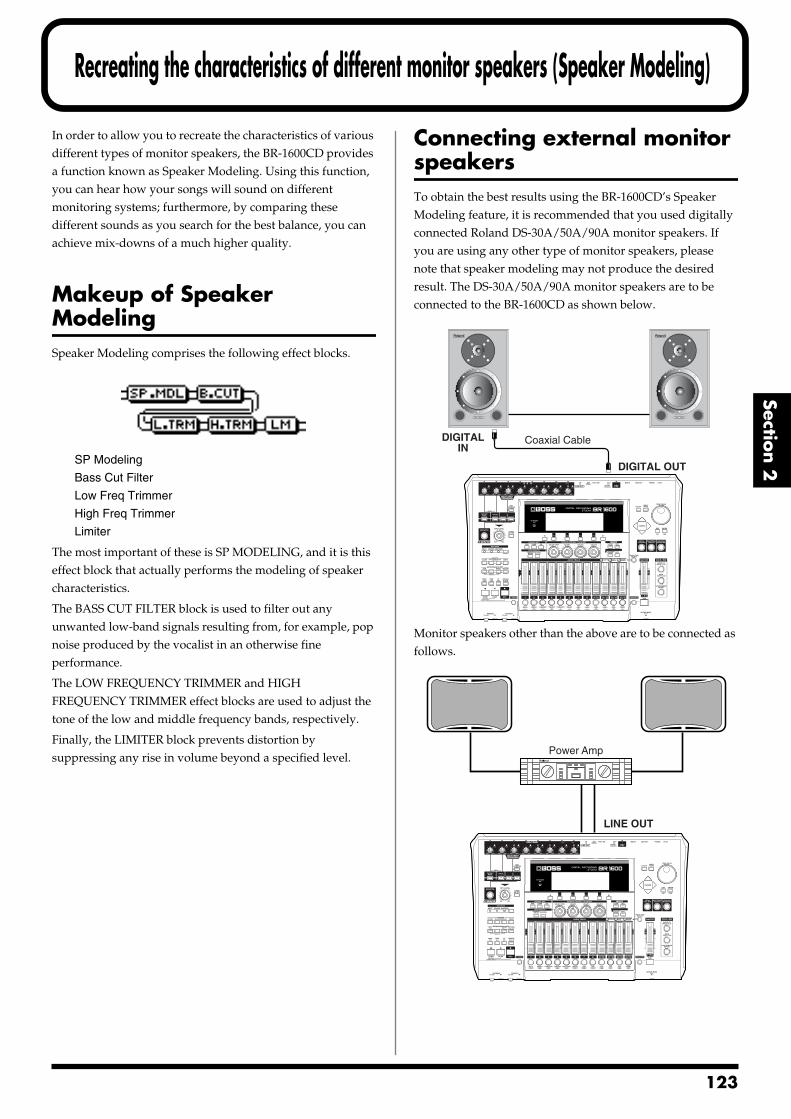
Recreating the characteristics of different monitor speakers (Speaker Modeling)
Section 2
In order to allow you to recreate the characteristics of various different types of monitor speakers, the BR-1600CD provides a function known as Speaker Modeling. Using this function, you can hear how your songs will sound on different monitoring systems; furthermore, by comparing these different sounds as you search for the best balance, you can achieve mix-downs of a much higher quality.
Makeup of Speaker ModelingSpeaker Modeling comprises the following effect blocks.fig.37-13d
SP Modeling
Bass Cut Filter
Low Freq Trimmer
High Freq Trimmer
Limiter
The most important of these is SP MODELING, and it is this effect block that actually performs the modeling of speaker characteristics.
The BASS CUT FILTER block is used to filter out any unwanted low-band signals resulting from, for example, pop noise produced by the vocalist in an otherwise fine performance.
The LOW FREQUENCY TRIMMER and HIGH FREQUENCY TRIMMER effect blocks are used to adjust the tone of the low and middle frequency bands, respectively.
Finally, the LIMITER block prevents distortion by suppressing any rise in volume beyond a specified level.
Connecting external monitor speakersTo obtain the best results using the BR-1600CD’s Speaker Modeling feature, it is recommended that you used digitally connected Roland DS-30A/50A/90A monitor speakers. If you are using any other type of monitor speakers, please note that speaker modeling may not produce the desired result. The DS-30A/50A/90A monitor speakers are to be connected to the BR-1600CD as shown below.fig.37-01
Monitor speakers other than the above are to be connected as follows.fig.37-02
DIGITAL OUT
DIGITALIN
Coaxial Cable
LINE OUT
Power Amp
123
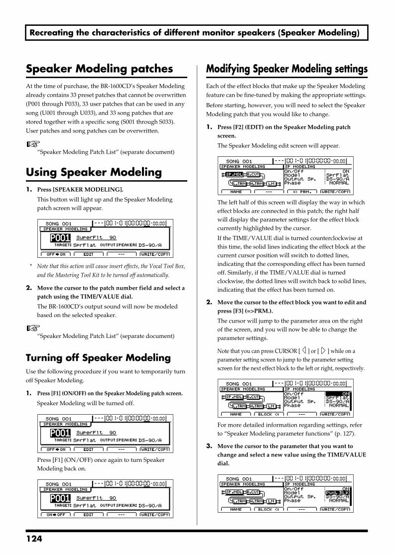
Recreating the characteristics of different monitor speakers (Speaker Modeling)
Speaker Modeling patchesAt the time of purchase, the BR-1600CD’s Speaker Modeling already contains 33 preset patches that cannot be overwritten (P001 through P033), 33 user patches that can be used in any song (U001 through U033), and 33 song patches that are stored together with a specific song (S001 through S033). User patches and song patches can be overwritten.
“Speaker Modeling Patch List” (separate document)
Using Speaker Modeling1. Press [SPEAKER MODELING].
This button will light up and the Speaker Modeling patch screen will appear.
fig.37-03d
* Note that this action will cause insert effects, the Vocal Tool Box,
and the Mastering Tool Kit to be turned off automatically.
2. Move the cursor to the patch number field and select a patch using the TIME/VALUE dial.
The BR-1600CD’s output sound will now be modeled based on the selected speaker.
“Speaker Modeling Patch List” (separate document)
Turning off Speaker ModelingUse the following procedure if you want to temporarily turn off Speaker Modeling.
1. Press [F1] (ON/OFF) on the Speaker Modeling patch screen.
Speaker Modeling will be turned off.fig.37-04d
Press [F1] (ON/OFF) once again to turn Speaker Modeling back on.
fig.37-05d
Modifying Speaker Modeling settingsEach of the effect blocks that make up the Speaker Modeling feature can be fine-tuned by making the appropriate settings.
Before starting, however, you will need to select the Speaker Modeling patch that you would like to change.
1. Press [F2] (EDIT) on the Speaker Modeling patch screen.
The Speaker Modeling edit screen will appear.fig.37-06d
The left half of this screen will display the way in which effect blocks are connected in this patch; the right half will display the parameter settings for the effect block currently highlighted by the cursor.
If the TIME/VALUE dial is turned counterclockwise at this time, the solid lines indicating the effect block at the current cursor position will switch to dotted lines, indicating that the corresponding effect has been turned off. Similarly, if the TIME/VALUE dial is turned clockwise, the dotted lines will switch back to solid lines, indicating that the effect has been turned on.
2. Move the cursor to the effect block you want to edit and press [F3] (=>PRM.).
The cursor will jump to the parameter area on the right of the screen, and you will now be able to change the parameter settings.
Note that you can press CURSOR [ ] or [ ] while on a parameter setting screen to jump to the parameter setting screen for the next effect block to the left or right, respectively.
fig.37-06ad
For more detailed information regarding settings, refer to “Speaker Modeling parameter functions” (p. 127).
3. Move the cursor to the parameter that you want to change and select a new value using the TIME/VALUE dial.
fig.37-07d
124
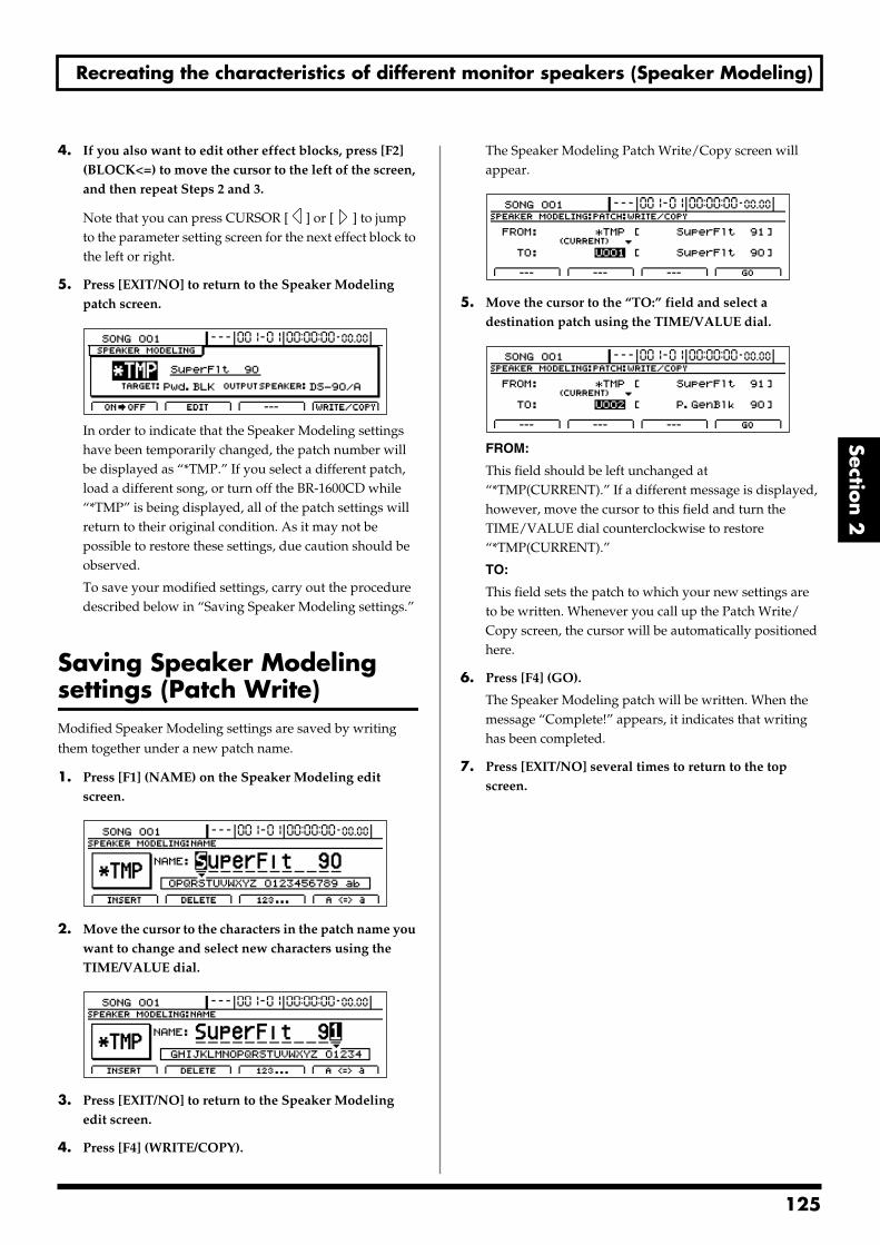
Recreating the characteristics of different monitor speakers (Speaker Modeling)
Section 2
4. If you also want to edit other effect blocks, press [F2] (BLOCK<=) to move the cursor to the left of the screen, and then repeat Steps 2 and 3.
Note that you can press CURSOR [ ] or [ ] to jump to the parameter setting screen for the next effect block to the left or right.
5. Press [EXIT/NO] to return to the Speaker Modeling patch screen.
fig.37-08d
In order to indicate that the Speaker Modeling settings have been temporarily changed, the patch number will be displayed as “*TMP.” If you select a different patch, load a different song, or turn off the BR-1600CD while “*TMP” is being displayed, all of the patch settings will return to their original condition. As it may not be possible to restore these settings, due caution should be observed.
To save your modified settings, carry out the procedure described below in “Saving Speaker Modeling settings.”
Saving Speaker Modeling settings (Patch Write)Modified Speaker Modeling settings are saved by writing them together under a new patch name.
1. Press [F1] (NAME) on the Speaker Modeling edit screen.
fig.37-09d
2. Move the cursor to the characters in the patch name you want to change and select new characters using the TIME/VALUE dial.
fig.37-09d
3. Press [EXIT/NO] to return to the Speaker Modeling edit screen.
4. Press [F4] (WRITE/COPY).
The Speaker Modeling Patch Write/Copy screen will appear.
fig.37-10d
5. Move the cursor to the “TO:” field and select a destination patch using the TIME/VALUE dial.
fig.37-11d
FROM:
This field should be left unchanged at “*TMP(CURRENT).” If a different message is displayed, however, move the cursor to this field and turn the TIME/VALUE dial counterclockwise to restore “*TMP(CURRENT).”
TO:
This field sets the patch to which your new settings are to be written. Whenever you call up the Patch Write/Copy screen, the cursor will be automatically positioned here.
6. Press [F4] (GO).
The Speaker Modeling patch will be written. When the message “Complete!” appears, it indicates that writing has been completed.
7. Press [EXIT/NO] several times to return to the top screen.
125
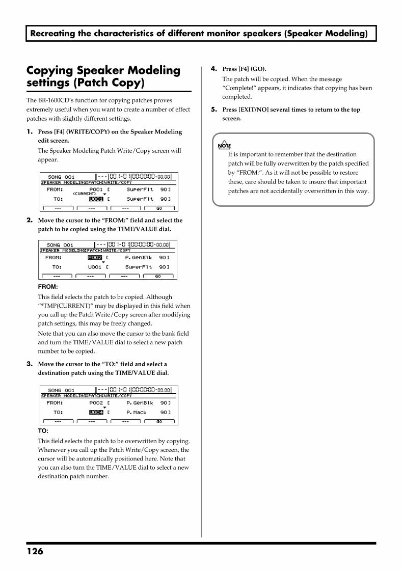
Recreating the characteristics of different monitor speakers (Speaker Modeling)
Copying Speaker Modeling settings (Patch Copy)The BR-1600CD’s function for copying patches proves extremely useful when you want to create a number of effect patches with slightly different settings.
1. Press [F4] (WRITE/COPY) on the Speaker Modeling edit screen.
The Speaker Modeling Patch Write/Copy screen will appear.
fig.37-12d
2. Move the cursor to the “FROM:” field and select the patch to be copied using the TIME/VALUE dial.
fig.37-12ad
FROM:
This field selects the patch to be copied. Although “*TMP(CURRENT)” may be displayed in this field when you call up the Patch Write/Copy screen after modifying patch settings, this may be freely changed.
Note that you can also move the cursor to the bank field and turn the TIME/VALUE dial to select a new patch number to be copied.
3. Move the cursor to the “TO:” field and select a destination patch using the TIME/VALUE dial.
fig.37-12bd
TO:
This field selects the patch to be overwritten by copying. Whenever you call up the Patch Write/Copy screen, the cursor will be automatically positioned here. Note that you can also turn the TIME/VALUE dial to select a new destination patch number.
4. Press [F4] (GO).
The patch will be copied. When the message “Complete!” appears, it indicates that copying has been completed.
5. Press [EXIT/NO] several times to return to the top screen.
It is important to remember that the destination patch will be fully overwritten by the patch specified by “FROM:”. As it will not be possible to restore these, care should be taken to insure that important patches are not accidentally overwritten in this way.
126
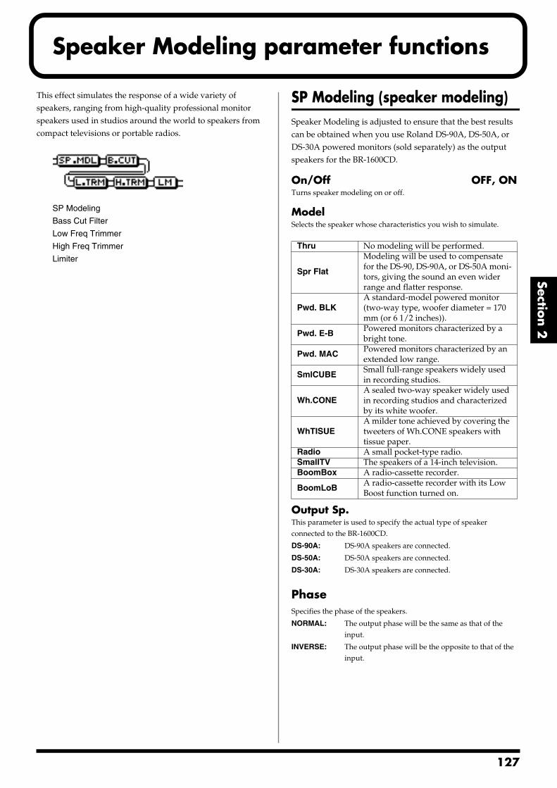
Speaker Modeling parameter functions
Section 2
This effect simulates the response of a wide variety of speakers, ranging from high-quality professional monitor speakers used in studios around the world to speakers from compact televisions or portable radios.fig.37-13d
SP Modeling
Bass Cut Filter
Low Freq Trimmer
High Freq Trimmer
Limiter
SP Modeling (speaker modeling)Speaker Modeling is adjusted to ensure that the best results can be obtained when you use Roland DS-90A, DS-50A, or DS-30A powered monitors (sold separately) as the output speakers for the BR-1600CD.
On/Off OFF, ONTurns speaker modeling on or off.
ModelSelects the speaker whose characteristics you wish to simulate.
Output Sp.This parameter is used to specify the actual type of speaker connected to the BR-1600CD.
DS-90A: DS-90A speakers are connected.
DS-50A: DS-50A speakers are connected.
DS-30A: DS-30A speakers are connected.
PhaseSpecifies the phase of the speakers.
NORMAL: The output phase will be the same as that of the input.
INVERSE: The output phase will be the opposite to that of the input.
Thru No modeling will be performed.
Spr Flat
Modeling will be used to compensate for the DS-90, DS-90A, or DS-50A moni-tors, giving the sound an even wider range and flatter response.
Pwd. BLKA standard-model powered monitor (two-way type, woofer diameter = 170 mm (or 6 1/2 inches)).
Pwd. E-BPowered monitors characterized by a bright tone.
Pwd. MACPowered monitors characterized by an extended low range.
SmlCUBESmall full-range speakers widely used in recording studios.
Wh.CONEA sealed two-way speaker widely used in recording studios and characterized by its white woofer.
WhTISUEA milder tone achieved by covering the tweeters of Wh.CONE speakers with tissue paper.
Radio A small pocket-type radio.SmallTV The speakers of a 14-inch television. BoomBox A radio-cassette recorder.
BoomLoBA radio-cassette recorder with its Low Boost function turned on.
127
Speaker Modeling parameter functions
Bass Cut FilterThis filter cuts out vocal pop and other unwanted low-band noise.
On/Off OFF, ONThis setting turns the Bass Cut Filter on or off.
Cut Off Freq THRU, 20 –2000 HzThis parameter sets the frequency below which vocal pop and other undesirable lower-range noises will be filtered out.
Low Freq TrimmerThis trimmer is used to process low frequencies.
On/Off OFF, ONSwitches the low frequency trimmer on or off.
Gain -12–+12 dBAdjusts the gain (i.e., the amount of boost or cut) for the low frequency trimmer.
Frequency 20–2000 HzSpecifies the center frequency for the low frequency trimmer.
High Freq TrimmerThis trimmer is used to process high frequencies.
On/Off OFF, ONSwitches the high frequency trimmer on or off.
Gain -12–+12 dBAdjusts the gain (i.e., the amount of boost or cut) for the high frequency trimmer.
Frequency 1.0–20.0 kHzSpecifies the center frequency for the high frequency trimmer.
LimiterA limiter reduces loud input levels to prevent distortion.
On/Off OFF, ONSwitches the limiter on or off.
Threshold -60–0 dBAdjust this parameter to match the input signal. Limiting will be applied to input levels in excess of this level.
Release 0–100This adjusts the time it takes for limiting to be removed once the signal level drops below the threshold.
Level -60–+24 dBThis parameter adjusts the overall volume.
128
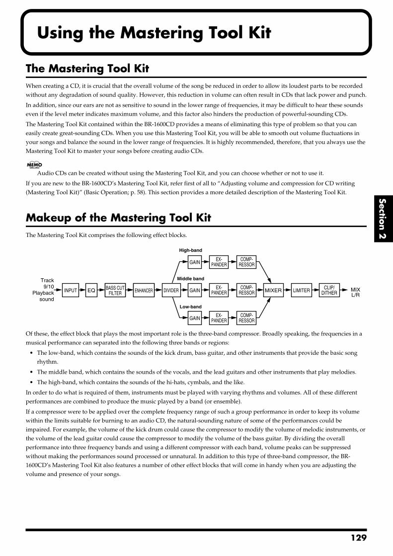
Using the Mastering Tool Kit
Section 2
The Mastering Tool KitWhen creating a CD, it is crucial that the overall volume of the song be reduced in order to allow its loudest parts to be recorded without any degradation of sound quality. However, this reduction in volume can often result in CDs that lack power and punch.
In addition, since our ears are not as sensitive to sound in the lower range of frequencies, it may be difficult to hear these sounds even if the level meter indicates maximum volume, and this factor also hinders the production of powerful-sounding CDs.
The Mastering Tool Kit contained within the BR-1600CD provides a means of eliminating this type of problem so that you can easily create great-sounding CDs. When you use this Mastering Tool Kit, you will be able to smooth out volume fluctuations in your songs and balance the sound in the lower range of frequencies. It is highly recommended, therefore, that you always use the Mastering Tool Kit to master your songs before creating audio CDs.
Audio CDs can be created without using the Mastering Tool Kit, and you can choose whether or not to use it.
If you are new to the BR-1600CD’s Mastering Tool Kit, refer first of all to “Adjusting volume and compression for CD writing (Mastering Tool Kit)” (Basic Operation; p. 58). This section provides a more detailed description of the Mastering Tool Kit.
Makeup of the Mastering Tool KitThe Mastering Tool Kit comprises the following effect blocks.fig.36-01
Of these, the effect block that plays the most important role is the three-band compressor. Broadly speaking, the frequencies in a musical performance can separated into the following three bands or regions:
• The low-band, which contains the sounds of the kick drum, bass guitar, and other instruments that provide the basic song rhythm.
• The middle band, which contains the sounds of the vocals, and the lead guitars and other instruments that play melodies.
• The high-band, which contains the sounds of the hi-hats, cymbals, and the like.
In order to do what is required of them, instruments must be played with varying rhythms and volumes. All of these different performances are combined to produce the music played by a band (or ensemble).
If a compressor were to be applied over the complete frequency range of such a group performance in order to keep its volume within the limits suitable for burning to an audio CD, the natural-sounding nature of some of the performances could be impaired. For example, the volume of the kick drum could cause the compressor to modify the volume of melodic instruments, or the volume of the lead guitar could cause the compressor to modify the volume of the bass guitar. By dividing the overall performance into three frequency bands and using a different compressor with each band, volume peaks can be suppressed without making the performances sound processed or unnatural. In addition to this type of three-band compressor, the BR-1600CD’s Mastering Tool Kit also features a number of other effect blocks that will come in handy when you are adjusting the volume and presence of your songs.
Track9/10
Playbacksound
INPUT BASS CUTFILTER
BASS CUTFILTER
BASS CUTFILTERENHANCEREQ GAIN MIXER LIMITER CLIP/
DITHEREX-
PANDERCOMP-
RESSOR
GAIN EX-PANDER
COMP-RESSOR
GAIN EX-PANDER
COMP-RESSOR
DIVIDER MIXL/R
High-band
Middle band
Low-band
129
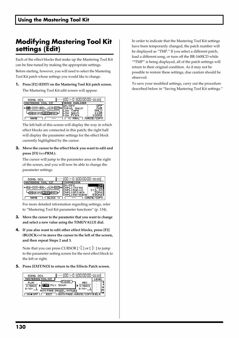
Using the Mastering Tool Kit
Modifying Mastering Tool Kit settings (Edit) Each of the effect blocks that make up the Mastering Tool Kit can be fine-tuned by making the appropriate settings.
Before starting, however, you will need to select the Mastering Tool Kit patch whose settings you would like to change.
1. Press [F2] (EDIT) on the Mastering Tool Kit patch screen.
The Mastering Tool Kit edit screen will appear.fig.36-02d
The left half of this screen will display the way in which effect blocks are connected in this patch; the right half will display the parameter settings for the effect block currently highlighted by the cursor.
2. Move the cursor to the effect block you want to edit and press [F3] (=>PRM.).
The cursor will jump to the parameter area on the right of the screen, and you will now be able to change the parameter settings.
fig.36-02ad
For more detailed information regarding settings, refer to “Mastering Tool Kit parameter functions” (p. 134).
3. Move the cursor to the parameter that you want to change and select a new value using the TIME/VALUE dial.
4. If you also want to edit other effect blocks, press [F2] (BLOCK<=) to move the cursor to the left of the screen, and then repeat Steps 2 and 3.
Note that you can press CURSOR [ ] or [ ] to jump to the parameter setting screen for the next effect block to the left or right.
5. Press [EXIT/NO] to return to the Effects Patch screen.fig.36-03d
In order to indicate that the Mastering Tool Kit settings have been temporarily changed, the patch number will be displayed as “TMP.” If you select a different patch, load a different song, or turn off the BR-1600CD while “*TMP” is being displayed, all of the patch settings will return to their original condition. As it may not be possible to restore these settings, due caution should be observed.
To save your modified settings, carry out the procedure described below in “Saving Mastering Tool Kit settings.”
130
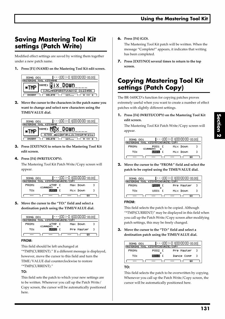
Using the Mastering Tool Kit
Section 2
Saving Mastering Tool Kit settings (Patch Write)Modified effect settings are saved by writing them together under a new patch name.
1. Press [F1] (NAME) on the Mastering Tool Kit edit screen. fig.36-04d
2. Move the cursor to the characters in the patch name you want to change and select new characters using the TIME/VALUE dial.
fig.36-04ad
3. Press [EXIT/NO] to return to the Mastering Tool Kit edit screen.
4. Press [F4] (WRITE/COPY).
The Mastering Tool Kit Patch Write/Copy screen will appear.
fig.36-05d
5. Move the cursor to the “TO:” field and select a destination patch using the TIME/VALUE dial.
fig.36-06d
FROM:
This field should be left unchanged at “*TMP(CURRENT).” If a different message is displayed, however, move the cursor to this field and turn the TIME/VALUE dial counterclockwise to restore “*TMP(CURRENT).”
TO:
This field sets the patch to which your new settings are to be written. Whenever you call up the Patch Write/Copy screen, the cursor will be automatically positioned here.
6. Press [F4] (GO).
The Mastering Tool Kit patch will be written. When the message “Complete!” appears, it indicates that writing has been completed.
7. Press [EXIT/NO] several times to return to the top screen.
Copying Mastering Tool Kit settings (Patch Copy) The BR-1600CD’s function for copying patches proves extremely useful when you want to create a number of effect patches with slightly different settings.
1. Press [F4] (WRITE/COPY) on the Mastering Tool Kit edit screen.
The Mastering Tool Kit Patch Write/Copy screen will appear.
fig.36-07d
2. Move the cursor to the “FROM:” field and select the patch to be copied using the TIME/VALUE dial.
fig.36-07ad
FROM:
This field selects the patch to be copied. Although “*TMP(CURRENT)” may be displayed in this field when you call up the Patch Write/Copy screen after modifying patch settings, this may be freely changed.
3. Move the cursor to the “TO:” field and select a destination patch using the TIME/VALUE dial.
fig.36-07bd
TO:
This field selects the patch to be overwritten by copying. Whenever you call up the Patch Write/Copy screen, the cursor will be automatically positioned here.
131
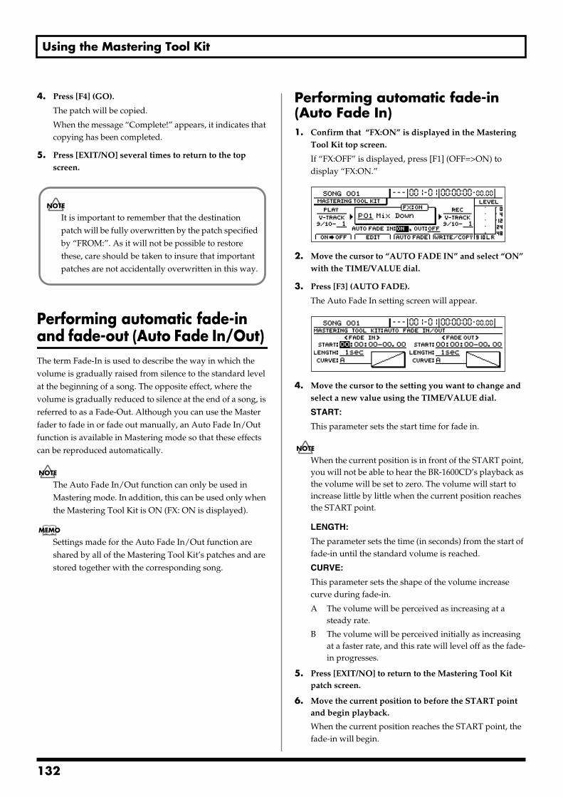
Using the Mastering Tool Kit
4. Press [F4] (GO).
The patch will be copied.
When the message “Complete!” appears, it indicates that copying has been completed.
5. Press [EXIT/NO] several times to return to the top screen.
Performing automatic fade-in and fade-out (Auto Fade In/Out) The term Fade-In is used to describe the way in which the volume is gradually raised from silence to the standard level at the beginning of a song. The opposite effect, where the volume is gradually reduced to silence at the end of a song, is referred to as a Fade-Out. Although you can use the Master fader to fade in or fade out manually, an Auto Fade In/Out function is available in Mastering mode so that these effects can be reproduced automatically.
The Auto Fade In/Out function can only be used in Mastering mode. In addition, this can be used only when the Mastering Tool Kit is ON (FX: ON is displayed).
Settings made for the Auto Fade In/Out function are shared by all of the Mastering Tool Kit’s patches and are stored together with the corresponding song.
Performing automatic fade-in (Auto Fade In)1. Confirm that “FX:ON” is displayed in the Mastering
Tool Kit top screen.
If “FX:OFF” is displayed, press [F1] (OFF=>ON) to display “FX:ON.”
fig.36-08d
2. Move the cursor to “AUTO FADE IN” and select “ON” with the TIME/VALUE dial.
3. Press [F3] (AUTO FADE).
The Auto Fade In setting screen will appear.fig.36-09d
4. Move the cursor to the setting you want to change and select a new value using the TIME/VALUE dial.
START:
This parameter sets the start time for fade in.
When the current position is in front of the START point, you will not be able to hear the BR-1600CD’s playback as the volume will be set to zero. The volume will start to increase little by little when the current position reaches the START point.
LENGTH:
The parameter sets the time (in seconds) from the start of fade-in until the standard volume is reached.
CURVE:
This parameter sets the shape of the volume increase curve during fade-in.
A The volume will be perceived as increasing at a steady rate.
B The volume will be perceived initially as increasing at a faster rate, and this rate will level off as the fade-in progresses.
5. Press [EXIT/NO] to return to the Mastering Tool Kit patch screen.
6. Move the current position to before the START point and begin playback.
When the current position reaches the START point, the fade-in will begin.
It is important to remember that the destination patch will be fully overwritten by the patch specified by “FROM:”. As it will not be possible to restore these, care should be taken to insure that important patches are not accidentally overwritten in this way.
132
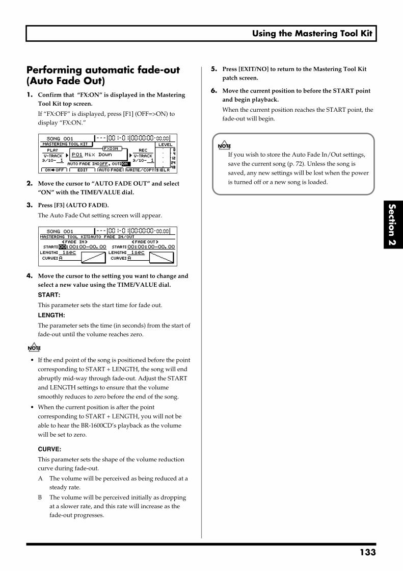
Using the Mastering Tool Kit
Section 2
Performing automatic fade-out (Auto Fade Out)1. Confirm that “FX:ON” is displayed in the Mastering
Tool Kit top screen.
If “FX:OFF” is displayed, press [F1] (OFF=>ON) to display “FX:ON.”
fig.36-10d
2. Move the cursor to “AUTO FADE OUT” and select “ON” with the TIME/VALUE dial.
3. Press [F3] (AUTO FADE).
The Auto Fade Out setting screen will appear.fig.36-11d
4. Move the cursor to the setting you want to change and select a new value using the TIME/VALUE dial.
START:
This parameter sets the start time for fade out.
LENGTH:
The parameter sets the time (in seconds) from the start of fade-out until the volume reaches zero.
• If the end point of the song is positioned before the point corresponding to START + LENGTH, the song will end abruptly mid-way through fade-out. Adjust the START and LENGTH settings to ensure that the volume smoothly reduces to zero before the end of the song.
• When the current position is after the point corresponding to START + LENGTH, you will not be able to hear the BR-1600CD’s playback as the volume will be set to zero.
CURVE:
This parameter sets the shape of the volume reduction curve during fade-out.
A The volume will be perceived as being reduced at a steady rate.
B The volume will be perceived initially as dropping at a slower rate, and this rate will increase as the fade-out progresses.
5. Press [EXIT/NO] to return to the Mastering Tool Kit patch screen.
6. Move the current position to before the START point and begin playback.
When the current position reaches the START point, the fade-out will begin.
If you wish to store the Auto Fade In/Out settings, save the current song (p. 72). Unless the song is saved, any new settings will be lost when the power is turned off or a new song is loaded.
133
1
Mastering Tool Kit parameter functions
This is a compressor effect that controls the volume level for each frequency range (lower range, midrange, and upper range) separately in order to even out the differences between them.
This allows you to achieve the optimal level when mixing down to MD or DAT, and when using CD-R disks to create your own original audio CDs.
Effect of the input “delay time”
With regular compressors, once excessive levels are detected, there is a momentary delay before the signal is suppressed. This algorithm circumvents this problem by using the input sound only for detection of the level, while a predetermined amount of delay is applied to the sound that is actually processed and output. The input delay time is the delay time setting used for this purpose.
Dividing the signal into separate frequency ranges
To divide the sound into separate frequency ranges, set the Low-Split Point (Split Freq L) and High-Split Point (Split Freq H).
Equalizer
Effect On/Off OFF, ONThis parameter turns the equalizer effect on or off.
Input Gain -24–+12 dBSets the overall volume before passing through the equalizer.
LowType SHLV, PEAKSets the lower-band equalizer type to shelving or peak.
Low Gain -12 –+12 dBSets the amount of boost or cut in the lower band.
Low Freq 20 Hz–2.0 kHzSets the center frequency for the lower band.
Low Q 0.3–16.0Sets the steepness of the frequency response curve at the lower band’s center frequency.
* The Low Q setting is disabled when “SHLV” is selected for the Low Type.
Low-Mid Gain -12–+12 dBSets the amount of boost or cut in the lower-middle band.
Low-Mid Freq 20 Hz–8.0 kHzSets the center frequency for the lower-middle band.
Low-Mid Q 0.3–16.0Sets the steepness of the frequency response curve at the lower-middle band’s center frequency.
Hi-Mid Gain -12–+12 dBSets the amount of boost or cut in the upper-middle band.
Hi-Mid Freq 20 Hz–8.0 kHzSets the center frequency for the upper-middle band.
Hi-Mid Q 0.3–16.0Sets the steepness of the frequency response curve at the upper-middle band’s center frequency.
High Type SHLV, PEAKSets the upper-band equalizer type to shelving or peak.
High Gain -12–+12 dBSets the amount of boost or cut in the upper band.
High Freq 1.4–20.0 kHzSets the center frequency for the upper band.
High Q 0.3–16.0Sets the frequency response curve steepness at the upper band’s center frequency.
* The High Q setting is disabled when “SHLV” is selected for the High Type.
Output Level -24–+12 dBSets the overall volume level after equalization.
34
Mastering Tool Kit parameter functions
Section 2
Bass Cut FilterThis filter cuts out vocal pop and other unwanted low-band noise.
Effect On/Off OFF, ONThis setting turns the Bass Cut Filter on or off.
Cut Off Freq 20 Hz–2.0 kHzThis parameter sets the frequency below which vocal pop and other undesirable lower-range noises will be filtered out.
EnhancerThis effect makes a sound livelier, and thus, more present in the mix.
Effect On/Off OFF, ONThis parameter turns the enhancer on or off.
Sensitivity 0–100Sets the degree to which the enhancer is to be applied.
Frequency 1.0–10.0 kHzSets the frequency at which the enhancer will begin to affect the sound.
Mix Level -24–+12 dBSets the volume of the effect sound.
InputThis effect divides the original sound into three frequency bands—namely, low, middle, and high.
Input Gain -24–+12 dBSets the overall volume level before the signal passes through the expander/compressor.
Delay Time 0–10 msThis parameter sets the amount of time by which the input sound is delayed.
Split Freq L 20–800 HzSets the low-band frequency at which the source sound is split into low and middle bands.
Split Freq H 1.6–16.0 kHzSets the upper-band frequency at which the source sound is split into middle and high bands.
ExpanderThis effect expands the dynamic range at a fixed ratio.
Effect On/Off OFF, ONThis setting turns the expander on or off.
ExpL: Thres -80–0 dBThis parameter sets the volume level at which the low-band expander begins to affect the sound.
ExpL: Ratio 1:1.00–1:16.0, 1:INFSets the ratio for output increase in the low band when the input level falls below the Lo threshold.
ExpL: Attack 0–100 msSets the time it takes for the low-band expander to start affecting the sound once the input level falls below the Lo threshold.
ExpL: Release 50–5000 msSets the time it takes for the low-band expander to stop affecting the sound once the input level rises above the Lo threshold.
ExpM: Thres -80–0 dBThis sets the volume level at which the midrange expander goes into effect.
ExpM: Ratio 1:1.00–1:16.0, 1:INFThis parameter sets the volume level at which the middle-band expander begins to affect the sound.
ExpM: Attack 0–100 msSets the time it takes for the middle-band expander to start affecting the sound once the input level falls below the Middle threshold.
ExpM: Release 50–5000 msSets the time it takes for the middle-band expander to stop affecting the sound once the input level rises above the Middle threshold.
ExpH: Thres -80–0 dBThis parameter sets the volume level at which the high-band expander begins to affect the sound.
ExpH: Ratio 1:1.00–1:16.0, 1:INFSets the ratio for output increase in the high band when the input level falls below the Hi threshold.
ExpH: Attack 0–100 msSets the time it takes for the high-band expander to start affecting the sound once the input level falls below the Hi threshold.
ExpH: Release 50–5000 msSets the time it takes for the high-band expander to stop affecting the sound once the input level rises above the Hi threshold.
135
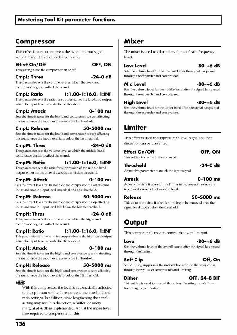
Mastering Tool Kit parameter functions
CompressorThis effect is used to compress the overall output signal when the input level exceeds a set value.
Effect On/Off OFF, ONThis setting turns the compressor on or off.
CmpL: Thres -24–0 dBThis parameter sets the volume level at which the low-band compressor begins to affect the sound.
CmpL: Ratio 1:1.00–1:16.0, 1:INFThis parameter sets the ratio for suppression of the low-band output when the input level exceeds the Lo threshold.
CmpL: Attack 0–100 msSets the time it takes for the low-band compressor to start affecting the sound once the input level exceeds the Lo threshold.
CmpL: Release 50–5000 msSets the time it takes for the low-band compressor to stop affecting the sound once the input level falls below the Lo threshold.
CmpM: Thres -24–0 dBThis parameter sets the volume level at which the middle-band compressor begins to affect the sound.
CmpM: Ratio 1:1.00–1:16.0, 1:INFThis parameter sets the ratio for suppression of the middle-band output when the input level exceeds the Middle threshold.
CmpM: Attack 0–100 msSets the time it takes for the middle-band compressor to start affecting the sound once the input level exceeds the Middle threshold.
CmpM: Release 50–5000 msSets the time it takes for the middle-band compressor to stop affecting the sound once the input level falls below the Middle threshold.
CmpH: Thres -24–0 dBThis parameter sets the volume level at which the high-band compressor begins to affect the sound.
CmpH: Ratio 1:1.00–1:16.0, 1:INFThis parameter sets the ratio for suppression of the high-band output when the input level exceeds the Hi threshold.
CmpH: Attack 0–100 msSets the time it takes for the high-band compressor to start affecting the sound once the input level exceeds the Hi threshold.
CmpH: Release 50–5000 msSets the time it takes for the high-band compressor to stop affecting the sound once the input level falls below the Hi threshold.
With this compressor, the level is automatically adjusted to the optimum setting in response to the threshold and ratio settings. In addition, since lengthening the attack setting may result in distortion, a buffer (or safety margin) of -6 dB is implemented. Adjust the mixer level if so required to compensate for this.
MixerThe mixer is used to adjust the volume of each frequency band.
Low Level -80–+6 dBSets the volume level for the low band after the signal has passed through the expander and compressor.
Mid Level -80–+6 dBSets the volume level for the middle band after the signal has passed through the expander and compressor.
High Level -80–+6 dBSets the volume level for the upper band after the signal has passed through the expander and compressor.
LimiterThis effect is used to suppress high-level signals so that distortion can be prevented.
Effect On/Off OFF, ONThis setting turns the limiter on or off.
Threshold -24–0 dBAdjust this parameter to match the input signal.
Attack 0–100 msAdjusts the time it takes for the limiter to become active once the input level exceeds the threshold level.
Release 50–5000 msThis adjusts the time it takes for limiting to be removed once the signal level drops below the threshold.
OutputThis component is used to control the overall output.
Level -80–+6 dBSets the volume level of the overall sound after the signal has passed through the limiter.
Soft Clip Off, OnSoft clipping suppresses the noticeable distortion that may occur through heavy use of compression and limiting.
Dither OFF, 24–8 BITThis setting is used to prevent the action of muting sounds from becoming too noticeable.
136
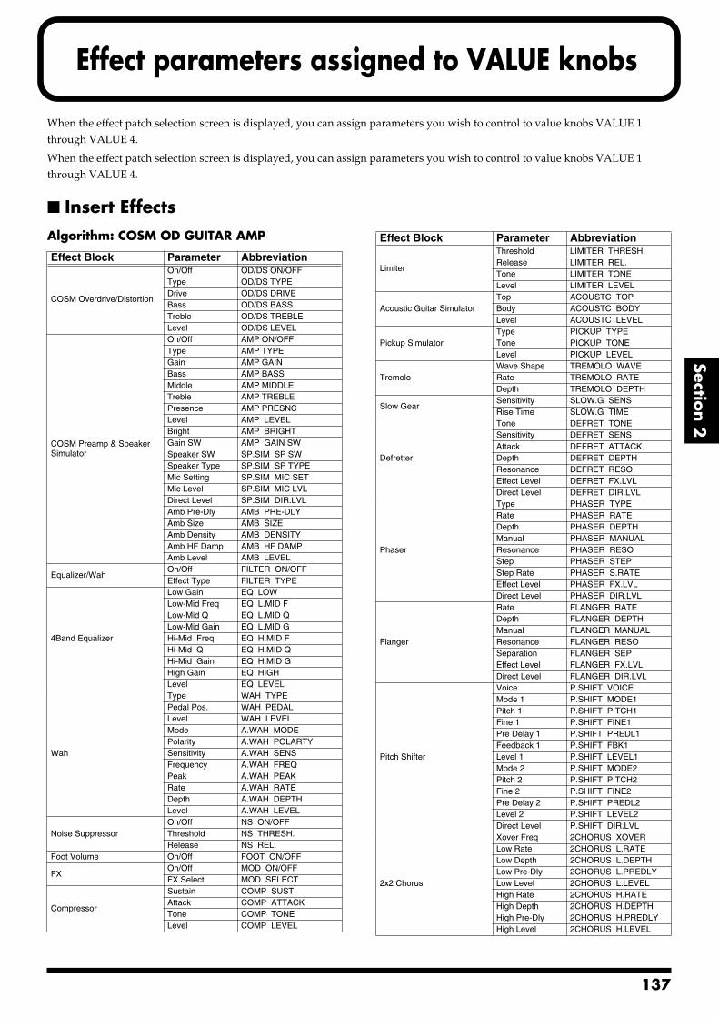
Effect parameters assigned to VALUE knobs
Section 2
When the effect patch selection screen is displayed, you can assign parameters you wish to control to value knobs VALUE 1 through VALUE 4.
When the effect patch selection screen is displayed, you can assign parameters you wish to control to value knobs VALUE 1 through VALUE 4.
Insert EffectsAlgorithm: COSM OD GUITAR AMP
Effect Block Parameter Abbreviation
COSM Overdrive/Distortion
On/Off OD/DS ON/OFFType OD/DS TYPEDrive OD/DS DRIVEBass OD/DS BASSTreble OD/DS TREBLELevel OD/DS LEVEL
COSM Preamp & Speaker Simulator
On/Off AMP ON/OFFType AMP TYPEGain AMP GAINBass AMP BASSMiddle AMP MIDDLETreble AMP TREBLEPresence AMP PRESNCLevel AMP LEVELBright AMP BRIGHTGain SW AMP GAIN SWSpeaker SW SP.SIM SP SWSpeaker Type SP.SIM SP TYPEMic Setting SP.SIM MIC SETMic Level SP.SIM MIC LVLDirect Level SP.SIM DIR.LVLAmb Pre-Dly AMB PRE-DLYAmb Size AMB SIZEAmb Density AMB DENSITYAmb HF Damp AMB HF DAMPAmb Level AMB LEVEL
Equalizer/WahOn/Off FILTER ON/OFFEffect Type FILTER TYPE
4Band Equalizer
Low Gain EQ LOWLow-Mid Freq EQ L.MID FLow-Mid Q EQ L.MID QLow-Mid Gain EQ L.MID GHi-Mid Freq EQ H.MID FHi-Mid Q EQ H.MID QHi-Mid Gain EQ H.MID GHigh Gain EQ HIGHLevel EQ LEVEL
Wah
Type WAH TYPEPedal Pos. WAH PEDALLevel WAH LEVELMode A.WAH MODEPolarity A.WAH POLARTYSensitivity A.WAH SENSFrequency A.WAH FREQPeak A.WAH PEAKRate A.WAH RATEDepth A.WAH DEPTHLevel A.WAH LEVEL
Noise SuppressorOn/Off NS ON/OFFThreshold NS THRESH.Release NS REL.
Foot Volume On/Off FOOT ON/OFF
FXOn/Off MOD ON/OFFFX Select MOD SELECT
Compressor
Sustain COMP SUSTAttack COMP ATTACKTone COMP TONELevel COMP LEVEL
Limiter
Threshold LIMITER THRESH.Release LIMITER REL.Tone LIMITER TONELevel LIMITER LEVEL
Acoustic Guitar SimulatorTop ACOUSTC TOPBody ACOUSTC BODYLevel ACOUSTC LEVEL
Pickup SimulatorType PICKUP TYPETone PICKUP TONELevel PICKUP LEVEL
TremoloWave Shape TREMOLO WAVERate TREMOLO RATEDepth TREMOLO DEPTH
Slow GearSensitivity SLOW.G SENSRise Time SLOW.G TIME
Defretter
Tone DEFRET TONESensitivity DEFRET SENSAttack DEFRET ATTACKDepth DEFRET DEPTHResonance DEFRET RESOEffect Level DEFRET FX.LVLDirect Level DEFRET DIR.LVL
Phaser
Type PHASER TYPERate PHASER RATEDepth PHASER DEPTHManual PHASER MANUALResonance PHASER RESOStep PHASER STEPStep Rate PHASER S.RATEEffect Level PHASER FX.LVLDirect Level PHASER DIR.LVL
Flanger
Rate FLANGER RATEDepth FLANGER DEPTHManual FLANGER MANUALResonance FLANGER RESOSeparation FLANGER SEPEffect Level FLANGER FX.LVLDirect Level FLANGER DIR.LVL
Pitch Shifter
Voice P.SHIFT VOICEMode 1 P.SHIFT MODE1Pitch 1 P.SHIFT PITCH1Fine 1 P.SHIFT FINE1Pre Delay 1 P.SHIFT PREDL1Feedback 1 P.SHIFT FBK1Level 1 P.SHIFT LEVEL1Mode 2 P.SHIFT MODE2Pitch 2 P.SHIFT PITCH2Fine 2 P.SHIFT FINE2Pre Delay 2 P.SHIFT PREDL2Level 2 P.SHIFT LEVEL2Direct Level P.SHIFT DIR.LVL
2x2 Chorus
Xover Freq 2CHORUS XOVERLow Rate 2CHORUS L.RATELow Depth 2CHORUS L.DEPTHLow Pre-Dly 2CHORUS L.PREDLYLow Level 2CHORUS L.LEVELHigh Rate 2CHORUS H.RATEHigh Depth 2CHORUS H.DEPTHHigh Pre-Dly 2CHORUS H.PREDLYHigh Level 2CHORUS H.LEVEL
Effect Block Parameter Abbreviation
137
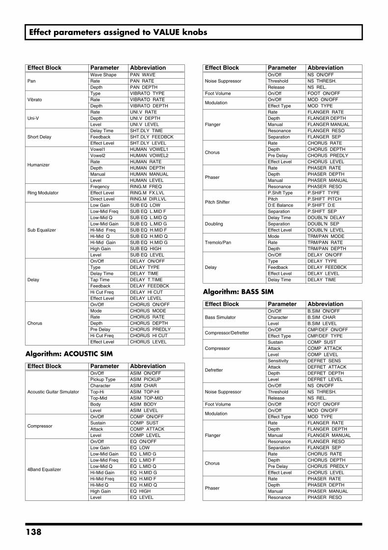
Effect parameters assigned to VALUE knobs
Algorithm: ACOUSTIC SIM
Algorithm: BASS SIM
PanWave Shape PAN WAVERate PAN RATEDepth PAN DEPTH
VibratoType VIBRATO TYPERate VIBRATO RATEDepth VIBRATO DEPTH
Uni-VRate UNI.V RATEDepth UNI.V DEPTHLevel UNI.V LEVEL
Short DelayDelay Time SHT.DLY TIMEFeedback SHT.DLY FEEDBCKEffect Level SHT.DLY LEVEL
Humanizer
Vowel1 HUMAN VOWEL1Vowel2 HUMAN VOWEL2Rate HUMAN RATEDepth HUMAN DEPTHManual HUMAN MANUALLevel HUMAN LEVEL
Ring ModulatorFreqency RING.M FREQEffect Level RING.M FX.LVLDirect Level RING.M DIR.LVL
Sub Equalizer
Low Gain SUB EQ LOWLow-Mid Freq SUB EQ L.MID FLow-Mid Q SUB EQ L.MID QLow-Mid Gain SUB EQ L.MID GHi-Mid Freq SUB EQ H.MID FHi-Mid Q SUB EQ H.MID QHi-Mid Gain SUB EQ H.MID GHigh Gain SUB EQ HIGHLevel SUB EQ LEVEL
Delay
On/Off DELAY ON/OFFType DELAY TYPEDelay Time DELAY TIMETap Time DELAY T.TIMEFeedback DELAY FEEDBCKHi Cut Freq DELAY HI CUTEffect Level DELAY LEVEL
Chorus
On/Off CHORUS ON/OFFMode CHORUS MODERate CHORUS RATEDepth CHORUS DEPTHPre Delay CHORUS PREDLYHi Cut Freq CHORUS HI CUTEffect Level CHORUS LEVEL
Effect Block Parameter Abbreviation
Acoustic Guitar Simulator
On/Off ASIM ON/OFFPickup Type ASIM PICKUPCharacter ASIM CHARTop-Hi ASIM TOP-HITop-Mid ASIM TOP-MIDBody ASIM BODYLevel ASIM LEVEL
Compressor
On/Off COMP ON/OFFSustain COMP SUSTAttack COMP ATTACKLevel COMP LEVEL
4Band Equalizer
On/Off EQ ON/OFFLow Gain EQ LOWLow-Mid Gain EQ L.MID GLow-Mid Freq EQ L.MID FLow-Mid Q EQ L.MID QHi-Mid Gain EQ H.MID GHi-Mid Freq EQ H.MID FHi-Mid Q EQ H.MID QHigh Gain EQ HIGHLevel EQ LEVEL
Effect Block Parameter Abbreviation
Noise SuppressorOn/Off NS ON/OFFThreshold NS THRESH.Release NS REL.
Foot Volume On/Off FOOT ON/OFF
ModulationOn/Off MOD ON/OFFEffect Type MOD TYPE
Flanger
Rate FLANGER RATEDepth FLANGER DEPTHManual FLANGER MANUALResonance FLANGER RESOSeparation FLANGER SEP
Chorus
Rate CHORUS RATEDepth CHORUS DEPTHPre Delay CHORUS PREDLYEffect Level CHORUS LEVEL
Phaser
Rate PHASER RATEDepth PHASER DEPTHManual PHASER MANUALResonance PHASER RESO
Pitch Shifter
P.Shift Type P.SHIFT TYPEPitch P.SHIFT PITCHD:E Balance P.SHIFT D:ESeparation P.SHIFT SEP
DoublingDelay Time DOUBL'N DELAYSeparation DOUBL'N SEP Effect Level DOUBL'N LEVEL
Tremolo/PanMode TRM/PAN MODERate TRM/PAN RATEDepth TRM/PAN DEPTH
Delay
On/Off DELAY ON/OFFType DELAY TYPEFeedback DELAY FEEDBCKEffect Level DELAY LEVELDelay Time DELAY TIME
Effect Block Parameter Abbreviation
Bass SimulatorOn/Off B.SIM ON/OFFCharacter B.SIM CHARLevel B.SIM LEVEL
Compressor/DefretterOn/Off CMP/DEF ON/OFFEffect Type CMP/DEF TYPE
CompressorSustain COMP SUSTAttack COMP ATTACKLevel COMP LEVEL
Defretter
Sensitivity DEFRET SENSAttack DEFRET ATTACKDepth DEFRET DEPTHLevel DEFRET LEVEL
Noise SuppressorOn/Off NS ON/OFFThreshold NS THRESH.Release NS REL.
Foot Volume On/Off FOOT ON/OFF
ModulationOn/Off MOD ON/OFFEffect Type MOD TYPE
Flanger
Rate FLANGER RATEDepth FLANGER DEPTHManual FLANGER MANUALResonance FLANGER RESOSeparation FLANGER SEP
Chorus
Rate CHORUS RATEDepth CHORUS DEPTHPre Delay CHORUS PREDLYEffect Level CHORUS LEVEL
Phaser
Rate PHASER RATEDepth PHASER DEPTHManual PHASER MANUALResonance PHASER RESO
Effect Block Parameter Abbreviation
138
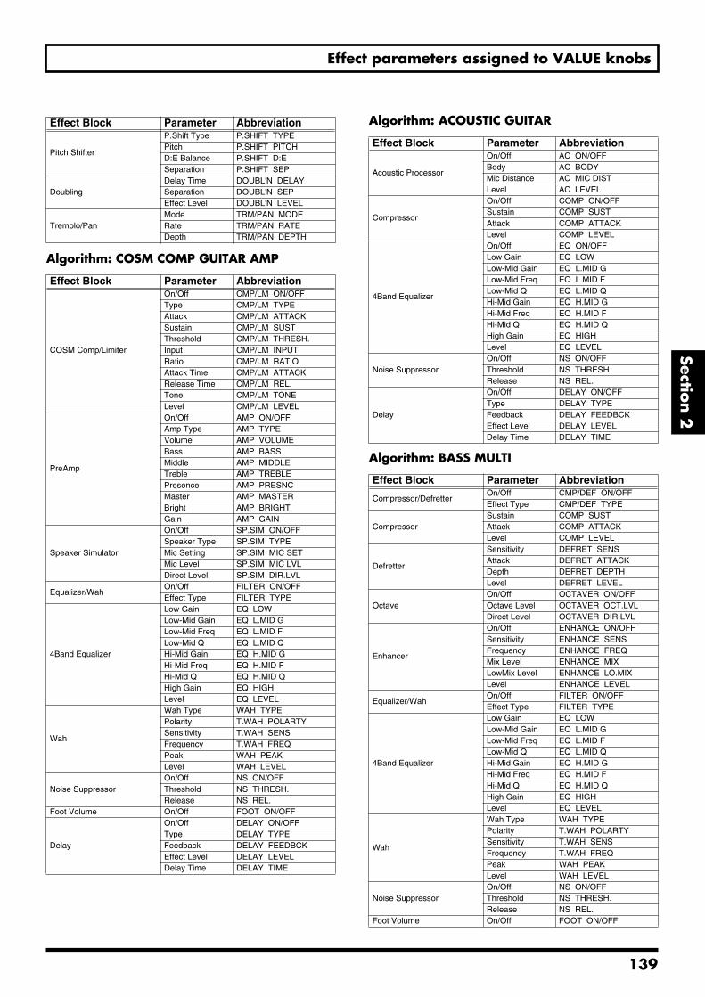
Effect parameters assigned to VALUE knobs
Section 2
Algorithm: COSM COMP GUITAR AMP
Algorithm: ACOUSTIC GUITAR
Algorithm: BASS MULTI
Pitch Shifter
P.Shift Type P.SHIFT TYPEPitch P.SHIFT PITCHD:E Balance P.SHIFT D:ESeparation P.SHIFT SEP
DoublingDelay Time DOUBL'N DELAYSeparation DOUBL'N SEPEffect Level DOUBL'N LEVEL
Tremolo/PanMode TRM/PAN MODERate TRM/PAN RATEDepth TRM/PAN DEPTH
Effect Block Parameter Abbreviation
COSM Comp/Limiter
On/Off CMP/LM ON/OFF Type CMP/LM TYPE Attack CMP/LM ATTACK Sustain CMP/LM SUST Threshold CMP/LM THRESH. Input CMP/LM INPUT Ratio CMP/LM RATIO Attack Time CMP/LM ATTACK Release Time CMP/LM REL.Tone CMP/LM TONELevel CMP/LM LEVEL
PreAmp
On/Off AMP ON/OFFAmp Type AMP TYPEVolume AMP VOLUMEBass AMP BASSMiddle AMP MIDDLETreble AMP TREBLEPresence AMP PRESNCMaster AMP MASTERBright AMP BRIGHTGain AMP GAIN
Speaker Simulator
On/Off SP.SIM ON/OFFSpeaker Type SP.SIM TYPEMic Setting SP.SIM MIC SETMic Level SP.SIM MIC LVLDirect Level SP.SIM DIR.LVL
Equalizer/WahOn/Off FILTER ON/OFFEffect Type FILTER TYPE
4Band Equalizer
Low Gain EQ LOWLow-Mid Gain EQ L.MID GLow-Mid Freq EQ L.MID FLow-Mid Q EQ L.MID QHi-Mid Gain EQ H.MID GHi-Mid Freq EQ H.MID FHi-Mid Q EQ H.MID QHigh Gain EQ HIGHLevel EQ LEVEL
Wah
Wah Type WAH TYPEPolarity T.WAH POLARTYSensitivity T.WAH SENSFrequency T.WAH FREQPeak WAH PEAKLevel WAH LEVEL
Noise SuppressorOn/Off NS ON/OFFThreshold NS THRESH.Release NS REL.
Foot Volume On/Off FOOT ON/OFF
Delay
On/Off DELAY ON/OFFType DELAY TYPEFeedback DELAY FEEDBCKEffect Level DELAY LEVELDelay Time DELAY TIME
Effect Block Parameter Abbreviation
Effect Block Parameter Abbreviation
Acoustic Processor
On/Off AC ON/OFFBody AC BODYMic Distance AC MIC DISTLevel AC LEVEL
Compressor
On/Off COMP ON/OFFSustain COMP SUSTAttack COMP ATTACKLevel COMP LEVEL
4Band Equalizer
On/Off EQ ON/OFFLow Gain EQ LOWLow-Mid Gain EQ L.MID GLow-Mid Freq EQ L.MID FLow-Mid Q EQ L.MID QHi-Mid Gain EQ H.MID GHi-Mid Freq EQ H.MID FHi-Mid Q EQ H.MID QHigh Gain EQ HIGHLevel EQ LEVEL
Noise SuppressorOn/Off NS ON/OFFThreshold NS THRESH.Release NS REL.
Delay
On/Off DELAY ON/OFFType DELAY TYPEFeedback DELAY FEEDBCKEffect Level DELAY LEVELDelay Time DELAY TIME
Effect Block Parameter Abbreviation
Compressor/DefretterOn/Off CMP/DEF ON/OFFEffect Type CMP/DEF TYPE
CompressorSustain COMP SUSTAttack COMP ATTACK Level COMP LEVEL
Defretter
Sensitivity DEFRET SENSAttack DEFRET ATTACKDepth DEFRET DEPTHLevel DEFRET LEVEL
OctaveOn/Off OCTAVER ON/OFFOctave Level OCTAVER OCT.LVLDirect Level OCTAVER DIR.LVL
Enhancer
On/Off ENHANCE ON/OFFSensitivity ENHANCE SENSFrequency ENHANCE FREQMix Level ENHANCE MIXLowMix Level ENHANCE LO.MIXLevel ENHANCE LEVEL
Equalizer/WahOn/Off FILTER ON/OFFEffect Type FILTER TYPE
4Band Equalizer
Low Gain EQ LOWLow-Mid Gain EQ L.MID GLow-Mid Freq EQ L.MID FLow-Mid Q EQ L.MID QHi-Mid Gain EQ H.MID GHi-Mid Freq EQ H.MID FHi-Mid Q EQ H.MID QHigh Gain EQ HIGHLevel EQ LEVEL
Wah
Wah Type WAH TYPEPolarity T.WAH POLARTYSensitivity T.WAH SENSFrequency T.WAH FREQPeak WAH PEAKLevel WAH LEVEL
Noise SuppressorOn/Off NS ON/OFFThreshold NS THRESH.Release NS REL.
Foot Volume On/Off FOOT ON/OFF
139
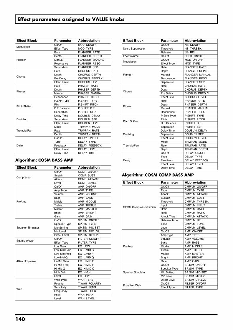
Effect parameters assigned to VALUE knobs
Algorithm: COSM BASS AMP
Algorithm: COSM COMP BASS AMP
ModulationOn/Off MOD ON/OFFEffect Type MOD TYPE
Flanger
Rate FLANGER RATEDepth FLANGER DEPTHManual FLANGER MANUALResonance FLANGER RESOSeparation FLANGER SEP
Chorus
Rate CHORUS RATEDepth CHORUS DEPTHPre Delay CHORUS PREDLYEffect Level CHORUS LEVEL
Phaser
Rate PHASER RATEDepth PHASER DEPTHManual PHASER MANUALResonance PHASER RESO
Pitch Shifter
P.Shift Type P.SHIFT TYPEPitch P.SHIFT PITCHD:E Balance P.SHIFT D:ESeparation P.SHIFT SEP
DoublingDelay Time DOUBL'N DELAYSeparation DOUBL'N SEPEffect Level DOUBL'N LEVEL
Tremolo/PanMode TRM/PAN MODERate TRM/PAN RATEDepth TRM/PAN DEPTH
Delay
On/Off DELAY ON/OFFType DELAY TYPEFeedback DELAY FEEDBCKEffect Level DELAY LEVELDelay Time DELAY TIME
Effect Block Parameter Abbreviation
Compressor
On/Off COMP ON/OFFSustain COMP SUSTAttack COMP ATTACKLevel COMP LEVEL
PreAmp
On/Off AMP ON/OFFAmp Type AMP TYPEVolume AMP VOLUMEBass AMP BASSMiddle AMP MIDDLETreble AMP TREBLEMaster AMP MASTERBright AMP BRIGHTGain AMP GAIN
Speaker Simulator
On/Off SP.SIM ON/OFFSpeaker Type SP.SIM TYPEMic Setting SP.SIM MIC SETMic Level SP.SIM MIC LVLDirect Level SP.SIM DIR.LVL
Equalizer/WahOn/Off FILTER ON/OFFEffect Type FILTER TYPE
4Band Equalizer
Low Gain EQ LOWLow-Mid Gain EQ L.MID GLow-Mid Freq EQ L.MID FLow-Mid Q EQ L.MID QHi-Mid Gain EQ H.MID GHi-Mid Freq EQ H.MID FHi-Mid Q EQ H.MID QHigh Gain EQ HIGHLevel EQ LEVEL
Wah
Wah Type WAH TYPEPolarity T.WAH POLARTYSensitivity T.WAH SENSFrequency T.WAH FREQPeak WAH PEAKLevel WAH LEVEL
Effect Block Parameter Abbreviation
Noise SuppressorOn/Off NS ON/OFFThreshold NS THRESH.Release NS REL.
Foot Volume On/Off FOOT ON/OFF
ModulationOn/Off MOD ON/OFFEffect Type MOD TYPE
Flanger
Rate FLANGER RATEDepth FLANGER DEPTHManual FLANGER MANUALResonance FLANGER RESOSeparation FLANGER SEP
Chorus
Rate CHORUS RATEDepth CHORUS DEPTHPre Delay CHORUS PREDLYEffect Level CHORUS LEVEL
Phaser
Rate PHASER RATEDepth PHASER DEPTHManual PHASER MANUALResonance PHASER RESO
Pitch Shifter
P.Shift Type P.SHIFT TYPEPitch P.SHIFT PITCHD:E Balance P.SHIFT D:ESeparation P.SHIFT SEP
DoublingDelay Time DOUBL'N DELAYSeparation DOUBL'N SEPEffect Level DOUBL'N LEVEL
Tremolo/PanMode TRM/PAN MODERate TRM/PAN RATEDepth TRM/PAN DEPTH
Delay
On/Off DELAY ON/OFFType DELAY TYPEFeedback DELAY FEEDBCKEffect Level DELAY LEVELDelay Time DELAY TIME
Effect Block Parameter Abbreviation
COSM Compressor/Limiter
On/Off CMP/LM ON/OFFType CMP/LM TYPEAttack CMP/LM ATTACKSustain CMP/LM SUSTThreshold CMP/LM THRESH.Input CMP/LM INPUTRatio CMP/LM RATIORatio CMP/LM RATIOAttack Time CMP/LM ATTACKRelease Time CMP/LM REL.Tone CMP/LM TONELevel CMP/LM LEVEL
PreAmp
On/Off AMP ON/OFFAmp Type AMP TYPEVolume AMP VOLUMEBass AMP BASSMiddle AMP MIDDLETreble AMP TREBLEMaster AMP MASTERBright AMP BRIGHTGain AMP GAIN
Speaker Simulator
On/Off SP.SIM ON/OFFSpeaker Type SP.SIM TYPEMic Setting SP.SIM MIC SETMic Level SP.SIM MIC LVLDirect Level SP.SIM DIR.LVL
Equalizer/WahOn/Off FILTER ON/OFFEffect Type FILTER TYPE
Effect Block Parameter Abbreviation
140
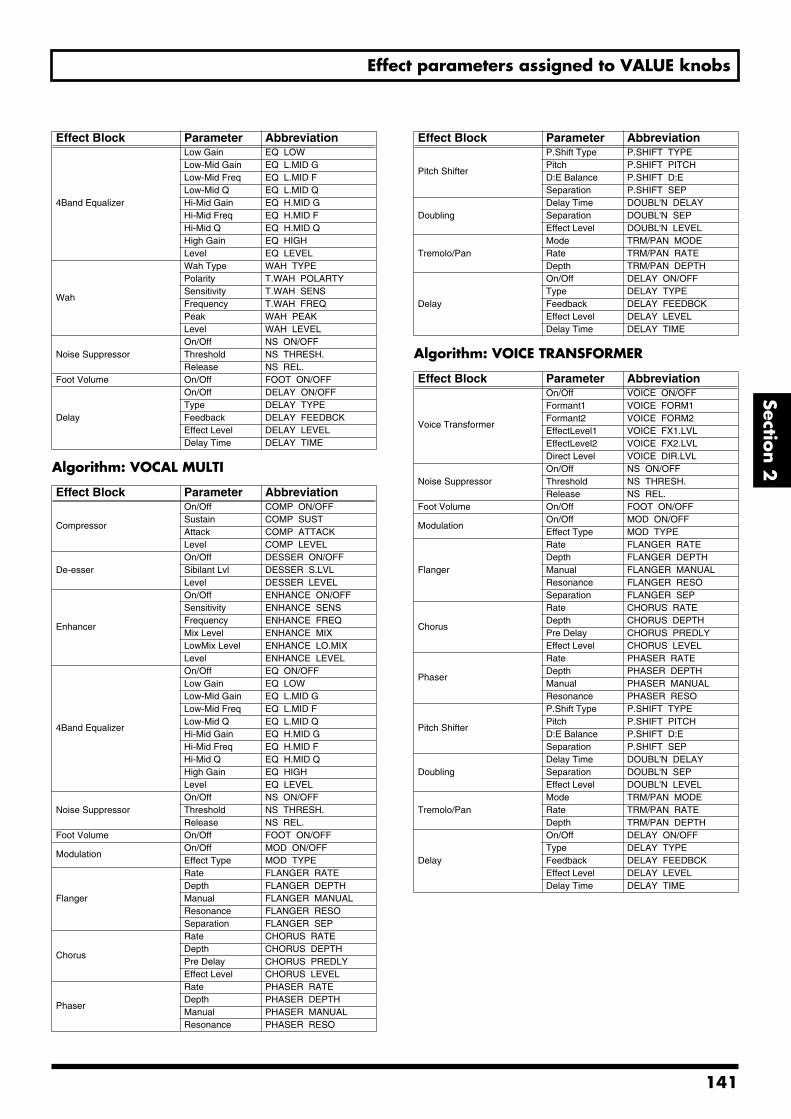
Effect parameters assigned to VALUE knobs
Section 2
Algorithm: VOCAL MULTIAlgorithm: VOICE TRANSFORMER
4Band Equalizer
Low Gain EQ LOWLow-Mid Gain EQ L.MID GLow-Mid Freq EQ L.MID FLow-Mid Q EQ L.MID QHi-Mid Gain EQ H.MID GHi-Mid Freq EQ H.MID FHi-Mid Q EQ H.MID QHigh Gain EQ HIGHLevel EQ LEVEL
Wah
Wah Type WAH TYPEPolarity T.WAH POLARTYSensitivity T.WAH SENSFrequency T.WAH FREQPeak WAH PEAKLevel WAH LEVEL
Noise SuppressorOn/Off NS ON/OFFThreshold NS THRESH.Release NS REL.
Foot Volume On/Off FOOT ON/OFF
Delay
On/Off DELAY ON/OFFType DELAY TYPEFeedback DELAY FEEDBCKEffect Level DELAY LEVELDelay Time DELAY TIME
Effect Block Parameter Abbreviation
Compressor
On/Off COMP ON/OFFSustain COMP SUSTAttack COMP ATTACKLevel COMP LEVEL
De-esserOn/Off DESSER ON/OFFSibilant Lvl DESSER S.LVLLevel DESSER LEVEL
Enhancer
On/Off ENHANCE ON/OFFSensitivity ENHANCE SENSFrequency ENHANCE FREQMix Level ENHANCE MIXLowMix Level ENHANCE LO.MIXLevel ENHANCE LEVEL
4Band Equalizer
On/Off EQ ON/OFFLow Gain EQ LOWLow-Mid Gain EQ L.MID GLow-Mid Freq EQ L.MID FLow-Mid Q EQ L.MID QHi-Mid Gain EQ H.MID GHi-Mid Freq EQ H.MID FHi-Mid Q EQ H.MID QHigh Gain EQ HIGHLevel EQ LEVEL
Noise SuppressorOn/Off NS ON/OFFThreshold NS THRESH.Release NS REL.
Foot Volume On/Off FOOT ON/OFF
ModulationOn/Off MOD ON/OFFEffect Type MOD TYPE
Flanger
Rate FLANGER RATEDepth FLANGER DEPTHManual FLANGER MANUALResonance FLANGER RESOSeparation FLANGER SEP
Chorus
Rate CHORUS RATEDepth CHORUS DEPTHPre Delay CHORUS PREDLYEffect Level CHORUS LEVEL
Phaser
Rate PHASER RATEDepth PHASER DEPTHManual PHASER MANUALResonance PHASER RESO
Effect Block Parameter Abbreviation
Pitch Shifter
P.Shift Type P.SHIFT TYPEPitch P.SHIFT PITCHD:E Balance P.SHIFT D:ESeparation P.SHIFT SEP
DoublingDelay Time DOUBL'N DELAYSeparation DOUBL'N SEPEffect Level DOUBL'N LEVEL
Tremolo/PanMode TRM/PAN MODERate TRM/PAN RATEDepth TRM/PAN DEPTH
Delay
On/Off DELAY ON/OFFType DELAY TYPEFeedback DELAY FEEDBCKEffect Level DELAY LEVELDelay Time DELAY TIME
Effect Block Parameter Abbreviation
Voice Transformer
On/Off VOICE ON/OFFFormant1 VOICE FORM1Formant2 VOICE FORM2EffectLevel1 VOICE FX1.LVLEffectLevel2 VOICE FX2.LVLDirect Level VOICE DIR.LVL
Noise SuppressorOn/Off NS ON/OFFThreshold NS THRESH.Release NS REL.
Foot Volume On/Off FOOT ON/OFF
ModulationOn/Off MOD ON/OFFEffect Type MOD TYPE
Flanger
Rate FLANGER RATEDepth FLANGER DEPTHManual FLANGER MANUALResonance FLANGER RESOSeparation FLANGER SEP
Chorus
Rate CHORUS RATEDepth CHORUS DEPTHPre Delay CHORUS PREDLYEffect Level CHORUS LEVEL
Phaser
Rate PHASER RATEDepth PHASER DEPTHManual PHASER MANUALResonance PHASER RESO
Pitch Shifter
P.Shift Type P.SHIFT TYPEPitch P.SHIFT PITCHD:E Balance P.SHIFT D:ESeparation P.SHIFT SEP
DoublingDelay Time DOUBL'N DELAYSeparation DOUBL'N SEPEffect Level DOUBL'N LEVEL
Tremolo/PanMode TRM/PAN MODERate TRM/PAN RATEDepth TRM/PAN DEPTH
Delay
On/Off DELAY ON/OFFType DELAY TYPEFeedback DELAY FEEDBCKEffect Level DELAY LEVELDelay Time DELAY TIME
Effect Block Parameter Abbreviation
141
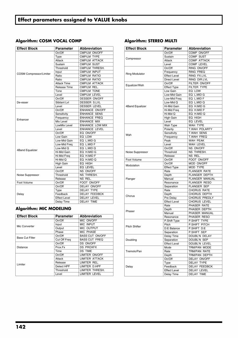
Effect parameters assigned to VALUE knobs
Algorithm: COSM VOCAL COMP
Algorithm: MIC MODELING
Algorithm: STEREO MULTI
Effect Block Parameter Abbreviation
COSM Compressor/Limiter
On/Off CMP/LM ON/OFFType CMP/LM TYPEAttack CMP/LM ATTACKSustain CMP/LM SUSTThreshold CMP/LM THRESH.Input CMP/LM INPUTRatio CMP/LM RATIORatio CMP/LM RATIOAttack Time CMP/LM ATTACKRelease Time CMP/LM REL.Tone CMP/LM TONELevel CMP/LM LEVEL
De-esserOn/Off DESSER ON/OFFSibilant Lvl DESSER S.LVLLevel DESSER LEVEL
Enhancer
On/Off ENHANCE ON/OFFSensitivity ENHANCE SENSFrequency ENHANCE FREQ Mix Level ENHANCE MIXLowMix Level ENHANCE LOW MIXLevel ENHANCE LEVEL
4Band Equalizer
On/Off EQ ON/OFF Low Gain EQ LOWLow-Mid Gain EQ L.MID GLow-Mid Freq EQ L.MID FLow-Mid Q EQ L.MID Q Hi-Mid Gain EQ H.MID GHi-Mid Freq EQ H.MID F Hi-Mid Q EQ H.MID QHigh Gain EQ HIGHLevel EQ LEVEL
Noise SuppressorOn/Off NS ON/OFFThreshold NS THRESH.Release NS REL.
Foot Volume On/Off FOOT ON/OFF
Delay
On/Off DELAY ON/OFFType DELAY TYPEFeedback DELAY FEEDBCKEffect Level DELAY LEVELDelay Time DELAY TIME
Effect Block Parameter Abbreviation
Mic Converter
On/Off MIC ON/OFFInput MIC INPUTOutput MIC OUTPUTPhase MIC PHASE
Bass Cut FilterOn/Off BASS CUT ON/OFFCut Off Freq BASS CUT FREQ
DistanceOn/Off DS ON/OFFProx.Fx DS PROXFXTime DS TIME
Limiter
On/Off LIMITER ON/OFFAttack LIMITER ATTACKRelease LIMITER REL.Detect HPF LIMITER D.HPFThreshold LIMITER THRESH.Level LIMITER LEVEL
Effect Block Parameter Abbreviation
Compressor
On/Off COMP ON/OFFSustain COMP SUSTAttack COMP ATTACKLevel COMP LEVEL
Ring Modulator
On/Off RING ON/OFFFrequency RING FREQEffect Level RING FX.LVLDirect Level RING DIR.LVL
Equalizer/WahOn/Off FILTER ON/OFFEffect Type FILTER TYPE
4Band Equalizer
Low Gain EQ LOWLow-Mid Gain EQ L.MID GLow-Mid Freq EQ L.MID FLow-Mid Q EQ L.MID QHi-Mid Gain EQ H.MID GHi-Mid Freq EQ H.MID FHi-Mid Q EQ H.MID QHigh Gain EQ HIGHLevel EQ LEVEL
Wah
Wah Type WAH TYPEPolarity T.WAH POLARTYSensitivity T.WAH SENSFrequency T.WAH FREQPeak WAH PEAKLevel WAH LEVEL
Noise SuppressorOn/Off NS ON/OFFThreshold NS THRESH.Release NS REL.
Foot Volume On/Off FOOT ON/OFF
ModulationOn/Off MOD ON/OFFEffect Type MOD TYPE
Flanger
Rate FLANGER RATEDepth FLANGER DEPTHManual FLANGER MANUALResonance FLANGER RESOSeparation FLANGER SEP
Chorus
Rate CHORUS RATEDepth CHORUS DEPTHPre Delay CHORUS PREDLYEffect Level CHORUS LEVEL
Phaser
Rate PHASER RATEDepth PHASER DEPTHManual PHASER MANUALResonance PHASER RESO
Pitch Shifter
P.Shift Type P.SHIFT TYPEPitch P.SHIFT PITCHD:E Balance P.SHIFT D:ESeparation P.SHIFT SEP
DoublingDelay Time DOUBL'N DELAYSeparation DOUBL'N SEPEffect Level DOUBL'N LEVEL
Tremolo/PanMode TRM/PAN MODERate TRM/PAN RATEDepth TRM/PAN DEPTH
Delay
On/Off DELAY ON/OFFType DELAY TYPEFeedback DELAY FEEDBCKEffect Level DELAY LEVELDelay Time DELAY TIME
142
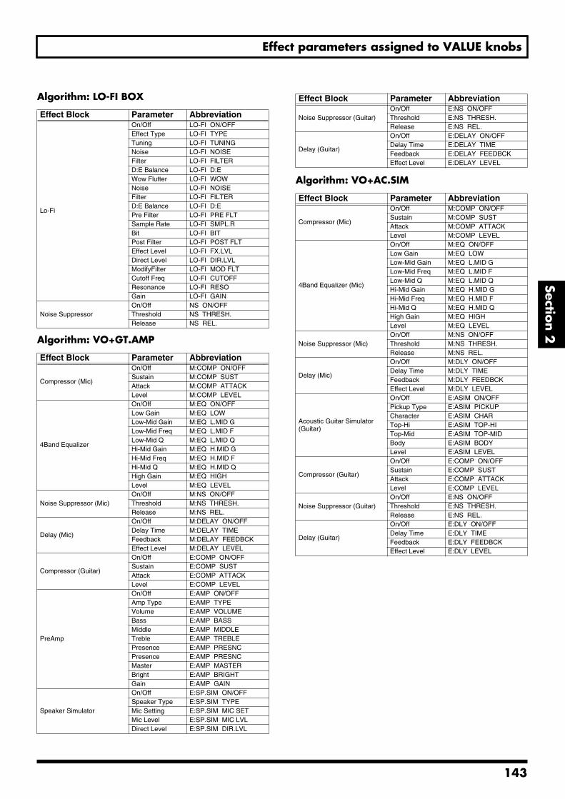
Effect parameters assigned to VALUE knobs
Section 2
Algorithm: LO-FI BOX
Algorithm: VO+GT.AMP
Algorithm: VO+AC.SIM
Effect Block Parameter Abbreviation
Lo-Fi
On/Off LO-FI ON/OFFEffect Type LO-FI TYPETuning LO-FI TUNINGNoise LO-FI NOISEFilter LO-FI FILTERD:E Balance LO-FI D:EWow Flutter LO-FI WOWNoise LO-FI NOISEFilter LO-FI FILTERD:E Balance LO-FI D:EPre Filter LO-FI PRE FLTSample Rate LO-FI SMPL.RBit LO-FI BITPost Filter LO-FI POST FLTEffect Level LO-FI FX.LVLDirect Level LO-FI DIR.LVLModifyFilter LO-FI MOD FLTCutoff Freq LO-FI CUTOFFResonance LO-FI RESOGain LO-FI GAIN
Noise SuppressorOn/Off NS ON/OFFThreshold NS THRESH.Release NS REL.
Effect Block Parameter Abbreviation
Compressor (Mic)
On/Off M:COMP ON/OFFSustain M:COMP SUSTAttack M:COMP ATTACKLevel M:COMP LEVEL
4Band Equalizer
On/Off M:EQ ON/OFFLow Gain M:EQ LOWLow-Mid Gain M:EQ L.MID GLow-Mid Freq M:EQ L.MID FLow-Mid Q M:EQ L.MID QHi-Mid Gain M:EQ H.MID GHi-Mid Freq M:EQ H.MID FHi-Mid Q M:EQ H.MID QHigh Gain M:EQ HIGHLevel M:EQ LEVEL
Noise Suppressor (Mic)On/Off M:NS ON/OFFThreshold M:NS THRESH.Release M:NS REL.
Delay (Mic)
On/Off M:DELAY ON/OFFDelay Time M:DELAY TIMEFeedback M:DELAY FEEDBCKEffect Level M:DELAY LEVEL
Compressor (Guitar)
On/Off E:COMP ON/OFFSustain E:COMP SUSTAttack E:COMP ATTACKLevel E:COMP LEVEL
PreAmp
On/Off E:AMP ON/OFFAmp Type E:AMP TYPEVolume E:AMP VOLUMEBass E:AMP BASSMiddle E:AMP MIDDLETreble E:AMP TREBLEPresence E:AMP PRESNCPresence E:AMP PRESNCMaster E:AMP MASTERBright E:AMP BRIGHTGain E:AMP GAIN
Speaker Simulator
On/Off E:SP.SIM ON/OFFSpeaker Type E:SP.SIM TYPEMic Setting E:SP.SIM MIC SETMic Level E:SP.SIM MIC LVLDirect Level E:SP.SIM DIR.LVL
Noise Suppressor (Guitar)On/Off E:NS ON/OFFThreshold E:NS THRESH.Release E:NS REL.
Delay (Guitar)
On/Off E:DELAY ON/OFFDelay Time E:DELAY TIMEFeedback E:DELAY FEEDBCKEffect Level E:DELAY LEVEL
Effect Block Parameter Abbreviation
Compressor (Mic)
On/Off M:COMP ON/OFFSustain M:COMP SUSTAttack M:COMP ATTACKLevel M:COMP LEVEL
4Band Equalizer (Mic)
On/Off M:EQ ON/OFFLow Gain M:EQ LOWLow-Mid Gain M:EQ L.MID GLow-Mid Freq M:EQ L.MID FLow-Mid Q M:EQ L.MID QHi-Mid Gain M:EQ H.MID GHi-Mid Freq M:EQ H.MID FHi-Mid Q M:EQ H.MID QHigh Gain M:EQ HIGHLevel M:EQ LEVEL
Noise Suppressor (Mic)On/Off M:NS ON/OFFThreshold M:NS THRESH.Release M:NS REL.
Delay (Mic)
On/Off M:DLY ON/OFFDelay Time M:DLY TIMEFeedback M:DLY FEEDBCKEffect Level M:DLY LEVEL
Acoustic Guitar Simulator (Guitar)
On/Off E:ASIM ON/OFFPickup Type E:ASIM PICKUPCharacter E:ASIM CHARTop-Hi E:ASIM TOP-HITop-Mid E:ASIM TOP-MIDBody E:ASIM BODYLevel E:ASIM LEVEL
Compressor (Guitar)
On/Off E:COMP ON/OFFSustain E:COMP SUSTAttack E:COMP ATTACKLevel E:COMP LEVEL
Noise Suppressor (Guitar)On/Off E:NS ON/OFFThreshold E:NS THRESH.Release E:NS REL.
Delay (Guitar)
On/Off E:DLY ON/OFFDelay Time E:DLY TIMEFeedback E:DLY FEEDBCKEffect Level E:DLY LEVEL
Effect Block Parameter Abbreviation
143
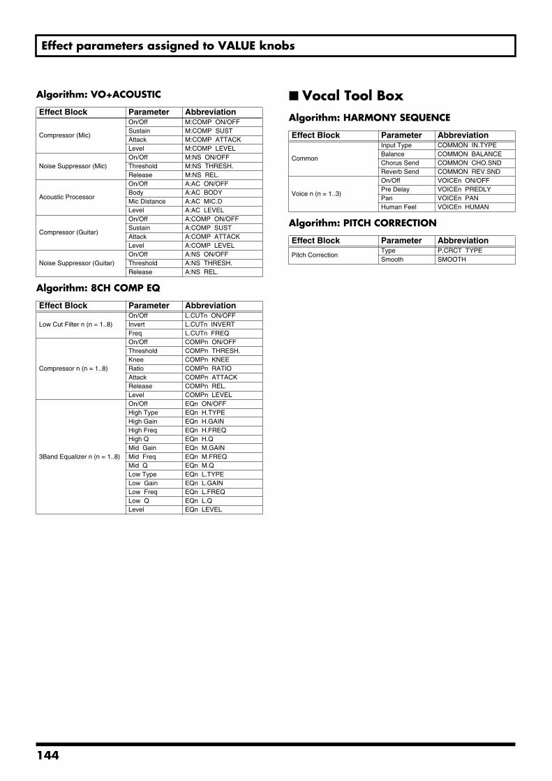
Effect parameters assigned to VALUE knobs
Algorithm: VO+ACOUSTIC
Algorithm: 8CH COMP EQ
Vocal Tool BoxAlgorithm: HARMONY SEQUENCE
Algorithm: PITCH CORRECTION
Effect Block Parameter Abbreviation
Compressor (Mic)
On/Off M:COMP ON/OFFSustain M:COMP SUSTAttack M:COMP ATTACKLevel M:COMP LEVEL
Noise Suppressor (Mic)On/Off M:NS ON/OFFThreshold M:NS THRESH.Release M:NS REL.
Acoustic Processor
On/Off A:AC ON/OFFBody A:AC BODYMic Distance A:AC MIC.DLevel A:AC LEVEL
Compressor (Guitar)
On/Off A:COMP ON/OFFSustain A:COMP SUSTAttack A:COMP ATTACKLevel A:COMP LEVEL
Noise Suppressor (Guitar)On/Off A:NS ON/OFFThreshold A:NS THRESH.Release A:NS REL.
Effect Block Parameter Abbreviation
Low Cut Filter n (n = 1..8)On/Off L.CUTn ON/OFFInvert L.CUTn INVERTFreq L.CUTn FREQ
Compressor n (n = 1..8)
On/Off COMPn ON/OFFThreshold COMPn THRESH.Knee COMPn KNEERatio COMPn RATIOAttack COMPn ATTACKRelease COMPn REL.Level COMPn LEVEL
3Band Equalizer n (n = 1..8)
On/Off EQn ON/OFFHigh Type EQn H.TYPEHigh Gain EQn H.GAINHigh Freq EQn H.FREQHigh Q EQn H.QMid Gain EQn M.GAINMid Freq EQn M.FREQMid Q EQn M.QLow Type EQn L.TYPELow Gain EQn L.GAINLow Freq EQn L.FREQLow Q EQn L.QLevel EQn LEVEL
Effect Block Parameter Abbreviation
Common
Input Type COMMON IN.TYPEBalance COMMON BALANCEChorus Send COMMON CHO.SNDReverb Send COMMON REV.SND
Voice n (n = 1..3)
On/Off VOICEn ON/OFFPre Delay VOICEn PREDLYPan VOICEn PANHuman Feel VOICEn HUMAN
Effect Block Parameter Abbreviation
Pitch CorrectionType P.CRCT TYPESmooth SMOOTH
144
Section 3 Using Rhythm
Section 3Using Rhythm
145
1
Makeup of Drum/Bass/Loop Phrase
The BR-1600CD's programmable rhythm section comprises tracks for Drum Patterns, Bass Patterns, and Loop Phrases. When used, you will be able to have your favorite rhythms automatically played over and over to provide a convenient guide for recording and practicing. In addition, you can arrange different rhythm performances for the intro, the verse, the chorus, and other sections in a sequence that matches your song, and this makes it much easier to produce great-sounding demos (Rhythm Arrangement, p. 148).
This chapter will provide a description of Drum Patterns, Bass Patterns, and Loop Phrases. In addition, rhythm arrangements will also be described.
DrumsOn the BR-1600CD, tracks 15/16 are designated as the drum tracks, and can be used to automatically play drum parts. By selecting realistic drums sounds from the internal PCM drum samples and by setting a suitable tempo, you can have the BR-1600CD automatically play drum parts that are perfect for making demo songs.
Drum tracks usually contain a variety of percussion instrument sounds, such as kick drums, snares, hi-hats, etc. The BR-1600CD features a broad variety of these sounds, which are organized into sets called “drum kits.” There are nine drum kits in all on the BR-1600CD, and these reflect a wide range of different musical styles.
Furthermore, drum tracks can also be made to automatically play basic drum performances of one or several measures in a repetitive fashion.
At the time of purchase, the BR-1600CD contains 600 preset drum patterns, which cannot be overwritten. In addition, the BR-1600CD can also store 999 user drum patterns, which can be used in any song, and 999 song drum patterns, which are stored together with a specific song. User drum patches and song drum patches can be overwritten.
• For details on how drums are actually used, refer to “Using drums” (p. 149).
• Drums can only be used when Track 15/16 has been set up as a drum track using its track type setting (p. 149).
• Up to five individual drums sounds can be played simultaneously. If an attempt is made to play more than five such sounds at any one time, any previous sounds that are still being played will be silenced before new sounds are played.
BassOn the BR-1600CD, tracks 13/14 are designated as the bass tracks, and can be used to automatically play bass parts. By selecting realistic bass sounds from the internal PCM bass samples and by setting a suitable tempo, you can have the BR-1600CD automatically play bass parts that are perfect for making demo songs.
The BR-1600CD comes complete with twelve different bass guitar sounds including fingered, picked, and slap bass, thus allowing you to recreate a wide range of different musical styles and genres.
In addition, bass tracks can also be made to automatically play basic bass performances in a repetitive fashion. The data used to create these basic bass performances is known as a bass pattern.
At the time of purchase, the BR-1600CD contains 583 preset bass patterns, and these cannot be overwritten. In addition, the BR-1600CD can also store 999 user bass patterns that can be used in any song and 999 song bass patterns that are saved together with a specific song. User bass patterns and song bass patterns can be overwritten.
• For details on how bass are actually used, refer to “Using bass” (p. 163).
• Bass can only be used when Track 13/14 has been set up as a bass track using its track type setting (p. 163).
• The BR-1600CD uses mono bass sounds.
• Only one sound can be played simultaneously. If an attempt is made to play more than two such sounds at any one time, any previous sounds that are still being played will be silenced before new sound is played.
46
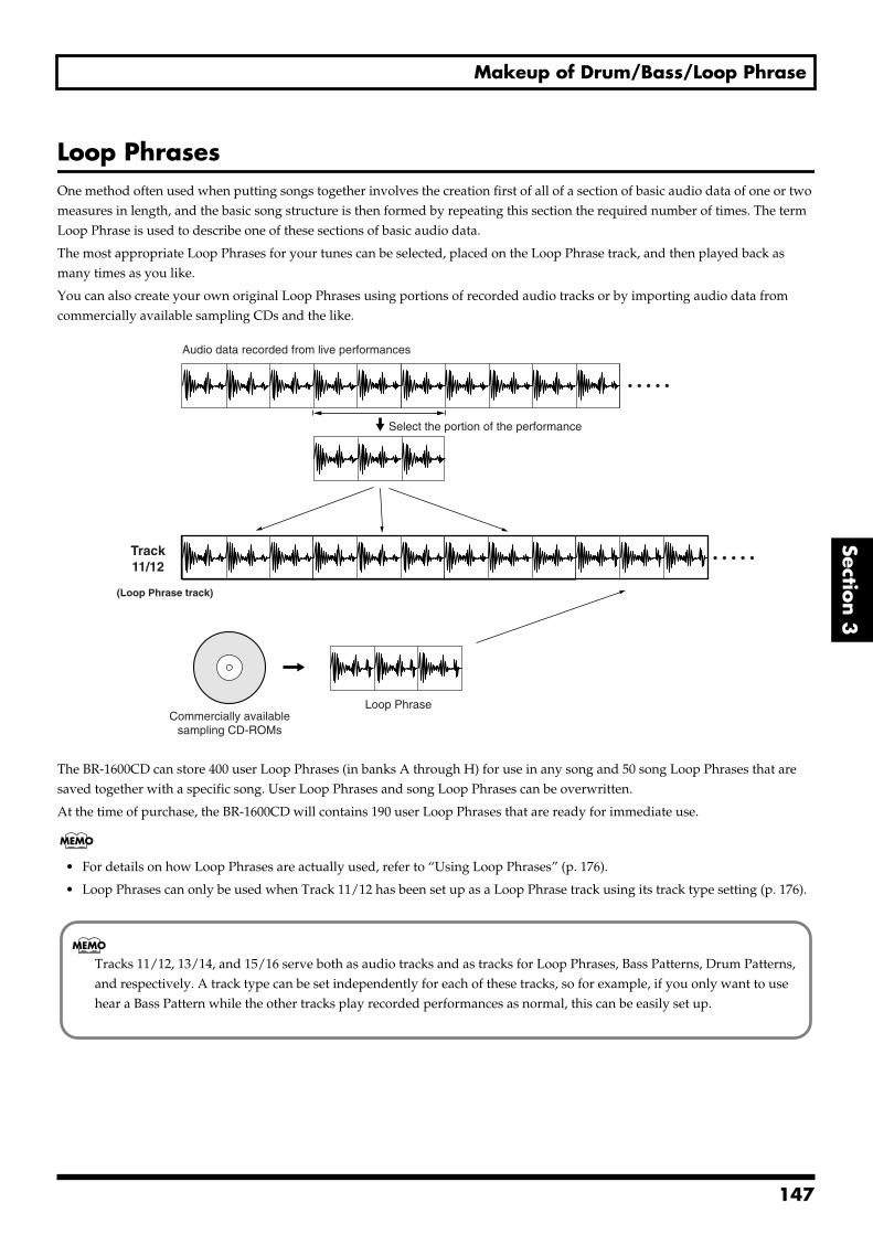
Makeup of Drum/Bass/Loop Phrase
Section 3
Loop PhrasesOne method often used when putting songs together involves the creation first of all of a section of basic audio data of one or two measures in length, and the basic song structure is then formed by repeating this section the required number of times. The term Loop Phrase is used to describe one of these sections of basic audio data.
The most appropriate Loop Phrases for your tunes can be selected, placed on the Loop Phrase track, and then played back as many times as you like.
You can also create your own original Loop Phrases using portions of recorded audio tracks or by importing audio data from commercially available sampling CDs and the like.fig.20-000
The BR-1600CD can store 400 user Loop Phrases (in banks A through H) for use in any song and 50 song Loop Phrases that are saved together with a specific song. User Loop Phrases and song Loop Phrases can be overwritten.
At the time of purchase, the BR-1600CD will contains 190 user Loop Phrases that are ready for immediate use.
• For details on how Loop Phrases are actually used, refer to “Using Loop Phrases” (p. 176).
• Loop Phrases can only be used when Track 11/12 has been set up as a Loop Phrase track using its track type setting (p. 176).
Audio data recorded from live performances
Select the portion of the performance
Track11/12
(Loop Phrase track)
Commercially availablesampling CD-ROMs
Loop Phrase
Tracks 11/12, 13/14, and 15/16 serve both as audio tracks and as tracks for Loop Phrases, Bass Patterns, Drum Patterns, and respectively. A track type can be set independently for each of these tracks, so for example, if you only want to use hear a Bass Pattern while the other tracks play recorded performances as normal, this can be easily set up.
147
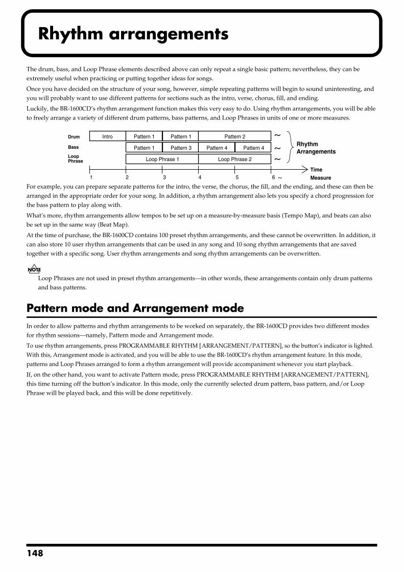
1
Rhythm arrangements
The drum, bass, and Loop Phrase elements described above can only repeat a single basic pattern; nevertheless, they can be extremely useful when practicing or putting together ideas for songs.
Once you have decided on the structure of your song, however, simple repeating patterns will begin to sound uninteresting, and you will probably want to use different patterns for sections such as the intro, verse, chorus, fill, and ending.
Luckily, the BR-1600CD’s rhythm arrangement function makes this very easy to do. Using rhythm arrangements, you will be able to freely arrange a variety of different drum patterns, bass patterns, and Loop Phrases in units of one or more measures.fig.20-001
For example, you can prepare separate patterns for the intro, the verse, the chorus, the fill, and the ending, and these can then be arranged in the appropriate order for your song. In addition, a rhythm arrangement also lets you specify a chord progression for the bass pattern to play along with.
What’s more, rhythm arrangements allow tempos to be set up on a measure-by-measure basis (Tempo Map), and beats can also be set up in the same way (Beat Map).
At the time of purchase, the BR-1600CD contains 100 preset rhythm arrangements, and these cannot be overwritten. In addition, it can also store 10 user rhythm arrangements that can be used in any song and 10 song rhythm arrangements that are saved together with a specific song. User rhythm arrangements and song rhythm arrangements can be overwritten.
Loop Phrases are not used in preset rhythm arrangements—in other words, these arrangements contain only drum patterns and bass patterns.
Pattern mode and Arrangement modeIn order to allow patterns and rhythm arrangements to be worked on separately, the BR-1600CD provides two different modes for rhythm sessions—namely, Pattern mode and Arrangement mode.
To use rhythm arrangements, press PROGRAMMABLE RHYTHM [ARRANGEMENT/PATTERN], so the button’s indicator is lighted. With this, Arrangement mode is activated, and you will be able to use the BR-1600CD’s rhythm arrangement feature. In this mode, patterns and Loop Phrases arranged to form a rhythm arrangement will provide accompaniment whenever you start playback.
If, on the other hand, you want to activate Pattern mode, press PROGRAMMABLE RHYTHM [ARRANGEMENT/PATTERN], this time turning off the button’s indicator. In this mode, only the currently selected drum pattern, bass pattern, and/or Loop Phrase will be played back, and this will be done repetitively.
1 2 3 4 5 6Time
Measure
IntroDrum
Bass
LoopPhrase
Pattern 1 Pattern 1
Pattern 1 Pattern 3 Pattern 4 Pattern 4
Pattern 2
Loop Phrase 2Loop Phrase 1
RhythmArrangements
48
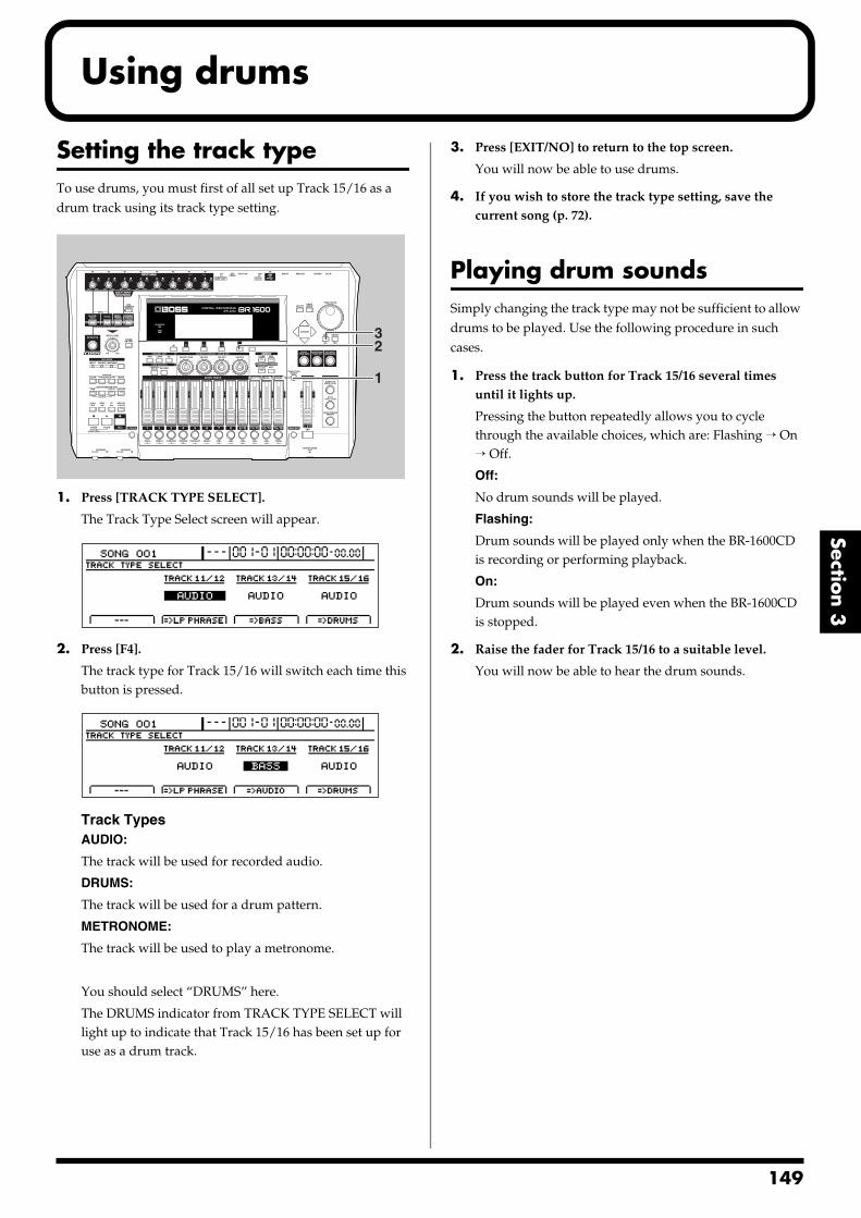
Using drums
Section 3
Setting the track typeTo use drums, you must first of all set up Track 15/16 as a drum track using its track type setting.fig.20-002
1. Press [TRACK TYPE SELECT].
The Track Type Select screen will appear.fig.20-003d
2. Press [F4].
The track type for Track 15/16 will switch each time this button is pressed.
fig.20-004d
Track TypesAUDIO:
The track will be used for recorded audio.
DRUMS:
The track will be used for a drum pattern.
METRONOME:
The track will be used to play a metronome.
You should select “DRUMS” here.
The DRUMS indicator from TRACK TYPE SELECT will light up to indicate that Track 15/16 has been set up for use as a drum track.
3. Press [EXIT/NO] to return to the top screen.
You will now be able to use drums.
4. If you wish to store the track type setting, save the current song (p. 72).
Playing drum soundsSimply changing the track type may not be sufficient to allow drums to be played. Use the following procedure in such cases.
1. Press the track button for Track 15/16 several times until it lights up.
Pressing the button repeatedly allows you to cycle through the available choices, which are: Flashing → On → Off.
Off:
No drum sounds will be played.
Flashing:
Drum sounds will be played only when the BR-1600CD is recording or performing playback.
On:
Drum sounds will be played even when the BR-1600CD is stopped.
2. Raise the fader for Track 15/16 to a suitable level.
You will now be able to hear the drum sounds.
1
32
149
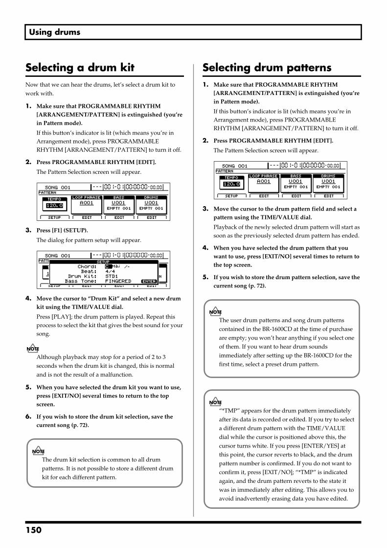
Using drums
Selecting a drum kitNow that we can hear the drums, let’s select a drum kit to work with.
1. Make sure that PROGRAMMABLE RHYTHM [ARRANGEMENT/PATTERN] is extinguished (you’re in Pattern mode).
If this button’s indicator is lit (which means you’re in Arrangement mode), press PROGRAMMABLE RHYTHM [ARRANGEMENT/PATTERN] to turn it off.
2. Press PROGRAMMABLE RHYTHM [EDIT].
The Pattern Selection screen will appear.fig.20-005d
3. Press [F1] (SETUP).
The dialog for pattern setup will appear.fig.20-006d
4. Move the cursor to “Drum Kit” and select a new drum kit using the TIME/VALUE dial.
Press [PLAY]; the drum pattern is played. Repeat this process to select the kit that gives the best sound for your song.
Although playback may stop for a period of 2 to 3 seconds when the drum kit is changed, this is normal and is not the result of a malfunction.
5. When you have selected the drum kit you want to use, press [EXIT/NO] several times to return to the top screen.
6. If you wish to store the drum kit selection, save the current song (p. 72).
Selecting drum patterns1. Make sure that PROGRAMMABLE RHYTHM
[ARRANGEMENT/PATTERN] is extinguished (you’re in Pattern mode).
If this button’s indicator is lit (which means you’re in Arrangement mode), press PROGRAMMABLE RHYTHM [ARRANGEMENT/PATTERN] to turn it off.
2. Press PROGRAMMABLE RHYTHM [EDIT].
The Pattern Selection screen will appear.fig.20-005d
3. Move the cursor to the drum pattern field and select a pattern using the TIME/VALUE dial.
Playback of the newly selected drum pattern will start as soon as the previously selected drum pattern has ended.
4. When you have selected the drum pattern that you want to use, press [EXIT/NO] several times to return to the top screen.
5. If you wish to store the drum pattern selection, save the current song (p. 72).
The drum kit selection is common to all drum patterns. It is not possible to store a different drum kit for each different pattern.
The user drum patterns and song drum patterns contained in the BR-1600CD at the time of purchase are empty; you won’t hear anything if you select one of them. If you want to hear drum sounds immediately after setting up the BR-1600CD for the first time, select a preset drum pattern.
“*TMP” appears for the drum pattern immediately after its data is recorded or edited. If you try to select a different drum pattern with the TIME/VALUE dial while the cursor is positioned above this, the cursor turns white. If you press [ENTER/YES] at this point, the cursor reverts to black, and the drum pattern number is confirmed. If you do not want to confirm it, press [EXIT/NO]; “*TMP” is indicated again, and the drum pattern reverts to the state it was in immediately after editing. This allows you to avoid inadvertently erasing data you have edited.
150
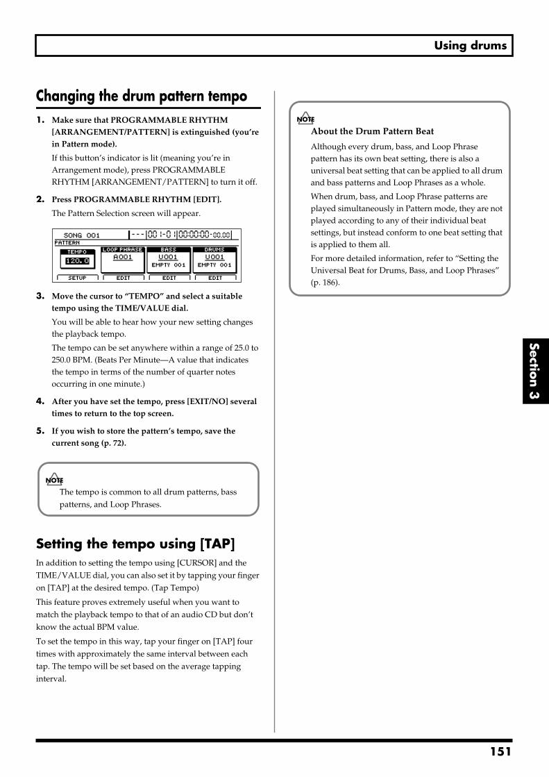
Using drums
Section 3
Changing the drum pattern tempo1. Make sure that PROGRAMMABLE RHYTHM
[ARRANGEMENT/PATTERN] is extinguished (you’re in Pattern mode).
If this button’s indicator is lit (meaning you’re in Arrangement mode), press PROGRAMMABLE RHYTHM [ARRANGEMENT/PATTERN] to turn it off.
2. Press PROGRAMMABLE RHYTHM [EDIT].
The Pattern Selection screen will appear.fig.20-005d
3. Move the cursor to “TEMPO” and select a suitable tempo using the TIME/VALUE dial.
You will be able to hear how your new setting changes the playback tempo.
The tempo can be set anywhere within a range of 25.0 to 250.0 BPM. (Beats Per Minute—A value that indicates the tempo in terms of the number of quarter notes occurring in one minute.)
4. After you have set the tempo, press [EXIT/NO] several times to return to the top screen.
5. If you wish to store the pattern’s tempo, save the current song (p. 72).
Setting the tempo using [TAP]In addition to setting the tempo using [CURSOR] and the TIME/VALUE dial, you can also set it by tapping your finger on [TAP] at the desired tempo. (Tap Tempo)
This feature proves extremely useful when you want to match the playback tempo to that of an audio CD but don’t know the actual BPM value.
To set the tempo in this way, tap your finger on [TAP] four times with approximately the same interval between each tap. The tempo will be set based on the average tapping interval.
The tempo is common to all drum patterns, bass patterns, and Loop Phrases.
About the Drum Pattern Beat
Although every drum, bass, and Loop Phrase pattern has its own beat setting, there is also a universal beat setting that can be applied to all drum and bass patterns and Loop Phrases as a whole.
When drum, bass, and Loop Phrase patterns are played simultaneously in Pattern mode, they are not played according to any of their individual beat settings, but instead conform to one beat setting that is applied to them all.
For more detailed information, refer to “Setting the Universal Beat for Drums, Bass, and Loop Phrases” (p. 186).
151
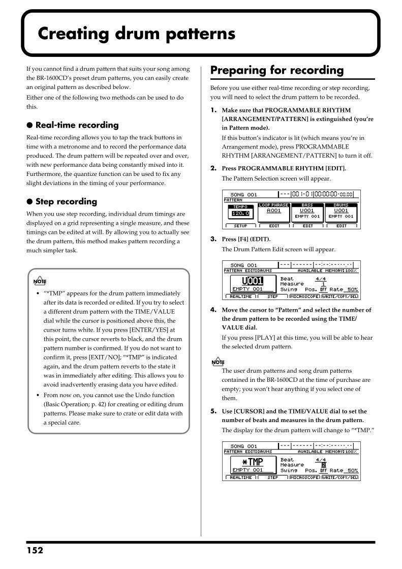
1
Creating drum patterns
If you cannot find a drum pattern that suits your song among the BR-1600CD’s preset drum patterns, you can easily create an original pattern as described below.
Either one of the following two methods can be used to do this.
Real-time recordingReal-time recording allows you to tap the track buttons in time with a metronome and to record the performance data produced. The drum pattern will be repeated over and over, with new performance data being constantly mixed into it. Furthermore, the quantize function can be used to fix any slight deviations in the timing of your performance.
Step recordingWhen you use step recording, individual drum timings are displayed on a grid representing a single measure, and these timings can be edited at will. By allowing you to actually see the drum pattern, this method makes pattern recording a much simpler task.
Preparing for recordingBefore you use either real-time recording or step recording, you will need to select the drum pattern to be recorded.
1. Make sure that PROGRAMMABLE RHYTHM [ARRANGEMENT/PATTERN] is extinguished (you’re in Pattern mode).
If this button’s indicator is lit (which means you’re in Arrangement mode), press PROGRAMMABLE RHYTHM [ARRANGEMENT/PATTERN] to turn it off.
2. Press PROGRAMMABLE RHYTHM [EDIT].
The Pattern Selection screen will appear.fig.20-005d
3. Press [F4] (EDIT).
The Drum Pattern Edit screen will appear.fig.20-010d
4. Move the cursor to “Pattern” and select the number of the drum pattern to be recorded using the TIME/VALUE dial.
If you press [PLAY] at this time, you will be able to hear the selected drum pattern.
The user drum patterns and song drum patterns contained in the BR-1600CD at the time of purchase are empty; you won’t hear anything if you select one of them.
5. Use [CURSOR] and the TIME/VALUE dial to set the number of beats and measures in the drum pattern.
The display for the drum pattern will change to “*TMP.”fig.20-010ad
• “*TMP” appears for the drum pattern immediately after its data is recorded or edited. If you try to select a different drum pattern with the TIME/VALUE dial while the cursor is positioned above this, the cursor turns white. If you press [ENTER/YES] at this point, the cursor reverts to black, and the drum pattern number is confirmed. If you do not want to confirm it, press [EXIT/NO]; “*TMP” is indicated again, and the drum pattern reverts to the state it was in immediately after editing. This allows you to avoid inadvertently erasing data you have edited.
• From now on, you cannot use the Undo function (Basic Operation; p. 42) for creating or editing drum patterns. Please make sure to crate or edit data with a special care.
52
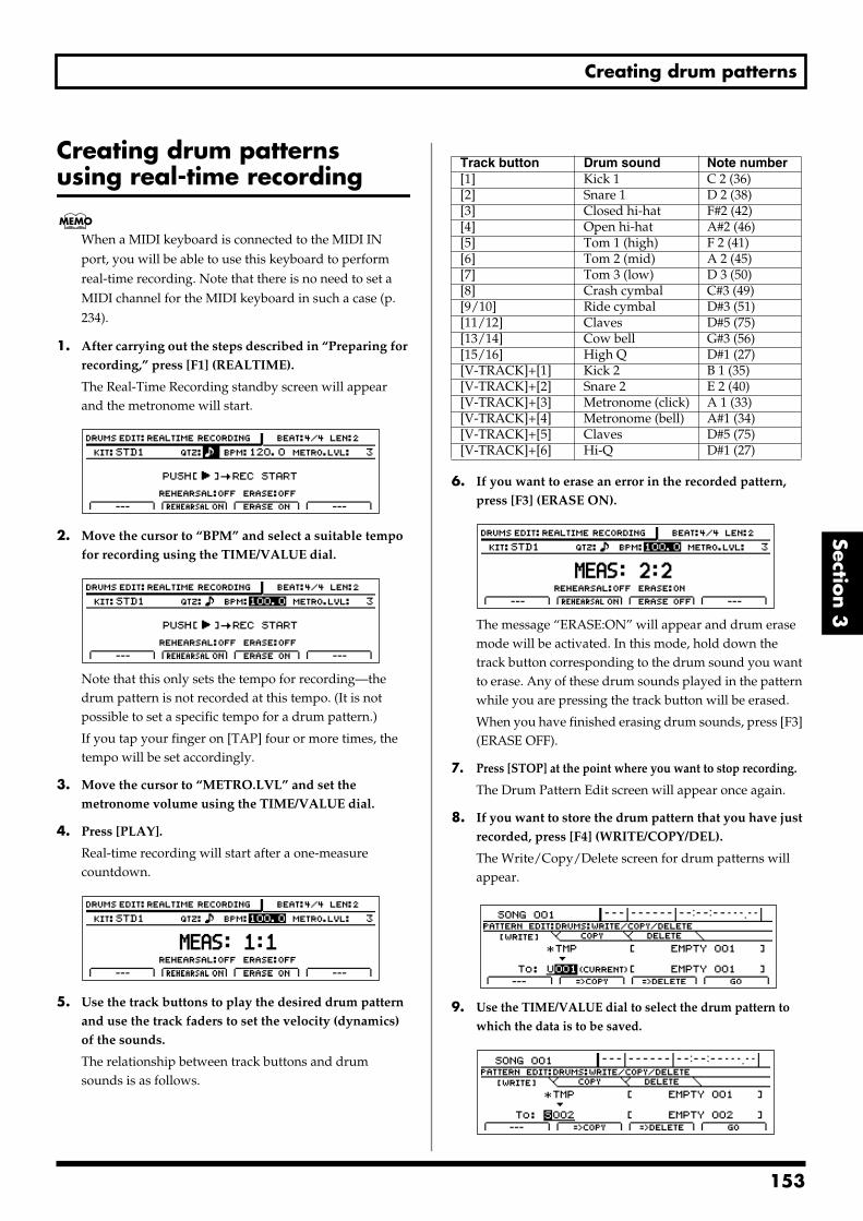
Creating drum patterns
Section 3
Creating drum patterns using real-time recording
When a MIDI keyboard is connected to the MIDI IN port, you will be able to use this keyboard to perform real-time recording. Note that there is no need to set a MIDI channel for the MIDI keyboard in such a case (p. 234).
1. After carrying out the steps described in “Preparing for recording,” press [F1] (REALTIME).
The Real-Time Recording standby screen will appear and the metronome will start.
fig.20-011d
2. Move the cursor to “BPM” and select a suitable tempo for recording using the TIME/VALUE dial.
fig.20-011ad
Note that this only sets the tempo for recording—the drum pattern is not recorded at this tempo. (It is not possible to set a specific tempo for a drum pattern.)
If you tap your finger on [TAP] four or more times, the tempo will be set accordingly.
3. Move the cursor to “METRO.LVL” and set the metronome volume using the TIME/VALUE dial.
4. Press [PLAY].
Real-time recording will start after a one-measure countdown.
fig.20-012d
5. Use the track buttons to play the desired drum pattern and use the track faders to set the velocity (dynamics) of the sounds.
The relationship between track buttons and drum sounds is as follows.
6. If you want to erase an error in the recorded pattern, press [F3] (ERASE ON).
fig.20-012ad
The message “ERASE:ON” will appear and drum erase mode will be activated. In this mode, hold down the track button corresponding to the drum sound you want to erase. Any of these drum sounds played in the pattern while you are pressing the track button will be erased.
When you have finished erasing drum sounds, press [F3] (ERASE OFF).
7. Press [STOP] at the point where you want to stop recording.
The Drum Pattern Edit screen will appear once again.
8. If you want to store the drum pattern that you have just recorded, press [F4] (WRITE/COPY/DEL).
The Write/Copy/Delete screen for drum patterns will appear.
fig.20-013d
9. Use the TIME/VALUE dial to select the drum pattern to which the data is to be saved.
fig.20-013ad
Track button Drum sound Note number[1] Kick 1 C 2 (36)[2] Snare 1 D 2 (38)[3] Closed hi-hat F#2 (42)[4] Open hi-hat A#2 (46)[5] Tom 1 (high) F 2 (41)[6] Tom 2 (mid) A 2 (45)[7] Tom 3 (low) D 3 (50)[8] Crash cymbal C#3 (49)[9/10] Ride cymbal D#3 (51)[11/12] Claves D#5 (75)[13/14] Cow bell G#3 (56)[15/16] High Q D#1 (27)[V-TRACK]+[1] Kick 2 B 1 (35)[V-TRACK]+[2] Snare 2 E 2 (40)[V-TRACK]+[3] Metronome (click) A 1 (33)[V-TRACK]+[4] Metronome (bell) A#1 (34)[V-TRACK]+[5] Claves D#5 (75)[V-TRACK]+[6] Hi-Q D#1 (27)
153
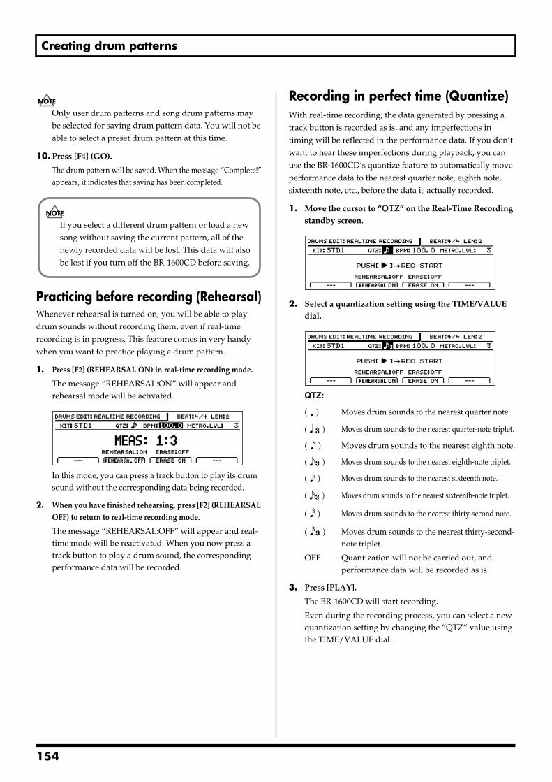
Creating drum patterns
Only user drum patterns and song drum patterns may be selected for saving drum pattern data. You will not be able to select a preset drum pattern at this time.
10. Press [F4] (GO).
The drum pattern will be saved. When the message “Complete!” appears, it indicates that saving has been completed.
Practicing before recording (Rehearsal)Whenever rehearsal is turned on, you will be able to play drum sounds without recording them, even if real-time recording is in progress. This feature comes in very handy when you want to practice playing a drum pattern.
1. Press [F2] (REHEARSAL ON) in real-time recording mode.
The message “REHEARSAL:ON” will appear and rehearsal mode will be activated.
fig.20-014d
In this mode, you can press a track button to play its drum sound without the corresponding data being recorded.
2. When you have finished rehearsing, press [F2] (REHEARSAL OFF) to return to real-time recording mode.
The message “REHEARSAL:OFF” will appear and real-time mode will be reactivated. When you now press a track button to play a drum sound, the corresponding performance data will be recorded.
Recording in perfect time (Quantize)With real-time recording, the data generated by pressing a track button is recorded as is, and any imperfections in timing will be reflected in the performance data. If you don’t want to hear these imperfections during playback, you can use the BR-1600CD’s quantize feature to automatically move performance data to the nearest quarter note, eighth note, sixteenth note, etc., before the data is actually recorded.
1. Move the cursor to “QTZ” on the Real-Time Recording standby screen.
fig.20-015d
2. Select a quantization setting using the TIME/VALUE dial.
fig.20-015ad
QTZ:
( ) Moves drum sounds to the nearest quarter note.
( ) Moves drum sounds to the nearest quarter-note triplet.
( ) Moves drum sounds to the nearest eighth note.
( ) Moves drum sounds to the nearest eighth-note triplet.
( ) Moves drum sounds to the nearest sixteenth note.
( ) Moves drum sounds to the nearest sixteenth-note triplet.
( ) Moves drum sounds to the nearest thirty-second note.
( ) Moves drum sounds to the nearest thirty-second-note triplet.
OFF Quantization will not be carried out, and performance data will be recorded as is.
3. Press [PLAY].
The BR-1600CD will start recording.
Even during the recording process, you can select a new quantization setting by changing the “QTZ” value using the TIME/VALUE dial.
If you select a different drum pattern or load a new song without saving the current pattern, all of the newly recorded data will be lost. This data will also be lost if you turn off the BR-1600CD before saving.
154
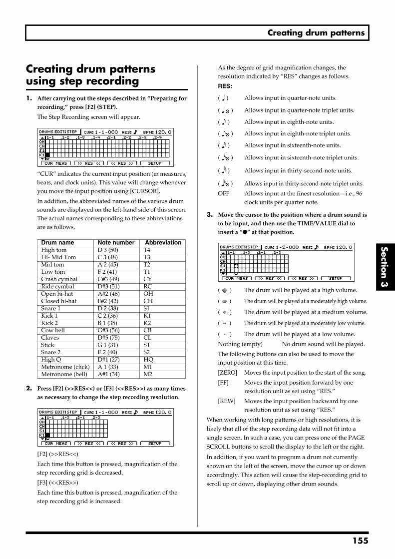
Creating drum patterns
Section 3
Creating drum patterns using step recording1. After carrying out the steps described in “Preparing for
recording,” press [F2] (STEP).
The Step Recording screen will appear.fig.20-016d
“CUR” indicates the current input position (in measures, beats, and clock units). This value will change whenever you move the input position using [CURSOR].
In addition, the abbreviated names of the various drum sounds are displayed on the left-hand side of this screen. The actual names corresponding to these abbreviations are as follows.
2. Press [F2] (>>RES<<) or [F3] (<<RES>>) as many times as necessary to change the step recording resolution.
fig.20-016aa
[F2] (>>RES<<)
Each time this button is pressed, magnification of the step recording grid is decreased.
[F3] (<<RES>>)
Each time this button is pressed, magnification of the step recording grid is increased.
As the degree of grid magnification changes, the resolution indicated by “RES” changes as follows.
RES:
( ) Allows input in quarter-note units.
( ) Allows input in quarter-note triplet units.
( ) Allows input in eighth-note units.
( ) Allows input in eighth-note triplet units.
( ) Allows input in sixteenth-note units.
( ) Allows input in sixteenth-note triplet units.
( ) Allows input in thirty-second-note units.
( ) Allows input in thirty-second-note triplet units.
OFF Allows input at the finest resolution—i.e., 96 clock units per quarter note.
3. Move the cursor to the position where a drum sound is to be input, and then use the TIME/VALUE dial to insert a “” at that position.
fig.020-016bd
( ) The drum will be played at a high volume.
( ) The drum will be played at a moderately high volume.
( ) The drum will be played at a medium volume.
( ) The drum will be played at a moderately low volume.
( ) The drum will be played at a low volume.
Nothing (empty) No drum sound will be played.
The following buttons can also be used to move the input position at this time.
[ZERO] Moves the input position to the start of the song.
[FF] Moves the input position forward by one resolution unit as set using “RES.”
[REW] Moves the input position backward by one resolution unit as set using “RES.”
When working with long patterns or high resolutions, it is likely that all of the step recording data will not fit into a single screen. In such a case, you can press one of the PAGE SCROLL buttons to scroll the display to the left or the right.
In addition, if you want to program a drum not currently shown on the left of the screen, move the cursor up or down accordingly. This action will cause the step-recording grid to scroll up or down, displaying other drum sounds.
Drum name Note number AbbreviationHigh tom D 3 (50) T4Hi- Mid Tom C 3 (48) T3Mid tom A 2 (45) T2Low tom F 2 (41) T1Crash cymbal C#3 (49) CYRide cymbal D#3 (51) RCOpen hi-hat A#2 (46) OHClosed hi-hat F#2 (42) CHSnare 1 D 2 (38) S1Kick 1 C 2 (36) K1Kick 2 B 1 (35) K2Cow bell G#3 (56) CBClaves D#5 (75) CLStick G 1 (31) STSnare 2 E 2 (40) S2High Q D#1 (27) HQMetronome (click) A 1 (33) M1Metronome (bell) A#1 (34) M2
155
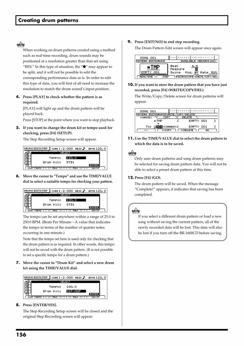
Creating drum patterns
When working on drum patterns created using a method such as real-time recording, drum sounds may be positioned at a resolution greater than that set using “RES.” In this type of situation, the “” may appear to be split, and it will not be possible to edit the corresponding performance data as is. In order to edit this type of data, you will first of all need to increase the resolution to match the drum sound’s input position.
4. Press [PLAY] to check whether the pattern is as required.
[PLAY] will light up and the drum pattern will be played back.
Press [STOP] at the point where you want to stop playback.
5. If you want to change the drum kit or tempo used for checking, press [F4] (SETUP).
The Step Recording Setup screen will appear.fig.20-016ed
6. Move the cursor to “Tempo” and use the TIME/VALUE dial to select a suitable tempo for checking your pattern.
fig.20-016fd
The tempo can be set anywhere within a range of 25.0 to 250.0 BPM. (Beats Per Minute—A value that indicates the tempo in terms of the number of quarter notes occurring in one minute.)
Note that the tempo set here is used only for checking that the drum pattern is as required. In other words, this tempo will not be saved with the drum pattern. (It is not possible to set a specific tempo for a drum pattern.)
7. Move the cursor to “Drum Kit” and select a new drum kit using the TIME/VALUE dial.
fig.20-016gd
8. Press [ENTER/YES].
The Step Recording Setup screen will be closed and the original Step Recording screen will appear.
9. Press [EXIT/NO] to end step recording.
The Drum Pattern Edit screen will appear once again.fig.20-210d
10. If you want to store the drum pattern that you have just recorded, press [F4] (WRITE/COPY/DEL).
The Write/Copy/Delete screen for drum patterns will appear.
fig.20-024d
11. Use the TIME/VALUE dial to select the drum pattern to which the data is to be saved.
Only user drum patterns and song drum patterns may be selected for saving drum pattern data. You will not be able to select a preset drum pattern at this time.
12. Press [F4] (GO).
The drum pattern will be saved. When the message “Complete!” appears, it indicates that saving has been completed.
If you select a different drum pattern or load a new song without saving the current pattern, all of the newly recorded data will be lost. This data will also be lost if you turn off the BR-1600CD before saving.
156
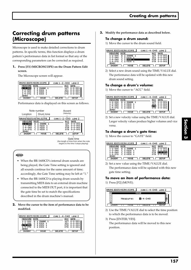
Creating drum patterns
Section 3
Correcting drum patterns (Microscope)Microscope is used to make detailed corrections to drum patterns. In specific terms, this function displays a drum pattern’s performance data in list format so that any of the corresponding parameters can be corrected as required.
1. Press [F3] (MICROSCOPE) on the Drum Pattern Edit screen.
The Microscope screen will appear.fig.20-025d
Performance data is displayed on this screen as follows.fig.20-026d_drumsevent.bmp
2. Move the cursor to the item of performance data to be modified.
fig.20-026ad
3. Modify the performance data as described below.
To change a drum sound:1) Move the cursor to the drum sound field.
fig.20-026bd
2) Select a new drum sound using the TIME/VALUE dial.The performance data will be updated with this new drum sound setting.
To change a drum’s volume:1) Move the cursor to “ACC” field.
fig.20-026cd
2) Set a new velocity value using the TIME/VALUE dial.Larger velocity values produce higher volumes and vice versa.
To change a drum’s gate time:1) Move the cursor to “GATE” field.
fig.20-026dd
2) Set a new value using the TIME/VALUE dial.The performance data will be updated with this new gate time setting.
To move an item of performance data:1) Press [F2] (MOVE).
fig.20-026ed
2) Use the TIME/VALUE dial to select the time position to which the performance data is to be moved.
3) Press [ENTER/YES].The performance data will be moved to this new position.
Location Drum toneAccent(Velocity)
Note number
Gate time(the length of time from when the note
begins to the time it stops playing)
• When the BR-1600CD’s internal drum sounds are being played, the Gate Time setting is ignored and all sounds continue for the same amount of time; accordingly, the Gate Time setting may be left at “1.”
• When the BR-1600CD is playing drum sounds by transmitting MIDI data to an external drum machine connected to the MIDI OUT port, it is important that the gate time be set to match the specifications described in the drum machine’s manual.
157
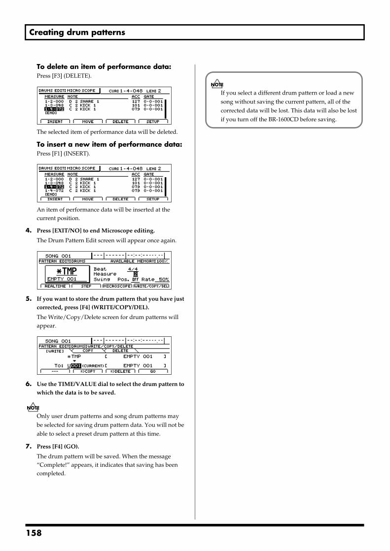
Creating drum patterns
To delete an item of performance data:Press [F3] (DELETE).
fig.20-026fd
The selected item of performance data will be deleted.
To insert a new item of performance data:Press [F1] (INSERT).
fig.20-026gd
An item of performance data will be inserted at the current position.
4. Press [EXIT/NO] to end Microscope editing.
The Drum Pattern Edit screen will appear once again.fig.20-210d
5. If you want to store the drum pattern that you have just corrected, press [F4] (WRITE/COPY/DEL).
The Write/Copy/Delete screen for drum patterns will appear.
fig.20-024d
6. Use the TIME/VALUE dial to select the drum pattern to which the data is to be saved.
Only user drum patterns and song drum patterns may be selected for saving drum pattern data. You will not be able to select a preset drum pattern at this time.
7. Press [F4] (GO).
The drum pattern will be saved. When the message “Complete!” appears, it indicates that saving has been completed.
If you select a different drum pattern or load a new song without saving the current pattern, all of the corrected data will be lost. This data will also be lost if you turn off the BR-1600CD before saving.
158
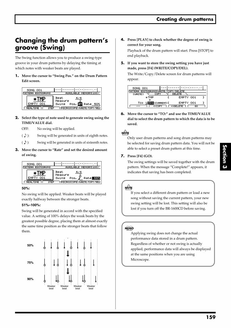
Creating drum patterns
Section 3
Changing the drum pattern’s groove (Swing)The Swing function allows you to produce a swing-type groove in your drum patterns by delaying the timing at which notes with weaker beats are played.
1. Move the cursor to “Swing Pos.” on the Drum Pattern Edit screen.
fig.20-029d
2. Select the type of note used to generate swing using the TIME/VALUE dial.
OFF: No swing will be applied.
( ): Swing will be generated in units of eighth notes.
( ): Swing will be generated in units of sixteenth notes.
3. Move the cursor to “Rate” and set the desired amount of swing.
fig.20-029ad
50%:
No swing will be applied. Weaker beats will be played exactly halfway between the stronger beats.
51%–100%:
Swing will be generated in accord with the specified value. A setting of 100% delays the weak beats by the greatest possible degree, placing them at almost exactly the same time position as the stronger beats that follow them.
fig.20-032
4. Press [PLAY] to check whether the degree of swing is correct for your song.
Playback of the drum pattern will start. Press [STOP] to end playback.
5. If you want to store the swing setting you have just made, press [F4] (WRITE/COPY/DEL).
The Write/Copy/Delete screen for drum patterns will appear.
fig.20-024d
6. Move the cursor to “TO:” and use the TIME/VALUE dial to select the drum pattern to which the data is to be saved.
Only user drum patterns and song drum patterns may be selected for saving drum pattern data. You will not be able to select a preset drum pattern at this time.
7. Press [F4] (GO).
The swing settings will be saved together with the drum pattern. When the message “Complete!” appears, it indicates that saving has been completed.
50%
75%
90%
Weakerbeat
Weakerbeat
Weakerbeat
Weakerbeat
If you select a different drum pattern or load a new song without saving the current pattern, your new swing setting will be lost. This setting will also be lost if you turn off the BR-1600CD before saving.
Applying swing does not change the actual performance data stored in a drum pattern. Regardless of whether or not swing is actually applied, performance data will always be displayed at the same positions when you are using Microscope.
159
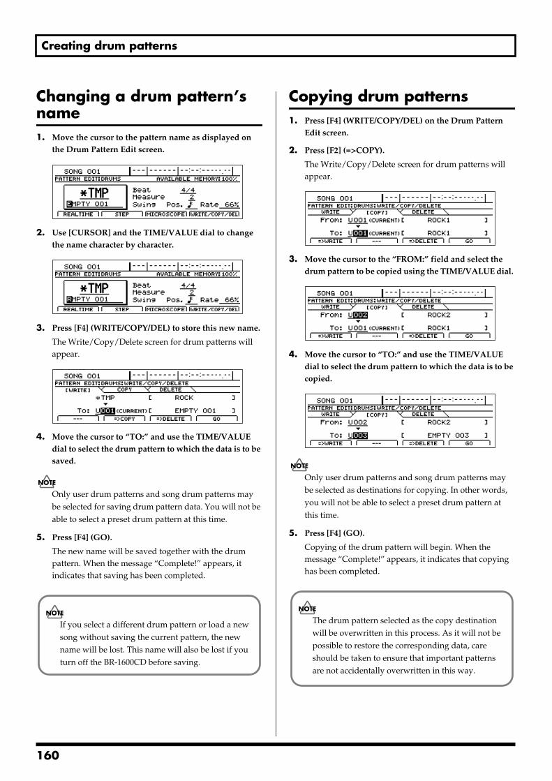
Creating drum patterns
Changing a drum pattern’s name1. Move the cursor to the pattern name as displayed on
the Drum Pattern Edit screen. fig.20-032ad
2. Use [CURSOR] and the TIME/VALUE dial to change the name character by character.
fig.20-32bd
3. Press [F4] (WRITE/COPY/DEL) to store this new name.
The Write/Copy/Delete screen for drum patterns will appear.
fig.20-124d
4. Move the cursor to “TO:” and use the TIME/VALUE dial to select the drum pattern to which the data is to be saved.
Only user drum patterns and song drum patterns may be selected for saving drum pattern data. You will not be able to select a preset drum pattern at this time.
5. Press [F4] (GO).
The new name will be saved together with the drum pattern. When the message “Complete!” appears, it indicates that saving has been completed.
Copying drum patterns1. Press [F4] (WRITE/COPY/DEL) on the Drum Pattern
Edit screen.
2. Press [F2] (=>COPY).
The Write/Copy/Delete screen for drum patterns will appear.
fig.20-224d
3. Move the cursor to the “FROM:” field and select the drum pattern to be copied using the TIME/VALUE dial.
fig.20-032cd
4. Move the cursor to “TO:” and use the TIME/VALUE dial to select the drum pattern to which the data is to be copied.
fig.20-032dd
Only user drum patterns and song drum patterns may be selected as destinations for copying. In other words, you will not be able to select a preset drum pattern at this time.
5. Press [F4] (GO).
Copying of the drum pattern will begin. When the message “Complete!” appears, it indicates that copying has been completed.
If you select a different drum pattern or load a new song without saving the current pattern, the new name will be lost. This name will also be lost if you turn off the BR-1600CD before saving.
The drum pattern selected as the copy destination will be overwritten in this process. As it will not be possible to restore the corresponding data, care should be taken to ensure that important patterns are not accidentally overwritten in this way.
160
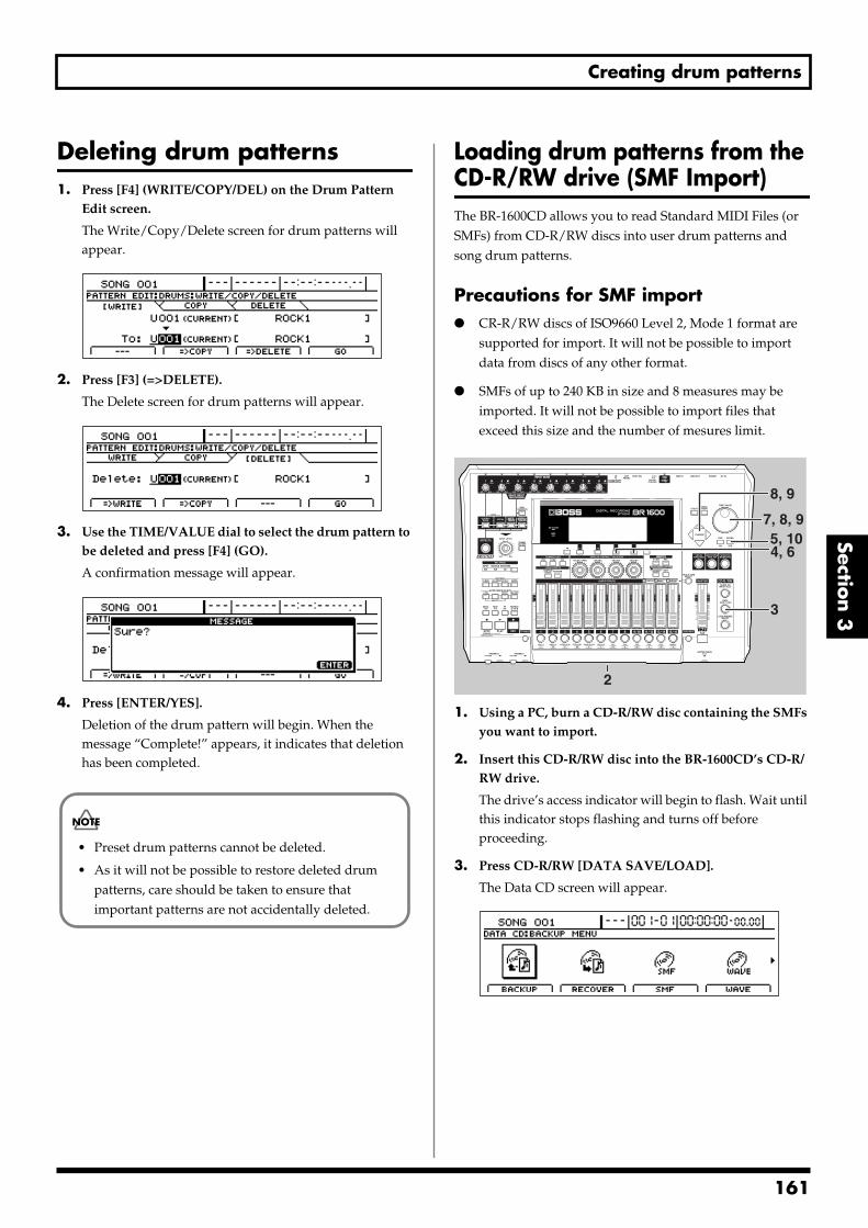
Creating drum patterns
Section 3
Deleting drum patterns1. Press [F4] (WRITE/COPY/DEL) on the Drum Pattern
Edit screen.
The Write/Copy/Delete screen for drum patterns will appear.
fig.20-324d
2. Press [F3] (=>DELETE).
The Delete screen for drum patterns will appear.fig.20-037d
3. Use the TIME/VALUE dial to select the drum pattern to be deleted and press [F4] (GO).
A confirmation message will appear.fig.20-038d
4. Press [ENTER/YES].
Deletion of the drum pattern will begin. When the message “Complete!” appears, it indicates that deletion has been completed.
Loading drum patterns from the CD-R/RW drive (SMF Import)The BR-1600CD allows you to read Standard MIDI Files (or SMFs) from CD-R/RW discs into user drum patterns and song drum patterns.
Precautions for SMF import CR-R/RW discs of ISO9660 Level 2, Mode 1 format are
supported for import. It will not be possible to import data from discs of any other format.
SMFs of up to 240 KB in size and 8 measures may be imported. It will not be possible to import files that exceed this size and the number of mesures limit.
fig.20-039
1. Using a PC, burn a CD-R/RW disc containing the SMFs you want to import.
2. Insert this CD-R/RW disc into the BR-1600CD’s CD-R/RW drive.
The drive’s access indicator will begin to flash. Wait until this indicator stops flashing and turns off before proceeding.
3. Press CD-R/RW [DATA SAVE/LOAD].
The Data CD screen will appear.fig.20-040d
• Preset drum patterns cannot be deleted.
• As it will not be possible to restore deleted drum patterns, care should be taken to ensure that important patterns are not accidentally deleted.
3
5, 104, 6
8, 9
7, 8, 9
2
161
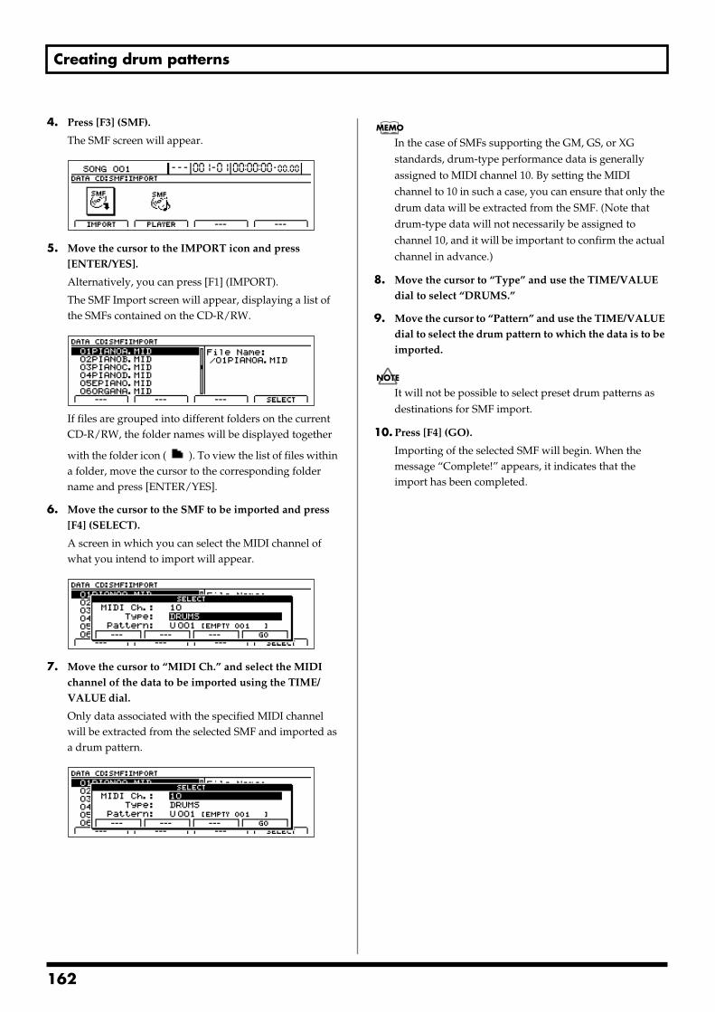
Creating drum patterns
4. Press [F3] (SMF).
The SMF screen will appear.fig.20-041d
5. Move the cursor to the IMPORT icon and press [ENTER/YES].
Alternatively, you can press [F1] (IMPORT).
The SMF Import screen will appear, displaying a list of the SMFs contained on the CD-R/RW.
fig.20-042d
If files are grouped into different folders on the current CD-R/RW, the folder names will be displayed together
with the folder icon ( ). To view the list of files within a folder, move the cursor to the corresponding folder name and press [ENTER/YES].
6. Move the cursor to the SMF to be imported and press [F4] (SELECT).
A screen in which you can select the MIDI channel of what you intend to import will appear.
fig.20-043d
7. Move the cursor to “MIDI Ch.” and select the MIDI channel of the data to be imported using the TIME/VALUE dial.
Only data associated with the specified MIDI channel will be extracted from the selected SMF and imported as a drum pattern.
fig.20-043ad
In the case of SMFs supporting the GM, GS, or XG standards, drum-type performance data is generally assigned to MIDI channel 10. By setting the MIDI channel to 10 in such a case, you can ensure that only the drum data will be extracted from the SMF. (Note that drum-type data will not necessarily be assigned to channel 10, and it will be important to confirm the actual channel in advance.)
8. Move the cursor to “Type” and use the TIME/VALUE dial to select “DRUMS.”
9. Move the cursor to “Pattern” and use the TIME/VALUE dial to select the drum pattern to which the data is to be imported.
It will not be possible to select preset drum patterns as destinations for SMF import.
10. Press [F4] (GO).
Importing of the selected SMF will begin. When the message “Complete!” appears, it indicates that the import has been completed.
162
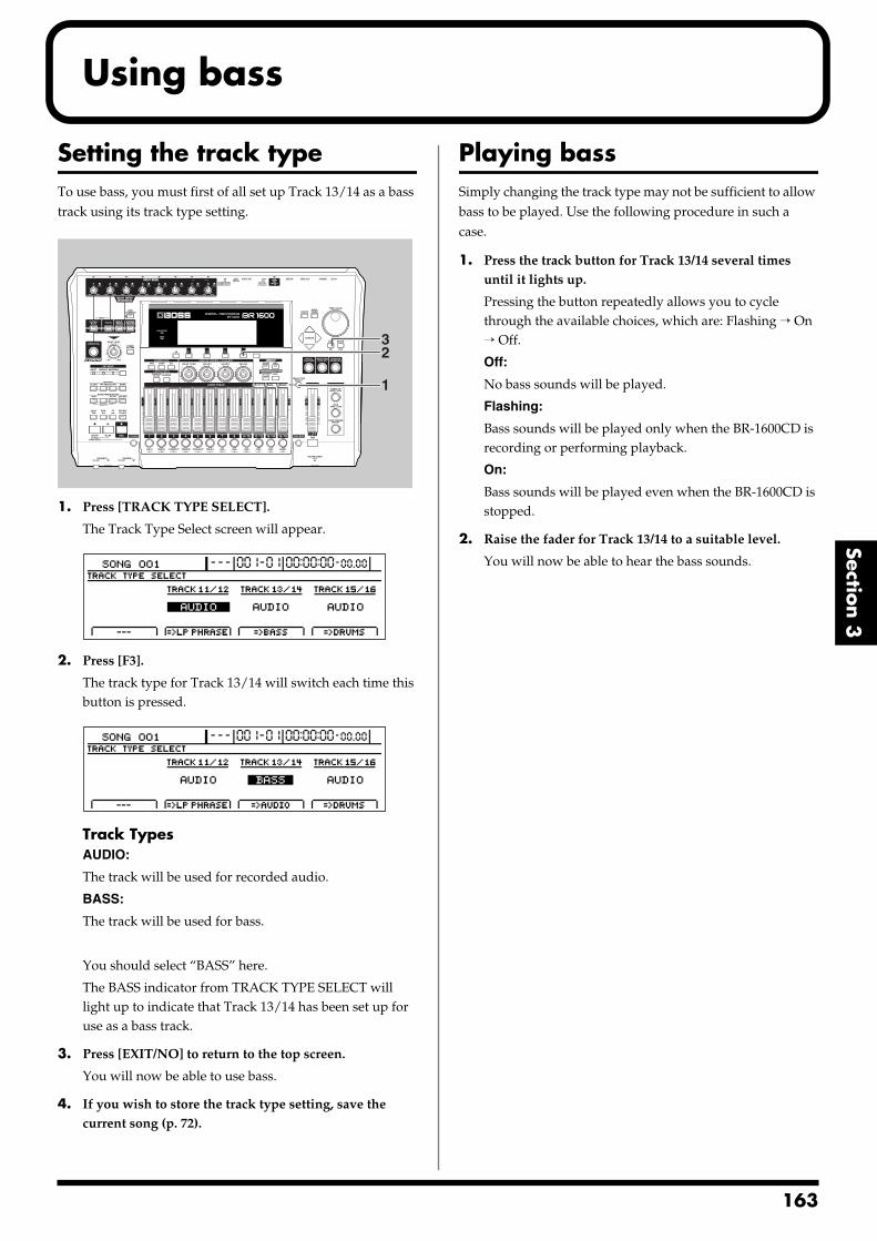
Using bass
Section 3
Setting the track typeTo use bass, you must first of all set up Track 13/14 as a bass track using its track type setting.fig.20-044
1. Press [TRACK TYPE SELECT].
The Track Type Select screen will appear.fig.20-003d
2. Press [F3].
The track type for Track 13/14 will switch each time this button is pressed.
fig.20-046d
Track TypesAUDIO:
The track will be used for recorded audio.
BASS:
The track will be used for bass.
You should select “BASS” here.
The BASS indicator from TRACK TYPE SELECT will light up to indicate that Track 13/14 has been set up for use as a bass track.
3. Press [EXIT/NO] to return to the top screen.
You will now be able to use bass.
4. If you wish to store the track type setting, save the current song (p. 72).
Playing bassSimply changing the track type may not be sufficient to allow bass to be played. Use the following procedure in such a case.
1. Press the track button for Track 13/14 several times until it lights up.
Pressing the button repeatedly allows you to cycle through the available choices, which are: Flashing → On → Off.
Off:
No bass sounds will be played.
Flashing:
Bass sounds will be played only when the BR-1600CD is recording or performing playback.
On:
Bass sounds will be played even when the BR-1600CD is stopped.
2. Raise the fader for Track 13/14 to a suitable level.
You will now be able to hear the bass sounds.
1
32
163
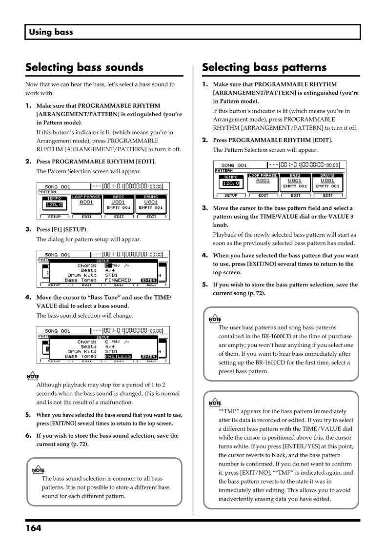
Using bass
Selecting bass soundsNow that we can hear the bass, let’s select a bass sound to work with.
1. Make sure that PROGRAMMABLE RHYTHM [ARRANGEMENT/PATTERN] is extinguished (you’re in Pattern mode).
If this button’s indicator is lit (which means you’re in Arrangement mode), press PROGRAMMABLE RHYTHM [ARRANGEMENT/PATTERN] to turn it off.
2. Press PROGRAMMABLE RHYTHM [EDIT].
The Pattern Selection screen will appear.fig.20-005d
3. Press [F1] (SETUP).
The dialog for pattern setup will appear.fig.20-006d
4. Move the cursor to “Bass Tone” and use the TIME/VALUE dial to select a bass sound.
The bass sound selection will change. fig.20-050d
Although playback may stop for a period of 1 to 2 seconds when the bass sound is changed, this is normal and is not the result of a malfunction.
5. When you have selected the bass sound that you want to use, press [EXIT/NO] several times to return to the top screen.
6. If you wish to store the bass sound selection, save the current song (p. 72).
Selecting bass patterns1. Make sure that PROGRAMMABLE RHYTHM
[ARRANGEMENT/PATTERN] is extinguished (you’re in Pattern mode).
If this button’s indicator is lit (which means you’re in Arrangement mode), press PROGRAMMABLE RHYTHM [ARRANGEMENT/PATTERN] to turn it off.
2. Press PROGRAMMABLE RHYTHM [EDIT].
The Pattern Selection screen will appear.fig.20-005d
3. Move the cursor to the bass pattern field and select a pattern using the TIME/VALUE dial or the VALUE 3 knob.
Playback of the newly selected bass pattern will start as soon as the previously selected bass pattern has ended.
4. When you have selected the bass pattern that you want to use, press [EXIT/NO] several times to return to the top screen.
5. If you wish to store the bass pattern selection, save the current song (p. 72).
The bass sound selection is common to all bass patterns. It is not possible to store a different bass sound for each different pattern.
The user bass patterns and song bass patterns contained in the BR-1600CD at the time of purchase are empty; you won’t hear anything if you select one of them. If you want to hear bass immediately after setting up the BR-1600CD for the first time, select a preset bass pattern.
“*TMP” appears for the bass pattern immediately after its data is recorded or edited. If you try to select a different bass pattern with the TIME/VALUE dial while the cursor is positioned above this, the cursor turns white. If you press [ENTER/YES] at this point, the cursor reverts to black, and the bass pattern number is confirmed. If you do not want to confirm it, press [EXIT/NO]; “*TMP” is indicated again, and the bass pattern reverts to the state it was in immediately after editing. This allows you to avoid inadvertently erasing data you have edited.
164
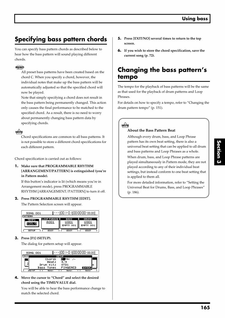
Using bass
Section 3
Specifying bass pattern chordsYou can specify bass pattern chords as described below to hear how the bass pattern will sound playing different chords.
All preset bass patterns have been created based on the chord C. When you specify a chord, however, the individual notes that make up the bass pattern will be automatically adjusted so that the specified chord will now be played.Note that simply specifying a chord does not result in the bass pattern being permanently changed. This action only causes the final performance to be matched to the specified chord. As a result, there is no need to worry about permanently changing bass pattern data by specifying chords.
Chord specifications are common to all bass patterns. It is not possible to store a different chord specifications for each different pattern.
Chord specification is carried out as follows:
1. Make sure that PROGRAMMABLE RHYTHM [ARRANGEMENT/PATTERN] is extinguished (you’re in Pattern mode).
If this button’s indicator is lit (which means you’re in Arrangement mode), press PROGRAMMABLE RHYTHM [ARRANGEMENT/PATTERN] to turn it off.
2. Press PROGRAMMABLE RHYTHM [EDIT].
The Pattern Selection screen will appear.fig.20-005d
3. Press [F1] (SETUP).
The dialog for pattern setup will appear.fig.20-006d
4. Move the cursor to “Chord” and select the desired chord using the TIME/VALUE dial.
You will be able to hear the bass performance change to match the selected chord.
5. Press [EXIT/NO] several times to return to the top screen.
6. If you wish to store the chord specification, save the current song (p. 72).
Changing the bass pattern’s tempoThe tempo for the playback of bass patterns will be the same as that used for the playback of drum patterns and Loop Phrases.
For details on how to specify a tempo, refer to “Changing the drum pattern tempo” (p. 151).
About the Bass Pattern Beat
Although every drum, bass, and Loop Phrase pattern has its own beat setting, there is also a universal beat setting that can be applied to all drum and bass patterns and Loop Phrases as a whole.
When drum, bass, and Loop Phrase patterns are played simultaneously in Pattern mode, they are not played according to any of their individual beat settings, but instead conform to one beat setting that is applied to them all.
For more detailed information, refer to “Setting the Universal Beat for Drums, Bass, and Loop Phrases” (p. 186).
165
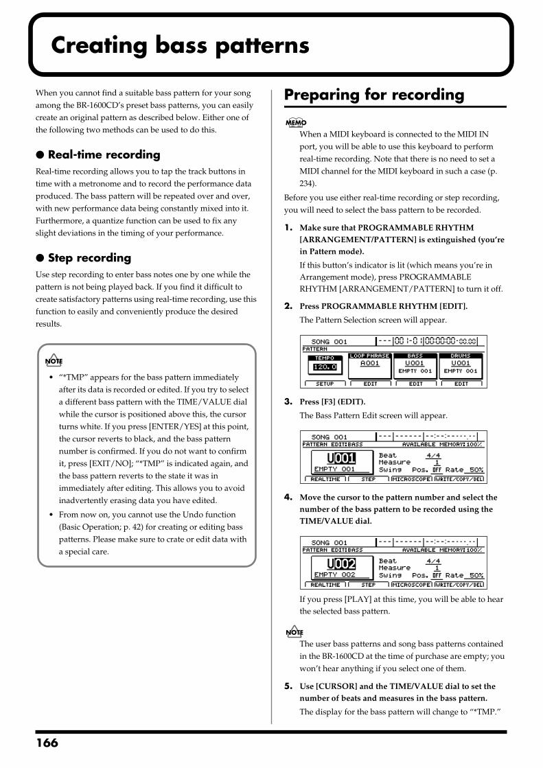
1
Creating bass patterns
When you cannot find a suitable bass pattern for your song among the BR-1600CD’s preset bass patterns, you can easily create an original pattern as described below. Either one of the following two methods can be used to do this.
Real-time recordingReal-time recording allows you to tap the track buttons in time with a metronome and to record the performance data produced. The bass pattern will be repeated over and over, with new performance data being constantly mixed into it. Furthermore, a quantize function can be used to fix any slight deviations in the timing of your performance.
Step recordingUse step recording to enter bass notes one by one while the pattern is not being played back. If you find it difficult to create satisfactory patterns using real-time recording, use this function to easily and conveniently produce the desired results.
Preparing for recording
When a MIDI keyboard is connected to the MIDI IN port, you will be able to use this keyboard to perform real-time recording. Note that there is no need to set a MIDI channel for the MIDI keyboard in such a case (p. 234).
Before you use either real-time recording or step recording, you will need to select the bass pattern to be recorded.
1. Make sure that PROGRAMMABLE RHYTHM [ARRANGEMENT/PATTERN] is extinguished (you’re in Pattern mode).
If this button’s indicator is lit (which means you’re in Arrangement mode), press PROGRAMMABLE RHYTHM [ARRANGEMENT/PATTERN] to turn it off.
2. Press PROGRAMMABLE RHYTHM [EDIT].
The Pattern Selection screen will appear.fig.20-005d
3. Press [F3] (EDIT).
The Bass Pattern Edit screen will appear.fig.20-051d
4. Move the cursor to the pattern number and select the number of the bass pattern to be recorded using the TIME/VALUE dial.
fig.20-051ad
If you press [PLAY] at this time, you will be able to hear the selected bass pattern.
The user bass patterns and song bass patterns contained in the BR-1600CD at the time of purchase are empty; you won’t hear anything if you select one of them.
5. Use [CURSOR] and the TIME/VALUE dial to set the number of beats and measures in the bass pattern.
The display for the bass pattern will change to “*TMP.”
• “*TMP” appears for the bass pattern immediately after its data is recorded or edited. If you try to select a different bass pattern with the TIME/VALUE dial while the cursor is positioned above this, the cursor turns white. If you press [ENTER/YES] at this point, the cursor reverts to black, and the bass pattern number is confirmed. If you do not want to confirm it, press [EXIT/NO]; “*TMP” is indicated again, and the bass pattern reverts to the state it was in immediately after editing. This allows you to avoid inadvertently erasing data you have edited.
• From now on, you cannot use the Undo function (Basic Operation; p. 42) for creating or editing bass patterns. Please make sure to crate or edit data with a special care.
66
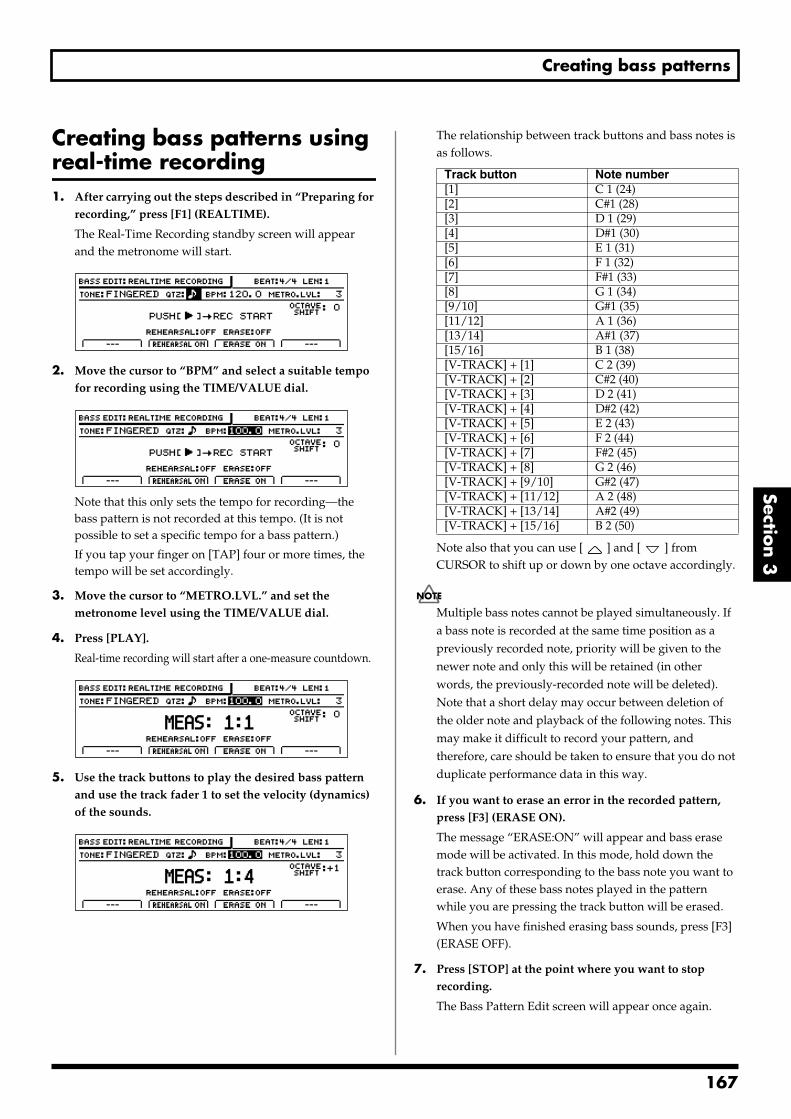
Creating bass patterns
Section 3
Creating bass patterns using real-time recording1. After carrying out the steps described in “Preparing for
recording,” press [F1] (REALTIME).
The Real-Time Recording standby screen will appear and the metronome will start.
fig.20-052d
2. Move the cursor to “BPM” and select a suitable tempo for recording using the TIME/VALUE dial.
fig.20-052ad
Note that this only sets the tempo for recording—the bass pattern is not recorded at this tempo. (It is not possible to set a specific tempo for a bass pattern.)
If you tap your finger on [TAP] four or more times, the tempo will be set accordingly.
3. Move the cursor to “METRO.LVL.” and set the metronome level using the TIME/VALUE dial.
4. Press [PLAY].
Real-time recording will start after a one-measure countdown.fig.20-053d
5. Use the track buttons to play the desired bass pattern and use the track fader 1 to set the velocity (dynamics) of the sounds.
fig.20-053a
The relationship between track buttons and bass notes is as follows.
Note also that you can use [ ] and [ ] from CURSOR to shift up or down by one octave accordingly.
Multiple bass notes cannot be played simultaneously. If a bass note is recorded at the same time position as a previously recorded note, priority will be given to the newer note and only this will be retained (in other words, the previously-recorded note will be deleted). Note that a short delay may occur between deletion of the older note and playback of the following notes. This may make it difficult to record your pattern, and therefore, care should be taken to ensure that you do not duplicate performance data in this way.
6. If you want to erase an error in the recorded pattern, press [F3] (ERASE ON).
The message “ERASE:ON” will appear and bass erase mode will be activated. In this mode, hold down the track button corresponding to the bass note you want to erase. Any of these bass notes played in the pattern while you are pressing the track button will be erased.
When you have finished erasing bass sounds, press [F3] (ERASE OFF).
7. Press [STOP] at the point where you want to stop recording.
The Bass Pattern Edit screen will appear once again.
Track button Note number[1] C 1 (24)[2] C#1 (28)[3] D 1 (29)[4] D#1 (30)[5] E 1 (31)[6] F 1 (32)[7] F#1 (33)[8] G 1 (34)[9/10] G#1 (35)[11/12] A 1 (36)[13/14] A#1 (37)[15/16] B 1 (38)[V-TRACK] + [1] C 2 (39)[V-TRACK] + [2] C#2 (40)[V-TRACK] + [3] D 2 (41)[V-TRACK] + [4] D#2 (42)[V-TRACK] + [5] E 2 (43)[V-TRACK] + [6] F 2 (44)[V-TRACK] + [7] F#2 (45)[V-TRACK] + [8] G 2 (46)[V-TRACK] + [9/10] G#2 (47)[V-TRACK] + [11/12] A 2 (48)[V-TRACK] + [13/14] A#2 (49)[V-TRACK] + [15/16] B 2 (50)
167
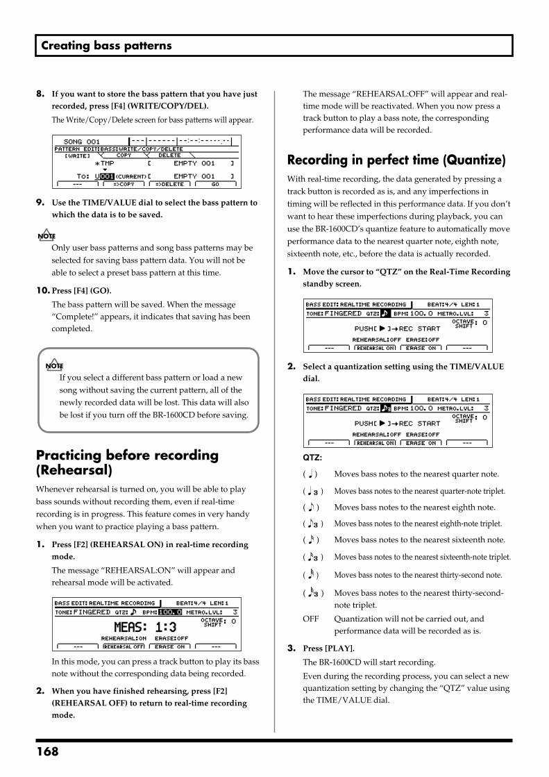
Creating bass patterns
8. If you want to store the bass pattern that you have just recorded, press [F4] (WRITE/COPY/DEL).
The Write/Copy/Delete screen for bass patterns will appear.fig.20-054d
9. Use the TIME/VALUE dial to select the bass pattern to which the data is to be saved.
Only user bass patterns and song bass patterns may be selected for saving bass pattern data. You will not be able to select a preset bass pattern at this time.
10. Press [F4] (GO).
The bass pattern will be saved. When the message “Complete!” appears, it indicates that saving has been completed.
Practicing before recording (Rehearsal)Whenever rehearsal is turned on, you will be able to play bass sounds without recording them, even if real-time recording is in progress. This feature comes in very handy when you want to practice playing a bass pattern.
1. Press [F2] (REHEARSAL ON) in real-time recording mode.
The message “REHEARSAL:ON” will appear and rehearsal mode will be activated.
fig.20-055d
In this mode, you can press a track button to play its bass note without the corresponding data being recorded.
2. When you have finished rehearsing, press [F2] (REHEARSAL OFF) to return to real-time recording mode.
The message “REHEARSAL:OFF” will appear and real-time mode will be reactivated. When you now press a track button to play a bass note, the corresponding performance data will be recorded.
Recording in perfect time (Quantize)With real-time recording, the data generated by pressing a track button is recorded as is, and any imperfections in timing will be reflected in this performance data. If you don’t want to hear these imperfections during playback, you can use the BR-1600CD’s quantize feature to automatically move performance data to the nearest quarter note, eighth note, sixteenth note, etc., before the data is actually recorded.
1. Move the cursor to “QTZ” on the Real-Time Recording standby screen.
fig.20-056d
2. Select a quantization setting using the TIME/VALUE dial.
fig.20-056a
QTZ:
( ) Moves bass notes to the nearest quarter note.
( ) Moves bass notes to the nearest quarter-note triplet.
( ) Moves bass notes to the nearest eighth note.
( ) Moves bass notes to the nearest eighth-note triplet.
( ) Moves bass notes to the nearest sixteenth note.
( ) Moves bass notes to the nearest sixteenth-note triplet.
( ) Moves bass notes to the nearest thirty-second note.
( ) Moves bass notes to the nearest thirty-second-note triplet.
OFF Quantization will not be carried out, and performance data will be recorded as is.
3. Press [PLAY].
The BR-1600CD will start recording.
Even during the recording process, you can select a new quantization setting by changing the “QTZ” value using the TIME/VALUE dial.
If you select a different bass pattern or load a new song without saving the current pattern, all of the newly recorded data will be lost. This data will also be lost if you turn off the BR-1600CD before saving.
168
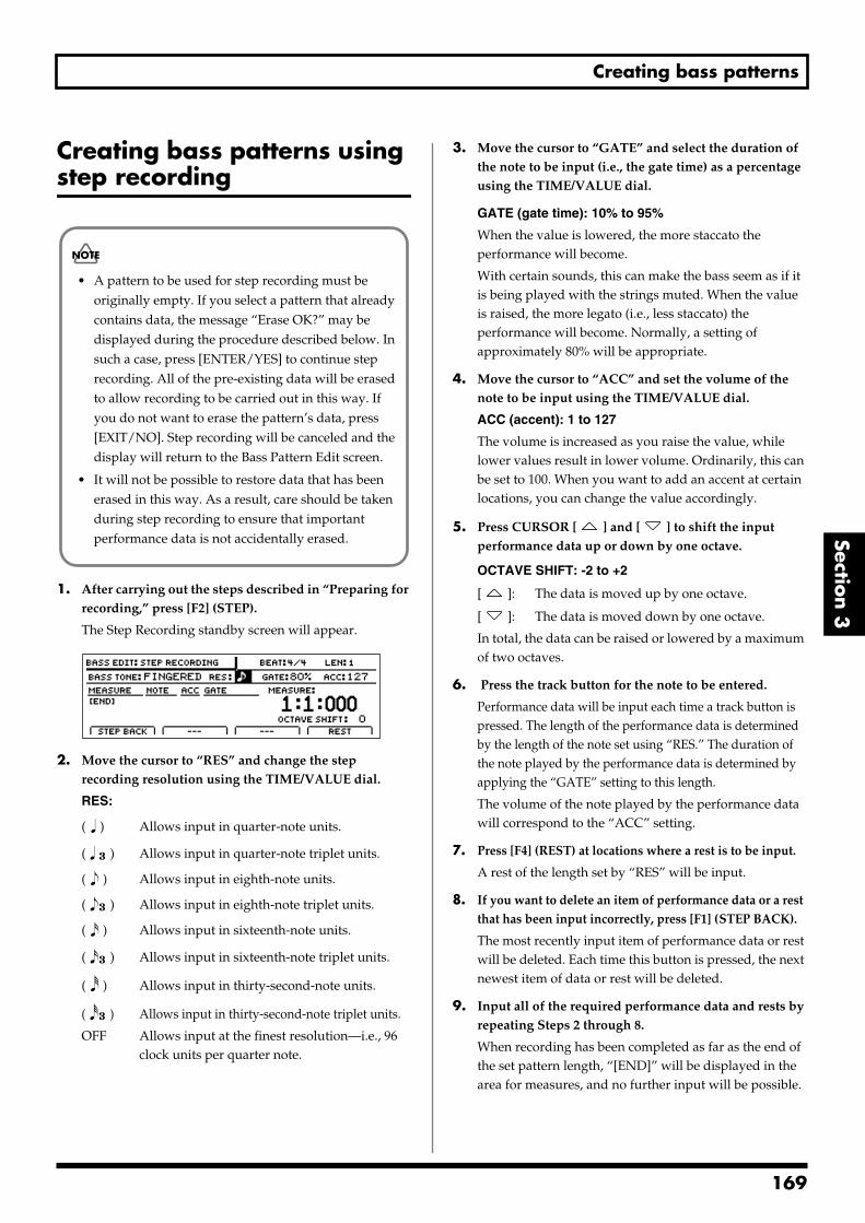
Creating bass patterns
Section 3
Creating bass patterns using step recording
1. After carrying out the steps described in “Preparing for recording,” press [F2] (STEP).
The Step Recording standby screen will appear.fig.20-065d
2. Move the cursor to “RES” and change the step recording resolution using the TIME/VALUE dial.
RES:
( ) Allows input in quarter-note units.
( ) Allows input in quarter-note triplet units.
( ) Allows input in eighth-note units.
( ) Allows input in eighth-note triplet units.
( ) Allows input in sixteenth-note units.
( ) Allows input in sixteenth-note triplet units.
( ) Allows input in thirty-second-note units.
( ) Allows input in thirty-second-note triplet units.
OFF Allows input at the finest resolution—i.e., 96 clock units per quarter note.
3. Move the cursor to “GATE” and select the duration of the note to be input (i.e., the gate time) as a percentage using the TIME/VALUE dial.
GATE (gate time): 10% to 95%
When the value is lowered, the more staccato the performance will become.
With certain sounds, this can make the bass seem as if it is being played with the strings muted. When the value is raised, the more legato (i.e., less staccato) the performance will become. Normally, a setting of approximately 80% will be appropriate.
4. Move the cursor to “ACC” and set the volume of the note to be input using the TIME/VALUE dial.
ACC (accent): 1 to 127
The volume is increased as you raise the value, while lower values result in lower volume. Ordinarily, this can be set to 100. When you want to add an accent at certain locations, you can change the value accordingly.
5. Press CURSOR [ ] and [ ] to shift the input performance data up or down by one octave.
OCTAVE SHIFT: -2 to +2
[ ]: The data is moved up by one octave.
[ ]: The data is moved down by one octave.
In total, the data can be raised or lowered by a maximum of two octaves.
6. Press the track button for the note to be entered.
Performance data will be input each time a track button is pressed. The length of the performance data is determined by the length of the note set using “RES.” The duration of the note played by the performance data is determined by applying the “GATE” setting to this length.
The volume of the note played by the performance data will correspond to the “ACC” setting.
7. Press [F4] (REST) at locations where a rest is to be input.
A rest of the length set by “RES” will be input.
8. If you want to delete an item of performance data or a rest that has been input incorrectly, press [F1] (STEP BACK).
The most recently input item of performance data or rest will be deleted. Each time this button is pressed, the next newest item of data or rest will be deleted.
9. Input all of the required performance data and rests by repeating Steps 2 through 8.
When recording has been completed as far as the end of the set pattern length, “[END]” will be displayed in the area for measures, and no further input will be possible.
• A pattern to be used for step recording must be originally empty. If you select a pattern that already contains data, the message “Erase OK?” may be displayed during the procedure described below. In such a case, press [ENTER/YES] to continue step recording. All of the pre-existing data will be erased to allow recording to be carried out in this way. If you do not want to erase the pattern’s data, press [EXIT/NO]. Step recording will be canceled and the display will return to the Bass Pattern Edit screen.
• It will not be possible to restore data that has been erased in this way. As a result, care should be taken during step recording to ensure that important performance data is not accidentally erased.
169
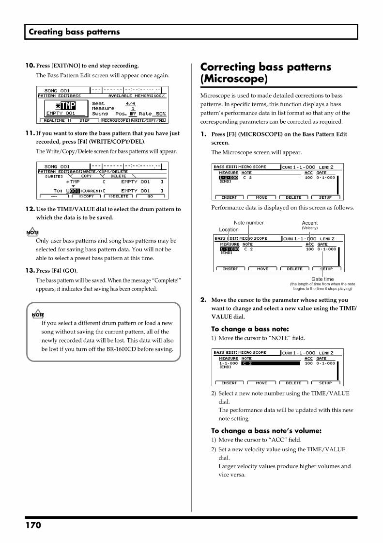
Creating bass patterns
10. Press [EXIT/NO] to end step recording.
The Bass Pattern Edit screen will appear once again.fig.20-066d
11. If you want to store the bass pattern that you have just recorded, press [F4] (WRITE/COPY/DEL).
The Write/Copy/Delete screen for bass patterns will appear.fig.20-067d
12. Use the TIME/VALUE dial to select the drum pattern to which the data is to be saved.
Only user bass patterns and song bass patterns may be selected for saving bass pattern data. You will not be able to select a preset bass pattern at this time.
13. Press [F4] (GO).
The bass pattern will be saved. When the message “Complete!” appears, it indicates that saving has been completed.
Correcting bass patterns (Microscope)Microscope is used to made detailed corrections to bass patterns. In specific terms, this function displays a bass pattern’s performance data in list format so that any of the corresponding parameters can be corrected as required.
1. Press [F3] (MICROSCOPE) on the Bass Pattern Edit screen.
The Microscope screen will appear.fig.20-068d
Performance data is displayed on this screen as follows.fig.20-069d
2. Move the cursor to the parameter whose setting you want to change and select a new value using the TIME/VALUE dial.
To change a bass note:1) Move the cursor to “NOTE” field.
fig.20-069ad
2) Select a new note number using the TIME/VALUE dial.The performance data will be updated with this new note setting.
To change a bass note’s volume:1) Move the cursor to “ACC” field.
2) Set a new velocity value using the TIME/VALUE dial.Larger velocity values produce higher volumes and vice versa.
If you select a different drum pattern or load a new song without saving the current pattern, all of the newly recorded data will be lost. This data will also be lost if you turn off the BR-1600CD before saving.
LocationAccent(Velocity)
Note number
Gate time(the length of time from when the note
begins to the time it stops playing)
170
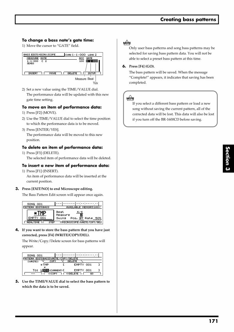
Creating bass patterns
Section 3
To change a bass note’s gate time:1) Move the cursor to “GATE” field.
fig.20-069b
2) Set a new value using the TIME/VALUE dial.The performance data will be updated with this new gate time setting.
To move an item of performance data:1) Press [F2] (MOVE).
2) Use the TIME/VALUE dial to select the time position to which the performance data is to be moved.
3) Press [ENTER/YES].The performance data will be moved to this new position.
To delete an item of performance data:1) Press [F3] (DELETE).
The selected item of performance data will be deleted.
To insert a new item of performance data:1) Press [F1] (INSERT).
An item of performance data will be inserted at the current position.
3. Press [EXIT/NO] to end Microscope editing.
The Bass Pattern Edit screen will appear once again.fig.20-151d
4. If you want to store the bass pattern that you have just corrected, press [F4] (WRITE/COPY/DEL).
The Write/Copy/Delete screen for bass patterns will appear.
fig.20-054d
5. Use the TIME/VALUE dial to select the bass pattern to which the data is to be saved.
Only user bass patterns and song bass patterns may be selected for saving bass pattern data. You will not be able to select a preset bass pattern at this time.
6. Press [F4] (GO).
The bass pattern will be saved. When the message “Complete!” appears, it indicates that saving has been completed.
Measure BeatTick
If you select a different bass pattern or load a new song without saving the current pattern, all of the corrected data will be lost. This data will also be lost if you turn off the BR-1600CD before saving.
171
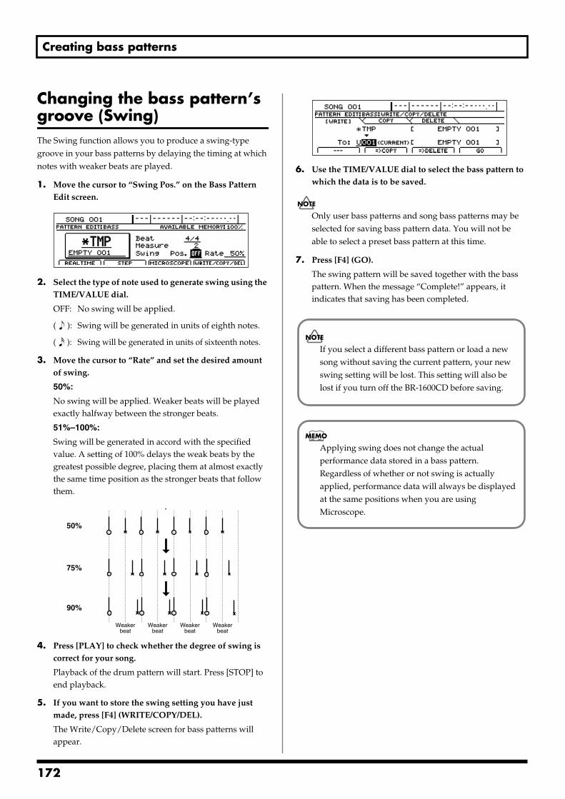
Creating bass patterns
Changing the bass pattern’s groove (Swing)The Swing function allows you to produce a swing-type groove in your bass patterns by delaying the timing at which notes with weaker beats are played.
1. Move the cursor to “Swing Pos.” on the Bass Pattern Edit screen.
fig.20-072d
2. Select the type of note used to generate swing using the TIME/VALUE dial.
OFF: No swing will be applied.
( ): Swing will be generated in units of eighth notes.
( ): Swing will be generated in units of sixteenth notes.
3. Move the cursor to “Rate” and set the desired amount of swing.
50%:
No swing will be applied. Weaker beats will be played exactly halfway between the stronger beats.
51%–100%:
Swing will be generated in accord with the specified value. A setting of 100% delays the weak beats by the greatest possible degree, placing them at almost exactly the same time position as the stronger beats that follow them.
fig.20-073
4. Press [PLAY] to check whether the degree of swing is correct for your song.
Playback of the drum pattern will start. Press [STOP] to end playback.
5. If you want to store the swing setting you have just made, press [F4] (WRITE/COPY/DEL).
The Write/Copy/Delete screen for bass patterns will appear.
fig.20-054d
6. Use the TIME/VALUE dial to select the bass pattern to which the data is to be saved.
Only user bass patterns and song bass patterns may be selected for saving bass pattern data. You will not be able to select a preset bass pattern at this time.
7. Press [F4] (GO).
The swing pattern will be saved together with the bass pattern. When the message “Complete!” appears, it indicates that saving has been completed.
50%
75%
90%
Weakerbeat
Weakerbeat
Weakerbeat
Weakerbeat
If you select a different bass pattern or load a new song without saving the current pattern, your new swing setting will be lost. This setting will also be lost if you turn off the BR-1600CD before saving.
Applying swing does not change the actual performance data stored in a bass pattern. Regardless of whether or not swing is actually applied, performance data will always be displayed at the same positions when you are using Microscope.
172
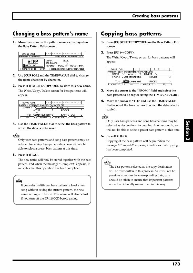
Creating bass patterns
Section 3
Changing a bass pattern’s name1. Move the cursor to the pattern name as displayed on
the Bass Pattern Edit screen. fig.20-1000d
2. Use [CURSOR] and the TIME/VALUE dial to change the name character by character.
3. Press [F4] (WRITE/COPY/DEL) to store this new name.
The Write/Copy/Delete screen for bass patterns will appear.
fig.20-154d
4. Use the TIME/VALUE dial to select the bass pattern to which the data is to be saved.
Only user bass patterns and song bass patterns may be selected for saving bass pattern data. You will not be able to select a preset bass pattern at this time.
5. Press [F4] (GO).
The new name will now be stored together with the bass pattern, and when the message “Complete!” appears, it indicates that this operation has been completed.
Copying bass patterns1. Press [F4] (WRITE/COPY/DEL) on the Bass Pattern Edit
screen.
2. Press [F2] (=>COPY).
The Write/Copy/Delete screen for bass patterns will appear.
fig.20-254d
3. Move the cursor to the “FROM:” field and select the bass pattern to be copied using the TIME/VALUE dial.
4. Move the cursor to “TO:” and use the TIME/VALUE dial to select the bass pattern to which the data is to be copied.
Only user bass patterns and song bass patterns may be selected as destinations for copying. In other words, you will not be able to select a preset bass pattern at this time.
5. Press [F4] (GO).
Copying of the bass pattern will begin. When the message “Complete!” appears, it indicates that copying has been completed.
If you select a different bass pattern or load a new song without saving the current pattern, the new name setting will be lost. This name will also be lost if you turn off the BR-1600CD before saving.
The bass pattern selected as the copy destination will be overwritten in this process. As it will not be possible to restore the corresponding data, care should be taken to ensure that important patterns are not accidentally overwritten in this way.
173
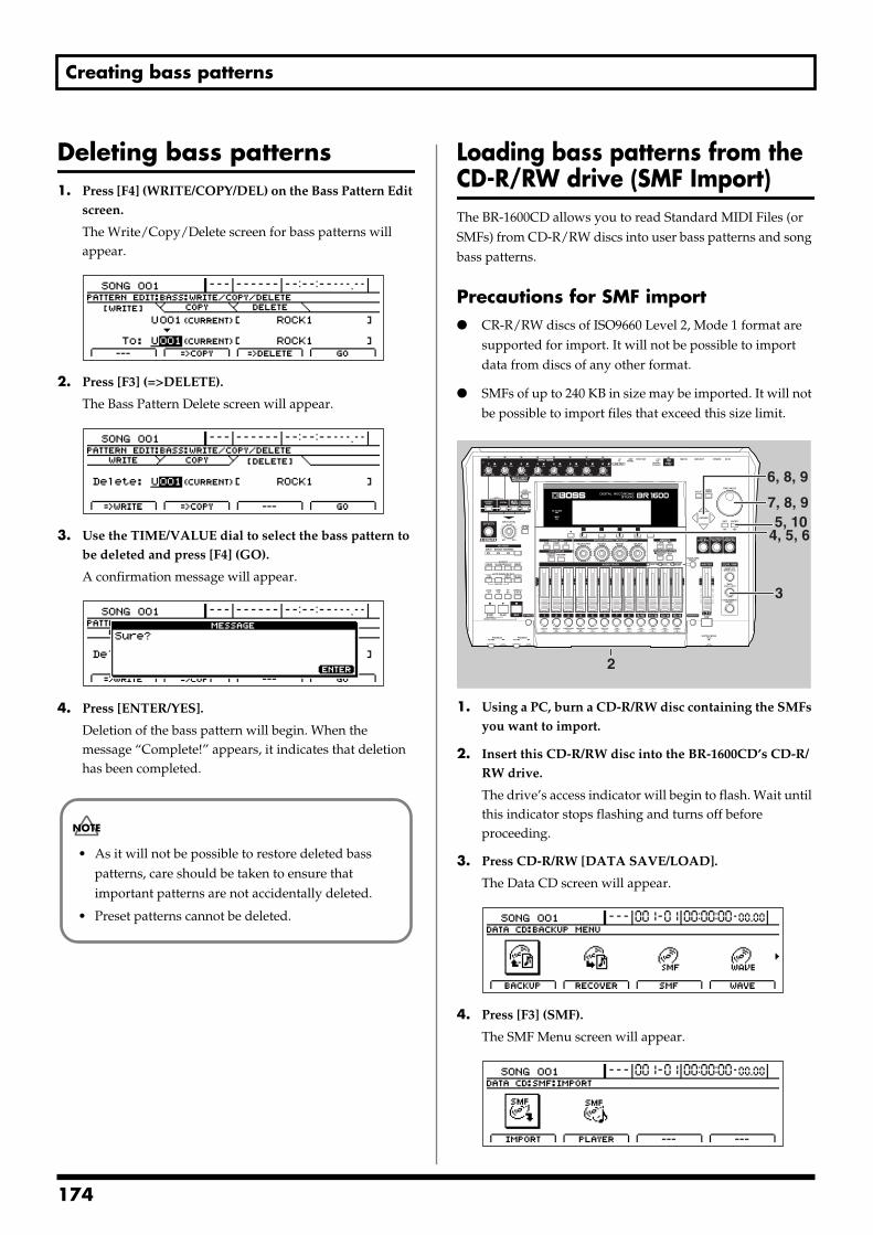
Creating bass patterns
Deleting bass patterns1. Press [F4] (WRITE/COPY/DEL) on the Bass Pattern Edit
screen.
The Write/Copy/Delete screen for bass patterns will appear.
fig.20-354dp
2. Press [F3] (=>DELETE).
The Bass Pattern Delete screen will appear.ig.20-078d_bassfrom.bmp
3. Use the TIME/VALUE dial to select the bass pattern to be deleted and press [F4] (GO).
A confirmation message will appear.fig.20-079d_bassfrom.bmp
4. Press [ENTER/YES].
Deletion of the bass pattern will begin. When the message “Complete!” appears, it indicates that deletion has been completed.
Loading bass patterns from the CD-R/RW drive (SMF Import)The BR-1600CD allows you to read Standard MIDI Files (or SMFs) from CD-R/RW discs into user bass patterns and song bass patterns.
Precautions for SMF import CR-R/RW discs of ISO9660 Level 2, Mode 1 format are
supported for import. It will not be possible to import data from discs of any other format.
SMFs of up to 240 KB in size may be imported. It will not be possible to import files that exceed this size limit.
fig.20-080
1. Using a PC, burn a CD-R/RW disc containing the SMFs you want to import.
2. Insert this CD-R/RW disc into the BR-1600CD’s CD-R/RW drive.
The drive’s access indicator will begin to flash. Wait until this indicator stops flashing and turns off before proceeding.
3. Press CD-R/RW [DATA SAVE/LOAD].
The Data CD screen will appear.fig.20-081d
4. Press [F3] (SMF).
The SMF Menu screen will appear.fig.20-082d
• As it will not be possible to restore deleted bass patterns, care should be taken to ensure that important patterns are not accidentally deleted.
• Preset patterns cannot be deleted.
3
5, 104, 5, 6
6, 8, 9
7, 8, 9
2
174
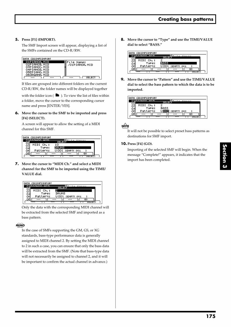
Creating bass patterns
Section 3
5. Press [F1] (IMPORT).
The SMF Import screen will appear, displaying a list of the SMFs contained on the CD-R/RW.
fig.20-083d
If files are grouped into different folders on the current CD-R/RW, the folder names will be displayed together
with the folder icon ( ). To view the list of files within a folder, move the cursor to the corresponding cursor name and press [ENTER/YES].
6. Move the cursor to the SMF to be imported and press [F4] (SELECT).
A screen will appear to allow the setting of a MIDI channel for this SMF.
fig.20-084d
7. Move the cursor to “MIDI Ch.” and select a MIDI channel for the SMF to be imported using the TIME/VALUE dial.
fig.20-084ad
Only the data with the corresponding MIDI channel will be extracted from the selected SMF and imported as a bass pattern.
In the case of SMFs supporting the GM, GS, or XG standards, bass-type performance data is generally assigned to MIDI channel 2. By setting the MIDI channel to 2 in such a case, you can ensure that only the bass data will be extracted from the SMF. (Note that bass-type data will not necessarily be assigned to channel 2, and it will be important to confirm the actual channel in advance.)
8. Move the cursor to “Type” and use the TIME/VALUE dial to select “BASS.”
fig.20-084bd
9. Move the cursor to “Pattern” and use the TIME/VALUE dial to select the bass pattern to which the data is to be imported.
fig.20-084c
It will not be possible to select preset bass patterns as destinations for SMF import.
10. Press [F4] (GO).
Importing of the selected SMF will begin. When the message “Complete!” appears, it indicates that the import has been completed.
175
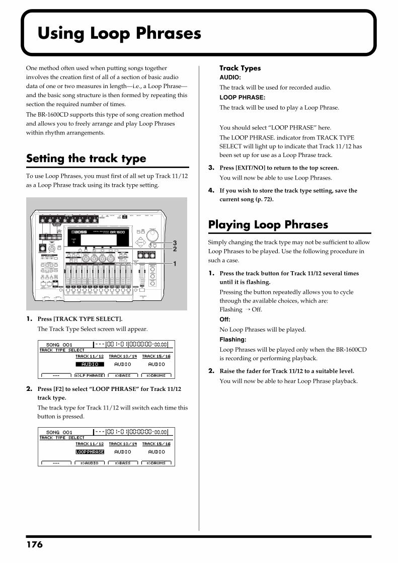
1
Using Loop Phrases
One method often used when putting songs together involves the creation first of all of a section of basic audio data of one or two measures in length—i.e., a Loop Phrase—and the basic song structure is then formed by repeating this section the required number of times.
The BR-1600CD supports this type of song creation method and allows you to freely arrange and play Loop Phrases within rhythm arrangements.
Setting the track typeTo use Loop Phrases, you must first of all set up Track 11/12 as a Loop Phrase track using its track type setting.fig.20-085
1. Press [TRACK TYPE SELECT].
The Track Type Select screen will appear.fig.20-086d
2. Press [F2] to select “LOOP PHRASE” for Track 11/12 track type.
The track type for Track 11/12 will switch each time this button is pressed.
fig.20-087d
Track TypesAUDIO:
The track will be used for recorded audio.
LOOP PHRASE:
The track will be used to play a Loop Phrase.
You should select “LOOP PHRASE” here.
The LOOP PHRASE. indicator from TRACK TYPE SELECT will light up to indicate that Track 11/12 has been set up for use as a Loop Phrase track.
3. Press [EXIT/NO] to return to the top screen.
You will now be able to use Loop Phrases.
4. If you wish to store the track type setting, save the current song (p. 72).
Playing Loop PhrasesSimply changing the track type may not be sufficient to allow Loop Phrases to be played. Use the following procedure in such a case.
1. Press the track button for Track 11/12 several times until it is flashing.
Pressing the button repeatedly allows you to cycle through the available choices, which are:Flashing → Off.
Off:
No Loop Phrases will be played.
Flashing:
Loop Phrases will be played only when the BR-1600CD is recording or performing playback.
2. Raise the fader for Track 11/12 to a suitable level.
You will now be able to hear Loop Phrase playback.
1
32
76
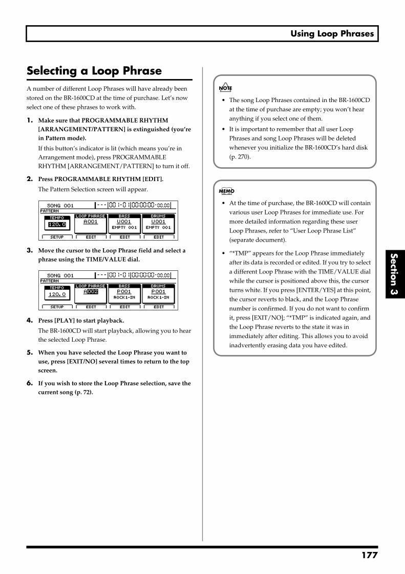
Using Loop Phrases
Section 3
Selecting a Loop PhraseA number of different Loop Phrases will have already been stored on the BR-1600CD at the time of purchase. Let’s now select one of these phrases to work with.
1. Make sure that PROGRAMMABLE RHYTHM [ARRANGEMENT/PATTERN] is extinguished (you’re in Pattern mode).
If this button’s indicator is lit (which means you’re in Arrangement mode), press PROGRAMMABLE RHYTHM [ARRANGEMENT/PATTERN] to turn it off.
2. Press PROGRAMMABLE RHYTHM [EDIT].
The Pattern Selection screen will appear.fig.20-005d
3. Move the cursor to the Loop Phrase field and select a phrase using the TIME/VALUE dial.
fig.20-087ad
4. Press [PLAY] to start playback.
The BR-1600CD will start playback, allowing you to hear the selected Loop Phrase.
5. When you have selected the Loop Phrase you want to use, press [EXIT/NO] several times to return to the top screen.
6. If you wish to store the Loop Phrase selection, save the current song (p. 72).
• The song Loop Phrases contained in the BR-1600CD at the time of purchase are empty; you won’t hear anything if you select one of them.
• It is important to remember that all user Loop Phrases and song Loop Phrases will be deleted whenever you initialize the BR-1600CD’s hard disk (p. 270).
• At the time of purchase, the BR-1600CD will contain various user Loop Phrases for immediate use. For more detailed information regarding these user Loop Phrases, refer to “User Loop Phrase List” (separate document).
• “*TMP” appears for the Loop Phrase immediately after its data is recorded or edited. If you try to select a different Loop Phrase with the TIME/VALUE dial while the cursor is positioned above this, the cursor turns white. If you press [ENTER/YES] at this point, the cursor reverts to black, and the Loop Phrase number is confirmed. If you do not want to confirm it, press [EXIT/NO]; “*TMP” is indicated again, and the Loop Phrase reverts to the state it was in immediately after editing. This allows you to avoid inadvertently erasing data you have edited.
177
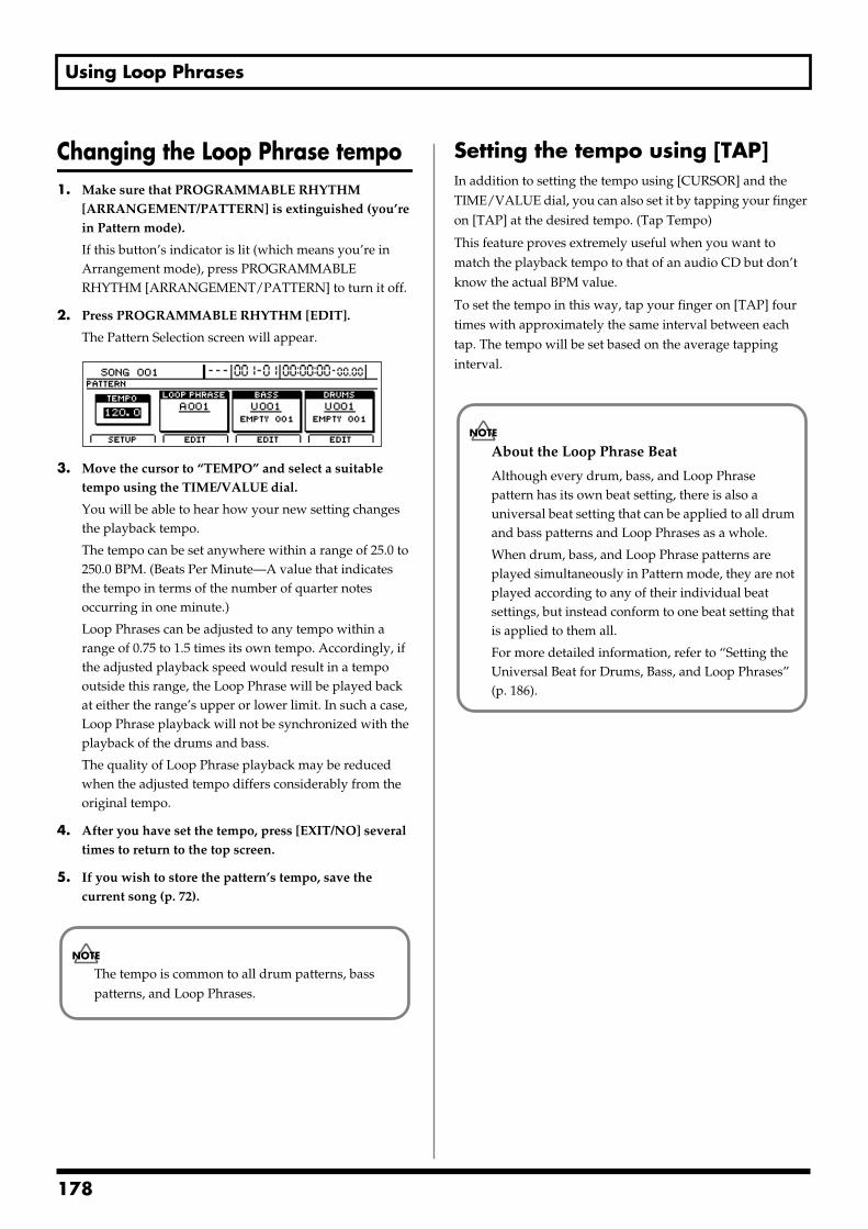
Using Loop Phrases
Changing the Loop Phrase tempo1. Make sure that PROGRAMMABLE RHYTHM
[ARRANGEMENT/PATTERN] is extinguished (you’re in Pattern mode).
If this button’s indicator is lit (which means you’re in Arrangement mode), press PROGRAMMABLE RHYTHM [ARRANGEMENT/PATTERN] to turn it off.
2. Press PROGRAMMABLE RHYTHM [EDIT].
The Pattern Selection screen will appear.fig.20-005d
3. Move the cursor to “TEMPO” and select a suitable tempo using the TIME/VALUE dial.
You will be able to hear how your new setting changes the playback tempo.
The tempo can be set anywhere within a range of 25.0 to 250.0 BPM. (Beats Per Minute—A value that indicates the tempo in terms of the number of quarter notes occurring in one minute.)
Loop Phrases can be adjusted to any tempo within a range of 0.75 to 1.5 times its own tempo. Accordingly, if the adjusted playback speed would result in a tempo outside this range, the Loop Phrase will be played back at either the range’s upper or lower limit. In such a case, Loop Phrase playback will not be synchronized with the playback of the drums and bass.
The quality of Loop Phrase playback may be reduced when the adjusted tempo differs considerably from the original tempo.
4. After you have set the tempo, press [EXIT/NO] several times to return to the top screen.
5. If you wish to store the pattern’s tempo, save the current song (p. 72).
Setting the tempo using [TAP]In addition to setting the tempo using [CURSOR] and the TIME/VALUE dial, you can also set it by tapping your finger on [TAP] at the desired tempo. (Tap Tempo)
This feature proves extremely useful when you want to match the playback tempo to that of an audio CD but don’t know the actual BPM value.
To set the tempo in this way, tap your finger on [TAP] four times with approximately the same interval between each tap. The tempo will be set based on the average tapping interval.
The tempo is common to all drum patterns, bass patterns, and Loop Phrases.
About the Loop Phrase Beat
Although every drum, bass, and Loop Phrase pattern has its own beat setting, there is also a universal beat setting that can be applied to all drum and bass patterns and Loop Phrases as a whole.
When drum, bass, and Loop Phrase patterns are played simultaneously in Pattern mode, they are not played according to any of their individual beat settings, but instead conform to one beat setting that is applied to them all.
For more detailed information, refer to “Setting the Universal Beat for Drums, Bass, and Loop Phrases” (p. 186).
178
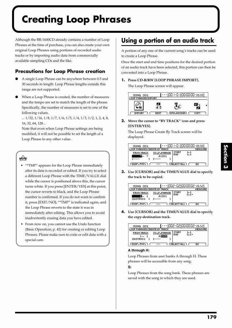
Creating Loop Phrases
Section 3
Although the BR-1600CD already contains a number of Loop Phrases at the time of purchase, you can also create your own original Loop Phrases using portions of recorded audio tracks or by importing audio data from commercially available sampling CDs and the like.
Precautions for Loop Phrase creation A single Loop Phrase can be anywhere between 0.5 and
30 seconds in length. Loop Phrase lengths outside this range are not supported.
When a Loop Phrase is created, the number of measures and the tempo are set to match the length of the phrase. Specifically, the number of measures is set to one of the following values.... 1/32, 1/16, 1/8, 1/7, 1/6, 1/5, 1/4, 1/3, 1/2, 1, 2, 4, 8, 16, 32, 64, 128...Note that even when Loop Phrase settings are being modified, it will not be possible to set the length of a Loop Phrase to any other value.
Using a portion of an audio trackA portion of any one of the current song’s tracks can be used to create a Loop Phrase.
Once the start and end time positions for the desired portion of an audio track have been selected, this portion can then be converted into a Loop Phrase.
1. Press CD-R/RW [LOOP PHRASE IMPORT].
The Loop Phrase screen will appear.fig.20-090d
2. Move the cursor to “BY TRACK” icon and press [ENTER/YES].
The Loop Phrase Create By Track screen will be displayed.
fig.20-091d
3. Use [CURSOR] and the TIME/VALUE dial to specify the track to be copied.
fig.20-091ed
4. Use [CURSOR] and the TIME/VALUE dial to specify the copy-destination track.
fig.20-091fd
A through H:
Loop Phrases from user banks A through H. These phrases will be accessible from any song.
S:
Loop Phrases from the song bank. These phrases are saved with the song in which they are used.
• “*TMP” appears for the Loop Phrase immediately after its data is recorded or edited. If you try to select a different Loop Phrase with the TIME/VALUE dial while the cursor is positioned above this, the cursor turns white. If you press [ENTER/YES] at this point, the cursor reverts to black, and the Loop Phrase number is confirmed. If you do not want to confirm it, press [EXIT/NO]; “*TMP” is indicated again, and the Loop Phrase reverts to the state it was in immediately after editing. This allows you to avoid inadvertently erasing data you have edited.
• From now on, you cannot use the Undo function (Basic Operation; p. 42) for creating or editing Loop Phrases. Please make sure to crate or edit data with a special care.
179
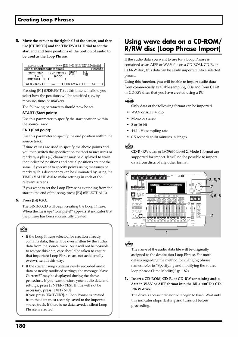
Creating Loop Phrases
5. Move the cursor to the right half of the screen, and then use [CURSOR] and the TIME/VALUE dial to set the start and end time positions of the portion of audio to be used as the Loop Phrase.
fig.20-092d
Pressing [F1] (DISP.FMT.) at this time will allow you select how the positions will be specified (i.e., by measure, time, or marker).
The following parameters should now be set.
START (Start point):
Use this parameter to specify the start position within the source track.
END (End point):
Use this parameter to specify the end position within the source track.
If time values are used to specify the above points and you then switch the specification method to measures or markers, a plus (+) character may be displayed to warn that indicated positions and actual positions are not the same. If you want to specify points using measures or markers, this discrepancy can be eliminated by using the TIME/VALUE dial to make settings in each of the relevant screens.
If you want to set the Loop Phrase as extending from the start to the end of the song, press [F3] (SELECT ALL).
6. Press [F4] (GO).
The BR-1600CD will begin creating the Loop Phrase. When the message “Complete!” appears, it indicates that the phrase has been successfully created.
Using wave data on a CD-ROM/R/RW disc (Loop Phrase Import)If the audio data you want to use for a Loop Phrase is contained as an AIFF or WAV file on a CD-ROM, CD-R, or CD-RW disc, this data can be easily imported into a selected phrase.
Using this function, you will be able to import audio data from commercially available sampling CDs and from CD-R or CD-RW discs that you have created using a PC.
Only data of the following format can be imported.
• WAV or AIFF audio
• Mono or stereo
• 8 or 16 bit
• 44.1 kHz sampling rate
• 0.5 seconds to 30 minutes in length.
CD-R/RW discs of ISO9660 Level 2, Mode 1 format are supported for import. It will not be possible to import data from discs of any other format.
fig.20-093
The name of the audio data file will be originally assigned to the destination Loop Phrase. For more details regarding the method for changing phrase names, refer to “Specifying and modifying the source loop phrase (Time Modify)” (p. 182).
1. Insert a CD-ROM, CD-R, or CD-RW containing audio data in WAV or AIFF format into the BR-1600CD’s CD-R/RW drive.
The drive’s access indicator will begin to flash. Wait until this indicator stops flashing and turns off before proceeding.
• If the Loop Phrase selected for creation already contains data, this will be overwritten by the audio data from the source track. As it will not be possible to restore this data, care should be taken to ensure that important Loop Phrases are not accidentally overwritten in this way.
• If the current song contains newly recorded audio data or newly modified settings, the message “Save Current?” may be displayed during the above procedure. If you want to store your audio data and settings, press [ENTER/YES]. If this will not be necessary, press [EXIT/NO]. If you press [EXIT/NO], a Loop Phrase is created from the data most recently saved to the imported source track. If there is no data saved, a silent Loop Phrase is created.
2
34, 6, 8
3, 5, 7
7
1
180
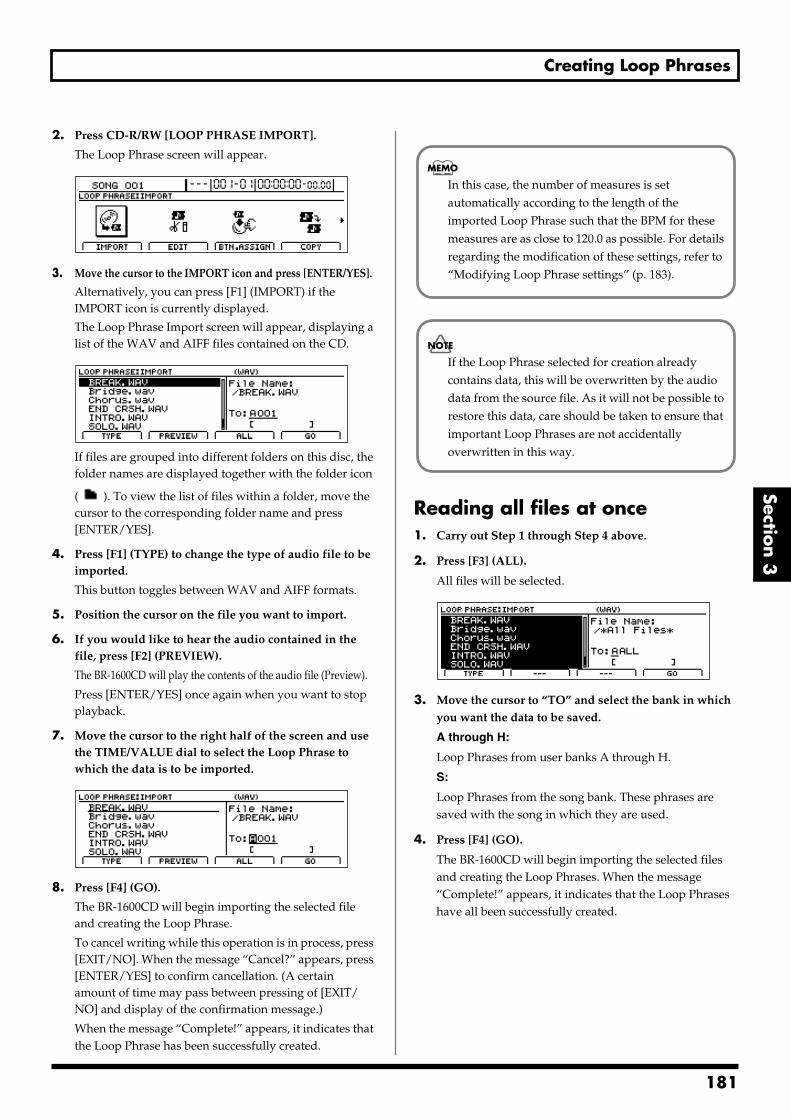
Creating Loop Phrases
Section 3
2. Press CD-R/RW [LOOP PHRASE IMPORT].
The Loop Phrase screen will appear.fig.20-090d
3. Move the cursor to the IMPORT icon and press [ENTER/YES].
Alternatively, you can press [F1] (IMPORT) if the IMPORT icon is currently displayed.
The Loop Phrase Import screen will appear, displaying a list of the WAV and AIFF files contained on the CD.
fig.20-095d
If files are grouped into different folders on this disc, the folder names are displayed together with the folder icon
( ). To view the list of files within a folder, move the cursor to the corresponding folder name and press [ENTER/YES].
4. Press [F1] (TYPE) to change the type of audio file to be imported.
This button toggles between WAV and AIFF formats.
5. Position the cursor on the file you want to import.
6. If you would like to hear the audio contained in the file, press [F2] (PREVIEW).
The BR-1600CD will play the contents of the audio file (Preview).
Press [ENTER/YES] once again when you want to stop playback.
7. Move the cursor to the right half of the screen and use the TIME/VALUE dial to select the Loop Phrase to which the data is to be imported.
fig.20-096d
8. Press [F4] (GO).
The BR-1600CD will begin importing the selected file and creating the Loop Phrase.
To cancel writing while this operation is in process, press [EXIT/NO]. When the message “Cancel?” appears, press [ENTER/YES] to confirm cancellation. (A certain amount of time may pass between pressing of [EXIT/NO] and display of the confirmation message.)
When the message “Complete!” appears, it indicates that the Loop Phrase has been successfully created.
Reading all files at once1. Carry out Step 1 through Step 4 above.
2. Press [F3] (ALL).
All files will be selected.fig.20-097d
3. Move the cursor to “TO” and select the bank in which you want the data to be saved.
A through H:
Loop Phrases from user banks A through H.
S:
Loop Phrases from the song bank. These phrases are saved with the song in which they are used.
4. Press [F4] (GO).
The BR-1600CD will begin importing the selected files and creating the Loop Phrases. When the message “Complete!” appears, it indicates that the Loop Phrases have all been successfully created.
In this case, the number of measures is set automatically according to the length of the imported Loop Phrase such that the BPM for these measures are as close to 120.0 as possible. For details regarding the modification of these settings, refer to “Modifying Loop Phrase settings” (p. 183).
If the Loop Phrase selected for creation already contains data, this will be overwritten by the audio data from the source file. As it will not be possible to restore this data, care should be taken to ensure that important Loop Phrases are not accidentally overwritten in this way.
181
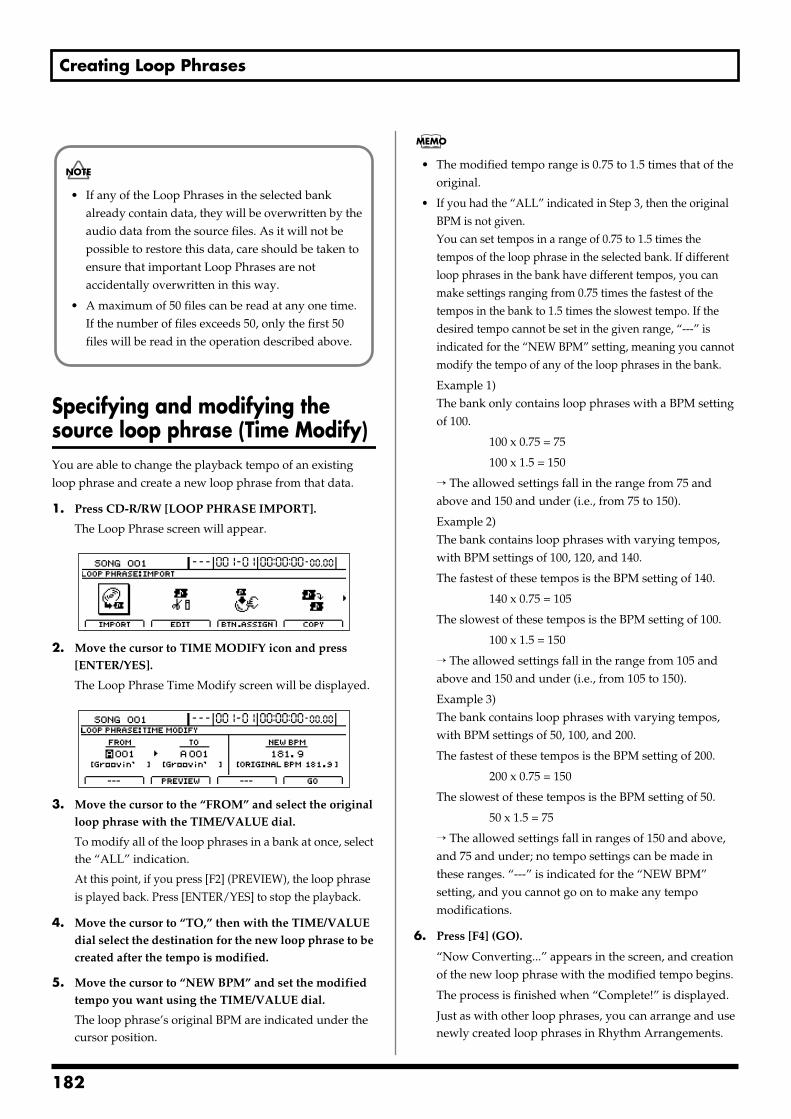
Creating Loop Phrases
Specifying and modifying the source loop phrase (Time Modify)You are able to change the playback tempo of an existing loop phrase and create a new loop phrase from that data.
1. Press CD-R/RW [LOOP PHRASE IMPORT].
The Loop Phrase screen will appear.fig.20-090d
2. Move the cursor to TIME MODIFY icon and press [ENTER/YES].
The Loop Phrase Time Modify screen will be displayed.fig.20-500d
3. Move the cursor to the “FROM” and select the original loop phrase with the TIME/VALUE dial.
To modify all of the loop phrases in a bank at once, select the “ALL” indication.
At this point, if you press [F2] (PREVIEW), the loop phrase is played back. Press [ENTER/YES] to stop the playback.
4. Move the cursor to “TO,” then with the TIME/VALUE dial select the destination for the new loop phrase to be created after the tempo is modified.
5. Move the cursor to “NEW BPM” and set the modified tempo you want using the TIME/VALUE dial.
The loop phrase’s original BPM are indicated under the cursor position.
• The modified tempo range is 0.75 to 1.5 times that of the original.
• If you had the “ALL” indicated in Step 3, then the original BPM is not given.You can set tempos in a range of 0.75 to 1.5 times the tempos of the loop phrase in the selected bank. If different loop phrases in the bank have different tempos, you can make settings ranging from 0.75 times the fastest of the tempos in the bank to 1.5 times the slowest tempo. If the desired tempo cannot be set in the given range, “---” is indicated for the “NEW BPM” setting, meaning you cannot modify the tempo of any of the loop phrases in the bank.
Example 1) The bank only contains loop phrases with a BPM setting of 100.
100 x 0.75 = 75
100 x 1.5 = 150
→ The allowed settings fall in the range from 75 and above and 150 and under (i.e., from 75 to 150).
Example 2) The bank contains loop phrases with varying tempos, with BPM settings of 100, 120, and 140.
The fastest of these tempos is the BPM setting of 140.
140 x 0.75 = 105
The slowest of these tempos is the BPM setting of 100.
100 x 1.5 = 150
→ The allowed settings fall in the range from 105 and above and 150 and under (i.e., from 105 to 150).
Example 3) The bank contains loop phrases with varying tempos, with BPM settings of 50, 100, and 200.
The fastest of these tempos is the BPM setting of 200.
200 x 0.75 = 150
The slowest of these tempos is the BPM setting of 50.
50 x 1.5 = 75
→ The allowed settings fall in ranges of 150 and above, and 75 and under; no tempo settings can be made in these ranges. “---” is indicated for the “NEW BPM” setting, and you cannot go on to make any tempo modifications.
6. Press [F4] (GO).
“Now Converting...” appears in the screen, and creation of the new loop phrase with the modified tempo begins.
The process is finished when “Complete!” is displayed.
Just as with other loop phrases, you can arrange and use newly created loop phrases in Rhythm Arrangements.
• If any of the Loop Phrases in the selected bank already contain data, they will be overwritten by the audio data from the source files. As it will not be possible to restore this data, care should be taken to ensure that important Loop Phrases are not accidentally overwritten in this way.
• A maximum of 50 files can be read at any one time. If the number of files exceeds 50, only the first 50 files will be read in the operation described above.
182
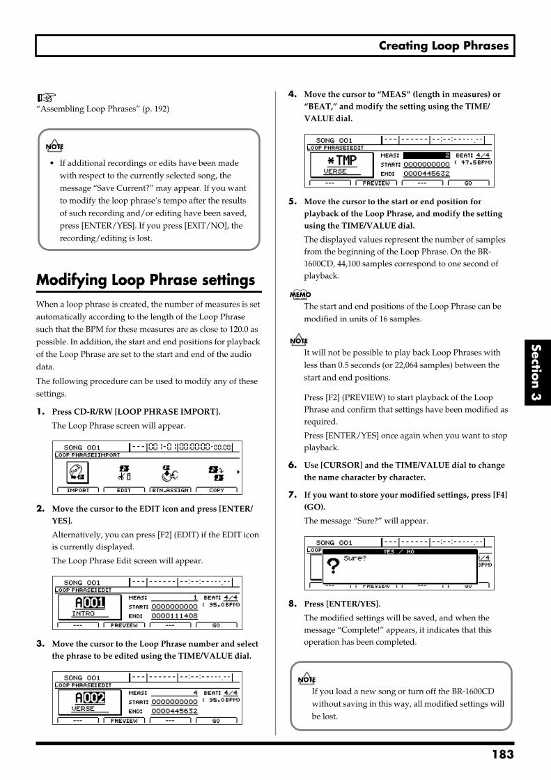
Creating Loop Phrases
Section 3
“Assembling Loop Phrases” (p. 192)
Modifying Loop Phrase settingsWhen a loop phrase is created, the number of measures is set automatically according to the length of the Loop Phrase such that the BPM for these measures are as close to 120.0 as possible. In addition, the start and end positions for playback of the Loop Phrase are set to the start and end of the audio data.
The following procedure can be used to modify any of these settings.
1. Press CD-R/RW [LOOP PHRASE IMPORT].
The Loop Phrase screen will appear.fig.20-090d
2. Move the cursor to the EDIT icon and press [ENTER/YES].
Alternatively, you can press [F2] (EDIT) if the EDIT icon is currently displayed.
The Loop Phrase Edit screen will appear.fig.20-099d
3. Move the cursor to the Loop Phrase number and select the phrase to be edited using the TIME/VALUE dial.
fig.20-100d
4. Move the cursor to “MEAS” (length in measures) or “BEAT,” and modify the setting using the TIME/VALUE dial.
fig.20-101d
5. Move the cursor to the start or end position for playback of the Loop Phrase, and modify the setting using the TIME/VALUE dial.
The displayed values represent the number of samples from the beginning of the Loop Phrase. On the BR-1600CD, 44,100 samples correspond to one second of playback.
The start and end positions of the Loop Phrase can be modified in units of 16 samples.
It will not be possible to play back Loop Phrases with less than 0.5 seconds (or 22,064 samples) between the start and end positions.
Press [F2] (PREVIEW) to start playback of the Loop Phrase and confirm that settings have been modified as required.
Press [ENTER/YES] once again when you want to stop playback.
6. Use [CURSOR] and the TIME/VALUE dial to change the name character by character.
7. If you want to store your modified settings, press [F4] (GO).
The message “Sure?” will appear.fig.20-103d
8. Press [ENTER/YES].
The modified settings will be saved, and when the message “Complete!” appears, it indicates that this operation has been completed.
• If additional recordings or edits have been made with respect to the currently selected song, the message “Save Current?” may appear. If you want to modify the loop phrase’s tempo after the results of such recording and/or editing have been saved, press [ENTER/YES]. If you press [EXIT/NO], the recording/editing is lost.
If you load a new song or turn off the BR-1600CD without saving in this way, all modified settings will be lost.
183
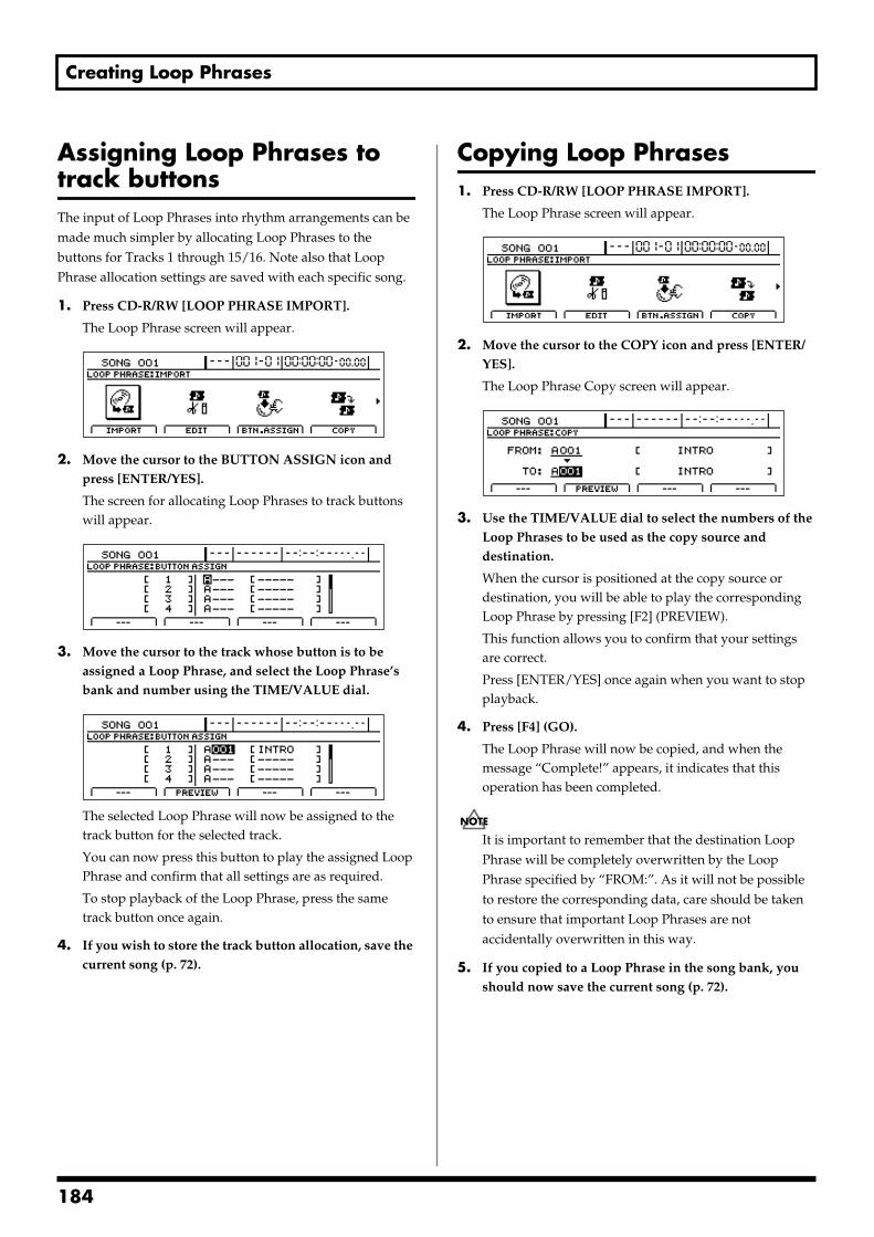
Creating Loop Phrases
Assigning Loop Phrases to track buttonsThe input of Loop Phrases into rhythm arrangements can be made much simpler by allocating Loop Phrases to the buttons for Tracks 1 through 15/16. Note also that Loop Phrase allocation settings are saved with each specific song.
1. Press CD-R/RW [LOOP PHRASE IMPORT].
The Loop Phrase screen will appear.fig.20-090d
2. Move the cursor to the BUTTON ASSIGN icon and press [ENTER/YES].
The screen for allocating Loop Phrases to track buttons will appear.
fig.20-105d
3. Move the cursor to the track whose button is to be assigned a Loop Phrase, and select the Loop Phrase’s bank and number using the TIME/VALUE dial.
fig.20-106d
The selected Loop Phrase will now be assigned to the track button for the selected track.
You can now press this button to play the assigned Loop Phrase and confirm that all settings are as required.
To stop playback of the Loop Phrase, press the same track button once again.
4. If you wish to store the track button allocation, save the current song (p. 72).
Copying Loop Phrases1. Press CD-R/RW [LOOP PHRASE IMPORT].
The Loop Phrase screen will appear.fig.20-090d
2. Move the cursor to the COPY icon and press [ENTER/YES].
The Loop Phrase Copy screen will appear.fig.20-108d
3. Use the TIME/VALUE dial to select the numbers of the Loop Phrases to be used as the copy source and destination.
When the cursor is positioned at the copy source or destination, you will be able to play the corresponding Loop Phrase by pressing [F2] (PREVIEW).
This function allows you to confirm that your settings are correct.
Press [ENTER/YES] once again when you want to stop playback.
4. Press [F4] (GO).
The Loop Phrase will now be copied, and when the message “Complete!” appears, it indicates that this operation has been completed.
It is important to remember that the destination Loop Phrase will be completely overwritten by the Loop Phrase specified by “FROM:”. As it will not be possible to restore the corresponding data, care should be taken to ensure that important Loop Phrases are not accidentally overwritten in this way.
5. If you copied to a Loop Phrase in the song bank, you should now save the current song (p. 72).
184
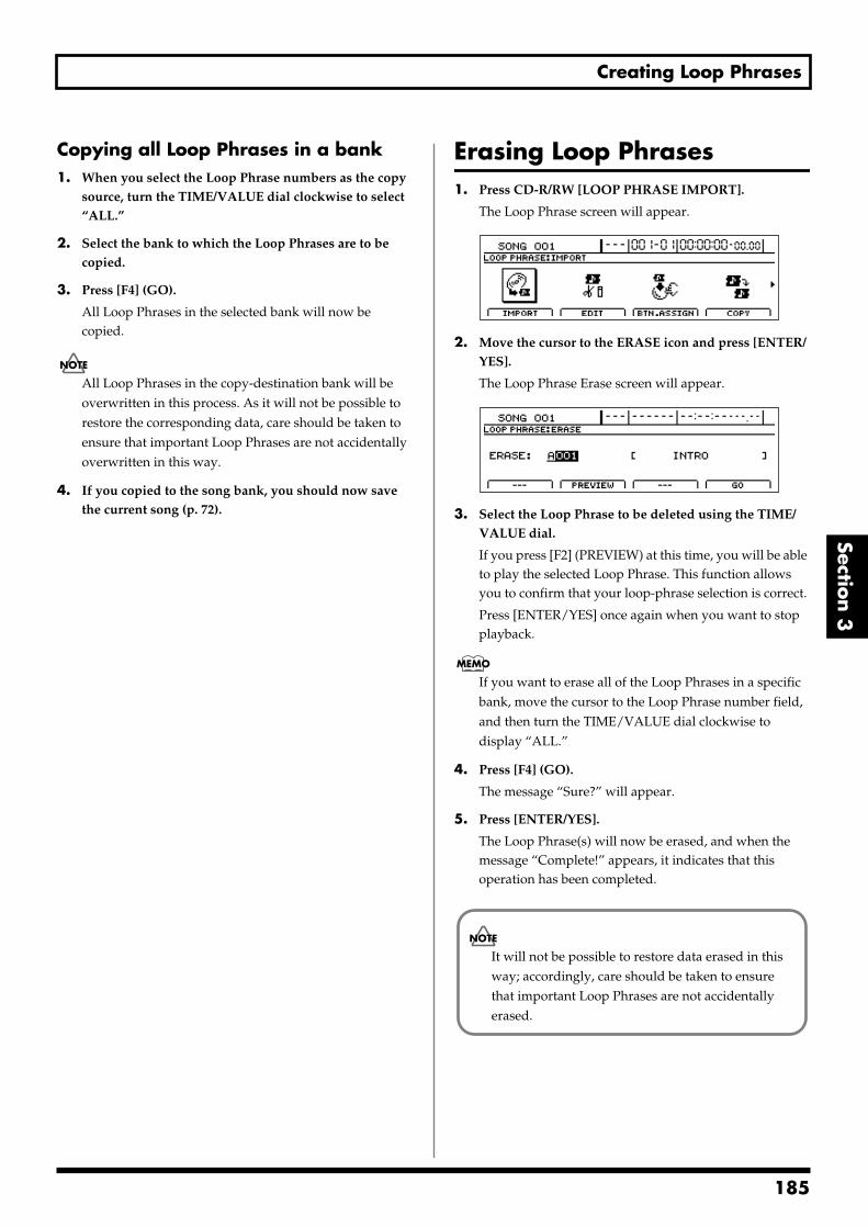
Creating Loop Phrases
Section 3
Copying all Loop Phrases in a bank1. When you select the Loop Phrase numbers as the copy
source, turn the TIME/VALUE dial clockwise to select “ALL.”
2. Select the bank to which the Loop Phrases are to be copied.
3. Press [F4] (GO).
All Loop Phrases in the selected bank will now be copied.
All Loop Phrases in the copy-destination bank will be overwritten in this process. As it will not be possible to restore the corresponding data, care should be taken to ensure that important Loop Phrases are not accidentally overwritten in this way.
4. If you copied to the song bank, you should now save the current song (p. 72).
Erasing Loop Phrases1. Press CD-R/RW [LOOP PHRASE IMPORT].
The Loop Phrase screen will appear.fig.20-090d
2. Move the cursor to the ERASE icon and press [ENTER/YES].
The Loop Phrase Erase screen will appear.fig.20-110d
3. Select the Loop Phrase to be deleted using the TIME/VALUE dial.
If you press [F2] (PREVIEW) at this time, you will be able to play the selected Loop Phrase. This function allows you to confirm that your loop-phrase selection is correct.
Press [ENTER/YES] once again when you want to stop playback.
If you want to erase all of the Loop Phrases in a specific bank, move the cursor to the Loop Phrase number field, and then turn the TIME/VALUE dial clockwise to display “ALL.”
4. Press [F4] (GO).
The message “Sure?” will appear.
5. Press [ENTER/YES].
The Loop Phrase(s) will now be erased, and when the message “Complete!” appears, it indicates that this operation has been completed.
It will not be possible to restore data erased in this way; accordingly, care should be taken to ensure that important Loop Phrases are not accidentally erased.
185
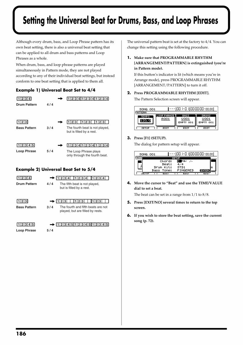
1
Setting the Universal Beat for Drums, Bass, and Loop Phrases
Although every drum, bass, and Loop Phrase pattern has its own beat setting, there is also a universal beat setting that can be applied to all drum and bass patterns and Loop Phrases as a whole.
When drum, bass, and loop phrase patterns are played simultaneously in Pattern mode, they are not played according to any of their individual beat settings, but instead conform to one beat setting that is applied to them all.
Example 1) Universal Beat Set to 4/4fig.20-200
Example 2) Universal Beat Set to 5/4fig.20-201
The universal pattern beat is set at the factory to 4/4. You can change this setting using the following procedure.
1. Make sure that PROGRAMMABLE RHYTHM [ARRANGEMENT/PATTERN] is extinguished (you’re in Pattern mode).
If this button’s indicator is lit (which means you’re in Arrange mode), press PROGRAMMABLE RHYTHM [ARRANGEMENT/PATTERN] to turn it off.
2. Press PROGRAMMABLE RHYTHM [EDIT].
The Pattern Selection screen will appear.fig.20-005d
3. Press [F1] (SETUP).
The dialog for pattern setup will appear.fig.20-006d
4. Move the cursor to “Beat” and use the TIME/VALUE dial to set a beat.
The beat can be set in a range from 1/1 to 8/8.
5. Press [EXIT/NO] several times to return to the top screen.
6. If you wish to store the beat setting, save the current song (p. 72).
2 3 41 212 3 411
2 3 4 511
2 311
2 3 41 2 3 41
2 31 2 31 2 31
2 3 41 2 3 41 2 3 41
Bass Pattern 3 / 4
Drum Pattern 4 / 4
Loop Phrase 5 / 4
The fourth beat is not played, but is filled by a rest.
The Loop Phrase plays only through the fourth beat.
2 3 411
2 3 4 511 2 3 4 511 2 3 4 511 2 3 4 511 2 3 4 511
2 311
Bass Pattern 3 / 4
Drum Pattern 4 / 4
Loop Phrase 5 / 4
The fourth and fifth beats are not played, but are filled by rests.
The fifth beat is not played, but is filled by a rest.
2 3 4 511 2 3 4 511
2 3 4 511 2 311 2 3 4 511 2 311 2 3 4 511 2 311
2 3 4 511 2 3 411 2 3 4 511 2 3 411 2 3 4 511 2 3 411
86
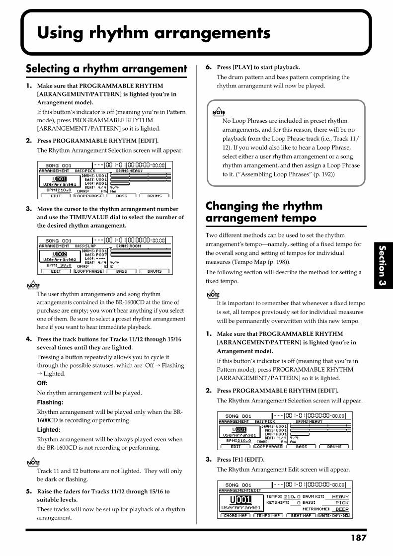
Using rhythm arrangements
Section 3
Selecting a rhythm arrangement1. Make sure that PROGRAMMABLE RHYTHM
[ARRANGEMENT/PATTERN] is lighted (you’re in Arrangement mode).
If this button’s indicator is off (meaning you’re in Pattern mode), press PROGRAMMABLE RHYTHM [ARRANGEMENT/PATTERN] so it is lighted.
2. Press PROGRAMMABLE RHYTHM [EDIT].
The Rhythm Arrangement Selection screen will appear.fig.21-33d
3. Move the cursor to the rhythm arrangement number and use the TIME/VALUE dial to select the number of the desired rhythm arrangement.
fig.21-02d
The user rhythm arrangements and song rhythm arrangements contained in the BR-1600CD at the time of purchase are empty; you won’t hear anything if you select one of them. Be sure to select a preset rhythm arrangement here if you want to hear immediate playback.
4. Press the track buttons for Tracks 11/12 through 15/16 several times until they are lighted.
Pressing a button repeatedly allows you to cycle it through the possible statuses, which are: Off → Flashing → Lighted.
Off:
No rhythm arrangement will be played.
Flashing:
Rhythm arrangement will be played only when the BR-1600CD is recording or performing.
Lighted:
Rhythm arrangement will be always played even when the BR-1600CD is not recording or performing.
Track 11 and 12 buttons are not lighted. They will only be dark or flashing.
5. Raise the faders for Tracks 11/12 through 15/16 to suitable levels.
These tracks will now be set up for playback of a rhythm arrangement.
6. Press [PLAY] to start playback.
The drum pattern and bass pattern comprising the rhythm arrangement will now be played.
Changing the rhythm arrangement tempoTwo different methods can be used to set the rhythm arrangement’s tempo—namely, setting of a fixed tempo for the overall song and setting of tempos for individual measures (Tempo Map (p. 198)).
The following section will describe the method for setting a fixed tempo.
It is important to remember that whenever a fixed tempo is set, all tempos previously set for individual measures will be permanently overwritten with this new tempo.
1. Make sure that PROGRAMMABLE RHYTHM [ARRANGEMENT/PATTERN] is lighted (you’re in Arrangement mode).
If this button’s indicator is off (meaning that you’re in Pattern mode), press PROGRAMMABLE RHYTHM [ARRANGEMENT/PATTERN] so it is lighted.
2. Press PROGRAMMABLE RHYTHM [EDIT].
The Rhythm Arrangement Selection screen will appear.fig.21-33d
3. Press [F1] (EDIT).
The Rhythm Arrangement Edit screen will appear.fig.21-04d
No Loop Phrases are included in preset rhythm arrangements, and for this reason, there will be no playback from the Loop Phrase track (i.e., Track 11/12). If you would also like to hear a Loop Phrase, select either a user rhythm arrangement or a song rhythm arrangement, and then assign a Loop Phrase to it. (“Assembling Loop Phrases” (p. 192))
187
Using rhythm arrangements
4. Move the cursor to “TEMPO” and select a suitable tempo using the TIME/VALUE dial.
You will be able to hear how your new setting changes the playback tempo.
The tempo can be set anywhere within a range of 25.0 to 250.0 BPM. (Beats Per Minute—A value that indicates the tempo in terms of the number of quarter notes occurring in one minute.)
5. After you have set the tempo, press [EXIT/NO] several times to return to the top screen.
6. If you wish to store the rhythm arrangement’s tempo, save the current rhythm arrangement (p. 195).
The tempo set for Pattern mode (p. 151, p. 165, p. 178) and the tempo set for Arrangement mode are handled separately.
Setting the tempo using [TAP]In addition to setting the tempo using [CURSOR] and the TIME/VALUE dial, you can also set it by tapping your finger on [TAP] at the desired tempo. (Tap Tempo)
This feature proves extremely useful when you want to match the playback tempo to that of an audio CD but don’t know the actual BPM value.
To set the tempo in this way, tap your finger on [TAP] four times with approximately the same interval between each tap. The tempo will be set based on the average tapping interval.
188
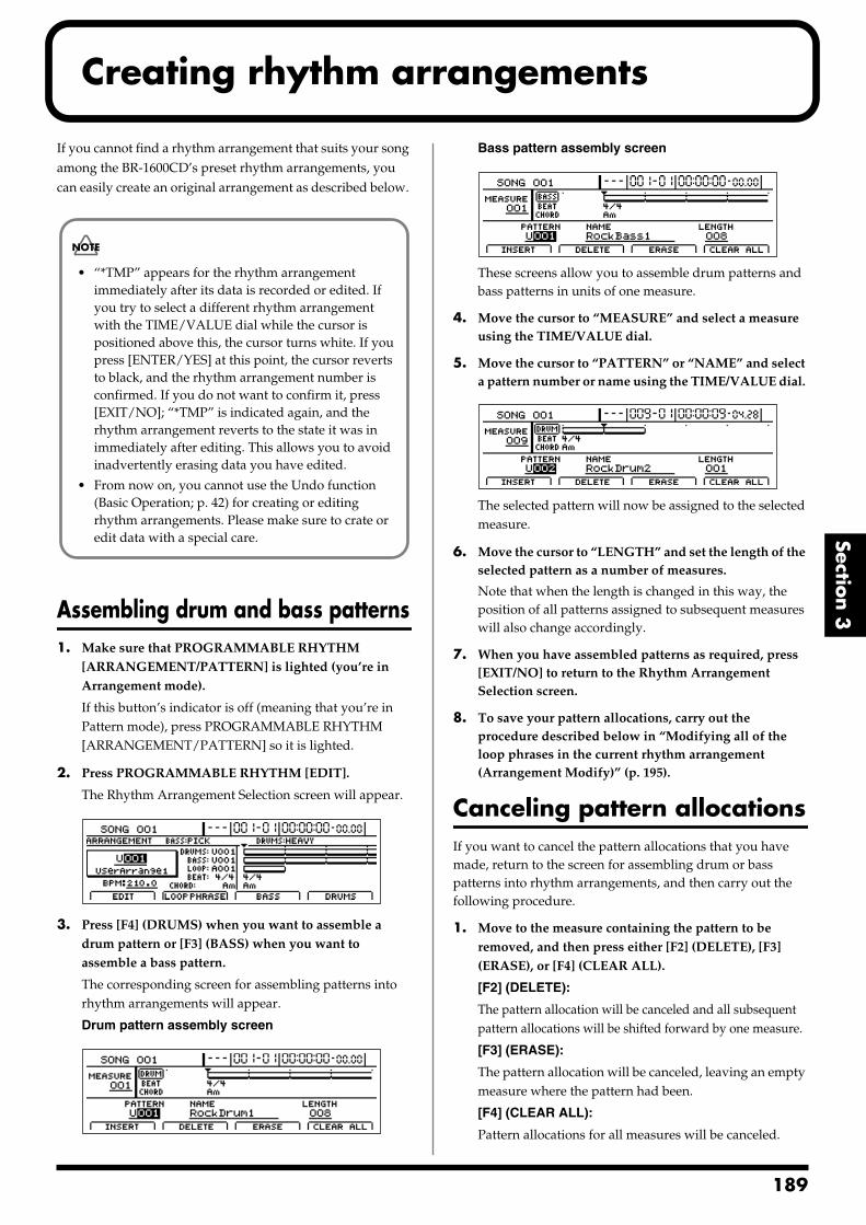
Creating rhythm arrangements
Section 3
If you cannot find a rhythm arrangement that suits your song among the BR-1600CD’s preset rhythm arrangements, you can easily create an original arrangement as described below.
Assembling drum and bass patterns1. Make sure that PROGRAMMABLE RHYTHM
[ARRANGEMENT/PATTERN] is lighted (you’re in Arrangement mode).
If this button’s indicator is off (meaning that you’re in Pattern mode), press PROGRAMMABLE RHYTHM [ARRANGEMENT/PATTERN] so it is lighted.
2. Press PROGRAMMABLE RHYTHM [EDIT].
The Rhythm Arrangement Selection screen will appear.fig.21-33d
3. Press [F4] (DRUMS) when you want to assemble a drum pattern or [F3] (BASS) when you want to assemble a bass pattern.
The corresponding screen for assembling patterns into rhythm arrangements will appear.
Drum pattern assembly screenfig.21-08d
Bass pattern assembly screenfig.21-09d
These screens allow you to assemble drum patterns and bass patterns in units of one measure.
4. Move the cursor to “MEASURE” and select a measure using the TIME/VALUE dial.
5. Move the cursor to “PATTERN” or “NAME” and select a pattern number or name using the TIME/VALUE dial.
fig.21-10ad
The selected pattern will now be assigned to the selected measure.
6. Move the cursor to “LENGTH” and set the length of the selected pattern as a number of measures.
Note that when the length is changed in this way, the position of all patterns assigned to subsequent measures will also change accordingly.
7. When you have assembled patterns as required, press [EXIT/NO] to return to the Rhythm Arrangement Selection screen.
8. To save your pattern allocations, carry out the procedure described below in “Modifying all of the loop phrases in the current rhythm arrangement (Arrangement Modify)” (p. 195).
Canceling pattern allocationsIf you want to cancel the pattern allocations that you have made, return to the screen for assembling drum or bass patterns into rhythm arrangements, and then carry out the following procedure.
1. Move to the measure containing the pattern to be removed, and then press either [F2] (DELETE), [F3] (ERASE), or [F4] (CLEAR ALL).
[F2] (DELETE):
The pattern allocation will be canceled and all subsequent pattern allocations will be shifted forward by one measure.
[F3] (ERASE):
The pattern allocation will be canceled, leaving an empty measure where the pattern had been.
[F4] (CLEAR ALL):
Pattern allocations for all measures will be canceled.
• “*TMP” appears for the rhythm arrangement immediately after its data is recorded or edited. If you try to select a different rhythm arrangement with the TIME/VALUE dial while the cursor is positioned above this, the cursor turns white. If you press [ENTER/YES] at this point, the cursor reverts to black, and the rhythm arrangement number is confirmed. If you do not want to confirm it, press [EXIT/NO]; “*TMP” is indicated again, and the rhythm arrangement reverts to the state it was in immediately after editing. This allows you to avoid inadvertently erasing data you have edited.
• From now on, you cannot use the Undo function (Basic Operation; p. 42) for creating or editing rhythm arrangements. Please make sure to crate or edit data with a special care.
189
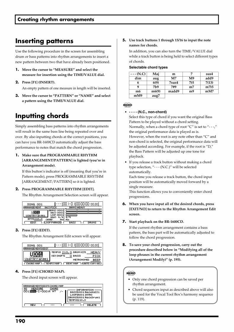
Creating rhythm arrangements
Inserting patternsUse the following procedure in the screen for assembling drum or bass patterns into rhythm arrangements to insert a new pattern between two that have already been positioned.
1. Move the cursor to “MEASURE” and select the measure for insertion using the TIME/VALUE dial.
2. Press [F1] (INSERT).
An empty pattern of one measure in length will be inserted.
3. Move the cursor to “PATTERN” or “NAME” and select a pattern using the TIME/VALUE dial.
Inputting chordsSimply assembling bass patterns into rhythm arrangements will result in the same bass line being repeated over and over. By also inputting chords at the correct positions, you can have you BR-1600CD automatically adjust the bass performance to notes that match the chord progression.
1. Make sure that PROGRAMMABLE RHYTHM [ARRANGEMENT/PATTERN] is lighted (you’re in Arrangement mode).
If this button’s indicator is off (meaning that you’re in Pattern mode), press PROGRAMMABLE RHYTHM [ARRANGEMENT/PATTERN] so it is lighted.
2. Press PROGRAMMABLE RHYTHM [EDIT].
The Rhythm Arrangement Selection screen will appear.fig.21-33d
3. Press [F1] (EDIT).
The Rhythm Arrangement Edit screen will appear.fig.21-11d_arrangeedit.bmp
4. Press [F1] (CHORD MAP).
The chord input screen will appear.fig.21-12d
5. Use track buttons 1 through 15/16 to input the note names for chords.
In addition, you can also turn the TIME/VALUE dial while a track button is being held to select different types of chords.
Selectable chord types
• - - - - (N.C., non-chord)Select this type of chord if you want the original Bass Pattern to be played without a chord setting.Normally, when a chord type of root “C” is set to “- - -,” the original performance data is played as is.However, when the root is any note other than “C” and non-chord is selected, the original performance data will be adjusted according. For example, if the root is “D,” the Bass Pattern will be adjusted up one tone for playback.
• If you release a track button without making a chord type selection, “- - - (N.C.)” will be selected automatically.Each time you release a track button, the chord input position will be automatically moved forward by a single measure.This function allows you to conveniently enter chord progressions.
6. When you have input all of the desired chords, press [EXIT/NO] to return to the Rhythm Arrangement Edit screen.
7. Start playback on the BR-1600CD.
If the current rhythm arrangement contains a bass pattern, the bass part will be automatically adjusted to follow the chord progression.
8. To save your chord progression, carry out the procedure described below in “Modifying all of the loop phrases in the current rhythm arrangement (Arrangement Modify)” (p. 195).
- - - (N.C) Maj m 7 sus4dim aug M7 M9 add9
6 6(9) 7sus4 7b5 7(13)9 7b9 7#9 m7 m7b5
m6 m6(9) madd9 m9 mM7mM9 aug7
• Only one chord progression can be saved per rhythm arrangement.
• Chord sequences input as described above will also be used for the Vocal Tool Box’s harmony sequence (p. 119).
190
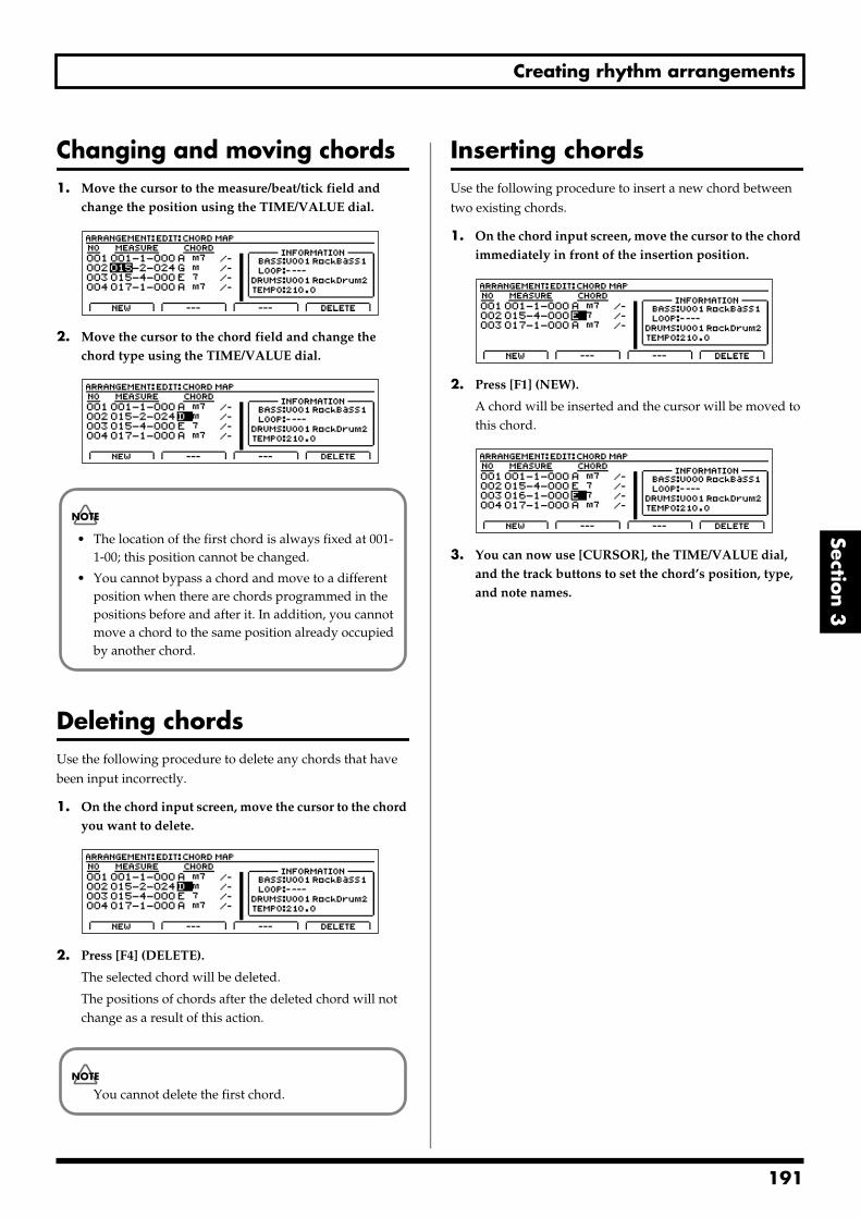
Creating rhythm arrangements
Section 3
Changing and moving chords1. Move the cursor to the measure/beat/tick field and
change the position using the TIME/VALUE dial. fig.21-13d
2. Move the cursor to the chord field and change the chord type using the TIME/VALUE dial.
fig.21-14d
Deleting chordsUse the following procedure to delete any chords that have been input incorrectly.
1. On the chord input screen, move the cursor to the chord you want to delete.
fig.21-16d
2. Press [F4] (DELETE).
The selected chord will be deleted.
The positions of chords after the deleted chord will not change as a result of this action.
Inserting chordsUse the following procedure to insert a new chord between two existing chords.
1. On the chord input screen, move the cursor to the chord immediately in front of the insertion position.
fig.21-17d
2. Press [F1] (NEW).
A chord will be inserted and the cursor will be moved to this chord.
fig.21-18d
3. You can now use [CURSOR], the TIME/VALUE dial, and the track buttons to set the chord’s position, type, and note names.
• The location of the first chord is always fixed at 001-1-00; this position cannot be changed.
• You cannot bypass a chord and move to a different position when there are chords programmed in the positions before and after it. In addition, you cannot move a chord to the same position already occupied by another chord.
You cannot delete the first chord.
191
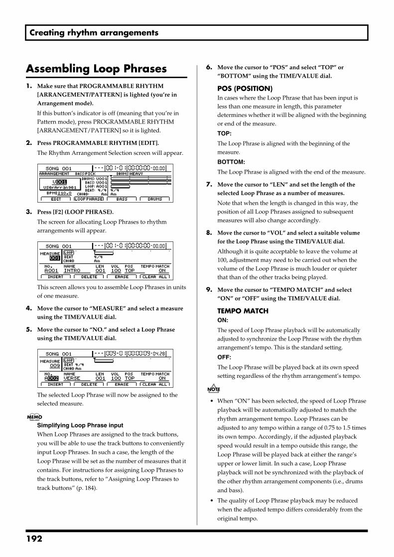
Creating rhythm arrangements
Assembling Loop Phrases1. Make sure that PROGRAMMABLE RHYTHM
[ARRANGEMENT/PATTERN] is lighted (you’re in Arrangement mode).
If this button’s indicator is off (meaning that you’re in Pattern mode), press PROGRAMMABLE RHYTHM [ARRANGEMENT/PATTERN] so it is lighted.
2. Press PROGRAMMABLE RHYTHM [EDIT].
The Rhythm Arrangement Selection screen will appear.fig.21-33d
3. Press [F2] (LOOP PHRASE).
The screen for allocating Loop Phrases to rhythm arrangements will appear.
fig.21-20d
This screen allows you to assemble Loop Phrases in units of one measure.
4. Move the cursor to “MEASURE” and select a measure using the TIME/VALUE dial.
5. Move the cursor to “NO.” and select a Loop Phrase using the TIME/VALUE dial.
fig.21-21d
The selected Loop Phrase will now be assigned to the selected measure.
Simplifying Loop Phrase input
When Loop Phrases are assigned to the track buttons, you will be able to use the track buttons to conveniently input Loop Phrases. In such a case, the length of the Loop Phrase will be set as the number of measures that it contains. For instructions for assigning Loop Phrases to the track buttons, refer to “Assigning Loop Phrases to track buttons” (p. 184).
6. Move the cursor to “POS” and select “TOP” or “BOTTOM” using the TIME/VALUE dial.
POS (POSITION)In cases where the Loop Phrase that has been input is less than one measure in length, this parameter determines whether it will be aligned with the beginning or end of the measure.
TOP:
The Loop Phrase is aligned with the beginning of the measure.
BOTTOM:
The Loop Phrase is aligned with the end of the measure.
7. Move the cursor to “LEN” and set the length of the selected Loop Phrase as a number of measures.
Note that when the length is changed in this way, the position of all Loop Phrases assigned to subsequent measures will also change accordingly.
8. Move the cursor to “VOL” and select a suitable volume for the Loop Phrase using the TIME/VALUE dial.
Although it is quite acceptable to leave the volume at 100, adjustment may need to be carried out when the volume of the Loop Phrase is much louder or quieter that than of the other tracks being played.
9. Move the cursor to “TEMPO MATCH” and select “ON” or “OFF” using the TIME/VALUE dial.
TEMPO MATCHON:
The speed of Loop Phrase playback will be automatically adjusted to synchronize the Loop Phrase with the rhythm arrangement’s tempo. This is the standard setting.
OFF:
The Loop Phrase will be played back at its own speed setting regardless of the rhythm arrangement’s tempo.
• When “ON” has been selected, the speed of Loop Phrase playback will be automatically adjusted to match the rhythm arrangement tempo. Loop Phrases can be adjusted to any tempo within a range of 0.75 to 1.5 times its own tempo. Accordingly, if the adjusted playback speed would result in a tempo outside this range, the Loop Phrase will be played back at either the range’s upper or lower limit. In such a case, Loop Phrase playback will not be synchronized with the playback of the other rhythm arrangement components (i.e., drums and bass).
• The quality of Loop Phrase playback may be reduced when the adjusted tempo differs considerably from the original tempo.
192
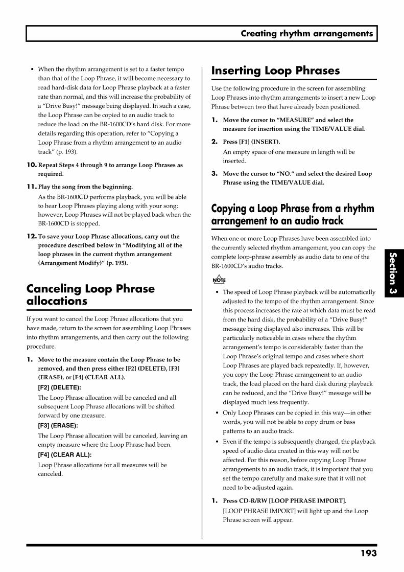
Creating rhythm arrangements
Section 3
• When the rhythm arrangement is set to a faster tempo than that of the Loop Phrase, it will become necessary to read hard-disk data for Loop Phrase playback at a faster rate than normal, and this will increase the probability of a “Drive Busy!” message being displayed. In such a case, the Loop Phrase can be copied to an audio track to reduce the load on the BR-1600CD’s hard disk. For more details regarding this operation, refer to “Copying a Loop Phrase from a rhythm arrangement to an audio track” (p. 193).
10. Repeat Steps 4 through 9 to arrange Loop Phrases as required.
11. Play the song from the beginning.
As the BR-1600CD performs playback, you will be able to hear Loop Phrases playing along with your song; however, Loop Phrases will not be played back when the BR-1600CD is stopped.
12. To save your Loop Phrase allocations, carry out the procedure described below in “Modifying all of the loop phrases in the current rhythm arrangement (Arrangement Modify)” (p. 195).
Canceling Loop Phrase allocationsIf you want to cancel the Loop Phrase allocations that you have made, return to the screen for assembling Loop Phrases into rhythm arrangements, and then carry out the following procedure.
1. Move to the measure contain the Loop Phrase to be removed, and then press either [F2] (DELETE), [F3] (ERASE), or [F4] (CLEAR ALL).
[F2] (DELETE):
The Loop Phrase allocation will be canceled and all subsequent Loop Phrase allocations will be shifted forward by one measure.
[F3] (ERASE):
The Loop Phrase allocation will be canceled, leaving an empty measure where the Loop Phrase had been.
[F4] (CLEAR ALL):
Loop Phrase allocations for all measures will be canceled.
Inserting Loop PhrasesUse the following procedure in the screen for assembling Loop Phrases into rhythm arrangements to insert a new Loop Phrase between two that have already been positioned.
1. Move the cursor to “MEASURE” and select the measure for insertion using the TIME/VALUE dial.
2. Press [F1] (INSERT).
An empty space of one measure in length will be inserted.
3. Move the cursor to “NO.” and select the desired Loop Phrase using the TIME/VALUE dial.
Copying a Loop Phrase from a rhythm arrangement to an audio trackWhen one or more Loop Phrases have been assembled into the currently selected rhythm arrangement, you can copy the complete loop-phrase assembly as audio data to one of the BR-1600CD’s audio tracks.
• The speed of Loop Phrase playback will be automatically adjusted to the tempo of the rhythm arrangement. Since this process increases the rate at which data must be read from the hard disk, the probability of a “Drive Busy!” message being displayed also increases. This will be particularly noticeable in cases where the rhythm arrangement’s tempo is considerably faster than the Loop Phrase’s original tempo and cases where short Loop Phrases are played back repeatedly. If, however, you copy the Loop Phrase arrangement to an audio track, the load placed on the hard disk during playback can be reduced, and the “Drive Busy!” message will be displayed much less frequently.
• Only Loop Phrases can be copied in this way—in other words, you will not be able to copy drum or bass patterns to an audio track.
• Even if the tempo is subsequently changed, the playback speed of audio data created in this way will not be affected. For this reason, before copying Loop Phrase arrangements to an audio track, it is important that you set the tempo carefully and make sure that it will not need to be adjusted again.
1. Press CD-R/RW [LOOP PHRASE IMPORT].
[LOOP PHRASE IMPORT] will light up and the Loop Phrase screen will appear.
193
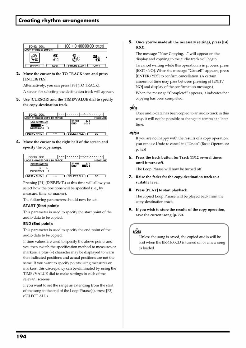
Creating rhythm arrangements
fig.21-090d
2. Move the cursor to the TO TRACK icon and press [ENTER/YES].
Alternatively, you can press [F3] (TO TRACK).
A screen for selecting the destination track will appear.
3. Use [CURSOR] and the TIME/VALUE dial to specify the copy-destination track.
fig.21-23d
4. Move the cursor to the right half of the screen and specify the copy range.
fig.21-24d
Pressing [F1] (DISP.FMT.) at this time will allow you select how the positions will be specified (i.e., by measure, time, or marker).
The following parameters should now be set.
START (Start point):
This parameter is used to specify the start point of the audio data to be copied.
END (End point):
This parameter is used to specify the end point of the audio data to be copied.
If time values are used to specify the above points and you then switch the specification method to measures or markers, a plus (+) character may be displayed to warn that indicated positions and actual positions are not the same. If you want to specify points using measures or markers, this discrepancy can be eliminated by using the TIME/VALUE dial to make settings in each of the relevant screens.
If you want to set the range as extending from the start of the song to the end of the Loop Phrase(s), press [F3] (SELECT ALL).
5. Once you’ve made all the necessary settings, press [F4] (GO).
The message “Now Copying…” will appear on the display and copying to the audio track will begin.
To cancel writing while this operation is in process, press [EXIT/NO]. When the message “Cancel?” appears, press [ENTER/YES] to confirm cancellation. (A certain amount of time may pass between pressing of [EXIT/NO] and display of the confirmation message.)
When the message “Complete!” appears, it indicates that copying has been completed.
Once audio data has been copied to an audio track in this way, it will not be possible to change its tempo at a later time.
If you are not happy with the results of a copy operation, you can use Undo to cancel it. (“Undo” (Basic Operation; p. 42))
6. Press the track button for Track 11/12 several times until it turns off.
The Loop Phrase will now be turned off.
7. Raise the fader for the copy-destination track to a suitable level.
8. Press [PLAY] to start playback.
The copied Loop Phrase will be played back from the copy-destination track.
9. If you wish to store the results of the copy operation, save the current song (p. 72).
Unless the song is saved, the copied audio will be lost when the BR-1600CD is turned off or a new song is loaded.
194
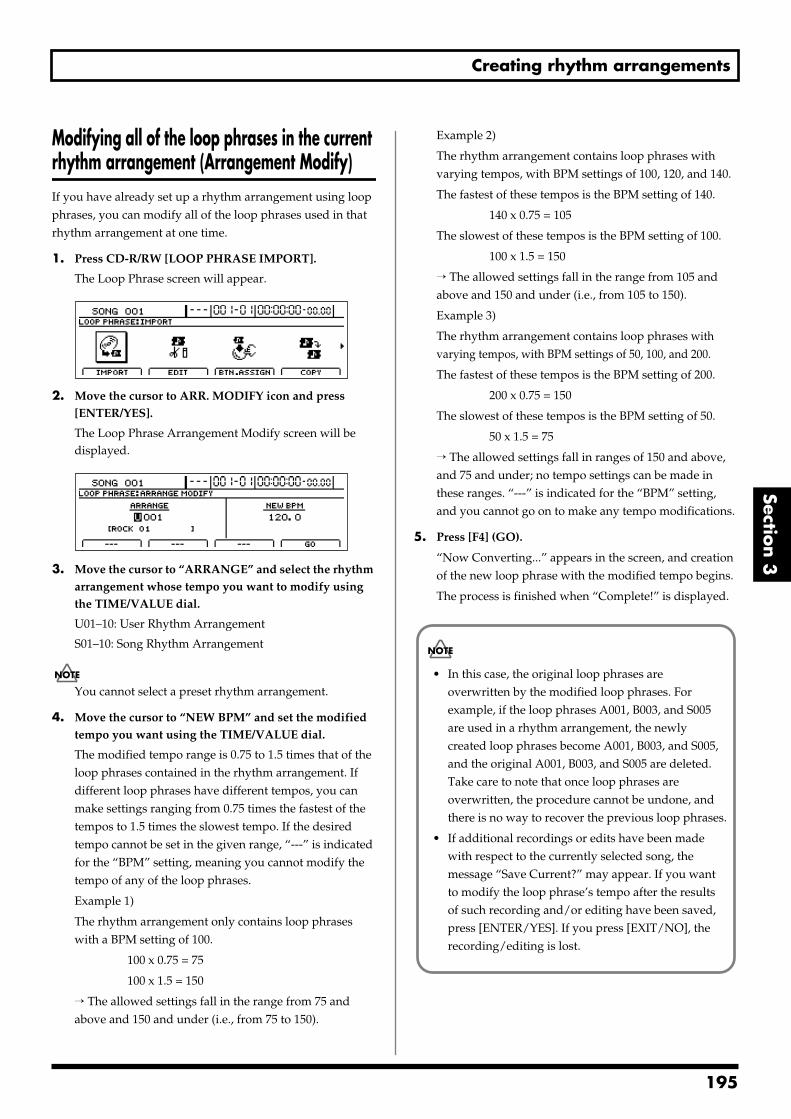
Creating rhythm arrangements
Section 3
Modifying all of the loop phrases in the current rhythm arrangement (Arrangement Modify)If you have already set up a rhythm arrangement using loop phrases, you can modify all of the loop phrases used in that rhythm arrangement at one time.
1. Press CD-R/RW [LOOP PHRASE IMPORT].
The Loop Phrase screen will appear.fig.20-090d
2. Move the cursor to ARR. MODIFY icon and press [ENTER/YES].
The Loop Phrase Arrangement Modify screen will be displayed.
fig.21-500d
3. Move the cursor to “ARRANGE” and select the rhythm arrangement whose tempo you want to modify using the TIME/VALUE dial.
U01–10: User Rhythm Arrangement
S01–10: Song Rhythm Arrangement
You cannot select a preset rhythm arrangement.
4. Move the cursor to “NEW BPM” and set the modified tempo you want using the TIME/VALUE dial.
The modified tempo range is 0.75 to 1.5 times that of the loop phrases contained in the rhythm arrangement. If different loop phrases have different tempos, you can make settings ranging from 0.75 times the fastest of the tempos to 1.5 times the slowest tempo. If the desired tempo cannot be set in the given range, “---” is indicated for the “BPM” setting, meaning you cannot modify the tempo of any of the loop phrases.
Example 1)
The rhythm arrangement only contains loop phrases with a BPM setting of 100.
100 x 0.75 = 75
100 x 1.5 = 150
→ The allowed settings fall in the range from 75 and above and 150 and under (i.e., from 75 to 150).
Example 2)
The rhythm arrangement contains loop phrases with varying tempos, with BPM settings of 100, 120, and 140.
The fastest of these tempos is the BPM setting of 140.
140 x 0.75 = 105
The slowest of these tempos is the BPM setting of 100.
100 x 1.5 = 150
→ The allowed settings fall in the range from 105 and above and 150 and under (i.e., from 105 to 150).
Example 3)
The rhythm arrangement contains loop phrases with varying tempos, with BPM settings of 50, 100, and 200.
The fastest of these tempos is the BPM setting of 200.
200 x 0.75 = 150
The slowest of these tempos is the BPM setting of 50.
50 x 1.5 = 75
→ The allowed settings fall in ranges of 150 and above, and 75 and under; no tempo settings can be made in these ranges. “---” is indicated for the “BPM” setting, and you cannot go on to make any tempo modifications.
5. Press [F4] (GO).
“Now Converting...” appears in the screen, and creation of the new loop phrase with the modified tempo begins.
The process is finished when “Complete!” is displayed.
• In this case, the original loop phrases are overwritten by the modified loop phrases. For example, if the loop phrases A001, B003, and S005 are used in a rhythm arrangement, the newly created loop phrases become A001, B003, and S005, and the original A001, B003, and S005 are deleted. Take care to note that once loop phrases are overwritten, the procedure cannot be undone, and there is no way to recover the previous loop phrases.
• If additional recordings or edits have been made with respect to the currently selected song, the message “Save Current?” may appear. If you want to modify the loop phrase’s tempo after the results of such recording and/or editing have been saved, press [ENTER/YES]. If you press [EXIT/NO], the recording/editing is lost.
195
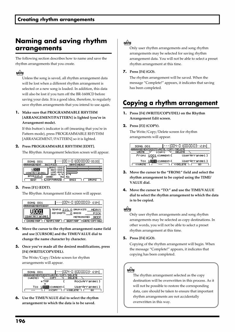
Creating rhythm arrangements
Naming and saving rhythm arrangementsThe following section describes how to name and save the rhythm arrangements that you create.
Unless the song is saved, all rhythm arrangement data will be lost when a different rhythm arrangement is selected or a new song is loaded. In addition, this data will also be lost if you turn off the BR-1600CD before saving your data. It is a good idea, therefore, to regularly save rhythm arrangements that you intend to use again.
1. Make sure that PROGRAMMABLE RHYTHM [ARRANGEMENT/PATTERN] is lighted (you’re in Arrangement mode).
If this button’s indicator is off (meaning that you’re in Pattern mode), press PROGRAMMABLE RHYTHM [ARRANGEMENT/PATTERN] so it is lighted.
2. Press PROGRAMMABLE RHYTHM [EDIT].
The Rhythm Arrangement Selection screen will appear.fig.21-33d
3. Press [F1] (EDIT).
The Rhythm Arrangement Edit screen will appear.fig.21-26d
4. Move the cursor to the rhythm arrangement name field and use [CURSOR] and the TIME/VALUE dial to change the name character by character.
5. Once you’ve made all the desired modifications, press [F4] (WRITE/COPY/DEL).
The Write/Copy/Delete screen for rhythm arrangements will appear.
fig.21-28d
6. Use the TIME/VALUE dial to select the rhythm arrangement to which the data is to be saved.
Only user rhythm arrangements and song rhythm arrangements may be selected for saving rhythm arrangement data. You will not be able to select a preset rhythm arrangement at this time.
7. Press [F4] (GO).
The rhythm arrangement will be saved. When the message “Complete!” appears, it indicates that saving has been completed.
Copying a rhythm arrangement1. Press [F4] (WRITE/COPY/DEL) on the Rhythm
Arrangement Edit screen.
2. Press [F2] (COPY).
The Write/Copy/Delete screen for rhythm arrangements will appear.
fig.21-29d
3. Move the cursor to the “FROM:” field and select the rhythm arrangement to be copied using the TIME/VALUE dial.
4. Move the cursor to “TO:” and use the TIME/VALUE dial to select the rhythm arrangement to which the data is to be copied.
Only user rhythm arrangements and song rhythm arrangements may be selected as copy destinations. In other words, you will not be able to select a preset rhythm arrangement at this time.
5. Press [F4] (GO).
Copying of the rhythm arrangement will begin. When the message “Complete!” appears, it indicates that copying has been completed.
The rhythm arrangement selected as the copy destination will be overwritten in this process. As it will not be possible to restore the corresponding data, care should be taken to ensure that important rhythm arrangements are not accidentally overwritten in this way.
196
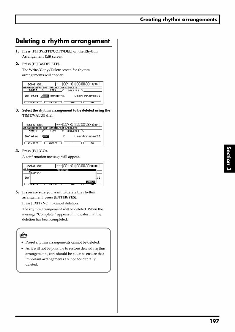
Creating rhythm arrangements
Section 3
Deleting a rhythm arrangement1. Press [F4] (WRITE/COPY/DEL) on the Rhythm
Arrangement Edit screen.
2. Press [F3] (=>DELETE).
The Write/Copy/Delete screen for rhythm arrangements will appear.
fig.21-30d
3. Select the rhythm arrangement to be deleted using the TIME/VALUE dial.
fig.21-31d
4. Press [F4] (GO).
A confirmation message will appear.fig.21-32d
5. If you are sure you want to delete the rhythm arrangement, press [ENTER/YES].
Press [EXIT/NO] to cancel deletion.
The rhythm arrangement will be deleted. When the message “Complete!” appears, it indicates that the deletion has been completed.
• Preset rhythm arrangements cannot be deleted.
• As it will not be possible to restore deleted rhythm arrangements, care should be taken to ensure that important arrangements are not accidentally deleted.
197
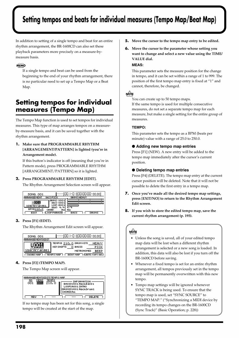
1
Setting tempos and beats for individual measures (Tempo Map/Beat Map)
In addition to setting of a single tempo and beat for an entire rhythm arrangement, the BR-1600CD can also set these playback parameters more precisely on a measure-by-measure basis.
If a single tempo and beat can be used from the beginning to the end of your rhythm arrangement, there is no particular need to set up a Tempo Map or a Beat Map.
Setting tempos for individual measures (Tempo Map)The Tempo Map function is used to set tempos for individual measures. This type of map arranges tempos on a measure-by-measure basis, and it can be saved together with the rhythm arrangement.
1. Make sure that PROGRAMMABLE RHYTHM [ARRANGEMENT/PATTERN] is lighted (you’re in Arrangement mode).
If this button’s indicator is off (meaning that you’re in Pattern mode), press PROGRAMMABLE RHYTHM [ARRANGEMENT/PATTERN] so it is lighted.
2. Press PROGRAMMABLE RHYTHM [EDIT].
The Rhythm Arrangement Selection screen will appear.fig.21-33d
3. Press [F1] (EDIT).
The Rhythm Arrangement Edit screen will appear.fig.21-34d
4. Press [F2] (TEMPO MAP).
The Tempo Map screen will appear.fig.21-35d
If no tempo map has been set for this song, a single tempo will be created at the start of the map.
5. Move the cursor to the tempo map entry to be edited.
6. Move the cursor to the parameter whose setting you want to change and select a new value using the TIME/VALUE dial.
MEAS:
This parameter sets the measure position for the change in tempo, and it can be set within a range of 1 to 999. The position of the first tempo map entry is fixed at “1” and cannot, therefore, be changed.
You can create up to 50 tempo maps.If the same tempo is used for multiple consecutive measures, do not set a separate tempo map for each measure, but make a single setting for the entire group of measures.
TEMPO:
This parameter sets the tempo as a BPM (beats per minute) value with a range of 25.0 to 250.0.
Adding new tempo map entriesPress [F1] (NEW). A new entry will be added to the tempo map immediately after the cursor’s current position.
Deleting tempo map entriesPress [F4] (DELETE). The tempo map entry at the current cursor position will be deleted. Note that it will not be possible to delete the first entry in a tempo map.
7. Once you’ve made all the desired tempo map settings, press [EXIT/NO] to return to the Rhythm Arrangement Edit screen.
8. If you wish to store the edited tempo map, save the current rhythm arrangement (p. 195).
• Unless the song is saved, all of your edited tempo map data will be lost when a different rhythm arrangement is selected or a new song is loaded. In addition, this data will also be lost if you turn off the BR-1600CD before saving.
• Whenever a fixed tempo is set for an entire rhythm arrangement, all tempos previously set in the tempo map will be permanently overwritten with this new tempo.
• Tempo map settings will be ignored whenever SYNC TRACK is being used. To ensure that the tempo map is used, set “SYNC SOURCE” to “TEMPO MAP.” (“Synchronizing a MIDI device by recording its tempo changes on the BR-1600CD (Sync Track)” (Basic Operation; p. 228))
98
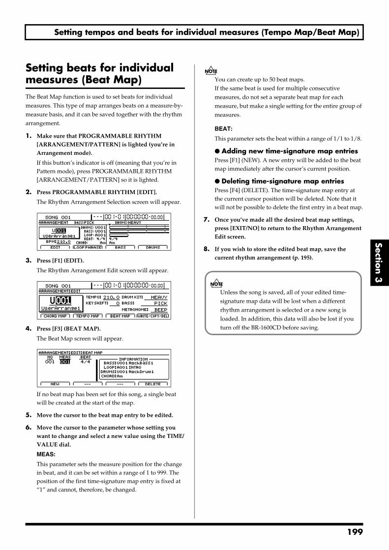
Setting tempos and beats for individual measures (Tempo Map/Beat Map)
Section 3
Setting beats for individual measures (Beat Map)The Beat Map function is used to set beats for individual measures. This type of map arranges beats on a measure-by-measure basis, and it can be saved together with the rhythm arrangement.
1. Make sure that PROGRAMMABLE RHYTHM [ARRANGEMENT/PATTERN] is lighted (you’re in Arrangement mode).
If this button’s indicator is off (meaning that you’re in Pattern mode), press PROGRAMMABLE RHYTHM [ARRANGEMENT/PATTERN] so it is lighted.
2. Press PROGRAMMABLE RHYTHM [EDIT].
The Rhythm Arrangement Selection screen will appear.fig.21-33d
3. Press [F1] (EDIT).
The Rhythm Arrangement Edit screen will appear.fig.21-37d
4. Press [F3] (BEAT MAP).
The Beat Map screen will appear.fig.21-38d
If no beat map has been set for this song, a single beat will be created at the start of the map.
5. Move the cursor to the beat map entry to be edited.
6. Move the cursor to the parameter whose setting you want to change and select a new value using the TIME/VALUE dial.
MEAS:
This parameter sets the measure position for the change in beat, and it can be set within a range of 1 to 999. The position of the first time-signature map entry is fixed at “1” and cannot, therefore, be changed.
You can create up to 50 beat maps.If the same beat is used for multiple consecutive measures, do not set a separate beat map for each measure, but make a single setting for the entire group of measures.
BEAT:
This parameter sets the beat within a range of 1/1 to 1/8.
Adding new time-signature map entriesPress [F1] (NEW). A new entry will be added to the beat map immediately after the cursor’s current position.
Deleting time-signature map entriesPress [F4] (DELETE). The time-signature map entry at the current cursor position will be deleted. Note that it will not be possible to delete the first entry in a beat map.
7. Once you’ve made all the desired beat map settings, press [EXIT/NO] to return to the Rhythm Arrangement Edit screen.
8. If you wish to store the edited beat map, save the current rhythm arrangement (p. 195).
Unless the song is saved, all of your edited time-signature map data will be lost when a different rhythm arrangement is selected or a new song is loaded. In addition, this data will also be lost if you turn off the BR-1600CD before saving.
199
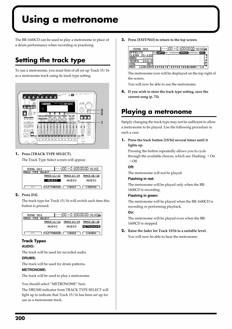
2
Using a metronome
The BR-1600CD can be used to play a metronome in place of a drum performance when recording or practicing.
Setting the track typeTo use a metronome, you must first of all set up Track 15/16 as a metronome track using its track type setting. fig.21-39
1. Press [TRACK TYPE SELECT].
The Track Type Select screen will appear.fig.21-40d
2. Press [F4].
The track type for Track 15/16 will switch each time this button is pressed.
fig.21-41d
Track TypesAUDIO:
The track will be used for recorded audio.
DRUMS:
The track will be used for drum patterns.
METRONOME:
The track will be used to play a metronome.
You should select “METRONOME” here.
The DRUMS indicator from TRACK TYPE SELECT will light up to indicate that Track 15/16 has been set up for use as a metronome track.
3. Press [EXIT/NO] to return to the top screen.fig.21-42d
The metronome icon will be displayed on the top right of the screen.
You will now be able to use the metronome.
4. If you wish to store the track type setting, save the current song (p. 72).
Playing a metronomeSimply changing the track type may not be sufficient to allow a metronome to be played. Use the following procedure in such a case.
1. Press the track button [15/16] several times until it lights up.
Pressing the button repeatedly allows you to cycle through the available choices, which are: Flashing → On → Off.
Off:
The metronome will not be played.
Flashing in red:
The metronome will be played only when the BR-1600CD is recording.
Flashing in green:
The metronome will be played when the BR-1600CD is recording or performing playback.
On:
The metronome will be played even when the BR-1600CD is stopped.
2. Raise the fader for Track 15/16 to a suitable level.
You will now be able to hear the metronome.
32
1
00
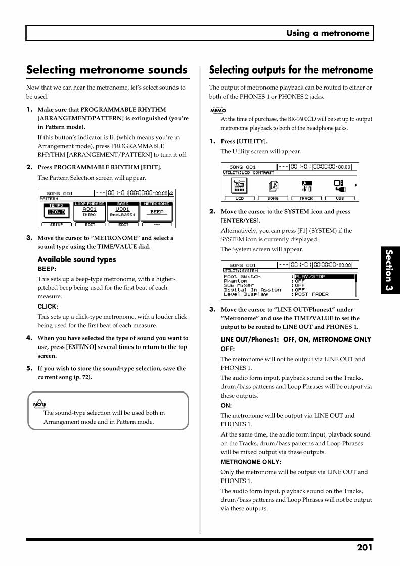
Using a metronome
Section 3
Selecting metronome soundsNow that we can hear the metronome, let’s select sounds to be used.
1. Make sure that PROGRAMMABLE RHYTHM [ARRANGEMENT/PATTERN] is extinguished (you’re in Pattern mode).
If this button’s indicator is lit (which means you’re in Arrangement mode), press PROGRAMMABLE RHYTHM [ARRANGEMENT/PATTERN] to turn it off.
2. Press PROGRAMMABLE RHYTHM [EDIT].
The Pattern Selection screen will appear.fig.21-43d
3. Move the cursor to “METRONOME” and select a sound type using the TIME/VALUE dial.
Available sound typesBEEP:
This sets up a beep-type metronome, with a higher-pitched beep being used for the first beat of each measure.
CLICK:
This sets up a click-type metronome, with a louder click being used for the first beat of each measure.
4. When you have selected the type of sound you want to use, press [EXIT/NO] several times to return to the top screen.
5. If you wish to store the sound-type selection, save the current song (p. 72).
Selecting outputs for the metronomeThe output of metronome playback can be routed to either or both of the PHONES 1 or PHONES 2 jacks.
At the time of purchase, the BR-1600CD will be set up to output metronome playback to both of the headphone jacks.
1. Press [UTILITY].
The Utility screen will appear.fig.21-45d
2. Move the cursor to the SYSTEM icon and press [ENTER/YES].
Alternatively, you can press [F1] (SYSTEM) if the SYSTEM icon is currently displayed.
The System screen will appear.fig.10-03d
3. Move the cursor to “LINE OUT/Phones1” under “Metronome” and use the TIME/VALUE to set the output to be routed to LINE OUT and PHONES 1.
LINE OUT/Phones1: OFF, ON, METRONOME ONLYOFF:
The metronome will not be output via LINE OUT and PHONES 1.
The audio form input, playback sound on the Tracks, drum/bass patterns and Loop Phrases will be output via these outputs.
ON:
The metronome will be output via LINE OUT and PHONES 1.
At the same time, the audio form input, playback sound on the Tracks, drum/bass patterns and Loop Phrases will be mixed output via these outputs.
METRONOME ONLY:
Only the metronome will be output via LINE OUT and PHONES 1.
The audio form input, playback sound on the Tracks, drum/bass patterns and Loop Phrases will not be output via these outputs.
The sound-type selection will be used both in Arrangement mode and in Pattern mode.
201
Using a metronome
4. Move the cursor to “Phones2” under “Metronome” and use the TIME/VALUE to set the output to be routed to PHONES 2.
Phones2: OFF, ON, METRONOME ONLYOFF:
The metronome will not be output via PHONES 2.
The audio form input, playback sound on the Tracks, drum/bass patterns and Loop Phrases will be output via this output.
ON:
The metronome will be output via PHONES 2.
At the same time, the audio form input, playback sound on the Tracks, drum/bass patterns and Loop Phrases will be mixed output via this output.
METRONOME ONLY:
Only the metronome will be output via PHONES 2.
The audio form input, playback sound on the Tracks, drum/bass patterns and Loop Phrases will not be output via this output.
At the time of purchase, both LINE OUT/PHONES 1 and PHONES 2 will be set to “ON.”
202
Section 4 Using the CD-R/RW Drive
Section 4Using the CD-R/RW
Drive
203
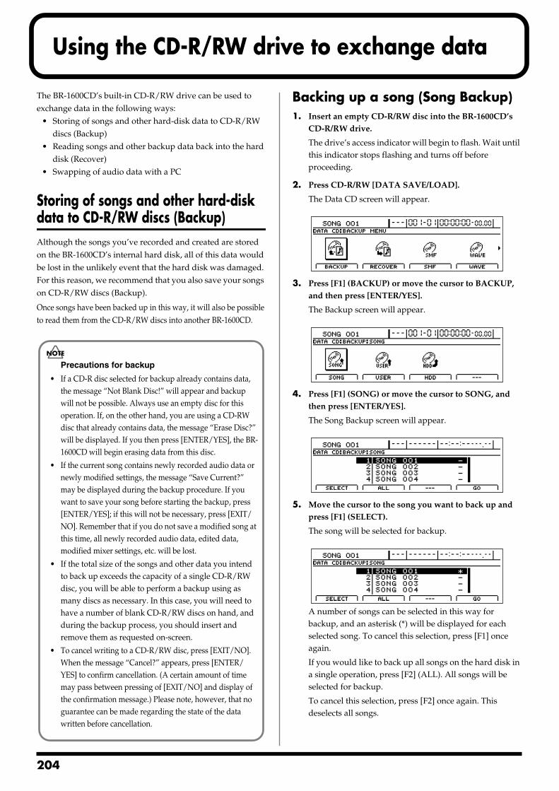
2
Using the CD-R/RW drive to exchange data
The BR-1600CD’s built-in CD-R/RW drive can be used to exchange data in the following ways:
• Storing of songs and other hard-disk data to CD-R/RW discs (Backup)
• Reading songs and other backup data back into the hard disk (Recover)
• Swapping of audio data with a PC
Storing of songs and other hard-disk data to CD-R/RW discs (Backup)Although the songs you’ve recorded and created are stored on the BR-1600CD’s internal hard disk, all of this data would be lost in the unlikely event that the hard disk was damaged. For this reason, we recommend that you also save your songs on CD-R/RW discs (Backup).
Once songs have been backed up in this way, it will also be possible to read them from the CD-R/RW discs into another BR-1600CD.
Backing up a song (Song Backup)1. Insert an empty CD-R/RW disc into the BR-1600CD’s
CD-R/RW drive.
The drive’s access indicator will begin to flash. Wait until this indicator stops flashing and turns off before proceeding.
2. Press CD-R/RW [DATA SAVE/LOAD].
The Data CD screen will appear.fig.41-05d
3. Press [F1] (BACKUP) or move the cursor to BACKUP, and then press [ENTER/YES].
The Backup screen will appear.fig.41-01d
4. Press [F1] (SONG) or move the cursor to SONG, and then press [ENTER/YES].
The Song Backup screen will appear.fig.41-02d
5. Move the cursor to the song you want to back up and press [F1] (SELECT).
The song will be selected for backup.fig.41-02ad
A number of songs can be selected in this way for backup, and an asterisk (*) will be displayed for each selected song. To cancel this selection, press [F1] once again.
If you would like to back up all songs on the hard disk in a single operation, press [F2] (ALL). All songs will be selected for backup.
To cancel this selection, press [F2] once again. This deselects all songs.
Precautions for backup
• If a CD-R disc selected for backup already contains data, the message “Not Blank Disc!” will appear and backup will not be possible. Always use an empty disc for this operation. If, on the other hand, you are using a CD-RW disc that already contains data, the message “Erase Disc?” will be displayed. If you then press [ENTER/YES], the BR-1600CD will begin erasing data from this disc.
• If the current song contains newly recorded audio data or newly modified settings, the message “Save Current?” may be displayed during the backup procedure. If you want to save your song before starting the backup, press [ENTER/YES]; if this will not be necessary, press [EXIT/NO]. Remember that if you do not save a modified song at this time, all newly recorded audio data, edited data, modified mixer settings, etc. will be lost.
• If the total size of the songs and other data you intend to back up exceeds the capacity of a single CD-R/RW disc, you will be able to perform a backup using as many discs as necessary. In this case, you will need to have a number of blank CD-R/RW discs on hand, and during the backup process, you should insert and remove them as requested on-screen.
• To cancel writing to a CD-R/RW disc, press [EXIT/NO]. When the message “Cancel?” appears, press [ENTER/YES] to confirm cancellation. (A certain amount of time may pass between pressing of [EXIT/NO] and display of the confirmation message.) Please note, however, that no guarantee can be made regarding the state of the data written before cancellation.
04
Using the CD-R/RW drive to exchange data
Section 4
6. When you have selected all of the songs you want to back up, press [F4] (GO).
The message “Write Speed?” will appear.fig.41-03d
7. Use the TIME/VALUE dial to set the write speed.
Write Speed:
x2 (352 Kbps) Writes twice as fast.
x4 (704 Kbps) Writes four times as fast.
x8 (1408 Kbps) Writes eight times as fast.
• The range of available write speeds can sometimes be limited by the type of disc being used. In such cases, the BR-1600CD will allow you to select only the supported speeds using the TIME/VALUE dial.
• If you are using CD-R/RW discs intended for high-speed writing, the frequency of write errors may increase if the x2 or x4 speed is selected. It is recommended that you use the x8 speed for high-speed discs.
8. Press [ENTER/YES].
If you want to cancel the backup, press [EXIT/NO].
The message “Write Sure?” will appear.fig.41-04d
9. Press [ENTER/YES] once again.
The BR-1600CD will begin writing data to the CD-R/RW disc.
When the message “Complete!” appears, it indicates that the backup has been successfully completed.
Backing up user data (User Backup)The BR-1600CD allows you to back up the following types of user data to CD-R/RW discs.
• Insert effect patches
• Mastering Tool Kit patches
• Speaker Modeling patches
• Vocal Tool Box patches
• Rhythm arrangements, drum patterns, bass patterns, and loop phrases
1. Insert an empty CD-R/RW disc into the BR-1600CD’s CD-R/RW drive.
The drive’s access indicator will begin to flash. Wait until this indicator stops flashing and turns off before proceeding.
2. Press CD-R/RW [DATA SAVE/LOAD].
The Data CD screen will appear.fig.41-05d
3. Press [F1] (BACKUP) or move the cursor to the BACKUP icon, and then press [ENTER/YES].
The Backup screen will appear.fig.41-01d
4. Press [F2] (USER) or move the cursor to USER, and then press [ENTER/YES].
The User Backup screen will appear.fig.41-07d
5. Move the cursor to the type of data you want to back up and press [F1] (SELECT).
The data will selected for backup.
205
Using the CD-R/RW drive to exchange data
fig.41-07ad
A number of types of data can be selected in this way for backup, and an asterisk (*) will be displayed for each selected type. To cancel a selection, simply press [F1] once again.
Data that can be backed up:Effects/Arrangement/Drums&Bass Pattern:
• Insert Effects User Patches
• Vocal Tool Box User Patches
• Mastering User Kit User Patches
• Speaker Modeling User Patches
• User Rhythm Arrangement
• User drum pattern
• User bass pattern
The data described above will all be saved.
Loop Phrase:
User loop phrases will all be saved.
If you would like to back up all such data on the hard disk in a single operation, press [F2] (ALL). All data types will be selected for backup.
To cancel this selection, press [F2] once again. This deselects all data types.
6. When you have selected all of the data you want to back up, press [F4] (GO).
The message “Write Speed?” will appear.fig.41-08d
7. Use the TIME/VALUE dial to set the write speed.
Write Speed:
x2 (352 Kbps) Writes twice as fast.
x4 (704 Kbps) Writes four times as fast.
x8 (1408 Kbps) Writes eight times as fast.
• The range of available write speeds can sometimes be limited by the type of disc being used. In such cases, the BR-1600CD will allow you to select only the supported speeds using the TIME/VALUE dial.
• If you are using CD-R/RW discs intended for high-speed writing, the frequency of write errors may increase if the x2 or x4 speed is selected. It is recommended that you use the x8 speed for high-speed discs.
8. Press [ENTER/YES].
If you want to cancel the backup, press [EXIT/NO].
The message “Write Sure?” will appear.fig.41-09d
9. Press [ENTER/YES] once again.
The BR-1600CD will begin writing data to the CD-R/RW disc. When the message “Complete!” appears, it indicates that the backup has been successfully completed.
Backing up all data on the hard disk (HDD Backup)The BR-1600CD allows you to back up all of the data on the internal hard disk onto CD-R/RW discs, regardless of the type of data or the song in which it is used. Data that’s been backed up this way can later be recovered whenever needed.
Note, however, that this type of backup is limited to the data contained in the currently selected drive or partition. If you would also like to back up data from another drive or partition, you will need to change the current drive first. Note also that recovered data will be stored on the currently selected drive.
1. Insert an empty CD-R/RW disc into the BR-1600CD’s CD-R/RW drive.
The drive’s access indicator will begin to flash. Wait until this indicator stops flashing and turns off before proceeding.
2. Press CD-R/RW [DATA SAVE/LOAD].
The Data CD screen will appear.fig.41-05d
206
Using the CD-R/RW drive to exchange data
Section 4
3. Press [F1] (BACKUP) or move the cursor to BACKUP, and then press [ENTER/YES].
The Backup screen will appear.fig.41-01d
4. Press [F3] (HDD) or move the cursor to HDD, and then press [ENTER/YES].
The message “HDD Backup OK?” will appear.fig.41-12d
5. Press [ENTER/YES].
The message “Write Speed?” will appear.fig.41-13d
6. Use the TIME/VALUE dial to set the write speed.
Write Speed:
x2 (352 Kbps) Writes twice as fast.
x4 (704 Kbps) Writes four times as fast.
x8 (1408 Kbps) Writes eight times as fast.
• The range of available write speeds can sometimes be limited by the type of disc being used. In such cases, the BR-1600CD will allow you to select only the supported speeds using the TIME/VALUE dial.
• If you are using CD-R/RW discs intended for high-speed writing, the frequency of write errors may increase if the x2 or x4 speed is selected. It is recommended that you use the x8 speed for high-speed discs.
7. Press [ENTER/YES].
If you want to cancel the backup, press [EXIT/NO].
The message “Write Sure?” will appear.fig.41-14d
8. Press [ENTER/YES] once again.
The BR-1600CD will begin writing data to the CD-R/RW disc. When the message “Complete!” appears, it indicates that the backup has been successfully completed.
Reading songs and other backup data back into the hard disk (Recover)
Notes concerning recovery
• You will not be able to select any songs or data types that have not been saved to the CD-R/RW disc.
• If the current song contains newly recorded audio data or newly modified settings, the message “Save Current?” may be displayed during the recovery procedure. If you want to save your song before starting the recover process, press [ENTER/YES]; if this will not be necessary, press [EXIT/NO]. Remember that if you do not save a modified song at this time, all newly recorded audio data, edited data, modified mixer settings, etc. will be lost.
• To cancel reading from a CD-R/RW disc, press [EXIT/NO]. When the message “Cancel?” appears, press [ENTER/YES] to confirm cancellation. (A certain amount of time may pass between pressing of [EXIT/NO] and display of the confirmation message.)
• If the total size of the songs and other data to be recovered exceeds the amount of space available on the hard disk, the message “HDD Full!” will be displayed and the reading of data will not be possible. In such a case, you should reduce the number of songs or the volume of data to be recovered, or alternatively, you should free up some hard disk space by deleting unneeded data and/or songs.
Reading backup songs back into the hard disk (Song Recover)1. Insert a CD-R/RW disc containing backup songs into
the BR-1600CD’s CD-R/RW drive.
The drive’s access indicator will begin to flash. Wait until this indicator stops flashing and turns off before proceeding.
2. Press CD-R/RW [DATA SAVE/LOAD].
The Data CD screen will appear.fig.41-05d
207

Using the CD-R/RW drive to exchange data
3. Press [F2] (RECOVER) or move the cursor to RECOVER, and then press [ENTER/YES].
The Recover screen will appear.fig.41-16d
4. Press [F1] (SONG) or move the cursor to SONG, and then press [ENTER/YES].
A list of the CD-R/RW disc’s backup songs will be displayed.
fig.41-17d
5. Move the cursor to the song you want to recover and press [F1] (SELECT).
The song will selected for recovery.
A number of songs can be selected in this way for recovery, and an asterisk (*) will be displayed for each selected song. To cancel this selection, press [F2] once again.
If you would like to recover all of the songs on the CD-R/RW disc in a single operation, press [F2] (ALL). All songs will be selected for recovery.
To cancel this selection, press [F2] once again. This deselects all songs.
6. When you have selected all of the songs you want to recover, press [F4] (GO).
The BR-1600CD will start the recovery process. When the message “Complete!” appears, it indicates that the recovery has been completed successfully.
Reading backup user data back into the hard disk (User Recover)1. Insert a CD-R/RW disc containing backup user data
into the BR-1600CD’s CD-R/RW drive.
The drive’s access indicator will begin to flash. Wait until this indicator stops flashing and turns off before proceeding.
2. Press CD-R/RW [DATA SAVE/LOAD].
The Data CD screen will appear.fig.41-05d
3. Press [F2] (RECOVER) or move the cursor to RECOVER, and then press [ENTER/YES].
The Recover screen will appear.fig.41-16d
4. Press [F2] (USER) or move the cursor to USER, and then press [ENTER/YES].
fig.41-20d
5. Use the TIME/VALUE dial to select the data you want to recover.
If you select the data that has no backup data, “*EMPTY” will be displayed.
Data that can be recovered:ALL
All of the user data on the CD-R/RW disc
EFFECTS
All insert effects patches from the user bank will be recovered.
MASTERING TOOL KIT
The Mastering Tool Kit’s user bank will be recovered.
SPEAKER MODELING
The Speaker Modeling user bank will be recovered.
VOCAL TOOL BOX
The Vocal Tool Box’s user bank will be recovered.
The recovered songs will be saved in sequence on the hard disk using the available song numbers.
208
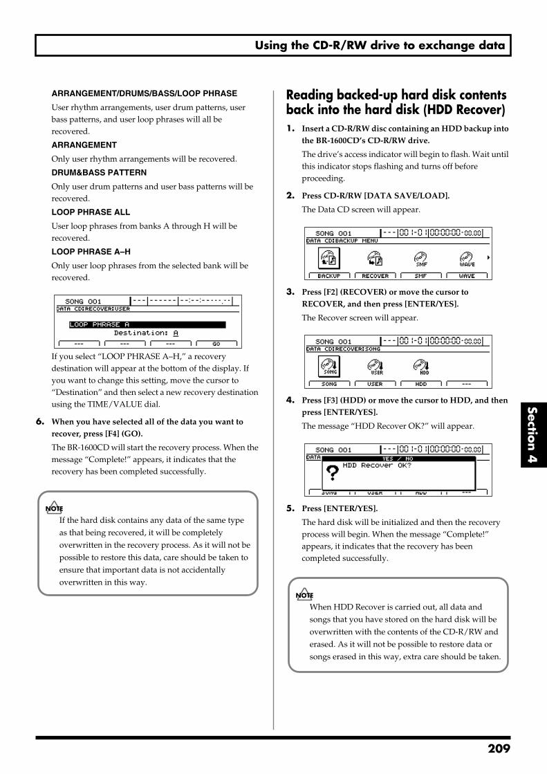
Using the CD-R/RW drive to exchange data
Section 4
ARRANGEMENT/DRUMS/BASS/LOOP PHRASE
User rhythm arrangements, user drum patterns, user bass patterns, and user loop phrases will all be recovered.
ARRANGEMENT
Only user rhythm arrangements will be recovered.
DRUM&BASS PATTERN
Only user drum patterns and user bass patterns will be recovered.
LOOP PHRASE ALL
User loop phrases from banks A through H will be recovered.
LOOP PHRASE A–H
Only user loop phrases from the selected bank will be recovered.
fig.41-21d_recoveruserlphall.bmp
If you select “LOOP PHRASE A–H,” a recovery destination will appear at the bottom of the display. If you want to change this setting, move the cursor to “Destination” and then select a new recovery destination using the TIME/VALUE dial.
6. When you have selected all of the data you want to recover, press [F4] (GO).
The BR-1600CD will start the recovery process. When the message “Complete!” appears, it indicates that the recovery has been completed successfully.
Reading backed-up hard disk contents back into the hard disk (HDD Recover)1. Insert a CD-R/RW disc containing an HDD backup into
the BR-1600CD’s CD-R/RW drive.
The drive’s access indicator will begin to flash. Wait until this indicator stops flashing and turns off before proceeding.
2. Press CD-R/RW [DATA SAVE/LOAD].
The Data CD screen will appear.fig.41-05d
3. Press [F2] (RECOVER) or move the cursor to RECOVER, and then press [ENTER/YES].
The Recover screen will appear.fig.41-16d
4. Press [F3] (HDD) or move the cursor to HDD, and then press [ENTER/YES].
The message “HDD Recover OK?” will appear.fig.41-24d
5. Press [ENTER/YES].
The hard disk will be initialized and then the recovery process will begin. When the message “Complete!” appears, it indicates that the recovery has been completed successfully.
If the hard disk contains any data of the same type as that being recovered, it will be completely overwritten in the recovery process. As it will not be possible to restore this data, care should be taken to ensure that important data is not accidentally overwritten in this way.
When HDD Recover is carried out, all data and songs that you have stored on the hard disk will be overwritten with the contents of the CD-R/RW and erased. As it will not be possible to restore data or songs erased in this way, extra care should be taken.
209

2
Copying and writing waveform data
If you have a computer equipped with a CD-R/RW drive, you can use CD-R/RW discs to transfer waveform data between multiple BR-1600CDs.
You can, for example, use these discs to copy waveform data created with the audio software on your computer and then paste the data to audio tracks. You can also take audio track data recorded with the BR-1600CD and copy it to your computer for editing.
Copying waveform data from a computer to the audio tracks (WAV/AIFF Import)
1. Using a PC, burn and finalize a CD-R/RW disc containing the audio data that you want to import.
For instructions on how to write waveform data to CD-R/RW discs, refer to your computer and CD-R/RW drive owner’s manuals.
2. Place the CD-R/RW disc containing the copied hard disk data in the BR-1600CD’s CD-R/RW drive.
The drive’s access indicator will begin to flash. Wait until this indicator stops flashing and turns off before proceeding.
3. Press [DATA SAVE/LOAD].
The Data CD screen will appear.fig.41-05d
4. Press [F4] (WAVE).
The WAV/AIFF screen will appear.fig.R16-07
5. Press [F1] (IMPORT).
A list of the audio data files contained on the current CD-R/RW disc will appear.
fig.R16-56d
If the WAV files are collected in a folder, then the folder
name and icon ( ) is displayed. To show the WAV files within the folder, move the cursor to the folder name and press [ENTER/YES].
fig.R16-94d
6. To switch the format of the wave file you want to import, press [F1] (TYPE).
[F1] acts as a toggle, switching the file format between WAV and AIFF each time it’s pressed.
This procedure requires a computer equipped with a drive capable of writing to CD-R/RW discs.
If the current song contains newly recorded audio data or newly modified settings, or if an import has been carried out, the message “Save Current?” may be displayed during this procedure.If you want to save your song before starting the import process, press [ENTER/YES]; if this will not be necessary, press [EXIT/NO].Remember that if you do not save a modified song at this time, all newly recorded audio data, edited settings, imported data, etc. will be lost.
To be eligible for import, waveform data must meet the following criteria. In most cases, you will not be able to import other kinds of data.
• Use “ISO 9660 Level 2, Mode 1” to write the data to the CD-R/RW disc.
• Audio data must be of WAV or AIFF format, in stereo or mono, and with an uncompressed bit depth of 8 or 16 bits. Furthermore, the sampling rate must be 44.1 kHz.
• Audio data must be at least 500 ms in length.
• Name waveform data using eight letters followed by a less than three-character extension.
• The loop point settings within an AIFF file will be ignored.
10
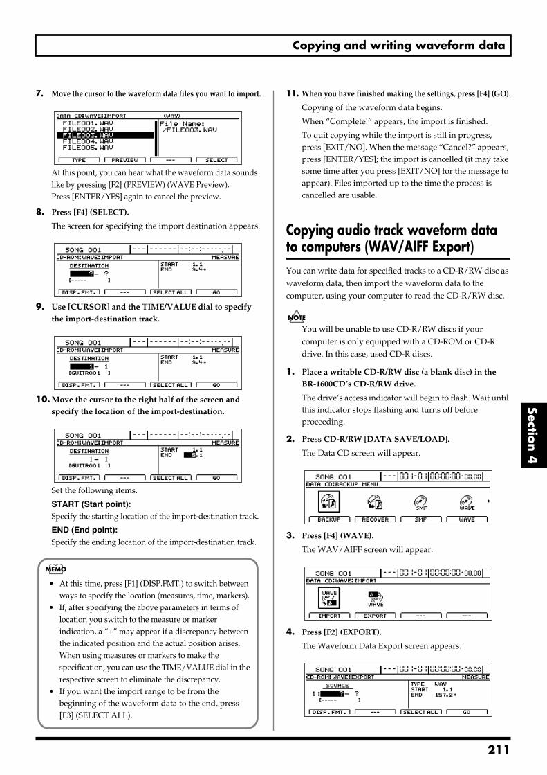
Copying and writing waveform data
Section 4
7. Move the cursor to the waveform data files you want to import.fig.R16-08ad
At this point, you can hear what the waveform data sounds like by pressing [F2] (PREVIEW) (WAVE Preview).Press [ENTER/YES] again to cancel the preview.
8. Press [F4] (SELECT).
The screen for specifying the import destination appears.fig.R16-08d
9. Use [CURSOR] and the TIME/VALUE dial to specify the import-destination track.
fig.R16-08bd
10. Move the cursor to the right half of the screen and specify the location of the import-destination.
fig.R16-08cd
Set the following items.
START (Start point):Specify the starting location of the import-destination track.
END (End point):Specify the ending location of the import-destination track.
11. When you have finished making the settings, press [F4] (GO).
Copying of the waveform data begins.
When “Complete!” appears, the import is finished.
To quit copying while the import is still in progress, press [EXIT/NO]. When the message “Cancel?” appears, press [ENTER/YES]; the import is cancelled (it may take some time after you press [EXIT/NO] for the message to appear). Files imported up to the time the process is cancelled are usable.
Copying audio track waveform data to computers (WAV/AIFF Export)You can write data for specified tracks to a CD-R/RW disc as waveform data, then import the waveform data to the computer, using your computer to read the CD-R/RW disc.
You will be unable to use CD-R/RW discs if your computer is only equipped with a CD-ROM or CD-R drive. In this case, used CD-R discs.
1. Place a writable CD-R/RW disc (a blank disc) in the BR-1600CD’s CD-R/RW drive.
The drive’s access indicator will begin to flash. Wait until this indicator stops flashing and turns off before proceeding.
2. Press CD-R/RW [DATA SAVE/LOAD].
The Data CD screen will appear.fig.41-05d
3. Press [F4] (WAVE).
The WAV/AIFF screen will appear.fig.R16-07d
4. Press [F2] (EXPORT).
The Waveform Data Export screen appears.fig.R16-10d
• At this time, press [F1] (DISP.FMT.) to switch between ways to specify the location (measures, time, markers).
• If, after specifying the above parameters in terms of location you switch to the measure or marker indication, a “+” may appear if a discrepancy between the indicated position and the actual position arises. When using measures or markers to make the specification, you can use the TIME/VALUE dial in the respective screen to eliminate the discrepancy.
• If you want the import range to be from the beginning of the waveform data to the end, press [F3] (SELECT ALL).
211
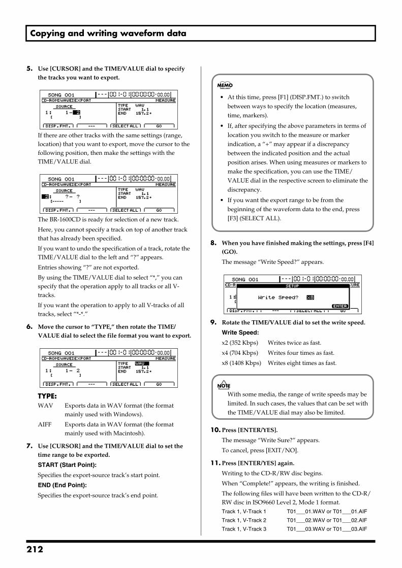
Copying and writing waveform data
5. Use [CURSOR] and the TIME/VALUE dial to specify the tracks you want to export.
fig.R16-11ad
If there are other tracks with the same settings (range, location) that you want to export, move the cursor to the following position, then make the settings with the TIME/VALUE dial.
fig.R16-11d
The BR-1600CD is ready for selection of a new track.
Here, you cannot specify a track on top of another track that has already been specified.
If you want to undo the specification of a track, rotate the TIME/VALUE dial to the left and “?” appears.
Entries showing “?” are not exported.
By using the TIME/VALUE dial to select “*,” you can specify that the operation apply to all tracks or all V-tracks.
If you want the operation to apply to all V-tracks of all tracks, select “*-*.”
6. Move the cursor to “TYPE,” then rotate the TIME/VALUE dial to select the file format you want to export.
fig.R16-11bd
TYPE:WAV Exports data in WAV format (the format
mainly used with Windows).
AIFF Exports data in WAV format (the format mainly used with Macintosh).
7. Use [CURSOR] and the TIME/VALUE dial to set the time range to be exported.
START (Start Point):
Specifies the export-source track’s start point.
END (End Point):
Specifies the export-source track’s end point.
8. When you have finished making the settings, press [F4] (GO).
The message “Write Speed?” appears.fig.R16-93d
9. Rotate the TIME/VALUE dial to set the write speed.
Write Speed:
x2 (352 Kbps) Writes twice as fast.
x4 (704 Kbps) Writes four times as fast.
x8 (1408 Kbps) Writes eight times as fast.
10. Press [ENTER/YES].
The message “Write Sure?” appears.
To cancel, press [EXIT/NO].
11. Press [ENTER/YES] again.
Writing to the CD-R/RW disc begins.
When “Complete!” appears, the writing is finished.
The following files will have been written to the CD-R/RW disc in ISO9660 Level 2, Mode 1 format.Track 1, V-Track 1 T01___01.WAV or T01___01.AIF
Track 1, V-Track 2 T01___02.WAV or T01___02.AIF
Track 1, V-Track 3 T01___03.WAV or T01___03.AIF
• At this time, press [F1] (DISP.FMT.) to switch between ways to specify the location (measures, time, markers).
• If, after specifying the above parameters in terms of location you switch to the measure or marker indication, a “+” may appear if a discrepancy between the indicated position and the actual position arises. When using measures or markers to make the specification, you can use the TIME/VALUE dial in the respective screen to eliminate the discrepancy.
• If you want the export range to be from the beginning of the waveform data to the end, press [F3] (SELECT ALL).
With some media, the range of write speeds may be limited. In such cases, the values that can be set with the TIME/VALUE dial may also be limited.
212
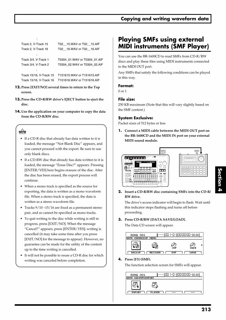
Copying and writing waveform data
Section 4
:
Track 2, V-Track 15 T02__15.WAV or T02__15.AIF
Track 2, V-Track 16 T02__16.WAV or T02__16.AIF
:Track 3/4, V-Track 1 T0304_01.WAV or T0304_01.AIF
Track 3/4, V-Track 2 T0304_02.WAV or T0304_02.AIF
:Track 15/16, V-Track 15 T151615.WAV or T151615.AIF
Track 15/16, V-Track 16 T151616.WAV or T151616.AIF
12. Press [EXIT/NO] several times to return to the Top screen.
13. Press the CD-R/RW drive’s EJECT button to eject the disc.
14. Use the application on your computer to copy the data from the CD-R/RW disc.
Playing SMFs using external MIDI instruments (SMF Player)You can use the BR-1600CD to read SMFs from CD-R/RW discs and play these files using MIDI instruments connected to the MIDI OUT port.
Any SMFs that satisfy the following conditions can be played in this way.
Format:0 or 1
File size:250 KB maximum (Note that this will vary slightly based on the SMF content.)
System Exclusive: Packet sizes of 512 bytes or less
1. Connect a MIDI cable between the MIDI OUT port on the BR-1600CD and the MIDI IN port on your external MIDI sound module.
fig.41-25
2. Insert a CD-R/RW disc containing SMFs into the CD-R/RW drive.
The drive’s access indicator will begin to flash. Wait until this indicator stops flashing and turns off before proceeding.
3. Press CD-R/RW [DATA SAVE/LOAD].
The Data CD screen will appear.fig.41-05d
4. Press [F3] (SMF).
The function selection screen for SMFs will appear.fig.41-27d
• If a CD-R disc that already has data written to it is loaded, the message “Not Blank Disc” appears, and you cannot proceed with the export. Be sure to use only blank discs.
• If a CD-RW disc that already has data written to it is loaded, the message “Erase Disc?” appears. Pressing [ENTER/YES] here begins erasure of the disc. After the disc has been erased, the export process will continue.
• When a mono track is specified as the source for exporting, the data is written as a mono waveform file. When a stereo track is specified, the data is written as a stereo waveform file.
• Tracks 9/10 –15/16 are fixed as a permanent stereo pair, and so cannot be specified as mono tracks.
• To quit writing to the disc while writing is still in progress, press [EXIT/NO]. When the message “Cancel?” appears, press [ENTER/YES]; writing is cancelled (it may take some time after you press [EXIT/NO] for the message to appear). However, no guarantee can be made for the utility of the content up to the time writing is cancelled.
• It will not be possible to reuse a CD-R disc for which writing was canceled before completion.
MIDIIN
MIDIOUT
213
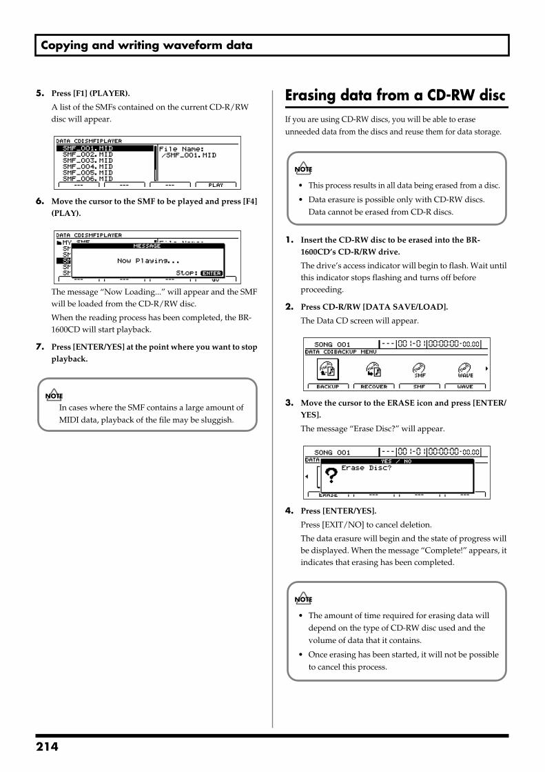
Copying and writing waveform data
5. Press [F1] (PLAYER).
A list of the SMFs contained on the current CD-R/RW disc will appear.
fig.41-28d
6. Move the cursor to the SMF to be played and press [F4] (PLAY).
fig.41-28ad
The message “Now Loading...” will appear and the SMF will be loaded from the CD-R/RW disc.
When the reading process has been completed, the BR-1600CD will start playback.
7. Press [ENTER/YES] at the point where you want to stop playback.
Erasing data from a CD-RW discIf you are using CD-RW discs, you will be able to erase unneeded data from the discs and reuse them for data storage.
1. Insert the CD-RW disc to be erased into the BR-1600CD’s CD-R/RW drive.
The drive’s access indicator will begin to flash. Wait until this indicator stops flashing and turns off before proceeding.
2. Press CD-R/RW [DATA SAVE/LOAD].
The Data CD screen will appear.fig.41-05d
3. Move the cursor to the ERASE icon and press [ENTER/YES].
The message “Erase Disc?” will appear.fig.41-31d
4. Press [ENTER/YES].
Press [EXIT/NO] to cancel deletion.
The data erasure will begin and the state of progress will be displayed. When the message “Complete!” appears, it indicates that erasing has been completed.
In cases where the SMF contains a large amount of MIDI data, playback of the file may be sluggish.
• This process results in all data being erased from a disc.
• Data erasure is possible only with CD-RW discs. Data cannot be erased from CD-R discs.
• The amount of time required for erasing data will depend on the type of CD-RW disc used and the volume of data that it contains.
• Once erasing has been started, it will not be possible to cancel this process.
214
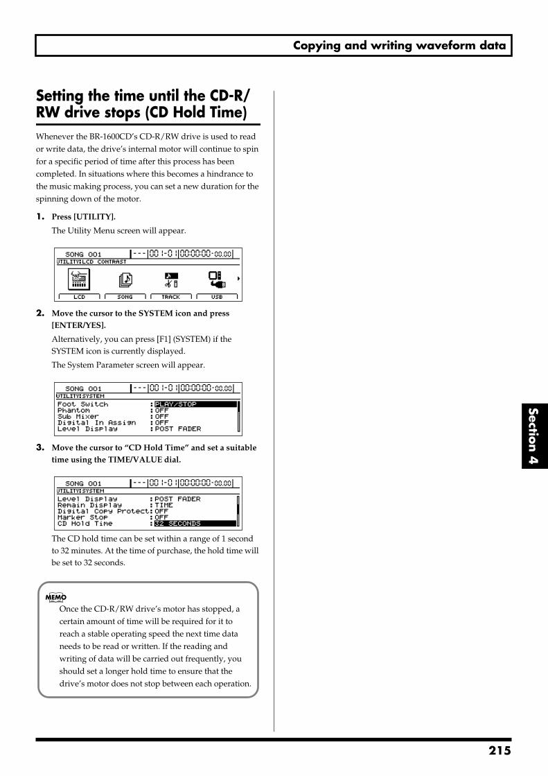
Copying and writing waveform data
Section 4
Setting the time until the CD-R/RW drive stops (CD Hold Time)Whenever the BR-1600CD’s CD-R/RW drive is used to read or write data, the drive’s internal motor will continue to spin for a specific period of time after this process has been completed. In situations where this becomes a hindrance to the music making process, you can set a new duration for the spinning down of the motor.
1. Press [UTILITY].
The Utility Menu screen will appear.fig.12-12d
2. Move the cursor to the SYSTEM icon and press [ENTER/YES].
Alternatively, you can press [F1] (SYSTEM) if the SYSTEM icon is currently displayed.
The System Parameter screen will appear.fig.10-03d
3. Move the cursor to “CD Hold Time” and set a suitable time using the TIME/VALUE dial.
fig.41-34d
The CD hold time can be set within a range of 1 second to 32 minutes. At the time of purchase, the hold time will be set to 32 seconds.
Once the CD-R/RW drive’s motor has stopped, a certain amount of time will be required for it to reach a stable operating speed the next time data needs to be read or written. If the reading and writing of data will be carried out frequently, you should set a longer hold time to ensure that the drive’s motor does not stop between each operation.
215
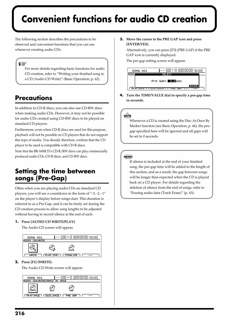
2
Convenient functions for audio CD creation
The following section describes the precautions to be observed and convenient functions that you can use whenever creating audio CDs.
PrecautionsIn addition to CD-R discs, you can also use CD-RW discs when making audio CDs. However, it may not be possible for audio CDs created using CD-RW discs to be played on standard CD players.
Furthermore, even when CD-R discs are used for this purpose, playback will not be possible on CD players that do not support this type of media. You should, therefore, confirm that the CD player to be used is compatible with CD-R discs.
Note that the BR-1600CD’s CD-R/RW drive can play commercially produced audio CDs, CD-R discs, and CD-RW discs.
Setting the time between songs (Pre-Gap)Often when you are playing audio CDs on standard CD players, you will see a countdown in the form of “-3, -2, -1” on the player’s display before songs start. This duration is referred to as a Pre-Gap, and it can be freely set during the CD creation process to allow song lengths to be adjusted without having to record silence at the end of each.
1. Press [AUDIO CD WRITE/PLAY].
The Audio CD screen will appear.fig.40-01d
2. Press [F1] (WRITE).
The Audio CD Write screen will appear.fig.40-02d
3. Move the cursor to the PRE GAP icon and press [ENTER/YES].
Alternatively, you can press [F3] (PRE GAP) if the PRE GAP icon is currently displayed.
The pre-gap setting screen will appear.fig.40-03d
4. Turn the TIME/VALUE dial to specify a pre-gap time in seconds.
For more details regarding basic functions for audio CD creation, refer to “Writing your finished song to a CD (Audio CD Write)” (Basic Operation; p. 62).
Whenever a CD is created using the Disc At Once By Marker function (see Basic Operation; p. 66), the pre-gap specified here will be ignored and all gaps will be set to 0 seconds.
If silence is included at the end of your finished song, the pre-gap time will be added to the length of this section, and as a result, the gap between songs will be longer than expected when the CD is played back on a CD player. For details regarding the deletion of silence from the end of songs, refer to “Erasing audio data (Track Erase)” (p. 63).
16
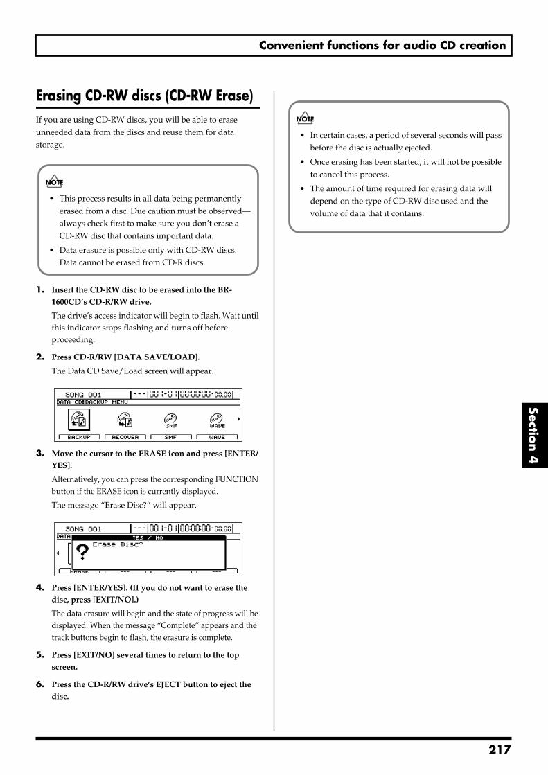
Convenient functions for audio CD creation
Section 4
Erasing CD-RW discs (CD-RW Erase)If you are using CD-RW discs, you will be able to erase unneeded data from the discs and reuse them for data storage.
1. Insert the CD-RW disc to be erased into the BR-1600CD’s CD-R/RW drive.
The drive’s access indicator will begin to flash. Wait until this indicator stops flashing and turns off before proceeding.
2. Press CD-R/RW [DATA SAVE/LOAD].
The Data CD Save/Load screen will appear.fig.40-04d
3. Move the cursor to the ERASE icon and press [ENTER/YES].
Alternatively, you can press the corresponding FUNCTION button if the ERASE icon is currently displayed.
The message “Erase Disc?” will appear.fig.40-05d
4. Press [ENTER/YES]. (If you do not want to erase the disc, press [EXIT/NO].)
The data erasure will begin and the state of progress will be displayed. When the message “Complete” appears and the track buttons begin to flash, the erasure is complete.
5. Press [EXIT/NO] several times to return to the top screen.
6. Press the CD-R/RW drive’s EJECT button to eject the disc.
• This process results in all data being permanently erased from a disc. Due caution must be observed—always check first to make sure you don’t erase a CD-RW disc that contains important data.
• Data erasure is possible only with CD-RW discs. Data cannot be erased from CD-R discs.
• In certain cases, a period of several seconds will pass before the disc is actually ejected.
• Once erasing has been started, it will not be possible to cancel this process.
• The amount of time required for erasing data will depend on the type of CD-RW disc used and the volume of data that it contains.
217
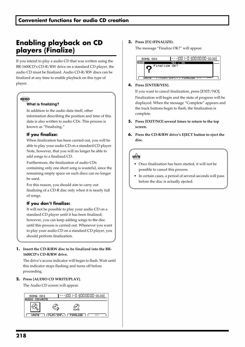
Convenient functions for audio CD creation
Enabling playback on CD players (Finalize)If you intend to play a audio CD that was written using the BR-1600CD’s CD-R/RW drive on a standard CD player, the audio CD must be finalized. Audio CD-R/RW discs can be finalized at any time to enable playback on this type of player.
1. Insert the CD-R/RW disc to be finalized into the BR-1600CD’s CD-R/RW drive.
The drive’s access indicator will begin to flash. Wait until this indicator stops flashing and turns off before proceeding.
2. Press [AUDIO CD WRITE/PLAY].
The Audio CD screen will appear.fig.40-01d
3. Press [F3] (FINALIZE).
The message “Finalize OK?” will appear.fig.40-07d
4. Press [ENTER/YES].
If you want to cancel finalization, press [EXIT/NO].
Finalization will begin and the state of progress will be displayed. When the message “Complete” appears and the track buttons begin to flash, the finalization is complete.
5. Press [EXIT/NO] several times to return to the top screen.
6. Press the CD-R/RW drive’s EJECT button to eject the disc.
What is finalizing?
In addition to the audio data itself, other information describing the position and time of this data is also written to audio CDs. This process is known as “Finalizing.”
If you finalize:When finalization has been carried out, you will be able to play your audio CD on a standard CD player. Note, however, that you will no longer be able to add songs to a finalized CD.
Furthermore, the finalization of audio CDs containing only one short song is wasteful, since the remaining empty space on such discs can no longer be used.
For this reason, you should aim to carry out finalizing of a CD-R disc only when it is nearly full of songs.
If you don’t finalize:It will not be possible to play your audio CD on a standard CD player until it has been finalized; however, you can keep adding songs to the disc until this process is carried out. Whenever you want to play your audio CD on a standard CD player, you should perform finalization.
• Once finalization has been started, it will not be possible to cancel this process.
• In certain cases, a period of several seconds will pass before the disc is actually ejected.
218
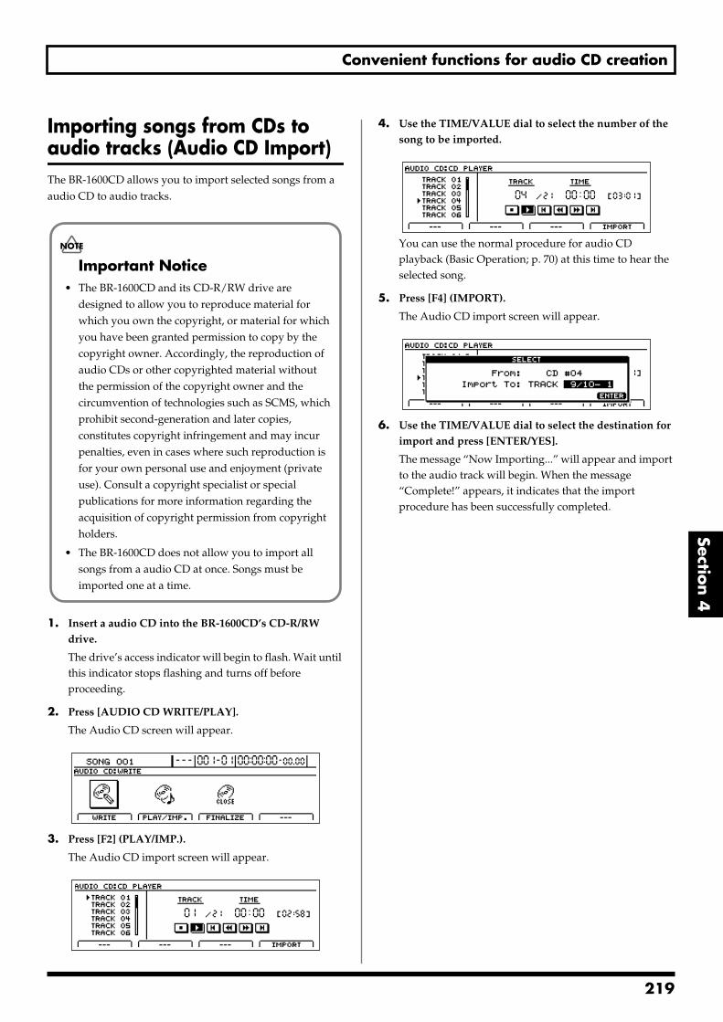
Convenient functions for audio CD creation
Section 4
Importing songs from CDs to audio tracks (Audio CD Import)The BR-1600CD allows you to import selected songs from a audio CD to audio tracks.
1. Insert a audio CD into the BR-1600CD’s CD-R/RW drive.
The drive’s access indicator will begin to flash. Wait until this indicator stops flashing and turns off before proceeding.
2. Press [AUDIO CD WRITE/PLAY].
The Audio CD screen will appear.fig.40-01d
3. Press [F2] (PLAY/IMP.).
The Audio CD import screen will appear.fig.40-09d
4. Use the TIME/VALUE dial to select the number of the song to be imported.
fig.40-09ad
You can use the normal procedure for audio CD playback (Basic Operation; p. 70) at this time to hear the selected song.
5. Press [F4] (IMPORT).
The Audio CD import screen will appear.fig.40-09bd
6. Use the TIME/VALUE dial to select the destination for import and press [ENTER/YES].
The message “Now Importing...” will appear and import to the audio track will begin. When the message “Complete!” appears, it indicates that the import procedure has been successfully completed.
Important Notice• The BR-1600CD and its CD-R/RW drive are
designed to allow you to reproduce material for which you own the copyright, or material for which you have been granted permission to copy by the copyright owner. Accordingly, the reproduction of audio CDs or other copyrighted material without the permission of the copyright owner and the circumvention of technologies such as SCMS, which prohibit second-generation and later copies, constitutes copyright infringement and may incur penalties, even in cases where such reproduction is for your own personal use and enjoyment (private use). Consult a copyright specialist or special publications for more information regarding the acquisition of copyright permission from copyright holders.
• The BR-1600CD does not allow you to import all songs from a audio CD at once. Songs must be imported one at a time.
219

MEMO
220
Section 5 Using MIDI
Section 5Using MIDI
221
2
MIDI fundamentals
By using MIDI to connect the BR-1600CD to other MIDI-capable devices, you can perform the following:
Play rhythm guide performances on external MIDI sound module
Synchronize with external MIDI sequencers and rhythm machines
Control MMC-compatible devices from the BR-1600CD
Control track volumes automatically via MIDI (MIDI Fader)
Input drum and bass patterns using an external keyboard (MIDI Recording)
This section provides a basic description of MIDI and explains the various ways it can be used.
What is MIDI?MIDI stands for “Musical Instrument Digital Interface.” MIDI is a global standard devised so that performance data, program change data, and other similar information could be exchanged among electronic musical instruments and computers. If a device is MIDI compatible, it will be able to exchange performance data with other MIDI compatible devices, even if they are of a different type or brand.
MIDI connectorsMIDI messages (i.e., the data handled by MIDI) are exchanged using the following three types of MIDI port.
MIDI IN:This connector accepts the MIDI messages arriving from other MIDI devices.
MIDI OUT:All the MIDI messages from the BR-1600CD are sent out from this connector.
MIDI THRU:This connector re-transmits all the MIDI messages that arrive at the MIDI IN connector.
The BR-1600CD is equipped with a MIDI IN and MIDI OUT port, but not with a MIDI THRU port.
MIDI channelsThe MIDI standard allows data to be exchanged among multiple MIDI-compatible devices using a single MIDI cable, and this is made possible by what are known as MIDI channels.
In simple terms, a MIDI channel is quite similar to a TV channel. For example, you can change TV channels to watch programs from a variety of broadcasters. In this type of situation, information is communicated only when the channel on the transmitting end matches the channel on the receiving end.
Likewise, with MIDI as well, if the transmitting device is (for example) set to MIDI channel 1, MIDI messages will be received only if the MIDI channel on the receiving end is also set to 1.
MIDI Implementation ChartsMIDI makes it possible for a vast range of electronic musical devices to communicate with each other. However, this does not mean that every MIDI device can handle every single type of MIDI message. In reality, two MIDI-compatible devices can only exchange the MIDI messages that are supported by both.
The user’s manual for any MIDI-compatible device will contain a MIDI Implementation Chart, and this chart allows you to quickly find out which MIDI messages the device in question can transmit and receive.
When two MIDI devices are to be used together, you should compare their MIDI implementation charts to make sure that exchange of the required MIDI messages will be possible.
For more detailed information regarding the BR-1600CD’s MIDI characteristics, refer to “MIDI Implementation” (p. 288).
22
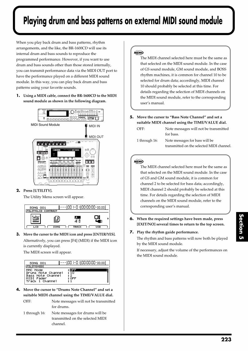
Playing drum and bass patterns on external MIDI sound module
Section 5
When you play back drum and bass patterns, rhythm arrangements, and the like, the BR-1600CD will use its internal drum and bass sounds to reproduce the programmed performance. However, if you want to use drum and bass sounds other than those stored internally, you can transmit performance data via the MIDI OUT port to have the performance played on a different MIDI sound module. In this way, you can play back drum and bass patterns using your favorite sounds.
1. Using a MIDI cable, connect the BR-1600CD to the MIDI sound module as shown in the following diagram.
fig.50-01
2. Press [UTILITY].
The Utility Menu screen will appear.fig.12-12d
3. Move the cursor to the MIDI icon and press [ENTER/YES].
Alternatively, you can press [F4] (MIDI) if the MIDI icon is currently displayed.
The MIDI screen will appear.fig.50-03d
4. Move the cursor to “Drums Note Channel” and set a suitable MIDI channel using the TIME/VALUE dial.
OFF: Note messages will not be transmitted for drums.
1 through 16: Note messages for drums will be transmitted on the selected MIDI channel.
5. Move the cursor to “Bass Note Channel” and set a suitable MIDI channel using the TIME/VALUE dial.
OFF: Note messages will not be transmitted for bass.
1 through 16: Note messages for bass will be transmitted on the selected MIDI channel.
6. When the required settings have been made, press [EXIT/NO] several times to return to the top screen.
7. Play the rhythm guide performance.
The rhythm and bass patterns will now both be played by the MIDI sound module.
If necessary, adjust the volume of the performances on the MIDI sound module.
MIDI Sound Module
MIDI OUT
MIDI IN
The MIDI channel selected here must be the same as that selected on the MIDI sound module. In the case of GS sound module, GM sound module, and BOSS rhythm machines, it is common for channel 10 to be selected for drum data; accordingly, MIDI channel 10 should probably be selected at this time. For details regarding the selection of MIDI channels on the MIDI sound module, refer to the corresponding user’s manual.
The MIDI channel selected here must be the same as that selected on the MIDI sound module. In the case of GS and GM sound module, it is common for channel 2 to be selected for bass data; accordingly, MIDI channel 2 should probably be selected at this time. For details regarding the selection of MIDI channels on the MIDI sound module, refer to the corresponding user’s manual.
223
Playing drum and bass patterns on external MIDI sound module
Drum sounds and note numbersThe correspondence between drum sounds and note numbers is as shown below.
If the drum sounds of your MIDI sound generating device are not mapped as shown above, you should change the sounds assigned to the various note numbers.
Refer to the user’s manual for the MIDI sound module for details on how this is done.
Drum name Note number
Kick 1 C 2 (36)
Snare 1 D 2 (38)
Closed hi-hat F#2 (42)
Open hi-hat A#2 (46)
Crash cymbal C#3 (49)
Ride cymbal D#3 (51)
Tom 1 F 2 (41)
Tom 2 A 2 (45)
Tom 3 C3 (48)
Tom 4 D 3 (50)
Stick G 1 (31)
Cow bell G#3 (56)
Kick 2 B 1 (35)
Snare 2 E 2 (40)
Metronome (click) A 1 (33)
Metronome (bell) A#1 (34)
Claves D#5 (75)
Hi-Q D#1 (27)
224
Synchronizing external MIDI sequencers and rhythm machines
Section 5
You can use the BR-1600CD’s tempo and time position as the master tempo and master time position so that external MIDI sequencers and rhythm machines can be synchronized with its playback (Master Sync). The following three synchronization methods are available.
A MIDI sequencer or rhythm machine can be synchronized to the rhythm guide’s tempo using the BR-1600CD’s MIDI timing clock.
A MIDI sequencer can be synchronized to the playback time using MTC.
The tempo variations programmed into a MIDI sequencer or rhythm machine can be recorded as a sync track on the BR-1600CD, and the sequencer or rhythm machine can then be played back using the recorded tempos.
Even in the case of MIDI sequencers that are compatible with neither MTC nor MMC, synchronization to the rhythm guide will be possible using the MIDI timing clock if Song Position Pointers are supported. Note, however, that a tempo map must be created for the rhythm guide in advance. For more detailed information, refer to “Setting tempos for individual measures (Tempo Map)” (p. 198).
Synchronizing a MIDI device to the rhythm’s tempo using the MIDI timing clockThis is the simplest of the three synchronization methods, and it can be used to synchronize the majority of MIDI sequencers and rhythm machines.
In this case, the MIDI timing clock is used as the synchronization master. Specifically, the MIDI timing clock is a signal that is transmitted six times per sixteenth note in accordance with the current tempo. It can be used to notify MIDI sequencers and rhythm machines of the time elapsed since the start of the song so that these external devices can be synchronized.
As the majority of MIDI sequencers and rhythm machines sold today support MIDI timing clock signals, this method will probably provide the simplest means of achieving synchronization.
1. Using a MIDI cable, connect the BR-1600CD to the MIDI sound module as shown in the following diagram.
fig.50-04
2. Press [UTILITY].
The Utility Menu screen will appear.fig.12-12d
3. Move the cursor to the SYNC icon and press [ENTER/YES].
Alternatively, you can press [F2] (SYNC) if the SYNC icon is currently displayed.
For more information regarding MIDI sequencer usage methods, refer to the corresponding user’s manual. Refer to p. 231 for details regarding MMC.
The BR-1600CD does not support operation in slave mode. In other words, it will not be possible to synchronize the BR-1600CD to the tempo and time position of an external MIDI sequencer or rhythm machine.
BR-1600CD Externalrhythm machine
MIDI INMIDI OUT
Master
Synchronization will be possible
BR-1600CD Externalrhythm machine
MIDI OUTMIDI IN
Slave
Synchronization will not be possible
Rhythm machine orMIDI sequencer
MIDI OUT
MIDI IN
225
Synchronizing external MIDI sequencers and rhythm machines
The synchronization setting screen will appear.fig.50-06d
4. Move the cursor to “Sync Generator” and select “MIDI CLOCK” using the TIME/VALUE dial.
Sync Generator:This parameter sets the type of synchronization signal that will be output via the MIDI OUT port. When you intend to perform synchronized operation of an external MIDI device using a synchronization signal, ensure that one of the following types of signal is selected for transmission.
OFF:
No synchronization signal will be transmitted.
MTC:
MTC (MIDI Time Code) will be transmitted.
MIDI CLOCK:
MIDI timing clock signals will be transmitted based on the rhythm tempo.
5. Press [EXIT/NO] several times to return to the top screen.
6. Start playback on the BR-1600CD.
As playback starts, the MIDI sequencer will also start to play in sync.
Synchronizing a MIDI sequencer to the playback time using MTCThe term MIDI Time Code (MTC) refers to a type of time-synchronization message that is output every frame in order to allow MIDI sequencers to be synchronized. Since MTC is based on time and not tempo, it allows extremely precise synchronization to be achieved. Although this technique is most often used with video equipment and the like, a large number of MIDI sequencers are also MTC compatible.
1. First of all, set up the external MIDI sequencer to operate based on received MTC signals.
For more information regarding setting methods for the MIDI sequencer, refer to its user’s manual.
2. Using a MIDI cable, connect the BR-1600CD to the MIDI sequencer as shown in the following diagram.
fig.50-07
3. Press [UTILITY].
The Utility Menu screen will appear.fig.12-12d
4. Move the cursor to the SYNC icon and press [ENTER/YES].
Alternatively, you can press [F2] (SYNC) if the SYNC icon is currently displayed.
The Sync Parameter screen will appear.
MIDI sequencer
MIDI OUT
MIDI IN
226
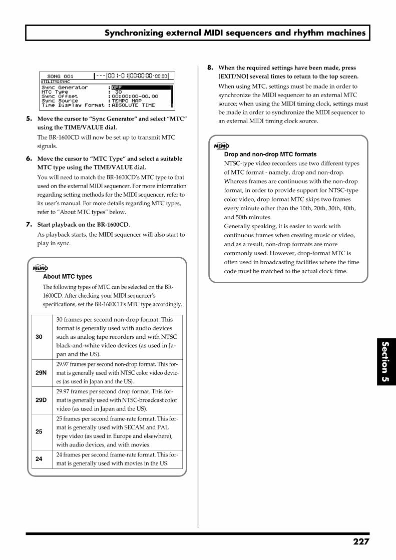
Synchronizing external MIDI sequencers and rhythm machines
Section 5
fig.50-09d
5. Move the cursor to “Sync Generator” and select “MTC” using the TIME/VALUE dial.
The BR-1600CD will now be set up to transmit MTC signals.
6. Move the cursor to “MTC Type” and select a suitable MTC type using the TIME/VALUE dial.
You will need to match the BR-1600CD’s MTC type to that used on the external MIDI sequencer. For more information regarding setting methods for the MIDI sequencer, refer to its user’s manual. For more details regarding MTC types, refer to “About MTC types” below.
7. Start playback on the BR-1600CD.
As playback starts, the MIDI sequencer will also start to play in sync.
8. When the required settings have been made, press [EXIT/NO] several times to return to the top screen.
When using MTC, settings must be made in order to synchronize the MIDI sequencer to an external MTC source; when using the MIDI timing clock, settings must be made in order to synchronize the MIDI sequencer to an external MIDI timing clock source.
About MTC types
The following types of MTC can be selected on the BR-1600CD. After checking your MIDI sequencer’s specifications, set the BR-1600CD’s MTC type accordingly.
30
30 frames per second non-drop format. This format is generally used with audio devices such as analog tape recorders and with NTSC black-and-white video devices (as used in Ja-pan and the US).
29N29.97 frames per second non-drop format. This for-mat is generally used with NTSC color video devic-es (as used in Japan and the US).
29D29.97 frames per second drop format. This for-mat is generally used with NTSC-broadcast color video (as used in Japan and the US).
25
25 frames per second frame-rate format. This for-mat is generally used with SECAM and PAL type video (as used in Europe and elsewhere), with audio devices, and with movies.
2424 frames per second frame-rate format. This for-mat is generally used with movies in the US.
Drop and non-drop MTC formats
NTSC-type video recorders use two different types of MTC format - namely, drop and non-drop. Whereas frames are continuous with the non-drop format, in order to provide support for NTSC-type color video, drop format MTC skips two frames every minute other than the 10th, 20th, 30th, 40th, and 50th minutes. Generally speaking, it is easier to work with continuous frames when creating music or video, and as a result, non-drop formats are more commonly used. However, drop-format MTC is often used in broadcasting facilities where the time code must be matched to the actual clock time.
227
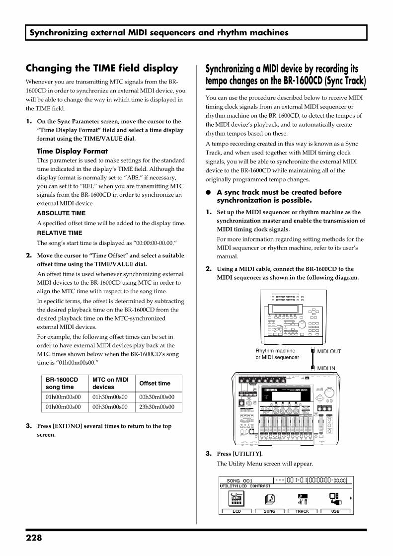
Synchronizing external MIDI sequencers and rhythm machines
Changing the TIME field displayWhenever you are transmitting MTC signals from the BR-1600CD in order to synchronize an external MIDI device, you will be able to change the way in which time is displayed in the TIME field.
1. On the Sync Parameter screen, move the cursor to the “Time Display Format” field and select a time display format using the TIME/VALUE dial.
Time Display FormatThis parameter is used to make settings for the standard time indicated in the display’s TIME field. Although the display format is normally set to “ABS,” if necessary, you can set it to “REL” when you are transmitting MTC signals from the BR-1600CD in order to synchronize an external MIDI device.
ABSOLUTE TIME
A specified offset time will be added to the display time.
RELATIVE TIME
The song’s start time is displayed as “00:00:00-00.00.”
2. Move the cursor to “Time Offset” and select a suitable offset time using the TIME/VALUE dial.
An offset time is used whenever synchronizing external MIDI devices to the BR-1600CD using MTC in order to align the MTC time with respect to the song time.
In specific terms, the offset is determined by subtracting the desired playback time on the BR-1600CD from the desired playback time on the MTC-synchronized external MIDI devices.
For example, the following offset times can be set in order to have external MIDI devices play back at the MTC times shown below when the BR-1600CD’s song time is “01h00m00s00.”
3. Press [EXIT/NO] several times to return to the top screen.
Synchronizing a MIDI device by recording its tempo changes on the BR-1600CD (Sync Track)You can use the procedure described below to receive MIDI timing clock signals from an external MIDI sequencer or rhythm machine on the BR-1600CD, to detect the tempos of the MIDI device’s playback, and to automatically create rhythm tempos based on these.
A tempo recording created in this way is known as a Sync Track, and when used together with MIDI timing clock signals, you will be able to synchronize the external MIDI device to the BR-1600CD while maintaining all of the originally programmed tempo changes.
A sync track must be created before synchronization is possible.
1. Set up the MIDI sequencer or rhythm machine as the synchronization master and enable the transmission of MIDI timing clock signals.
For more information regarding setting methods for the MIDI sequencer or rhythm machine, refer to its user’s manual.
2. Using a MIDI cable, connect the BR-1600CD to the MIDI sequencer as shown in the following diagram.
fig.50-10
3. Press [UTILITY].
The Utility Menu screen will appear.fig.12-12d
BR-1600CD song time
MTC on MIDI devices
Offset time
01h00m00s00 01h30m00s00 00h30m00s00
01h00m00s00 00h30m00s00 23h30m00s00
Rhythm machineor MIDI sequencer
MIDI IN
MIDI OUT
228
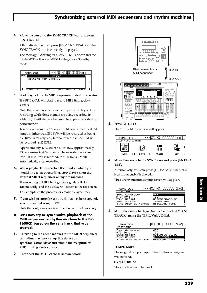
Synchronizing external MIDI sequencers and rhythm machines
Section 5
4. Move the cursor to the SYNC TRACK icon and press [ENTER/YES].
Alternatively, you can press [F3] (SYNC TRACK) if the SYNC TRACK icon is currently displayed.
The message “Waiting for Clock...” will appear and the BR-1600CD will enter MIDI Timing Clock Standby mode.
fig.50-12d
5. Start playback on the MIDI sequencer or rhythm machine.
The BR-1600CD will start to record MIDI timing clock signals.
Note that it will not be possible to perform playback or recording while these signals are being recorded. In addition, it will also not be possible to play back rhythm performances.
Tempos in a range of 25 to 250 BPM can be recorded. All tempos higher than 250 BPM will be recorded as being 250 BPM; similarly, any tempo lower than 25 BPM will be recorded as 25 BPM.
Approximately 4,000 eighth notes (i.e., approximately 500 measures in 4/4-time) can be recorded in a sync track. If this limit is reached, the BR-1600CD will automatically stop recording.
6. When playback has reached the point at which you would like to stop recording, stop playback on the external MIDI sequencer or rhythm machine.
The recording of MIDI timing clock signals will stop automatically, and the display will return to the top screen.
This completes the process for creating a sync track.
7. If you wish to store the sync track that has been created, save the current song (p. 72).
Note that only one sync track can be recorded per song.
Let’s now try to synchronize playback of the MIDI sequencer or rhythm machine to the BR-1600CD based on the sync track that was created.
1. Referring to the user’s manual for the MIDI sequencer or rhythm machine, set up this device as a synchronization slave and enable the reception of MIDI timing clock signals.
2. Reconnect the MIDI cable as shown below.
fig.50-13
3. Press [UTILITY].
The Utility Menu screen will appear.fig.12-12d
4. Move the cursor to the SYNC icon and press [ENTER/YES].
Alternatively, you can press [F2] (SYNC) if the SYNC icon is currently displayed.
The synchronization setting screen will appear.fig.50-15d
5. Move the cursor to “Sync Source” and select “SYNC TRACK” using the TIME/VALUE dial.
fig.50-16d
TEMPO MAP:
The original tempo map for the rhythm arrangement will be used.
SYNC TRACK:
The sync track will be used.
Rhythm machine or MIDI sequencer
MIDI OUT
MIDI IN
229
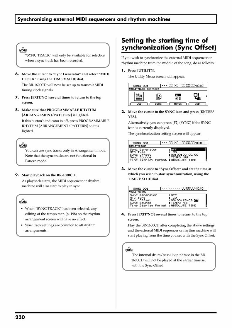
Synchronizing external MIDI sequencers and rhythm machines
6. Move the cursor to “Sync Generator” and select “MIDI CLOCK” using the TIME/VALUE dial.
The BR-1600CD will now be set up to transmit MIDI timing clock signals.
7. Press [EXIT/NO] several times to return to the top screen.
8. Make sure that PROGRAMMABLE RHYTHM [ARRANGEMENT/PATTERN] is lighted.
If this button’s indicator is off, press PROGRAMMABLE RHYTHM [ARRANGEMENT/PATTERN] so it is lighted.
9. Start playback on the BR-1600CD.
As playback starts, the MIDI sequencer or rhythm machine will also start to play in sync.
Setting the starting time of synchronization (Sync Offset)If you wish to synchronize the external MIDI sequencer or rhythm machine from the middle of the song, do as follows:
1. Press [UTILITY].
The Utility Menu screen will appear.fig.12-12d
2. Move the cursor to the SYNC icon and press [ENTER/YES].
Alternatively, you can press [F2] (SYNC) if the SYNC icon is currently displayed.
The synchronization setting screen will appear.fig.50-06d
3. Move the cursor to “Sync Offset” and set the time at which you wish to start synchronization, using the TIME/VALUE dial.
fig.50-100d
4. Press [EXIT/NO] several times to return to the top screen.
Play the BR-1600CD after completing the above settings, and the external MIDI sequencer or rhythm machine will start playing from the time you set with the Sync Offset.
“SYNC TRACK” will only be available for selection when a sync track has been recorded.
You can use sync tracks only in Arrangement mode. Note that the sync tracks are not functional in Pattern mode.
• When “SYNC TRACK” has been selected, any editing of the tempo map (p. 198) on the rhythm arrangement screen will have no effect.
• Sync track settings are common to all rhythm arrangements.
The internal drum/bass/loop phrase in the BR-1600CD will not be played at the earlier time set with the Sync Offset.
230
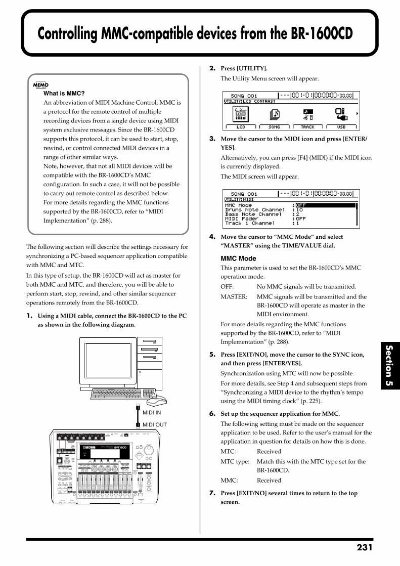
Controlling MMC-compatible devices from the BR-1600CD
Section 5
The following section will describe the settings necessary for synchronizing a PC-based sequencer application compatible with MMC and MTC.
In this type of setup, the BR-1600CD will act as master for both MMC and MTC, and therefore, you will be able to perform start, stop, rewind, and other similar sequencer operations remotely from the BR-1600CD.
1. Using a MIDI cable, connect the BR-1600CD to the PC as shown in the following diagram.
fig.50-17
2. Press [UTILITY].
The Utility Menu screen will appear.fig.12-12d
3. Move the cursor to the MIDI icon and press [ENTER/YES].
Alternatively, you can press [F4] (MIDI) if the MIDI icon is currently displayed.
The MIDI screen will appear.fig.50-19d
4. Move the cursor to “MMC Mode” and select “MASTER” using the TIME/VALUE dial.
MMC ModeThis parameter is used to set the BR-1600CD’s MMC operation mode.
OFF: No MMC signals will be transmitted.
MASTER: MMC signals will be transmitted and the BR-1600CD will operate as master in the MIDI environment.
For more details regarding the MMC functions supported by the BR-1600CD, refer to “MIDI Implementation” (p. 288).
5. Press [EXIT/NO], move the cursor to the SYNC icon, and then press [ENTER/YES].
Synchronization using MTC will now be possible.
For more details, see Step 4 and subsequent steps from “Synchronizing a MIDI device to the rhythm’s tempo using the MIDI timing clock” (p. 225).
6. Set up the sequencer application for MMC.
The following setting must be made on the sequencer application to be used. Refer to the user’s manual for the application in question for details on how this is done.
MTC: Received
MTC type: Match this with the MTC type set for the BR-1600CD.
MMC: Received
7. Press [EXIT/NO] several times to return to the top screen.
What is MMC?
An abbreviation of MIDI Machine Control, MMC is a protocol for the remote control of multiple recording devices from a single device using MIDI system exclusive messages. Since the BR-1600CD supports this protocol, it can be used to start, stop, rewind, or control connected MIDI devices in a range of other similar ways. Note, however, that not all MIDI devices will be compatible with the BR-1600CD’s MMC configuration. In such a case, it will not be possible to carry out remote control as described below. For more details regarding the MMC functions supported by the BR-1600CD, refer to “MIDI Implementation” (p. 288).
MIDI IN
MIDI OUT
231
2
Controlling track volumes via MIDI (MIDI Fader)
The BR-1600CD can both transmit and receive fader operations in the form of MIDI signals (MIDI Fader). And in addition to fader signals, expression pedal signals can also be transmitted and received in the same way. By using this function to record and playback fader and expression pedal operations on an external device such as a MIDI sequencer, you will be able to carry out remote control of BR-1600CD mix-downs and other procedures.
Signals can be transmitted and received for the following types of faders.
• Faders for Tracks 1 through 8 and 9/10 through 15/16
• The MASTER fader
• An expression pedal
Turning MIDI Fader on and offUse the following procedure to turn the transmission and reception of fader operations via MIDI on and off. At the time of purchase, MIDI Fader will be turned off, so you will need to turn this function on if you intend to use it.
1. Press [UTILITY].
The Utility Menu screen will appear.fig.12-12d
2. Move the cursor to the MIDI icon and press [ENTER/YES].
Alternatively, you can press [F4] (MIDI) if the MIDI icon is currently displayed.
The MIDI screen will appear.fig50-21d
3. Move the cursor to “MIDI Fader” and select “ON” using the TIME/VALUE dial.
Fader operation data will now be transmitted and received using controller number 7 (i.e., channel volume).
Operation signals for the INPUT SENS and INPUT LEVEL knobs cannot be communicated via MIDI.
The MIDI Fader on/off setting will be maintained when the BR-1600CD is turned off. Note, however, that if you fail to turn the BR-1600CD off in accordance with the correct shutdown procedure, this setting data will be lost.
32
Controlling track volumes via MIDI (MIDI Fader)
Section 5
Setting the MIDI channel for MIDI FaderAt the time of purchase, the following MIDI channels will be initially assigned to the BR-1600CD’s faders and expression pedal.
Tracks 1 through 8: Channels 1 through 8
Track 9/10: Channel 9
Track 11/12: Channel 11
Track 13/14: Channel 13
Track 15/16: Channel 15
MASTER fader Channel 16
Expression pedal OFF
Use the following procedure to change any of these MIDI channel settings.
1. Press [UTILITY].
The Utility Menu screen will appear.fig.12-12d
2. Move the cursor to the MIDI icon and press [ENTER/YES].
Alternatively, you can press [F4 (MIDI) if the MIDI icon is currently displayed.
The MIDI screen will appear.fig.50-23d
3. Move the cursor to one of the channel settings (i.e., “Track 1 Channel” through “Track 15&16 Channel,” “Master Fader Channel” and “EXP Pedal Channel”), and change the channel assignment using the TIME/VALUE dial.
OFF:
Fader operation data will not be communicated via MIDI.
1 through 16:
This channel will be used to transmit and receive fader operation data. If the same MIDI channel is set for a number of different faders, any fader operation data received on that channel will be used to operate all of the corresponding faders simultaneously.
Confirming the current fader positionsWhen fader operation data is received via MIDI, the setting for the corresponding fader will change while the actual fader remains in the same position, and as a result, the volume level indicated by the fader and the actual volume level will no longer match.
In such a case, you can use the following procedure to confirm the fader position and the actual volume level.
1. Press [UTILITY].
The Utility Menu screen will appear.fig.12-12d
2. Move the cursor to the FADER icon and press [ENTER/YES].
Alternatively, you can press [F1] (FADER) if the FADER icon is currently displayed.
A screen showing the various fader positions will appear.
fig.50-25d
: Position of the fader (i.e., the indicated volume)
: Actual fader setting (i.e., the actual volume level)
Whenever you physically move a fader, the actual fader setting will be aligned with the fader position, and this condition is indicated by “ ” in the fader display.
The MIDI channel setting will be maintained when the BR-1600CD is turned off. Note, however, that if you fail to turn the BR-1600CD off in accordance with the correct shutdown procedure, this setting data will be lost.
233
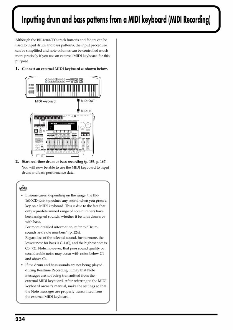
2
Inputting drum and bass patterns from a MIDI keyboard (MIDI Recording)
Although the BR-1600CD’s track buttons and faders can be used to input drum and bass patterns, the input procedure can be simplified and note volumes can be controlled much more precisely if you use an external MIDI keyboard for this purpose.
1. Connect an external MIDI keyboard as shown below.fig.50-26
2. Start real-time drum or bass recording (p. 153, p. 167).
You will now be able to use the MIDI keyboard to input drum and bass performance data.
MIDI keyboard
MIDI IN
MIDI OUT
• In some cases, depending on the range, the BR-1600CD won’t produce any sound when you press a key on a MIDI keyboard. This is due to the fact that only a predetermined range of note numbers have been assigned sounds, whether it be with drums or with bass.For more detailed information, refer to “Drum sounds and note numbers” (p. 224).Regardless of the selected sound, furthermore, the lowest note for bass is C-1 (0), and the highest note is C5 (72). Note, however, that poor sound quality or considerable noise may occur with notes below C1 and above C4.
• If the drum and bass sounds are not being played during Realtime Recording, it may that Note messages are not being transmitted from the external MIDI keyboard. After referring to the MIDI keyboard owner’s manual, make the settings so that the Note messages are properly transmitted from the external MIDI keyboard.
34
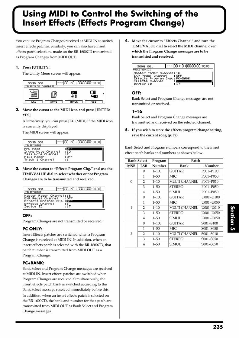
Using MIDI to Control the Switching of the Insert Effects (Effects Program Change)
Section 5
You can use Program Changes received at MIDI IN to switch insert effects patches. Similarly, you can also have insert effects patch selections made on the BR-1600CD transmitted as Program Changes from MIDI OUT.
1. Press [UTILITY].
The Utility Menu screen will appear.fig.12-12d
2. Move the cursor to the MIDI icon and press [ENTER/YES].
Alternatively, you can press [F4] (MIDI) if the MIDI icon is currently displayed.
The MIDI screen will appear.fig.50-21d
3. Move the cursor to “Effects Program Chg.” and use the TIME/VALUE dial to select whether or not Program Changes are to be transmitted and received.
fig.50-50d
OFF:Program Changes are not transmitted or received.
PC ONLY:Insert Effects patches are switched when a Program Change is received at MIDI IN. In addition, when an insert effects patch is selected with the BR-1600CD, that patch number is transmitted from MIDI OUT as a Program Change.
PC+BANK:Bank Select and Program Change messages are received at MIDI IN. Insert effects patches are switched when Program Changes are received. Simultaneously, the insert effects patch bank is switched according to the Bank Select message received immediately before this.
In addition, when an insert effects patch is selected on the BR-1600CD, the bank and number for that patch are transmitted from MIDI OUT as Bank Select and Program Change messages.
4. Move the cursor to “Effects Channel” and turn the TIME/VALUE dial to select the MIDI channel over which the Program Change messages are to be transmitted and received.
fig.50-60d
OFF:Bank Select and Program Change messages are not transmitted or received.
1–16Bank Select and Program Change messages are transmitted and received on the selected channel.
5. If you wish to store the effects program change setting, save the current song (p. 72).
Bank Select and Program numbers correspond to the insert effect patch banks and numbers as shown below.
Bank Select Program Number
PatchMSB LSB Bank Number
0
0 1–100 GUITAR P001–P1001 1–50 MIC P001–P0502 1–10 MULTI CHANNEL P001–P0103 1–50 STEREO P001–P0504 1–50 SIMUL P001–P050
1
0 1–100 GUITAR U001–U1001 1–50 MIC U001–U0502 1–10 MULTI CHANNEL U001–U0103 1–50 STEREO U001–U0504 1–50 SIMUL U001–U050
2
0 1–100 GUITAR S001–S1001 1–50 MIC S001–S0502 1–10 MULTI CHANNEL S001–S0103 1–50 STEREO S001–S0504 1–50 SIMUL S001–S050
235
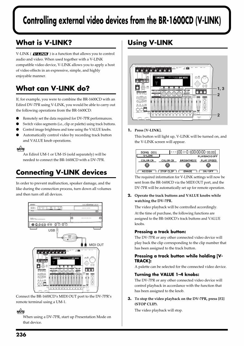
2
Controlling external video devices from the BR-1600CD (V-LINK)
What is V-LINK?V-LINK ( ) is a function that allows you to control audio and video. When used together with a V-LINK compatible video device, V-LINK allows you to apply a host of video effects in an expressive, simple, and highly enjoyable manner.
What can V-LINK do?If, for example, you were to combine the BR-1600CD with an Edirol DV-7PR using V-LINK, you would be able to carry out the following operations from the BR-1600CD:
Remotely set the data required for DV-7PR performances. Switch video segments (i.e., clip or palette) using track buttons. Control image brightness and tone using the VALUE knobs. Automatically control video by recording track button
and VALUE knob operations.
An Edirol UM-1 or UM-1S (sold separately) will be needed to connect the BR-1600CD with a DV-7PR.
Connecting V-LINK devicesIn order to prevent malfunction, speaker damage, and the like during the connection process, turn down all volumes and then turn off all devices.fig.51-01
Connect the BR-1600CD’s MIDI OUT port to the DV-7PR’s remote terminal using a UM-1.
When using a DV-7PR, start up Presentation Mode on that device.
Using V-LINKfig.51-02
1. Press [V-LINK].
This button will light up, V-LINK will be turned on, and the V-LINK screen will appear.
fig.51-03d
The required information for V-LINK settings will now be sent from the BR-1600CD via the MIDI OUT port, and the DV-7PR will be automatically set up for remote operation.
2. Operate the track buttons and VALUE knobs while watching the DV-7PR.
The video playback will be controlled accordingly.
At the time of purchase, the following functions are assigned to the BR-1600CD’s track buttons and VALUE knobs.
Pressing a track button:The DV-7PR or any other connected video device will play back the clip corresponding to the clip number that has been assigned to the track button.
Pressing a track button while holding [V-TRACK]:A palette can be selected for the connected video device.
Turning the VALUE 1–4 knobs:The DV-7PR or any other connected video device will control playback in accordance with the function that has been assigned to the knob.
3. To stop the video playback on the DV-7PR, press [F2] (STOP CLIP).
The video playback will stop.
MIDI OUT
USB
1, 3
2
2
36
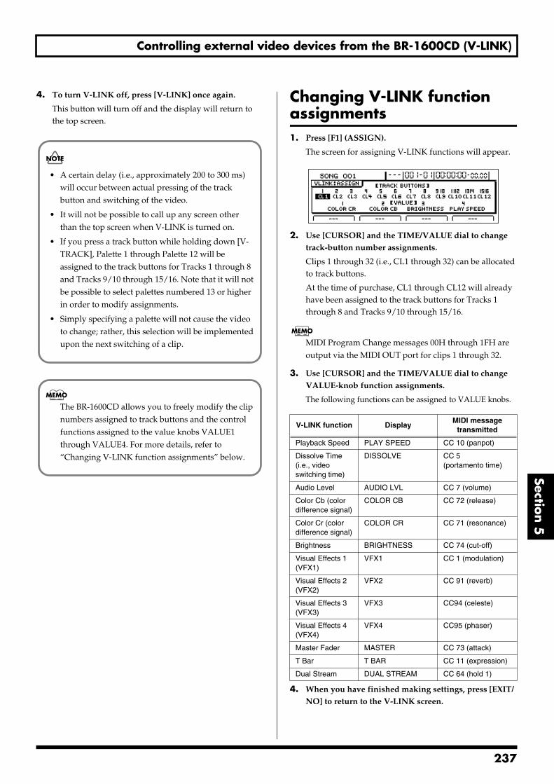
Controlling external video devices from the BR-1600CD (V-LINK)
Section 5
4. To turn V-LINK off, press [V-LINK] once again.
This button will turn off and the display will return to the top screen.
Changing V-LINK function assignments1. Press [F1] (ASSIGN).
The screen for assigning V-LINK functions will appear.fig.51-04d
2. Use [CURSOR] and the TIME/VALUE dial to change track-button number assignments.
Clips 1 through 32 (i.e., CL1 through 32) can be allocated to track buttons.
At the time of purchase, CL1 through CL12 will already have been assigned to the track buttons for Tracks 1 through 8 and Tracks 9/10 through 15/16.
MIDI Program Change messages 00H through 1FH are output via the MIDI OUT port for clips 1 through 32.
3. Use [CURSOR] and the TIME/VALUE dial to change VALUE-knob function assignments.
The following functions can be assigned to VALUE knobs.
4. When you have finished making settings, press [EXIT/NO] to return to the V-LINK screen.
• A certain delay (i.e., approximately 200 to 300 ms) will occur between actual pressing of the track button and switching of the video.
• It will not be possible to call up any screen other than the top screen when V-LINK is turned on.
• If you press a track button while holding down [V-TRACK], Palette 1 through Palette 12 will be assigned to the track buttons for Tracks 1 through 8 and Tracks 9/10 through 15/16. Note that it will not be possible to select palettes numbered 13 or higher in order to modify assignments.
• Simply specifying a palette will not cause the video to change; rather, this selection will be implemented upon the next switching of a clip.
The BR-1600CD allows you to freely modify the clip numbers assigned to track buttons and the control functions assigned to the value knobs VALUE1 through VALUE4. For more details, refer to “Changing V-LINK function assignments” below.
V-LINK function DisplayMIDI message
transmitted
Playback Speed PLAY SPEED CC 10 (panpot)
Dissolve Time(i.e., video switching time)
DISSOLVE CC 5(portamento time)
Audio Level AUDIO LVL CC 7 (volume)
Color Cb (color difference signal)
COLOR CB CC 72 (release)
Color Cr (color difference signal)
COLOR CR CC 71 (resonance)
Brightness BRIGHTNESS CC 74 (cut-off)
Visual Effects 1 (VFX1)
VFX1 CC 1 (modulation)
Visual Effects 2 (VFX2)
VFX2 CC 91 (reverb)
Visual Effects 3 (VFX3)
VFX3 CC94 (celeste)
Visual Effects 4 (VFX4)
VFX4 CC95 (phaser)
Master Fader MASTER CC 73 (attack)
T Bar T BAR CC 11 (expression)
Dual Stream DUAL STREAM CC 64 (hold 1)
237
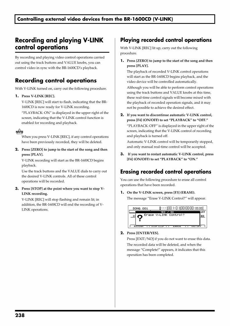
Controlling external video devices from the BR-1600CD (V-LINK)
Recording and playing V-LINK control operationsBy recording and playing video control operations carried out using the track buttons and VALUE knobs, you can control video in sync with the BR-1600CD’s playback.
Recording control operationsWith V-LINK turned on, carry out the following procedure.
1. Press V-LINK [REC].
V-LINK [REC] will start to flash, indicating that the BR-1600CD is now ready for V-LINK recording.
“PLAYBACK: ON” is displayed in the upper right of the screen, indicating that the V-LINK control function is enabled for recording and playback.
When you press V-LINK [REC], if any control operations have been previously recorded, they will be deleted.
2. Press [ZERO] to jump to the start of the song and then press [PLAY].
V-LINK recording will start as the BR-1600CD begins playback.
Use the track buttons and the VALUE dials to carry out the desired V-LINK controls. All of these control operations will be recorded.
3. Press [STOP] at the point where you want to stop V-LINK recording.
V-LINK [REC] will stop flashing and remain lit; in addition, the BR-1600CD will end the recording of V-LINK operations.
Playing recorded control operationsWith V-LINK [REC] lit up, carry out the following procedure.
1. Press [ZERO] to jump to the start of the song and then press [PLAY].
The playback of recorded V-LINK control operations will start as the BR-1600CD begins playback, and the video device will be controlled automatically.
Although you will be able to perform control operations using the track buttons and VALUE knobs at this time, these real-time control signals will become mixed with the playback of recorded operation signals, and it may not be possible to achieve the desired effect.
2. If you want to discontinue automatic V-LINK control, press [F4] (ON/OFF) to set “PLAYBACK” to “OFF.”
“PLAYBACK: OFF” is displayed in the upper right of the screen, indicating that the V-LINK control of recording and playback is turned off.
Automatic V-LINK control will be temporarily stopped, and only manual real-time control will be accepted.
3. If you want to restart automatic V-LINK control, press [F4] (ON/OFF) to set “PLAYBACK” to “ON.”
Erasing recorded control operationsYou can use the following procedure to erase all control operations that have been recorded.
1. On the V-LINK screen, press [F3] (ERASE).
The message “Erase V-LINK Control?” will appear.fig50-05d
2. Press [ENTER/YES].
Press [EXIT/NO] if you do not want to erase this data.
The recorded data will be deleted, and when the message “Complete!” appears, it indicates that this operation has been completed.
238
Section 6 Using USB
Section 6Using USB
239
2
Before Using USB (Overview)
The BR-1600CD is equipped with a USB connector, which allows you to connect the BR-1600CD directly to a computer, making it easy to back up your important song data and exchange files between the BR-1600CD and the computer.
USB, short for “Universal Serial Bus,” is a type of interface for connecting computers with a variety of peripheral devices.
Using USB allows you to connect different peripherals using a single USB cable, and also provides rapid data transmission.
What’s more, you can connect and disconnect peripherals with the power on, and the computer can automatically recognize when devices are connected (you may need to make settings when connecting certain devices).
Important When you connect the BR-1600CD to your PC using a
USB cable, all folders and files on the BR-1600CD’s hard disk will be displayed on the PC monitor, and you will be able to freely modify, delete, or add to these files via USB. In addition, you will be able to initialize the BR-1600CD’s hard disk remotely using the PC.Note, however, that if files and folders are modified, deleted, or added using the PC, or if the hard disk is initialized, the BR-1600CD may no longer be able to function properly, and important data could be lost. It is crucial, therefore, that no operations other than those described below be carried out using USB. Furthermore, BOSS/Roland will accept no responsibility for the incorrect operation of the BR-1600CD or for the loss of data resulting from the failure to observe this precaution.
Do not perform the following actions when switching to USB mode or transmitting data. These operations may result in your computer not responding to the data. Data on memory cards may also be corrupted.Do not:
• Disconnect the USB cable
• Put the computer in suspended (standby) mode or hibernation, restart, or quit
• Turn off the BR-1600CD’s power
Operations that can be performed via USBOn the BR-1600CD, USB is used for the following tasks:
Backing up the BR-1600CD’s data
Reading backup data back into the BR-1600CD from the PC (Recover)
Saving BR-1600CD track data in WAV/AIFF format (WAV/AIFF Export)
Loading WAV/AIFF files in BR-1600CD tracks (WAV/AIFF Import)
Realtime audio signals and MIDI messages cannot be handled via the BR-1600CD’s USB connector.
Compatible OS
Windows:Windows Me/2000/XP
Macintosh:Mac OS 9.1.x/9.2.x
Mac OS X
Driver:The BR-1600CD uses a standard DRIVER that is found on OS. The DRIVER will be installed automatically once connected with Computer via USB.
Precautions when using Windows XP or Windows 2000
If using Windows XP/2000, log on to Windows as one of the following users:
• Administrator or other user with the privileges of the Administrators group
• A user whose account type is Computer Administrator
Note that you will not be able to properly quit the USB connection if the user name is not one of those described above.
For more details, consult the system administrator for the computer you are using.
40
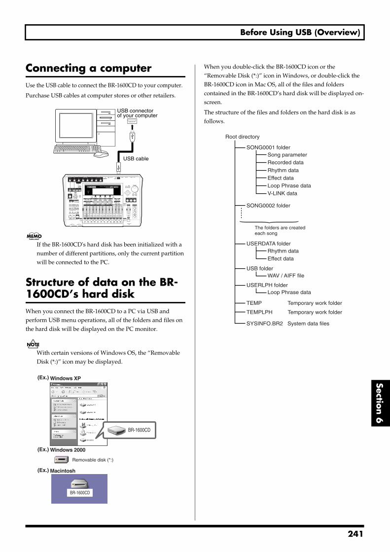
Before Using USB (Overview)
Section 6
Connecting a computerUse the USB cable to connect the BR-1600CD to your computer.
Purchase USB cables at computer stores or other retailers.fig.52-01
If the BR-1600CD's hard disk has been initialized with a number of different partitions, only the current partition will be connected to the PC.
Structure of data on the BR-1600CD’s hard diskWhen you connect the BR-1600CD to a PC via USB and perform USB menu operations, all of the folders and files on the hard disk will be displayed on the PC monitor.
With certain versions of Windows OS, the “Removable Disk (*:)” icon may be displayed.
fig.52-02
When you double-click the BR-1600CD icon or the “Removable Disk (*:)” icon in Windows, or double-click the BR-1600CD icon in Mac OS, all of the files and folders contained in the BR-1600CD’s hard disk will be displayed on-screen.
The structure of the files and folders on the hard disk is as follows.fig.52-03
USB cable
USB connectorof your computer
Windows XP
Windows 2000
Macintosh
BR-1600CD
BR-1600CD
Removable disk (*:)
(Ex.)
(Ex.)
(Ex.)
BR-1600CD
BR-1600CD
Root directory
SONG0001 folderSong parameterRecorded data
Rhythm data
Loop Phrase dataV-LINK data
Effect data
USERDATA folderRhythm dataEffect data
USB folderWAV / AIFF file
USERLPH folder
TEMP Temporary work folder
TEMPLPH Temporary work folder
SYSINFO.BR2 System data files
Loop Phrase data
SONG0002 folder
The folders are createdeach song
241
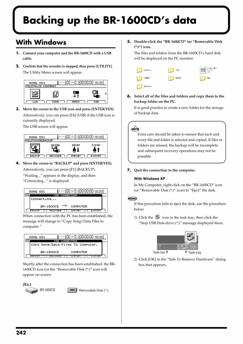
2
Backing up the BR-1600CD’s data
With Windows1. Connect your computer and the BR-1600CD with a USB
cable.
2. Confirm that the recorder is stopped, then press [UTILITY].
The Utility Menu screen will appear.fig.12-12d
3. Move the cursor to the USB icon and press [ENTER/YES].
Alternatively, you can press [F4] (USB) if the USB icon is currently displayed.
The USB screen will appear.fig.52-05d
4. Move the cursor to “BACKUP” and press [ENTER/YES].
Alternatively, you can press [F1] (BACKUP).
“Waiting...” appears in the display, and then “Connecting...” is displayed.
fig.52-06d
When connection with the PC has been established, the message will change to “Copy Song/Data Files to computer.”
fig.52-06ed
Shortly after the connection has been established, the BR-1600CD icon (or the “Removable Disk (*:)” icon will appear on-screen.
fig.52-07
5. Double-click the “BR-1600CD” (or “Removable Disk (*:)”) icon.
The files and folders from the BR-1600CD’s hard disk will be displayed on the PC monitor.
fig.52-08
6. Select all of the files and folders and copy them to the backup folder on the PC.
It is good practice to create a new folder for the storage of backup data.
7. Quit the connection to the computer.
With Windows XP
In My Computer, right-click on the “BR-1600CD” icon (or “Removable Disk (*:)” icon) to “Eject” the disk.
If this procedure fails to eject the disk, use the procedure below
1) Click the icon in the task tray, then click the “Stop USB Disk-drive (*:)” message displayed there.
fig.52-100
2) Click [OK] in the “Safe To Remove Hardware” dialog box that appears.
BR-1600CD Removable Disk (*:)
(Ex.)
Extra care should be taken to ensure that each and every file and folder is selected and copied. If files or folders are missed, the backup will be incomplete and subsequent recovery operations may not be possible.
Task trayTask bar
42
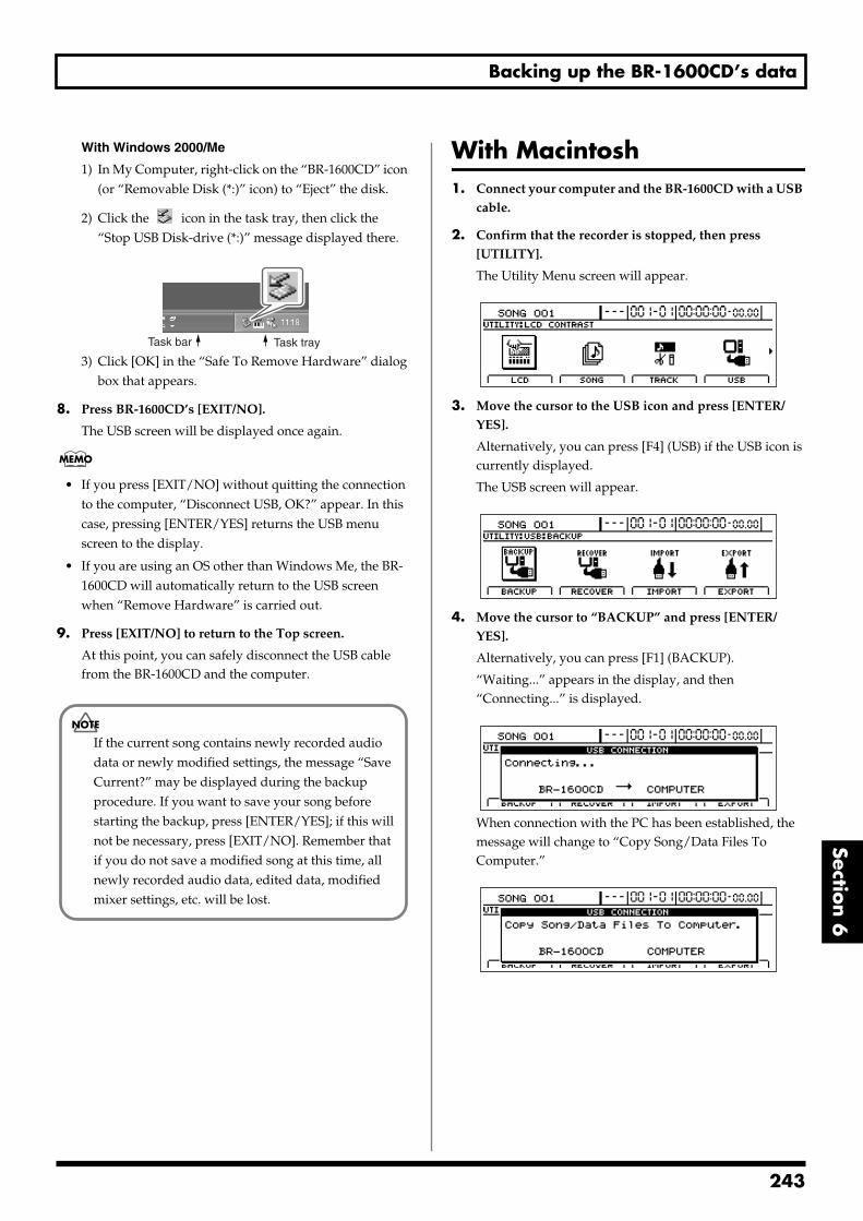
Backing up the BR-1600CD’s data
Section 6
With Windows 2000/Me
1) In My Computer, right-click on the “BR-1600CD” icon (or “Removable Disk (*:)” icon) to “Eject” the disk.
2) Click the icon in the task tray, then click the “Stop USB Disk-drive (*:)” message displayed there.
fig.52-100
3) Click [OK] in the “Safe To Remove Hardware” dialog box that appears.
8. Press BR-1600CD’s [EXIT/NO].
The USB screen will be displayed once again.
• If you press [EXIT/NO] without quitting the connection to the computer, “Disconnect USB, OK?” appear. In this case, pressing [ENTER/YES] returns the USB menu screen to the display.
• If you are using an OS other than Windows Me, the BR-1600CD will automatically return to the USB screen when “Remove Hardware” is carried out.
9. Press [EXIT/NO] to return to the Top screen.
At this point, you can safely disconnect the USB cable from the BR-1600CD and the computer.
With Macintosh1. Connect your computer and the BR-1600CD with a USB
cable.
2. Confirm that the recorder is stopped, then press [UTILITY].
The Utility Menu screen will appear.fig.12-12d
3. Move the cursor to the USB icon and press [ENTER/YES].
Alternatively, you can press [F4] (USB) if the USB icon is currently displayed.
The USB screen will appear.fig.52-05d
4. Move the cursor to “BACKUP” and press [ENTER/YES].
Alternatively, you can press [F1] (BACKUP).
“Waiting...” appears in the display, and then “Connecting...” is displayed.
fig.52-06d
When connection with the PC has been established, the message will change to “Copy Song/Data Files To Computer.”
fig.52-06ed
Task trayTask bar
If the current song contains newly recorded audio data or newly modified settings, the message “Save Current?” may be displayed during the backup procedure. If you want to save your song before starting the backup, press [ENTER/YES]; if this will not be necessary, press [EXIT/NO]. Remember that if you do not save a modified song at this time, all newly recorded audio data, edited data, modified mixer settings, etc. will be lost.
243
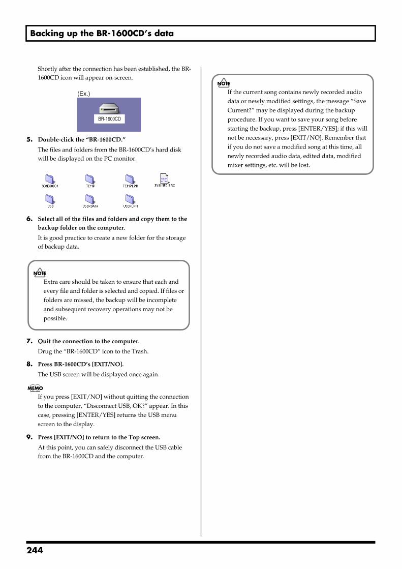
Backing up the BR-1600CD’s data
Shortly after the connection has been established, the BR-1600CD icon will appear on-screen.
fig.52-07a
5. Double-click the “BR-1600CD.”
The files and folders from the BR-1600CD’s hard disk will be displayed on the PC monitor.
fig.52-08
6. Select all of the files and folders and copy them to the backup folder on the computer.
It is good practice to create a new folder for the storage of backup data.
7. Quit the connection to the computer.
Drug the “BR-1600CD” icon to the Trash.
8. Press BR-1600CD’s [EXIT/NO].
The USB screen will be displayed once again.
If you press [EXIT/NO] without quitting the connection to the computer, “Disconnect USB, OK?” appear. In this case, pressing [ENTER/YES] returns the USB menu screen to the display.
9. Press [EXIT/NO] to return to the Top screen.
At this point, you can safely disconnect the USB cable from the BR-1600CD and the computer.
BR-1600CD
(Ex.)
Extra care should be taken to ensure that each and every file and folder is selected and copied. If files or folders are missed, the backup will be incomplete and subsequent recovery operations may not be possible.
If the current song contains newly recorded audio data or newly modified settings, the message “Save Current?” may be displayed during the backup procedure. If you want to save your song before starting the backup, press [ENTER/YES]; if this will not be necessary, press [EXIT/NO]. Remember that if you do not save a modified song at this time, all newly recorded audio data, edited data, modified mixer settings, etc. will be lost.
244
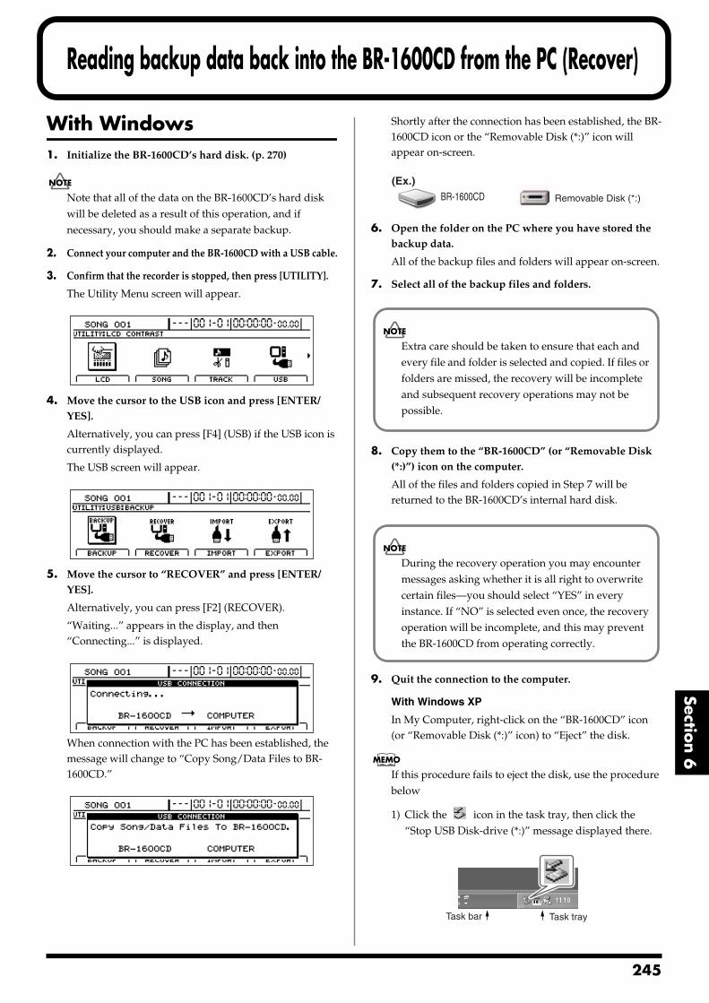
Reading backup data back into the BR-1600CD from the PC (Recover)
Section 6
With Windows1. Initialize the BR-1600CD’s hard disk. (p. 270)
Note that all of the data on the BR-1600CD’s hard disk will be deleted as a result of this operation, and if necessary, you should make a separate backup.
2. Connect your computer and the BR-1600CD with a USB cable.
3. Confirm that the recorder is stopped, then press [UTILITY].
The Utility Menu screen will appear.fig.12-12d
4. Move the cursor to the USB icon and press [ENTER/YES].
Alternatively, you can press [F4] (USB) if the USB icon is currently displayed.
The USB screen will appear.fig.52-05d
5. Move the cursor to “RECOVER” and press [ENTER/YES].
Alternatively, you can press [F2] (RECOVER).
“Waiting...” appears in the display, and then “Connecting...” is displayed.
fig.52-06d
When connection with the PC has been established, the message will change to “Copy Song/Data Files to BR-1600CD.”
fig.52-11ed
Shortly after the connection has been established, the BR-1600CD icon or the “Removable Disk (*:)” icon will appear on-screen.
fig.52-07
6. Open the folder on the PC where you have stored the backup data.
All of the backup files and folders will appear on-screen.
7. Select all of the backup files and folders.
8. Copy them to the “BR-1600CD” (or “Removable Disk (*:)”) icon on the computer.
All of the files and folders copied in Step 7 will be returned to the BR-1600CD’s internal hard disk.
9. Quit the connection to the computer.
With Windows XP
In My Computer, right-click on the “BR-1600CD” icon (or “Removable Disk (*:)” icon) to “Eject” the disk.
If this procedure fails to eject the disk, use the procedure below
1) Click the icon in the task tray, then click the “Stop USB Disk-drive (*:)” message displayed there.
fig.52-100
BR-1600CD Removable Disk (*:)
(Ex.)
Extra care should be taken to ensure that each and every file and folder is selected and copied. If files or folders are missed, the recovery will be incomplete and subsequent recovery operations may not be possible.
During the recovery operation you may encounter messages asking whether it is all right to overwrite certain files—you should select “YES” in every instance. If “NO” is selected even once, the recovery operation will be incomplete, and this may prevent the BR-1600CD from operating correctly.
Task trayTask bar
245
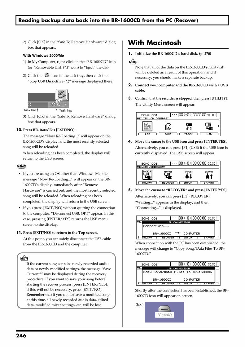
Reading backup data back into the BR-1600CD from the PC (Recover)
2) Click [OK] in the “Safe To Remove Hardware” dialog box that appears.
With Windows 2000/Me
1) In My Computer, right-click on the “BR-1600CD” icon (or “Removable Disk (*:)” icon) to “Eject” the disk.
2) Click the icon in the task tray, then click the “Stop USB Disk-drive (*:)” message displayed there.
fig.52-100
3) Click [OK] in the “Safe To Remove Hardware” dialog box that appears.
10. Press BR-1600CD’s [EXIT/NO].
The message “Now Re-Loading...” will appear on the BR-1600CD’s display, and the most recently selected song will be reloaded.
When reloading has been completed, the display will return to the USB screen.
• If you are using an OS other than Windows Me, the message “Now Re-Loading...” will appear on the BR-1600CD’s display immediately after “Remove Hardware” is carried out, and the most recently selected song will be reloaded. When reloading has been completed, the display will return to the USB screen.
• If you press [EXIT/NO] without quitting the connection to the computer, “Disconnect USB, OK?” appear. In this case, pressing [ENTER/YES] returns the USB menu screen to the display.
11. Press [EXIT/NO] to return to the Top screen.
At this point, you can safely disconnect the USB cable from the BR-1600CD and the computer.
With Macintosh1. Initialize the BR-1600CD’s hard disk. (p. 270)
Note that all of the data on the BR-1600CD’s hard disk will be deleted as a result of this operation, and if necessary, you should make a separate backup.
2. Connect your computer and the BR-1600CD with a USB cable.
3. Confirm that the recorder is stopped, then press [UTILITY].
The Utility Menu screen will appear.fig.12-12d
4. Move the cursor to the USB icon and press [ENTER/YES].
Alternatively, you can press [F4] (USB) if the USB icon is currently displayed. The USB screen will appear.
fig.52-05d
5. Move the cursor to “RECOVER” and press [ENTER/YES].
Alternatively, you can press [F2] (RECOVER).
“Waiting...” appears in the display, and then “Connecting...” is displayed.
fig.52-06d
When connection with the PC has been established, the message will change to “Copy Song/Data Files To BR-1600CD.”
fig.52-11ed
Shortly after the connection has been established, the BR-1600CD icon will appear on-screen.
fig.52-07b
Task trayTask bar
If the current song contains newly recorded audio data or newly modified settings, the message “Save Current?” may be displayed during the recovery procedure. If you want to save your song before starting the recover process, press [ENTER/YES]; if this will not be necessary, press [EXIT/NO]. Remember that if you do not save a modified song at this time, all newly recorded audio data, edited data, modified mixer settings, etc. will be lost.
BR-1600CD
(Ex.)
246
Reading backup data back into the BR-1600CD from the PC (Recover)
Section 6
With Mac OS 9.1.x / 9.2.x
6. Open the folder on the PC where you have stored the backup data.
All of the backup files and folders will appear on-screen.
7. Select all of the backup files and folders.
8. Copy them to the “BR-1600CD” icon on the computer.
All of the files and folders copied in Step 7 will be returned to the BR-1600CD’s internal hard disk.
9. Quit the connection to the computer.
Drug the BR-1600CD icon to the Trash.
10. Press BR-1600CD’s [EXIT/NO].
The message “Now Re-Loading...” will appear on the BR-1600CD’s display, and the most recently selected song will be reloaded.
When reloading has been completed, the display will return to the USB screen.
If you press [EXIT/NO] without quitting the connection to the computer, “Disconnect USB, OK?” appear. In this case, pressing [ENTER/YES] returns the USB menu screen to the display.
11. Press [EXIT/NO] to return to the Top screen.
At this point, you can safely disconnect the USB cable from the BR-1600CD and the computer.
With Mac OS X
6. Double-click the BR-1600CD icon.
The files and folders from the BR-1600CD’s hard disk will be displayed on the PC monitor.
fig.52-08ax
7. Open the folder on the PC where you have stored the backup data.
All of the backup files and folders will appear on-screen.
8. Select all of the backup files and folders.
9. Copy them to the USB folder on the computer.
All of the files and folders copied in Step 8 will be returned to the BR-1600CD’s internal hard disk.
10. Quit the connection to the computer.
Drug the BR-1600CD icon to the Trash.
11. Press BR-1600CD’s [EXIT/NO].
“Now Checking...” appears in the BR-1600CD’s display, then “Now Copying...” is displayed, and the recovery begins.
When the recovery is finished, the message “Now Re-Loading...” will appear in the display, and the most recently selected song will be reloaded.
When reloading has been completed, the display will return to the USB screen.
If you press [EXIT/NO] without quitting the connection to the computer, “Disconnect USB, OK?” appear. In this case, pressing [ENTER/YES] returns the USB menu screen to the display.
12. Press [EXIT/NO] to return to the Top screen.
At this point, you can safely disconnect the USB cable from the BR-1600CD and the computer.
Extra care should be taken to ensure that each and every file and folder is selected and copied. If files or folders are missed, the recovery will be incomplete and subsequent recovery operations may not be possible.
During the recovery operation you may encounter messages asking whether it is all right to overwrite certain files—you should select “YES” in every instance. If “NO” is selected even once, the recovery operation will be incomplete, and this may prevent the BR-1600CD from operating correctly.
If the current song contains newly recorded audio data or newly modified settings, the message “Save Current?” may be displayed during the recovery procedure. If you want to save your song before starting the recover process, press [ENTER/YES]; if this will not be necessary, press [EXIT/NO]. Remember that if you do not save a modified song at this time, all newly recorded audio data, edited data, modified mixer settings, etc. will be lost.
SYSINFO.BR2SONG0001 TEMP USERLPH
TEMPLPH USBUSB USBUSERDATA
Extra care should be taken to ensure that each and every file and folder is selected and copied. If files or folders are missed, the recovery will be incomplete and subsequent recovery operations may not be possible.
During the recovery operation you may encounter messages asking whether it is all right to overwrite certain files—you should select “YES” in every instance. If “NO” is selected even once, the recovery operation will be incomplete, and this may prevent the BR-1600CD from operating correctly.
247
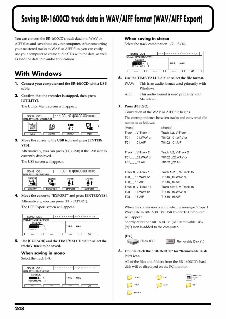
2
Saving BR-1600CD track data in WAV/AIFF format (WAV/AIFF Export)
You can convert the BR-1600CD’s track data into WAV or AIFF files and save these on your computer. After converting your mastered tracks to WAV or AIFF files, you can easily use your computer to create audio CDs with the data, as well as load the data into audio applications.
With Windows1. Connect your computer and the BR-1600CD with a USB
cable.
2. Confirm that the recorder is stopped, then press [UTILITY].
The Utility Menu screen will appear.fig.12-12d
3. Move the cursor to the USB icon and press [ENTER/YES].
Alternatively, you can press [F4] (USB) if the USB icon is currently displayed.
The USB screen will appear.fig.52-05d
4. Move the cursor to “EXPORT” and press [ENTER/YES].
Alternatively, you can press [F4] (EXPORT).
The USB Export screen will appear.fig.52-15ad
5. Use [CURSOR] and the TIME/VALUE dial to select the track/V-track to be saved.
When saving in monoSelect the track 1–8.
fig.52-15d
When saving in stereoSelect the track combination 1/2 –15/16.
fig.52-16d
6. Use the TIME/VALUE dial to select the file format.
WAV: This is an audio format used primarily with Windows.
AIFF: This audio format is used primarily with Macintosh.
7. Press [F4] (GO).
Conversion of the WAV or AIFF file begins.
The correspondence between tracks and converted file names is as follows.(Mono) (Stereo)
Track 1, V-Track 1 Track 1/2, V-Track 1
T01_ _ _01.WAV or T0102 _01.WAV or
T01_ _ _01.AIF T0102 _01.AIF
Track 1, V-Track 2 Track 1/2, V-Track 2
T01_ _ _02.WAV or T0102 _02.WAV or
T01_ _ _02.AIF T0102 _02.AIF
: :
Track 8, V-Track 15 Track 15/16, V-Track 15
T08_ _ 15.WAV or T1516_15.WAV or
T08_ _ 15.AIF T1516_15.AIF
Track 8, V-Track 16 Track 15/16, V-Track 16
T08_ _ 16.WAV or T1516_16.WAV or
T08_ _ 16.AIF T1516_16.AIF
When the conversion is complete, the message “Copy 1 Wave File In BR-1600CD’s USB Folder To Computer” will appear.Shortly after the “BR-1600CD” (or “Removable Disk (*:)”) icon is added to the computer.
fig.52-07
8. Double-click the “BR-1600CD” (or “Removable Disk (*:)”) icon.
All of the files and folders from the BR-1600CD’s hard disk will be displayed on the PC monitor.
fig.52-18
BR-1600CD Removable Disk (*:)
(Ex.)
48
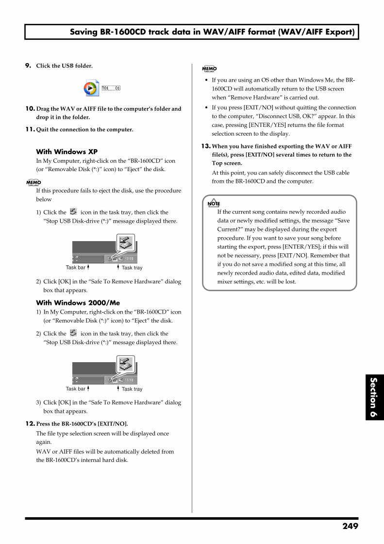
Saving BR-1600CD track data in WAV/AIFF format (WAV/AIFF Export)
Section 6
9. Click the USB folder.fig.52-19
10. Drag the WAV or AIFF file to the computer’s folder and drop it in the folder.
11. Quit the connection to the computer.
With Windows XPIn My Computer, right-click on the “BR-1600CD” icon (or “Removable Disk (*:)” icon) to “Eject” the disk.
If this procedure fails to eject the disk, use the procedure below
1) Click the icon in the task tray, then click the “Stop USB Disk-drive (*:)” message displayed there.
fig.52-100
2) Click [OK] in the “Safe To Remove Hardware” dialog box that appears.
With Windows 2000/Me1) In My Computer, right-click on the “BR-1600CD” icon
(or “Removable Disk (*:)” icon) to “Eject” the disk.
2) Click the icon in the task tray, then click the “Stop USB Disk-drive (*:)” message displayed there.
fig.52-100
3) Click [OK] in the “Safe To Remove Hardware” dialog box that appears.
12. Press the BR-1600CD’s [EXIT/NO].
The file type selection screen will be displayed once again.
WAV or AIFF files will be automatically deleted from the BR-1600CD’s internal hard disk.
• If you are using an OS other than Windows Me, the BR-1600CD will automatically return to the USB screen when “Remove Hardware” is carried out.
• If you press [EXIT/NO] without quitting the connection to the computer, “Disconnect USB, OK?” appear. In this case, pressing [ENTER/YES] returns the file format selection screen to the display.
13. When you have finished exporting the WAV or AIFF file(s), press [EXIT/NO] several times to return to the Top screen.
At this point, you can safely disconnect the USB cable from the BR-1600CD and the computer.
Task trayTask bar
Task trayTask bar
If the current song contains newly recorded audio data or newly modified settings, the message “Save Current?” may be displayed during the export procedure. If you want to save your song before starting the export, press [ENTER/YES]; if this will not be necessary, press [EXIT/NO]. Remember that if you do not save a modified song at this time, all newly recorded audio data, edited data, modified mixer settings, etc. will be lost.
249
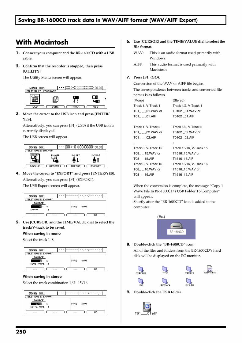
Saving BR-1600CD track data in WAV/AIFF format (WAV/AIFF Export)
With Macintosh1. Connect your computer and the BR-1600CD with a USB
cable.
2. Confirm that the recorder is stopped, then press [UTILITY].
The Utility Menu screen will appear.fig.12-12d
3. Move the cursor to the USB icon and press [ENTER/YES].
Alternatively, you can press [F4] (USB) if the USB icon is currently displayed.
The USB screen will appear.fig.52-05d
4. Move the cursor to “EXPORT” and press [ENTER/YES].
Alternatively, you can press [F4] (EXPORT).
The USB Export screen will appear.fig.52-15ad
5. Use [CURSOR] and the TIME/VALUE dial to select the track/V-track to be saved.
When saving in mono
Select the track 1–8.fig.52-15d
When saving in stereo
Select the track combination 1/2 –15/16.fig.52-16d
6. Use [CURSOR] and the TIME/VALUE dial to select the file format.
WAV: This is an audio format used primarily with Windows.
AIFF: This audio format is used primarily with Macintosh.
7. Press [F4] (GO).
Conversion of the WAV or AIFF file begins.
The correspondence between tracks and converted file names is as follows.(Mono) (Stereo)
Track 1, V-Track 1 Track 1/2, V-Track 1
T01_ _ _01.WAV or T0102 _01.WAV or
T01_ _ _01.AIF T0102 _01.AIF
Track 1, V-Track 2 Track 1/2, V-Track 2
T01_ _ _02.WAV or T0102 _02.WAV or
T01_ _ _02.AIF T0102 _02.AIF
: :
Track 8, V-Track 15 Track 15/16, V-Track 15
T08_ _ 15.WAV or T1516_15.WAV or
T08_ _ 15.AIF T1516_15.AIF
Track 8, V-Track 16 Track 15/16, V-Track 16
T08_ _ 16.WAV or T1516_16.WAV or
T08_ _ 16.AIF T1516_16.AIF
When the conversion is complete, the message “Copy 1 Wave File In BR-1600CD’s USB Folder To Computer” will appear.Shortly after the “BR-1600CD” icon is added to the computer.
fig.52-07a
8. Double-click the “BR-1600CD” icon.
All of the files and folders from the BR-1600CD’s hard disk will be displayed on the PC monitor.
fig.52-08a
9. Double-click the USB folder.fig.52-19a
BR-1600CD
(Ex.)
250
Saving BR-1600CD track data in WAV/AIFF format (WAV/AIFF Export)
Section 6
10. Drag the WAV or AIFF file to the computer’s folder and drop it in the folder.
11. Quit the connection to the computer.
Drug the “BR-1600CD” icon to the Trash.
12. Press the BR-1600CD’s [EXIT/NO].
The file type selection screen will be displayed once again.
WAV or AIFF files will be automatically deleted from the BR-1600CD’s internal hard disk.
If you press [EXIT/NO] without quitting the connection to the computer, “Disconnect USB, OK?” appear. In this case, pressing [ENTER/YES] returns the file format selection screen to the display.
13. When you have finished exporting the WAV or AIFF file(s), press [EXIT/NO] several times to return to the Top screen.
At this point, you can safely disconnect the USB cable from the BR-1600CD and the computer.
If the current song contains newly recorded audio data or newly modified settings, the message “Save Current?” may be displayed during the export procedure. If you want to save your song before starting the export, press [ENTER/YES]; if this will not be necessary, press [EXIT/NO]. Remember that if you do not save a modified song at this time, all newly recorded audio data, edited data, modified mixer settings, etc. will be lost.
251
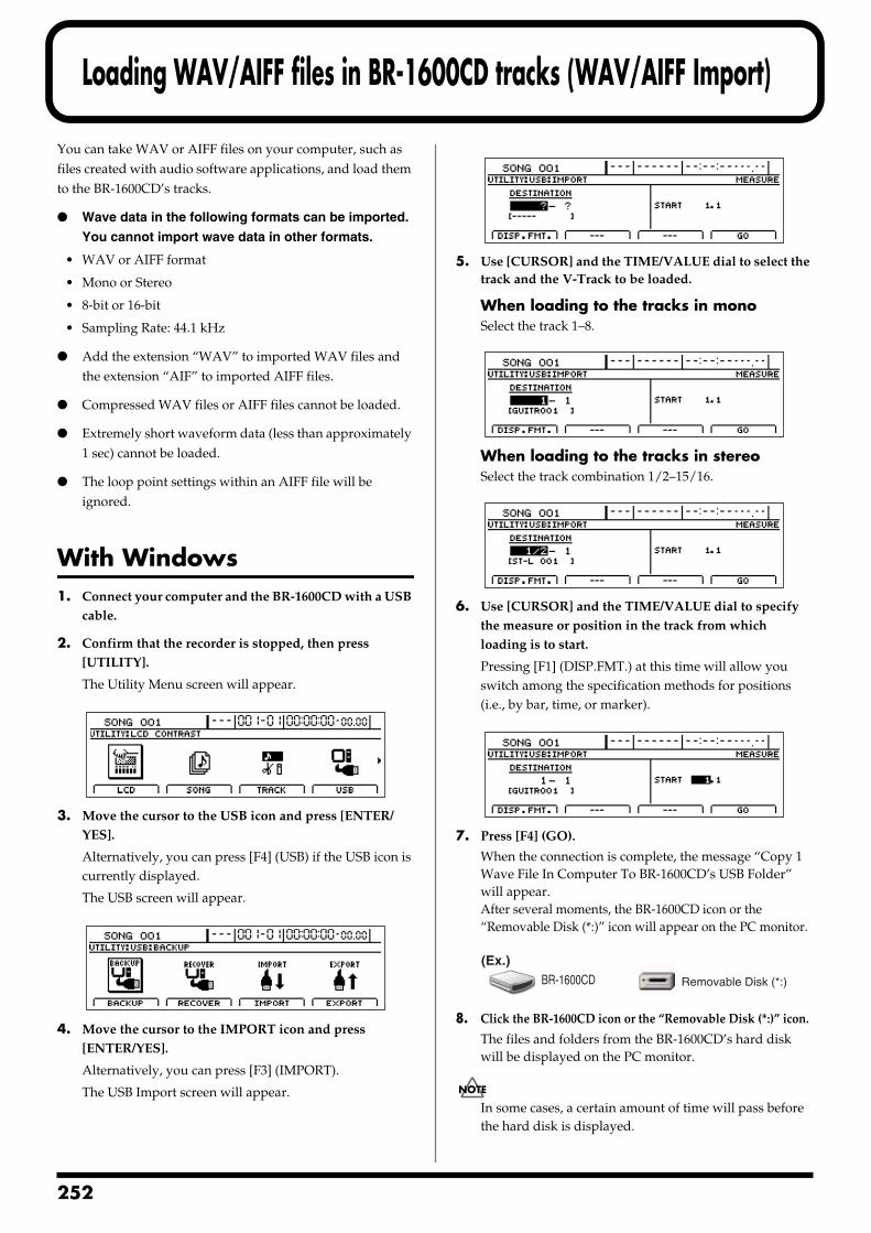
2
Loading WAV/AIFF files in BR-1600CD tracks (WAV/AIFF Import)
You can take WAV or AIFF files on your computer, such as files created with audio software applications, and load them to the BR-1600CD’s tracks.
Wave data in the following formats can be imported.
You cannot import wave data in other formats.
• WAV or AIFF format
• Mono or Stereo
• 8-bit or 16-bit
• Sampling Rate: 44.1 kHz
Add the extension “WAV” to imported WAV files and the extension “AIF” to imported AIFF files.
Compressed WAV files or AIFF files cannot be loaded.
Extremely short waveform data (less than approximately 1 sec) cannot be loaded.
The loop point settings within an AIFF file will be ignored.
With Windows1. Connect your computer and the BR-1600CD with a USB
cable.
2. Confirm that the recorder is stopped, then press [UTILITY].
The Utility Menu screen will appear.fig.12-12d
3. Move the cursor to the USB icon and press [ENTER/YES].
Alternatively, you can press [F4] (USB) if the USB icon is currently displayed.
The USB screen will appear.fig.52-05d
4. Move the cursor to the IMPORT icon and press [ENTER/YES].
Alternatively, you can press [F3] (IMPORT).
The USB Import screen will appear.
fig.52-22d
5. Use [CURSOR] and the TIME/VALUE dial to select the track and the V-Track to be loaded.
When loading to the tracks in monoSelect the track 1–8.
fig.52-23d
When loading to the tracks in stereoSelect the track combination 1/2–15/16.
fig.52-24d
6. Use [CURSOR] and the TIME/VALUE dial to specify the measure or position in the track from which loading is to start.
Pressing [F1] (DISP.FMT.) at this time will allow you switch among the specification methods for positions (i.e., by bar, time, or marker).
fig.52-25d
7. Press [F4] (GO).
When the connection is complete, the message “Copy 1 Wave File In Computer To BR-1600CD’s USB Folder” will appear.After several moments, the BR-1600CD icon or the “Removable Disk (*:)” icon will appear on the PC monitor.
fig.52-07
8. Click the BR-1600CD icon or the “Removable Disk (*:)” icon.
The files and folders from the BR-1600CD’s hard disk will be displayed on the PC monitor.
In some cases, a certain amount of time will pass before the hard disk is displayed.
BR-1600CD Removable Disk (*:)
(Ex.)
52
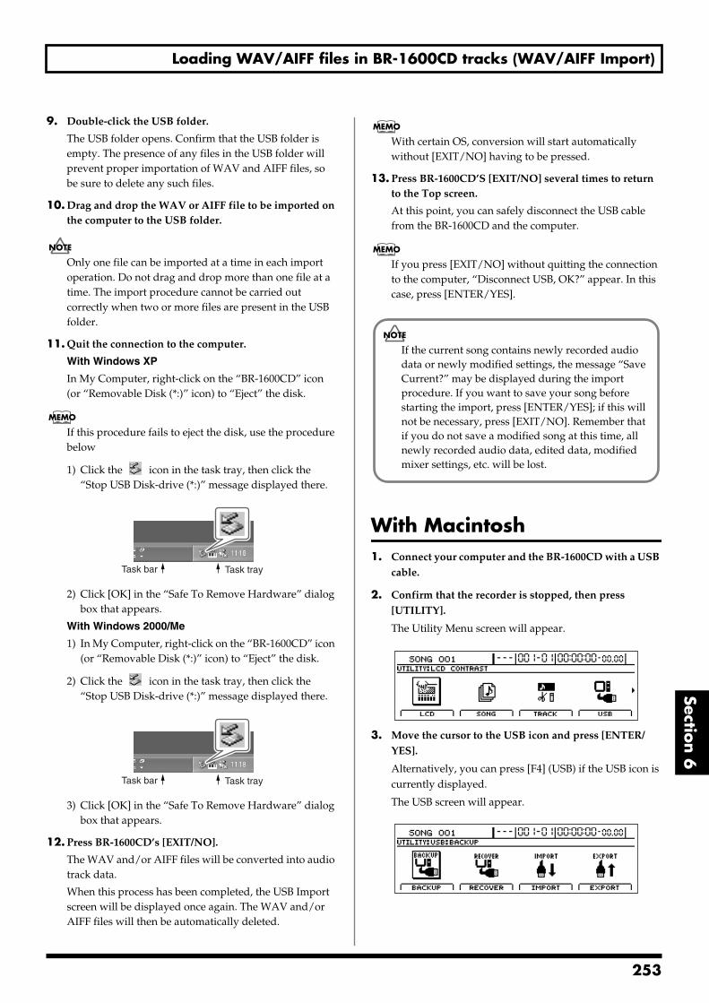
Loading WAV/AIFF files in BR-1600CD tracks (WAV/AIFF Import)
Section 6
9. Double-click the USB folder.
The USB folder opens. Confirm that the USB folder is empty. The presence of any files in the USB folder will prevent proper importation of WAV and AIFF files, so be sure to delete any such files.
10. Drag and drop the WAV or AIFF file to be imported on the computer to the USB folder.
Only one file can be imported at a time in each import operation. Do not drag and drop more than one file at a time. The import procedure cannot be carried out correctly when two or more files are present in the USB folder.
11. Quit the connection to the computer.
With Windows XP
In My Computer, right-click on the “BR-1600CD” icon (or “Removable Disk (*:)” icon) to “Eject” the disk.
If this procedure fails to eject the disk, use the procedure below
1) Click the icon in the task tray, then click the “Stop USB Disk-drive (*:)” message displayed there.
fig.52-100
2) Click [OK] in the “Safe To Remove Hardware” dialog box that appears.
With Windows 2000/Me
1) In My Computer, right-click on the “BR-1600CD” icon (or “Removable Disk (*:)” icon) to “Eject” the disk.
2) Click the icon in the task tray, then click the “Stop USB Disk-drive (*:)” message displayed there.
fig.52-100
3) Click [OK] in the “Safe To Remove Hardware” dialog box that appears.
12. Press BR-1600CD’s [EXIT/NO].
The WAV and/or AIFF files will be converted into audio track data.
When this process has been completed, the USB Import screen will be displayed once again. The WAV and/or AIFF files will then be automatically deleted.
With certain OS, conversion will start automatically without [EXIT/NO] having to be pressed.
13. Press BR-1600CD’S [EXIT/NO] several times to return to the Top screen.
At this point, you can safely disconnect the USB cable from the BR-1600CD and the computer.
If you press [EXIT/NO] without quitting the connection to the computer, “Disconnect USB, OK?” appear. In this case, press [ENTER/YES].
With Macintosh1. Connect your computer and the BR-1600CD with a USB
cable.
2. Confirm that the recorder is stopped, then press [UTILITY].
The Utility Menu screen will appear.fig.12-12d
3. Move the cursor to the USB icon and press [ENTER/YES].
Alternatively, you can press [F4] (USB) if the USB icon is currently displayed.
The USB screen will appear.fig.52-05d
Task trayTask bar
Task trayTask bar
If the current song contains newly recorded audio data or newly modified settings, the message “Save Current?” may be displayed during the import procedure. If you want to save your song before starting the import, press [ENTER/YES]; if this will not be necessary, press [EXIT/NO]. Remember that if you do not save a modified song at this time, all newly recorded audio data, edited data, modified mixer settings, etc. will be lost.
253
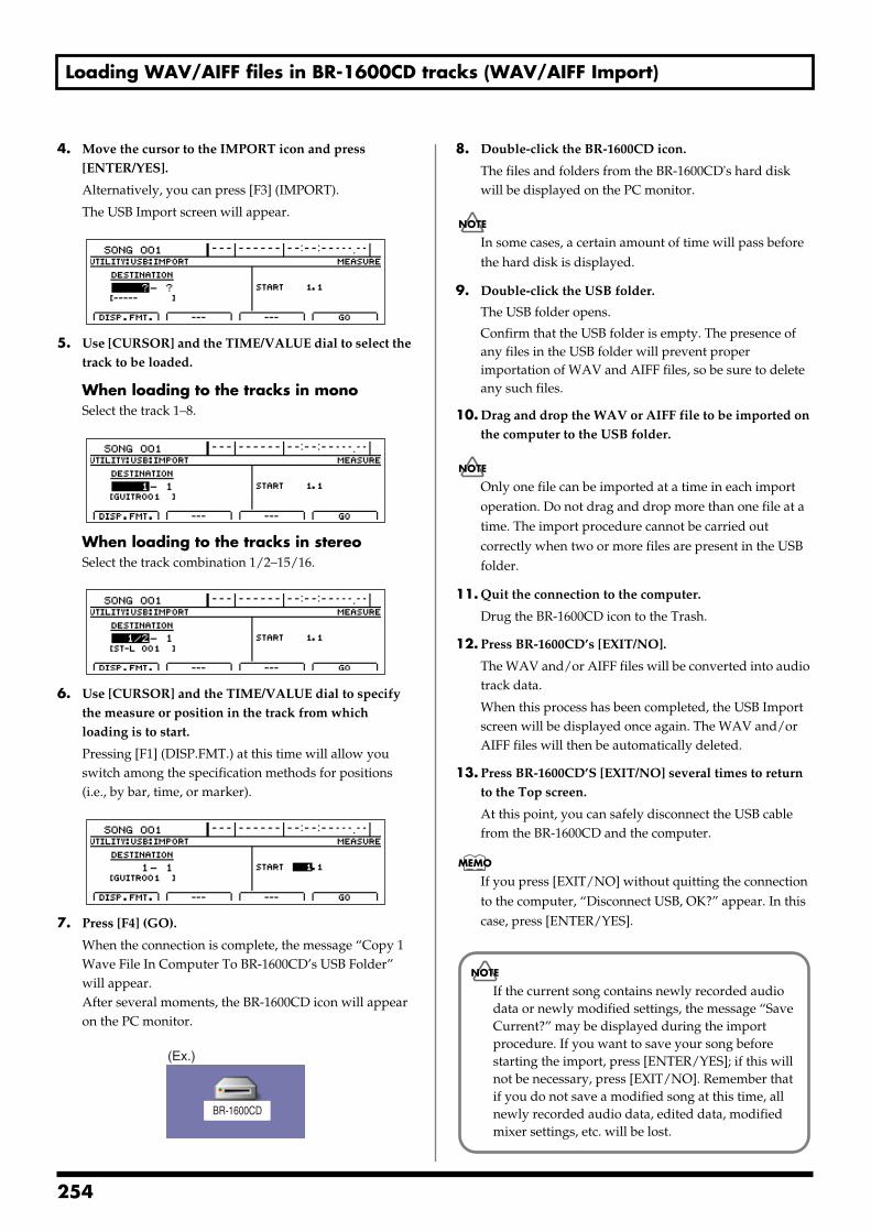
Loading WAV/AIFF files in BR-1600CD tracks (WAV/AIFF Import)
4. Move the cursor to the IMPORT icon and press [ENTER/YES].
Alternatively, you can press [F3] (IMPORT).
The USB Import screen will appear.fig.52-22d
5. Use [CURSOR] and the TIME/VALUE dial to select the track to be loaded.
When loading to the tracks in monoSelect the track 1–8.
fig.52-23d
When loading to the tracks in stereoSelect the track combination 1/2–15/16.
fig.52-24d
6. Use [CURSOR] and the TIME/VALUE dial to specify the measure or position in the track from which loading is to start.
Pressing [F1] (DISP.FMT.) at this time will allow you switch among the specification methods for positions (i.e., by bar, time, or marker).
fig.52-25d
7. Press [F4] (GO).
When the connection is complete, the message “Copy 1 Wave File In Computer To BR-1600CD’s USB Folder” will appear.After several moments, the BR-1600CD icon will appear on the PC monitor.
fig.52-07a
8. Double-click the BR-1600CD icon.
The files and folders from the BR-1600CD's hard disk will be displayed on the PC monitor.
In some cases, a certain amount of time will pass before the hard disk is displayed.
9. Double-click the USB folder.
The USB folder opens.
Confirm that the USB folder is empty. The presence of any files in the USB folder will prevent proper importation of WAV and AIFF files, so be sure to delete any such files.
10. Drag and drop the WAV or AIFF file to be imported on the computer to the USB folder.
Only one file can be imported at a time in each import operation. Do not drag and drop more than one file at a time. The import procedure cannot be carried out correctly when two or more files are present in the USB folder.
11. Quit the connection to the computer.
Drug the BR-1600CD icon to the Trash.
12. Press BR-1600CD’s [EXIT/NO].
The WAV and/or AIFF files will be converted into audio track data.
When this process has been completed, the USB Import screen will be displayed once again. The WAV and/or AIFF files will then be automatically deleted.
13. Press BR-1600CD’S [EXIT/NO] several times to return to the Top screen.
At this point, you can safely disconnect the USB cable from the BR-1600CD and the computer.
If you press [EXIT/NO] without quitting the connection to the computer, “Disconnect USB, OK?” appear. In this case, press [ENTER/YES].
BR-1600CD
(Ex.)
If the current song contains newly recorded audio data or newly modified settings, the message “Save Current?” may be displayed during the import procedure. If you want to save your song before starting the import, press [ENTER/YES]; if this will not be necessary, press [EXIT/NO]. Remember that if you do not save a modified song at this time, all newly recorded audio data, edited data, modified mixer settings, etc. will be lost.
254
Section 7 Other Convenient Functions
Section 7Other Convenient Functions
255
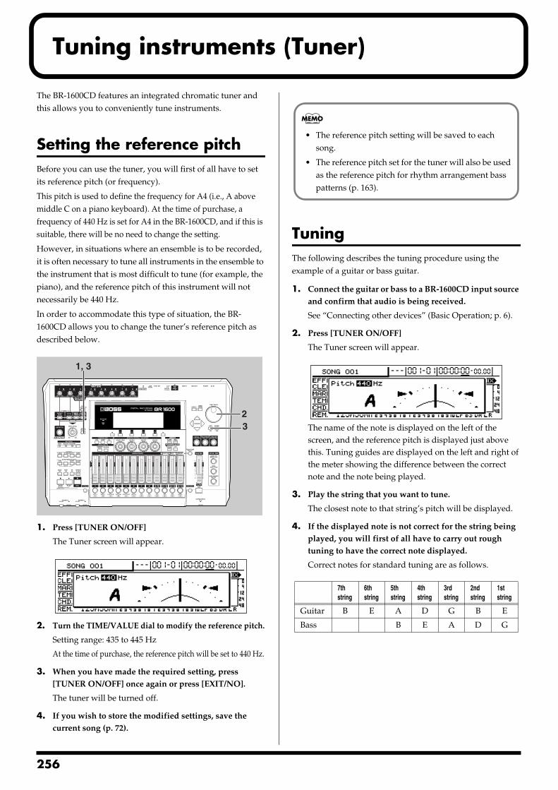
2
Tuning instruments (Tuner)
The BR-1600CD features an integrated chromatic tuner and this allows you to conveniently tune instruments.
Setting the reference pitchBefore you can use the tuner, you will first of all have to set its reference pitch (or frequency).
This pitch is used to define the frequency for A4 (i.e., A above middle C on a piano keyboard). At the time of purchase, a frequency of 440 Hz is set for A4 in the BR-1600CD, and if this is suitable, there will be no need to change the setting.
However, in situations where an ensemble is to be recorded, it is often necessary to tune all instruments in the ensemble to the instrument that is most difficult to tune (for example, the piano), and the reference pitch of this instrument will not necessarily be 440 Hz.
In order to accommodate this type of situation, the BR-1600CD allows you to change the tuner’s reference pitch as described below.fig.53-01
1. Press [TUNER ON/OFF]
The Tuner screen will appear. fig.53-02d
2. Turn the TIME/VALUE dial to modify the reference pitch.
Setting range: 435 to 445 Hz
At the time of purchase, the reference pitch will be set to 440 Hz.
3. When you have made the required setting, press [TUNER ON/OFF] once again or press [EXIT/NO].
The tuner will be turned off.
4. If you wish to store the modified settings, save the current song (p. 72).
TuningThe following describes the tuning procedure using the example of a guitar or bass guitar.
1. Connect the guitar or bass to a BR-1600CD input source and confirm that audio is being received.
See “Connecting other devices” (Basic Operation; p. 6).
2. Press [TUNER ON/OFF]
The Tuner screen will appear.fig.53-02d
The name of the note is displayed on the left of the screen, and the reference pitch is displayed just above this. Tuning guides are displayed on the left and right of the meter showing the difference between the correct note and the note being played.
3. Play the string that you want to tune.
The closest note to that string’s pitch will be displayed.
4. If the displayed note is not correct for the string being played, you will first of all have to carry out rough tuning to have the correct note displayed.
Correct notes for standard tuning are as follows.
1, 3
32
7th string
6th string
5th string
4th string
3rd string
2nd string
1st string
Guitar B E A D G B E
Bass B E A D G
• The reference pitch setting will be saved to each song.
• The reference pitch set for the tuner will also be used as the reference pitch for rhythm arrangement bass patterns (p. 163).
56
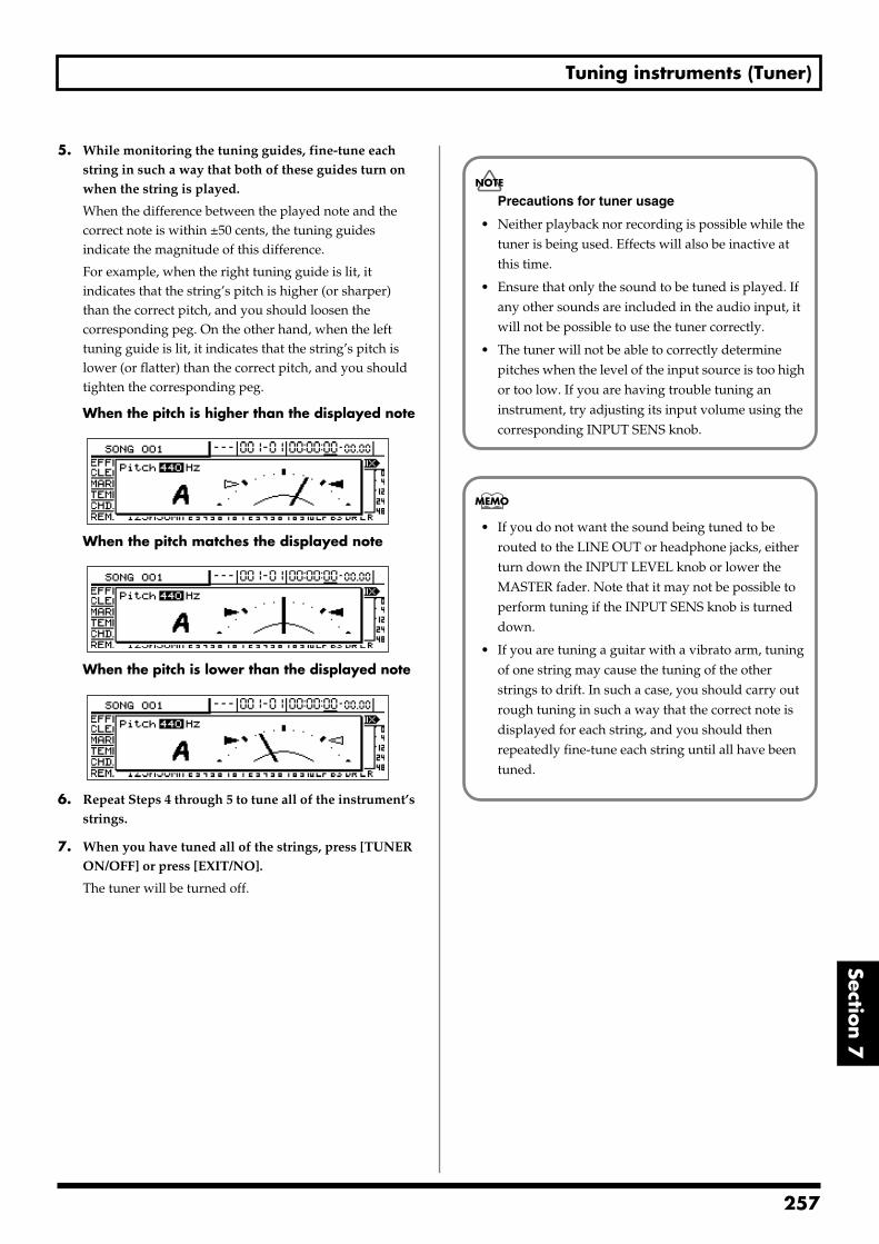
Tuning instruments (Tuner)
Section 7
5. While monitoring the tuning guides, fine-tune each string in such a way that both of these guides turn on when the string is played.
When the difference between the played note and the correct note is within ±50 cents, the tuning guides indicate the magnitude of this difference.
For example, when the right tuning guide is lit, it indicates that the string’s pitch is higher (or sharper) than the correct pitch, and you should loosen the corresponding peg. On the other hand, when the left tuning guide is lit, it indicates that the string’s pitch is lower (or flatter) than the correct pitch, and you should tighten the corresponding peg.
When the pitch is higher than the displayed notefig.53-04d
When the pitch matches the displayed notefig.53-02d
When the pitch is lower than the displayed notefig.53-04bd
6. Repeat Steps 4 through 5 to tune all of the instrument’s strings.
7. When you have tuned all of the strings, press [TUNER ON/OFF] or press [EXIT/NO].
The tuner will be turned off.
Precautions for tuner usage
• Neither playback nor recording is possible while the tuner is being used. Effects will also be inactive at this time.
• Ensure that only the sound to be tuned is played. If any other sounds are included in the audio input, it will not be possible to use the tuner correctly.
• The tuner will not be able to correctly determine pitches when the level of the input source is too high or too low. If you are having trouble tuning an instrument, try adjusting its input volume using the corresponding INPUT SENS knob.
• If you do not want the sound being tuned to be routed to the LINE OUT or headphone jacks, either turn down the INPUT LEVEL knob or lower the MASTER fader. Note that it may not be possible to perform tuning if the INPUT SENS knob is turned down.
• If you are tuning a guitar with a vibrato arm, tuning of one string may cause the tuning of the other strings to drift. In such a case, you should carry out rough tuning in such a way that the correct note is displayed for each string, and you should then repeatedly fine-tune each string until all have been tuned.
257
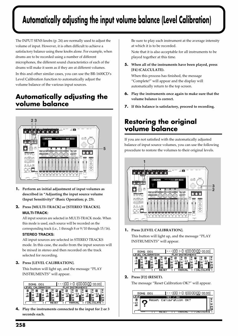
2
Automatically adjusting the input volume balance (Level Calibration)
The INPUT SENS knobs (p. 24) are normally used to adjust the volume of input. However, it is often difficult to achieve a satisfactory balance using these knobs alone. For example, when drums are to be recorded using a number of different microphones, the different sound characteristics of each of the drums will make it seem as if they are at different volumes.
In this and other similar cases, you can use the BR-1600CD’s Level Calibration function to automatically adjust the volume balance of the various input sources.
Automatically adjusting the volume balancefig.53-05
1. Perform an initial adjustment of input volumes as described in “Adjusting the input source volume (Input Sensitivity)” (Basic Operation; p. 25).
2. Press [MULTI-TRACK] or [STEREO TRACKS].
MULTI-TRACK:All input sources are selected in MULTI-TRACK mode. When this mode is used, each source will be recorded on the corresponding track (i.e., 1 through 8 or 9/10 through 15/16).
STEREO TRACKS:All input sources are selected in STEREO TRACKS mode. In this case, the audio from the input sources will be mixed in stereo and then recorded on the track selected for recording.
3. Press [LEVEL CALIBRATION].
This button will light up, and the message “PLAY INSTRUMENTS” will appear.
fig.53-06d
4. Play the instruments connected to the input for 2 or 3 seconds each.
Be sure to play each instrument at the average intensity at which it is to be recorded.
Note that it is also acceptable for all instruments to be played together at this time.
5. When all of the instruments have been played, press [F4] (CALCULATE).
When this process has finished, the message “Complete!” will appear and the display will automatically return to the top screen.
6. Play the instruments once again to make sure that the volume balance is correct.
7. If this balance is satisfactory, proceed to recording.
Restoring the original volume balanceIf you are not satisfied with the automatically adjusted balance of input source volumes, you can use the following procedure to restore the volumes to their original levels.fig.53-07
1. Press [LEVEL CALIBRATION].
This button will light up, and the message “PLAY INSTRUMENTS” will appear.
fig.53-06d
2. Press [F2] (RESET).
The message “Reset Calibration OK?” will appear.fig.53-09d
32
5
1
23
58
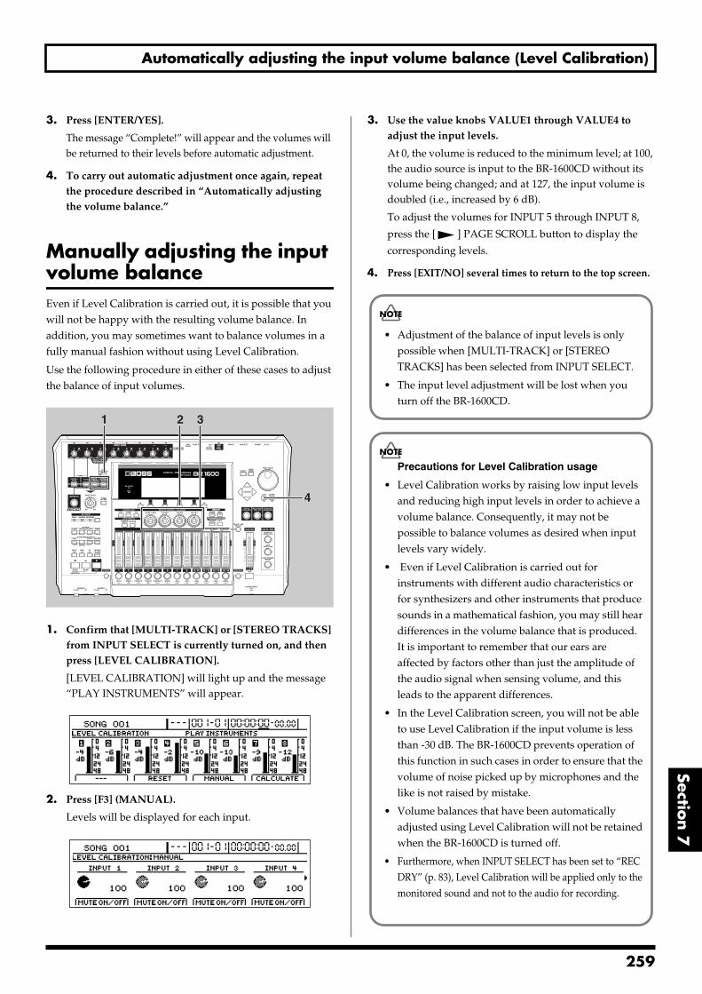
Automatically adjusting the input volume balance (Level Calibration)
Section 7
3. Press [ENTER/YES].
The message “Complete!” will appear and the volumes will be returned to their levels before automatic adjustment.
4. To carry out automatic adjustment once again, repeat the procedure described in “Automatically adjusting the volume balance.”
Manually adjusting the input volume balanceEven if Level Calibration is carried out, it is possible that you will not be happy with the resulting volume balance. In addition, you may sometimes want to balance volumes in a fully manual fashion without using Level Calibration.
Use the following procedure in either of these cases to adjust the balance of input volumes.fig.53-14
1. Confirm that [MULTI-TRACK] or [STEREO TRACKS] from INPUT SELECT is currently turned on, and then press [LEVEL CALIBRATION].
[LEVEL CALIBRATION] will light up and the message “PLAY INSTRUMENTS” will appear.
fig.53-06d
2. Press [F3] (MANUAL).
Levels will be displayed for each input.fig.53-100d
3. Use the value knobs VALUE1 through VALUE4 to adjust the input levels.
At 0, the volume is reduced to the minimum level; at 100, the audio source is input to the BR-1600CD without its volume being changed; and at 127, the input volume is doubled (i.e., increased by 6 dB).
To adjust the volumes for INPUT 5 through INPUT 8,
press the [ ] PAGE SCROLL button to display the
corresponding levels.
4. Press [EXIT/NO] several times to return to the top screen.
1 2 3
4
• Adjustment of the balance of input levels is only possible when [MULTI-TRACK] or [STEREO TRACKS] has been selected from INPUT SELECT.
• The input level adjustment will be lost when you turn off the BR-1600CD.
Precautions for Level Calibration usage
• Level Calibration works by raising low input levels and reducing high input levels in order to achieve a volume balance. Consequently, it may not be possible to balance volumes as desired when input levels vary widely.
• Even if Level Calibration is carried out for instruments with different audio characteristics or for synthesizers and other instruments that produce sounds in a mathematical fashion, you may still hear differences in the volume balance that is produced. It is important to remember that our ears are affected by factors other than just the amplitude of the audio signal when sensing volume, and this leads to the apparent differences.
• In the Level Calibration screen, you will not be able to use Level Calibration if the input volume is less than -30 dB. The BR-1600CD prevents operation of this function in such cases in order to ensure that the volume of noise picked up by microphones and the like is not raised by mistake.
• Volume balances that have been automatically adjusted using Level Calibration will not be retained when the BR-1600CD is turned off.
• Furthermore, when INPUT SELECT has been set to “REC DRY” (p. 83), Level Calibration will be applied only to the monitored sound and not to the audio for recording.
259
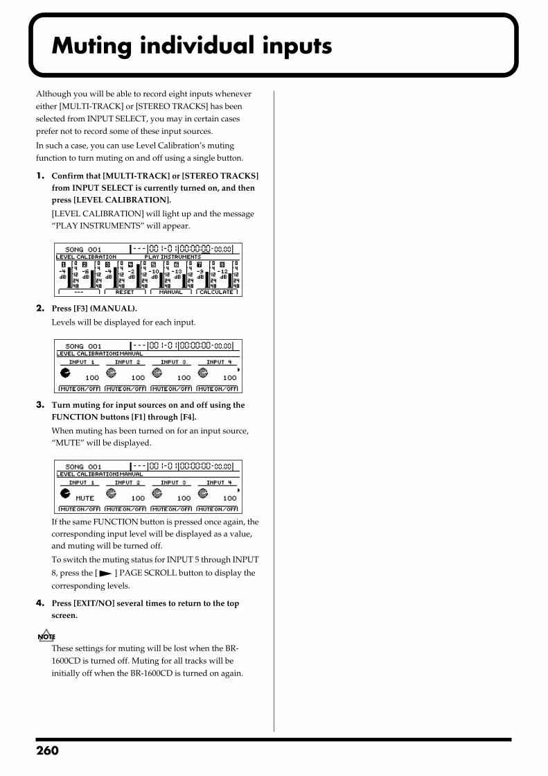
2
Muting individual inputs
Although you will be able to record eight inputs whenever either [MULTI-TRACK] or [STEREO TRACKS] has been selected from INPUT SELECT, you may in certain cases prefer not to record some of these input sources.
In such a case, you can use Level Calibration’s muting function to turn muting on and off using a single button.
1. Confirm that [MULTI-TRACK] or [STEREO TRACKS] from INPUT SELECT is currently turned on, and then press [LEVEL CALIBRATION].
[LEVEL CALIBRATION] will light up and the message “PLAY INSTRUMENTS” will appear.
fig.53-06d
2. Press [F3] (MANUAL).
Levels will be displayed for each input.fig.53-100d
3. Turn muting for input sources on and off using the FUNCTION buttons [F1] through [F4].
When muting has been turned on for an input source, “MUTE” will be displayed.
fig.53-200d
If the same FUNCTION button is pressed once again, the corresponding input level will be displayed as a value, and muting will be turned off.
To switch the muting status for INPUT 5 through INPUT
8, press the [ ] PAGE SCROLL button to display the
corresponding levels.
4. Press [EXIT/NO] several times to return to the top screen.
These settings for muting will be lost when the BR-1600CD is turned off. Muting for all tracks will be initially off when the BR-1600CD is turned on again.
60
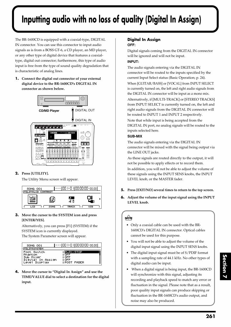
Inputting audio with no loss of quality (Digital In Assign)
Section 7
The BR-1600CD is equipped with a coaxial-type, DIGITAL IN connector. You can use this connector to input audio signals as is from a BOSS GT-6, a CD player, an MD player, or any other type of digital device that features a coaxial-type, digital out connector; furthermore, this type of audio input is free from the type of sound quality degradation that is characteristic of analog lines.
1. Connect the digital out connector of your external digital device to the BR-1600CD's DIGITAL IN connector as shown below.
fig.53-07a
2. Press [UTILITY].
The Utility Menu screen will appear.fig.12-12d
3. Move the cursor to the SYSTEM icon and press [ENTER/YES].
Alternatively, you can press [F1] (SYSTEM) if the SYSTEM icon is currently displayed.The System Parameter screen will appear.
fig.10-03d
4. Move the cursor to “Digital In Assign” and use the TIME/VALUE dial to select a destination for the digital input.
Digital In AssignOFF:
Digital signals coming from the DIGITAL IN connector will be ignored and will not be input.
INPUT:
The audio signals entering via the DIGITAL IN connector will be routed to the inputs specified by the current Input Select status (Basic Operation; p. 24).
When [GUITAR/BASS] or [VOCAL] from INPUT SELECT is currently turned on, the left and right audio signals from the DIGITAL IN connector will be input as a mono mix.
Alternatively, if [MULTI-TRACK] or [STEREO TRACKS] from INPUT SELECT is currently turned on, the left and right audio signals from the DIGITAL IN connector will be routed to INPUT 1 and INPUT 2 respectively.
Note that while input is being accepted from the DIGITAL IN port, no analog signals will be routed to the inputs selected here.
SUB-MIX
The audio signals entering via the DIGITAL IN connector will be mixed with the signal being output via the LINE OUT jacks.
As these signals are routed directly to the output, it will not be possible to apply effects or to record them.
In addition, you will not be able to adjust the volume of these signals using the INPUT SENS knobs, the INPUT LEVEL knob, or the MASTER fader.
5. Press [EXIT/NO] several times to return to the top screen.
6. Adjust the volume of the input signal using the INPUT LEVEL knob.
CD/MD Player
DIGITAL IN
DIGITAL OUT
• Only a coaxial cable can be used with the BR-1600CD's DIGITAL IN connector. Optical cables cannot be used for this purpose.
• You will not be able to adjust the volume of the digital input signal using the INPUT SENS knobs.
• The digital input signal must be of S/PDIF format with a sampling rate of 44.1 kHz. No other types of digital audio can be input.
• When a digital signal is being input, the BR-1600CD will synchronize with this signal, adjusting its recording and playback speed to match any error or fluctuation in the signal. Please note that as a result, poor quality input signals can produce skipping or fluctuation in the BR-1600CD's audio output, and noise may also be produced.
261
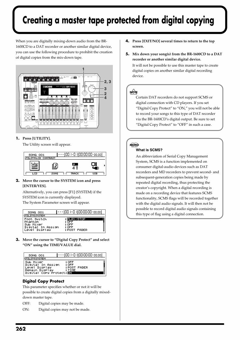
2
Creating a master tape protected from digital copying
When you are digitally mixing-down audio from the BR-1600CD to a DAT recorder or another similar digital device, you can use the following procedure to prohibit the creation of digital copies from the mix-down tape.fig.53-10
1. Press [UTILITY].
The Utility screen will appear.fig.12-12d
2. Move the cursor to the SYSTEM icon and press [ENTER/YES].
Alternatively, you can press [F1] (SYSTEM) if the SYSTEM icon is currently displayed.The System Parameter screen will appear.
fig.10-03d
3. Move the cursor to “Digital Copy Protect” and select “ON” using the TIME/VALUE dial.
fig.53-12d
Digital Copy ProtectThis parameter specifies whether or not it will be possible to create digital copies from a digitally mixed-down master tape.
OFF: Digital copies may be made.
ON: Digital copies may not be made.
4. Press [EXIT/NO] several times to return to the top screen.
5. Mix down your song(s) from the BR-1600CD to a DAT recorder or another similar digital device.
It will not be possible to use this master tape to create digital copies on another similar digital recording device.
1
24
2, 3
3
Certain DAT recorders do not support SCMS or digital connection with CD players. If you set “Digital Copy Protect” to “ON,” you will not be able to record your songs to this type of DAT recorder via the BR-1600CD’s digital output. Be sure to set “Digital Copy Protect” to “OFF” in such a case.
What is SCMS?
An abbreviation of Serial Copy Management System, SCMS is a function implemented on consumer digital-audio devices such as DAT recorders and MD recorders to prevent second- and subsequent-generation copies being made by repeated digital recording, thus protecting the creator’s copyright. When a digital recording is made on a recording device that features SCMS functionality, SCMS flags will be recorded together with the digital audio signals. It will then not be possible to record digital audio signals containing this type of flag using a digital connection.
62
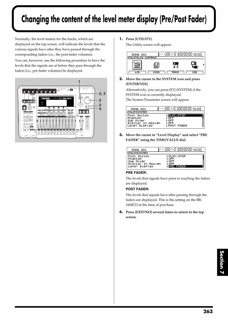
Changing the content of the level meter display (Pre/Post Fader)
Section 7
Normally, the level meters for the tracks, which are displayed on the top screen, will indicate the levels that the various signals have after they have passed through the corresponding faders (i.e., the post-fader volumes).
You can, however, use the following procedure to have the levels that the signals are at before they pass through the faders (i.e., pre-fader volumes) be displayed.fig.53-13
1. Press [UTILITY].
The Utility screen will appear.fig.12-12d
2. Move the cursor to the SYSTEM icon and press [ENTER/YES].
Alternatively, you can press [F1] (SYSTEM) if the SYSTEM icon is currently displayed.The System Parameter screen will appear.
fig.10-03d
3. Move the cursor to “Level Display” and select “PRE FADER” using the TIME/VALUE dial.
fig.53-16d
PRE FADER:
The levels that signals have prior to reaching the faders are displayed.
POST FADER:
The levels that signals have after passing through the faders are displayed. This is the setting on the BR-1600CD at the time of purchase.
4. Press [EXIT/NO] several times to return to the top screen.
1
24
2, 3
3
263
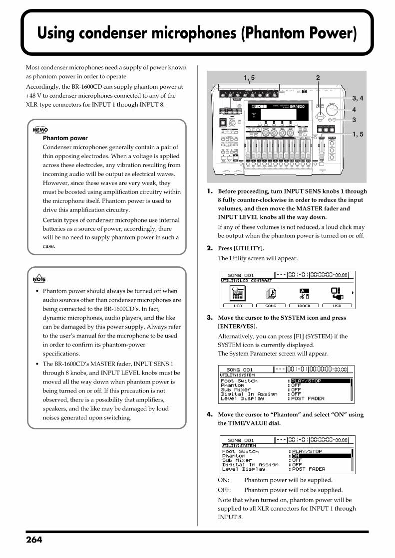
2
Using condenser microphones (Phantom Power)
Most condenser microphones need a supply of power known as phantom power in order to operate.
Accordingly, the BR-1600CD can supply phantom power at +48 V to condenser microphones connected to any of the XLR-type connectors for INPUT 1 through INPUT 8.
fig.53-17
1. Before proceeding, turn INPUT SENS knobs 1 through 8 fully counter-clockwise in order to reduce the input volumes, and then move the MASTER fader and INPUT LEVEL knobs all the way down.
If any of these volumes is not reduced, a loud click may be output when the phantom power is turned on or off.
2. Press [UTILITY].
The Utility screen will appear.fig.12-12d
3. Move the cursor to the SYSTEM icon and press [ENTER/YES].
Alternatively, you can press [F1] (SYSTEM) if the SYSTEM icon is currently displayed.The System Parameter screen will appear.
fig.10-03d
4. Move the cursor to “Phantom” and select “ON” using the TIME/VALUE dial.
fig.53-20d
ON: Phantom power will be supplied.
OFF: Phantom power will not be supplied.
Note that when turned on, phantom power will be supplied to all XLR connectors for INPUT 1 through INPUT 8.
Phantom power
Condenser microphones generally contain a pair of thin opposing electrodes. When a voltage is applied across these electrodes, any vibration resulting from incoming audio will be output as electrical waves. However, since these waves are very weak, they must be boosted using amplification circuitry within the microphone itself. Phantom power is used to drive this amplification circuitry.
Certain types of condenser microphone use internal batteries as a source of power; accordingly, there will be no need to supply phantom power in such a case.
• Phantom power should always be turned off when audio sources other than condenser microphones are being connected to the BR-1600CD’s. In fact, dynamic microphones, audio players, and the like can be damaged by this power supply. Always refer to the user’s manual for the microphone to be used in order to confirm its phantom-power specifications.
• The BR-1600CD’s MASTER fader, INPUT SENS 1 through 8 knobs, and INPUT LEVEL knobs must be moved all the way down when phantom power is being turned on or off. If this precaution is not observed, there is a possibility that amplifiers, speakers, and the like may be damaged by loud noises generated upon switching.
21, 5
3
3, 4
1, 5
4
64
Using condenser microphones (Phantom Power)
Section 7
5. Slowly raise the INPUT SENS knobs, the MASTER fader and INPUT LEVEL knobs, and confirm that an audio signal is being received from the condenser microphone(s).
6. To turn off the phantom power, repeat Steps 1 through 3, and then set “Phantom” to “OFF” in Step 4.
Precautions for phantom power usage
• Phantom power cannot be turned on or off individually for INPUT 1 through INPUT 8.
• Phantom power is not supplied to the 1/4” phone jacks for INPUT 1 through INPUT 8 or to the GUITAR/BASS jack.
• The phantom power setting reverts to “OFF” whenever the BR-1600CD is turned on. Remember, therefore, to turn on this power supply whenever it is needed.
• A supply of phantom power is not needed for certain types of condenser microphone (i.e., microphones featuring internal batteries, electric condenser microphones, etc.). Ensure that phantom power is set to “OFF” whenever one of these microphones is connected.
• No supply of phantom power will be needed from the BR-1600CD when using an external microphone pre-amp or a dedicated, external phantom power supply. Ensure that phantom power is set to “OFF” in all such cases.
265
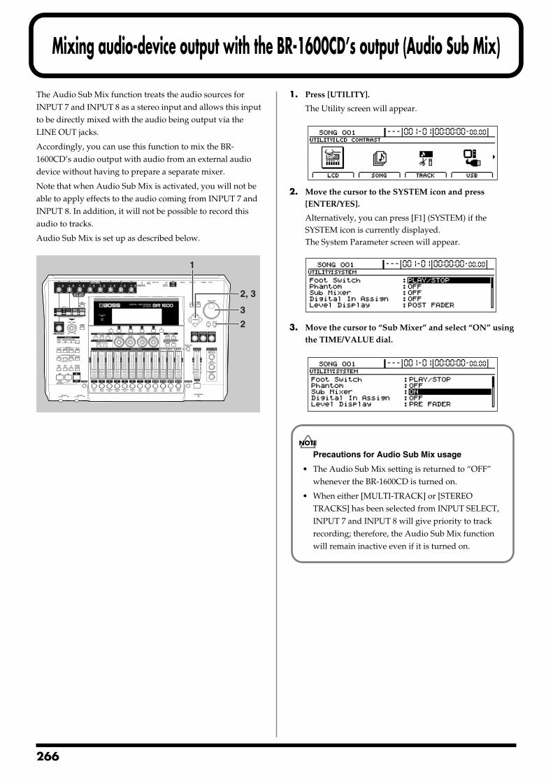
2
Mixing audio-device output with the BR-1600CD’s output (Audio Sub Mix)
The Audio Sub Mix function treats the audio sources for INPUT 7 and INPUT 8 as a stereo input and allows this input to be directly mixed with the audio being output via the LINE OUT jacks.
Accordingly, you can use this function to mix the BR-1600CD’s audio output with audio from an external audio device without having to prepare a separate mixer.
Note that when Audio Sub Mix is activated, you will not be able to apply effects to the audio coming from INPUT 7 and INPUT 8. In addition, it will not be possible to record this audio to tracks.
Audio Sub Mix is set up as described below.fig.53-21
1. Press [UTILITY].
The Utility screen will appear.fig.12-12d
2. Move the cursor to the SYSTEM icon and press [ENTER/YES].
Alternatively, you can press [F1] (SYSTEM) if the SYSTEM icon is currently displayed.The System Parameter screen will appear.
fig.10-03d
3. Move the cursor to “Sub Mixer” and select “ON” using the TIME/VALUE dial.
fig.53-24d
1
2
2, 3
3
Precautions for Audio Sub Mix usage
• The Audio Sub Mix setting is returned to “OFF” whenever the BR-1600CD is turned on.
• When either [MULTI-TRACK] or [STEREO TRACKS] has been selected from INPUT SELECT, INPUT 7 and INPUT 8 will give priority to track recording; therefore, the Audio Sub Mix function will remain inactive even if it is turned on.
66
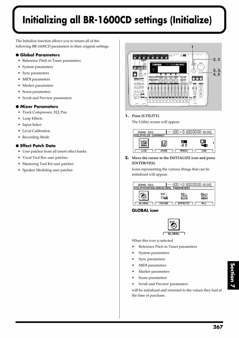
Initializing all BR-1600CD settings (Initialize)
Section 7
The Initialize function allows you to return all of the following BR-1600CD parameters to their original settings.
Global Parameters• Reference Pitch in Tuner parameters
• System parameters
• Sync parameters
• MIDI parameters
• Marker parameters
• Scene parameters
• Scrub and Preview parameters
Mixer Parameters• Track Compressor, EQ, Pan
• Loop Effects
• Input Select
• Level Calibration
• Recording Mode
Effect Patch Data• User patches from all insert effect banks
• Vocal Tool Box user patches
• Mastering Tool Kit user patches
• Speaker Modeling user patches
fig.53-28
1. Press [UTILITY].
The Utility screen will appear.fig.12-12d
2. Move the cursor to the INITIALIZE icon and press [ENTER/YES].
Icons representing the various things that can be initialized will appear.
fig.53-30d
GLOBAL iconfig.53-30d
When this icon is selected
• Reference Pitch in Tuner parameters
• System parameters
• Sync parameters
• MIDI parameters
• Marker parameters
• Scene parameters
• Scrub and Preview parameters
will be initialized and returned to the values they had at the time of purchase.
1
2, 3, 4, 5
2, 3
267
Initializing all BR-1600CD settings (Initialize)
MIXER iconfig.53-33d
When this icon is selected,
• Track Compressor, EQ, Pan
• Loop Effects
• Input Select
• Level Calibration
• Recording Mode
will be returned to the values they normally have immediately after Song New (Basic Operation; p. 22) is performed.
EFFECTS iconfig.53-32d
When this icon is selected,
• User patches from all insert effect banks
• Vocal Tool Box user patches
• Mastering Tool Kit user patches
• Speaker Modeling user patches
will be initialized and returned to their values at the time of purchase (i.e., the values for preset patches).
ALL iconfig.53-34d
When this icon is selected, all global parameters, effect patches, and mixer parameters will be initialized.
In addition, all data for song markers, Tempo Maps, Sync Tracks, scenes, and the like will be cleared. The display contrast will also be returned to the factory default contrast setting.
3. Move the cursor to the icon for the parameters to be initialized and press [ENTER/YES].
Alternatively, you can push the FUNCTION button below the relevant icon.
The message “Initialize *** OK?” will appear.
Example:) When GLOBAL icon is selectedfig.53-35d
4. Press [ENTER/YES].
The message “Sure?” will appear.fig.53-36d
5. Press [ENTER/YES] once again.
The BR-1600CD will start the initialization process. When this process has finished, the message “Complete!” will appear and you’ll automatically be returned to the top screen.
Precautions for initialization
• Press [EXIT/NO] if you want to cancel an initialization process.
• In certain cases, the message “Save Current?” will appear during the initialization procedure, and this indicates that the current song contains audio that has been newly recorded or edited, or modified parameters that have not yet been saved. If you want to save your song before starting the initialization process, press [ENTER/YES]; if this will not be necessary, press [EXIT/NO]. If you proceed without saving your song, all of the new recordings, audio edits, and new parameter settings will be permanently lost.
268
Performing hard disk operations
Section 7
Viewing information about the hard disk (Hard Disk Information)To display the hard disk data use the following procedure.fig.53-28
1. Press [UTILITY].
The Utility screen will appear.fig.12-12d
2. Move the cursor to the HDD icon and press [ENTER/YES].
The Hard Disk screen will appear.fig.54-02d
3. Move the cursor to the INFO icon and press [ENTER/YES].
The size of each partition appears.fig.54-03d
The capacity of the hard disk is displayed in units of 1 MB (i.e., 1,04,576 bytes).
The currently selected partition is indicated by an asterisk (“*”).
The BR-1600CD is set with one partition at the factory, so only one partition will appear in the display.
4. If you want to switch the partition being used, move the cursor to the partition you want to use, then press [ENTER/YES].The message “Now Loading...” appears.When “Complete!” appears, the switch is completed.
1
2,3,4
2,3,4
• In certain cases, the message “Save Current?” will appear during the initialization procedure, and this indicates that the current song contains audio that has been newly recorded or edited, or modified parameters that have not yet been saved. If you want to save your song before switching the partition, press [ENTER/YES]; if this will not be necessary, press [EXIT/NO]. If you proceed without saving your song, all of the new recordings, audio edits, and new parameter settings will be permanently lost.
• Drives can be switched only when multiple drives have been created.
269
Performing hard disk operations
Initializing the hard disk (Disk Initialize)The appropriate settings for the internal hard disk were made before the BR-1600CD left the factory, so it is ready for immediate use.
If for any reason the hard disk can no longer be written to or read from, or if you immediately want to delete all data from the disk, you can carry out Disk Initialize.
fig.53-28
1. Press [UTILITY].
The Utility screen will appear.fig.12-12d
2. Move the cursor to the HDD icon and press [ENTER/YES].
The Hard Disk screen will appear.fig.54-02d
3. Move the cursor to the INITIALIZE icon and press [ENTER/YES].
The message “FORMAT MODE: NORMAL” appears.fig.54-04d
4. Use the TIME/VALUE dial to select the initialization mode.
NORMALThis is the usual format. The hard disk is formatted as a single partition. The maximum partition size is 40 GB.
SURFACE SCANThe entire hard disk is formatted as “NORMAL” after all of the storage sectors of the hard disk are checked.
With a 40 GB hard disk, such checking takes roughly 2–3 hours to complete.
If you press [EXIT/NO] while the check is still in progress, the check is stopped at that point, and formatting continues in “NORMAL” mode.
DIV 2 through 8This separates the hard disk into drives (partitions) of equal size. You cannot set the drives so that they are of different sizes.
Example) When using “DIV 5” in formatting the partitions on a 40 GB hard disk.40GB / 5 = 8 GB
This creates five partitions, each containing 8 GB.The maximum size for a single partition is 40 GB.
Initialization is set to “NORMAL” at the factory.
5. Press [F4] (GO).
The message “Sure?” appears.fig.54-05d
• Take care to note that all data on the hard disk is lost when you execute Disk Initialize. The demo songs programmed at the factory are also deleted.
• We recommend creating a backup of your data on a CD-R/RW disc or other media as your situation requires.
15
2,3,6
4
6
2,3
270
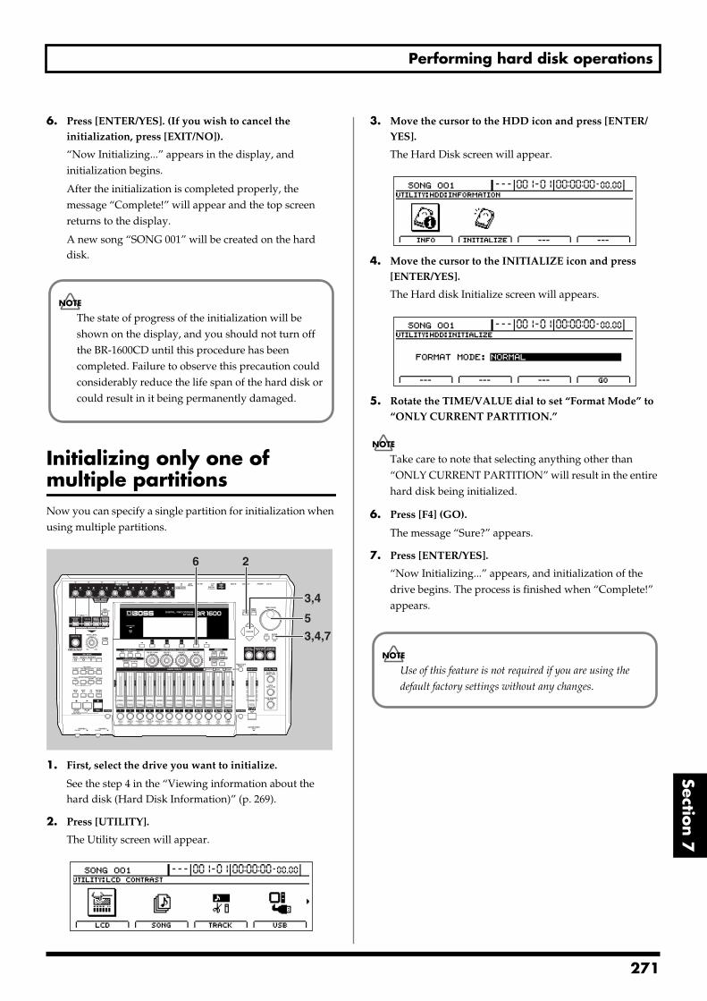
Performing hard disk operations
Section 7
6. Press [ENTER/YES]. (If you wish to cancel the initialization, press [EXIT/NO]).
“Now Initializing...” appears in the display, and initialization begins.
After the initialization is completed properly, the message “Complete!” will appear and the top screen returns to the display.
A new song “SONG 001” will be created on the hard disk.
Initializing only one of multiple partitionsNow you can specify a single partition for initialization when using multiple partitions.fig.53-28
1. First, select the drive you want to initialize.
See the step 4 in the “Viewing information about the hard disk (Hard Disk Information)” (p. 269).
2. Press [UTILITY].
The Utility screen will appear.fig.12-12d
3. Move the cursor to the HDD icon and press [ENTER/YES].
The Hard Disk screen will appear.fig.54-02d
4. Move the cursor to the INITIALIZE icon and press [ENTER/YES].
The Hard disk Initialize screen will appears.fig.54-04d
5. Rotate the TIME/VALUE dial to set “Format Mode” to “ONLY CURRENT PARTITION.”
Take care to note that selecting anything other than “ONLY CURRENT PARTITION” will result in the entire hard disk being initialized.
6. Press [F4] (GO).
The message “Sure?” appears.
7. Press [ENTER/YES].
“Now Initializing...” appears, and initialization of the drive begins. The process is finished when “Complete!” appears.
The state of progress of the initialization will be shown on the display, and you should not turn off the BR-1600CD until this procedure has been completed. Failure to observe this precaution could considerably reduce the life span of the hard disk or could result in it being permanently damaged.
26
3,4,7
5
3,4
Use of this feature is not required if you are using the
default factory settings without any changes.
271

MEMO
272

Appendices
Appendices273
2
Troubleshooting
If the BR-1600CD does not function as you expect, please check the following points before assuming that a malfunction has occurred. If this does not resolve the problem, contact a nearby Roland service center or your dealer.
Problems with the sound
No sound Is the power of the BR-1600CD and of the connected
equipment turned on?
Is the optical cable connected correctly?
Are any audio cables broken?
Has the volume of the connected amp or mixer been lowered?
Has the master fader or headphone volume of the BR-1600CD been lowered?
Was the heel end of the expression pedal all the way down?
Are you attempting to play back a short phrase of less than 0.5 seconds? (Phrases of 0.5 seconds or less cannot be played.)
Has the Mastering Tool Kit Auto Fade In/Out function been set to ON while the BR-1600CD is being used in Mastering mode?
When the Auto Fade In/Out function is set to ON, sounds may not be played, depending on the location of the playback.
Has the “Metronome” system parameter been set correctly?
If “METRONOME ONLY” has been set, no audio other than the metronome will be heard.
The volume level of the instrument connected to INPUT/MIC or GUITAR BASS jack is too low. Could you be using a connection cable that contains
a resistor?
Use a connection cable that does not contain a resistor.
A specific track cannot be heard Has the track volume been lowered?
In some cases the actual volume level may not match the position of the fader, for example when the scene has been switched. If so, move the fader up and down so that the volume level will match the fader position.
Has the track been muted? (The REC TRACK indicator will be blinking in green.)
Is the V-Track setting for a different V-Track?
Has the track type been set correctly?
Is the BR-1600CD in Mastering mode?
In Mastering mode, sounds are output only from Tracks 9/10.
The input cannot be heard Has the sound source been correctly connected to
either an input jack or connector?
If a connection is made to both the 1/4” phone mono jack and the XLR connector, priority will be given to the 1/4” phone mono jack.
The INPUT 1/MIC 1 jack (or XLR connector) and the GUITAR/BASS jack share the same internal circuitry, and when a connection has been made to both of these input jacks, the GUITAR/BASS jack will be selected automatically.
Did you adjust the SENS knob?
Has INPUT SELECT been muted? (The INPUT SELECT indicator will be dark.)
Has the INPUT LEVEL knob been set to “MIN”?
If [F3] (MANUAL) was selected on the Level Calibration screen (“Manually adjusting the input volume balance” (p. 259)), were the input levels set correctly?
Check whether the input level has been set to 0 or whether the corresponding track has been set to “MUTED.”
If you are using a condenser microphone, is phantom power turned on?
Is the BR-1600CD in Mastering mode?
Input-source sounds are not output in Mastering mode. Use with the BR-1600CD switched to Input mode.
Was the heel end of the expression pedal all the way down?
Can’t use the expression pedal to control an effect Is the minimum volume set to “0” or to an
appropriate value? (p. 84)
Is the effect (Foot Volume, Pitch Shifter, Wah, Vibtaro) that you wish to control from the expression pedal turned on?
The expression pedal can control all of the above effects simultaneously.
Is the type (P.Shift Type, Wah Type) of the effect you wish to control set to “PEDAL” ?
74
Troubleshooting
Appendices
Cannot record Does the hard disk have insufficient remaining
capacity?
Has the recording mode (INPUT, BOUNCE, MASTERING) been selected correctly?
Has the Scrub Playback function been turned on?
Digital input cannot be received from an external device, or digital recording on an external device is not possible Does the sampling rate of the BR-1600CD match that
of the digital audio device?
Set the digital audio device to a sampling rate of 44.1 kHz.
Does the digital signal format match?
Your digital audio device may use a non-standard digital signal format. Connect the BR-1600CD to a digital audio device that supports CP-1201 or S/P DIF.
In cases where digital input cannot be received:Is Digital In Assign (p. 261) set to "OFF"?
The recorded sound contains noise or distortion Is the input sensitivity set appropriately?
If the input sensitivity is too high, the recorded sound will be distorted. If it is too low, the input sound will be buried in noise. Adjust the SENS knob so that the level meter moves as much as possible without causing the PEAK indicator to light.
Are the effect settings appropriate?
Using overdrive, distortion, or compression with the insert effects may increase noise and distortion.
Are the equalizer settings appropriate?
Some equalizer settings can cause the sound to distort even though the PEAK indicator does not light. Readjust the equalizer.
Are the track output levels appropriate?
If you hear noise or distortion after bouncing tracks, the output level of the tracks was too high.
Is a mic with high output impedance connected directly to the BR-1600CD?
The BR-1600CD is designed with a wide margin of headroom. Also, since the MIC 1 and MIC 2 jacks are low impedance inputs, the recording level may be too low, depending on the response of some mics. In such cases, connect the mic via a mic preamp to the BR-1600CD, so that they can be boosted to line level before recording.
Problems with the hard disk
Hard disk data was damagedIf hard disk data has been damaged, the following causes are possible. Please initialize the hard disk (using physical formatting) once again. (p. 270)
Was the power turned off while the disk drive was operating?
Was a strong physical shock applied to the disk drive?
Little available space remaining on the hard disk Do you have numerous recorded songs and/or loop
phrases stored on the hard disk?
Is [SIMUL], [STEREO TRACKS] or [MULTI-TRACK] selected for the INPUT SELECT, or are stereo tracks selected for the recording tracks?
Recording with stereo tracks halves the remaining recording time, and this is indicated in the display.
If [MULTI-TRACK] is selected and recording is carried out on all 8 tracks, only 1/8th of the original recording time will be available.
Was the drive partitioned into multiple drives (partitions) when it was initialized?
Problems with the CD-R/RW drive
Cannot remove the CD-R/RW disc Is the power turned on?
The CD-R/RW disc cannot be removed unless the power is turned on.
CIs a screen for reading from, or writing to CD-R/RW discs showing in the display?
It is not possible to eject the disc when you’re in a screen for reading/writing CD-R/RW discs. Press [EXIT] a number of times to return to the top screen, then press the EJECT button again.
Cannot read from/write to CD-R/RW discs Is the BR-1600CD in a level position?
Was a strong physical shock applied to the CD-R/RW drive?
Is the disc correctly placed in the CD-R/RW drive?
Are you using the right type of CD-R/RW disc?
275
Troubleshooting
Are you using a CD-R disc that has already been written to, or a CD-RW disc that may be too old?
Is the CD-R/RW drive being “force ejected?”
Pressing a straightened paper clip or similar object into the “emergency eject hole” in the CD-R/RW drive’s front side forces ejection of the CD-R/RW disc. However, the CD-R/RW drive may not operate correctly after this is done. Should this be the case, turn off the power, then turn it back on again.
Synchronization problems
Cannot synchronizeWhen using MTC to synchronize the BR-1600CD with a MIDI sequencer, the BR-1600CD must be the master device.
Is the MIDI cable connected correctly?
Is the MIDI cable broken?
Has the sync generator been set to the desired synchronization method (MTC or MIDI Clock)? (p. 226)
If you are synchronizing with MTC, has the other device been set to the same MTC type? (p. 227)
Has the MIDI sequencer been set correctly?
Is the MIDI sequencer ready to play back?
Does the other device support the MMC commands of the BR-1600CD?
Cannot record MIDI Clock (cannot use the sync track) Is the external MIDI sequencer set to transmit MIDI
Clock/Start/Stop?
Cannot control faders using MIDI Is the MIDI cable connecting the external MIDI
sequencer connected correctly?
Have you made the settings that enable the external MIDI sequencer to record and play back the fader information transmitted from the BR-1600CD?
Fader messages are transmitted and received using Control Change #7 (Volume). The external MIDI sequencer must be set so it is able to transmit and receive such MIDI messages.
Problems with USB
The message “Waiting...” does not turn off Is the USB cable properly connected?
Is your computer's operating system compatible with the BR-1600CD?Windows: Windows Me/2000 /XPMacintosh: Mac OS 9.1.x, 9.2.x, Mac OS X
Other problems
When the power is turned on, the previous data has not been saved correctlyIt is possible that the power of the BR-1600CD was turned off without using the POWER switch. The lost data cannot be recovered.
276
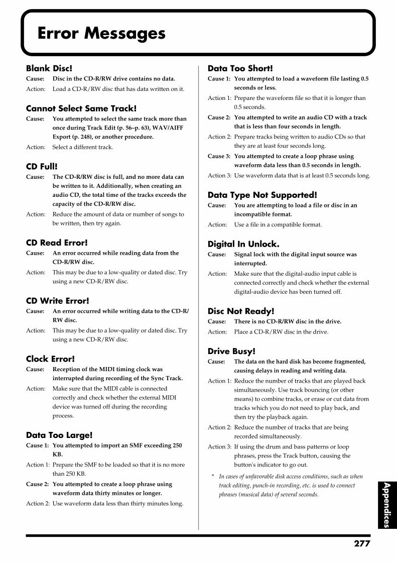
Error Messages
Appendices
Blank Disc!Cause: Disc in the CD-R/RW drive contains no data.
Action: Load a CD-R/RW disc that has data written on it.
Cannot Select Same Track!Cause: You attempted to select the same track more than
once during Track Edit (p. 56–p. 63), WAV/AIFF
Export (p. 248), or another procedure.
Action: Select a different track.
CD Full!Cause: The CD-R/RW disc is full, and no more data can
be written to it. Additionally, when creating an
audio CD, the total time of the tracks exceeds the
capacity of the CD-R/RW disc.
Action: Reduce the amount of data or number of songs to be written, then try again.
CD Read Error!Cause: An error occurred while reading data from the
CD-R/RW disc.
Action: This may be due to a low-quality or dated disc. Try using a new CD-R/RW disc.
CD Write Error!Cause: An error occurred while writing data to the CD-R/
RW disc.
Action: This may be due to a low-quality or dated disc. Try using a new CD-R/RW disc.
Clock Error!Cause: Reception of the MIDI timing clock was
interrupted during recording of the Sync Track.
Action: Make sure that the MIDI cable is connected correctly and check whether the external MIDI device was turned off during the recording process.
Data Too Large!Cause 1: You attempted to import an SMF exceeding 250
KB.
Action 1: Prepare the SMF to be loaded so that it is no more than 250 KB.
Cause 2: You attempted to create a loop phrase using
waveform data thirty minutes or longer.
Action 2: Use waveform data less than thirty minutes long.
Data Too Short!Cause 1: You attempted to load a waveform file lasting 0.5
seconds or less.
Action 1: Prepare the waveform file so that it is longer than 0.5 seconds.
Cause 2: You attempted to write an audio CD with a track
that is less than four seconds in length.
Action 2: Prepare tracks being written to audio CDs so that they are at least four seconds long.
Cause 3: You attempted to create a loop phrase using
waveform data less than 0.5 seconds in length.
Action 3: Use waveform data that is at least 0.5 seconds long.
Data Type Not Supported!Cause: You are attempting to load a file or disc in an
incompatible format.
Action: Use a file in a compatible format.
Digital In Unlock.Cause: Signal lock with the digital input source was
interrupted.
Action: Make sure that the digital-audio input cable is connected correctly and check whether the external digital-audio device has been turned off.
Disc Not Ready!Cause: There is no CD-R/RW disc in the drive.
Action: Place a CD-R/RW disc in the drive.
Drive Busy!Cause: The data on the hard disk has become fragmented,
causing delays in reading and writing data.
Action 1: Reduce the number of tracks that are played back simultaneously. Use track bouncing (or other means) to combine tracks, or erase or cut data from tracks which you do not need to play back, and then try the playback again.
Action 2: Reduce the number of tracks that are being recorded simultaneously.
Action 3: If using the drum and bass patterns or loop phrases, press the Track button, causing the button's indicator to go out.
* In cases of unfavorable disk access conditions, such as when
track editing, punch-in recording, etc. is used to connect
phrases (musical data) of several seconds.
277
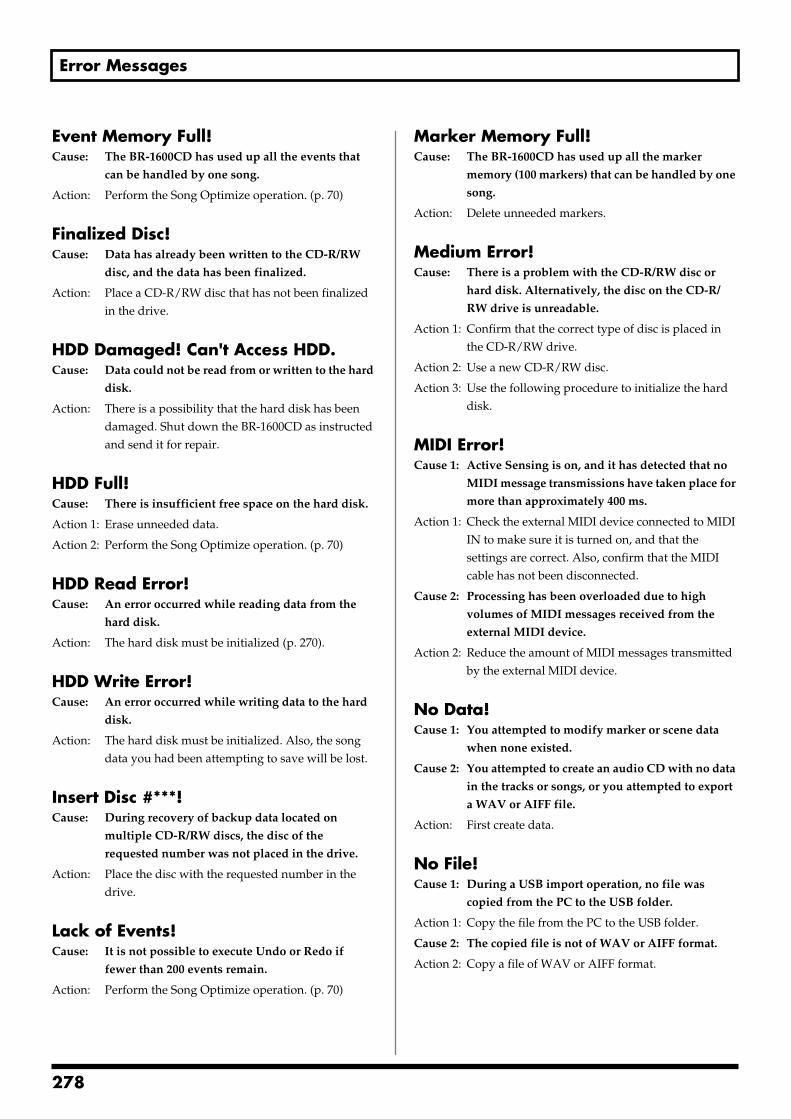
Error Messages
Event Memory Full!Cause: The BR-1600CD has used up all the events that
can be handled by one song.
Action: Perform the Song Optimize operation. (p. 70)
Finalized Disc!Cause: Data has already been written to the CD-R/RW
disc, and the data has been finalized.
Action: Place a CD-R/RW disc that has not been finalized in the drive.
HDD Damaged! Can't Access HDD.Cause: Data could not be read from or written to the hard
disk.
Action: There is a possibility that the hard disk has been damaged. Shut down the BR-1600CD as instructed and send it for repair.
HDD Full!Cause: There is insufficient free space on the hard disk.
Action 1: Erase unneeded data.
Action 2: Perform the Song Optimize operation. (p. 70)
HDD Read Error!Cause: An error occurred while reading data from the
hard disk.
Action: The hard disk must be initialized (p. 270).
HDD Write Error!Cause: An error occurred while writing data to the hard
disk.
Action: The hard disk must be initialized. Also, the song data you had been attempting to save will be lost.
Insert Disc #***!Cause: During recovery of backup data located on
multiple CD-R/RW discs, the disc of the
requested number was not placed in the drive.
Action: Place the disc with the requested number in the drive.
Lack of Events!Cause: It is not possible to execute Undo or Redo if
fewer than 200 events remain.
Action: Perform the Song Optimize operation. (p. 70)
Marker Memory Full!Cause: The BR-1600CD has used up all the marker
memory (100 markers) that can be handled by one
song.
Action: Delete unneeded markers.
Medium Error!Cause: There is a problem with the CD-R/RW disc or
hard disk. Alternatively, the disc on the CD-R/
RW drive is unreadable.
Action 1: Confirm that the correct type of disc is placed in the CD-R/RW drive.
Action 2: Use a new CD-R/RW disc.
Action 3: Use the following procedure to initialize the hard disk.
MIDI Error!Cause 1: Active Sensing is on, and it has detected that no
MIDI message transmissions have taken place for
more than approximately 400 ms.
Action 1: Check the external MIDI device connected to MIDI IN to make sure it is turned on, and that the settings are correct. Also, confirm that the MIDI cable has not been disconnected.
Cause 2: Processing has been overloaded due to high
volumes of MIDI messages received from the
external MIDI device.
Action 2: Reduce the amount of MIDI messages transmitted by the external MIDI device.
No Data!Cause 1: You attempted to modify marker or scene data
when none existed.
Cause 2: You attempted to create an audio CD with no data
in the tracks or songs, or you attempted to export
a WAV or AIFF file.
Action: First create data.
No File!Cause 1: During a USB import operation, no file was
copied from the PC to the USB folder.
Action 1: Copy the file from the PC to the USB folder.
Cause 2: The copied file is not of WAV or AIFF format.
Action 2: Copy a file of WAV or AIFF format.
278
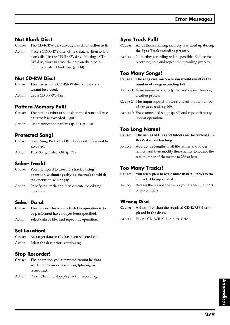
Error Messages
Appendices
Not Blank Disc!Cause: The CD-R/RW disc already has data written to it.
Action: Place a CD-R/RW disc with no data written to it (a blank disc) in the CD-R/RW drive.If using a CD-RW disc, you can erase the data on the disc in order to create a blank disc (p. 214).
Not CD-RW Disc!Cause: The disc is not a CD-R/RW disc, so the data
cannot be erased.
Action: Use a CD-R/RW disc.
Pattern Memory Full!Cause: The total number of sounds in the drum and bass
patterns has exceeded 10,000.
Action: Delete unneeded patterns (p. 161, p. 174).
Protected Song!Cause: Since Song Protect is ON, the operation cannot be
executed.
Action: Turn Song Protect Off. (p. 71)
Select Track!Cause: You attempted to execute a track editing
operation without specifying the track to which
the operation will apply.
Action: Specify the track, and then execute the editing operation.
Select Data!Cause: The data or files upon which the operation is to
be performed have not yet been specified.
Action: Select data or files and repeat the operation.
Set Location!Cause: No target data or file has been selected yet.
Action: Select the data before continuing.
Stop Recorder!Cause: The operation you attempted cannot be done
while the recorder is running (playing or
recording).
Action: Press [STOP] to stop playback or recording.
Sync Track Full!Cause: All of the remaining memory was used up during
the Sync Track recording process.
Action: No further recording will be possible. Reduce the recording time and repeat the recording process.
Too Many Songs!Cause 1: The song creation operation would result in the
number of songs exceeding 999.
Action 1: Erase unneeded songs (p. 69) and repeat the song creation process.
Cause 2: The import operation would result in the number
of songs exceeding 999.
Action 2: Erase unneeded songs (p. 69) and repeat the song import operation.
Too Long Name!Cause: The names of files and folders on the current CD-
R/RW disc are too long.
Action: Add up the lengths of all file names and folder names, and then modify these names to reduce the total number of characters to 236 or less.
Too Many Tracks!Cause: You attempted to write more than 99 tracks to the
audio CD being created.
Action: Reduce the number of tracks you are writing to 99 or fewer tracks.
Wrong Disc!Cause: A disc other than the required CD-R/RW disc is
placed in the drive.
Action: Place a CD-R/RW disc in the drive.
279
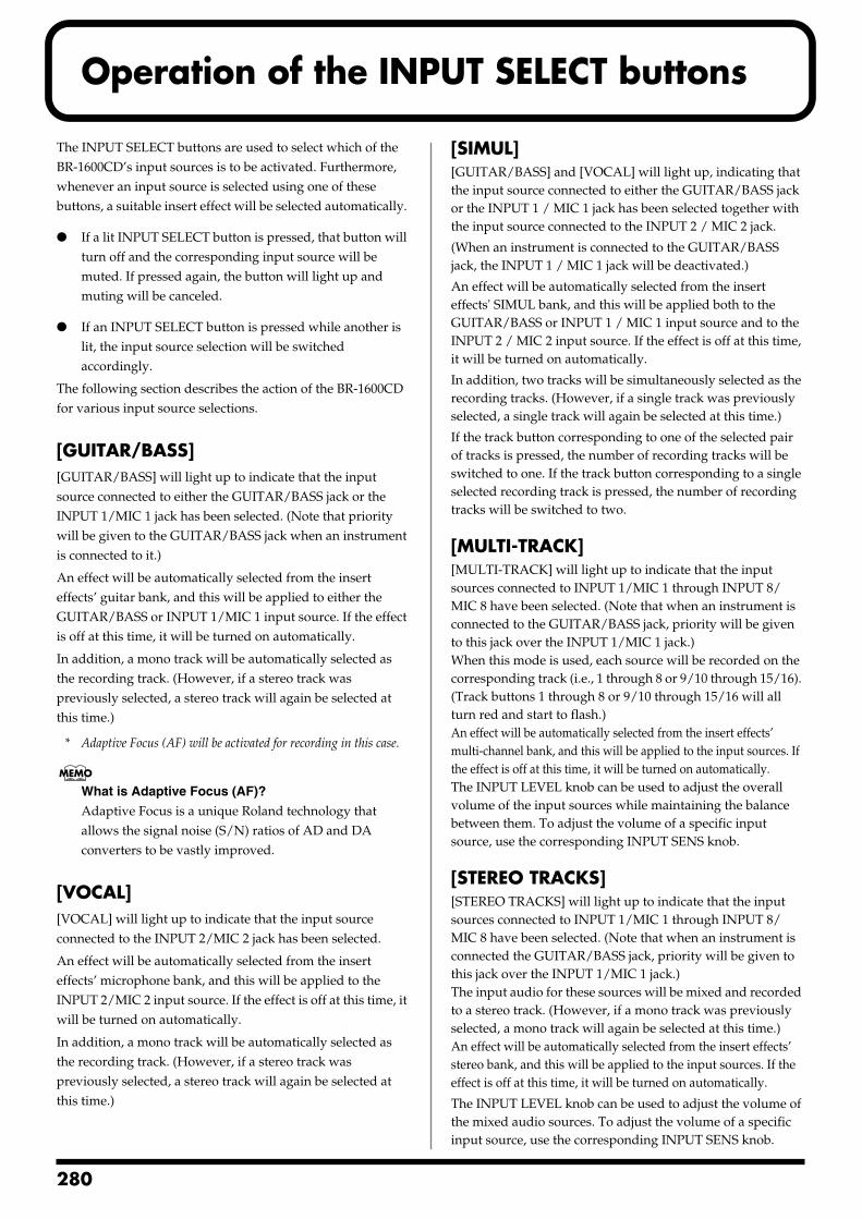
2
Operation of the INPUT SELECT buttons
The INPUT SELECT buttons are used to select which of the BR-1600CD’s input sources is to be activated. Furthermore, whenever an input source is selected using one of these buttons, a suitable insert effect will be selected automatically.
If a lit INPUT SELECT button is pressed, that button will turn off and the corresponding input source will be muted. If pressed again, the button will light up and muting will be canceled.
If an INPUT SELECT button is pressed while another is lit, the input source selection will be switched accordingly.
The following section describes the action of the BR-1600CD for various input source selections.
[GUITAR/BASS][GUITAR/BASS] will light up to indicate that the input source connected to either the GUITAR/BASS jack or the INPUT 1/MIC 1 jack has been selected. (Note that priority will be given to the GUITAR/BASS jack when an instrument is connected to it.)
An effect will be automatically selected from the insert effects’ guitar bank, and this will be applied to either the GUITAR/BASS or INPUT 1/MIC 1 input source. If the effect is off at this time, it will be turned on automatically.
In addition, a mono track will be automatically selected as the recording track. (However, if a stereo track was previously selected, a stereo track will again be selected at this time.)
* Adaptive Focus (AF) will be activated for recording in this case.
What is Adaptive Focus (AF)?
Adaptive Focus is a unique Roland technology that allows the signal noise (S/N) ratios of AD and DA converters to be vastly improved.
[VOCAL][VOCAL] will light up to indicate that the input source connected to the INPUT 2/MIC 2 jack has been selected.
An effect will be automatically selected from the insert effects’ microphone bank, and this will be applied to the INPUT 2/MIC 2 input source. If the effect is off at this time, it will be turned on automatically.
In addition, a mono track will be automatically selected as the recording track. (However, if a stereo track was previously selected, a stereo track will again be selected at this time.)
[SIMUL][GUITAR/BASS] and [VOCAL] will light up, indicating that the input source connected to either the GUITAR/BASS jack or the INPUT 1 / MIC 1 jack has been selected together with the input source connected to the INPUT 2 / MIC 2 jack.
(When an instrument is connected to the GUITAR/BASS jack, the INPUT 1 / MIC 1 jack will be deactivated.)
An effect will be automatically selected from the insert effects' SIMUL bank, and this will be applied both to the GUITAR/BASS or INPUT 1 / MIC 1 input source and to the INPUT 2 / MIC 2 input source. If the effect is off at this time, it will be turned on automatically.
In addition, two tracks will be simultaneously selected as the recording tracks. (However, if a single track was previously selected, a single track will again be selected at this time.)
If the track button corresponding to one of the selected pair of tracks is pressed, the number of recording tracks will be switched to one. If the track button corresponding to a single selected recording track is pressed, the number of recording tracks will be switched to two.
[MULTI-TRACK][MULTI-TRACK] will light up to indicate that the input sources connected to INPUT 1/MIC 1 through INPUT 8/MIC 8 have been selected. (Note that when an instrument is connected to the GUITAR/BASS jack, priority will be given to this jack over the INPUT 1/MIC 1 jack.) When this mode is used, each source will be recorded on the corresponding track (i.e., 1 through 8 or 9/10 through 15/16). (Track buttons 1 through 8 or 9/10 through 15/16 will all turn red and start to flash.)An effect will be automatically selected from the insert effects’ multi-channel bank, and this will be applied to the input sources. If the effect is off at this time, it will be turned on automatically.The INPUT LEVEL knob can be used to adjust the overall volume of the input sources while maintaining the balance between them. To adjust the volume of a specific input source, use the corresponding INPUT SENS knob.
[STEREO TRACKS][STEREO TRACKS] will light up to indicate that the input sources connected to INPUT 1/MIC 1 through INPUT 8/MIC 8 have been selected. (Note that when an instrument is connected the GUITAR/BASS jack, priority will be given to this jack over the INPUT 1/MIC 1 jack.) The input audio for these sources will be mixed and recorded to a stereo track. (However, if a mono track was previously selected, a mono track will again be selected at this time.)An effect will be automatically selected from the insert effects’ stereo bank, and this will be applied to the input sources. If the effect is off at this time, it will be turned on automatically.
The INPUT LEVEL knob can be used to adjust the volume of the mixed audio sources. To adjust the volume of a specific input source, use the corresponding INPUT SENS knob.
80
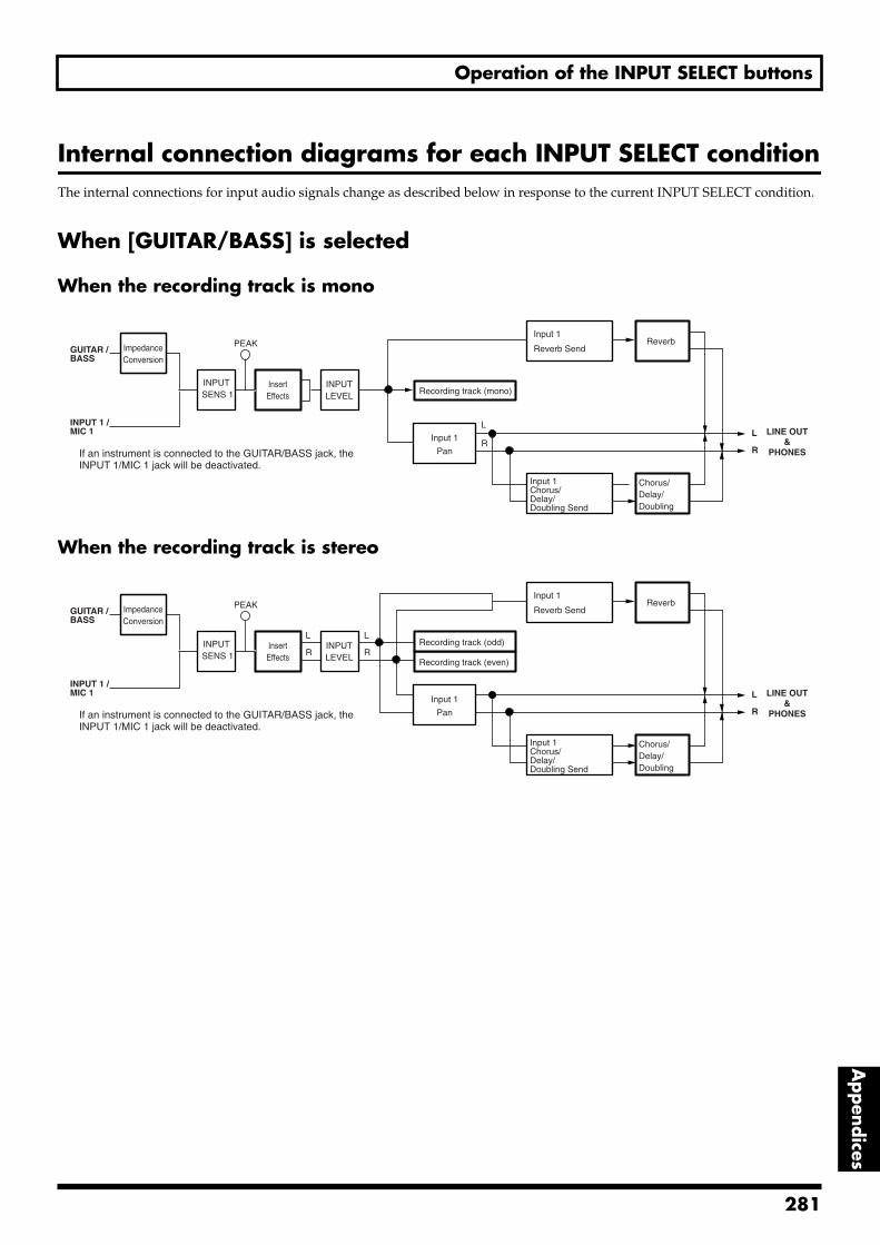
Operation of the INPUT SELECT buttons
Appendices
Internal connection diagrams for each INPUT SELECT conditionThe internal connections for input audio signals change as described below in response to the current INPUT SELECT condition.
When [GUITAR/BASS] is selected
When the recording track is monofig.92-01
When the recording track is stereofig.92-02
Chorus/Delay/Doubling
LINE OUT&
PHONES
L
RInput 1
Pan
Reverb
INPUTLEVEL
InsertEffects Recording track (mono)
GUITAR / BASS
INPUT 1 /MIC 1
INPUT SENS 1
ImpedanceConversion
Input 1
Reverb SendPEAK
Input 1Chorus/Delay/Doubling Send
L
RIf an instrument is connected to the GUITAR/BASS jack, the INPUT 1/MIC 1 jack will be deactivated.
Chorus/Delay/Doubling
LINE OUT&
PHONES
L
RInput 1
Pan
Reverb
INPUTLEVEL
InsertEffects Recording track (even)
Recording track (odd)
GUITAR / BASS
INPUT 1 /MIC 1
INPUT SENS 1
ImpedanceConversion
Input 1
Reverb Send
L
R
L
R
PEAK
Input 1Chorus/Delay/Doubling Send
If an instrument is connected to the GUITAR/BASS jack, the INPUT 1/MIC 1 jack will be deactivated.
281
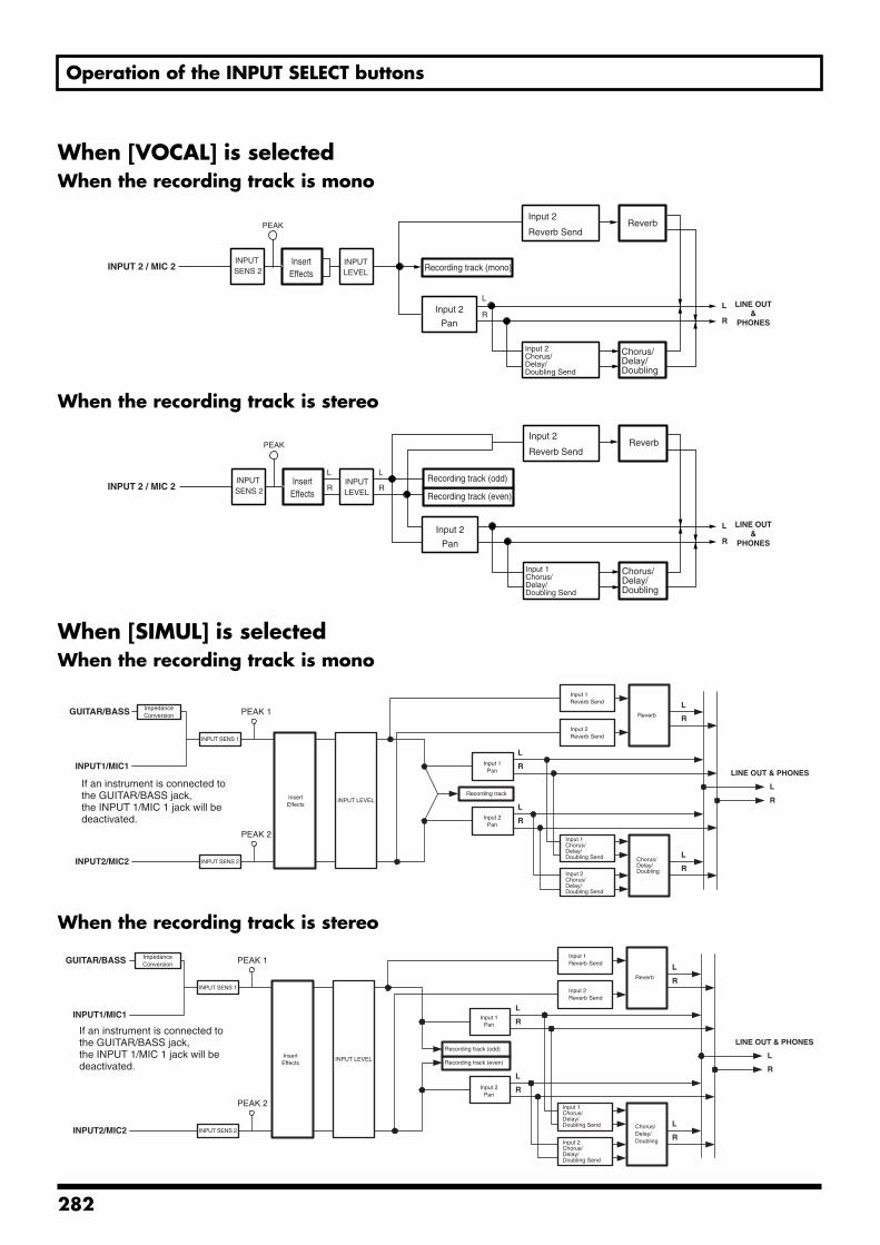
Operation of the INPUT SELECT buttons
When [VOCAL] is selectedWhen the recording track is monofig.92-03
When the recording track is stereofig.92-04
When [SIMUL] is selectedWhen the recording track is monofig.92-03
When the recording track is stereofig.92-04
Chorus/Delay/Doubling
LINE OUT&
PHONES
L
RInput 2
Pan
Reverb
INPUTLEVEL
InsertEffects
Recording track (mono)INPUT 2 / MIC 2INPUT
SENS 2
Input 2
Reverb SendPEAK
Input 2Chorus/Delay/Doubling Send
L
R
Chorus/Delay/Doubling
LINE OUT&
PHONES
L
RInput 2
Pan
Reverb
INPUTLEVEL
InsertEffects Recording track (even)
Recording track (odd)INPUT 2 / MIC 2
INPUT SENS 2
Input 2
Reverb Send
L
R
L
R
PEAK
Input 1Chorus/Delay/Doubling Send
GUITAR/BASS
INPUT1/MIC1
If an instrument is connected to the GUITAR/BASS jack, the INPUT 1/MIC 1 jack will be deactivated.
INPUT SENS 1
INPUT LEVEL
L
R
PEAK 1L
R
INPUT2/MIC2
PEAK 2
INPUT SENS 2
Recording track
L
R
L
R
L
R
Reverb
LINE OUT & PHONES
ImpedanceConversion
InsertEffects
Input 1Pan
Input 2Pan
Input 1Reverb Send
Input 2Reverb Send
Input 1Chorus/Delay/Doubling Send
Input 2Chorus/Delay/Doubling Send
Chorus/Delay/Doubling
GUITAR/BASS
INPUT1/MIC1
LINE OUT & PHONESIf an instrument is connected to the GUITAR/BASS jack, the INPUT 1/MIC 1 jack will be deactivated.
INPUT SENS 1
INPUT LEVELInsertEffects Recording track (even)
L
R
PEAK 1L
R
ImpedanceConversion
INPUT2/MIC2
PEAK 2
INPUT SENS 2
Recording track (odd)
L
R
L
R
L
R
Reverb
Input 1Pan
Input 2Pan
Input 1Reverb Send
Input 2Reverb Send
Input 1Chorus/Delay/Doubling Send
Input 2Chorus/Delay/Doubling Send
Chorus/Delay/Doubling
282
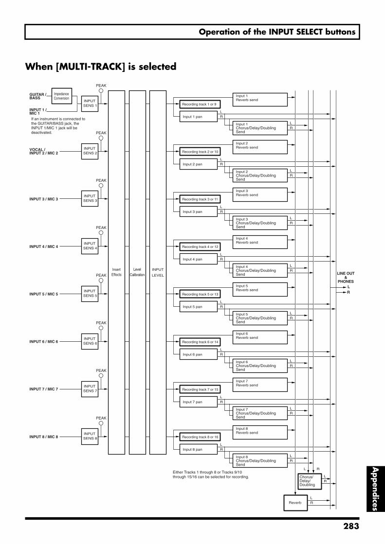
Operation of the INPUT SELECT buttons
Appendices
When [MULTI-TRACK] is selectedfig.92-05
Chorus/Delay/Doubling
LINE OUT&
PHONES
Reverb
Recording track 1 or 9
GUITAR / BASS
INPUT 1 /MIC 1
INPUT SENS 1
ImpedanceConversion
Input 1 pan
PEAK
LR
Input 1Reverb send
Input 1Chorus/Delay/DoublingSend
LR
Recording track 2 or 10VOCAL /INPUT 2 / MIC 2
INPUT SENS 2
Input 2 panLR
Input 2Reverb send
Input 2Chorus/Delay/DoublingSend
LR
Recording track 3 or 11INPUT 3 / MIC 3INPUT
SENS 3
Input 3 panLR
Input 3Reverb send
Input 3Chorus/Delay/DoublingSend
LR
Recording track 4 or 12INPUT 4 / MIC 4INPUT
SENS 4
Input 4 panLR
Input 4Reverb send
Input 4Chorus/Delay/DoublingSend
LR
Recording track 5 or 13INPUT 5 / MIC 5INPUT
SENS 5
Input 5 panLR
Input 5Reverb send
Input 5Chorus/Delay/DoublingSend
LR
Recording track 6 or 14INPUT 6 / MIC 6INPUT
SENS 6
Input 6 panLR
Input 6Reverb send
Input 6Chorus/Delay/DoublingSend
LR
Recording track 7 or 15INPUT 7 / MIC 7INPUT
SENS 7
Input 7 panLR
Input 7Reverb send
Input 7Chorus/Delay/DoublingSend
LR
Recording track 8 or 16INPUT 8 / MIC 8INPUT
SENS 8
Input 8 panLR
Input 8Reverb send
Input 8Chorus/Delay/DoublingSend
LR
INPUT
LEVEL
LevelCalibration
InsertEffects
L R
LR
LR
LR
Either Tracks 1 through 8 or Tracks 9/10 through 15/16 can be selected for recording.
PEAK
PEAK
PEAK
PEAK
PEAK
PEAK
PEAK
If an instrument is connected to the GUITAR/BASS jack, the INPUT 1/MIC 1 jack will be deactivated.
283
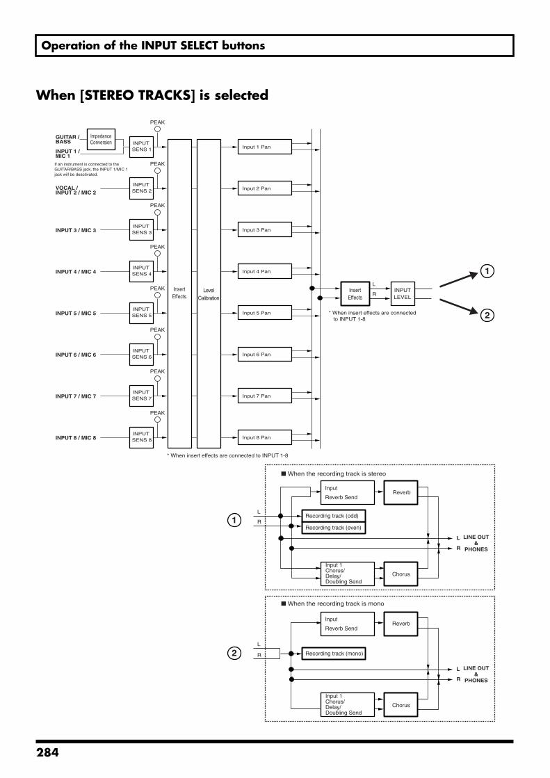
Operation of the INPUT SELECT buttons
When [STEREO TRACKS] is selectedfig.92-06
GUITAR / BASS
INPUT 1 /MIC 1
INPUT SENS 1
ImpedanceConversion
Input 1 Pan
PEAK
VOCAL /INPUT 2 / MIC 2
INPUT SENS 2 Input 2 Pan
PEAK
INPUT 3 / MIC 3INPUT
SENS 3 Input 3 Pan
PEAK
INPUT 4 / MIC 4INPUT
SENS 4 Input 4 Pan
PEAK
INPUT 5 / MIC 5INPUT
SENS 5 Input 5 Pan
PEAK
INPUT 6 / MIC 6INPUT
SENS 6 Input 6 Pan
PEAK
INPUT 7 / MIC 7INPUT
SENS 7 Input 7 Pan
PEAK
INPUT 8 / MIC 8INPUT
SENS 8 Input 8 Pan
PEAK
LevelCalibration
InsertEffects
INPUTLEVEL
InsertEffects
L
R
* When insert effects are connected to INPUT 1-8
* When insert effects are connected to INPUT 1-8
LINE OUT&
PHONES
L
R
Reverb
Chorus
Recording track (even)
Recording track (odd)
Input
Reverb Send
L
R
Input 1Chorus/Delay/Doubling Send
When the recording track is stereo
When the recording track is mono
LINE OUT&
PHONES
L
R
Reverb
Chorus
Recording track (mono)
Input
Reverb Send
L
R
Input 1Chorus/Delay/Doubling Send
1
2
1
2
If an instrument is connected to the GUITAR/BASS jack, the INPUT 1/MIC 1 jack will be deactivated.
284
REC MODE (Recording Mode) Operations
Appendices
The BR-1600CD offers three different recording modes, which you can choose from depending on the way in which you want to carry out recording.
INPUT mode:In this mode, input sources are recorded to tracks.
BOUNCE mode:In this mode, audio recorded on various tracks is mixed onto a stereo track.
MASTERING mode:In this mode, the volume and compression of songs recorded onto stereo tracks are adjusted in order to create CDs with higher levels of sound quality.
These three modes are referred to as Recording Modes.
By pressing [REC MODE] you can cycle through the choices for the recording mode, in this order:
INPUT → BOUNCE → MASTERING.
The currently selected recording mode can be determined by noticing which REC MODE indicator is lighted.
Input sources will be muted while recording modes are being changed. Note also that the mode selection is not possible while the BR-1600CD is playing or recording audio.
BR-1600CD operations in the various modes are as follows:
INPUTIn INPUT mode, input sources are recorded to tracks.
Although replay from other recorded tracks will be heard during recording, only the input sources will be recorded to the selected tracks.
Furthermore, when an insert effect is applied to the input sources, the mixture of the direct sound and the effected sound will be recorded. In contrast, the effected sound is not recorded in the case of loop effects, and only the direct sound is recorded.
BOUNCEIn BOUNCE mode, audio recorded on various tracks is mixed onto a stereo or mono track. (The term bounce or ping-pong is used to describe this type of operation.)
All track playback, rhythm guide performances, and other audio that can be heard via the LINE OUT jack or the PHONES 1 jack will be recorded to the selected track. As a result, moving the MASTER fader will cause the volume of the recorded audio to also change. If a metronome is being played, this too will be included in the recording, and the appropriate care should be taken.
All inputs are automatically muted during recording in BOUNCE mode. However, if an INPUT SELECT button is pressed at this time, muting for the corresponding input source(s) will be canceled, and its input audio will also be recorded together with the track playback.
MASTERINGIn MASTERING mode, the Mastering Tool Kit is applied to the audio recorded on Track 9/10, the volume and compression of this audio are adjusted, and it is re-recorded on the same track.
All input sources are muted in MASTERING mode, and this muting cannot be canceled. In addition, the rhythm guide and all tracks other than Track 9/10 are also muted at this time.
When recording is carried out, the audio from Track 9/10 is passed through the Mastering Tool Kit, and the resultant audio is recorded to a different V-Track on Track 9/10. This V-Track is marked as the final mastering track so that it may be easily recognized and selected when the mastered audio is to be written to a music CD later on.
Note that this mode has been provided as an addition to allow the volume and compression of audio tracks to be adjusted before they are written to music CDs. If you want to create music CDs that use the recorded tracks as they are, it will be sufficient to create a mixdown of these tracks onto a stereo track using BOUNCE mode, and there will be no need to use MASTERING mode. Accordingly, you can choose whether or not this mode is to be used.
285
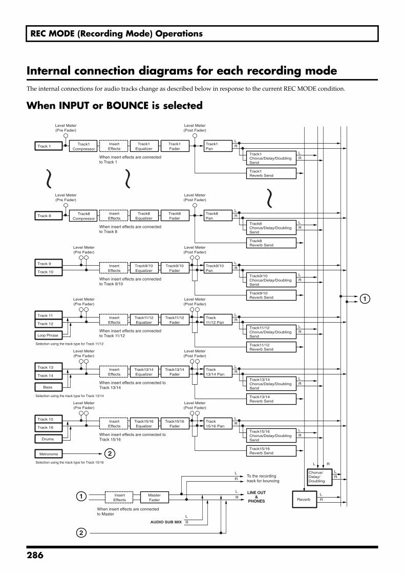
REC MODE (Recording Mode) Operations
Internal connection diagrams for each recording modeThe internal connections for audio tracks change as described below in response to the current REC MODE condition.
When INPUT or BOUNCE is selectedfig.93-01
Chorus/Delay/Doubling
LINE OUT&
PHONES Reverb
L R
LR
L
RLR
Track9/10Pan
Track9/10Fader
Track9/10Equalizer
InsertEffects
LR
Track9/10Chorus/Delay/DoublingSend
Track9/10Reverb Send
LR
Track 9
Track 10
Level Meter(Pre Fader)
Level Meter(Post Fader)
When insert effects are connected to Track 9/10
Track11/12 Pan
Track11/12Fader
Track11/12Equalizer
InsertEffects
LR
Track11/12Chorus/Delay/DoublingSend
Track11/12Reverb Send
LR
Track 11
Track 12
Loop Phrase
Level Meter(Pre Fader)
Level Meter(Post Fader)
When insert effects are connected to Track 11/12
Track13/14 Pan
Track13/14Fader
Track13/14Equalizer
InsertEffects
LR
Track13/14Chorus/Delay/DoublingSend
Track13/14Reverb Send
LR
Track 13
Track 14
Level Meter(Pre Fader)
Level Meter(Post Fader)
When insert effects are connected to Track 13/14
Track15/16 Pan
Track15/16Fader
Track15/16Equalizer
InsertEffects
LR
Track15/16Chorus/Delay/DoublingSend
Track15/16Reverb Send
LR
Track 15
Track 16
Level Meter(Pre Fader)
Level Meter(Post Fader)
When insert effects are connected to Track 15/16
Track1Pan
LR
Track1Chorus/Delay/DoublingSend
Track1Reverb Send
LR
Track 1
Level Meter(Pre Fader)
Level Meter(Post Fader)
When insert effects are connected to Track 1
Track1Fader
Track1Equalizer
InsertEffects
Track1Compressor
Track8Pan
LR
Track8Chorus/Delay/DoublingSend
Track8Reverb Send
LR
Track 8
Level Meter(Pre Fader)
Level Meter(Post Fader)
When insert effects are connected to Track 8
Track8Fader
Track8Equalizer
InsertEffects
Track8Compressor
Drums
Metronome
Bass
Selection using the track type for Track 11/12
Selection using the track type for Track 13/14
Selection using the track type for Track 15/16
1
1
2
MasterFader
InsertEffects
When insert effects are connected to Master
AUDIO SUB MIX
L
R
L
RTo the recording track for bouncing
2
286
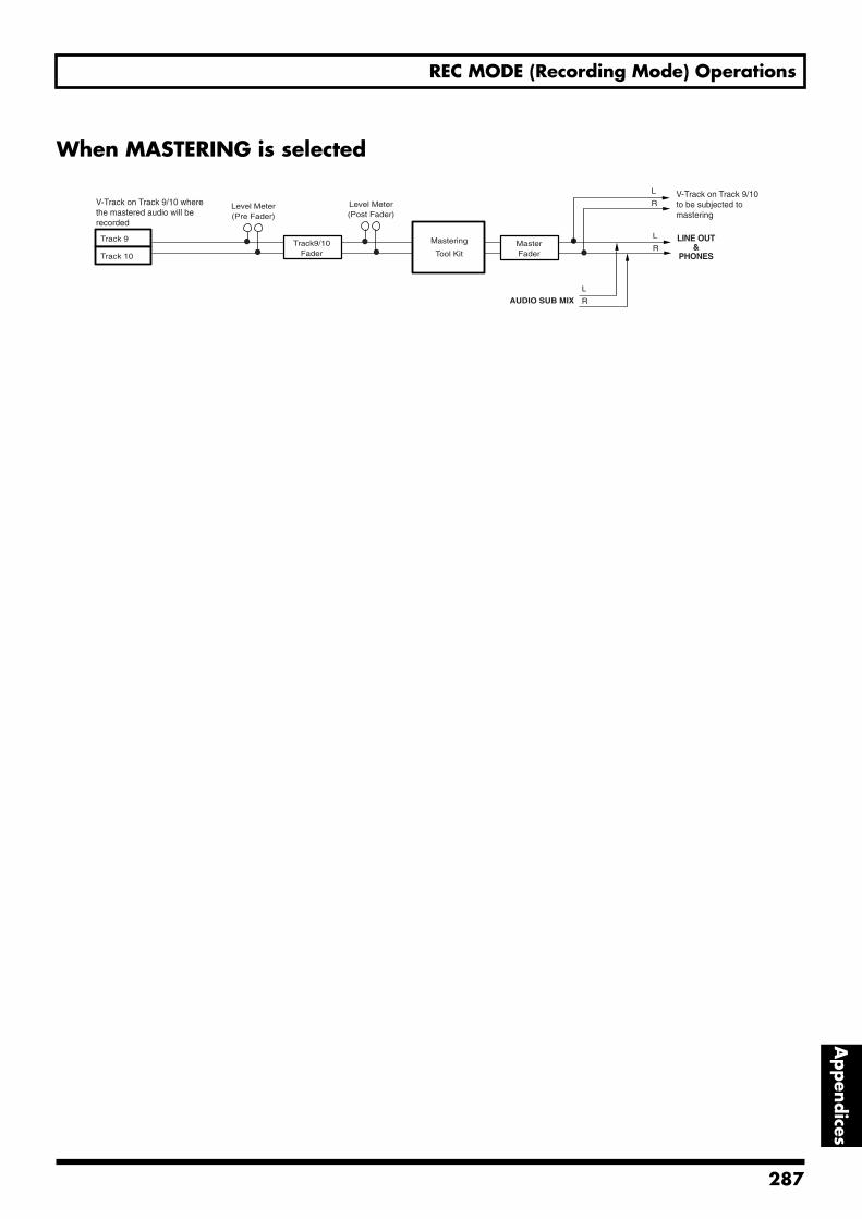
REC MODE (Recording Mode) Operations
Appendices
When MASTERING is selectedfig.93-02
LINE OUT&
PHONES
L
RMastering
Tool KitTrack9/10
Fader
Track 9
Track 10
Level Meter(Pre Fader)
Level Meter(Post Fader)
MasterFader
AUDIO SUB MIX
L
R
L
RV-Track on Track 9/10 to be subjected to mastering
V-Track on Track 9/10 where the mastered audio will be recorded
287
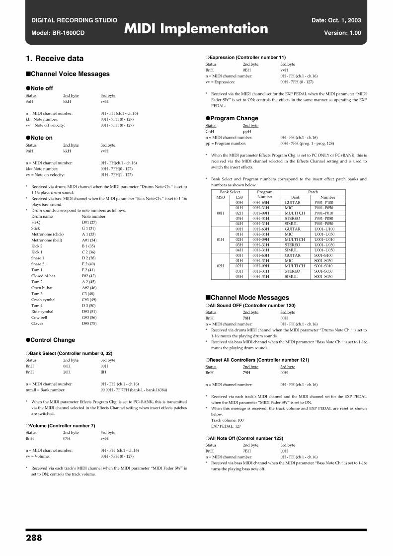
DIGITAL RECORDING STUDIO Date: Oct. 1, 2003
MIDI ImplementationModel: BR-1600CD Version: 1.00
1. Receive data
Channel Voice Messages
Note offStatus 2nd byte 3rd byte8nH kkH vvH
n = MIDI channel number: 0H - FH (ch.1 - ch.16)kk= Note number: 00H - 7FH (0 - 127)vv = Note off velocity: 00H - 7FH (0 - 127)
Note onStatus 2nd byte 3rd byte9nH kkH vvH
n = MIDI channel number: 0H - FH(ch.1 - ch.16)kk= Note number: 00H - 7FH(0 - 127)vv = Note on velocity: 01H - 7FH(1 - 127)
* Received via drums MIDI channel when the MIDI parameter “Drums Note Ch.” is set to1-16; plays drum sound.
* Received via bass MIDI channel when the MIDI parameter “Bass Note Ch.” is set to 1-16;plays bass sound.
* Drum sounds correspond to note numbers as follows.Drum name Note numberHi-Q D#1 (27)Stick G 1 (31)Metronome (click) A 1 (33)Metronome (bell) A#1 (34)Kick 2 B 1 (35)Kick 1 C 2 (36)Snare 1 D 2 (38)Snare 2 E 2 (40)Tom 1 F 2 (41)Closed hi-hat F#2 (42)Tom 2 A 2 (45)Open hi-hat A#2 (46)Tom 3 C3 (48)Crash cymbal C#3 (49)Tom 4 D 3 (50)Ride cymbal D#3 (51)Cow bell G#3 (56)Claves D#5 (75)
Control Change
Bank Select (Controller number 0, 32)Status 2nd byte 3rd byteBnH 00H 00HBnH 20H llH
n = MIDI channel number: 0H - FH (ch.1 - ch.16)mm,ll = Bank number: 00 00H - 7F 7FH (bank.1 - bank.16384)
* When the MIDI parameter Effects Program Chg. is set to PC+BANK, this is transmittedvia the MIDI channel selected in the Effects Channel setting when insert effects patchesare switched.
Volume (Controller number 7)Status 2nd byte 3rd byteBnH 07H vvH
n = MIDI channel number: 0H - FH (ch.1 - ch.16)vv = Volume: 00H - 7FH (0 - 127)
* Received via each track’s MIDI channel when the MIDI parameter “MIDI Fader SW” isset to ON; controls the track volume.
Expression (Controller number 11)Status 2nd byte 3rd byteBnH 0BH vvHn = MIDI channel number: 0H - FH (ch.1 - ch.16)vv = Expression: 00H - 7FH (0 - 127)
* Received via the MIDI channel set for the EXP PEDAL when the MIDI parameter “MIDIFader SW” is set to ON; controls the effects in the same manner as operating the EXPPEDAL.
Program ChangeStatus 2nd byteCnH ppHn = MIDI channel number: 0H - FH (ch.1 - ch.16)pp = Program number: 00H - 7FH (prog. 1 - prog. 128)
* When the MIDI parameter Effects Program Chg. is set to PC ONLY or PC+BANK, this isreceived via the MIDI channel selected in the Effects Channel setting and is used toswitch the insert effects.
* Bank Select and Program numbers correspond to the insert effect patch banks andnumbers as shown below.
Channel Mode MessagesAll Sound OFF (Controller number 120)Status 2nd byte 3rd byteBnH 78H 00Hn = MIDI channel number: 0H - FH (ch.1 - ch.16)* Received via drums MIDI channel when the MIDI parameter “Drums Note Ch.” is set to
1-16; mutes the playing drum sounds.* Received via bass MIDI channel when the MIDI parameter “Bass Note Ch.” is set to 1-16;
mutes the playing drum sounds.
Reset All Controllers (Controller number 121)Status 2nd byte 3rd byteBnH 79H 00H
n = MIDI channel number: 0H - FH (ch.1 - ch.16)
* Received via each track’s MIDI channel and the MIDI channel set for the EXP PEDALwhen the MIDI parameter “MIDI Fader SW” is set to ON.
* When this message is received, the track volume and EXP PEDAL are reset as shownbelow.Track volume: 100EXP PEDAL: 127
All Note Off (Control number 123)Status 2nd byte 3rd byteBnH 7BH 00Hn = MIDI channel number: 0H - FH (ch.1 - ch.16)* Received via bass MIDI channel when the MIDI parameter “Bass Note Ch.” is set to 1-16;
turns the playing bass note off.
Bank Select Program Number
PatchMSB LSB Bank Number
00H
00H 00H–63H GUITAR P001–P10001H 00H–31H MIC P001–P05002H 00H–09H MULTI CH P001–P01003H 00H–31H STEREO P001–P05004H 00H–31H SIMUL P001–P050
01H
00H 00H–63H GUITAR U001–U10001H 00H–31H MIC U001–U05002H 00H–09H MULTI CH U001–U01003H 00H–31H STEREO U001–U05004H 00H–31H SIMUL U001–U050
02H
00H 00H–63H GUITAR S001–S10001H 00H–31H MIC S001–S05002H 00H–09H MULTI CH S001–S01003H 00H–31H STEREO S001–S05004H 00H–31H SIMUL S001–S050
288
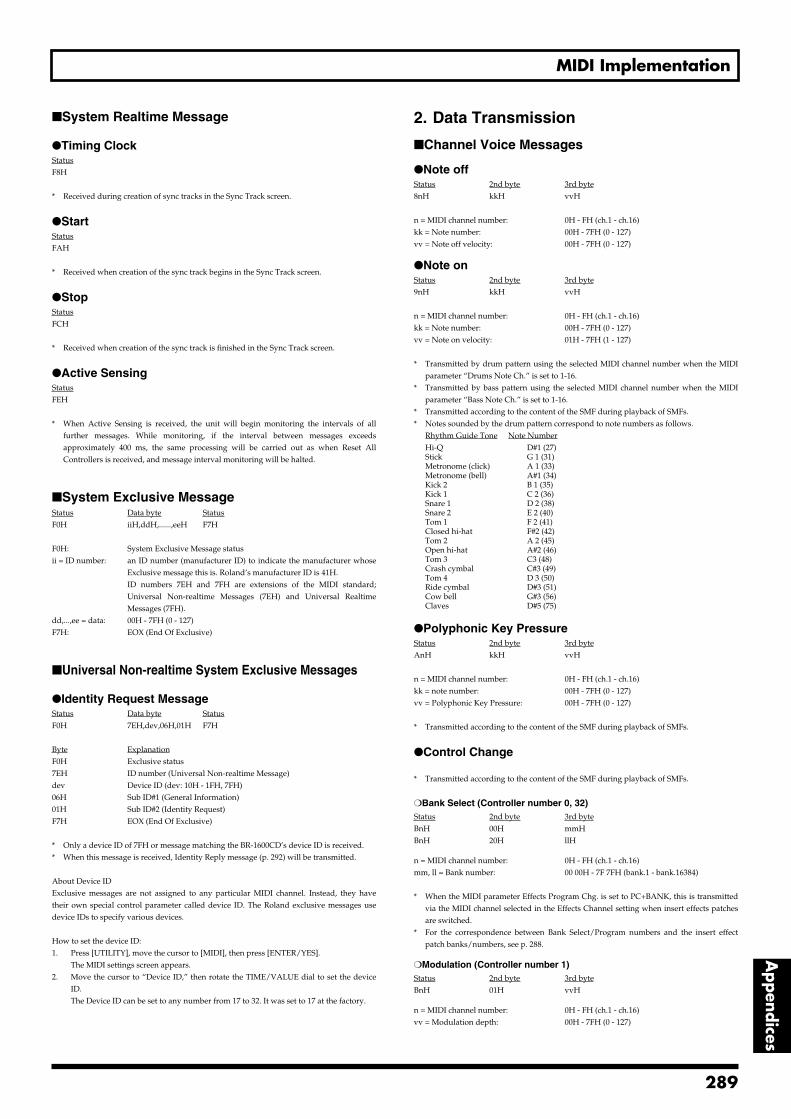
MIDI Implementation
Appendices
System Realtime Message
Timing ClockStatusF8H
* Received during creation of sync tracks in the Sync Track screen.
StartStatusFAH
* Received when creation of the sync track begins in the Sync Track screen.
StopStatusFCH
* Received when creation of the sync track is finished in the Sync Track screen.
Active SensingStatusFEH
* When Active Sensing is received, the unit will begin monitoring the intervals of allfurther messages. While monitoring, if the interval between messages exceedsapproximately 400 ms, the same processing will be carried out as when Reset AllControllers is received, and message interval monitoring will be halted.
System Exclusive MessageStatus Data byte StatusF0H iiH,ddH,......,eeH F7H
F0H: System Exclusive Message statusii = ID number: an ID number (manufacturer ID) to indicate the manufacturer whose
Exclusive message this is. Roland’s manufacturer ID is 41H.ID numbers 7EH and 7FH are extensions of the MIDI standard;Universal Non-realtime Messages (7EH) and Universal RealtimeMessages (7FH).
dd,...,ee = data: 00H - 7FH (0 - 127)F7H: EOX (End Of Exclusive)
Universal Non-realtime System Exclusive Messages
Identity Request MessageStatus Data byte StatusF0H 7EH,dev,06H,01H F7H
Byte ExplanationF0H Exclusive status7EH ID number (Universal Non-realtime Message)dev Device ID (dev: 10H - 1FH, 7FH)06H Sub ID#1 (General Information)01H Sub ID#2 (Identity Request)F7H EOX (End Of Exclusive)
* Only a device ID of 7FH or message matching the BR-1600CD’s device ID is received.* When this message is received, Identity Reply message (p. 292) will be transmitted.
About Device IDExclusive messages are not assigned to any particular MIDI channel. Instead, they havetheir own special control parameter called device ID. The Roland exclusive messages usedevice IDs to specify various devices.
How to set the device ID:1. Press [UTILITY], move the cursor to [MIDI], then press [ENTER/YES].
The MIDI settings screen appears.2. Move the cursor to “Device ID,” then rotate the TIME/VALUE dial to set the device
ID.The Device ID can be set to any number from 17 to 32. It was set to 17 at the factory.
2. Data Transmission
Channel Voice Messages
Note offStatus 2nd byte 3rd byte8nH kkH vvH
n = MIDI channel number: 0H - FH (ch.1 - ch.16)kk = Note number: 00H - 7FH (0 - 127)vv = Note off velocity: 00H - 7FH (0 - 127)
Note onStatus 2nd byte 3rd byte9nH kkH vvH
n = MIDI channel number: 0H - FH (ch.1 - ch.16)kk = Note number: 00H - 7FH (0 - 127)vv = Note on velocity: 01H - 7FH (1 - 127)
* Transmitted by drum pattern using the selected MIDI channel number when the MIDIparameter “Drums Note Ch.” is set to 1-16.
* Transmitted by bass pattern using the selected MIDI channel number when the MIDIparameter “Bass Note Ch.” is set to 1-16.
* Transmitted according to the content of the SMF during playback of SMFs.* Notes sounded by the drum pattern correspond to note numbers as follows.
Rhythm Guide Tone Note NumberHi-Q D#1 (27)Stick G 1 (31)Metronome (click) A 1 (33)Metronome (bell) A#1 (34)Kick 2 B 1 (35)Kick 1 C 2 (36)Snare 1 D 2 (38)Snare 2 E 2 (40)Tom 1 F 2 (41)Closed hi-hat F#2 (42)Tom 2 A 2 (45)Open hi-hat A#2 (46)Tom 3 C3 (48)Crash cymbal C#3 (49)Tom 4 D 3 (50)Ride cymbal D#3 (51)Cow bell G#3 (56)Claves D#5 (75)
Polyphonic Key PressureStatus 2nd byte 3rd byteAnH kkH vvH
n = MIDI channel number: 0H - FH (ch.1 - ch.16)kk = note number: 00H - 7FH (0 - 127)vv = Polyphonic Key Pressure: 00H - 7FH (0 - 127)
* Transmitted according to the content of the SMF during playback of SMFs.
Control Change
* Transmitted according to the content of the SMF during playback of SMFs.
Bank Select (Controller number 0, 32)Status 2nd byte 3rd byteBnH 00H mmHBnH 20H llH
n = MIDI channel number: 0H - FH (ch.1 - ch.16)mm, ll = Bank number: 00 00H - 7F 7FH (bank.1 - bank.16384)
* When the MIDI parameter Effects Program Chg. is set to PC+BANK, this is transmittedvia the MIDI channel selected in the Effects Channel setting when insert effects patchesare switched.
* For the correspondence between Bank Select/Program numbers and the insert effectpatch banks/numbers, see p. 288.
Modulation (Controller number 1)Status 2nd byte 3rd byteBnH 01H vvH
n = MIDI channel number: 0H - FH (ch.1 - ch.16)vv = Modulation depth: 00H - 7FH (0 - 127)
289
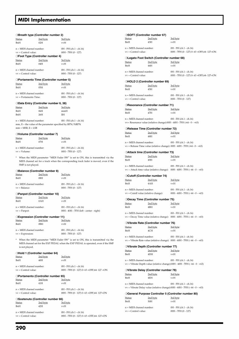
MIDI Implementation
Breath type (Controller number 2)Status 2nd byte 3rd byteBnH 02H vvH
n = MIDI channel number: 0H - FH (ch.1 - ch.16)vv = Control value: 00H - 7FH (0 - 127)
Foot Type (Controller number 4)Status 2nd byte 3rd byteBnH 04H vvH
n = MIDI channel number: 0H - FH (ch.1 - ch.16)vv = Control value: 00H - 7FH (0 - 127)
Portamento Time (Controller number 5)Status 2nd byte 3rd byteBnH 05H vvH
n = MIDI channel number: 0H - FH (ch.1 - ch.16)vv = Portamento Time: 00H - 7FH (0 - 127)
Data Entry (Controller number 6, 38)Status 2nd byte 3rd byteBnH 06H mmHBnH 26H llH
n = MIDI channel number: 0H - FH (ch.1 - ch.16)mm, ll = the value of the parameter specified by RPN/NRPNmm = MSB, ll = LSB
Volume (Controller number 7)Status 2nd byte 3rd byteBnH 07H vvH
n = MIDI channel number: 0H - FH (ch.1 - ch.16)vv = Volume: 00H - 7FH (0 - 127)
* When the MIDI parameter “MIDI Fader SW” is set to ON, this is transmitted via theMIDI channel set for a track when the corresponding track fader is moved, even if theSMF is not played.
Balance (Controller number 8)Status 2nd byte 3rd byteBnH 08H vvH
n = MIDI channel number: 0H - FH (ch.1 - ch.16)vv = Balance: 00H - 7FH (0 - 127)
Panpot (Controller number 10)Status 2nd byte 3rd byteBnH 0AH vvH
n = MIDI channel number: 0H - FH (ch.1 - ch.16)vv = Panpot: 00H - 40H - 7FH (left - center - right)
Expression (Controller number 11)Status 2nd byte 3rd byteBnH 0BH vvH
n = MIDI channel number: 0H - FH (ch.1 - ch.16)vv = Expression: 00H - 7FH (0 - 127)
* When the MIDI parameter “MIDI Fader SW” is set to ON, this is transmitted via theMIDI channel set for the EXP PEDAL when the EXP PEDAL is operated, even if the SMFis not played.
Hold 1 (Controller number 64)Status 2nd byte 3rd byteBnH 40H vvH
n = MIDI channel number: 0H - FH (ch.1 - ch.16)vv = Control value: 00H - 7FH (0 - 127) 0- 63 =OFF,64- 127 =ON
Portamento (Controller number 65)Status 2nd byte 3rd byteBnH 41H vvH
n = MIDI channel number: 0H - FH (ch.1 - ch.16)vv = Control value: 00H - 7FH (0 - 127) 0- 63 =OFF,64- 127=ON
Sostenuto (Controller number 66) Status 2nd byte 3rd byteBnH 42H vvH
n = MIDI channel number: 0H - FH (ch.1 - ch.16)vv = Control value: 00H - 7FH (0 - 127) 0- 63 =OFF,64- 127=ON
SOFT (Controller number 67)Status 2nd byte 3rd byteBnH 43H vvH
n = MIDI channel number: 0H - FH (ch.1 - ch.16)vv = Control value: 00H - 7FH (0 - 127) 0- 63 =OFF,64- 127=ON
Legato Foot Switch (Controller number 68)Status 2nd byte 3rd byteBnH 44H vvH
n = MIDI channel number: 0H - FH (ch.1 - ch.16)vv = Control value: 00H - 7FH (0 - 127) 0- 63 =OFF,64- 127=ON
HOLD 2 (Controller number 69)Status 2nd byte 3rd byteBnH 45H vvH
n = MIDI channel number: 0H - FH (ch.1 - ch.16)vv = Control value: 00H - 7FH (0 - 127)
Resonance (Controller number 71)Status 2nd byte 3rd byteBnH 47H vvH
n = MIDI channel number: 0H - FH (ch.1 - ch.16)vv= Resonance value (relative change):00H - 40H - 7FH (-64 - 0 - +63)
Release Time (Controller number 72)Status 2nd byte 3rd byteBnH 48H vvH
n = MIDI channel number: 0H - FH (ch.1 - ch.16)vv = Release Time value (relative change): 00H - 40H - 7FH (-64 - 0 - +63)
Attack time (Controller number 73)Status 2nd byte 3rd byteBnH 49H vvH
n = MIDI channel number: 0H - FH (ch.1 - ch.16)vv = Attack time value (relative change): 00H - 40H - 7FH (- 64 - 0 - +63)
Cutoff (Controller number 74)Status 2nd byte 3rd byteBnH 4AH vvH
n = MIDI channel number: 0H - FH (ch.1 - ch.16)vv = Cutoff value (relative change): 00H - 40H - 7FH (- 64 - 0 - +63)
Decay Time (Controller number 75)Status 2nd byte 3rd byteBnH 4BH vvH
n = MIDI channel number: 0H - FH (ch.1 - ch.16)vv = Decay Time value (relative change): 00H - 40H - 7FH (- 64 - 0 - +63)
Vibrate Rate (Controller number 76)Status 2nd byte 3rd byteBnH 4CH vvH
n = MIDI channel number: 0H - FH (ch.1 - ch.16)vv = Vibrate Rate value (relative change): 00H - 40H - 7FH (- 64 - 0 - +63)
Vibrate Depth (Controller number 77)Status 2nd byte 3rd byteBnH 4DH vvH
n = MIDI channel number: 0H - FH (ch.1 - ch.16)vv = Vibrate Depth value (relative change):00H - 40H - 7FH (- 64 - 0 - +63)
Vibrate Delay (Controller number 78)Status 2nd byte 3rd byteBnH 4EH vvH
n = MIDI channel number: 0H - FH (ch.1 - ch.16)vv = Vibrate Delay value (relative change):00H - 40H - 7FH (- 64 - 0 - +63)
General Purpose Controller 5 (Controller number 80)Status 2nd byte 3rd byteBnH 50H vvH
n = MIDI channel number: 0H - FH (ch.1 - ch.16)vv = Control value: 00H - 7FH (0 - 127)
290
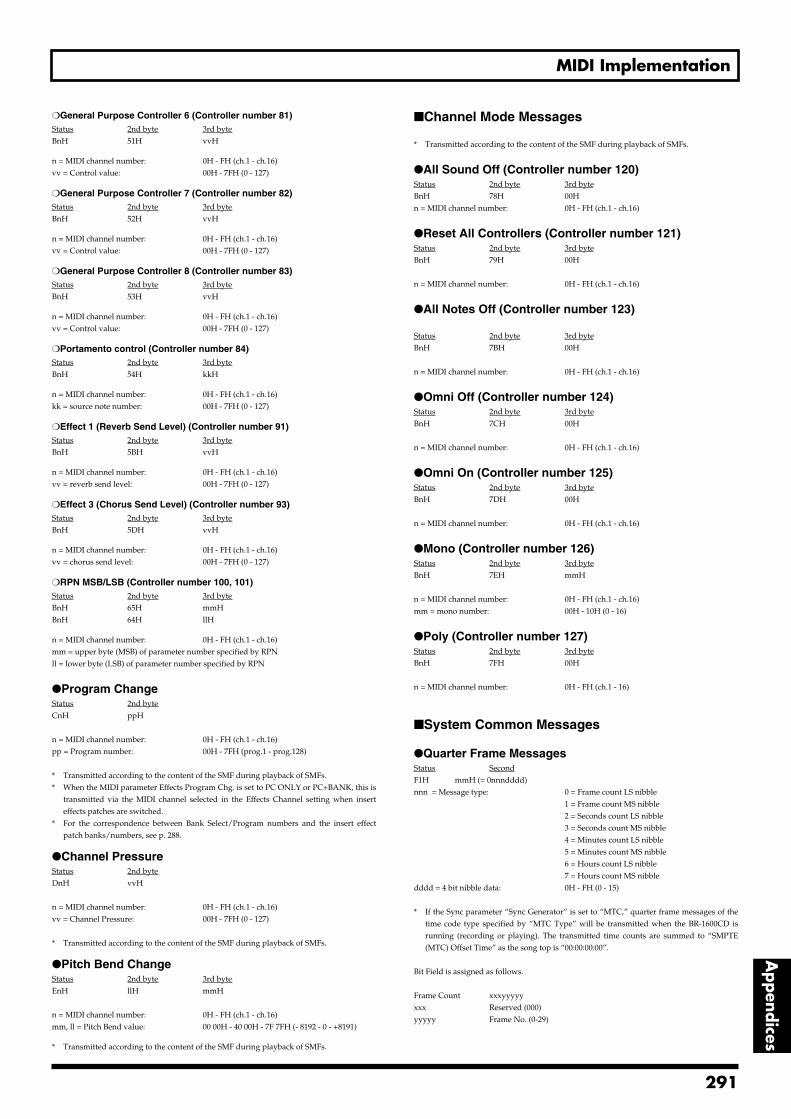
MIDI Implementation
Appendices
General Purpose Controller 6 (Controller number 81)Status 2nd byte 3rd byteBnH 51H vvH
n = MIDI channel number: 0H - FH (ch.1 - ch.16)vv = Control value: 00H - 7FH (0 - 127)
General Purpose Controller 7 (Controller number 82)Status 2nd byte 3rd byteBnH 52H vvH
n = MIDI channel number: 0H - FH (ch.1 - ch.16)vv = Control value: 00H - 7FH (0 - 127)
General Purpose Controller 8 (Controller number 83)Status 2nd byte 3rd byteBnH 53H vvH
n = MIDI channel number: 0H - FH (ch.1 - ch.16)vv = Control value: 00H - 7FH (0 - 127)
Portamento control (Controller number 84)Status 2nd byte 3rd byteBnH 54H kkH
n = MIDI channel number: 0H - FH (ch.1 - ch.16)kk = source note number: 00H - 7FH (0 - 127)
Effect 1 (Reverb Send Level) (Controller number 91)Status 2nd byte 3rd byteBnH 5BH vvH
n = MIDI channel number: 0H - FH (ch.1 - ch.16)vv = reverb send level: 00H - 7FH (0 - 127)
Effect 3 (Chorus Send Level) (Controller number 93)Status 2nd byte 3rd byteBnH 5DH vvH
n = MIDI channel number: 0H - FH (ch.1 - ch.16)vv = chorus send level: 00H - 7FH (0 - 127)
RPN MSB/LSB (Controller number 100, 101)Status 2nd byte 3rd byteBnH 65H mmHBnH 64H llH
n = MIDI channel number: 0H - FH (ch.1 - ch.16)mm = upper byte (MSB) of parameter number specified by RPNll = lower byte (LSB) of parameter number specified by RPN
Program ChangeStatus 2nd byteCnH ppH
n = MIDI channel number: 0H - FH (ch.1 - ch.16)pp = Program number: 00H - 7FH (prog.1 - prog.128)
* Transmitted according to the content of the SMF during playback of SMFs.* When the MIDI parameter Effects Program Chg. is set to PC ONLY or PC+BANK, this is
transmitted via the MIDI channel selected in the Effects Channel setting when inserteffects patches are switched.
* For the correspondence between Bank Select/Program numbers and the insert effectpatch banks/numbers, see p. 288.
Channel PressureStatus 2nd byteDnH vvH
n = MIDI channel number: 0H - FH (ch.1 - ch.16)vv = Channel Pressure: 00H - 7FH (0 - 127)
* Transmitted according to the content of the SMF during playback of SMFs.
Pitch Bend ChangeStatus 2nd byte 3rd byteEnH llH mmH
n = MIDI channel number: 0H - FH (ch.1 - ch.16)mm, ll = Pitch Bend value: 00 00H - 40 00H - 7F 7FH (- 8192 - 0 - +8191)
* Transmitted according to the content of the SMF during playback of SMFs.
Channel Mode Messages
* Transmitted according to the content of the SMF during playback of SMFs.
All Sound Off (Controller number 120)Status 2nd byte 3rd byteBnH 78H 00Hn = MIDI channel number: 0H - FH (ch.1 - ch.16)
Reset All Controllers (Controller number 121)Status 2nd byte 3rd byteBnH 79H 00H
n = MIDI channel number: 0H - FH (ch.1 - ch.16)
All Notes Off (Controller number 123)
Status 2nd byte 3rd byteBnH 7BH 00H
n = MIDI channel number: 0H - FH (ch.1 - ch.16)
Omni Off (Controller number 124)Status 2nd byte 3rd byteBnH 7CH 00H
n = MIDI channel number: 0H - FH (ch.1 - ch.16)
Omni On (Controller number 125)Status 2nd byte 3rd byteBnH 7DH 00H
n = MIDI channel number: 0H - FH (ch.1 - ch.16)
Mono (Controller number 126)Status 2nd byte 3rd byteBnH 7EH mmH
n = MIDI channel number: 0H - FH (ch.1 - ch.16)mm = mono number: 00H - 10H (0 - 16)
Poly (Controller number 127)Status 2nd byte 3rd byteBnH 7FH 00H
n = MIDI channel number: 0H - FH (ch.1 - 16)
System Common Messages
Quarter Frame MessagesStatus SecondF1H mmH (= 0nnndddd)nnn = Message type: 0 = Frame count LS nibble
1 = Frame count MS nibble2 = Seconds count LS nibble3 = Seconds count MS nibble4 = Minutes count LS nibble5 = Minutes count MS nibble6 = Hours count LS nibble7 = Hours count MS nibble
dddd = 4 bit nibble data: 0H - FH (0 - 15)
* If the Sync parameter “Sync Generator” is set to “MTC,” quarter frame messages of thetime code type specified by “MTC Type” will be transmitted when the BR-1600CD isrunning (recording or playing). The transmitted time counts are summed to “SMPTE(MTC) Offset Time” as the song top is “00:00:00:00”.
Bit Field is assigned as follows.
Frame Count xxxyyyyyxxx Reserved (000)yyyyy Frame No. (0-29)
291
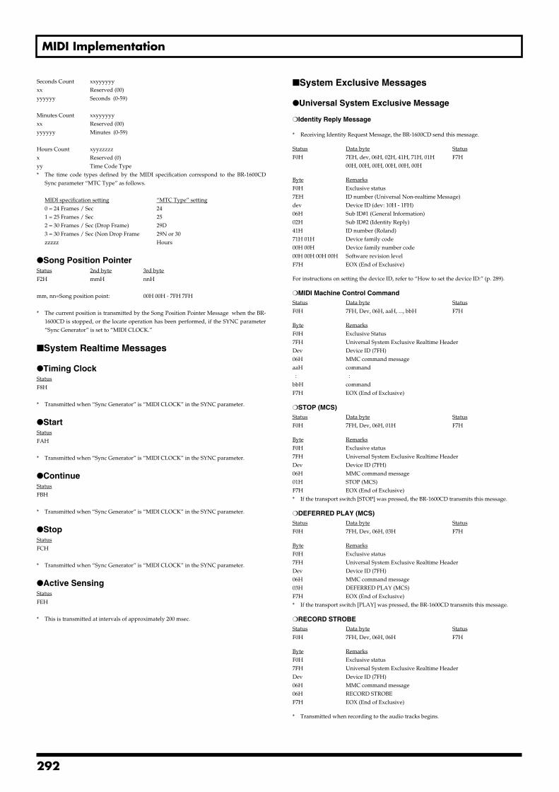
MIDI Implementation
Seconds Count xxyyyyyyxx Reserved (00)yyyyyy Seconds (0-59)
Minutes Count xxyyyyyyxx Reserved (00)yyyyyy Minutes (0-59)
Hours Count xyyzzzzzx Reserved (0)yy Time Code Type* The time code types defined by the MIDI specification correspond to the BR-1600CD
Sync parameter “MTC Type” as follows.
MIDI specification setting “MTC Type” setting0 = 24 Frames / Sec 241 = 25 Frames / Sec 252 = 30 Frames / Sec (Drop Frame) 29D3 = 30 Frames / Sec (Non Drop Frame 29N or 30zzzzz Hours
Song Position PointerStatus 2nd byte 3rd byteF2H mmH nnH
mm, nn=Song position point: 00H 00H - 7FH 7FH
* The current position is transmitted by the Song Position Pointer Message when the BR-1600CD is stopped, or the locate operation has been performed, if the SYNC parameter“Sync Generator” is set to “MIDI CLOCK.”
System Realtime Messages
Timing ClockStatusF8H
* Transmitted when “Sync Generator” is “MIDI CLOCK” in the SYNC parameter.
StartStatusFAH
* Transmitted when “Sync Generator” is “MIDI CLOCK” in the SYNC parameter.
ContinueStatusFBH
* Transmitted when “Sync Generator” is “MIDI CLOCK” in the SYNC parameter.
StopStatusFCH
* Transmitted when “Sync Generator” is “MIDI CLOCK” in the SYNC parameter.
Active SensingStatusFEH
* This is transmitted at intervals of approximately 200 msec.
System Exclusive Messages
Universal System Exclusive Message
Identity Reply Message
* Receiving Identity Request Message, the BR-1600CD send this message.
Status Data byte StatusF0H 7EH, dev, 06H, 02H, 41H, 71H, 01H F7H
00H, 00H, 00H, 00H, 00H, 00H
Byte RemarksF0H Exclusive status7EH ID number (Universal Non-realtime Message)dev Device ID (dev: 10H - 1FH)06H Sub ID#1 (General Information)02H Sub ID#2 (Identity Reply)41H ID number (Roland)71H 01H Device family code00H 00H Device family number code00H 00H 00H 00H Software revision levelF7H EOX (End of Exclusive)
For instructions on setting the device ID, refer to “How to set the device ID:” (p. 289).
MIDI Machine Control CommandStatus Data byte StatusF0H 7FH, Dev, 06H, aaH, ..., bbH F7H
Byte RemarksF0H Exclusive Status7FH Universal System Exclusive Realtime HeaderDev Device ID (7FH)06H MMC command messageaaH command : :bbH commandF7H EOX (End of Exclusive)
STOP (MCS)Status Data byte StatusF0H 7FH, Dev, 06H, 01H F7H
Byte RemarksF0H Exclusive status7FH Universal System Exclusive Realtime HeaderDev Device ID (7FH)06H MMC command message01H STOP (MCS)F7H EOX (End of Exclusive)* If the transport switch [STOP] was pressed, the BR-1600CD transmits this message.
DEFERRED PLAY (MCS)Status Data byte StatusF0H 7FH, Dev, 06H, 03H F7H
Byte RemarksF0H Exclusive status7FH Universal System Exclusive Realtime HeaderDev Device ID (7FH)06H MMC command message03H DEFERRED PLAY (MCS)F7H EOX (End of Exclusive)* If the transport switch [PLAY] was pressed, the BR-1600CD transmits this message.
RECORD STROBEStatus Data byte StatusF0H 7FH, Dev, 06H, 06H F7H
Byte RemarksF0H Exclusive status7FH Universal System Exclusive Realtime HeaderDev Device ID (7FH)06H MMC command message06H RECORD STROBEF7H EOX (End of Exclusive)
* Transmitted when recording to the audio tracks begins.
292
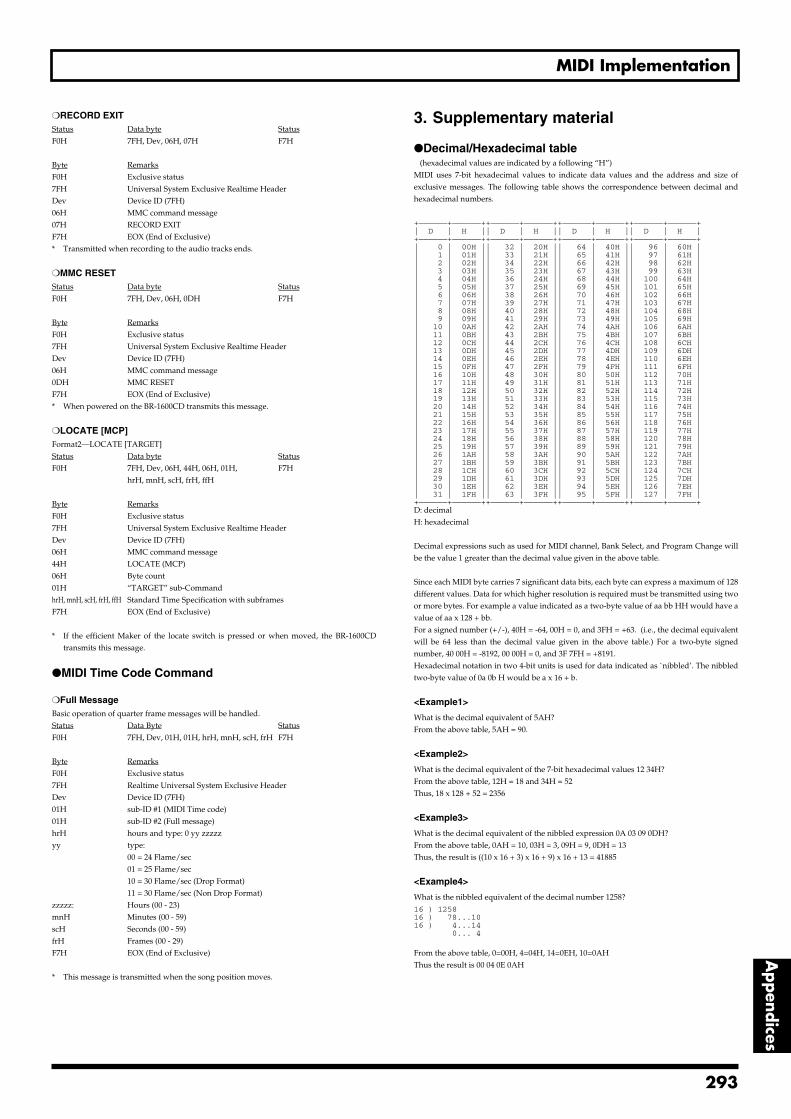
MIDI Implementation
Appendices
RECORD EXITStatus Data byte StatusF0H 7FH, Dev, 06H, 07H F7H
Byte RemarksF0H Exclusive status7FH Universal System Exclusive Realtime HeaderDev Device ID (7FH)06H MMC command message07H RECORD EXITF7H EOX (End of Exclusive)* Transmitted when recording to the audio tracks ends.
MMC RESETStatus Data byte StatusF0H 7FH, Dev, 06H, 0DH F7H
Byte RemarksF0H Exclusive status7FH Universal System Exclusive Realtime HeaderDev Device ID (7FH)06H MMC command message0DH MMC RESETF7H EOX (End of Exclusive)* When powered on the BR-1600CD transmits this message.
LOCATE [MCP]Format2—LOCATE [TARGET]Status Data byte StatusF0H 7FH, Dev, 06H, 44H, 06H, 01H, F7H
hrH, mnH, scH, frH, ffH
Byte RemarksF0H Exclusive status7FH Universal System Exclusive Realtime HeaderDev Device ID (7FH)06H MMC command message44H LOCATE (MCP)06H Byte count01H “TARGET” sub-CommandhrH, mnH, scH, frH, ffH Standard Time Specification with subframesF7H EOX (End of Exclusive)
* If the efficient Maker of the locate switch is pressed or when moved, the BR-1600CDtransmits this message.
MIDI Time Code Command
Full MessageBasic operation of quarter frame messages will be handled.Status Data Byte StatusF0H 7FH, Dev, 01H, 01H, hrH, mnH, scH, frH F7H
Byte RemarksF0H Exclusive status7FH Realtime Universal System Exclusive HeaderDev Device ID (7FH)01H sub-ID #1 (MIDI Time code)01H sub-ID #2 (Full message)hrH hours and type: 0 yy zzzzzyy type:
00 = 24 Flame/sec01 = 25 Flame/sec10 = 30 Flame/sec (Drop Format)11 = 30 Flame/sec (Non Drop Format)
zzzzz: Hours (00 - 23)mnH Minutes (00 - 59)scH Seconds (00 - 59)frH Frames (00 - 29)F7H EOX (End of Exclusive)
* This message is transmitted when the song position moves.
3. Supplementary material
Decimal/Hexadecimal table (hexadecimal values are indicated by a following “H”)MIDI uses 7-bit hexadecimal values to indicate data values and the address and size ofexclusive messages. The following table shows the correspondence between decimal andhexadecimal numbers.
+——————+——————++——————+——————++——————+——————++——————+——————+| D | H || D | H || D | H || D | H |+——————+——————++——————+——————++——————+——————++——————+——————+| 0 | 00H || 32 | 20H || 64 | 40H || 96 | 60H || 1 | 01H || 33 | 21H || 65 | 41H || 97 | 61H || 2 | 02H || 34 | 22H || 66 | 42H || 98 | 62H || 3 | 03H || 35 | 23H || 67 | 43H || 99 | 63H || 4 | 04H || 36 | 24H || 68 | 44H || 100 | 64H || 5 | 05H || 37 | 25H || 69 | 45H || 101 | 65H || 6 | 06H || 38 | 26H || 70 | 46H || 102 | 66H || 7 | 07H || 39 | 27H || 71 | 47H || 103 | 67H || 8 | 08H || 40 | 28H || 72 | 48H || 104 | 68H || 9 | 09H || 41 | 29H || 73 | 49H || 105 | 69H || 10 | 0AH || 42 | 2AH || 74 | 4AH || 106 | 6AH || 11 | 0BH || 43 | 2BH || 75 | 4BH || 107 | 6BH || 12 | 0CH || 44 | 2CH || 76 | 4CH || 108 | 6CH || 13 | 0DH || 45 | 2DH || 77 | 4DH || 109 | 6DH || 14 | 0EH || 46 | 2EH || 78 | 4EH || 110 | 6EH || 15 | 0FH || 47 | 2FH || 79 | 4FH || 111 | 6FH || 16 | 10H || 48 | 30H || 80 | 50H || 112 | 70H || 17 | 11H || 49 | 31H || 81 | 51H || 113 | 71H || 18 | 12H || 50 | 32H || 82 | 52H || 114 | 72H || 19 | 13H || 51 | 33H || 83 | 53H || 115 | 73H || 20 | 14H || 52 | 34H || 84 | 54H || 116 | 74H || 21 | 15H || 53 | 35H || 85 | 55H || 117 | 75H || 22 | 16H || 54 | 36H || 86 | 56H || 118 | 76H || 23 | 17H || 55 | 37H || 87 | 57H || 119 | 77H || 24 | 18H || 56 | 38H || 88 | 58H || 120 | 78H || 25 | 19H || 57 | 39H || 89 | 59H || 121 | 79H || 26 | 1AH || 58 | 3AH || 90 | 5AH || 122 | 7AH || 27 | 1BH || 59 | 3BH || 91 | 5BH || 123 | 7BH || 28 | 1CH || 60 | 3CH || 92 | 5CH || 124 | 7CH || 29 | 1DH || 61 | 3DH || 93 | 5DH || 125 | 7DH || 30 | 1EH || 62 | 3EH || 94 | 5EH || 126 | 7EH || 31 | 1FH || 63 | 3FH || 95 | 5FH || 127 | 7FH |+——————+——————++——————+——————++——————+——————++——————+——————+D: decimalH: hexadecimal
Decimal expressions such as used for MIDI channel, Bank Select, and Program Change willbe the value 1 greater than the decimal value given in the above table.
Since each MIDI byte carries 7 significant data bits, each byte can express a maximum of 128different values. Data for which higher resolution is required must be transmitted using twoor more bytes. For example a value indicated as a two-byte value of aa bb HH would have avalue of aa x 128 + bb.For a signed number (+/-), 40H = -64, 00H = 0, and 3FH = +63. (i.e., the decimal equivalentwill be 64 less than the decimal value given in the above table.) For a two-byte signednumber, 40 00H = -8192, 00 00H = 0, and 3F 7FH = +8191.Hexadecimal notation in two 4-bit units is used for data indicated as `nibbled’. The nibbledtwo-byte value of 0a 0b H would be a x 16 + b.
<Example1>
What is the decimal equivalent of 5AH?From the above table, 5AH = 90.
<Example2>
What is the decimal equivalent of the 7-bit hexadecimal values 12 34H?From the above table, 12H = 18 and 34H = 52Thus, 18 x 128 + 52 = 2356
<Example3>
What is the decimal equivalent of the nibbled expression 0A 03 09 0DH?From the above table, 0AH = 10, 03H = 3, 09H = 9, 0DH = 13Thus, the result is ((10 x 16 + 3) x 16 + 9) x 16 + 13 = 41885
<Example4>
What is the nibbled equivalent of the decimal number 1258?16 ) 125816 ) 78...1016 ) 4...14 0... 4
From the above table, 0=00H, 4=04H, 14=0EH, 10=0AHThus the result is 00 04 0E 0AH
293
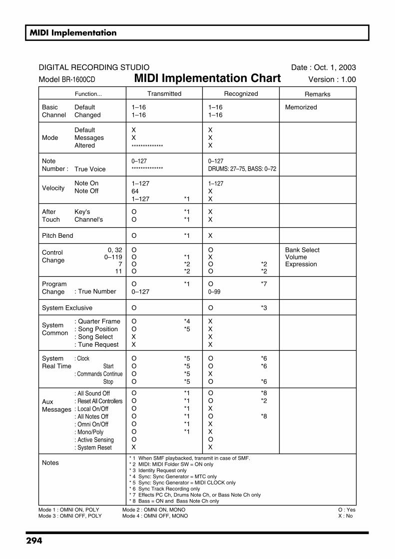
MIDI Implementation
MIDI Implementation Chart
Function...
BasicChannel
Mode
NoteNumber :
Velocity
AfterTouch
Pitch Bend
ControlChange
ProgramChange
System Exclusive
SystemCommon
SystemReal Time
AuxMessages
Notes
Transmitted Recognized Remarks
DefaultChanged
DefaultMessagesAltered
True Voice
Note OnNote Off
Key'sChannel's
0, 320–119
711
: True Number
: Quarter Frame: Song Position: Song Select: Tune Request
: Clock
: CommandsStartContinueStop
: All Sound Off: Reset All Controllers: Local On/Off: All Notes Off: Omni On/Off: Mono/Poly: Active Sensing: System Reset
1–161–16
XX
1–127641–127 *1
0–127
OO
*1*1
O *1
OOOO
*1*2*2
OXOO
O0–127
*1
O
OOXX
*4*5
OOOO
*5*5*5*5
OOOOOOOX
*1*1*1*1*1*1
1–161–16
Memorized
XXX
1–127XX
0–127DRUMS: 27–75, BASS: 0–72
XX
X
O0–99
O *3
*7
XXXX
OOXO
*6*6
*6
OOXOXXOX
*8*2
*8
* 1 When SMF playbacked, transmit in case of SMF.* 2 MIDI: MIDI Folder SW = ON only* 3 Identity Request only* 4 Sync: Sync Generator = MTC only* 5 Sync: Sync Generator = MIDI CLOCK only* 6 Sync Track Recording only* 7 Effects PC Ch, Drums Note Ch, or Bass Note Ch only* 8 Bass = ON and Bass Note Ch only
DIGITAL RECORDING STUDIO
Model BR-1600CD
Date : Oct. 1, 2003
Version : 1.00MIDI Implementation Chart
**************
**************
Mode 1 : OMNI ON, POLYMode 3 : OMNI OFF, POLY
Mode 2 : OMNI ON, MONOMode 4 : OMNI OFF, MONO
O : YesX : No
*2*2
Bank SelectVolumeExpression
294
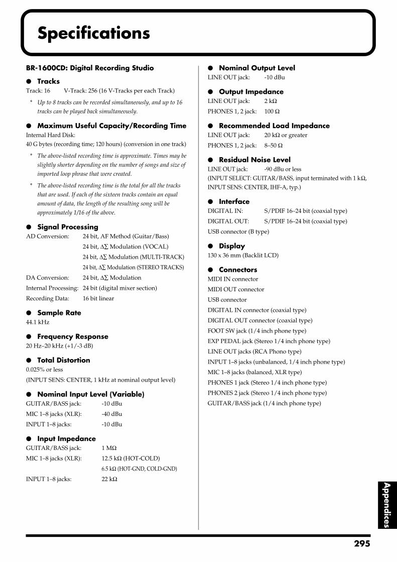
Specifications
Appendices
BR-1600CD: Digital Recording Studio
TracksTrack: 16 V-Track: 256 (16 V-Tracks per each Track)
* Up to 8 tracks can be recorded simultaneously, and up to 16
tracks can be played back simultaneously.
Maximum Useful Capacity/Recording TimeInternal Hard Disk:40 G bytes (recording time; 120 hours) (conversion in one track)
* The above-listed recording time is approximate. Times may be
slightly shorter depending on the number of songs and size of
imported loop phrase that were created.
* The above-listed recording time is the total for all the tracks
that are used. If each of the sixteen tracks contain an equal
amount of data, the length of the resulting song will be
approximately 1/16 of the above.
Signal ProcessingAD Conversion: 24 bit, AF Method (Guitar/Bass)
24 bit, ∆∑ Modulation (VOCAL)
24 bit, ∆∑ Modulation (MULTI-TRACK)
24 bit, ∆∑ Modulation (STEREO TRACKS)
DA Conversion: 24 bit, ∆∑ Modulation
Internal Processing: 24 bit (digital mixer section)
Recording Data: 16 bit linear
Sample Rate44.1 kHz
Frequency Response20 Hz–20 kHz (+1/-3 dB)
Total Distortion0.025% or less
(INPUT SENS: CENTER, 1 kHz at nominal output level)
Nominal Input Level (Variable)GUITAR/BASS jack: -10 dBu
MIC 1–8 jacks (XLR): -40 dBu
INPUT 1–8 jacks: -10 dBu
Input ImpedanceGUITAR/BASS jack: 1 MΩ
MIC 1–8 jacks (XLR): 12.5 kΩ (HOT-COLD)
6.5 kΩ (HOT-GND, COLD-GND)
INPUT 1–8 jacks: 22 kΩ
Nominal Output LevelLINE OUT jack: -10 dBu
Output ImpedanceLINE OUT jack: 2 kΩ
PHONES 1, 2 jack: 100 Ω
Recommended Load ImpedanceLINE OUT jack: 20 kΩ or greater
PHONES 1, 2 jack: 8–50 Ω
Residual Noise LevelLINE OUT jack: -90 dBu or less(INPUT SELECT: GUITAR/BASS, input terminated with 1 kΩ, INPUT SENS: CENTER, IHF-A, typ.)
InterfaceDIGITAL IN: S/PDIF 16–24 bit (coaxial type)
DIGITAL OUT: S/PDIF 16–24 bit (coaxial type)
USB connector (B type)
Display130 x 36 mm (Backlit LCD)
ConnectorsMIDI IN connector
MIDI OUT connector
USB connector
DIGITAL IN connector (coaxial type)
DIGITAL OUT connector (coaxial type)
FOOT SW jack (1/4 inch phone type)
EXP PEDAL jack (Stereo 1/4 inch phone type)
LINE OUT jacks (RCA Phono type)
INPUT 1–8 jacks (unbalanced, 1/4 inch phone type)
MIC 1–8 jacks (balanced, XLR type)
PHONES 1 jack (Stereo 1/4 inch phone type)
PHONES 2 jack (Stereo 1/4 inch phone type)
GUITAR/BASS jack (1/4 inch phone type)
295
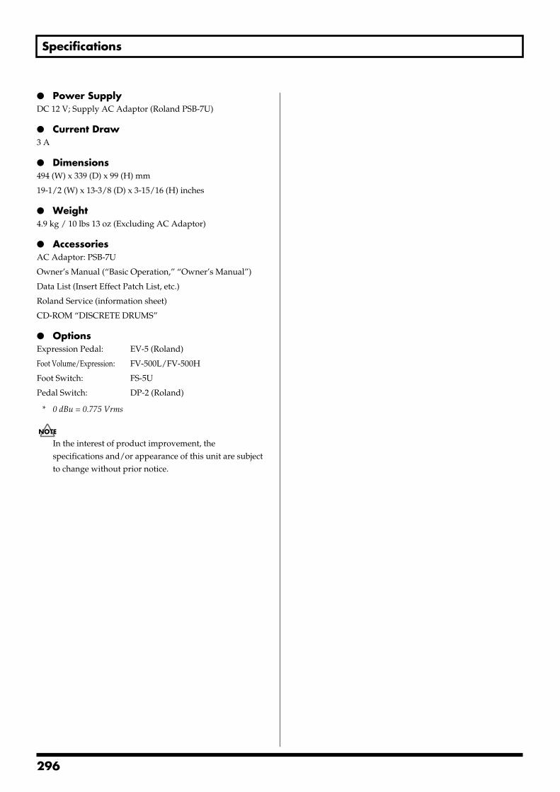
Specifications
Power SupplyDC 12 V; Supply AC Adaptor (Roland PSB-7U)
Current Draw3 A
Dimensions494 (W) x 339 (D) x 99 (H) mm
19-1/2 (W) x 13-3/8 (D) x 3-15/16 (H) inches
Weight4.9 kg / 10 lbs 13 oz (Excluding AC Adaptor)
AccessoriesAC Adaptor: PSB-7U
Owner’s Manual (“Basic Operation,” “Owner’s Manual”)
Data List (Insert Effect Patch List, etc.)
Roland Service (information sheet)
CD-ROM “DISCRETE DRUMS”
OptionsExpression Pedal: EV-5 (Roland)
Foot Volume/Expression: FV-500L/FV-500H
Foot Switch: FS-5U
Pedal Switch: DP-2 (Roland)
* 0 dBu = 0.775 Vrms
In the interest of product improvement, the specifications and/or appearance of this unit are subject to change without prior notice.
296
Index
Symbols*TMP .................... 78, 121, 125, 130, 152, 166, 177, 179, 189*TMP(CURRENT) .......................... 81–82, 121, 125–126, 131+ ............................................................ 57, 59, 62–63, 194, 211=>COPY ......................................................................... 160, 173=>DELETE ............................................................ 161, 174, 197=>PRM. ........................................................... 78, 120, 124, 130
Numerics123... ........................................................................................... 8112STAGE ................................................................................. 1011-PEDAL ................................................................................. 1021-VOICE .................................................................................. 1021x10” .......................................................................................... 961x12” .......................................................................................... 962-MONO ................................................................................. 1022-ST (2-stereo) ........................................................................ 1022x12” .......................................................................................... 962x2 Chorus ......................................................................... 85, 923 Band Equalizer ...................................................................... 913Band Equalizer ....................................................................... 894 Band Equalizer ...................................................................... 914Band Equalizer ................................................................ 85–894Band Equalizer/Wah ..................................................... 86–884STAGE ................................................................................... 1014x12” .......................................................................................... 965150DRV ................................................................................... 9560S FUZ ..................................................................................... 947STRING ................................................................................. 1068CH COMP EQ ........................................................................ 898STAGE ................................................................................... 1018x12” .......................................................................................... 96
AA<=>a ....................................................................................... 81ABSOLUTE TIME .................................................................. 228AC ................................................................................... 103–104ac .............................................................................................. 104ACC ....................................................................... 157, 169–170Accent ...................................................................................... 169Access indicator ....................................................................... 30ACOUSTIC GUITAR .............................................................. 86Acoustic Guitar Simulator ........................................ 85, 89–90Acoustic Processor ..................................................... 86, 89–90ACOUSTIC SIM ....................................................................... 85Adjusting chorus ................................................................... 114Adjusting delay ...................................................................... 114Adjusting doubling ............................................................... 115Adjusting reverb .................................................................... 113AF method ................................................................................ 24AIFF ............................................................... 180, 212, 248, 250AIFF file .................................................................................. 210AKGC3K ................................................................................. 100
Algorithm .......................................................................... 77, 85ALL ........................................................................ 181, 185, 208ALL icon ................................................................................. 268Amb Density ............................................................................ 96Amb HF Damp ........................................................................ 96Amb Level ................................................................................ 96Amb Pre-Dly ............................................................................ 96Amb Size ................................................................................... 96Ambience .................................................................................. 96AMERCAN ............................................................................... 94AMG ............................................................................... 103–104amg .......................................................................................... 104Amp Type ............................................................................... 103ARRANGEMENT .................................................................. 209Arrangement mode ............................................................... 148Arrangement/Drums&Bass Pattern ................................... 206ARRANGEMENT/DRUMS/BASS/LOOP PHRASE ...... 209ARRANGEMENT/PATTERN ................................... 148, 187ARRANGEMENT/PATTERN button ................................. 28ATTACK ................................................................................. 109Attack ............................................................ 93–94, 96, 99, 136Attack Time .............................................................................. 94AUDIO ................................................... 27, 149, 163, 176, 200Audio CD creation ................................................................ 216Audio CD import ................................................................... 219Audio CD import screen ...................................................... 219Audio CD screen .......................................................... 216, 219Audio CD Write screen ......................................................... 216AUDIO CD WRITE/PLAY .................................................. 216AUDIO CD WRITE/PLAY button ....................................... 29Audio level ............................................................................. 237AUDIO LVL ........................................................................... 237Audio sub mix ........................................................................ 266AUDIO TRACK MIXER faders 1–8, 9/10–15/16 ............... 27AUTO FADE ................................................................. 132–133AUTO FADE IN ..................................................................... 132Auto Fade In setting screen .................................................. 132Auto Fade In/Out ................................................................. 132AUTO FADE OUT ................................................................. 133Auto Fade Out setting screen .............................................. 133AUTO PUNCH [ON/OFF] .................................................... 44AUTO PUNCH IN/OUT ....................................................... 26Auto punch in/out .................................................................. 43AUTO PUNCH IN/OUT [IN] ............................................... 43AUTO PUNCH IN/OUT [OUT] ........................................... 43Auto Scene ................................................................... 50, 52–53Auto wah ................................................................................ 106AW .................................................................................. 106–107
297
Index
BBack up ........................................................................................ 6Backing chorus ....................................................................... 119BACKUP ........................................................................ 204, 242Backup ..................................................................................... 204Backup screen ........................................................................ 204Balance .................................................................................... 121BANK
GUITAR .............................................................................. 85MIC ...................................................................................... 87MULTI-CHANNEL .......................................................... 89SIMUL ................................................................................. 88
Bank .................................................................................... 76–77BASS ............................................................................... 163, 189Bass ........................................................... 94–95, 103, 146, 163Bass Cut Filter .................................................. 88, 92, 128, 135BASS MULTI ............................................................................ 86Bass pattern ................................................................... 146, 164BASS SIM .................................................................................. 85Bass Simulator ................................................................... 85, 92Bass sound .............................................................................. 164Bass Tone ................................................................................ 164BD-2 ........................................................................................... 94BEAT .............................................................................. 183, 199Beat .................................................................. 38, 186, 198–199BEAT MAP ............................................................................. 199Beat map ........................................................................ 198–199Beat Map screen ..................................................................... 199BEEP ........................................................................................ 201BG DRV ..................................................................................... 95BG LEAD ......................................................................... 95, 103BG RHY ..................................................................................... 95BG STK .................................................................................... 104bg stk ....................................................................................... 104BIPHASE ................................................................................. 101Bit ............................................................................................... 99BLOCK<= ............................................................... 78, 125, 130BLUES .............................................................................. 95, 103BLUES OD ................................................................................ 94Body ........................................................................................... 90BoomBox ................................................................................. 127BoomLoB ................................................................................ 127BOOSTER ................................................................................. 94BOSSCmp ................................................................................. 94BOTTOM ................................................................................ 192BOUNCE .......................................................................... 25, 285BPF .................................................................................. 100, 107BPM ...................................................... 151, 153, 167, 178, 188BR-1600CD icon ..................................................................... 241BRIGHT ............................................................................ 96, 113Bright ................................................................................ 95, 103BRIGHTNESS ......................................................................... 237Brightness ............................................................................... 237BUTTON ASSIGN ................................................................. 184BY TRACK .............................................................................. 179
CCALCULATE ......................................................................... 258CANCEL ................................................................................... 79CD Hold Time ........................................................................ 215CD hold time .......................................................................... 215CD player ................................................................................ 216CD Track ................................................................................... 49CD-R disc .................................................................................... 7CD-R/RW ........................................................................ 29, 203CD-R/RW disc ........................................................................... 7
Compatibility ....................................................................... 8Inserting ................................................................................ 8Precautions ........................................................................... 7Removing ............................................................................. 8
CD-R/RW drive .............................................................. 30, 275CD-R/RW drive’s internal motor ....................................... 215CD-RW disc ................................................................................ 7CD-RW erase .......................................................................... 217CENTER ........................................................................... 96, 104Character ............................................................................ 90, 92Chord ....................................................................................... 165
Deleting ............................................................................. 191Inputting ........................................................................... 190Inserting ............................................................................ 191
Chord input screen ................................................................ 190CHORD MAP ......................................................................... 190Chord progression ........................................................ 148, 190Chord specifications .............................................................. 165Chord type .............................................................................. 190CHORUS ................................................................................. 114Chorus .................................................... 74, 85, 87–88, 92, 112Chorus Edit ............................................................................. 114Chorus Send ........................................................................... 121CHORUS/DELAY button .................................... 27, 114–115Chorus/Delay Edit screen .................................................... 114CLEAN .................................................................................... 103CLEANTW ............................................................................... 95CLEAR ALL .................................................................. 189, 193CLEAR button ................................................................... 25, 48CLICK ...................................................................................... 201Clip .......................................................................................... 236CmpH Attack ......................................................................... 136CmpH Ratio ........................................................................... 136CmpH Release ........................................................................ 136CmpH Thres ........................................................................... 136CmpL Attack .......................................................................... 136CmpL Ratio ............................................................................ 136CmpL Release ........................................................................ 136CmpL Thres ............................................................................ 136CmpM Attack ......................................................................... 136CmpM Ratio ........................................................................... 136CmpM Release ....................................................................... 136CmpM Thres .......................................................................... 136COLOR CB ............................................................................. 237Color Cb .................................................................................. 237
298
Index
COLOR CR ............................................................................. 237Color Cr ................................................................................... 237Color difference signal .......................................................... 237COMMON .............................................................................. 120COMP button .................................................................. 27, 109Compatible OS ....................................................................... 240Compressor ................................... 74, 85, 88–89, 93, 108, 136Compressor Edit screen ........................................................ 109Compressor screen ................................................................ 109Compressor/Defretter ..................................................... 85–86Condenser microphone ........................................................ 264Connecting V-LINK devices ................................................ 236Connectors ................................................................................ 35Control Surface ........................................................................ 24Copy
Bass pattern ...................................................................... 173Drum pattern ................................................................... 160Loop phrase ..................................................................... 184Rhythm arrangement ..................................................... 196
COPY + INS icon ..................................................................... 57COPY icon ................................................................. 56, 68, 184Copying .............................................................................. 56, 82Copyright ........................................................................... 5, 219Cord hook ................................................................................. 32COSM ........................................................................................ 74COSM BASS AMP ................................................................... 86COSM COMP BASS AMP ...................................................... 87COSM COMP GUITAR AMP ................................................ 86COSM Comp/Limiter ................................................ 86–87, 94COSM OD GUITAR AMP ...................................................... 85COSM Overdrive/Distortion ......................................... 85, 94COSM PreAmp&Speaker ................................................ 85, 95COSM VOCAL COMP ........................................................... 87Create By Track screen ......................................................... 179CRUNCH ......................................................................... 95, 103CRY WAH .............................................................................. 106CS ............................................................................................... 93Current position ...................................................................... 38Cursor ........................................................................................ 39CURSOR buttons ..................................................................... 29CURVE ........................................................................... 132–133CUT icon ................................................................................... 62Cut Off Freq ................................................................... 128, 135Cutoff Freq .............................................................................. 100
DD:E Balance ...................................................................... 99, 102DARK ............................................................................... 96, 113Data CD screen ...................................................................... 204DATA SAVE/LOAD ............................................................ 204DATA SAVE/LOAD button .................................................. 29DC IN (AC adaptor) jack ................................................. 32, 37D-Comp .................................................................................... 94De-esser .............................................................................. 87, 96DEFAULT ...................................................................... 113–115
Defretter ....................................................................... 85–86, 96DELAY .................................................................................... 114Delay .............................................................. 75, 85–89, 97, 112Delay Time ............................................................. 97, 104, 135Delay time ............................................................................... 114DELAY TYPE ......................................................................... 115DELETE ......................................... 81, 158, 171, 189, 191, 193Delete
Bass pattern ...................................................................... 174Drum pattern ................................................................... 161
DELETE button ................................................................. 26, 43Delete screen for drum patterns .......................................... 161Deleting ..................................................................................... 62DENSITY ................................................................................ 113DEPTH .................................................................................... 114Depth .................................................. 92, 96, 98, 101, 105–107Detect HPF ................................................................................ 99DIGITAL ................................................................................... 99Digital copy ............................................................................ 262Digital Copy Protect .............................................................. 262Digital In Assign .................................................................... 261DIGITAL IN connector ............................................ 32, 35, 261DIGITAL OUT connector ................................................ 32, 36Direct Level ..................................... 96, 98, 100–102, 104, 106Disc At Once By Marker ......................................................... 49Disc tray .................................................................................... 30Disk Initialize ......................................................................... 270Disk memory used for the song ............................................ 67DISP.FMT. .................... 57, 59, 61, 63–64, 180, 194, 211, 252Display ...................................................................................... 31DISSOLVE .............................................................................. 237Dissolve time .......................................................................... 237Distance .............................................................................. 88, 97DISTORT ................................................................................... 94Dither ....................................................................................... 136DIV ........................................................................................... 270DOUBLING ............................................................................ 115Doubling ................................................ 75, 85, 87–88, 97, 112Doubling effect ......................................................................... 97DOWN .................................................................................... 107DR-20 ....................................................................................... 100Drive .......................................................................................... 94Drive Busy! ............................................................................. 193Driver ...................................................................................... 240Drop format ............................................................................ 227Drum Kit ........................................................................ 150, 156Drum pattern ....................................................... 146, 150, 152DRUM&BASS PATTERN ..................................................... 209DRUMS ................................................................. 149, 189, 200Drums ............................................................................. 146, 149Drums Note Channel ............................................................ 223DRV STK ................................................................................... 95DS-30A ........................................................................... 123, 127DS-50A .................................................................................... 127DS-90A .................................................................................... 127
299

Index
DST+ .......................................................................................... 94DUAL STREAM ..................................................................... 237Dual stream ............................................................................ 237DV-7PR ................................................................................... 236Dynamic microphone ........................................................... 264
EEDIT ........................................................................................... 77EDIT button .............................................................................. 28EDITED ..................................................................................... 67Editing ....................................................................................... 56Effect block ............................................................. 77, 123, 129Effect block connection ........................................................... 79Effect Level ........................................ 92, 96–98, 100–101, 104Effect Level1 ........................................................................... 106Effect Level2 ........................................................................... 106Effect On/Off .................................... 90–92, 94–106, 134–136Effect Patch ............................................................................... 76Effect Patch Copy .................................................................... 82Effect Patch Write .................................................................... 81Effect Type .............................................................................. 106EFFECTS ................................................................................. 208Effects ............................................................................... 74, 206EFFECTS button ............................................................... 25, 77Effects Channel ...................................................................... 235Effects Edit screen .................................................................... 77EFFECTS icon ......................................................................... 268Effects Location screen ........................................................... 82Effects Patch screen ................................................................. 77Effects Patch Write/Copy screen .......................................... 81Effects Program Change ....................................................... 235Effects Program Chg. ............................................................ 235Eight times as fast ................................................ 205–207, 212Eject ............................................................... 242, 245, 249, 253EJECT button ............................................................................ 30Electric condenser microphone ........................................... 265Emergency eject hole .............................................................. 30END (End point) ........................ 57, 59, 63–64, 180, 194, 211ENHANCE ............................................................................... 90Enhancer ............................................................. 86–87, 98, 135ENTER/YES button ................................................................ 29EQ button ......................................................................... 27, 110Equalizer ................................................................. 74, 108, 134Equalizer Edit screen ............................................................ 110Equalizer screen ..................................................................... 110Equalizer/Wah ........................................................................ 85ERASE ................................................................... 189, 193, 238Erase
CD-RW disc ............................................................. 214, 217Loop phrase ..................................................................... 185
ERASE icon .............................................. 63, 69, 185, 214, 217ERASE OFF .................................................................... 153, 167ERASE ON ..................................................................... 153, 167Erasing ...................................................................................... 63Error message ......................................................................... 277
EV-5 ........................................................................................... 84EXCHANGE icon .................................................................... 60Exchanging ............................................................................... 60EXIT/NO button ..................................................................... 29EXP Pedal Channel ................................................................ 233EXP PEDAL jack ............................................................... 33, 84Expander ................................................................................. 135ExpH Attack ........................................................................... 135ExpH Ratio ............................................................................. 135ExpH Release ......................................................................... 135ExpH Thres ............................................................................. 135ExpL Attack ............................................................................ 135ExpL Ratio .............................................................................. 135ExpL Release .......................................................................... 135ExpL Thres .............................................................................. 135ExpM Attack ........................................................................... 135ExpM Ratio ............................................................................. 135ExpM Release ......................................................................... 135ExpM Thres ............................................................................ 135Expression pedal ............................................................. 84, 274Extension ................................................................................ 252
FFade in ..................................................................................... 132Fade-out .................................................................................. 132FADER icon ............................................................................ 233Fader position ........................................................................ 233FAST ........................................................................................ 102FAT .......................................................................................... 106FAT MCH ................................................................................. 95FEEDBACK ............................................................................ 114Feedback ................................................................. 97, 102, 104FF button ................................................................................... 26Filter ........................................................................................... 99Final Mastering Track ...................................................... 46–47FINALIZE ............................................................................... 218Finalize .................................................................................... 218Fine .......................................................................................... 102FL ............................................................................................... 98Flanger .................................................................. 85, 87–88, 98Flanging effect .......................................................................... 98Flashing green .......................................................................... 27Flashing orange ........................................................................ 27Flashing orange and green ..................................................... 27Flashing red .............................................................................. 27Flat .................................................................................... 97, 100FOOT SW jack .......................................................................... 33Foot switch ............................................................................... 43Foot Volume ...................................................................... 85–88Foot Volume On/Off .............................................................. 98Formant ................................................................................... 106Formant1 ................................................................................. 106Formant2 ................................................................................. 106Four times as fast ................................................. 205–207, 212Frame ................................................................................ 38, 227
300
Index
Frames ....................................................................................... 31Freq ..................................................................................... 92, 99Frequency .............................................. 98, 104, 107, 128, 135Fretless bass .............................................................................. 96FROM ...................................... 81–82, 121–122, 125–126, 131FROM (From point) ......................................................... 57, 59Front Panel ............................................................................... 34FULLRNG ................................................................................. 95FUNCTION buttons ................................................................ 38FX ............................................................................................... 85
GGain ................................................................. 95, 100, 103, 128Gain SW .................................................................................... 95GATE ..................................................................... 157, 169, 171Gate time ................................................................................. 169GLOBAL icon ......................................................................... 267GM ......................................................................... 162, 175, 223Ground terminal ...................................................................... 33GS ........................................................................... 162, 175, 223Guitar bank ............................................................................... 76GUITAR/BASS ............................................................... 24, 280GUITAR/BASS effects ............................................................ 74GUITAR/BASS jack ......................................................... 34–35GUV DS ..................................................................................... 94
HH TO HF ................................................................................. 101H TO S ..................................................................................... 101HALL ....................................................................................... 113HARD ............................................................................... 93, 109Hard disk ........................................................................... 6, 275
Emergency ............................................................................ 6Precaution ............................................................................ 6Setup ..................................................................................... 6
Hard disk capacity .................................................................. 70Hard Disk Information ......................................................... 269Hard Disk screen ................................................................... 269Harmony Sequence ............................................... 75, 116, 119Harmony Sequence edit screen ........................................... 120HD ACCESS indicator ............................................................ 29HDD backup .......................................................................... 206HDD icon .............................................................. 207, 209, 269HDD recover .......................................................................... 209Hed.Dy .................................................................................... 100HF DAMP ...................................................................... 113–114Hi Cut Freq ........................................................................ 92, 97HI.FEML ........................................................................ 118, 121HI.MALE ....................................................................... 118, 121HIGH .............................................................................. 103, 110High Depth ............................................................................... 93High Freq ......................................................................... 91, 134High Freq Trimmer ............................................................... 128HIGH FREQUENCY ............................................................. 111
HIGH GAIN ........................................................................... 111High Gain ............................................................... 91, 105, 134High Level ....................................................................... 93, 136High Pre-Dly ............................................................................ 93HIGH Q ................................................................................... 111High Q .............................................................................. 91, 134High Rate .................................................................................. 93HIGH TYPE ............................................................................ 110High Type ........................................................................ 91, 134High-speed writing ...................................................... 205–207Hi-Mid Freq ............................................................ 91, 105, 134Hi-Mid Gain ........................................................... 91, 105, 134Hi-Mid Q ................................................................. 91, 105, 134Hour .......................................................................................... 38HPF .......................................................................................... 100HU ............................................................................................. 98Hum to Half-tone .................................................................. 101Hum to Single ........................................................................ 101Human Feel ............................................................................ 120Humanizer ......................................................................... 85, 98Humbucking-style ................................................................. 101HVY MTL ................................................................................. 94
IIMPORT ................................................................ 175, 210, 219IMPORT icon ................................................ 162, 181, 252, 254IN button ................................................................................... 26INFO icon ........................................................................ 67, 269Information ............................................................................... 31Initialize .................................................................................. 267INITIALIZE icon .................................................................... 267INPUT ..................................................................... 25, 261, 285Input ........................................................................ 94, 100, 135INPUT 1 .................................................................................... 83INPUT 1/MIC 1 jack ............................................................... 35INPUT 1-8 ................................................................................. 83INPUT 2/MIC 2 jack ............................................................... 35INPUT 3/MIC 3 jack through INPUT 8/MIC 8 jack ................... 35Input Gain ...................................................................... 134–135Input jacks ................................................................................ 35INPUT LEVEL knob ................................................................ 25INPUT MIX (NORMAL) ........................................................ 83INPUT MIX (REC DRY) ......................................................... 83INPUT SELECT ...................................................................... 280INPUT SELECT buttons ......................................................... 24INPUT SENS knobs ................................................................. 24Input Type .............................................................................. 120INPUT/MIC jacks (1 through 8) ........................................... 33Input/Track level meters ....................................................... 31INSERT ..................................................... 79, 81, 158, 171, 190Insert
Loop phrase ..................................................................... 193Insert effect ............................................................................... 76Insert effect algorithm list ...................................................... 85Insert effect connection ........................................................... 82
301
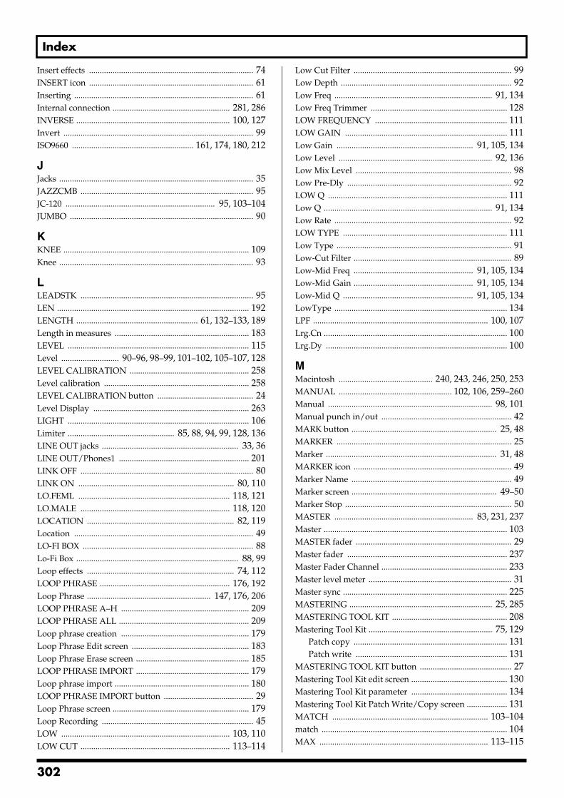
Index
Insert effects ............................................................................. 74INSERT icon ............................................................................. 61Inserting .................................................................................... 61Internal connection ....................................................... 281, 286INVERSE ........................................................................ 100, 127Invert ......................................................................................... 99ISO9660 ......................................................... 161, 174, 180, 212
JJacks ........................................................................................... 35JAZZCMB ................................................................................. 95JC-120 ...................................................................... 95, 103–104JUMBO ...................................................................................... 90
KKNEE ....................................................................................... 109Knee ........................................................................................... 93
LLEADSTK ................................................................................. 95LEN .......................................................................................... 192LENGTH ......................................................... 61, 132–133, 189Length in measures ............................................................... 183LEVEL ..................................................................................... 115Level ........................... 90–96, 98–99, 101–102, 105–107, 128LEVEL CALIBRATION ........................................................ 258Level calibration .................................................................... 258LEVEL CALIBRATION button ............................................. 24Level Display ......................................................................... 263LIGHT ..................................................................................... 106Limiter .................................................. 85, 88, 94, 99, 128, 136LINE OUT jacks ................................................................ 33, 36LINE OUT/Phones1 ............................................................. 201LINK OFF ................................................................................. 80LINK ON ......................................................................... 80, 110LO.FEML ....................................................................... 118, 121LO.MALE ...................................................................... 118, 120LOCATION ..................................................................... 82, 119Location .................................................................................... 49LO-FI BOX ................................................................................ 88Lo-Fi Box ............................................................................ 88, 99Loop effects ..................................................................... 74, 112LOOP PHRASE ............................................................. 176, 192Loop Phrase .......................................................... 147, 176, 206LOOP PHRASE A–H ............................................................ 209LOOP PHRASE ALL ............................................................. 209Loop phrase creation ............................................................ 179Loop Phrase Edit screen ....................................................... 183Loop Phrase Erase screen ..................................................... 185LOOP PHRASE IMPORT ..................................................... 179Loop phrase import ............................................................... 180LOOP PHRASE IMPORT button .......................................... 29Loop Phrase screen ................................................................ 179Loop Recording ....................................................................... 45LOW ............................................................................... 103, 110LOW CUT ...................................................................... 113–114
Low Cut Filter .......................................................................... 99Low Depth ................................................................................ 92Low Freq .......................................................................... 91, 134Low Freq Trimmer ................................................................ 128LOW FREQUENCY .............................................................. 111LOW GAIN ............................................................................ 111Low Gain ................................................................ 91, 105, 134Low Level ........................................................................ 92, 136Low Mix Level ......................................................................... 98Low Pre-Dly ............................................................................. 92LOW Q .................................................................................... 111Low Q ............................................................................... 91, 134Low Rate ................................................................................... 92LOW TYPE ............................................................................. 111Low Type .................................................................................. 91Low-Cut Filter .......................................................................... 89Low-Mid Freq ........................................................ 91, 105, 134Low-Mid Gain ........................................................ 91, 105, 134Low-Mid Q ............................................................. 91, 105, 134LowType ................................................................................. 134LPF .................................................................................. 100, 107Lrg.Cn ...................................................................................... 100Lrg.Dy ..................................................................................... 100
MMacintosh ............................................ 240, 243, 246, 250, 253MANUAL ..................................................... 102, 106, 259–260Manual ............................................................................. 98, 101Manual punch in/out ............................................................. 42MARK button .................................................................... 25, 48MARKER .................................................................................. 25Marker ................................................................................ 31, 48MARKER icon .......................................................................... 49Marker Name ........................................................................... 49Marker screen .................................................................... 49–50Marker Stop .............................................................................. 50MASTER ................................................................. 83, 231, 237Master ...................................................................................... 103MASTER fader ......................................................................... 29Master fader ........................................................................... 237Master Fader Channel ........................................................... 233Master level meter ................................................................... 31Master sync ............................................................................. 225MASTERING ................................................................... 25, 285MASTERING TOOL KIT ...................................................... 208Mastering Tool Kit .......................................................... 75, 129
Patch copy ........................................................................ 131Patch write ....................................................................... 131
MASTERING TOOL KIT button ........................................... 27Mastering Tool Kit edit screen ............................................. 130Mastering Tool Kit parameter ............................................. 134Mastering Tool Kit Patch Write/Copy screen ................... 131MATCH ......................................................................... 103–104match ....................................................................................... 104MAX ............................................................................... 113–115
302
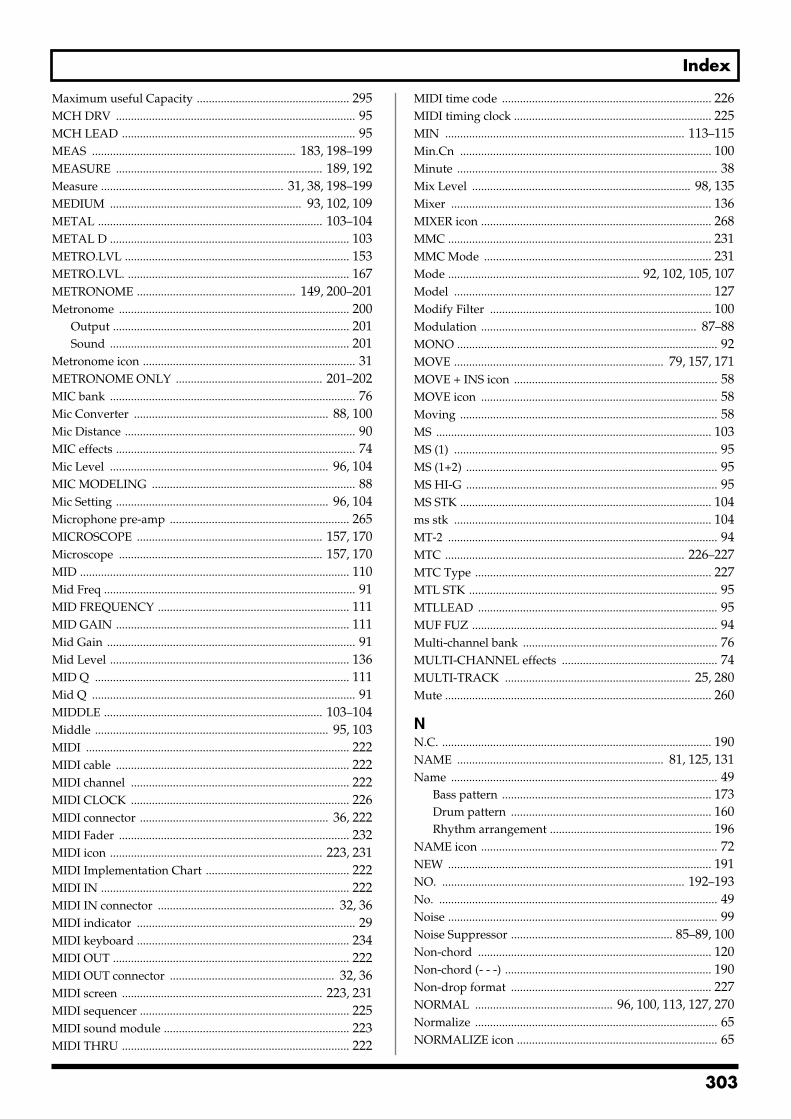
Index
Maximum useful Capacity ................................................... 295MCH DRV ................................................................................ 95MCH LEAD .............................................................................. 95MEAS .................................................................... 183, 198–199MEASURE ..................................................................... 189, 192Measure ............................................................. 31, 38, 198–199MEDIUM ................................................................ 93, 102, 109METAL ........................................................................... 103–104METAL D ................................................................................ 103METRO.LVL ........................................................................... 153METRO.LVL. .......................................................................... 167METRONOME ..................................................... 149, 200–201Metronome ............................................................................. 200
Output ............................................................................... 201Sound ................................................................................ 201
Metronome icon ....................................................................... 31METRONOME ONLY ................................................. 201–202MIC bank .................................................................................. 76Mic Converter ................................................................. 88, 100Mic Distance ............................................................................. 90MIC effects ................................................................................ 74Mic Level ......................................................................... 96, 104MIC MODELING .................................................................... 88Mic Setting ....................................................................... 96, 104Microphone pre-amp ............................................................ 265MICROSCOPE .............................................................. 157, 170Microscope .................................................................... 157, 170MID .......................................................................................... 110Mid Freq .................................................................................... 91MID FREQUENCY ................................................................ 111MID GAIN .............................................................................. 111Mid Gain ................................................................................... 91Mid Level ................................................................................ 136MID Q ..................................................................................... 111Mid Q ........................................................................................ 91MIDDLE ......................................................................... 103–104Middle .............................................................................. 95, 103MIDI ........................................................................................ 222MIDI cable .............................................................................. 222MIDI channel ......................................................................... 222MIDI CLOCK ......................................................................... 226MIDI connector ............................................................... 36, 222MIDI Fader ............................................................................. 232MIDI icon ....................................................................... 223, 231MIDI Implementation Chart ................................................ 222MIDI IN ................................................................................... 222MIDI IN connector ........................................................... 32, 36MIDI indicator ......................................................................... 29MIDI keyboard ....................................................................... 234MIDI OUT ............................................................................... 222MIDI OUT connector ....................................................... 32, 36MIDI screen ................................................................... 223, 231MIDI sequencer ...................................................................... 225MIDI sound module .............................................................. 223MIDI THRU ............................................................................ 222
MIDI time code ...................................................................... 226MIDI timing clock .................................................................. 225MIN ................................................................................ 113–115Min.Cn .................................................................................... 100Minute ....................................................................................... 38Mix Level ......................................................................... 98, 135Mixer ....................................................................................... 136MIXER icon ............................................................................. 268MMC ........................................................................................ 231MMC Mode ............................................................................ 231Mode ................................................................ 92, 102, 105, 107Model ...................................................................................... 127Modify Filter .......................................................................... 100Modulation ........................................................................ 87–88MONO ....................................................................................... 92MOVE ...................................................................... 79, 157, 171MOVE + INS icon .................................................................... 58MOVE icon ............................................................................... 58Moving ...................................................................................... 58MS ............................................................................................ 103MS (1) ........................................................................................ 95MS (1+2) .................................................................................... 95MS HI-G .................................................................................... 95MS STK .................................................................................... 104ms stk ...................................................................................... 104MT-2 .......................................................................................... 94MTC ................................................................................ 226–227MTC Type ............................................................................... 227MTL STK ................................................................................... 95MTLLEAD ................................................................................ 95MUF FUZ .................................................................................. 94Multi-channel bank ................................................................. 76MULTI-CHANNEL effects .................................................... 74MULTI-TRACK .............................................................. 25, 280Mute ......................................................................................... 260
NN.C. .......................................................................................... 190NAME ..................................................................... 81, 125, 131Name ......................................................................................... 49
Bass pattern ...................................................................... 173Drum pattern ................................................................... 160Rhythm arrangement ...................................................... 196
NAME icon ............................................................................... 72NEW ........................................................................................ 191NO. ................................................................................. 192–193No. ............................................................................................. 49Noise .......................................................................................... 99Noise Suppressor ...................................................... 85–89, 100Non-chord .............................................................................. 120Non-chord (- - -) ..................................................................... 190Non-drop format ................................................................... 227NORMAL .............................................. 96, 100, 113, 127, 270Normalize ................................................................................. 65NORMALIZE icon ................................................................... 65
303
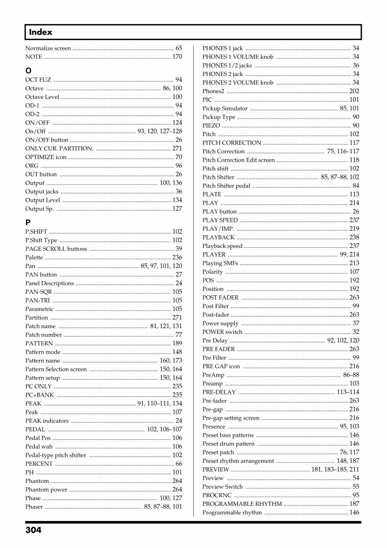
Index
Normalize screen ..................................................................... 65NOTE ....................................................................................... 170
OOCT FUZ .................................................................................. 94Octave .............................................................................. 86, 100Octave Level ........................................................................... 100OD-1 .......................................................................................... 94OD-2 .......................................................................................... 94ON/OFF ................................................................................. 124On/Off ............................................................ 93, 120, 127–128ON/OFF button ....................................................................... 26ONLY CUR. PARTITION. ................................................... 271OPTIMIZE icon ........................................................................ 70ORG ........................................................................................... 96OUT button .............................................................................. 26Output ............................................................................ 100, 136Output jacks ............................................................................. 36Output Level .......................................................................... 134Output Sp. .............................................................................. 127
PP.SHIFT ................................................................................... 102P.Shift Type ............................................................................ 102PAGE SCROLL buttons .......................................................... 39Palette ...................................................................................... 236Pan ..................................................................... 85, 97, 101, 120PAN button .............................................................................. 27Panel Descriptions ................................................................... 24PAN-SQR ................................................................................ 105PAN-TRI ................................................................................. 105Parametric ............................................................................... 105Partition .................................................................................. 271Patch name ............................................................. 81, 121, 131Patch number ........................................................................... 77PATTERN ............................................................................... 189Pattern mode .......................................................................... 148Pattern name ................................................................. 160, 173Pattern Selection screen ............................................... 150, 164Pattern setup ................................................................. 150, 164PC ONLY ................................................................................ 235PC+BANK .............................................................................. 235PEAK ............................................................... 91, 110–111, 134Peak ......................................................................................... 107PEAK indicators ...................................................................... 24PEDAL .................................................................. 102, 106–107Pedal Pos ................................................................................. 106Pedal wah ............................................................................... 106Pedal-type pitch shifter ........................................................ 102PERCENT ................................................................................. 66PH ............................................................................................ 101Phantom .................................................................................. 264Phantom power ..................................................................... 264Phase ............................................................................... 100, 127Phaser .................................................................. 85, 87–88, 101
PHONES 1 jack ........................................................................ 34PHONES 1 VOLUME knob ................................................... 34PHONES 1/2 jacks .................................................................. 36PHONES 2 jack ........................................................................ 34PHONES 2 VOLUME knob ................................................... 34Phones2 ................................................................................... 202PIC ........................................................................................... 101Pickup Simulator ............................................................ 85, 101Pickup Type .............................................................................. 90PIEZO ........................................................................................ 90Pitch ......................................................................................... 102PITCH CORRECTION .......................................................... 117Pitch Correction ..................................................... 75, 116–117Pitch Correction Edit screen ................................................. 118Pitch shift ................................................................................ 102Pitch Shifter ........................................................ 85, 87–88, 102Pitch Shifter pedal ................................................................... 84PLATE ..................................................................................... 113PLAY ....................................................................................... 214PLAY button ............................................................................. 26PLAY SPEED .......................................................................... 237PLAY/IMP. ............................................................................ 219PLAYBACK ............................................................................ 238Playback speed ....................................................................... 237PLAYER ........................................................................... 99, 214Playing SMFs .......................................................................... 213Polarity .................................................................................... 107POS .......................................................................................... 192Position ................................................................................... 192POST FADER ......................................................................... 263Post Filter .................................................................................. 99Post-fader ................................................................................ 263Power supply ........................................................................... 37POWER switch ......................................................................... 32Pre Delay ................................................................. 92, 102, 120PRE FADER ............................................................................ 263Pre Filter .................................................................................... 99PRE GAP icon ........................................................................ 216PreAmp .............................................................................. 86–88Preamp .................................................................................... 103PRE-DELAY .................................................................. 113–114Pre-fader ................................................................................. 263Pre-gap .................................................................................... 216Pre-gap setting screen ........................................................... 216Presence ........................................................................... 95, 103Preset bass patterns ............................................................... 146Preset drum pattern .............................................................. 146Preset patch ..................................................................... 76, 117Preset rhythm arrangement ........................................ 148, 187PREVIEW ...................................................... 181, 183–185, 211Preview ..................................................................................... 54Preview Switch ........................................................................ 55PROCRNC ................................................................................ 95PROGRAMMABLE RHYTHM ............................................ 187Programmable rhythm ......................................................... 146
304
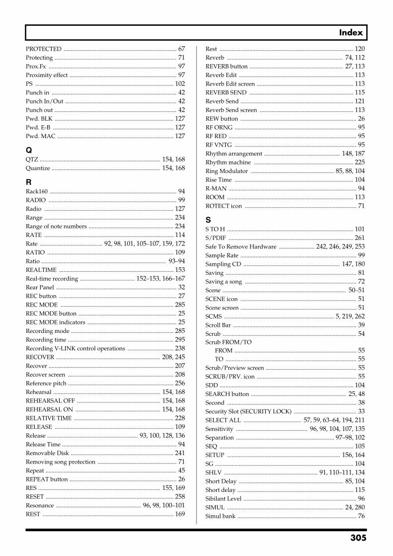
Index
PROTECTED ............................................................................ 67Protecting .................................................................................. 71Prox.Fx ...................................................................................... 97Proximity effect ........................................................................ 97PS ............................................................................................. 102Punch in .................................................................................... 42Punch In/Out ........................................................................... 42Punch out .................................................................................. 42Pwd. BLK ................................................................................ 127Pwd. E-B ................................................................................. 127Pwd. MAC .............................................................................. 127
QQTZ ................................................................................. 154, 168Quantize ......................................................................... 154, 168
RRack160 ..................................................................................... 94RADIO ...................................................................................... 99Radio ....................................................................................... 127Range ....................................................................................... 234Range of note numbers ......................................................... 234RATE ....................................................................................... 114Rate .......................................... 92, 98, 101, 105–107, 159, 172RATIO ..................................................................................... 109Ratio .................................................................................... 93–94REALTIME ............................................................................. 153Real-time recording ..................................... 152–153, 166–167Rear Panel ................................................................................. 32REC button ............................................................................... 27REC MODE ............................................................................ 285REC MODE button .................................................................. 25REC MODE indicators ............................................................ 25Recording mode ..................................................................... 285Recording time ....................................................................... 295Recording V-LINK control operations ............................... 238RECOVER ...................................................................... 208, 245Recover .................................................................................... 207Recover screen ....................................................................... 208Reference pitch ....................................................................... 256Rehearsal ........................................................................ 154, 168REHEARSAL OFF ........................................................ 154, 168REHEARSAL ON ......................................................... 154, 168RELATIVE TIME ................................................................... 228RELEASE ................................................................................ 109Release ............................................................. 93, 100, 128, 136Release Time ............................................................................. 94Removable Disk ..................................................................... 241Removing song protection ..................................................... 71Repeat ........................................................................................ 45REPEAT button ........................................................................ 26RES .................................................................................. 155, 169RESET ...................................................................................... 258Resonance ......................................................... 96, 98, 100–101REST ........................................................................................ 169
Rest .......................................................................................... 120Reverb .............................................................................. 74, 112REVERB button ............................................................... 27, 113Reverb Edit ............................................................................. 113Reverb Edit screen ................................................................. 113REVERB SEND ...................................................................... 115Reverb Send ............................................................................ 121Reverb Send screen ............................................................... 113REW button .............................................................................. 26RF ORNG .................................................................................. 95RF RED ...................................................................................... 95RF VNTG .................................................................................. 95Rhythm arrangement ................................................... 148, 187Rhythm machine ................................................................... 225Ring Modulator ........................................................ 85, 88, 104Rise Time ................................................................................ 104R-MAN ...................................................................................... 94ROOM ..................................................................................... 113ROTECT icon ........................................................................... 71
SS TO H ..................................................................................... 101S/PDIF .................................................................................... 261Safe To Remove Hardware ........................ 242, 246, 249, 253Sample Rate .............................................................................. 99Sampling CD ................................................................. 147, 180Saving ........................................................................................ 81Saving a song ........................................................................... 72Scene ................................................................................... 50–51SCENE icon .............................................................................. 51Scene screen .............................................................................. 51SCMS .......................................................................... 5, 219, 262Scroll Bar ................................................................................... 39Scrub .......................................................................................... 54Scrub FROM/TO
FROM .................................................................................. 55TO ........................................................................................ 55
Scrub/Preview screen ............................................................. 55SCRUB/PRV. icon ................................................................... 55SDD .......................................................................................... 104SEARCH button ................................................................ 25, 48Second ....................................................................................... 38Security Slot (SECURITY LOCK) .......................................... 33SELECT ALL ....................................... 57, 59, 63–64, 194, 211Sensitivity ................................................ 96, 98, 104, 107, 135Separation .................................................................. 97–98, 102SEQ .......................................................................................... 105SETUP ............................................................................ 156, 164SG ............................................................................................. 104SHLV ............................................................... 91, 110–111, 134Short Delay ...................................................................... 85, 104Short delay .............................................................................. 115Sibilant Level ............................................................................ 96SIMUL .............................................................................. 24, 280Simul bank ................................................................................ 76
305
Index
SIMUL effects ........................................................................... 74SINGLE ..................................................................................... 97Single to Hum ........................................................................ 101Single-coil ............................................................................... 101Size of each partition ............................................................. 269SLDN ................................................................................ 95, 103SLOW ...................................................................................... 102Slow Gear ......................................................................... 85, 104SMALL .................................................................................... 104SmallTV ................................................................................... 127SMF ................................................................ 161–162, 174, 213SMF import .................................................................... 161, 174SMF Import screen ....................................................... 162, 175SMF player ............................................................................. 213Sml.Cn ..................................................................................... 100Sml.Dy ..................................................................................... 100SmlCUBE ................................................................................ 127Smooth .................................................................................... 118SOFT ................................................................................. 93, 109Soft Clip .................................................................................. 136Song backup ........................................................................... 204Song Backup screen ............................................................... 204Song bass pattern ................................................................... 146Song Copy ................................................................................ 68Song drum pattern ................................................................ 146Song Erase ................................................................................ 69SONG icon ................................................................................ 67Song Information ..................................................................... 67Song Information screen ......................................................... 67Song loop phrase .......................................................... 147, 177Song Menu screen ................................................................... 67Song Name ........................................................................ 31, 72Song name ................................................................................ 67Song Name screen ................................................................... 72Song number ............................................................................ 67Song Optimize ......................................................................... 70Song patch ....................................................................... 76, 117Song Protect .............................................................................. 71Song protection ........................................................................ 67Song recover ........................................................................... 207Song rhythm arrangement .......................................... 148, 187Song Save .................................................................................. 72SP Modeling ........................................................................... 127SPEAKER MODELING ........................................................ 208Speaker Modeling ........................................................... 75, 123
Patch copy ........................................................................ 126Patch write ....................................................................... 125
SPEAKER MODELING button ............................................. 28Speaker Modeling edit screen ............................................. 124Speaker Modeling parameter .............................................. 127Speaker Modeling patch ....................................................... 124Speaker Modeling patch screen ........................................... 124Speaker Modeling Patch Write/Copy screen ................... 126Speaker Simulator .................................................... 86–88, 104Speaker SW ............................................................................... 95
Speaker Type ................................................................... 96, 104Split Freq H ............................................................................. 135Split Freq L ............................................................................. 135Spr Flat .................................................................................... 127START ............................................................................ 132–133START (Start point) ............. 57, 59, 61, 63–64, 180, 194, 211STD ............................................................................................ 90Steady green ............................................................................. 27Steady red ................................................................................. 27STEP ................................................................................ 155, 169Step .......................................................................................... 101STEP BACK ............................................................................ 169Step Rate ................................................................................. 101Step recording .............................................. 152, 155, 166, 169STEREO ..................................................................................... 92Stereo bank ............................................................................... 76STEREO effects ........................................................................ 74Stereo Link .............................................................. 80, 110–111STEREO MULTI ....................................................................... 88STEREO TRACKS ........................................................... 25, 280STKCRNC ................................................................................. 95STOP button ............................................................................. 26Sub Equalizer .................................................................. 85, 105Sub Mixer ................................................................................ 266Sub-frame .................................................................................. 38SUB-MIX ................................................................................. 261Supported combinations of effects ........................................ 75SURFACE SCAN ................................................................... 270Sustain ................................................................................ 93–94Swing .............................................................................. 159, 172Swing Pos. ..................................................................... 159, 172Sync Generator ....................................................................... 226SYNC icon ...................................................................... 225–226Sync Offset .............................................................................. 230Sync Source ............................................................................. 229SYNC TRACK ........................................................................ 229Sync track ................................................................................ 228SYNC TRACK icon ................................................................ 229Synchronization setting screen ............................................ 226Synchronize ................................................................... 225, 276
TT BAR ...................................................................................... 237T bar ......................................................................................... 237TAP ........................................................................ 151, 178, 188TAP button ............................................................................... 28Tap tempo ............................................................. 151, 178, 188Tap Time ................................................................................... 97TEMPO .......................................................... 151, 178, 188, 198Tempo ............................................................................ 156, 198
Bass pattern ...................................................................... 165Drum pattern ................................................................... 151Loop phrase ..................................................................... 178Rhythm arrangement ...................................................... 187
TEMPO MAP ......................................................................... 198
306
Index
Tempo map ............................................................................ 198Tempo Map screen ................................................................ 198TEMPO MATCH ................................................................... 192Three-band compressor ........................................................ 129Three-band equalizers ................................................... 74, 108THRESHOLD ......................................................................... 109Threshold ........................................... 93–94, 99–100, 128, 136THRU ........................................................................................ 99TIME ............................................................................... 113–114Time .................................................................................... 31, 97Time Display Format ............................................................ 228Time Offset ............................................................................. 228TIME/VALUE dial ........................................................... 29, 40TIMES (copy time) ................................................................... 57TMP ........................................................................................... 78TO ............................................ 81–82, 121–122, 125–126, 131TO (To point) ..................................................................... 57, 59TO TRACK icon ..................................................................... 194TONE ....................................................................................... 113Tone ............................................................... 93–94, 96, 99, 101TOP .......................................................................................... 192Top ............................................................................................. 90Top screen ................................................................................. 38Top-Hi ....................................................................................... 90Top-Mid .................................................................................... 90TOUCH ................................................................................... 107Touch wah .............................................................................. 106TRACK 1 ................................................................................... 83Track 1 Channel ..................................................................... 233TRACK 1/2 .............................................................................. 83Track 15&16 Channel ............................................................ 233TRACK 1-8 ................................................................................ 83TRACK 9-16 ..................................................................... 83, 110Track buttons 1–8, 9/10–15/16 .............................................. 27Track Copy ............................................................................... 56Track Copy screen ................................................................... 57Track Cut .................................................................................. 62Track Cut screen ...................................................................... 62Track Edit ................................................................................. 56Track Erase ............................................................................... 63Track Erase screen ................................................................... 63Track Exchange ........................................................................ 60Track Exchange screen ............................................................ 60Track faders .............................................................................. 27TRACK icon ............................................................................. 56Track Insert ............................................................................... 61Track Insert screen .................................................................. 61Track Level ............................................................................... 51
FADER ................................................................................ 51SCENE ................................................................................ 51
Track Move ............................................................................... 58Track Move screen .................................................................. 58TRACK MUTE button ............................................................ 28Track Name .............................................................................. 47Track screen .............................................................................. 56
Track status .............................................................................. 27Track type ..................................................... 149, 163, 176, 200TRACK TYPE indicators ........................................................ 29TRACK TYPE SELECT ............................... 149, 163, 176, 200TRACK TYPE SELECT button ............................................... 29Track Type Select screen ............................. 149, 163, 176, 200Track types ............................................................................... 29Treble ................................................................................ 95, 103Tremolo ............................................................................ 85, 105Tremolo/Pan ...................................................... 85, 87–88, 105TRM/PAN .............................................................................. 105TRM-SQR ................................................................................ 105TRM-TRI ................................................................................. 105Troubleshooting ..................................................................... 274TSCREAM ................................................................................. 94Tuner ....................................................................................... 256TUNER ON/OFF .................................................................. 256TUNER ON/OFF button ........................................................ 25Tuner screen ........................................................................... 256Tuning .............................................................................. 99, 256TURBO OD ............................................................................... 94Turntable ................................................................................... 99TWEED ..................................................................................... 95Twice as fast ......................................................... 205–207, 212TWIN ....................................................................................... 104twin .......................................................................................... 104TYPE ............................................................................... 113–115Type .................................................... 94–95, 97, 101, 106, 118
UUM-1 ........................................................................................ 236UM-1S ...................................................................................... 236UNDO/REDO button ............................................................. 29Uni-V ................................................................................ 85, 105Universal serial bus ............................................................... 240Unneeded data ......................................................................... 70UP ............................................................................................ 107USB .......................................................................... 37, 240, 276
Host ..................................................................................... 37Hub ...................................................................................... 37
USB cable .................................................................................. 37USB connector ................................................................... 32, 37USB icon .................................................................................. 242USB screen .............................................................................. 242User backup ............................................................................ 205User Backup screen ............................................................... 205User bass pattern ................................................................... 146User drum pattern ................................................................. 146User loop phrase ........................................................... 147, 177User patch ........................................................................ 76, 117User recover ........................................................................... 208User rhythm arrangement ........................................... 148, 187UTILITY button ....................................................................... 29UV ............................................................................................ 105
307
Index
VVALUE 1/PAN, VALUE 2, VALUE 3, and VALUE 4 knobs ........... 40VALUE knobs ................................................................... 29, 78VB ............................................................................................. 106VFX1 ........................................................................................ 237VFX2 ........................................................................................ 237VFX3 ........................................................................................ 237VFX4 ........................................................................................ 237Vibrato .............................................................................. 85, 106Vibrato pedal ............................................................................ 84Video device ........................................................................... 236Visual effects 1 ....................................................................... 237Visual effects 2 ....................................................................... 237Visual effects 3 ....................................................................... 237Visual effects 4 ....................................................................... 237V-LINK .................................................................................... 236V-LINK button ......................................................................... 28V-LINK REC ........................................................................... 238V-LINK REC button ................................................................ 28Vnt.Cn ..................................................................................... 100VO CLEAN ............................................................................... 95VO DRV .................................................................. 95, 103–104vo drv ...................................................................................... 104VO LEAD .................................................................................. 95VO WAH ................................................................................ 106VO+AC.SIM ............................................................................. 89VO+ACOUSTIC ...................................................................... 89VO+GT.AMP ............................................................................ 88Voc.Dy ..................................................................................... 100VOCAL ............................................................................ 24, 280VOCAL MULTI ....................................................................... 87VOCAL TOOL BOX .............................................................. 208Vocal Tool Box ................................................................ 75, 116
Patch copy ........................................................................ 122Patch write ....................................................................... 121
VOCAL TOOL BOX button ................................. 27, 117, 119Vocal Tool Box Write/Copy screen ........................... 121–122Voice ........................................................................................ 102Voice character ....................................................................... 106VOICE TRANSFORMER ........................................................ 87Voice Transformer .......................................................... 87, 106VOICE1 ................................................................................... 120VOL ......................................................................................... 192Volume .................................................................................... 103Volume pedal ........................................................................... 84Volume-swell effect ............................................................... 104Vowel ........................................................................................ 98Vowel1 ...................................................................................... 98Vowel2 ...................................................................................... 98VtgRack ..................................................................................... 94V-Track ...................................................................................... 46V-TRACK button ..................................................................... 28
WWAH ....................................................................................... 106Wah ............................................................................. 85–88, 106Wah pedal ................................................................................. 84Wah Type ................................................................................ 107WAV .............................................................. 180, 212, 248, 250WAV file ................................................................................. 210WAV/AIFF export ....................................................... 211, 248WAV/AIFF import ...................................................... 210, 252WAV/AIFF screen ................................................................ 210Wave Shape ................................................................... 101, 105Waveform Data Export screen ............................................. 211Wh.CONE ............................................................................... 127WhTISUE ................................................................................ 127Windows .............................................. 240, 242, 245, 248, 252Wow Flutter ............................................................................. 99WRITE ..................................................................................... 216Write Speed .......................................................... 205–207, 212WRITE/COPY ........................ 81–82, 121–122, 125–126, 131WRITE/COPY/DEL .................................................... 153, 196Write/Copy/Delete screen for drum patterns ................. 153
XXG ................................................................................... 162, 175Xover Freq ................................................................................ 92
ZZERO button ............................................................................ 26
308

309
MEMO

310
MEMO
This product complies with the requirements of European Directive 89/336/EEC.
For EU Countries
For Canada
This Class B digital apparatus meets all requirements of the Canadian Interference-Causing Equipment Regulations.
Cet appareil numérique de la classe B respecte toutes les exigences du Règlement sur le matériel brouilleur du Canada.
NOTICE
AVIS
For the USA
FEDERAL COMMUNICATIONS COMMISSIONRADIO FREQUENCY INTERFERENCE STATEMENT
This equipment has been tested and found to comply with the limits for a Class B digital device, pursuant to Part 15 of the FCC Rules. These limits are designed to provide reasonable protection against harmful interference in a residential installation. This equipment generates, uses, and can radiate radio frequency energy and, if not installed and used in accordance with the instructions, may cause harmful interference to radio communications. However, there is no guarantee that interference will not occur in a particular installation. If this equipment does cause harmful interference to radio or television reception, which can be determined by turning the equipment off and on, the user is encouraged to try to correct the interference by one or more of the following measures:
– Reorient or relocate the receiving antenna.– Increase the separation between the equipment and receiver.– Connect the equipment into an outlet on a circuit different from that to which the receiver is connected.– Consult the dealer or an experienced radio/TV technician for help.
This device complies with Part 15 of the FCC Rules. Operation is subject to the following two conditions: (1) This device may not cause harmful interference, and (2) This device must accept any interference received, including interference that may cause undesired operation.
Unauthorized changes or modification to this system can void the users authority to operate this equipment.This equipment requires shielded interface cables in order to meet FCC class B Limit.
IMPORTANT: THE WIRES IN THIS MAINS LEAD ARE COLOURED IN ACCORDANCE WITH THE FOLLOWING CODE.
BLUE: BROWN:
As the colours of the wires in the mains lead of this apparatus may not correspond with the coloured markings identifying the terminals in your plug, proceed as follows:The wire which is coloured BLUE must be connected to the terminal which is marked with the letter N or coloured BLACK.The wire which is coloured BROWN must be connected to the terminal which is marked with the letter L or coloured RED.Under no circumstances must either of the above wires be connected to the earth terminal of a three pin plug.
NEUTRALLIVE
For the U.K.
2
USING THE UNIT SAFELY
001
• Before using this unit, make sure to read the instructions below, and the Owner’s Manual.
...........................................................................................................
002c
• Do not open (or modify in any way) the unit or its AC adaptor.
...........................................................................................................
003
• Do not attempt to repair the unit, or replace parts within it (except when this manual provides specific instructions directing you to do so). Refer all servicing to your retailer, the nearest Roland Service Center, or an authorized Roland distributor, as listed on the “Information” page.
...........................................................................................................
004
• Never use or store the unit in places that are:
• Subject to temperature extremes (e.g., direct sunlight in an enclosed vehicle, near a heating duct, on top of heat-generating equipment); or are
• Damp (e.g., baths, washrooms, on wet floors); or are
• Humid; or are
• Exposed to rain; or are
• Dusty; or are
• Subject to high levels of vibration............................................................................................................
007
• Make sure you always have the unit placed so it is level and sure to remain stable. Never place it on stands that could wobble, or on inclined surfaces.
...........................................................................................................
008c
• Be sure to use only the AC adaptor supplied with the unit. Also, make sure the line voltage at the installation matches the input voltage specified on the AC adaptor’s body. Other AC adaptors may use a different polarity, or be designed for a different voltage, so their use could result in damage, malfunction, or electric shock.
..........................................................................................................
008e
• Use only the attached power-supply cord. Also, the supplied power cord must not be used with any other device.
..........................................................................................................
009
• Do not excessively twist or bend the power cord, nor place heavy objects on it. Doing so can damage the cord, producing severed elements and short circuits. Damaged cords are fire and shock hazards!
..........................................................................................................
010
• This unit, either alone or in combination with an amplifier and headphones or speakers, may be capable of producing sound levels that could cause permanent hearing loss. Do not operate for a long period of time at a high volume level, or at a level that is uncomfortable. If you experience any hearing loss or ringing in the ears, you should immediately stop using the unit, and consult an audiologist.
..........................................................................................................
011
• Do not allow any objects (e.g., flammable material, coins, pins); or liquids of any kind (water, soft drinks, etc.) to penetrate the unit.
..........................................................................................................
Used for instructions intended to alert the user to the risk of injury or material damage should the unit be used improperly.
* Material damage refers to damage or other adverse effects caused with respect to the home and all its furnishings, as well to domestic animals or pets.
Used for instructions intended to alert the user to the risk of death or severe injury should the unit be used improperly.
The symbol alerts the user to things that must be carried out. The specific thing that must be done is indicated by the design contained within the circle. In the case of the symbol at left, it means that the power-cord plug must be unplugged from the outlet.
The symbol alerts the user to important instructions or warnings.The specific meaning of the symbol is determined by the design contained within the triangle. In the case of the symbol at left, it is used for general cautions, warnings, or alerts to danger.
The symbol alerts the user to items that must never be carried out (are forbidden). The specific thing that must not be done is indicated by the design contained within the circle. In the case of the symbol at left, it means that the unit must never be disassembled.

Owner’s Manual
03343912 ’06-03-7N
Thank you, and congratulations on your choice of the BOSS BR-1600CD Digital Recording Studio.
Before using this unit, carefully read the sections entitled: “USING THE UNIT SAFELY” and “IMPORTANT NOTES” (Owner’s manual p. 2–3; p. 4–5). These sections provide important information concerning the proper operation of the unit. Additionally, in order to feel assured that you have gained a good grasp of every feature provided by your new unit, Basic Operation and Owner’s manual should be read in its entirety.
The manuals should be saved and kept on hand as a convenient reference.
How to use this manual
The BR-1600CD Owner’s manual consists of two volumes “
Basic Operation
” and “
Owner’s Manual
.”
“
Basic Operation
” explains the sequence of turning on this unit, recording, playback, mixing down and making an original Audio CD. To use the BR-1600CD, please read this book first.
“
Owner’s Manual
” covers the functions which are not mentioned in “Basic Operation.” Please read it for finer settings and more sophisticated use of the BR-1600CD.
Printing conventions in this manual
• Text or numerals enclosed in square brackets [ ] indicate buttons.
[PLAY]
PLAY button
[CURSOR]
CURSOR button
• Reference such as (p. **) indicate pages in this manual to which you can refer.
Copyright © 2003 BOSS CORPORATION
All rights reserved. No part of this publication may be reproduced in any form without the written permission of BOSS CORPORATION.
Section 2
Usin
gEffects
Section 3
Using
Rhythm
Section 4
Using the
CD-R/RW
Drive
Section 5
Usin
gM
IDI
Section 6
Usin
gU
SB
Section 7
Oth
er Conven
ient
Functio
ns
Appen
dices
Section 1
Adva
nced
Use