booth display & demonstration @ #3003 · wan lan ……… sender ... - wan phy 10 gbps network...
TRANSCRIPT
SC08SC08
Booth Display & Demonstration @ #3003MaSTER-1: 5-port 10GbE Testbed
Performance Optimization of TCP/IPGRAPE-DR
Katsuyuki Hasebe
The University of Tokyo&
National Institute of Information and Communications Technology
2
Booth Display & Demonstration
• MaSTER-1– 5-port 10GbE Testbed
• Stream Harmonizer– Optimizing parallel TCP stream/performance
• Performance optimization of TCP/IP• High speed TCP communication experiments• CosmoGrid• GRAPE-DR processor chip/system

3
MaSTER-15-port 10GbE Testbed
MaSTER-1 Overview
•10GbE (LAN PHY) experimental testbed•5 XFP ports connected to FPGAs through MACs•All FPGAs are connected all-to-all at the speed of 10 Gbps•FPGAs can be communicated with a control PC thorough a USB port
MaSTER-1 Advantages
•Packets input from a port can be processed at the speed of 10 Gbps•Packets can be output from any ports•Each port has powerful configurable FPGA•Each port has large memories to store packets
MaSTER-1 (12 Layers PCB) MaSTER-1 Applications
・Programmable 10GbE switch•Currently running
•Packet Filters•Packet Logger•Pseudo Long Fat-pipe Networks
•Maximum 400 ms delay
MaSTER-1 improves theperformance of Parallel TCPStreams
•Multiple ports allow MaSTER-1 tohandle multiple connectionswithout switches•MaSTER-1 can observe directlythe packets transmitted by endhosts•MaSTER-1 will clarify theproblems with the method fordropping and merging packets in10GbE switches• MaSTER-1 is a good tool forverifying the performance ofparallel TCP streams on Long Fat-pipe Networks (LFNs)

4
MaSTER-15-port 10GbE Testbed
MaSTER-1 Specification
Ports 5 XFPs (10GBASE-SR/LR)Processors 5 FPGAs (Xilinx XC5VFX70T-1FF1136) – 1 for each portInterconnection All-to-all 10 Gbps – Xilinx Rocket IOMemory DDR2 SDRAM 2.56 GiB – 512 MiB for each processorI/O USB 2.0Dimension 430 mm x 430 mm x 50mm (WDH)
MaSTER-1 FPGA Interconnections
GTXIF
SPIIF
GTXIF
SPIIF
DDR2512MB
FIFO
GTXIF
SPIIF
DDR2512MB
DDR2512MB
MaSTER-1 Block Diagram
FPGA
FPGA
FPGA FPGA
FPGA
MACSerdes
XFP
10GBASE-SR/LR
CPLD
FPGA Controller
USB
MACSerdes
MACSerdes
MACSerdes
MACSerdes10GBASE-SR/LR
10GBASE-SR/LR
10GBASE-SR/LR
10GBASE-SR/LR
MaSTER-1 in a Rack
5
Stream Harmonizeroptimizing parallel TCP stream/performance
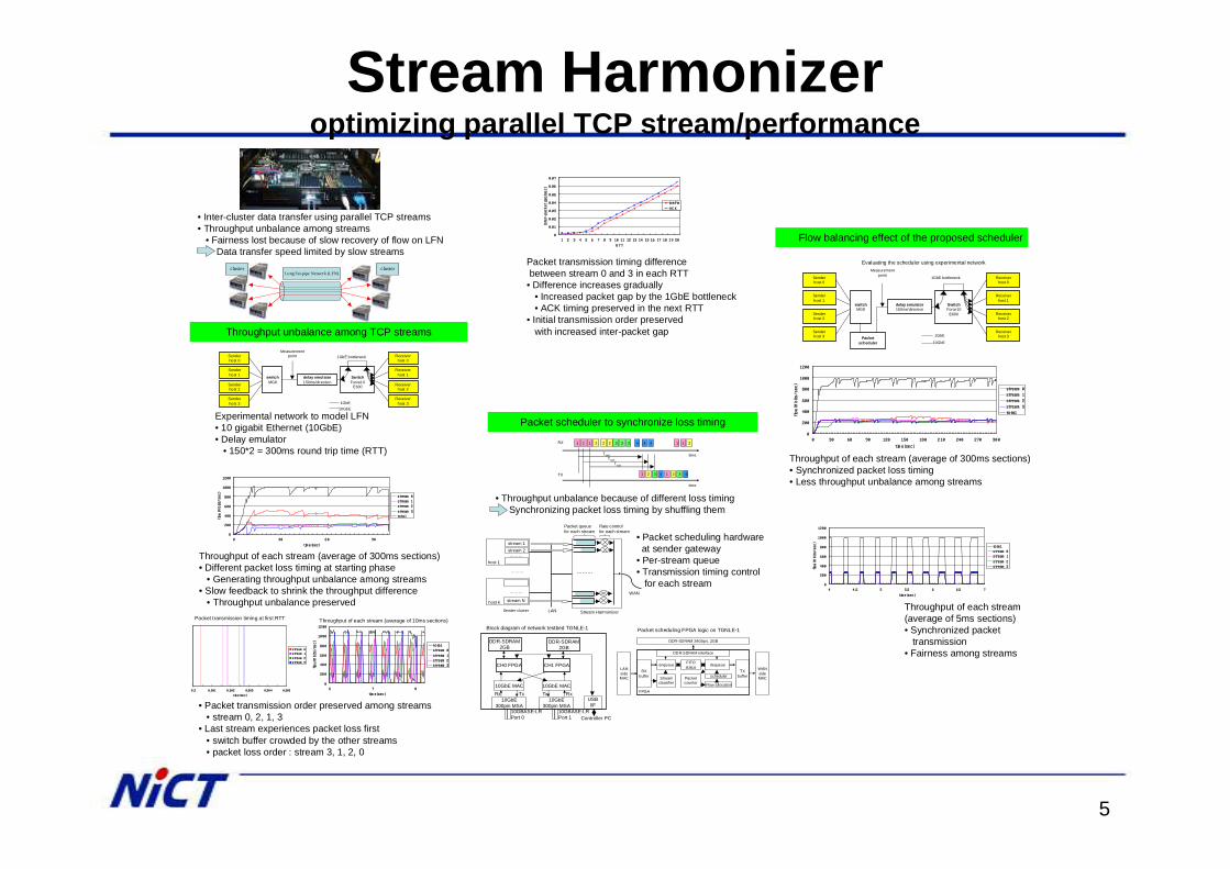
• Inter-cluster data transfer using parallel TCP streams• Throughput unbalance among streams
• Fairness lost because of slow recovery of flow on LFNData transfer speed limited by slow streams
cluster clusterLong Fat-pipe Network (LFN)
0
200
400
600
800
1000
1200
0 30 60 90
time (sec)
flow(Mbits/sec)
stream 0
stream 1
stream 2
stream 3
total
Throughput unbalance among TCP streams
Experimental network to model LFN• 10 gigabit Ethernet (10GbE)• Delay emulator
• 150*2 = 300ms round trip time (RTT)
Throughput of each stream (average of 300ms sections)• Different packet loss timing at starting phase
• Generating throughput unbalance among streams• Slow feedback to shrink the throughput difference
• Throughput unbalance preserved
Senderhost 0
switchMG8
delay emulator150ms/direction
SwitchForce10
E600
Senderhost 1
Senderhost 2
Senderhost 3
Receiverhost 0
Receiverhost 1
Receiverhost 2
Receiverhost 3
1GbE bottleneck
10GbE1GbE
Measurementpoint
0
200
400
600
800
1000
1200
6 7 8
time(sec)
flow(Mbits/sec)
total
stream 0
stream 1
stream 2
stream 3
0 .3 0.301 0 .302 0.303 0.30 4 0.305
time (se c)
stream 0
stream 1
stream 2
stream 3
• Packet transmission order preserved among streams• stream 0, 2, 1, 3
• Last stream experiences packet loss first• switch buffer crowded by the other streams• packet loss order : stream 3, 1, 2, 0
Packet transmission timing at first RTT Throughput of each stream (average of 10ms sections)
0
0.01
0.02
0.03
0.04
0.05
0.06
0.07
1 2 3 4 5 6 7 8 9 10 11 12 13 14 15 16 17 18 19 20
RTT
inter-packet gap(sec)
DATA
ACK
Packet transmission timing differencebetween stream 0 and 3 in each RTT
• Difference increases gradually• Increased packet gap by the 1GbE bottleneck• ACK timing preserved in the next RTT
• Initial transmission order preservedwith increased inter-packet gap
stream 1
host 1
stream 2
host k
………
………
stream N
………
WAN
LAN
………
Stream HarmonizerSender cluster
Rate controlfor each stream
Packet queuefor each stream
2 3 41
time
time
1 1 2 3 3 4 1 1 2
1 2 3 4
2 4
1 2 3 4
Twait
RX
TX
TwaitTwait
10GBASE-LRPort 0
USBI/F
Controller PC
CH0 FPGA
10GbE MAC
10GbE300pin MSA
DDR-SDRAM2GB
Rx Tx
CH1 FPGA
10GbE MAC
10GbE300pin MSA
DDR-SDRAM2GB
RxTx
10GBASE-LRPort 1
LANsideMAC
FPGA
RXbuffer
DDR-SDRAM 34Gbps, 2GB
DDR-SDRAM interface
Streamclassifier
enqueue FIFOstatus WAN
sideMAC
dequeue
Packetcounter Flow allocation
schedulerTX
buffer
Packet scheduler to synchronize loss timing
• Throughput unbalance because of different loss timingSynchronizing packet loss timing by shuffling them
• Packet scheduling hardwareat sender gateway
• Per-stream queue• Transmission timing control
for each stream
Block diagram of network testbed TGNLE-1 Packet scheduling FPGA logic on TGNLE-1
Senderhost 0
switchMG8
delay emulator150ms/direction
SwitchForce10
E600
Senderhost 1
Senderhost 2
Senderhost 3
Receiverhost 0
Receiverhost 1
Receiverhost 2
Receiverhost 3
1GbE bottleneck
10GbE
1GbE
Measurementpoint
Packetscheduler
0
200
400
600
800
1000
1200
0 30 60 90 120 150 180 210 240 270 300
time(sec)
flow(Mbits/sec)
stream 0
stream 1
stream 2
stream 3
total
Flow balancing effect of the proposed scheduler
Evaluating the scheduler using experimental network
Throughput of each stream (average of 300ms sections)• Synchronized packet loss timing• Less throughput unbalance among streams
0
200
400
600
800
1000
1200
4 4.5 5 5.5 6 6.5 7
time (sec)
flow(Mbits/sec)
total
stream 0
stream 1
stream 2
stream 3
Throughput of each stream(average of 5ms sections)• Synchronized packet
transmission• Fairness among streams
6
Rx Queue Tx Queue
Rx Queue
SwitchSwitchBottleneck
PackedBursty ACKs
Tx Queue Rx Queue Tx Queue
Rx Queue Tx Queue
Overflow
NetworkNetworknetwork
Possible Causes of Performane Decrease
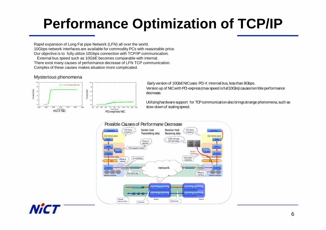
Performance Optimization of TCP/IPRapid expansion of Long Fat pipe Network (LFN) all over the world.10Gbps network interfaces are available for commodity PCs with reasonable price. Our objective is to fully utilize 10Gbps connection with TCP/IP communication.
External bus speed such as 10GbE becomes comparable with internal.There exist many causes of performance decrease of LFN TCP communication. Complex of these causes makes situation more complicated.
PCI-X NIC PCI-express NIC
Early version of 10GbE NIC uses PCI-X internal bus, less than 8Gbps.Version up of NIC with PCI-express (max speed is full10Gbs) causes terrible performance decrease.
Utilizing hardware support for TCP communication also brings strange phenomena, such as slow-down of scaling speed.
Mysterious phenomena
7
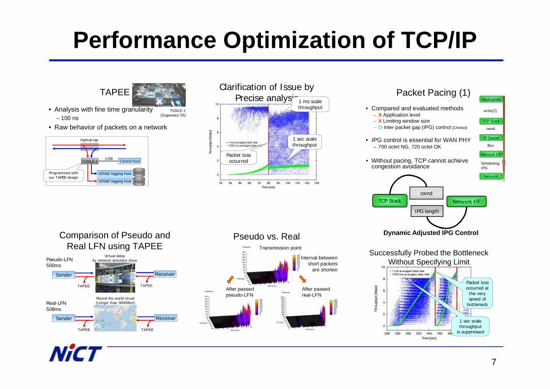
Performance Optimization of TCP/IP
TAPEE
• Analysis with fine time granularity– 100 ns
• Raw behavior of packets on a network
Optical tap
TGNLE-1
10GbE logging host
10GbE logging host
Control hostUSB
HDD
TGNLE-1[Sugawara ‘05]
Programmed withour TAPEE design
HDD
Comparison of Pseudo and Real LFN using TAPEE
TAPEE
TAPEE
Pseudo-LFN500ms
Real-LFN508ms
Virtual delayby network simulator Anue
Round the world circuit(Longer than 30000km)
TAPEE
TAPEE
ReceiverSender
ReceiverSender
Clarification of Issue byPrecise analysis1 ms scale
throughput
1 sec scalethroughput
Packet lossoccurred
Pseudo vs. RealTransmission point
Interval betweenshort packets
are shorten
After passedpseudo-LFN
After passedreal-LFN
Packet Pacing (1)• Compared and evaluated methods
– X Application level– X Limiting window size– O Inter packet gap (IPG) control [Chelsio]
• IPG control is essential for WAN PHY– 700 octet NG, 720 octet OK
• Without pacing, TCP cannot achievecongestion avoidance
cwnd
Bus
write(2)
Scheduling,IPG
Application
TCP Stack
IF Queue
Network I/F
Network
cwnd
IPG length
TCP Stack Network I/F
Dynamic Adjusted IPG Control
Successfully Probed the BottleneckWithout Specifying Limit
1 sec scalethroughput
is suppressed
Packet lossoccurred at
the very speed of
bottleneck
8
Internet2 Land Speed Record
• 99% of physical bandwidth for 5 hours on 522ms RTT network

9
Thank you
10
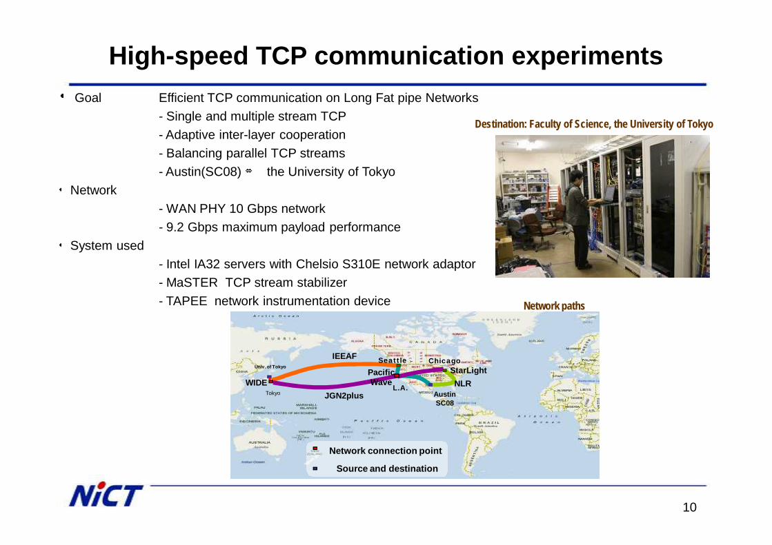
High-speed TCP communication experiments・ Goal Efficient TCP communication on Long Fat pipe Networks
- Single and multiple stream TCP- Adaptive inter-layer cooperation- Balancing parallel TCP streams- Austin(SC08) ⇔ the University of Tokyo
・ Network- WAN PHY 10 Gbps network- 9.2 Gbps maximum payload performance
・ System used- Intel IA32 servers with Chelsio S310E network adaptor- MaSTER TCP stream stabilizer- TAPEE network instrumentation device
Destination: Faculty of Science, the University of Tokyo
Network paths
IEEAF
WIDE
Network connection point
Source and destination
AustinSC08
Tokyo
SeattleUniv. of Tokyo
L.A.JGN2plus
ChicagoPacificWave
StarLightNLR
11
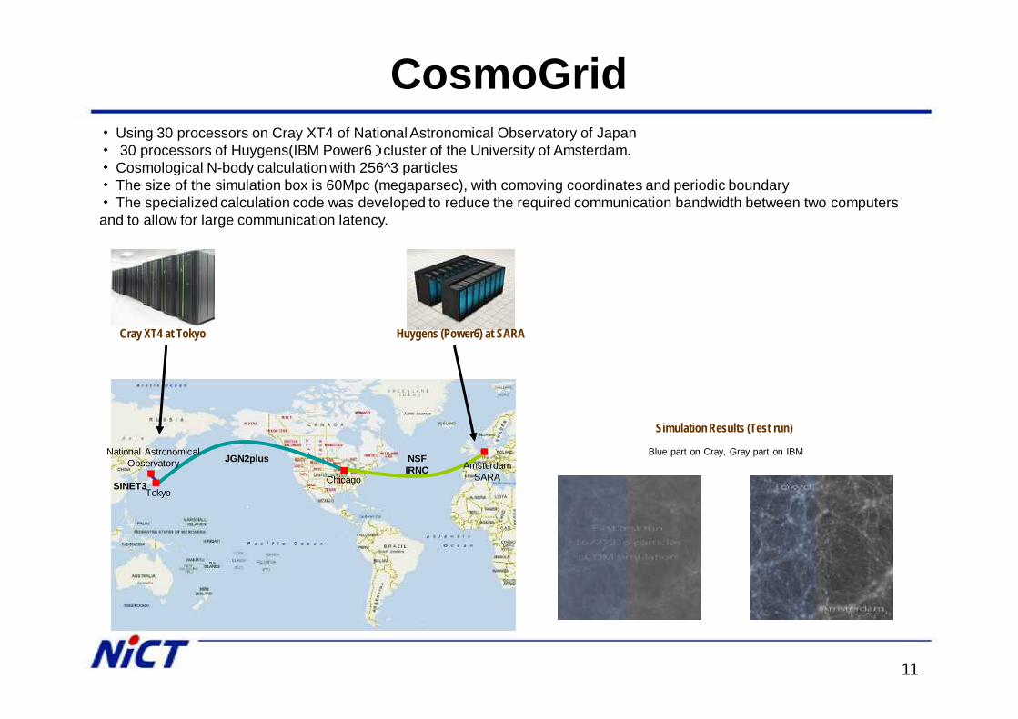
CosmoGrid・ Using 30 processors on Cray XT4 of National Astronomical Observatory of Japan・ 30 processors of Huygens(IBM Power6) cluster of the University of Amsterdam.・ Cosmological N-body calculation with 256^3 particles ・ The size of the simulation box is 60Mpc (megaparsec), with comoving coordinates and periodic boundary・ The specialized calculation code was developed to reduce the required communication bandwidth between two computers and to allow for large communication latency.
Cray XT4 at Tokyo Huygens (Power6) at SARA
AmsterdamSARAChicago
Tokyo
National AstronomicalObservatory
SINET3
JGN2plus NSFIRNC
Simulation Results (Test run)
Blue part on Cray, Gray part on IBM
12
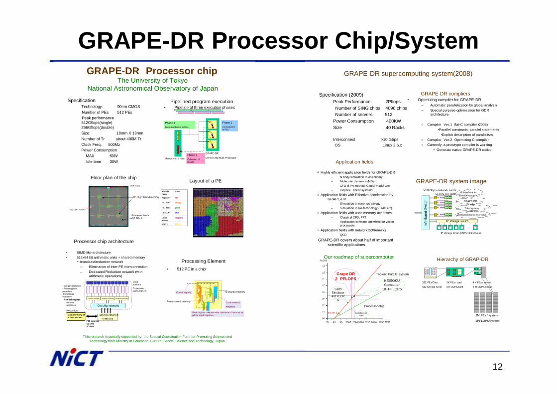
GRAPE-DR Processor Chip/SystemGRAPE-DR Processor chip
SpecificationTechnology: 90nm CMOSNumber of PEs 512 PEsPeak performance 512Gflops(single) 256Gflops(double)Size: 18mm X 18mmNumber of Tr about 400M TrClock Freq. 500Mz Power Consumption
MAX 60WIdle time 30W
Processor chip architecture
External sharedmemory
On chip network
Processingelement)(512)
- Integer operation- Floating point operation-Conditional execution
by mask register
Main memory onA host server
• SIMD like architecture• 512x64 bit arithmetic units + shared memory
+ broadcast/reduction network– Elimination of inter-PE interconnection– Dedicated Reduction network (with
arithmetic operations)Local memory
shared memoryBroadcasting memory accesses
Reduction
Shared memory Shared memory
PCI-express16 laneI/O bus
The University of Tokyo National Astronomical Observatory of Japan
This research is partially supported by the Special Coordination Fund for Promoting Science and Technology from Ministry of Education, Culture, Sports, Science and Technology, Japan.
Processing Element• 512 PE in a chip
Control signals
From shared memory
To shared memory
Local memory
Registers
Mask register・・・Mask write operation of memory by setting mask registers
Pipelined program execution• Pipeline of three execution phases
Phase 1Data distribution to PEs
Phase 3Collection of results
Phase 2Computation in PEs
Memory on a host
GRAPE-DR
Dense Chip Multi-Processor
Floor plan of the chip
Processor block(32 PEs)
ODP module
PLL & DFT module
On chip shared memory
Layout of a PE
Module Name
Color
Register red
Flt. Mul orange
Flt. Add green
Int ALU blue
Local Memo.
magenta
others yellow
GRAPE-DR supercomputing system(2008)
GRAPE-DR system image
PCserver
GRAPE-DR cards
PC server
PC server
PC server
>10 Gbps network cards
IP storage switch
GRAPE-DR compiler
Total system conductor
IP interface forParallel systems
Distributed shared file system
Infin
iban
d Sw
itch
IP storage drives (iSCSI disk drives)
Specification (2009)Peak Performance: 2PflopsNumber of SING chips 4096 chipsNumber of servers 512
Power Consumption 400KWSize 40 Racks
Interconnect >10 GbpsOS Linux 2.6.x
Hierarchy of GRAP-DR
メモリ
512 PEs/Chip
512 GFlops /Chip
2K PEs / card
2TFLOPS/card
4 K PEs / server
4 TFLOPS/server
2M PEs / system
2PFLOPS/system
GRAPE-DR compliers• Optimizing compiler for GRAPE-DR
– Automatic parallelization by global analysis– Special purpose optimization for GDR
architecture
○ Compiler Ver.1 flat-C compiler(2005)・Parallel constructs, parallel statements・Explicit description of parallelism
○ Compiler Ver.2 Optimizing C compiler○ Currently, a prototype compiler is working
・ Generate native GRAPE-DR codes
70 80 90 2000 20102020 2030 2040 2050
Top-end Parallel system
Processor chip
1M
1G
1T
1E
1Z
1Y
1027
1030
FLOPS
1P
Core2Exreme3GHz
Year
EarthSimulator40TFLOP
S
Our roadmap of supercomputer
Grape DR2 PFLOPS
SIGMA-1
Application fields
◎Highly efficient application fields for GRAPE-DR– N-body simulation in Astronomy,– Molecular dynamics(MD)、– CFD(SPH method, Global model)etc.– Linpack, linear systems
○Application fields with Effective acceleration by GRAPE-DR
– Simulation in nano-technology– Simulation in bio-technology (FMO etc)
×Application fields with wide memory accesses– Classical CFD, FFT– Application software optimized for vector
processors×Application fields with network bottlenecks
– QCD
GRAPE-DR covers about half of important scientific applications
KEISOKUComputer
10+PFLOPS
13
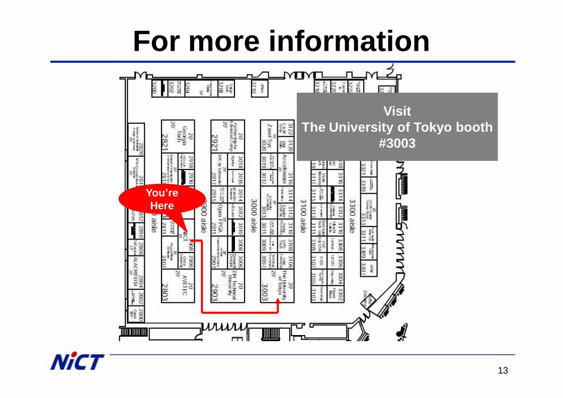
For more information
You’reHere
VisitThe University of Tokyo booth
#3003