bondcharacterizationbetweenconcretesubstrateandrepairing ... ... concrete substrate and concrete...
TRANSCRIPT
ARTICLE IN PRESS
0143-7496/$ - se
doi:10.1016/j.ija
�Correspondfax: +351 253 5
E-mail addr
International Journal of Adhesion & Adhesives 25 (2005) 463–474
www.elsevier.com/locate/ijadhadh
Bond characterization between concrete substrate and repairingSFRC using pull-off testing
Everaldo Bonaldo�, Joaquim A.O. Barros, Paulo B. Lourenc-o
Department of Civil Engineering, University of Minho, Azurem, P 4800-058 Guimaraes, Portugal
Accepted 6 January 2005
Available online 14 March 2005
Abstract
In the last years, an emerging repair and strengthening technique for concrete slabs has been used, consisting of applying a thin
layer of steel fibre reinforced concrete (SFRC) onto the slabs. The performance of the strengthened structural system depends on the
bonding behaviour between old and new concretes. Adhesives based on epoxy resins currently make this liaison. The prices of these
adhesives are quite different depending, mainly, on the percentage of pure resin that they include. In the present paper, three
commercial adhesive compounds of distinct prices and properties were selected to bond concrete substrate and repairing SFRC. The
bond behaviour was assessed from pull-off tests and the influence of the strength class of concrete substrate and repairing SFRC was
analysed. Finally, the performance of the adhesives was evaluated considering both the bond strength and their prices.
r 2005 Elsevier Ltd. All rights reserved.
Keywords: Epoxy/epoxides; Concrete; Fibres; Repair; Pull-off test
1. Introduction
In the last years, the Near Surface Mounted (NSM)strengthening technique has been used, with remarkableefficiency, to increase the flexural [1] and the shearresistance of concrete elements [2]. The NSM techniqueis based on introducing laminate strips of carbon fibrereinforced polymer (CFRP) into slits made on theconcrete cover of the elements to be strengthened. TheNSM technique is well adjusted to increase the flexuralresistance of concrete slabs. However, if the concrete ofthe slab has reduced compression strength, the incre-ment of the flexural resistance that NSM can provide islimited by the maximum allowable compression strain inthe most compressed concrete fibre. As a result of thisrestriction, the maximum tensile stress in the CFRP is alow percentage of its tensile strength, being questionable
e front matter r 2005 Elsevier Ltd. All rights reserved.
dhadh.2005.01.002
ing author. Tel.: +351 253 510 200;
10 217.
ess: [email protected] (E. Bonaldo).
the profitability of this strengthening technique in thesecases. To overcome this limitation, a layer of steel fibrereinforced concrete (SFRC) can be bonded to theexistent concrete at the compression surface, using anadhesive compound [3]. Since a thin layer is enough forthe aforementioned purpose, the shrinkage and thetemperature variation can induce uncontrolled crackingin the concrete of this layer. Adding steel fibres toconcrete, the post-cracking residual stress can beincreased in order to prevent the formation of uncon-trolled crack patterns [4].The bond performance between the existent and
repair concretes plays an important role on the efficacyof this strengthening strategy. The present work dealswith the main aspects related to the bond betweenconcrete of distinct ages and properties, and is part of amore comprehensive research project involving the useof CFRP and discrete steel fibres for the strengtheningand rehabilitation of concrete slabs.The use of thin overlays of cementitious, resinous and
polymer-modified cementitious materials for the
ARTICLE IN PRESSE. Bonaldo et al. / International Journal of Adhesion & Adhesives 25 (2005) 463–474464
strengthening and rehabilitation of concrete pavements,concrete bridges and asphalt pavements is well docu-mented [5–8].The development and maintenance of a sound bond
between the overlay and the existing concrete substrateis an essential requirement to assure high strengtheningperformance. If sufficient adhesion is achieved, thestrengthened structure behaves monolithically, being thematerials effectively being mobilized [6–8].The pull-off test method is one of the tensile test
methods commonly used to assess the adhesion betweenthe repair overlay and the existing concrete substrate.According to the ASTM D4541 standard [9], the generalpull-off test is performed by fixing, with an adhesive, aloading fixture (disk) to the surface of the coating. Afterthe adhesive has hardened, a testing apparatus isattached to the loading fixture and aligned, in order toapply a tensile force normal to the surface to be tested.The force applied to the loading fixture is then graduallyincreased in a manner as smooth and continuous aspossible, using a specified loading rate. Failure occursalong the weakest plan within the system comprised ofthe test fixture, adhesive, repair overlay, bond surfacebetween overlay and substrate, and substrate.Unlike bond test methods of restricted use in
laboratory, the pull-off test can be easily used in thefield evaluation of the bond strength between repairmaterial and parent concrete in a structure. A notablelimitation of this type of test is its relative poorprecision, evidenced by the large variation valuesobtained with different types of apparatus. Since pull-off strength measurements depend on instrumentalparameters, results obtained from different devicesmay not be comparable [7,9].In a concrete patch repair, failures can occur at the
substrate concrete, at the bond interface, at the overlay,at the epoxy used to bond the disk to the core, or as acombination of these failures modes. The mode offailure and the pull-off strength provide valuableinformation about the appropriateness of repair system.The magnitude of the tensile force and the location ofthe fracture surface give some information of theperformance of the repair system (overlay and adhe-sive). When failure only mobilizes adhesion material, thepull-off test provides a true indication of the bondstrength. In this case, the ultimate load is a directmeasure of the adhesion between the overlay and theconcrete substrate. Failures at other locations indicatethat the strength of the adhesive material is larger thanthe tensile strength of the substrate concrete andconcrete overlay. When failure occurs between the diskand the overlay surface, there is an adhesive failure. Inthis case, if the result is lower than the average of theother results, it should be discarded, otherwise it can betaken into account. An epoxy failure should be a rareoccurrence. If failure occurs in the overlay material, the
repair material is the weakest part of the system. This isreferred as a cohesive failure of the overlay. Finally, ifthe fracture surface occurs in the concrete substrate, therepair system can be considered adequate. This is oftenreferred as a cohesive failure of the substrate. In thiscase, the pull-off strength is related to the tensilestrength of the concrete substrate. In some cases, thefailure occurs partially along the bond surface andpartially in either the overlay or concrete substrate, andthe fracture surface is a combination of two or more ofthe aforementioned failures modes [10,11].In [10], a range of bond strength to qualify the test
results is presented: excellent for bond strength X2.1N/mm2, very good for 1.7–2.1N/mm2, good for 1.4–1.7N/mm2, fair 0.7–1.4N/mm2 and poor for bond strengthless than 0.7N/mm2.
2. Scope
This paper presents and analyses the results of anexperimental research program aiming at investigatingthe effect of the strength class of the concrete substrateand the concrete overlay on the adhesion performancebetween these materials. The profitability of threecommercially available bond products was assessed.The influence of the loading rate on the pull-off strengthwas also analysed. The experimental program wascomposed by three test groups, each one of distinctconcrete strength class for the substrate. Each group isconstituted by two series of different concrete strengthclasses for the overlay. To avoid the tendency of thefailure at the lower strength class of the substrate, amaximum difference of one strength class was adoptedfor the concrete of the overlay and the substrate. Theconcrete overlay was always reinforced with steel fibres.Further details regarding the present study can be foundelsewhere [12].
3. Materials
3.1. Bond products
Epoxy resin is widely used to bond materials used inconstruction industry, namely, concrete, masonry units,wood, glass, and metals. Epoxy resin is also a goodadhesive to bond fresh to hardened concrete. Bondingfresh concrete overlay to an existing concrete slab is anexample of such application [13].Three types of epoxy-based bond agents were selected
to bond fresh SFRC overlay to hardened concretesubstrate, namely, two epoxy resin-based products (P1and P2), and one epoxy resin- and cement-basedproduct (P3). Table 1 shows some summarizedinformation about the bond products extracted from
ARTICLE IN PRESSE. Bonaldo et al. / International Journal of Adhesion & Adhesives 25 (2005) 463–474 465
manufacturer guidelines [14]. The bond P1 and P2coating materials were applied onto dry and cleanconcrete, i.e., free from surface contaminants such asdust, laitance, oil or grease, following the manufac-turer’s specifications. To evaluate the influence of thesurface conditions on the bond coat material, P3 wasapplied onto two types of substrate surface: dry surfaceand saturated surface. Since the manufacturer recom-mends applying the bond coat material P3 on saturatedsurface, the dry surface state was aimed at reproducingthe real situation, verified in construction plants, wheresometimes saturated condition is not completelyguaranteed. The proportions adopted for each compo-nent are in agreement with the manufacturer’s specifica-tions [14].
3.2. Concrete substrate and concrete overlay
Using the Faury concrete mix design method [15]C16/20, C35/45 and C55/67 strength concrete classeswere designed for the substrate, and C20/25, C25/30,C35/45, C45/55, C55/67 and C60/75 strength classes ofSFRC were conceived for the overlay. All the strengthconcrete classes were classified according to CEB-FIP[16] concrete grades. Untreated aggregates, available inthe Northern Region of Portugal (Minho), were used inthe composition of concretes. To reinforce the concreteoverlay hooked ends DRAMIXs RC-80/60-BN steelfibres were used, this fibre has a length (lf) of 60mm, adiameter (df) of 0.75mm, an aspect-ratio (lf/df) of 80 anda yield strength of about 1100N/mm2 [17]. In previousworks it was verified that this fibre has high performancesince significant increase in the ultimate load bearingcapacity of the structural concrete elements wasobtained [18,19].Table 2 shows the mix proportion of the designed
concretes and their main properties. The Rheobuilds
1000 superplasticizer of MBT is a weight percentage ofthe binder (cement, C, in the concrete substrates; andcement and fly ash, FA, in the concretes for the overlay).It is noted that with very few exceptions the obtainedcompressive value is adequate with respect to theplanned concrete class.
4. Test set-up
4.1. Preparation of the specimens
Unreinforced concrete slabs of 300mm� 650mm,with 80mm thickness, were used as concrete substrate.For each batch of concrete, three cylindrical concretespecimens, measuring 150mm in diameter and 300mmlong, were cast. Burlap sacks were placed over the slabsand specimens and were maintained wet for 2 days.After this curing phase, the slabs and the cylindrical
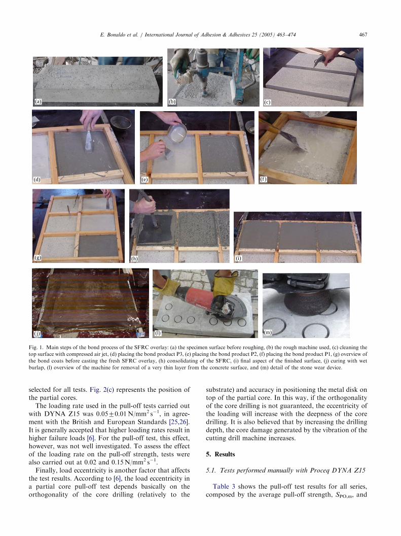
specimens were demoulded and maintained in normallaboratory conditions. When the concrete substrateattained 28 days of age, the top surface (casting surface)of the slab specimen was treated. Fig. 1(a) and (b) showa specimen before surface treatment and the equipmentused to rough the surface. The process of roughing thetop surface of the concrete substrate has the purpose ofremoving a very thin layer of the surface, in order toremove grease, oils, free particles, laitance or dirt, aswell as producing an irregular surface. The bondproduct was then applied and the fresh concrete overlaywas cast (see Fig. 1). The procedures to bond the freshSFRC overlay to the hardened concrete were inaccordance to the manufacturer’s specifications [14]and the ACI guidelines [20–22]. Previous researchdealing with the combined use of CFRP and SFRCmaterials for structural strengthening has shown that athickness of 30mm for the SFRC overlay can be veryeffective [3]. Therefore, in the present work, thisthickness was considered for the SFRC overlay. Toconsolidate the SFRC overlay, a mini slipform paverwas used (see Fig. 1(h)). The mini slipform intends tosimulate the real conditions of compaction of a thinSFRC overlay. Similarly to the substrate concrete, threecylindrical concrete specimens (150mm� 300mm) foreach batch of SFRC were cast and tested in compressionat 28 days of age. The aforementioned curing processwas also followed for the thin SFRC overlay andcylindrical concrete specimens. When the concreteoverlay attained an age of about 28 days, the partialcore was drilled and the pull-off tests were carried out.
4.2. Pull-off test method and equipment
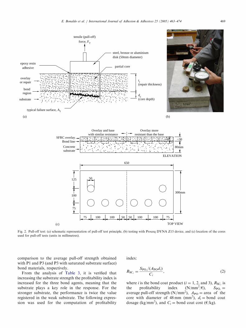
When compared to other tests, the pull-off test is thesimplest and most popular tensile bond test (see Fig.2(a)) for measuring the adhesion properties, both on sitefor quality control and, in the laboratory, to evaluatethe material properties and failure modes [6,7,23]. Toevaluate the adhesion strength of an adhesive materialthat bonds a concrete overlay to an existing concretesubstrate, the pull-off test with a partial coringtechnique is usual. However, this test can be affectedby some factors such as the coring depth into substrate,the floor thickness and the strength class of the concretesubstrate [23].As mentioned previously, the pull-off test involves the
application of a direct tensile load (FT) to a partial corethat mobilizes the repair material, the bond line and aportion of the substrate until failure occurs. The tensileload is applied to the partial core through the use of ametal, bronze or aluminium disk with a pull pin, bondedto the overlay with an epoxy resin. A loading device,with a reaction frame, applies the load to the pull pin ata constant rate. After performing the test, the failuremode has to be carefully analysed since it provides
ARTICLE IN PRESS
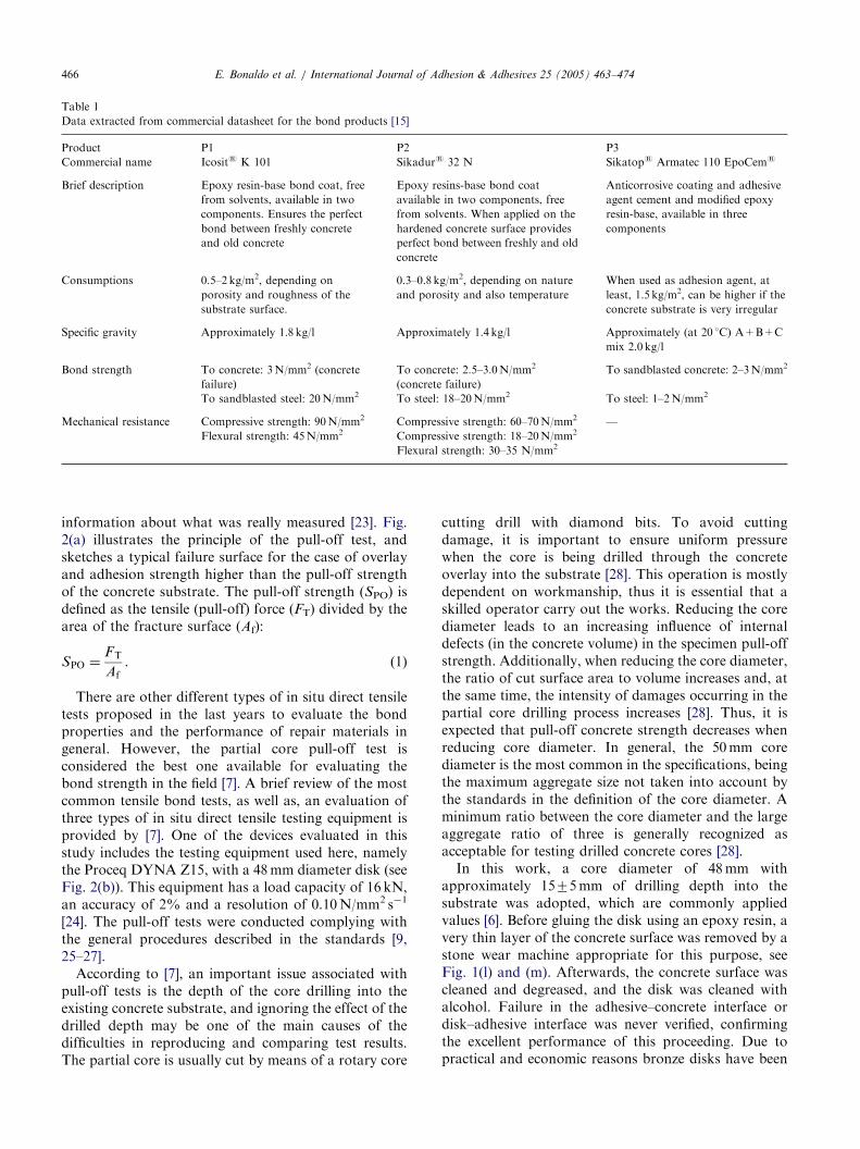
Table 1
Data extracted from commercial datasheet for the bond products [15]
Product P1 P2 P3
Commercial name Icosits K 101 Sikadurs 32 N Sikatops Armatec 110 EpoCems
Brief description Epoxy resin-base bond coat, free
from solvents, available in two
components. Ensures the perfect
bond between freshly concrete
and old concrete
Epoxy resins-base bond coat
available in two components, free
from solvents. When applied on the
hardened concrete surface provides
perfect bond between freshly and old
concrete
Anticorrosive coating and adhesive
agent cement and modified epoxy
resin-base, available in three
components
Consumptions 0.5–2 kg/m2, depending on
porosity and roughness of the
substrate surface.
0.3–0.8 kg/m2, depending on nature
and porosity and also temperature
When used as adhesion agent, at
least, 1.5 kg/m2, can be higher if the
concrete substrate is very irregular
Specific gravity Approximately 1.8 kg/l Approximately 1.4 kg/l Approximately (at 20 1C) A+B+C
mix 2.0 kg/l
Bond strength To concrete: 3N/mm2 (concrete
failure)
To concrete: 2.5–3.0N/mm2
(concrete failure)
To sandblasted concrete: 2–3N/mm2
To sandblasted steel: 20N/mm2 To steel: 18–20N/mm2 To steel: 1–2N/mm2
Mechanical resistance Compressive strength: 90N/mm2 Compressive strength: 60–70N/mm2 —
Flexural strength: 45N/mm2 Compressive strength: 18–20N/mm2
Flexural strength: 30–35 N/mm2
E. Bonaldo et al. / International Journal of Adhesion & Adhesives 25 (2005) 463–474466
information about what was really measured [23]. Fig.2(a) illustrates the principle of the pull-off test, andsketches a typical failure surface for the case of overlayand adhesion strength higher than the pull-off strengthof the concrete substrate. The pull-off strength (SPO) isdefined as the tensile (pull-off) force (FT) divided by thearea of the fracture surface (Af):
SPO ¼FT
Af. (1)
There are other different types of in situ direct tensiletests proposed in the last years to evaluate the bondproperties and the performance of repair materials ingeneral. However, the partial core pull-off test isconsidered the best one available for evaluating thebond strength in the field [7]. A brief review of the mostcommon tensile bond tests, as well as, an evaluation ofthree types of in situ direct tensile testing equipment isprovided by [7]. One of the devices evaluated in thisstudy includes the testing equipment used here, namelythe Proceq DYNA Z15, with a 48mm diameter disk (seeFig. 2(b)). This equipment has a load capacity of 16 kN,an accuracy of 2% and a resolution of 0.10N/mm2 s�1
[24]. The pull-off tests were conducted complying withthe general procedures described in the standards [9,25–27].According to [7], an important issue associated with
pull-off tests is the depth of the core drilling into theexisting concrete substrate, and ignoring the effect of thedrilled depth may be one of the main causes of thedifficulties in reproducing and comparing test results.The partial core is usually cut by means of a rotary core
cutting drill with diamond bits. To avoid cuttingdamage, it is important to ensure uniform pressurewhen the core is being drilled through the concreteoverlay into the substrate [28]. This operation is mostlydependent on workmanship, thus it is essential that askilled operator carry out the works. Reducing the corediameter leads to an increasing influence of internaldefects (in the concrete volume) in the specimen pull-offstrength. Additionally, when reducing the core diameter,the ratio of cut surface area to volume increases and, atthe same time, the intensity of damages occurring in thepartial core drilling process increases [28]. Thus, it isexpected that pull-off concrete strength decreases whenreducing core diameter. In general, the 50mm corediameter is the most common in the specifications, beingthe maximum aggregate size not taken into account bythe standards in the definition of the core diameter. Aminimum ratio between the core diameter and the largeaggregate ratio of three is generally recognized asacceptable for testing drilled concrete cores [28].In this work, a core diameter of 48mm with
approximately 1575mm of drilling depth into thesubstrate was adopted, which are commonly appliedvalues [6]. Before gluing the disk using an epoxy resin, avery thin layer of the concrete surface was removed by astone wear machine appropriate for this purpose, seeFig. 1(l) and (m). Afterwards, the concrete surface wascleaned and degreased, and the disk was cleaned withalcohol. Failure in the adhesive–concrete interface ordisk–adhesive interface was never verified, confirmingthe excellent performance of this proceeding. Due topractical and economic reasons bronze disks have been
ARTICLE IN PRESS
(m)(l)( j)
(g) (h) (i)
(f )(e)(d)
(c)(b)(a)
Fig. 1. Main steps of the bond process of the SFRC overlay: (a) the specimen surface before roughing, (b) the rough machine used, (c) cleaning the
top surface with compressed air jet, (d) placing the bond product P3, (e) placing the bond product P2, (f) placing the bond product P1, (g) overview of
the bond coats before casting the fresh SFRC overlay, (h) consolidating of the SFRC, (i) final aspect of the finished surface, (j) curing with wet
burlap, (l) overview of the machine for removal of a very thin layer from the concrete surface, and (m) detail of the stone wear device.
E. Bonaldo et al. / International Journal of Adhesion & Adhesives 25 (2005) 463–474 467
selected for all tests. Fig. 2(c) represents the position ofthe partial cores.The loading rate used in the pull-off tests carried out
with DYNA Z15 was 0.0570.01N/mm2 s�1, in agree-ment with the British and European Standards [25,26].It is generally accepted that higher loading rates result inhigher failure loads [6]. For the pull-off test, this effect,however, was not well investigated. To assess the effectof the loading rate on the pull-off strength, tests werealso carried out at 0.02 and 0.15N/mm2 s�1.Finally, load eccentricity is another factor that affects
the test results. According to [6], the load eccentricity ina partial core pull-off test depends basically on theorthogonality of the core drilling (relatively to the
substrate) and accuracy in positioning the metal disk ontop of the partial core. In this way, if the orthogonalityof the core drilling is not guaranteed, the eccentricity ofthe loading will increase with the deepness of the coredrilling. It is also believed that by increasing the drillingdepth, the core damage generated by the vibration of thecutting drill machine increases.
5. Results
5.1. Tests performed manually with Proceq DYNA Z15
Table 3 shows the pull-off test results for all series,composed by the average pull-off strength, SPO,m, and
ARTICLE IN PRESS
Table 2
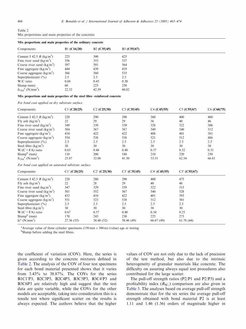
Mix proportions and main properties of the concretes
Mix proportions and main properties of the ordinary concrete
Components B1 (C16/20) B2 (C35/45) B3 (C55/67)
Cement I 42.5 R (kg/m3) 225 300 425
Fine river sand (kg/m3) 356 353 337
Coarse river sand (kg/m3) 597 591 564
Fine aggregate (kg/m3) 444 439 419
Coarse aggregate (kg/m3) 566 560 535
Superplasticizer (%) 2.5 2.5 2.5
W/C ratio 0.68 0.45 0.30
Slump (mm) 60 225 250
fc28da (N/mm2) 22.32 42.59 60.82
Mix proportions and main properties of the steel fibre -reinforced concrete
For bond coat applied on dry substrate surface
Components C1 (C20/25) C2 (C25/30) C3 (C35/45) C4 (C45/55) C5 (C55/67) C6 (C60/75)
Cement I 42.5 R (kg/m3) 220 290 290 360 400 460
Fly ash (kg/m3) 22 29 29 36 40 46
Fine river sand (kg/m3) 349 339 339 328 322 306
Coarse river sand (kg/m3) 584 567 567 549 540 512
Fine aggregate (kg/m3) 434 422 422 408 401 381
Coarse aggregate (kg/m3) 554 538 538 521 512 486
Superplasticizer (%) 2.5 2.5 2.5 2.5 2.5 2.5
Steel fibre (kg/m3) 30 30 30 30 30 30
W/(C+FA) ratio 0.65 0.48 0.48 0.37 0.32 0.31
Slumpb (mm) 110 200 180 210 220 250
fc28da (N/mm2) 25.87 32.08 41.50 53.51 62.54 66.81
For bond coat applied on saturated substrate surface
Components C10 (C20/25) C20 (C25/30) C30 (C35/45) C40 (C45/55) C50 (C55/67)
Cement I 42.5 R (kg/m3) 220 280 290 400 475
Fly ash (kg/m3) 22 28 29 40 48
Fine river sand (kg/m3) 347 329 339 322 315
Coarse river sand (kg/m3) 581 552 567 540 528
Fine aggregate (kg/m3) 432 410 422 401 393
Coarse aggregate (kg/m3) 551 523 538 512 501
Superplasticizer (%) 2.5 2.5 2.5 2.5 2.5
Steel fibre (kg/m3) 30 30 30 30 30
W/(C+FA) ratio 0.67 0.57 0.48 0.34 0.25
Slumpb (mm) 170 245 230 225 275
fca (N/mm2) 27.36 (55) 38.48 (52) 58.46 (49) 66.67 (49) 61.78 (44)
aAverage value of three cylinder specimens (150mm� 300m) (value) age at testing.bSlump before adding the steel fibres.
E. Bonaldo et al. / International Journal of Adhesion & Adhesives 25 (2005) 463–474468
the coefficient of variation (COV). Here, the series isgiven according to the concrete mixtures defined inTable 2. The analysis of the COV of four test specimensfor each bond material presented shows that it variesfrom 3.43% to 38.87%. The COVs for the seriesB1C10P3, B2C3P3, B2C4P3, B3C5P3, B3C40P3 andB3C6P3 are relatively high and suggest that the testdata are quite variable, while the COVs for the othermodels are acceptable, taking into consideration this is atensile test where significant scatter on the results isalways expected. The authors believe that the higher
values of COV are not only due to the lack of precisionof the test method, but also due to the intrinsicheterogeneity of granular materials like concrete. Thedifficulty on assuring always equal test procedures alsocontributed for the large scatter.The pull-off strength ratios (P2/P1 and P2/P3) and a
profitability index ðRSCiÞ comparison are also given in
Table 3. The analyses based on average pull-off strengthdemonstrate that for the six series the average pull-offstrength obtained with bond material P2 is at least1.11 and 1.46 (1.36) orders of magnitude higher in
ARTICLE IN PRESS
(a) (b)
epoxy resin adhesive
overlay or repair
bond region
substrate
typical failure surface, Af
tr (repair thickness)
ds (core depth)
partial core
steel, bronze or aluminium disk (50mm diameter)
tensile (pull-off)
force, FT
45
Overlay and base with similar resistance
Overlay more resistant than the base
SFRC overlay Bond line
Concrete substrate
ELEVATION
80mm
~30
75 75
650
125
100
100 100 100 100
50
50 50
75
300mm
TOP VIEW(c)
Fig. 2. Pull-off test: (a) schematic representation of pull-off test principle, (b) testing with Proceq DYNA Z15 device, and (c) location of the cores
used for pull-off tests (units in millimetres).
E. Bonaldo et al. / International Journal of Adhesion & Adhesives 25 (2005) 463–474 469
comparison to the average pull-off strength obtainedwith P1 and P3 (and P3 with saturated substrate surface)bond materials, respectively.From the analysis of Table 3, it is verified that
increasing the substrate strength the profitability index isincreased for the three bond agents, meaning that thesubstrate plays a key role in the response. For thestronger substrate, the performance is twice the valueregistered in the weak substrate. The following expres-sion was used for the computation of profitability
index:
RSCi¼
SPOi=ðAPOdiÞ
Ci
, (2)
where i is the bond coat product (i ¼ 1; 2, and 3), RSCiis
the profitability index (N/mm2/h), SPOi¼
average pull-off strength ðN=mm2Þ; APO ¼ area of thecore with diameter of 48mm (mm2), di ¼ bond coatdosage (kg/mm2), and Ci ¼ bond coat cost (h/kg).

ARTICLE IN PRESS
Table 3
Average pull-off strength, strength ratio and profitability index
Series Average pull-off strength, SPO,m (N/mm2) Strength ratio Profitability index (N/mm2/h)a
Bond product
P1 P2 P3 P2/P1 P2/P3 RSC1 RSC2 RSC3
B1C1 1.48 (9.46) 1.58 (11.39) 1.12 (8.04) 1.07 1.41 119 674 38
1.35(1) (22.25) 1.17(1) 46
B1C2 1.61 (12.42) 1.83 (15.30) 1.36 (11.76) 1.14 1.35 130 780 47
1.43(2) (17.46) 1.28(2) 49
B2C3 2.46 (15.04) 2.59 (6.56) 1.69 (24.26) 1.05 1.53 198 1104 58
2.22(3) (16.10) 1.17(3) 76
B2C4 2.38 (18.07) 2.35 (11.91) 1.61 (24.84) 0.99 1.46 191 1002 55
1.81(4) (13.22) 1.30(4) 62
B3C5 3.21 (3.43) 4.20 (6.43) 2.83 (22.97) 1.31 1.48 258 1791 97
2.57(5) (20.51) 1.63(5) 88
B3C6 3.32 (15.66) 3.73 (7.77) 2.47 (38.87) 1.12 1.51 267 1590 85
2.36(6) (15.51) 1.58(6) 81
Average 1.11 1.46
1.36
(1)B1C10, (2)B1C20, (3)B2C20, (4)B2C30, (5)B3C40, (6)B3C50 (value) coefficient of variation (COV) ¼ (standard deviation/average)� 100.aTaking into account the bond coat dosage and the area of the core. The prices were provided by the manufacturer (P1: 3.04 h/Kg; P2: 1.44 h/Kg;
P3: 5.09h/Kg).
P1P2P3P3*
Pull-
off
stre
ngth
(N
/mm
2 )
4.5
4.0
3.5
3.0
2.5
2.0
1.5
1.0
0.5
0.0
Substrate and overlay with the same resistance Overlay more resistant than the substrate
SUBSTRATE/OVERLAY
B1C1[C1'] B2C3[C2'] B3C5[C4'] B1C2[C2'] B2C4[C3'] B3C6[C5']
Fig. 3. Pull-off average strength for each substrate and overlay type
(where P3* indicates bond P3 applied on saturate substrate surface).
E. Bonaldo et al. / International Journal of Adhesion & Adhesives 25 (2005) 463–474470
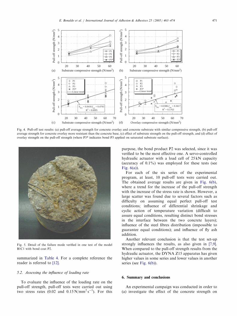
The average pull-off strength values of four pull-offtests with DYNA Z15 device are depicted in Fig. 3, forall series. It can be observed that increasing the strengthof the overlay does not lead to an increase in the pull-offstrength, as expected. On the contrary, the strength ofthe substrate plays a major role in the pull-off strength.From the experimental data, it is also possible toobserve that the pull-off strength for bond product P3 isrelatively low in comparison with the results for P1 andP1, meaning that the bond product plays a role in theresponse. P2 bond product attained larger average pull-off strengths than the other bond products, indepen-dently of the substrate and overlay compressive strength(see Fig. 4(a) and (b)). Fig. 4(c) and (d) indicate linearincreasing trend of pull-off strength with the compres-sive strength of concrete substrate and SFRC overlay.
A marginal benefit is verified when the bond coatproduct P3 is applied on saturated substrate surface forthe cases of low and medium concrete class strength ofthe substrate (models B1C10, B1C20, B2C20 and B2C30).For the case of high concrete class strength of thesubstrate (models B3C40 and B3C50), a reduction in thepull-off strength was observed (see Fig. 4(a) and (b)).The substrate of these series was made using the highestconcrete strength class, which offered higher resistanceto the penetration of the water used to saturate thesubstrate surface, resulting in the formation of a waterfilm that has decreased the bond strength between thetwo concrete materials.Finally, the better profitability index was obtained for
the bond coat material P2, independently of thesubstrate and overlay compressive strength.As an example of the complex response of the pull-off
test, Fig. 5 shows the fracture surface of core 2 of themodel B1C1P2 (see [12]). The crack surface was initiatedin the interface adhesive–concrete overlay from the zonewhere high percentage of voids and network voids werevisible. This exceptional high percentage of voids mightbe related to the agglomeration and non-favourablefibre orientation. In spite of this apparent weakness, thepull-off strength of this specimen was the highest one ofthe specimens of its series. This extraneous result mightbe justified by the crack surface profile. In fact, afterinitiation at the adhesive–concrete overlay interface, thecrack surface has crossed the adhesive layer, that hastensile strength much higher than the surroundingconcrete materials, and ending at the concrete substrate,resulting in a tortuous crack surface profile of highersurface. All failure modes of the testing programme are
ARTICLE IN PRESS
0
1
2
3
4
5
P1 P2 P3 P3*
20 30 40 50 600
1
2
3
4
5
P1 P2 P3 P3*
20 30 40 50 60 70 20 30 40 50 60 700
1
2
3
4
5 P1 P2 P3 P3*
0
1
2
3
4
5 P1 P2 P3 P3*
Pul
l-of
f st
reng
th (
N/m
m2 )
Substrate compressive strength (N/mm2)
Pul
l-of
f st
reng
th (
N/m
m2 )
20 30 50 6040Substrate compressive strength (N/mm2)
Pull-
off
stre
ngth
(N
/mm
2 )
SPO
= 0.0418 fcm
+ 0.4793
R2 = 0.6995
SPO
= 0.0386 fcm
+ 0.3617
R2 = 0.5763
Substrate compressive strength (N/mm2) Overlay compressive strength (N/mm2)Pu
ll-of
f st
reng
th (
N/m
m2 )
Linear trend Linear trend
(a)
(c) (d)
(b)
Fig. 4. Pull-off test results: (a) pull-off average strength for concrete overlay and concrete substrate with similar compressive strength, (b) pull-off
average strength for concrete overlay more resistant than the concrete base, (c) effect of substrate strength on the pull-off strength, and (d) effect of
overlay strength on the pull-off strength (where P3* indicates bond P3 applied on saturated substrate surface).
Fig. 5. Detail of the failure mode verified in one test of the model
B1C1 with bond coat P2.
E. Bonaldo et al. / International Journal of Adhesion & Adhesives 25 (2005) 463–474 471
summarized in Table 4. For a complete reference thereader is referred to [12].
5.2. Assessing the influence of loading rate
To evaluate the influence of the loading rate on thepull-off strength, pull-off tests were carried out usingtwo stress rates (0.02 and 0.15N/mm2 s�1). For this
purpose, the bond product P2 was selected, since it wasverified to be the most effective one. A servo-controlledhydraulic actuator with a load cell of 25 kN capacity(accuracy of 0.1%) was employed for these tests (seeFig. 6(a)).For each of the six series of the experimental
program, at least, 10 pull-off tests were carried out.The obtained average results are given in Fig. 6(b),where a trend for the increase of the pull-off strengthwith the increase of the stress rate is shown. However, alarge scatter was found due to several factors such asdifficulty on assuming equal perfect pull-off testconditions; influence of differential shrinkage andcyclic action of temperature variation (difficult toassure equal conditions, resulting distinct bond stressesin the interface between the two concrete layers);influence of the steel fibres distribution (impossible toguarantee equal conditions); and influence of fly ashaddition.Another relevant conclusion is that the test set-up
strongly influences the results, as also given in [7,9].When compared to the pull-off strength results from thehydraulic actuator, the DYNA Z15 apparatus has givenhigher values in some series and lower values in anotherseries (see Fig. 6(b)).
6. Summary and conclusions
An experimental campaign was conducted in order to(a) investigate the effect of the concrete strength on

ARTICLE IN PRESS
Table 4
Summary of the modes of failure
Model Bond product Failure mode recorded
B1C1 1 Combination of substrate failure, aggregate-paste bond failure and paste failure. Existence of voids on
the fracture surface2
3 Failure in the bond–substrate interface
3(1) Substrate failure just below the bond–substrate interface (combination of paste failure, aggregate
failure and aggregate-paste bond failure), and bond–overlay interface failure (in the high spots part of
the substrate surface, i.e. in the stand out part of the coarse aggregates)
B1C2 1 Combination of substrate failure, aggregate-paste bond failure and paste failure. Existence of voids on
the fracture surface
2 Combination of substrate failure, aggregate-paste bond failure, coarse aggregate failure and paste
failure. Existence of voids on the fracture surface
3 Failure in the bond–substrate interface
3(2) Substrate failure just below the bond–substrate interface (combination of paste failure, aggregate
failure and aggregate-paste bond failure), and bond–overlay interface failure (in the high spots part of
the substrate surface, i.e. in the stand out part of the coarse aggregates). Existence of voids on the
fracture surface
B2C3 1 Combination of substrate failure, aggregate-paste bond failure and paste failure. Existence of voids on
the fracture surface
2 Failure in the substrate concrete just bellow the bond–substrate interface (top surface of substrate),
aggregate-paste bond failure, coarse aggregate failure and paste failure. Existence of voids on the
fracture surface
3 Failure in the bond–substrate interface.
3(3) Substrate failure just below the bond–substrate interface (combination of paste failure and aggregate
failure), and bond–overlay interface failure (in the high spots part of the substrate surface, i.e. in the
stand out part of the coarse aggregates)
B2C4 1 Combination of substrate failure, aggregate-paste bond failure and paste failure. Existence of voids on
the fracture surface
2 Failure in the substrate concrete just bellow the bond–substrate interface (top surface of substrate),
aggregate-paste bond failure, coarse aggregate failure and paste failure. Existence of voids on the
fracture surface
3 Failure in the bond–substrate interface
3(4) Failure in the bond–overlay interface (located in the high spots part of the substrate surface, i.e. in the
stand out part of the coarse aggregates. A uniform bond-line thickness was not kept. Probably the
remaining water coat of the water used to saturated the surface changed the bond coat thixotropy and
the adhesive drained away from the high spots and into the low spots) and failure in the bond–substrate
interface (levelling to the top substrate surface in the paste and also in the coarse aggregates)
B3C5 1 Failure in the substrate concrete just bellow the bond–substrate interface (top surface of substrate),
coarse aggregate failure and paste failure. Presence of voids on the fracture surface
2 Combination of substrate failure, bond-substrate failure, overlay failure and overlay–bond interface
failure. Existence of voids on the fracture surface
3 Failure in the overlay–bond interface. Existence of voids on the fracture surface
3(5) Bond–substrate interface failure and bond–overlay interface failure (in the high spots part of the
substrate surface, i.e. in the stand out part of the coarse aggregates
B3C6 1 Combination of substrate failure, just bellow the bond-substrate interface (top surface of substrate),
aggregate-paste bond failure, coarse aggregate failure and paste failure. Existence of voids on the
fracture surface
2 Combination of substrate failure, overlay–bond interface failure (presence of fibres in this region).
Existence of voids on the fracture surface
3 Combination of bond–substrate interface failure, overlay–bond interface failure. Existence of voids on
the fracture surface
3(6) Bond–substrate interface failure and bond–overlay interface failure (in the high spots part of the
substrate surface, i.e. in the stand out part of the coarse aggregates
(1)B1C10, (2)B1C20, (3)B2C20, (4)B2C30, (5)B3C40, (6)B3C50.
E. Bonaldo et al. / International Journal of Adhesion & Adhesives 25 (2005) 463–474472
bond strength between concrete substrate and concreteoverlay, (b) evaluate the bond performance of threecommercially available bond agents, denoted as P1, P2and P3, and (c) assess the effect of the loading rate on
the pull-off strength. For this purpose, a total of 285partial-depth cores were tested.In general, all series have showed a large scatter in the
pull-off tensile strength. Nevertheless, all bond coat

ARTICLE IN PRESS
(a)
(b)
Pull-
off
stre
ngth
(N
/mm
2 )
0.0
0.5
1.0
1.5
2.0
2.5
3.0
3.5
4.0
4.5
B1C1 B1C2 B2C3 B2C4 B3C5 B3C6
Group
Proceq DYNA Z15
0.02 N/mm2/s0.15 N/mm2/s
Fig. 6. Influence of loading rate on the pull-off strength: (a) pull-off
test set-up for controlled loading rate and (b) comparison of the pull-
off strength for different stress rates.
E. Bonaldo et al. / International Journal of Adhesion & Adhesives 25 (2005) 463–474 473
materials exhibited average pull-off strengths higherthan 1.12N/mm2. For the concrete substrate of low andmedium strength, bonded by P1 or P2 adhesives, therewas a clear tendency for concrete substrate failure,which indicates that the substrate concrete was generallythe weakest link in the repair system. In this way, thepull-off strength reflects the tensile strength of theconcrete substrate.For P1 and P2 bond materials, the thin SFRC overlay
was well bonded to the concrete substrate, and thetensile strength of the overlay has exceeded the tensilestrength of the concrete substrate. Evidence of voids andnon-uniform steel fibres distribution was observed insome failure surfaces, suggesting that additional atten-tion should be given to the consolidating procedures ofthe SFRC mixture.The shape, maximum diameter and strength of coarse
aggregates seem to play an important role in the pull-offstrength, as for substrate of low and medium strength
the crack surface developed at the interface coarseaggregate–cement paste, while at substrates of highconcrete strength the coarse aggregate was also crossedby the failure surface.In general, the failure surface was located at the top of
the substrate concrete, just below the bond adhesive.The lower resistance of the top surface of the substratemight explain this behaviour. The procedure carried outin the preparation of this zone might have beenresponsible for part of this weakness.The bond product P2 provided the highest pull-off
strength values and, according to the manufacturer, wasthe more economical, being the best bond product forthis type of application.The results indicate also a trend for an increase of the
pull-off strength with the increase of the loading rate,and confirm the difficulty in comparing the results usingdifferent test set-ups.
Acknowledgements
The authors acknowledge the financial support of thePortuguese Science and Technology Foundation (FCT),PhD Grant number SFRH/BD/11232/2002. Acknowl-edgements are also extended to the companies ‘‘Com-panhia Geral de Cal e Cimento S.A. (SECIL)’’, SikaS.A., ‘‘Central do Pego’’, ‘‘Pedreiras Bezerras’’, BekaertNV, ‘‘Bettor MBT Portugal Produtos Quımicos paraConstruc- ao S.A.’’, that have supplied cement, bondproducts, fly ash, aggregates, steel fibres and super-plasticizer, respectively.
References
[1] Barros JAO, Fortes AS. Flexural strengthening of concrete beams
with CFRP laminates bonded into slits. J Cem Concr Compos
2005;27:471–80.
[2] Barros JAO, Dias SJE. Shear strengthening of reinforced concrete
beams with laminate strips of CFRP. Proceedings of the
international conference composites in constructions—
CCC2003, Cosenza, Italy, 16–19 September 2003. p. 289–94.
[3] Barros JAO, Sena-Cruz JM. Strengthening a prestressed concrete
slab by epoxy-bonded FRP composites and SFRC overlayer.
Proceedings of the seventh international conference on inspection
appraisal repairs & maintenance of buildings & structures,
Nottingham Trent University, UK, 11–13 September 2001.
[4] Barros JAO, Cunha VMCF, Ribeiro AF, Antunes JAB. Post-
cracking behaviour of steel fibre reinforced concrete. RILEM,
Mater Struct 2005;38:47–56.
[5] Knab LI. Factors related to the performance of concrete repair
materials, Technical report REMR-CS-12, US Army Corps of
Engineers, Washington, DC, March 1988.
[6] Austin S, Robins P, Pan V. Tensile bond testing of concrete
repairs. RILEM, Mater Struct 1995;28:249–59.
[7] Vaysburd AM, MacDonald JE. An evaluation of equipment and
procedures for tensile bond testing of concrete repairs. Technical
report REMR-CS-61, US Army Corps of Engineers, Washington,
DC, June 1999.
ARTICLE IN PRESSE. Bonaldo et al. / International Journal of Adhesion & Adhesives 25 (2005) 463–474474
[8] Delatte N, Sehdev A. Mechanical properties and durability of
BCO and UTW concrete. Proceedings of annual meeting of the
TRB, 82th, Washington, DC, January 2003.
[9] ASTM D4541. Standard test method for pull-off strength of
coating using portable adhesion testers. American Society for
Testing and Materials; 2002.
[10] Sprinkel MM, Ozyildirim C. Evaluation of high performance
concrete overlays placed on Route 60 over Lynnhaven Inlet in
Virginia. Final report, Virginia Transportation Research Council,
Charlottesville, Virginia, 2000.
[11] FHA—Federal Highway Administration. Tensile bond strength
of a high performance concrete bridge deck overlay. Field test
report, Mobile Concrete Library Project # 9904, US Department
of Transportation home page, 2000. http://www.fhwa.dot.gov/
pavement/mcl9904.pdf (available on March 21, 2003).
[12] Bonaldo E, Barros JAO, Lourenc-o PB. Bond characterization
between concrete base and repairing SFRC by pull-off tests.
Report 04-DEC/E-13, University of Minho, May 2004, 57pp.
[13] ACI 503R. Use of epoxy compounds with concrete. ACI manual
of concrete practice, Part 5, Reported by Committee 503.
American Concrete Institute; 1993 28pp [Reapproved 1998].
[14] Sika. Technical data sheet—construction. Sika—Chemical In-
dustry, S.A., Edition no. 5, 2002. 434pp [in Portuguese].
[15] Faury J. Le Beton. Troisieme Edition. Paris: Dunod; 1958.
[16] CEB-FIP Model Code 1990. Design code. Comite Euro-Interna-
tional du Beton, Bulletins d’Information 203-205, Lausanne,
Switzerland, 1993.
[17] Dramix: product data sheet. N. V. Bekaert S.A., 1998.
[18] Barros JAO. Steel fibre reinforced concrete behaviour—experi-
mental analysis and numerical simulation. PhD thesis, Faculty of
Engineering, University of Porto, 1995 [in Portuguese].
[19] Barros JAO, Figueiras JA. Experimental behaviour of fibre
concrete slabs on soil. J Mech Cohesive-frict Mater
1998;3:277–90.
[20] ACI 503.2. Standard specification for bonding plastic concrete to
hardened concrete with a multi-component epoxy adhesive. ACI
manual of concrete practice, Part 5, Reported by Committee 503.
American Concrete Institute; 1992 5pp [Reapproved 1997].
[21] ACI 503.5R. Guide for the selection of polymer adhesives with
concrete. ACI manual of concrete practice, Part 5, Reported by
Committee 503. American Concrete Institute; 1997 4pp.
[22] ACI 503.6R. Guide for the application of epoxy and latex
adhesives for bonding freshly mixed and hardened concretes. ACI
manual of concrete practice, Part 5, Reported by Committee 503.
American Concrete Institute; 1992 16pp [Reapproved 1997].
[23] Chmielewska B, Czarnecki L, Krupa P. Influence of selected
factors on the results of pull-off tests for industrial floors.
Proceedings of the fifth international colloquium—Industrial
Floors ‘03. Technische Akademie Esslingen, January 21–23, 2003.
[24] Proceq, Pull-off tester DYNA Z-16 datasheet. Proceq, S.A.,
Switzerland, 1998.
[25] BS 1881. Recommendations for the assessment of concrete
strength by near-to-surface tests (Part 207). London: BS (British
Standard Institution); 1992.
[26] EN 1542. Products and systems for the protection and repair of
concrete structures—test methods—measurement of bond
strength by pull-off. European standard. CEN, Bruxelas, 1999.
[27] JSCE-E 545. Test method for direct pull-off strength of
continuous fibre sheets with concrete. Tokyo, Japan: Concrete
Library of JSCE, Japan Society of Civil Engineers; 2000.
[28] Bungey JH, Millard SG. Testing of concrete in structures. 3rd ed.
Cambridge, Great Britain: Chapman & Hall; 1996.