boiler drum and its internals
TRANSCRIPT

1
Presentation by Ashrant Dass

1. Boiler Drum is a pressure vessel it is used to Separate steam and water mixture
2. Mixing feed water with water separated from steam-water mixture and re-circulate through the evaporating tubes.
3. Reduce dissolved solid contents of the steam ( Blow down)
4. Storage of water
2
There is a considerable difference between the density of water and steam at low pressure but as the pressure increases towards critical point the density difference decreases.
3
1. Primary Separation
2. Secondary Separation
3. Tertiary Separation
4
Baffle plates are used to reverse flow direction of the mixture and acts as impact plate.
Reversing hoods combine the desirable features of baffles and change of direction principles. Steam & water from the active generating tubes are directed behind a baffle into slotted reversing hoods.
5

Mixture passes through the Turbo separator. The resulting centrifugal force causes the
higher density water from a layer against the cylinder walls and the steam moves to the core of the cylinder and then upward. The water flows downward through the annular can below the drum level
Further steam passes through a small corrugated scrubber attached with the Turbo separator for additional separation.
6
To arrest the residual moisture if any steam is passed through the screen dryer before leaving the drum.
Closely spaced corrugated or bent plates, screens or mats of woven wire mesh can be used as dryer surface materials. The screen type dryers are commonly used.
7

8
9

10

1. Wet steam entering the drum from the riser tubes is collected in a compartment called separating chamber
2. From this compartment the steam is first led through two rows of turbo separators.
3. Each turbo-separator consists of a primary stage and a secondary stage
11

4. Two concentric cans form the primary stage. Spinner blades impart a centrifugal motion to the mixture of steam and water flowing upward through the inner can, thereby throwing the water to the outside and forcing the steam to inside. The water is arrested by a skim-off lip and flows down through the annular between the two cans. The steam proceeds up to the secondary separator stage.
12

5. The secondary stage consists of two opposed banks of closely spaced thin corrugated sheets, which direct the steam through a tortuous path, and separate the remaining entrained water.
6. Since the velocity is relatively low, this water does not get picked up again, but runs down the plates and flows off the second stage lips at the outlets
13

7. From the secondary separators the steam flows uniformly and with relatively low velocity upward to the series of screen dryers, extending in layers across the length of the drum. These screens perform the final stage of separation.
14

CBD LinesTo keep concentration of impurities within specified limit it is necessary to drain a portion of water from the drum continuously and compensate the same with fresh make up water having lower impurities so that no scaling occurs in side boiler tubes and to prevent silica carry over. Normally % of CBD will be maximum 1% of the Steam generation.
CBD % = TDS in make up water in PPM
TDS allowed in boiler water in PPM
=% of make up
15
Emergency Blow down LinesDuring certain operating condition water level may raise above the NWL which may lead to carry over of water by Steam and at times the separators may be submerged into the water. In such situation to bring the water level to normal, this blow down provision is made in the drum. The line remained open till the level comes back to normal.
16
Chemical Dosing Line Purpose:1. To reduce chances of scale forming salt by
converting it to sludge and removal through low point drain. Tri Sodium Phosphate is used to react with scale forming salts like Calcium Chloride, Calcium Sulphate etc. and convert them into sludge.3CaCl2 + 2NA3PO4 Ca3 (PO4) 2 +6NaCl
17

Chemical Dosing Line Purpose:2. Tri sodium Phosphate Dosing improves the pH
value of boiler water and produce Sodium HydroxideNA3PO4 + H2O NaOH + NA2HPO4
Higher the pH value also limits the Silica carry Over. However excess dosing may cause free caustic deposits in boiler tubes called caustic embrittlement in boiler
18

19

20

Length : 27998 mm ID : 1778 mm Wall Thk. : 185 mm / 155mm Weight : 247.67 MT Material : SA 299 Turbo separators : 110 Nos. Screen Dryers : 148 Nos. Riser Connections : 80 nos. Super Heater Connection : 26 Nos. Down comers : 6 nos. Safety valve : 6 nos. Feed Nozzle : 3 nos. Drum Elevation: : 80.561 m
21
MAIN CONNECTIONS 1. Feed Lines
2. Down Comers3. Risers4. Super heater supply tubes
AUXILLARY CONNECTIONS1. Blow Down Lines2. Chemical Dosing Lines3. Instrumentation Tappings4. Air Vents5. Safety valves6. Nitrogen Filling Line7. High & Low level trips
22

Feed LinesFeed water from economiser outlet is supplied to drum through feed lines and connected to the feed nozzles mounted with the drum. Feed nozzles in turn are connected to the feed header provided inside the drum.
DowncomersThe downcomer pipe are connected to the bottom of the drum. The water from drum is circulated to the evaporating tubes through the downcomers which are kept external to the heating zone of the boiler. There are 6 nos of down comers at 600MW boiler drum.
23
Riser TubesThe water steam mixtures formed inside the evaporating tubes is collected in the top headers from where water steam mixture enters the drum through risers tubes.
Super Heater Supply TubesThe dry saturated steam separated inside the drum is circulated to Superheaters through these tubes connected at the top of the drum
24

The water entry from drum to down comers connected at the bottom leads to the formation of vortex at the inlet. This may cause drawl of steam into down comers and water hammering. To prevent this vortex formation anti-vortex spider in the form of cruciform are located at the down comers inlet.
25
Air Vents :Vent pipes fitted with valves and open to atmosphere are mounted on the top of the drum. The vents are required to evacuate the air while filling water in drum and to kill the vacuum during shutdown due to condensing of steam in drum.
Nitrogen filling line: To charge nitrogen into drum when boiler is under shut down for preservation purpose.
26

Safety ValveTo prevent drum explosion from excessive pressure, drum is provided with spring loaded safety valve. The valves open automatically when the drum pressure increases more than the set pressure of the valve by the action of steam itself without any operator interference and relieve excess pressure.
27
◦ Boiler drum is a heavy wall pressure vessel having hemispherical ends
◦ Heavy thickness plate are rolled/pressed and welded to construct the drum
◦ It consists of cylindrical portion with two hemispherical end
◦ Generally made of carbon steel plate conforming specification SA 299 or SA 515-70
◦ Located at the Top of the Boiler hanging from Ceiling Girder by means of U rods, bolts & nuts.
◦ It is the first pressure parts element to be erected after completion of necessary structural work.
28

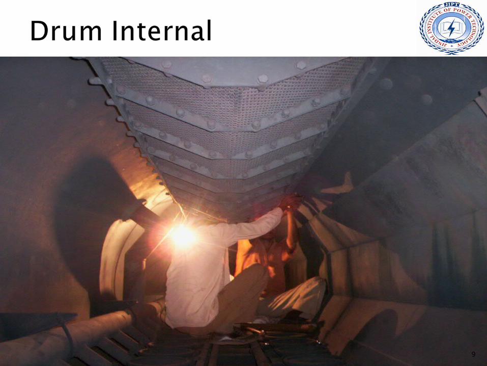
The fitting and alignment of drum internals are very important for its efficient performance. Any misalignment with gap will lead to heavy carry-over of impurities into steam which will get deposited in the super heater . The alignment should be checked and drum internals should be set right at every annual overhaul. In between also, it is desirable to check the drum internals fit up during any shut down for a few days.
29

THANK YOU
30