body electrical.pdf
TRANSCRIPT

BE0SD-04
I06143
6
3
I06144
6
3
I24666
Integration panel control assembly
-BODY ELECTRICAL ANTENNABE-175
2548Author: Date:
2004 LAND CRUISER (RM1071U)
INSPECTION1. Auto Antenna Models:
INSPECT ANTENNA MOTOR(a) Connect the positive (+) lead from the battery to terminal
3 and the negative (-) lead to terminal 6.(b) Check that the motor turns (moves upward).NOTICE:These tests must be done quickly (within 3 - 5 seconds) toprevent the coil from burning out.
(c) Then, reverse the polarity, check that the motor turns theopposite way (moves downward).
NOTICE:These tests must be done quickly (within 3 - 5 seconds) toprevent the coil from burning out.
2. INSPECT ANTENNA SWITCH CONTINUITY
Switch position Tester connection Specified condition
UP button FREE 4 - 5 No continuity
UP button Pushed in 4 - 5 Continuity
DOWN button FREE 9 - 5 No continuity
DOWN button Pushed in 9 - 5 Continuity
If continuity is not as specified, replace the switch.

I06145
Wire Harness Side
BE-176-BODY ELECTRICAL ANTENNA
2549Author: Date:
2004 LAND CRUISER (RM1071U)
3. Auto Antenna Models:INSPECT ANTENNA MOTOR CONTROL RELAY CIR-CUIT
Disconnect the connector from the relay and inspect the con-nector on wire harness side, as shown in the chart on the nextpage.
Tester connection Condition Specified condition
1 - Ground Antenna ”UP” switch OFF No continuity
1 - Ground Antenna ”UP” switch ON Continuity
5 - Ground Constant Continuity
9 - Ground Antenna ”DOWN” switch OFF No continuity
9 - Ground Antenna ”DOWN” switch ON Continuity
4 - Ground Constant Battery positive voltage
7 - Ground Ignition switch ACC or LOCK No voltage
7 - Ground Ignition switch ON Battery positive voltage
17 - Ground Ignition switch LOCK No voltage
17 - Ground Ignition switch ACC or ON Battery positive voltage
If circuit is as specified, replace the relay.

BE0G9-04
I09910
Antenna
Antenna Motor
View ”A”
View ”A” View ”B”
View ”C” View ”D”
Passenger AirbagSensor Assembly
Rainforcement
Piller
Rear Door Glass
Front Door Glass
View ”B”View ”C”
View ”D”
Radio Assembly: Clamp
Radio assembly
Front Door Glass
Quater WindowGlass
BE-174-BODY ELECTRICAL ANTENNA
2547Author: Date:
2004 LAND CRUISER (RM1071U)
ANTENNALOCATION

BE0N7-06
BE4671
Antenna Nut
BE5781
BE5780
BE4674
Twist
-BODY ELECTRICAL ANTENNABE-177
2550Author: Date:
2004 LAND CRUISER (RM1071U)
REPLACEMENT1. Auto antenna models:
REMOVE ANTENNA RODHINT:Do this operation with the battery negative (-) cable connectedto the battery terminal.(a) Remove the antenna nut.(b) Turn the radio switch ”ON” position.(c) Turn the antenna switch to ”UP”.
(d) Catch the antenna rod by hand and turn the radio switch”OFF”.
(e) Try again to turn the radio switch ”ON” and antenna switch”UP”.
(f) Remove antenna rod.HINT:The rod will extend fully and be released form the motor anten-na.NOTICE:To prevent body damage when the antenna rod is released,hold the rod while it comes out.
2. Auto antenna models:INSTALL ANTENNA ROD
(a) Insert the cable of the rod until it reaches the bottom.HINT: When inserting the cable, the teeth on the cable must face
toward the rear of the vehicle. Insert the antenna approx. 350 mm.
(b) Turn the radio switch to ”OFF”.HINT: In case the cable is not wound, twist it, as shown in the
illustration. Even if the rod has not retracted fully, install the antenna
nut and inspect the antenna rod operation. It will finally re-tract fully.
(c) Inspect the antenna rod operation by pushing the radiowave band select buttons.

BE2E8-01
30 kHz 300 kHz 3 MHz 30 MHz 300 MHz
LF MF HF VHF
AM FM
Frequency modulation
Frequency
Designation
Radio wave
Modulation Amplitude modulation
BE2818
FM (Stereo)
FM (Monaural)
AM
BE2819
Fading: lonosphere
BE-124-BODY ELECTRICAL AUDIO SYSTEM
2497Author: Date:
2004 LAND CRUISER (RM1071U)
AUDIO SYSTEMDESCRIPTION1. RADIO WAVE BAND
The radio wave bands used in radio broadcasting are as follows:
LF: Low FrequencyMF: Medium FrequencyHF: High FrequencyVHF: Very High Frequency
2. SERVICE AREAThere are great differences in the size of the service area for AMand FM monaural. Sometimes FM stereo broadcasts cannot bereceived even through AM can be received in very clearly.Not only does FM stereo have the smallest service area, but italso picks up static and other types of interference (”noise”)easily.
3. RECEPTION PROBLEMSBesides the problem of static, there are also the problemscalled ”fading”, ”multipath” and ”fade out”. These problems arecaused not by electrical noise but by the nature of the radiowaves themselves.
(1) FadingBesides electrical interference, AM broadcasts arealso susceptible to other types of interference, es-pecially at night. This is because AM radio wavesbounce off the ionosphere at night. These radiowaves then interfere with the signals from the sametransmitter that reach the vehicle’s antenna directly.This type of interference is called ”fading”.
BE2820
Multipath
BE2821
Fade Out
Noise occurs at a specific place. Strong possibility of foreign noise.
There is a possibility that the same program is broadcastedfrom different local stations, and that might be listening aprogram from other station.
Strong possibility of the beat from a distant broadcasting.
Strong possibility of multipath noise and fading noise causedby the changes of FM waves.
Noise occurs when listening to faintbroadcasting.
Noise occurs only at night.
Noise occurs while driving on a partic-ular area..FM
AM
HINT:In the condition of noise occurrence does not meet any of theabove questionnaire, check the problems to ”ReceptionProblem” on the previous page.
-BODY ELECTRICAL AUDIO SYSTEMBE-125
2498Author: Date:
2004 LAND CRUISER (RM1071U)
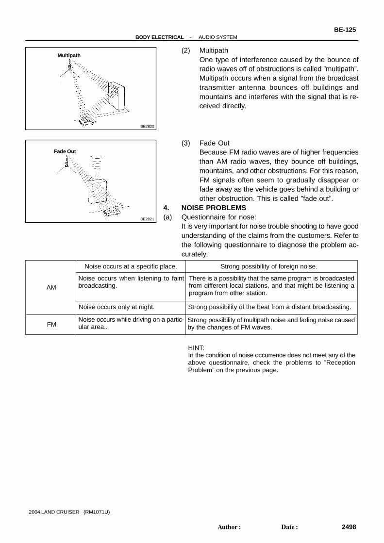
(2) MultipathOne type of interference caused by the bounce ofradio waves off of obstructions is called ”multipath”.Multipath occurs when a signal from the broadcasttransmitter antenna bounces off buildings andmountains and interferes with the signal that is re-ceived directly.
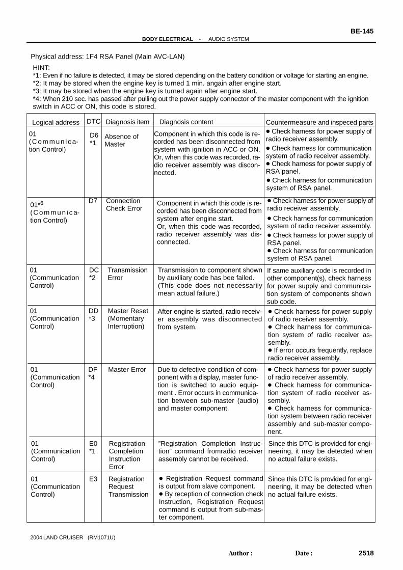
(3) Fade OutBecause FM radio waves are of higher frequenciesthan AM radio waves, they bounce off buildings,mountains, and other obstructions. For this reason,FM signals often seem to gradually disappear orfade away as the vehicle goes behind a building orother obstruction. This is called ”fade out”.
4. NOISE PROBLEMS(a) Questionnaire for nose:
It is very important for noise trouble shooting to have goodunderstanding of the claims from the customers. Refer tothe following questionnaire to diagnose the problem ac-curately.

N17398
Example:Head Capstan
Pinch Roller
BE-126-BODY ELECTRICAL AUDIO SYSTEM
2499Author: Date:
2004 LAND CRUISER (RM1071U)
(b) Matters that require attention when checking: Noise coming into the radio usually has no harm for
daily use as the noise protection is taken, and it isvery rate for an extremely loud noise to come in.When extremely loud noise comes into the radio,check if the grounding is normal where the antennais installed.
Check if all the regular noise prevention parts areproperly installed, and if there is any installation ofnon-authorized parts and non-authorized wiring.
If you leave the radio under out of tune (not turning),it is easy to diagnose the phenomenon as noise oc-curs frequently.
(c) Antenna and noise:Electronic signal received by the antenna will reach to theradio transmitting through the core wire of the coaxialcable. Any noise wave other than radio wave is mixed intothis core wire, that naturally causes noise in the radio andpoor sound quality. In order to prevent the noise fromcoming into radio, the core wire inside the coaxial cableis covered with a mesh wire called shield wire which trans-mits the noise to the ground.
5. COMPACT DISC PLAYERCompact Disc Players use a laser beam pick-up to read the dig-ital signals recorded on the CD and reproduce analog signalsof the music, etc.HINT:Never attempt to disassemble or oil any part of the player unit.Do not insert any object other than a disc into the magazine.NOTICE:CD players use an invisible laser beam which could causehazardous radiation exposure. Be sure to operate the play-er correctly as instructed.
6. Tape player/head cleaning:MAINTENANCE
(a) Raise the cassette door with your finger.Next, using a pencil or similar object, push in the guide.
(b) Using a cleaning pen or cotton applicator soaked in clean-er, clean the head surface, pinch rollers and capstans.

BE4331
I10058
Radio Receiver Assembly Power Amplifier DVD Auto Changer<Example>
-BODY ELECTRICAL AUDIO SYSTEMBE-127
2500Author: Date:
2004 LAND CRUISER (RM1071U)
7. CD player/disc cleaning:MAINTENANCE
If the disc gets dirty, clean the disc by wiping the surface fromthe center to outside in the radial directions with a soft cloth.NOTICE:Do not use a conventional record cleaner or anti-static pre-servative.
8. OUTLINE OF AVC-LAN(a) What is AVC-LAN?
AVC-LAN is the abbreviation, which stands for Audio Visual Communication-Local Area Network.This is a unified standard co-developed by 6 audio manufactures associated with Toyota Motor Corpo-ration.The Unified standard covers signals, such as audio signal, visual signal, signal for switch indicationand communication signal. Radio receiver assembly and RSA (Rear Seat Audio) panel have a resis-tance (60 - 80 Ω) required for communication.
(b) ObjectivesRecently the car audio system has been rapidly developed and functions have been changed drasti-cally. The conventional system has been switched to the multi-media type such as a navigation sys-tem. At the same time the level of customers needs to audio system has been upgraded. This lies be-hind this standardization.The concrete objectives are explained below.(1) When products by different manufactures were combined together, there used to be a case that
malfunction occurred such as sound did not come out. This problem has been resolved by stan-dardization of signals.
(2) Various types of after market products have been able to add or replace freely.(3) Because of the above (2), each manufacture has become able to concentrate on developing
products in their strongest field. This has enabled many types of products provided inexpensive-ly.
(4) In general, a new product developed by one particular manufacture could not be used due toa lack of compatibility with other manufactures products. Because of this new standard, userscan enjoy many compatible products from different manufacture anytime they went.
(c) The above descriptions are the objectives to introduce AVC-LAN. By this standardization, develop-ment of new products will no longer cause systematic errors.

I25240
AVC-LAN:
Main AVC-LAN
Power Amplifier (*) RSA PanelRadio Receiver Assembly DVD Auto Chager
*: Except JBL System
BE-128-BODY ELECTRICAL AUDIO SYSTEM
2501Author: Date:
2004 LAND CRUISER (RM1071U)
HINT: When +B short or GND short is detected in AVC-LAN circuit, communication stops. And audio system
does not function normally. When audio system is not equipped with a navigation system, audio head unit is the master unit. When
audio system is equipped with a navigation system, multi-display is the master unit. This system has 2 kinds of AVC-LAN, Main AVC-LAN and Sub AVC-LAN. RSA panel works as a master unit in the Sub AVC-LAN, but not in the Main AVC-LAN. The car audio system using AVC-LAN circuit has a diagnosis function.
(w/ Navigation system (see pageDI-1263 ) Each product has its own specified numbers called physical address. Numbers are also allotted to
each function in one product, which are called logical address.

I25541
1234567
8910111213141516
BE2EA-01
I25540
-BODY ELECTRICAL AUDIO SYSTEMBE-171
2544Author: Date:
2004 LAND CRUISER (RM1071U)
INSPECTION1. INSPECT POWER AMPLIFIER CIRCUITDisconnect the connector from power amplifier and inspect theconnector on the wire harness side.
Tester connection Condition Specified condition
12 - Ground Constant Continuity
13 - Ground Constant Continuity
7 - Ground Constant Battery voltage
16 - Ground Constant Battery voltage
If the circuit is not as specified, inspect the circuits connectedto other parts.
2. INSPECT REAR SEAT AUDIO CIRCUITDisconnect the connector from RSA controller and inspect theconnector on the wire harness side.
Tester connection Condition Specified condition
17 - Ground Constant Continuity
24 - Ground Ignition switch LOCK and radio switch ON No voltage
24 - Ground Ignition switch ACC or ON and radio switch ON Battery voltage
12 - Ground Constant Battery voltage
If the circuit is not as specified, inspect the circuits connectedto other parts.

I25542
I25539
Connector ”A”
Connector ”B”
Connector ”C”
BE-172-BODY ELECTRICAL AUDIO SYSTEM
2545Author: Date:
2004 LAND CRUISER (RM1071U)
3. INSPECT DVD CHANGER CIRCUITDisconnect the connector from DVD changer and inspect theconnector on the wire harness side.
Tester connection Condition Specified condition
20 - Ground Constant Continuity
1 - Ground Ignition switch LOCK No voltage
1 - Ground Ignition switch ACC or ON Battery voltage
10 - Ground Constant Battery voltage
If the circuit is not as specified, inspect the circuits connectedto other parts.
4. INSPECT RADIO RECEIVER ASSEMBLY CIRCUITDisconnect the connectors from the radio receiver assembly,and inspect the connector on the wire harness side.
Tester connection Condition Specified condition
A20 - Ground Constant Continuity
A1 - Ground Constant Battery voltage
A11 - Ground Ignition switch LOCK No voltage
A11 - Ground Ignition switch ACC or ON Battery voltage
If the circuit is not as specified, inspect the circuits connectedto other parts.

I24857EAU AU1AU2
-BODY ELECTRICAL AUDIO SYSTEMBE-173
2546Author: Date:
2004 LAND CRUISER (RM1071U)
HINT:Check the wire harness between radio receiver assembly andthe CD auto changer, between radio receiver assembly andpower amplifier.
5. INSPECT STEERING PAD SWITCH CIRCUITDisconnect the connectors from the steering pad switch, and in-spect the connector on the wire harness side.
Tester connection Condition Specified condition
AU1 - EAU Do not switch position Approx. 100 kΩ
AU1 - EAU SEEK+ switch: push 0 Ω
AU1 - EAU SEEK- switch: push Approx. 0.3 Ω
AU1 - EAU VOL+ switch: push Approx. 1k Ω
AU1 - EAU VOL- switch: push Approx. 3.2 kΩ
AU2 - EAU Do not switch position Approx. 100 kΩ
AU2 - EAU MODE switch: push 0 Ω
If the circuit is not as specified, inspect the circuits connectedto other parts.

BE0GD-23
I25523
Cowl SIde J/B RH RADIO Fuse
Tweeter
Radio Assembly
Ignition Switch
Engine Room R/B AMP Fuse
Woofer
Speakers
SpeakersPower Amplifier
Steering Pad Switch
RSA
Antenna Assembly Motor Antenna
Cowl Side J/B LH ECU IG1 Fuse IG Fuse
BE-170-BODY ELECTRICAL AUDIO SYSTEM
2543Author: Date:
2004 LAND CRUISER (RM1071U)
LOCATION

BE2E9-01
I25054
”TUNE DOWN” Switch
”4ch” Switch
”5ch” Switch”6ch” Switch
”TUNE UP” Switch
”1ch” Switch”2ch” Switch
”3ch” Switch
”DISC” Switch
-BODY ELECTRICAL AUDIO SYSTEMBE-129
2502Author: Date:
2004 LAND CRUISER (RM1071U)
TROUBLESHOOTING1. DIAGNOSIS FUNCTION (Main AVC-LAN)(a) Diagnosis start-up
For shifting to diagnosis mode, turn the ignition switch ON and push the ”DISC” switch 3 times whilepressing ”ch1” and ”ch6” switches.
HINT:To exit the diagnosis mode, push the ”DISC” switch for 1.7 sec. or turn the ignition switch to ACC or OFF.(b) Element check mode
After the diagnosis start-up, the system enters the element check mode. Check that the all elementslight up.
HINT:By pressing the ”TUNE UP” switch, the system enters the ”Service Check Mode”.(c) Switch check mode
(1) Element check mode is started at the same time with the switch check mode.(2) Check that there is a beep sound when any switch is pressed.
HINT:By pressing ”TUNE UP” switch, the system enters the ”Service Check Mode”.

I25054
”TUNE DOWN” Switch
”4ch” Switch
”5ch” Switch”6ch” Switch
”TUNE UP” Switch
”1ch” Switch”2ch” Switch
”3ch” Switch
”DISC” Switch
BE-130-BODY ELECTRICAL AUDIO SYSTEM
2503Author: Date:
2004 LAND CRUISER (RM1071U)
(d) Service check mode(1) After the element check and switch check is completed, the system enters service check mode
when ”TUNE UP” switch is pressed.(2) Error codes over the tuner and connected equipments are displayed on the screen of the tuner.
Results for each check are displayed as follows: good:
No DTC is detected for both ”System Check Confirmation” and ”Diagnosis Memory Re-sponse”.
nCon: The component does not respond to the ”Diagnosis On Instruction” command.Applicable to only the system where connected components are limited to be used.
ECHn: Application of new version has been confirmed by the ”Diagnosis On Check”, and thereis one or more DTC which indicates ”Replacement” in the ”System Check Result Re-sponse” or ”Diagnosis Memory Response”.
CHEC: Application of new version has been confirmed by the ”Diagnosis On Check”, and thereis no DTC which indicates ”Replacement” in the ”System Check Result Response” or”Diagnosis Memory Response”, but one or more DTC which indicates ”Check” is identified.
Old:Application of old version is confirmed by the ”Diagnosis On Check”, and DTC is identifiedin the ”System Check Result Response” or ”Diagnosis Memory Response”.
nrES:No response is identified to the ”System Check Start Instruction” and ”Request for SystemCheck Result” commands.
HINT: Check the present and past condition of components by performing the System Check and collecting
stored DTC memories. Check results are displayed as one of the following six indications: ”good”, ”ECHn”, ”CHEC”,”nCon”,
”Old” or ”nrES”.

Normal Mode
Service Check ModePhysical Address (When checking, P1F4 is blinking)
A long beep (3 sec.)
3 beeps
Memory Clear Mode
After 3 sec.
P1F4
ECHn
CLr
Example:Connection parts ( physical address): Radio receiver (P190), RSA ECU (P1F4), DVD player (P1A0)
Turn ignition switch ON.Push the ”DISC” switch 3 timeswhile pressing ”ch1” and ”ch6”switches.
HINT:To exit diagnosis mode, pressthe ”DISC” switch for 1.7 sec. orturn ignition switch to ACC orOFF
”ECHn” Detail Display Mode (Refer to (f))
CHEC”CHEC” Detail Display Mode (Refer to (g))
Physical AddressP190
Physical AddressP1A0
Old”Old” Detail Display Mode (Refer to (h))
Result (Replacing)
Result (Check)
Result (Old)
After the memory is cleared, only the physical address is displayed cyclically.
TUNE UP
TUNE UP
TUNE UP
TUNE UP
TUNE DOWN
TUNE DOWN
TUNE DOWN
TUNE DOWN
TUNE DOWN
TUNE UP
ch5 (1.7 sec.): Indicates a switch operation
ch2
ch3
ch2
ch3
ch2
ch3
When re-checking (ch1 switch is pressed) in that condition, the result is alsodisplayed as shown above.
Element check modeSwitch Check Mode
TUNE UP
-BODY ELECTRICAL AUDIO SYSTEMBE-131
2504Author: Date:
2004 LAND CRUISER (RM1071U)
(e) Display Screen for Service Check.

Service Check Mode
”ECHn” Detail Display Mode
Physical Address of Component
Logical Address
Number of Occurrence (*2)
DTC (Refer to diagnostic trouble code chart)
Logical Address
Connection Check Code (*2)
Continued if more than one DTC is identified.
Details for 1st Component
Details for 2nd Component
ECHn
P1F4
ch2ch3
TUNE UPTUNE DOWN
P1F4
SyS
COdE
DTC (Refer to diagnostic trouble code chart)
Auxiliary Code (*1)
ch5 (Along)
CLr
: Indicates a switch operation
TUNE UP
TUNE UP
TUNE UP
TUNE UP
TUNE UP
TUNE UP
TUNE DOWN
TUNE DOWN
TUNE DOWN
TUNE DOWN
TUNE DOWN
TUNE DOWN
TUNE DOWN
TUNE DOWN
TUNE DOWN
TUNE DOWN
TUNE DOWN
TUNE UPTUNE DOWN
TUNE UP
Detail code is displayed cyclically.
TUNE UP
TUNE UP
TUNE UP
TUNE UP
(*1): Some diagnostic codes may not be displayed. In this case, ”- - -” displayed.
(*2): Some diagnostic codes may not be displayed. In this case, ”- -” displayed.
1L **
1d 21
2L **
2d D7
2P ***
2n **
2c **
BE-132-BODY ELECTRICAL AUDIO SYSTEM
2505Author: Date:
2004 LAND CRUISER (RM1071U)
(f) ”ECHn” Detail Display Mode Screen

Service Check Mode
”CHEC” Detail Display ModePhysical Address of Component
Logical Address
Number of Occurrence (*2)
DTC (Refer to diagnostic trouble code chart)
Continued if more than one DTC is identified.
Details for 1st Component
Details for 2nd Component
CHEC
P190
ch2ch3
TUNE UPTUNE DOWN
P190
COde
DTC (Refer to diagnostic trouble code chart)
ch5 (Along)
CLr
: Indicates a switch operation
Auxiliary Code (*1)
Connection Check Code (*2)
Logical Address
Connection Check Code (*2)
TUNE UP
TUNE DOWN
Detail code is displayed cyclically.
Auxiliary Code (*1)
Number of Occurrence (*2)
TUNE UP
TUNE UP
TUNE UP
TUNE UP
TUNE UP
TUNE UP
TUNE UP
TUNE UP
TUNE UP
TUNE UP
TUNE UP
TUNE DOWN
TUNE DOWN
TUNE DOWN
TUNE DOWN
TUNE DOWN
TUNE DOWN
TUNE DOWN
TUNE DOWN
TUNE DOWN
TUNE DOWN
TUNE DOWN
TUNE DOWN
TUNE UPTUNE DOWN
TUNE UP
1L **
1d E4
2L **
2d 43
2P ***
2n **
1P ***
1n **
2c **
1c **
(*1): Some diagnostic codes may not be displayed. In this case, ”- - -” displayed.
(*2): Some diagnostic codes may not be displayed. In this case, ”- -” displayed.
-BODY ELECTRICAL AUDIO SYSTEMBE-133
2506Author: Date:
2004 LAND CRUISER (RM1071U)
(g) ”CHEC” Detail Display Mode Screen

Service Check Mode
”Old” Detail Display ModePhysical Address of Component
Logical Address
Number of Occurrence (*2)
DTC (Refer to diagnostic trouble code chart)
Continued if more than one DTC is identified.
Details for 1st Component
Details for 2nd Component
Old
P1A0
ch2ch3
TUNE UPTUNE DOWN
P1A0
COdE
DTC (Refer to diagnostic trouble code chart)
ch5 (Along)
CLr
: Indicates a switch operation
Auxiliary Code (*1)
Connection Check Code (*2)
Logical Address
Connection Check Code (*2)
TUNE UP
TUNE DOWN
Detail code is displayed cyclically.
Auxiliary Code (*1)
Number of Occurrence (*2)
TUNE UP
TUNE UP
TUNE UP
TUNE UP
TUNE UP
TUNE UP
TUNE UP
TUNE UP
TUNE UP
TUNE UP
TUNE UP
TUNE DOWN
TUNE DOWN
TUNE DOWN
TUNE DOWN
TUNE DOWN
TUNE DOWN
TUNE DOWN
TUNE DOWN
TUNE DOWN
TUNE DOWN
TUNE DOWN
TUNE DOWN
TUNE UPTUNE DOWN
TUNE UP
1L **
1d d4
2L **
2d 43
2P ***
2n **
1P ***
1n **
2c
1c - -
- -
(*1): Some diagnostic codes may not be displayed. In this case, ”- - -” displayed.
(*2): Some diagnostic codes may not be displayed. In this case, ”- -” displayed.
BE-134-BODY ELECTRICAL AUDIO SYSTEM
2507Author: Date:
2004 LAND CRUISER (RM1071U)
(h) ”Old” Detail Display Mode Screen

I25241
”TUNE DOWN” Switch ”TUNE UP” Switch
-BODY ELECTRICAL AUDIO SYSTEMBE-135
2508Author: Date:
2004 LAND CRUISER (RM1071U)
2. DIAGNOSIS FUNCTION (Sub AVC-LAN)HINT:As starting Main AVC-LAN to operate the diagnosis mode, Sub AVC-LAN is automatically to the mode. Per-form the diagnosis mode operation on the RSA panel.(a) Element check mode
After the diagnosis start-up, the system enters the element check mode. Check that the all elementslight up.
HINT:By pressing the ”TUNE UP” switch, the system enters the ”Service Check Mode”.(b) Switch check mode
(1) Element check mode is started at the same time with the switch check mode.(2) Check that there is a beep sound when any switch is pressed.
HINT:By pressing ”TUNE UP” switch, the system enters the ”Service Check Mode”.

I25241
”TUNE DOWN” Switch ”TUNE UP” Switch
BE-136-BODY ELECTRICAL AUDIO SYSTEM
2509Author: Date:
2004 LAND CRUISER (RM1071U)
(c) Service check mode(1) After the element check and switch check is completed, the system enters service check mode
when ”TUNE UP” switch is pressed.(2) Error codes over the tuner and connected equipments are displayed on the screen of the tuner.
Results for each check are displayed as follows: good:
No DTC is detected for both ”System Check Confirmation” and ”Diagnosis Memory Re-sponse”.
nCon: The component does not respond to the ”Diagnosis On Instruction” command.Applicable to only the system where connected components are limited to be used.
ECHn: Application of new version has been confirmed by the ”Diagnosis On Check”, and thereis one or more DTC which indicates ”Replacement” in the ”System Check Result Re-sponse” or ”Diagnosis Memory Response”.
CHEC: Application of new version has been confirmed by the ”Diagnosis On Check”, and thereis no DTC which indicates ”Replacement” in the ”System Check Result Response” or”Diagnosis Memory Response”, but one or more DTC which indicates ”Check” is identified.
Old:Application of old version is confirmed by the ”Diagnosis On Check”, and DTC is identifiedin the ”System Check Result Response” or ”Diagnosis Memory Response”.
nrES:No response is identified to the ”System Check Start Instruction” and ”Request for SystemCheck Result” commands.
HINT: Check the present and past condition of components by performing the System Check and collecting
stored DTC memories. Check results are displayed as one of the following six indications: ”good”, ”ECHn”, ”CHEC”,”nCon”,
”Old” or ”nrES”.

Normal Mode
Service Check ModePhysical Address (When checking, P1F4 is blinking)
A long beep (3 sec.)
3 beeps
Memory Clear Mode
After 3 sec.
P1F4
ECHn
CLr
Example:Connection parts ( physical address): Radio receiver (P190), RSA ECU (P1F4), DVD player (P1A0)
Diagnosis of main AVC- LANstart up.
HINT:To exit diagnosis mode, pressthe ”DISC” switch for 1.7 sec. orturn ignition switch to ACC orOFF
”ECHn” Detail Display Mode (Refer to (e))
CHEC”CHEC” Detail Display Mode (Refer to (f))
Physical AddressP190
Physical AddressP1A0
Old”Old” Detail Display Mode (Refer to (g))
Result (Replacing)
Result (Check)
Result (Old)
After the memory is cleared, only the physical address is displayed cyclically.
OFF (1.7 sec.): Indicates a switch operation
When re-checking (ch1 switch is pressed) in that condition, the result is alsodisplayed as shown above.
Element check modeSwitch Check Mode
V
TUNE/TRACK
V
TUNE/TRACK
V
TUNE/TRACK
VTUNE/TRACK
V
TUNE/TRACK
V
TUNE/TRACK
VTUNE/TRACK
VTUNE/TRACK
VTUNE/TRACK
VTUNE/TRACK
VTUNE/TRACK V
DISC/CH/PROG
VDISC/CH/PROG
V
DISC/CH/PROG
VDISC/CH/PROG
V
DISC/CH/PROG
VDISC/CH/PROG
-BODY ELECTRICAL AUDIO SYSTEMBE-137
2510Author: Date:
2004 LAND CRUISER (RM1071U)
(d) Display Screen for Service Check.

Service Check Mode
”ECHn” Detail Display Mode
Physical Address of Component
Logical Address
Number of Occurrence (*2)
DTC (Refer to diagnostic trouble code chart)
Logical Address
Connection Check Code (*2)
Continued if more than one DTC is identified.
Details for 1st Component
Details for 2nd Component
ECHn
P1F4
P1F4
SyS
COdE
DTC (Refer to diagnostic trouble code chart)
Auxiliary Code (*1)
OFF (Along)
CLr
: Indicates a switch operation
Detail code is displayed cyclically.
(*1): Some diagnostic codes may not be displayed. In this case, ”- - -” displayed.
(*2): Some diagnostic codes may not be displayed. In this case, ”- -” displayed.
1L **
1d 21
2L **
2d D7
2P ***
2n **
2c **
V
TUNE/TRACK VTUNE/TRACK
V
DISC/CH/PROG VDISC/CH/PROG
V
TUNE/TRACK
V
TUNE/TRACK
V
TUNE/TRACK V
TUNE/TRACK
V
TUNE/TRACK
V
TUNE/TRACK
V
TUNE/TRACK
V
TUNE/TRACK
V
TUNE/TRACK
V
TUNE/TRACK
VTUNE/TRACK
VTUNE/TRACK
VTUNE/TRACK
VTUNE/TRACK
VTUNE/TRACK
VTUNE/TRACK
VTUNE/TRACK
VTUNE/TRACK
VTUNE/TRACK
VTUNE/TRACK V
TUNE/TRACK
VTUNE/TRACK
V
TUNE/TRACK VTUNE/TRACK
BE-138-BODY ELECTRICAL AUDIO SYSTEM
2511Author: Date:
2004 LAND CRUISER (RM1071U)
(e) ”ECHn” Detail Display Mode Screen

Service Check Mode
”CHEC” Detail Display ModePhysical Address of Component
Logical Address
Number of Occurrence (*2)
DTC (Refer to diagnostic trouble code chart)
Continued if more than one DTC is identified.
Details for 1st Component
Details for 2nd Component
CHEC
P190
P190
COde
DTC (Refer to diagnostic trouble code chart)
CLr
: Indicates a switch operation
Auxiliary Code (*1)
Connection Check Code (*2)
Logical Address
Connection Check Code (*2)
Detail code is displayed cyclically.
Auxiliary Code (*1)
Number of Occurrence (*2)
1L **
1d E4
2L **
2d 43
2P ***
2n **
1P ***
1n **
2c **
1c **
(*1): Some diagnostic codes may not be displayed. In this case, ”- - -” displayed.
(*2): Some diagnostic codes may not be displayed. In this case, ”- -” displayed.
V
TUNE/TRACK
VTUNE/TRACK
V
DISC/CH/PROG VDISC/CH/PROG
V
TUNE/TRACK
V
TUNE/TRACK
V
TUNE/TRACK
V
TUNE/TRACK
V
TUNE/TRACK
V
TUNE/TRACK
V
TUNE/TRACK
V
TUNE/TRACK
V
TUNE/TRACK
VTUNE/TRACK
VTUNE/TRACK
VTUNE/TRACK
VTUNE/TRACK
VTUNE/TRACK
VTUNE/TRACK
VTUNE/TRACK
VTUNE/TRACK
VTUNE/TRACK
V
TUNE/TRACK
VTUNE/TRACK
V
TUNE/TRACK VTUNE/TRACK
V
TUNE/TRACK
V
TUNE/TRACK
VTUNE/TRACK
VTUNE/TRACK
VTUNE/TRACK
V
TUNE/TRACK
OFF (Along)
-BODY ELECTRICAL AUDIO SYSTEMBE-139
2512Author: Date:
2004 LAND CRUISER (RM1071U)
(f) ”CHEC” Detail Display Mode Screen

Service Check Mode
”Old” Detail Display ModePhysical Address of Component
Logical Address
Number of Occurrence (*2)
DTC (Refer to diagnostic trouble code chart)
Continued if more than one DTC is identified.
Details for 1st Component
Details for 2nd Component
Old
P1A0
P1A0
COdE
DTC (Refer to diagnostic trouble code chart)
CLr
: Indicates a switch operation
Auxiliary Code (*1)
Connection Check Code (*2)
Logical Address
Connection Check Code (*2)
Detail code is displayed cyclically.
Auxiliary Code (*1)
Number of Occurrence (*2)
1L **
1d d4
2L **
2d 43
2P ***
2n **
1P ***
1n **
2c
1c - -
- -
(*1): Some diagnostic codes may not be displayed. In this case, ”- - -” displayed.
(*2): Some diagnostic codes may not be displayed. In this case, ”- -” displayed.
VTUNE/TRACK
VTUNE/TRACK
VTUNE/TRACK
VTUNE/TRACK
VTUNE/TRACK
VTUNE/TRACK
VTUNE/TRACK
VTUNE/TRACK
VTUNE/TRACK
VTUNE/TRACK
VTUNE/TRACK
V
TUNE/TRACK
V
TUNE/TRACK
V
TUNE/TRACK
V
TUNE/TRACK
V
TUNE/TRACK
V
TUNE/TRACK
V
TUNE/TRACK
V
TUNE/TRACK
V
TUNE/TRACK
V
TUNE/TRACK
V
TUNE/TRACK
V
TUNE/TRACK
VTUNE/TRACK
OFF (Along) V
DISC/CH/PROG VDISC/CH/PROG
V
TUNE/TRACK
VTUNE/TRACK
V
TUNE/TRACK VTUNE/TRACK
VTUNE/TRACK
V
TUNE/TRACK
BE-140-BODY ELECTRICAL AUDIO SYSTEM
2513Author: Date:
2004 LAND CRUISER (RM1071U)
(g) ”Old” Detail Display Mode Screen

Physical address: 190 Radio receiver assembly
Diagnosis item
ROM Error
Absence of Master
Diagnosis content Countermeasure andinspected parts
Error is detected in internal ROM.
Logical address
01(CommunicationControl)
01 *2(CommunicationControl)
Component in which this code is re-corded has been disconnected fromsystem with ignition in ACC or ON.Or, when this code was recorded, ra-dio receiver assembly was discon-nected.
Check harness for power supplysystem of radio receiver assembly. Check harness for communica-tion system of radio receiver as-sembly.
DTC
21
D6
Replace radio receiver assembly.
RAM Error Error is detected in internal RAM.01(CommunicationControl)
22 Replace radio receiver assembly.
No Response to Connection Check
01 *3(CommunicationControl)
Component shown by auxiliary codeis or had been disconnected fromsystem after engine start. D9
Check harness for power supplysystem of component shown byauxiliary code. Check harness for communica-tion system of component shown byauxiliary code.
D8
Last Mode Error01 *2(CommunicationControl)
Component operated (sounds and/or images were provided) before en-gine stop is or has been discon-nected with ignition switch in ACC orON.
Check harness for power supplysystem of component shown byauxiliary code. Check harness for communica-tion system of component shown byauxiliary code.
D9
No Response to ON/OFF Instruction
No response is identified whenchanging mode (audio and visualmode change). Detected whensound and picture does not changeby button operation.
DA01(CommunicationControl)
Check harness for power supplyof component shown by auxiliarycode. Check harness for communica-tion system of component shown byauxiliary code. If error occurs again, replacecomponent shown by auxiliarycode.
HINT:*1: Even if no failure is detected, it may be stored depending on the battery condition or voltage for starting an engine.*2: It may be stored when the engine key is turned 1 min. angain after engine start.*3: It may be stored when the engine key is turned again after engine start.*4: When 210 sec. has passed after pulling out the power supply connector of the master component with the ignitionswitch in ACC or ON, this code is stored.
Mode StatusError
DB01 *2(CommunicationControl)
Dual alarm is detected. Check harness for power supplyof component shown by auxiliarycode. Check harness for communica-tion system of component shown byauxiliary code.
-BODY ELECTRICAL AUDIO SYSTEMBE-141
2514Author: Date:
2004 LAND CRUISER (RM1071U)
3. DIAGNOSIS CODE LISTw/ Navigation system (See page)

TransmissionError
DC01 *4(CommunicationControl)
Transmission to component shownby auxiliary code has been failed.(Detecting this DTC does not nec-essary mean actual failure.)
If same auxiliary code is recordedin other component, check harnessfor power supply and communica-tion system of components shownsub code.
Master Reset(Momentary Interruption)
DD01 *3(CommunicationControl)
After engine is started, radio receiv-er assembly assembly was discon-nected from system.
If this error occurs frequently, re-place radio receiver assembly.
Slave Reset(MomentaryInterruption)
DE01 *3(CommunicationControl)
After engine is started, slave com-ponent was disconnected from sys-tem.
Check harness for power supplyof component shown by auxiliarycode. Check harness for communica-tion system of component shown byauxiliary code.
Master ErrorDF01 *4(CommunicationControl)
Due to defective condition of radioreceiver assembly, master functionis switched to audio equipment.Error occurs in communication be-tween sub-master (audio) and ra-dio receiver assembly.
Check harness for power supplyof radio receiver assembly. Check harness for communica-tion system of radio receiver as-sembly . Check harness for communica-tion system between radio receiverassembly and sub-master compo-nent.
RegistrationCompletionInstructionError
E001(CommunicationControl)
”Registration Completion Instruc-tion” command from radio receiverassembly cannot be received.
Since this DTC is provided for en-gineering purpose, it may be de-tected when no actual failure exists.
Audio processor ON error
E101 *2(CommunicationControl)
While source equipment is operat-ing, AMP output is stopped.
Check harness for power supplyof radio receiver assembly. Check harness for communica-tion system of radio receiver as-sembly.
ON/OFFInstructionParameterError
E201(CommunicationControl)
Error occurs in ON/OFF controllingcommand from radio receiver as-sembly assembly.
Replace radio receiver assembly.
RegistrationRequestTransmission
E301(CommunicationControl)
Registration Request command isoutput from slave component.Receiving Connection CheckInstruction, Registration Requestcommand is output from sub-mas-ter component.
Since this DTC is provided for en-gineering purpose, it may be de-tected when no actual failure exists.
Plural FrameAbort
E401(CommunicationControl)
Since this DTC is provided for en-gineering purpose, it may be de-tected when no actual failure exists.
Plural frame transmission isaborted.
AM Tuner Error4360(Radio receiverassembly)
Replace radio receiver assembly.Abnormal condition is detected inAM tuner. Inspect radio receiver assembly.
FM Tuner Error4460(Radio receiverassembly)
Replace radio receiver assembly.Abnormal condition is detected inFM tuner.
BE-142-BODY ELECTRICAL AUDIO SYSTEM
2515Author: Date:
2004 LAND CRUISER (RM1071U)

EJECT Malfunction
4161(Cassette switch)
Malfunction due to mechanical fail-ure.
Replace radio receiver assembly.
63 (In-dash CDauto changer)
42 No Disc Readout
Disc cannot be read. Inspect CD.
63 (In-dash CDauto changer)
44 CD Error Error is detected in CD auto changer.
Replace radio receiver assembly.
Physical address: 440 Strereo component amplifier
01 (C o m m u n i c a-tion Control)
22 RAM Error
01(C o m m u n i c a-tion Control)
D6*1
Absence of Master
Component in which this code is re-corded has been disconnected fromsystem with ignition in ACC or ON.Or, when this code was recorded, ra-dio receiver assembly was discon-nected.
Check harness for power supply ofradio receiver assembly. Check harness for communicationsystem of radio receiver assembly. Check harness for power supply ofstereo component amplifier. Check harness for communicationsystem of stereo component ampli-fier.
HINT:*1: Even if no failure is detected, it may be stored depending on the battery condition or voltage for starting an engine.*2: It may be stored when the engine key is turned 1 min. angain after engine start.*3: It may be stored when the engine key is turned again after engine start.*4: When 210 sec. has passed after pulling out the power supply connector of the master component with the ignitionswitch in ACC or ON, this code is stored.
Logical address DTC Diagnosis item Diagnosis content Countermeasure and inspeced parts
01 (C o m m u n i c a-tion Control)
21 ROM Error Abnormal condition of ROM is detected.
Replace stereo component amplifier.
Abnormal condition of RAM is detected.
Replace stereo component amplifier.
63(In-dash CD auto Changer)
45 EJECT Error CD cannot be ejected. Replace radio receiver assembly.
63(In-dash CD auto Changer)
47 CD High Temp. High temperature is detected inCD auto changer.
Replace radio receiver assembly.
63(In-dash CD auto Changer)
48 CD Excess Current
Excess current is applied to CDauto changer.
Replace radio receiver assembly.
Mechanical or Media Error
4061(Cassette switch)
Inspect cassette tape.Malfunction due to mechanical fail-ure is identified. Or, cassette tape iscut or entangled.
-BODY ELECTRICAL AUDIO SYSTEMBE-143
2516Author: Date:
2004 LAND CRUISER (RM1071U)

01*6 (C o m m u n i c a-tion Control)
D7 Connection Check Error
Component in which this code is re-corded has been disconnected fromsystem after engine start.Or, when this code was recorded,radio receiver assembly was dis-connected.
Check harness for power supply ofradio receiver assembly.
Check harness for communicationsystem of radio receiver assembly. Check harness for power supply ofstereo component amplifier.
Check harness for communicationsystem of stereo component ampli-fier.
Transmission Error
DC*2
01(CommunicationControl)
Transmission to component shownby auxiliary code has bee failed. (This code does not necessarilymean actual failure.)
If same auxiliary code is recorded inother component(s), check harnessfor power supply and communica-tion system of components shownsub code.
Master Reset (Momentary Interruption)
DD*3
01 (CommunicationControl)
Check harness for power supplyof radio receiver assembly. Check harness for communica-tion system of radio receiver as-sembly. If error occurs frequently, replaceradio receiver assembly.
Registration Completion InstructionError
E0*1
01(CommunicationControl)
”Registration Completion Instruc-tion” command fromradio receiverassembly cannot be received.
Since this DTC is provided for engi-neering, it may be detected whenno actual failure exists.
ON/OFF InstructionParameter Error
E201(CommunicationControl)
Error is detected in ON/OFF controlcommand from radio receiver as-sembly.
Replace radio receiver assembly.
Registration Request Transmission
E301(CommunicationControl)
Since this DTC is provided for engi-neering, it may be detected whenno actual failure exists.
Registration Request commandis output from slave component. By reception of connection checkInstruction, Registration Requestcommand is output from sub-mas-ter component.
After engine is started, radio receiv-er assembly assembly was discon-nected from system.
Master ErrorDF*4
01(CommunicationControl)
Due to defective condition of com-ponent with a display, master func-tion is switched to audio equip-ment . Error occurs in communica-tion between sub-master (audio)and master component.
Check harness for power supplyof radio receiver assembly. Check harness for communica-tion system of radio receiver as-sembly. Check harness for communica-tion system between radio receiverassembly and sub-master compo-nent.
Audio proces-sor ON error
E1*1
01(CommunicationControl)
While source equipment is operat-ing, AMP output is stopped.
Check harness for power supply ofradio receiver assembly Check harness for communicationsystem of radio receiver assembly.
Plural Frame Abort
E401(CommunicationControl)
Plural frame transmission is aborted.
Since this DTC is provided for engi-neering purpose, it may be detectedwhen no actual failure exists.
BE-144-BODY ELECTRICAL AUDIO SYSTEM
2517Author: Date:
2004 LAND CRUISER (RM1071U)
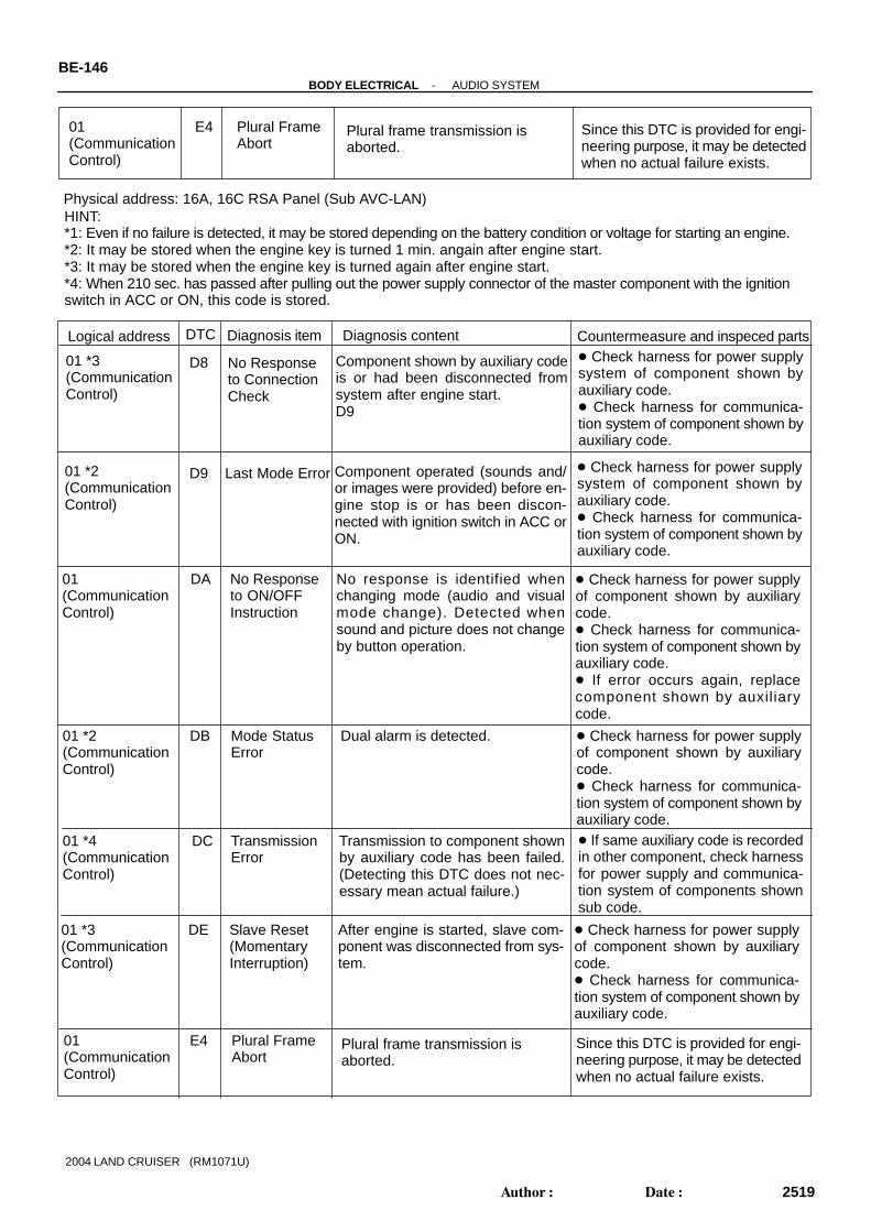
Physical address: 1F4 RSA Panel (Main AVC-LAN)
01(C o m m u n i c a-tion Control)
D6*1
Absence of Master
Component in which this code is re-corded has been disconnected fromsystem with ignition in ACC or ON.Or, when this code was recorded, ra-dio receiver assembly was discon-nected.
Check harness for power supply ofradio receiver assembly. Check harness for communicationsystem of radio receiver assembly. Check harness for power supply ofRSA panel. Check harness for communicationsystem of RSA panel.
HINT:*1: Even if no failure is detected, it may be stored depending on the battery condition or voltage for starting an engine.*2: It may be stored when the engine key is turned 1 min. angain after engine start.*3: It may be stored when the engine key is turned again after engine start.*4: When 210 sec. has passed after pulling out the power supply connector of the master component with the ignitionswitch in ACC or ON, this code is stored.
Logical address DTC Diagnosis item Diagnosis content Countermeasure and inspeced parts
Transmission Error
DC*2
01(CommunicationControl)
Transmission to component shownby auxiliary code has bee failed. (This code does not necessarilymean actual failure.)
If same auxiliary code is recorded inother component(s), check harnessfor power supply and communica-tion system of components shownsub code.
Master Reset (Momentary Interruption)
DD*3
01 (CommunicationControl)
Check harness for power supplyof radio receiver assembly. Check harness for communica-tion system of radio receiver as-sembly. If error occurs frequently, replaceradio receiver assembly.
Registration Completion InstructionError
E0*1
01(CommunicationControl)
”Registration Completion Instruc-tion” command fromradio receiverassembly cannot be received.
Since this DTC is provided for engi-neering, it may be detected whenno actual failure exists.
Registration Request Transmission
E301(CommunicationControl)
Since this DTC is provided for engi-neering, it may be detected whenno actual failure exists.
Registration Request commandis output from slave component. By reception of connection checkInstruction, Registration Requestcommand is output from sub-mas-ter component.
After engine is started, radio receiv-er assembly was disconnectedfrom system.
Master ErrorDF*4
01(CommunicationControl)
Due to defective condition of com-ponent with a display, master func-tion is switched to audio equip-ment . Error occurs in communica-tion between sub-master (audio)and master component.
Check harness for power supplyof radio receiver assembly. Check harness for communica-tion system of radio receiver as-sembly. Check harness for communica-tion system between radio receiverassembly and sub-master compo-nent.
01*6 (C o m m u n i c a-tion Control)
D7 Connection Check Error
Component in which this code is re-corded has been disconnected fromsystem after engine start.Or, when this code was recorded,radio receiver assembly was dis-connected.
Check harness for power supply ofradio receiver assembly.
Check harness for communicationsystem of radio receiver assembly. Check harness for power supply ofRSA panel. Check harness for communicationsystem of RSA panel.
-BODY ELECTRICAL AUDIO SYSTEMBE-145
2518Author: Date:
2004 LAND CRUISER (RM1071U)
No Response to Connection Check
01 *3(CommunicationControl)
Component shown by auxiliary codeis or had been disconnected fromsystem after engine start. D9
Check harness for power supplysystem of component shown byauxiliary code. Check harness for communica-tion system of component shown byauxiliary code.
D8
Last Mode Error01 *2(CommunicationControl)
Component operated (sounds and/or images were provided) before en-gine stop is or has been discon-nected with ignition switch in ACC orON.
Check harness for power supplysystem of component shown byauxiliary code. Check harness for communica-tion system of component shown byauxiliary code.
D9
No Response to ON/OFF Instruction
No response is identified whenchanging mode (audio and visualmode change). Detected whensound and picture does not changeby button operation.
DA01(CommunicationControl)
Check harness for power supplyof component shown by auxiliarycode. Check harness for communica-tion system of component shown byauxiliary code. If error occurs again, replacecomponent shown by auxiliarycode.
Mode StatusError
DB01 *2(CommunicationControl)
Dual alarm is detected. Check harness for power supplyof component shown by auxiliarycode. Check harness for communica-tion system of component shown byauxiliary code.
Physical address: 16A, 16C RSA Panel (Sub AVC-LAN)
TransmissionError
DC01 *4(CommunicationControl)
Transmission to component shownby auxiliary code has been failed.(Detecting this DTC does not nec-essary mean actual failure.)
If same auxiliary code is recordedin other component, check harnessfor power supply and communica-tion system of components shownsub code.
Slave Reset(MomentaryInterruption)
DE01 *3(CommunicationControl)
After engine is started, slave com-ponent was disconnected from sys-tem.
Check harness for power supplyof component shown by auxiliarycode. Check harness for communica-tion system of component shown byauxiliary code.
HINT:*1: Even if no failure is detected, it may be stored depending on the battery condition or voltage for starting an engine.*2: It may be stored when the engine key is turned 1 min. angain after engine start.*3: It may be stored when the engine key is turned again after engine start.*4: When 210 sec. has passed after pulling out the power supply connector of the master component with the ignitionswitch in ACC or ON, this code is stored.
Logical address DTC Diagnosis item Diagnosis content Countermeasure and inspeced parts
Plural Frame Abort
E401(CommunicationControl)
Plural frame transmission is aborted.
Since this DTC is provided for engi-neering purpose, it may be detectedwhen no actual failure exists.
Plural Frame Abort
E401(CommunicationControl)
Plural frame transmission is aborted.
Since this DTC is provided for engi-neering purpose, it may be detectedwhen no actual failure exists.
BE-146-BODY ELECTRICAL AUDIO SYSTEM
2519Author: Date:
2004 LAND CRUISER (RM1071U)

Physical address: 1A0 DVD Auto Player
HINT:*1: Even if no failure is detected, this code may be stored depending on the battery condition or voltage for startingan engine.*2: This code may be stored when the engine key is turned again 1 min. after engine start.*3: This code may be stored when the engine key is turned again after engine start.*4: When 210 sec. has passed after pulling out the power supply connector of the master component with the ignitionswitch in ACC or ON, this code is stored.
Logical address DTC Diagnosis item Diagnosis content Countermeasure and inspeced parts
01(C o m m u n i c a-tion Control)
D6*1
Absence of Master
Component in which this code is re-corded has been disconnected fromsystem with ignition in ACC or ON.Or, when this code was recorded,RSA Panel was disconnected.
Check harness for power supply ofRSA Panel. Check harness for communicationsystem of RSA Panel. Check harness for power supply ofDVD player. Check harness for communicationsystem of DVD player.
01(C o m m u n i c a-tion Control)
D7 Component in which this code is re-corded is was disconnected fromsystem after engine start. Or, whenrecorded this code, RSA Panel wasdisconnected.
Check harness for power supply ofRSA Panel. Check harness for communicationsystem of RSA Panel. Check harness for power supply ofDVD player. Check harness for communicationsystem of DVD player.
TransmissionError
DC
01 *4(CommunicationControl)
Transmission to component shownby sub-code has been failed. (De-tecting this DTC does not neces-sary mean actual failure.)
If same sub-code is recorded inother component, check harnessfor power supply and communica-tion system of components shownsub code.
Communication Check Error
Master Reset (Momentary Interruption)
DD*3
01 (CommunicationControl)
Registration Completion InstructionError
E0*1
01(CommunicationControl)
”Registration Completion Instruc-tion” command from master cannotbe received.
Since this DTC is provided for engi-neering purpose, it may be detectedwhen no actual failure exists.
After engine is started, radio receiv-er assembly assembly was discon-nected from system.
Master ErrorDF*4
01(CommunicationControl)
Due to defective condition of com-ponent with a display, master func-tion is switched to audio equip-ment . Error occurs in communica-tion between sub-master (audio)and master component.
Check harness for power supply ofRSA Panel. Check harness for communicationsystem of RSA Panel. Check harness for power supply ofDVD player. Check harness for communicationsystem of DVD player.
Check harness for power supply ofRSA Panel. Check harness for communicationsystem of RSA Panel. Check harness for communicationsystem between RSA Panel.
-BODY ELECTRICAL AUDIO SYSTEMBE-147
2520Author: Date:
2004 LAND CRUISER (RM1071U)
ON/OFF InstructionParameter Error
E201(CommunicationControl)
Error is detected in ON/OFF controlcommand from DVD player.
Replace DVD player.
Registration Request Transmission
E301(CommunicationControl)
Since this DTC is provided for engi-neering, it may be detected whenno actual failure exists.
Registration Request commandis output from slave component. Registration connection checkInstruction, Registration Requestcommand is output from sub-mas-ter component.
Multiple Frame Abort
E401(CommunicationControl)
Multiple frame transmission is aborted.
Since this DTC is provided for engi-neering purpose, it may be detectedwhen no actual failure exists.
01 (C o m m u n i c a-tion Control)
22 RAM Error Abnormal condition of RAM is detected.
Replace DVD player.
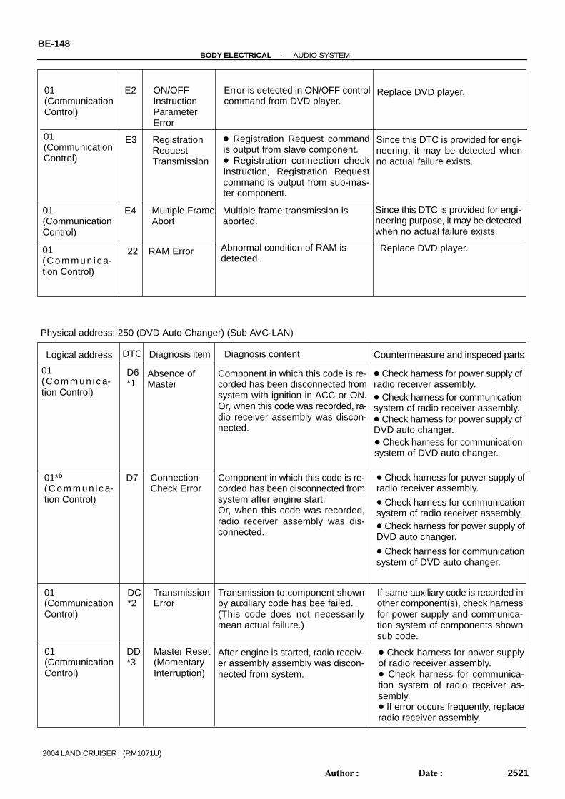
Physical address: 250 (DVD Auto Changer) (Sub AVC-LAN)
01(C o m m u n i c a-tion Control)
D6*1
Absence of Master
Component in which this code is re-corded has been disconnected fromsystem with ignition in ACC or ON.Or, when this code was recorded, ra-dio receiver assembly was discon-nected.
Check harness for power supply ofradio receiver assembly. Check harness for communicationsystem of radio receiver assembly. Check harness for power supply ofDVD auto changer. Check harness for communicationsystem of DVD auto changer.
Logical address DTC Diagnosis item Diagnosis content Countermeasure and inspeced parts
01*6 (C o m m u n i c a-tion Control)
D7 Connection Check Error
Component in which this code is re-corded has been disconnected fromsystem after engine start.Or, when this code was recorded,radio receiver assembly was dis-connected.
Check harness for power supply ofradio receiver assembly.
Check harness for communicationsystem of radio receiver assembly. Check harness for power supply ofDVD auto changer.
Check harness for communicationsystem of DVD auto changer.
Transmission Error
DC*2
01(CommunicationControl)
Transmission to component shownby auxiliary code has bee failed. (This code does not necessarilymean actual failure.)
If same auxiliary code is recorded inother component(s), check harnessfor power supply and communica-tion system of components shownsub code.
Master Reset (Momentary Interruption)
DD*3
01 (CommunicationControl)
Check harness for power supplyof radio receiver assembly. Check harness for communica-tion system of radio receiver as-sembly. If error occurs frequently, replaceradio receiver assembly.
After engine is started, radio receiv-er assembly assembly was discon-nected from system.
BE-148-BODY ELECTRICAL AUDIO SYSTEM
2521Author: Date:
2004 LAND CRUISER (RM1071U)

4245(DVD)
No Disk Readout Disk cannot be read. Inspect disk.
44 DVD error Error is detected in DVD player. Replace radio and player.
45 EJECT error Disk cannot be ejected. Check whether foreign mat-ters enter inspection.
46 Disk Crack A crack and dirt are in a disk.
52 Player Error Clamp unusually generating. DVD player.
45(DVD)
45(DVD)
45(DVD)
45(DVD)
Registration Completion InstructionError
E0*1
01(CommunicationControl)
”Registration Completion Instruc-tion” command fromradio receiverassembly cannot be received.
Since this DTC is provided for engi-neering, it may be detected whenno actual failure exists.
ON/OFF InstructionParameter Error
E201(CommunicationControl)
Error is detected in ON/OFF controlcommand from radio receiver as-sembly.
Replace radio receiver assembly.
Registration Request Transmission
E301(CommunicationControl)
Since this DTC is provided for engi-neering, it may be detected whenno actual failure exists.
Registration Request commandis output from slave component. By reception of connection checkInstruction, Registration Requestcommand is output from sub-mas-ter component.
Master ErrorDF*4
01(CommunicationControl)
Due to defective condition of com-ponent with a display, master func-tion is switched to audio equip-ment . Error occurs in communica-tion between sub-master (audio)and master component.
Check harness for power supplyof radio receiver assembly. Check harness for communica-tion system of radio receiver as-sembly. Check harness for communica-tion system between radio receiverassembly and sub-master compo-nent.
47 DVD High Temp High temperature is detected inDVD auto changer.
45(DVD)
Do not stop the operation for aperiod of time.
48 DVD Excess Current
Excess current is applied toDVD auto changer.
45(DVD)
Replace DVD auto changer.
50 A Malfunction ininsert ion/ejec-tion
Operation malfunction in inser-tion/ ejection.
45(DVD)
Replace DVD auto changer.
51 A Malfunction inswitching disk
Operation malfunction in switchingdisk.
45(DVD)
Replace DVD auto changer.
Inspect disk.
-BODY ELECTRICAL AUDIO SYSTEMBE-149
2522Author: Date:
2004 LAND CRUISER (RM1071U)

BE-150-BODY ELECTRICAL AUDIO SYSTEM
2523Author: Date:
2004 LAND CRUISER (RM1071U)
4. PROBLEM SYSMPTOMS TABLENOTICE:When replacing the internal mechanism (computer part) of the audio system, be careful that no partof your body or clothing comes in contact with the terminals of the leads from the IC, etc. of the re-placement part (spare part).HINT:This inspection procedure is a simple troubleshooting which should be carried out on the vehicle during sys-tem operation and was prepared on the assumption of system component troubles (except for the wires andconnectors, etc.).Always inspect the trouble taking the following items into consideration.
Open or short circuit of the wire harness Connector or terminal connection fault
Problem Flow chart No.
Radio Radio not operating when power switch turned to ’ON’. 1
Display indicates when power switch turned to ’ON’, but no sound (including
’noise’) is produced.2
Noise present, but AM - FM not operating. 3
Any speaker does not work. 4
Any AM or FM does not work. 5
Few preset turning bands. 5
Reception poor. 6
Sound quality poor. 7
Preset memory disappears. 8
Tape Player Cassette tape cannot be inserted. 9
Cassette tape inserted, but no power. 10
Power coming in, but tape player not operating. 11
Any speaker does not work. 12
Sound quality poor. 13
Tape jammed, malfunction with tape speed or auto-reverse. 14
Cassette tape will not eject. 15
CD Player CD cannot be inserted. 16
CD inserted but no power/ 17
Power coming in, but CD player not operating. 18
Sound jumps. 19
Sound quality poor (Volume faint) 20
Any speaker does not work. 21
CD will not be ejected. 22
Power Amplifier No power coming in. 23
Power coming in, but power amplifier not operating. 24
Any speaker does not work. 25
Noise Noise occurs 26
Noise produced by vibration or shock while driving. 27
Noise produced when engine starts. 28
Steering Pad Switch A audio system cannot be operated with steering pad switch. 29
Rear Seat AudioQuality of sound from headphone connected to headphone terminal is poor or no
sound can be heard.30

1 Radio RADIO NOT OPERATING WHEN POWER SWITCH TURNED TO ”ON”
+ B wire harness faulty.
GND faulty.
ACC wire harness faulty.
+B wire harness faulty.
GND faulty.
Is tape player operating normally?
Check if CIG fuse is OK?
Is power supplied to ACC terminal of power amplifier?
Yes
NG
No
OK
No
No
No
No
OK
OK
OK
Yes
Yes
Yes
Yes
NG
NG
NG
Check if RADIO fuse is OK?
Radio assembly faulty.
Replace fuse.
ACC wire harness faulty.
Check if GND (wire harness side) to radio assembly is OK?
Radio assembly faulty.
Replace fuse.
Is power supplied to +B terminal of power amplifier?
Is power supplied to ACC terminal of radio assembly?
Is power supplied to +B terminal of radio assembly?
Check if GND (wire harness side) of power amplifiergrounded normally?
-BODY ELECTRICAL AUDIO SYSTEMBE-151
2524Author: Date:
2004 LAND CRUISER (RM1071U)
The term ”AM” includes LW,MW and SW, and the term ”FW” includes UKW.

2 RadioDISPLAY INDICATES WHEN POWER SWITCH TURNED TO”ON”, BUT NO SOUND (INCLUDING ”NOISE”) IS PRODUCED
+ B wire harness faulty.
GND faulty.
Speaker wire harness faulty.
Is tape player operating normally?
Check if ACC fuse is OK?
Yes
NG
No
OK
No
No
OK
OK
Yes
Yes
NG
NG
Check if AMP fuse is OK?
Radio assembly faulty. Recheck system after repair.
Replace fuse.
ACC wire harness faulty.
Radio assembly faulty.
Replace fuse.
Does continuity exist in speaker wire harness?
Temporarily install another speaker. Functions OK?
Hiss noise from speaker?
Yes
Yes
No
No
No
Yes
Power amplifier faulty.Recheck system after repair.
Speaker faulty.
Is power supplied to ACC terminal of power amplifier?
Check if GND (wire harness side) of power amplifiergrounded normally?
Is power supplied to +B terminal of power amplifier?
BE-152-BODY ELECTRICAL AUDIO SYSTEM
2525Author: Date:
2004 LAND CRUISER (RM1071U)

Speaker wire harness faulty.
Radio assembly faulty.Recheck system after repair.
Temporarily install another speaker? Functions OK?
Power amplifier faulty. Recheck system after repair.
Speaker faulty.
4 Radio ANY SPEAKER DOSE NOT WORK
Is hiss noise produced by non-functioning speaker?
Does continuity exist in speaker wire harness?
Yes
Yes
No
Yes
No
No
3 Radio NOISE PRESENT, BUT AM-FM NOT OPERATING
Go to No.25
Radio faulty.If radio side faulty.
-BODY ELECTRICAL AUDIO SYSTEMBE-153
2526Author: Date:
2004 LAND CRUISER (RM1071U)

5 RadioANY AM OR FM DOES NOR WORK FEW PRESET TUNING BANDS
Problem with radio wave signals or location?
Are both AM and FM defective?
Radio assembly faulty.
Go to No.6
Is power for the antenna being output from the radio assembly?
Poor signals, poor location.
No
Yes
NoYes
Yes
No
BE-154-BODY ELECTRICAL AUDIO SYSTEM
2527Author: Date:
2004 LAND CRUISER (RM1071U)

6 Radio POOR RECEPTION
Is the condition bad in comparison with other vehicles?
Are there any additional installation parts?(Sun shade film, telephone antenna, etc.)
Check if there is any scratch and breaking of a wire onthe glass antenna and the defogger pattern.(visual check. tester)(See page BE-124 )
Is the contact of the plug jack of the radio OK?
Does the condition get better by using the outerantenna (such as pillar antenna)?
Is the contact of the antenna terminal on the glasssurface and the defogger terminal?
Is the continuity of the antenna cord OK?
Check the grounding of the antenna, antenna cord.
Does the condition get better by replacing theantenna cord?
Take a measure for contact.
An electric wave environment is bad.
Does the condition get better ifremoving them?
Influence of additional installation parts.
Repair. (See page BE-75 )
Check the radio.
Take a measure for contact.
Grounding failure.
Replace the antenna cord.
Replace the antenna cord.
YesNo
Radio assembly faulty
Yes
Yes
Yes
Yes
Yes
Yes
Yes
No
No
No
No
No
No
No
NGOK
Yes
-BODY ELECTRICAL AUDIO SYSTEMBE-155
2528Author: Date:
2004 LAND CRUISER (RM1071U)
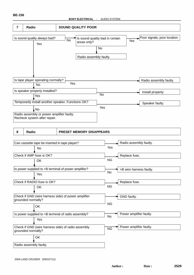
7 Radio SOUND QUALITY POOR
YesNo Yes
NGOK
Is sound quality always bad?
Radio assembly faulty.
Poor signals, poor location.
Install properly.
Speaker faulty.
Is tape player operating normally?
Is speaker properly installed?
Radio assembly or power amplifier faulty.Recheck system after repair.
Temporarily install another speaker. Functions OK?
Is sound quality bad in certainareas only?
Can cassette tape be inserted in tape player?
Check if AMP fuse is OK?
Radio assembly faulty.
Replace fuse.
+B wire harness faulty.
GND faulty.
Power amplifier faulty.
8 Radio PRESET MEMORY DISAPPEARS
No
Radio assembly faulty.No
No
No
Yes
Yes
Power amplifier faulty.
Radio assembly faulty.
Yes
Yes
YesNo
No
No
NG
NG
OK
OK
Yes
Check if GND (wire harness side) of power amplifiergrounded normally?
Is power supplied to +B terminal of power amplifier?
Check if GND (wire harness side) of radio assemblygrounded normally?
Is power supplied to +B terminal of radio assembly?
Check if RADIO fuse is OK? Replace fuse.NGOK
BE-156-BODY ELECTRICAL AUDIO SYSTEM
2529Author: Date:
2004 LAND CRUISER (RM1071U)

9 Tape Player CASSETTE TAPE CANNOT BE INSERTED
Yes
NG
Is there a foreign object inside tape player?
Is auto search button radio operating normally?
Check if RADIO fuse is OK?
Radio assembly faulty.
Radio assembly faulty.
Remove foreign object.
Replace fuse.
+B wire harness.
Yes
No
No
OK
Yes
OK
No
NG
10 Tape Player CASSETTE TAPE INSERTED, BUT NO POWER
Is radio operating normal?
Check if ACC fuse is OK?
Check if RADIO fuse is OK?
Radio assembly faulty.
Replace fuse.
Replace fuse.
+B wire harness faulty.
ACC wire harness.
Radio assembly faulty.
No
No
No
OK
OK
Yes
Yes
Yes
NG
NG
Check if GND (wire harness side) of radio assemblygrounded normally?
Is power supplied to +B terminal of radio assembly?
Is power supplied to +B terminal of radio assembly?
Is power supplied to ACC terminal of radio assembly?
GND faulty.
-BODY ELECTRICAL AUDIO SYSTEMBE-157
2530Author: Date:
2004 LAND CRUISER (RM1071U)

11 Tape Player POWER COMING IN, BUT TAPE PLAYER NOT OPERATING
Yes
No
Radio assembly faulty.
Cassette tape faulty.
Speaker wire harness faulty.
Speaker faulty.
Power amplifier faulty.Recheck system after repair.
Yes
No
No
Yes
YesNo
No
Function OK if different cassette tape inserted?
Is radio operating normally?
Does continuity exist in speaker wire harness?
Temporarily install another speaker.Function OK?
Hiss noise from speaker?
Radio assembly faulty.Recheck system after repair.
Yes
Radio assembly faulty.Recheck system after repair.
Radio assembly faulty.
No
No
No
Yes
Yes
Yes
Yes
No
Is radio operating normally?
Speaker wire harness faulty.
Speaker faulty.
Is hiss noise produced by non-functioning speaker.
Does continuity exist in speaker wire harness?
Temporarily install another speaker.Function OK?
Radio assembly or power amplifier faulty.
12 Tape Player ANY SPEAKER DOES NOT WORK
BE-158-BODY ELECTRICAL AUDIO SYSTEM
2531Author: Date:
2004 LAND CRUISER (RM1071U)
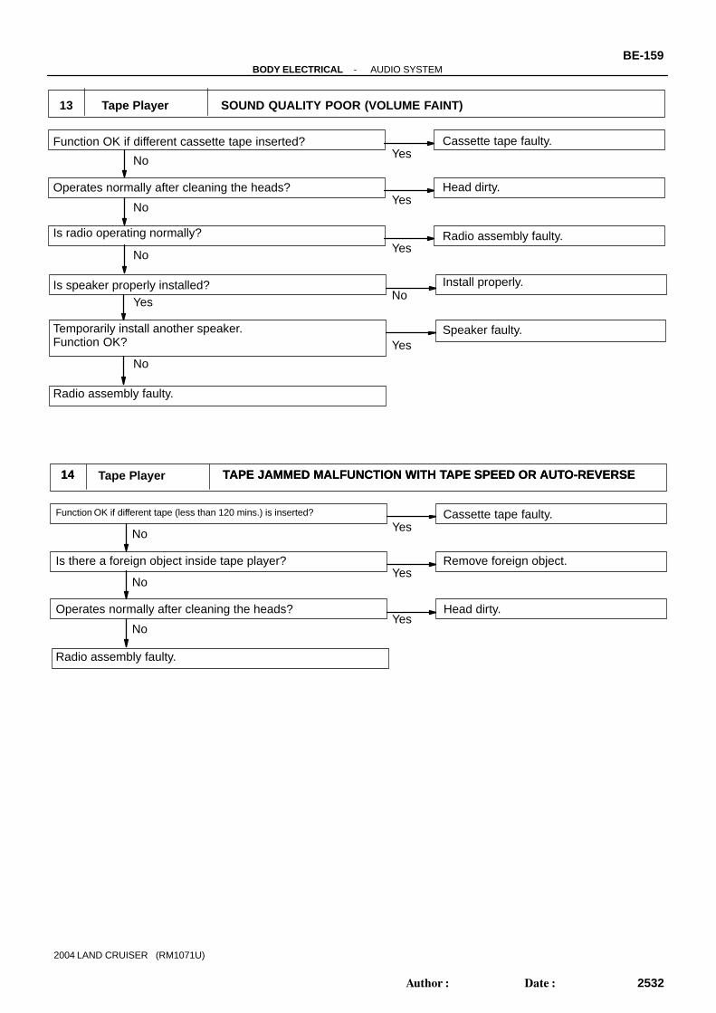
13 Tape Player SOUND QUALITY POOR (VOLUME FAINT)
Yes
No
Radio assembly faulty.
Cassette tape faulty.
Install properly.
Speaker faulty.
Head dirty.Yes
No
No
Yes
Yes
No
No
Function OK if different cassette tape inserted?
Is radio operating normally?
Is speaker properly installed?
Temporarily install another speaker.Function OK?
Radio assembly faulty.
Operates normally after cleaning the heads?
Yes
Function OK if different tape (less than 120 mins.) is inserted?
Operates normally after cleaning the heads?
Radio assembly faulty.
Is there a foreign object inside tape player?
Cassette tape faulty.
Remove foreign object.
Head dirty.
14 TAPE JAMMED MALFUNCTION WITH TAPE SPEED OR AUTO-REVERSE
No
No
No
Yes
Yes
Yes
14 Tape Player TAPE JAMMED MALFUNCTION WITH TAPE SPEED OR AUTO-REVERSE
-BODY ELECTRICAL AUDIO SYSTEMBE-159
2532Author: Date:
2004 LAND CRUISER (RM1071U)

15 Tape Player CASSETTE TAPE WILL NOT BE EJECTED
Radio assembly faulty.
Is tape player operating normally?
Is auto search button of radio operating normally?
Check if RADIO fuse is OK?
Cassette tape jammed.
Replace fuse.
+B wire harness.
Yes
Yes
YesNo
No
No
NGOK
Radio assembly faulty.
16 CD Player CD CANNOT BE INSERTED
YesNo
Is CD already inserted? Eject CD.
Radio assembly faulty.
Replace fuse.
+B wire harness faulty.
Check if RADIO fuse is OK?
Radio assembly faulty.
Is auto search button of radio operating normally?
No
Yes
Yes No
OK
NG
OK
NG
Check if GND (wire harness side) of radio assemblygrounded normally?
Is power supplied to +B terminal of radio receiver?
Is power supplied to +B terminal of radio assembly?
ACC wire harness faulty.
Yes NoIs power supplied to ACC terminal of radio assembly?
GND wire harness faulty.
BE-160-BODY ELECTRICAL AUDIO SYSTEM
2533Author: Date:
2004 LAND CRUISER (RM1071U)

17 CD Player CD INSERTED, BUT NO POWER
Radio assembly faulty.
Replace fuse.Check if ACC fuse is OK?
Is radio operating normally?
ACC wire harness faulty.
Radio assembly faulty.
No
No
Yes
Yes
OK NG
18 CD Player POWER COMING IN, BUT CD PLAYER NOT OPERATING
Is CD inserted with correct side up?
Is radio operating normally?
Insert correctly.
CD faulty.
Protective circuit inoperation.
Function OK if different CD inserted?
Has sudden temperature changeoccurred inside cabin?
Radio assembly faulty.
Is temperature inside cabin hot?
No
Yes
Yes
Yes Yes
Yes
No
No No
No
Formation ofcondensationdue to temp. changes.
Is power supplied to ACC terminal of radio assembly?
Go to No.2.
-BODY ELECTRICAL AUDIO SYSTEMBE-161
2534Author: Date:
2004 LAND CRUISER (RM1071U)

CD Player SOUND JUMPS19
Radio assembly faulty.
Does sound jump only during strong vibration?
Is CD player properly installed?
Functions OK if different CD inserted?
Has sudden temperature change occurred inside cabin?
Jumping caused by vibration.
Install properly.
CD faulty.
Formation of condensation due totemp. changes.
Yes
Yes
Yes
Yes
No
No
No
No
20 CD Player SOUND QUALITY POOR (VOLUME FAINT)
Is radio operating normally?
CD faulty.Function OK if different CD inserted?
Speaker faulty.Temporarily install another speaker.Functions OK?
Yes
No
Is speaker property installed?
Radio assembly faulty.
Install properly.
Yes
Yes
Yes
No
No
No
Radio assembly or power amplifier faulty.
BE-162-BODY ELECTRICAL AUDIO SYSTEM
2535Author: Date:
2004 LAND CRUISER (RM1071U)

Radio assembly faulty.
Power amplifier faulty.Recheck system after repair.
Temporarily install another speaker.Function OK?
21 CD Player ANY SPEAKER DOES NOT WORK
Speaker wire harness faulty.
Speaker faulty.
Is hiss noise produced by non-functioning speaker?
Does continuity exist in speaker wire harness?
Is radio operating normally?
Yes
Yes
Yes
Yes
No
No
No
No
Radio assembly faulty.Recheck system after repair.
22 CD Player CD WILL NOT BE EJECTED
Is auto search button of radiooperating normally?
No
Radio assemblyfaulty.
Replace fuse.
+B wire harness faulty.
Radio assembly faulty.
Check if RADIO fuse is OK?
No
Yes
NGOK
Yes
Is power supplied to +B terminal of radio receiver?
-BODY ELECTRICAL AUDIO SYSTEMBE-163
2536Author: Date:
2004 LAND CRUISER (RM1071U)

23 Power Amplifier NO POWER COMING IN
+ B wire harness faulty.
GND faulty.
Speaker wire harness faulty.
Is tape player operating normally?
Check if ACC fuse is OK?
Yes
NG
No
OK
No
No
No
OK
OK
Yes
Yes
Yes
NG
NG
Check if AMP fuse is OK?
Replace fuse.
ACC wire harness faulty.
Radio assembly faulty.
Replace fuse.
Check if GND (wire harness side) of power amplifiergrounded normally?
Is power supplied to ACC terminal of power amplifier?
Is power supplied to +B terminal of power amplifier?
Does continuity exist in speaker wire harness.
Temporarity install another speaker functions OK?
Power amplifier faulty.
Speaker faulty.
NoYes
BE-164-BODY ELECTRICAL AUDIO SYSTEM
2537Author: Date:
2004 LAND CRUISER (RM1071U)

24 Power AmplifierPOWER COMIMG IN, BUT WOOFER (POWER) AMPLIFIER NOTOPERATING
+ B wire harness faulty.
GND faulty.
ACC wire harness faulty.
Speaker wire harness faulty.
GND faulty.
Is tape player operating normally?
Check if ACC fuse is OK?
Yes
NG
No
OK
No
No
No
No
OK
OK
OK
Yes
Yes
Yes
Yes
NG
NG
NG
Check if RADIO, AMP fuse is OK?
Radio assembly faulty. Recheck system after repair.
Replace fuse.
ACC wire harness faulty.
Radio assembly faulty.
Replace fuse.
Is there continuity in speaker wire harness?
Temporarily install another speaker. Functions OK?
Hiss noise from speaker?
Yes
Yes
No
No
No
Yes
+B wire harness faulty.
Power amplifier faulty.Recheck system after repair.
Speaker faulty.
Is power supplied to ACC terminal of power amplifier?
Check if GND (wire harness side) of power amplifiergrounded normally?
Is power supplied to +B terminal of power amplifier?
Is power supplied to ACC terminal of radio assembly?
Is power supplied to +B terminal of radio assembly?
Check if GND (wire harness side) of radio assemblygrounded normally?
-BODY ELECTRICAL AUDIO SYSTEMBE-165
2538Author: Date:
2004 LAND CRUISER (RM1071U)

Radio assembly faulty.
Power amplifier faulty.Recheck system after repair.
Temporarily install another speaker.Function OK?
25 Power Amplifier ANY SPEAKER DOES NOT WORK
Speaker wire harness faulty.
Speaker faulty.
Is hiss noise produced by non-functioning speaker?
Does continuity exist in speaker wire harness?
Is radio operating normally?
Yes
Yes
Yes
Yes
No
No
No
No
Radio assembly faulty.Recheck system after repair.
BE-166-BODY ELECTRICAL AUDIO SYSTEM
2539Author: Date:
2004 LAND CRUISER (RM1071U)

26 Noise NOISE OCCURS
NoYes
Does the noise occur only in the radio?
Does the noise occur in a particular place?
Is there any additional installation partaround the glass imprinted antenna?(Sun shade film, telephone antenna etc.)
Does the noise occur even pulling out theantenna cord from the radio?
Does the noise occur even after pulling out theantenna terminal on the glass surface?
Isn’t there any adhesive (Butyl rubber)stuck on the bases of the antennaterminal, defogger terminal and bus bar?
Does the condition get better by replacingthe antenna cord.
Noise rediates directly to the antenna from thegeneration source.
Replace the antenna cord.
Failure of glass installation.Must plane the butyl rubber.
Noise mixing into the antenna cable.
Check the radio.
Influence of the film or the noise radiationof the additional installation part.
Does the noise stop by removing it?
An electric environment.
Refer to No.27.(It occurs in the cassette and CD.)
Yes
Yes
Yes
Yes
Yes
Yes
No
No
No
No
No
No
-BODY ELECTRICAL AUDIO SYSTEMBE-167
2540Author: Date:
2004 LAND CRUISER (RM1071U)

27 Noise NOISE PRODUCED BY VIBRATION OR SHOCK WHILE DRIVING
NoYes
Is radio assembly properly installed?
Noise is produced from static eletricity accumulating in the vehicle body.
With vehicles stationary lightly tap each system.Is noise produced?
Install properly.
Each system faulty.
Is speaker properly installed?No
No
Yes
Yes
28 Noise NOISE PRODUCED WHEN ENGINE STARTS
No
YesWhistling noise which becomes high-pitched whenaccelerator strongly depressed, disappears shortlyafter engine stops.
Generator noise.
A/C noise.
Fuel gauge noise.
Horn noise.
Ignition noise.
Turn signal noise.
Washer noise.
Engine coolant temp. gauge noise.
Wiper noise.
Whining noise occurs when A/C is operating.
Scratching noise occurs during sudden acceleration, driving on roughroads or when ignition switch is turned ON.
Clicking sound is heard when horn button is pressed, thenreleased. Whirring/grating sound is heard when pushedcontinuously.
Murmuring sound stops when engine stops.
Tick-tack noise occurs in co-ordination with blinkingofflasher.
Noise occurs during window washer operation.
Scratching noise occurs while engine is running,and continues a while even after engine stops.
Scraping noise in line with wiper beat.
Other type of noise
Yes
Yes
Yes
Yes
Yes
Yes
Yes
Yes
No
No
No
No
No
No
No
No
BE-168-BODY ELECTRICAL AUDIO SYSTEM
2541Author: Date:
2004 LAND CRUISER (RM1071U)

29 Steering Pad Switch A AUDIO SYSTEM CANNOT BE OPERATED WITH STEERING PADSWITCH
NoYes
Resistance of steering pad switch is OK? Steering pad switch faulty.
Wire harness faulty.Is wire harness between radio assembly and steering pad switch OK? No
Yes
30 Rear Seat Audio QUALITY OF SOUND FROM HEADPHONE TERMINAL IS POOR OR NO SOUNDCAN BE HEARD
NoYes
Temporarity install another headphone. Function OK? Headphone faulty.
Wire harness faulty.
RSA panel faulty.
Is wire harness between radio assembly and RSA panel OK?
YesNo
Radio assembly faulty.
Temporarity install another RSA panel. Function OK?
Radio assembly faulty.
No
Yes
-BODY ELECTRICAL AUDIO SYSTEMBE-169
2542Author: Date:
2004 LAND CRUISER (RM1071U)

BE01I-05
-BODY ELECTRICAL BODY ELECTRICAL SYSTEMBE-1
2374Author: Date:
2004 LAND CRUISER (RM1071U)
BODY ELECTRICAL SYSTEMPRECAUTIONHINT:Take care to observe the following precautions when performing inspections or removal and replacementof body electrical related parts.
1. HEADLIGHT SYSTEMHalogen bulbs have pressurized gas inside and require special handling. They can burst if scratched ordropped. Hold a bulb only by its plastic or metal case. Don’t touch the glass part of a bulb with bare hands.
2. SRS (SUPPLEMENTAL RESTRAINT SYSTEM)The LAND CRUISER is equipped with an SRS (Supplemental Restraint System) such as the driver airbagand front passenger airbag. Failure to carry out service operation in the correct sequence could cause theSRS to unexpectedly deploy during servicing, possibly leading to a serious accident. Before servicing (in-cluding removal or installation of parts, inspection or replacement), be sure to read the precautionary noticesin the RS section.
3. AUDIO SYSTEM If the negative (-) terminal cable is disconnected from the battery, the preset AM, FM 1 and FM 2 sta-
tions stored in memory are erased, so be sure to note the stations and reset them after the negative(-) terminal cable is reconnected to the battery.
If the negative (-) terminal cable is disconnected from the battery, the ”ANTI-THEFT SYSTEM” willoperate when the cable is reconnected, but the radio, tape player and CD player will not operate. Besure to input the correct ID number so that the radio, tape player and CD player can be operated again.
4. MOBILE COMMUNICATION SYSTEMIf the vehicle is equipped with a mobile communication system, refer to precautions in the IN section.

BE0GX-11
BE-48-BODY ELECTRICAL BACK-UP LIGHT SYSTEM
2421Author: Date:
2004 LAND CRUISER (RM1071U)
INSPECTIONINSPECT PARK/ NEUTRAL POSITION SWITCH CONTINUITY (See page DI-402 )

BE0GW-12
I24740
Ignition Switch
Cowl Side J/B LH GAUGE1 Fuse
Back-up Light
Park/Neutral Position Switch
Cowl Side J/B RH GAUGE2 Fuse
-BODY ELECTRICAL BACK-UP LIGHT SYSTEMBE-47
2420Author: Date:
2004 LAND CRUISER (RM1071U)
BACK-UP LIGHT SYSTEMLOCATION

BE0S0-04
I25532
Connector ”A”Connector ”D” Connector ”C” Connector ”B”
BE-58-BODY ELECTRICAL COMBINATION METER
2431Author: Date:
2004 LAND CRUISER (RM1071U)
CIRCUIT

I24919
OIL
SEAT BELTD1
D2
ODO/TRIP
INCLINATION SSR
EEPRON
BZ
SPD
TM
FUEL
TEMP
VOLT
SUPPLY CIRCUIT
P
R
D
N
4
3
L
2
A/T P
CRUISE
2nd START
ETC PWR
AIR BAG
FUEL WARNING
CHG
A/T OIL TEMP
D6
D11
D5
D19
D14
D16
D12
C19
B10
C20
C4
D10
D9
D17OIL MAINT
-BODY ELECTRICAL COMBINATION METERBE-59
2432Author: Date:
2004 LAND CRUISER (RM1071U)

I24920
BEAM
TURN-R
TURN-LCENTER DIFF LOCK
VSC TRAC
VSC OFF
SLIP
ABS
RSCA
CHECK ENG
A1
DOOR
A7
A5
A6
D4
B18
D3
C7
C8
C14
C15
D20
A8
A4
B4
B6
B13
B7
C11
B12
B5
B8
A19
C12
C13
C10
B9
B1
TRAC
BRK
BE-60-BODY ELECTRICAL COMBINATION METER
2433Author: Date:
2004 LAND CRUISER (RM1071U)

MET FuseLight Control SwitchFlasher Relay
ABS, TRC, VSC ECUABS, TRC, VSC ECUDrive Monitor
H/L R-HI Fuse
Body ECU
ABS, TRC, VSC ECU
ABS & BA & TRAC & VSC Actuator
ECM
ABS, TRC, VSC ECU
Airbag ECU
Oil Pressure Sender GaugeAirbag ECUBody ECU
Wiring connector sideNo.
1076
191817
5
3
12
20
1516171819
741
C14
C13
C12
11
Gateway ECUECM
Engine GroundMain Fuel Sender Gauge
7
1920
124
C15
Key Unlock Warning Switch9
CTR DIFF Switch14
Drive Monitor16
10 ECM
Body (Door Courtesy Switch Signal)10
Flasher Relay4
ABS, TRC, VSC ECUABS, TRC, VSC ECUABS, TRC, VSC ECU
GAUGE1 FuseECU-B2 FuseACC FuseDOME FuseSpeed Sensor
1112131415
Main Fuel Sender Gauge
Light Control Rheostat6 Main Fuel Sender Gauge
Body Ground9
Speed Control Unit16
PANEL Fuse8
11 Driver Seat Belt Buckle Switch
-BODY ELECTRICAL COMBINATION METERBE-61
2434Author: Date:
2004 LAND CRUISER (RM1071U)

BE0HJ-11
I24912
Meter Cover
Inclination Sensor
Meter Glass
BE-62-BODY ELECTRICAL COMBINATION METER
2435Author: Date:
2004 LAND CRUISER (RM1071U)
COMPONENTS

BE2EF-01
1
2
3
4
5
6
7
8
9
10
12
13
14
15
16
17
18
19
20
11 20
19
18
17
16
15
14
13
12
11
10
9
8
7
6
5
4
3
2
1
1
2
3
4
5
6
7
8
9
10
12
13
14
15
16
17
18
19
20
11 20
19
18
17
16
15
14
13
12
11
10
9
8
7
6
5
4
3
2
1
I29077
Connector C15 Connector C14 Connector C13 Connector C12
-BODY ELECTRICAL COMBINATION METERBE-63
2436Author: Date:
INSPECTION1. INSPECT COMBINATION METER CIRCUITConnect the connector C12, C13, C14 and C15 to the combina-tion meter and inspect the wire harness side connectors fromthe back side as shown in the table.
Tester connection Condition Specified condition
C12 3 (DOOR ) G dEither door is opened Below 1 V
C12-3 (DOOR-) - GroundEither door is closed 10 - 14 V
C12 4 (TURN L) G d
Ignition switch ON and
turn signal switch OFF or RIGHTBelow 1 V
C12-4 (TURN-L) - GroundIgnition switch ON and
turn signal switch LEFT
Pulse signal is output
10 - 14 V ↔ Below 1 V
C12 5 (BEAM ) G dIG switch ON, light control switch OFF Below 1 V
C12-5 (BEAM+) - GroundIG switch ON, light control switch ON 10 - 14 V
C12 6 (TURN R) G d
Ignition switch ON and
turn signal switch OFF or LEFTBelow 1 V
C12-6 (TURN-R) - GroundIgnition switch ON and
turn signal switch RIGHT
Pulse signal is output
10 - 14 V ↔ Below 1 V
C12-7 (BEAM-) - Ground IG switch ON, light control switch ON Below 1 V
C12 10 (CHG ) G dIgnition switch OFF Below 1 V
C12-10 (CHG+) - GroundIgnition switch ON 10 - 14 V
C12 12 (ABS) G d
Ignition switch ON and ABS warning light lights
upBelow 1 V
C12-12 (ABS) - GroundIgnition switch ON and
ABS warning light does not light up10 - 14 V
C13 8 (ILL ) G dIG switch OFF Below 1 V
C13-8 (ILL+) - GroundIG switch ON 10 - 14 V

BE-64-BODY ELECTRICAL COMBINATION METER
2437Author: Date:
C13 11 (CHECK E/G) G dIgnition switch ON and engine is stopped Below 1 V
C13-11 (CHECK E/G) - GroundIgnition switch ON and engine is running 10 - 14 V
C13-14 (CTR DIFF/4WD) - GroundIgnition switch ON and
center diff. lock switch OFFBelow 1 V
C13-14 (CTR DIFF/4WD) - GroundIgnition switch ON and
center diff. lock switch ON10 - 14 V
C13 15 (SLIP) G dIG switch ON, SLIP warning light ON Below 1.5 V
C13-15 (SLIP) - GroundIG switch ON, SLIP warning light OFF 10 - 14 V
C13 16 (VSC TRC) G dIG switch ON, VSC TRC indicator light ON Below 1.5 V
C13-16 (VSC TRC) - GroundIG switch ON, VSC TRC indicator light OFF 10 - 14 V
C13 17 (VSC OFF) G dIG switch ON, VSC OFF indicator light ON Below 1.5 V
C13-17 (VSC OFF) - GroundIG switch ON, VSC OFF indicator light OFF 10 - 14 V
C13 18 (ACTIVE TRC) G dIG switch ON, TRC OFF indicator light ON Below 1.5 V
C13-18 (ACTIVE TRC) - GroundIG switch ON, TRC OFF indicator light OFF 10 - 14 V
C13 19 (RSCA OFF) G dIG switch ON, RSCA warning light ON Below 2.0 V
C13-19 (RSCA OFF) - GroundIG switch ON, RSCA warning light OFF 10 - 14 V
C14-4 (AIR BAG-) - GroundIgnition switch ON and
SRS indicator light lights upBelow 1 V
C14-4 (AIR BAG-) - GroundIgnition switch ON and
SRS indicator does not light up10 - 14 V
C14 7 (OIL PRS SDR) G dIgnition switch ON and indicator ON Below 1 V
C14-7 (OIL PRS SDR) - GroundIgnition switch ON and indicator OFF 10 - 14 V
C14-10 (T/M PULSE) - Ground Engine is Running Pulse generation
C14 11 (D BKL SW) G dIgnition switch ON and seat belt is unfastened 10 - 14 V
C14-11 (D-BKL SW) - GroundIgnition switch ON and seat belt is fastened Below 1 V
C14 18 (PKB SW) G d
Ignition switch ON and
parking brake lever is pulledBelow 1 V
C14-18 (PKB SW) - GroundIgnition switch ON and
parking brake lever is released10 - 14 V
C14 20 (BRAKE) G d
Ignition switch ON and brake system indicator
ONBelow 1 V
C14-20 (BRAKE) - GroundIgnition switch ON and brake system indicator
OFF10 - 14 V
C15-1 (E/G EARTH) - Ground Constant Continuity
C15-2 (MAIN FE) - Ground Constant Continuity
C15-4 (MAIN FV) - Ground Ignition switch ON 4.5 - 5.5 V
C15 6 (MAIN FR) G d
Ignition switch ON and
fuel sender gauge float UPApprox. 0.5 V
C15-6 (MAIN FR) - GroundIgnition switch ON and
fuel sender gauge float DOWNApprox. 5.5 V
C15 7 (ILL ) G d
Ignition switch ON and
light control rheostat volume minimumBelow 1 V
C15-7 (ILL-) - GroundIgnition switch ON and
light control rheostat volume maximum10 - 14 V
Key unlock warning switch ON (Key is inserted) Below 1 V
C15-9 (KEY SW) - Ground Key unlock warning switch OFF
(Key is removed)10 - 14 V

-BODY ELECTRICAL COMBINATION METERBE-65
2438Author: Date:
C15 10 (D CTY SW) G dIgnition switch ON and driver door is opened Below 1 V
C15-10 (D-CTY SW) - GroundIgnition switch ON and driver door is closed 10 - 14 V
C15 11 (IGN ) G dIgnition switch OFF Below 1 V
C15-11 (IGN+) - GroundIgnition switch ON 10 - 14 V
C15-12 (ECU-B2) - Ground Constant 10 - 14 V
C15 13 (ACC ) G dIgnition switch OFF Below 1 V
C15-13 (ACC+) - GroundIgnition switch ACC or ON 10 - 14 V
C15-14 (DOOR+) - Ground Constant 10 - 14 V
C15-15 (SP IN) - Ground Ignition switch ON and slowly move the wheelPulse signal is output below 1.5 V ↔battery positive voltage
C15-16 (4P OUT) - Ground Ignition switch ON and slowly move the wheelPulse signal is output below 1.5 V ↔ approx. 5 V
or below 1.5 V ↔ battery positive voltage
If a circuit is not as specified, inspect the applicable circuit.2. INSPECT SPEEDOMETER/ ON-VEHICLEUsing a speedometer tester, inspect the speedometer for allow-able indication error and check the operation of the odometer.HINT:Tire wear and tire over or under inflation will increase the indica-tion error.
USA (mph) CANADA (km/h)
Standard indication Allowable range Standard indication Allowable range
20 18 - 24 20 17 - 24
40 38 - 44 40 38 - 46
60 56 - 66 60 57.5 - 67
80 78 - 88 80 77 - 88
100 98 - 110 100 96 - 109
120 118 - 132 120 115 - 130
140 134 - 151.5
160 153 - 173
If error is excessive, replace the combination meter.

I24950
Connector C15
16
1
3 2 1
I25536
BE-66-BODY ELECTRICAL COMBINATION METER
2439Author: Date:
3. INSPECT SPEEDOMETER VOLTAGE(a) While driving the vehicle at the speed of 10 km/h, check
the voltage between the terminals 16 and 1 of the com-bination meter assy.STANDARD: Fluctuation between 10 to 14 V or less isrepeated 7 times within 1 sec.
4. INSPECT VEHICLE SPEED SENSOR OPERATION(a) Connect the positive (+) lead from the battery to terminal
1 and negative (-) lead to terminal 2.(b) Connect the positive (+) lead from the tester to terminal
3 and the negative (-) lead to terminal 2.(c) Rotate the shaft.(d) Check that there is voltage change from approx. 0V to 11
V or more between terminals 2 and 3.HINT:The voltage change should be performed 4 times for every rev-olution is not as specified, replace the sensor.5. INSPECT TACHOMETER / ON-VEHICLE(a) Connect a tune-up test tachometer, and start the engine.(b) Compare the tester and tachometer indications.DC 13.5 V 25 °C at (77°F):
Standard indication (rpm)Allowable range (rpm)
( ): estimated reference values
700 630 - 770
1,000 900 - 1,100
2,000 1,850 - 2,150
3,000 2,800 - 3,200
4,000 3,800 - 4,200
5,000 4,800 - 5,200
6,000 5,750 - 6,250
7,000 6,700 - 7,300

I06184
F1/2
E
3 2
1
-BODY ELECTRICAL COMBINATION METERBE-67
2440Author: Date:
6. INSPECT FUEL SENDER GAUGE VOLTAGE(a) Apply voltage (4.5 V - 5.0 V) between terminals 2 and 3.(b) Measure voltage between terminals 1 and 2 for each float
position.
Float position mm (in.) Voltage (V)
F: Approx. 85.3 (3.36) Approx. 4.60 ± 0.1
1/2: Approx. 1.7 (0.67) Approx. 2.45 ± 0.1
E: Approx. 91.9 (3.62) Approx. 0.30 ± 0.1
If voltage value is not as specified, replace main sender gauge.7. INSPECT LOW OIL PRESSURE WARNING LIGHT(a) Disconnect the connector from the low oil pressure
switch.(b) Turn the ignition switch ON.(c) Connect the terminal of wire harness side connector and
ground, then check the warning light.
8. INSPECT PARKING BRAKE WARNING LIGHT(a) Disconnect the connector from the parking brake switch
and ground terminal on the wire harness side connector.(b) Turn the ignition switch ON and check that the warning
light lights up.9. INSPECT BRAKE WARNING LIGHT(a) Disconnect the connector from the brake fluid level warn-
ing switch and ground terminal on the wire harness sideconnector.
(b) Turn the ignition switch ON and check that the warninglight lights up.
10. INSPECT BRAKE FLUID LEVEL WARNING SWITCH(a) Remove the reservoir tank cap and retainer.(b) Disconnect the connector.(c) Check that the continuity exists between the terminal.(d) Use syphon, etc., to take fluid out of the reservoir tank.(e) Check that the continuity exists between terminals.(f) Pour the fluid back in the reservoir tank.11. INSPECT OPEN DOOR WARNING LIGHT(a) DIsconnect the connector from the driver door courtesy
switch and ground terminal on the wire harness side con-nector.
(b) Turn the ignition switch ON and check that the warninglight lights up.

I24949
121
11
Connector C15 Connector C14
I24950
121
9
10
Connector C15
I04107
1 2
4
OFF
ON
I04108
Wire Harness Side:
BE-68-BODY ELECTRICAL COMBINATION METER
2441Author: Date:
12. INSPECT SEAT BELT WARNING BUZZER(a) Disconnect the connector from the combination meter.(b) Connect the positive (+) lead from the battery terminal 12
and negative (-) lead terminal 1.(c) Check that the buzzer stop after 4 to 8 seconds.(d) Check that the buzzer stops when connecting the termi-
nal 11 to the GND.
13. INSPECT KEY UNLOCK WARNING BUZZER(a) Disconnect the connector from the combination meter.(b) Connect the positive (+) lead from the battery terminal 12
and negative (-) lead terminal 1.(c) Connect the negative (-) lead from battery terminal 9 and
10, check that the buzzer sound.
14. INSPECT SEAT BELT WARNING LIGHT(a) DIsconnect the connector from the seat belt buckle switch
and ground terminal on the wire harness side connector.(b) Turn the ignition switch ON and check that the warning
light lights up.
15. INSPECT SEAT BELT BUCKLE SWITCH CONTINUITY
Tester connectionBelt fastened
(Belt unfastened)
Seat belt buckle SW (D) 1 - 4 ON (OFF)
Seat belt buckle SW (P) 2 - 4 OFF (ON)
If operation is not as specified, replace the switch.
16. INSPECT SEAT BELT BUCKLE SWITCH CIRCUITDisconnect the switch connector and inspect the connector onwire harness side, as shown.

I04109
Press Seat Lower Cushion
Sensing part
I24953
-BODY ELECTRICAL COMBINATION METERBE-69
2442Author: Date:
Tester connection Condition Specified condition
4 - Ground Constant Continuity
If continuity is not as specified, inspect the ground circuit.
17. Passenger seat only:INSPECT SEAT BELT WARNING OCCUPANT DETEC-TION SENSOR CONTINUITY
Check that continuity exists between the terminals 1 and 2when pressing the sensing part of the lower seat cushion.If operation is not as specified, replace the sensor.
18. INSPECT LIGHT CONTROL RHEOSTAT(a) Turn the rheostat knob OFF, and check that there is no
continuity between terminal 5 and 4 (Rheostat knobturned to fully counterclockwise).
(b) Gradually, turn the rheostat knob from the dark side tobright side, and check that there is continuity between ter-minal 5 and 4 (Rheostat knob turned to clockwise).
If operation is not as specified, replace the rheostat.

I25813
1
2
3
4
5
6
7
8
9
10
12
13
14
15
16
17
18
19
20
11
I29078
Inclination Sensor
IGN+E/G EARTH
OUT Vcc GND
Bottom Surface of Sensor
Connector C15
BE-70-BODY ELECTRICAL COMBINATION METER
2443Author: Date:
19. INSPECT INCLINATION SENSOR(a) The inclination sensor is installed in the combination me-
ter. Inspect the inclination sensor by connecting a batterypositive (+) lead to terminal 11 (IGN+) of the meter con-nector, and a battery negative (-) lead to terminal 1 (E/GEARTH).
(b) Check if the voltage between terminal Vcc and GND of theinclination sensor connector is 5 V.
(c) Check the voltage between terminal OUT and GND whenthe bottom surface of the inclination sensor is in a levelposition. Also check the voltage when it is inclined back-ward or forward.Standard Value:Bottom surface of sensor is set in a level position: about 4.5 VBottom surface of sensor is inclined:about 0.5 V

BE0HH-12
I24743I10004
Brake Master Cylinder Brake Fluid Level Warning Switch
Cowl Side J/B LH GAUGE1 Fuse ACC Fuse
Seat Belt Buckle Switch
Parking Brake Switch
Light Control Rheostat Combination Meter Assembly
Ignition Switch
Cowl Side J/B RH GAUGE2 Fuse METER Fuse DOME Fuse ECU-B2 Fuse
BE-56-BODY ELECTRICAL COMBINATION METER
2429Author: Date:
2004 LAND CRUISER (RM1071U)
COMBINATION METERLOCATION

I24744
Seat Belt WarningOccupant Detection Sensor
Fuel Tank Fuel Sender Gauge
Park/ Neutral Position Switch
Engine CoolantTempareture Sender Gauge
Speed SensorOil Pressure Gauge
-BODY ELECTRICAL COMBINATION METERBE-57
2430Author: Date:
2004 LAND CRUISER (RM1071U)

BE1Z9-01
Mode Select Switch On DurationNormal Mode
Pressed for 3 sec.
6. Compass Non-display Mode
Pressed for 6 sec.
7. Zone Setting Mode
Ignition switch ON.
Pressed for 9 sec.
Zone area +1Mode Select Switch ON
8. Calibration Mode
Leaving it untouched for a while
Normal Mode
-BODY ELECTRICAL COMPASSBE-71
2444Author: Date:
2004 LAND CRUISER (RM1071U)
COMPASSPRE-CHECK1. SELECTING COMPASS DISPLAY MODEThe mode select switch allows you to select a Display or Non-display mode of the compass.The mode select is operated by the automatic glare-proof / non-glare proof switch on the inner mirror.2. SETTING ZONEDeviation between the magnetic north and ”actual north” differs depending on the terrestrial location, there-fore, an adjustment in magnetism is required. Since the magnetic condition differs according to the areawhere the vehicle will be used, it is necessary for each user to set the zone. (Refer to ”Compass Zone Map”).The zone setting can be changed using the mode select switch of the inner mirror.3. PERFORMING CALIBRATIONBecause each vehicle has its own magnetic field, calibration should be performed for each vehicle. This com-pass function is used when storing the record of the vehicle’s magnetic field.4. WHEN COMPASS MAGNETIZED:A compass could be magnetized during shipping by vessels or freight cars. Before delivery, therefore, makesure to perform calibration and ensure that calibration can be done. If it cannot be done (cannot completein spite of driving round several times), it may be caused by magnetization. Demagnetize the vehicle usinga demagnetizer and perform calibration again.5. SETTING COMPASS

I18957
ZONE SETTING NUMBER
BE-72-BODY ELECTRICAL COMPASS
2445Author: Date:
2004 LAND CRUISER (RM1071U)
6. SELECTING DISPLAY MODE(a) Turn the ignition switch ON.(b) Check that the LED on the inner mirror is lit (green).(c) Check that the compass display indicates an azimuthal direction (N, NE, E, SE, S, SW, W, or NW) or
”C”.(d) Pressing the mode select switch on the inner mirror for 3 sec. or more erases the above mentioned
display and activates the Non-display mode.HINT: Immediately after pressing the mode select switch, the LED goes off activating the Non-glare-proof
mode. However, when the switch remains pressed, the LED is lit again after 3 sec. and the systementers the automatic glare-proof mode.
Keep pressing the mode select switch for 3 sec. after selection of the compass display mode will acti-vate the zone setting mode, showing a number (1-15) on the compass display.
7. ZONE SETTING MODE

-BODY ELECTRICAL COMPASSBE-73
2446Author: Date:
2004 LAND CRUISER (RM1071U)
Pressing the mode select switch for 6 sec. from the normal mode will activate the zone setting mode, showinga numbar (1-15) on the compass display.HINT:In the initial status, ”8” is displayed.
(1) The displayed number increases +1 every time the mode select switch is pressed. Referring tothe map, check the number for the area where the vehicle will be used and set the zone number.
(2) Leave it untouched for several seconds after setting and check that the compass display showsan azimuthal direction (N, NE, E, SE, S, SW, W, or NW) or ”C”.
8. CALIBRATION SETTING MODE(a) After the set zone is displayed, if the switch remains pressed another 3 sec. will activate the calibration
setting mode.(b) Pressing the switch for 9 sec. from the normal mode will also activate this mode.(c) Drive the vehicle at a slow speed of 8 km/h (5MPH) or less in the circular direction.(d) Driving round the circle 1 to 3 times will display the azimuthal direction on the display, completing the
calibration.HINT:Once calibration is completed, it is not necessary to perform the above procedures unless the magnetic fieldstrength is drastically changed. If this happens, the azimuthal display will be changed to ”C”.

BE2EE-01
I25790
w/o Navigation System:
w/ Navigation System:A B C
I01200
21
3
52
5
1
3
-BODY ELECTRICAL DEFOGGER SYSTEMBE-75
2448Author: Date:
2004 LAND CRUISER (RM1071U)
INSPECTION1. INSPECT DEFOGGER SWITCH CIRCUITDisconnect the connector from the panel switch and inspect theconnector on wire harness side, as shown in the chart.
w/ Navigation:
Tester connection Condition Specified condition
B12 (GND) - Ground Constant Continuity
B11 (+B) - Ground Constant Battery positive voltage
B22 (IG) - Ground Ignition switch LOCK or ACC No voltage
B22 (IG) - Ground Ignition switch ON Battery positive voltage
A10 (RDFGR) - Ground Constant Battery positive voltage
w/o Navigation:
Tester connection Condition Specified condition
16 (GND) - Ground Constant Continuity
8 (IG) - Ground Ignition switch LOCK or ACC No voltage
8 (IG) - Ground Ignition switch ON Battery positive voltage
2 (DEFC) - Ground Constant Battery positive voltage
If the circuit is not as specified, replace the switch.
2. INSPECT DEFOGGER RELAY CONTINUITY
Condition Tester connection Specified condition
Constant 1 - 2 Continuity
Apply B+ between
terminals 1 and 2.3 - 5 Continuity
If continuity is not as specified, replace the relay.

I25040
Built in relayExcept built in relay
I01291
Tester Probe
Tin Foil
Heat Wire
I01292
At Center
I01293
0 Volts
BrokenWire
SeveralVolts
Batteryside
Ground side
Foil strip
BE-76-BODY ELECTRICAL DEFOGGER SYSTEM
2449Author: Date:
2004 LAND CRUISER (RM1071U)
3. INSPECT ENGINE ROOM R/B RELAY CIRCUIT (SeePase BE-15 )
HINT:The mirror heater relay is built in engine room junction block.Also the relay is constructed with a relay block that is in the junc-tion block as a unit. To disconnect the wire harness connectingwith relay block is impossible. If the relay has a malfunction, re-place it with junction block assembly wire harness together.
4. INSPECT DEFOGGER WIRENOTICE: When cleaning the glass, use a soft, dry cloth, and wipe the
glass in the direction of the wire. Take care not to damagethe wires.
Do not use detergents or glass cleaners with abrasive in-gredients.
When measuring voltage, wrap a piece of tin foil around thetip of the negative probe and press the foil against the wirewith your finger, as shown.
(a) Turn the ignition switch ON.(b) Turn the defogger switch ON.(c) Inspect the voltage at the center of each heat wire, as
shown.
Voltage Criteria
Approx. 5V Okay (No break in wire)
Approx. 10V or 0V Broken wire
HINT:If there is approximately 10 V, the wire is broken between thecenter of the wire and the positive (+) end. If there is no voltage,the wire is broken between the center of the wire and ground.(d) Place the voltmeter positive (+) lead against the defogger
wire on the battery side.(e) Place the voltmeter negative (-) lead with the foil strip
against the wire on the ground side.(f) Slide the positive (+) lead from battery to ground side.(g) The point where the voltmeter deflects from several V to
zero V is the place where the defogger wire is broken.HINT:If the heat wire is not broken, the voltmeter indicates 0 V at thepositive (+) end of the heat wire but voltage gradually increasesto about 12 V as the meter probe moves to the other end.

I01294
Repair Point
BrokenWire
Marking Tape
I01295
I25799
5
12
-BODY ELECTRICAL DEFOGGER SYSTEMBE-77
2450Author: Date:
2004 LAND CRUISER (RM1071U)
5. IF NECESSARY, REPAIR DEFOGGER WIRE(a) Clean the broken wire tips with grease, wax and silicone
remover.(b) Place the masking tape along both sides of the wire for
repair.(c) Thoroughly mix the repair agent (Dupont paste No.
4817).
(d) Using a fine tip brush, apply a small amount of the agentto the wire.
(e) After a few minutes, remove the masking tape.(f) Do not repair the defogger wire for at least 24 hours.
6. w/ Mirror heater:INSPECT MIRROR HEATER OPERATION
(a) Connect the positive (+) lead from the battery to terminal5 and the negative (-) lead to terminal 12.
(b) Check that the mirror becomes warm.HINT:It will take a short time for the mirror to become warm.

BE0GS-19
I24745
Mirror Assenbly Mirror Heater
Rear Window Defogger
Cowl Side J/B LH DEFOG Fuse DEFOG Relay
Ignition Switch
Integration Control Panel Assembly Defogger Switch Mirror Heater Switch
Engine Room R/B MIR HTR Fuse MIR HTR Relay
BE-74-BODY ELECTRICAL DEFOGGER SYSTEM
2447Author: Date:
2004 LAND CRUISER (RM1071U)
DEFOGGER SYSTEMLOCATION

BE2EE-01
I25790
w/o Navigation System:
w/ Navigation System:A B C
I01200
21
3
52
5
1
3
-BODY ELECTRICAL DEFOGGER SYSTEMBE-75
2448Author: Date:
2004 LAND CRUISER (RM1071U)
INSPECTION1. INSPECT DEFOGGER SWITCH CIRCUITDisconnect the connector from the panel switch and inspect theconnector on wire harness side, as shown in the chart.
w/ Navigation:
Tester connection Condition Specified condition
B12 (GND) - Ground Constant Continuity
B11 (+B) - Ground Constant Battery positive voltage
B22 (IG) - Ground Ignition switch LOCK or ACC No voltage
B22 (IG) - Ground Ignition switch ON Battery positive voltage
A10 (RDFGR) - Ground Constant Battery positive voltage
w/o Navigation:
Tester connection Condition Specified condition
16 (GND) - Ground Constant Continuity
8 (IG) - Ground Ignition switch LOCK or ACC No voltage
8 (IG) - Ground Ignition switch ON Battery positive voltage
2 (DEFC) - Ground Constant Battery positive voltage
If the circuit is not as specified, replace the switch.
2. INSPECT DEFOGGER RELAY CONTINUITY
Condition Tester connection Specified condition
Constant 1 - 2 Continuity
Apply B+ between
terminals 1 and 2.3 - 5 Continuity
If continuity is not as specified, replace the relay.
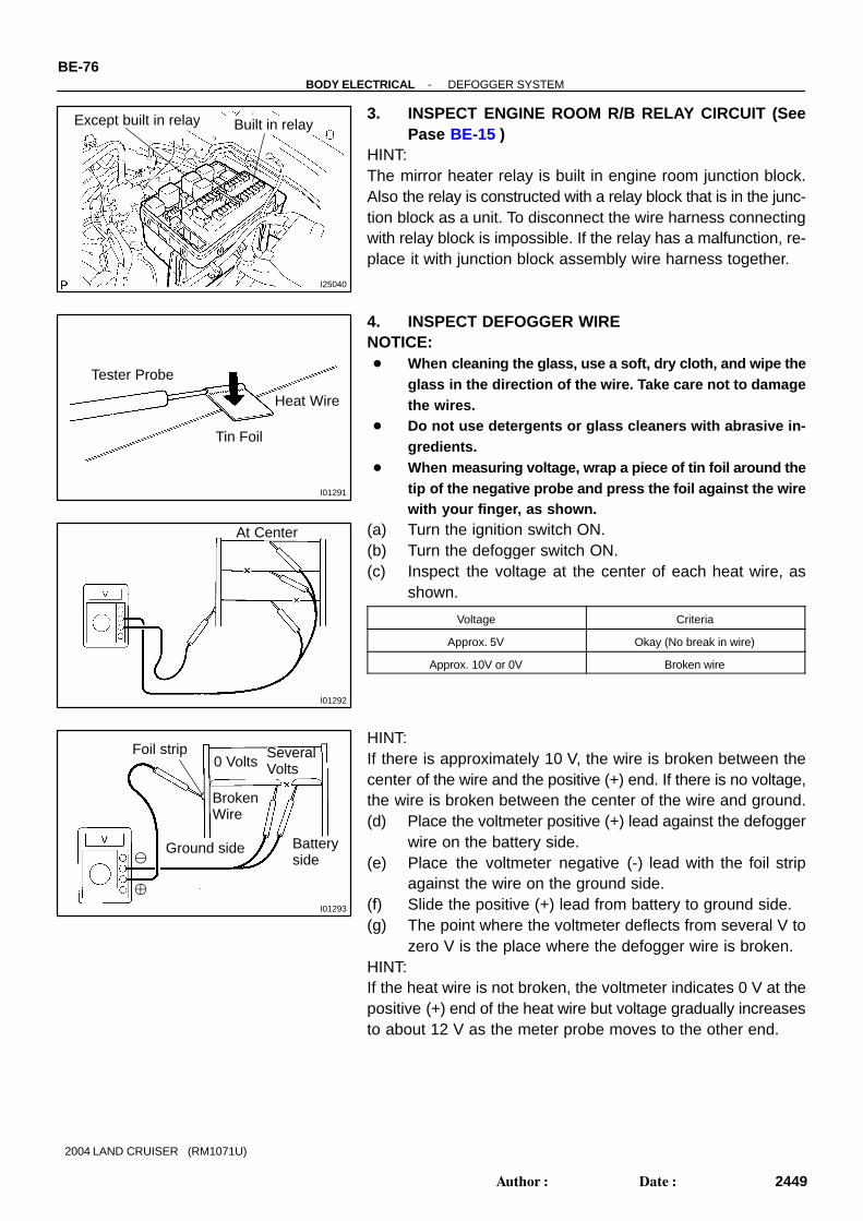
I25040
Built in relayExcept built in relay
I01291
Tester Probe
Tin Foil
Heat Wire
I01292
At Center
I01293
0 Volts
BrokenWire
SeveralVolts
Batteryside
Ground side
Foil strip
BE-76-BODY ELECTRICAL DEFOGGER SYSTEM
2449Author: Date:
2004 LAND CRUISER (RM1071U)
3. INSPECT ENGINE ROOM R/B RELAY CIRCUIT (SeePase BE-15 )
HINT:The mirror heater relay is built in engine room junction block.Also the relay is constructed with a relay block that is in the junc-tion block as a unit. To disconnect the wire harness connectingwith relay block is impossible. If the relay has a malfunction, re-place it with junction block assembly wire harness together.
4. INSPECT DEFOGGER WIRENOTICE: When cleaning the glass, use a soft, dry cloth, and wipe the
glass in the direction of the wire. Take care not to damagethe wires.
Do not use detergents or glass cleaners with abrasive in-gredients.
When measuring voltage, wrap a piece of tin foil around thetip of the negative probe and press the foil against the wirewith your finger, as shown.
(a) Turn the ignition switch ON.(b) Turn the defogger switch ON.(c) Inspect the voltage at the center of each heat wire, as
shown.
Voltage Criteria
Approx. 5V Okay (No break in wire)
Approx. 10V or 0V Broken wire
HINT:If there is approximately 10 V, the wire is broken between thecenter of the wire and the positive (+) end. If there is no voltage,the wire is broken between the center of the wire and ground.(d) Place the voltmeter positive (+) lead against the defogger
wire on the battery side.(e) Place the voltmeter negative (-) lead with the foil strip
against the wire on the ground side.(f) Slide the positive (+) lead from battery to ground side.(g) The point where the voltmeter deflects from several V to
zero V is the place where the defogger wire is broken.HINT:If the heat wire is not broken, the voltmeter indicates 0 V at thepositive (+) end of the heat wire but voltage gradually increasesto about 12 V as the meter probe moves to the other end.

I01294
Repair Point
BrokenWire
Marking Tape
I01295
I25799
5
12
-BODY ELECTRICAL DEFOGGER SYSTEMBE-77
2450Author: Date:
2004 LAND CRUISER (RM1071U)
5. IF NECESSARY, REPAIR DEFOGGER WIRE(a) Clean the broken wire tips with grease, wax and silicone
remover.(b) Place the masking tape along both sides of the wire for
repair.(c) Thoroughly mix the repair agent (Dupont paste No.
4817).
(d) Using a fine tip brush, apply a small amount of the agentto the wire.
(e) After a few minutes, remove the masking tape.(f) Do not repair the defogger wire for at least 24 hours.
6. w/ Mirror heater:INSPECT MIRROR HEATER OPERATION
(a) Connect the positive (+) lead from the battery to terminal5 and the negative (-) lead to terminal 12.
(b) Check that the mirror becomes warm.HINT:It will take a short time for the mirror to become warm.

BE0GS-19
I24745
Mirror Assenbly Mirror Heater
Rear Window Defogger
Cowl Side J/B LH DEFOG Fuse DEFOG Relay
Ignition Switch
Integration Control Panel Assembly Defogger Switch Mirror Heater Switch
Engine Room R/B MIR HTR Fuse MIR HTR Relay
BE-74-BODY ELECTRICAL DEFOGGER SYSTEM
2447Author: Date:
2004 LAND CRUISER (RM1071U)
DEFOGGER SYSTEMLOCATION

BE0G8-06
I04266
12
BE-196-BODY ELECTRICAL ENGINE IMMOBILISER SYSTEM
2569Author: Date:
2004 LAND CRUISER (RM1071U)
INSPECTIONINSPECTION TRANSPONDER KEY COIL CONTINUITYCheck that continuity exists between terminals 1 and 2.If continuity is not as specified, replace the coil.

BE02Q-23
I25526I06215
ECM
Transponder Key Coil
Engine Room R/B EFI Fuse EFI and ECD Relay
DLC3
Transponder Key Amplifier
Passenger Side Junction Block IGN Fuse
-BODY ELECTRICAL ENGINE IMMOBILISER SYSTEMBE-195
2568Author: Date:
2004 LAND CRUISER (RM1071U)
LOCATION

BE1Z6-03
START
Insert the key in the key cylinder.
Under registration
Registration completion
Remove the key.
Will you register thenext key?
No
Security indicator blinks until the first
key is inserted. The indicator comes
on after the key registration.
Security IndicatorOFF
END
Yes
Security Indicator ON (After the last key (sub-key) isregistered, the indicator re-mains OFF until removing thekey. And after removing the key,the indicator blinks.)
-BODY ELECTRICAL ENGINE IMMOBILISER SYSTEMBE-191
2564Author: Date:
2004 LAND CRUISER (RM1071U)
ENGINE IMMOBILISER SYSTEMREGISTRATION PROCEDURE1. KEY REGISTRATION IN AUTOMATIC REGISTRATION MODE(a) Registration of a new transponder key.HINT: This must be done when you install a new Transponder key ECU. The new Transponder key ECU is on the automatic key code registration mode. The already fixed of
key codes for this Transponder key ECU can be registered.On this type of vehicle, up to 4 key codes can be registered.
A master and sub key are registered automatically.
HINT: When a key is not inserted in the key cylinder on the automatic registration mode, the security indicator
always comes. When the immobiliser system operates normally and the key is pulled out, the security indicator blinks.
(b) Automatic registration mode completionIf completing the mode forcibly when registering more than 1 key code on the automatic registrationmode, perform the following procedures.

1.8 Sec.
0.2 Sec. 0.25 Sec. 0.5 Sec.
0.25 Sec. 1 Sec.
Blinks Code 2-1 Code2-2
0.25 Sec.
0.25 Sec.0.5 Sec.
1 Sec.
Code2-3
0.25 Sec.
0.25 Sec.0.5 Sec.
1 Sec.
BE-192-BODY ELECTRICAL ENGINE IMMOBILISER SYSTEM
2565Author: Date:
2004 LAND CRUISER (RM1071U)
After registering 1 more key code with master key, perform step (1) or (2) without pulling the key outor inserting the already registered key.(1) Turn the ignition switch LOCK → ON 5 times within 10 sec.(2) With the hand-held tester, require automatic registration mode completion.
2. REGISTRATION OF ADDITIONAL MASTER KEY AND SUB KEYIt is possible to carry out additional registration of the supply key.HINT: It is possible to register up to 5 master key codes including the already registered key code. It is possible to register up to 3 sub key codes including the already registered key code. When any operation period described below is over, registration mode cannot be completed. When the next procedure is performed while the previous timer is working, the timer stops counting
time, and then the next timer starts. When replacing ”Ignition Cylinder Key Set” or ”Lock Cylinder Set”, perform registration following the
procedure using the original master key. However, after the registration of the additional master key,as the original master key and the original sub-key is not necessary any more, erase registration ofthose key codes.
For the registration order, it is not necessary to distinguish between Main and Sub.(Main key and Sub key are automatically identified)
When a registration error in the transponder key ECU is detected, the security indicator indicates the follow-ing codes.
2 - 1Communication error between the key to be registered and the transponder key
ECU
2 - 2 When trying to register the key that is already registered
2 - 3When exceeding the number of keys which can be registered (Master key: 5, Sub
key: 3)

Security indicator OFF
Within 10 secs.
START
Insert already registered master key in the key cylinder and turnthe ignition switch ON.
Using hand-held tester, select key registration.
Remove the master key.
Insert a key to be registered in key cylinder.
Keep ignition switch at ON position for 60 seconds or more.
Remove the key.
END
Security indicator ON
Security indicator blinks
Security indicator blinks
Security indicator blinks
HINT:Follow the screen of the hand-held tester for detailed procedure.
Within 120 secs.
Within 20 secs.
Security indicator blinks
Security indicator OFF
-BODY ELECTRICAL ENGINE IMMOBILISER SYSTEMBE-193
2566Author: Date:
2004 LAND CRUISER (RM1071U)
Using hand-held tester:

Within 10 secs.
START
Insert already registered master key in the key cylinder and turnthe ignition switch ON.
Using hand-held tester, select key erasion.
Remove the master key.
END
Security indicator ON about 1 sec. and OFF
Security indicator blinks
Security indicator blinks
Security indicator ON
HINT:
Follow the screen of the hand-held tester for more detailed procedure.
(Key code erased)
BE-194-BODY ELECTRICAL ENGINE IMMOBILISER SYSTEM
2567Author: Date:
2004 LAND CRUISER (RM1071U)
3. ERASURE OF TRANSPONDER KEY CODE
Using hand-held tester:

BE0RU-04
I25046
A-bolt
BE-38-BODY ELECTRICAL FOG LIGHT SYSTEM
2411Author: Date:
2004 LAND CRUISER (RM1071U)
ADJUSTMENTADJUST FOGLIGHT AIMA-bolt : Vertical Direction

BE0RT-04
I06374
ON
OFF
I25040
Built in relayExcept built in relay
-BODY ELECTRICAL FOG LIGHT SYSTEMBE-37
2410Author: Date:
2004 LAND CRUISER (RM1071U)
INSPECTION1. INSPECT FOG LIGHT SWITCH CONTINUITY
Switch position Tester connection Specified condition
OFF - No continuity
ON 10 - 11 Continuity
If continuity is not as specified, replace the switch.
2. INSPECT ENGINE ROOM R/B RELAY CIRCUIT(SeePase BE-15 )
HINT:The foglight relay is built in engine room junction block. Also therelay is constructed with a relay block that is in the junction blockas a unit. To disconnect the wire harness connecting with relayblock is impossible. If the relay has a malfunction, replace it withjunction block assembly wire harness together.

BE0H2-16
I24736
Front Fog Light
Combination Switch Front Fog Light Switch
Engine Room R/B FR FOG Relay FR FOG Fuse
BE-36-BODY ELECTRICAL FOG LIGHT SYSTEM
2409Author: Date:
2004 LAND CRUISER (RM1071U)
FOG LIGHT SYSTEMLOCATION

I25809
BE2F0-01
I25810
I25811
BE-190-BODY ELECTRICAL GARAGE DOOR OPENER SYSTEM
2563Author: Date:
2004 LAND CRUISER (RM1071U)
INSPECTION1. INSPECT GARAGE DOOR OPENER SWITCHPress the switch and check that each LED (red) lights up.Even if only one switch is found not to light up, replace it.
2. INSPECT GARAGE DOOR OPENER REGISTRATIONAND TRANSMITTING
HINT:Use the home link tester made by KENT MORE for this test.As it is necessary to record the code of the hand held transmit-ter, customer’s code will be erased. When the inspection com-pletes, please register the customer’s again.(a) Check that the code of hand held transmitter for inspec-
tion can be recorded (See page BE-186 ).If the code can not be registered, replace garage door opener.
(b) Press the switch which an inspection code has been reg-istered for and check that LED (green) of the home linktester lights up.
If the LED (green) does not light up, replace the garage dooropener.

BE0TZ-06
I25525
Grage Door Opener Switch
Cowl Side J/B RH DOME Fuse
-BODY ELECTRICAL GARAGE DOOR OPENER SYSTEMBE-189
2562Author: Date:
2004 LAND CRUISER (RM1071U)
LOCATION

BE0TY-04
I25812
BE-186-BODY ELECTRICAL GARAGE DOOR OPENER SYSTEM
2559Author: Date:
2004 LAND CRUISER (RM1071U)
GARAGE DOOR OPENER SYSTEMREGISTRATION PROCEDURE1. NEW CODE REGISTRATIONNOTICE: If pressing the switch of the original transmitter to
register the code, the system might operate. When registering the transmitter codes such as for
garage or gate, check that there is nobody aroundthose places then register.
(a) Press the switch for the item to be registered for 20 se-conds
HINT:When transferring to registration mode, LED (red) blinks in 1 Hzcycle.
(b) In the condition of (a), bring the original transmitter to with-in 1-inch area around the garage door opener and pressthe switch. (code transmitting).
HINT:When code registration completes correctly, LED (red) blinks in5.6 Hz cycle.

I03487
GARAGE DOOR OPENER SWITCH
LEARN MODE
LEDOPERATION
ORIGINAL TRANSMITTER
PRESSED
ENTER
EXIT
ON
OFF
20 sec
LED flashesat a rate of 1 Hz
LED flashes at arate of 5.6 Hz
PRESSED
ON
OFF
-BODY ELECTRICAL GARAGE DOOR OPENER SYSTEMBE-187
2560Author: Date:
2004 LAND CRUISER (RM1071U)
New code registration timing chart
If a code can not be registered, observe the following condi-tions.HINT: If the battery of original transmitter is consumed. Press the switch of the transmitter repeatedly in registra-
tion mode, as some transmitters stop transmitting for 1 to2 seconds.
This system is not applicable to the garage door openerwhich had been made before 1982.
2. CODE DELETION(a) Press the switches at both ends of garage door opener
simultaneously for 20 seconds.HINT:When transferring to deletion mode, LED (red) blinks in 6 Hzcycle.(b) When releasing the switch within 10 seconds after trans-
ferring to deletion mode, all the registered codes will beerased.
HINT:Press the switch until blinking in 6 Hz cycle stops, so that thedefault code for check is set.

I03488
LEDOPERATION
GARAGE DOOROPENER SWITCH(Switch at either end)
ON
OFF
CLEAR/DEFAULT MODE
PRESSED
LOAD DEFAULT
LED flashes at a rate of 6 HZ
10 SEC20 SEC
PRESSED
ON
OFF
Enter in erase mode to erase all 3 channels
BE-188-BODY ELECTRICAL GARAGE DOOR OPENER SYSTEM
2561Author: Date:
2004 LAND CRUISER (RM1071U)
Code deletion timing chart

BE0RS-03
I06379
Adjusting Bolt A (Vertical Direction)
BE-34-BODY ELECTRICAL HEADLIGHT AND TAILLIGHT SYSTEM
2407Author: Date:
2004 LAND CRUISER (RM1071U)
ADJUSTMENT

I20844
0.4 °
3 m (9.84 ft)
H20.9 mm (0.823 in.)
7
V RH Line
90 °
V LH Line
4
V LH Line V Line V RH Line6 5 6
V LH Line V Line V RH Line6 5 6
H4
O: step No.
7
H 4
20.9 mm (0.823 in.)1,146mm (45.1 in.)
Low Beam:
High Beam:
20.9 mm (0.823 in.)
20.9 mm (0.823 in.)
1,146mm (45.1 in.)
1,146mm (45.1 in.)
H RH and H LH lines
High BeamLow Beam
-BODY ELECTRICAL HEADLIGHT AND TAILLIGHT SYSTEMBE-35
2408Author: Date:
2004 LAND CRUISER (RM1071U)
ADJUST HEADLIGHT AIM ONLY(a) Place the vehicle in the following conditions.
The area around the headlight is not deformed. The vehicle is parked on a level surface. Tire inflation pressure is the specified value. A driver is in the driver’s seat and the vehicle is in a state ready for driving (with a tank full). The vehicle has been bounced several times.
(b) Check the headlight aiming.(1) Prepare a thick white paper.(2) Stand the paper perpendicular to the ground at the position 9.84 ft away from the headlights.(3) Ensure that the center line of the vehicle and the paper face forms a 90-degree angle as shown
in the illustration.(4) Draw a horizontal line (H line) on the paper, showing where the headlights should strike.(5) Draw a vertical line (V line) to where the center line of the vehicle is to be.(6) Draw 2 vertical lines (by connecting the low and high beam center marks) to where the both head-
lights should strike (V RH and V LH lines).(7) Draw a horizontal line (by connecting the both low beam center marks) to where the headlights
should strike (H RH and H LH lines).HINT:The H RH and H LH line is 0.4° below the horizontal line (H line) of the light axis.
(8) Start the engine.(9) Turn the headlights ON.(10) Check that the headlights properly strike the position shown in the illustration.(11) If not, adjust the lights in the vertical direction.
HINT:As shown in the illustration, adjust each aim of the RH and LH lights.(c) When adjusting it in the vertical direction:
Using adjusting bolt A, adjust the headlight aim to within the specified range.

BE0H9-08
I25531
Switch Body
Wiper and Washer Switch
Light Control Switch andHeadlight Dimmer Switch
Spiral Cable
Tilt and Telescopic Switch
-BODY ELECTRICAL HEADLIGHT AND TAILLIGHT SYSTEMBE-31
2404Author: Date:
2004 LAND CRUISER (RM1071U)
COMPONENTS
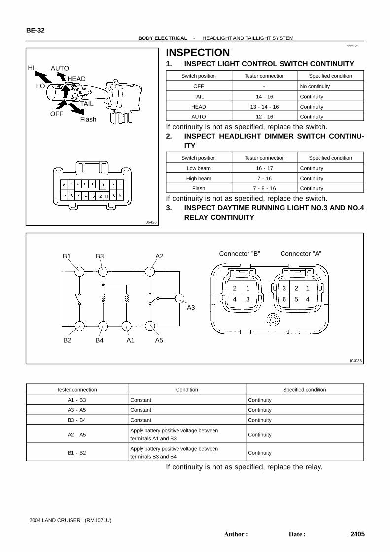
I06426
HI
FlashOFF
TAIL
HEAD
AUTO
LO
BE2EH-01
I04036
12
34
123
456
Connector ”B” Connector ”A”A2B3B1
A3
A5A1B4B2
BE-32-BODY ELECTRICAL HEADLIGHT AND TAILLIGHT SYSTEM
2405Author: Date:
2004 LAND CRUISER (RM1071U)
INSPECTION1. INSPECT LIGHT CONTROL SWITCH CONTINUITY
Switch position Tester connection Specified condition
OFF - No continuity
TAIL 14 - 16 Continuity
HEAD 13 - 14 - 16 Continuity
AUTO 12 - 16 Continuity
If continuity is not as specified, replace the switch.2. INSPECT HEADLIGHT DIMMER SWITCH CONTINU-
ITY
Switch position Tester connection Specified condition
Low beam 16 - 17 Continuity
High beam 7 - 16 Continuity
Flash 7 - 8 - 16 Continuity
If continuity is not as specified, replace the switch.3. INSPECT DAYTIME RUNNING LIGHT NO.3 AND NO.4
RELAY CONTINUITY
Tester connection Condition Specified condition
A1 - B3 Constant Continuity
A3 - A5 Constant Continuity
B3 - B4 Constant Continuity
A2 - A5Apply battery positive voltage between
terminals A1 and B3.Continuity
B1 - B2Apply battery positive voltage between
terminals B3 and B4.Continuity
If continuity is not as specified, replace the relay.

I25040
Built in relayExcept built in relay
I22144
Wire Harness Side:
1 2
3 4
5 6
I22145
From Back Side:
123456
-BODY ELECTRICAL HEADLIGHT AND TAILLIGHT SYSTEMBE-33
2406Author: Date:
2004 LAND CRUISER (RM1071U)
4. INSPECT ENGINE ROOM R/B RELAY CIRCUIT (SeePase BE-15 )
HINT:The (Headlight, DIM, Tail relay) is built in engine room junctionblock. Also the relay is constructed with a relay block that is inthe junction block as a unit. To disconnect the wire harness con-necting with relay block is impossible. If the relay has a malfunc-tion, replace it with junction block assembly wire harness to-gether.
5. Connector disconnected:INSPECT AUTOMATIC LIGHT CONTROL SENSORCIRCUIT
Disconnect the connector from the sensor and inspect the con-nector on the wire harness side, as shown in the chart.HINT: Ignition switch is ON. Light control switch is in AUTO. Vehicle’s surroundings are bright.
Tester connection Condition Specified condition
6 - Ground Constant Continuity
3 - GroundClose the driver’s door again while the ignition
switch OFFNo voltage
3 - Ground Ignition switch position ON 5.2 - 9.0V
If circuit is as specified, perform the inspection on the followingpage.If the circuits is not as specified, inspect the circuit connectedto other parts.
6. Connector disconnected:INSPECT AUTOMATIC LIGHT CONTROL SENSORCIRCUIT
Connect the wire harness side connector to the sensor and in-spect wire harness side connector from the back side, asshown.HINT: Ignition switch is ON. Light control switch is in AUTO. Vehicle’s surroundings are bright.
Tester connection Condition Specified condition
4 - Ground
(CLTS - Body ground)Constant Pulse generation
3 - Ground
(CLTB - Body ground)Ignition switch ON 10 - 14V
If the circuits is not as specified, try replacing the sensor with anew one.

BE0H8-11
I24735
Cowl Side J/B LH Body ECU ECU-IG1 Fuse ECU-B1 Fuse
Combination Switch Light Control Switch Headlight Dimmer Switch
Ignition Switch
Headlight
Engine Room R/B HEAD LH-UPR Fuse HEAD RH-UPR Fuse HEAD LH-LWR Fuse HEAD RH LWR Fuse HEAD Relay HEAD HI Relay TAIL Fuse TAIL Relay
Automatic Light Control Sensor
Taillight
Daytime Running Light No.3 and No.4 Relay
BE-30-BODY ELECTRICAL HEADLIGHT AND TAILLIGHT SYSTEM
2403Author: Date:
2004 LAND CRUISER (RM1071U)
HEADLIGHT AND TAILLIGHT SYSTEMLOCATION

BE0FZ-19
I24653
I24654
6
I04197
BE-198-BODY ELECTRICAL HORN SYSTEM
2571Author: Date:
2004 LAND CRUISER (RM1071U)
INSPECTION1. INSPECT HORN SWITCH(a) Disconnect the negative (-) terminal from the battery.(b) Remove the left and right covers from the steering wheel.(c) Using a torx socket wrench, loosen the 2 bolts.(d) Pull up the horn pad and place it on the steering column,
as shown.HINT:Do not disconnect the connector from the horn pad.(e) Disconnect the connector from the slip ring.
(f) Check that no continuity exists between terminal 6 of theconnector and body ground.
(g) Check that continuity exists between terminal 6 of theconnector and body ground when the horn contact plateis pressed against the steering spoke assembly.
If continuity is not as specified, repair or replace the steeringwheel or wire harness as necessary.(h) Install the horn pad in place and using a torx socket
wrench, torque the 2 bolts.Torque: 7.1 N·m (72 kgf·cm, 62 in.·lbf)
(i) Install the left and right covers.(j) Connect the negative (-) terminal to the battery.
2. INSPECT HORN OPERATIONConnect the positive (+) lead from the battery to the terminaland negative (-) lead to the horn body and check that the hornblows.If operation is not as specified, replace the horn.

I25040
Built in relayExcept built in relay
-BODY ELECTRICAL HORN SYSTEMBE-199
2572Author: Date:
2004 LAND CRUISER (RM1071U)
3. INSPECT ENGINE ROOM R/B RELAY CIRCUIT (SeePase BE-15 )
HINT:The horn relay is built in engine room junction block. Also therelay is constructed with a relay block that is in the junction blockas a unit. To disconnect the wire harness connecting with relayblock is impossible. If the relay has a malfunction, replace it withjunction block assembly wire harness together.

BE0FY-27
I25527
Horn
Engine Room R/B HORN Fuse HORN Relay
Horn Switch
-BODY ELECTRICAL HORN SYSTEMBE-197
2570Author: Date:
2004 LAND CRUISER (RM1071U)
HORN SYSTEMLOCATION

BE2EG-01
I25786
123
I25795
123
I25795
N01731
2
N01732
2
1
BE-44-BODY ELECTRICAL INTERIOR LIGHT SYSTEM
2417Author: Date:
2004 LAND CRUISER (RM1071U)
INSPECTION1. INSPECT FRONT PERSONAL LIGHT SWITCH CONTI-
NUITY
Switch position Tester connection Specified condition
OFF - No continuity
ON 1 - 2 Continuity
If continuity is not as specified, replace the light assembly orbulb.
2. INSPECT REAR PERSONAL LIGHT SWITCH CONTI-NUITY
Switch position Tester connection Specified condition
OFF - No continuity
ON 1 - 3 Continuity
If continuity is not as specified, replace the light assembly orbulb.
3. INSPECT ROOM LIGHT SWITCH CONTINUITY
Switch position Tester connection Specified condition
Room Light Switch OFF - No continuity
Room Light Switch DOOR 2 - 3 Continuity
Room Light Switch ON 1 - 3 Continuity
If continuity is not as specified, replace the light assembly orbulb.
4. INSPECT REAR ROOM LIGHT SWITCH CONTINUITY(a) Disconnect the connector from room light assembly.(b) Turn the room light switch ON, check that continuity exists
between terminal 2 and body ground.
(c) Turn the room light switch DOOR, check that continuityexists between terminal 1 and 2.
If operation is not as specified, replace the light assembly orbulb.

I04050
2 1
OFF
ON
I06423
ON
OFF
I06431e-2-2-J
I06432
Back Door Lock Assembly Back Door Courtesy Switch
I06433
ON
OFF
12
-BODY ELECTRICAL INTERIOR LIGHT SYSTEMBE-45
2418Author: Date:
2004 LAND CRUISER (RM1071U)
5. INSPECT VANITY LIGHT CONTINUITY
Switch position Tester connection Specified condition
OFF (closed) - No continuity
ON (opened) 1 - 2 Continuity
If continuity is not as specified, replace the vanity light assemblyor bulb.
6. INSPECT DOOR COURTESY SWITCH CONTINUITY(a) Check that continuity exists between terminal and switch
body with the switch ON (switch pin released).(b) Check that no continuity exists between terminal and
switch body with the switch OFF (switch pin pushed).If continuity is not as specified, replace the switch.
7. INSPECT DOOR COURTESY LIGHT CONTINUITYUsing an ohmmeter, check that continuity exists between termi-nals.If continuity is not as specified, replace the light assembly orbulb.
8. INSPECT BACK DOOR COURTESY SWITCH CONTI-NUITY
Switch position Tester connection Specified condition
OFF (closed) - No continuity
ON (opened) 1 - 2 Continuity
If continuity is not as specified, replace the back door lock as-sembly.
9. INSPECT GLOVE COMPARTMENT DOOR COURTE-SY SWITCH CONTINUITY
Switch position Tester connection Specified condition
OFF (closed) - No continuity
ON (opened) 1 - 2 Continuity
If continuity is not as specified, replace the switch.

I06434e-2-2-J
BE-46-BODY ELECTRICAL INTERIOR LIGHT SYSTEM
2419Author: Date:
2004 LAND CRUISER (RM1071U)
10. INSPECT LICENCE PLATE LIGHT CONTINUITYUsing an ohmmeter, check that continuity exists between termi-nals.If continuity is not as specified, replace the light assembly orbulb.

BE0RW-03
I24738
Licence Plate Light
Door Courtesy Switch Back Door Lock Assmbly Back Door Courtesy Switch
Rheostat Light Control
Glove CompartmentDoor Courtesy Switch
Cowl Side J/B LH DOME Relay
Door Courtesy Switch
Cowl Side J/B RH DOME Fuse
BE-42-BODY ELECTRICAL INTERIOR LIGHT SYSTEM
2415Author: Date:
2004 LAND CRUISER (RM1071U)
INTERIOR LIGHT SYSTEMLOCATION

I24739
Vanity Light
Front Personal Light
Room Light andRear Personal Light
Door Courtesy Light
Rear Room Light
-BODY ELECTRICAL INTERIOR LIGHT SYSTEMBE-43
2416Author: Date:
2004 LAND CRUISER (RM1071U)
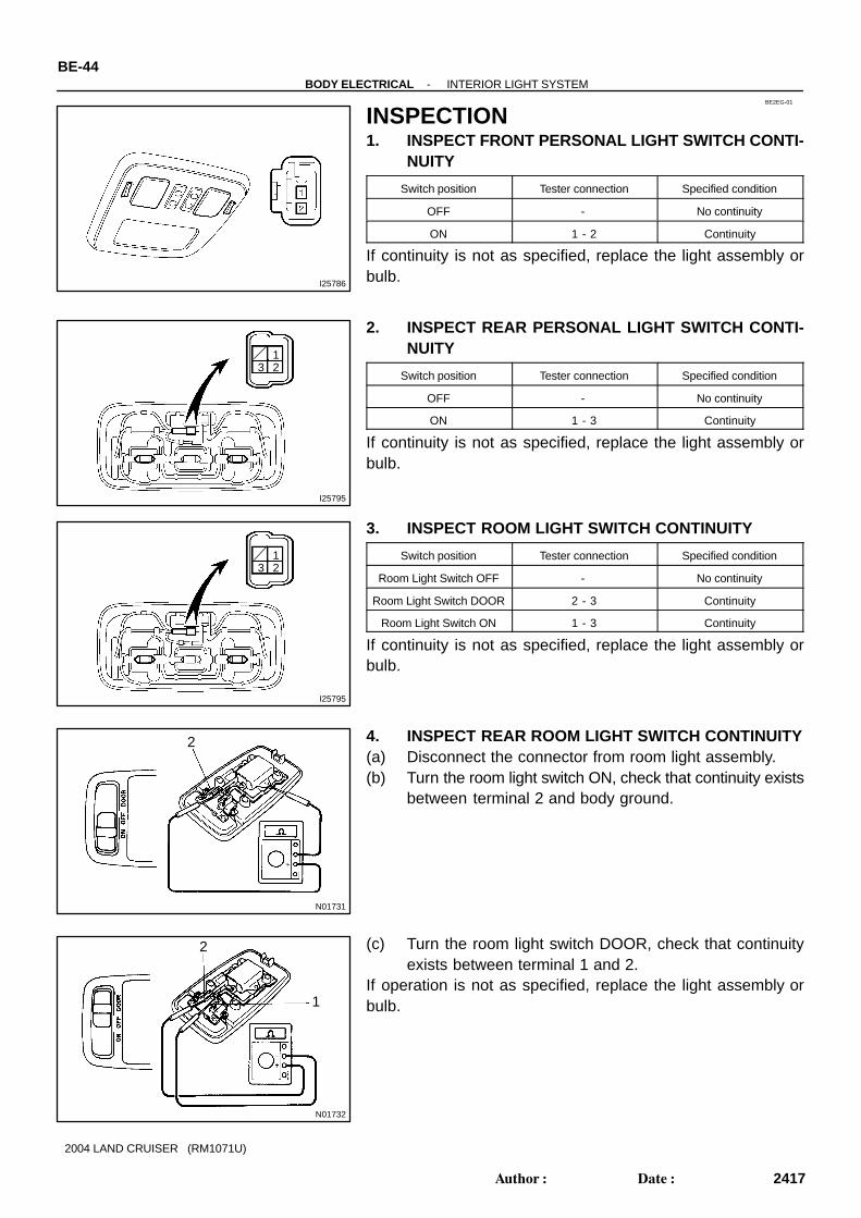

BE0RO-03
I01256
12345678
LOCK
ACCON
START
I06372
N20125
12
OFF
ON
-BODY ELECTRICAL IGNITION SWITCH AND KEY UNLOCK WARNING SWITCH
BE-29
2402Author: Date:
2004 LAND CRUISER (RM1071U)
INSPECTION1. INSPECT IGNITION SWITCH CONTINUITY
Switch position Tester connection Specified condition
LOCK - No continuity
ACC 2 - 3 Continuity
ON2 - 3 - 4
6 - 7Continuity
START1 - 2 - 4
6 - 7 - 8Continuity
If continuity is not as specified, replace the switch.
2. INSPECT IGNITION KEY ILLUMINATION OPERATIONConnect the positive (+) lead from the battery to terminal 1 andthe negative (-) lead to terminal 2, and check that the indicatorlight lights up.If operation is not as specified, replace the switch.
3. INSPECT KEY UNLOCK WARNING SWITCH CONTI-NUITY
Switch position Tester connection Specified condition
OFF (Key removed) - No continuity
ON (Key set) 1 - 2 Continuity
If continuity is not as specified, replace the switch.Connect the switch connector and inspect the connector onwire harness side from the back side, as shown.

BE01L-17
I24734
Ignition Switch
Key Unlock Warning SwitchCowl Side J/B LH
BE-28 -BODY ELECTRICAL IGNITION SWITCH AND KEY UNLOCK WARNING SWITCH
2401Author: Date:
2004 LAND CRUISER (RM1071U)
IGNITION SWITCH AND KEY UNLOCK WARNING SWITCHLOCATION

BE2E1-01
1 MULTI DISPLAY DOES NOT OPERATE
I25794
10
9
14
16
8
ACC Fuse
ECU-B1 Fuse
Body Control ECUand TransponderECU
A/C Contlor Assy
Ground
ACC
+B
SECURITY
A/C TEMP
GND
Multi Display Assembly
11ECU-IG FuseIG
1
2
3
UART+
UART-
TC
Combination Meter
Body Control ECU
Combination Meter
BE-178-BODY ELECTRICAL MULTI DISPLAY
2551Author: Date:
2004 LAND CRUISER (RM1071U)
MULTI DISPLAYTROUBLESHOOTINGHINT: Troubleshoot the Multi Display according to the table below. w/ Navigation System (See PageDI-1 151)
Troubleshooting No.
Multi disolay does not operate. 1
Clock loses or gains time. 2
Drive monitor function malfunction. 3
Outer temperature display malfunction. 4
Security indicator does not light up. (See page DI-953 )
± 1.5 seconds / day
1. TROUBLESHOOTING NO.1
(a) Check that the battery positive voltage is 10 - 16 V.If voltage is not as specified, replace the battery.(b) Check that the ECU-IG, ECU-B and ACC fuses are not
blown.If the fuse is blown, replace the fuse and check for short.(c) Troubleshoot the multi display as follows.HINT:Inspect the connector on the wire harness side.

Yes
Yes
No
No
Is there battery positive voltage between terminal IG andbody ground?
Is there battery positive voltage between terminal +B andbody ground?
Replace multi display.
IG wire harness faulty.
Yes
NoIs there battery positive voltage between terminal GND andbody ground? Ground wire harness faulty.
+B wire harness faulty.
Yes
NoIs there battery positive voltage between terminal ACC andbody ground? ACC wire harness faulty.
2 CLOCK LOSES OR GAINS TIME
Yes
Is there battery positive voltage between terminal +B andbody ground?
Adjust clock or replace multi display.
Bellow 10 V Locate cause and repair, or recharge battery.
Yes
Is there battery positive voltage between terminal ACC andbody ground?
Bellow 10 V Locate cause and repair, or recharge battery.
-BODY ELECTRICAL MULTI DISPLAYBE-179
2552Author: Date:
2004 LAND CRUISER (RM1071U)
2. TROUBLESHOOTING NO.2
(a) Check that the battery positive voltage is 10 - 16 V.If voltage is not as specified, replace the battery.(b) Inspect the error of the clock.
Allowable error (per day): ± 1.5 secondsIf the error exceeds the allowable error, replace the multi display.(c) Check that the clock adjusting button is sticking in position and has failed to return.If the error exceeds the allowable error, replace the multi display.(d) Troubleshoot the clock as follows.HINT:Inspect the connector on the wire harness side.

3 DRIVE MONITOR FUNCTION MALFUNCTION
Yes
Does cotinuity exists waire harness between combination meter andmulti display?
Replace multi display.
No Repair or replace wire harness.
Yes
Is combination meter operation normaly?Go to Combination MeterNo
4 OUTER TEMPERATURE DISPLAY MALFUNCTION
Yes
Does cotinuity exists waire harness between A/C control Assy andmulti display?
Replace multi display.
No Repair or replace wire harness.
Yes
Is A/C operation normaly?Go to Air Conditioner SystemNo
BE-180-BODY ELECTRICAL MULTI DISPLAY
2553Author: Date:
2004 LAND CRUISER (RM1071U)
3. TROUBLESHOOTING NO.3
(a) Check that the battery positive voltage is 10 - 16 V.If voltage is not as specified, replace the battery.(b) Troubleshoot the drive monitor function as follows.HINT:Inspect the connector on the wire harness side.
4. TROUBLESHOOTING NO.4
(a) Check that the battery positive voltage is 10 - 16 V.If voltage is not as specified, replace the battery.(b) Troubleshoot the outer temperature display as follows.HINT:Inspect the connector on the wire harness side.
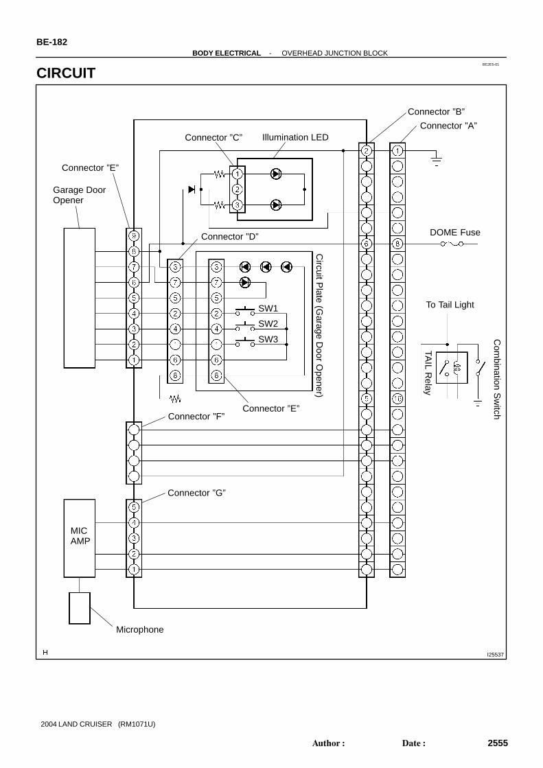
BE2E5-01
I25537
Connector ”A”
Connector ”B”
To Tail Light
Microphone
Connector ”D”
Garage Door Opener
Connector ”C” Illumination LED
DOME Fuse
Com
bination Sw
itch
TAIL R
elay
Connector ”E”
SW1
SW2
SW3
Circuit P
late (Garage D
oor Opener)
Connector ”E”Connector ”F”
Connector ”G”
MICAMP
BE-182-BODY ELECTRICAL OVERHEAD JUNCTION BLOCK
2555Author: Date:
2004 LAND CRUISER (RM1071U)
CIRCUIT

BE2E6-01
I24661
Main Circuit Plate
Circuit Plate (Garage Door Opener Switch)
-BODY ELECTRICAL OVERHEAD JUNCTION BLOCKBE-183
2556Author: Date:
2004 LAND CRUISER (RM1071U)
COMPONENTS

I24662
12
34
A
Circuit Plate(Garage Door Opener Switch)
Main Circuit Plate
C
B
G
E
D
BE-184-BODY ELECTRICAL OVERHEAD JUNCTION BLOCK
2557Author: Date:
2004 LAND CRUISER (RM1071U)
Parts No. Connector name Related to systems
A, B Vehicle wire harness connector -
C Overhead console illumination connector (Unbar) Overhead junction block illumination
D Garage door opener ECU connector Garage door opener system
E Garage door opener ECU connector Garage door opener system
G Voice recognition connector Navigation system
1 Garage door opener substrate flat harness connector Garage door opener system
2 Garage door opener switch Garage door opener system
3 Garage door opener LED (Green) Garage door opener system
4 Garage door opener operate indicator LED (Red) Garage door opener system

I20746
Wire Harness Side:
BE2E7-01
I24663
-BODY ELECTRICAL OVERHEAD JUNCTION BLOCKBE-185
2558Author: Date:
2004 LAND CRUISER (RM1071U)
INSPECTION1. INSPECT OVERHEAD JUNCTION BLOCK ASSEMBLYDisconnect the connector from the overhead J/B and inspectthe connector on the wire harness side, as shown.
Tester connection Condition Specified condition
1 - Ground Constant Continuity
8 - Ground Constant Battery positive voltage
11 - Ground Ignition switch OFF or ACC No voltage11 Ground
Ignition switch ON Battery positive voltage
If continuity is not as specified, repair or replace the wire har-ness.
2. Overhead J/B side:INSPECT OVERHEAD JUNCTION BLOCK ASSEMBLY
Circuit name Tester connection Specified condition
Power source circuit A8 - B6 - E6 Continuity
Ground circuit A1 - B2 - E8 - D3 Continuity
Microphone circuit B10 - G4 Continuity
Microphone circuit B9 - G2 Continuity
If continuity is not as specified, replace the overhead J/B as-sembly.

BE2E4-01
I25538
Cowl Side J/B RH SECURITY Fuse
Overhead Junction Block Sliding Roof Switch Garage Door Opener Switch
-BODY ELECTRICAL OVERHEAD JUNCTION BLOCKBE-181
2554Author: Date:
2004 LAND CRUISER (RM1071U)
OVERHEAD JUNCTION BLOCKLOCATION

BE2EK-01
I25784
I09912
I06229
Front door:
UNLOCK
I06228
Rear door:UNLOCK
I06227
Back door:
UNLOCK
BE-88-BODY ELECTRICAL POWER DOOR LOCK CONTROL SYSTEM
2461Author: Date:
2004 LAND CRUISER (RM1071U)
INSPECTION1. Master switch:
INSPECT DRIVER’S DOOR LOCK CONTROL SW ITCHCONTINUITY
Switch position Tester connection Specified condition
LOCK 3 - 4 Continuity
OFF - No continuity
UNLOCK 3 - 14 Continuity
If continuity is not as specified, replace the switch.2. INSPECT PASSENGER’S DOOR LOCK CONTROL
SWITCH CONTINUITY
Switch position Tester connection Specified condition
LOCK 3 - 2 Continuity
OFF - No continuity
UNLOCK 1 - 2 Continuity
If continuity is not as specified, replace the switch.
3. Front door:INSPECT DOOR UNLOCK DETECTION SWITCH CON-TINUITY
Switch position Tester connection Specified condition
OFF (Door Lock set to
LOCK)- No continuity
ON (Door Lock set to
UNLOCK)1 - 4 Continuity
If continuity is not as specified, replace the switch.
4. Rear door:INSPECT DOOR UNLOCK DETECTION SWITCH CON-TINUITY
Switch position Tester connection Specified condition
OFF (Door Lock set to
LOCK)- No continuity
ON (Door Lock set to
UNLOCK)1 - 4 Continuity
If continuity is not as specified, replace the switch.
5. Back door:INSPECT DOOR UNLOCK DETECTION SWITCH CON-TINUITY
Switch position Tester connection Specified condition
OFF (Door Lock set to
LOCK)- No continuity
ON (Door Lock set to
UNLOCK)1 - 4 Continuity
If continuity is not as specified, replace the switch.

I06225
23
UNLOCK
I06226
23
LOCK
I06223
23
UNLOCK
I06224
23LOCK
I06221
UNLOCK
23
-BODY ELECTRICAL POWER DOOR LOCK CONTROL SYSTEMBE-89
2462Author: Date:
2004 LAND CRUISER (RM1071U)
6. Front door:INSPECT DOOR LOCK MOTOR OPERATION
(a) Connect the positive (+) lead from the battery to terminal3 and the negative (-) lead to terminal 2, and check thatthe door lock link moves to UNLOCK position.
(b) Reverse the polarity and check that the door lock linkmoves to LOCK position.
If operation is not as specified, replace the door lock assembly.
7. Rear door:INSPECT DOOR LOCK MOTOR OPERATION
(a) Connect the positive (+) lead from the battery to terminal3 and the negative (-) lead to terminal 2, and check thatthe door lock link moves to UNLOCK position.
(b) Reverse the polarity and check that the door lock linkmoves to LOCK position.
If operation is not as specified, replace the door lock assembly.
8. Back door:INSPECT DOOR LOCK MOTOR OPERATION
(a) Connect the positive (+) lead from the battery to terminal3 and the negative (-) lead to terminal 2, and check thatthe door lock link moves to UNLOCK position.

I06222
23
LOCK
I06242
UNLOCK
23
I06226
23
LOCK
I06244
23
UNLOCK
I06245
23
LOCK
BE-90-BODY ELECTRICAL POWER DOOR LOCK CONTROL SYSTEM
2463Author: Date:
2004 LAND CRUISER (RM1071U)
(b) Reverse the polarity and check that the door lock linkmoves to LOCK position.
If operation is not as specified, replace the door lock assembly.
9. Front door:INSPECT PTC THERMISTOR OPERATION (Using anammeter)
(a) Connect the negative (-) lead from the battery to terminal2.
(b) Connect the positive (+) lead from the ammeter to termi-nal 3 and the negative (-) lead to battery negative (-) ter-minal, and check that the current changes from approxi-mately 3.2 A to less than 0.5 A within 20 to 70 seconds.
(c) Disconnect the leads from terminals.(d) Approximately 60 seconds later, connect the positive (+)
lead from the battery to terminal 2 and the negative (-)lead to terminal 3, and check that the door lock moves tothe LOCK position.
If operation is not as specified, replace the door lock assembly.
10. Rear door:INSPECT PTC THERMISTOR OPERATION (Using anammeter)
(a) Connect the negative (-) lead from the battery to terminal2.
(b) Connect the positive (+) lead from the ammeter to termi-nal 3 and the negative (-) lead to battery negative (-) ter-minal, and check that the current changes from approxi-mately 3.2 A to less than 0.5 A within 20 to 70 seconds.
(c) Disconnect the leads from terminals.(d) Approximately 60 seconds later, connect the positive (+)
lead from the battery to terminal 2 and the negative (-)lead to terminal 3, and check that the door lock moves tothe LOCK position.
If operation is not as specified, replace the door lock assembly.
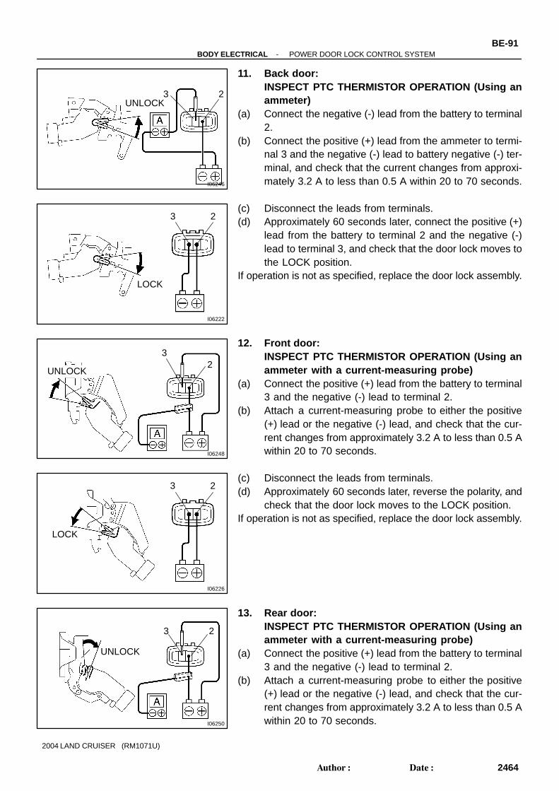
I06246
23UNLOCK
I06222
23
LOCK
I06248
23
UNLOCK
I06226
23
LOCK
I06250
23
UNLOCK
-BODY ELECTRICAL POWER DOOR LOCK CONTROL SYSTEMBE-91
2464Author: Date:
2004 LAND CRUISER (RM1071U)
11. Back door:INSPECT PTC THERMISTOR OPERATION (Using anammeter)
(a) Connect the negative (-) lead from the battery to terminal2.
(b) Connect the positive (+) lead from the ammeter to termi-nal 3 and the negative (-) lead to battery negative (-) ter-minal, and check that the current changes from approxi-mately 3.2 A to less than 0.5 A within 20 to 70 seconds.
(c) Disconnect the leads from terminals.(d) Approximately 60 seconds later, connect the positive (+)
lead from the battery to terminal 2 and the negative (-)lead to terminal 3, and check that the door lock moves tothe LOCK position.
If operation is not as specified, replace the door lock assembly.
12. Front door:INSPECT PTC THERMISTOR OPERATION (Using anammeter with a current-measuring probe)
(a) Connect the positive (+) lead from the battery to terminal3 and the negative (-) lead to terminal 2.
(b) Attach a current-measuring probe to either the positive(+) lead or the negative (-) lead, and check that the cur-rent changes from approximately 3.2 A to less than 0.5 Awithin 20 to 70 seconds.
(c) Disconnect the leads from terminals.(d) Approximately 60 seconds later, reverse the polarity, and
check that the door lock moves to the LOCK position.If operation is not as specified, replace the door lock assembly.
13. Rear door:INSPECT PTC THERMISTOR OPERATION (Using anammeter with a current-measuring probe)
(a) Connect the positive (+) lead from the battery to terminal3 and the negative (-) lead to terminal 2.
(b) Attach a current-measuring probe to either the positive(+) lead or the negative (-) lead, and check that the cur-rent changes from approximately 3.2 A to less than 0.5 Awithin 20 to 70 seconds.

I06251
23
LOCK
I06252
23UNLOCK
I06222
23
LOCK
BE-92-BODY ELECTRICAL POWER DOOR LOCK CONTROL SYSTEM
2465Author: Date:
2004 LAND CRUISER (RM1071U)
(c) Disconnect the leads from terminals.(d) Approximately 60 seconds later, reverse the polarity, and
check that the door lock moves to the LOCK position.If operation is not as specified, replace the door lock assembly.
14. Back door:INSPECT PTC THERMISTOR OPERATION (Using anammeter with a current-measuring probe)
(a) Connect the positive (+) lead from the battery to terminal3 and the negative (-) lead to terminal 2.
(b) Attach a current-measuring probe to either the positive(+) lead or the negative (-) lead, and check that the cur-rent changes from approximately 3.2 A to less than 0.5 Awithin 20 to 70 seconds.
(c) Disconnect the leads from terminals.(d) Approximately 60 seconds later, reverse the polarity, and
check that the door lock moves to the LOCK position.If operation is not as specified, replace the door lock assembly.

BE0HQ-19
I24748
Door Key Lock andUnlock Switch
Back Door Lock Assembly Back Door Lock Motor Back Door Unlock Detection Switch
Front Door Lock Assembly Front Door Lock Motor Front Door Unlock Detection Switch
Rear Door Lock Assembly Rear Door Lock Motor Rear Door Unlock Detection Switch
Front Door Lock Assembly Front Door Lock Motor Front Door UnlockDetection Switch
Rear Door Lock Assembly Rear Door Lock Motor Rear Door UnlockDetection Switch
Ignition Switch
Power Window Master Switch Door Lock Manual Switch
Cowl Side J/B LH DOOR Fuse
Door Lock Switch
-BODY ELECTRICAL POWER DOOR LOCK CONTROL SYSTEMBE-87
2460Author: Date:
2004 LAND CRUISER (RM1071U)
POWER DOOR LOCK CONTROL SYSTEMLOCATION

I06111
Left/Right Adjustment Switch
Mirror Switch10
1
BE2EC-01
I24681
-BODY ELECTRICAL POWER MIRROR CONTROL SYSTEMBE-1 17
2490Author: Date:
2004 LAND CRUISER (RM1071U)
INSPECTION1. INSPECT LEFT SIDE MIRROR SWITCH CONTINUITY
Switch position Tester connection Specified condition
OFF - No continuity
UP3 - 4
7 - 8Continuity
DOWN3 - 8
4 - 7Continuity
LEFT4 - 9
7 - 8Continuity
RIGHT4 - 7
8 - 9Continuity
2. INSPECT RIGHT SIDE MIRROR SWITCH CONTINUITY
Switch position Tester connection Specified condition
OFF - No continuity
UP2 - 4
1 - 7 - 8Continuity
DOWN4 - 7
1 - 2 - 8Continuity
LEFT4 - 10
1 - 7 - 8Continuity
RIGHT4 - 7
1 - 8 - 10Continuity
3. INSPECT RETRACT SWITCH CONTINUITY
Switch position Tester connection Specified condition
RETURN1 - 5
2 - 4Continuity
RETRACT1 - 2
4 - 5Continuity
If continuity is not as specified, replace the switch.

N21376
Wire Harness Side:
1 2 3 4 5 6 7 8 910
h-10-1-c
N13659
6
5
I06161
7 8
I06162
7 8
BE-1 18-BODY ELECTRICAL POWER MIRROR CONTROL SYSTEM
2491Author: Date:
2004 LAND CRUISER (RM1071U)
4. INSPECT MIRROR SWITCH CIRCUITDisconnect the connector from the switch and inspect the con-nector on the wire harness side.
Tester connection Condition Specified condition
8 - Ground Constant Continuity
4 - Ground Ignition switch position LOCK No voltage
4 - Ground Ignition switch position ACC or ON Battery positive voltage
If the circuit is not as specified, inspect the circuits connectedto other parts.
5. INSPECT INDICATOR LIGHT OPERATIONConnect the positive (+) lead from the battery to terminal 5 andthe negative (-) lead to terminal 6, and check that the indicatorlight does not light up, replace the switch.
6. INSPECT MIRROR MOTOR OPERATION(a) Connect the positive (+) lead from the battery to terminal
8 and the negative (-) lead to terminal 7, and check thatthe mirror turns to the left side.
(b) Reverse the polarity, and check that the mirror turns to theright side.

I06163
6 7
I06164
6 7
-BODY ELECTRICAL POWER MIRROR CONTROL SYSTEMBE-1 19
2492Author: Date:
2004 LAND CRUISER (RM1071U)
(c) Connect the positive (+) lead from the battery to terminal6 and the negative (-) lead to terminal 7, and check thatthe mirror turns upward.
(d) Reverse the polarity, and check that the mirror turnsdownward.
If operation is not as specified, replace the mirror assembly.

BE02J-16
I24751
Ignition Switch
Outer Mirror Assembly Mirror Motor
Mirror Switch
Engine Room R/B MIRR Fuse CIGAR Fuse ECU-B Fuse
BE-1 16-BODY ELECTRICAL POWER MIRROR CONTROL SYSTEM
2489Author: Date:
2004 LAND CRUISER (RM1071U)
POWER MIRROR CONTROL SYSTEMLOCATION

BE2EJ-01
I25272
Engine Room R/B:
HTR Relay
ABS MTR1 Relay
ABS MTR2 Relay
C/OPN Relay
ABS SOL Relay
F/PUMP Relay
EFI OR ECD Relay
STARTER Relay
-BODY ELECTRICAL POWER SOURCEBE-15
2388Author: Date:
2004 LAND CRUISER (RM1071U)
INSPECTION1. INSPECT ENGINE ROOM R/B CIRCUIT

I25261
Engine Room R/B (Back Side):
1A 1B
2 1
1C
1D
2 1
BE-16-BODY ELECTRICAL POWER SOURCE
2389Author: Date:
2004 LAND CRUISER (RM1071U)

I25270
IG1 No.1 Relay
MIR HTR Relay
RR HTR Relay
FR FOG Relay
TAIL Relay
PANEL Relay
MIR HTR Fuse
RR HTR Fuse
BLK CTRL Fuse
TOWING Fuse
HEAD CLNER Fuse
FR FOG Fuse
TAIL Fuse
PANEL Fuse
TOWING TAIL Fuse
NV IR Fuse
47 1B60 1A
50 1B
66 1B
48 1B70 1B
71 1B
52 1B
57 1B
61 1B
72 1B
63 1A
62 1A
64 1A
59 1B
51 1A
50 1A
59 1A
49 1A
58 1A
60 1B
62 1B
58 1B64 1B
67 1B
63 1B69 1B
49 1B
40 1B
39 1B
45 1B
56 1B
55 1B
44 1B
43 1B
41 1B
42 1B
37 1A
36 1A
43 1A
42 1A
44 1A
35 1A
34 1A
45 1A
52 1A
41 1A
63 1AShort Pin
5 3
2 1
5 3
2 1
5 3
2 1
5 3
2 1
5 3
2 1
5 3
2 1
46 1A46 1B
48 1A
56 1A
68 1B55 1A
53 1B
40 1A
38 1B
47 1A
37 1B
54 1A
51 1B
61 1A
54 1B
2 1C
-BODY ELECTRICAL POWER SOURCEBE-17
2390Author: Date:
2004 LAND CRUISER (RM1071U)

I25271
Short Pin
Short Pin
HAZ-TRN Fuse
ALT-S Fuse
STARTER Fuse
GLOW Fuse
BAT Fuse
AMP Fuse
TEL Fuse
HEAD LH-LWR Fuse
HEAD RH-LWR Fuse
HORN Fuse
EFI OR ECD Fuse
ETCS Fuse
AM2 Fuse
HEAD LH-UPR Fuse
HEAD RH-UPR Fuse
MG CLT Relay
HEAD Relay
HEAD HI Relay
HORN Relay
65 1B39 1A
2 1D
1 1D
24 1B4 1B
36 1B
16 1B
33 1A
25 1B
26 1B
8 1B
32 1A
23 1B
12 1B
3 1B
11 1B
2 1B
9 1B
33 1B
19 1A
26 1A28 1A
20 1A
12 1A
10 1B
22 1B
15 1A
21 1B
9 1A
1 1B
8 1A
4 1A
1 1C
30 1A23 1A
24 1A
35 1B
31 1A
29 1A
14 1B
11 1A
17 1B
1 1A
7 1B
20 1B
19 1B
14 1A
6 1B
22 1A
13 1B5 1A
34 1B
16 1A
21 1A
30 1B
18 1A
18 1B
17 1A
29 1B
27 1A
25 1A
31 1B
13 1A
2 1A
3 1A
5 1B
32 1B
5 3
2 1
5 3
2 1
5 3
2 1
5 3
2 1
6 1A
BE-18-BODY ELECTRICAL POWER SOURCE
2391Author: Date:
2004 LAND CRUISER (RM1071U)

-BODY ELECTRICAL POWER SOURCEBE-19
2392Author: Date:
2004 LAND CRUISER (RM1071U)
(a) Remove the fuse from the junction block and inspect theconnector on junction block side.
Fuse Tester connection Condition Specified condition
TOWING 1 - Ground Constant Battery positive voltage
MIR HTR 3 - Ground Constant Battery positive voltage
RR HTR 5 - Ground Constant Battery positive voltage
HAZ-TRN 7 - Ground Constant Battery positive voltage
ALT-S 9 - Ground Constant Battery positive voltage
NV-IR 13 - Ground Constant Battery positive voltage
FR FOG 13 - Ground Constant Battery positive voltage
BRK CTRL 15 - Ground Constant Battery positive voltage
HEAD CLNER 17 - Ground Ignition switch ON Battery positive voltage
FR-IG 19 - Ground Ignition switch ON Battery positive voltage
PANEL 21 - Ground Light control switch HEAD or TAIL Battery positive voltage
TOWING TAIL 23 - Ground Light control switch HEAD or TAIL Battery positive voltage
TAIL 25 - Ground Light control switch HEAD or TAIL Battery positive voltage
BAT 29 - Ground Constant Battery positive voltage
TEL 31 - Ground Constant Battery positive voltage
AMP 33 - Ground Constant Battery positive voltage
EFI or ECD NO.1 35 - Ground Constant Battery positive voltage
AM2 37 - Ground Constant Battery positive voltage
ETCS 39 - Ground Constant Battery positive voltage
HORN 41 - Ground Constant Battery positive voltage
HEAD LH-UPR 51 - Ground Light control switch HI or Flash Battery positive voltage
HEAD RH-UPR 49 - Ground Light control switch HI or Flash Battery positive voltage
HEAD LH-LWR 47 - Ground Light control switch HEAD Battery positive voltage
HEAD RH-LWR 45 - Ground Light control switch HEAD Battery positive voltage
ST1 1 - Ground Constant Battery positive voltage
AHC 1 - Ground Constant Battery positive voltage
ABS NO.1 1 - Ground Constant Battery positive voltage
ABS NO.2 1 - Ground Constant Battery positive voltage
STARTER 1 - Ground Constant Battery positive voltage
If the circuit is not as specified, inspect the circuits connectedto other parts.(b) Remove the relay from the junction block and inspect the
connector on junction block side.
Relay Tester connection Condition Specified condition
AHC 1 - Ground Ignition switch ON Battery positive voltage
ABS SOL 1 - Ground Ignition switch ON Battery positive voltage
ABS MTR1 1 - Ground Constant Battery positive voltage
ABS MTR2 1 - Ground Ignition switch ON Battery positive voltage
STARTER 5 - Ground Constant Continuity
STARTER 2 - Ground Ignition switch ON Battery positive voltage
EFI or ECD 3 - Ground Constant Battery positive voltage
C/OPN SPIL VLV 5 - Ground Constant Battery positive voltage
C/OPN SPIL VLV 2 - Ground Ignition switch ON Continuity

BE-20-BODY ELECTRICAL POWER SOURCE
2393Author: Date:
2004 LAND CRUISER (RM1071U)
F/P PUMP
ST CUT
VISC MG 2 - Ground
Ignition switch ON Battery positive voltage
F/P PUMP
ST CUT
VISC MG 3 - Ground
Ignition switch ON Continuity
HTR 5 - Ground Constant Battery positive voltage
HTR 1 - Ground Ignition switch ON Continuity
If the circuit is not as specified, inspect the circuits connectedto other parts.(c) Inspect Engine Room Junction Block Inner Cercuit:
Inspect the connector on junction block side.HINT:Remove the junction block from the vehicle.
Relay Tester connection Condition Specified condition
IG1 NO.1 50 (1B) - 40 (1B) Constant Continuity
IG1 NO.1 50 (1B) - 39 (1B) Constant Continuity
IG1 NO.1 50 (1B) - 45 (1B) Constant Continuity
IG1 NO.1 50 (1B) - 56 (1B) Constant Continuity
IG1 NO.1 50 (1B) - 55 (1B) Constant Continuity
IG1 NO.1 50 (1B) - 44 (1B) Constant Continuity
IG1 NO.1 50 (1B) - 43 (1B) Constant Continuity
IG1 NO.1 50 (1B) - 41 (1B) Constant Continuity
IG1 NO.1 50 (1B) - 42 (1B) Constant Continuity
IG1 NO.1 2 (1C) - 47 (1B) Apply B+ between terminals 50 (1B) and 40 (1B). Continuity
IG1 NO.1 2 (1C) - 60 (1A) Apply B+ between terminals 50 (1B) and 40 (1B). Continuity
MIR HTR 50 (1B) - 48 (1B) Constant Continuity
MIR HTR 2 (1C) - 66 (1B) Apply B+ between terminals 50 (1B) and 48 (1B). Continuity
RR HTR 50 (1B) - 52 (1B) Constant Continuity
RR HTR 50 (1B) - 57 (1B) Constant Continuity
RR HTR 2 (1C) - 71 (1B) Apply B+ between terminals 50 (1B) and 52 (1B). Continuity
RR HTR 70 (1B) - 71 (1B) Apply B+ between terminals 50 (1B) and 52 (1B). Continuity
FR FOG 61 (1A) - 59 (1B) Constant Continuity
FR FOG 2 (1C) - 62 (1A) Apply B+ between terminals 61 (1A) and 59 (1B). Continuity
FR FOG 2 (1C) - 64 (1A) Apply B+ between terminals 61 (1A) and 59 (1B). Continuity
TAIL 2 (1C) - 49 (1B) Constant Continuity
TAIL 2 (1C) - 51 (1A) Apply B+ between terminals 2 (1C) and 49 (1B). Continuity
TAIL 2 (1C) - 50 (1A) Apply B+ between terminals 2 (1C) and 49 (1B). Continuity
TAIL 2 (1C) - 59 (1A) Apply B+ between terminals 2 (1C) and 49 (1B). Continuity
TAIL 2 (1C) - 49 (1A) Apply B+ between terminals 2 (1C) and 49 (1B). Continuity
TAIL 2 (1C) - 58 (1A) Apply B+ between terminals 2 (1C) and 49 (1B). Continuity
TAIL 2 (1C) - 60 (1B) Apply B+ between terminals 2 (1C) and 49 (1B). Continuity
TAIL 2 (1C) - 58 (1B) Apply B+ between terminals 2 (1C) and 49 (1B). Continuity
TAIL 2 (1C) - 67 (1B) Apply B+ between terminals 2 (1C) and 49 (1B). Continuity
TAIL 2 (1C) - 69 (1B) Apply B+ between terminals 2 (1C) and 49 (1B). Continuity
PANEL 2 (1C) - 64 (1B) Apply B+ between terminals 2 (1C) and 49 (1B). Continuity

-BODY ELECTRICAL POWER SOURCEBE-21
2394Author: Date:
2004 LAND CRUISER (RM1071U)
HEAD 1 (1C) - 22 (1B) Constant Continuity
HEAD 1 (1C) - 33 (1B) Apply B+ between terminals 1 (1C) and 22 (1B). Continuity
HEAD 1 (1C) - 19 (1A) Apply B+ between terminals 1 (1C) and 22 (1B). Continuity
HEAD 1 (1C) - 26 (1A) Apply B+ between terminals 1 (1C) and 22 (1B). Continuity
HEAD 1 (1C) - 28 (1A) Apply B+ between terminals 1 (1C) and 22 (1B). Continuity
HEAD 1 (1C) - 20 (1A) Apply B+ between terminals 1 (1C) and 22 (1B). Continuity
HEAD 1 (1C) - 9 (1A) Apply B+ between terminals 1 (1C) and 22 (1B). Continuity
HEAD HI 1 (1C) - 10 (1B) Constant Continuity
HEAD HI 1 (1C) - 12 (1A) Apply B+ between terminals 1 (1C) and 10 (1B). Continuity
HEAD HI 1 (1C) - 1 (1B) Apply B+ between terminals 1 (1C) and 10 (1B). Continuity
HEAD HI 1 (1C) - 8 (1A) Apply B+ between terminals 1 (1C) and 10 (1B). Continuity
HORN 1 (1C) - 21 (1B) Constant Continuity
HORN 1 (1C) - 4 (1A) Apply B+ between terminals 1 (1C) and 21 (1B). Continuity
HORN 1 (1C) - 15 (1A) Apply B+ between terminals 1 (1C) and 21 (1B). Continuity
If the circuit is not as specified, replace it with junction block as-sembly.HINT:The relay is built in engine room junction block. Also the relayis constructed with a relay block that is in the junction block asa unit. To disconnect the wire harness connecting with relayblock is impossible. If the relay has a malfunction, replace it withjunction block assembly wire harness together.

I25273
Cowl Side J/B LH:
BE-22-BODY ELECTRICAL POWER SOURCE
2395Author: Date:
2004 LAND CRUISER (RM1071U)
2. INSPECT COWL SIDE J/B LH CIRCUIT

I25274
Cowl Side J/B LH (Back Side):
DOME Relay
ACC RelayIG1 No.2 Relay
DEFOG Relay
-BODY ELECTRICAL POWER SOURCEBE-23
2396Author: Date:
2004 LAND CRUISER (RM1071U)
(a) Remove the fuse from the junction block and inspect theconnector on junction block side.
Fuse Tester connection Condition Specified condition
AHC-IG 2 - Ground Ignition switch ON Battery positive voltage
POWER HTR 4 - Ground Ignition switch ON Battery positive voltage
FUEL HTR 6 - Ground Ignition switch ON Battery positive voltage
AHC-B 8 - Ground Constant Battery positive voltage
DEFOG 10 - Ground Constant Battery positive voltage
AM1 12 - Ground Constant Battery positive voltage

BE-24-BODY ELECTRICAL POWER SOURCE
2397Author: Date:
2004 LAND CRUISER (RM1071U)
ACC 13 - Ground Ignition switch ACC Battery positive voltage
CIG 15 - Ground Ignition switch ACC Battery positive voltage
PWR OUTLET 17 - Ground Ignition switch ACC Battery positive voltage
OBD-2 20 - Ground Constant Battery positive voltage
STOP 22 - Ground Constant Battery positive voltage
A/C 24 - Ground Ignition switch ON Battery positive voltage
BATT CHARGE 26 - Ground Constant Battery positive voltage
DBL LOCK 39 - Ground Constant Battery positive voltage
ECU-B1 29 - Ground Constant Battery positive voltage
ECU-IG1 32 - Ground Ignition switch ON Battery positive voltage
GAUGE1 34 - Ground Ignition switch ON Battery positive voltage
EFI or ECD NO.2 35 - Ground Constant Battery positive voltage
RR WIPER 37 - Ground Ignition switch ON Battery positive voltage
SUN ROOF 39 - Ground Constant Battery positive voltage
DOOR 41 - Ground Constant Battery positive voltage
LH SEAT 43 - Ground Constant Battery positive voltage
IDLE UP 46 - Ground Rear deffoger system ON Battery positive voltage
If the circuit is not as specified, inspect the circuits connectedto other parts.(b) Remove the relay from the junction block and inspect the
connector on junction block side.
Relay Tester connection Condition Specified condition
DOME 1 - Ground Constant Battery positive voltage
DOME 5 - Ground Constant Battery positive voltage
ACC 5 - Ground Constant Battery positive voltage
ACC 2 - Ground Ignition switch ON Battery positive voltage
IG1 NO.2 5 - Ground Constant Battery positive voltage
IG1 NO.2 2 - Ground Ignition switch ON Battery positive voltage
DEFOG 5 - Ground Constant Battery positive voltage
DEFOG 1 - Ground Ignition switch ON Battery positive voltage
If the circuit is not as specified, inspect the circuits connectedto other parts.

I25276
Cowl Side J/B RH:
-BODY ELECTRICAL POWER SOURCEBE-25
2398Author: Date:
2004 LAND CRUISER (RM1071U)
3. INSPECT COWL SIDE J/B RH CIRCUIT

I25274
Cowl Side J/B RH (Back Side):
IG1 No.3 Relay
ACC CUT Relay
BE-26-BODY ELECTRICAL POWER SOURCE
2399Author: Date:
2004 LAND CRUISER (RM1071U)
(a) Remove the fuse from the junction block and inspect theconnector on junction block side.
Fuse Tester connection Condition Specified condition
P/W (RL) 2 - Ground Constant Battery positive voltage
P/W (FL) 4 - Ground Constant Battery positive voltage
VGRS 2 - Ground Constant Battery positive voltage
DOME 5 - Ground Constant Battery positive voltage
RADIO 7 - Ground Constant Battery positive voltage
WASHER 10 - Ground Ignition switch ON Battery positive voltage

-BODY ELECTRICAL POWER SOURCEBE-27
2400Author: Date:
2004 LAND CRUISER (RM1071U)
DIFF 12 - Ground Ignition switch ON Battery positive voltage
ECU-B2 13 - Ground Constant Battery positive voltage
P/W (FR) 15 - Ground Constant Battery positive voltage
P/W (RR) 17 - Ground Constant Battery positive voltage
SECURITY 20 - Ground Constant Battery positive voltage
IGN 21 - Ground Ignition switch ON Battery positive voltage
MET 23 - Ground Ignition switch ON Battery positive voltage
GAUGE2 25 - Ground Ignition switch ON Battery positive voltage
SEAT HTR 27 - Ground Ignition switch ON Battery positive voltage
ECU-IG2 29 - Ground Ignition switch ON Battery positive voltage
WIPER 31 - Ground Ignition switch ON Battery positive voltage
RH SEAT 33 - Ground Constant Battery positive voltage
RR A/C 35 - Ground Constant Battery positive voltage
TIL & TEL 37 - Ground Constant Battery positive voltage
If the circuit is not as specified, inspect the circuits connectedto other parts.Remove the relay from the junction block and inspect the con-nector on junction block side.
Relay Tester connection Condition Specified condition
ACC CUT 2 - Ground Constant Battery positive voltage
ACC CUT 4 - Ground Ignition Switch ACC Battery positive voltage
IG1 NO.3 5 - Ground Constant Battery positive voltage
IG1 NO.3 2 - Ground Ignition Switch ON Battery positive voltage
If the circuit is not as specified, inspect the circuits connectedto other parts.

BE2EI-01
I24733
Engine Room R/B
Cowl Side J/B LHCowl Side J/B RH
Fusible Link Block
-BODY ELECTRICAL POWER SOURCEBE-1 1
2384Author: Date:
2004 LAND CRUISER (RM1071U)
POWER SOURCELOCATION

I24921
Fuses:
1. TOWING2. MIR HTR3. RR HTR4. HAZ-TEN5. ALT-S6. NV-IR7. FR FOG8. TOWING BRK9. HEAD CLNER10. FR-IG11. PANEL12. TOWING TAIL13. TAIL14. -15. BAT16. TEL17. AMP18. EFI or ECD NO.119. AM220. ETCS21. HORN22. HEAD RH-LWR23. HEAD LH-LWR24. HEAD RH-UPR25. HEAD LH-UPR26.STARTER27. GLOW28. ST129. AHC30. ABS NO.131. ABS NO.2
Relays:
A. AHCB. ABS SOLC. ABS MTR1D. ABS MTR2E. STARTERF. EFI or ECDG. C/OPNH. F/PUMPI. HTRJ. IG1 NO.1K. MIR HTRL. RR HTRM. FR FOGN. TAILO. PANELP. CDS FANQ. MG CLTR. W/TEMP CUTS. HEADT. HEAD HIU. HORN
A
1
BC D
E
F
G H
I
JK
L MN
O
PR
S TU
Q
2 3 4 5 6 7 8 9 10 11 12 13
1415 16 17 18 19 20 21 22 23 24 25
26
27
28
29
30
31
Engine Room R/B
BE-12-BODY ELECTRICAL POWER SOURCE
2385Author: Date:
2004 LAND CRUISER (RM1071U)

I24922
Cowl Side J/B LH
A B C D
Relays:
A. DEFOGB. IG1 No.2C. ACCD. DOME
Fuses:
1. AHC-IG2. POWER HTR3. FUEL HTR4. AHC-B5. DEFOG6. AM17. ACC8. CIG9. PWR OUTLET10. OBD-211. STOP12. A/C13. BATT CHARGE14. DBL LOCK15. ECU-B116. ECU-IG117. GAUGE118. EFI or ECD NO.219. RR WIPER20. SUN ROOF21. DOOR22. LH SEAT23. IDLE UP
123456789
101112131415161718
1920212223
-BODY ELECTRICAL POWER SOURCEBE-13
2386Author: Date:
2004 LAND CRUISER (RM1071U)

I24923
Cowl Side J/B RH
Relays:
A. ACC CUTB. IG1 NO.3C. POWER MAIN
Fuses:
1. P/W (RL)2. P/W (FL)3. VGRS4. DOME5. RADIO6. WASHER7. DIFF8. ECU-B29. P/W(FR)10.P/W(RR)11. SECURITY12. IGN13. MET14. GAUGE 215. SEAT HTR16. ECU-IG217. WIPER18. RH SEAT19. RR A/C20. TIL&TEL
12345678
91011121314151617
1819202122
B A
BE-14-BODY ELECTRICAL POWER SOURCE
2387Author: Date:
2004 LAND CRUISER (RM1071U)

BE0S5-05
I06114
I07503
OPEN
I06238
CLOSE
I07504
OPEN
-BODY ELECTRICAL POWER REAR QUARTER WINDOW SYSTEMBE-85
2458Author: Date:
2004 LAND CRUISER (RM1071U)
INSPECTION1. INSPECT POWER QUARTER WINDOW SWITCH CON-
TINUITY
Switch position Tester connection Specified condition
CLOSE3 - 6
4 - 5Continuity
OFF - Continuity
OPEN3 - 4
5 - 6Continuity
Illumination Circuit 1 - 2 Continuity
If continuity is not as specified, replace the switch.
2. Left side:INSPECT POWER VENT WINDOW MOTOR OPERA-TION
(a) Connect the positive (+) lead from the battery to terminal1 and the negative (-) lead to terminal 2, and check thatthe window link moves to OPEN position.
(b) Remove the polarity and check that the window linkmoves to CLOSE position.
If operation is not as specified, replace the window motor.
3. Right side:INSPECT POWER VENT WINDOW MOTOR OPERA-TION
(a) Connect the positive (+) lead from the battery to terminal2 and the negative (-) lead to terminal 1, and check thatthe window link moves to OPEN position.

I07505
CLOSE
BE-86-BODY ELECTRICAL POWER REAR QUARTER WINDOW SYSTEM
2459Author: Date:
2004 LAND CRUISER (RM1071U)
(b) Remove the polarity and check that the window linkmoves to CLOSE position.

BE0S4-06
I24747
Ignition Switch
Cowl Side J/B LH GAUGE1 Fuse
Rear Quarter Window Switch
Rear Quarter Window Motor
BE-84-BODY ELECTRICAL POWER REAR QUARTER WINDOW SYSTEM
2457Author: Date:
2004 LAND CRUISER (RM1071U)
POWER REAR QUARTER WINDOW SYSTEMLOCATION

BE0S7-02
I01913
LifterUp
Down Reclining
1
Front VerticalUp
Down
Front Back
2345
6789101112
Forward Rear
I07173
Wire Harness Side:
BE-1 10-BODY ELECTRICAL POWER SEAT CONTROL SYSTEM
2483Author: Date:
2004 LAND CRUISER (RM1071U)
INSPECTION1. INSPECT DRIVER’S POWER SEAT SWITCH CONTI-
NUITYSlide Switch:
Switch position Tester connection Specified condition
FRONT 4 - 7 8 - 11 Continuity
OFF 4 - 7 - 8 Continuity
BACK 4 - 11 7 - 8 Continuity
Front vertical switch:
Switch position Tester connection Specified condition
UP 7 - 9 10 - 11 Continuity
OFF 7 - 9 - 10 Continuity
DOWN 7 - 10 9 - 11 Continuity
Lifter switch:
Switch position Tester connection Specified condition
UP 2 - 11 3 - 7 Continuity
OFF 2 - 3 - 7 Continuity
DOWN 2 - 7 3 - 11 Continuity
Reclining switch:
Switch position Tester connection Specified condition
FORWARD 1 - 11 5 - 7 Continuity
OFF 1 - 5 - 7 Continuity
REAR 1 - 7 5 - 11 Continuity
If continuity is not as specified, replace the switch.
2. INSPECT DRIVER’S POWER SEAT SWITCH CIRCUIT(a) Disconnect the switch connector and connect the seat
wire harness to the floor wire harness.(b) Inspect the connector on the wire harness side.
Tester connection Condition Specified condition
7 - Ground Constant Continuity
11 - Ground Constant Battery positive voltage
If circuit is not as specified, inspect the circuits connected to oth-er parts.

I01913
LifterUp
Down Reclining
1
Front VerticalUp
Down
Front Back
2345
6789101112
Forward Rear
I07173
Wire Harness Side:
-BODY ELECTRICAL POWER SEAT CONTROL SYSTEMBE-1 11
2484Author: Date:
2004 LAND CRUISER (RM1071U)
3. INSPECT PASSENGER’S POWER SEAT SWITCHCONTINUITY
Slide switch:
Switch position Tester connection Specified condition
FRONT 4 - 7 8 - 11 Continuity
OFF 4 - 7 - 8 Continuity
BACK 4 - 11 7 - 8 Continuity
Front vertical switch:
Switch position Tester connection Specified condition
UP 7 - 10 9 - 11 Continuity
OFF 7 - 9 - 10 Continuity
DOWN 6 - 9 10- 11 Continuity
Lifter switch:
Switch position Tester connection Specified condition
UP 2 - 7 3 - 11 Continuity
OFF 2 - 3 - 7 Continuity
DOWN 2 - 11 3 - 7 Continuity
Reclining switch:
Switch position Tester connection Specified condition
FORWARD 1 - 11 5 - 7 Continuity
OFF 1 - 5 - 7 Continuity
REAR 1 - 7 5 - 11 Continuity
If continuity is not as specified, replace the switch.
4. INSPECT PASSENGER’S POWER SEAT SWITCH CIR-CUIT
(a) Disconnect the switch connector and connect the seatwire harness to the floor wire harness.
(b) Inspect the connector on the wire harness side.
Tester connection Condition Specified condition
7 - Ground Constant Continuity
11 - Ground Constant Battery positive voltage
If circuit is not as specified, inspect the circuits connected to oth-er parts.

I07175
RELEASEFORWARD
I04162
Wire Harness Side:
I07253
(a) (b)
2 1 12
I09880
2 1
BE-1 12-BODY ELECTRICAL POWER SEAT CONTROL SYSTEM
2485Author: Date:
2004 LAND CRUISER (RM1071U)
5. INSPECT DRIVER’S LUMBAR SUPPORT SWITCHCONTINUITY
Switch position Tester connection Specified condition
FORWARD1 - 4
2 - 3Continuity
OFF 1 - 2 - 3 Continuity
RELEASE1 - 3
2 - 4Continuity
If continuity is not as specified, replace the switch.
6. INSPECT DRIVER’S LUMBAR SUPPORT SWITCHCIRCUIT
(a) Disconnect the switch connector and connect the seatwire harness to the floor wire harness.
(b) Inspect the connector on the wire harness side.
Tester connection Condition Specified condition
3 - Ground Constant Continuity
4 - Ground Constant Battery positive voltage
If circuit is not as specified, inspect the circuits connected to oth-er parts.
7. INSPECT SLIDE MOTOR OPERATION(a) Connect the positive (+) lead from the battery to terminal
1 and the negative (-) lead to terminal 2, check that themotor turns clockwise.
(b) Reverse the polarity, check that the motor turns counter-clockwise.
If operation is not as specified, replace the seat adjuster.
8. INSPECT SLIDE MOTOR PTC THERMISTOR OPERA-TION( ): Passenger side
(a) Connect the positive (+) lead from the battery to terminal2 (1), the positive (+) lead from the ammeter to terminal1 (2) and the negative (-) lead to the battery negative (-)terminal, then move the seat cushion to the front position.
(b) Continue to apply voltage, check that current changes toless than 1 ampere within 4 to 90 seconds.

I09881
2 1
I07254
(a) (b)
2 1 12
N22086
2 1
N22087
2 1
I07255
(a)
1
(b)
2 2 1
-BODY ELECTRICAL POWER SEAT CONTROL SYSTEMBE-1 13
2486Author: Date:
2004 LAND CRUISER (RM1071U)
(c) Disconnect the leads from terminals.(d) Approximately 60 seconds later, connect the positive (+)
lead from the battery to terminal 1 (2) and the negative (-)lead to terminal 2 (1), check that the seat cushion beginsto move backwards.
If operation is not as specified, replace the seat adjuster.
9. INSPECT FRONT VERTICAL MOTOR OPERATION(a) Connect the positive (+) lead from the battery to terminal
1 and the negative (-) lead to terminal 2, check that themotor turns clockwise.
(b) Reverse the polarity, check that the motor turns counter-clockwise.
If operation is not as specified, replace the seat adjuster.
10. INSPECT FRONT VERTICAL MOTOR PTC THERM-ISTOR OPERATION( ): Passenger side
(a) Connect the positive (+) lead from the battery to terminal1 (2), the positive (+) lead from the ammeter to terminal2 (1) and the negative (-) lead to the battery negative (-)terminal, then move the seat cushion to the highest posi-tion.
(b) Continue to apply voltage, check that the current changesto less than 1 ampere within 4 to 90 seconds.
(c) Disconnect the leads from the terminals.(d) Approximately 60 seconds later, connect the positive (+)
lead from the battery to terminal 2 (1) and the negative (-)lead to terminal 1 (2), check that the seat cushion beginsto descend.
If operation is not as specified, replace the seat adjuster.
11. INSPECT LIFTER MOTOR OPERATION(a) Connect the positive (+) lead from the battery to terminal
1 and the negative (-) lead to terminal 2, check that themotor turns clockwise.
(b) Reverse the polarity, check that the motor turns counter-clockwise.
If operation is not as specified, replace the seat adjuster.

I07251
2 1
I07252
2 1
I07256
(a) (b)
2 1 12
N21868
2 1
N21869
2 1
BE-1 14-BODY ELECTRICAL POWER SEAT CONTROL SYSTEM
2487Author: Date:
2004 LAND CRUISER (RM1071U)
12. INSPECT LIFTER MOTOR PTC THERMISTOR OPERA-TION
(a) Connect the positive (+) lead from the battery to terminal1 (2), the positive (+) lead from the ammeter to terminal2 (1) and the negative (-) lead to the battery negative (-)terminal, then move the seat cushion to the highest posi-tion.
(b) Continue to apply voltage, check that the current changesto less than 1 ampere within 4 to 90 seconds.
(c) Disconnect the leads from the terminals.(d) Approximately 60 seconds later, connect the positive (+)
lead from the battery to terminal 2 (1) and the negative (-)lead to terminal 1 (2), check that the seat cushion beginsto descend.
If operation is not as specified, replace the seat adjuster.
13. INSPECT RECLINING MOTOR OPERATION(a) Connect the positive (+) lead from the battery to terminal
1 and the negative (-) lead to terminal 2, check that themotor turns clockwise.
(b) Reverse the polarity, check that the motor turns counter-clockwise.
If operation is not as specified, replace the seat adjuster.
14. INSPECT RECLINING MOTOR PTC THERMISTOR OP-ERATION
(a) Connect the positive (+) lead from the battery to terminal2, the positive (+) lead from the ammeter to terminal 1 andthe negative (-) lead to the battery negative (-) terminal,then recline the seat back to the most forward position.
(b) Continue to apply voltage, check that the current changesto less than 1 ampere within 4 to 90 seconds.
(c) Disconnect the leads from the terminals.(d) Approximately 60 seconds later, connect the positive (+)
lead from the battery to terminal 1 and the negative (-)lead to terminal 2, check that the seat back begins to fallbackward.
If operation is not as specified, replace the seat adjuster.

I04163
12
I05473
12
I04165
2 1
I04166
2 1
-BODY ELECTRICAL POWER SEAT CONTROL SYSTEMBE-1 15
2488Author: Date:
2004 LAND CRUISER (RM1071U)
15. INSPECT LUMBAR SUPPORT MOTOR OPERATION(a) Connect the positive (+) lead from the battery to terminal
1 and the negative (-) lead to terminal 2, check that thelumbar support moves to release side.
(b) Reverse the polarity, check that the lumbar supportmoves forward.
If operation is not as specified, replace the seat adjuster.
16. INSPECT LUMBAR SUPPORT MOTOR CIRCUITBREAKER OPERATION
(a) Connect the positive (+) lead from the battery to terminal2 and the negative (-) lead to terminal 1 on the lumbarsupport motor connector and move the lumbar support tofront end position.
(b) Continue to apply voltage, check that a circuit breaker op-eration noise can be heard within 4 to 60 seconds.
(c) Reverse the polarity, check that the lumbar support be-gins to move to release side within approximately 60 se-conds.
If operation is not as specified, replace the motor.

BE05S-08
I24750
Cowl Side J/B LH POWER Fuse
Reclining Motor
Power Seat Switch
Slide Motor
Lifter Motor
Power Seat SwitchFront Vertical Motor
Reclining Motor
Front Vertical Motor
Lumber Support Motor
Lumber Support Switch
-BODY ELECTRICAL POWER SEAT CONTROL SYSTEMBE-109
2482Author: Date:
2004 LAND CRUISER (RM1071U)
POWER SEAT CONTROL SYSTEMLOCATION

BE1V4-01
-BODY ELECTRICAL POWER WINDOW CONTROL SYSTEMBE-83
2456Author: Date:
2004 LAND CRUISER (RM1071U)
ADJUSTMENTHOW TO RESET POWER WINDOW MOTOR (RESET SWITCH AND PULSE SWITCH)If the jam protection is not functioned properly, perform the following procedure.HINT:It is necessary to reset the power window motor (in initial position for the limit switch) when separating thewindow regulator from the power window motor or operating the window regulator with the door glass notinstalled.(a) Remove the power window motor.HINT:Place the matchmarks on the power window motor and window regulator gear.(b) Connect the power window motor and power window switch to wire harness of the vehicle.(c) Turn the ignition switch ON and operate the power window switch to idle the power window motor in
UP side direction for more than 6 rotations or less than 10 rotates (4 seconds or more).(d) Assemble the power window motor and regulator.HINT: Install the motor when the regulator arm is below the middle point. Align the matchmarks on the power window motor and window regulator gear when install the power
window motor.(e) Assemble the power window regulator and door glass.HINT:Never rotate the motor to the down direction until the completion of the window glass installation.(f) Connect power window switch to wire harness and turn the ignition switch ON.(g) Repeat UP and DOWN operation several times manually.(h) Check if AUTO UP → AUTO DOWN operates in automatic operation.HINT: Take care that the jam protection function does not operate just after resetting. Reset the regulator again when performing the reverse operating after closing the window fully by
AUTO UP operation.(i) Check the power window function.

BE2ED-01
I25784
I25785
-BODY ELECTRICAL POWER WINDOW CONTROL SYSTEMBE-79
2452Author: Date:
2004 LAND CRUISER (RM1071U)
INSPECTION1. INSPECT POWER WINDOW MASTER SWITCH CIR-
CUITCheck the voltage and continuity of each terminal of the wireharness side connector.
Tester connection Condition Specified condition
2 (GND) - Body ground Constant Continuity
10 (BDR) - 2 (GND) Constant 10 - 14V
9 (CPUB) - 2 (GND) Constant 10 - 14V
20 (SIG) - 2 (GND) Ignition switch OFF → ON 0V → 10 - 14V
1 (UP) - 11 (DN) Constant Continuity
5 (LMT) 13 (SGND)Driver door glass fully closed No continuity
5 (LMT) - 13 (SGND)Driver door glass opened by 4 mm (1.06in.) Continuity
If the circuit is not as specified, inspect the circuits connectedto other parts.
2. INSPECT POWER WINDOW SWITCH CIRCUITCheck the voltage and continuity of each terminal of the wireharness side connector.
Tester connection Condition Specified condition
7 (GND) - Body ground Constant Continuity
12 (BDR) - 7 (GND) Constant 10 - 14V
6 (UP) - 1 (DN) Constant Continuity
3 (LMT) 5 (SGND)Driver door glass fully closed No continuity
3 (LMT) - 5 (SGND)Driver door glass opened by 4 mm (1.06in.) Continuity
If the circuit is not as specified, inspect the circuits connectedto other parts.

I075004
1
I075014
1
I06178
1
4
I06177
1
4
I21322
4
1
BE-80-BODY ELECTRICAL POWER WINDOW CONTROL SYSTEM
2453Author: Date:
2004 LAND CRUISER (RM1071U)
3. Driver’s door and rear right door:INSPECT POWER WINDOW MOTOR OPERATION
(a) Connect the positive (+) lead from the battery to terminal1 and the negative (-) lead to terminal 4, check that themotor turns counterclockwise.
(b) Reverse the polarity, check that the motor turns clock-wise.
If operation is not as specified, replace the motor.
4. Passenger ’s door and rear left door:INSPECT POWER WINDOW MOTOR OPERATION
(a) Connect the positive (+) lead from the battery to terminal4 and the negative (-) lead to terminal 1, check that themotor turns clockwise.
(b) Reverse the polarity, check that the motor turns counter-clockwise.
If operation is not as specified, replace the motor.
5. INSPECT POWER WINDOW MOTOR PTC THERM-ISTOR OPERATION
(a) Disconnect the connector from the power window motor.(b) Connect the positive (+) lead from the ammeter to termi-
nal 1 on the wire harness side connector and the negative(-) lead to negative terminal of the battery.
(c) Connect the positive (+) lead from the battery to terminal4 on the wire harness side connector, and raise the win-dow to the fully position.

I21323
4
1
I06191
12
45
I06192
12
45
I06189
1
4
3
5
I06190
1
4
3
5
-BODY ELECTRICAL POWER WINDOW CONTROL SYSTEMBE-81
2454Author: Date:
2004 LAND CRUISER (RM1071U)
(d) Continue to apply voltage and check that the currentchanges to less than 1 A within 4 to 90 seconds.
(e) Disconnect the leads from the terminals.(f) Approximately 60 seconds later, connect the positive (+)
lead from the battery to terminal 1 and the negative (-)lead to terminal 4, and check that the window begins todescend.
If operation is not as specified, replace the motor.
6. INSPECT JAM PROTECTION LIMIT SWITCH OPERA-TION
(a) Connect the positive (+) lead from the ohmmeter to termi-nal 2 and the negative (-) lead to terminal 5.
(b) Connect the positive (+) lead from the battery to terminal1 and the negative (-) lead to terminal 4.
(c) Check that the continuity exists when the window goesup.
(d) Check that the no continuity exists when the window is inthe fully closed position.
If operation is not as specified, replace the motor.NOTICE:If connecting the wire harness wrongly, the sensor mightbe damaged so caution is necessary.
7. INSPECT JAM PROTECTION PULSE SWITCH OP-ERATION
(a) Connect the positive (+) lead from the TOYOTA electricaltester to terminal 3 and the negative (-) lead to terminal5.
(b) Connect the positive (+) lead from the battery to terminal1 and the negative (-) lead to terminal 4.
(c) Check that pulse is generated during the motor running.
(d) Reverse the polarity and check that pulse is generated.If operation is not as specified, replace the motor.NOTICE:If connecting the wire harness wrongly, the sensor mightbe damaged so caution is necessary.

BE-82-BODY ELECTRICAL POWER WINDOW CONTROL SYSTEM
2455Author: Date:
2004 LAND CRUISER (RM1071U)
8. INSPECT JAM PROTECTION FUNCTIONNOTICE:Never, ever be caught any part of your body when check-ing.HINT:In case of performing resetting of the limit switch, do checkingafter repeating up and down of the glass with automatic opera-tion.(a) Confirmation of AUTO up operation:
Confirm that the window will be fully close with AUTO upoperation.
(b) Checking of the operation of the jam protection function:(1) Move up the window with AUTO up operation and
check that the window will go down when it touchesthe handle of the hammer stetted.
(2) Confirm that the window will then stop going downabout 200 mm.
HINT:In case of removing the glass, glass guide, regulator and etc.be sure to perform checking of the jam protection function.If the jam protection is not function properly, adjust power win-dow motor reset switch and pulse switch.

BE0TF-05
I24746
Power Window Master Switch
Power Window Switch
Power Window Regulator Assembly Power Window Motor Limit Switch Pulse Switch
Power Window Regulator Assembly Power Window Motor Limit Switch Pulse Switch
Ignition Switch
Cowl Side J/B RH P/W (FL/RL) Fuse P/W (FR/RR) Fuse
BE-78-BODY ELECTRICAL POWER WINDOW CONTROL SYSTEM
2451Author: Date:
2004 LAND CRUISER (RM1071U)
POWER WINDOW CONTROL SYSTEMLOCATION

BE2EB-01
I06147
I06148
46
I24668
-BODY ELECTRICAL SEAT HEATER SYSTEMBE-121
2494Author: Date:
2004 LAND CRUISER (RM1071U)
INSPECTION1. INSPECT SEAT HEATER SWITCH CONTINUITY
Switch position Tester connection Specified condition
HI3 - 4
5 - 6Continuity
OFF - No continuity
LO 4 - 5 Continuity
Illumination circuit 1 - 2 Continuity
If continuity is not as specified, replace the switch.2. INSPECT SEAT HEATER INDICATOR LIGHT OPERA-
TION(a) Connect the positive (+) lead from the battery to terminal
6 and the negative (-) lead to terminal 4.(b) Push the seat heater switch Right or Left side and check
that the indicator light lights up.If operation is not as specified, replace the switch and inspectthe circuits connected to other parts.
3. INSPECT SEAT HEATER ASSY (SEAT CUSHION)CONTINUITY
Inspect the seat heater assy between terminals, as shown.
Tester connection Condition Specified condition
1 - 4 Constant Continuity
2 - 3 Constant Continuity
If continuity is not as specified, replace the seat heater assy.

I24669
I24670
Wire Harness Side
BE-122-BODY ELECTRICAL SEAT HEATER SYSTEM
2495Author: Date:
2004 LAND CRUISER (RM1071U)
4. INSPECT SEAT HEATER ASSY (SEAT BACK) CONTI-NUITY
Inspect the seat heater assy between terminals, as shown.
Tester connection Condition Specified condition
1 - 2 - 3 Constant Continuity
If continuity is not as specified, replace the seat heater assy.
5. INSPECT SEAT HEATER ASSY (SEAT CUSHION) OP-ERATION
(a) Heat the thermostat with a light.(b) Connect the seat cushion and seat back connetor.(c) Inspect the seat heater assy continuity between termi-
nals, as shown.
Tester connection Condition Specified condition
1 ←→ 4, 2 ←→ 3 25 - 35 °C Continuity
1 ←→ 4 35 - 45 °C Continuity
2 ←→ 3 35 - 45 °C No continuity
If continuity is not as specified, replace the seat heater assy.

I24671
Wire Harness Side
-BODY ELECTRICAL SEAT HEATER SYSTEMBE-123
2496Author: Date:
2004 LAND CRUISER (RM1071U)
6. INSPECT SEAT HEATER ASSY (SEAT BACK) OPERA-TION
(a) Heat the thermostat with a light.(b) Connect the seat cushion and seat back connetor.(c) Inspect the seat heater assy continuity between termi-
nals, as shown.
Tester connection Condition Specified condition
1 - 2 - 3 25 - 35 °C Continuity
1 - 2 35 - 45 °C Continuity
1 - 3, 2 - 3 35 - 45 °C No continuity

BE0GH-20
I24752
Seat Cushion
Seat Back
Cowl Side J/B RH SEAT HTR Fuse
Ignition Switch
Seat Haeter Switch
BE-120-BODY ELECTRICAL SEAT HEATER SYSTEM
2493Author: Date:
2004 LAND CRUISER (RM1071U)
SEAT HEATER SYSTEMLOCATION

BE0RY-02
I04062
12
34Pushed in Free
I07238
12
BE-50-BODY ELECTRICAL STOP LIGHT SYSTEM
2423Author: Date:
2004 LAND CRUISER (RM1071U)
INSPECTION1. INSPECT STOP LIGHT SWITCH CONTINUITY
Switch position Tester connection Specified condition
Switch pin free
(Pedal depressed)1 - 2 Continuity
Switch pin pushed in
(Pedal released)- No continuity
Switch pin free
(Pedal depressed)- No continuity
Switch pin pushed in
(Pedal released)3 - 4 Continuity
If continuity is not as specified, replace the switch.
2. INSPECT HI-MOUNTED STOP LIGHT CONTINUITYUsing an ohmmeter, check that continuity exists between termi-nals.If continuity is not as specified, replace the light assembly.

BE0H6-13
I24741
Stop Light SwitchCowl Side J/B LH STOP Fuse
Stop Light
High Mounted Stop Light
-BODY ELECTRICAL STOP LIGHT SYSTEMBE-49
2422Author: Date:
2004 LAND CRUISER (RM1071U)
STOP LIGHT SYSTEMLOCATION

BE0S9-04
I06151
I04045
Wire Harness Side:
-BODY ELECTRICAL SLIDING ROOF SYSTEMBE-107
2480Author: Date:
2004 LAND CRUISER (RM1071U)
INSPECTION1. INSPECT SLIDING ROOF SWITCH CONTINUITY
Switch position Tester connection Specified condition
SLIDE OPEN 3 - 5 Continuity
SLIDE OFF - No continuity
SLIDE CLOSE 3 - 4 Continuity
TILT DOWN 2 - 3 Continuity
TILT OFF - No continuity
TILT UP 1 - 3 Continuity
If continuity is not as specified, replace the switch.
2. INSPECT SLIDING ROOF CONTROL ASSEMBLY CIR-CUIT
Disconnect the connector from the ECU and inspect the con-nector on the wire harness side, as shown in the chart.
Tester connection Condition Specified condition
1 - Ground Constant Continuity
4 - Ground Sliding roof control switch (TILT) OFF or CLOSE No continuity
4 - Ground Sliding roof control switch (TILT) UP Continuity
5 - Ground Constant Battery positive voltage
3 - Ground Constant Continuity
3 - Ground Sliding roof control switch (TILT) OFF or UP No continuity
7 - Ground Sliding roof control switch (TILT) DOWN Continuity
8 - Ground Ignition switch LOCK or ACC * No voltage
8 - Ground Ignition switch ON Battery positive voltage
9 - GroundSliding roof control switch (SLIDE) OFF or
CLOSENo continuity
9 - Ground Sliding roof control switch (SLIDE) OPEN Continuity
10 - Ground Sliding roof control switch (SLIDE) OFF or OPEN No continuity
10 - Ground Sliding roof control switch (SLIDE) CLOSE Continuity
*: Exceptions: During 45 second period after ignition switchON→OFF (ACC) or until driver or passenger door is opened af-ter ignition switch ON→OFF (ACC).

BE-108-BODY ELECTRICAL SLIDING ROOF SYSTEM
2481Author: Date:
2004 LAND CRUISER (RM1071U)
If circuit is as specified, replace the relay.

BE0S8-05
I24749
Sliding Roof Control Gear Assembly with ECU
Cowl SId e J/B LH SUN ROOF Fuse ECU-IG1 Fuse
Ignition Switch
Sliding Roof Control Switch
BE-106-BODY ELECTRICAL SLIDING ROOF SYSTEM
2479Author: Date:
2004 LAND CRUISER (RM1071U)
LOCATION

BE0O9-02
Sliding Roof reverses during close (down) operation.
Start
Mechanical check
Replace sliding roof motor with ECU.
Perform forced operation.*
*: Holding the CLOSE/UP (OPEN/DOWN) switch pressed inhibits the jam protection function at approx. 10 sec. after starting the reverse operation. If the switch remains pressed any longer, the sliding door starts close operation and it stops when detecting the fully closed position.
CLOSE/UP(OPEN/DOWN)SWITCH
ON
OFF
Close(Down)
Roof OperationStop Forced OperationReverse Stop
Close (Down)
Close PositionApprox. 10 sec.
HINT:At approx. 10 sec. after starting the reverse operation, it is switched to the forced close (down) operation.
-BODY ELECTRICAL SLIDING ROOF SYSTEMBE-105
2478Author: Date:
2004 LAND CRUISER (RM1071U)
SLIDING ROOF SYSTEMTROUBLESHOOTING

BE2E2-01
I25791
Cowl Side J/B LH BATT CHARGE Fuse
Engine Room R/B TOWING Fuse TOWING TAIL Fuse
Towing Converter Relay(Located inside of the quarter trim panel LH)
Trailer Socket
BE-200-BODY ELECTRICAL TRAILER TOWING
2573Author: Date:
2004 LAND CRUISER (RM1071U)
TRAILER TOWINGLOCATION

BE01J-17
BE-2-BODY ELECTRICAL TROUBLESHOOTING
2375Author: Date:
2004 LAND CRUISER (RM1071U)
TROUBLESHOOTINGPROBLEM SYMPTOMS TABLEIGNITION SWITCH AND KEY UNLOCK WARNING SWITCH:This system uses the body control system, so check the body control system before you proceed with trou-bleshooting (See page DI-1038 ).
Symptom Suspect Area See page
Ignition switch is not set to each position.4. Ignition switch
5. Power source circuit
BE-29
-
Ignition key illumination does not light up.
1. Bulb
2. Body ECU
3. Wire Hauness
-
DI-1038
-
Key unlock warning system does not operate.
(The buzzer does not sound when the driver’s door is opened with
the ignition OFF and key inserted)
1. Key Unlock Warning Switch
2. Door Courtesy Switch
3. Wire Harness
BE-29
BE-44
-
Key unlock warning system does not operate.
(The buzzer sounds when the ignition key is in ACC or ON)
1. Ignition Switch
2. Wire Harness
BE-29
-
HEADLIGHT AND TAILLIGHT SYSTEM:This system uses the body control system, so check the body control system before you proceed with trou-bleshooting (See page DI-1038 ).
Symptom Suspect Area See page
”Automatic light control system” does not operate.
1. Automatic Light Control Sensor
2. Light Control Switch
3. Door Courtesy Switch
4. Wire Harness
BE-32
BE-32
BE-44
-
Auto turn-off system does not operate when the driver’s door is
opened.1. Drivers Door Courtesy Switch BE-44
Auto turn-off system:
Headlight and taillight do not come on.
1. Body ECU
2. Wire Harness
DI-1038
-
Auto turn-off system:
Headlight and taillight stay on.
1. Body ECU
2. Wire Harness
DI-1038
-
Only one headlight comes on.
1. Daytime Running Light No.3, 4 Relays
2. Body ECU
3. Bulb
4. Wire Harness
BE-32
BE-32
-
-
”LO-beam” does not light (All).1. Engine Room J/B Relay Circuit
2. Wire Harness
BE-15
-
”LO-beam” does not light (One side).
1. Bulb
2. H-LP L-LWR Fuse
3. H-LP R-LWR Fuse
4. Wire Harness
-
-
-
-
”HI-beam” does not light (All).
1. Headlight Dimmer Switch
2. Body ECU
3. Wire Harness
BE-32
BE-32
-
”HI-beam” does not light (One side).
1. Bulb
2. H-LP L-UPR Fuse
3. H-LP R-UPR Fuse
4. Daytime Running Light No.3, 4 Relays
5. Wire Harness
-
-
-
BE-32
-
”Flash” does not light.
1. Headlight Dimmer Switch
2. Body ECU
3. Wire Harness
BE-32
BE-32
-

-BODY ELECTRICAL TROUBLESHOOTINGBE-3
2376Author: Date:
2004 LAND CRUISER (RM1071U)
Headlight does not come on.
1. Engine Room J/B Relay Circuit
2. Body ECU
3. Daytime Running Light No.3, 4 Relays
4. Headlight Dimmer Switch
5. Light Control Switch
6. Wire Harness
7. Bulb
BE-15
BE-32
BE-32
BE-32
BE-32
-
-
Headlight does not come on with light control switch in HEAD.1. Light Control Switch
2. Wire Harness
BE-32
-
Headlight does not go out with light control switch in OFF.1. Engine Room J/B Relay Circuit
2. Wire Harness
BE-15
-
Headlight flickers.1. Bulb
2. Wire Harness
-
-
Headlight is dark.1. Bulb
2. Wire Harness
-
-
Taillight does not come on with light control switch in TAIL.
1. Engine Room J/B Relay Circuit
2. Light Control Switch
3. Wire Harness
BE-15
BE-32
-
Taillight does not go out with light control switch in OFF.
1. Engine Room J/B Relay Circuit
2. Light Control Switch
3. Wire Harness
BE-15
BE-32
-
Headlight does not come on with engine running and light control
switch in OFF.
1. ECU-B1 Fuse
2. ECU-IG1 Fuse
3. Body ECU
4. Daytime Running Light No.3, 4 Relays
5. Generator L Terminal
6. Parking Brake Switch
7. Wire Harness
-
-
BE-32
BE-32
CH-10
BE-63
-
FOG LIGHT SYSTEM:
Symptom Suspect Area See page
Fog light does not light up with light control SW HEAD
(Headlight is normal.)
1. FOG Fuse
2. Engine Room J/B Relay Circuit
3. Fog Light Switch
4. Wire Harness
-
BE-15
BE-37
-
Fog light does not light up with light control SW HEAD
(Headlight does not light).
1. *1 Other Parts
2. Wire Harness
-
-
Only one light does not light up.1. Bulb
2. Wire Harness
-
-
*1: Inspect Headlight SystemTURN SIGNAL AND HAZARD WARNING SYSTEM:
Symptom Suspect Area See page
”Hazard” and ”Turn” do not light up.
1. ECU-IG2 Fuse
2. TURN HAZ Fuse
3. Ignitioin Switch
4. Turn Signal Flasher Relay
5. Wire Harness
-
-
BE-29
BE-40
-
Hazard warning light does not light up.
(Turn is normal)
1. Hazard Warning Switch
2. Wire Harness
BE-40
-
Turn signal does not light up.
(Hazard is normal)
1. Turn Signal Switch
2. Wire Harness
BE-40
-

BE-4-BODY ELECTRICAL TROUBLESHOOTING
2377Author: Date:
2004 LAND CRUISER (RM1071U)
Turn signal does not light up in one direction.1. Turn Signal Switch
2. Wire Harness
BE-40
-
Only one bulb does not light up.1. Bulb
2. Wire Harness
-
-
INTERIOR LIGHT SYSTEM:This system uses the body control system, so check the body control system before you proceed with trou-bleshooting(See page DI-1038 ).
Symptom Suspect Area See page
All the lights do not come ON.
1. DOME Fuse
2. Body ECU
3. DOME Relay(Cowl Side J/B LH)
-
DI-1038
-
The light does not come ON when the driver’s door is opened.1. Driver’s Door Courtesy Switch
2. Wire Harness
BE-44
-
The light does not come ON when the passenger’s door is
opened.
1. Passenger’s Door Courtesy Switch
2. Wire Harness
BE-44
-
The light does not come on when the rear-right door is opened.1. Rear-Right Door Courtesy Switch
2. Wire Harness
BE-44
-
The light does not come on when the rear-left door is opened.1. Rear-Left Door Courtesy Switch
2. Wire Harness
BE-44
-
Only one of the bulbs comes ON. 1. Bulb -
The illumination does not fade out when all the doors are closed.
1. Courtesy Switch
2. Wire Harness
3. Boby ECU
BE-44
-
DI-1038
The illumination does not fade out immediately when the ignition
switch is turned to ACC or ON within 15 seconds after all the
doors are closed.
1. Ignition Switch
2. ACC Fuse
3. ECU-IG1 Fuse
4. Body ECU
5. Wire Harness
BE-29
-
-
DI-1038
-
The illumination does not fade out immediately when all the doors
are locked within 15 seconds after they are closed.
1. Door Unlock Detection Switch
2. Wire Harness
BE-88
-
Room light does not light up.
1. Bulb
2. Room Light
3. Rear Personal Light
4. Wire Harness
-
BE-44
BE-44
-
Front personal light does not light up.
1. Bulb
2. Front Personal Light
3. Room Light
4. Wire Harness
-
BE-44
BE-44
-
Rear Room light does not light up.
1. Bulb
2. Rear Room Light
3. Wire Harness
-
BE-44
-
Vanity light does not light up.
1. Bulb
2. Vanity Light
3. Wire Harness
-
BE-44
-
Glove compartment light does not light up.
1. Bulb
2. Glove Compartment Courtesy Switch
3. Wire Harness
-
BE-44
-
Courtesy light does not light up.
1. Bulb
2. Door Courtesy Switch
3. Wire Harness
-
BE-44
-

-BODY ELECTRICAL TROUBLESHOOTINGBE-5
2378Author: Date:
2004 LAND CRUISER (RM1071U)
BACK-UP LIGHT SYSTEM:
Symptom Suspect Area See page
Back-up Light does not light up.
1. GAUGE2 Fuse
2. Ignition Switch
3. Wire Harness
4. Bulb
-
BE-29
-
-
Back-up Light remains always on.1. Park/ Neutral Position Switch
2. Wire Harness
DI-402
-
Only one light does not light up.1. Bulb
2. Wire Harness
-
-
STOP LIGHT SYSTEM:
Symptom Suspect Area See page
Stop light does not light up.
1. STOP Fuse
2. Stop Light Switch
3. Wire Harness
-
BE-50
-
Stop light always lights up.1. Stop Light Switch
2. Wire Harness
BE-50
-
Only one light always lights up. 1. Wire Harness -
Only one light does not light up.1. Bulb
2. Wire Harness
-
-
WIPER AND WASHER SYSTEM:
Symptom Suspect Area See page
Front wiper and washer do not operate.
1. WIPER Fuse
2. Wiper Switch
3. Wiper Motor
4. Wire Harness
-
BE-52
BE-52
-
Front wiper does not operate in LO or HI.
1. Wiper Switch
2. Wiper Motor
3. Wire Harness
BE-52
BE-52
-
Front wiper does not operate in INT.
1. Wiper Switch
2. Wiper Motor
3. Wire Harness
BE-52
BE-52
-
Front washer motor does not operate.
1. WASHER Fuse
2. Washer Switch
3. Washer Motor
4. Wire Harness
-
BE-52
BE-52
-
Front wiper does not operate when washer switch is ON.
1. WASHER Fuse
2. Washer Switch
3. Wiper Motor
4. Wire Harness
-
BE-52
BE-52
-
Rear wiper does not operate.
1. RR WIPER Fuse
2. Rear Wiper Motor
3. Rear Wiper Switch
4. Rear Wiper Relay
5. Wire Harness
-
BE-52
BE-52
BE-52
-
Rear wiper does not operate in INT or ON position.
1. Rear Wiper Switch
2. Rear Wiper Relay
3. Wire Harness
BE-52
BE-52
-
Rear wiper does not return to OFF position.1. Rear Wiper Motor
2. Wire Harness
BE-52
-

BE-6-BODY ELECTRICAL TROUBLESHOOTING
2379Author: Date:
2004 LAND CRUISER (RM1071U)
Rear washer motor does not operate.
1. Rear Washer Motor
2. Rear Washer Switch
3. Wire Harness
BE-52
BE-52
-
Washer fluid does not operate. 1. Washer Hose and Nozzle -
*1: Inspect wiper arm and blade set positions.COMBINATION METER (Meter Gauges and Illumination):
Symptom Suspect Area See page
Tachometer, fuel gauge and engine coolant temperature gauge do
not operate.
1. GAUGE2 Fuse
2. Combination Meter
3. Wire Harness
-
BE-58
-
Speedometer does not operate.
1. Speed Sensor
2. Combination Meter
3. Wire Harness
BE-63
BE-58
-
Tachometer does not operate.
1. Igniter
2. Combination Meter
3. Wire Harness
IG-1
BE-58
-
Fuel gauge does not operate or is in abnormal operation.
1. Fuel Receiver Gauge
2. Fuel Sender Gauge
3. Combination Meter
4. Wire Harness
BE-63
BE-63
BE-58
-
Oil pressure gauge does not operate.
1. Oil Pressure Receiver Gauge
2. Oil Pressure Sender Gauge
3. Combination Meter
4. Wire Harness
BE-63
BE-63
BE-58
-
Voltmeter does not operate.
1. Voltmeter
2. Combination Meter
3. Wire Harness
BE-63
BE-58
-
Engine coolant temperature gauge does not operate or is in ab-
normal operation
1. Engine Coolant Temperature Receiver Gauge
2. Engine Coolant Temperature Sender Gauge
3. Combination Meter
4. Wire Harness
BE-63
BE-63
BE-58
-
All illumination lights do not light up.1. Light Control Rheostat
2. Wire Harness
BE-63
-
Brightness does not change even when rheostat is turned.1. Bulb
2. Wire Harness
-
-
Only one illumination light does not light up.1. Bulb
2. Wire Harness
-
-
COMBINATION METER (Warning Light):
Symptom Suspect Area See page
Warning lights do not light up. (Except discharge, open door and
SRS)
1. GAUGE1 Fuse
2. Combination Meter
3. Wire Harness
-
BE-58
-
Fuel level warning light does not light up.
1. LED
2. Combination Meter
3. Fuel Sender Gauge
4. Wire Harness
-
BE-58
BE-63
-
ABS warning light does not light up.
1. LED
2. ABS ECU
3. Wire Harness
-
DI-502
-

-BODY ELECTRICAL TROUBLESHOOTINGBE-7
2380Author: Date:
2004 LAND CRUISER (RM1071U)
Seat belt warning light does not light up.
1. LED
2. Seat Belt Buckle Switch
3. Wire Harness
4. Body ECU
-
BE-63
BE-63
DI-1038
Discharge warning light does not light up.
1. METER Fuse
2. LED
3. Wire Harness
4. Generator
-
-
-
CH-2
Brake warning light does not light up.
1. LED
2. Parking Brake Switch
3. Brake Fluid Level Warning Switch
4. LED Check Relay
5. Combination Meter
6. Wire Harness
-
BE-63
BE-63
BE-63
BE-58
-
SRS warning light does not light up.
1. ECU-B2 Fuse
2. LED
3. Airbag Sensor Assembly
4. Combination Meter
5. Wire Harness
-
-
DI-690
BE-58
-
Open door warning light does not light up.
1. DOME Fuse
2. LED
3. Door Courtesy Switch
4. Combination Meter
5. Wire Harness
-
-
BE-44
BE-58
-
A/T oil temperature warning light does not light up.
1. LED
2. Combination Meter
3. Wire Harness
4. ECM
-
BE-63
BE-58
DI-1
COMBINATION METER (Indicator Light):
Symptom Suspect Area See page
Cruise control indicator light does not light up.
1. LED
2. Combination Meter
3. Wire Harness
4. ECM
-
BE-58
-
DI-1
High-beam indicator light does not light up.
1. LED
2. Combination Meter
3. Wire Harness
4. Headlight System
-
BE-58
-
BE-30
Turn indicator light does not light up.
1. LED
2. Combination Meter
3. Wire Harness
4. Turn Signal and Hazard Warning System
-
BE-58
-
BE-39
Shift indicator lights do not light up.
1. LED
2. Combination Meter
3. Park/Neutral Position Switch
4. Wire Harness
-
BE-58
-
-
Only one shift indicator does not light up.1. LED
2. Combination Meter
-
BE-58
Malfunction indicator light does not light up.
1. LED
2. Combination Meter
3. Wire Harness
4. ECM
-
BE-58
-
DI-1

BE-8-BODY ELECTRICAL TROUBLESHOOTING
2381Author: Date:
2004 LAND CRUISER (RM1071U)
ECT PWR indicator light does not light up.
1. LED
2. ECT Pattern Select Switch
3. Combination Meter
4. Wire Harness
5. ECT System
-
-
BE-58
-
DI-358
2nd start ETCS indicator light does not light up.
1. LED
2. Combination Meter
3. Wire Harness
4. ECM
-
BE-58
-
DI-1
Center Diff. lock indicator light does not light up.
1. LED
2. Combination Meter
3. Transfer 4WD Position Detection Switch
4. Wire Harness
-
BE-58
TR-49
-
Indicator lights do not light up. (Except Turn, Hi-beam and
security)
1. GAUGE2 Fuse
2. Wire Harness
-
-
DEFOGGER SYSTEM:
Symptom Suspect Area See page
All defogger systems do not operate.
1. DEFOG Fuse
2. DEFOG Relay
3. Defogger Switch (Integration Control Panel Assembly)
4. Wire Harness
-
-
BE-75
-
Rear window defogger does not operate.
1. Defogger Wire
2. Choke Coil
3. Wire Harness
BE-75
-
-
Mirror defogger does not operate.
1. MIR HTR Fuse
2. Engine Room J/B Relay Circuit
3. Mirror Defogger
4. Wire Harness
-
BE-15
BE-75
-
POWER WINDOW CONTROL SYSTEM:This system uses the multiplex communication system, so check diagnosis system of the multiplex commu-nication system before you proceed with troubleshooting.
Symptom Suspect Area See page
All the power windows do not operate.
(Power Door Lock System is normal.)
1. P/W (FL, FR, RL, RR) Fuse
2. Power Window Master Switch
3. Wire Harness
-
BE-79
-
Only the driver’s window does not operate.
1. Power Window Master Switch
2. Body ECU
3. Power Window Motor
4. Wire Harness
BE-79
DI-1038
BE-79
-
”Window lock function” does not operate. 1. Power Window Master Switch BE-79
POWER DOOR LOCK CONTROL SYSTEM:This system uses the body control system, so check diagnosis system of the body control system beforeyou proceed with troubleshooting.
Symptom Suspect Area See page
All the doors cannot be locked or unlocked.
(Power Window Control System is normal.)
1. DOOR Fuse
2. Door Lock Control Switch
3. Wire Harness
4. Body ECU
-
BE-88
-
DI-1038
Only one side door lock control does not operate.1. Door Lock Motor
2. Wire Harness
BE-88
-

-BODY ELECTRICAL TROUBLESHOOTINGBE-9
2382Author: Date:
2004 LAND CRUISER (RM1071U)
Door key related function does not operate.
1. Door Key Lock and Unlock Switch
2. Wire Harness
3. Body ECU
BE-88
-
DI-1038
Key confinement prevention function does not operate.
1. Key Unlock Warning Switch
2. Door Courtesy Switch
3. Wire Harness
BE-29
BE-44
-
POWER SEAT CONTROL SYSTEM:
Symptom Suspect Area See page
Both driver and passenger power seats do not operate.
(Door lock does not operate.)
1. ALTS Fuse
2. Wire Harness
-
-
Driver’s seat does not operate.
1. LH SEAT Fuse
2. Power Seat Switch (D)
3. Wire Harness
-
BE-110
-
Passenger’s seat does not operate.
1. RH SEAT Fuse
2. Power Seat Switch (P)
3. Wire Harness
-
BE-110
-
”Slide operation” does not operate.
1. Power Seat Switch (D, P)
2. Wire Harness
3. Slide Motor (D, P)
BE-110
-
BE-110
”Front vertical operation” does not operate.
1. Power Seat Switch (D, P)
2. Wire Harness
3. Front Vertical Motor (D, P)
BE-110
-
BE-110
”Lifter operation” does not operate.
1. Power Seat Switch (D, P)
2. Wire Harness
3. Lifter Motor (D, P)
BE-110
-
BE-110
”Reclining operation” does not operate.
1. Power Seat Switch (D, P)
2. Wire Harness
3. Reclining Motor (D, P)
BE-110
-
BE-110
”Lumbar support operation” does not operate.
1. Power Seat Switch (D)
2. Wire Harness
3. Lumbar Support Motor (D)
BE-110
-
BE-110
(D): Driver’s Seat(P): Passenger’s SeatPOWER MIRROR CONTROL SYSTEM:
Symptom Suspect Area See page
Mirror does not operate.
1. ACC Fuse
2. Mirror Switch
3. Wire Harness
-
BE-117
-
Mirror operates abnormally.
1. Mirror Switch
2. Mirror Motor
3. Wire Harness
BE-117
BE-117
-
SEAT HEATER SYSTEM:
Symptom Suspect Area See page
Seat heaters do not operate.
(Driver’s and Passenger’s)
1. SEAT HTR Fuse
2. Seat Heater Switch (D, P)
3. Wire Harness
4. Seat Heater
-
BE-121
-
BE-121
Driver’s seat heater does not operate.1. Seat Heater Switch (D, P)
2. Wire Harness
BE-121
-

BE-10-BODY ELECTRICAL TROUBLESHOOTING
2383Author: Date:
2004 LAND CRUISER (RM1071U)
Passenger’s seat heater does not operate.1. Seat Heater Switch (D, P)
2. Wire Harness
BE-121
-
Seat heater temperature is too hot. 1. Seat Heater BE-121
AUDIO SYSTEM:
Symptom Suspect Area See page
Audio system abnormal operation. TROUBLESHOOTINGS BE-129
MULTI DISPLAY:
Symptom Suspect Area See page
Clock will not operate. TROUBLESHOOTING BE-178
Clock loses or gains time. TROUBLESHOOTING BE-178
GARAGE DOOR OPENER SYSTEM:
Symptom Suspect Area See page
The equipment of which code has been registered does not oper-
ate.
1. Garage Door Opener Switch
2. Wire Harness
3. *
BE-190
-
-
LED does not light up. (Even though either switch is pressed.)1. Garage Door Opener Switch
2. Wire Harness
BE-190
-
LED does not light up. (Only one switch is pressed.) Garage Door Opener Switch BE-190
* As the GARAGE DOOR OPENER on the vehicle side seems to be normal, check the OPENER on theequipment side, of which code has been registered.ENGINE IMMOBILIZER SYSTEM:
Symptom Suspect Area See page
Engine immobilizer system does not operate. See DIAGNOSIS SYSTEM DI-1002
HORN SYSTEM:
Symptom Suspect Area See page
Horn system does not operate.
1. HORN Fuse
2. Engine Room J/B Relay Circuit
3. Horn Switch
4. Horn
5. Wire Harness
-
BE-15
BE-198
BE-198
-
Horns blow all the time.
1. Engine Room J/B Relay Circuit
2. Horn Switch
3. Wire Harness
BE-15
BE-198
-
One horn operates but the other horn does not operate.1. Horn
2. Wire Harness
BE-198
-
Horns operate abnormally.
1. Engine Room J/B Relay Circuit
2. Horn
3. Wire Harness
BE-15
BE-198
-

BE0RV-03
I06375
Right turn
Left turn
I25048
BE-40-BODY ELECTRICAL TURN SIGNAL AND HAZARD WARNING SYSTEM
2413Author: Date:
2004 LAND CRUISER (RM1071U)
INSPECTION1. INSPECT TURN SIGNAL SWITCH CONTINUITY
Switch position Tester connection Specified condition
Left turn 7 - 8 Continuity
Neutral - No continuity
Right turn 6 - 7 Continuity
If continuity is not as specified, replace the switch.
2. INSPECT HAZARD WARNING SWITCH CONTINUITY
Switch position Tester connection Specified condition
Hazard button FREE 3 - 5 No continuity
Hazard button Pushed in 3 - 5 Continuity
If continuity is not as specified, replace the switch.

I04046
Wire Harness Side:
-BODY ELECTRICAL TURN SIGNAL AND HAZARD WARNING SYSTEMBE-41
2414Author: Date:
2004 LAND CRUISER (RM1071U)
3. INSPECT TURN SIGNAL FLASHER CIRCUITDisconnect the connector from the combination switch and in-spect the connector on the wire harness side, as shown.
Tester connection Condition Specified condition
2 - Ground Constant Continuity
3 - Ground Constant Continuity
5 - Ground Turn signal switch RIGHT or OFF No continuity
5 - Ground Turn signal switch LEFT Continuity
6 - Ground Turn signal switch LEFT or OFF No continuity
6 - Ground Turn signal switch RIGHT Continuity
7 - Ground Constant Continuity
8 - Ground Hazard warning switch OFF No continuity
8 - Ground Hazard warning switch ON Continuity
1 - Ground Ignition switch LOCK or ACC No voltage
1 - Ground Ignition switch ON Battery positive voltage
4 - Ground Constant Battery positive voltage
If circuit is as specified, replace the relay.If circuit is not as specified, inspect the circuits connected to oth-er parts.

BE0H0-12
I24737
Turn Signal Light
Engine Room R/B HAZ-TEN Fuse
Ignition Switch
Combination Switch Turn Signal Switch
Hazard Warning Switch
Turn Signal Light
Cowl Side J/B LH GAUGE 1 Fuse
Turn Signal Flasher Relay
Cowl Side J/B RH GAUGE 2 Fuse
-BODY ELECTRICAL TURN SIGNAL AND HAZARD WARNING SYSTEMBE-39
2412Author: Date:
2004 LAND CRUISER (RM1071U)
TURN SIGNAL AND HAZARD WARNING SYSTEMLOCATION

BE0RZ-03
I07176
OFF
INT
LO
HI
Washer ON
I01313
27
16
I01314
27
16
17
INT time controlswitch position Voltage
0.6 - 2.6 secs.Battery Positivevoltage
0 Volt
0 Volt
5.7 - 15.7 secs.
FAST
SLOWBattery Positivevoltage
BE-52-BODY ELECTRICAL WIPER AND WASHER SYSTEM
2425Author: Date:
2004 LAND CRUISER (RM1071U)
INSPECTION1. INSPECT FRONT WIPER AND WASHER SWITCH
CONTINUITY
Switch position Tester connection Specified condition
OFF 7 - 16 Continuity
INT 7 - 16 Continuity
LO 7 - 17 Continuity
HI 8 - 17 Continuity
Washer OFF - No continuity
Washer ON 2 - 11 Continuity
If continuity is not as specified, replace the switch.
2. INSPECT FRONT WIPER INTERMITTENT OPERA-TION
(a) Turn the wiper switch to INT position.(b) Turn the intermittent time control switch to FAST position.(c) Connect the positive (+) lead from the battery to terminal
16 and the negative (-) lead to terminal 2.(d) Connect the positive (+) lead from the voltmeter to termi-
nal 7 and the negative (-) lead to terminal 2, check thatthe meter needle indicates battery voltage.
(e) After connecting terminal 16 to terminal 17, connect toterminal 2 to terminal 17, check the voltage rises from 0volts to battery voltage within the times, as shown in thetable.
If operation is not as specified, replace the wiper and washerswitch.

I06436
Washer 2
ON
INT
OFF
Washer 1
I06438
5 1
I06439
4
5
I06440
5 1
-BODY ELECTRICAL WIPER AND WASHER SYSTEMBE-53
2426Author: Date:
2004 LAND CRUISER (RM1071U)
3. INSPECT REAR WIPER AND WASHER SWITCH CON-TINUITY
Switch position Tester connection Specified condition
Washer 1 2 - 12 Continuity
OFF - No Continuity
INT 2 - 13 Continuity
ON 2 - 10 Continuity
Washer 2 2 - 10 - 12 Continuity
If continuity is not as specified, replace the switch.
4. Low speed:INSPECT FRONT WIPER MOTOR OPERATION
Connect the positive (+) lead from the battery to terminal 1 andthe negative (-) lead to terminal 5, check that the motor oper-ates at low speed.If operation is not as specified, replace the motor.
5. High speed:INSPECT FRONT WIPER MOTOR OPERATION
Connect the positive (+) lead from the battery to terminal 4 andthe negative (-) lead to terminal 5, check that the motor oper-ates at high speed.If operation is not as specified, replace the motor.
6. Stopping at stop position:INSPECT FRONT WIPER MOTOR OPERATION
(a) Operate the motor at low speed and stop the motor opera-tion anywhere except at the stop position by disconnect-ing positive (+) lead from terminal 1.

I06441
1
5 2
3
I01975
2
1
I25796
3
2
I25797
3
2
I25798
12
3
4
BE-54-BODY ELECTRICAL WIPER AND WASHER SYSTEM
2427Author: Date:
2004 LAND CRUISER (RM1071U)
(b) Connect terminals 1 and 3.(c) Connect the positive (+) lead from the battery to terminal
2 and negative (-) lead to terminal 5, check that the motorstops running at the stop position after the motor operatesagain.
If operation is not as specified, replace the motor.
7. INSPECT FRONT WASHER MOTOR OPERATIONConnect the positive (+) lead from the battery to terminal 2 andthe negative (-) lead to terminal 1, check that the motor oper-ates.
8. Low speed:INSPECT REAR WIPER MOTOR OPERATION
Connect the positive (+) lead from the battery to terminal 3 andnegative (-) lead to terminal 2, check that the motor operatesat low speed.If operation is not as specified, replace the motor.
9. Stopping at stop position:INSPECT REAR WIPER MOTOR OPERATION
(a) Operate the motor at low speed and stop the motor opera-tion anywhere except at the stop position by disconnect-ing positive (+) lead from terminal 3.
(b) Connect terminals 3 and 4.(c) Connect the positive (+) lead from the battery to terminal
1 and negative (-) lead to terminal 2, check that the motorstops running at the stop position after the motor operatesagain.
If operation is not as specified, replace the motor.NOTICE:These tests must be performed quickly (within 20 seconds) toprevent the coil from burning out.If operation is not as specified, replace the motor.

I01272
2
1
I25793
-BODY ELECTRICAL WIPER AND WASHER SYSTEMBE-55
2428Author: Date:
2004 LAND CRUISER (RM1071U)
10. INSPECT REAR WASHER MOTOR OPERATIONConnect the positive (+) lead from the battery to terminal 2 andthe negative (-) lead to terminal 1, check that the motor oper-ates.NOTICE:These tests must be performed quickly (within 20 seconds) toprevent the coil from burning out.If operation is not as specified, replace the motor.
11. INSPECT REAR WIPER RELAY CONTINUITY
Switch position Tester connection Specified condition
OFF - -
INT 1 - 4 - 6 Continuity
LO 3 - 5 - 6 Continuity
Wash2 3 - 5 - 6 Continuity
If continuity is not as specified, replace the relay.

BE0HN-11
I24742
Wiper Motor
Washer Tank Rear Washer Motor Front Washer Motor
Combination Switch Wiper and Washer Switch Rear Wiper and Washer Switch
Cowl SIde J/B LH RR WIPER Fuse
Ignition Switch
Rear Wiper RelayRear Wiper Motor
Cowl SIde J/B RH WASHER Fuse WIPER Fuse
-BODY ELECTRICAL WIPER AND WASHER SYSTEMBE-51
2424Author: Date:
2004 LAND CRUISER (RM1071U)
WIPER AND WASHER SYSTEMLOCATION
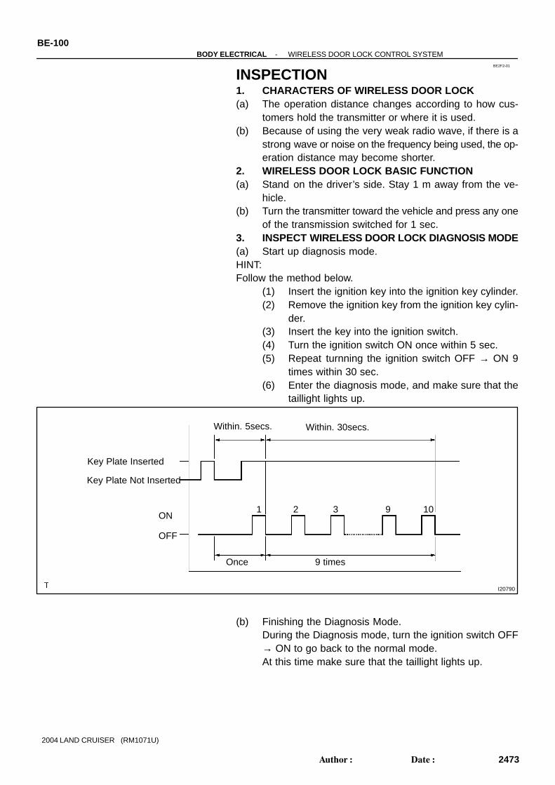
BE2F2-01
I20790
Key Plate Inserted
ON
OFF
Within. 5secs.
1
Key Plate Not Inserted
2 3 9 10
Within. 30secs.
Once 9 times
BE-100-BODY ELECTRICAL WIRELESS DOOR LOCK CONTROL SYSTEM
2473Author: Date:
2004 LAND CRUISER (RM1071U)
INSPECTION1. CHARACTERS OF WIRELESS DOOR LOCK(a) The operation distance changes according to how cus-
tomers hold the transmitter or where it is used.(b) Because of using the very weak radio wave, if there is a
strong wave or noise on the frequency being used, the op-eration distance may become shorter.
2. WIRELESS DOOR LOCK BASIC FUNCTION(a) Stand on the driver’s side. Stay 1 m away from the ve-
hicle.(b) Turn the transmitter toward the vehicle and press any one
of the transmission switched for 1 sec.3. INSPECT WIRELESS DOOR LOCK DIAGNOSIS MODE(a) Start up diagnosis mode.HINT:Follow the method below.
(1) Insert the ignition key into the ignition key cylinder.(2) Remove the ignition key from the ignition key cylin-
der.(3) Insert the key into the ignition switch.(4) Turn the ignition switch ON once within 5 sec.(5) Repeat turnning the ignition switch OFF → ON 9
times within 30 sec.(6) Enter the diagnosis mode, and make sure that the
taillight lights up.
(b) Finishing the Diagnosis Mode.During the Diagnosis mode, turn the ignition switch OFF→ ON to go back to the normal mode.At this time make sure that the taillight lights up.

I20456
(1) LOCK switch
(2) UNLOCK switch
(3) Luggage door switch
(4) Disagreement of recognition code or rolling code.
0.13secs. 0.5secs.
0.13secs. 0.25secs. 0.5secs.
0.5secs.0.5secs.
OFF
ON
OFF
ON
OFF
ON
OFF
ON
While receiving
I04149
-BODY ELECTRICAL WIRELESS DOOR LOCK CONTROL SYSTEMBE-101
2474Author: Date:
2004 LAND CRUISER (RM1071U)
(c) Diagnosis Mode Check.HINT:Check how the taillight lights up when pressing each transmitterswitch.
(1) LOCK switch(2) UNLOCK switch(3) Luggage door switch(4) Disagreement of recognition code or rolling code.
HINT:If (4) is detected in the Diagnosis Check, conduct the recogni-tion code registration.
(5) No response from the taillight.HINT:Conduct the following checks.
Wireless door lock transmitter. Wireless door lock receiver.
4. INSPECT WIRELESS DOOR LOCK TRANSMITTEROPERATION
HINT:Refer to ”Wireless door lock control receiver and transmitter re-placement”.(a) Using a screwdriver, remove the screw and cover.(b) Remove the battery (lithium battery).
(c) Install a new or normal battery (lithium battery).HINT:When a new or normal battery can not be obtained, connect 2new 1.5 V batteries in series, connect the battery (+) to the bat-tery receptacle side terminal and battery (-) to the bottom termi-nal, then apply 3 V voltage to the transmitter.(d) In the location where is approx. 1 M away from driver’s
outside handle in the right direction, face the key plate ofthe transmitter to the vehicle, and check the transmitteroperation when pressing transmission switch on the sideof the transmitter body.
(e) Install the battery (lithium battery).(f) Install a cover so that O-ring is not distorted or slipped off.(g) Using a screwdriver, tighten the screw.Standard: Remote control of vehicle door lock can be operated. LED lights up more than once.
HINT: The minimum operation distance differs according to op-
erator, the way of holding, and location.

I04150
I07522
BE-102-BODY ELECTRICAL WIRELESS DOOR LOCK CONTROL SYSTEM
2475Author: Date:
2004 LAND CRUISER (RM1071U)
As weak wave is used, operation distance might be short-ened when noise is detected in strong wave or used fre-quency.
5. CHECK BATTERY CAPACITYHINT: Make sure to use the TOYOTA electrical tester. With the battery unloaded, judge can not be made wheth-
er the battery is available or not on the test. When the transmitter is faulty, the energy amount left in
the battery might not be checked correctly. On the lithium battery used for the transmitter, the voltage
more than 2.5 V with the battery unloaded is shown on thetester until the energy is completely consumed.Accordingly when inspecting the energy amount left in thebattery, it is necessary to measure the voltage when thebattery is loaded. (1.2 kΩ).
(a) Remove the 2 screws and cover using a (-) driver.(b) Remove the battery (lithium battery) from the transmitter.(c) Connect the lead to the (-) terminal of the transmitter and
install the battery.
(d) Connect the (+) tester to the (+) battery (lithium battery),and (-) tester to the lead respectively.
(e) Press one of the transmitting switches on the transmitterfor approx. 1 second.
(f) Press the transmitting switch on the transmitter again tocheck the voltage.Standard: 2.1 V or more
HINT: When the temperature of the battery is low, the judge can
not be made correctly.When the outcome of the test is less than 2.1 V, conductthe test again after leaving the battery in the place at 18°C for more than 30 minutes.
By auto power off function, the voltage becomes no loadvoltage (more than 2.5 V) condition 20 seconds after theswitch was pressed. Make sure to read the voltage before of it.

I25814
Wire Harness Side
-BODY ELECTRICAL WIRELESS DOOR LOCK CONTROL SYSTEMBE-103
2476Author: Date:
2004 LAND CRUISER (RM1071U)
High voltage might be shown 1 to 2 times after leaving thebattery, judge should be made with the voltage shown atthe 3rd time or later.
(g) Disconnect the lead.(h) Set the battery (lithium battery) in the transmitter.(i) Install the cover, so that the O-ring is not distorted or
slipped off.(j) Using a screwdriver, tighten the 2 screws.
6. INSPECT WIRELESS DOOR LOCK CONTROL TUNERCIRCUIT
Disconnect the connector from the tuner and inspect the con-nector on the wire harness side, as shown.
Tester connection Condition Specified condition
1 (E) - Ground Constant Continuity
2 (RDA) - GroundIgnition switch OFF, without key, all doors
closed,, and transmitter switch OFF → ONBelow 1 V ↔ 6 V
5 (+B) - Ground - Repeatedly chage 0 - 5V
If the circuit is not as specified, inspect the circuit connected toother parts.

BE0CH-09
I25815
Transmitter:
Door Key Lock andUnlock Switch
Front Door Lock Assembly Front Door Lock Motor Front Door Unlock Detection Switch
Rear Door Lock Assembly Rear Door Lock Motor Rear Door Unlock Detection Switch
Front Door Lock Assembly Front Door Lock Motor Front Door UnlockDetection Switch
Rear Door Lock Assembly Rear Door Lock Motor Rear Door UnlockDetection Switch
Ignition Switch
Wireless Door Lock ECU
BE-98-BODY ELECTRICAL WIRELESS DOOR LOCK CONTROL SYSTEM
2471Author: Date:
2004 LAND CRUISER (RM1071U)
LOCATION

BE0CI-07
-BODY ELECTRICAL WIRELESS DOOR LOCK CONTROL SYSTEMBE-99
2472Author: Date:
2004 LAND CRUISER (RM1071U)
PRE-CHECK1. CHARACTERS OF WIRELESS DOOR LOCK(a) The operation distance changes according to how customers hold the transmitter or where it is used.(b) Because of using the very weak radio wave, if there is a strong wave or noise on the frequency being
used, the operation distance may become shorter.2. WIRELESS DOOR LOCK BASIC FUNCTION(a) Stand on the driver’s side. Stay 1 m away from the vehicle.(b) Turn the transmitter toward the vehicle and press any one of the transmission switched for 1 sec.
BE226-04
-BODY ELECTRICAL WIRELESS DOOR LOCK CONTROL SYSTEMBE-93
2466Author: Date:
2004 LAND CRUISER (RM1071U)
WIRELESS DOOR LOCK CONTROL SYSTEMREGISTRATION PROCEDUREHOW TO CODE REGISTRATIONNOTICE:When replacing the theft deterrent ECU or transmitter, registration of recognition code is necessarybecause they are provided as a single components.(a) Select the operation mode to perform from the following operation modes.
Add mode Rewrite mode Prohibition mode Confirmation mode
HINT: The ”Add mode” is for adding the newly recognized codes for registration while the already registered
codes are retained. This mode is used when the transmitter is added. When the number of the regis-tered codes exceeds 4 codes, the previously registered codes will be erased in order, staring from thefirst registered code.
The ”Rewrite mode” is for erasing all the registered codes and registering newly recognized codes only.This mode is used when the transmitter or the door control receiver is replaced.
The ”Prohibition mode” is for erasing all the registered codes to prohibit the wireless door lock opera-tion. This mode is used when the transmitter is lost.
The ”Confirmation mode” is for confirming the number of recognition codes that are registered. Thismode is used to check the number of registered codes when new codes are added to the registration,etc.
(b) Follow the chart on the following page to register the transmitter recognition code to the theft deterrentECU.
HINT: When procedure is out of the specified, the registration operation is cancelled. Maximum 4 recognition codes can be registered.

START
The vehicle should be in the following conditions: Ignition switch ON
Hand-held tester operation:1. Select ”L/C 100” from the menu.2. Select ”TDS” (Theft Deterrent System).3. Select ”WIRELESS REGISTRATION”.After the above operations, proceed to the succeeding operations according to the prompts on the tester screen.
Transmitter SW Operation:HINT: Perform this operation during the countdown screen.
Press both lock and unlock SW. (Between 1 and 1.5 sec.)
Press any one of SW. (For more than 1 sec.)
This wireless buzzer sounds when the registration is completed normally.
Continue the registration. Register other transmitters?Or
Finish the registration?
Finish the registration.
END
HINT: Select the next step on the tester screen.
Within 3 sec.
BE-94-BODY ELECTRICAL WIRELESS DOOR LOCK CONTROL SYSTEM
2467Author: Date:
2004 LAND CRUISER (RM1071U)
(c) By TOYOTA Hand-Held Tester
HINT:This page is to show briefly the registration procedure using the hand-held tester.For detailed procedures, please refer to the prompts on the tester screen.The number of currently registered codes can be checked out on the first screen of the WIRELESS REG-ISTRATION.

Close→open→close→open
START
The vehicle should be in the following conditions: Driver door open (Other doors are closed).
Insert and remove the key into/from the ignition cylinder twice.Insert→remove →insert→remove
HINT: If the IG switch operation isnot performed with the specifiednumber of times (If it is 4 times, 6times or more), this operation isfinished with no response.
HINT: The registration operation iscancelled if each operation is notcompleted within the specifiedtime.
No key inserted in the IG key cylinder.
Close and open the driver door twice.Close→open→close→open
Insert and remove the key into/from the ignition cylinder once.Insert→remove
Insert the key into the ignition key cylinder.Close all the doors.
Mode Selection
Turn the IG SW ON←→LOCK once.
Add modeTurn the IG SW ON←→LOCK twice.
Rewrite modeTurn the IG SW ON←→LOCK 3 times.
Confirmation modeTurn the IG SW ON←→LOCK 5 times.
Prohibition mode
Remove the key from the IG key cylinder.
Within 5 sec.
Within 40 sec.
Within 40 sec.
Within 40 sec.
Close and open the driver door twice.
-BODY ELECTRICAL WIRELESS DOOR LOCK CONTROL SYSTEMBE-95
2468Author: Date:
2004 LAND CRUISER (RM1071U)
(d) By Switch Operation:

Add mode:
Response of whether or not being moved to each mode is given withthe number of times of door lock working (lock/unlock).
Within 3 sec.
Within 40 sec.
Within 3 sec.
Rewrite mode: Confirmation mode:
Prohibition mode:
once*1twice*1The number of times equivalent to the numberof currently registered codes*25 times*1
HINT: The confirmation mode and the prohibition mode are finished after the responses.
Transmitter SW Operation:
Press both lock and unlock SW. (Between 1 and 1.5 sec.)
Press any one of SW. (For more than 1 sec.)
Response of whether or not the registration is completed is given in theform of the number of times of door lock operations (lock/unlock opera-tion).
Register other transmitters?
orFinish the registration?
Finish the registration.
Within 3 sec.
Confirmation modeProhibition mode
ENDAdd mode,Rewrite mode
When registration is completed:When registration is not completed:
once*1twice*1
Insert the key into the IG key cylinder.
Perform one of the following operations to finish the Add mode and theRewrite mode.
Open any one of the doors. Wait for 40 sec. after the code registration.HINT: In case of registering 4 codes at a time, the mode will be finishedwhen the 4th code is registered.
Continuethe registration.
Within 40 sec.
BE-96-BODY ELECTRICAL WIRELESS DOOR LOCK CONTROL SYSTEM
2469Author: Date:
2004 LAND CRUISER (RM1071U)

Door Lock Motor
LOCK
UNLOCK
*1:
Door Lock Motor
LOCK
UNLOCK
*2:
1 Sec. 1 Sec.
2 Sec. 2 Sec.
-BODY ELECTRICAL WIRELESS DOOR LOCK CONTROL SYSTEMBE-97
2470Author: Date:
2004 LAND CRUISER (RM1071U)
HINT:Operation cycle of the door lock (lock/unlock operation)

I26371
BE23K-02
I04155
O-Ring
I04156
Terminal
BE-104-BODY ELECTRICAL WIRELESS DOOR LOCK CONTROL SYSTEM
2477Author: Date:
2004 LAND CRUISER (RM1071U)
REPLACEMENTREPLACE TRANSMITTER (LITHIUM) BATTERYNOTICE:Special caution should be taken for handling each compo-nent as they are precision electronic components.(a) Using a screwdriver, remove the screw and cover.NOTICE:Do not pry out the cover forcibly.HINT:Push the cover with a finger as shown in the illustration, so thatthere becomes clearance, then pry out the cover from thatclearance.(b) Remove the transmitter.
(c) Using a screwdriver, remove the 2 screws and cover.(d) Remove the battery (lithium battery).NOTICE: Do not push the terminals with a finger. If prying up the battery (lithium battery) forcibly to re-
move, the terminals are deformed.
(e) Install a battery (lithium battery) as shown in the illustra-tion.
NOTICE:Face the battery upward. Take care not to deform the termi-nals.(f) Check that O-ring is not distorted or slipped off, and
install the cover.(g) Using a screwdriver, tighten the 2 screws.NOTICE:When the shrews are tightened loosely, it might causefaulty contact of battery (lithium battery) and terminals.(h) Assemble the transmitter to the key plate and the cover.(i) Using a screwdriver, tighten the screw.