bmf055 extension board – user guide - mouser electronics · either a usb connection or a...
TRANSCRIPT

Application Note: BMF055 Extension Board – User guide
Document Revision 1.0
Document Release
October 2015
Document Number BST-BMF055-AN001-00
Technical Reference
0 273 141 235
Notes Data in this document are subject to change without notice. Product photos and pictures are for illustration purposes only and may differ from the real product’s appearance.
Application Note
BMF055 Extension Board – User guide
Bosch Sensortec

Application Note
BMF055 Extension Board – User guide Page 2
BST-BMF055-AN 001-00 | Revi si on 1.0 | October 2015 Bosch Sensortec
© Bosch Sensortec GmbH reserves al l rights even i n the event of i ndustrial property rights. We reserve all ri ghts of di sposal such as copyi ng and passi ng on to third parti es. BOSCH and the symbol are regi stered trademarks of Robert Bosch GmbH, Germany.
Note: Speci fi cati ons within thi s document are subj ect to change without noti ce.
Contents
1 Preface ...................................................................................................................... 3
2 Components............................................................................................................. 4
2.1 Power ...................................................................................................................................................... 5
2.2 Arduino ................................................................................................................................................... 5
2.3 Customization..................................................................................................................................... 5
3 Necessary Connections ......................................................................................... 6
3.1 Shuttle board....................................................................................................................................... 6
3.2 Power ...................................................................................................................................................... 6
3.3 Power jumper ..................................................................................................................................... 6
3.4 Programmer/ debugger connection ....................................................................................... 6
4 Connections for Reference Examples ................................................................. 7
5 Quick Setup for Reference Examples .................................................................. 8
5.1 Software and Extensions ............................................................................................................. 8
5.2 Hardware............................................................................................................................................... 8
5.3 Run the Project .................................................................................................................................. 9
5.4 Check the Use-case ....................................................................................................................... 9
6 BMF055 Shuttle Board.......................................................................................... 11
6.1 Power ................................................................................................................................................... 12
6.2 Programming/ Debugging ........................................................................................................ 12
7 References ............................................................................................................. 13
8 Legal disclaimer .................................................................................................... 14
8.1 Engineering samples................................................................................................................... 14
8.2 Product Use...................................................................................................................................... 14
8.3 Application Examples and Hints ........................................................................................... 14
9 Document History and Modifications ................................................................ 15

Application Note
BMF055 Extension Board – User guide Page 3
BST-BMF055-AN 001-00 | Revi si on 1.0 | October 2015 Bosch Sensortec
© Bosch Sensortec GmbH reserves al l rights even i n the event of i ndustrial property rights. We reserve all ri ghts of di sposal such as copyi ng and passi ng on to third parti es. BOSCH and the symbol are regi stered trademarks of Robert Bosch GmbH, Germany.
Note: Speci fi cati ons within thi s document are subj ect to change without noti ce.
1 Preface This document is a user guide to setup the BMF055 application board. It describes the modules on the board and shows the necessary connections to program the chip and run the reference examples provided by Bosch Sensortec. The examples can be downloaded on Atmel Gallery.

Application Note
BMF055 Extension Board – User guide Page 4
BST-BMF055-AN 001-00 | Revi si on 1.0 | October 2015 Bosch Sensortec
© Bosch Sensortec GmbH reserves al l rights even i n the event of i ndustrial property rights. We reserve all ri ghts of di sposal such as copyi ng and passi ng on to third parti es. BOSCH and the symbol are regi stered trademarks of Robert Bosch GmbH, Germany.
Note: Speci fi cati ons within thi s document are subj ect to change without noti ce.
2 Components
Figure 1 - BMF055 application board's compinents
1 – USB Power Connecter
2 – Power source selection pins (USB/ Arduino)
3 – Programmer/ Debugger JTAG Connector
4 – BMF055 shuttle board connector
5 – Customization pins connected to shuttle board connector
6 – Customization pins connected to Arduino pins
7 – Arduino Connector

Application Note
BMF055 Extension Board – User guide Page 5
BST-BMF055-AN 001-00 | Revi si on 1.0 | October 2015 Bosch Sensortec
© Bosch Sensortec GmbH reserves al l rights even i n the event of i ndustrial property rights. We reserve all ri ghts of di sposal such as copyi ng and passi ng on to third parti es. BOSCH and the symbol are regi stered trademarks of Robert Bosch GmbH, Germany.
Note: Speci fi cati ons within thi s document are subj ect to change without noti ce.
2.1 Power
The board can be powered either via a USB cable or an Arduino board. In the former case a jumper should connect pins number 2 and 3 of the power source selection pins. In the latter case a connection between pins 1 and 2 are required.
2.2 Arduino
BMF055 application board can be connected to an Arduino board as a shield. The male connectors at the bottom side provide this possibility. As shown in Figure 2 further shields can also be connected to the female connectors.
Figure 2 - Connected to Arduino UNO and another shield
2.3 Customization
The only connections to the Arduino and Shuttle board connectors on the board are VDD and GND. The other pins are left unconnected so that users can customize how they desire. There are the two sets of male connectors available on the board: The inner set (Number 5 in Figure 1) is connected to the shuttle board pins in a one-to-one manner and the outer one (Number 6 in Figure 1) is connected to the Arduino pins in the same manner. These connectors can be used for the customization.

Application Note
BMF055 Extension Board – User guide Page 6
BST-BMF055-AN 001-00 | Revi si on 1.0 | October 2015 Bosch Sensortec
© Bosch Sensortec GmbH reserves al l rights even i n the event of i ndustrial property rights. We reserve all ri ghts of di sposal such as copyi ng and passi ng on to third parti es. BOSCH and the symbol are regi stered trademarks of Robert Bosch GmbH, Germany.
Note: Speci fi cati ons within thi s document are subj ect to change without noti ce.
3 Necessary Connections
3.1 Shuttle board
The BMF055 shuttle board should be plugged in to the socket on the application board in a way that pin number 1 of the shuttle is connected to the pin number 1 of the socket.
3.2 Power
Either a USB connection or a connection to an Arduino board is required to provide power for the board.
3.3 Power jumper
If the application board’s power is provided by an Arduino board the jumper J11 must connect pins number 1 and 2.
Otherwise, if a USB cable provides the power, the jumper J11 must connect pins number 3 and 2.
3.4 Programmer/ debugger connection
To program the microcontroller in BMF055 a programmer/ debugger is required. The board has a standard JTAG connector to for this purpose.
Application Note
BMF055 Extension Board – User guide Page 7
BST-BMF055-AN 001-00 | Revi si on 1.0 | October 2015 Bosch Sensortec
© Bosch Sensortec GmbH reserves al l rights even i n the event of i ndustrial property rights. We reserve all ri ghts of di sposal such as copyi ng and passi ng on to third parti es. BOSCH and the symbol are regi stered trademarks of Robert Bosch GmbH, Germany.
Note: Speci fi cati ons within thi s document are subj ect to change without noti ce.
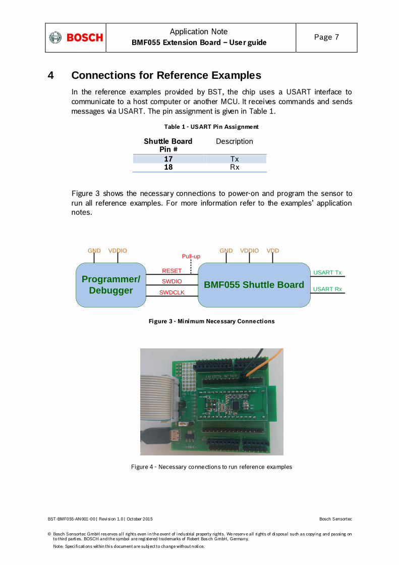
4 Connections for Reference Examples In the reference examples provided by BST, the chip uses a USART interface to communicate to a host computer or another MCU. It receives commands and sends messages via USART. The pin assignment is given in Table 1.
Table 1 - USART Pin Assignment
Shuttle Board Pin #
Description
17 Tx 18 Rx
Figure 3 shows the necessary connections to power-on and program the sensor to run all reference examples. For more information refer to the examples’ application notes.
BMF055 Shuttle BoardRESET
Programmer/ Debugger SWDCLK
SWDIO
GND VDDIO
USART Tx
USART Rx
Pull-upGND VDDIO VDD
Figure 3 - Minimum Necessary Connections
Figure 4 - Necessary connections to run reference examples

Application Note
BMF055 Extension Board – User guide Page 8
BST-BMF055-AN 001-00 | Revi si on 1.0 | October 2015 Bosch Sensortec
© Bosch Sensortec GmbH reserves al l rights even i n the event of i ndustrial property rights. We reserve all ri ghts of di sposal such as copyi ng and passi ng on to third parti es. BOSCH and the symbol are regi stered trademarks of Robert Bosch GmbH, Germany.
Note: Speci fi cati ons within thi s document are subj ect to change without noti ce.
5 Quick Setup for Reference Examples This chapter gives step by step instructions on how to start running this example on a BMF055 Shuttle Board.
5.1 Software and Extensions
1. Install the latest version of Atmel Studio from Atmel website
• Open Atmel Studio
2. Go to “Tools -> Extension Manager” and install the latest version of Atmel Software Framework (Version used in this extension is 3.26.0)
3. Go to “Tools -> Extension Manager” and search for “BMF055 Shuttle Board – [Example]” extension from Bosch Sensortec GmbH (BST) and install it
4. Go to “Tools -> Extension Manager” and search for “Terminal for Atmel Studio” extension from Atmel and install it (It is not necessary to install this extension if you are going to use another terminal software)
5. Restart Atmel Studio
6. Go to “File -> New -> Example Projects”
7. “Below BST – Bosch Sensortec GmbH” find the project named “BMF055_SHUTTLE_BOARD_ [EXAMPLE] – atsamd20j18a”
8. Select it and press “OK” button
9. Read and accept the license agreement and press “Finish” button to create a new example project
5.2 Hardware
10. Establish the minimum necessary connections; including power, reset and programmer/debugger.
11. Establish a USART connection between the shuttle board and a host computer*. Use bridges if necessary.
12. Install required drivers for your virtual COM port.
13. Go to “Start Menu -> Control Panel -> Device Manager”
14. Below “Ports (COM and LPT)” find the virtual COM port that you are going to use and note the COM Port Number
15. In Atmel Studio go to “Project -> Properties” and select the tab named “Tool”
* It is assumed that the shuttle board would be interfaced to a terminal software running on a host computer.

Application Note
BMF055 Extension Board – User guide Page 9
BST-BMF055-AN 001-00 | Revi si on 1.0 | October 2015 Bosch Sensortec
© Bosch Sensortec GmbH reserves al l rights even i n the event of i ndustrial property rights. We reserve all ri ghts of di sposal such as copyi ng and passi ng on to third parti es. BOSCH and the symbol are regi stered trademarks of Robert Bosch GmbH, Germany.
Note: Speci fi cati ons within thi s document are subj ect to change without noti ce.
16. Below “Selected debugger/programmer” select the “SAM-ICE” tool. And select “SWD” as the interface and save the changes.
5.3 Run the Project
17. In Atmel Studio to “Build -> Build Solution”
The build process should succeed with no errors or warnings. (Figure 5)
18. Go to “Debug -> Start Without Debugging” (Figure 6)
19. Wait for the process to be done.
(Notice the “Ready” message below, on the status bar)
20. Run and connect the required software (e.g. Terminal) on the host computer if required
5.4 Check the Use-case*
21. Check the application as explained in the example’s application note.
Figure 5 - Build Project
* For detailed information refer to Error! Reference source not found..

Application Note
BMF055 Extension Board – User guide Page 10
BST-BMF055-AN 001-00 | Revi si on 1.0 | October 2015 Bosch Sensortec
© Bosch Sensortec GmbH reserves al l rights even i n the event of i ndustrial property rights. We reserve all ri ghts of di sposal such as copyi ng and passi ng on to third parti es. BOSCH and the symbol are regi stered trademarks of Robert Bosch GmbH, Germany.
Note: Speci fi cati ons within thi s document are subj ect to change without noti ce.
Figure 6 - Start without Debugging

Application Note
BMF055 Extension Board – User guide Page 11
BST-BMF055-AN 001-00 | Revi si on 1.0 | October 2015 Bosch Sensortec
© Bosch Sensortec GmbH reserves al l rights even i n the event of i ndustrial property rights. We reserve all ri ghts of di sposal such as copyi ng and passi ng on to third parti es. BOSCH and the symbol are regi stered trademarks of Robert Bosch GmbH, Germany.
Note: Speci fi cati ons within thi s document are subj ect to change without noti ce.
6 BMF055 Shuttle Board Bosch Sensortec BMF055 shuttle board is a PCB with a BMF055 Orientation Sensor mounted on it. It has the required decoupling capacitors, an external 32 KHz crystal and its load capacitors and allows easy access to the sensors pins via a simple socket.
Table 2 - BMF055 Shuttle Board Pin-out
Pin No. Pin Name BMF055 Pin Connected
SAMD20 Pin Connected
Description
1 VDD 3 VDD 2 VDDIO 28 - VDDIO 3 GND 2, 25 - GND 4 MISO - - DNC 5 MOSI - - DNC 6 SCK - - DNC 7 CS - - DNC 8 IO5/INTA 6 PB00 GPIO 9 IO0 5 PB01 GPIO 10 COD_GND - - DNC 11 COD_GND - - DNC 12 COD_GND - - DNC 13 COD_GND - - DNC 14 IO1 4 PB02 GPIO 15 IO2 16 PA22 GPIO 16 IO3 15 PA23 GPIO 17 SDA 20 PB16 GPIO 18 SCL 19 PB17 GPIO 19 IO8 11 RESET RESET 20 INTB/IO6 10 PA28 GPIO 21 INTC/IO7 14 PA24 GPIO 22 IO4 17 PA21 GPIO 23 COD_GND - - DNC 24 COD_PULL - - DNC 25 COD_GND - - DNC 26 COD_GND - - DNC 27 COD_PULL - - DNC 28 COD_PULL - - DNC 29 SWCLK 8 PA30 Debugging CLK 30 SWDIO 7 PA31 Debugging IO

Application Note
BMF055 Extension Board – User guide Page 12
BST-BMF055-AN 001-00 | Revi si on 1.0 | October 2015 Bosch Sensortec
© Bosch Sensortec GmbH reserves al l rights even i n the event of i ndustrial property rights. We reserve all ri ghts of di sposal such as copyi ng and passi ng on to third parti es. BOSCH and the symbol are regi stered trademarks of Robert Bosch GmbH, Germany.
Note: Speci fi cati ons within thi s document are subj ect to change without noti ce.
The shuttle board can be plugged into Bosch Sensortec development tools, custom designed boards or breadboards.
6.1 Power
BMF055 has two distinct power supply pins:
• VDD is the main power supply for the internal sensors • VDDIO is a separate power supply pin used for the supply of the MCU and the
digital interfaces
The voltage supply range for VDD is 2.4V to 3.6V and for VDDIO is 1.7V to 3.6V.
For the switching sequence of power supply VDD and VDDIO it is mandatory that VDD
is powered on and driven to the specified level before or at the same time as VDDI O is powered ON. Otherwise there are no limitations on the voltage levels of both pins relative to each other, as long as they are used within the specified operating range.
6.2 Programming/ Debugging
Programming and debugging of the chip is done Serial Wire Debug Interface available. Any debugger that supports the interface can be used. (e.g Atmel SAM-ICE)

Application Note
BMF055 Extension Board – User guide Page 13
BST-BMF055-AN 001-00 | Revi si on 1.0 | October 2015 Bosch Sensortec
© Bosch Sensortec GmbH reserves al l rights even i n the event of i ndustrial property rights. We reserve all ri ghts of di sposal such as copyi ng and passi ng on to third parti es. BOSCH and the symbol are regi stered trademarks of Robert Bosch GmbH, Germany.
Note: Speci fi cati ons within thi s document are subj ect to change without noti ce.
7 References
Atmel-42129-SAM-D20_Datasheet
http://www.atmel.com/Images/atmel-42129-sam-d20_datasheet.pdf

Application Note
BMF055 Extension Board – User guide Page 14
BST-BMF055-AN 001-00 | Revi si on 1.0 | October 2015 Bosch Sensortec
© Bosch Sensortec GmbH reserves al l rights even i n the event of i ndustrial property rights. We reserve all ri ghts of di sposal such as copyi ng and passi ng on to third parti es. BOSCH and the symbol are regi stered trademarks of Robert Bosch GmbH, Germany.
Note: Speci fi cati ons within thi s document are subj ect to change without noti ce.
8 Legal disclaimer
8.1 Engineering samples
Engineering Samples are marked with an asterisk (*) or (e) or (E). Samples may vary from the valid technical specifications of the product series contained in this data sheet. They are therefore not intended or fit for resale to third parties or for use in end products. Their sole purpose is internal client testing. The testing of an engineering sample may in no way replace the testing of a product series. Bosch Sensortec assumes no liability for the use of engineering samples. The Purchaser shall indemnify Bosch Sensortec from all claims arising from the use of engineering samples.
8.2 Product Use
Bosch Sensortec products are developed for the consumer goods industry. They may only be used within the parameters of this product data sheet. They are not fit for use in life-sustaining or security sensitive systems. Security sensitive systems are those for which a malfunction is expected to lead to bodily harm or significant property damage. In addition, they are not fit for use in products which interact with motor vehicle systems.
The resale and/or use of products are at the purchaser’s own risk and his own responsibility. The examination of fitness for the intended use is the sole responsibility of the Purchaser.
The purchaser shall indemnify Bosch Sensortec from all third party claims arising from any product use not covered by the parameters of this product data sheet or not approved by Bosch Sensortec and reimburse Bosch Sensortec for all costs in connection with such claims.
The purchaser must monitor the market for the purchased products, particularly with regard to product safety, and inform Bosch Sensortec without delay of all security relevant incidents.
8.3 Application Examples and Hints
With respect to any examples or hints given herein, any typical values stated herein and/or any information regarding the application of the device, Bosch Sensortec hereby disclaims any and all warranties and liabilities of any kind, including without limitation warranties of non-infringement of intellectual property rights or copyrights of any third party. The information given in this document shall in no event be regarded as a guarantee of conditions or characteristics. They are provided for illustrative purposes only and no evaluation regarding infringement of intellectual property rights or copyrights or regarding functionality, performance or error has been made.

Application Note
BMF055 Extension Board – User guide Page 15
BST-BMF055-AN 001-00 | Revi si on 1.0 | October 2015 Bosch Sensortec
© Bosch Sensortec GmbH reserves al l rights even i n the event of i ndustrial property rights. We reserve all ri ghts of di sposal such as copyi ng and passi ng on to third parti es. BOSCH and the symbol are regi stered trademarks of Robert Bosch GmbH, Germany.
Note: Speci fi cati ons within thi s document are subj ect to change without noti ce.
9 Document History and Modifications
Rev. No. Chapter Description of Modification/ Changes Date 1.0 Document Created 07.10.2015
Bosch Sensortec GmbH
Gerhard-Kindler-Strasse 8
72770 Reutlingen / Germany
www.bosch-sensortec.com
Modifications reserved | Printed in Germany
Specifications subject to change without notice