bmc musculoskeletal disorders biomed centralfuh/personal/thrsimulatorthesoftware... · bmc...
TRANSCRIPT

BioMed CentralBMC Musculoskeletal Disorders
ss
Open AcceSoftwareTHR Simulator – the software for generating radiographs of THR prosthesisTai-Yin Wu1, Rong-Sen Yang2, Chiou-Shann Fuh3, Sheng-Mou Hou2 and Chen-Kun Liaw*2,4,5,6Address: 1Taipei City Hospital, Renai Branch, Tapei City, Taiwan, 2Department of Orthopaedics, College of Medicine, National Taiwan University & Hospital, Tapei City, Taiwan, 3Institute of Computer Science and Information Engineering, National Taiwan University, Tapei City, Taiwan, 4Department of Orthopaedics, Tao-Yuan General Hospital, Tao-Yuan, Taiwan, 5Minghsin University of Science and Technology, Hsinchu County, Taiwan and 6Ming Chuan University, Tapei City, Taiwan
Email: Tai-Yin Wu - [email protected]; Rong-Sen Yang - [email protected]; Chiou-Shann Fuh - [email protected]; Sheng-Mou Hou - [email protected]; Chen-Kun Liaw* - [email protected]
* Corresponding author
AbstractBackground: Measuring the orientation of acetabular cup after total hip arthroplasty is importantfor prognosis. The verification of these measurement methods will be easier and more feasible ifwe can synthesize prosthesis radiographs in each simulated condition. One reported method usedan expensive mechanical device with an indeterminable precision. We thus develop a program, THRSimulator, to directly synthesize digital radiographs of prostheses for further analysis.
Under Windows platform and using Borland C++ Builder programming tool, we developed theTHR Simulator. We first built a mathematical model of acetabulum and femoral head. The data ofthe real dimension of prosthesis was adopted to generate the radiograph of hip prosthesis. Thenwith the ray tracing algorithm, we calculated the thickness each X-ray beam passed, and thentransformed to grey scale by mapping function which was derived by fitting the exponential functionfrom the phantom image. Finally we could generate a simulated radiograph for further analysis.
Results: Using THR Simulator, the users can incorporate many parameters together for radiographsynthesis. These parameters include thickness, film size, tube distance, film distance, anteversion,abduction, upper wear, medial wear, and posterior wear. These parameters are adequate for anyradiographic measurement research. This THR Simulator has been used in two studies, and theerrors are within 2° for anteversion and 0.2 mm for wearing measurement.
Conclusion: We design a program, THR Simulator that can synthesize prosthesis radiographs. Sucha program can be applied in future studies for further analysis and validation of measurement ofvarious parameters of pelvis after total hip arthroplasty.
BackgroundMeasuring the orientation of acetabulum cup and thewearing of insert on plain radiograph of patients who
underwent total hip arthroplasty is important for progno-sis[1]. Verifying the orientation measurement [1-6] andwearing [7-14] methods are both important, which may
Published: 16 January 2009
BMC Musculoskeletal Disorders 2009, 10:8 doi:10.1186/1471-2474-10-8
Received: 24 March 2008Accepted: 16 January 2009
This article is available from: http://www.biomedcentral.com/1471-2474/10/8
© 2009 Wu et al; licensee BioMed Central Ltd. This is an Open Access article distributed under the terms of the Creative Commons Attribution License (http://creativecommons.org/licenses/by/2.0), which permits unrestricted use, distribution, and reproduction in any medium, provided the original work is properly cited.
Page 1 of 8(page number not for citation purposes)

BMC Musculoskeletal Disorders 2009, 10:8 http://www.biomedcentral.com/1471-2474/10/8
require a simulator to mimic every situation for such ananalysis[1]. Mechanical simulator has once been reportedin a study to measure the wearing of acetabular insert [7].Although such a mechanical device is straightforward,there are disadvantages including expensive price, unde-termined precision, as well as requiring image processingfrom radiograph to digital form. Every processing stepmay cause error and interfere with the final precision.
We thus developed our own THR Simulator [Figure 1] bydesigning a software program that can be used to generatedigital radiographs directly. The early edition of THR Sim-ulator software has been used to simulate 45 radiographsof total hip arthroplasties with 15 different anteversionsranging from 15°–29°, and then to verify the protractorwhich was designed to measure the anteversion of acetab-ular cup [1]. We have corrected some mistakes and incor-
porated some new features in the latest edition. We hopethis program can provide researchers an easy instrumentto develop further measuring methods that can be appliedin plain radiograph.
ImplementationMany reported methods used Fourier transformation tofasten the process in generating the radiographs fromcomputed tomography data [15,16]. However, Fouriertransformation may decrease the precision, which is thefirst priority in the measurement analysis on plain radio-graphs. On the other hand, ray tracing, which is popularin computer game, may be suitable for this transforma-tion. Unfortunately, current built libraries only providereflection images instead of transparent images that areneeded in our analysis. Therefore we have to build up our
(A) The THR Simulator and the basic figure of the generated radiographFigure 1(A) The THR Simulator and the basic figure of the generated radiograph. (B)We adjusted the wearing parameters and the result showed that the femoral head is centrally migrated. (C)We adjusted the film size parameter to simulate a smaller film in the same picture and the result is shown. (D)We chose the anteversion type as radiographic anteversion and the result is shown.
Page 2 of 8(page number not for citation purposes)

BMC Musculoskeletal Disorders 2009, 10:8 http://www.biomedcentral.com/1471-2474/10/8
Page 3 of 8
whole software program before practical application inthe plain radiographs.
Another problem is physics, i.e., once X-rays beam passthrough the prosthesis, they then generate the image onthe radiogram film. The grey scale on the radiogram filmis determined by the amount of the X-ray passed that isdependent on the thickness of the metal in the pathway.Such condition follows Beer-Lambert law.
Penetration = e-kbc (1)
k: molar absorbability
b: path length
c: concentration
The parameter k is different among various metals andradiation energy (kv in X-ray). In real X-ray machine, thedistribution of kv follows the rule of normal distribution,which is different among various X-ray machines. Aftercalculating the amount of X-rays passed, we need anotherformula to transfer them to grey scale.
Because too many parameters needed to be controlled tobuild up the software program, we tried another solution.We first took X-ray (63 kv, 17 mas) on the step-wedgephantom, made of titanium, which has 5 steps with anincrement of 1 mm thickness from 1 to 5 mm [Figure 2].Such a step-wedge phantom film was scanned. The greylevels on this X-ray radiogram were mapped as the opticaldensity values. We measured the optical density of each ofthe 5 wedges as well as that of the film background. Themapping function, from metal width to greyscale, is fit byexponential function. The mapping function is shown inFigure 2.
Our goal is to build a simulated total hip prosthesis. Vir-tually, femoral head equals to a ball.
x2+y2+z2<rf2 (2)
(x, y, z) is the point of the simulated three-dimensionalCartesian coordinate system. rf is the radius of femoralhead.
In our program, we make the ball move to simulate wear-ing of insert.
(x-dx)2+(y-dy)2+(z-dz)2<rf2 (3)
dx, dy, dz are femoral head movement in three directions.
Virtually, acetabulum is composed of two balls and oneplane.
x2+y2+z2<rao2 (4)
x2+y2+z2>rio2 (5)
ax+by+cz>0 (6)
rao means radius of acetabulum's outer shell, rio meansradius of acetabulum's inner shell, (a, b, c) means the nor-mal vector of the acetabulum which can be derived frominclination and anteversion of acetabulum. Liaw et al.derived the following formula for this process.[17]
(a, b, c) = (sin × cos , -cos × cos , sin ) (6.1)
Vector (a, b, c) means the normal vector of the acetabu-lum, means the inclination of acetabulum, means theanteversion of acetabulum, positive means anteversion,and negative means retroversion.
Theoretically, the X-ray source is set at (0,0,-dt). dt meanstube distance (the X-ray tube to the acetabulum center).The points at film are (xf, yf, df). (xf, yf) means point at film.df means distance from film to the acetabulum center.
(x, y, z) = (t xf, t yf, t(df+dt)-dt) 0<t <1 (7)
The ray-tracing algorithm means calculating every rayfrom X-ray source to film. We used formula (7), simulat-ing every X-ray from source to film. We then determinedthe total length the X-ray beam passed through femoralhead by calculating the length between the two extremesolutions of formulas (3) and (7). Finally, we came out atthe total length the X-ray beam passed through acetabu-lum by calculating length between the two extreme solu-tions of formulas (4), (5), (6), and (7). We use analyticalmathematics for these calculations. The detailed process isillustrated in Appendix section.
In summary, we first built a mathematical model ofacetabulum and femoral head, formulas (3) to (7). Thereal dimension data was adopted to generate the properprosthesis figure. Then we calculated the total thickness ofmetal the X-ray beams passed by the ray-tracing algo-rithm, and then transformed these digital data to greyscale by mapping function. Finally, the gray scale gener-ated for the prosthesis was shifted according to the afore-mentioned method. We could generate variousradiographs according to the different parameters used.
The functional parameters in the THR Simulator includethe following:
Thickness: refers to the thickness of the acetabulum shell.
Film size: refers to the X-ray film size it simulates.
(page number not for citation purposes)

BMC Musculoskeletal Disorders 2009, 10:8 http://www.biomedcentral.com/1471-2474/10/8
Page 4 of 8(page number not for citation purposes)
(A)The phantom, which is made of titanium with thickness from 1 mm to 5 mmFigure 2(A)The phantom, which is made of titanium with thickness from 1 mm to 5 mm. (B) The corresponding photoden-sity on the radiographs of the phantom is shown. (C)The mapping function (from thickness to grey scale). We fit the experi-ment points by an exponential function.

BMC Musculoskeletal Disorders 2009, 10:8 http://www.biomedcentral.com/1471-2474/10/8
Tube distance: refers to the distance from X-ray tube to theacetabulum center.
Film distance: refers to the distance from X-ray film to theacetabulum center.
Anteversion: refers to the version of the acetabular cup.The user can choose either version (anatomical, radiolog-ical, or operational) to simulate. Negative value meansretroversion.
Abduction: refers to the abduction (or inclination) of theacetabular cup.
Upper movement: refers to the femoral head movingupward.
Medial movement: refers to the femoral head movingmedially.
Posterior movement: refers to the femoral head movingposteriorly.
Picture size: refers to the size of picture file to simulate.
Results and discussionUnder Windows platform and using Borland C++ Builderprogramming tool, we developed the THR Simulator
shown in Figure 1. In the THR Simulator, the user canincorporate many parameters before generating a simu-lated radiograph, i.e., with different parameters adopted,we can generate different radiographs. These can be usedfor further analysis.
As shown in Figures 1 and 3, we can obtain different sim-ulated radiographs according to the parameters used.Thus we can demonstrate the function of such software,Simulator, in the application of the parameters.
Previously reported methods for measurement of acetab-ular cup orientation include mechanical simulator usedfor verifying insert wearing measuring methods [7], aswell as other methods adopting Fourier transformationalgorithm [15,16]. These methods have their own disad-vantages. The mechanical simulator can be used to gener-ate radiographs directly but has some inherent problems.The simulation process takes much time, about 50 sec-onds with Pentium III 500 MHz notebook. On the otherhand, other methods using Fourier transformation algo-rithm can do it in real time [15,16] at the expense of lowerprecision. Thus we abandoned Fourier transformationalgorithm and developed our own precise algorithm.
Our THR Simulator indeed improved the disadvantages ofthe above methods. The THR Simulator can incorporateseveral parameters for analysis at the same time. In prac-
The real radiograph is on the left, and the simulated one is on the rightFigure 3The real radiograph is on the left, and the simulated one is on the right. They show to be similar except some local features of the acetabulum and the bony noise.
Page 5 of 8(page number not for citation purposes)

BMC Musculoskeletal Disorders 2009, 10:8 http://www.biomedcentral.com/1471-2474/10/8
tice, we can obtain the basic parameters from the prosthe-sis venders, i.e. shell diameter, shell thickness to generatesimulated radiographs. Table 1 shows the parameters oftotal hip prostheses (U2, United Orthopedic Corp, Hsin-chu, Taiwan).
To make simulated radiographs more real, users cansuperimpose the synthesized radiographs onto real radio-graphs. We do not routinely recommend doing so becausethis action may make users misread patient's position andthus confuse the standardization process[17].
The early edition of THR Simulator software has been usedin two previous studies. One is to verify a new protractorin comparing with previous established mathematicalmethod of measuring acetabulum[1]. We used themethod in the earlier publication to simulate 45 radio-graphs of total hip arthroplasties with 15 differentanteversions ranging from 15°–29°, and then verified thetwo methods of measuring anteversion of acetabular cup[1]. The mean errors of both measuring methods arewithin two degrees. Figure 4 shows how to measure thecup orientation with this invented method. The secondstudy is to verify measuring insert wearing program. Weuse the earlier publication to simulate 64 radiographswith 2 different anteversion angles, 2 different abductionangles, 4 different superior wears, and 4 different medialwears. The errors are within 0.2 mm [18]. These resultscan also approve the precision of our THR Simulator. THRSimulator can provide researcher a new tool when devel-oping their new device or new methods on measuringgeometrical parameters of pelvis after total hip arthro-plasty.
We use upper, medial, and posterior movements to indi-cate wearing of the three directions. Because femoralheads may not locate in the center of the acetabulum, theuser should adjust these three vectors to fit every situation.
Our program can accommodate a three-dimensional wearvector by incorporating movements in the inferior-supe-
rior (upper), medial-lateral, and anterior-posterior direc-tions. Inferior-superior and medial-lateral wears changethe location of the femoral head relative to the cup whileanterior-posterior wear changes the apparent size of thefemoral head. However, the change in size is negligible.
Calculating wearing volume is another interesting issue.Kosak et al. has published a mathematical model to calcu-late it with the three wearing directions.[19]
ConclusionWe designed new software THR Simulator that can gener-ate radiographs after total hip arthroplasty. The strength isits accuracy and precision. The limitation is that it can notsynthesize the details of the prosthesis and surroundingbone. We hope it can be used in future studies aboutmeasurements of geometrical parameters of pelvis aftertotal hip arthroplasty.
Availability and requirementsThe software THR Simulator is attached [see Additionalfiles 1, 2, 3]. It can be run in Microsoft Windows 98 andXP. The central processor and memory requirements areminimal. The three files should be located in the samedirectory in disc.
Competing interestsThe authors declare that they have no competing interests.
Authors' contributionsTYW and RSY designed the study. TYW gathered the data.CKL, SMH and RSY analyzed the data. CSF wrote the ini-tial drafts and CKL ensured the accuracy of the data andanalysis.
AppendixMathematical detail of calculating metal thickness
Equation (7) shows the line from X-ray source to the film.
We first change Formula (3) to Equation (3e).
Table 1: Parameters of total hip prostheses (U2, United Orthopedic Corporation, Hsinchu, Taiwan).
Acetabular shell diameter(mm) Acetabular insert thickness (mm) Femoral head diameter (mm) Acetabular shell thickness (mm)
44 6.9 28 1.146 7.9 28 1.148 6.9 28 3.150 7.9 28 3.152 8.9 28 3.154 9.9 28 3.156 10.9 28 3.158 11.9 28 3.160 12.9 28 3.162 13.9 28 3.1
Page 6 of 8(page number not for citation purposes)
BMC Musculoskeletal Disorders 2009, 10:8 http://www.biomedcentral.com/1471-2474/10/8
(x-dx)2+(y-dy)2+(z-dz)2 = rf2 (3e)
Then we find the solution of t between Equations (7) and(3e). If there is no solution or only one solution, the thick-ness is zero, otherwise it means that the X-ray beam passthrough it. From t we can calculate the real point using
Formula (3), and then we can calculate the distancebetween the two points, which is the metal thickness theX-ray passed.
Similarly, we change Formula (4), (5), and (6) to Equa-tions (4e), (5e), and (6e).
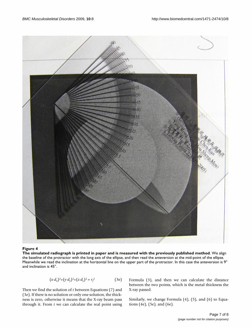
The simulated radiograph is printed in paper and is measured with the previously published methodFigure 4The simulated radiograph is printed in paper and is measured with the previously published method. We align the baseline of the protractor with the long axis of the ellipse, and then read the anteversion at the mid-point of the ellipse. Meanwhile we read the inclination at the horizontal line on the upper part of the protractor. In this case the anteversion is 9° and inclination is 45°.
Page 7 of 8(page number not for citation purposes)

BMC Musculoskeletal Disorders 2009, 10:8 http://www.biomedcentral.com/1471-2474/10/8
x2+y2+z2 = rao2 (4e)
x2+y2+z2 = rio2 (5e)
ax+by+cz = 0 (6e)
Then we find the solution of t between Equations (7) and(4e). If there is no solution or only one solution, the thick-ness is zero, otherwise it means that the X-ray beam passthrough it. We keep the solutions of t in the solution set.Similarly, we find the solution of t from Equations (7)and (5e). Then we keep the solutions of t in the solutionset if there are solutions.
We solve t from Equation (7) and Formula (6) and get therange of t, i.e. t>rx or t<rx, and rx is the solution of t fromEquations (7) and (6e).
We exclude the solutions in the solution set outside therange of t. If the number of solutions in the solution set isodd, we append rx into the set.
Now we sort the solutions in the set, and pair the solu-tions with their neighborhood. We apply these paired tsolutions to Equation (7) and get pairs of points.
Finally we add the distance of these pair points to we pre-viously calculated distance intra-head. The sum is the totalthickness the X-ray beam passed through the metal.
Additional material
AcknowledgementsWe thank United Orthopedic Corporation, Hsinchu, Taiwan for providing us technical data of U2 total hip arthroplasty.
This study was supported by the grant of NSC96-2320-B-087-001, Taiwan, ROC.
References1. Liaw CK, et al.: A new tool for measuring cup orientation in
total hip arthroplasties from plain radiographs. Clin OrthopRelat Res 2006, 451:134-9.
2. Fabeck L, et al.: A method to measure acetabular cup antever-sion after total hip replacement. Acta Orthop Belg 1999,65(4):485-91.
3. Ackland MK, Bourne WB, Uhthoff HK: Anteversion of the acetab-ular cup. Measurement of angle after total hip replacement.J Bone Joint Surg Br 1986, 68(3):409-13.
4. Pradhan R: Planar anteversion of the acetabular cup as deter-mined from plain anteroposterior radiographs. J Bone JointSurg Br 1999, 81(3):431-5.
5. Visser JD, Konings JG: A new method for measuring anglesafter total hip arthroplasty. A study of the acetabular cupand femoral component. J Bone Joint Surg Br 1981, 63B(4):556-9.
6. Widmer KH: A simplified method to determine acetabularcup anteversion from plain radiographs. J Arthroplasty 2004,19(3):387-90.
7. Ebramzadeh E, et al.: Accuracy of measurement of polyethylenewear with use of radiographs of total hip replacements. JBone Joint Surg Am 2003, 85-A(12):2378-84.
8. Livermore J, Ilstrup D, Morrey B: Effect of femoral head size onwear of the polyethylene acetabular component. J Bone JointSurg Am 1990, 72(4):518-28.
9. Hardinge K, et al.: Measurement of hip prostheses using imageanalysis. The maxima hip technique. J Bone Joint Surg Br 1991,73(5):724-8.
10. Shaver SM, et al.: Digital edge-detection measurement of poly-ethylene wear after total hip arthroplasty. J Bone Joint Surg Am1997, 79(5):690-700.
11. Martell JM, Berdia S: Determination of polyethylene wear intotal hip replacements with use of digital radiographs. J BoneJoint Surg Am 1997, 79(11):1635-41.
12. Collier MB, et al.: Evaluation of contemporary software meth-ods used to quantify polyethylene wear after total hiparthroplasty. J Bone Joint Surg Am 2003, 85-A(12):2410-8.
13. Devane PA, et al.: Measurement of polyethylene wear in metal-backed acetabular cups. I. Three-dimensional technique. ClinOrthop Relat Res 1995:303-16.
14. Geerdink CH, et al.: The determination of linear and angularpenetration of the femoral head into the acetabular compo-nent as an assessment of wear in total hip replacement: ACOMPARISON OF FOUR COMPUTER-ASSISTED METH-ODS. J Bone Joint Surg Br 2008, 90(7):839-46.
15. Calhoun PS, et al.: Three-dimensional volume rendering of spi-ral CT data: theory and method. Radiographics 1999,19(3):745-64.
16. Muniyandi M, et al.: Real-time PC based X-ray simulation forinterventional radiology training. Stud Health Technol Inform2003, 94:233-9.
17. Liaw CK, et al.: A simple mathematical standardized measure-ment of acetabulum anteversion after total hip arthroplasty.Computational and Mathematical Methods in Medicine 2008,9(2):105-119.
18. Liaw CK, et al.: Automatic digital PE wear measurement. AAOSannual meeting. Washington 2005.
19. Kosak R, et al.: Polyethylene wear in total hip prostheses: theinfluence of direction of linear wear on volumetric weardetermined from radiographic data. Skeletal Radiol 2003,32(12):679-86.
Pre-publication historyThe pre-publication history for this paper can be accessedhere:
http://www.biomedcentral.com/1471-2474/10/8/prepub
Additional File 1THR Simulator. The main program of our software.Click here for file[http://www.biomedcentral.com/content/supplementary/1471-2474-10-8-S1.exe]
Additional File 2Borland dynamic library #1. The dynamic library provided by Borland company.Click here for file[http://www.biomedcentral.com/content/supplementary/1471-2474-10-8-S2.dll]
Additional File 3Borland dynamic library #2. The dynamic library provided by Borland company.Click here for file[http://www.biomedcentral.com/content/supplementary/1471-2474-10-8-S3.dll]
Page 8 of 8(page number not for citation purposes)