bluetooth smart module - silabs.com · wake up pin functionality added defrag tag added for running...
TRANSCRIPT

BLUETOOTH SMART MODULE
CONFIGURATION GUIDE
Friday, 7 December 2018
Version 3.12

Silicon Labs Page of 3 43
Table of Contents
1 Version History ________________________________________________________________________ 42 Introduction ___________________________________________________________________________ 63 Project Configuration File ________________________________________________________________ 7
3.1 <device> _________________________________________________________________________ 73.2 <gatt> ___________________________________________________________________________ 83.3 <hardware> ______________________________________________________________________ 93.4 <config> _________________________________________________________________________ 93.5 <script> __________________________________________________________________________ 93.6 <usb_main> ______________________________________________________________________ 93.7 <image> ________________________________________________________________________ 103.8 <ota> __________________________________________________________________________ 103.9 <boot> _________________________________________________________________________ 113.10 Examples ______________________________________________________________________ 12
4 Hardware Configuration File (hardware.xml) _________________________________________________ 134.1 <sleeposc> ______________________________________________________________________ 134.2 <i2c_clock> ______________________________________________________________________ 144.3 <script> _________________________________________________________________________ 154.4 <slow_clock> ____________________________________________________________________ 154.5 <lock_debug> ____________________________________________________________________ 164.6 <sleep> _________________________________________________________________________ 164.7 <wakeup_pin> ___________________________________________________________________ 184.8 <host_wakeup_pin> _______________________________________________________________ 204.9 <txpower> _______________________________________________________________________ 214.10 <pmux> ________________________________________________________________________ 224.11 <port> _________________________________________________________________________ 234.12 <usb> _________________________________________________________________________ 244.13 <usart> ________________________________________________________________________ 254.14 <timer_ticks> ___________________________________________________________________ 294.15 <timer> ________________________________________________________________________ 304.16 <uartboot> _____________________________________________________________________ 324.17 <otaboot> ______________________________________________________________________ 354.18 Endpoints ______________________________________________________________________ 364.19 Examples ______________________________________________________________________ 36
5 Application Configuration File (config.xml) __________________________________________________ 375.1 <connections> ___________________________________________________________________ 375.2 <defrag> ________________________________________________________________________ 375.3 <manual_confirm> ________________________________________________________________ 385.4 <script_timeout> __________________________________________________________________ 385.5 <throughput> ____________________________________________________________________ 405.6 <passkey> ______________________________________________________________________ 405.7 <user_data> _____________________________________________________________________ 415.8 <watchdog> _____________________________________________________________________ 415.9 <dfu> __________________________________________________________________________ 415.10 <scriptstack> ___________________________________________________________________ 425.11 Examples ______________________________________________________________________ 42

Silicon Labs Page of 4 43
1 Version History
Version Comments
3.0 This document is separated from the Profile Toolkit Developer Guide document.
Compatibility changes for the Bluetooth Smart Software v.1.2 added:
Added BLE113 reference for <txpower> in hardware.xmlAdded fixed passkey documentation to config.xmlBootloader definition added for OTA update.USB interface is disabled by defaultDefault maximum power mode defined to be 3Wake up pin functionality addedDefrag tag added for running the defragmentation automatically in the boot-up.
In addition, editorial improvements done within the document.
3.1 Improved examples and configuration option descriptions.
3.2 Compatibility changes for the Bluetooth Smart Software v.1.2.2:
256kB variant configuration supported added for BLE113Binary image and memory configurability added for OTA SW update under the <ota> and <otaboot> tags
3.3 Improved examples
3.5 Compatibility changes for the Bluetooth Smart Software v.1.3.0:
Hardware configuration and TX power parts added for BLE121LR product variantOTA firmware update instructions added to create an OTA file just containing the BGScript and GATT portions
3.6 Compatibility changes for the Bluetooth Smart Software v.1.3.1:
<DFU> tag introduced for allowing that DFU boot-mode is not allowed.
3.7 Setup of Uart DFU bootloader interface option added:
<uartboot> tag introduced, allows to configure settings for UART that is used in Uart DFU Bootloader
3.8 Removed information about required <pmux regulator_pin="7" /> entry in hardware.xml when BLE121LR is used. Since v1.4.2 thisentry is not required any more (this configuration is now done automatically by BGBuild).
3.9 Added note about DFU baud rate configuration into <usart> section.
3.10 Corrected description of option in <uartboot> section.alternate
3.11 Added description of attribute.maxfwsizeUpdated description of attribute.ppm
Silicon Labs Page of 5 43
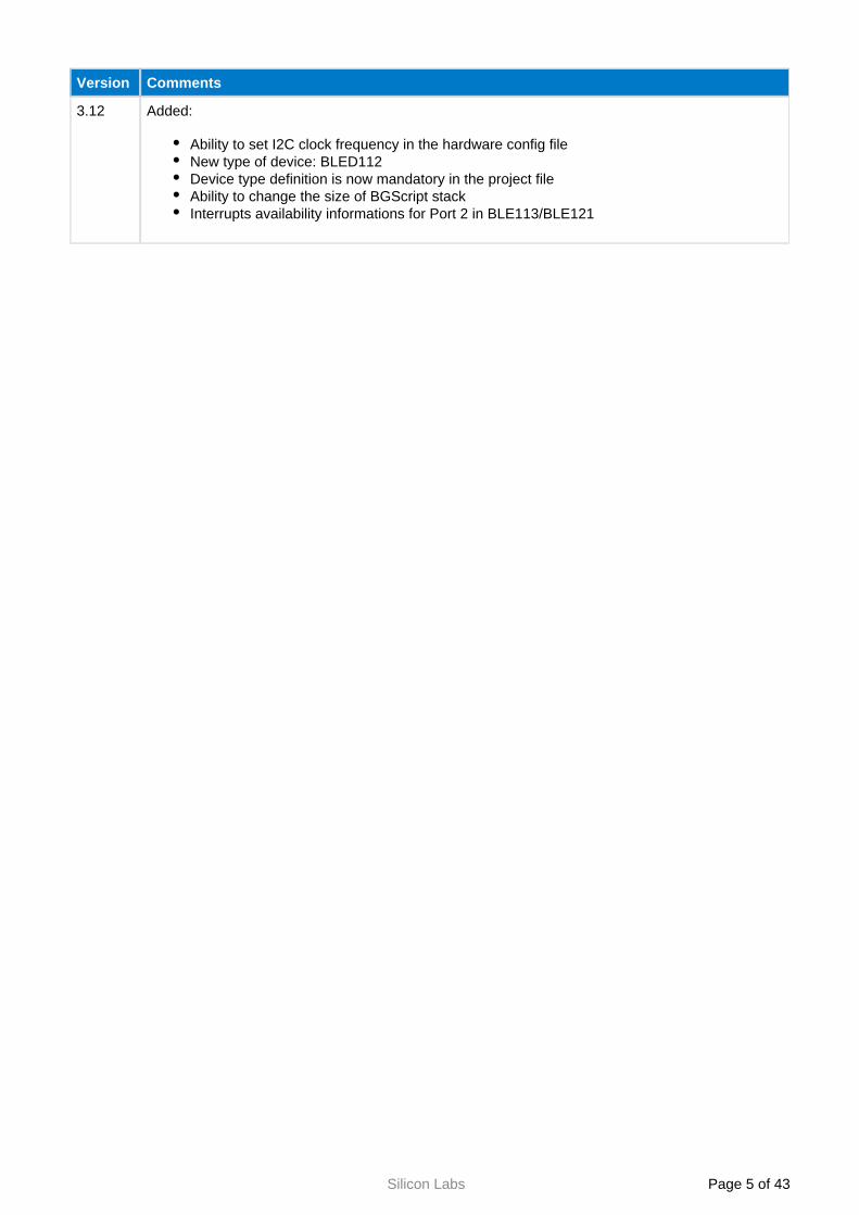
Version Comments
3.12 Added:
Ability to set I2C clock frequency in the hardware config fileNew type of device: BLED112Device type definition is now mandatory in the project fileAbility to change the size of BGScript stackInterrupts availability informations for Port 2 in BLE113/BLE121

Silicon Labs Page of 6 43
2 Introduction
The Smart configuration guide instructs you how to create a project file for your application and how Bluetoothto configure your Smart Modules hardware and application configuration settings.Bluetooth

Silicon Labs Page of 7 43
3 Project Configuration File
The project file (typically is the file that describes all the components included in project.bgproj or project.xml)a Bluetooth Smart software and hardware project. Typically these files are name something like this:
hardware.xml - Hardware configuration filegatt.xml - GATT database fileconfig.xml - Optional application configuration filescript.bgs - Optional BGScript application source codecdc.xml - Optional USB descriptor file (not used with BLE113, BLE121LR)
The project file also defines other features of the project like the hardware version (BLE112, BLED112, BLE113, and BLE121LR), firmware output files and selected bootloader.
The project file itself is a simple XML file with only few tags on it, which are described below.
If the project file is named as (or any other file with a extension), then the project.bgproj .bgprojBluegiga application will automatically recognize it in the Windows Explorer interface and BLE Updateallow you to easily open, compile, and flash the project to a module using the CC debugger.
3.1 <device>
Hardware type configuration
XML tag Description
type This tag is mandatory and defines the type of your Smart ModuleBluetooth
Options:
ble112: Use if you have BLE112
bled112: Use if you have BLED112
ble113: Use if you have BLE113
ble113-m256k: Use if you have BLE113-M256K
ble121lr-m256k: Use if you have BLE121LR longrange module
maxfwsize This tag defines size of memory in pages reserved for firmware (bootloader and stack). This parameter allows upload bigger images by OTA dfu in the future.
It could be also used in CSDK debug and release configurations, where bgbuild does not calculate firmware size and sets it to default 48 pages, if maxfwsize parameter is not used.
Default: it is set to value calculated by bgbuild, but with minimum 48 pages (96 kB) size.
Example: Defining device type BLE112
<device type="ble112" />
Example: Defining device type BLE113 (128kB flash variant)
<device type="ble113" />
Example: Defining device type BLE113 (256kB flash variant)
<device type="ble113-m256k" />

Silicon Labs Page of 8 43
1.
2.
XML tag Description
Example: Defining device type BLE112 with 112 kB (56 pages) firmware size
<device type="ble112" maxfwsize="56" />
The following steps need to be performed to do OTA with firmware size bigger than current maxfwsize parameter value (e.g. situation, when maxfwsize is set to 48, but new OTA image counts 51 pages):
Run OTA of image, which has no firmware (or with firmware size not bigger than current maxfwsize), but with maxfwsize parameter changed to new bigger value (i.e. value sufficient for bigger image size).Run OTA with new, bigger image. Now (after step 1) it could be successfully done, because maxfwsize parameter value has changed to sufficient level.
3.2 <gatt>
GATT database file
XML tag Description
in This tag points to the XML file that contains the GATT database structure.
Example: Defining the GATT database file
<gatt in="gatt.xml" />

Silicon Labs Page of 9 43
3.3 <hardware>
Hardware configuration file
XML tag
Description
in This tag points to the XML file which contains the hardware configuration for your Bluegiga BluetoothSmart device.
Example: Defining the hardware configuration file
<hardware in="hardware.xml" />
3.4 <config>
Application configuration file (optional)
XML tag
Description
in This tag points to the XML file which contains the generic application configuration of your Bluegiga Smart device.Bluetooth
Example: Defining the application configuration file
<config in="config.xml" />
3.5 <script>
BGScript application file (optional)
XML tag
Description
in This tag points to the BGScript file that contains the BGScript source code for your standalone Smart application.Bluetooth
If you use the BGAPI protocol and a separate host (which cannot be used simultaneously with BGScript code), then this tag should be left out.
Example: Defining the BGScript file
<script in="script.bgs" />
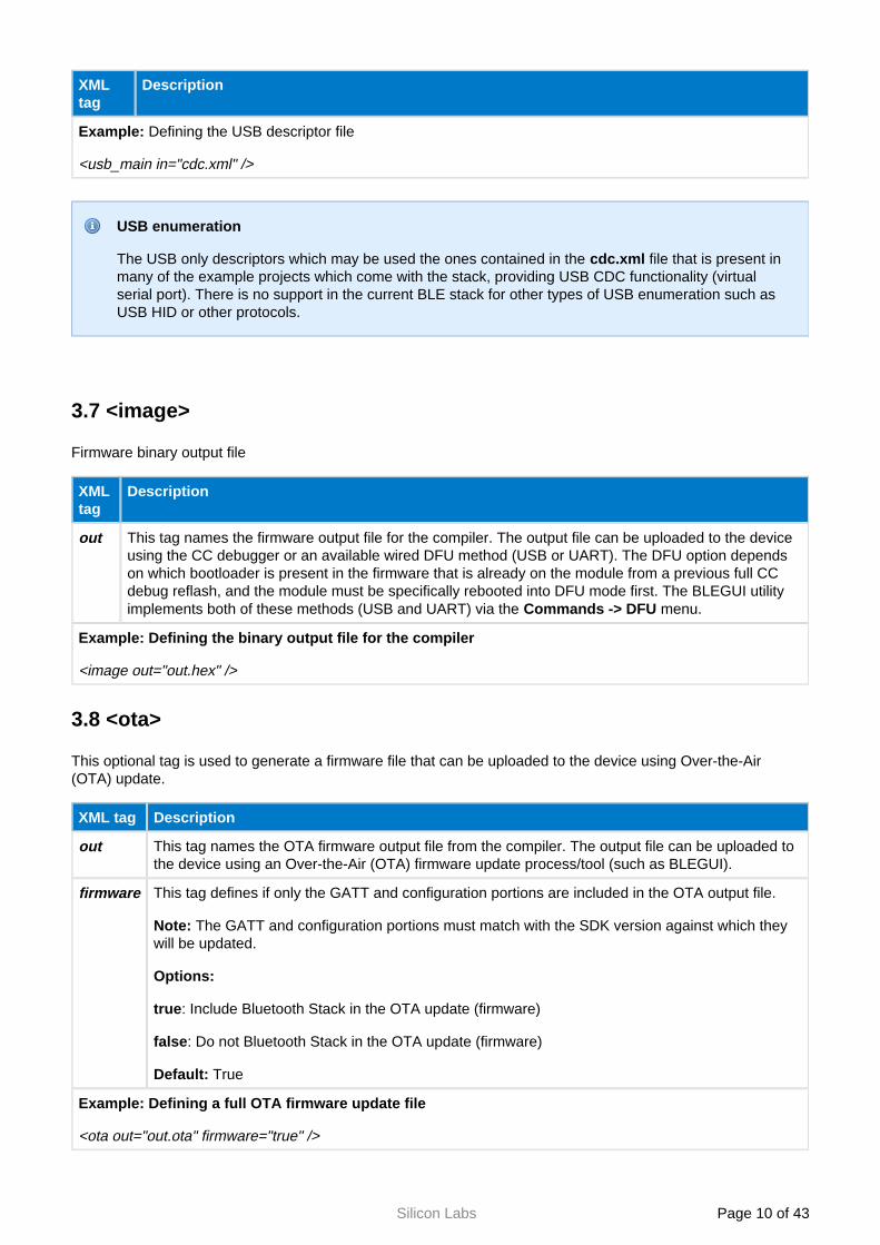
3.6 <usb_main>
USB descriptor definition (optional)
XML tag
Description
in This tag points to the XML file that contains the USB descriptor for BLED112 or BLE112 BluetoothSmart devices.If USB interface is disabled in the hardware configuration, this tag is not needed.
Silicon Labs Page of 10 43
XML tag
Description
Example: Defining the USB descriptor file
<usb_main in="cdc.xml" />
USB enumeration
The USB only descriptors which may be used the ones contained in the file that is present in cdc.xmlmany of the example projects which come with the stack, providing USB CDC functionality (virtual serial port). There is no support in the current BLE stack for other types of USB enumeration such as USB HID or other protocols.
3.7 <image>
Firmware binary output file
XML tag
Description
out This tag names the firmware output file for the compiler. The output file can be uploaded to the device using the CC debugger or an available wired DFU method (USB or UART). The DFU option depends on which bootloader is present in the firmware that is already on the module from a previous full CC debug reflash, and the module must be specifically rebooted into DFU mode first. The BLEGUI utility implements both of these methods (USB and UART) via the menu.Commands -> DFU
Example: Defining the binary output file for the compiler
<image out="out.hex" />
3.8 <ota>
This optional tag is used to generate a firmware file that can be uploaded to the device using Over-the-Air (OTA) update.
XML tag Description
out This tag names the OTA firmware output file from the compiler. The output file can be uploaded to the device using an Over-the-Air (OTA) firmware update process/tool (such as BLEGUI).
firmware This tag defines if only the GATT and configuration portions are included in the OTA output file.
Note: The GATT and configuration portions must match with the SDK version against which they will be updated.
Options:
true: Include Bluetooth Stack in the OTA update (firmware)
false: Do not Bluetooth Stack in the OTA update (firmware)
Default: True
Example: Defining a full OTA firmware update file
<ota out="out.ota" firmware="true" />

Silicon Labs Page of 11 43
XML tag Description
Example: Defining an OTA firmware update file containing just BGScript and GATT database
<ota out="out.ota" firmware="false" />
3.9 <boot>
Selects the bootloader interface used for In-the-Field or Over-the-Air firmware updates.
XML tag
Description
fw This tag is used to describe the boot loader used in the firmware. The boot loader also devices which interface is used for the on-the-field firmware updates.Only one bootloader can be active in the device.
Options:
boot: Configures the bootloader for the USB interface. Use only with the BLE112 module or BLED112 dongle.
bootuart: Configures the bootloader for the UART interface.
bootota: Configures the bootloader for Over-the-Air (OTA) interface.
Default:
boot
Example: Enabling UART bootloader
<boot fw="bootuart" />
Example: Enabling USB boot loader
<boot fw="boot" />
Example: Enabling OTA boot loader
<boot fw="bootota" />
If UART bootloader is enabled proper uart port interface for bootloader must be <boot fw="bootuart" /> set in hardware.xml file (attribute: < uartboot />)

Silicon Labs Page of 12 43
3.10 Examples
Below is an example of a project file for BLE112 Bluetooth Smart Module or BLED112 USB dongle using USB interface:
BLE112 Project
<?xml version="1.0" encoding="UTF-8" ?><project> <gatt in="gatt.xml" /> <hardware in="hardware.xml" /> <usb_main in="cdc.xml" /> <config in="config.xml" /> <device type="ble112" /> <boot fw="boot" /> <image out="BLE112_usbcdc.hex" /></project>
Below is an example of a project file for BLE113 Bluetooth Smart Module using UART interface for potential DFU updates:
BLE113 Project
<?xml version="1.0" encoding="UTF-8" ?><project> <gatt in="gatt.xml" /> <hardware in="hardware.xml" /> <config in="config.xml" /> <device type="ble113" /> <boot fw="bootuart" /> <image out="BLE113.hex" /></project>
Below is an example of a project file for BLE113 Bluetooth Smart Module running a BGScript application and OTA bootloader:
BLE113 Project
<?xml version="1.0" encoding="UTF-8" ?><project> <gatt in="gatt.xml" /> <hardware in="hardware.xml" /> <config in="config.xml" /> <device type="ble113" /> <boot fw="bootota" /> <image out="BLE113.hex" /></project>

Silicon Labs Page of 13 43
4 Hardware Configuration File (hardware.xml)
The hardware configuration file is used to configure the hardware features such as TX power, UART, SPI, hardware timers, and GPIO settings of your Bluegiga Smart device.Bluetooth
4.1 <sleeposc>
Sleep oscillator settings
Attribute Value - Description
enable This setting can be used to enable or disable the external sleep clock.
Options:
true: This enables the external 32.7680KHz sleep oscillator. This sleep oscillator allows the BLE112, BLE113, or BLE121LR to enter power mode 1 or 2 whenever radio is not active, transmitting or receiving, for example also during radio silence between connection intervals.
false: This disables the external 32.7680KHz sleep oscillator, so the TI's chipset internal 32.7530KHz RC oscillator is used for timings. Using this setting increases current consumption because power modes 1 and 2 are prevented during any activity (connection - scanning - Bluetoothadvertising), due to limited accuracy of internal RC oscillator.
Default:
false
Note:
In BLE112, BLE113, and BLE121LR this options MUST be configured to enable the external sleep oscillator, while in the BLED112 this option MUST be set to "false", since the USB dongle does not contain the required external oscillator. Setting this option to "true" with device type set to "BLED112" will result in a compilation error in BGBuild.
ppm This setting defines the sleep clock accuracy used to calculate window widening. Increasing this value may improve connection stability in extreme temperature conditions, but also may have negative influence on current consumption.
Options:
31-500
Default:
50
Note:
Value of ppm is rounded up to levels specified by Bluetooth: 50 ppm, 75 ppm, 100 ppm, 150 ppm, 250 ppm, 500 ppm.
Example : Configuration for BLE112, BLE113, BLE121LR Smart Modules: Bluetooth
<sleeposc enable="true" ppm="50" />
Example : Configuration for BLED112 USB dongle:
<sleeposc enable="false" ppm="50" />

Silicon Labs Page of 14 43
4.2 <i2c_clock>
I2C clock frequency value
Attribute Value - Description
freq This setting can be used to set a value of the clock frequency for I2C communication interface. Values are given in kHz.
BLE112 module uses bit-bang method so the clock rate is approximately 20-25 kHz and it does vary slightly because other functionality has higher interrupt priority, such as the BLE radio. Therefore this option is not valid for BLE112/BLED112 module.
Options:
123: sets the I2C clock frequency to 123 kHz
144: sets the I2C clock frequency to 144 kHz
165: sets the I2C clock frequency to 165 kHz
197: sets the I2C clock frequency to 197 kHz
33: sets the I2C clock frequency to 33 kHz
267: sets the I2C clock frequency to 267kHz
533: sets the I2C clock frequency to 533 kHz
Default:
267
Example: Setting clock frequency value
<i2c_clock freq="123" />

Silicon Labs Page of 15 43
4.3 <script>
BGScript settings
Attribute Value - Description
enable This setting can be used to enable or disable BGScript application execution.
Options:
true: BGScript application and VM are enabled.
false: BGScript application and VM are disabled and BGAPI should be used instead.
Default:
false
Example: Enable scripting
<script enable="true" />
4.4 <slow_clock>
This setting can be used to slow the system clock from 32MHz to 250KHz when radio is active, in order to reduce the peak power consumption. The average current consumption reduction between normal clock speed and slow clock speed is approximately 5-6 mA.
Attribute Value - Description
enable Options:
true: System clock is slowed down.
false: System clock is not slowed down.
Default:
false
Example: Enable slow clock
<slow_clock enable="true" />
UART and PWM interfaces use system clock for timings. If the system clock is allowed to slow down (notice that it will happen only when radio is active) the peripheral interface timings become variable, thus invalid. This feature must only be enabled when peripherals requiring stable clock are not used.
SPI Master sends clock signal with transmission which allows enabling the slow clock feature.
Due to hardware limitation, CPU may not have enough time to switch between speed of the system clock if the switching itself is performed very fast.

Silicon Labs Page of 16 43
4.5 <lock_debug>
This feature can be used to lock down the debug interface (CC debugger interface, P2_1/P2_2) on the BLE112, BLE113, and BLE121LR Smart Modules in order to protect application code and data. If this feature Bluetoothis enabled, then only a of the firmware can be done with the CC debugger using the TI's Smart RF full eraseFlash Programmer. Notice that Bluegiga's own re-flash tool would not be usable anymore, and for instance it would become impossible to retrieve the serial number and license key of a module.
Attribute Value - Description
enable Options:
true: Debug interface is locked.
false: Debug interface is available.
Default:
false
Example: Lock debug interface
<lock_debug enable="true" />
4.6 <sleep>
This setting can be used to enable or disable sleep modes.
Attribute Value - Description
enable Options:
true: All power modes can be enabled. Selection of power modes is done automatically by the firmware. Firmware will select the best power saving mode automatically to achieve lowest possible power consumption.
false: Use this to prevent the firmware from entering any of the sleep modes.
Default:
true
max_mode Maximum power mode device is allowed to use.
Range:
1-3
Default:
3
Example : Allow power modes 1 and 2 and disable power mode 3.
<sleep enable="true" max_mode="2" />

Silicon Labs Page of 17 43
When sleep mode (power mode 1, 2, or 3) is enabled and the module is not kept awake (for example by using the wake-up pin), then the Smart module to any BGAPI Bluetooth will not respondcommands or process any other incoming sent to it via UART. If you want to enable sleep mode and use the UART interface to communicate with the module, you need to enable the wake-up pin feature (described below) and provide a wake-up signal from an external host.

Silicon Labs Page of 18 43
1. 2.
3. 4.
4.7 <wakeup_pin>
This feature is used to prevent the Smart module from entering any sleep modes like power mode 3, Bluetoothor alternatively used to to wake it up if it has entered a low power mode. If you use UART to communicate with the module, then you need to enable this feature and assert the relevant pin before sending any streaming data or BGAPI commands to the module, and keep it asserted until the last byte has been clocked into the module over the UART RX pin.
The wake-up pin functionality can only be assigned to a single GPIO, but you can still assign normal GPIO interrupts to other pins using BGAPI/BGScript commands. The difference between this special wake-up pin operation and normal GPIO interrupts is that this pin will not only generate the interrupt which wakes the module, but will also keep the module awake as long as it is held in the asserted state. Normal GPIO interrupts can wake the module from any state (even power mode 3), but after the interrupt event handler completes, the module will return to sleep (if sleep is enabled and not prevented via the wake-up pin).
The correct procedure for using the wake-up pin to send BGAPI packets over UART is as follows:
Assert the wake-up pin from an external hostProcess the " " BGAPI event packet which is generated and sent out the hardware_io_port_statusmodule's TX pinSend the desired BGAPI command packet to the moduleWait until you receive before de-asserting the at least the first byte of the BGAPI response packetwake-up pin
Important:
Step 2 above is critical because some sent data may be ignored if you do not process the port status event before starting to send data.Step 4 above is critical because if you de-assert the wake-up pin too soon (e.g. immediately after the last byte is placed in the TX buffer of the attached UART host), then the last byte or two may not be properly clocked into the module before it goes to sleep again, resulting in lost or corrupt data.
attribute description
enable Used to enable wake-up pin feature. Wake-up pin wakes the device up from a sleep mode or prevents it from entering it again.
Options:
true: wake-up pin is enabled
false: wake-up pin is disabled
port Defines the port where wake-up pin is.
Options:
0-2
Option port="2' is available only for BLE113 and BLE121LR.
pin Defines the pin inside the selected port.
Options:
0-7
For Port 2 in BLE113 and BLE121LR only options pin="0" and pin="1" are available.

Silicon Labs Page of 19 43
attribute description
state Logic state for wake-up pin.
Options:
up
down
Default:
up
Example: Enabling wake-up on P0_0
<wakeup_pin enable="true" port="0" pin="0" state="up" />
When this pin is pulled, the Smart module does not enter any sleep modes which increases Bluetoothpower consumption.
When this pin is used to wake up the Smart module from sleep mode, a Bluetooth API event is triggered immediately, since it's handled as a normal GPIO hardware_io_port_status
interrupt. You should expect this event to occur and either handle it or ignore it intentionally if you are using external control via the BGAPI protocol.

Silicon Labs Page of 20 43
4.8 <host_wakeup_pin>
This pin can be used to wake up an external host from sleep when the Smart module has data to Bluetoothsend over the UART interface. The external host should then use flow control signals (or wake immediately) so that the module can send data to it.
Notice that the host wake-up pin is only meant to wake up the host from a sleep mode and it does not necessarily remain active during the UART transmission. The host therefore should not go back to sleep after the host wake-up pin is de-asserted, but only after all the expected data has been received over UART.
attribute description
enable Use to enable the host wake-up pin feature. Host wake-up pin is asserted when the BluetoothSmart module has data to send.
Options:
true: host wake-up pin is enabled
false: host wake-up pin is disabled
port Defines the port used for the host wake-up.
Options:
0-2
Option port="2' is available only for BLE113 and BLE121LR.
pin Defines the pin inside the selected port.
Options:
0-7
For Port 2 in BLE113 and BLE121LR only options pin="0" and pin="1" are available.
state Logic state for host wake-up signal.
Options:
up
down
Default:
up
Example:
Example: Enabling wake-up on P1_1
<host_wakeup_pin enable="true" port="1" pin="1" state="up" />

Silicon Labs Page of 21 43
4.9 <txpower>
This can be used to configure the TX output power used since boot. Values represent roughly equal linear divisions between the minimum and maximum output power as noted in the attribute description.power
Attribute Value - Description
power Default TX power setting
Range:
0-15
BLE112 (BLED112): 15 is the highest TX power setting and equals roughly to 3dBm (0dBm), while 0 is the lowest value and corresponds to around -24dBm.
BLE113: 14 is the highest TX power setting and equals roughly to +0dBm, while 0 is the lowest value and corresponds to around -24dBm.
BLE121LR: 9 is the highest TX power setting and equals roughly to +8dBm, while 0 is the lowest value and corresponds to around -10dBm.
Using a value of 15 with the BLE113, or using any value between 10 and 15 with the BLE121LR, is the same as using respectively their max values of 14 or 9.
bias TX power amplifier bias setting. Do not modify.
Options:
5
Example: BLE112 with +3 dBm TX power<txpower power="15" bias="5" />
Example: BLE112 with 0 dBm TX power<txpower power="13" bias="5" />
Example: BLE113 with 0 dBm TX power<txpower power="15" bias="5" />

Silicon Labs Page of 22 43
4.10 <pmux>
This setting is used to configure the control pin for an external DC/DC converter which can be used to reduce the peak TX and RX power consumption. A GPIO pin needs to be dedicated to control the DC/DC converter's
or modes. Any GPIO pin from Port 1 can be dedicated as the DC/DC control pin and the enable bypassfirmware will automatically control the pin depending on the Bluetooth transmission and reception states.
The BLE development kits contain an external DC/DC converter which is specifically designed to work with the internal CC254x radio chipset. When the GPIO pin defined with is high, the DC/DC converter is <pmux>enabled, and when the GPIO pin is low, the converter is disabled. Note that the circuit is design to the disable converter at all times except when the radio is active. By doing this, the input voltage is dropped to 2.1V only when the radio is on and the resulting current consumption is less during transmissions. This is particularly beneficial because of the battery chemistry of most small coin cells. The reduced current draw during transmissions will notably extend the life of a typical CR2032 cell.
attribute description
regulator_pin Defines the output pin for the external DC/DC converter in Port 1.
Range:
0-7
Note:
Only pins of can be used to control the DC/DC converter.Port 1
With the BLE121LR this must be selected for pin P1_7 which is used to control the internal power amplifier on the module
clock_pin Defines the output pin in Port 0 for a 32.768 kHz clock signal, which can be used to provide the clock value to external devices.
Range:
0-7
Note:
Only can be used for clock signal output.Port 0
Example: This is for DKBLE112 and DKBLE113 with DC/DC control on P1_7 and no clock signal in use
<pmux regulator_pin="7" />
Due to hardware limitation, stable logic state of the PMUX pin may not change if the switching itself is performed very fast.

Silicon Labs Page of 23 43
4.11 <port>
This setting is used for the I/O port configuration settings (input only).
attribute description
index Port index to configure
Range:
0-2
tristatemask Tristate configuration (bit mask) for port. For the pins defined with this bit mask, no high/low pull will be used, but the pins will be in tristate mode.
Range:
0x00 - 0xFF
For example 0x02 means pin number 1 is configured to be tristated instead of being pulled high/low.
pull Defines the pull direction.
Options:
up: Pins are pulled up
down: Pins are pulled down
Note:
The pull direction will affect the whole port and and individual pin directions cannot be configured.
Example : pulling all pins in Port 0 down
<port index="0" tristatemask="0" pull="down" />
By default all the ports except P1_0 and P1_1 are configured as inputs with pull-ups. P1_0 and P1_1 should be configured as outputs or pulled up externally.
All unused I/O pins should have a defined level and should not be left floating. This can be done by leaving the pin unconnected and by configuring the pin as a general-purpose I/O input with a pull-up resistor. Alternatively the pins can be configured as a general-purpose I/O output. In either case, the pins should not be connected directly to VDD or GND, in order to avoid excessive power consumption.
Port 2 pins do not support interrupts in BLE112 and BLED112. They may still be pulled up or down with the above configuration in hardware.xml.
For Port 2 in BLE113 and BLE121LR only pins 0 and 1 are available for interrupts.
All pins in Port 0 and 1 support interrupts.

Silicon Labs Page of 24 43
4.12 <usb>
USB interface settings:
Attribute Value - Description
enable Enables or disables the USB interface.
Options:
true: Use this to enable the USB interface.
false: Use this to disable the USB interface.
Default:
false
endpoint Configures the USB interface usage purpose.
Options:
none: USB can be controller with a BGScript application
api: USB is used for the BGAPI protocol
test: See endpoint section for more information
script: do not use
usb: See endpoint section for more information
uart0: See endpoint section for more information
uart1: See endpoint section for more information
See: Endpoints available below.
Example : Enabling BGAPI over USB<usb enable="true" endpoint="api" />
Example : Enabling USB access for BGScript<usb enable="true" endpoint="none" />
In the BLED112, the interface must always be enabled or the dongle becomes non-communicative, resulting in a potentially bricked device.In the BLE112, this should be set to false, unless the interface is really needed, since USB constantly uses 5+ mA of current.In the BLE113 and BLE121LR, this must always be set to false, since this module does not have a USB interface.

Silicon Labs Page of 25 43
4.13 <usart>
This setting is used to configure the USART interface of the BLE112, BLE113, or BLE121LR Smart Bluetoothmodules.
In UART mode, the number of data bits is 8 and parity is set to none. Number of data bits and parity cannot be reconfigured.
attribute description
channel USART channel to configure
Options:
0: USART channel 0
1: USART channel 1
baud USART baudrate and SPI master clock.
Range:
1200 - 2000000
alternate Alternate configuration option for USART.
Options:
1: Alternative configuration 1 (see data sheet for details)
2: Alternative configuration 2 (see data sheet for details)
endpoint Configures the UART interface usage purpose.
Options:
none: USART interface can be controller with a BGScript application
api: USART is configured as the host interface making use of the BGAPI protocol
test: USART is in 2-wire UART direct test mode. See. "BT Core Vol 6 Part F: Direct Test Mode". USART must also be configured in UART mode and flow control disabled.
Note:
The BGAPI protocol is not available over the interface operating in SPI mode.

Silicon Labs Page of 26 43
attribute description
mode USART operation mode.
Options:
uart: USART is configured as UART interface. When BGAPI is used over UART in this mode, hardware flow control MUST be used.
packet: USART is configured as UART interface using the BGAPI packet mode. This allows BGAPI to be used over UART without hardware flow control.
spi_master: USART is configured as SPI master.
spi_slave: USART is configured as SPI slave. Not recommended to be used due to the SPI slave interface limitations (see below).
Default:
uart
Note:
See the BGAPI protocol description from the API reference manual for more information about the packet mode.
polarity SPI polarity configuration
Options:
positive: Configures the SPI clock polarity to be positive
negative: Configures the SPI clock polarity to be negative
Default:
negative
phase SPI clock phase
Options:
0
1
Default:
1
endianness SPI bit ordering
Options:
msb: most signigicant bit
lsb: least significant bit

Silicon Labs Page of 27 43
attribute description
flow UART flow control setting
Options:
true: Hardware flow control (RTS and CTS) enabled
false: Hardware flow control (RTS and CTS) disabled
Default:
true
stop UART stop bit logic
Options:
high
low
Default:
high
start UART start bit logic
Options:
high
low
Default:
low
Note:Must be different than stop bit logic.
stopbits UART stop bits
Options:
1: One stop bit
2: Two stop bits
Default:
1
Example : Enabling BGAPI over UART on DKBLE
<usart channel="1" alternate="1" baud="115200" endpoint="api" />
Example : Enabling UART access for BGScript on DKBLE
<usart channel="1" alternate="1" baud="115200" endpoint="none" />
Example : Enabling SPI master interface on DKBLE to control the display
<usart channel="0" mode="spi_master" alternate="2" polarity="positive" phase="1" endianness="msb" baud="57600" endpoint="none" />

Silicon Labs Page of 28 43
The DFU baud rate is independent from the baud rate configuration defined with <usart>. The UART baud rate configuration for DFU must be done with <uartboot> configuration.
SPI slave limitations
SPI slave limitations The Bluegiga BLE modules are really only practical as a SPI master. It has only a 1-byte hardware buffer in the USART which implements SPI functionality, and the BLE stack doesn't currently provide any methods for generating an API-level interrupt when there is new data coming in from the master (e.g. when the Slave Select pin is asserted or when data is clocked in). This means that SPI slave functionality requires constant polling and very slow data transfers. Additionally, there
, so even this very limited implementation is is no BGAPI control possible over the SPI interfaceonly usable with a BGScript-based application.

Silicon Labs Page of 29 43
4.14 <timer_ticks>
This configuration controls a global prescaler for Timer 1, Timer 3, and Timer 4. The prescaler value ( speedattribute) can be set to a value between 0.25 MHz to 32 MHz (while the system clock is fixed at 32 MHz, that is, when <slow_clock> is set to false).
This setting can be used to slow down the clock value to give to the timer and generate longer values when using for example PWM output signals.
attribute description
speed Timer tick settings.
Options:
0: 32 MHz: 16 MHz1: 8 MHz2: 4 MHz3: 2 MHz4: 1 MHz5: 500 kHz6: 250 kHz7
Example : 32 MHz timer<timer_ticks speed="0" />

Silicon Labs Page of 30 43
4.15 <timer>
This configuration is used to configure the hardware timer(s) of the BLE112/113 module. is reserved for Timer 2internal use by the BLE stack.
attribute description
index Timer index to configure.
Options:
1: Timer 1
3: Timer 3
4: Timer 4
enabled_channels Enabled channels for specified timer.
Range:
0x00 - 0xFF
divisor Divisor for specified timer .
Timer 1:
0: Tick frequency/1
1: Tick frequency/8
2: Tick frequency/32
3: Tick frequency/128
Timer 3 and Timer 4:
0: Tick frequency/1
1: Tick frequency/2
2: Tick frequency/4
3: Tick frequency/8
4: Tick frequency/16
5: Tick frequency/32
6: Tick frequency/64
7: Tick frequency/128

Silicon Labs Page of 31 43
attribute description
mode Operating mode for specified timer.
Timer 1:
0 : Suspended
1 : Free running
2 : Modulo
3 : Up/Down
Timer 3 and Timer 4:
0 : Free running
1 : Down
2 : Modulo
3 : Up/Down
alternate Alternate configuration for specified timer.
Options:
1: Alternative configuration 1 (see data sheet for details)
2: Alternative configuration 2 (see data sheet for details)
Example: 4-channel PWM configuration
<timer index="1" enabled_channels="0x1f" divisor="0" mode="2" alternate="2" />

Silicon Labs Page of 32 43
4.16 <uartboot>
This setting is used to configure the UART interface of the BLE112, BLE113, or BLE121LR Smart Bluetoothmodules that is used by UART DFU Bootloader.
The number of data bits is 8 and parity is set to none. Number of data bits and parity cannot be reconfigured.
attribute description
channel UART BOOT channel to configure
Options:
0: UART channel 0
1: UART channel 1
Default:
0
baud UART BOOT baudrate.
Range:
1200 - 2000000
Default:
57600
alternate Alternate configuration option for UART BOOT.
Options:
1: Alternative configuration 1 (see data sheet for details)
2: Alternative configuration 2 (see data sheet for details)
Default:
1
flow UART BOOT flow control setting
Options:
true: Hardware flow control (RTS and CTS) enabled
false: Hardware flow control (RTS and CTS) disabled
Default:
true

Silicon Labs Page of 33 43
attribute description
stop UART BOOT stop bit logic
Options:
high
low
Default:
high
start UART BOOT start bit logic
Options:
high
low
Default:
low
Note:Must be different than stop bit logic.
stopbits UART stop bits
Options:
1: One stop bit
2: Two stop bits
Default:
1
Example : Enabling UART for Uart DFU bootloader on DKBLE
<uartboot channel="1" alternate="1" baud="115200" />
Example : Enabling UART for Uart DFU bootloader on DKBLE
< channel="1" alternate="1" baud="115200" flow="true" stop="high" start="low" stopbits="1" />uartboot
Example : Enabling UART for Uart DFU bootloader on DKBLE when you want to use the same UART that is already configured*
<usart channel="1" alternate="1" baud="115200" endpoint="api" />
<uartboot channel="1" /> <!--the rest of settings is same as in uart interface above -->
Default values
If there is configured (enabled) any USART interface in UART Mode on the device, the default values of the UART for DFU Bootloader interface are inherited from the values of that interface.

Silicon Labs Page of 34 43
Enable UART Bootloader
To enable UART DFU Bootloader option, you need to enable bootuart mode by adding an attribute: <boot fw="bootuart" /> in .bgproj file of your project.

Silicon Labs Page of 35 43
4.17 <otaboot>
Bootloader configuration for Over-the-Air update.
attribute description
source Source where image is updated from.
Options:
external: External SPI flash memory is used
internal: Internal memory is used (requires 256kB internal flash module variant)
uart SPI USART channel to which external flash chip is connected.
Options:
0: USART channel 0
1: USART channel 1
cs_port Chip select port for SPI memory
Options:
0: Port 0
1: Port 1
cs_pin Chip select pin for SPI memory
Options:
0-7: Pin 0 to pin 7
power_port Power port for SPI memory
Options:
0: Port 0
1: Port 1
Note: P1_0 and P1_1 are recommended since they can provide high power output and can power the flash chip directly.
power_pin Power pin for SPI memory
Options:
0-7: Pin 0 to pin 7
Note: P1_0 and P1_1 are recommended since they can provide high power output and can power the flash chip directly.
Example: Enabling external SPI flash board on DKBLE
<otaboot source="external" uart="0" cs_port="1" cs_pin="2" power_port="1" power_pin="0" />

Silicon Labs Page of 36 43
4.18 Endpoints
The possible endpoint values used either for USB or UART are listed below:
Value description
none Data can be read from/written to BGScript when using command and system_endpoint_tx event in BGScript code.system_endpoint_rx
api Endpoint is connected to BGAPI protocol.
test Endpoint is connected to UART testing purposes.Bluetooth
script Do not use.
usb Endpoint is connected to USB interface.
uart0 Endpoint is connected to UART0 interface.
uart1 Endpoint is connected to UART1 interface.
4.19 Examples
Example for BLED112 USB dongle to enable BGAPI protocol over USB interface:
<?xml version="1.0" encoding="UTF-8" ?> <hardware> <txpower power="15" bias="5" /> <usb enable="true" endpoint="api" /> <sleeposc enable="false" ppm="30" /> </hardware>
Below is an example of hardware configuration file used with BLE112, BLE113 or BLE121LR module, which uses BGAPI protocol over UART on DKBLE and UART bootloader enabled . Also the DC/DC control pin is enabled to control the external DC/DC converter and the wake-up pin is enabled in P0_0 pin (button).
Never use the configuration below with a BLED112 USB dongle.
<?xml version="1.0" encoding="UTF-8" ?><hardware> <sleeposc enable="true" ppm="30" /> <usb enable="false" endpoint="none" /> <txpower power="15" bias="5" /> <usart channel="1" alternate="1" baud="115200" flow="true" endpoint="api" /> <uartboot channel="1" /> <wakeup_pin enable="true" port="0" pin="0" /> <port index="0" tristatemask="0" pull="down" /> <pmux regulator_pin="7" /></hardware>

Silicon Labs Page of 37 43
5 Application Configuration File (config.xml)
This application configuration file is used to configure some of the Smart Software's features such as Bluetooththe number of maximum connections. This file is optional.
5.1 <connections>
Defines the maximum number of connections that are supported by the firmware.
Attribute Value - Description
value Defines how many connections are supported. Affects how much RAM to reserve for connections.
Range:
1 - 8
Default:
1
Example : Enabling one (1) connection
<connections value="1" />
Example : Enabling eight (8) connections
<connections value="8" />
When more then one (1) connection is supported in the file, then connection interval config.xmlvalues (minimum and maximum) used in connection commands must be divisible by all connections* 2.5ms
Examples:
If three (3) connections are supported, then the connection interval range has to contain limit values that are divisible by = . In this case, any multiple value of can be used, such as 3 * 2.5ms 7.5ms 7.5ms
, , , , etc.7.5ms 15ms 22.5ms 30ms
Alternatively, if two (2) simultaneous connections are supported, the interval values must be divisible by . Notice that in this case, the lowest possible interval of cannot be used because it is not 5ms 7.5msdivisible by , so only larger connection intervals such as , , etc. can be used.5.0ms 10ms 15ms
If only one (1) connection is supported, then any connection interval can be used when issuing connection commands.
5.2 <defrag>
Defines whether the persistent store is defragmented automatically at boot time.
Attribute Value - Description

Silicon Labs Page of 38 43
Attribute Value - Description
enable Defragmentation enabled
Options:
true: Defragmentation run at boot
false: Defragmentation during boot disabled
Default:
true
5.3 <manual_confirm>
If this tag exists in the file, then manual confirmation of attribute indications will be enabled. config.xml Note and does not take any attributes.that it only needs to exist
When the Smart stack receives attribute indications from a remote device, it produces an Bluetooth event to the host, where the type is attclient_attribute_value
. The host (application) must respond to this event with the attclient_attribute_value_type_indicate_rsp_req command after it has properly handled the indication to acknowledge that the data attclient_indicate_confirm
has been received.
This feature can be used by the host software to acknowledge the indication data, and this provides extra reliability in some kinds of application. If this tag is not present, then the BLE stack will automatically acknowledge indications upon reception.
Attribute Value - Description
Enables or disables manual indication confirmations.
Example: Enabling manual confirmations
<manual_confirm />
5.4 <script_timeout>
Defines maximum number of steps (commands) a BGScript can run within an event before a is raised.system_script_failure
Attribute Value - Description
value Maximum number of steps a BGScript can take.
Range:
0 - 65535
Default:
1000
Example : disabling script timeout feature
<script_timeout value="0" />
Example : Limiting BGScript steps to 10000
<script_timeout value="10000" />

Silicon Labs Page of 39 43
This timeout is especially recommended to be used when developing BGScript applications into BLED112 USB dongle.

Silicon Labs Page of 40 43
5.5 <throughput>
Defines how data packets are sent over the air during each connection interval.
Attribute Value - Description
optimize Throughput optimization setting
Options:
power: Only a single packet is sent at each connection interval. This setting minimizes power consumption, but might limit throughput.
balanced: Sends only packets that fit in the transmission buffer, which is 128 bytes. Normally 3-4 packets will fit, depending on user payload and overhead.
performance: Maximizes throughput by loading new packets into transmission buffer and sending them as soon as the previous packets have been successfully transmitted. Increases power consumption.
Default:
balanced
Example : Optimizing data throughput
<throughput optimize="performance" />
Example : Optimizing power consumption
<throughput optimize="power" />
5.6 <passkey>
This configuration defines a fixed passkey to be used during MITM paring instead of a randomly generated passkey.
If this tag is not used, then the passkey for Man-in-the-Middle pairing will be randomly generated, as described in the specification.Bluetooth
Attribute Value - Description
passkey Defines a six (6) digit fixed passkey used during MITM pairing.
Range:
000000 - 999999
Default:
disabled
Example : Use fixed MITM passkey 246802
<passkey value="246802" />
When this configuration is enabled, the device will default to a I/O capability setting. The display onlyremote device pairing with this device must have or capabilities, or keyboard only keyboard/displayelse pairing is used automatically.Just Works

Silicon Labs Page of 41 43
5.7 <user_data>
Defines how much continuous flash space will be allocated for user data. This space is taken from the pool that would otherwise be used for PS keys. Data size allocated will be rounded up to the nearest 2KB.
When implementing the Over-the-Air (OTA) firmware update by storing the update image to the module's built-in flash, this space must be pre-allocated. The allocated size must be at least the size of the firmware image for the update to be possible. If you allocate flash for user data and want to also support OTA firmware update, make sure there is enough flash space reserved for the firmware update as well. When you compile the firmware with bgbuild.exe the compiler output will give an indication of the required flash allocation. Notice that a DFU update, including the OTA update, will erase the user data in this flash space (and also in any user PS Key).
Attribute Value - Description
size Defines how much data is allocated for the user data.
Default:
0
file Optionally initialize the data from a file.
If both the and attributes are used than the allocated flash space will be the larger of the file sizetwo rounded up to closest 2kB.
Example: Allocating 1280 bytes from the flash for user data
<user_data size="0x500" />
5.8 <watchdog>
Defines whether hardware watchdog feature is enabled. Hardware watchdog provides functionality which resets module 1 second after potential crash (lack of watchdog kicks). Watchdog kicking is made automatically by firmware. Only required activity from the user is to enable watchdog in config.xml.
Attribute Value - Description
enable Watchdog enable
Options:
true: Watchdog feature enabled
false: Watchdog feature disabled
Default:
false
Hardware watchdog will not work if used with BLE112 module, while option is enabled.slow_clock
5.9 <dfu>
This configuration option can be used to disable DFU firmware update feature.

Silicon Labs Page of 42 43
Attribute Value - Description
enable Options:
true: Booting to DFU mode is allowed
false: Booting to DFU mode is not allowed
Default:
true
Example: Disabling DFU firmware update
<dfu enable="false" />
If using this option with a BLED112 device or another end-product, which does not expose the HW debugging interfaces for re-flashing the BLE firmware, the firmware of the device is permanently locked.
5.10 <scriptstack>
Defines size of space used as BGScript stack. Script stack size is equal to value multiplied by 10.
Attribute Value - Description
value BGScript stack size divided by 10
Range:
0 - 100
Default:
10
Example : Set script stack size to 250 bytes
<scriptstack value="25" />
5.11 Examples
Below is an example of that enables a single (1) connection, disables BGScript timeout, configures config.xmlthe throughput for balanced mode and enables hardware watchdog.
<?xml version="1.0" encoding="UTF-8" ?><config> <connections value="1" /> <script_timeout value="0" /> <throughput optimize="balanced" /> <watchdog enable="true" /></config>

http://www.silabs.com
Silicon Laboratories Inc.400 West Cesar ChavezAustin, TX 78701USA
Smart.Connected.Energy-Friendly
Productswww.silabs.com/products
Qualitywww.silabs.com/quality
Support and Communitycommunity.silabs.com
DisclaimerSilicon Laboratories intends to provide customers with the latest, accurate, and in-depth documentation of all peripherals and modules available for system and software implementers using or intending to use the Silicon Laboratories products. Characterization data, available modules and peripherals, memory sizes and memory addresses refer to each specific device, and "Typical" parameters provided can and do vary in different applications. Application examples described herein are for illustrative purposes only. Silicon Laboratories reserves the right to make changes without further notice and limitation to product information, specifications, and descriptions herein, and does not give warranties as to the accuracy or completeness of the included information. Silicon Laboratories shall have no liability for the consequences of use of the information supplied herein. This document does not imply or express copyright licenses granted hereunder to design or fabricate any integrated circuits. The products are not designed or authorized to be used within any Life Support System without the specific written consent of Silicon Laboratories. A "Life Support System" is any product or system intended to support or sustain life and/or health, which, if it fails, can be reasonably expected to result in significant personal injury or death. Silicon Laboratories products are not designed or authorized for military applications. Silicon Laboratories products shall under no circumstances be used in weapons of mass destruction including (but not limited to) nuclear, biological or chemical weapons, or missiles capable of delivering such weapons.
Trademark InformationSilicon Laboratories Inc.® , Silicon Laboratories®, Silicon Labs®, SiLabs® and the Silicon Labs logo®, Bluegiga®, Bluegiga Logo®, Clockbuilder®, CMEMS®, DSPLL®, EFM®, EFM32®, EFR, Ember®, Energy Micro, Energy Micro logo and combinations thereof, "the world’s most energy friendly microcontrollers", Ember®, EZLink®, EZRadio®, EZRadioPRO®, Gecko®, ISOmodem®, Precision32®, ProSLIC®, Simplicity Studio®, SiPHY®, Telegesis, the Telegesis Logo®, USBXpress® and others are trademarks or registered trademarks of Silicon Laborato-ries Inc. ARM, CORTEX, Cortex-M3 and THUMB are trademarks or registered trademarks of ARM Holdings. Keil is a registered trademark of ARM Limited. All other products or brand names mentioned herein are trademarks of their respective holders.