bluetooth rf/rf-phy test report - particle · 2020. 9. 21. · rf-phy 27 0 0 0 tested by: alisa...
TRANSCRIPT

Report No.: BT 200527W001-1 1 Report Format Version 1.2
Bluetooth RF/RF-PHY Test Report
REPORT NO.: BT 200527W001-1
MODEL NO.: T523M,T524M
RECEIVED: 2020/05/20
TESTED: 2020/05/28
ISSUED: 2020/07/13
APPLICANT:
ADDRESS:
Particle Industries,Inc
126 Post St,4th floor, San Francisco,CA 94108 USA
ISSUED BY: BV 7Layers Communications Technology (Shenzhen) Co., Ltd.
LAB ADDRESS: No.B102, Dazu Chuangxin Mansion, North of Beihuan Avenue, North Area, Hi-Tech Industrial Park, Nanshan District, Shenzhen, Guangdong, China
This report should not be used by the client to claim product certification,
approval, or endorsement by A2LA or any government agencies.
This report is for your exclusive use. Any copying or replication of this report to or for any other person or entity, or use of our name or
trademark, is permitted only with our prior written permission. This report sets forth our findings solely with respect to the test samples identified
herein. The results set forth in this report are not indicative or representative of the quality or characteristics of the lot from which a test sample
was taken or any similar or identical product unless specifically and expressly noted. Our report includes all of the tests requested by you and
the results thereof based upon the information that you provided to us. You have 60 days from date of issuance of this report to notify us of any
material error or omission caused by our negligence, provided, however, that such notice shall be in writing and shall specifically address the
issue you wish to raise. A failure to raise such issue within the prescribed time shall constitute your unqualified acceptance of the completeness
of this report, the tests conducted and the correctness of the report contents.

Report No.: BT 200527W001-1 2 Report Format Version 1.2
Table of Contents
RELEASE CONTROL RECORD ................................................................................ 3
1 CERTIFICATION Info ....................................................................................... 4
2 SUMMARY OF TEST RESULTS ...................................................................... 5
2.1 TESTING EQUIPMENTS ................................................................................ 5
2.2 MEASUREMENT UNCERTAINTY ................................................................... 5
2.3 CONFIGURATION OF DEVICE UNDER TEST ............................................... 8
2.4 COMPETENCE AND GUARANTEES ............................................................. 9
3 GENERAL CONDITIONS............................................................................... 10
4 USAGE OF SAMPLES, TESTING PERIOD AND ENVIRONMENTAL
CONDITIONS ................................................................................................. 11
4.1 USAGE OF SAMPLES .................................................................................. 11
4.2 TESTING PERIOD ........................................................................................ 11
4.3 ENVIRONMENT CONDITIONS ..................................................................... 11
5 DUT CONFORMANCE STATUS .................................................................... 12
5.1 DYNAMIC CONFORMANCE SUMMARY ...................................................... 12
6 TEST RESULTS ............................................................................................. 12
6.1 DEFINITION .................................................................................................. 12
6.2 TEST RESULTS ............................................................................................ 13
6.3 REMARKS AND COMMENTS ....................................................................... 15
7 SUMMARY ..................................................................................................... 16
8 INFORMATION ON THE TESTING LABORATORIES ................................... 17
ANNEX A – PICS/PIXIT ............................................................................................ 18

Report No.: BT 200527W001-1 3 Report Format Version 1.2
RELEASE CONTROL RECORD ISSUE NO. REASON FOR CHANGE DATE ISSUED
BT 200527W001-1 Original release 2020/07/13

Report No.: BT 200527W001-1 4 Report Format Version 1.2
1 CERTIFICATION INFO
Product Name: Tracker SoM LTE CAT1/3G/2G
Applicant: Particle Industries,Inc
Model: T523M,T524M
Product Specification 5.0
HW version: V1.00
SW version: V1.5.4
TCRL Version: TCRL 2019-2
Specification(s): RF-PHY.TS.p15
The above equipment has been tested by BV 7Layers Communications Technology
(Shenzhen) Co., Ltd., and found compliance with the requirement of the above test
standards.
PREPARED BY : DATE: 2020/07/13 Alisa Zhao / Engineer
APPROVED BY
:
DATE: 2020/07/13
Andy Liu / Manager

Report No.: BT 200527W001-1 5 Report Format Version 1.2
2 SUMMARY OF TEST RESULTS
The DUT has been tested according to the following specifications:
TEST SECTIONS SUMMARY OF RESULT
Specifications PASS FAIL NA NT
RF-PHY 27 0 0 0
Tested by: Alisa Zhao
2.1 TESTING EQUIPMENTS
InterLab BT RF Test Suite is a radio conformance test platform developed by 7Layers
and qualified by the Bluetooth SIG for certification. This platform covers the official test
cases for Core Test Requirement including Bluetooth v2.0(BR/EDR) /v3.0(HS) and
v4.0 (LE) .The relative instrumentations used to perform the RF and RF-PHY Test
Cases are listed below:
RF Test Platform Version InterLab RF Test Suite v5.2.4
Equipment Model. No. Serial No. Calibration Until
Wireless Connection
Tester CMW270 100616 2021/02/26
Spectrum Analyzer FSL3 104733 2020/09/08
Power Sensor NRP-Z21 104968 2020/08/25
Power Supply HMP2020 101295 2020/08/25
Vector Signal
Generator SMBV100A 261673 2020/08/25
Signal Generator SMF100A 104984 2020/10/15
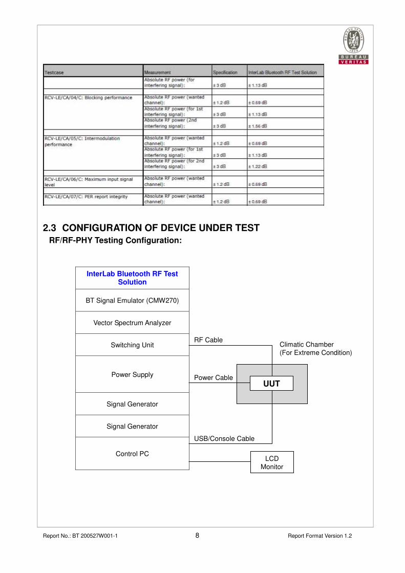
2.2 MEASUREMENT UNCERTAINTY
Uncertainty (factor k=2) was calculated according to the 7Layers InterLab BT RF Test
Suite uncertainty document.

Report No.: BT 200527W001-1 6 Report Format Version 1.2

Report No.: BT 200527W001-1 7 Report Format Version 1.2
Report No.: BT 200527W001-1 8 Report Format Version 1.2
2.3 CONFIGURATION OF DEVICE UNDER TEST
RF/RF-PHY Testing Configuration:
InterLab Bluetooth RF Test Solution
BT Signal Emulator (CMW270)
Vector Spectrum Analyzer
Switching Unit
Power Supply
Signal Generator
Signal Generator
Control PC
Climatic Chamber
(For Extreme Condition)
UUT
LCD
Monitor
Power Cable
RF Cable
USB/Console Cable

Report No.: BT 200527W001-1 9 Report Format Version 1.2
2.4 COMPETENCE AND GUARANTEES
Bureau Veritas is a testing laboratory competent to carry out the tests described in this
report.
In order to assure the traceability to other national and international laboratories,
Bureau Veritas has a calibration and maintenance program for its measurement
equipment.
Bureau Veritas guarantees the reliability of the data presented in this report, which is
the result of the measurements and the tests performed to the item under test on the
date and under the conditions stated on the report and, it is based on the knowledge
and technical facilities available at Bureau Veritas at the time of performance of the
test.
Bureau Veritas is liable to the client for the maintenance of the confidentiality of all
information related to the item under test and the results of the test.

Report No.: BT 200527W001-1 10 Report Format Version 1.2
3 GENERAL CONDITIONS
1. This report is only referred to the item/s that has/have undergone the tests.
2. This report does not constitute or imply on its own an approval of the product by the
Certification Bodies or competent Authorities.
3. This document is only valid if complete; no partial reproduction can be made without
previous written permission of Bureau Veritas.
4. This test report cannot be used partially or in full for publicity and/or promotional
purposes without previous written permission of Bureau Veritas and the Accreditation
Bodies
Report No.: BT 200527W001-1 11 Report Format Version 1.2
4 USAGE OF SAMPLES, TESTING PERIOD AND ENVIRONMENTAL
CONDITIONS
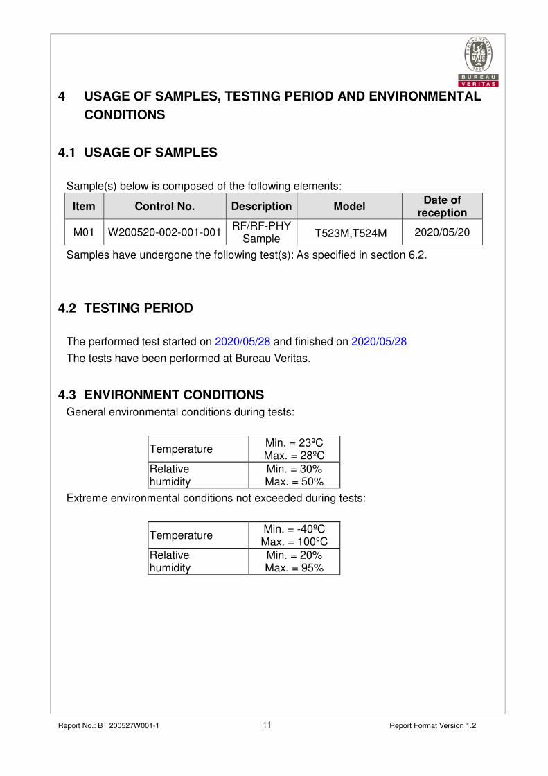
4.1 USAGE OF SAMPLES
Sample(s) below is composed of the following elements:
Item Control No. Description Model Date of
reception
M01 W200520-002-001-001 RF/RF-PHY
Sample T523M,T524M 2020/05/20
Samples have undergone the following test(s): As specified in section 6.2.
4.2 TESTING PERIOD
The performed test started on 2020/05/28 and finished on 2020/05/28
The tests have been performed at Bureau Veritas.
4.3 ENVIRONMENT CONDITIONS
General environmental conditions during tests:
Temperature Min. = 23ºC Max. = 28ºC
Relative humidity
Min. = 30% Max. = 50%
Extreme environmental conditions not exceeded during tests:
Temperature Min. = -40ºC Max. = 100ºC
Relative humidity
Min. = 20% Max. = 95%

Report No.: BT 200527W001-1 12 Report Format Version 1.2
5 DUT CONFORMANCE STATUS
5.1 DYNAMIC CONFORMANCE SUMMARY
The test campaign did NOT reveal any errors on the DUT.
6 TEST RESULTS
6.1 DEFINITION
Abbreviations used in the header row of the test campaign report tables are:
Test Case: This Field contains Test Case ID, Test Case Name, and Test Case
Category. Test Conditions are defined in NOC (Normal Operation
Condition) and EOC (Extreme Operation Condition) for High, Normal and
Low Temperature and Voltage conditions defined by manufacture in IXIT.
Test Case Verdict: Records the verdict of each test case run to completion.
Pass: for test cases whose requirements where fulfilled.
Fail: for test case whose requirements where NOT fulfilled.
NA: for test cases not applicable for testing.
NT: for test cases not tested (e.g. not required by BQC)
Test Execution Date: The execution Date for the test case

Report No.: BT 200527W001-1 13 Report Format Version 1.2
6.2 TEST RESULTS
RF Test Program Version InterLab RF Test Suite v5.2.4
Test Specification RF-PHY.TS.p15
Tested By Alisa Zhao
Test Case ID Condition Date Results Sample ID
TP/RCV-LE/CA/BV-01-C Receiver sensitivity 2020/05/28 Pass M01
TP/RCV-LE/CA/BV-03-C C/I and receiver
selectivity performance 2020/05/28 Pass M01
TP/RCV-LE/CA/BV-04-C Blocking performance 2020/05/28 Pass M01
TP/RCV-LE/CA/BV-05-C Intermodulation
performance 2020/05/28 Pass M01
TP/RCV-LE/CA/BV-06-C Maximum input signal
level 2020/05/28 Pass M01
TP/RCV-LE/CA/BV-07-C PER Report Integrity 2020/05/28 Pass M01
TP/RCV-LE/CA/BV-08-C Receiver sensitivity at
2 Ms/s 2020/05/28 Pass M01
TP/RCV-LE/CA/BV-09-C C/I and Receiver
Selectivity
Performance at 2 Ms/s 2020/05/28 Pass M01
TP/RCV-LE/CA/BV-10-C Blocking performance
at 2 Ms/s 2020/05/28 Pass M01
TP/RCV-LE/CA/BV-11-C Intermodulation
performance at 2 Ms/s 2020/05/28 Pass M01
TP/RCV-LE/CA/BV-12-C Maximum input signal
level at 2 Ms/s 2020/05/28 Pass M01
TP/RCV-LE/CA/BV-13-C PER Report Integrity
at 2 Ms/s 2020/05/28 Pass M01
Report No.: BT 200527W001-1 14 Report Format Version 1.2
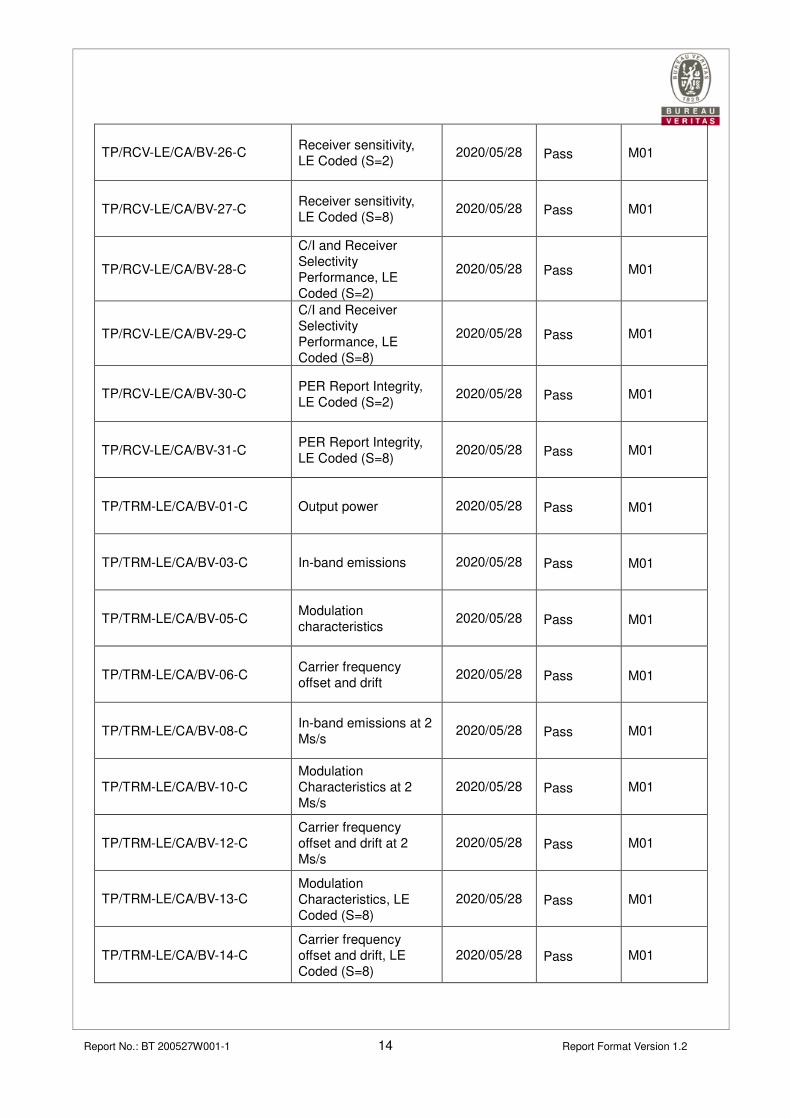
TP/RCV-LE/CA/BV-26-C Receiver sensitivity,
LE Coded (S=2) 2020/05/28 Pass M01
TP/RCV-LE/CA/BV-27-C Receiver sensitivity,
LE Coded (S=8) 2020/05/28 Pass M01
TP/RCV-LE/CA/BV-28-C
C/I and Receiver
Selectivity
Performance, LE
Coded (S=2)
2020/05/28 Pass M01
TP/RCV-LE/CA/BV-29-C
C/I and Receiver
Selectivity
Performance, LE
Coded (S=8)
2020/05/28 Pass M01
TP/RCV-LE/CA/BV-30-C PER Report Integrity,
LE Coded (S=2) 2020/05/28 Pass M01
TP/RCV-LE/CA/BV-31-C PER Report Integrity,
LE Coded (S=8) 2020/05/28 Pass M01
TP/TRM-LE/CA/BV-01-C Output power 2020/05/28 Pass M01
TP/TRM-LE/CA/BV-03-C In-band emissions 2020/05/28 Pass M01
TP/TRM-LE/CA/BV-05-C Modulation
characteristics 2020/05/28 Pass M01
TP/TRM-LE/CA/BV-06-C Carrier frequency
offset and drift 2020/05/28 Pass M01
TP/TRM-LE/CA/BV-08-C In-band emissions at 2
Ms/s 2020/05/28 Pass M01
TP/TRM-LE/CA/BV-10-C Modulation
Characteristics at 2
Ms/s 2020/05/28 Pass M01
TP/TRM-LE/CA/BV-12-C Carrier frequency
offset and drift at 2
Ms/s 2020/05/28 Pass M01
TP/TRM-LE/CA/BV-13-C Modulation
Characteristics, LE
Coded (S=8)
2020/05/28 Pass M01
TP/TRM-LE/CA/BV-14-C
Carrier frequency
offset and drift, LE
Coded (S=8)
2020/05/28 Pass M01

Report No.: BT 200527W001-1 15 Report Format Version 1.2
6.3 REMARKS AND COMMENTS
There are no remarks or comments.

Report No.: BT 200527W001-1 16 Report Format Version 1.2
7 SUMMARY
Considering the results of the performed test, stated in section 6.2, the item/s under
test is/are IN COMPLIANCE with the specifications listed in section 1
“CERTIFICATION INFO”.
NOTE: The results presented in this Test Report apply only to the particular item under
test established in section 4, “USAGE OF SAMPLES, TESTING PERIOD AND
ENVIRONMENTAL CONDITIONS”

Report No.: BT 200527W001-1 17 Report Format Version 1.2
8 INFORMATION ON THE TESTING LABORATORIES
We, BV 7Layers Communications Technology (Shenzhen) Co., Ltd., were founded in
1988 to provide our best service in EMC, GCF/PTCRB, OTA, and BQB. Our
laboratories are accredited and approved according to ISO/IEC 17025.
If you have any comments, please feel free to contact us at the following:
BV 7Layers Communications Technology (Shenzhen) Co., Ltd. Tel: +86 755 8869 6559
Fax: +86 755 8869 6577
Email:[email protected]
Web Site: www.bureauveritas.com
The address and road map of all our labs can be found in our web site also.

Report No.: BT 200527W001-1 18 Report Format Version 1.2
ANNEX A – PICS/PIXIT
IMPLEMENTATION CONFORMANCE STATEMENT (ICS) for RF-PHY
Item Bluetooth LE RF Capability Status Supported
1 LE Transmitter (Non-connectable,
Broadcaster) C.1
�
2 LE Receiver (Non-connectable, Observer) C.1 �
3 LE Transceiver (Connectable,
Peripheral/Central) C.1
�
4 LE 2M PHY C.2 �
5 Stable Modulation Index - Transmitter C.3
6 Stable Modulation Index - Receiver C.4
7 LE Coded PHY C.2 �
C.1: Mandatory to support at least one of these capabilities.
C.2: Optional IF SUM ICS 21/16 “Core 5.0” AND RF PHY 1/3 “LE Transceiver” are supported, otherwise
Excluded.
C.3: Optional IF SUM ICS 21/16 “Core 5.0” AND (RF PHY 1/1 “LE Transmitter” OR RF PHY 1/3 “LE
Transceiver”) are supported, otherwise Excluded.
C.4: Optional IF SUM ICS 21/16 “Core 5.0” AND (RF PHY 1/2 “LE Receiver” OR RF PHY 1/3 “LE
Transceiver”) are supported, otherwise Excluded.
Item Bluetooth LE RF Capability Status Supported
1 HCI Test Interface C.1
2 UART Test Interface C.1 � C.1: Mandatory to support at least one of these capabilities.

Report No.: BT 200527W001-1 19 Report Format Version 1.2
IMPLEMENTATION EXTRA INFORMATION (IXIT) FOR RF-PHY
IXIT
Reference Identifier Sub-Identifier
(Optional) Units
( if applicable ) Value
RF-PHY:P1:1 Inband Image
frequency
Low frequency MHz 4
RF-PHY:P1:2 Middle frequency MHz 4 RF-PHY:P1:3 High frequency MHz 4 RF-PHY:P2:1
Value n for
Intermodulation test
Low frequency Integer 5 RF-PHY:P2:2 Middle frequency Integer 5 RF-PHY:P2:3 High frequency Integer 5 RF-PHY:P3 Type of power source Li+PIN
RF-PHY:P4:1
Power source voltage
Nominal (NOC) V 3.8 RF-PHY:P4:2 Maximum (EOC) V 4.3 RF-PHY:P4:3 Minimum (EOC) V 3.3 RF-PHY:P5:1
Operating temperature
Nominal (NOC) °C 25 RF-PHY:P5:2 Maximum (EOC) °C 85 RF-PHY:P5:3 Minimum (EOC) °C -40 RF-PHY:P6:1
Air humidity range
(relative)
Maximum (EOC) % / RF-PHY:P6:2 Minimum (EOC) % /
RF-PHY:P6:3 Air humidity level for
NOC/EOC tests % 65
RF-PHY:P7:1 Test interface
implementation
HCI or 2-wire UART 2-wire UART
RF-PHY:P7:2 Datarate bps 19200 RF-PHY-PHY:P8 Antenna gain dBi 0
RF-PHY:P9:1 Maximum TX
packet length 37~255(Bytes) 255
RF-PHY:P9:2 Maximum RX
packet length 37~255(Bytes) 255
RF-PHY:P9:3 Maximum TX
packet length 2M 37~255(Bytes) 255
RF-PHY:P9:4 Maximum TX
packet length S=2 37~255(Bytes) 255
RF-PHY:P9:5 Maximum TX
packet length S=8 37~255(Bytes) 255
RF-PHY:P9:6 Maximum RX
packet length 2M 37~255(Bytes) 255
RF-PHY:P9:7 Maximum RX
packet length S=2 37~255(Bytes) 255
RF-PHY:P9:8 Maximum RX
packet length S=8 37~255(Bytes) 255
RF-PHY:P10:1 Maximum TX
mode output power
-20(dBm) to 10
(dbm) (CSA5
unsupported) /
RF-PHY:11:1 Inband Image
Frequency (2Ms/s)
Low frequency MHz 8
RF-PHY:11:2 Middle frequency MHz 8 RF-PHY:11:3 High frequency MHz 8

Report No.: BT 200527W001-1 20 Report Format Version 1.2
RF-PHY:12:1 Value n for
Intermodulation
test (2Ms/s)length
Low frequency Integer 5
RF-PHY:12:2 Middle frequency Integer 5
RF-PHY:12:3 High frequency Integer 5
RF-PHY:13:1 Inband Image
Frequency
(Stable Modulation
Receiver)
Low frequency MHz /
RF-PHY:13:2 Middle frequency MHz /
RF-PHY:13:3 High frequency MHz /
RF-PHY:14:1 Value n for
Intermodulation
test
(Stable Modulation
Receiver)
Low frequency Integer /
RF-PHY:14:2 Middle frequency Integer /
RF-PHY:14:3 High frequency Integer /
RF-PHY:15:1 Inband Image
Frequency
(Stable Modulation
Receiver, 2Ms/s)
Low frequency MHz 8
RF-PHY:15:2 Middle frequency MHz 8
RF-PHY:15:3 High frequency MHz 8
RF-PHY:16:1 Value n for
Intermodulation
test
(Stable Modulation
Receiver, 2Ms/s)
Low frequency Integer 5
RF-PHY:16:2 Middle frequency Integer 5
RF-PHY:16:3 High frequency Integer
5

Report No.: BT 200527W001-1 21 Report Format Version 1.2
ANNEX B – PHOTOGRAPHS
---END---