bluemod+sr hardware user guide - telit · bluemod+sr hardware user guide 1vv0301276 rev. 14 page 3...
TRANSCRIPT
[01.2
017]
Mod. 0805 2017-01 Rev.6
BlueMod+SR Hardware User Guide
1VV0301276 Rev. 14 – 2017-06-07
BlueMod+SR Hardware User Guide
1VV0301276 Rev. 14 Page 2 of 84 2017-06-07
SPECIFICATIONS ARE SUBJECT TO CHANGE WITHOUT NOTICE
NOTICE
While reasonable efforts have been made to assure the accuracy of this document, Telit assumes no liability resulting from any inaccuracies or omissions in this document, or from use of the information obtained herein. The information in this document has been carefully checked and is believed to be reliable. However, no responsibility is assumed for inaccuracies or omissions. Telit reserves the right to make changes to any products described herein and reserves the right to revise this document and to make changes from time to time in content hereof with no obligation to notify any person of revisions or changes. Telit does not assume any liability arising out of the application or use of any product, software, or circuit described herein; neither does it convey license under its patent rights or the rights of others.
It is possible that this publication may contain references to, or information about Telit products (machines and programs), programming, or services that are not announced in your country. Such references or information must not be construed to mean that Telit intends to announce such Telit products, programming, or services in your country.
COPYRIGHTS
This instruction manual and the Telit products described in this instruction manual may be, include or describe copyrighted Telit material, such as computer programs stored in semiconductor memories or other media. Laws in the Italy and other countries preserve for Telit and its licensors certain exclusive rights for copyrighted material, including the exclusive right to copy, reproduce in any form, distribute and make derivative works of the copyrighted material. Accordingly, any copyrighted material of Telit and its licensors contained herein or in the Telit products described in this instruction manual may not be copied, reproduced, distributed, merged or modified in any manner without the express written permission of Telit. Furthermore, the purchase of Telit products shall not be deemed to grant either directly or by implication, estoppel, or otherwise, any license under the copyrights, patents or patent applications of Telit, as arises by operation of law in the sale of a product.
COMPUTER SOFTWARE COPYRIGHTS
The Telit and 3rd Party supplied Software (SW) products described in this instruction manual may include copyrighted Telit and other 3rd Party supplied computer programs stored in semiconductor memories or other media. Laws in the Italy and other countries preserve for Telit and other 3rd Party supplied SW certain exclusive rights for copyrighted computer programs, including the exclusive right to copy or reproduce in any form the copyrighted computer program. Accordingly, any copyrighted Telit or other 3rd Party supplied SW computer programs contained in the Telit products described in this instruction manual may not be copied (reverse engineered) or reproduced in any manner without the express written permission of Telit or the 3rd Party SW supplier. Furthermore, the purchase of Telit products shall not be deemed to grant either directly or by implication, estoppel, or otherwise, any license under the copyrights, patents or patent applications of Telit or other 3rd Party supplied SW, except for the normal non-exclusive, royalty free license to use that arises by operation of law in the sale of a product.

BlueMod+SR Hardware User Guide
1VV0301276 Rev. 14 Page 3 of 84 2017-06-07
USAGE AND DISCLOSURE RESTRICTIONS
I. License Agreements
The software described in this document is the property of Telit and its licensors. It is furnished by express license agreement only and may be used only in accordance with the terms of such an agreement.
II. Copyrighted Materials
Software and documentation are copyrighted materials. Making unauthorized copies is prohibited by law. No part of the software or documentation may be reproduced, transmitted, transcribed, stored in a retrieval system, or translated into any language or computer language, in any form or by any means, without prior written permission of Telit
III. High Risk Materials
Components, units, or third-party products used in the product described herein are NOT fault-tolerant and are NOT designed, manufactured, or intended for use as on-line control equipment in the following hazardous environments requiring fail-safe controls: the operation of Nuclear Facilities, Aircraft Navigation or Aircraft Communication Systems, Air Traffic Control, Life Support, or Weapons Systems (High Risk Activities"). Telit and its supplier(s) specifically disclaim any expressed or implied warranty of fitness for such High Risk Activities.
IV. Trademarks
TELIT and the Stylized T Logo are registered in Trademark Office. All other product or service names are the property of their respective owners.
V. Third Party Rights
The software may include Third Party Right software. In this case you agree to comply with all terms and conditions imposed on you in respect of such separate software. In addition to Third Party Terms, the disclaimer of warranty and limitation of liability provisions in this License shall apply to the Third Party Right software.
TELIT HEREBY DISCLAIMS ANY AND ALL WARRANTIES EXPRESS OR IMPLIED FROM ANY THIRD PARTIES REGARDING ANY SEPARATE FILES, ANY THIRD PARTY MATERIALS INCLUDED IN THE SOFTWARE, ANY THIRD PARTY MATERIALS FROM WHICH THE SOFTWARE IS DERIVED (COLLECTIVELY “OTHER CODE”), AND THE USE OF ANY OR ALL THE OTHER CODE IN CONNECTION WITH THE SOFTWARE, INCLUDING (WITHOUT LIMITATION) ANY WARRANTIES OF SATISFACTORY QUALITY OR FITNESS FOR A PARTICULAR PURPOSE.
NO THIRD PARTY LICENSORS OF OTHER CODE SHALL HAVE ANY LIABILITY FOR ANY DIRECT, INDIRECT, INCIDENTAL, SPECIAL, EXEMPLARY, OR CONSEQUENTIAL DAMAGES (INCLUDING WITHOUT LIMITATION LOST PROFITS), HOWEVER CAUSED AND WHETHER MADE UNDER CONTRACT, TORT OR OTHER LEGAL THEORY, ARISING IN ANY WAY OUT OF THE USE OR DISTRIBUTION OF THE OTHER CODE OR THE EXERCISE OF ANY RIGHTS GRANTED UNDER EITHER OR BOTH THIS LICENSE AND THE LEGAL TERMS APPLICABLE TO ANY SEPARATE FILES, EVEN IF ADVISED OF THE POSSIBILITY OF SUCH DAMAGES.

BlueMod+SR Hardware User Guide
1VV0301276 Rev. 14 Page 4 of 84 2017-06-07
APPLICABILITY TABLE
PRODUCTS
BLUEMOD+SR/AI
BLUEMOD+SR/AP

BlueMod+SR Hardware User Guide
1VV0301276 Rev. 14 Page 5 of 84 2017-06-07
Contents
NOTICE ..................................................................................................... 2
COPYRIGHTS ................................................................................................ 2
COMPUTER SOFTWARE COPYRIGHTS ...................................................... 2
USAGE AND DISCLOSURE RESTRICTIONS ............................................... 3
I. License Agreements ..................................................................... 3
II. Copyrighted Materials ................................................................... 3
III. High Risk Materials ....................................................................... 3
IV. Trademarks .................................................................................. 3
V. Third Party Rights ......................................................................... 3
APPLICABILITY TABLE ................................................................................ 4
CONTENTS .................................................................................................... 5
1. INTRODUCTION .......................................................................... 9
Scope ........................................................................................... 9
Audience....................................................................................... 9
Contact Information, Support ........................................................ 9
Text Conventions ........................................................................ 10
Related Documents .................................................................... 11
2. OVERVIEW ................................................................................ 12
Feature Summary ....................................................................... 13
Applications ................................................................................ 13
2.2.1. General Cable Replacement ....................................................... 14
2.2.2. Industry ....................................................................................... 14
2.2.3. Automotive .................................................................................. 14
2.2.4. Healthcare and Medical .............................................................. 14
2.2.5. Sports and Fitness ...................................................................... 14
2.2.6. Entertainment ............................................................................. 14
3. BLOCK DIAGRAM ..................................................................... 15
4. APPLICATION INTERFACE ...................................................... 16
Power Supply ............................................................................. 16
Power-up/down Slew Rate .......................................................... 16
Reset .......................................................................................... 17

BlueMod+SR Hardware User Guide
1VV0301276 Rev. 14 Page 6 of 84 2017-06-07
Supply Voltage Monitor ............................................................... 18
Serial Interface ........................................................................... 19
4.5.1. 3-Wire Serial Interface ................................................................ 20
4.5.2. UART Example Circuits .............................................................. 20
4.5.3. Baud Rate Deviation ................................................................... 22
GPIO Interface ............................................................................ 23
I2C Interface ............................................................................... 24
NFC Support .............................................................................. 25
SPI Serial Peripheral Interface ................................................... 26
Bluetooth Radio Interface ........................................................... 26
WLAN Coexistence Interface ...................................................... 27
Slow Clock Interface ................................................................... 27
Test Mode ................................................................................... 28
Pin Strapped System Memory Boot Mode Invocation ................. 28
Operating in a Power Switched Environment .............................. 28
Serial Wire Debug Interface ........................................................ 29
Trace Interface ........................................................................... 29
5. MODULE PINS ........................................................................... 30
Pin Numbering ............................................................................ 30
General Pin Description .............................................................. 31
Application Specific SPP Pin Configuration ................................. 33
Handling of Unused Signals ........................................................ 34
6. ELECTRICAL CHARACTERISTICS .......................................... 35
Absolute Maximum Ratings ........................................................ 35
Electrical Requirements .............................................................. 35
Operating Conditions .................................................................. 35
Environmental Requirements ...................................................... 35
Digital I/O Including EXT-RES# .................................................. 36
Power Consumption and Power Down Modes ............................ 39
6.6.1. Classic Bluetooth ........................................................................ 39
6.6.2. LE Configurations ....................................................................... 40
6.6.2.1. LE Operating in Peripheral Device Role ...................................... 40
6.6.2.2. LE Operating in Central Device Role .......................................... 41
RF Performance ......................................................................... 42
6.7.1. GFSK, PI/4 DQPSK, 8DPSK Receiver ........................................ 42
6.7.2. GFSK, PI/4 DQPSK, 8DPSK Transmitter .................................... 45
6.7.3. BLE Receiver .............................................................................. 48

BlueMod+SR Hardware User Guide
1VV0301276 Rev. 14 Page 7 of 84 2017-06-07
6.7.4. BLE Transmitter .......................................................................... 50
6.7.5. Antenna Gain and Radiation Pattern ........................................... 52
Power-Up Time ........................................................................... 54
7. MECHANICAL CHARACTERISTICS ......................................... 55
Dimensions ................................................................................. 55
Recommended Land Pattern ...................................................... 56
Re-flow Temperature Time Profile .............................................. 57
Placement Recommendation ...................................................... 58
Housing Guidelines ..................................................................... 58
Antenna Issues ........................................................................... 59
Safety Guidelines ........................................................................ 59
Cleaning ..................................................................................... 59
8. APPLICATION DIAGRAM.......................................................... 60
9. APPROVALS/CERTIFICATIONS ............................................... 61
Declaration of Conformity CE ...................................................... 61
FCC Compliance ........................................................................ 61
9.2.1. FCC Grant .................................................................................. 62
9.2.2. FCC Statement ........................................................................... 64
9.2.3. FCC Caution ............................................................................... 64
9.2.4. FCC Warning .............................................................................. 64
9.2.5. FCC RF-exposure Statement ...................................................... 64
9.2.6. FCC Labeling Requirements for the End Product ....................... 65
IC Compliance ............................................................................ 65
9.3.1. IC Grant ...................................................................................... 66
9.3.2. IC Statement ............................................................................... 67
9.3.3. IC Caution ................................................................................... 67
9.3.4. IC RF-exposure Statement ......................................................... 67
9.3.5. IC Labeling Requirements for the End Product ........................... 68
9.3.6. IC Label Information BlueMod+SR .............................................. 68
KC Certification ........................................................................... 69
9.4.1. KC Certificate ............................................................................. 69
MIC Certification ......................................................................... 70
9.5.1. MIC Certificates .......................................................................... 71
Anatel Certification ...................................................................... 73
Bluetooth Qualification ................................................................ 74
RoHS Declaration ....................................................................... 75

BlueMod+SR Hardware User Guide
1VV0301276 Rev. 14 Page 8 of 84 2017-06-07
10. PACKING ................................................................................... 76
Tape&Reel Packing .................................................................... 76
10.1.1. Tape ........................................................................................... 77
10.1.2. Reel ............................................................................................ 77
Tray Packing ............................................................................... 78
10.2.1. Module Orientation ..................................................................... 78
10.2.2. Tray Dimension........................................................................... 78
Moisture Sensitivity Level ........................................................... 78
11. EVALUATION KIT ...................................................................... 79
12. SAFETY RECOMMENDATIONS................................................ 80
READ CAREFULLY .................................................................... 80
13. DOCUMENT HISTORY .............................................................. 81

BlueMod+SR Hardware User Guide
1VV0301276 Rev. 14 Page 9 of 84 2017-06-07
1. INTRODUCTION
Scope
This document provides information how the BlueMod+SR can be integrated into customer systems. It addresses hardware specifications of the BlueMod+SR and requirements of the hardware environments for the BlueMod+SR.
Audience
This document is intended for Telit customers, especially system integrators, about to implement Bluetooth modules in their application.
Contact Information, Support
For general contact, technical support services, technical questions and report documentation errors contact Telit Technical Support at:
[email protected] for global Bluetooth support
Alternatively, use:
http://www.telit.com/support
For detailed information about where you can buy the Telit modules or for recommendations on accessories and components visit:
http://www.telit.com
Our aim is to make this guide as helpful as possible. Keep us informed of your comments and suggestions for improvements.
Telit appreciates feedback from the users of our information.

BlueMod+SR Hardware User Guide
1VV0301276 Rev. 14 Page 10 of 84 2017-06-07
Text Conventions
Danger – This information MUST be followed or catastrophic equipment failure or bodily injury may occur.
Caution or Warning – Alerts the user to important points about integrating the module, if these points are not followed, the module and end user equipment may fail or malfunction.
Tip or Information – Provides advice and suggestions that may be useful when integrating the module.
All dates are in ISO 8601 format, i.e. YYYY-MM-DD.
BlueMod+SR Hardware User Guide
1VV0301276 Rev. 14 Page 11 of 84 2017-06-07
Related Documents
[1] CD00171190.pdf Oct. 2011 Rev 14 (STM32_Reference)
[2] CD00191185.pdf April 2011 Rev 8 (STM32_datasheet)
[3] UICP+ UART Interface Control Protocol, 30507ST10756A
[4] BlueMod+SR AT Command Reference, 80507ST10752A
[5] BlueMod+SR Software User Guide, 1VV0301278
BlueMod+SR Hardware User Guide
1VV0301276 Rev. 14 Page 12 of 84 2017-06-07
2. OVERVIEW
This document provides information how the BlueMod+SR/AI and BlueMod+SR/AP can be
integrated into customer systems. It addresses hardware specifications of the
BlueMod+SR/AI and /AP and requirements of the hardware environments for the
BlueMod+SR/AI and BlueMod+SR/AP.
The term BlueMod+SR refers to the BlueMod+SR/AI and the BlueMod+SR/AP.
For detailed information about software interfaces refer to [4].
For the latest version of this document please check the following URL:
http://www.telit.com/bluetooth/bluemod-sr/
The integration of the BlueMod+SR module within user application shall be done according to the design rules described in this manual.
The information presented in this document is believed to be accurate and reliable.
However, no responsibility is assumed by Telit Communications S.p.A. for its use, nor any
infringement of patents or other rights of third parties which may result from its use. No
license is granted by implication or otherwise under any patent rights of Telit
Communications S.p.A. other than for circuitry embodied in Telit products. This document
is subject to change without notice.

BlueMod+SR Hardware User Guide
1VV0301276 Rev. 14 Page 13 of 84 2017-06-07
Feature Summary
Bluetooth specification V4.0 compliant
Supports BR/EDR/LE
Supports Dual Mode
Fully qualified Bluetooth V4.0 Dual Mode BR/EDR/LE
CE certified
FCC, IC and KCC certified
CSR8811 BlueCore08 and Application Processor inside
Complete Co-location and Co-existence with 802.11 (AFH, Unity 3e+)
Fast Connection Setup
RF output power up to +7dBm with power control
Supply Voltage range 2,5V to 3,6V, typical 3.3V
Internal crystal oscillator (26 MHz and 14,7456 MHz)
LGA Surface mount type: BlueMod+SR: 17 x 10 x 2.6 mm3
Shielded to be compliant to FCC full modular approval
Bluetooth enhanced data rate up to 2178kbps asymmetric
Support for all Bluetooth power saving modes (Park, Sniff, Hold)
Optional support for ultra-low-power mode
Full 8- to 128-bit encryption
High sensitivity design
High-speed UART interface
I2C interface
SPI interface
Up to 11 digital IO’s for individual usage by embedded software
Cortex-M3 STM32F103 core for embedded profiles or application software
Manufactured in conformance with RoHS2
Operating temperature -30 ... +85 °C
Weight: 0,8 g
Applications
The BlueMod+SR can be used in different applications. Regardless if the application
requires high throughput or low energy consumption, BlueMod+SR offers the best of both
worlds. Some typical applications are described in this chapter.
Supported profiles are:
BR/EDR:
SPP
LE:
Terminal I/O
GATT based LE profiles
Support for any additional profile is possible on request.

BlueMod+SR Hardware User Guide
1VV0301276 Rev. 14 Page 14 of 84 2017-06-07
2.2.1. General Cable Replacement
The Serial Port Profile (SPP) on the BlueMod+SR can be used for UART data transfer. The
connection is transparent for the user application and supports Secure Simple Pairing,
making the pairing process easy and the connection secure.
2.2.2. Industry
Typical Bluetooth application include scanner, printer as well as automation controls. In the
automation application area Bluetooth is mainly used for transport of I/O signals. Bluetooth
low energy can be used to monitor and control motors, actuators, values and entire
processes.
2.2.3. Automotive
Modules are mainly used in aftermarket application like personal navigation devices, head
units or audio applications. These applications are typically Bluetooth BR/EDR only.
2.2.4. Healthcare and Medical
The healthcare and medical market offers a lot of possible application for Bluetooth BR/EDR
and Bluetooth Low Energy. Usage of Bluetooth is aimed mainly at devices that are used for
monitoring vital data. Typical devices are blood glucose meter, blood pressure cuffs and
pulse ox meters. Bluetooth BR/EDR and low energy were chosen by the Continua Health
Alliance as transports for interoperable end to end communication.
2.2.5. Sports and Fitness
In the sports and fitness segment Bluetooth is used in devices for positioning as well as
monitoring vital data. Typical devices in this market are heart rate monitors, body
temperature thermometers, pedometers, cadence meters, altimeter, positioning / GPS
tracking and watches displaying information from sensors.
2.2.6. Entertainment
Bluetooth technology is already used in a wide variety of devices in the entertainment
sector, namely set-top boxes / gaming consoles. Bluetooth low energy is expected to further
increase the use of Bluetooth technology in devices like TV / DVD / STB / Media Player,
remote controls, gaming controller, wireless mouse/keyboard.

BlueMod+SR Hardware User Guide
1VV0301276 Rev. 14 Page 15 of 84 2017-06-07
3. BLOCK DIAGRAM
STM32F103
VSUP
BlueMod+SR
BPFilter
RE
SE
T
I2C
UA
RT
SP
I
1273
GND
3.0V
26MHz
opt. 3
2kH
z
Serial Wire(DEBUG)
onboardantenna
GP
IO9
TRACE
EEPROM14,7456MHz
CSR8811
WLA
N-C
OE
X4
EX
T-A
NT
1)
1)
2)
2)
BlueMod+SR/AI only
BlueMod+SR/AP only
Figure 1: BlueMod+SR Block Diagram
BlueMod+SR/AI has an internal ceramic antenna whereas BlueMod+SR/AP provides for an 50Ω RF interface.

BlueMod+SR Hardware User Guide
1VV0301276 Rev. 14 Page 16 of 84 2017-06-07
4. APPLICATION INTERFACE
Power Supply
BlueMod+SR require a power supply with the following characteristics:
Typical: 3,3VDC, min.: 2,5VDC, max.: 3,6VDC, > 80mA peak
For optimal performance a stable supply is recommended. If a regulator is to be used, it
should be a fast linear regulator placed as close as possible to the VSUP pins (E-6, F-6).
Functionality has been verified with the following type: TOREX: XC6204x332xx.
If the regulator cannot be placed close to the BlueMod+SR, it is recommended to place an
additional low ESR capacitor with at least 1µF as close as possible to the VSUP pins (E-6,
F-6 or C-1).
BlueMod+SR
XC6204-3.3C-1,E-6,F-6
VSUP
GND:A-7,E-7,F-7,B-[5:8],C-[5:8],D-8,E-8,F-8
10µ + 100n + 1n
1µ
VOUT
VSS
VIN
CE
5 1
3
2
+5VDC
Figure 2: BlueMod+SR example power supply
Power-up/down Slew Rate
Table 1: Power up/down slew rate requirements
Parameter Min Max Unit
VSUP rise time rate 1 ∞ µs/V
VSUP fall time rate 20 ∞
The VSUP voltage has to rise continuously from 0V to the minimum VSUP operating voltage
defined in Table 8: DC operating conditions.
BlueMod+SR Hardware User Guide
1VV0301276 Rev. 14 Page 17 of 84 2017-06-07
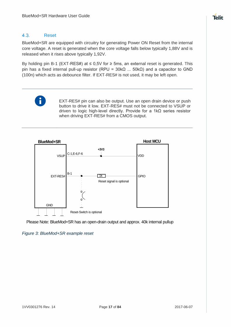
Reset
BlueMod+SR are equipped with circuitry for generating Power ON Reset from the internal
core voltage. A reset is generated when the core voltage falls below typically 1,88V and is
released when it rises above typically 1,92V.
By holding pin B-1 (EXT-RES#) at ≤ 0,5V for ≥ 5ms, an external reset is generated. This
pin has a fixed internal pull-up resistor (RPU = 30kΩ ... 50kΩ) and a capacitor to GND
(100n) which acts as debounce filter. If EXT-RES# is not used, it may be left open.
EXT-RES# pin can also be output. Use an open drain device or push button to drive it low. EXT-RES# must not be connected to VSUP or driven to logic high-level directly. Provide for a 1kΩ series resistor when driving EXT-RES# from a CMOS output.
BlueMod+SR
C-1,E-6,F-6VSUP
GND
+3V3
EXT-RES#B-1
Reset-Switch is optional
Please Note: BlueMod+SR has an open-drain output and approx. 40k internal pullup
1k
Reset signal is optional
Host MCU
GPIO
VDD
Figure 3: BlueMod+SR example reset

BlueMod+SR Hardware User Guide
1VV0301276 Rev. 14 Page 18 of 84 2017-06-07
The following table shows the pin states of BlueMod+SR during reset active.
Table 2: Pin states during reset
Pin Name State BlueMod+SR
EXT-RES# I/O with pull-up (1) and 100n to GND – use open drain
SLCK Input with weak pull-down (2)
UART-TXD Input floating
UART-RXD Input floating
UART-RTS# Input with pull-up resistor 470kΩ (4)
UART-CTS# Input floating
IUR-OUT# Input with pull-up resistor 470kΩ (4)
IUR-IN# Input floating
GPIO[0:4, 6:7] Input floating
GPIO[5] Input with pull-up (1)
GPIO[8] Output (JTDO)
BT-ACT Input with weak pull-up (2)
BT-STAT Input with weak pull-up (2)
WLAN-DNY Input with weak pull-up (2)
BT-PER Input with weak pull-up (2)
TESTMODE# Input floating
BOOT0 Input with pull-down resistor 100kΩ (4)
SWDIO Input with pull-up (1)
SWCLK Input with pull-down (1)
(1) pull-up, pull-down: RPU, RPD is typ. 40kΩ (30kΩ to 50kΩ) (2) weak pull-up, pull-down: See Table 12: DC characteristics, digital IO (CSR8811 related) (3) strong pull-up, pull-down: See Table 12: DC characteristics, digital IO (CSR8811 related) (4) a discrete resistor is used
The pin states as indicated in Table 2 are kept until hardware initialization has started.
Supply Voltage Monitor
Supply-under-voltage detection is implemented using the STM32 embedded supply voltage
monitor PVD. When VSUP falls below a threshold VPVD (programmed to 2,38V ± 0,1V), a
system reset will be asserted.

BlueMod+SR Hardware User Guide
1VV0301276 Rev. 14 Page 19 of 84 2017-06-07
Serial Interface
The serial interface of BlueMod+SR is a high-speed UART interface supporting RTS/CTS
flow control and interface-up/down mechanism according to the UICP+ protocol (refer to
[3]). Electrical interfacing is at CMOS levels (defined by VSUP).
Transmission speeds are 9600 – 921600 bps (asynchronous)
Character representation: 8 Bit, no parity, 1 stop bit (8N1)
Hardware flow-control with RTS and CTS (active low)
Transmission speed may be limited by firmware. See corresponding command reference [4] for further information.
BlueMod+SR
Host
UART-RXD
UART-TXD
UART-CTS#
UART-RTS#
IUR-IN#
IUR-OUT#
GND
Figure 4: Serial interface signals
The basic serial interface (with RTS/CTS flow control) uses only four signal lines (UART-
RXD, UART-TXD, UART-CTS#, UART-RTS#). IUR-IN#, IUR-OUT# and GPIO[4] (see
below) can be left unconnected.
A substantially saving of power during idle phases can be achieved (see 6.6.1) when the
UICP protocol is used (refer to [3] ). This protocol should be implemented on the host side
as well. Signals IUR-IN# and IUR-OUT# should be connected to the host and may be
mapped to DSR and DTR, if an RS232-style (DTE-type) interface is used (see Figure 5).
When using the SPP firmware and applications, call control can be supported by GPIO[4].
Driving GPIO[4] to logic High level during a data transfer phase will “hang up” the connection
and disconnect the Bluetooth link. This signal may be mapped to DSR, if an RS232-style
(DTE-type) interface is used. Please refer to [4] for a functional specification. GPIO[4] can
be left unconnected if this feature is not used.

BlueMod+SR Hardware User Guide
1VV0301276 Rev. 14 Page 20 of 84 2017-06-07
4.5.1. 3-Wire Serial Interface
When using only GND and UART-RXD, UART-TXD serial lines, leave UART-RTS# and
UART-CTS# open.
It is strongly recommended to use hardware flow control. Not using flow control can cause a loss of data. When RTS/CTS is not used (3-wire interface) the DTE may sent a limited number of Bytes (depending on buffer size) to the UART interface of the BlueMod+SR without losing data (e.g. 1 kByte by using firmware version 1.310).
4.5.2. UART Example Circuits
2
BlueMod+SR
GND
MAX3241
14
+3V322
23
2
3
7
8
4
6
1
9
TXD
RXD
RTS#
CTS#
IUR-OUT#
IUR-IN#
TXD
RXD
RTS
CTS
DTR
DSR
DCD
RI
RS232
DSUB9 (male)DTE style connector
9
4
10
5
11
6
7
8
19
13
18
12
17
16
15
F-4
D-2
D-7
F-3
B-4
D-5
UART_TXD
UART_RXD
UART_RTS#
UART_CTS#
IUR-OUT#
IUR-IN#
SHDN#
EN#
100n
100n
28
24
1
+3V3
100n 100n 100n
26
327
25
V+
VCC
V -
GND
C2+
C2-
C1+
C1-
220R
220R
220R
220R
220R
220R
5SigGND
can be left open
VSUP +3V3
Figure 5: BlueMod+SR example serial interface (RS-232) supporting UICP

BlueMod+SR Hardware User Guide
1VV0301276 Rev. 14 Page 21 of 84 2017-06-07
VDDIO(+1.2V .. +3.6V)
BlueMod+SR
GND
D-2
F-4
F-3
D-7
UART_RXD
UART_TXD
UART_CTS#
UART_RTS#
10µ+100n+1n
SN74AVC4T245
User Host System
VSUP
XC6204-3.3
VOUT
VSS
VIN
CE
1µ
100k
100k
VCCB
1B1
1B2
2B1
2B2 2A2
2A1
1A2
1A1
VCCA
1DIR
1OE
2DIR
2OE
(GPIO, Out, no pu/pd)
(GPIO, Out, no pu/pd)
TXD
RTS#
RXD
CTS#
+5VDC
OE_DRV#
BT_ENABLE
VDD_HOST (+1.2 .. +3.6V)
+3V3_switched
Figure 6: BlueMod+SR example serial interface (mixed signal level)
BlueMod+SR Hardware User Guide
1VV0301276 Rev. 14 Page 22 of 84 2017-06-07
4.5.3. Baud Rate Deviation
The information on how to set standard or custom baud rates can be found in [4]
BlueMod+SR AT Command Reference.
Assumed that on both sides the TX and RX baud rates are nominally equal, the total baud
rate deviation is the sum of the host baud rate deviation and the BlueMod+SR baud rate
deviation. The total baud rate deviation shall not exceed 2.5% to prevent loss of data. Some
margin should be considered to cover deviations through the transmission line, e.g. due to
asymmetry in low to high and high to low transitions.
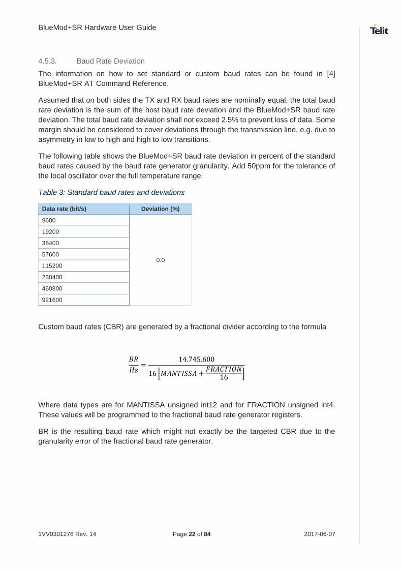
The following table shows the BlueMod+SR baud rate deviation in percent of the standard
baud rates caused by the baud rate generator granularity. Add 50ppm for the tolerance of
the local oscillator over the full temperature range.
Table 3: Standard baud rates and deviations
Data rate (bit/s) Deviation (%)
9600
0.0
19200
38400
57600
115200
230400
460800
921600
Custom baud rates (CBR) are generated by a fractional divider according to the formula
𝐵𝑅
𝐻𝑧=
14.745.600
16 [𝑀𝐴𝑁𝑇𝐼𝑆𝑆𝐴 +𝐹𝑅𝐴𝐶𝑇𝐼𝑂𝑁
16 ]
Where data types are for MANTISSA unsigned int12 and for FRACTION unsigned int4.
These values will be programmed to the fractional baud rate generator registers.
BR is the resulting baud rate which might not exactly be the targeted CBR due to the
granularity error of the fractional baud rate generator.

BlueMod+SR Hardware User Guide
1VV0301276 Rev. 14 Page 23 of 84 2017-06-07
Therefore the baud rate deviation can be calculated by the following procedure:
𝐷𝐼𝑉 =14.745.600
16 𝐶𝐵𝑅
𝑀𝐴𝑁𝑇𝐼𝑆𝑆𝐴 = 𝑚𝑎𝑡ℎ. 𝑓𝑙𝑜𝑜𝑟 (𝐷𝐼𝑉)
𝐹𝑅𝐴𝐶𝑇𝐼𝑂𝑁 = 𝑚𝑎𝑡ℎ. 𝑟𝑜𝑢𝑛𝑑 [16(𝐷𝐼𝑉 − 𝑀𝐴𝑁𝑇𝐼𝑆𝑆𝐴)
If FRACTION > 15
MANTISSA := MANTISSA + 1
FRACTION := 0
𝐵𝑅
𝐻𝑧=
14.745.600
16 [𝑀𝐴𝑁𝑇𝐼𝑆𝑆𝐴 +𝐹𝑅𝐴𝐶𝑇𝐼𝑂𝑁
16 ]
𝐷𝑒𝑣𝑖𝑎𝑡𝑖𝑜𝑛
%= 100 𝑚𝑎𝑡ℎ. 𝑎𝑏𝑠 [
𝐶𝐵𝑅 − 𝐵𝑅
𝐶𝐵𝑅]
Explanation of used functions and expressions:
math.floor(x) returns the largest integer less than or equal to x
math.round(x) returns a number of x rounded to the nearest integer
math.abs(x) returns the absolute value of x
DIV floating variable
CBR targeted customer baud rate
BR actual resulting baud rate
MANTISSA unsigned int12 baud rate register value
FRACTION unsigned int4 baud rate register value
GPIO Interface
It is possible to use the programmable digital I/Os GPIO[0:8] on the BlueMod+SR. Their
behavior has to be defined project specific in the firmware.
Unused GPIO pins can be left unconnected.

BlueMod+SR Hardware User Guide
1VV0301276 Rev. 14 Page 24 of 84 2017-06-07
I2C Interface 1
The I2C bus interface serves as an interface between the internal microcontroller and the
serial I2C bus. It provides multimaster capability, and controls all I2C bus specific
sequencing, protocol, arbitration and timing. It supports standard (100kHz) and fast
(400kHz) speed modes.
GPIO[1]/I2C-SDA and GPIO[0]/I2C-SCL can be used to form an I2C interface. It is required
to connect 4k7 pull-up resistors on I2C-SCL and I2C-SDA when this interface is used.
I2C-SCL
I2C-SDA
GPIO[0]/I2C-SCL
GPIO[1]/I2C-SDA
BlueMod+SR
VSUP
Rpu4k7
+3.3V
B-2
D-3
C-1,E-6,F-6
+3.3V
Rpu4k7
+3.3V
NXP: NT3H1101
Figure 7: BlueMod+SR I2C interface
1 subject to firmware support, contact Telit for current status

BlueMod+SR Hardware User Guide
1VV0301276 Rev. 14 Page 25 of 84 2017-06-07
NFC Support 2
From SPP firmware version V1.500 on and higher the NFC TAG NXP: NT3H1101 will be
supported by using the following signals:
BlueMod+SR Pin Number
BlueMod+SR Signal Name
NFC Function Signal Name
Type Function
D-3 GPIO[0] NFC_SCLK O-OD NFC TAG NXP: NT3H1101 I2C SCLK
B-2 GPIO[1] NFC_SDA I/O NFC TAG NXP: NT3H1101 I2C SDA
C-3 GPIO[7] NFC_FD I-PU NFC TAG NXP: NT3H1101 Field Detect
GPIO[1]/NFC-SDA and GPIO[0]/NFC-SCL are used to form the I2C interface. It is required
to connect 4k7 pull-up resistors on NFC-SCL and NFC-SDA when this interface is used.
I2C-SCL
I2C-SDA
GPIO[0]/I2C-SCL
GPIO[1]/I2C-SDA
BlueMod+SR
VSUP
Rpu4k7
+3.3V
B-2
D-3
C-1,E-6,F-6
+3.3V
Rpu4k7
+3.3V
NXP: NT3H1101
3
5
VCC6
FD (OD)GPIO[7]/FDPU in CPU
4C-3
Figure 8: Connection to the NFC tag NXP: NT3H1101
The NFC TAG NXP: NT3H1101 works over the full voltage and temperature range of the
BlueMod+SR.
2 SPP FW version V1.500 and higher will use this interface to support NFC TAG NXP: NT3H1101 I2C interface
BlueMod+SR Hardware User Guide
1VV0301276 Rev. 14 Page 26 of 84 2017-06-07
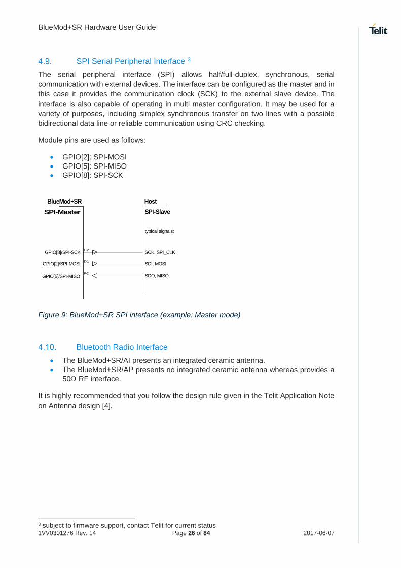
SPI Serial Peripheral Interface 3
The serial peripheral interface (SPI) allows half/full-duplex, synchronous, serial
communication with external devices. The interface can be configured as the master and in
this case it provides the communication clock (SCK) to the external slave device. The
interface is also capable of operating in multi master configuration. It may be used for a
variety of purposes, including simplex synchronous transfer on two lines with a possible
bidirectional data line or reliable communication using CRC checking.
Module pins are used as follows:
GPIO[2]: SPI-MOSI
GPIO[5]: SPI-MISO
GPIO[8]: SPI-SCK
GPIO[8]/SPI-SCK
GPIO[2]/SPI-MOSI
BlueMod+SR
E-2
SPI-Master
Host
SPI-Slave
GPIO[5]/SPI-MISO
D-1
F-2
SCK, SPI_CLK
SDI, MOSI
SDO, MISO
typical signals:
Figure 9: BlueMod+SR SPI interface (example: Master mode)
Bluetooth Radio Interface
The BlueMod+SR/AI presents an integrated ceramic antenna.
The BlueMod+SR/AP presents no integrated ceramic antenna whereas provides a
50 RF interface. It is highly recommended that you follow the design rule given in the Telit Application Note
on Antenna design [4].
3 subject to firmware support, contact Telit for current status
BlueMod+SR Hardware User Guide
1VV0301276 Rev. 14 Page 27 of 84 2017-06-07
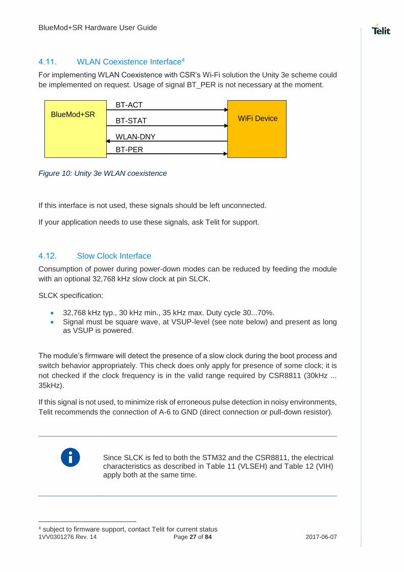
WLAN Coexistence Interface4
For implementing WLAN Coexistence with CSR’s Wi-Fi solution the Unity 3e scheme could
be implemented on request. Usage of signal BT_PER is not necessary at the moment.
BlueMod+SR
WiFi Device
BT-ACT
BT-STAT
WLAN-DNY
BT-PER
Figure 10: Unity 3e WLAN coexistence
If this interface is not used, these signals should be left unconnected.
If your application needs to use these signals, ask Telit for support.
Slow Clock Interface
Consumption of power during power-down modes can be reduced by feeding the module
with an optional 32,768 kHz slow clock at pin SLCK.
SLCK specification:
32,768 kHz typ., 30 kHz min., 35 kHz max. Duty cycle 30...70%.
Signal must be square wave, at VSUP-level (see note below) and present as long as VSUP is powered.
The module’s firmware will detect the presence of a slow clock during the boot process and
switch behavior appropriately. This check does only apply for presence of some clock; it is
not checked if the clock frequency is in the valid range required by CSR8811 (30kHz ...
35kHz).
If this signal is not used, to minimize risk of erroneous pulse detection in noisy environments,
Telit recommends the connection of A-6 to GND (direct connection or pull-down resistor).
Since SLCK is fed to both the STM32 and the CSR8811, the electrical characteristics as described in Table 11 (VLSEH) and Table 12 (VIH) apply both at the same time.
4 subject to firmware support, contact Telit for current status

BlueMod+SR Hardware User Guide
1VV0301276 Rev. 14 Page 28 of 84 2017-06-07
Test Mode
This functionality is reserved. Leave pin TESTMODE# open.
Pin Strapped System Memory Boot Mode Invocation
Asserting BOOT0 “high” will invoke the system memory bootloader at start-up. This is
required for firmware update. Thus, access to this signal and a means to drive it at high
level should be foreseen by the customer’s hardware. While not in use, this signal can be
left open or driven to logic low level.
To connect to the module during system memory boot mode, an RS232 serial interface has
to be directly linked to the UART-TXD (F-4) and UART_RXD (D-2) pins.
The bootloader is stored in the internal boot ROM memory (system memory) of MCU. It is
programmed during production. Its main task is to upgrade the firmware to the internal Flash
memory. A communication protocol is defined with a specific command set and sequences.
The firmware upgrade will be done by either
a Telit provided firmware update tool. This is a Windows™ program that contains the firmware and uses a PC with a serial port for the update
implementing the system memory boot mode protocol on the host system.
If firmware update shall be performed from a host MCU, signals BOOT0 and EXT-RES#
both must be controlled by that host MCU (GPIO ports). Please note that EXT-RES# must
not be driven directly from a push-pull signal (see chapter 4.3).
Operating in a Power Switched Environment
A potential "back feeding" problem may arise, if the module is operated in an environment
where its power supply (VSUP) is switched off by the application. This might be done to
save some power in times Bluetooth is not needed.
As stated in Table 6, the voltage on any I/O pin must not exceed VSUP by more than 0,4V
at any time. Otherwise some current IINJECT flows through the internal protection diodes. This
may damage the module.
There is no problem if the application circuit design and programming can assure that all
signals directed towards BlueMod+SR are set to low (U < 0,3V) before and while VSUP is
turned off. If this is not guaranteed, at least a series resistor (about 1k) must be inserted
into the signal path. This does protect the module but obviously cannot prevent from an
unwanted, additional current flow in case of such signal being at high-level. It may be
necessary to use driver chips in such applications, that gate off these signals while VSUP
is not present.

BlueMod+SR Hardware User Guide
1VV0301276 Rev. 14 Page 29 of 84 2017-06-07
Serial Wire Debug Interface
The Serial Wire interface SWDIO, SWCLK is normally not used in a customer’s product. It
is reserved for debugging purposes.
Leave SWDIO, SWCLK unconnected. Only if you intend to use it for debugging purposes,
make it available and connect SWDIO via a pullup resistor 100kΩ to VSUP (refer to [1]).
Trace Interface 5
The Trace UART TXD interface provides firmware internal trace information and is normally
not used in a customer’s product. In cases where customer support by Telit is requested it
may provide useful information about BlueMod+SR internal states and processes while in
operation. We recommend leaving GPIO[6] unconnected but allowing access to the signal
(e.g. by routing it to a via or a header).
5 subject to firmware support, contact Telit for current status
BlueMod+SR Hardware User Guide
1VV0301276 Rev. 14 Page 30 of 84 2017-06-07
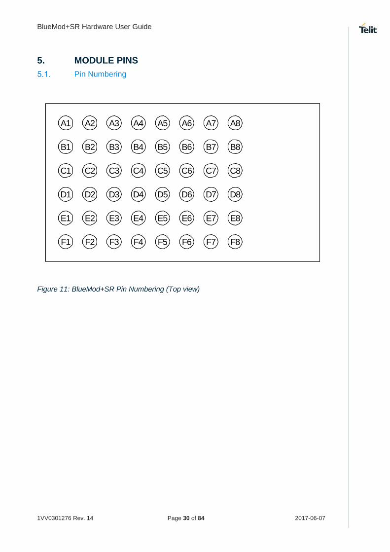
5. MODULE PINS
Pin Numbering
F1
E1
D1
C1
B1
A1 A2 A3 A4 A5 A6 A7 A8
F2
E2
D2
C2
B2
F3
E3
D3
C3
B3
F4
E4
D4
C4
B4
F5
E5
D5
C5
B5
F6
E6
D6
C6
B6
F7
E7
D7
C7
B7
F8
E8
D8
C8
B8
Figure 11: BlueMod+SR Pin Numbering (Top view)

BlueMod+SR Hardware User Guide
1VV0301276 Rev. 14 Page 31 of 84 2017-06-07
General Pin Description
Table 4: General pin assignment
Pin Name Signal Type Act Function Alternate Function
E-6 VSUP1 PWR +3,3V nom.
F-6 VSUP2 PWR +3,3V nom
C-1 VSUP3 PWR(7) +3,3V nom
A-7, E-7, F-7,
B-[5,6,7,8],
C-[5,6,7,8],
D-8, E-8, F-8
GND PWR Ground
A-8 ANT RF n.c. (AI-Variant) RF (AP-Variant)
B-1 EXT-RES# I/O-PU L User Reset
A-6 SLCK I-PD 32,768kHz Slow Clock
F-4 UART-TXD O-PP IUR Data OUT
D-2 UART-RXD I-PD IUR Data IN
D-7 UART-RTS# O-PU (1) L Flow Control/IUC
F-3 UART-CTS# I-PD L Flow Control/IUC
B-4 IUR-OUT# O-PU (1) L UICP Control
D-5 IUR-IN# I-PD L UICP Control
D-3 GPIO[0] I/O (5) GPIO (3) I2C-SCL
B-2 GPIO[1] I/O (5) GPIO (3) I2C-SDA
D-1 GPIO[2] I/O (5) GPIO (3) SPI-MOSI
E-4 GPIO[3] I/O (5) GPIO (3)
D-4 GPIO[4] I/O (5) GPIO (3)
F-2 GPIO[5] I/O (5) GPIO (3) SPI-MISO
C-4 GPIO[6] O-PP TRACE UART TXD
C-3 GPIO[7] I/O (5) GPIO (3)
E-2 GPIO[8] I/O (5) GPIO (3) SPI-SCK
A-3 BT-ACT O WLAN coexistence
A-1 BT-STAT O WLAN coexistence
A-4 WLAN-DNY I-PD WLAN coexistence
A-2 BT-PER O WLAN coexistence
F-1 TESTMODE# I-PU L Testmode
E-1 BOOT0 I-PD (1) System memory bootloader
E-3 SWDIO I-PU (6) serial wire
D-6 SWCLK I-PD serial wire
C-2 DNU (4) reserved
B-3 DNU (4) reserved
A-5 DNU (4) reserved
F-5 DNU (4) reserved
E-5 DNU (4) reserved

BlueMod+SR Hardware User Guide
1VV0301276 Rev. 14 Page 32 of 84 2017-06-07
Type: PU – pull-up; PD – pull-down; PWR – Power; I – Input; O – Output; I/O – bidir.; OD – open drain;
PP – push/pull; RF: RadioFreq
(1) a discrete pull up resistor is used (3) function depends on firmware (4) DNU: Do not use, do not connect (5) GPIO pin. These pins may be programmed as analog-in, i-float, i-pu, i-pd, o-pp (output push/pull), o-od (output
open drain) or some alternate function; refer to [1], [2] (6) if the serial wire interface is used, a pull-up resistor 100kΩ has to be connected to VSUP. Please refer to
chapter 4.16 and [1] (7) Pin C-1 VSUP3 may be left floating for footprint compatibility to other BlueMod+Sx family members
BlueMod+SR Hardware User Guide
1VV0301276 Rev. 14 Page 33 of 84 2017-06-07
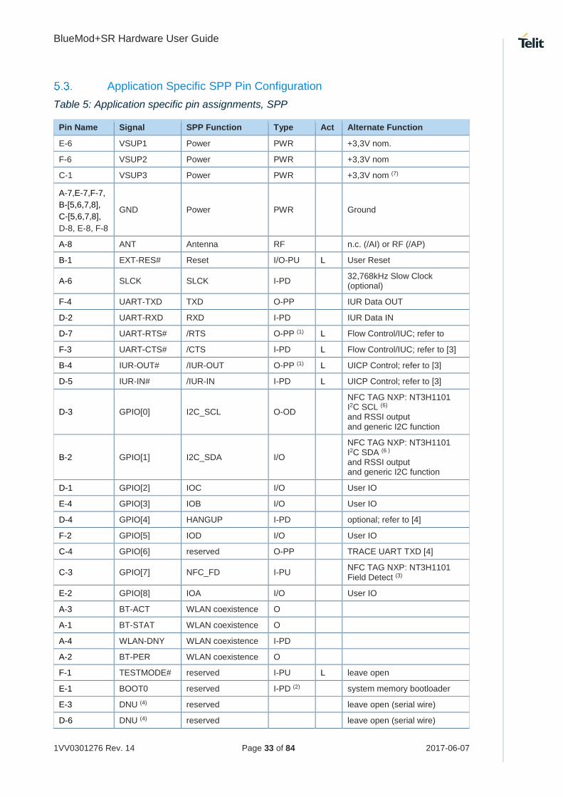
Application Specific SPP Pin Configuration
Table 5: Application specific pin assignments, SPP
Pin Name Signal SPP Function Type Act Alternate Function
E-6 VSUP1 Power PWR +3,3V nom.
F-6 VSUP2 Power PWR +3,3V nom
C-1 VSUP3 Power PWR +3,3V nom (7)
A-7,E-7,F-7,
B-[5,6,7,8],
C-[5,6,7,8],
D-8, E-8, F-8
GND Power PWR Ground
A-8 ANT Antenna RF n.c. (/AI) or RF (/AP)
B-1 EXT-RES# Reset I/O-PU L User Reset
A-6 SLCK SLCK I-PD 32,768kHz Slow Clock (optional)
F-4 UART-TXD TXD O-PP IUR Data OUT
D-2 UART-RXD RXD I-PD IUR Data IN
D-7 UART-RTS# /RTS O-PP (1) L Flow Control/IUC; refer to
F-3 UART-CTS# /CTS I-PD L Flow Control/IUC; refer to [3]
B-4 IUR-OUT# /IUR-OUT O-PP (1) L UICP Control; refer to [3]
D-5 IUR-IN# /IUR-IN I-PD L UICP Control; refer to [3]
D-3 GPIO[0] I2C_SCL O-OD
NFC TAG NXP: NT3H1101 I2C SCL (6) and RSSI output and generic I2C function
B-2 GPIO[1] I2C_SDA I/O
NFC TAG NXP: NT3H1101 I2C SDA (6 ) and RSSI output and generic I2C function
D-1 GPIO[2] IOC I/O User IO
E-4 GPIO[3] IOB I/O User IO
D-4 GPIO[4] HANGUP I-PD optional; refer to [4]
F-2 GPIO[5] IOD I/O User IO
C-4 GPIO[6] reserved O-PP TRACE UART TXD [4]
C-3 GPIO[7] NFC_FD I-PU NFC TAG NXP: NT3H1101 Field Detect (3)
E-2 GPIO[8] IOA I/O User IO
A-3 BT-ACT WLAN coexistence O
A-1 BT-STAT WLAN coexistence O
A-4 WLAN-DNY WLAN coexistence I-PD
A-2 BT-PER WLAN coexistence O
F-1 TESTMODE# reserved I-PU L leave open
E-1 BOOT0 reserved I-PD (2) system memory bootloader
E-3 DNU (4) reserved leave open (serial wire)
D-6 DNU (4) reserved leave open (serial wire)

BlueMod+SR Hardware User Guide
1VV0301276 Rev. 14 Page 34 of 84 2017-06-07
Pin Name Signal SPP Function Type Act Alternate Function
C-2 DNU (4) reserved leave open
B-3 DNU (4) reserved leave open
A-5 DNU (4) reserved leave open
F-5 DNU (4) reserved leave open
E-5 DNU (4) reserved leave open
Type: PU – pull-up; PD – pull-down; PWR – Power; I – Input; O – Output; I/O – bidir.; OD – open drain;
PP – push/pull; RF: RadioFreq
(1) a discrete pull up resistor is used (2) a discrete pull down resistor is used (3) function depends on firmware (4) DNU: Do not use, do not connect (5) If trace feature should be used, this signal has to be made accessible in customer hardware (6) NFC support will be available with SPP FW version V1.500 and higher. Use 4k7 PU each on signals
NFC_SCLK and NFC_SDA (7) Pin C-1 can be left open for BlueMod+S footprint compatibility
Handling of Unused Signals
Depending on the application, not all signals of BlueMod+SR may be needed. The following
list gives some hints how to handle unused signals.
EXT-RES# If no external Reset is needed: Leave open (*)
BOOT0 (*) [leave open]
SLCK If no external slow clock is provided: Leave open or tie
to
GND
UART-RTS#, UART-CTS# If neither flow control nor UICP is used: Leave open
IUR-OUT#, IUR-IN# If UICP is not used: leave open
BT-ACT, BT-STAT, If there is no WLAN device on the same PCB: Leave
open
BT-PER, WLAN-DNY
TESTMODE# Leave open
unused GPIOs Leave open
SWDIO, SWCLK Leave open. Only needed for debug purposes.
GPIO(6) Leave open, connect to via or header pin for getting
debug
TRACE_UART_TXD information in customer hardware
(*) for being able to update the firmware, it is strongly recommended to provide for a means
to set BOOT0 temporarily to logic high level, and to reset the module; see chapter 4.14.

BlueMod+SR Hardware User Guide
1VV0301276 Rev. 14 Page 35 of 84 2017-06-07
6. ELECTRICAL CHARACTERISTICS
Absolute Maximum Ratings
Stresses beyond those listed under “Absolute Maximum Ratings” may cause permanent
damage to the device. These are stress ratings only, and functional operation of the device
at these or any other conditions beyond those indicated under “Electrical Requirements” is
not implied. Exposure to absolute-maximum-rated conditions for extended periods may
affect device reliability.
Table 6: Absolute maximum ratings
Item Symbol Absolute Maximum Ratings Unit
Supply voltage VSUP -0,3 to +3,6 V
Voltage on any pin VPin -0,3 to VSUP +0,4 V
Electrical Requirements
VSUP = 3,3V, Tamb = 25 °C if nothing else stated
Table 7: Electrical requirements
Item Condition Limit Unit
Min Typ Max
Frequency Range 2400 2483.5 MHz
Load impedance Measured with network analyzer in the frequency range at antenna pin
50 Ohm
Output return loss Receive Mode to 50Ω load
Transmit Mode to 50Ω load
-10
-10 dBm
Operating Conditions
Tamb = 25 °C
Table 8: DC operating conditions
Item Condition Limit Unit
Min Typ Max
Supply voltage VSUP 2,5 3,3 3,6 VDC
Environmental Requirements
Table 9: Environmental requirements
Item Symbol Absolute Maximum Ratings Unit
Storage temperature range Tstg -40 to +85 °C
Operating temperature range Top -30 to +85 °C

BlueMod+SR Hardware User Guide
1VV0301276 Rev. 14 Page 36 of 84 2017-06-07
Digital I/O Including EXT-RES#
STM32 MCU and CSR8811 do have different electrical I/O characteristics. All Module I/O
pins are connected directly to these chips without signal conditioning except for some pull-
up/pull-down resistors (as indicated). Therefore the electrical characteristics are split in
different tables.
STM-Related Signals:
EXT-RES# (additional filter-C 100n to GND)
UART-TXD, UART-RXD, UART-CTS#
UART-RTS# (additional pull-up resistor 470kΩ)
IUR-IN#
IUR-OUT# (additional pull-up resistor 470kΩ)
GPIO[0..8], TESTMODE#
BOOT0 (additional pull-down resistor 100kΩ)
Tamb = 25 °C
Table 10: DC characteristics, digital IO (STM32 related)
Symbol Item Condition Limit Unit
Min Typ Max
VIL Low-Level Input Voltage VSUP = 2,5 to 3,6V -0,3 - 0,9 V
VIH High-Level Input Voltage VSUP = 2,5 to 3,6V 2,0 - VSUP+0,3 V
VOL Low-Level Output Voltage IOL = 4mA - - 0,4 V
VOH High-Level Output Voltage IOH = -4mA VSUP-0,4 - - V
IOL Low -Level Output Current VOL = 0,4V - - 8 mA
IOH High-Level Output Current 2,7V < VSUP < 3,6V
VOH > 2.3V - - -8 mA
RPU weak pull-up resistor VIN = VSS 30 40 50 kΩ
RPD weak pull-down resistor VIN = VDD 30 40 50 kΩ
Ilc I/O pad leakage current -3 0 +3 A
Cl Input Capacitance 5 pF

BlueMod+SR Hardware User Guide
1VV0301276 Rev. 14 Page 37 of 84 2017-06-07
External Slow Clock SLCK:
Tamb = 25 °C
Table 11: DC characteristics, SLCK (STM32 backup domain)
Symbol Item Condition Limit Unit
Min Typ Max
VLSEL Low-Level Input Voltage VSUP = 2,5 to 3,6V 0,0 - 0,3 V
VLSEH High-Level Input Voltage VSUP = 2,5 to 3,6V 0,7xVSUP - VSUP V
Ilc I/O pad leakage current VSS ≤ VIN ≤ VSUP -1 - +1 A
Cl Input Capacitance 5 pF
Signal at SLCK is also fed to CSR8811 and has to comply to Table 12, too.
CSR8811 Related Signals:
BT-ACT, BT-STAT, WLAN-DNY, BT-PER
SLCK (caution: also connected to STM-32)
Tamb = 25 °C
Table 12: DC characteristics, digital IO (CSR8811 related)
Symbol Item Condition Limit Unit
Min Typ Max
VIL Low-Level Input Voltage VSUP = 3,3V - 0,4 - 0,4 V
VIH High-Level Input Voltage 0,7xVSUP - VSUP+0,4 V
VOL Low-Level Output Voltage
IOL = 4mA - - 0,4 V
VOH High-Level Output Voltage
IOH = -4mA 0,75xVSUP - - V
Isp-u Input-current Strong pull-up -150 -40 -10 A
Isp-d Input-current Strong pull-down +10 +40 +150 A
Iwp-u Input-current Weak pull-up -5,0 -1,0 -0,33 A
Iwp-d Input-current Weak pull-down +0,33 +1,0 +5,0 A
Ilc I/O pad leakage current n.a. A
Cl Input Capacitance 1,0 - 5,0 pF

BlueMod+SR Hardware User Guide
1VV0301276 Rev. 14 Page 38 of 84 2017-06-07
SLCK is connected to both STM32 and CSR8811 so has to fit to STM32 and CSR8811 requirements at the same time.

BlueMod+SR Hardware User Guide
1VV0301276 Rev. 14 Page 39 of 84 2017-06-07
Power Consumption and Power Down Modes
6.6.1. Classic Bluetooth
The following values are typical power consumption values in the different states.
Table 13: Supply current SPP sleep modes, no radio activity
Condition Note Slow clock SLCK
Current Consumption
Unit
IAvg
Sleep mode, no page scan, no inquiry scan internal
external
3,6
3,5 mA
Deep sleep mode, no page scan, no inquiry scan, UICP active Interface down
(1) internal
external
0,29
0,15 mA
Device in reset (2) (3) 2,7 mA
VSUP = 3,3V, Tamb = 25°C, all GPIOs and UART lines open, SLCK: 32,768 kHz
(1) IUR-IN# and UART-CTS# signals connected to CMOS high level (2) Valid for HW V3, higher in HW Version < 3 (3) Same current consumption w. internal or external slow clock
Table 14: Supply current, SPP Bluetooth Classic
Condition Note Slow clock SLCK
Current Consumption
Unit
IAvg
Standby, page scan & inquiry scan interval 1,28s internal
external
4,2
4,0 mA
Standby, page scan & inquiry scan interval 1,28s,UICP active serial Interface down
(1) internal
external
0,9
0,75 mA
Bluetooth connected, no data traffic (Slave) (2) (3) 14,4 mA
Bluetooth connected, data traffic 115 kbit/s (Slave) (2) (3) 22 mA
Bluetooth connected, no data traffic (Master) (2) (3) 9,3 mA
Bluetooth connected, no data traffic, active sniff using 250 ms sniff interval (Master)
(2) (3) 5,0 mA
Bluetooth connected, no data traffic, active sniff using 250 ms sniff interval, UICP active (Master)
(2) (3) 1,9 mA
Bluetooth connected, no data traffic, active sniff using 500 ms sniff interval (Master)
(2) (3) 4,6 mA
Bluetooth connected, no data traffic, active sniff using 500 ms sniff interval, UICP active (Master)
(2) (3) 1,6 mA
Bluetooth connected, data traffic 115 kbit/s (Master) (2) (3) 20 mA
VSUP = 3,3V, Tamb = 25°C, Tx Power = 7 dBm, all GPIO lines left open, SLCK: 32,768 kHz
(1) IUR-IN# and UART-CTS# signals connected to CMOS high level (2) about 2 meters through the air (3) Same current consumption w. internal or external slow clock

BlueMod+SR Hardware User Guide
1VV0301276 Rev. 14 Page 40 of 84 2017-06-07
6.6.2. LE Configurations
6.6.2.1. LE Operating in Peripheral Device Role
The following tables show the average power consumption of BlueMod+SR in LE-mode
operating in the peripheral device role.
Table 15: Supply current BLE Terminal I/O Profile, peripheral device role, standby
Item Note Slow clock SLCK
Current Consumption
Unit
Tx power (dBm)
max (+7) min (-23)
IAvg IAvg
Standby, Advertising on 3 channels, advertising interval: 1,28s
(5) internal
external
3,9
3,8
3,7
3,7 mA
Standby, Advertising on 3 channels, advertising interval: 1,28s, UICP active serial Interface down
(1) internal
external
0,4
0,25
0,34
0,2 mA
Table 16: Supply current BLE Terminal I/O Profile, peripheral device role, CI 7,5ms
Item Note Slow clock SLCK
Current Consumption
Unit
Tx power (dBm)
max (+7) min (-23)
IAvg IAvg
Connected, connection interval: 7,5 ms, no data traffic (2,3) (6) 9,6 8,8 mA
Connected, connection interval: 7,5 ms, data traffic 115 kbit/s at the serial port, central to peripheral
(2) (6) 24 22 mA
Connected, connection interval: 7,5 ms, data traffic 115 kbit/s at the serial port, peripheral to central
(2) (6) 27 23 mA
Table 17: Supply current BLE Terminal I/O Profile, peripheral device role, CI 37,5ms
Item Note Slow clock SLCK
Current Consumption
Unit
Tx power (dBm)
max (+7) min (-23)
IAvg IAvg
Connected, connection interval: 37,5ms, no data traffic (2,4) internal
external 5,1
5,0
4,9
4,8 mA
Connected, connection interval: 37,5ms, data traffic 115 kbit/s at the serial port, peripheral to central
(2,4) (6) 15,5 14 mA
VSUP = 3,3V, Tamb = 25°C, all GPIO lines left open, SLCK: 32,768 kHz
(1) UART-CTS#, IUR-IN# driven to CMOS high level, all other UART-lines left open (2) Connection parameters are setup by the central device when connection is established (3) No data to be transmitted, central device sends an empty packet (80 bit) then peripheral device answers
(empty packet: 80 bit) (4) These are a typical connection parameters used by an iPhone, iPad or iPad mini device in the central device
role (5) All UART-lines left open (6) Same current consumption w. internal or external slow clock

BlueMod+SR Hardware User Guide
1VV0301276 Rev. 14 Page 41 of 84 2017-06-07
6.6.2.2. LE Operating in Central Device Role
The following tables show the average power consumption of BlueMod+SR in LE-mode
operating in the central device role.
Table 18: Supply current BLE Terminal I/O Profile, central device role, standby
Item Note Slow clock SLCK
Current Consumption
Unit
Tx power (dBm)
max (+7) min (-23)
IAvg IAvg
Standby, scanning for peripherals (6) 50 49 mA
Table 19: Supply current BLE Terminal I/O Profile, central device role, CI 7,5ms
Item Note Slow clock SLCK
Current Consumption
Unit
Tx power (dBm)
max (+7) min (-23)
IAvg IAvg
Connected, connection interval: 7,5 ms, no data traffic (2,3) (6) 10,8 10,1 mA
Connected, connection interval: 7,5 ms, data traffic, data traffic 115 kbit/s at the serial port, central to peripheral
(2) (6) 28 25 mA
Connected, connection interval: 7,5 ms, data traffic, data traffic 115 kbit/s at the serial port, peripheral to central
(2) (6) 25 23 mA
Table 20: Supply current BLE Terminal I/O Profile, central device role, CI 37,5ms
Item Note Slow clock SLCK
Current Consumption
Unit
Tx power (dBm)
max (+7) min (-23)
IAvg IAvg
Connected, connection interval: 37,5ms, no data traffic (2,4) (6) 5,8 5,6 mA
Connected, connection interval: 37,5ms, data traffic 115 kbit/s at the serial port; central to peripheral
(2,4) (6) 16,5 15 mA
VSUP = 3,3V, Tamb = 25°C, all GPIO lines left open, SLCK: 32,768 kHz
(2) Connection parameters are setup by the central device when connection is established (3) No data to be transmitted, central device sends an empty packet (80 bit) then peripheral device answers
(empty packet: 80 bit) (4) These are typical connection parameters used by an iPhone, iPad or iPad mini device in the central device
role (6) Same current consumption w. internal or external slow clock

BlueMod+SR Hardware User Guide
1VV0301276 Rev. 14 Page 42 of 84 2017-06-07
RF Performance
6.7.1. GFSK, PI/4 DQPSK, 8DPSK Receiver
VSUP = 2,5V to 3,6V, Tamb = +20°C
Measured conducted according to BT specification v1.2/2.0/2.0 + EDR/2.1/2.1 +
EDR/3.0/3.0 + HS/4.0
Receiver Frequency [GHz] Limit BT Spec Unit
Min Typ Max
Sensitivity at 0.1% BER DH1
2.402 -84 -80
-70 dBm 2.441 -88 -84
2.480 -88 -84
Sensitivity at 0.1% BER DH5
2.402 -84 -80
-70 dBm 2.441 -88 -84
2.480 -88 -84
Sensitivity at 0.1% BER EDR2, PI/4 DQPSK
2.402 -87 -70
-70 dBm 2.441 -91 -70
2.480 -91 -70
Sensitivity at 0.1% BER EDR3, 8DPSK
2.402 -78 -70
-70 dBm 2.441 -82 -70
2.480 -82 -70
Maximum received signal at 0.1% BER with DH1 -20 0 -20 dBm
Maximum received signal at 0.1% BER with DH5 -20 0 -20 dBm
Maximum received signal at 0.1% BER with EDR2, PI/4 DQPSK
-20 0 -20 dBm
Maximum received signal at 0.1% BER with EDR3, 8DPSK
-20 0 -20 dBm
C/I co-channel GFSK 8 11 11 dB
Adjacent channel selectivity C/I f = f0 + 1MHz GFSK -2 0 0 dB
Adjacent channel selectivity C/I f = f0 - 1MHz GFSK -1 0 0 dB
Adjacent channel selectivity C/I f f0 + 2MHz GFSK -39 -30 -30 dB
Adjacent channel selectivity C/I f f0 - 2MHz GFSK -30 -30 -20 dB
Adjacent channel selectivity C/I f f0 + 3MHz GFSK -45 -40 -40 dB
Adjacent channel selectivity C/I f f0 - 5MHz GFSK -46 -40 -40 dB
Adjacent channel selectivity C/I f = fimage GFSK -25 -9 -9 dB
C/I co-channel PI/4 DQPSK 12 13 13 dB
Adj. channel selectivity C/I f = f0 + 1MHz π/4 DQPSK -7 0 0 dB
Adj. channel selectivity C/I f = f0 - 1MHz π/4 DQPSK -4 0 0 dB
Adj. channel selectivity C/I f f0 + 2MHz π/4 DQPSK -40 -30 -30 dB
Adj. channel selectivity C/I f f0 - 2MHz π/4 DQPSK -36 -20 -20 dB
Adj. channel selectivity C/I f f0 + 3MHz π/4 DQPSK -48 -40 -40 dB
Adj. channel selectivity C/I f f0 - 5MHz π/4 DQPSK -50 -40 -40 dB
Adj. channel selectivity C/I f = fimage π/4 DQPSK -22 -7 -7 dB

BlueMod+SR Hardware User Guide
1VV0301276 Rev. 14 Page 43 of 84 2017-06-07
Receiver Frequency [GHz] Limit BT Spec Unit
Min Typ Max
C/I co-channel 8DPSK 18 21 21 dB
Adj. channel selectivity C/I f = f0 + 1MHz 8DPSK -4 5 5 dB
Adj. channel selectivity C/I f = f0 - 1MHz 8DPSK -1 5 5 dB
Adj. channel selectivity C/I f f0 + 2MHz 8DPSK -36 -25 -25 dB
Adj. channel selectivity C/I f f0 - 2MHz 8DPSK -31 -13 -13 dB
Adj. channel selectivity C/I f f0 + 3MHz 8DPSK -42 -33 -33 dB
Adj. channel selectivity C/I f f0 - 5MHz 8DPSK -43 -33 -33 dB
Adj. channel selectivity C/I f = fimage 8DPSK -14 0 -0 dB
VSUP = 2,5V to 3,6V, Tamb = -30°C
Measured conducted according to BT specification v1.2/2.0/2.0 + EDR/2.1/2.1 +
EDR/3.0/3.0 + HS/4.0
Receiver Frequency [GHz] Limit BT Spec Unit
Min Typ Max
Sensitivity at 0.1% BER DH1
2.402 -84 -80
-70 dBm 2.441 -88 -84
2.480 -88 -84
Sensitivity at 0.1% BER DH5
2.402 -84 -80
-70 dBm 2.441 -88 -84
2.480 -88 -84
Sensitivity at 0.1% BER EDR2, PI/4 DQPSK
2.402 -88 -70
-70 dBm 2.441 -91 -70
2.480 -91 -70
Sensitivity at 0.1% BER EDR3, 8DPSK
2.402 -78 -70
-70 dBm 2.441 -82 -70
2.480 -82 -70
Maximum received signal at 0.1% BER DH1 -20 0 -20 dBm
Maximum received signal at 0.1% BER PI/4 DQPSK -20 0 -20 dBm
Maximum received signal at 0.1% BER 8DPSK -20 0 -20 dBm

BlueMod+SR Hardware User Guide
1VV0301276 Rev. 14 Page 44 of 84 2017-06-07
VSUP = 2,5V to 3,6V, Tamb = +85°C
Measured conducted according to BT specification v1.2/2.0/2.0 + EDR/2.1/2.1 +
EDR/3.0/3.0 + HS/4.0
Receiver Frequency [GHz] Limit BT Spec Unit
Min Typ Max
Sensitivity at 0.1% BER DH1
2.402 -84 -80
-70 dBm 2.441 -88 -84
2.480 -88 -84
Sensitivity at 0.1% BER DH5
2.402 -84 -80
-70 dBm 2.441 -88 -84
2.480 -88 -84
Sensitivity at 0.1% BER EDR2, PI/4 DQPSK
2.402 -87 -70
-70 dBm 2.441 -90 -70
2.480 -90 -70
Sensitivity at 0.1% BER EDR3, 8DPSK
2.402 -78 -70
-70 dBm 2.441 -80 -70
2.480 -80 -70
Maximum received signal at 0.1% BER DH1 -20 0 -20 dBm
Maximum received signal at 0.1% BER PI/4 DQPSK -20 0 -20 dBm
Maximum received signal at 0.1% BER 8DPSK -20 0 -20 dBm
For calculating true performance add product specific antenna gain.

BlueMod+SR Hardware User Guide
1VV0301276 Rev. 14 Page 45 of 84 2017-06-07
6.7.2. GFSK, PI/4 DQPSK, 8DPSK Transmitter
VSUP = 2,5V to 3,6V, Tamb = +20°C
Measured conducted according to BT specification v1.2/2.0/2.0 + EDR/2.1/2.1 +
EDR/3.0/3.0 + HS/4.0
Receiver Frequency [GHz] Limit BT Spec Unit
Min Typ Max
RF transmit power
50 Ω load, at antenna
Class 1 device GFSK b)
2.402 2,7 5,5
0 to 20 dBm 2.441 4,7 7,5
2.480 5,7 8,5
RF transmit power
50 Ω load, at antenna
Class 1 device EDR2, π/4 DQPSK b)
2.402 GFSK 2,0
∆TX = -4 to 1
dBm
2.402 π/4 DQPSK 0,9
2.441 GFSK 4,7
2.441 π/4 DQPSK 3,7
2.480 GFSK 5,6
2.480 π/4 DQPSK 4,6
RF transmit power
50 Ω load, at antenna
Class 1 device EDR3, 8DPSK b)
2.402 GFSK 2,1
∆TX = -4 to 1
dBm
2.402 8DPSK 1,0
2.441 8GFSK 4,8
2.441 8DPSK 3,7
2.480 GFSK 5,6
2.480 8DPSK 4,6
RF power control range 16 30 ≥16 dB
RF power range control resolution 2 4 8 2 to 8 dB
20 dB bandwidth for modulated carrier 925 1000 1000 kHz
ICFT -75 ±25 +75 75 kHz
Carrier frequency drift (packet DH1) 7 25 25 kHz
Drift Rate 5 20 ≤ 20 kHz/ 50µs
f1avg “Maximum Modulation” 140 164 175 140 to
175 kHz
f2max “Minimum Modulation” 115 140 >115 kHz
f2avg /f1avg 0,8 0,91 0,8

BlueMod+SR Hardware User Guide
1VV0301276 Rev. 14 Page 46 of 84 2017-06-07
VSUP = 2,5V to 3,6V, Tamb = -30°C
Measured conducted according to BT specification v1.2/2.0/2.0 + EDR/2.1/2.1 +
EDR/3.0/3.0 + HS/4.0
Receiver Frequency [GHz] Limit BT Spec Unit
Min Typ Max
RF transmit power
50 Ω load, at antenna
Class 1 device GFSK
2.402 2,7 3,5
0 to 20 dBm 2.441 4,7 6,5
2.480 5,7 7,5
RF transmit power
50 Ω load, at antenna
Class 1 device EDR2, π/4 DQPSK
2.402 GFSK -0,5
∆TX = -4 to 1
dBm
2.402 π/4 DQPSK -1,9
2.441 GFSK 2,5
2.441 π/4 DQPSK 1,2
2.480 GFSK 4,0
2.480 π/4 DQPSK 2,8
RF transmit power
50 Ω load, at antenna
Class 1 device EDR3, 8DPSK
2.402 GFSK -0,5
∆TX = -4 to 1
dBm
2.402 8DPSK -1,7
2.441 GFSK 2,5
2.441 8DPSK 1,2
2.480 GFSK 4,0
2.480 8DPSK 2,8
20 dB bandwidth for modulated carrier 925 1000 1000 kHz
Initial carrier frequency tolerance -75 10 +75 75 kHz
Carrier frequency drift (packet DH1) 6 25 25 kHz
Drift Rate 5 20 20 kHz/ 50µs
f1avg “Maximum Modulation” 140 164 175 140 to
175 kHz
f2max “Minimum Modulation” 115 142 115 kHz
f2avg /f1avg 0,8 0,92 0,8
BlueMod+SR Hardware User Guide
1VV0301276 Rev. 14 Page 47 of 84 2017-06-07
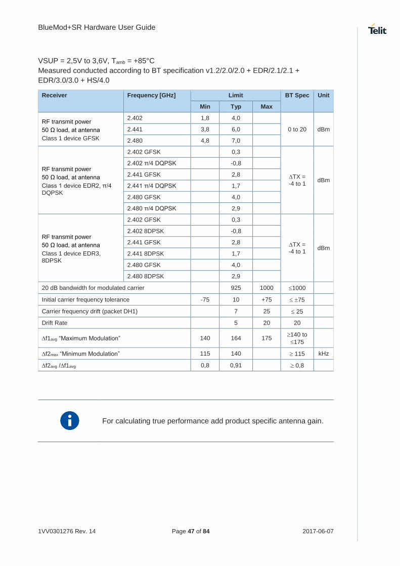
VSUP = 2,5V to 3,6V, Tamb = +85°C
Measured conducted according to BT specification v1.2/2.0/2.0 + EDR/2.1/2.1 +
EDR/3.0/3.0 + HS/4.0
Receiver Frequency [GHz] Limit BT Spec Unit
Min Typ Max
RF transmit power
50 Ω load, at antenna
Class 1 device GFSK
2.402 1,8 4,0
0 to 20 dBm 2.441 3,8 6,0
2.480 4,8 7,0
RF transmit power
50 Ω load, at antenna
Class 1 device EDR2, π/4 DQPSK
2.402 GFSK 0,3
∆TX = -4 to 1
dBm
2.402 π/4 DQPSK -0,8
2.441 GFSK 2,8
2.441 π/4 DQPSK 1,7
2.480 GFSK 4,0
2.480 π/4 DQPSK 2,9
RF transmit power
50 Ω load, at antenna
Class 1 device EDR3, 8DPSK
2.402 GFSK 0,3
∆TX = -4 to 1
dBm
2.402 8DPSK -0,8
2.441 GFSK 2,8
2.441 8DPSK 1,7
2.480 GFSK 4,0
2.480 8DPSK 2,9
20 dB bandwidth for modulated carrier 925 1000 1000
Initial carrier frequency tolerance -75 10 +75 75
Carrier frequency drift (packet DH1) 7 25 25
Drift Rate 5 20 20
f1avg “Maximum Modulation” 140 164 175 140 to
175
f2max “Minimum Modulation” 115 140 115 kHz
f2avg /f1avg 0,8 0,91 0,8
For calculating true performance add product specific antenna gain.

BlueMod+SR Hardware User Guide
1VV0301276 Rev. 14 Page 48 of 84 2017-06-07
6.7.3. BLE Receiver
VSUP = 2,5V to 3,6V, Tamb = +20°C
Measured conducted according to BT specification RF-PHY.TS/4.0.1
Receiver Frequency [GHz] Min Typ Max BT Spec Unit
Sensitivity at 30,8% PER
2,402 -87 -83
≤ -70 dBm 2,440 -90 -86
2,480 -90 -86
Reported PER during PER report integrity test
2,426 50 50 65,4 50
< PER < 65,4
%
Maximum received signal at 30,8% PER -10 0 ≥ -10 dBm
Continuous power required to block Bluetooth reception at -67dBm with 0,1%PER
0,030 - 2,000 -30 > 0 -30
dBm 2,000 - 2,400 -35 0 -35
2,500 -3,000 -35 0 -35
3,000 . 12,75 -30 >0 -30
C/I co-channel 8 21 ≤21 dB
Adjacent channel Selectivity C/I
F = F0 + 1 MHz 1 15 ≤15 dB
F = F0 - 1 MHz -9 15 ≤15 dB
F = F0 + 2 MHz -27 -17 ≤-17 dB
F = F0 - 2 MHz -19 -15 ≤-15 dB
F = F0 + 3 MHz -43 -27 ≤-27 dB
F = F0 - 5 MHz -49 -27 ≤-27 dB
F = Fimage -24 -9 ≤-9 dB
Maximum level of intermodulation interferers -50 -18 ≥-50 dBm
VSUP = 2,5V to 3,6V, Tamb = -30°C
Measured conducted according to BT specification RF-PHY.TS/4.0.1
Receiver Frequency [GHz] Min Typ Max BT Spec Unit
Sensitivity at 30,8% PER
2,402 -87 -83
≤ -70 dBm 2,440 -90 -87
2,480 -90 -87
Reported PER during PER report integrity test
2,426 50 50 65,4 50
< PER < 65,4
%
Maximum received signal at 30,8% PER -10 0 ≥ -10 dBm

BlueMod+SR Hardware User Guide
1VV0301276 Rev. 14 Page 49 of 84 2017-06-07
VSUP = 2,5V to 3,6V, Tamb = +85°C
Measured conducted according to BT specification RF-PHY.TS/4.0.1
Receiver Frequency [GHz] Min Typ Max BT Spec Unit
Sensitivity at 30,8% PER
2,402 -87 -83
≤ -70 dBm 2,440 -89 -85
2,480 -89 -85
Reported PER during PER report integrity test 2,426 50 50 65,4
50 < PER < 65,4
%
Maximum received signal at 30,8% PER -10 0 ≥ -10 dBm

BlueMod+SR Hardware User Guide
1VV0301276 Rev. 14 Page 50 of 84 2017-06-07
6.7.4. BLE Transmitter
VSUP = 2,5V to 3,6V, Tamb = +20°C
Measured conducted according to BT specification RF-PHY.TS/4.0.1
Receiver Frequency [GHz] Min Typ Max BT Spec Unit
RF Transmit Power
2,402 2,0 5,5 10
-20 to +10
dBm 2,440 4,0 7,5 10
2,480 5,0 8,5 10
ACP
F = F0 ± 2MHz -28 -20 ≤ -30
dBm F = F0 ± 3MHz -38 -30 ≤ -30
F = F0 ± > 3MHz <-60 -30 ≤ -30
∆f1avg maximum modulation 225 268 275 225
< f1avg < 275
kHz
∆f2max minimum modulation 185 214 ≥ 185 kHz
∆f2avg / ∆f1avg 0,8 0,83 ≥ 0,8
Frequency Offset -95 ±25 +95 ± 150 kHz
Carrier drift rate 4 20 ≤ 20 kHz/ 50µs
Carrier drift 5 50 ≤ 50 kHz
VSUP = 2,5V to 3,6V, Tamb = -30°C
Measured conducted according to BT specification RF-PHY.TS/4.0.1
Receiver Frequency [GHz] Min Typ Max BT Spec Unit
RF transmit Power 2,402 0,5 4,0 10
-20 to +10
dBm 2,440 2,5 6,5 10
2,480 3,5 7,5 10
ACP
F = F0 ± 2MHz -28 -20 ≤ -30
dBm F = F0 ± 3MHz -35 -30 ≤ -30
F = F0 ± > 3MHz <-60 -30 ≤ -30
∆f1avg maximum modulation 225 266 275
225 < f1avg < 275
kHz
∆f2max minimum modulation 185 225 ≥ 185 kHz
∆f2avg / ∆f1avg 0,8 0,85 ≥ 0,8
Frequency Offset -95 ±25 +95 ± 150 kHz
Carrier drift rate 4 20 ≤ 20
kHz/ 50µs
Carrier drift 5 50 ≤ 50 kHz
BlueMod+SR Hardware User Guide
1VV0301276 Rev. 14 Page 51 of 84 2017-06-07
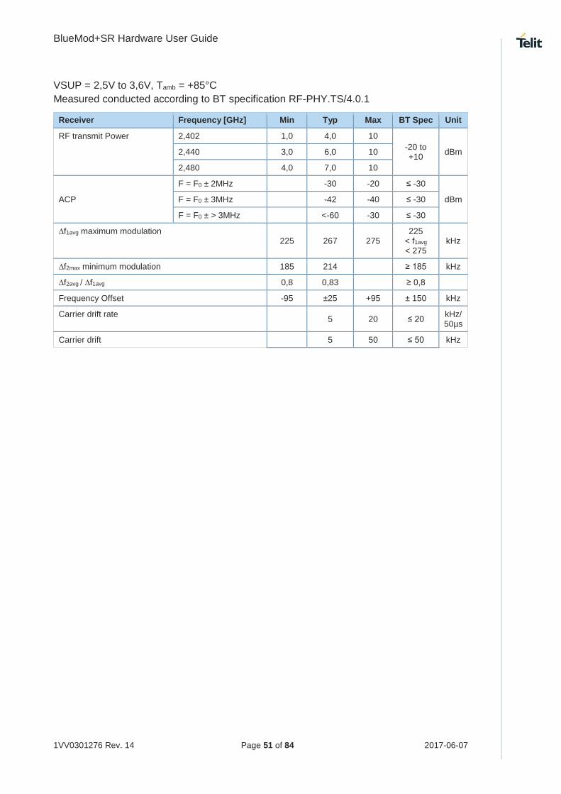
VSUP = 2,5V to 3,6V, Tamb = +85°C
Measured conducted according to BT specification RF-PHY.TS/4.0.1
Receiver Frequency [GHz] Min Typ Max BT Spec Unit
RF transmit Power 2,402 1,0 4,0 10
-20 to +10
dBm 2,440 3,0 6,0 10
2,480 4,0 7,0 10
ACP
F = F0 ± 2MHz -30 -20 ≤ -30
dBm F = F0 ± 3MHz -42 -40 ≤ -30
F = F0 ± > 3MHz <-60 -30 ≤ -30
∆f1avg maximum modulation 225 267 275
225 < f1avg < 275
kHz
∆f2max minimum modulation 185 214 ≥ 185 kHz
∆f2avg / ∆f1avg 0,8 0,83 ≥ 0,8
Frequency Offset -95 ±25 +95 ± 150 kHz
Carrier drift rate 5 20 ≤ 20
kHz/ 50µs
Carrier drift 5 50 ≤ 50 kHz

BlueMod+SR Hardware User Guide
1VV0301276 Rev. 14 Page 52 of 84 2017-06-07
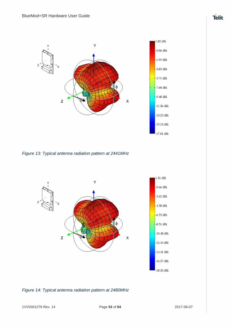
6.7.5. Antenna Gain and Radiation Pattern
If BlueMod+SR/AI is integrated into an end product while the recommendations depicted in
7.4 Placement Recommendation are maintained, the following typical antenna radiation
patterns can be expected.
Radiation Pattern will depend on the end products PCB size, masses in the antenna
environment, housing material and geometrics.
Figure 12: Typical antenna radiation pattern at 2402MHz
Y
XZ
BlueMod+SR Hardware User Guide
1VV0301276 Rev. 14 Page 53 of 84 2017-06-07
Figure 13: Typical antenna radiation pattern at 2441MHz
Figure 14: Typical antenna radiation pattern at 2480MHz
Y
XZ
Y
XZ

BlueMod+SR Hardware User Guide
1VV0301276 Rev. 14 Page 54 of 84 2017-06-07
Power-Up Time
The time until the BlueMod+SR is able to accept link requests or serial data depends on the
firmware version. In the SPP firmware the module is command ready and Bluetooth links
are accepted at least 1,1 s after signal EXT-RES# is de-asserted or VSUPx is in a valid
range.
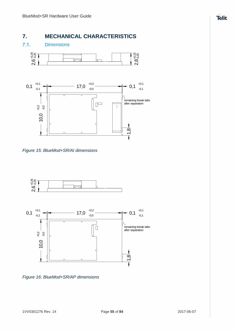
BlueMod+SR Hardware User Guide
1VV0301276 Rev. 14 Page 55 of 84 2017-06-07
7. MECHANICAL CHARACTERISTICS
Dimensions
17,0+0,2
-0,0
10,0
+0,2
-0,0
0,1+0,1
-0,10,1
+0,1
-0,1
remaining break tabsafter separation
1,8
2,8
+0,2
5-0
,25
2,6
+0,2
5-0
,25
Figure 15: BlueMod+SR/AI dimensions
17,0+0,2
-0,0
10,0
+0,2
-0,0
0,1+0,1
-0,10,1
+0,1
-0,1
remaining break tabsafter separation
1,8
2,6
+0,2
5-0
,25
Figure 16: BlueMod+SR/AP dimensions

BlueMod+SR Hardware User Guide
1VV0301276 Rev. 14 Page 56 of 84 2017-06-07
Recommended Land Pattern
F1
E1
D1
C1
B1
A1 A2 A3 A4 A5 A6 A7 A8
F2
E2
D2
C2
B2
F3
E3
D3
C3
B3
F4
E4
D4
C4
B4
F5
E5
D5
C5
B5
F6
E6
D6
C6
B6
F7
E7
D7
C7
B7
F8
E8
D8
C8
B8
1,2
5
1,25
7x1,5=10,5
5x1
,5=7,5
0,9
Figure 17: BlueMod+SR land pattern TOP VIEW
All dimensions are in mm.

BlueMod+SR Hardware User Guide
1VV0301276 Rev. 14 Page 57 of 84 2017-06-07
Re-flow Temperature Time Profile
The data here is given only for guidance on solder and has to be adapted to your process
and other re-flow parameters for example the used solder paste. The paste manufacturer
provides a re-flow profile recommendation for his product.
Figure 18: Soldering temperature time profile (for reflow soldering)
Preheat Main Heat Peak
tsmax tLmax tpmax
Temperature Time Temperature Time Temperature Time
[°C] [sec] [°C] [sec] [°C] [sec]
150 100 217 90 260 10
230 50
Average ramp-up rate [°C / sec] 3
Average ramp-down rate [°C / sec] 6
Max. Time 25°C to Peak Temperature
[min.] 8
Opposite side re-flow is prohibited due to module weight.
Devices will withstand the specified profile and will withstand up to 1 re-flows to a maximum
temperature of 260°C. The reflow soldering profile may only be applied if the BlueMod+SR
resides on the PCB side looking up. Heat above the solder eutectic point while the
BlueMod+SR is mounted facing down may damage the module permanently.

BlueMod+SR Hardware User Guide
1VV0301276 Rev. 14 Page 58 of 84 2017-06-07
Placement Recommendation
To achieve best radio performance for BlueMod+SR/AI, it is recommended to use the
placement shown in Figure 19. This is a “corner placement” meaning the BlueMod+SR is
placed such that the antenna comes close to the corner of the application PCB (red area).
So, the yellow area is outside the PCB and regards to the housing, too (refer to 7.5).
Please note that for best possible performance the antenna should be directed away from
the application PCB as shown in Figure 19.
max.0,5
4,5
10
10
max.
0,5
10
15
no bare copper (exept solder pads for module)
no copper and components on any layer
no components on any layer
provide solid ground plane(s) as large as possible around
17
do not place any conductive parts in this area20
20
40
area
Applic. PCB
Figure 19: BlueMod+SR/AI placement recommendations
Housing Guidelines
The individual case must be checked to decide whether a specific housing is suitable for
the use of the internal antenna. A plastic housing must at least fulfill the following
requirements:
Non-conductive material, non-RF-blocking plastics
No metallic coating
ABS is suggested

BlueMod+SR Hardware User Guide
1VV0301276 Rev. 14 Page 59 of 84 2017-06-07
Antenna Issues
BlueMod+SR is shipped with 2 different antenna designs:
BlueMod+SR/AI comprises a ceramic antenna which as a component is soldered to
the circuit board. This is functional for a BlueMod+SR/AI integrated into a plastic
housing. No additional antenna is required.
For an external antenna to be set in, e.g. because the BlueMod+SR is integrated into a
metal housing, the ceramic antenna is replaced.
BlueMod+SR/AP routes the antenna signal to pin A-8.
The gain of the external antenna shall not exceed +2dBi.
When using an external Antenna the antenna must be fixed and shall not be removable or
replaceable by the end user. In any case, the performance of the antenna (whether it is
internal or external) has to be checked within the final integration environment. Adjacent
PCBs, components, cables, housings etc. could otherwise influence the radiation pattern or
be influenced by the radio wave energy.
It must be ensured that the antenna is not co-located or operating in conjunction with any
other antennas, transmitters, cables or connectors. When the internal ceramic antenna is
used, certain restrictions are to be considered.
Safety Guidelines
According to SAR regulation EN 62479:2010 the BlueMod+SR is not intended to be used
in close proximity to the human body. Please refer to above mentioned regulation for more
specific information.
In respect to the safety regulation EN60950-1: 2006 + A11: 2009 + A1: 2010 + AC:2011 all
conductive parts of the BlueMod+SR are to be classified as SELV circuitry. OEM’s
implementing the BlueMod+SR in their products should follow the isolation rules given in
regulation EN 60950-1: 2006.
The PCB material of the BlueMod+SR is classified UL-94V0.
Cleaning
In general, cleaning the modules mounted on the host board is strongly discouraged.
Residues between module and host board cannot be easily removed with any cleaning
method.
Cleaning with water or any organic solvent can lead to capillary effects where the
cleaning solvent is absorbed into the gap between the module and the host board.
The combination of soldering flux residues and encapsulated solvent could lead to
short circuits between conductive parts. The solvent could also damage any labels.
Ultrasonic cleaning could damage the module permanently. Especially for crystal
oscillators the risk of damaging is very high.

BlueMod+SR Hardware User Guide
1VV0301276 Rev. 14 Page 60 of 84 2017-06-07
8. APPLICATION DIAGRAM
The following schematic shows a typical application of BlueMod+SR. The module is
connected to some MCU running the application layer. MCU and BlueMod+SR use the
same 3,3V power supply. Provisions are made for upgrading the firmware (BOOT0 and
EXT-RES# are managed by the MCU). The serial interface has RTS/CTS flow control but
no UICP support in this example. The Hangup feature to close down the link is provided.
As an option to save power, there is an external slow clock oscillator. All other module pins
may be left unconnected.
Host MCU
VDD
GND
+3V3
GPIO (o)
In this example BlueMod+SR is connected to an MCU supporting RTS/CTS flow control and Hangup.Firmware update is supported (BOOT0, EXT-RES# connected).The slow clock oscillator (32,768kHz ) is optional; it helps to save power during power down states.
1k
BlueMod+SRC-1,E-6,F-6
VSUP
GND
B-1 EXT-RES#
BOOT0GPIO (o)
UART-RXD
UART-TXD
UART-CTS#
UART-RTS#
GPIO[4]/Hangup
TXD (o)RXD (i)
RTS# (o)CTS# (i)
GPIO (o)
SLCK
32,768kHz square
+3V3
The oscillator is optional. Leave A-6 openor tie to GND if the oscillator is not present.
E-1
D-2
F-4
F-3
D-7
D-4
A-6
all GND pads (14) must be connected.Blocking capacitors not shown.
pushpull or OD
pushpull
pushpull
Figure 20: Typical application schematics
BlueMod+SR Hardware User Guide
1VV0301276 Rev. 14 Page 61 of 84 2017-06-07
9. APPROVALS/CERTIFICATIONS
The BlueMod+SR/AI has been tested to comply to the appropriate EU, FCC and IC
directives.
CE testing is intended for end products only. Therefore CE testing is not mandatory for a
Bluetooth Module sold to OEM’s. However Telit provides CE tested modules for customers
in order to ease CE compliance assessment of end products and to minimize test effort.
Declaration of Conformity CE
The BlueMod+SR/AI or /AP fully complies with the essential requirements of the following
EU directives:
RED 2014/53/EU (Variant /AP for external antennas with less than +2dBi gain)
RoHS 2011/65/EC
The actual version of EU Declaration of Conformity (EU DoC) can be downloaded from
http://www.telit.com/RED
FCC Compliance
The BlueMod+SR/AI has been tested to fulfill the FCC requirements. Test reports are
available on request. Grants of the Full Modular Approval will be shown below.
BlueMod+SR/AP only:
For selling products implementing the BlueMod+SR/AP in the USA you’ll have to apply for
a Class II Permissive Change from the FCC authorities. Depending on antenna gain and
other factors the FCC TCB will issue a reduced test plan for re-testing. Telit can assist
customers with conducting this procedure on request. Especially the test plan reduction and
cost optimization may be items worth to look at.

BlueMod+SR Hardware User Guide
1VV0301276 Rev. 14 Page 62 of 84 2017-06-07
9.2.1. FCC Grant

BlueMod+SR Hardware User Guide
1VV0301276 Rev. 14 Page 63 of 84 2017-06-07

BlueMod+SR Hardware User Guide
1VV0301276 Rev. 14 Page 64 of 84 2017-06-07
9.2.2. FCC Statement
This device complies with 47 CFR Part 2 and Part 15 of the FCC Rules and with.
Operation is subject to the following two conditions:
(1) This device my not cause harmful interference, and
(2) This device must accept any interference received, including interference that may
cause undesired operation.
9.2.3. FCC Caution
Warning:
Changes or modifications made to this equipment not expressly approved by Telit may void the FCC authorization to operate this equipment.
9.2.4. FCC Warning
This equipment has been tested and found to comply with the limits for a Class B digital
device, pursuant to Part 15 of the FCC Rules. These limits are designed to provide
reasonable protection against harmful interference in a residential installation. This
equipment generates, uses and can radiate radio frequency energy and, if not installed and
used in accordance with the instructions, may cause harmful interference to radio
communications. However, there is no guarantee that interference will not occur in a
particular installation. If this equipment does cause harmful interference to radio or
television reception, which can be determined by turning the equipment off and on, the user
is encouraged to try to correct the interference by one or more of the following measures:
Reorient or relocate the receiving antenna.
Increase the separation between the equipment and receiver.
Connect the equipment into an outlet on a circuit different from that to which the
receiver is connected.
Consult the dealer or an experienced radio/TV technician for help.
9.2.5. FCC RF-exposure Statement
The BlueMod+SR/AI complies with the FCC/IC RF radiation exposure limits set forth for an
uncontrolled environment.
The output power is < 10mW EIRP and therefore according to “FCC KDB 447498 D01
General RF Exposure Guidance v05” Appendix A, table “SAR Exclusion Threshold”,
excluded from SAR testing for test separation distances ≥5mm and if it is not used in co-
locations with other antennas. If the product implementing the BlueMod+SR/AI has other

BlueMod+SR Hardware User Guide
1VV0301276 Rev. 14 Page 65 of 84 2017-06-07
antennas in co-location or separation distances < 5mm an FCC TCB should be asked for a
Class II Permissive Change.
RF exposure evaluation of devices implementing the BlueMod+SR/AP should be done with
the collaboration of the FCC TCB working on the Class II Permissive Change Request.
9.2.6. FCC Labeling Requirements for the End Product
Any End Product integrating the BlueMod+SR/AI or /AP must be labeled with at least the
following information:
This device contains transmitter with
FCC ID: RFRMSR
IC: 4957A-MSR
IC Compliance
The BlueMod+SR/AI has been tested to fulfill the IC requirements. Test reports RSS-210 of
Industry Canada are available on request. Grants of the Full Modular Approval will be shown
below.
For selling products implementing the BlueMod+SR/AP in Canada you’ll have to apply for
a Class II Permissive Change from the IC authorities. Depending on antenna gain and other
factors the IC TCB will issue a reduced test plan for re-testing. Telit can assist customers
with conducting this procedure on request. Especially the test plan reduction and cost
optimization may be items worth to look at.

BlueMod+SR Hardware User Guide
1VV0301276 Rev. 14 Page 66 of 84 2017-06-07
9.3.1. IC Grant
BlueMod+SR Hardware User Guide
1VV0301276 Rev. 14 Page 67 of 84 2017-06-07
9.3.2. IC Statement
(i) Ce dispositif doit être installé et exploité dans une enceinte entièrement fermée afin de
prévenir les rayonnements RF qui pourraient autrement perturber la navigation
aéronautique. L’installation doit être effectuée par des installateurs qualifiés, en pleine
conformité avec les instructions du fabricant.
(ii) Ce dispositif ne peut être exploité qu'en régime de non-brouillage et de non-protection,
c’est-à-dire que l’utilisateur doit accepter que des radars de haute puissance de la même
bande de fréquences puissent brouiller ce dispositif ou même l’endommager. D’autre part,
les capteurs de niveau à propos desquels il est démontré qu’ils perturbent une exploitation
autorisée par licence de fonctionnement principal doivent être enlevés aux frais de leur
utilisateur.
This device complies with Industry Canada license-exempt RSS standard(s).
Operation is subject to the following two conditions:
(1) This device may not cause interference, and
(2) This device must accept any interference, including interference that may cause
undesired operation of the device.
NOTICE:
This Class B digital apparatus complies with Canadian ICES-003.
Cet appareil numérique de la classe B est conforme à la norme NMB-003 du Canada.
9.3.3. IC Caution
Warning:
Changes or modifications made to this equipment not expressly approved by Telit may void the IC authorization to operate this equipment.
9.3.4. IC RF-exposure Statement
This equipment is portable device. The output power of this device is less than 20mW.
The SAR test is not required.
RF exposure evaluation of devices implementing the BlueMod+SR/AP should be done with
the collaboration of the IC TCB working on the Class II Permissive Change Request

BlueMod+SR Hardware User Guide
1VV0301276 Rev. 14 Page 68 of 84 2017-06-07
9.3.5. IC Labeling Requirements for the End Product
Any end product integrating the BlueMod+SR/AI or /AP must be labeled with at least the
following information:
This device contains transmitter with
FCC ID: RFRMSR
IC-ID: 4957A-MSR
9.3.6. IC Label Information BlueMod+SR
The BlueMod+SR shows no IC-ID on the product label, because there is no space available.
IC allows on request to state the IC-ID in the product manual. This product has been granted
to do so.
Model: BlueMod+SR
The IC-ID is: 4957A-MSR

BlueMod+SR Hardware User Guide
1VV0301276 Rev. 14 Page 69 of 84 2017-06-07
KC Certification
The BlueMod+SR/AI has been certified in Korea under the Clause 2, Article 58-2 of Radio
Waves Act. Certificate is shown below with MSIP-CRM-Rfr-BlueModSR.
9.4.1. KC Certificate

BlueMod+SR Hardware User Guide
1VV0301276 Rev. 14 Page 70 of 84 2017-06-07
MIC Certification
The BlueMod+SR has been tested to fulfill the Japanese MIC requirements.
Please note that the Japanese Certificates are only valid for the variants using the internal ceramic antenna, denoted by the string “AI” in the product name.
BlueMod+SR modules designed for the use with an external antenna, denoted by the string “AP” in the product name, do need extra procedures if another antenna than in the following list of Approved External Antennas is intended to be used.
Every new antenna configuration requires an administrative Japanese Re-certification with
reduced costs. For using another antenna with variant BlueMod+SR/AP, please contact
Telit for starting the Japanese administrative process. Costs for re-measurements and
certification should be considered.
Manufacturer Part Number Gain Connector Approval
WIMO 17010.11REV 2 dBi Reverse SMA MIC
Japanese Radio Law
日本の電気通信事業法と電気通信事業法の基準
This device is granted pursuant to the Japanese Radio Law (電波法)
本製品は、電波法と電気通信事業法に基づく適合証明を受けております。
This device should not be modified (otherwise the granted designation number will become
invalid)
本製品の改造は禁止されています。(適合証明番号などが無効となります。)

BlueMod+SR Hardware User Guide
1VV0301276 Rev. 14 Page 71 of 84 2017-06-07
9.5.1. MIC Certificates

BlueMod+SR Hardware User Guide
1VV0301276 Rev. 14 Page 72 of 84 2017-06-07

BlueMod+SR Hardware User Guide
1VV0301276 Rev. 14 Page 73 of 84 2017-06-07
Anatel Certification
The BlueMod+SR/AI has been certified in Brazil by Anatel.

BlueMod+SR Hardware User Guide
1VV0301276 Rev. 14 Page 74 of 84 2017-06-07
Bluetooth Qualification
The BlueMod+SR is a qualified design according to the Bluetooth Qualification Program
Reference Document (PRD) V2.3.
The Declaration ID is: B021281
The Qualified Design ID is: 44784
For further information about marking requirements of your product attention should be paid
the Bluetooth Brand Usage Guide at
https://www.bluetooth.org/en-us/bluetooth-brand/bluetooth-brand
According to the Bluetooth SIG rules (Bluetooth Declaration Process Document - DPD) you
must complete a Product Listing and Declaration of Compliance (DoC) referencing the
Qualified Design (QDID) for your product. For further information see www.bluetooth.org or
contact Telit.

BlueMod+SR Hardware User Guide
1VV0301276 Rev. 14 Page 75 of 84 2017-06-07
RoHS Declaration
The BlueMod+SR/AI and BlueMod+SR/AP do fully comply with EU RoHS directive.
RoHS 2011/65/EC
The actual version of RoHS Declaration of Conformity (EU DoC) can be downloaded from
the Telit Download Zone:
http://www.telit.com/download-zone/
Take note that you have to register to get access to the Download Zone.
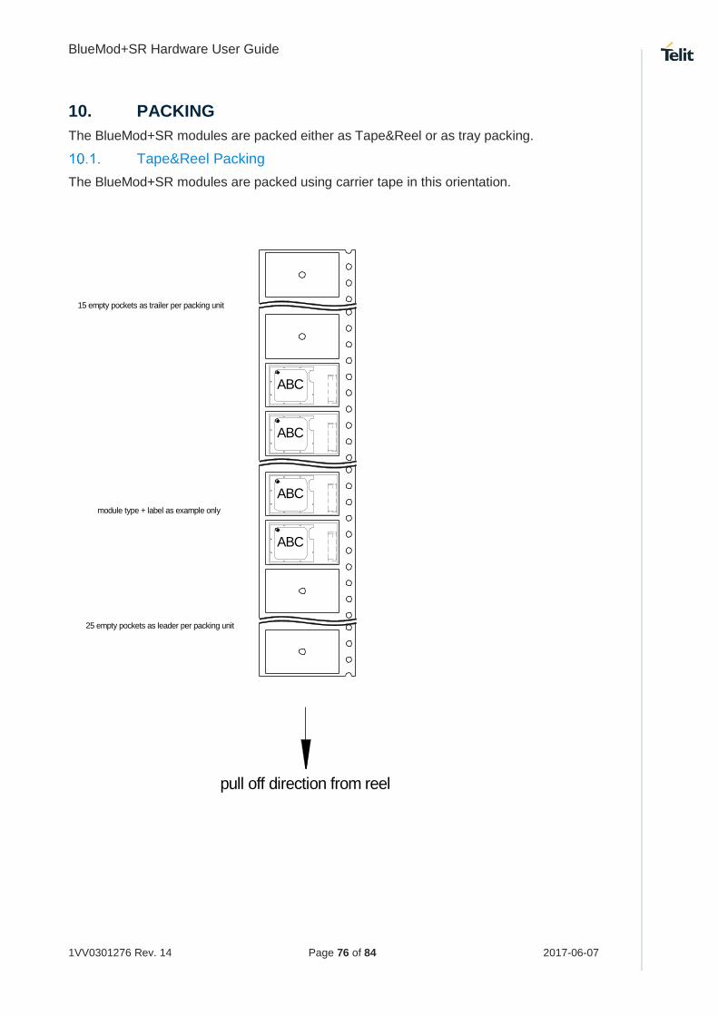
BlueMod+SR Hardware User Guide
1VV0301276 Rev. 14 Page 76 of 84 2017-06-07
10. PACKING
The BlueMod+SR modules are packed either as Tape&Reel or as tray packing.
Tape&Reel Packing
The BlueMod+SR modules are packed using carrier tape in this orientation.
pull off direction from reel
25 empty pockets as leader per packing unit
15 empty pockets as trailer per packing unit
module type + label as example only
ABC
ABC
ABC
ABC

BlueMod+SR Hardware User Guide
1VV0301276 Rev. 14 Page 77 of 84 2017-06-07
10.1.1. Tape
The dimensions of the tape are shown in the drawing below (values in mm):
2,0+0,1
-0,1
10,9+0,1
-0,1
18,3
+0,1
-0,1
R 0,5
1,7
5+0,1
0
-0,1
0
24,0
+0,3
-0,3
10x4,0=40,0+0,2
-0,2
1,5+0,1
-0,012,0
11,5
+0,1
-0,1
0,3
3,0
10.1.2. Reel
name
p/n
firmware
fw p/n
trace
quantity
Designed in Germany, Made in China
XXXXXXXXXXXXXXXXaaaaa-aab/cddddd-ddmwwyyq
FCC ID: RFRMSIC: 4957A-MS
40
label content as example only
330

BlueMod+SR Hardware User Guide
1VV0301276 Rev. 14 Page 78 of 84 2017-06-07
Tray Packing
10.2.1. Module Orientation
10.2.2. Tray Dimension
Moisture Sensitivity Level
Moisture Sensitivity Level (MSL) for BlueMod+SR is 3.
BlueMod+SR Hardware User Guide
1VV0301276 Rev. 14 Page 79 of 84 2017-06-07
11. EVALUATION KIT
The kit BlueEva+SR is available to evaluate functionality and start your firmware
implementation.

BlueMod+SR Hardware User Guide
1VV0301276 Rev. 14 Page 80 of 84 2017-06-07
12. SAFETY RECOMMENDATIONS
READ CAREFULLY
Be sure the use of this product is allowed in the country and in the environment required.
The use of this product may be dangerous and has to be avoided in the following areas:
Where it can interfere with other electronic devices in environments such as
hospitals, airports, aircrafts, etc.
Where there is risk of explosion such as gasoline stations, oil refineries, etc. It is the
responsibility of the user to enforce the country regulation and the specific
environment regulation.
Do not disassemble the product; any mark of tampering will compromise the warranty
validity. We recommend following the instructions of the hardware user guides for correct
wiring of the product. The product has to be supplied with a stabilized voltage source and
the wiring has to be conformed to the security and fire prevention regulations. The product
has to be handled with care, avoiding any contact with the pins because electrostatic
discharges may damage the product itself. Same cautions have to be taken for the SIM,
checking carefully the instruction for its use. Do not insert or remove the SIM when the
product is in power saving mode.
The system integrator is responsible for the functioning of the final product; therefore, care
has to be taken to the external components of the module, as well as any project or
installation issue, because the risk of disturbing the GSM network or external devices or
having impact on the security. Should there be any doubt, please refer to the technical
documentation and the regulations in force. Every module has to be equipped with a proper
antenna with specific characteristics. The antenna has to be installed with care in order to
avoid any interference with other electronic devices and has to guarantee a minimum
distance from the body (20 cm). In case this requirement cannot be satisfied, the system
integrator has to assess the final product against the SAR regulation.
The European Community provides some Directives for the electronic equipment
introduced on the market. All of the relevant information is available on the European
Community website:
http://ec.europa.eu/enterprise/sectors/rtte/documents/
The text of the Directive 99/05 regarding telecommunication equipment is available, while
the applicable Directives (Low Voltage and EMC) are available at:
http://ec.europa.eu/enterprise/sectors/electrical/

BlueMod+SR Hardware User Guide
1VV0301276 Rev. 14 Page 81 of 84 2017-06-07
13. DOCUMENT HISTORY
Revision Date Changes
02 2013-02-04 First issue
03 2013-02-21 Signal naming conventions harmonized
Signals in tables re-sorted
Corrected some typos
Updated dimension drawing (with new antenna)
Added land pattern drawing
Chapter “Restricted Area” renamed into “Placement Recommendation” and replaced text with drawing
Added figure BlueMod+SR Pin Numbering (Top View)
Added current consumption for standby mode
Revised chapter Introduction
04 2013-05-31 Spelling and formatting
Chapter Application Interface, Examples added to several sub chapters
Chapter Power Supply, requirements lowered
Chapter Reset, allowed to use series resistor to connect external low-active reset
Chapter Serial Interface updated, UICP included
Chapter PIO Interface renamed to GPIO Interface
Chapter WLAN Coexistence, minor changes in text
Pin Strapped System Memory Boot Mode Invocation updated
Chapter Serial Wire DEBUG Interface added
Chapter Pin Description, tables updated and corrected, removed signals “/BT-CONNECTED” and “STM32-WAKEUP”
New chapter Handling of Unused Signals added
Chapter Power Consumption and Power Down Modes, Tables updated
Chapter RF Performance, RF parameter updated
Chapter Antenna-Gain and Radiation Pattern updated
Chapter Re-flow Temperature Profile updated
Chapter Application Diagram added
Chapter Approvals/Certifications updated
05 2013-07-05 Chapter Placement Recommendation updated

BlueMod+SR Hardware User Guide
1VV0301276 Rev. 14 Page 82 of 84 2017-06-07
Revision Date Changes
Chapter Classic Bluetooth, some current measurements added
Chapter Ordering Information: MOQ and number of modules per reel changed to 400
Chapter Approvals/Certifications updated
06 2013-09-04 Chapter Power Consumption and Power Down Modes some current measurements added; tables re-formatted
Chapter Power Supply LDO recommendation updated
Chapter Placement Recommendation updated
Chapter Antenna Issues updated
Chapter KCC Certification added (following chapters renumbered)
Chapter Safety Guidelines completed
Chapter Bluetooth Qualification updated
Chapter Serial Wire DEBUG Interface headline changing, emphasize DEBUG in relation to chapter TRACE Interface added
Chapter Pin Description: Debug and trace functionality in signal naming clarified and added a note on necessity of accessing sign TRACE UART TXD in customer’s hardware
Chapter Power Consumption and Power Down Modes removed “close range”
Chapter Package Label updated to version with KCC ID and logo
07 2014-12-19 Chapter WLAN Coexistence Interface implementation info corrected
Chapter NFC Support chapter added
Chapter Standard Packing Unit 1000 pieces tape and reel added
Chapter Recommended Land Pattern hint “TOP VIEW” added
Chapter 3-Wire Serial Interface Note on data loss extended
Chapter Power Consumption and Power Down Modes 2 sub-chapters SPP and BLE Tables revised Added values using sniff (without using UICP)
08 2015-01-28 Chapter Baud Rate Deviation revised
Chapter Power Consumption and Power Down Modes current measurements with UICP active added
09 2015-04-13 Chapter MIC Certification added
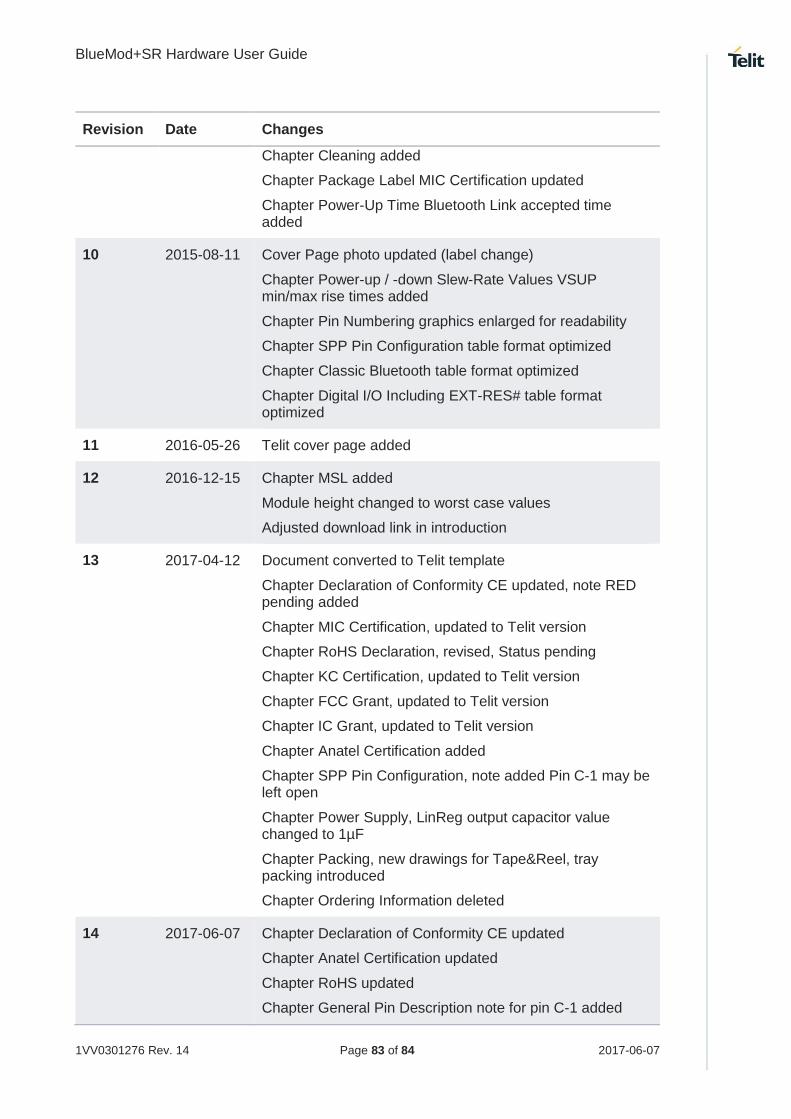
BlueMod+SR Hardware User Guide
1VV0301276 Rev. 14 Page 83 of 84 2017-06-07
Revision Date Changes
Chapter Cleaning added
Chapter Package Label MIC Certification updated
Chapter Power-Up Time Bluetooth Link accepted time added
10 2015-08-11 Cover Page photo updated (label change)
Chapter Power-up / -down Slew-Rate Values VSUP min/max rise times added
Chapter Pin Numbering graphics enlarged for readability
Chapter SPP Pin Configuration table format optimized
Chapter Classic Bluetooth table format optimized
Chapter Digital I/O Including EXT-RES# table format optimized
11 2016-05-26 Telit cover page added
12 2016-12-15 Chapter MSL added
Module height changed to worst case values
Adjusted download link in introduction
13 2017-04-12 Document converted to Telit template
Chapter Declaration of Conformity CE updated, note RED pending added
Chapter MIC Certification, updated to Telit version
Chapter RoHS Declaration, revised, Status pending
Chapter KC Certification, updated to Telit version
Chapter FCC Grant, updated to Telit version
Chapter IC Grant, updated to Telit version
Chapter Anatel Certification added
Chapter SPP Pin Configuration, note added Pin C-1 may be left open
Chapter Power Supply, LinReg output capacitor value changed to 1µF
Chapter Packing, new drawings for Tape&Reel, tray packing introduced
Chapter Ordering Information deleted
14 2017-06-07 Chapter Declaration of Conformity CE updated
Chapter Anatel Certification updated
Chapter RoHS updated
Chapter General Pin Description note for pin C-1 added

[01.2
017]
Mod. 0805 2017-01 Rev.6