blowdown vessels - kotle... · pdf filethe implications of pd 5500 construction include...
TRANSCRIPT
Blowdown vesselsMeeting the requirements
of HSE PM60
2
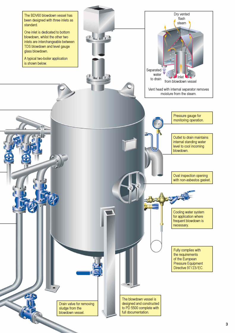
BDV60 blowdown vesselsA complete range of equipment for thesafe disposal of boiler blowdown
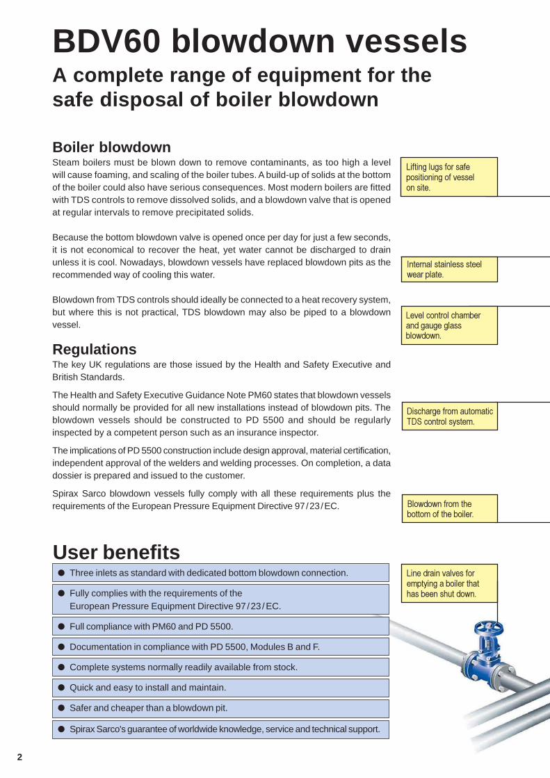
Boiler blowdownSteam boilers must be blown down to remove contaminants, as too high a levelwill cause foaming, and scaling of the boiler tubes. A build-up of solids at the bottomof the boiler could also have serious consequences. Most modern boilers are fittedwith TDS controls to remove dissolved solids, and a blowdown valve that is openedat regular intervals to remove precipitated solids.
Because the bottom blowdown valve is opened once per day for just a few seconds,it is not economical to recover the heat, yet water cannot be discharged to drainunless it is cool. Nowadays, blowdown vessels have replaced blowdown pits as therecommended way of cooling this water.
Blowdown from TDS controls should ideally be connected to a heat recovery system,but where this is not practical, TDS blowdown may also be piped to a blowdownvessel.
RegulationsThe key UK regulations are those issued by the Health and Safety Executive andBritish Standards.
The Health and Safety Executive Guidance Note PM60 states that blowdown vesselsshould normally be provided for all new installations instead of blowdown pits. Theblowdown vessels should be constructed to PD 5500 and should be regularlyinspected by a competent person such as an insurance inspector.
The implications of PD 5500 construction include design approval, material certification,independent approval of the welders and welding processes. On completion, a datadossier is prepared and issued to the customer.
Spirax Sarco blowdown vessels fully comply with all these requirements plus therequirements of the European Pressure Equipment Directive 97/23/EC.
��������������� ���������������������������
��������������������������������������
���� ��������� ��� ��������������������
���������������� ���� ���� ����� ���������
������� ���� ���������������� ���������� �� ��������������
User benefits� Three inlets as standard with dedicated bottom blowdown connection.
� Fully complies with the requirements of theEuropean Pressure Equipment Directive 97 /23/EC.
� Full compliance with PM60 and PD 5500.
� Documentation in compliance with PD 5500, Modules B and F.
� Complete systems normally readily available from stock.
� Quick and easy to install and maintain.
� Safer and cheaper than a blowdown pit.
� Spirax Sarco's guarantee of worldwide knowledge, service and technical support.
������ ��� ����������� ���� ���
3
������� ������������� ���� � ���������������������������� ��
��� � ���� ���
����� �� �����������������������
������������ ��� �
��������� ������������ ����� ������������� ������������������ ���
!������ ��������������������� �����
"� ���������������������������# ������ $���
"���������� ���� ��� �������� ��� ������� ����������������������������������
%���������������������� ��������������&���� �!�����& ����������������'( ) *+ )&��
�������,-���������������� ������������������������������ � �� ���
"���������������� ���������������������.�������������������������� ���������� ��� ������������������������ ���������� ���� ����������
/������ �����#������� ����� �����������������
�� ���� �������������������������������������������
��������������������������� ���������������!��00--������������������������� �����
4
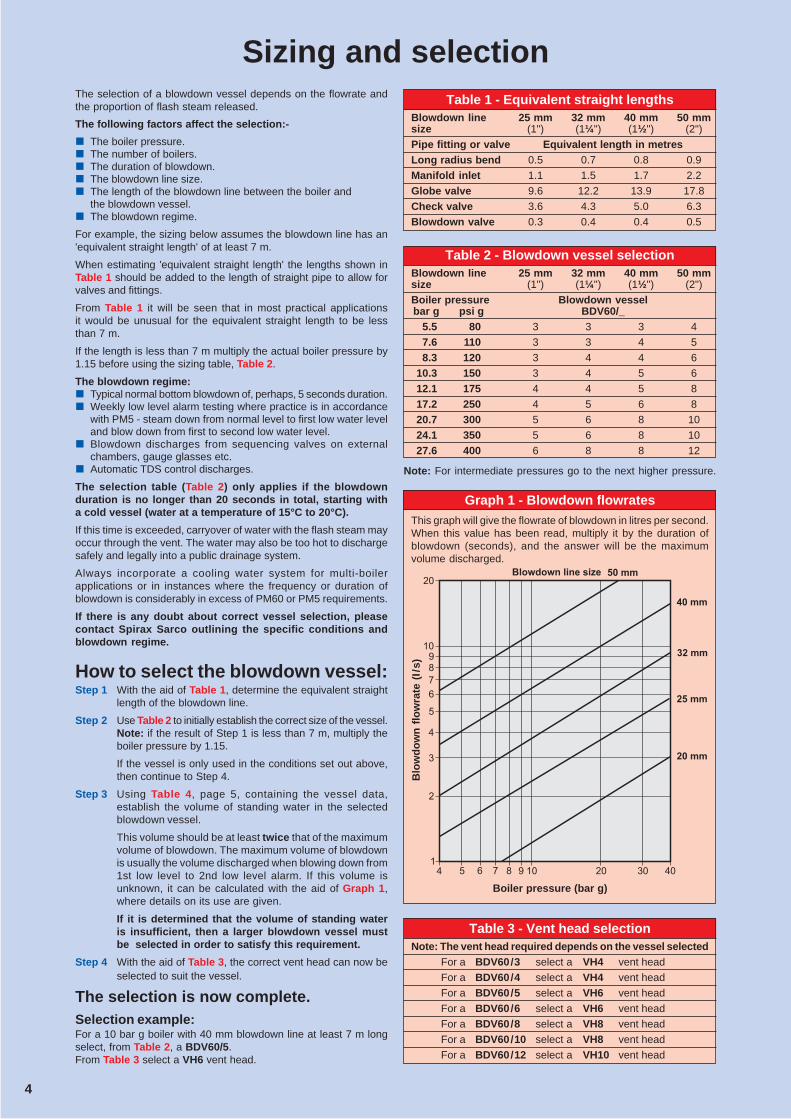
Sizing and selectionThe selection of a blowdown vessel depends on the flowrate andthe proportion of flash steam released.
The following factors affect the selection:-
� The boiler pressure.� The number of boilers.� The duration of blowdown.� The blowdown line size.� The length of the blowdown line between the boiler and
the blowdown vessel.� The blowdown regime.
For example, the sizing below assumes the blowdown line has an'equivalent straight length' of at least 7 m.
When estimating 'equivalent straight length' the lengths shown inTable 1 should be added to the length of straight pipe to allow forvalves and fittings.
From Table 1 it will be seen that in most practical applicationsit would be unusual for the equivalent straight length to be lessthan 7 m.
If the length is less than 7 m multiply the actual boiler pressure by1.15 before using the sizing table, Table 2.
The blowdown regime:� Typical normal bottom blowdown of, perhaps, 5 seconds duration.� Weekly low level alarm testing where practice is in accordance
with PM5 - steam down from normal level to first low water leveland blow down from first to second low water level.
� Blowdown discharges from sequencing valves on externalchambers, gauge glasses etc.
� Automatic TDS control discharges.
The selection table (Table 2) only applies if the blowdownduration is no longer than 20 seconds in total, starting witha cold vessel (water at a temperature of 15°C to 20°C).
If this time is exceeded, carryover of water with the flash steam mayoccur through the vent. The water may also be too hot to dischargesafely and legally into a public drainage system.
Always incorporate a cooling water system for multi-boilerapplications or in instances where the frequency or duration ofblowdown is considerably in excess of PM60 or PM5 requirements.
If there is any doubt about correct vessel selection, pleasecontact Spirax Sarco outlining the specific conditions andblowdown regime.
How to select the blowdown vessel:Step 1 With the aid of Table 1, determine the equivalent straight
length of the blowdown line.
Step 2 Use Table 2 to initially establish the correct size of the vessel.Note: if the result of Step 1 is less than 7 m, multiply theboiler pressure by 1.15.
If the vessel is only used in the conditions set out above,then continue to Step 4.
Step 3 Using Table 4, page 5, containing the vessel data,establish the volume of standing water in the selectedblowdown vessel.
This volume should be at least twice that of the maximumvolume of blowdown. The maximum volume of blowdownis usually the volume discharged when blowing down from1st low level to 2nd low level alarm. If this volume isunknown, it can be calculated with the aid of Graph 1,where details on its use are given.
If it is determined that the volume of standing wateris insufficient, then a larger blowdown vessel mustbe selected in order to satisfy this requirement.
Step 4 With the aid of Table 3, the correct vent head can now beselected to suit the vessel.
The selection is now complete.Selection example:For a 10 bar g boiler with 40 mm blowdown line at least 7 m longselect, from Table 2, a BDV60/5.From Table 3 select a VH6 vent head.
Table 3 - Vent head selectionNote: The vent head required depends on the vessel selected
For a BDV60/3 select a VH4 vent head
For a BDV60/4 select a VH4 vent head
For a BDV60/5 select a VH6 vent head
For a BDV60/6 select a VH6 vent head
For a BDV60/8 select a VH8 vent head
For a BDV60/10 select a VH8 vent head
For a BDV60/12 select a VH10 vent head
�
�
�
�
�
���
�
�
� � � � � � � � �
�����
�����
�����
�����
�����
���� �� ������
Blo
wd
ow
n f
low
rate
(I/
s)
Boiler pressure (bar g)
Table 1 - Equivalent straight lengthsBlowdown line 25 mm 32 mm 40 mm 50 mmsize (1") (1¼") (1½") (2")
Pipe fitting or valve Equivalent length in metresLong radius bend 0.5 0.7 0.8 0.9
Manifold inlet 1.1 1.5 1.7 2.2
Globe valve 9.6 12.2 13.9 17.8
Check valve 3.6 4.3 5.0 6.3
Blowdown valve 0.3 0.4 0.4 0.5
Table 2 - Blowdown vessel selectionBlowdown line 25 mm 32 mm 40 mm 50 mmsize (1") (1¼") (1½") (2")
Boiler pressure Blowdown vesselbar g psi g BDV60/_
5.5 80 3 3 3 4
7.6 110 3 3 4 5
8.3 120 3 4 4 6
10.3 150 3 4 5 6
12.1 175 4 4 5 8
17.2 250 4 5 6 8
20.7 300 5 6 8 10
24.1 350 5 6 8 10
27.6 400 6 8 8 12
Note: For intermediate pressures go to the next higher pressure.
Graph 1 - Blowdown flowratesThis graph will give the flowrate of blowdown in litres per second.When this value has been read, multiply it by the duration ofblowdown (seconds), and the answer will be the maximumvolume discharged.
4
5
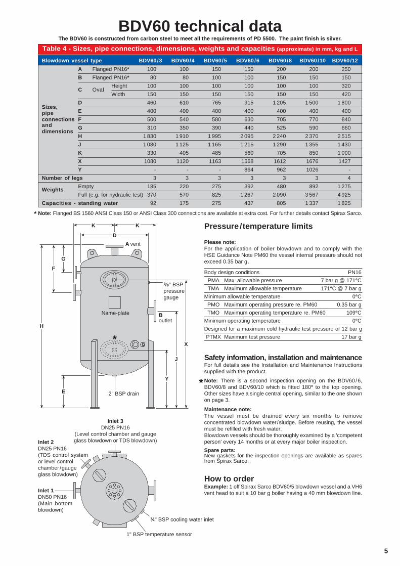
BDV60 technical dataTable 4 - Sizes, pipe connections, dimensions, weights and capacities (approximate) in mm, kg and L
Blowdown vessel type BDV60/3 BDV60/4 BDV60/5 BDV60/6 BDV60/8 BDV60/10 BDV60/12
A Flanged PN16* 100 100 150 150 200 200 250
B Flanged PN16* 80 80 100 100 150 150 150
C OvalHeight 100 100 100 100 100 100 320
Width 150 150 150 150 150 150 420
Sizes,D 460 610 765 915 1 205 1 500 1 800
pipe E 400 400 400 400 400 400 400
connections F 500 540 580 630 705 770 840and G 310 350 390 440 525 590 660dimensions
H 1 830 1 910 1 995 2 095 2 240 2 370 2 515
J 1 080 1 125 1 165 1 215 1 290 1 355 1 430
K 330 405 485 560 705 850 1 000
X 1080 1120 1163 1568 1612 1676 1427
Y - - - 864 962 1026 -
Number of legs 3 3 3 3 3 3 4
WeightsEmpty 185 220 275 392 480 892 1 275
Full (e.g. for hydraulic test) 370 570 825 1 267 2 090 3 567 4 925
Capacities - standing water 92 175 275 437 805 1 337 1 825
Note: Flanged BS 1560 ANSI Class 150 or ANSI Class 300 connections are available at extra cost. For further details contact Spirax Sarco.*
Pressure/temperature limits
Please note:For the application of boiler blowdown and to comply with theHSE Guidance Note PM60 the vessel internal pressure should notexceed 0.35 bar g .
Body design conditions PN16
PMA Max allowable pressure 7 bar g @ 171°C
TMA Maximum allowable temperature 171°C @ 7 bar g
Minimum allowable temperature 0°C
PMO Maximum operating pressure re. PM60 0.35 bar g
TMO Maximum operating temperature re. PM60 109°C
Minimum operating temperature 0°C
Designed for a maximum cold hydraulic test pressure of 12 bar g
PTMX Maximum test pressure 17 bar g
Safety information, installation and maintenanceFor full details see the Installation and Maintenance Instructionssupplied with the product.
Note: There is a second inspection opening on the BDV60/6,BDV60/8 and BDV60/10 which is fitted 180° to the top opening.Other sizes have a single central opening, similar to the one shownon page 3.
Maintenance note:The vessel must be drained every six months to removeconcentrated blowdown water /sludge. Before reusing, the vesselmust be refilled with fresh water.Blowdown vessels should be thoroughly examined by a 'competentperson' every 14 months or at every major boiler inspection.
Spare parts:New gaskets for the inspection openings are available as sparesfrom Spirax Sarco.
How to orderExample: 1 off Spirax Sarco BDV60/5 blowdown vessel and a VH6vent head to suit a 10 bar g boiler having a 40 mm blowdown line.
A vent
2" BSP drain
Boutlet
�" BSPpressuregauge
Inlet 2DN25 PN16(TDS control systemor level controlchamber /gaugeglass blowdown)
Inlet 3DN25 PN16
(Level control chamber and gaugeglass blowdown or TDS blowdown)
Inlet 1DN50 PN16(Main bottomblowdown)
¾" BSP cooling water inlet
1" BSP temperature sensor
The BDV60 is constructed from carbon steel to meet all the requirements of PD 5500. The paint finish is silver.
F
H
G
K K
D
E
J
Y
X
Name-plate
*
*
6
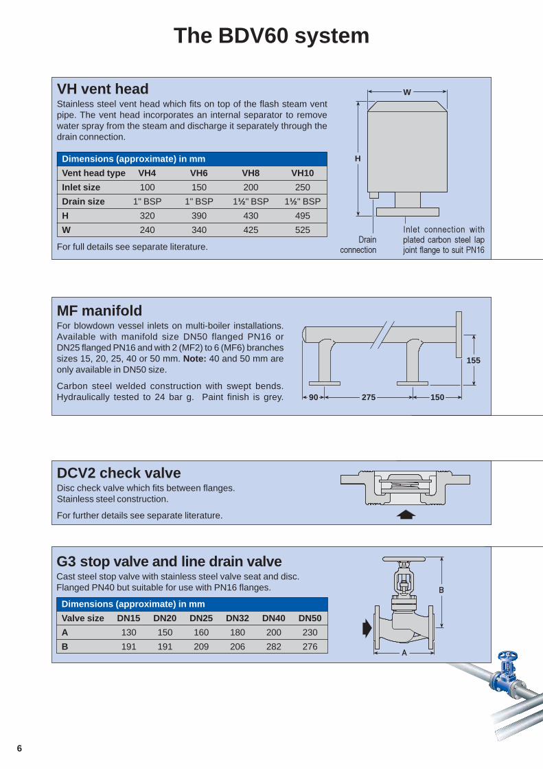
DCV2 check valveDisc check valve which fits between flanges.Stainless steel construction.
For further details see separate literature.
G3 stop valve and line drain valveCast steel stop valve with stainless steel valve seat and disc.Flanged PN40 but suitable for use with PN16 flanges.
Dimensions (approximate) in mm
Valve size DN15 DN20 DN25 DN32 DN40 DN50
A 130 150 160 180 200 230
B 191 191 209 206 282 276
MF manifoldFor blowdown vessel inlets on multi-boiler installations.Available with manifold size DN50 flanged PN16 orDN25 flanged PN16 and with 2 (MF2) to 6 (MF6) branchessizes 15, 20, 25, 40 or 50 mm. Note: 40 and 50 mm areonly available in DN50 size.
Carbon steel welded construction with swept bends.Hydraulically tested to 24 bar g. Paint finish is grey. 90 275 150
155
The BDV60 system
������ ����������� ������ ���� � ����� ����� � �1������� ����������!23,
�� ������������
H
WVH vent headStainless steel vent head which fits on top of the flash steam ventpipe. The vent head incorporates an internal separator to removewater spray from the steam and discharge it separately through thedrain connection.
Dimensions (approximate) in mm
Vent head type VH4 VH6 VH8 VH10
Inlet size 100 150 200 250
Drain size 1" BSP 1" BSP 1½" BSP 1½" BSP
H 320 390 430 495
W 240 340 425 525
For full details see separate literature.
�
�
7
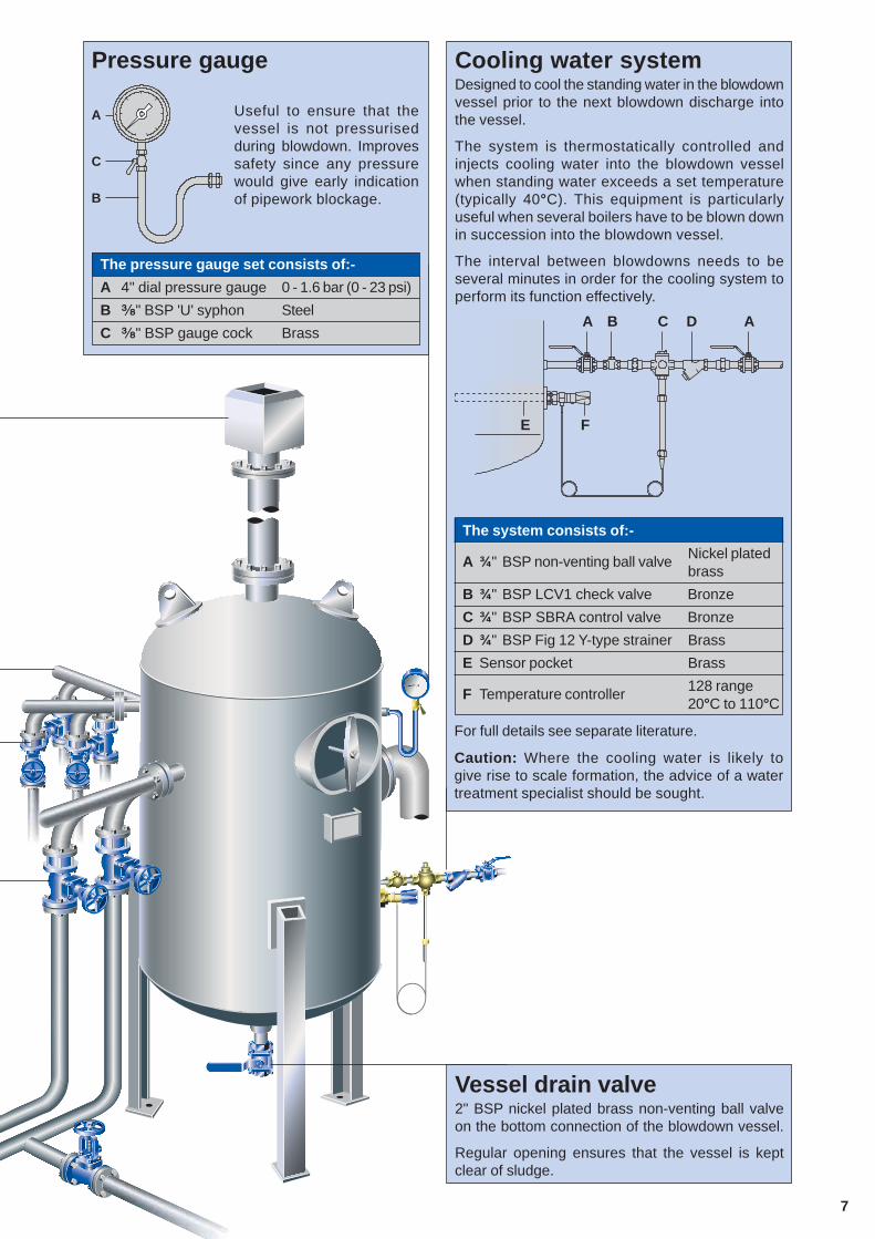
Cooling water systemDesigned to cool the standing water in the blowdownvessel prior to the next blowdown discharge intothe vessel.
The system is thermostatically controlled andinjects cooling water into the blowdown vesselwhen standing water exceeds a set temperature(typically 40°C). This equipment is particularlyuseful when several boilers have to be blown downin succession into the blowdown vessel.
The interval between blowdowns needs to beseveral minutes in order for the cooling system toperform its function effectively.
The system consists of:-
A ¾" BSP non-venting ball valve Nickel platedbrass
B ¾" BSP LCV1 check valve Bronze
C ¾" BSP SBRA control valve Bronze
D ¾" BSP Fig 12 Y-type strainer Brass
E Sensor pocket Brass
F Temperature controller 128 range20°C to 110°C
For full details see separate literature.
Caution: Where the cooling water is likely togive rise to scale formation, the advice of a watertreatment specialist should be sought.
Vessel drain valve2" BSP nickel plated brass non-venting ball valveon the bottom connection of the blowdown vessel.
Regular opening ensures that the vessel is keptclear of sludge.
A
F
B C D
E
A
C
B
Useful to ensure that thevessel is not pressurisedduring blowdown. Improvessafety since any pressurewould give early indicationof pipework blockage.
The pressure gauge set consists of:-
A 4" dial pressure gauge 0 - 1.6 bar (0 - 23 psi)
B �" BSP 'U' syphon Steel
C �" BSP gauge cock Brass
Pressure gauge
A
8
�������������������� ��������� � �� ����������� ���� �$���
Spirax-Sarco Limited, Charlton House,Cheltenham, Gloucestershire, GL53 8ER UK.
Tel: +44 (0)1242 521361 Fax: +44 (0)1242 573342E-mail: [email protected]
Internet: www.SpiraxSarco.com© Copyright 2005 Spirax Sarco is a registered trademark of Spirax-Sarco Limited
SB-P405-01 AB Issue 7
How to specifyA typical specification for the blowdown vessel shown on pages 2 and 3 for a two boiler installation complete withall the ancillaries recommended in PM60 might be as follows:-
Blowdown vessel
1 - Spirax Sarco blowdown vessel type BDV60/5 designed, constructed and tested to PD 55001 - Stainless steel vent head type VH6
For main blowdown from bottom of boiler:
1 - Inlet manifold: type MF2 (DN50), branch sizes DN40 PN162 - Check valves type DCV2, DN402 - Stop valves type G3, DN40 PN16/402 - Line drain valve type G3, DN40 PN16/40
For auto TDS control discharges:
1 - Inlet manifold: type MF2 (DN25), branch sizes DN25 PN162 - Check valves type DCV2, DN252 - Stop valves type G3, DN25 PN16/40
For level controls blowdown:
1 - Inlet manifold: type MF2 (DN25), branch sizes DN15 PN162 - Check valves type DCV2, DN152 - Stop valves type G3, DN15 PN16/40
Other fittings recommended in PM60:
1 - Blowdown vessel drain valve, 2" BSP1 - Blowdown vessel pressure gauge set1 - Cooling water system