blood treatment patent ac
TRANSCRIPT

8/3/2019 Blood Treatment Patent AC
http://slidepdf.com/reader/full/blood-treatment-patent-ac 1/19
United States PatentKaali et ale
[19]
1 1 1 1 1 1 1 1 1 1 1 1 1 1 1 1 1 1 1 1 1 1 1 1 1 1 1 1 1 1 1 1 1 1 1 1 1 1 1 1 1 1 1 1 1 1 1 1 1 1 1 1 1 1 1 1 1 1 1 1 1 1 1 1 1 1 1 1 1 1 1 1 1 1 1
[11]
[45]
USOO5188738A
Patent Number:
Date of Patent:
5,188,738
* Feb. 23, 1993
[54] ALTERNATING CURRENT SUPPLIEDELECTRICALLY CONDUCTIVE METHODAND SYSTEM FOR TREATMENT OFBLOOD AND/OR OTHER BODY FLUIDSAND/OR SYNTHETIC FLUIDS WITHELECTRIC FORCES
[76] Inventors: Steven Kaali , 88Ashford Ave.,Dobbs Ferry, N.Y. 10522;Peter M.Schwolsky, 4101 Cathedral Ave.,NW., Washington, D.C. 20016
The portion of the term of this patentsubsequent to Aug. 18,2009 has beendisclaimed.
["'] Notice:
[21] Appl. No.: 615,437
[22] Filed: Nov. 16, 1990
Related U.S. AppUcationData
[63] Continuation-in-part of Ser. No. 562,721, Aug. 6, 1990,
abandoned.
[51] Int. Cl.s 30m 35/06; A61K 41/00[52] U.S. Cl •............................... . 2101748; 128/419 R;
128/421; 128/783; 128/784; 2041131; 204/164;
204/186; 204/302; 210/243; 422/22; 422/44;604/4
[58] Field of Search 210/243,748, 764;128/419 R, 421, 783, 784; 604/4; 422/22, 44;
204/131,164,186,242,275,302,305
[56] References Cited
U.S. PATENT DOCUMENTS
592,735 10/1897 Jones 204/242
672,231 4/1901 Lacomme 204/275
2,490,730 12/1949 Dubilier 204/305
3,692,648 9/1972 Matloff et aJ. 204/129
3,753,886 8/1973 Myers 204/186
3,878,564 4/1975 Yao et aJ. 210/648
3,965,008 6/1976 Dawson 422/22
3,994,799 11/1976 Yao et al. 210/321.64
4,473,449 9/1984 Michaels et aJ. 204/101
4,616,640 10/1986 KaaJi et aJ. 128/130
4,770,167 9/1988 Kaali et al. 1281788
4,932,421 6/1990 Kaali et al. 128/831
5,049,252 9/1991 Murrell 210/243
5,058,065 10/1991 Slovak 1281783
5,133,932 7/1992 Gunn et al 210/748
FOREIGN PATENT DOCUMENTS
995848 7/1983 U.S.S.R 210/243
OTHER PUBLICATIONS
Proceedings of the Society for Experimental Biology &
Medicine, vol. I, (1979), pp. 204-209, "Inactivation of
Herpes Simples Virus with Methylene Blue, Light andElectricity"-Mitchell R. Swartz et al.Journal of the Clinical Investigation published by theAmerican Society for Clinical Investigations, Inc., vol.65; Feb. 1980, pp. 432-438- "Mechanisms of Photody-namic Inactivation of Herpes Simplex Viruses"-Lowell E. Schnipper et al.
Journal of Clinical Microbiology, vol. 17, No.2, Feb.1983, pp. 374-376, "Photodynamic Inactivation of
Pseudorabier Virus with Methylene Blue Dye, Lightand Electricity"-Janine A. Badyisk et al.
Primary Examiner-Robert A. DawsonAssistant Examiner-Sun Uk KimAttorney, Agent, or Firm-Charles W. Helzer
[57] ABSTRACT
A new alternating current process and system for treat-ment of blood and/or other body fluids and/or syn-
thetic fluids from a donor to a recipient or storage re-ceptacle or in a recycling system using novel electri-cally conductive treatment vessels for treating bloodand/or other body fluids and/or synthetic fluids with-electric field forces of appropriate electric field strength
to provide electric current flow through the blood orother body fluids at a magnitude that is biologicallycompatible but is sufficient to render the bacteria, virus,parasites and/or fungus ineffective to infect or affectnormally healthy cells while maintaining the biologicalusefulness of the blood or other fluids. For this purposelow voltage alternating current electric potentials areapplied to the treatment vessel which are of the order offrom about 0.2 to 12 volts and produce current flowdensities in the blood or other fluids of from one micro-ampere per square millimeter of electrode area exposedto the fluid being treated to about two milliamperes persquare millimeter.
31 Claims, 6 Drawing Sheets

8/3/2019 Blood Treatment Patent AC
http://slidepdf.com/reader/full/blood-treatment-patent-ac 2/19
u.s. Patent Feb. 23, 1993 Sheet 1 of 6 5,188,738

8/3/2019 Blood Treatment Patent AC
http://slidepdf.com/reader/full/blood-treatment-patent-ac 3/19
us, Patent Feb. 23, 1993
33.1 4
rt
- v l J1l_ - = 1 - 1 E ; ;~
~ E : : ~
~ ~
~
~
V :: __ -'--32A 8 : :, , ~~
~
V :: --- ~ [ \ 3 6~
-~
~ -I- ~
~ -1--- ~
~ ~-- ~V :: III ~
•[ ; ; ; --
~[ ; ; ; ---'- ~~ ~~ ~~ - ---l--
~
4~ 32........
~~ -- ~
~
KII ~-;
~+- ~
35 ~ ~r- ~
~- ~
~
I t iiz
~
~ ~
~ ~
'\~ ~
~ b :~ ~r- ... - ... ~[ ; ;
, r-
~
--- -------- .~
~ --32A . r ; ; ;~I~
~..- -•...-
~~ -~
---_--- ~
~ r-~
~
....- .. _ - ---.-._~
~.-II ~-_.~-=I I ~
V :: ~
Sheet 2 of 6 5,188,738
I
+ -
I

8/3/2019 Blood Treatment Patent AC
http://slidepdf.com/reader/full/blood-treatment-patent-ac 4/19
u.s. Patent Feb. 23, 1993 Sheet 3 of 6 5,188,738
I1""444 . 1 II ..\' II a, t1 r~:!•.'1tJ M 71 l}o
1 t \1 1 4 2
, " ' , . 144 II ~4
\\ T .... /, , _ . . . . / /"
,~-------~ ~-------.::.=.---- --- -,_~---- ----.~--
'. . . .
.119-11
5"2L
52!?
:SIL

8/3/2019 Blood Treatment Patent AC
http://slidepdf.com/reader/full/blood-treatment-patent-ac 5/19
u.s. Patent Feb. 23, 1993 Sheet 4 of 6 5,188,738

8/3/2019 Blood Treatment Patent AC
http://slidepdf.com/reader/full/blood-treatment-patent-ac 6/19
u.s. Patent Feb. 23, 1993 Sheet 5 of 6 5,188,738
96
97
15A _ _ J _ _ . _
nf-15 Hf15A
i'i7'-12 10l .
fJj-1BA
IO/~
i
8/3/2019 Blood Treatment Patent AC
http://slidepdf.com/reader/full/blood-treatment-patent-ac 7/19
u.s. Patent Feb. 23, 1993 Sheet 6 of 6 5,188,738
TEf r1PE~1I TURE.
. C Of/T RO LL ED
ENVlROM£NT. . . __
ri9-18
~MPERAroR£r-----~
CONTROLLER t-------oI--"
------------cll== / 1 /
J3 - \. TEMPERIITURE.
<,CONTROLLE.D
£NVIROMENT
FIG. 19 .

8/3/2019 Blood Treatment Patent AC
http://slidepdf.com/reader/full/blood-treatment-patent-ac 8/19
for recirculating a single donor's or patient's blood orother body fluids. The treatment can be accomplishedin a treatment system external of the body or by implantdevices for purging contaminants using a novel electri-
5 caIly conductive vessel for direct electric treatment ofblood or other body fluids, such as amniotic fluids, withalternating current electric field forces of appropriate
electric field strength to attenuate such contaminants tothe extent that bacteria, virus, fungus, and/or parasites
10 contained in the blood or other body fluids are rendered
ineffective to infect and/or affect normalIy healthyhuman ceIls. The treatment, however, does not render
the blood or other body fluids biologically unfit for usein humans or other mammals after the treatment. The
15 new methods and systems according to the inventionachieve these ends without requiring time consumingand expensive processing procedures and equipment in
addition to those normally required in the handling ofblood or other body fluids or synthetic fluids. The in-
20 vention can be used to achieve the electric field force
It is now we1~known in the medical. profession and treatment during the normally occurring transfer pro-the general public that blood collected In a bl~ bank cessing from a donor to a recipient or to a colIectionfrom a ~argenumber of dono~s may be con~Inated by receptacle, or recirculation of a single donor's or pa-contannnants such as bactena, VITUS,parasites and/or tient's blood or other body fluids such as amnioticfungus obtained from even a single donor. While 25 fluids. 'screening of donors has done much to alleviate thisproblem, the screening of donors can and does missoccasional donors whose blood is unfit for use. Whenthis occurs and the unfit blood ismixed with otherwiseusable blood, the entire batch must be discarded for 30transfusion purposes. Because of this problem, the pres-ent invention has been devised to attenuate any bacteria,virus (including the AIDS HIV virus) parasites and/orfungus contained in blood contributed by a donor to thepoint that any such contaminant is rendered ineffective 35
for infecting a normally healthy human cell, but doesnot make the blood biologically unfit for use in humans.Similar problems exist with respect to treatment ofother body fluids, such as amniotic fluids. The treat-ment method and system is also applicable to mammals 40other than humans.In addition to the above, there is a need for methods
and systems for the treatment of blood and other bodyfluids both in in-situ processing wherein the treatedblood and/or other body fluids are withdrawn from the 45
body, treated and then returned to the body in a closedloop, recirculating treatment process that is locatednear but outside the patient's body, or the treatment canbe effected through implanted treatment system compo-
nents.In co-pending United States application serial No.
07/615,800 entitled "Electrically Conductive Methodsand Systems for Treatment of Blood and Other BodyFluids with Electric Forces"-Steven Kaali and Peter M.Schwolsky, inventors, filed concurrently and co-pend- 55ing with this application, a similar treatment methodand system employing direct current excitation poten-tials is described and claimed. The disclosure of co-pending application Ser. No. 07/615,800 hereby is in-corporated into this application in its entirety. 60
15,188,738
ALTERNATING CURRENT SUPPLIEDELECTRICALLY CONDUCTIVE METHOD ANDSYSTEM FOR TREATMENT OF BLOOD AND/OROTHER BODY FLUIDS AND/OR SYNTHETIC
FLUIDS WITH ELECTRIC FORCES
FIELD OF INVENTION
This is a continuation-in-part application of prior U.S.patent application Ser. No. 07/562,721 filed Aug. 6,1990, now abandonedThis invention relates to novel electricaIly conduc-
tive methods and systems employing electrically con-ductive vessels provided with electrically conductivesurfaces for use in SUbjectingblood and/or other bodyfluids and/or synthetic fluids such as tissue culture me-dium to direct treatment by alternating current electricforces.
BACKGROUND PROBLEM
SUMMARY OF INVENTION
The present invention provides new electricalIy con-
ductive methods and systems using alternating electriccurrent excitation potentials for treating blood and/or 65other body fluids, such as amniotic fluids, and/or syn-thetic fluids such as tissue culture medium from a donorto a transfusion recipient or to a storage receptacle, or
2
BRIEF DESCRIPTION OF DRAWINGS
The above and many other objects, features and at-
tendant advantages of this invention will be appreciatedmore readily as the invention becomes better under-stood from a reading of the folIowing detailed descrip-tion, when considered in connection with the accompa-nying drawings, wherein like parts in each of the sev-eral figures are identified by the same reference charac-
ters, and wherein:FIG. 1is a diagrammatic, fragmentary, elevationalview of a new blood transfer system using a novel alter-nating current electricalIy conductive treatment vesselin the form of conductive tubing to directly treat bloodbeing transferred to a storage receptacle with electricfield forces according to the invention;FIG. 2is an enlarged, horizontal cross sectional view
of the novel electrically conductive tubing treatmentvessel taken across lines 2-2 of FIG. 1;FIG. 3is a longitudinal, vertical sectional view of the
novel electrically conductive tubing treatment vesseltaken along the staggered section lines 3-3 of FIG. 2;FIG. 4 is a view similar to FIG. 2 showing a different
50 construction of the novel electrically conductive tubingtreatment vessel;FIG. 5 is a view similar to FIG. 3, taken along the
staggered section lines 5-5 of FIG. 4;FIG. 6 is a diagrammatic, fragmentary, elevational
view showing a different modification of a novel bloodtransfer system using a novel electrically conductivetubing treatment vessel, and which employs a bloodpump and a blood flow regulator;FIG. 7 is an enlarged cross sectional view, similar to
FIG. 2 that shows an electrically conductive tubingtreatment vessel fabricated from longitudinally extend-ing, integrally molded strips of alternate polarity, con-ductive polymer interconnected by integrally molded,
insulating, longitudinally extending strips made of poly-mer or other insulating material;FIG. 8 is a diagrammatic, fragmentary elevational
view showing a different form of a blood transfer sys-tem according to the invention wherein a small electri-

8/3/2019 Blood Treatment Patent AC
http://slidepdf.com/reader/full/blood-treatment-patent-ac 9/19
35,188,738
cally conductive vessel in the form of a short piece oftubing and a miniaturized battery power source areimplanted in the arm of a human being to provide anovel electrically conductive blood and other bodyfluid treatment system which operates in a closed loop, 5
recirculating manner;FIG. 9 is a partial, diagrammatic sectional view of the
upper arm portion of a human being and shows ingreater detail the construction of a specially designedminiaturized, electrically conductive treatment vessel 1 0
with associated miniaturized battery electric powersource and DC to AC power converter for use in theimplant treatment system shown in FIG. 8;FIG. 10 illustrates the details of construction of a
somewhat different form of miniaturized electrified 15
treatment tubing for use in an implanted treatment sys-tem of the type shown in FIG. 8 and built according tothe invention;FIGS. 11and llA illustrate still a different construc-
tion for the electrified treatment tubing for use in prac- 20
tieing the invention wherein the tubing has a square or
rectangular cross section with upper and lower conduc-tive sides and intervening right and left sides separatingthe two conductive sides made from plastic or othersuitable electrical insulating material; 25
FIG. 12 is a perspective top and side view of a novelelectrified, closed, octagonally-shaped, flat, box-liketreatment vessel having an enlarged cross sectional arearelative to the cross sectional diameter of the inlet andoutlet tubes supplying the interior of the treatment ves- 30
sel;FIG. 12A is a partial, cross sectional view of the
enlarged treatment vessel shown in FIG. 12;FIG. 13 is a perspective view of a second form of
enlarged cross sectional area treatment vessel having an 35
exterior shape similar to that of FIG. 12, but whereinthe electrically conductive electrodes of the treatmentvessel comprise interleaved conductive plates with oneset of alternate ones of the plates being electricallyinsulated from the remaining set, and wherein different 40
polarity electric potentials are applied to the respectivesets. If desired, the electrode plates may be formed froman electrically conductive porous material;FIG. 13A is a partial, cross sectional view taken
through the electrically conductive treatment vessel 45
shown in FIG. 13;FIG. 13B isa sectional view taken through staggered
line 13B-13B of FIG. 13A;FIG. 14 is a longitudinal sectional view of still a dif-
ferent form of enlarged diameter electrified treatment S O
vessel wherein the vessel is in the form of an elongatedcylinder, and the sets of conductive electrodes mountedtherein are concentrically arrayed within the interior ofthe treatment vessel and maintained at different electricpotentials; 55
FIG. 14A is a cross sectional view of FIG. 14 takenthrough plane A-A;FIG. 15 is an enlarged longitudinal sectional view of
still another form of an enlarged cross sectional areatreatment vessel according to the invention wherein the 60
electrically conductive electrodes of the treatment ves-sel are comprised by longitudinally extending needle-like electrodes with alternate ones of the needle-like
electrodes being provided with opposite polarity elec-tric potentials; 65
FIG. 15A is a cross sectional view of the treatmentvessel shown in FIG. 15 taken through plane A-A ofFIG. 15;
4FIG. 16A is a partial cross-sectional view taken
through 16A-16A of FIG. 16;FIG. 16 isa perspective view of still another form of
enlarged cross sectional area treatment vessel accordingto the invention wherein the treatment vessel comprisesa relatively large block of insulating material havingparallel, longitudinally extending, open ended tubes
formed through its length. The tubes are provided withelectrically separated, opposed, parallel extending con-ductive plate electrodes which have opposite polarityelectric potentials applied thereto. The ends of the tubesopen into and are supplied from, or supply, respectivereservoirs formed on the respective ends of the centralblock of insulating material containing the tubes, withinlet and outlet conduits for body fluids to be treatedconnected to the free ends of the respective reservoirs;FIG. 17 is a perspective view of an enlarged cross
sectional area treatment vessel similar to FIG. 16wherein the body of the treatment vessel is cylindrical
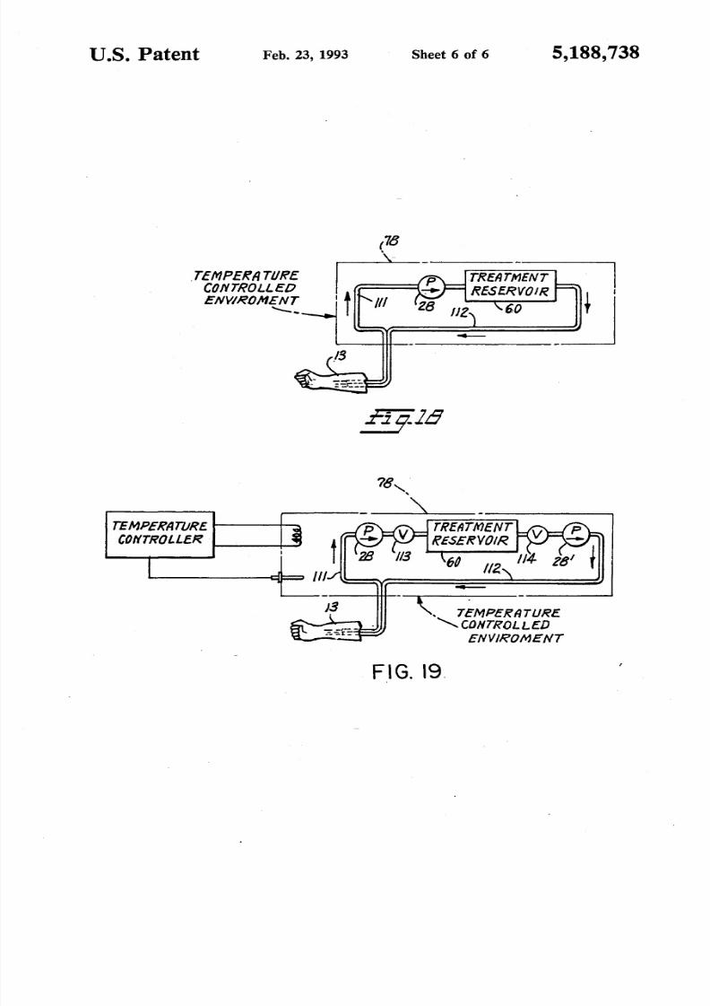
in nature;FIG. 18 is a diagrammatic, fragmentary elevational
view of a human blood or other body fluid treatmentsystem according to the invention employing one of thelarger cross sectional dimension fluid treatment vesselsshown in anyone of FIGS. 12-16 of the drawings, and
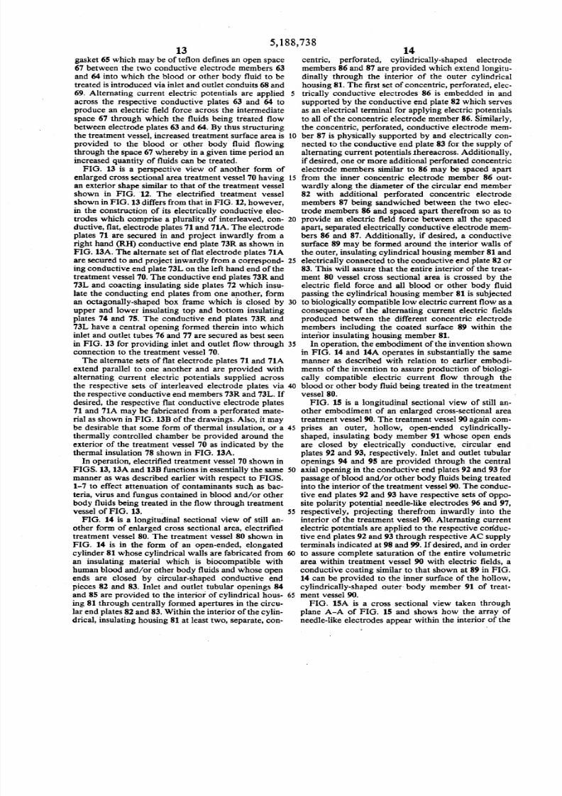
which is suitable for use in a continuous flow throughrecirculating body fluid treatment system; andFIG. 19 is a diagrammatic, fragmentary elevational
view of still another human blood or other body fluid,closed loop, recirculating treatment system accordingto the invention designed for use with the enlargeddiameter fluid treatment vessels illustrated in FIGS.
12-16, and which employs both inlet and outlet fluidpumps on each side of the treatment vessel. With this
arrangement the system can be operated in an intermit-tent manner to allow batch treatment of the body fluidsto fully take place before passage of the body fluidsbeing treated back to the patient.
BEST MODE OF PRACTICING INVENTION
FIG. 1 is a schematic illustration of one form of anovel blood and other body fluid treatment systemaccording to the invention. FIG. 1 shows an electricallyconductive blood and/or other body fluid treatmentvessel constructed according to the invention which isin the form of intravenous tubing 11 interconnectedbetween a hypodermic needle 12 and a blood storagereceptacle 14. The needle 12 is inserted in an artery or
vein of the arm 13 of a blood donor and the tubing 11leads from the arm 13 to the receptacle 14. Alterna-tively, the system could be set up to transfer blood fromthe storage receptacle 14 to the arm of a recipient orcould be designed to recirculate the blood throughelectrified tubing 11back to the donor. The electricallyconductive tubing 11may be of any desired length asindicated by the break at 15 so that it can be appropri-ately set up to lead from a comfortable position for thedonor from whose arm 13 the blood is being taken to aproper storage location for the receptacle 14. Thegreater the length of the electrified portion of tubing 11,then the more extended isthe exposure of the blood (orother body fluid) to the electric field force effects and
low level, biological1y compatible current flow throughthe body fluid being treated thereby assuring adequateelectrification treatment of the fluid without impairingthe biological usefulness of the blood or other bodyfluid being treated.

8/3/2019 Blood Treatment Patent AC
http://slidepdf.com/reader/full/blood-treatment-patent-ac 10/19
55,188,738
FIG. 2 is a cross sectional view of the electricallyconductive tubing 11 taken through plane 2-2 of FIG.1. The tubing 11 may be from 1 to about 20millimetersin inside diameter, although itmay be larger or smallerin diameter depending upon the intended application. 5
For example, if the blood transfer system is for the
purpose shown in FIG. 6, then the tubing may have across sectional dimension of about 5 millimeters. How-ever, if the intended use is in an implanted blood treat-ment system, such as shown in FIG. 8, then the tubing 10diameter must be designed to result in a flow-through
rate corresponding to the natural circulatory bloodflow rate of the patient in which the system is im-planted, and must be long enough to assure effectiveelectrification treatment at the flow rate selected. The 15
tubing 11is formed from plastic, rubber, medical gradepolymer, or other suitable material which is compatible
with human fluids and/or tissue. A plurality of physi-cally separated, electrically conductive surface seg-ments form opposed, parallel electrodes shown at 16 20
and 16A on the inside of tubing 11 from electricallyconductive materials such as platinum, platinum alloys,silver, silver or platinum covered alloys, or other simi-
lar conductive materials such as conductive polymers, 25or silver or platinum covered polymers which are com-patible with human fluids and tissue. The spacing be-tween opposed electrodes 16and 16A is of the order of1 to 19 millimeters and perhaps may be more or less
dependent upon the application and the conductivity of 30the body fluids being treated.FIG. 3 is a longitudinally extending sectional view
along the axis of tubing 11 taken through staggeredsection lines 3-3 of FIG. 2. From FIG. 3 of the draw-
ings it will be seen that the electrically conductive sur- 35
face segments 16 and 16A all comprise longitudinallyextending, zebra-like stripe or strip electrodes whichextend longitudinally in parallel with the longitudinalaxis of the tubing 11. In between each longitudinallyextending conductive stripe electrode 16 or 16A is a 40longitudinally extending electric insulating area 17which electrically isolates the alternate electrically con-ductive, zebra-like stripe electrodes 16 and 16A onefrom the other.As best shown in FIG. 3, a first set of alternate electri- 45
cally conductive surface stripes 16 are electrically con-nected in common to a first annular terminal buss 18which circumferentially surrounds the tubing 11 and isembedded within the sidewalls of the tubing 11 at a
suitable point along its length. The design is such that 50the first annular terminal buss 18 is electrically isolatedfrom the remaining second set of alternate, electricallyconductive surface stripe electrodes 16A and is electri-cally connected through a conductor terminal 19to analternating current source of electric excitation poten- 55tial. AC source 20 may comprise the output from an ACto AC voltage converter for converting 110 volt ACpotential to the desired 0.2 volts to 12 volts for use inthe invention. For those treatment systems which are tobe implanted as described hereafter, the AC source may 60comprise a miniaturized DC to AC converter for con-verting the DC voltage from a miniaturized battery tolow voltage (0.2 to 12 volts) AC. As best depicted in
FIG. 2,all of the first set of positive electrically conduc-tive stripes 16are physically and electrically connected 65in common to the first annular terminal buss 18 so thatall of the conductive stripes 16are maintained at a con-stant, alternating current electric excitation potential.
6A second annular terminal buss 21, which circumfer-
entially surrounds the tubing 11, is embedded within thetubing 11 at a point along its length displaced from theposition of the first annular terminal buss 18 and isspaced inwardly towards the inside diameter of thetubing relative to the first annular buss 18. By this ar-
rangement it is possible to electrically connect the re-maining second set of alternate electrically conductivesurface stripes 16A in common to the second annularterminal buss 21in a manner such that the second annu-lar terminal buss is electrically isolated from the firstannular terminal buss 18as well as the first set of alter-nate electrically conductive surface stripes 16. Asshown in FIG. 3, the second annular terminal buss 21 isprovided with an outside terminal conductor connec-tion 22 for connecting the annular buss 21 and annularbuss 18 across AC source 20 as shown in the systemdrawing of FIG. 1. The second set of alternate electri-cally conductive surface stripes 16A are all providedwith internal connector studs which physically and
electrically connect all of the 16A stripes in common tothe second annular terminal buss 21 so that all of theseconductive stripes will be maintained at a potentialopposite to that from the potential applied to the first setof electrically conductive stripes 16by annular buss 18.As described earlier, the AC source of electric poten-
tial 20 may constitute an AC to AC converter for con-verting 110 volt AC to 0.2 to 12 volt AC or aDC to ACconverter for converting 12 volt DC to 0.2 to 12 voltAC. The AC source 20 is connected to the conductorterminals 19and 22 through electric supply conductors23 and 24 preferably by a double pole, double throw,on-off control switch 25. In preferred embodiments ofthe invention, voltage controlling variable resistors 26and 27 also are included in the electric supply conduc-
tors 23and 24 in order to control the value of the excita-tion voltage developed between the alternate sets ofconductive surface stripes 16, 16A.In operation, the donor whose blood is to be taken, or
the recipient who is to be given blood, or is to have hisor her blood recycled, is made comfortable on a cotwith his or her arm 13extended and the interconnectingelectrically conductive tubing 11 having the hypoder-mic needle 12 for withdrawal, or supplying, or recy-cling of blood set up as shown in FIG. 1.When both thedonor/recipient and the system is in readiness, the con-trol switch 25is closed so that an electric field isbuilt upacross the oppositely disposed electrically conductivezebra-like stripes 16, 16A, etc. Voltages of the order of
from 0.2 to 12 volts are applied to the conductive sur-faces 16, 16A For this purpose it is important to notethat the hypodermic needle should be electrically iso-lated via conventional electrically insulating IV tubingfrom any of the zebra stripe electrodes 16, 16A so thatthe donor/recipient does not receive a shock. By thisprecaution, he or she will not even be aware of theexistence of the electric field within the electricallyconductive tubing 11. With the treatment system thusconditioned, the hypodermic needle is inserted into avein in the donor's/recipient's arm and blood is with-drawn, given, or recycled through the tubing 11.As the blood passes through the electric fields pro-
duced within the electric conductive tubing 11it will be
subjected to and treated 'by biologically compatibleelectric current flow through the blood or other bodyfluid with a current density of from one microampereper square millimeter (1 JLA/mm2) of electrode crosssectional area exposed to the fluid to about two milliam-

8/3/2019 Blood Treatment Patent AC
http://slidepdf.com/reader/full/blood-treatment-patent-ac 11/19

8/3/2019 Blood Treatment Patent AC
http://slidepdf.com/reader/full/blood-treatment-patent-ac 12/19
95,188,738
ity zebra annular stripes being connected to the respec-tive output terminals of AC source 20 via controlswitch 25. If required, a blood pump such as 28 andblood flow regulating valve 37 shown in FIG. 6 can beincluded in the blood transfer system employing electri- 5fied tubing as shown in FIGS. 4 and 5.Similar to the system shown in FIG. 1, a blood trans-
fer system employing the embodiment of the inventionshown in FIGS. 4 and 5 would be electrically excited inadvance of injection of the hypodermic needle 12 into 10the arm of a blood donor so that all blood passingthrough the tubing 11 will be SUbjected to electricforces produced between the alternate polarity annu-lady formed conductive bands 32 and 32A. Experiencewith the invention will establish what length isrequired 15
for the electrification field. However, for initial installa-tions the length of the electrified field as related to theflow of blood through electrified tubing 11 should cor-respond to at least the 1-6 minute treatment time men-tioned earlier. This is achieved by using an extended 20array of the alternate annular zebra bands 32 and 32A ofadequate length to assure thorough subjection of bloodto electric current flow produced between the alternat-ing polarity zebra stripes 32 and 32A. The electric fieldforce intensity applied to the blood by means of the 25electrified tubing is anticipated to be of the order offrom 0. 2 to 12 volts similar to the embodiment of theinvention shown inFIGS. 1-3.In place of supplying continuous alternating current
excitation to the conductive stripes 16, 16A of FIGS. 2 30and 3 or 32, 32A of FIGS. 4 and 5, it also is possible toexcite these electrically conductive segments of tubing11 with pulsed waveform direct current excitation po-tentials. For use in this manner, the pulse rate of thepulsed waveform excitation potentials must be suffi- 35
ciently high to maintain continuous current flowthrough blood being treated. In addition, it may bedesirable to couple a bank of storage capacitors in paral-lel across respective pairs of opposite polarity electri-cally conductive segments 16, 16A and 32, 32A where 40operation in a pulsed DC mode is desired.FIG. 7 of the drawings is a cross sectional view of
another embodiment of the invention which is substan-tially different from those previously described. In FIG.7, the material used for fabrication of the tubing 11 is 45one of the new space-age polymer materials which canbe either highly electrically conductive, insulating, orsemiconducting and may have values of conductivityranging from essentially fully conductive to insulating.
In the embodiment of the invention of FIG. 7, the con- 50ductive surface areas on the inside diameter of the tub-ing 11 are actually formed into segments, such as .nc,of the cross sectional area of the tubing 11 fabricatedfrom the highly conductive polymer material. The in-tervening segments of the tubing 111which separate the 55conductive segments llC are integrally formed fromthe highly insulating polymer material. Suitable positivepolarity and negative polarity potentials are applied tothe exterior surface areas of alternate ones of the sets ofconductive polymer segments llC from a source of 60electric potential via the conductors 23 and 24 as illus-trated schematically in FIG. 7.It will be appreciated that the embodiment of the
invention shown in FIG. 7 is much simpler and henceless expensive to make in that it requires fewer process- 65ing steps than the embodiments of the invention shownin FIGS. 1-6. In other respects, the embodiment of theinvention shown in FIG. 7 would be used in a blood
10transfer system similar to that shown in FIG. lor 6 withor without a blood pump 28 and blood flow regulatingvalve 37 to effect transfer of blood from a donor to areceptacle or recipient in the event of a transfusion orrecycling. During the blood transfer process, again itwould be necessary to provide alternating current exci-tation potentials across the spaced-apart, alternate setsof electrically conductive polymer segments lIC priorto passing blood through the tubing 11. This will assurethat all of the blood being transferred is subjected to theelectric field forces produced between the alternateconductive surfaces lIC. As-a variation of the FIG. 7embodiment, which visualizes that the segments llCand 111 all extend longitudinally and parallel to thelongitudinal axis of tubing 11, it would be possible, butmore elaborate to design, to employ alternate radiallysurrounding annular conductive segments llC and in-terlacing insulating segments 111similar to FIG. 5, butsuch fabrication would require somewhat more com-plex terminal buss bar electric supply connections 23and 24 than those shown in FIG. 7.FIG. 8 is a fragmentary, diagrammatic, elevational
view showing a form of blood treatment system accord-ing to the invention wherein a small electrically con-ductive vessel 41 in the form of a short piece of electri-fied tubing and a combined miniaturized DC to ACconverter and battery power source 42 are implanted inthe arm of a human being. The electrified tubing 41 maybe in the form of any of the prior disclosed electrifiedtubing structures described with relation to FIGS. 1-7,but which are fabricated inminiaturized form so thatthe tubing 41 and power package 42 can be inserted ina section of or surrounding a vein 44 of the arm 13 of apatient whose blood is being treated. The implantationis such that the blood through the patient's vein 44
naturally is pumped through the short piece of electri-fied tubing 41 while circulating blood to the hand of thepatient to thereby form a closed loop, recirculating,implanted treatment system that comprises an integralpart of the circulatory system of the patient beingtreated. Because the parameters of such an implantedsystem are necessarily small, a single passage throughthe implanted electrified tube 14 may accomplish rela-tively little attenuation of contaminants in the blood.Therefore, it is the repeated passage of small portions ofthe patient's blood continuously twenty-four hours aday and for as many days as are needed which willgradually attenuate the contaminants to the point wherethey are rendered ineffective as described earlier.
FIG. 9 is a partial, fragmentary, sectional view of theupper ann portion 13 of a vein or artery of a patient inwhich a treatment system according to the inventionhas been implanted, and shows in greater detail theconstruction of a specialized, miniaturized, electricallyconductive treatment vessel with associated miniatur-ized battery electric power source and DC to AC con-verter for use in an implanted treatment system asshown in FIG. 8. In FIG. 9, the electrified vessel 41 isin the form of an outer housing 45 that isin the shape ofa football which is implanted within the interior walls44 of an artery or a vein. The outer housing 45 is com:prised by a central, cylindrically-shaped portion 45M ofsolid conductor such as platinum which is biocompati-
ble with human blood and tissue and has integrallyformed, conically-shaped porous ends 45C which areattached to and form an electrically conductive screengrid (at the same potential) as the mid portion 45M. Theconical end portions 45C both are perforated and may

8/3/2019 Blood Treatment Patent AC
http://slidepdf.com/reader/full/blood-treatment-patent-ac 13/19
115,188,738
be inthe nature of a screen or mesh wire and of the samematerial composition as the mid portion 45M. Disposedwithin the outer housing 45 isa inner housing 46 whichis tear-drop shaped and secured within the central por-tion 45M of the outer housing by suitable insulating 5support spider legs 47. The inner housing 46 likewise isformed from platinum or other suitable biocompatibleconductive material and has supported within its inte-rior a miniaturized AC source comprising a miniatur-ized battery and AC to DC converter 42 secured to the 10conductive walls of inner housing 46 by conductivesupport legs 48 . The support legs 48 serve as terminalconnectors from one terminal of AC power converter42 to the inner housing 46 so that it is maintained at onepolarity excitation potential. The remaining opposite 15
polarity terminal of miniaturized AC source 42 is con-nected through an insulated conductor 49 to the centralportion 4SM of outer housing 45 whereby the entireouter housing including the meshed conical end por-tions 4SC are maintained at an opposite polarity poten- 20
tial from the inner housing 46.Prior to implantation in a patient, the electrified ves-
sel shown in FIG. 9 is activated by connection to ACsource 42 so that an electric field gradient is producedacross the space between the inner and outer housings 25
45 and 46. Following implantation of the activated,electrified treatment vessel 41, its presence in a vein orartery will cause all blood flowing through the vein orartery to pass between the side walls of the inner andouter housings 45 and 46 so as to be subjected to the 30
electric field force gradient existing in these spaces. Thepresence of the electric field forces will induce a currentflow through the blood passing between the interiorand outer housings as explained above which will resultin attenuating bacteria, virus, parasites and/or fungus 35
which are present in the blood as contaminants. Hereagain, because of the relatively small portion of the totalblood flowing in a patient that will be treated by thedevice within a given time period, it is the repeated,recycling process treatment of the blood over a pro- 40
longed period of time that will result in attenuation ofthe contaminants in the blood to the point where suchcontaminants are rendered ineffective as described ear-lier.In order to further assure adequate treatment of the 45
blood of a patient receiving the implant device, it isrecommended that the blood be treated in an externaltreatment processing facility such as described earlier inFIGS. 1 and 6 or to be described hereinafter with rela-
tion to FIGS. 18 and 19 in which the total capacity of 50the treatment system is greater whereby substantialattenuation effect can be achieved in a comparativelyshorter time period yet to be determined, and then thein vitro implant treatment system such as shown inFIGS. 8, 9 and 10can be used to maintain the attenuated 55condition and to prevent any subsequent build up ofcontaminants after the initial treatment, if determined tobe desirable.FIG. 10 is a fragmentary, diagrammatic view of a
partial vein or artery 44 showing in greater detail the 60
cylindrical or tubular electrified treatment vessel 41originally described with relation to FIG. 8. This im-plant treatment vessel 41 is miniaturized so that it is in
effect an open-ended cylinder in shape and has a diame-ter comparable to that of a large vein or artery and so 65that it can be grafted or implanted into the vein or ar-tery as illustrated in FIG. 10. The tubular treatmentvessel 41 may be designed pursuant to FIGS. 2 and 3 of
12the drawings, for example. For this application, thebattery source of power and interconnected DC to ACconverter 42 are annular in shape and are slipped overthe tubular treatment vessel 41 in the manner shown. InFIG. 10 a longitudinal sectional view of the hollowannular-shaped treatment vessel 41 and AC powersource 42 is illustrated. At the point where the battery
driven AC power source 42 fits over the tubular treat-ment vessel 41, the respective terminals of the ACpower source 42 are exposed to engage the correspond-ing positive and negative supply terminals 19 and 22 ofthe tube 41 so that the resulting structure has a mini-mum exterior profile to facilitate implantation. From acomparison of FIG. 10to FIG. 9 of the drawings, it willbe appreciated that the FIG. 9 treatment vessel intro-duces some flow restriction in the vein or artery inwhich it is implanted and for this reason the construc-tion shown in FIG. 10 is preferred.FIGS. 11 and 11A of the drawings illustrate a con-
struction for the electrified treatment vessel 51whereinthe treatment vessel isin the form of square or rectangu-lar cross sectionally-shaped open-ended tubing. Thetreatment tubing 51provided with a square or rectangu-lar shape so that provision of opposed, parallel conduc-tive electrode surfaces 51U and SlL isgreatly simplifiedas best seen in FIG. llA of the drawings, which is across sectional view taken through plane llA-11A ofFIG. 11.By fabricating the upper and lower surfaces ofthe tubing 11from electrically conductive material suchas platinum, etc., and separating the upper and lowersurfaces 51U and 51L by electrically insulating sidewalls 52R and 52L, provision of the electrically iso-lated, opposed, parallel electrode surfaces is simplifiedand the resulting treatment vessel introduces minimumrestriction to flow of blood. By connecting the uppersurface SIU to one terminal of the AC power source 42and connecting the lower surface 51L to the oppositeterminal, AC electrification of the interior area of thetubing wherein the fluids to be treated flow is readilyachieved with a greatly simplified electrode structure.Variations of this structural feature wherein the sideinsulating surfaces 52R and S2L are curved with theirconcave surfaces facing each other and the cross sec-tional area of the upper and lower conductive surfaces51U and 51L tailored to provide a desired current den-sity, tubular treatment vessels such as shown in FIGS.11 and llA could be readily provided for use inimplan-tation devices such as that illustrated in FIG. 8.FIG. 12 is a perspective view of a novel, electrified,
closed, octagonally-shaped, flat, box-like treatment ves-sel 60 according to the invention which provides anenlarged cross-sectional area relative to the cross sec-tional diameter of the inlet and outlet tubing supplyingthe interior of the treatment vessel whereby increasedthrough-put of a fluid being treated can be achieved ina given time period. The treatment vessel 60 shown inFIG. 12 is comprised essentially of upper and lower,octagonally-shaped, flat insulating plates 61 and 62,respectively, of an insulating material which is compati-ble with human blood and/or other body fluids. Dis-posed immediately below and above the upper andlower plates 61 and 62 are octagonally-shaped, conduc-tive electrode members 63 and 64, respectively, which
are separated and electrically isolated one from theother by a surrounding electric insulating gasket mem-ber 65. The entire structure is sandwiched together andheld in assembled relation by threaded thru-pins 66 asbest seen in FIG. 12A of the drawings. The insulating
8/3/2019 Blood Treatment Patent AC
http://slidepdf.com/reader/full/blood-treatment-patent-ac 14/19
135,188,738
gasket 65 which may be of teflon defines an open space67 between the two conductive electrode members 63and 64 into which the blood or other body fluid to betreated isintroduced via inlet and outlet conduits 68and69. Alternating current electric potentials are applied 5across the respective conductive plates 63 and 64 toproduce an electric field force across the intermediate
space 67 through which the fluids being treated flowbetween electrode plates 63 and 64. By thus structuringthe treatment vessel, increased treatment surface area is 10provided to the blood or other body fluid flowingthrough the space 67 whereby in a given time period anincreased quantity of fluids can be treated.FIG. 13 is a perspective view of another form of
enlarged cross sectional area treatment vessel 70having 15
an exterior shape similar to that of the treatment vesselshown in FIG. 12. The electrified treatment vesselshown in FIG. 13differs from that in FIG. 12,however,in the construction of its electrically conductive elec-trodes which comprise a plurality of interleaved, con- 20ductive, flat, electrode plates 71and 71A. The electrode
plates 71 are secured in and project inwardly from aright hand (RH) conductive end plate 73R as shown inFIG. 13A. The alternate set of flat electrode plates 71Aare secured to and project inwardly from a correspond- 25ing conductive end plate 73L on the left hand end of thetreatment vessel 70. The conductive end plates 73R and73L and coacting insulating side plates 72 which insu-late the conducting end plates from one another, forman octagonally-shaped box frame which is closed by 30upper and lower insulating top and bottom insulatingplates 74 and 75. The conductive end plates 73R and73L have a central opening formed therein into whichinlet and outlet tubes 76 and 77 are secured as best seenin FIG. 13 for providing inlet and outlet flow through 35
connection to the treatment vessel 70.The alternate sets of flat electrode plates 71 and 71Aextend parallel to one another and are provided withalternating current electric potentials supplied acrossthe respective sets of interleaved electrode plates via 40the respective conductive end members 73R and 73L. Ifdesired, the respective flat conductive electrode plates71 and 71A may be fabricated from a perforated mate-rial as shown in FIG. 13B of the drawings. Also, it maybe desirable that some form of thermal insulation, or a 45thermally controlled chamber be provided around theexterior of the treatment vessel 70 as indicated by thethermal insulation 78 shown in FIG. 13A.In operation, electrified treatment vessel 70 shown in
FIGS. 13, 13A and 13Bfunctions in essentially the same 50manner as was described earlier with respect to FIGS.1-7 to effect attenuation of contaminants such as bac-teria, virus and fungus contained in blood and/or otherbody fluids being treated in the flow through treatmentvessel of FIG. 13. 55FIG. 14 is a longitudinal sectional view of still an-
other form of enlarged cross sectional area, electrifiedtreatment vessel 80. The treatment vessel 80 shown inFIG. 14 is in the form of an open-ended, elongatedcylinder 81whose cylindrical walls are fabricated from 60an insulating material which is biocompatible withhuman blood and/or other body fluids and whose openends are closed by circular-shaped conductive endpieces 82 and 83. Inlet and outlet tubular openings 84and 85 are provided to the interior of cylindrical hous- 65ing 81 through centrally formed apertures in the circu-lar end plates 82 and 83.Within the interior of the cylin-drical, insulating housing 81 at least two, separate, con-
14centric, perforated, cylindrically-shaped electrodemembers 86 and 87 are provided which extend longitu-dinally through the interior of the outer cylindricalhousing 81. The first set of concentric, perforated, elec-trically conductive electrodes 86 is embedded in andsupported by the conductive end plate 82 which servesas an electrical terminal for applying electric potentials
to all of the concentric electrode member 86. Similarly,the concentric, perforated, conductive electrode mem-ber 87 is physically supported by and electrically con-nected to the conductive end plate 83 for the supply ofalternating current potentials thereacross. Additionally,if desired, one or more additional perforated concentricelectrode members similar to 86 may be spaced apartfrom the inner concentric electrode member 86 out-wardly along the diameter of the circular end member82 with additional perforated concentric electrodemembers 87 being sandwiched between the two elec-trode members 86 and spaced apart therefrom so as toprovide an electric field force between all the spacedapart, separated electrically conductive electrode mem-
bers 86 and 87. Additionally, if desired, a conductivesurface 89 may be formed around the interior walls ofthe outer, insulating cylindrical housing member 81 andelectrically connected to the conductive end plate 82 or83. This will assure that the entire interior of the treat-ment 80 vessel cross sectional area is crossed by theelectric field force and all blood or other body fluidpassing the cylindrical housing member 81 is subjectedto biologically compatible low electric current flow as aconsequence of the alternating current electric fieldsproduced between the different concentric electrodemembers including the coated surface 89 within theinterior insulating housing member 81.In operation, the embodiment of the invention shown
in FIG. 14 and 14A operates in substantially the samemanner as described with relation to earlier embodi-ments of the invention to assure production of biologi-cally compatible electric current flow through theblood or other body fluid being treated in the treatmentvesse180.FIG. 15 is a longitudinal sectional view of still an-
other embodiment of an enlarged cross-sectional areatreatment vessel 90. The treatment vessel 90 again com-prises an outer, hollow, open-ended cylindrically-shaped, insulating body member 91 whose open endsare closed by electrically conductive, circular endplates 92 and 93, respectively. Inlet and outlet tubularopenings 94 and 95 are provided through the central
axia1opening in the conductive end plates 92 and 93 forpassage of blood and/or other body fluids being treatedinto the interior of the treatment vessel 90. The conduc-tive end plates 92 and 93 have respective sets of oppo-site polarity potential needle-like electrodes 96 and 97,respectively, projecting therefrom inwardly into theinterior of the treatment vessel 90. Alternating currentelectric potentials are applied to the respective conduc-tive end plates 92 and 93 through respective AC supplyterminals indicated at 98 and 99. If desired, and in orderto assure complete 'saturation of the entire volumetricarea within treatment vessel 90 with electric fields, aconductive coating similar to that shown at 89 in FIG.14 can be provided to the inner surface of the hollow,cylindrically-shaped outer body member 91 of treat-ment vessel 90.FIG. 15A is a cross sectional view taken through
plane A-A of FIG. 15 and shows how the array ofneedle-like electrodes appear within the interior of the

8/3/2019 Blood Treatment Patent AC
http://slidepdf.com/reader/full/blood-treatment-patent-ac 15/19
155,188,738
16treatment vessel 90. In operation, the treatment vessel parts including the reservoir headers 103 and 104 and90 will function in substantially the same manner as has would operate in a similar manner.been described previously with relation to earlier de- FIG. 18 is a diagrammatic, sketch of a human bloodscribed embodiments of the invention. or other body fluid treatment system employing one ofFIG. 16 is a perspective view of still another form of 5 the larger cross-sectional dimension fluid treatment
enlarged cross sectional area treatment vessel 100 ac- vessels 60, such as anyone of those shown in FIGS.
cording to the invention and FIG. 16A is a partial cross 12-17 of the drawings. The particular fluid treatmentsectional view taken through plane 16A-16A of FIG. system shown in FIG. 18 is for a continuous flow-16. The treatment vessel 100 comprises a relatively throug~ r~circulating body fluid treatment ~hereinlarge rectangular-shaped block 101 of electrical insulat- 10 bloo~ IS withdrawn from .the arm 13 of a pattent. anding material which is biocompatible with blood and/or supphed through IV tubmg 111 to a commerc~allyother human body fluids. The insulating block 101has a available blood pump 28 and thence to an electn~edplurality of parallel, longitudinally extending, open- treatment vessel 60. The treatment .vessel~ may ~ likeended, tubular-shaped openings 102 formed therein any of the treatment vessel~ descnbed. WIth relation tothrough the entire length of the block. The tubes 102 IS FIGS. 12-17 ?f ~e drawmg~ wherem the blood orare provided with electrically isolated, opposed, paral- other body fluid bemg .treated IS exposed to a low.volt-lei extending conductive plate electrodes 109 as best age, lo~ current ele~tnc curr~nt flow.for attenuatmg t?shown in FIG. 16A, which have alternating current the point ~f re~denng them ineffective, ~y c_ontaml-
. .. f h nants entramed m the blood, such as bactena, V1 l11S andelectnc potentials applied thereacross. One set 0 t ese f Th d blood . t th t t f th
ed f . I b h I I d 20 ungus. e treate appearmg a e ou pu 0 eelectrodes, form or examp e y t e ower e ectro e ttl 60 then i .ul t d b k thr h IV
. ducti trea men vesse en ISrecirc a e ac oug109 ineach tube, extend out to and engage a c~n uct~ve tubing 112 to the arm 13 of the patient whose blood orsurface coatmg formed on one end ~f. the msulatmg other body fluid is being treated. Ifdesired, IV tubingblock, for example 101R, and the :emammg upper elec- 111 and 112 could also be treatment tubing such astrodes 109 form a second set which extend out of ~he 25 described in FIGS. 1-7 and 11. This could provideleft ~and end of the tubes. ~d contact a conductive double treatment for the fluid if that were desirable. Incoatmg ~ormedon the rem~rung end.lOlL of block 101. the event that the entire treatment does not take place inAlternatmg curren~ electnc tx:>tentlalsare connected an air conditioned, temperature controlled room, then itacross the respectIve. con?ucttve sur~aces 101R and may be desirable to provide a temperature controlledlOlL so that a potentl~ ~Ifference e~lsts.between the 30 enclosure indicated by dotted lines 78 around at least=f el~ctrodes 109within each longitudinally extend- the pump 28, electrified treatment vessel 60 and the
~g tube m block .101. The ends of the tube~ 102 open interconnecting IV tubing sections 111and 112in ordermto and are supplied from, or supply, respective header to assure maintaining a substantially constant viscosity
r~ervoirs 103 and 104 ~ormed.on the r~pective oppo- of the blood or body fluid being treated.SIteends of.the block ofmsulatmg matenal 101. Each of 35 Normally, the system of FIG. 18 would be used in a~e reserv01r~~03~d 104h~ a centrally formed .open- continuous flow-through recirculating treatment sys-mg for receiving either an inlet tube lOS applied to tern wherein blood from the patient's arm 13issuppliedheader 103 or an outlet tube 106 sec~red to header 104 through pump 28 to the treatment vessel 60 where it isfor supply of blood or other body fluids to be treated to treated and then discharged back through tubing sec-and from the treatment vessel 100. If desired, a blood 40 tion 112 to the arm of the patient. The flow rate of thepump or other' fluid pump can be inserted between the blood thus processed would be adjusted to correspondsupply tube lOSand header 103, or between outlet tube substantially to the natural flow rate of blood circulated106 and the or outlet from the header reservoir 104, or through the patient's body to the extent possible.both. Alternatively, both inlet and outlet pumps can be In addition to operation in the above manner, itused. In operation, the electrified treatment vessel 100 45 would also be possible to operate the system of FIG. 18shown in FIG. 16 functions in the same manner as those in a stopped-flow, batch treatment manner wherein thespecies of treatment vessels described previously. blood pump is intermittently stopped to allow for moreFor some treatment applications, it may be desirable extended electrical treatment of the blood or other body
to provide exhaust vents such as shown at 107 and 108 fluid contained in the treatment vessel 60 during thein FIG. 16 to the inlet reservoir 103 and/or the outlet S O period of time (referred to as the dwell time) that thereservoir 104 with the vents that can be selectively blood pump is stopped thereby assuring fuller electrifi-operated by valves that can be automatically or manu- cation treatment and the greater attenuation of the bac-ally controlled for venting off gases that might be teria, virus, parasites and/or fungus entrained in thetrapped in the tops of reservoirs and which otherwise blood.
might interfere with the proper operation of the electri- 55 FIG. 19 is a diagrammatic sketch of a form of closedfied treatment vessel. In a similar manner, suitable vent- loop, flow-through recirculating treatment system ac-ing apparatus may be provided to other of the large cording to the invention that is somewhat similar t'o thecross sectional area electrified treatment vessels de- system shown inFIG. 18. FIG. 19 differs from FIG. 18scribed previously. in that an inlet pump 28 and an outlet pump 28' areFIG. 17 isa perspective view of still another enlarged 60 connected to, respectively, the intake to and outlet from
cross-sectional area treatment vessel 110 which is simi- the electrified treatment vessel 60. If desired, an inletlar in all respects to the treatment vessel shown in FIG. control valve 113 and an outlet control valve 114 also16 with the exception that the body or block of insulat- can be interconnected between the inlet pump 28 anding material 101 through which the elongate tubular the intake to the treatment vessel 60 and between theopenings are made, is cylindrically shaped as illustrated 65 output from the treatment vessel 60 and the intake to thein FIG. 17. In other respects, the embodiment of the outlet blood pump 28'. These inlet and outlet controlinvention shown in FIG. 17 would be identical to FIG. valves indicated at 113and 114preferably are automati-16 in the fabrication and operation of its component cally operated in a time sequence which allows the

8/3/2019 Blood Treatment Patent AC
http://slidepdf.com/reader/full/blood-treatment-patent-ac 16/19
175,188,738
system of FIG. 19 to be operated as a two pump, start-stop flow through system. When operated in this man-ner, the first pump 28 is allowed to operate and dis-charge blood from the arm 13 of the patient to bepumped into the treatment vessel 60 and thereafter is 5closed off with both the inlet and outlet valves 113 and114 in their closed condition. At this point electrifica-
tion treatment of the blood or other body fluid takesplace for a predetermined, scheduled time period toassure adequate attenuation to the point of rendering 10
ineffective the contaminant bacteria, virus, parasites orfungus. Upon completion of the pre-scheduled treat-ment period, the outlet valve 114 is opened and outletpump 28' actuated to return the treated blood to the armof the patient 13. Operation in this semi-continuous, 15
start-stop, batch fashion will assure that adequate elec-trified treatment of the blood has been accomplishedwhile achieving this end in a somewhat continuousmanner suitable for use in a closed loop, recycling bloodtreatment process. 20
PRACTICAL USES OF INVENTION
While the disclosure herein presented has been di-rected to principally the electrical treatment of blood, itis believed obvious to those skilled in the art that the 25invention can be applied with corresponding effect toother body fluids which are electrically conductive forthe treatment of contaminants such as bacteria, virus,parasites and/or fungus contained therein. Further,while voltages of the order offrom about 0.2 volts to 12 30volts AC have been indicated as preferable, it ispossiblethat certain virus may be attenuated (or attenuated at afaster rate) if they are subjected to greater electric cur-rent magnitudes of the order of 500 microamperes forshorter time periods. Acceptable current magnitudes 35normally would require an excitation voltage of from0.2 to 12 volts. However, in certain cases where fasteror more complete attenuation of the contaminants inbody fluids may be desired under certain circumstancesand conditions, the excitation voltage supplied to the 40conductive tubing may in fact exceed the 0.2 to 12 voltrange indicated for most treatments.Although it is uncertain what is specifically causing
the attenuation of the contaminants (virus, bacteria,parasites and/or fungus), some possible explanations 45
have been put forward. One is that the attenuation iscaused simply by the direct affect of the electric currentand voltage. Another entails the following. When avoltage is applied to the electrodes, a small current willflow through the electrically conductive medium. The 50applied voltage and ensuing current will induce changesin the complex biologically active fluid. Current canflow through the media if positive and/or negativecharges are transported through said media. The trans-port might induce changes in the charge distribution of 55the biologically active molecules thus changing theirbiological activity. Furthermore, the voltage and cur-rent can induce the production or elimination of differ-ent ions, radicals, gases and/or PH levels which mayaffect, alone or in combination, the biologically active 60
molecules and/or cells. The above products of the elec-trical processes may either be very short lived and stayin the close proximity of the electrodes or can diffuse ormix in the bulk of the media and react with the biologi-
cally active molecules or cells to result in their attenua- 65tion.Having described several embodiments of new and
improved electrically conductive treatment methods
18and vessels for use in practicing the novel method forthe treatment of blood and/or other body fluids withelectric field forces and treatment systems employingthe same, it isbelieved obvious that other modificationsand variations of the invention will be suggested tothose skilled in the art in the light of the above teach-ings. It is therefore to be understood that changes may
be made in the particular embodiments of the inventiondescribed which are within the full intended scope ofthe invention as defined by the appended claims.What is claimed is:1.An electrically conductive vessel for direct electric
treatment of bacteria, and/or virus, and/or parasitesand/or fungus entrained in blood and/or other bodyfluids and/or synthetic fluids contained within or flow-ing through the vessel in the presence of electric field. forces, said electrically conductive vessel being fabri-cated with only biologically compatible material con-tacting the fluid being treated and with an array of atleast two or more spaced-apart, opposed electricallyconductive electrode segments formed of biologically
compatible conductive material on or in the interiorsurface of the vessel and exposed to blood or otherfluids contained in or flowing through the vessel, saidelectrically conductive electrode segments being elec-trically isolated from each other and extending over orthrough a portion of the length of the vessel, and meansfor applying low voltage alternating current non-bio-logically damaging electric potentials to the electricallyconductive electrode segments whereby electrical fieldforces are produced between the electrically conduc-tive electrode segments that induce biologically com-patible current flow through the blood and/or otherfluids contained in or flowing through the vessel so astoattenuate bacteria, virus, parasites and/or fungus con-tained in the blood and/or other fluids by the action ofthe electric current flow therethrough to thereby ren-der the bacteria, virus, parasites and/or fungus ineffec-tive while not impairing and maintaining the biologicalusefulness of the fluids.2. An electrically conductive vessel according to
claim 1 wherein the low voltage alternating currentelectric potentials are in the range from about 0.2 voltsto 12 volts and induce electric current flow densities inthe blood or other fluids of from one microampere persquare millimeter (1 iJ.A/mm2) to about two miIIiam-peres per square millimeter (2 mA/mm2).3. An electrically conductive vessel according to
claim 2 wherein the vessel is in the form of tubing andis inserted in a flow-thru blood treatment system be-tween a hypodermic needle employed to withdrawand/or supply blood from a donor and/or to a recipientand/or a blood storage receptacle or to a patient in ablood recycling system.4. An electrically conductive vessel according to
claim 2 wherein the vessel is part of a system and is inthe form of tubing and a blood pump is inserted itt thetubing between a donor and a recipient or a receptacle,and the system further includes means for electricallyisolating the blood pump from the electrically conduc-tive vessel, means for regulating blood flow rate fromthe blood pump output and means for maintaining elec-trical continuity throughout a desired length of theconductive vessel.
5. An electrically 'conductive vessel according toclaim 2 wherein the vessel is in the form of tubing andthe electrically conductive electrode segments are inthe form zebra stripes which extend longitudinally par-

8/3/2019 Blood Treatment Patent AC
http://slidepdf.com/reader/full/blood-treatment-patent-ac 17/19
19
5,188,73820
allel with the longitudinal axis of the tubing with the 9, Electrically conductive tubing according to claimalternate electrically conductive electrode stripes being 8 wherein the tubing is inserted in a flow-thru bloodseparated by alternate electrically insulating stripes for treatment system between a hypodermic needle em-electrically isolating the alternate electrically conduc- ployed to withdraw and/or. supply blood from a donortive electrode stripes one from the other, a first set of 5 and/or to a recipient and/or a blood storage receptacle
alternate ones of the electrically conductive electrode or to a patient in a blood recycling system,stripes being electrically connected in common to a first 10, Electrically conductive tubing according to claimannular terminal buss formed on and circumferentially 9 wherein a blood pump is inserted in the tubing be-
surrounding the tubing and electrically isolated from tween a donor and a recipient and/or a receptacle, andthe remaining second set of alternate electrically con- 10 the tubing ispart of a system that further includes meansductive electrode stripes, said first annular terminal buss for electrically isolating the blood pump from the elec-being designed for connection to one supply terminal of trically conductive tubing, means for regulating blood
a source of alternating current electric excitation poten- flow ~romt~e output of ~e bloo? pump, and means,fortial and a second annular terminal buss circumferen- electncally mterconnectmg the mput and output sides
t i a l iy surrounding the tubing and electrically connected 15 of the ~bing around the blood ,Pump ~d ~l<><;>dl~wto the remaining second set of alternate electrically re~ulatmg means wh~reby electncal con~ulty IS main-
conductive electrode stripes, said second annular termi- tamed through ~ desired lengt~ of the tubing. ,nal buss being electrically isolated from the first annular ~1, An elec:tncally conductive ves~l accordmg toterminal buss and the first set of alternate electrically claim 2 wh~rem the walls?f the vessel Itself ~e forme~
d ti I t od tri d be' desi d f 20 from electncally conductive polymer matenal that IScon uc, ve e ec res npes an ,mg esigne or compatible with human tissue and blood and/or other
connection to a second supply termmal of a source of bod fl id ith th It' all d ti rti s, I'" ia l Y Ul s WI e e ec nc y con uc ive po Ionalternating ,current e ect~c excI~tlon pote~tl, , being formed into desired patterns of spaced apart elec-6, EI~tncally C?nd~ct~ve tubm~ according to claun trically conductive electrode segments physically inter-
S wherem the tubmg ISmserted ina fl<?w-thrublood 25 connected by integrally formed electrically insulatingtreatment s~stem between a hypodermic needle em- tubing walls portions which electrically isolate a firstployed to W1th~r~wand/or supply blood from a donor array of electrode segments from a second array ofand/or to ~ rec~plent and/or a bl,ood storage receptacle electrode segments,
or to a patl~nt m a blood, recycl~ng system" , 12, An electrically conductive vessel according to7. Ele7 tncally conductl,:,e ~ubmg a~cordmg t~ claim 30 claim 11wherein the vessel is in the form of tubing and
5 wherem a blood pump _Isinserted m the tubing be- the electrically conductive electrode segments are intween ~ do?or and a recipient and/?r a recept8:cle, and the form of zebra stripes which extend longitudinallythe tubmg ISa ~art o~a sy~tem which further includes parallel with the longitudinal axis of the tubing with themean~for electncall~ Isolat~g the blood pump from ~he alternate electrically conductive electrode stripes beingelectncally conductive tubing, means for regulating 35 separated by alternate electrically insulating stripes for
blood flo~ rate f:om the bloo~ pump <?utput,and means electrically isolating the alternate electrically conduc-f?r electncally ~terconnectmg the mput and output tive electrode stripes one from the other, a first set ofSides of the tubmg around the blood pump and the alternate ones of the electrically conductive electrodebl~od ,flow,reg~lating means wherebr electrical conti- stripes being electrically connected in common to a firstnutty IS maintained throughout a desired length of the 40 annular terminal buss formed on and circumferentially
tubing.. .. , surrounding the tubing and electrically isolated from8. An electncally conductive tubing according to the remaining second set of alternate electrically con-
claim 2 wherein the vessel is in the form of tubing and ductive electrode stripes, said first annular terminal bussthe electrically conductive electrode segments are in being designed for connection to one supply terminal ofthe form of zebra stripes which extend radially around 45 a source of alternating current electric excitation poten-the inside diameter of the tubing in alternating conduc- tial, and a second annular terminal buss circumferen-tive and insulating annular bands whereby alternate tially surrounding the tubing and electrically connectedconductive bands are electrically isolated one from the to the remaining second set of alternate electricallyother by respective insulating bands, a first set of alter- conductive electrode stripes, said second annular termi-
nate ones of the electrically conductive annular elec- 50 nal buss being electrically isolated from the first annulartrode stripes being electrically connected in common to terminal buss and the first set of alternate electricallya first longitudinally extending terminal buss that is conductive electrode. stripes and being designed forformed on the tubing in parallel with the longitudinal connection to a second supply terminal of a source ofaxis thereof and electrically isolated from the remaining alternating current electric excitation potential.second set of alternate electrically conductive annular 55 13.Electrically conductive tubing according to claimelectrode stripes, said first longitudinally ext ending 12 wherein the tubing is inserted in a flow-thru bloodterminal buss being designed for connection to a first treatment system between a hypodermic needle' em-supply terminal of a source of alternating current elec- ployed to withdraw and/or supply blood from a donortric excitation potential, and a secondJongitudinally and/or to a recipient and/or a blood storage receptacleextending terminal buss electrically connected to the 60 or to a patient in a blood recycling system.remaining second set of alternate electrically conduc- 14.Electrically conductive tubing according to claimtive annular electrode stripes, said second longitudi- 13 wherein a blood pump is inserted in the tubing be-nally extending terminal buss being electrically isolated tween a donor and a recipient and/or a receptacle, and
from the first longitudinally extending terminal buss and the tubing is part ofa system which further includesthe first set of alternate electrically conductive annular 65 means for electrically isolating the blood pump from theelectrode stripes and being designed for connection to a electrically conductive tubing, means for regulatingsecond supply terminal of a source of alternating cur- blood flow from the output of the blood pump, andrent electric excitation potential. means for electrically interconnecting. the input and

8/3/2019 Blood Treatment Patent AC
http://slidepdf.com/reader/full/blood-treatment-patent-ac 18/19
215,188,738
22output sides of the tubing around the blood pump and 20. A fluid treatment process according to claim 18blood flow regulating means whereby electrical conti- wherein the low voltage alternating current electricnuity is maintained throughout a desired length of the potentials are in the range from about 0.2 to 12 volts andtubing. induce electric current .flow densities in the blood or15. An electrically conductive vessel according to 5 other fluids of from one microampere per square milli-
claim 11wherein the vessel is in the form of tubing and meter (1 iJ.A/mm2) to about two milliamperes perthe electrically conductive electrode segments are in square millimeter (2 mA/mm2).
the form of zebra stripes which extend radially around 21. The product of the process according to claim 20.the inside diameter of the tubing in alternating conduc- 22. A fluid treatment system for attentuating bacteria,tive and insulating annular bands whereby alternate 10 and/or virus, and/or parasites, and/or fungus existing inconductive bands are electrically isolated one from the blood and/or otherbody fluids and/or synthetic fluidsother by respective insulating bands, a first set of alter- being treated without biological damage to the blood ornate ones of the electrically conductive annular elec- other fluids comprising an electrically conductive ves-trode stripes being electrically connected in common to sel formed at least in part of biologically compatiblea first longitudinally extending terminal buss that is 15 conductive material for contacting blood or other fluidsformed on the tubing in parallel with the -longitudinal to be treated, means for subjecting the blood or otheraxis thereof and electrically isolated from the remaining fluids within the conductive vessel to low voltage, lowsecond set of alternate electrically conductive annular alternating current electric field forces for producingelectrode stripes, said first longitudinally extending biologically compatible current flow through the bloodterminal buss being designed for connection to a first 20 or other fluids for a predetermined period of time suffi-
cient to attenuate bacteria and/or virus, and/or para-supply terminal of a source of alternating current elec-
~~e:~::~:m:~e~:, e~~t~c:~~~n~~~fe~~~~~~ a ~ !!=?;~e~TaS~o:=:~~~~~Eiremaining second set of alternate electrically conduc- 25 or other fluids.
tive annular electrode stripes, said second longitudi- 23. A fluid treatment system according to claim 22nally extending terminal buss being electrically isolated wherein the low voltage alternating current electricfrom the first longitudinally extending terminal buss and potentials are in the range from about 0.2 to 12 volts andthe first set of alternate electrically conductive annular produce electric current flow densities in the blood orelectrode stripes and being designed for connection to a 30 other body fluids of from one microampere per squaresecond supply terminal of a source of alternating cur- millimeter (1 iJ.A/mm2) to about two milliamperes perrent electric excitation potential. square millimeter (2 A/mm2).16. Electrically conductive tubing according to claim 24. A fluid treatment system according to claim 22
15 wherein the tubing is inserted in a flow-thru blood wherein the system comprises a plurality of componentstreatment system between a hypodermic needle em- 35 including an electric power source all of which theployed to withdraw and/or supply blood from a donor miniaturized and implanted in the body of a patientand/or to a recipient and/or a blood storage receptacle being treated to fonn a closed loop, continuous recircu-or a patient in a blood recycling system. lating body fluid treatment system.17.Electrically conductive tubing according to claim 25. A fluid treatment system according to claim 22
16 wherein a blood pump is inserted in the tubing be- 40 wherein the conductive vessel is in the form of an opentween a donor and a recipient and/or a receptacle, and ended tube to allow flow-thru treatment of blood andthe tubing is part of a system that further includes means other fluids and is miniaturized along with an electricfor electrically isolating the blood pump from the elec- power source for supply of alternating current electrictrically conductive tubing, means for regulating blood potentials thereto whereby the system may be im-flow from the output of the blood pump, and means for 45 planted in human beings and other mammals to operateelectrically interconnecting the input and output sides as a continuous recirculating fluid treatment process.of the tubing around the blood pump and the blood flow 26. A fluid treatment system according to claim 22regulating means whereby electrical continuity is main- wherein the conductive vessel in the vicinity of thetained throughout a desired length of the tubing. spaced-apart opposed electrically conductive electrode18. A fluid treatment process for attentuating bac- 50 segments is provided with an enlarged cross sectional
teria, and/or virus, and/or parasites, and/or fungus, area wherein enlarged electrically conductive electrodeexisting in blood and/or other body fluids and/or syn- segment surface areas are provided to act on the bloodthetic fluids within a treatment vessel having only bio- or other fluids flowing through the vessel thereby in-logically compatible internal and conductive electrode creasing the through-put and/or effectiveness of thesurfaces therein contacting fluid being treated thereby 55 treatment accomplished within the vessel for a givenmaintaining the biological usefulness of the blood or dwell time.other fluids being treated comprising subjecting the 27. A body fluid treatment system according. to claimfluid within the treatment vessel to low voltage, low 26 wherein the electrically conductive vessel comprisesalternating current electric field forces within non-bio- an enlarged rectangular-shaped body of electrical insu-logically damaging electric field forces for producing a 60 lating material having a plurality of parallel, longitudi-biologically compatible current flow through the blood nally extending tubular openings formed all the wayor other fluids for a predetermined period of time suffi- through the insulating material from one end to thecient to attenuate bacteria and/or virus, and/or para- other and having spaced-apart electrically conductivesites and/or fungus contained in the blood or other metal strips secured to respective opposite sides of all of
fluids to thereby render them ineffective while main- 65 the tubes in opposed, parallel relationship, one set oftaining the biological usefulness of the fluids being corresponding conductive strips of all of the tubes ex-treated. tending out of the ends of each tube on one side or end19. The product of the process according to claim 18. of the body of electrical insulating material and contact-

8/3/2019 Blood Treatment Patent AC
http://slidepdf.com/reader/full/blood-treatment-patent-ac 19/19
235,188,738
ing a conductive surface forming a terminal buss for alI
conductive strips of the set, and the remaining set of
conductive strips projecting out of the opposite ends of
the respective tubes on the opposite end of the insulat-5
ing block to engage a conductive terminal surface, and
header reservoirs formed on each of the ends of the
body of electrical insulating material into which theends of the tubular openings are connected, each header
having a respective inlet or outlet opening for supply of 10
blood and/or other fluids for treatment thereto.
28. A fluid treatment system according to claim 27
wherein the enlarged insulating clock member is cylin-
drically shaped and the header reservoirs at each end of
the block member are correspondingly cylindrically 15
shaped.
29. A fluid treatment system according to claim 2 7wherein selectively operated gas vents are provided in
the top of the respective header reservoirs of the electri- 20
cally conductive vessel.
2430. A fluid treatment system according to claim 26
wherein the electricalIy conductive vessel isin the fonnof an enlarged cross sectional area treatment vessel ofsubstantially greater cross sectional area than the inletand outlet conduits supplying body fluids to be treatedto the vessel and wherein the enlarged cross sectionalarea vessel is included in a blood transfer system be-
tween a hypodermic needle employed to withdrawand/or supply blood from a donor and/or to a recipientand/or a blood storage receptacle or to a patient in acontinuous flow-thru blood recycling system.31. A fluid treatment system according to claim 30
wherein a blood pump is inserted in the flow path of theblood or other fluid either to or from the enlarged crosssectional area vessel, or both, and are located in a tubingsystem between the donor and recipient or receptacle,and the system further includes means for regulatingblood flow rate from or to the enlarged cross sectionalarea treatment vessel via the inlet or outlet pumps orboth.
• • • • •
2 5
30
3 5
40
45
50
5 5
60
65