blocking morphology, with an example from the tigge forecasts lon lat Ф on pv2 giacomo masato b. j....
Post on 21-Dec-2015
218 views
TRANSCRIPT

Blocking morphology, with an example from the TIGGE forecasts
lon
lat
Ф on PV2
Giacomo MasatoB. J. HoskinsT. J. Woollings
NCAS Blocking Workshop, Reading, 15*12*2010

The ‘Wave-breaking’ Approach. Blocking, Direction of Breaking and Relative Intensity Indices.
A case-study. European event and the usage of TIGGE data-set.
TIGGE data-set (THORPEX project).• Oct 2006-present.• 15 days EPS forecast.• 1 control + n perturbed runs.• 10 different centres (not all have theta on PV2).
Results and Conclusions.Methodology applied to the ECMWF and NCEP centres.
Outline

Blocking Index• First calculated by Pelly and Hoskins (2003).• Developed in a 2-dimensional form (lon,lat) by Berrisford et al. (2007).

Warm-Anticyclonic Cold-Cyclonic
lon
n
s
* *
11 iii 11 iii
11 iiDB
*iiRI
2/sinii
2/sinii
Direction of Breaking
Relative Intensity

10 Dec 11 Dec 12 Dec 13 Dec
14 Dec 15 Dec 16 Dec 17 Dec
18 Dec 19 Dec 20 Dec 21 Dec
22 Dec 23 Dec 24 Dec 25 Dec
26 Dec 27 Dec 28 Dec 29 Dec
30 Dec 31 Dec 01 Jan 02 Jan
The event
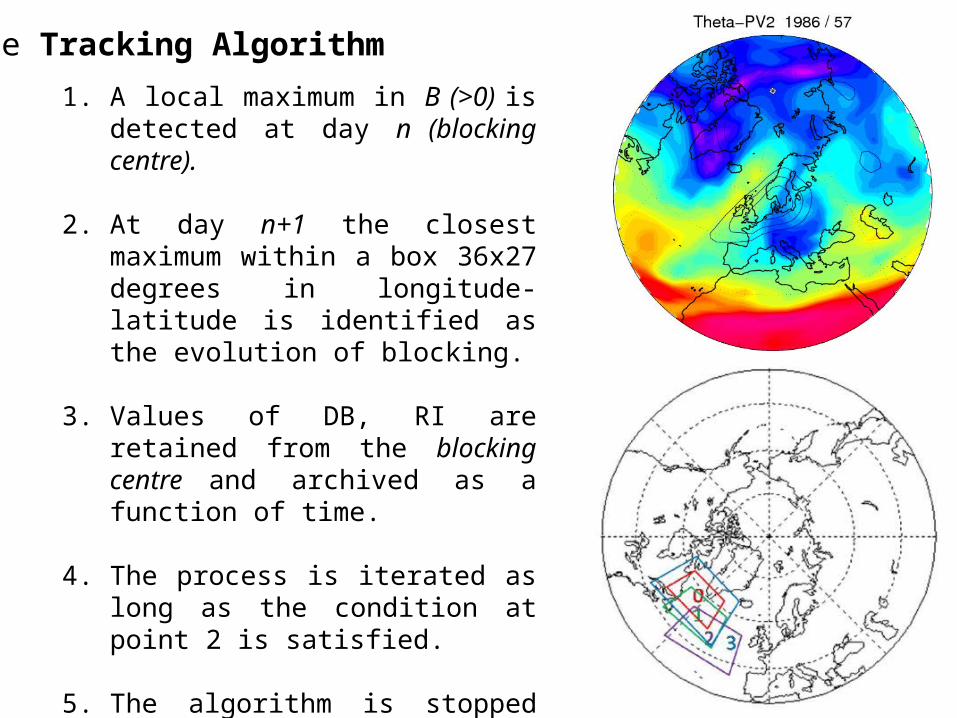
The Tracking Algorithm
1. A local maximum in B (>0) is detected at day n (blocking centre).
2. At day n+1 the closest maximum within a box 36x27 degrees in longitude-latitude is identified as the evolution of blocking.
3. Values of DB, RI are retained from the blocking centre and archived as a function of time.
4. The process is iterated as long as the condition at point 2 is satisfied.
5. The algorithm is stopped if the location of ANY blocking centre is outside a box 3/2 times the box at point 2 and centred on the onset blocking centre.

Days Days
ECMWF NCEP
1st 2nd 3rd
wave-breaking wave-breaking wave-breaking

T
t
I
i
tti
TI
Xx
d1
1
, )(
T
t
I
i
ttitti
TI
YyXx
d1
1
2,
2, )()(
(x,y) = (DB,RI), (EPS members)(X,Y) = (DB,RI), (analysis)
x = B, (EPS members)X = B, (analysis)I = number of memebersT = number of days
Days
ECMWF NCEP
1st 2nd 3rd
wave-breaking wave-breaking wave-breaking
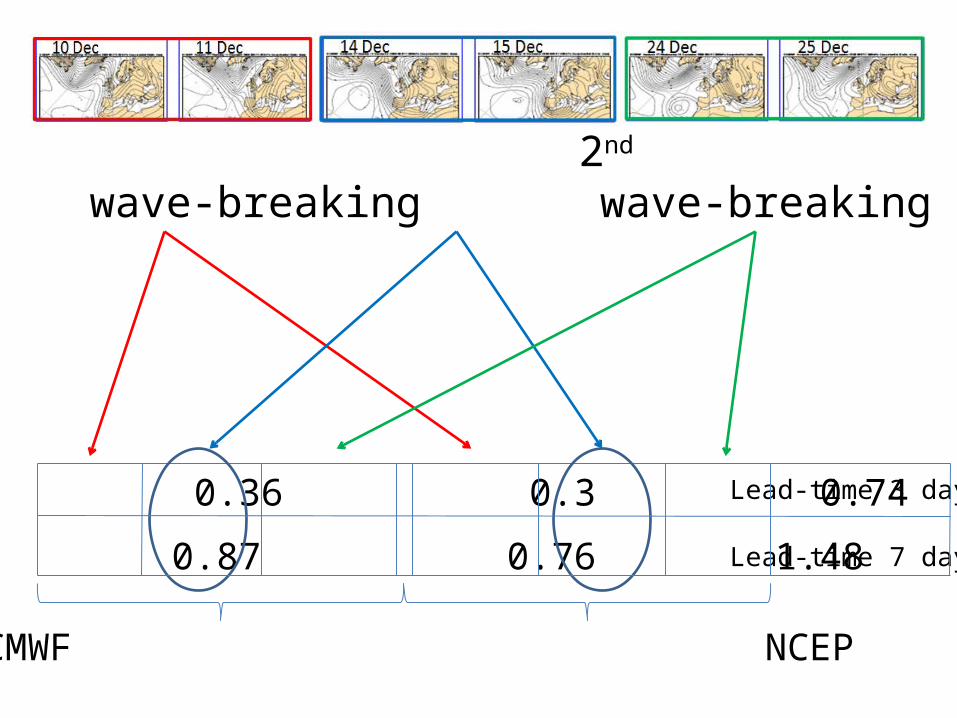
0.71 0.8 0.36 0.3 0.74 0.29
1.17 1.32 0.87 0.76 1.48 0.6
Lead-time 3 days
Lead-time 7 days

Lead-time3 days
(d=0.71)
Lead-time7 days
(d=1.17)
θ B
θ B
θ B θ B
θ B
θ B
ECMWF, WB #1

Lead-time3 days(d=0.8)
Lead-time7 days
(d=1.32)
θ B
θ B
θ B θ B
θ B
θ B
ECMWF, WB #2

Lead-time3 days
(d=0.36)
Lead-time7 days
(d=0.87)
θ B
θ B
θ B θ B
θ B
θ B
ECMWF, WB #3

Lead-time3 days(d=0.3)
Lead-time7 days
(d=0.76)
θ B
θ B
θ B θ B
θ B
θ B
NCEP, WB #1

Lead-time3 days
(d=0.74)
Lead-time7 days
(d=1.48)
θ B
θ B
θ B θ B
θ B
θ B
NCEP, WB #2

Lead-time3 days
(d=0.29)
Lead-time7 days(d=0.6)
NCEP, WB #3 θ B
θ B
θ B θ B
θ B
θ B

A case study has been performed and the wave-breaking approach has been applied to 2 NWP, EPS forecasts.
Three wave-breakings have been identified by the TA. The identification of the second episode (days 14, 15 and 16) was by far the most problematic and both the centres had equally wide spread of ensemble.
It can be inferred that the evolution of the second wave-breaking might have been heavily affected by the decaying phase of the previous one, which has been identified as a clear source of uncertainty for the model.
The relatively smaller wave amplitude characterising the breaking might have also contributed to the poor model performance for its correct identification.
The third wave-breaking (days 24, 25 and 26) exhibits a rather large spread of the ensemble members (first of all for greater lead-time runs), but this does not prevent the forecast capturing correctly the wave-breaking.
Conclusions