blended bat algorithm for optimum design of cantilever
TRANSCRIPT

Blended Bat Algorithm for Optimum Design of Cantilever
Retaining Wall
G S Bath1, J S Dhillon
2 and B. S. Walia
3
1 Corresponding Author, Department of Civil Engineering, Giani Zail Singh Campus College of Engineering and
Technology, MRSPTU, Bathinda-151001, INDIA. [email protected], ORCID 0000-0002-3807-9274 2Department of Electrical and Instrumentation Engineering, Sant Longowal Institute of Engineering and
Technology, Longowal-148106, INDIA 3Department of Civil Engineering, Maharishi Markandeshwar Engineering College Mullana (Ambala) – 133207,
INDIA
Abstract: Cantilever retaining wall is used for the construction of civil engineering projects. Safe and
economical design is the main requirement of the of construction industry. Limit state method of design uses trial
and error method for dimensioning of retaining wall. This procedure is time consuming and may not provide the
optimum dimensions of the cantilever retaining wall. In this paper, blended bat algorithm (BBA) method is
proposed to design the cantilever retaining wall. The stability, geometry and capacity aspects of cantilever
retaining wall are considered for the design of retaining wall. The bat algorithm exploits echolocation searching
behavior of the bats. The bat algorithm is known as a frequency based algorithm. To make a synergic
arrangement of exploration and exploitation abilities, local search procedure is blended with bat algorithm. The
weight and cost of the retaining wall are taken as objective functions. These objective functions are minimized
while considering stability, capacity and geometry constraints. The design proposal under diverse conditions is
taken for the validation of results. The design of retaining wall by blended bat algorithm is found better than the
design by limit state method.
Key words: Retaining wall, Optimized design, Blended Bat algorithm (BBA) method, Local search, Multi-
parameter optimization. Meta-heuristic optimization algorithm
1. Introduction
Retaining wall is used for many civil engineering structures being constructed above or below the natural
surface of earth. The economical and safe design of cantilever retaining can play important role in construction
industry. Presently, limit state method of design is being followed by professionals for the design of retaining
wall. Sizes of various components of retaining wall are fixed by trial and error by considering geotechnical
requirements. The load carrying capacity of the soil, earth pressure, base friction are the geotechnical
parameters considered for designing the retaining wall. The design of cantilever retaining wall is a complex
engineering problem and can be solved by through optimization techniques. Derivative-based optimization
techniques are outlined by Yang, (2010) as these very effective in solving many complex optimization
problems. These optimization methods have some drawbacks Heuristic optimization techniques are new
techniques that can solve the drawbacks of derivative-based techniques. Nature inspired meta-heuristics are bio-
inspired (Boussaïd et al., 2012; Simon, 2008; Simon et al., 2011; Xiong et al., 2013-2014) or ant colony
(Sisworahardjo and El-Keib, 2002) techniques etc. For the design of retaining wall an algorithm having
balanced exploration and exploitation capability is needed.
Pei and Xia, (2012), designed reinforced cantilever retaining walls by using heuristic optimization
algorithms. Gravitational search algorithm for the optimization of retaining structures is used by Khajehzadeh
and Eslami (2012). CO2 optimization, ant colony optimization, harmony search, charged system search
algorithm, hybrid firefly algorithm Big Bang Crunch were applied by Yepes et al. (1997), Villalba et al. (2010),
Kaveh and Abadi (2011), Kaveh and Behnam (2013), Sheikholeslami et al. (2014), respectively for the optimum
design of concrete retaining wall. Poursha et al. (2011) employed harmony search based algorithms for the
optimum design of reinforced concrete cantilever retaining walls. Amin Manouchehrian et al. (2014), Malkawi et
al. (2001), Gandomi et al. (2014), Venanzio, (1996) and Khajehzadeh et al. (2011) have applied optimization
techniques for slope stability in the field of geotechnical engineering. Hasançebi and Carbas (2014), have applied
bat inspired algorithm for discrete size optimization of steel Frames.
In the paradigm of gradual change in techniques of evolutionary computation, there is no distinct procedure
to establish relation between problem features and the best suited optimization algorithm out of the plethora of

choices among metaheuristic techniques. Moreover, selection of a metaheuristic techniques and its variants
depends on the characteristics of a problem like multi-modality, separability, ruggedness of functional landscape
etc. or the kind of correlation among a set of decision variables establishing a relation with an objective function.
Each global search technique cannot be adjudged better than other optimization algorithms in all prospects,
particularly when dealing with multi-dimensional and multi-modal problems. Currently, optimization researchers
are actively working to develop an algorithm, which can achieve a global optimal solution with high speed, better
efficiency, and reliable convergence. Harman and McMinn (2010) have illustrated results from a large empirical
study that compares the behaviour both global and local search-based optimization methods to solve real world
problems and suggested that a hybrid of global and local search may be appropriate. Moreover, all kind of
optimization problems (Wolpert and Macready, 1997) cannot be solved by single meta-heuristic algorithm, hence
still research in this area is in progress. Any new metaheuristic search method may have the worth to solve
optimization real-life problems that may have exclusive advantages like robust performance consuming small
time, little information requirement, global search capability, ease of implementation and no need of
differentiable and continuous constraints and objective function.
Bat algorithm (Yang and He, 2013) is one of the heuristic optimization algorithms, inspired by the natural
behaviour of bats. Bat algorithm carries the search process using artificial bats based on the natural pulse,
loudness, and emission rate of real bats. The bat algorithm exploits echolocation of the bats to perform search. The bat algorithm has a good ability to explore the search area effectively, but sometimes lacks the exploitation
ability while performing local search. These methods are realistic and powerful solution schemes to obtain the
global optimums in optimization problems due to their ability to find an almost global optimal solution with
operating constraints. The bat algorithm proved to be enormously powerful optimization tool and it can produce
a robust solution on low dimensional functions.
To improve the exploitation capability of the search algorithm for higher dimensions, a local search is
blended with a bat algorithm to perform a search in the neighbourhood of the optimal solution. In this paper,
blended bat algorithm is proposed and is implemented to minimize the weight and cost objectives subject to the
stability, capacity and geometry constraints. Three design proposals under diverse conditions are taken for the
validation of results to design the retaining wall. In this study, continuous as well as discrete variables are
undertaken for the optimal design of retaining wall.
2. Geometric design of cantilever retaining wall
The geometric design is based on overturning, sliding and bearing capacity.
2.1 Proportioning of Retaining Wall
Dimensions of toe slab, heel slab, stem and key are decided in the first step for geotechnical requirements
and space requirements for proper placement of concrete and reinforcement. In general, the top of stem varies
from 150mm to 300mm for proper placement of concrete. The thickness of stem at the bottom may
approximately be ten percent of the height. The base slab thickness should be 300mm. The base of retaining wall
should be 0.5 – 0.7 times the height. Donkanda and Menon (2012) have proposed the following equations for the
calculation of the optimal length of the heel slab.
Length of heel, , length of the toe, , length of the base , height of retained soil, of the retaining
wall and computed from following equations .
( ) ( )
√
( )
( )
( )
( ) ( )
where is the height in meters.
Coefficient active earth pressure, is defined mathematically as below:
√(
)
(
) ( )
where o is the slope of the retained soil. o is the shearing resistance parameter of soil.

The passive earth pressure coefficient, is stated below
( )
The height of retained soil above heal, in m is computed by using equation 5
The horizontal active earth pressures force per meter length of wall, , is written below
( )
where and is the bulk unit weight in kN/m3 of the retained soil.
The vertical active earth pressures force per meter length, , is calculated by using following equation
( )
2.2 Stability of Retaining Wall against Overturning
The active earth pressure in horizontal direction tries to overturn but the weight of backfill soil and self-
weight of the wall, prevents the overturning. The overturning safety factor, is given below:
( )
where is the resisting moment (kNm) and is the overturning moment (kNm).
Mathematically, the overturning moment, (kNm)stated as:
( )
The resisting moment, is the resisting moment (kNm) and is defined as:
Fig 1: Geometry of retaining wall relabeled with algorithmic variables

Fig 2: Forces acting on retaining wall relabeled with algorithmic variables
(
) ( )
where is the sum of all the weights (kN) and M is sum of moments (kNm).
The sum of weights, is computed as
∑
( )
The sum of all the moments, M (kNm) is computed as.
∑
( )
where and are the ith moment and weight respectively.
2.3 Stability of Retaining Wall against Sliding
Sliding of retaining wall is triggered by the active earth pressure. Whereas the base friction, weight of
retained soil and of retaining wall are utilized for its stability.
The safety factor, against sliding of retaining wall is given below:
( )
where is the resisting force (kN) and is the sliding force (kN).
The resisting force, (kN) is given below:
( )
where is the friction coefficient and is passive pressure force / m length of retaining wall in kN
The sliding force, (kN) is stated below:
( )
2.4 Stability Against Soil Bearing Pressure

Excessive settlement of soil below the foundation is responsible for the bearing capacity failure which can
be prevented by using safety factor.
The factor of safety, against the settlement of soil is defined as:
( )
where qa is the net allowable load carrying capacity of soil in kN/m2, and is maximum pressure in kN/m2.
The maximum, and minimum, pressure (kN/m2) acting at the base of retaining wall are stated below:
(
) ( )
(
) ( )
Mathematical, the parameter, is expressed below
( )
Eccentricity, e is computed as
( )
Passive earth pressure is shown below
( )
( )
where is the depth with respect to the NSL.
2.4.1 Net Allowable Bearing Pressure, qa
Net allowable bearing capacity qa is the minimum value obtained from the shear criteria and settlement criteria.
2.4.2 Net safe load carrying capacity in shear
The net safe load-bearing capacity of the soil, is computed from the following equation
( )
where is the net ultimate load bearing capacity of the soil.
For general shear failure, is given by
( ) ( )
where Sc, Sq and Sγ are the shape factors, nd are the depth factors, are the inclination
factors and are the bearing capacity factors and are taken as per IS 6403, w‟ is w ter correction
factor,
For local shear failure, is given by
( ) ( )
where are the bearing capacity factors for the local shear failure.
The value of cohesion intercept, and angle of shearing resistance, reduces as given below for local
shear failure
( )

(
) ( )
The bearing capacity factors for local shear failure and are expressed below:
where are the water correction factor and the angle of shearing resistance of soil lying below the
foundation respectively. is cohesion intercept of soil below foundation. is the depth of foundation with
reference to natural ground level and is the width of the foundation
The water correction factor, value usually varies from 0.5 to 1. The water table correction will be 0.5, if
the subsurface water level is at the level of foundation and its value will be 1.0 if subsurface water level is at a
depth equal to the width of footing wrt to the base of the foundation. For other location of water table the value
of can be obtained by linear interpolation.
2.4.3 Net soil bearing pressure in settlement
Standard penetration test is employed for the determination of net safe pressure of cohesion-less soil. The codes
used for the calculation of net safe bearing pressure are IS code 2131, IS code 8009 part-I and IS code 1904.
Overburden correction and dilatancy correction are applied as per the code provisions.
Overburden correction, is given below
(
) ( )
where OBP is overburden pressure kN/m2 and is stated below
( )
The corrected N-value after overburden correction, is expressed below
( )
where N is the SPT value observation in the field
The corrected N-value, after dilatancy correction is given by
( ) ( )
{ ( ),( ) -
( ),( ) -
( )
where. is average corrected N-value within significance depth.
( ) ( )
2.5 STRUCTURAL DESIGN OF CANTILEVER RETAINING WALL
Limit state design method according to IS 456:2000 is used for design of cantilever retaining wall.
( ) ( )
where is unit weight of concrete and is overburden pressure
The overburden pressure above heel, given below
( ) ( )
2.5.1 Design of Toe Slab
The resultant vertical pressure and at various points on the toe slab are expressed below.
( )

( ) ( )
( )
The effective depth of toe slab for 75 mm concrete cover and 16 mm diameter reinforcement bars.
( )
The design shear force in toe slab a distance from the bottom face of the stem as given below.
( )( ) ( )
The design moment in the toe slab at the face of the stem is given by following equation
[
( )
] ( )
The percentage area of reinforcement in the toe, is given below.
* √
+ ( )
where is Mathematical parameter and is given by
( )
The nominal shear stress in toe slab is provided below.
( )
The design shear strength of concrete, tc is taken as per IS 456: 2000 against the value of pt. If the value of tc
becomes more than tv, the design is safe.
2.5.2 Design of Heel Slab
The resultant vertical pressure, and at various points on the heel slab are given as
( ) ( ) ( )
( )
( )
The effective depth, of heel slab for 75 mm concrete cover and 16 mm diameter reinforcement bars is
( )
The design shear force in heel slab, at the face of the stem towards heel is represented as given below:
( ) ( )
The design moment, at the face of the stem towards heel is stated as below
[
( )
] ( )
The percentage area of reinforcement in the heel, is given below.

* √
+ ( )
where is Mathematical parameter and is given by
( )
The nominal shear stress in heel slab are provided below.
( )
The design shear strength of concrete, tc is taken as per IS 456: 2000 against the value of pt. If the value of tc
becomes more than tv, the design is safe.
2.5.3 Design of Stem
The effective depth of stem slab for 50 mm concrete cover and 20 mm diameter reinforcement bars
( )
The design moment, at the face of the stem towards heel is stated as below
( )
The percentage area of reinforcement in the stem, is given below.
* √
+ ( )
where is Mathematical parameter and is given by
( )
The design shear force in heel slab, at the face of the stem towards heel is represented as given below:
( )
( )
The nominal shear stress in heel slab are provided below.
( )
The design shear strength of concrete, tc is taken as per IS 456: 2000 against the value of pt. If the value of tc
becomes more than tv, the design is safe otherwise design steps are repeated by assuming new dimensions of
retaining wall.
4 Formulation of problem
To formulate an optimization problem for the structural design of retaining wall by using blended bat algorithm,
there is a need to define an objective function(s) and constraints which are presented in this sub-section.
Minimize ( ) ( )
Minimize ( ) ( )
Subject to:
Stability Constraints
( )
( )
( )

[
] ( )
Dimension Constraints
( )
( )
( )
Capacity Constraints
( )
( )
( )
Continuous Variables
Minimum dimensions of the components of the retaining wall depend on the soil properties. For fixing the
dimensions of wall X1 to XNv, continuous variables are used. These variables can vary between the following
limits
( ) ( )
Above optimization problem is redefined to club both the objectives having the same nature as below
Minimize ( ) ( )
Subject to:
Stability against overturning given by Equation (62) and represented as G1
Stability against sliding given by Equation (63) and represented as G2
Stability against bearing capacity of soil given by Equation (64) and represented as G3
Capacity constraints are given by Equations. (68) to (70) denoted as G4, G5 and G6.
Dimension constraint are given by equation (66 to 67) and are represented as G7 and G8
Equality constraint is given by Equations. (65)
where is conversion f ctor h ving units (₹/Kg)
The constrained multivariable optimization problem is converted to an unconstrained multivariable optimization
problem utilizing exterior penalty function and are given below
( ) ( ) (∑⟨ ⟩
( ) ) ( )
where
⟨ ⟩ {
( )
The Penalty parameter has a large value. The main aim of the optimization problem is to find variable X so that
( ) is minimized while bound on variables are taken care of while applying the blended bat algorithm for
the optimal design of cantilever retaining wall.
5 BLENDED BAT ALGORITHM
The bat algorithm was introduced by Yang X. S. in 2010. The algorithm exploits echolocation searching
behavior of the bats. Sonar and echo techniques are used by bats to discover and avoid hindrances. Sound beats
are transmuted into a frequency which returns from hindrances. The movement of bats is guided by time gap
between release and reception of these sound beats. The short and loud sound impulses are discharged by bats.
Normally pulse rate of bats is taken between 10 to 20 times in a second. The position of prey is guessed on
striking and reflecting. The bats convert their own beat into valuable information to predict the position of the
prey. The bats use wavelengths between 0.7 mm to 17 mm and frequencies between 20 kHz - 500 kHz. The
algorithm selects the pulse frequency and the rate, initially. The pulse rate is between 0 to 1. At 0 the pulse
emitting capacity is minimum and at 1 the pulse emitting capacity is maximum (Gandomi et al., 2013; Tsai et al.,
2012). The behavior of a bat is used to modify the BA. Basically, the bats estimate the distance with respect to
prey by using echolocation. Bats differentiate between the food or prey and also the related barriers [Tsai et al.,
2012]. To se rch prey, b ts move rbitr rily with different w velength λ nd loudness A0. The parameter of the
bat at position can be velocity vi at frequency fmin, Bats spontaneously amend the wavelength of released pulses

and amend their rate of pulse r ϵ [0, 1], based on the proximity of the object. Loudness differs from a maximum
to a minimum value .
The frequency of emitted pulses [20 kHz, 500 kHz] corresponds to wavelengths between 0.7 mm to 17 mm
[Tsai et al. 2012]. The frequency „f‟ or w velength „λ‟ for dissimil r pplic tions re dependent on the comfort of
implement tion nd some other f ctors. Velocity „vi‟ nd position. „ ‟ is ssoci ted with e ch b t, for ny
iteration, 't’ in a search space of dimension .
( ) ( ) ( )
(
) ( ) ( )
where is a chaotic sequence generated by Gauss map within 0 and 1. are maximum and
minimum range of frequency, respectively. is the ith best global position of a bat.
is the ith position of the
kth bat.
The homogeneously scattered Random number between 0 and 1 are used to generate the position of bats
within the search space for random initialization. Exactly, it is denoted as below:
(
) ( ) ( )
where is random number for ith position (generator) and kth bat, is population size of bats.
The position of the bat is updated within the prescribed limits using the following equation:
{
{
|(
)|}
*
|(
)|+
( ) ( )
Every bat is arbitrarily allotted a frequency taken from the range of to . That's why, the bat algorithm is
known as a frequency based algorithm to make available a sensible arrangement of exploration and exploitation.
The spontaneous control and auto-zooming into the area with a favorable solution is dependent on the loudness
and pulse rate. (Basu and Chowdhury, 2013).
Based upon the pulse rate change, the bat position is locally updated and taken as
( ) ( ) ( )
where
(∑
) and Ri is the uniform random number varying between 0 and 1.
The position of the bat is adjusted within the limits of search space, as stated below:
,
(
)
(
)
( ) ( )
where is the ith position of the kth bat. Uniform random number R ϵ [0, 1] is generated.
To control the exploration and exploitation and switch to the exploitation stage when necessary, the pulse
emission rate ri, and loudness Ai are changed in the iterations. When a bat detects its prey, the loudness decreases
and pulse emission rate increases. The loudness is selected between amin and amax. Zero value of amin means bat
has just found the prey and temporarily stop emitting any sound. With these assumptions loudness, and
emission rate, are updated with the following equations (Yang X. S., 2010)
( )
( ) ( )
* ( )+
( ) ( )
where α, β nd γ re constants. „α‟ nd „β‟ h ve v lues less th n 1 such th t their sum is 1. Prefer bly, „α‟ is taken
as a golden number ( ) . „γ‟ is t ken ne r to 100. The new position of the kth bat is determined from the
previous position of (k - 1)th bat.
Local Random Search: In minor dimensional problems, the conventional heuristic search approach
accomplishes better results with fast convergence. However, in huge scale and complex optimization problems,
the convergence may have the probabilities of achieving local optima because of the degradation of diversity of

population. A local random search approach is implanted to avoid from early convergence. Local random search
ppro ch is proficient in intensifying the lgorithm‟s m nipul tion c p city in the se rch space. The proposed
methodology uses blende
bat algorithm to exploit global search and then implement the local random search approach to find near the best
solution created so far to trace the global optima.
( )(
) ( ) ( )
where
(
). and are the random numbers whose values are varied from 0 to 1.
Target vector and subsequent trial vector are compared every time. The vector with better objective value is
utilized for the next generation.
Algorithm-2: Blended Bat Algorithm (BBA) using local search
Objective function, ( ) , -
Initialize the bat population using Eq. (4.102)
Initialize bat velocity, randomly
Compute fitness function (
) using Eq. (24), Define pulse frequency ( )
Initialize pulse rate and loudness
t=0 WHILE ( ) DO
t=t+1
FOR
Generate new solution by adjusting frequency using Eq. (78)
Update velocity, using Eq. (4.101), position,
by using Eq. (80)
Compute the fitness function (
) using Eq. (24) IF ( ( ) ) THEN
Update solution, locally using Eq. (81)
Adjust the limits of design variables using Eq. (82)
ENDIF
IF . ( ) (
) (
)/ THEN
Accept the new solution and update fitness function
Increase and reduce
using Eq. (84) and (83), respectively
ENDIF
END FOR
Rank the bats based on their fitness function and find the current best
Apply Algorithm-1 to update current positions of Bat
Select global best solution
ENDDO
STOP
( )
( )
Algorithm-1: Local Random Search Algorithm
Enter ( )
DO
Generate random number
DO
randomly with in variable limits
Compute using Eq. (83)
ENDDO
Compute ( )
IF ( ( ) ) THEN
ENDIF
ENDD
RETURN

The selection process is stated as:
{
(
) ( )
(
) ( )
( ) ( )
The local search is upgraded until improvement in the objective function is accomplished.
Pseudo code used for the local random search algorithm is presented in the following Algorithm -1. The detailed
blended bat algorithm considering local search is presented in Algorithm 2.
6 DESIGN DATA
Three different design cases for 4 m, 5m and 6m high retaining wall are undertaken to validate the optimal
design by blended bat algorithm. The properties of retained soil and soil below the base of retaining wall are
considered in the design. Soil is taken as dry and cohesion-less. The parameters of soil and concrete are
Bulk unit weight of retained soil, = 16 kN/m3.
Unit weight of concrete, = 25 kN/m3.
The angle of shearing resistance, = 30o.
Inclination of backfill surface with horizontal, = 15o
Coefficient of friction between soil and concrete, = 0.5
Cohesion intercept, c‟ = 0.0 kN/m2
Cost of steel per ton = ₹50,000/-
Unit weight of steel = 78.5kN/m3
Yield strength of steel = 500N/mm2
Compressive strength of concrete = 20 N/mm2
Table 1: Parameters of soil below the base of cantilever retaining wall
S.
No.
Depth w.r.t.
NSL
N-
value
Bulk Unit Weight
kN/m3
Cohesion
Intercept
c‟ kN/m2
Angle of Shearing
Resistance,
1. 0.0 m to 1.0 m 11 17.6 0.0 30.00o
2. 1.0 m to 1.5 m 13 17.8 0.0 30.25o
3. 1.5 m to 2.0 m 15 18.4 0.0 30.50o
4. 2.0 m to 3.0 m 18 19.0 0.0 31.00o
5. 3.0 m to 4.5 m 21 19.1 0.0 31.25o
6. 4.5 m to 6.0 m 23 19.2 0.0 31.50o
7. 6.0 m to 7.5 m 25 19.4 0.0 31.75o
8. 7.5 m to 9.0 m 26 19.5 0.0 31.75o
9 9.0 m to 10.5 m 28 19.6 0.0 32.00o
7 Lower and Upper Limits on Continuous Variables
The upper and lower values on the continuous variables of retaining wall for a height of 4.0 m, 5.0 m and 6.0 m
are given in Tables 2.
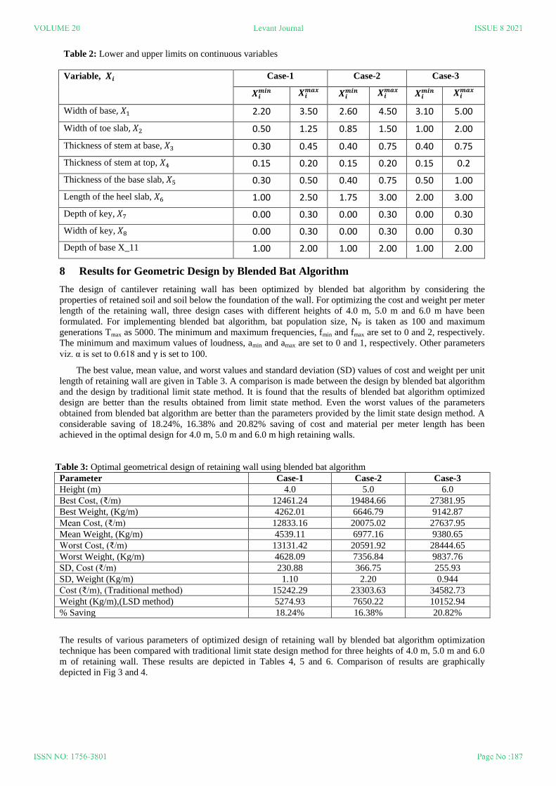
Table 2: Lower and upper limits on continuous variables
Variable, Case-1 Case-2 Case-3
Width of base, 2.20 3.50 2.60 4.50 3.10 5.00
Width of toe slab, 0.50 1.25 0.85 1.50 1.00 2.00
Thickness of stem at base, 0.30 0.45 0.40 0.75 0.40 0.75
Thickness of stem at top, 0.15 0.20 0.15 0.20 0.15 0.2
Thickness of the base slab, 0.30 0.50 0.40 0.75 0.50 1.00
Length of the heel slab, 1.00 2.50 1.75 3.00 2.00 3.00
Depth of key, 0.00 0.30 0.00 0.30 0.00 0.30
Width of key, 0.00 0.30 0.00 0.30 0.00 0.30
Depth of base X_11 1.00 2.00 1.00 2.00 1.00 2.00
8 Results for Geometric Design by Blended Bat Algorithm
The design of cantilever retaining wall has been optimized by blended bat algorithm by considering the
properties of retained soil and soil below the foundation of the wall. For optimizing the cost and weight per meter
length of the retaining wall, three design cases with different heights of 4.0 m, 5.0 m and 6.0 m have been
formulated. For implementing blended bat algorithm, bat population size, NP is taken as 100 and maximum
generations Tmax as 5000. The minimum and maximum frequencies, fmin and fmax are set to 0 and 2, respectively.
The minimum and maximum values of loudness, amin and amax are set to 0 and 1, respectively. Other parameters
viz. α is set to 0.618 nd is set to 100.
The best value, mean value, and worst values and standard deviation (SD) values of cost and weight per unit
length of retaining wall are given in Table 3. A comparison is made between the design by blended bat algorithm
and the design by traditional limit state method. It is found that the results of blended bat algorithm optimized
design are better than the results obtained from limit state method. Even the worst values of the parameters
obtained from blended bat algorithm are better than the parameters provided by the limit state design method. A
considerable saving of 18.24%, 16.38% and 20.82% saving of cost and material per meter length has been
achieved in the optimal design for 4.0 m, 5.0 m and 6.0 m high retaining walls.
Table 3: Optimal geometrical design of retaining wall using blended bat algorithm
Parameter Case-1 Case-2 Case-3
Height (m) 4.0 5.0 6.0
Best Cost, (₹/m) 12461.24 19484.66 27381.95
Best Weight, (Kg/m) 4262.01 6646.79 9142.87
Me n Cost, (₹/m) 12833.16 20075.02 27637.95
Mean Weight, (Kg/m) 4539.11 6977.16 9380.65
Worst Cost, (₹/m) 13131.42 20591.92 28444.65
Worst Weight, (Kg/m) 4628.09 7356.84 9837.76
SD, Cost (₹/m) 230.88 366.75 255.93
SD, Weight (Kg/m) 1.10 2.20 0.944
Cost (₹/m), (Tr dition l method) 15242.29 23303.63 34582.73
Weight (Kg/m),(LSD method) 5274.93 7650.22 10152.94
% Saving 18.24% 16.38% 20.82%
The results of various parameters of optimized design of retaining wall by blended bat algorithm optimization
technique has been compared with traditional limit state design method for three heights of 4.0 m, 5.0 m and 6.0
m of retaining wall. These results are depicted in Tables 4, 5 and 6. Comparison of results are graphically
depicted in Fig 3 and 4.

Fig 3: Variation of cost with height of retaining wall using LSD method and blended bat algorithm
Fig 4: Variation of weight with height of retaining wall using LSD method and blended bat algorithm
0
5000
10000
15000
20000
25000
30000
35000
4 5 6
Cost ₹/m
len
gth
Height in meters
Cost by Bat algorithm Cost by LSD method
0
2000
4000
6000
8000
10000
12000
1 2 3
Wei
gh
t k
g/m
len
gth
Height in meters
Weight by Bat algorithm Weight by LSD method

Table 4: Comparison between design parameters by blended bat algorithm and LSD method: Case-1
Parameter Limit State Design Method Optimized Design with blended bat algorithm
Best Design Worst Design
Cost (₹/m) 15242.29 12461.24 13131.42
Weight (Kg/m) 5274.93 4262.01 4628.09
(m) 2.550 2.305 2.332
(m) 0.850 0.929 1.053
(m) 0.400 0.358 0.324
(m) 0.1500 0.172 0.171
(m) 0.350 0.320 0.394
(m) 1.700 1.378 1.378
(m) 0.300 0.123 0.145
(m) 0.300 0.032 0.166
(m) 1.25 1.949 1.529
Table 5: Comparison between design parameters by blended bat algorithm and LSD method: Case-2
Parameter Limit State Design
Method
Optimized Design with blended bat algorithm
Best Design Worst Design
Cost (₹/m) 23303.63 19484.66 20591.92
Weight (Kg/m) 7650.22 6646.79 7356.84
(m) 3.150 2.927 2.793
(m) 1.050 1.174 1.038
(m) 0.450 0.416 0.515
(m) 0.150 0.167 0.168
(m) 0.450 0.440 0.470
(m) 2.100 1.750 1.750
(m) 0.3000 0.066 0.220
(m) 0.3000 0.145 0.259
(m) 1.25 m 1.485 1.832
Table 6: Comparison between design parameters by blended bat algorithm and LSD method: Case-3
Parameter Limit State Design
Method
Optimized design with blended bat algorithm
Best Design Worst Design
Cost (₹/m) 34582.73 27381.95 28444.65
Weight (Kg/m) 10152.94 9142.87 9837.76
(m) 3.750 3.507 3.687
(m) 1.250 1.510 1.696
(m) 0.450 0.517 0.539
(m) 0.150 0.170 0.167
(m) 0.550 0.500 0.516
(m) 2.500 2.000 2.004
(m) 0.300 0.108 0.171
(m) 0.300 0.247 0.250
(m) 1.25 1.800 1.800
Effect of back slope angle on cost and weight
Cost per meter length with respect to backfill slope, θo has been observed by varying the value of angle of
retained soil from 0o to 25o in steps of 5o for all the three-design cases of retaining wall as given in Table 7. Fig 5
demonstrates the increase in cost with the increase of backfill slope.

Table 7: Variation of cost with the angle of backfill slope using blended bat algorithm
Angle of backfill slope,
θo
Cost (₹/m)
Case-1 Case-2 Case-3
0 o 11407.89 18629.55 26059.84
5 o 12020.42 18597.29 26462.90
10 o 12313.16 19025.97 26721.29
15 o 12461.24 19484.66 27381.95
20 o 12521.46 19660.89 27648.25
25 o 12903.46 21048.24 29221.63
Variation % 13.11% 13.17% 12.13%
Fig 5: Variation of cost with the angle of backfill slope using blended bat algorithm
The outcome of variation of weight of ret ining w ll per meter length with reg rd to b ckfill slope θo is
shown in Table 8. The angle of backfill was varied from 0o to 25o in an increment of 5o for all the three-design
cases. The weight of material increases with the increase of backfill slope as depicted in Fig 6.
Table 8: Variation of weight with the angle of backfill slope using blended bat algorithm
Angle of backfill slope,
θo
Weight (kg/m)
Case-1 Case-2 Case-3
0 o 4120.22 6487.23 8924.43
5 o 4222.61 6426.40 8849.48
10 o 4263.35 6474.37 8788.33
15 o 4262.01 6646.79 9142.87
20 o 4217.36 6418.85 9057.64
25 o 4313.56 7066.65 9583.48
Variation % 4.69% 8.93% 7.38%
5000
10000
15000
20000
25000
30000
0 5 10 15 20 25
Cost ₹/ m len
gth
Angle of slope of retained soil in degrees
4m height 5m height 6m height
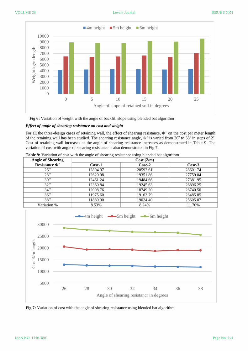
Fig 6: Variation of weight with the angle of backfill slope using blended bat algorithm
Effect of angle of shearing resistance on cost and weight
For all the three-design cases of retaining wall, the effect of shearing resistance, on the cost per meter length
of the retaining wall has been studied. The shearing resistance angle, is varied from 26o to 38o in steps of 2o.
Cost of retaining wall increases as the angle of shearing resistance increases as demonstrated in Table 9. The
variation of cost with angle of shearing resistance is also demonstrated in Fig 7.
Table 9: Variation of cost with the angle of shearing resistance using blended bat algorithm
Angle of Shearing
Resistance Cost (₹/m)
Case-1 Case-2 Case-3
26 o 12894.97 20592.61 28601.74
28 o 12620.08 19351.86 27759.04
30 o 12461.24 19484.66 27381.95
32 o 12360.84 19245.63 26896.25
34 o 12098.76 18749.20 26740.50
36 o 11975.60 19163.79 26485.85
38 o 11880.90 19024.40 25605.07
Variation % 8.53% 8.24% 11.70%
Fig 7: Variation of cost with the angle of shearing resistance using blended bat algorithm
0
1000
2000
3000
4000
5000
6000
7000
8000
9000
10000
0 5 10 15 20 25
Wei
ght
kg
/m l
eng
th
Angle of slope of retained soil in degrees
4m height 5m height 6m height
5000
10000
15000
20000
25000
30000
26 28 30 32 34 36 38
Cost ₹/m
len
gth
Angle of shearing resistancr in degrees
4m height 5m height 6m height

Table 10: Variation of weight with the angle of shearing resistance using blended bat algorithm
Angle of Shearing
Resistance Weight (kg/m)
Case-1 Case-2 Case-3
26 o 4381.84 6881.90 9571.50
28 o 4419.87 6413.61 9314.97
30 o 4262.01 6646.79 9142.87
32 o 4262.97 6609.67 8929.21
34 o 4342.72 6429.44 8722.39
36 o 4225.90 6704.90 8855.70
38 o 4213.37 6702.12 8412.63
Variation % 3.69% 2.68% 13.77%
Table 10 depicts similar variation in the weight per meter length when angle of shearing resistance, is
increased from 26o to 38o at an interval of 2o. The weight of retaining wall decreases with the increase in the
shearing resistance, which is evident from Fig 8. Effect of angle of shearing resistance on weight/ m length is
more significant for greater height of 6 m as compare to smaller height of 5 m and 4 m.
Fig 8: Variation of weight with the angle of shearing resistance using blended bat algorithm
Effect of base friction on cost and weight
The cost of retaining wall per meter length with respect to base friction has been observed by increasing the
value of base friction coefficient from 0 to 0.6 in steps of 0.1 for three cases of design and is depicted in Table
11. It is observed from Fig 9 that with the increase of base friction the cost of material per meter length of
retaining wall decreases by a small margin in the range of 0.8% to 2.0% only.
Table 11: Variation of Cost with the angle of base friction using blended bat algorithm
Base Friction,
Cost (₹/m)
Case-1 Case-2 Case-3
0 12562.78 19748.13 27942.52
0.1 12461.24 19529.93 27766.61
0.2 12461.24 19484.66 27546.24
0.3 12461.24 19484.66 27381.95
0.4 12461.24 19484.66 27381.95
0.5 12461.24 19484.66 27381.95
0.6 12461.24 19484.66 27381.95
Variation % 0.81% 1.35% 2.04%
0
1000
2000
3000
4000
5000
6000
7000
8000
9000
10000
26 28 30 32 34 36 38
wei
gh
t k
g/m
len
gth
Angle of shearing resistance in degrees
4m height 5m height 6m height

Fig 9: Variation of cost with base friction using blended bat algorithm
Similarly, Table 12 shows the variation of weight of retaining wall with respect to base friction. It has been
observed that by increasing the value base friction, from 0 to 0.6, weight of retaining wall per meter length first
decreases, but only by a very small amount (0.8% to 2.0%) and then becomes constant. These results are
graphically represented in Fig 10.
Table 12: Variation of weight with base friction using blended bat algorithm
Base Friction,
Weight (kg/m)
Case-1 Case-2 Case-3
0 4296.53 6830.52 9330.04
0.1 4262.01 6755.05 9216.01
0.2 4262.01 6646.79 9197.70
0.3 4262.01 6646.79 9142.87
0.4 4262.01 6646.79 9142.87
0.5 4262.01 6646.79 9142.87
0.6 4262.01 6646.79 9142.87
Variation % 0.79% 2.76% 2.04%
10000
12000
14000
16000
18000
20000
22000
24000
26000
28000
30000
0 0.1 0.2 0.3 0.4 0.5 0.6
Cost ₹/m
len
gth
Base friction
4m height 5m height 6m height
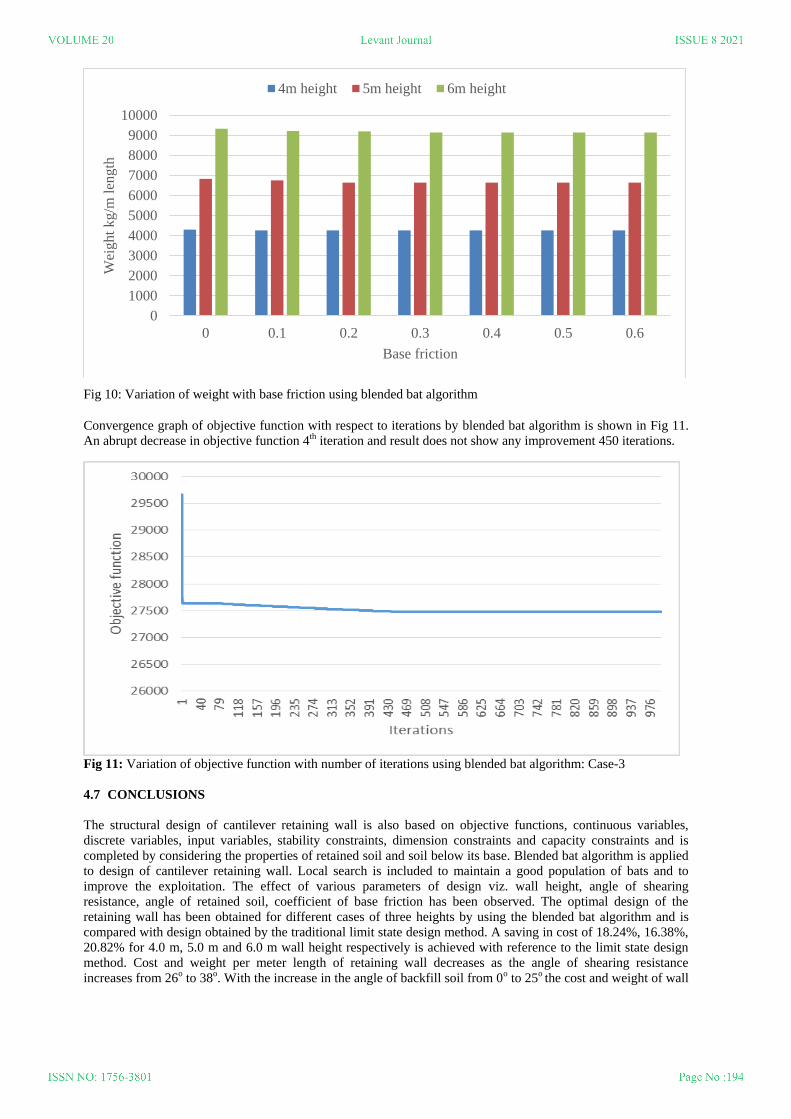
Fig 10: Variation of weight with base friction using blended bat algorithm
Convergence graph of objective function with respect to iterations by blended bat algorithm is shown in Fig 11.
An abrupt decrease in objective function 4th iteration and result does not show any improvement 450 iterations.
Fig 11: Variation of objective function with number of iterations using blended bat algorithm: Case-3
4.7 CONCLUSIONS
The structural design of cantilever retaining wall is also based on objective functions, continuous variables,
discrete variables, input variables, stability constraints, dimension constraints and capacity constraints and is
completed by considering the properties of retained soil and soil below its base. Blended bat algorithm is applied
to design of cantilever retaining wall. Local search is included to maintain a good population of bats and to
improve the exploitation. The effect of various parameters of design viz. wall height, angle of shearing
resistance, angle of retained soil, coefficient of base friction has been observed. The optimal design of the
retaining wall has been obtained for different cases of three heights by using the blended bat algorithm and is
compared with design obtained by the traditional limit state design method. A saving in cost of 18.24%, 16.38%,
20.82% for 4.0 m, 5.0 m and 6.0 m wall height respectively is achieved with reference to the limit state design
method. Cost and weight per meter length of retaining wall decreases as the angle of shearing resistance
increases from 26o to 38o. With the increase in the angle of backfill soil from 0o to 25o the cost and weight of wall
0
1000
2000
3000
4000
5000
6000
7000
8000
9000
10000
0 0.1 0.2 0.3 0.4 0.5 0.6
Wei
ght
kg
/m l
eng
th
Base friction
4m height 5m height 6m height

increases with the increase in base friction value from 0.0 to 0.6, the cost and weight of retaining wall decreases
initially and then become constant. So optimal design by blended bat algorithm is better than the design by limit
state method.
Acknowledgments
The corresponding author wish to thank GZS CCET, MRSPTU, Bathinda and I.K. Gujral, Punjab Technical
University, Jalandhar (Punjab), for providing advanced research facilities during research work.
Conflict of Interest
The authors have no conflicts of interest to declare that are relevant to the content of this article.
Data Availability Statement
All data, models, and code generated or used during the study appear in the submitted article in sections 6 and 7
and in Tables 1 and 2.
References:
1. Amin M nouchehri n, J v d Ghol mnej d, Most f Sh rifz deh, (2014), “Development of Model for
An lysis of Slope St bility for Circul r Mode F ilure using Genetic Algorithm,” Environment l E rth
Sciences, 71 (3), pp 1267–1277.
2. Bouss ıd, I., Ch tterjee, A., Siarry, P., and Ahmed-N cer, M., (2011), “Two-Stage Update Biogeography-
B sed Optimiz tion using Differenti l Evolution Algorithm (DBBO),” Computers nd Oper tions
Research, 38, pp. 1188–1198.
3. G ndomi A.H, Y ng X.S, Al vi A.H, nd T l t h ri S, (2013), “B t Algorithm for Constr ined
Optimiz tion T sks”, Neur l Computing & Applic tions, 22, pp. 1239-1255.
4. G ndomi A. H., K sh ni A. R., Mous vi M., J l lv ndi M., (2014), “Slope St bility An lysis using
Recent Sw rm Intelligence Techniques”, Intern tion l Journ l for Numeric l nd An lytic l Methods in
Geo-Mechanics, 39(3).
5. H s nçebi, O., nd C rb s, S. (2014), “B t Inspired Algorithm for Discrete Size Optimiz tion of Steel
Fr mes”, Adv nces in Engineering Software, 67, pp. 173-185.
6. K veh, A., nd Ab di A. S. M., (2011), “H rmony Se rch B sed Algorithms for the Optimum Cost
Design of Reinforced Concrete C ntilever Ret ining W lls,” Intern tion l Journ l of Civil Engineering,
9(1). pp. 1-8
7. Kaveh A., nd Behn m A. F., (2013), “Ch rged System Se rch Algorithm for the Optimum Cost Design
of Reinforced Concrete C ntilever Ret ining W lls” Ar bi n Journ l for Science nd Engineering, 38(3),
pp. 563–570
8. Khajehzadeh M., Taha, M. R., El-Shafie A., and Eslami M., (2011), “Se rch for Critic l F ilure Surf ce in
Slope St bility An lysis by Gr vit tion l Se rch Algorithm,” Intern tion l Journ l of the Physic l
Sciences, 6(21), pp. 5012-5021.
9. Kh jehz deh M., nd Esl mi, M. (2012), “Gr vit tion l Se rch Algorithm for Optimization of Retaining
Structures”, Indi n Journ l of Science nd Technology, 5(1), pp.1821-1827.
10. Malkawi A. I. H., Hassan W. F. and Sarma S. K. (2001), “Glob l Se rch Method for Locating General
Slip Surf ce using Monte C rlo Techniques”, Journ l of Geotechnical and Geo-Environmental
Engineering, 127 (8), pp. 688-698.
11. Pei, Y. nd Xi , Y., (2012), “Design of Reinforced Cantilever Retaining Walls Using Heuristic
Optimiz tion Algorithms,” Proceeding of E rth nd Pl net ry Science, 5, pp. 32-36.
12. Poursh , M., Khoshnoudi n F., nd Mogh d m, A, (2011), “H rmony Se rch B sed Algorithms for the
Optimum Cost Design of Reinforced Concrete C ntilever Ret ining W lls,” Intern tion l Journ l of Civil
Engineering, 9, pp.1-8.
13. Sheikholeslami, R., Khalili, B. G., nd Z hr i, S. M., (2014), “Optimum Cost Design of Reinforced
Concrete Ret ining W lls using Hybrid Firefly Algorithm,” IACSIT Intern tion l Journ l of Engineering
and Technology, 6(6). pp. 465-473.
14. Simon D., (2008) “Biogeogr phy-B sed Optimiz tion”, IEEE Transactions on Evolutionary Computation,
12 (6), pp. 702 - 713.

15. Simon, D., Rarick, R., Ergezer, M. and Du, D., (2011), “An lytic l nd Numeric l Comp risons of
Biogeography-b sed Optimiz tion nd Genetic Algorithms”, ELSEVIER Journ l of Inform tion Sciences
181, pp. 1224–1248.
16. Sisworahardjo N.S. and El-Keib A. A., (2002), “Unit Commitment using the Ant Colony Se rch
Algorithm”, IEEE Proceedings L rge Engineering Systems Conference on Power Engineering, pp. 2-6.
17. Tsai P.W., Pan J.S., Liao B.Y., Tsai M. J., nd Ist nd V., (2012), “B t Algorithm Inspired Algorithm for
Solving Numerical Optimization Problems," Applied Mechanics and Materials, 148, pp. 134-137.
18. Venanzio R. Greco, (1996), Efficient Monte Carlo Technique for Locating Critical Slip Surface, Journal
of Geotechnical Engineering, 122 (7), pp. 517-525.
19. Villalba P., Alcalá J., Yepes V., and González-Vidosa F., (2010) “CO2 Optimiz tion of Reinforced
Concrete C ntilever Ret ining W lls,” 2nd Intern tion l Conference on Engineering Optimiz tion,
Lisbon, Portugal, pp.1-10.
20. Xiong, G., Shi, D., nd Du n, X., (2013), “Multi-Strategy Ensemble Biogeography-Based Optimization
for Economic Disp tch Problems,” Applied Energy, 111, pp. 801-811.
21. Xiong, G., Shi, D., nd Du n, X., (2014), “Enh ncing the Perform nce of Biogeogr phy-Based
Optimiz tion using Polyphyletic Migr tion Oper tor nd Orthogon l Le rning,” Computers nd
Operations Research, 41, pp. 125-139.
22. Y ng X. S., (2010), “A New Met -Heuristic Bat-Inspired Algorithm,” N ture Inspired Cooper tive
Str tegies for Optimiz tion”, (NICSO 2010), pp. 6315-6374.
23. Yepes, V., Gonzalez-Vidos F., Alc l M. J., nd Vill lb P., (1997), “CO2-Optimization Design of
Reinforced Concrete Retaining Walls based on a VNS-Threshold Accept nce Str tegy,” Journ l of
Computing in Civil Engineering, 26(3):378-386.
24. IS 456: 2000, “Pl in nd Reinforced Concrete Code of Pr ctice”, Bure u of Indian Standards Manak
Bhavan, New Delhi.
25. Harman M., and McMinn P. (2010) “A theoretical and empirical study of search–based testing: local,
global and hybrid search”, IEEE Transactions on Software Engineering, 36 (2): 226–47.
26. Wolpert D.H., and Macready W.G. (1997) No free lunch theorems for optimization. IEEE Transactions on
Evolution Computation, 1(1): 67–82.
27. Yang X.S., and He X. (2013) “Bat algorithm: literature review and applications”, International Journal of
Bio-Inspired Computation, 5(3):141-9.