(blank reverse)
TRANSCRIPT

A DESIGN TOOL FOR THE EVALUATION OF ATMOSPHERE
INDEPENDENT PROPULSION IN SUBMARINES
by
Grant B. Thomton, LCDR, USN
B.S., Marine EngineeringUnited States Naval Academy, 1979
SUBMITTED TO THE DEPARTMENTS OF OCEAN ENGINEERINGAND MECHANICAL ENGINEERING IN PARTIAL FULFILMENT
OF THE REQUIREMENTS FOR THE DEGREES OF
MASTER OF SCIENCE IN NAVAL ARCHITECTURE AND MARINE ENGINEERING
and
MASTER OF SCIENCE IN MECHANICAL ENGINEERING
at the
MASSACHUSETTS INSTITUTE OF TECHNOLOGY
May 1994
Copyright © 1994 Grant B. Thomton
The author hereby grants to MIT permission to reproduce and to distributepublicly paper and electronic copies of this thesis document in whole or in part.
Signature of Author ... . . - -
.,/../ ~-u-_:.-.;Departments of Ocean and Mechanical EngineeringMay 6, 1994
Certified byProfessor David Gordon Wilson
Thesis Reader- . Department of Mechanical Engineering
Accepted b!y"-----' Prfess A. Douglas Carmichael
Thesis Advisor andChairma0, Jepartment Committee on Graduate Students
,W1IT ;.- ^.-- .;,: Department of Ocean Engineering
~:'~!i": ~JUN 2' i '" '-1994JUN 2 0 1994
Lonn_;:>

(Blank Reverse)
2
A DESIGN TOOL FOR THE EVALUATION OF ATMOSPHERE
INDEPENDENT PROPULSION IN SUBMARINES
by
Grant Blount Thornton
Submitted to the Departments of Ocean Engineering and MechanicalEngineering on May 6, 1994 in partial fulfilment of the requirements
for the Degrees of Master of Science in Naval Architecture andMarine Engineering and Master of Science in Mechanical Engineering.
ABSTRACT
For the United States Navy, submarine propulsion has long since evolved fromDiesel Electric to a complete reliance on Nuclear Power. Nuclear propulsion is theultimate atmosphere independent power source, allowing the submarine to divorceitself from the surface, limited only by the endurance of the crew embarked.
Submarine construction and operating costs have grown dramatically, duelargely to the cost of the high performance nuclear propulsion plant. Other optionsexist to provide Atmosphere Independent Propulsion of similar capability for extendedunderwater periods at a potentially lower cost.
This thesis explores the aspects of non-nuclear atmosphere independentpropulsion as an integral part of the submarine design process, focusing on methodsfor power generation and various options for fuel and oxidant storage.
Fuel sources include pure hydrogen, stored cryogenically or in metal hydrides,or more common fuels such as diesel or methanol, used either directly or in a reformedstate. Oxidants include pure oxygen, stored cryogenically or in compressed form, aswell as hydrogen peroxide and sodium perchlorate. Energy conversion methodsexamined include mechanical such as closed cycle diesels, Brayton cycles and Stirlingengines, to electro-chemical designs, such as fuel cells and aluminum oxygen semi-cells.
A computer code was written which integrates these propulsion options withmission and owner's requirements to provide a balanced design in terms of matchingthe weights and volumes of the equipment installed. This code will serve as a tool forthe concept design of non-nuclear air independent submarines.
Thesis Supervisor: A. Douglas Carmichael, Professor of Ocean Engineering
Thesis Reader: David Gordon Wilson, Professor of Mechanical Engineering
3

(Blank Reverse)
4
ACKNOWLEDGEMENTS
I wish
for reference
to acknowledge the following persons who aided me in my search
material:
Dave Bagley
Mark Cervi
Henry DeRonck
LCDR Norbert Doerry
Richard Martin
Warren Reid
Ed Robinson
Steve Sinsabaugh
LT Cliff Whitcomb
I hope that I have correctlyavailable to me.
NSWC Annapolis
NSWC Annapolis
International Fuel Cells
NAVSEA
Draper Laboratory
NSWC Annapolis
NAVSEA PEO SUB-R
LORAL Defense Industries
NSWC Carderock
interpreted the information that you made
I am grateful for the counsel in ship and submarine design provided by
Professors Alan Brown and Jeff Reed in the Naval Construction and Engineering
Program at MIT.
I wish to thank my Thesis Advisor, Professor A. D. Carmichael who
inspired me to investigate the realm of Air Independent Propulsion as a student,
who stood by me as I worked to put my research together in an orderly fashion,
and who taught me to be aware of the salesman and the customer when
evaluating data.
But most of all, I am thankful for the love and understanding of my family;
Daryl, David and Megan, as I complete my studies at MIT.
5

(Blank Reverse)
6

TABLE OF CONTENTS
ABSTRACT
ACKNOWLEDGEMENTS
TABLE OF CONTENTS
LIST OF FIGURES .
LIST OF TABLES
CHAPTER ONE1.0 Introduction
1.1 History1.2 Air Independence Concept1.3 Propulsion Options1.4 Thesis Objective
CHAPTER TWO2.0 The Design Process
2.1 Mission Requirements.2.2 Required Operational Capabilities2.3 Submarine Hull Synthesis
CHAPTER THREE3.0 Submarine Systems
3.1 Propulsion Integration .3.1.1 Conventional DC3.1.2 Permanent Magnet AC3.1.3 Superconducting Homopolar DC3.1.4 Propulsors
3.2 Ship Service Power Requirements3.3 Auxiliary Systems3.4 Atmosphere Control
CHAPTER FOUR4.0 Power Sources .
4.1 Electro-Chemical Concepts4.1.1 Fuel Cells
4.1.1.1 Proton Exch. Membrane Fuel Cells4.1.1.2 Alkaline Fuel Cells4.1.1.3 Phosphoric Acid Fuel Cells4.1.1.4 Molten Carbonate Fuel Cell4.1.1.5 Solid Oxide Fuel Cell4.1.1.6 Direct Methanol Oxidation Fuel Cell
4.1.2 Aluminum Oxygen Semi-Cell4.1.3 Batteries
4.1.3.1 Lead Acid Batteries4.1 .3.2 Nickel-Cadmium Batteries
7
35
7
13
17
1919202121
25272933
373838404244444646
51525254575758606062646568

(Blank Reverse)
8

4.1.3.3 Silver-Zinc . .704.1.3.4 Lithium-Aliminum / Iron Sulfide 72
4.2 Mechanical Power Sources 744.2.1 Closed Cycle Engines 74
4.2.1.1 Closed Cycle Diesel 744.2.1.2 Closed Brayton Cycle 77
4.2.2 Stirling Engine 794.2.3 Other Power Cycles. . . . 80
4.2.3.1 Rankine Cycle 814.2.3.2 Small Nuclear Power 834.2.3.3 Walter Cycle 83
CHAPTER FIVE5.0 Reactants 87
5.1 Fuels 885.1.1 Hydrogen 88
5.1.1.1 Hydrogen - Gaseous Storage 895.1.1.2 Hydrogen - Cryogenic Storage 895.1.1.3 Hydrogen - Metal Hydride 905.1.1.4 Hydrogen - By Reformation 92
5.1.2 Other Fuels 945.2 Oxidants. 95
5.2.1 Oxygen 955.2.1.1 Oxygen - Gaseous Storage 955.2.1.2 Oxygen - Cryogenic Storage 965.2.1.3 Oxygen - Chemical Reformation. 985.2.1.4 Oxygen - Generation Onboard . 99
5.2.2 High Test Hydrogen Peroxide 995.3 Waste Products 101
CHAPTER SIX6.0 The Submarine Model. 105
6.1 Hull Envelope . 1066.2 Volume Estimates 107
6.2.1 Pressure Hull Volume 1076.2.1.1 Mobility Volume 1076.2.1.2 Weapons and C31 Volume 1086.2.1.3 Ship Support Volume 108
6.2.2 Other Volumes 1096.3 Weight Estimates 110
6.3.1 Surfaced Displacement 1116.3.1.1 Structural Weight . 1116.3.1.2 Mobility Weight 1116.3.1.3 Weapons and C31 Weight 1126.3.1.4 Ship Support Weight 1126.3.1.5 Fixed Ballast and Variable Load Wt 113
9

(Blank Reverse)
10

6.4 Powering and Edurance6.4.1 Powering
6.4.1.1 Hydrodynamics6.4.1.2 Propulsion Motor Turndown
6.4.2 Snort Power and Bunker Fuel Calculation6.4.3 Hotel Loads6.4.4 Battery Endurance
6.5 The AIP Plant
CHAPTER SEVEN7.0 Computer Code Development
7.1 Overview
CHAPTER EIGHT8.0 Results and Conclusions
8.1 Model Validation8.2 General Results
8.2.1 Overall AIP Impact8.2.2 Impact of Reactants .8.2.3 Impact of Other Technologies
8.3 Ship Trade-offs.
CHAPTER NINE9.0 Areas for Future Study
REFERENCES
APPENDIX A
APPENDIX B
APPENDIX C
APPENDIX D
APPENDIX E
APPENDIX F
APPENDIX G
APPENDIX H
- POWER SOURCE DOCUMENTATION
- REACTANT DOCUMENTATION
- BASELINE MODEL
- HULL ENVELOPE
- VOLUME DATA BASE
- WEIGHT DATA BASE
- SNORKEL POWERING
- RESULT DATA TABLES.
APPENDIX I - COMPUTER CODE
11
114114114117117118119120
121121
125125127128130132135
139
141
147
163
175
191
195
201
205
207
211

(Blank Reverse)
12
LIST OF FIGURES
2.1 Acquisition Milestones and Phases 262.2 The Design Spiral . 272.3 Balancing Weights and Volumes . 353.1 Battery Stepping Operating Modes for a Double Armature DC Mtr 393.2 Permanent Magnet Axial Gap Propulsion Motor 403.3 Permanent Magnet High Speed Generator 413.4 Example of Chopped AC Output from Input DC. 423.5 Superconducting Homopolar DC Motor . 433.6 Typical Ship Service Distribution System 453.7 Hydraulic System with Typical Loads 473.8 High Pressure Air System . 473.9 Ventilation Arrangement 494.1 Efficiency vs. Load for AIP Options 534.2 Proton Exchange Membrane Fuel Cell 554.3 PEM Cell Voltage vs. Cell Load 564.4 Molten Carbonate Fuel Cell 594.5 Westinghouse Solid Oxide Fuel Cell 614.6 Aluminum Oxygen Semi-Cell 634.7 Lead Acid Battery Schematic 674.8 Typical Lead Acid Discharge Characteristics 674.9 Nickel-Cadmium Discharge Characteristics 704.10 Silver Zinc Discharge Characteristics 724.11 LAIS Battery Discharge Characteristics . 744.12 Closed Cycle Diesel with Exhaust Management System 764.13 Closed Brayton Cycle Combustion Power System 784.14 Closed Brayton Cycle Schematic Flow Diagram 794.15 Stirling Operating Cycle 814.16 MESMA Operating Cycle . 824.17 AMPS Power Cycle. . . . . . . 844.18 Walter Power Cycle. 855.1 Metal Hydride Storage in Ex-U1 (German Type 205) . 915.2 Hydrogen Content of Various Fuels 945.3 Torroidal Gaseous Oxygen Storage Concept 965.4 44 Inch UUV Oxygen Supply Concept 985.5 Comparison of Oxidant Storage Methods 1005.6 Liquid / Gas Flow Mixer . . . . . 1025.7 Cosworth Exhaust Management System. 1036.1 The Submarine Envelope . .....106
7.1 "SUBSIZE" Flowchart . . . . . . 122
13

(Blank Reverse)
14

8.1 Comparison of Canadian Hybrid Submarine and SUBSIZE Results 1268.2 Comparison of AIP Plants . 1298.3 AIP Plant Variation with Endurance 1298.4 Comparison of Oxidant Storage Methods 1318.5 Comparison of Hydrogen Storage Methods 1318.6 Comparison of Battery Options with Fixed Creep Endur. Reqm't 1328.7 Comparison of Battery Options with Fixed Burst Endur. Reqm't 1338.8 Effect of Propulsive Coefficient on NSC . 1348.9 Effect of L/D Ratio on NSC and SHP 1358.10 Effect of AIP Speed on NSC 136A. 1 Ni/Cd vs. Discharge Rate . 160
B. 1 Liquid Oxygen Tank Arrangement 167C.1 Profile View of Baseline Submarine 176C.2 Chart of Propeller Efficiency 178D.1 The Body of Revolution Hull 192D.2 Effects of na and nfon Hull Geometry 193E.1 Mobility Density 197E.2 Torpedo Tube and Reload Density 197G.1 Wave Drag Coefficient 206
15

(Blank Reverse)
16

LIST OF TABLES
1.1 AIP Power Source and Reactant Options . . . 222.1 Comparison of AlP/Conventional Submarines . 302.2 Statement of Requirements 322.3 Design Philosophy . 33
3.1 Propulsion Options . 384.1 Electro-Chemical AIP Concepts . 524.2 Summary of Battery Types. 654.3 Mechanical AIP Concepts . 755.1 AIP Reactant Options 87
8.1 Comparison of AIP Plant Densities 1278.2 Effect of Propulsion Motor Type on NSC. 1348.3 Indiscretion Ratio and Speed of Advance 137
A. 1 Summary of Energy Conversion Devices 148B.1 Reactant Packing Factors . 164
C.1 Baseline Submarine Summary 177C.2 Summary of Propeller Characteristics 177C.3 Propeller Selection Spreadsheet . 179D.1 Selected Values for Cp and Csf . 193E. 1 Summary of Volume Data . 196
F. 1 Summary of Weight Data . 202
17

(Blank Reverse)
18
CHAPTER ONE
1.0 INTRODUCTION
1.1 HISTORY
The submarine, a dramatic addition to any country's naval arsenal, is well
documented throughout history. With modest beginnings as early as the Turtle
in the Revolutionary War [11], the importance of the submarine has grown as
technology has enabled the ship to develop greater agility and endurance in its
operations. Submersible boats, powered by diesel electric propulsion plants on
the surface and lead acid storage batteries submerged, were first used
extensively in combat during World War I by the German Navy where they were
very effective in sinking considerable military and civilian shipping in an attempt
to isolate England and her allies from the United States.
World War II brought more advanced ships into combat with similar
tactics as these ships were still not true submersibles. With a hull design more
akin to performance on the surface, these were still ships that operated largely
on the surface of the sea, only to submerge for their torpedo attack. Though the
Germans worked feverishly on developing new technologies to enable the
submarine to stay submerged longer, such as the snorkel and an air
independent power plant: the Walter Cycle, a carbon dioxide-steam Rankine
cycle powered by high test hydrogen peroxide [46], they were eventually
overcome by Allied tactics and superior strength. The United States submarine
force was also successful in their campaigns against the Japanese Empire.
Instrumental in holding the Japanese in check while the United States recovered
from the attack on Pearl Harbor, their heroic actions against military and
merchant shipping were critical to defeating the Japanese. Still the submarine
19

was a "surface ship" that dived to attack, and was limited in its ability to obtain
air from above to sustain propulsion beyond slow speeds on battery power.
The advent of nuclear power in the late 1950's brought a significant shift
in submarine design and use. With a power source that was truly divorced from
the surface, an emphasis was placed on underwater performance. Submarine
hull shapes similar to the now familiar tear drop "Albacore Hull" became
commonplace and tactics, sensors and weapons evolved that were designed to
be employed with the ship underwater. The price of nuclear power however is
not cheap. Not only was the cost of development expensive, but the necessary
infrastructure to build, maintain and train such a force limited its acceptance to
only a few nations with the necessary financial resources. This meant that those
countries that wished to continue to develop their own submarine fleets must
work on improving the "diesel boat" design.
1.2 AIR INDEPENDENCE CONCEPT
While submarine improvements can take many forms, this thesis will
concentrate on those which enhance propulsion endurance.
The concept of Air Independent Propulsion (AIP) can be defined many
ways, but will be taken here to mean propulsive power that is generated without
inducting an oxidant, air, from the atmosphere. Modern diesel electric
submarines seek to improve the amount of time that they can divorce from the
surface, which is accomplished by increasing the storage capacity of installed
secondary batteries and by decreasing the required submerged electrical load
through more power efficient equipment and reduced electric propulsion loads
(more efficient hull designs and propulsors). Modern diesel electric submarines
extend this time to many hours but usually at the expense of limiting the
submarine to slow speed and impacting the habitability of the crew. It is the AIP
20

concept that may enhance the performance of this capable diesel submarine
platform by extending this submerged endurance to many weeks, without
severely hampering the ship or the crew.
1.3 PROPULSION OPTIONS
Imagine any way to store any form of energy and to convert that stored
energy to electricity or mechanical work and you have a potential AIP source.
These ideas however must be tempered by common sense and the bounds of
what could conceivably placed in the hull of a submarine. Table 1.1 presents a
list of possible AIP power systems that have been proposed or developed,
divided into two areas: Power Sources and Reactants. All power sources must
consume some combination of reactants, usually a fuel and an oxidant to
provide power output. While nuclear power is considered the ultimate AIP
source due to its infinite (relative to any mission requirement) stored energy
capacity, only non-nuclear AIP sources will be considered in this thesis.
1.4 THESIS OBJECTIVE
Many nations desire the goal of unrestricted submarine operations, but
are unable or unwilling to make the step to nuclear power. Even the United
States, a world leader in safe and reliable nuclear propulsion may have cause to
consider returning to a mix of nuclear and non-nuclear submarines to perform its
assigned missions world-wide. The question becomes which one of the possible
AIP systems to choose and what will its impact be?
This thesis attempts to answer that question by development of a
computer model in "C++" to integrate the submarine design process with the
various propulsion plant options and reactant storage methods,
21

Table 1.1AIP Power Source and Reactant Options
Power Sources (Electro-Chemical Remarks
Proton Exchange Membrane Fuel Cell Most promising H.-O cell
Alkaline Fuel Cell Proven design
Phosphoric Acid Cell Proven design, low interest
Molten Carbonate Fuel Cell Mature commercial applications
Solid Oxide Fuel Cell Immature, highest projected efficiency
Aluminum Oxygen Semi-Cell Competitive with PEM cell
Lead Acid Battery Proven performance
Nickel Cadmium Battery Higher power density than lead acid
Lithium-Aluminum/Iron Sulfide Battery Potential successor to lead acid
Power Sources (Mechanical)
Closed Cycle Diesel Mature, lowest cost system
Stirling Engines Mature, low power only
Closed Brayton Cycles Excellent potential for development
Rankine Cycles Proven technology
Walter Cycles Safety of HO,
Reactants (Fuel)
Hydrogen Pure source, "hard to store"
Hydrocarbon Based Fuels With reformer-"best" hydrogen source
Reactants (Oxidants)
Oxygen Cryogenics best method
Hydrogen Peroxide Potentially unstable if concentrated
Chemical Reformation Competitive in some applications
22

including consideration of owners requirements for ship performance. Themodel will allow a user to input various performance criteria such as range,maximum speed, AIP endurance, select a type of AIP power plant and form of
reactant, and develop a balanced estimate of the required submarine size, in
terms of its principal dimensions as well as other submarine attributes such as
displacement, reserve buoyancy and lead margins. For the propulsion plant and
reactant options, the field was limited to those options which are currently in
development or which have had development work attempted, although other
options are mentioned.
23

(Blank Reverse)
24

CHAPTER TWO
2.0 THE DESIGN PROCESS
The ship procurement process is long and complex, employing many
different strategies and methods to achieve a final product that meets the needs
of the customer in terms of performance and cost. While there are as many
different ways to approach this problem as there are countries that attempt it,
they all share a common approach in that they:
- Identify requirements which result in a need for a ship
- Determine required capabilities
- Examine alternatives on paper
- Trade-off these alternatives using self imposed priorities
- Select a concept on which to do detailed design
- Construct the ship and measure its performance
- Evaluate the ship's success in terms of meeting statedrequirements
The United States Navy has adopted the format illustrated in Figure 2.1 for this
acquisition process. Each milestone represents a decision point where the work
from the previous phase is evaluated, and if appropriate a decision made to
proceed, with requirements established for the next phase. Each phase
represents a process where options are evaluated, and trade-off decisions made
to achieve the required level of detail for that design. This thesis supports
"Phase 0", the concept design phase of the design process.
Given the operational requirements set out by the owner, concepts to
meet these requirments are explored, then for the most viable concepts,
estimates are made of the required volume and weight for a ship meeting these
25
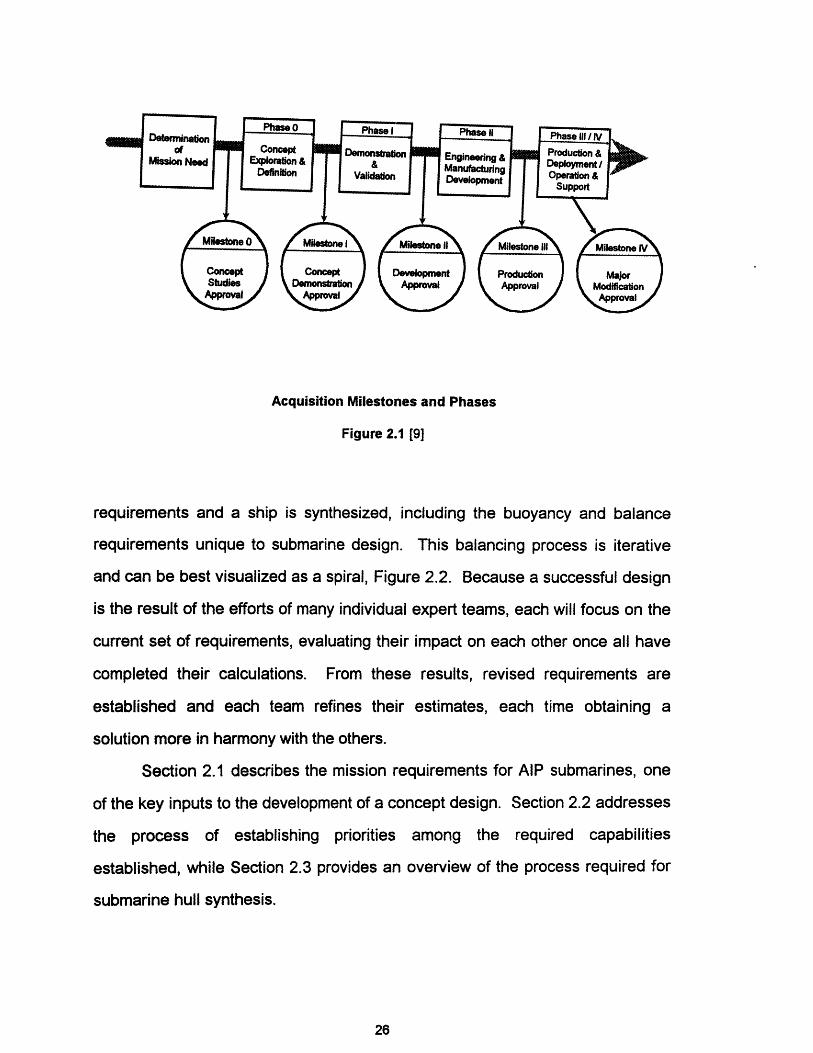
Acquisition Milestones and Phases
Figure 2.1 [9]
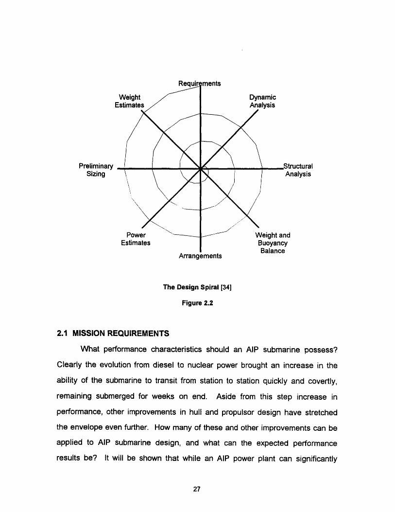
requirements and a ship is synthesized, including the buoyancy and balance
requirements unique to submarine design. This balancing process is iterative
and can be best visualized as a spiral, Figure 2.2. Because a successful design
is the result of the efforts of many individual expert teams, each will focus on the
current set of requirements, evaluating their impact on each other once all have
completed their calculations. From these results, revised requirements are
established and each team refines their estimates, each time obtaining a
solution more in harmony with the others.
Section 2.1 describes the mission requirements for AlP submarines, one
of the key inputs to the development of a concept design. Section 2.2 addresses
the process of establishing priorities among the required capabilities
established, while Section 2.3 provides an overview of the process required for
submarine hull synthesis.
26
PreliminarySizing
Arrangements
The Design Spiral [34]
Figure 2.2
2.1 MISSION REQUIREMENTS
What performance characteristics should an AIP submarine possess?
Clearly the evolution from diesel to nuclear power brought an increase in the
ability of the submarine to transit from station to station quickly and covertly,
remaining submerged for weeks on end. Aside from this step increase in
performance, other improvements in hull and propulsor design have stretched
the envelope even further. How many of these and other improvements can be
applied to AIP submarine design, and what can the expected performance
results be? It will be shown that while an AIP power plant can significantly
27

improve the performance of a conventional submarine when compared to a
nuclear powered submarine, the current state of AIP technology places limits on
key parameters such as patrol speed, burst speed, and submerged endurance.
When the United States committed itself to an all nuclear submarine
force, it adopted the philosophy that these ships should be multi-mission
capable. The LOS ANGLES class submarine exemplifies this mind set. Built for
speed, this class of submarine was enhanced to improve its ability to keep pace
with, and support a high speed carrier battle group, while maintaining the tools
necessary to perform other submarine missions. The addition of vertical launch
cruise missiles to the LOS ANGLES class has added yet another dimension to
this formidable platform. Estimated SEAWOLF capabilities echo this
commitment to a multi-mission platform.
It can be argued that the United States possesses the only true "blue
water" navy in the world, and perhaps the only one requiring a sustained, high
speed capability. Most nations with submarines are concerned with defense of
their home waters, and have designed their navies accordingly. For example,
Sweden's submarines operate in the Baltic Sea which is nominally 200 nautical
miles (nm) wide with a maximum transit distance to patrol of 1000 nm. As a
result, Sweden has incorporated a low power (2-75 kW Stirling Engines) AIP
power plant in their submarine NAECKEN [20]. Canada has expressed interest
in a long range AIP capability for its next generation diesel submarine to enable
her to control the vast ocean basin underneath the Arctic ice cap, while Australia
requires a similar long range capability of 9,000 nm to patrol and defend her
expansive coastline [67, 68].
Missions compatible with the role of the submarine in the U S Navy
include:
28
- Peacetime Engagement (show the flag)
- Surveillance- Deterrence- Regional Sea Denial
- Precision Strike Warfare
- Ground Warfare Support
- Unrestricted Submarine Warfare [62]
All of these missions can be performed by an AIP capable submarine.
Table 2.1 summarizes the operational capabilities of several classes of
conventional and AIP capable submarines. Included in the table are designs
already in service, as well as several designs not yet proven at sea. The
operational characteristics of a LOS ANGELES class submarine are included for
comparison to illustrate the impact of nuclear power on submarine design. As
can be seen, many nations have settled on designs that are significantly smaller
than the LOS ANGLES class submarine. It is also interesting to note that the
conventional designs all have similar, albeit less capable operational
characteristics, indicating the current limits placed on submarine design by AIP
and/or diesel technology.
2.2 REQUIRED OPERATIONAL CAPABILITIES
In developing the actual concept design for a submarine, the "owner" or
sponsor for the ship must specify what requirements the ship must meet to be
considered an acceptable design. From the Milestone 0 approval for example,
specific capabilities would be matched to the required missions for the
submarine, Section 2.1 above, such as:
29

Table 2.1
Comparison of AlP/Conventional Submarines
a. Janes Fighting Ships 1990-91, Capt. Richard Sharpe OBE RN ed., London, England.
b. Stennard, J. K, Comparative Naval Architecture of Modem Foreign Submannes, Thesis, Ocean Engineering
Department, Massachusetts Institute of Technology, May 1988.
c. Anon., The WALRUS Launched-First of a New Class of Dutch SSK., The NavalArchitect, Royal Institute of Naval
Architects, London, England, January 1986.
d. Anon., Maritime Defence. Volume 8, Number 4, April 1983.
e. Anon., The Kockums Group, Advertising Supplement to Janes Defense Weekly, March 1994.
f. Australian Collins Class Submarine Takes Shape, The Naval Architect, Royal Institute of Naval Architects, London,
England, February 1993.
g. The A19 and Type 471 Submarines from Kockums, The Naval Architect, Royal Institute of Naval Architects, London,
England, May 1991.
30
Los Angeles Kilo Walrus Type 2400 Type 1700 Naecken Collins
Country US USSR Netherlands UK FGR Sweden Australia
(Info. Source) a a b c b d a e,f
Year in 1976 1980 1985 1986 1984 1980 1994
Service
Submerged 6,927 Ron 3,000 Iton 2,800 Iton 2400 Iton 2,350 Iton 1,085 Iton 2,450 Iton
Displacement 3,000(AIP)
Length 360 f 239.5 ft 223.1 f 230.6 ft 216.5 ft 182.1 ft 249.3 ft
Diameter 33 ft 31.2 It 27.6 ft 25 ft 23.9 ft 18 ft 26.2 ft
Diving Depth 1475 ft 1000 ft > 1000 ft >660 ft > 1000 It 1000 f > 1000 ft
Max. Subm. >30 knots 17 knots 20 knots 20 knots 25 knots 20 knots 20 knots
Speed
Shaft 35,000 hp 6,000 hp 6,900 hp 5,360 hp 6,600 hp 1,800 hp 6,000 hp
Horsepower
AIP Power Y N N N N Y Planned
Source Nuclear Stirling PEM/Stirling
Mission 90 days 45 days 70 days 49 days 70 days ??? ??? days
Length
Complement 133 men 45 men 50 men 44 men 35 men 19 men 42 men
Range Unlimited 9600 nm 10,000 nm 7,056 nm 10,000 nm ??? 9,000 nm
Torpedo 4 6 4 6 6 8 6
Tubes
Torpedo 22 18 24 12 20 12 ??
Reloads
Cruise Missile Y Y Y Y Y Y Y / Y N / Y N/Y Y Y
Mine Capable
Mission Capability
Surveillance Coastline and Open Ocean monitoring, Drug
Interdiction
Ground Warfare Seal Team Insertion and Recovery
Strike Warfare Launch Cruise Missiles against land targets
In meeting these capabilities, operational performance parameters will be
specified to give the naval architect measurable attributes upon which to base
the design. This "Statement of Requirements" will also provide a range of
acceptable values, from a "Goal" or optimum value for that characteristic to a
"Threshold" or minimum acceptable value. A ship that does not at least meet all
the threshold values established by the owner will generally not be accepted.
The range of values specified for each requirement provide the latitude
necessary for trading off capabilities. Table 2.2 illustrates a typical Statement of
Requirements for an AIP submarine.
The final piece of logic to be communicated in this statement of owner's
requirements is the priority to be assigned to the attributes which are mutually
exclusive of each other. This design philosophy is usually stated in some form
of hierarchy, assigning relative weights to the attribute the owner considers most
important. This concept is illustrated in Table 2.3.
With the required missions determined, the required capabilities in
several areas stated and the relative priority for meeting the desired capabilities
established, the design team can proceed with concept exploration.
As an example of the type of trade-offs to be made, consider submerged
endurance on the battery. For a given battery type, increasing endurance for a
given speed on battery power alone means increasing the battery size, weight
and cost. If the battery is larger, the ship size may have to be increased to
31
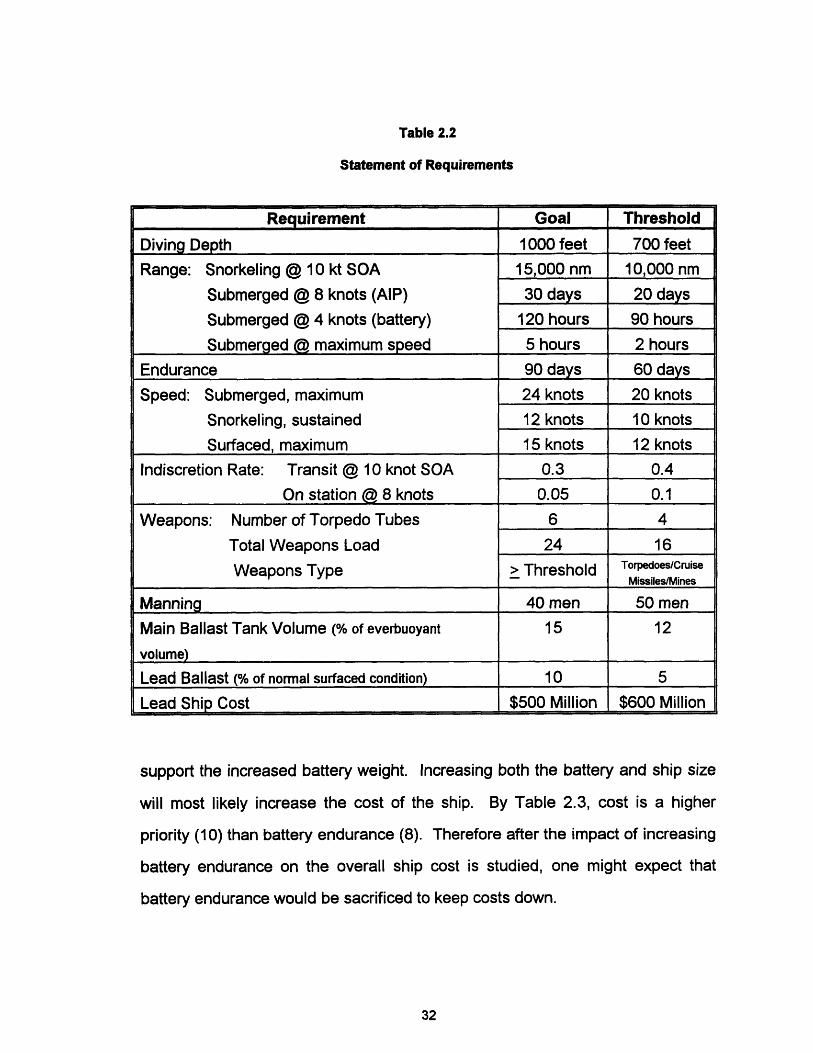
Table 2.2
Statement of Requirements
support the increased battery weight. Increasing both the battery and ship size
will most likely increase the cost of the ship. By Table 2.3, cost is a higher
priority (10) than battery endurance (8). Therefore after the impact of increasing
battery endurance on the overall ship cost is studied, one might expect that
battery endurance would be sacrificed to keep costs down.
32
Requirement Goal Threshold
Diving Depth 1000 feet 700 feet
Range: Snorkeling @ 10 kt SOA 15,000 nm 10,000 nm
Submerged @ 8 knots (AIP) 30 days 20 days
Submerged @ 4 knots (battery) 120 hours 90 hours
Submerged ( maximum speed 5 hours 2 hours
Endurance 90 days 60 days
Speed: Submerged, maximum 24 knots 20 knots
Snorkeling, sustained 12 knots 10 knots
Surfaced, maximum 15 knots 12 knots
Indiscretion Rate: Transit @ 10 knot SOA 0.3 0.4
On station 8 knots 0.05 0.1
Weapons: Number of Torpedo Tubes 6 4
Total Weapons Load 24 16
Weapons Type > Threshold Torpedoes/Cruise_eapons Type> Tresold Missiles/Mines
Manning 40 men 50 men
Main Ballast Tank Volume (% of everbuoyant 15 12
volume)
Lead Ballast (% of normal surfaced condition) 10 5
Lead Ship Cost $500 Million $600 Million

Table 2.3
Design Philosophy
2.3 SUBMARINE HULL SYNTHESIS
With the ships requirements stated, the process of determining the size of
the submarine can begin. While the details of the submarine model will be
discussed in Chapter 6, the basic concept of submarine hull generation will be
presented here to give a better understanding of the impact of the AIP
propulsion options, power sources and reactants on submarine design when
explained in Chapters 3, 4 and 5.
For this thesis, the shape of the hull will be assumed to be a body of
revolution, modeled after the hull of the submarine ALBACORE. This basic
shape has the best underwater hydrodynamic performance, which will be
important to best utilize the power available from the AIP power plant.
Even though a modern submarine is designed to spend most of its
operating time submerged, Archimedes' principle for flotation of hull weight is
applicable in both regimes. As seen in Figure 2.2, the first logical step from ship
33
Requirement Relative Weight
Mission Payload Performance 10
Cost 10
Maximum Speed 9
AIP Endurance 9
Battery Endurance 8
Risk 7
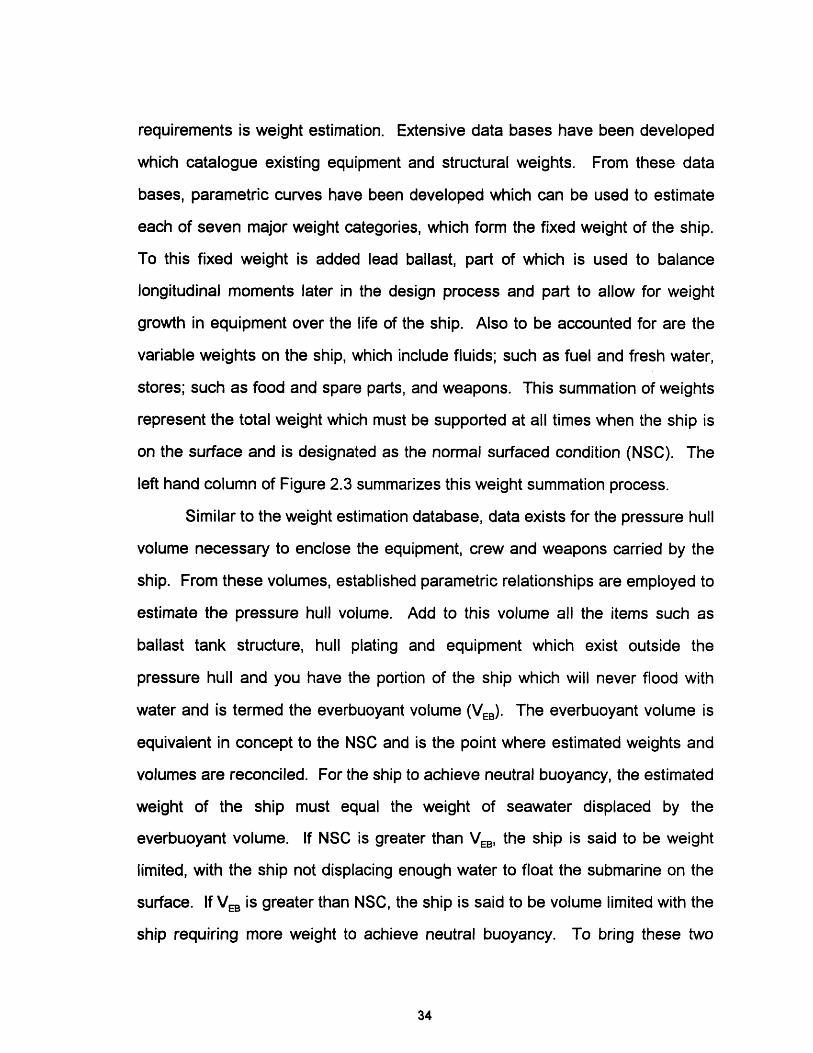
requirements is weight estimation. Extensive data bases have been developed
which catalogue existing equipment and structural weights. From these data
bases, parametric curves have been developed which can be used to estimate
each of seven major weight categories, which form the fixed weight of the ship.
To this fixed weight is added lead ballast, part of which is used to balance
longitudinal moments later in the design process and part to allow for weight
growth in equipment over the life of the ship. Also to be accounted for are the
variable weights on the ship, which include fluids; such as fuel and fresh water,
stores; such as food and spare parts, and weapons. This summation of weights
represent the total weight which must be supported at all times when the ship is
on the surface and is designated as the normal surfaced condition (NSC). The
left hand column of Figure 2.3 summarizes this weight summation process.
Similar to the weight estimation database, data exists for the pressure hull
volume necessary to enclose the equipment, crew and weapons carried by the
ship. From these volumes, established parametric relationships are employed to
estimate the pressure hull volume. Add to this volume all the items such as
ballast tank structure, hull plating and equipment which exist outside the
pressure hull and you have the portion of the ship which will never flood with
water and is termed the everbuoyant volume (VEB). The everbuoyant volume is
equivalent in concept to the NSC and is the point where estimated weights and
volumes are reconciled. For the ship to achieve neutral buoyancy, the estimated
weight of the ship must equal the weight of seawater displaced by the
everbuoyant volume. If NSC is greater than VEB, the ship is said to be weight
limited, with the ship not displacing enough water to float the submarine on the
surface. If VEB is greater than NSC, the ship is said to be volume limited with the
ship requiring more weight to achieve neutral buoyancy. To bring these two
34
Weight Estimation Volume Estimation
Group I (Hull) a. MobilityGroup 2 (Propulsion Machinery) b. WeaponGroup 3 (Electrical) c. Command and c. Command and ControlGroup 4 (Electronics) d. AuiliariesGroup 5 (Auxiliary Equipment) e. HabitabilityGroup 6 (Outfit & Furnishings) f. StoreroomsGroup 7 (Weapons)
EGroup 1 ..7 function (a..f)
..................... ... ....I. .. . ..... ............................................................ .Condition A-i Pressure Hull Volume (Vph)
A-I + Lead Ballast factor ' Vph
................................. ..... .......................................... .. ... ............ .............
Condition A ' Outboard Volume (Vob)
A + Variable Load Vph + VobBalance
Normal Surface Condition Everbuoyant Volume (Veb)
..... ........................... .. ................ii.......... .......... iii/.......... .......Main Ballast Tank Volume (Vmbt) = factor *Veb
.......... . ..... ................... ..... .. ........11 ..111. .111111 .111111 :11..... 1 ii...... .. i . .....Submerged Volume (Vsub) = Veb + Vmbt. -. . .......... .
Freeflood Volume (Vff) = factor * Veb
Ene.... .Vo u ........... . E_..... ?nv) ...........Envelope Volume (Venv)
Balancing Weights and Volumes
Figure 2.3
concepts together, either volume is added to the weight limited ship, or lead
ballast added to the volume limited ship, rather than immediately refining any
estimates made of the weights and volumes. When the best value for VEB has
been established, the margin required for main ballast tank volume is applied,
along with an estimate of the volume of the ship which is free flooding on
submerging to obtain the volume of the hull envelope. This envelope represents
the hull form and weight that must be propelled by the ship when submerged and
forms the starting point for the powering calculations.
The next several steps refine the estimates made above in determining
weights and volumes. To begin, the chosen hull form from above, corrected for
35

added appendages is used to estimate the effective horsepower (EHP) of the
ship. EHP is the power necessary to push the hull through the water at various
speeds. The choice of propulsor and efficiencies associated with water flow
past the stern and propeller combine to estimate the propulsive coefficient (PC),
a measure of how effective the propeller is in converting the available shaft
horsepower (SHP) to EHP. With SHP determined, a check of the initial
propulsion machinery estimate can be made. Likewise, a preliminary set of
arrangement drawings is made to ensure compartment layouts are sensible, to
locate weights and calculate moments to check the longitudinal stability of the
ship. Additionally with the principal hull dimensions known, the pressure hull
and its required scantlings can be estimated to refine initial estimates for
structural weight.
Finally, the dynamic performance of the ship is evaluated through the use
of computer simulation and model testing to verify that the hull form and the first
estimate of sail and control surface size and location result in acceptable
underwater performance. Upon completion of this final check, the first trip
around the design spiral is complete. Now the design team must come together
to compare results, perform trade offs guided by the design philosophy, and
make any necessary changes to the initial weight and volume estimates. With
these revised values, the procedure just outlined is revisited, with the end result
being a more balanced ship. This circular procedure is repeated until the best
design is produced.
36

CHAPTER THREE
3.0 SUBMARINE SYSTEMS
The systems required to support a submarine's operating profile contain
many aspects of those found in standard shipboard applications. These
systems are however complicated by the special considerations unique to
submarine operations, such as buoyancy systems for diving and surfacing and
atmosphere control. Conventional system designs are comprised of a central
plant (electric, hydraulic, pneumatic, etc.) and some form of distribution / energy
storage network. Systems of this type are important for several reasons, a
primary one being the conservation of space and power, since a hydraulic
operator for a valve is many times smaller than an equivalent motor operator. A
general description of the more important systems will be presented to provide a
background for the AIP plant size decisions.
The integration of a shipwide electrical system with propulsion and ship
service requirements is most critical to the make up of a conventional
submarine. Relying on different power sources at different times in an operating
profile, these sources must be capable of providing continuous power in parallel,
whether in transition between sources or together to increase the available
output power. The types of power available, and the load requirements go a
long way in determining the architecture of the system.
Power sources, discussed in detail in Chapter 4, include electro-chemical
which provide a direct current (DC) output and mechanical, which can be fitted
with either an alternating current (AC) or DC generator to provide electrical
power. Ship service electrical loads, Section 3.2, depend on the type of
equipment application, but are generally some form of 60 or 400 cycle AC or DC
37
power. Propulsion loads have been predominantly DC power based, but
emerging technology has pushed AC and low voltage high current DC power
applications to the forefront, and are discussed first in Section 3.1.
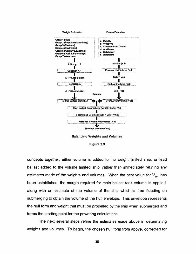
3.1 PROPULSION INTEGRATION
Table 3.1 presents a summary of possible propulsion options to be
considered in this study.
TABLE 3.1
Propulsion Options
Propulsion Type Attributes Technology StatusConventional DC 220 - 880 VDC Mature, proven at-sea
service for many yearsPermanent Magnet AC 800 VAC, Variable Near maturity, foreign
Frequency shipboard installationsplanned
Superconducting 100 - 200 VDC ImmatureHomopolar DC 100 - 200 kAMPS
3.1.1 CONVENTIONAL DC
Advantages Disadvantages
-Reliable Technology -Large WeightNolume-Compatibility with Battery Systems
The most common arrangement in service is the conventional DC motor
from a high voltage (220 - 880 VDC) bus, which until recently was the only viable
technology available. Double armature motors with creative battery switching
38

Basic Circuit Mode I
L HA'- {RlI M )
IHiK) ( M1
i II
L I I
Mode 2 Mode 3 Mode 4 Mode 5
Battery Stepping Operating Modes for a Double Armature DC Motor [27]
Figure 3.1
schemes such as Figure 3.1 gives the operator flexibility in terms of speed
control and system configuration. Based on its vast historical operating
experience, this concept is well proven in terms of reliability. While
improvements have been made, these machines are heavy and volumous when
compared to AC machines of similar power output. Their widespread use
however is a result of their excellent low speed torque characteristics and their
ready compatibility to the varying DC voltage characteristics of the traditional
Lead-Acid battery based electrical distribution system.
39
ii_
--
7 :f:
i
Il: ..r
Lc
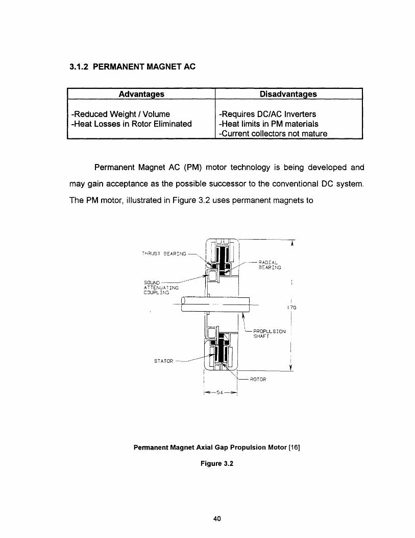
3.1.2 PERMANENT MAGNET AC
Permanent Magnet AC (PM) motor technology is being developed and
may gain acceptance as the possible successor to the conventional DC system.
The PM motor, illustrated in Figure 3.2 uses permanent magnets to
Permanent Magnet Axial Gap Propulsion Motor [16]
Figure 3.2
40
Advantages Disadvantages
-Reduced Weight / Volume -Requires DC/AC Inverters-Heat Losses in Rotor Eliminated -Heat limits in PM materials
-Current collectors not mature
7
D
replace the magnetic field source on the rotor eliminating significant amounts of
electrical wiring. In this design the rotor, and stator are disc shaped vice a
conventional can shaped stator encircling the rotor core. With the disc
geometry, a larger number of poles can be included, with smaller end turn
volumes and reduced stator back iron size and weight, giving the motor a higher
degree of speed control. Estimates of the weight and volume savings for PM
motors over comparable DC motors are on the order of 50 and 40 percent,
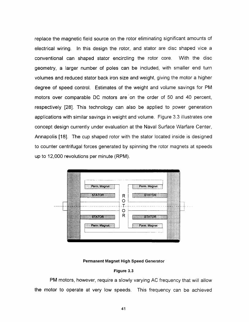
respectively [28]. This technology can also be applied to power generation
applications with similar savings in weight and volume. Figure 3.3 illustrates one
concept design currently under evaluation at the Naval Surface Warfare Center,
Annapolis [18]. The cup shaped rotor with the stator located inside is designed
to counter centrifugal forces generated by spinning the rotor magnets at speeds
up to 12,000 revolutions per minute (RPM).
~ .~. .:'~.' I ............~~~~~~~~~~~~~~~~~~~~~~~~~~~~~~~~~~~~~. . . . .. .2·22. ~ Mane
i~''3 ATi~ j~~.~iiiiii~I·I Mzt
RO
.. T-.
OR
Permanent Magnet High Speed Generator
Figure 3.3
PM motors, however, require a slowly varying AC frequency that will allow
the motor to operate at very low speeds. This frequency can be achieved
41
...............:::::.... .... ....·:·:iiiii~~~iiiiiiiiii~~~~~i~. ~ ~ ~ ~ % .......................
:i~~~~~~~j::j........C:~:ii:·::~:::j:::::::::.~I............
... . .. ...... ·::·: ·"WAT~~~~~~~~~~~':"i~:r'''........... .... ... .............. ;:;2. ............iiii a...............::::~~:::::::~~::::i:~~~::.. .. .....
X ... .........'j~............ .. ........~::ll~li......... . ....:: · ·:: · · :: · ·:·. :··

through the use of power electronics to chop a DC input signal to provide an
output AC voltage of the appropriate frequency, Figure 3.4. Alternately, this AC
voltage can be created by using a DC motor - AC generator set, varying the
speed by control of the DC motor field.
00
Input DC Voltage Output AC Voltage
Example of Chopped AC Output From Input DC
Figure 3.4
3.1.3 SUPERCONDUCTING HOMOPOLAR DC
While still an immature technology in its final form, the Superconducting
Homopolar (SC) motor is a next generation of propulsion technology, taking
advantage of "zero" resistance properties of electrical conductors when they
have been cooled to near zero degree Kelvin conditions. The SC motor
illustrated in Figure 3.5 is currently under development at the Naval Surface
42
Advantages Disadvantages
-Reduced Weight / Volume -Requires Cryogenic Cooling-Reduced Noise / Direct Mounting to -High electrical currentshull -Current collectors not fully developed
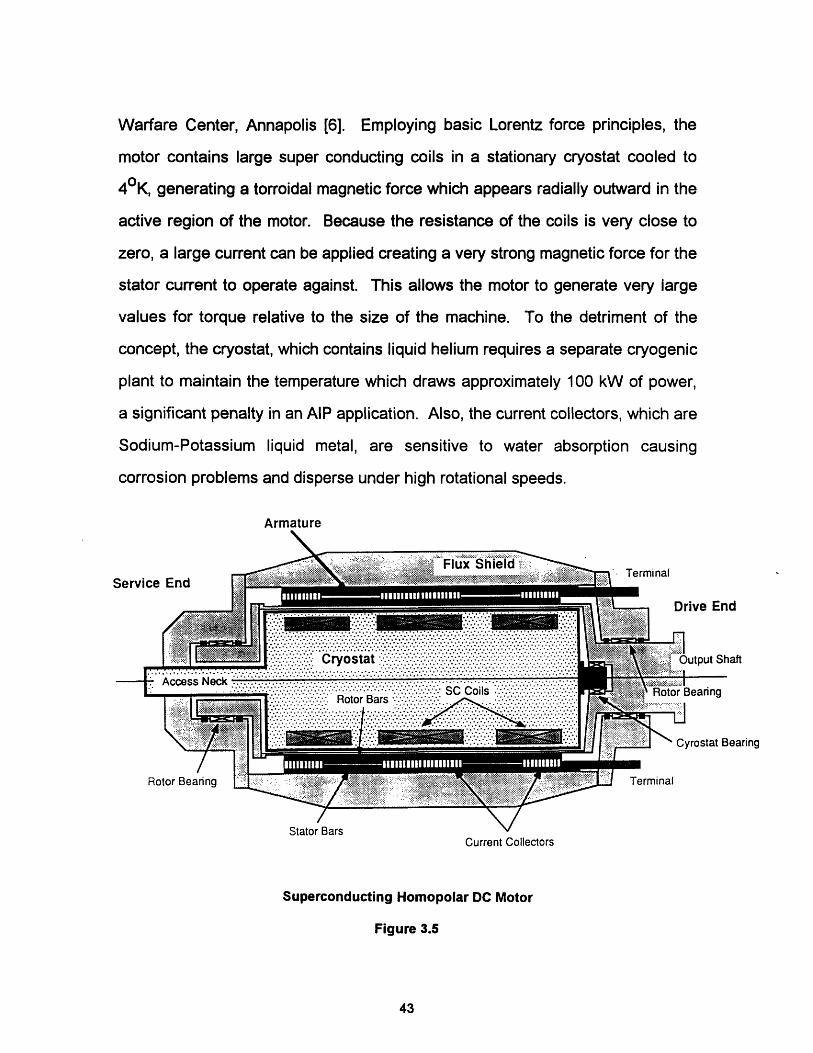
Warfare Center, Annapolis [6]. Employing basic Lorentz force principles, the
motor contains large super conducting coils in a stationary cryostat cooled to
40K, generating a torroidal magnetic force which appears radially outward in the
active region of the motor. Because the resistance of the coils is very close to
zero, a large current can be applied creating a very strong magnetic force for the
stator current to operate against. This allows the motor to generate very large
values for torque relative to the size of the machine. To the detriment of the
concept, the cryostat, which contains liquid helium requires a separate cryogenic
plant to maintain the temperature which draws approximately 100 kW of power,
a significant penalty in an AIP application. Also, the current collectors, which are
Sodium-Potassium liquid metal, are sensitive to water absorption causing
corrosion problems and disperse under high rotational speeds.
Armature
Stator Bars VCurrent Collectors
Superconducting Homopolar DC Motor
Figure 3.5
43

3.1.4 PROPULSORS
The standard submarine propulsor is of fixed pitch design, specially
designed to minimize the effects of cavitation while submerged. Other styles of
propulsors, such as contra-rotating (CR) or ducted propellers have been
proposed and installed on submarines, but problems of one type or another have
kept them from gaining acceptance. The CR propeller offers a 10 percent
increase in the propulsive coefficient for a submarine application [12].
Historically, the problem with a contra rotating system has been the transmission
of power through some form of reduction gear to the propulsion shaft. The
emergence of PM and SC technology, with its compact design, offers a good
solution to this dilemma [19].
3.2 SHIP SERVICE POWER REQUIREMENTS
While the propulsion load will vary constantly, the ship service or hotel
load of the submarine will remain fairly constant for a given operating profile.
Included in this hotel load are the minimum power requirements for ship control
and operation and atmosphere control. These loads can be expected to vary for
each operating profile of the ship, such as a battle station condition when all
crew members are on station and most systems are operating, to an ultra quiet
condition when most crew members are retired and only a minimum number of
systems are operating.
Most equipment is operated by some form of electricity from a ship
service bus. Conventional submarines generally employ ship service busses
that are DC power based because of their link to the storage battery, thus any
load that cannot operate off a DC voltage source that varies with the state of
charge on the battery must be converted. Motor generator sets or static power
inverters are utilized to convert DC power to its required form, such as:
44
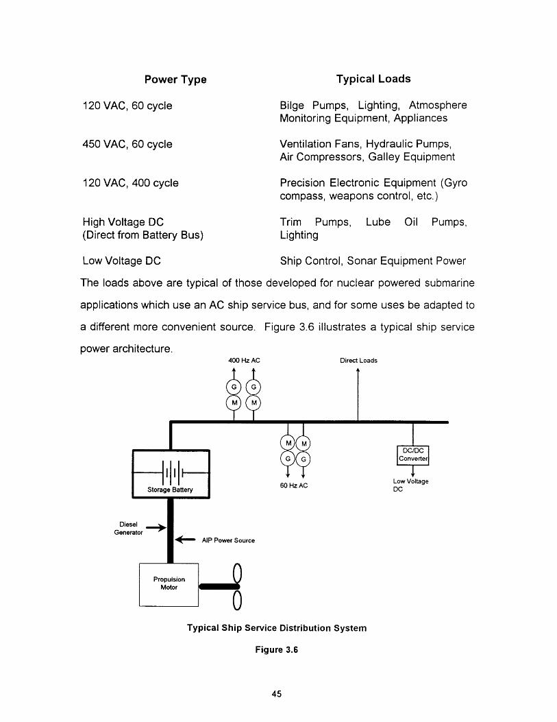
Typical Loads
120 VAC, 60 cycle
450 VAC, 60 cycle
Bilge Pumps, Lighting, AtmosphereMonitoring Equipment, Appliances
Ventilation Fans, Hydraulic Pumps,Air Compressors, Galley Equipment
120 VAC, 400 cycle Precision Electronic Equipment (Gyrocompass, weapons control, etc.)
High Voltage DC Trim Pumps, Lube Oil Pumps,(Direct from Battery Bus) Lighting
Low Voltage DC Ship Control, Sonar Equipment Power
The loads above are typical of those developed for nuclear powered submarine
applications which use an AC ship service bus, and for some uses be adapted to
a different more convenient source. Figure 3.6 illustrates a typical ship service
power architecture.400 Hz AC Direct Loads
60 Hz AC
DiesGenei
DC
4' AIP Power Source
Typical Ship Service Distribution System
Figure 3.6
45
Power Type

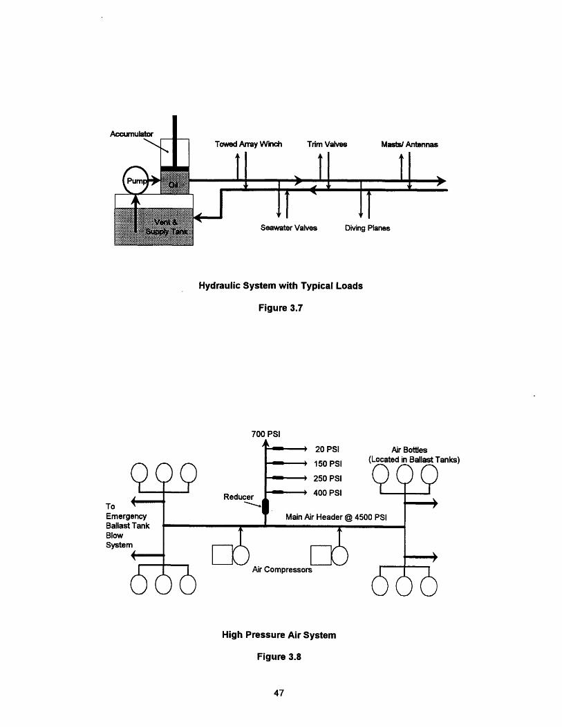
3.3 AUXILIARY SYSTEMS
The electrical distribution network is but one small part of the vital
submarine support network. A fully integrated system of pneumatic and
hydraulic controls and operators supplements the ship operations, providing
compact, high powered operating mechanisms for large equipment such as
diving planes, masts and antennas and seawater valves. Most systems are
comprised of a central power plant where the energy of that system is created,
then distributed to various operating points or to storage locations. For example,
a typical hydraulic system features a storage tank, pump and high pressure
accumulator all in one package which then feeds a hydraulic distribution system,
Figure 3.7. A typical pneumatic system features air compressors connected to a
high pressure air header, which feeds high pressure air storage bottles and a
distributed network of lower pressure air systems, Figure 3.8. Here the air
storage bottles are spread throughout the ship, typically in the vicinity of the
main ballast tanks to provide an immediate emergency source of surfacing air.
These types of systems are important supplements to the electrical network
because of their simplicity in operation, their reliability in the face of a propulsion
plant casualty, and the energy density available in the high pressure fluids they
contain.
3.4 ATMOSPHERE CONTROL
A vital distributed auxiliary system, but one which seems far less defined
is the ventilation / atmosphere control system. This system comprises the
necessary fans and ductwork to bring air into the ship, recirculate it when
submerged and purify it so that the air continues to be breathable. All
submarines have similar arrangements, however AIP variants must contend with
the additional concern of air revitalization, that is the removal of contaminants
46
Towed Array Winch
Seawater Valves Diving Planes
Hydraulic System with Typical Loads
Figure 3.7
700 PSI
20 PSI
150 PSI
250 PSI
400 PSI
Main Air Header
Air Bottles(Located in Ballast Tanks)000
@ 450)0 PSI
Air Compressors
r
, v0
(00
High Pressure Air System
Figure 3.8
47
ReduceToEmergencyBallast TankBlowSystem
,A
Trim Valves Masts/ Antennas
oh
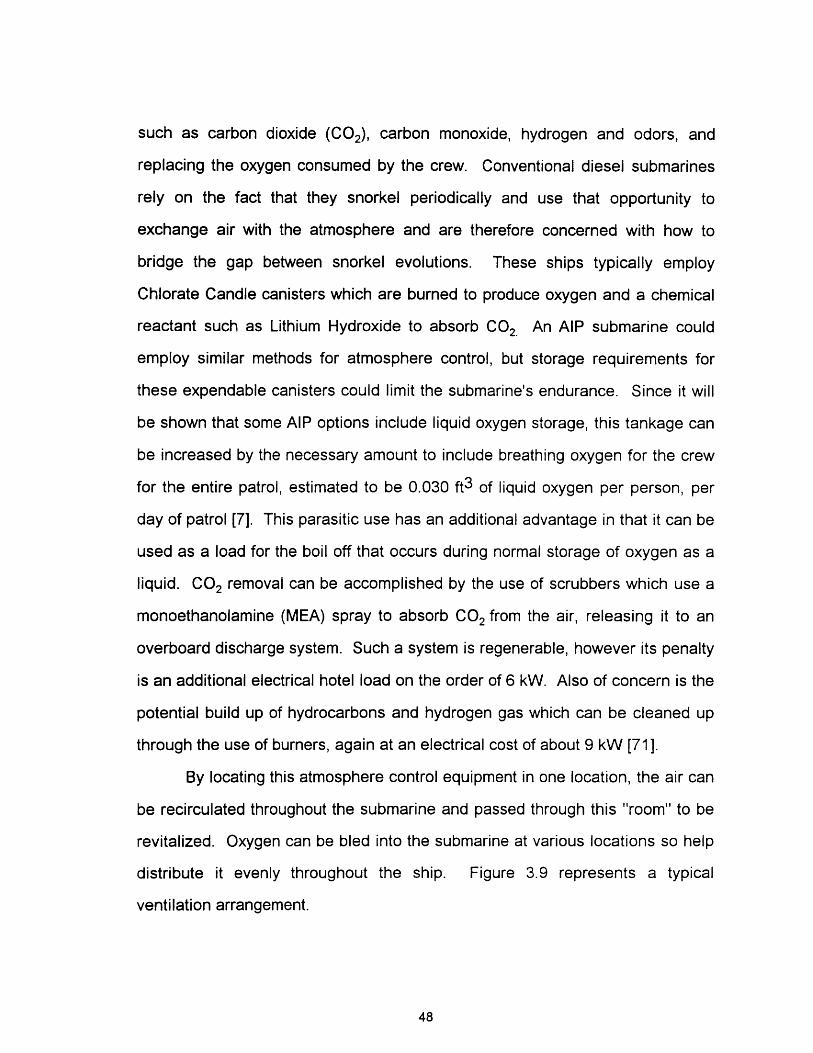
such as carbon dioxide (CO2), carbon monoxide, hydrogen and odors, and
replacing the oxygen consumed by the crew. Conventional diesel submarines
rely on the fact that they snorkel periodically and use that opportunity to
exchange air with the atmosphere and are therefore concerned with how to
bridge the gap between snorkel evolutions. These ships typically employ
Chlorate Candle canisters which are burned to produce oxygen and a chemical
reactant such as Lithium Hydroxide to absorb CO2 An AIP submarine could
employ similar methods for atmosphere control, but storage requirements for
these expendable canisters could limit the submarine's endurance. Since it will
be shown that some AIP options include liquid oxygen storage, this tankage can
be increased by the necessary amount to include breathing oxygen for the crew
for the entire patrol, estimated to be 0.030 ft3 of liquid oxygen per person, per
day of patrol [7]. This parasitic use has an additional advantage in that it can be
used as a load for the boil off that occurs during normal storage of oxygen as a
liquid. CO2 removal can be accomplished by the use of scrubbers which use a
monoethanolamine (MEA) spray to absorb CO2 from the air, releasing it to an
overboard discharge system. Such a system is regenerable, however its penalty
is an additional electrical hotel load on the order of 6 kW. Also of concern is the
potential build up of hydrocarbons and hydrogen gas which can be cleaned up
through the use of burners, again at an electrical cost of about 9 kW [71].
By locating this atmosphere control equipment in one location, the air can
be recirculated throughout the submarine and passed through this "room" to be
revitalized. Oxygen can be bled into the submarine at various locations so help
distribute it evenly throughout the ship. Figure 3.9 represents a typical
ventilation arrangement.
48
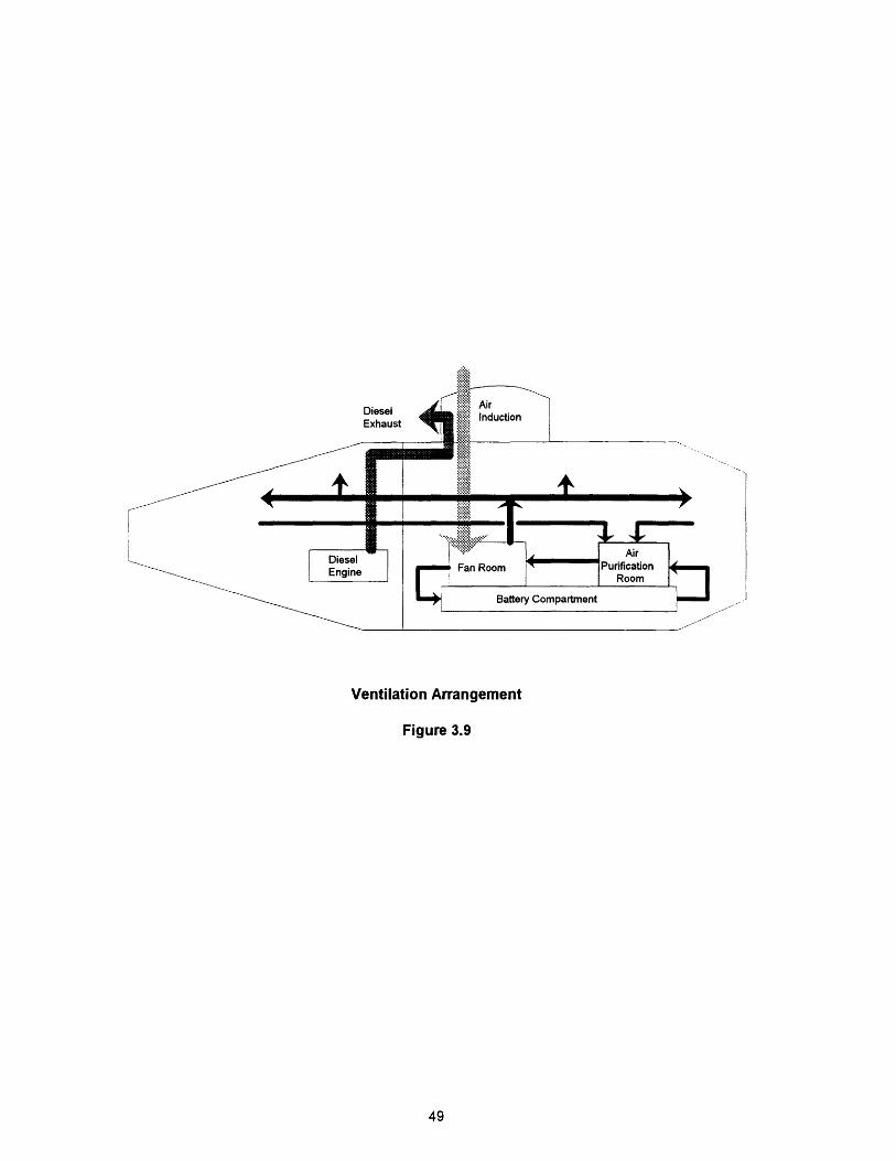
Ventilation Arrangement
Figure 3.9
49

(Blank Reverse)
50
CHAPTER FOUR
4.0 POWER SOURCES
Many AlP power plants have been proposed, with development
conducted by those countries that have a genuine interest in promoting air
independence for their own submarines or for the commercial submarine market.
This chapter investigates current and proposed power source options.
An AIP power plant is composed of several parts combined into one
functional system. These parts are:
- Energy conversion device
- Fuel source
- Oxidant source
- Waste product management.
Reactants, which include fuels and oxidants, and waste product management,
which can involve the storage of pure water or discharging high volumes of
carbon dioxide overboard will be examined in Chapter 5.
The energy conversion device can be categorized as either electro-
chemical or mechanical, depending on how the energy conversion is performed.
Mechanical AIP concepts include compact heat engines modified to run in the
absence of a normal atmosphere such as the closed cycle diesel, to entire
cycles, such as a Rankine cycle whose heat source is a simple combustor
burning hydrogen and oxygen. A discussion of these plants can be found in
Section 4.2. Electro-chemical concepts include a range of fuel cell and high
performance primary and secondary battery options and will be discussed first.
51
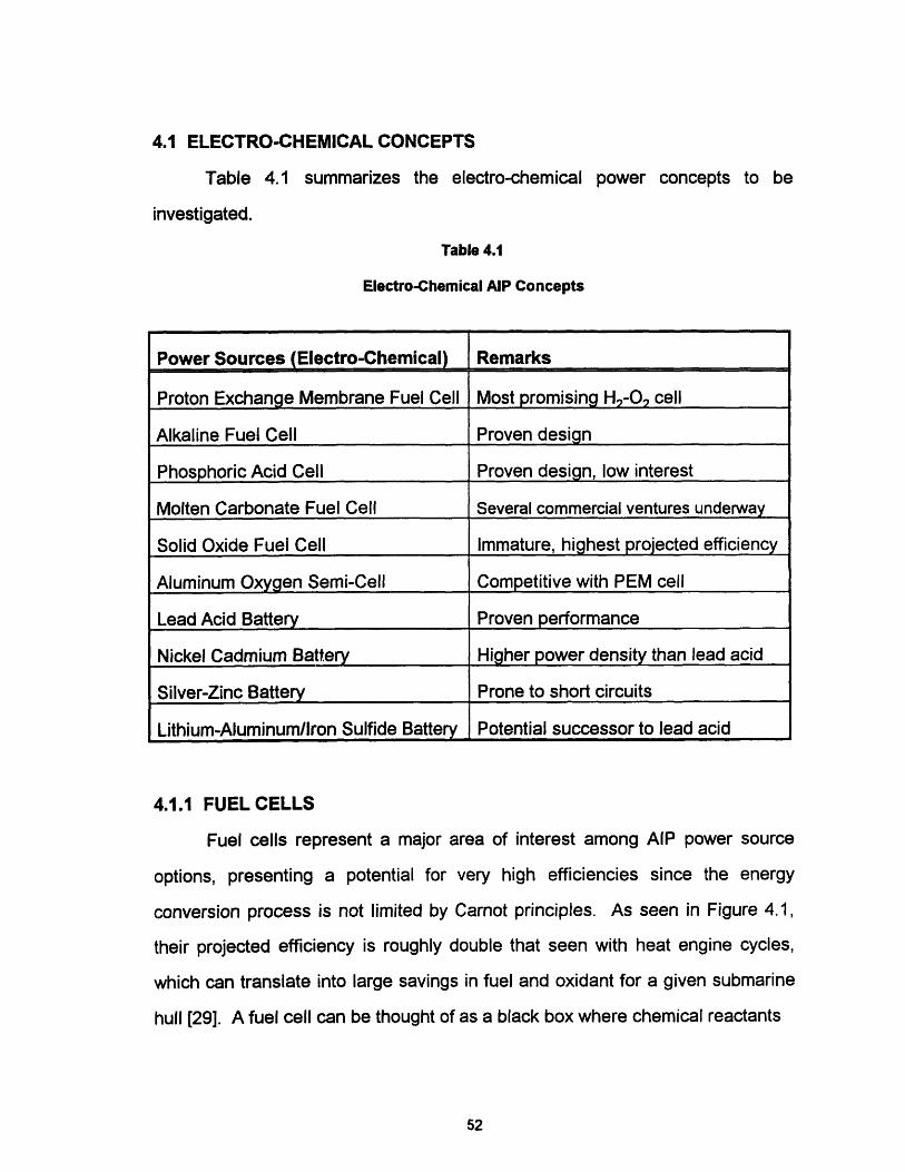
4.1 ELECTRO-CHEMICAL CONCEPTS
Table 4.1 summarizes the electro-chemical power concepts to be
investigated.
Table 4.1
Electro-Chemical AIP Concepts
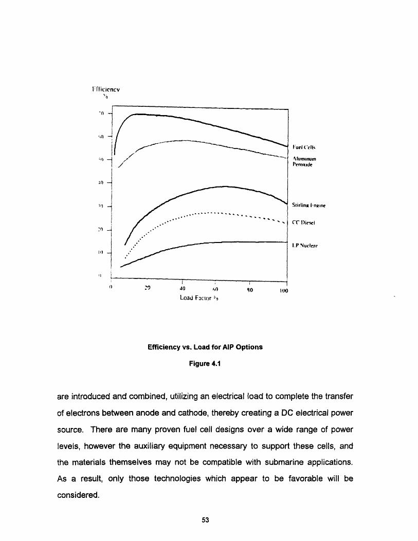
4.1.1 FUEL CELLS
Fuel cells represent a major area of interest among AIP power source
options, presenting a potential for very high efficiencies since the energy
conversion process is not limited by Carnot principles. As seen in Figure 4.1,
their projected efficiency is roughly double that seen with heat engine cycles,
which can translate into large savings in fuel and oxidant for a given submarine
hull [29]. A fuel cell can be thought of as a black box where chemical reactants
52
Power Sources (Electro-Chemical) Remarks
Proton Exchange Membrane Fuel Cell Most promising H.-O. cell
Alkaline Fuel Cell Proven design
Phosphoric Acid Cell Proven design, low interest
Molten Carbonate Fuel Cell Several commercial ventures underway
Solid Oxide Fuel Cell Immature, highest projected efficiency
Aluminum Oxygen Semi-Cell Competitive with PEM cell
Lead Acid Battery Proven performance
Nickel Cadmium Battery Higher power density than lead acid
Silver-Zinc Battery Prone to short circuits
Lithium-Aluminum/lron Sulfide Battery Potential successor to lead acid
i flicicncvi)
'I)
V)In
In
IFuel (cal
AluminumPeroxide
Stirlina inRmeC
CC 1)ie.cl
I.P Nuclear
Jo40 6( 90 1 00
ltoad Factor o
Efficiency vs. Load for AIP Options
Figure 4.1
are introduced and combined, utilizing an electrical load to complete the transfer
of electrons between anode and cathode, thereby creating a DC electrical power
source. There are many proven fuel cell designs over a wide range of power
levels, however the auxiliary equipment necessary to support these cells, and
the materials themselves may not be compatible with submarine applications.
As a result, only those technologies which appear to be favorable will be
considered.
53
4.1.1.1 PROTON EXCHANGE MEMBRANE FUEL CELL
The Proton Exchange Membrane (PEM) cell is presently the most popular
fuel cell in terms of interest and development for submarine applications. This
thought is underscored by German industry, which after successfully
demonstrating a small alkaline fuel cell plant in a Type 205 submarine in 1987,
has abandoned that variety of cell in favor of the PEM cell [29]. The PEM cell is
also being studied as a part of AIP development programs in the United
Kingdom, Canada and Australia. In addition, the US Navy has developed PEM
technology for replacement of alkaline cell technology in the oxygen generating
equipment found onboard its nuclear submarines [55].
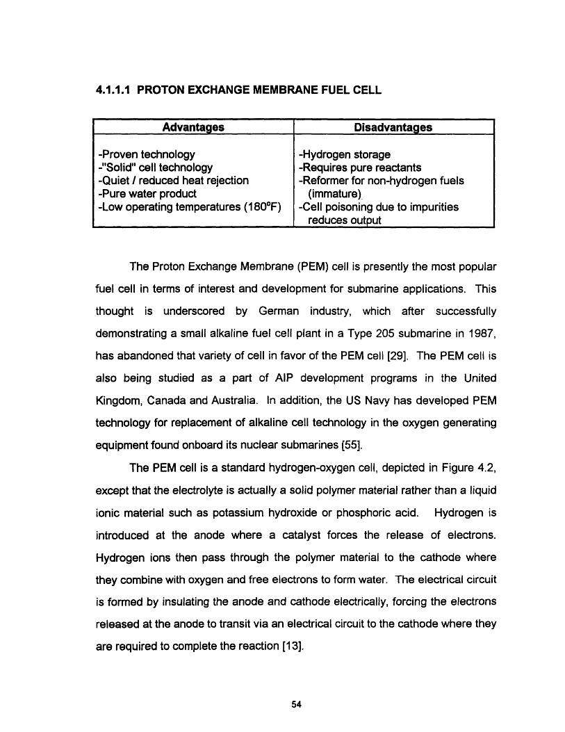
The PEM cell is a standard hydrogen-oxygen cell, depicted in Figure 4.2,
except that the electrolyte is actually a solid polymer material rather than a liquid
ionic material such as potassium hydroxide or phosphoric acid. Hydrogen is
introduced at the anode where a catalyst forces the release of electrons.
Hydrogen ions then pass through the polymer material to the cathode where
they combine with oxygen and free electrons to form water. The electrical circuit
is formed by insulating the anode and cathode electrically, forcing the electrons
released at the anode to transit via an electrical circuit to the cathode where they
are required to complete the reaction [13].
54
Advantages Disadvantages
-Proven technology -Hydrogen storage-"Solid" cell technology -Requires pure reactants-Quiet / reduced heat rejection -Reformer for non-hydrogen fuels-Pure water product (immature)-Low operating temperatures (1 80F) -Cell poisoning due to impurities
reduces output
- Hydrogen
Water
Overall Cell Reaction: H2+ O2 -- H202
Proton Exchange Membrane Fuel Cell [39]
Figure 4.2
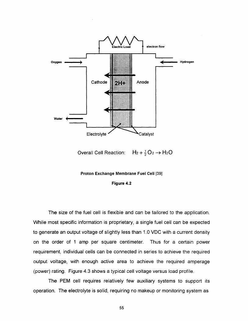
The size of the fuel cell is flexible and can be tailored to the application.
While most specific information is proprietary, a single fuel cell can be expected
to generate an output voltage of slightly less than 1.0 VDC with a current density
on the order of 1 amp per square centimeter. Thus for a certain power
requirement, individual cells can be connected in series to achieve the required
output voltage, with enough active area to achieve the required amperage
(power) rating. Figure 4.3 shows a typical cell voltage versus load profile.
The PEM cell requires relatively few auxiliary systems to support its
operation. The electrolyte is solid, requiring no makeup or monitoring system as
55
Oxygen

1
0.9_ 0.8p 0.7
0.61 0.5o' 0.4= 0.3
L 0.2
0.1
00 0.5 1 1.5 2
Current Density (Amps/cm2)
PEM Cell Voltage versus Cell Load [74]
Figure 4.3
in liquid electrolyte designs, greatly improving its simplicity. The cell is classified
as low temperature in comparison to other systems. With an operating
temperature around 2000 F, the time required for the cell to reach operating
temperature is relatively short, making it ideal for rapid start-up, an important
operating characteristic. The lower operating temperature is also more
compatible with an enclosed submarine environment [44]. The only product
discharge from the cell is pure water, which is potable and easily handled, either
by storage for crew consumption or transfer to a variable ballast system for
discharge overboard. A significant issue for the PEM cell is the fuel source.
The solid polymer electrolyte membrane is susceptible to contamination by
impurities in the fuel gas, specifically carbon monoxide, a by-product of the
reformation process. While carbon monoxide contamination does not
permanently damage the cell, concentrations as high as 10 PPM can
56

dramatically affect cell performance, requiring regeneration of the cell with a
clean gas source [3]. Development of a "clean" reformer is a significant
developmental issue and is discussed further in Section 5.1.1.3.
Specific details on the PEM cell can be found in Appendix A.
4.1.1.2 ALKALINE FUEL CELL
This fuel cell is very similar in concept to the PEM cell with exception of
the electrolyte and its added complexities, and has been demonstrated to
operate successfully at sea in a German Type 205 submarine. This system
used potassium hydroxide to conduct the hydrogen ions to the cathode for
recombination [55]. Figure 4.2 presented earlier for the PEM cell applies to the
alkaline cell as well.
4.1.1.3 PHOSPHORIC ACID FUEL CELLS
57
Advantages Disadvantages
-Demonstrated performance "at-sea" -Hydrogen storage-Quiet / reduced heat rejection -Liquid electrolyte / more complex-Pure water product than PEM-Low operating temperatures (1 800F) -Requires pure reactants
-Reformer for non-hydrogen fuels(immature)
Advantages Disadvantages
-Demonstrated commercial -High operating temperatures (4000 F)performance -Liquid electrolyte / more complex
-Quiet / reduced heat rejection than PEM-Pure water product -Larger / heavier than PEM, same-Can reform hydrogen fuels internally efficiency
Another variant of the basic hydrogen oxygen fuel cell is the Phosphoric
Acid Fuel Cell (PAFC), which is conceptually similar to the alkaline cell. using
phosphoric acid as an electrolyte. While this cell is fueled by pure hydrogen,
variants operated at higher temperatures (4000F) may be able to reform
hydrogen based fuels internally as this cell is not susceptible to carbon
monoxide poisoning [21]. Commercial development of the PAFC as a "portable"
remote power source fueled with natural gas is mature. At issue for submarine
applications are the significantly larger volumes and weights for similar efficiency
when compared to PEM technology and lower efficiency when compared to
other similar sized high temperature cells to be discussed [65].
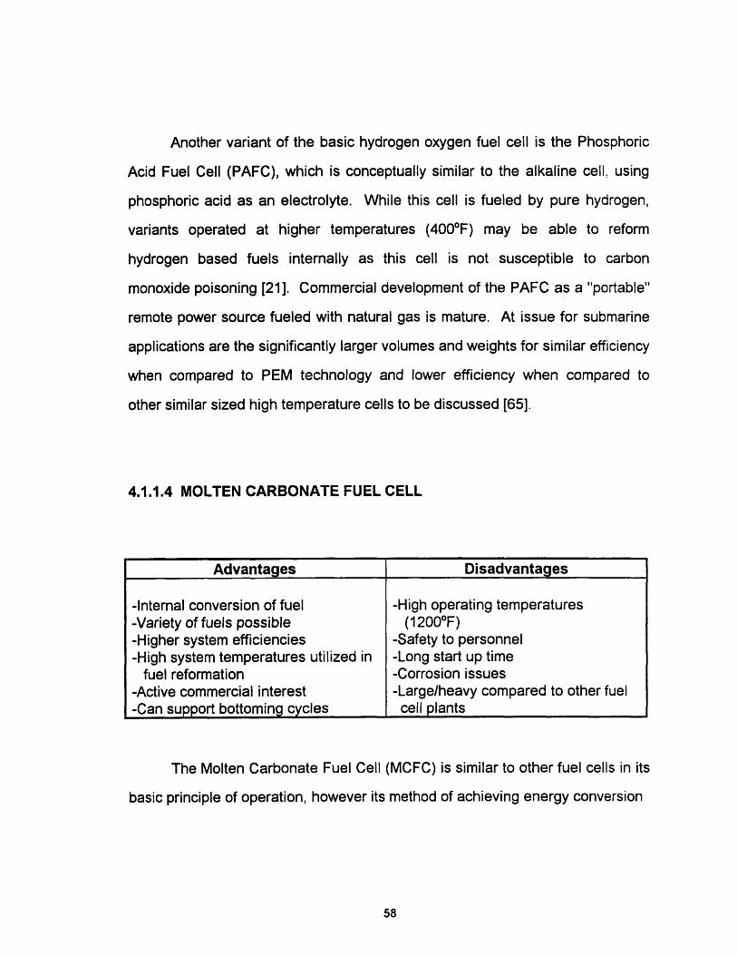
4.1.1.4 MOLTEN CARBONATE FUEL CELL
The Molten Carbonate Fuel Cell (MCFC) is similar to other fuel cells in its
basic principle of operation, however its method of achieving energy conversion
58
Advantages Disadvantages
-Internal conversion of fuel -High operating temperatures-Variety of fuels possible (12000F)-Higher system efficiencies -Safety to personnel-High system temperatures utilized in -Long start up time
fuel reformation -Corrosion issues-Active commercial interest -Large/heavy compared to other fuel-Can support bottoming cycles cell plants
is quite different. Illustrated in Figure 4.4, the MCFC utilizes a molten carbonate
salt as the electrolyte, and thus must be heated to around 1200F to function. If
properly insulated, this high heat can be used to internally reform any number of
hydrogen based fuels, such as marine diesel or methanol, making this option
especially attractive. Similar to the PEM cell, pure water is produced as a result
of the reaction, however other products, such as carbon dioxide are produced as
well. The relative volume of carbon dioxide gas produced depends on the type
of fuel used in the cell. Because of the high temperature of the cell, the waste
heat from the cell can be used to operate some form of bottoming cycle,
improving overall system efficiency [65].
Appendix A contains more specific data on MCFC
HydrogenFuel IN -
C02OUT
WaterOUT 4
OxygenIN
CO2IN
Reaction on Cathode Surface: ½02 + C02 + 2e- CO3=
Reaction on Anode Surface: H2 + C03= - C02 + H20 + 2e-
Molten Carbonate Fuel Cell
Figure 4.4
59

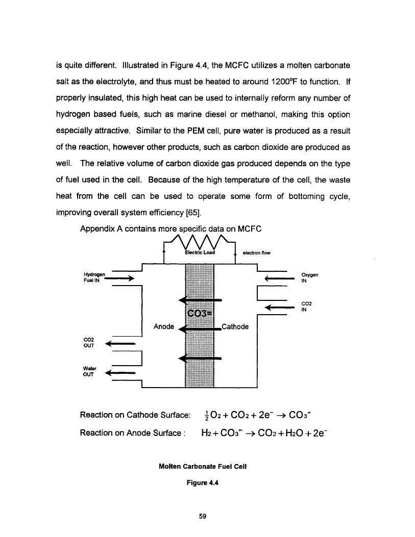
4.1.1.5 SOLID OXIDE FUEL CELL
The Solid Oxide Fuel Cell (SOFC) is a new, advanced technology which
is still very immature. Similar to the MCFC, it operates at high temperature
(18000F) and can therefore internally reform various types of fuel. Its electrolyte
however is a solid, nonporous metal oxide, eliminating the need for a liquid
electrolyte management system. The higher operating temperature of the SOFC
promises that it should enjoy a higher efficiency than the MCFC, and projections
are that SOFC technology should be very weight and volume efficient [65]. One
design by Westinghouse for possible shipboard applications is shown in Figure
4.5. Here an oxidant is passed inside a cylindrical cell with the fuel gas passed
on the outside. Similar to other fuel cell applications, the ceramic metal oxide
passes oxygen ions through to the cathode where they combine with hydrogen
and carbon monoxide to form carbon dioxide and water.
4.1.1.6 DIRECT METHANOL OXIDATION FUEL CELL
This cell represents research in PEM technology aimed at eliminating the
reformer requirement when using fuels other than pure hydrogen. It is very
immature and is not formally evaluated in this study.
60
Advantages Disadvantages
-Internal conversion of fuel -Immature technology-Variety of fuels possible -High operating temperatures-Highest system efficiency (projected) (1 8000 F)-High system temperatures utilized in -Safety to personnel
fuel reformation -Long start up time-Can support bottoming cycles
The cell operates at low temperature and contains the solid polymer
electrolyte. The difference is a special catalyst at the anode which transforms
methanol fuel into hydrogen and carbon dioxide, a gas with no effect on cell
efficiency. Present cell performance has an output voltage of 0.6 VDC (slightly
less than PEM) at a current density of 0.1 Amps/cm2 (1/10th of the PEM cell)
[37].
ElectroAirElectrod
Air /Flow
Reaction on Anode Surface:
Reactions on Cathode Surface:
02 + 4e- --> 20=
2H2 + 20 -> 2H20 + 4e-
2CO + 20 - 2C02 + 4e-
Westinghouse Solid Oxide Fuel Cell [5]
Figure 4.5
61
I U 911L V V

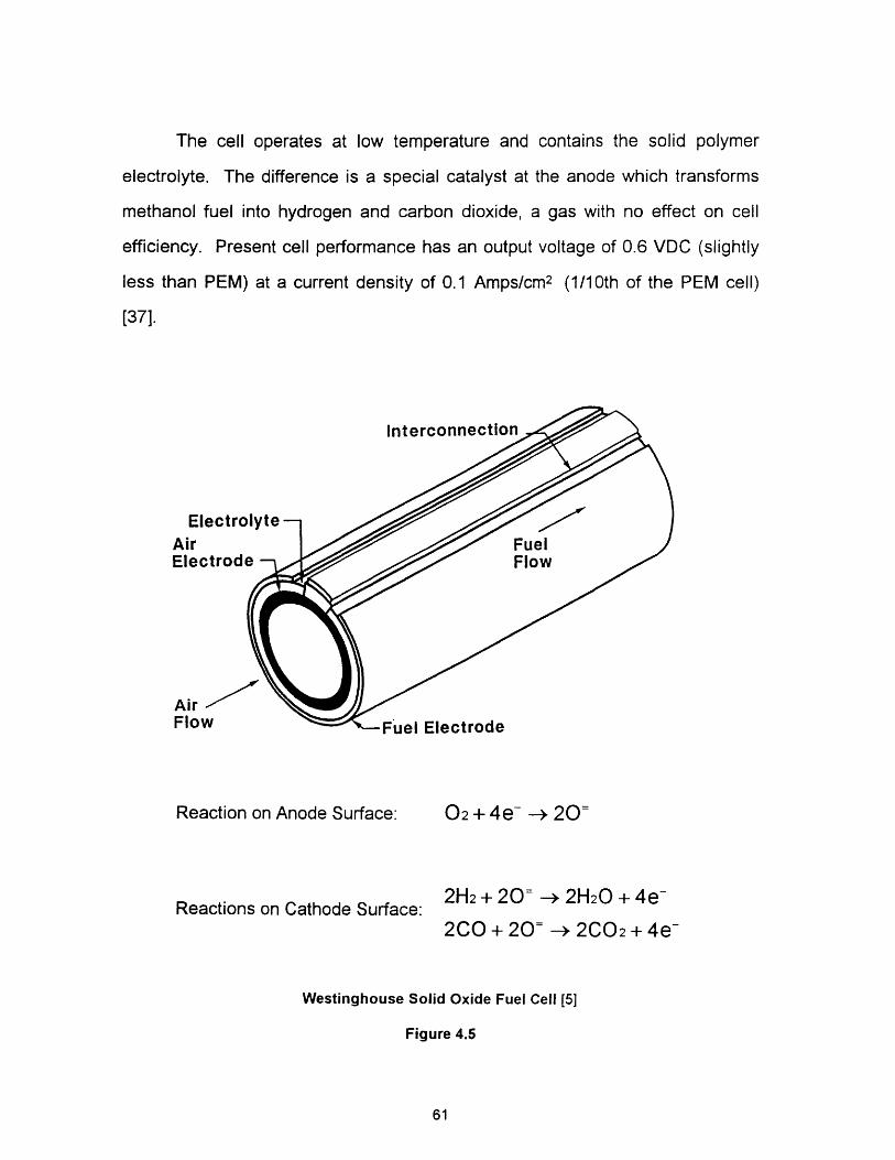
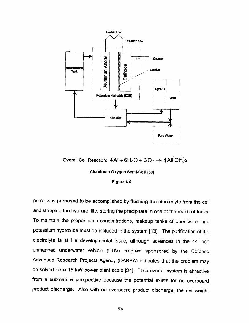
4.1.2 ALUMINUM OXYGEN SEMI-CELL
The Aluminum Oxygen Semi-Cell (aluminum) is categorized separately
from other fuel cells because although it relies on a chemical reaction to free
electrons for electrical power output, its fuel source is actually the cathodic
aluminum plate contained within the cell, Figure 4.6. Conceptually there are
three variants of the aluminum cell, each utilizing a different form of oxidant.
First is the use of pure oxygen, which is currently under development in Canada
for submarine applications and in the United States and Canada for autonomous
underwater vehicle (AUV) applications. A second variant uses air as the oxidant
and is really a modification to the first. A third variant suggests the use of
hydrogen peroxide (H202) for the oxidant. While unstable in high
concentrations, this idea has merit because H202 provides not only oxygen but
also water, a reactant that the cell needs in large quantity.
In the cell pictured in Figure 4.6, a complete system was included to show
one of the detriments of the aluminum cell. In this cell, the aluminum anode is
literally corroded away to form a product called hydrargillite {AI(OH)3}. This
product must be constantly removed otherwise it will reduce the conductivity of
the electrolyte to the point where the cell will no longer function. This removal
62
Advantages Disadvantages
-No hydrogen required -Expensive fuel-No products discharged/net weight -Frequent cell replacement
unchanged with time -Hydrargillite management-Requires one half the oxygen of -High cell weight
other comparably sized fuel cells -Caustic electrolyte-High density fuel source
Elecric Load
Pure Water
i I
Overall Cell Reaction: 4AI + 6H20 + 302 -* 4AI(OH)3
Aluminum Oxygen Semi-Cell [39]
Figure 4.6
process is proposed to be accomplished by flushing the electrolyte from the cell
and stripping the hydrargillite, storing the precipitate in one of the reactant tanks.
To maintain the proper ionic concentrations, makeup tanks of pure water and
potassium hydroxide must be included in the system [13]. The purification of the
electrolyte is still a developmental issue, although advances in the 44 inch
unmanned underwater vehicle (UUV) program sponsored by the Defense
Advanced Research Projects Agency (DARPA) indicates that the problem may
be solved on a 15 kW power plant scale [24]. This overall system is attractive
from a submarine perspective because the potential exists for no overboard
product discharge. Also with no overboard product discharge, the net weight
63

change of mobility for the plant is theoretically zero, with only the weight
distribution changing.
The electrolyte described here is the option currently under development
in Canada, but other alkaline (sodium hydroxide) or saline solutions (seawater)
could be used. The concept that envisioned the use of H202 as an oxidant was
actually in combination with seawater. AIP studies conducted in Canada have
concluded that aside from the hazards of handling H2 02, the most efficient
oxidant option for large submarines is oxygen in liquid form [39].
4.1.3 BATTERIES
Batteries fall into two categories, Primary and Secondary. Primary
batteries are just that, a primary power source for an application. They are not
rechargeable and would be appropriate for one time applications where it is
important to keep costs down, i.e. not for frequent replacement over the thirty
year life of a ship. Secondary batteries, such as the common lead acid battery,
are rechargeable, and have been used successfully in submarines for many
years. The battery is a temporary energy storage source intended to provide
submerged power for diesel submarines and emergency power in nuclear
submarines. Only secondary batteries will be considered in this thesis.
Table 4.2 presents a summary of current and near term secondary
batteries. Those technologies which are mature or have immediate promise will
be discussed here.
64
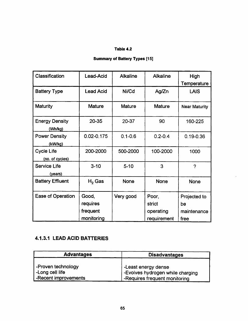
Table 4.2
Summary of Battery Types [15]
Classification Lead-Acid Alkaline Alkaline High
Temperature
Battery Type Lead Acid Ni/Cd Ag/Zn LAIS
Maturity Mature Mature Mature Near Maturity
Energy Density 20-35 20-37 90 160-225
(Wh/kg)
Power Density 0.02-0.175 0.1-0.6 0.2-0.4 0.19-0.36
(kW/kg)
Cycle Life 200-2000 500-2000 100-2000 1000
(no. of cycles)
Service Life 3-10 5-10 3 ?
(years)
Battery Effluent H2 Gas None None None
Ease of Operation Good, Very good Poor, Projected to
requires strict be
frequent operating maintenance
monitoring requirement free
4.1.3.1 LEAD ACID BATTERIES
Advantages Disadvantages
-Proven technology -Least energy dense-Long cell life -Evolves hydrogen while charging-Recent improvements -Requires frequent monitoring
65
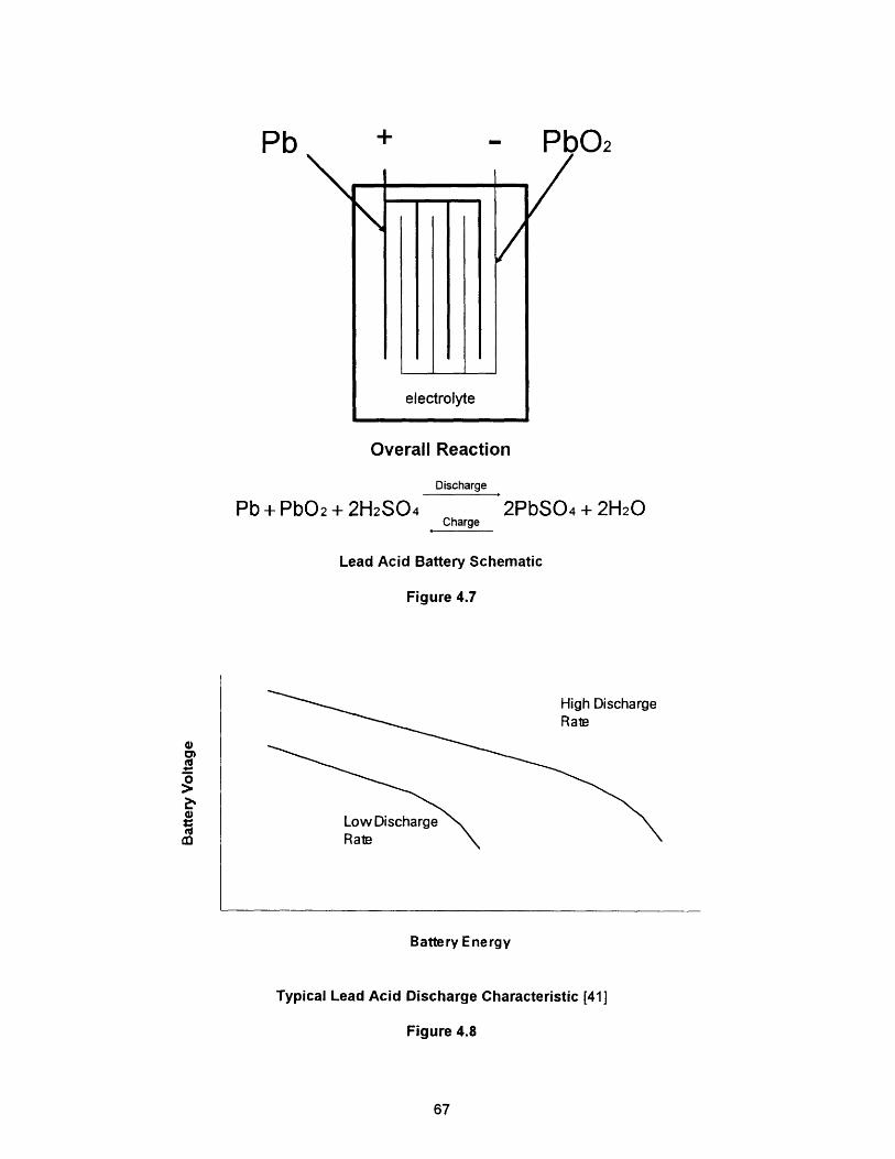
By far, the most common battery type in use is the lead acid battery,
shown in Figure 4.7. A single cell consists of a series of negative and positive
plates, made of lead and lead dioxide respectively, immersed in a sulfuric acid
electrolyte and sealed in a rubber jar. Charging and discharging of the cells
transfers electrons back and forth between the plates and the electrolyte. The
cell voltage is nominally 2 VDC and any number of cells can be connected in
series or parallel to provide the required output voltage for the battery group.
Connected directly to a DC distribution bus, the instantaneous voltage can be
expected to decrease as much as 20 percent depending on the state of charge
of the battery 63]. While the basic cell hasn't changed with time, the addition of
certain metals to the active cell matrix have significantly improved battery
performance [42].
Because the chemical reaction can proceed in both directions, the
battery's ability to deliver and receive a total amount of energy depends on the
rate of the reaction. In general, when power is drawn from the battery at a low
rate, battery voltage will remain high for a longer period of time and more energy
can be extracted, Figure 4.8. Battery cooling systems are fitted in some cell
designs to dissipate the heat generated by exothermic charging and discharging
reactions and internal cell resistance. Cell air agitation systems are also critical
to battery performance by keeping the electrolyte thoroughly mixed.
66
- PbO2/
/
/
Overall Reaction
Pb + PbO2 + 2H2SO4Discharge
2PbSO4 + 2H20Charge
(
Lead Acid Battery Schematic
Figure 4.7
High DischargeRale
Low Discharge
Battery Energy
Typical Lead Acid Discharge Characteristic [41]
Figure 4.8
67
Pb +
/
electrolyte
0a,(U0
co4,
(U
-
_
Ad w
-
Lead acid batteries require frequent monitoring and careful operation.
Hydrogen gas is evolved during all phases of battery operation and is especially
high during periods of charge and heavy discharge. As a result, air flow through
the battery is closely controlled, Figure 3.9. While charging on the diesel
engine, the battery ventilation exhaust is directed directly to the diesel intake to
burn any hydrogen produced. Nuclear submarines (and now AIP submarines)
can charge their batteries while submerged and must rely on CO-H2 burners to
catalytically convert the hydrogen gas at an electrical penalty of about 9 kW.
Catalytic conversion units installed in the battery compartment have been
developed to handle normal hydrogen gas evolution [42].
Current AIP systems provide for continuous low power operation at
speeds up to 8-10 knots. Any high speed "burst" capability is provided by the
storage battery and is a key parameter for battery sizing. Typical AIP battery
installations involve 400-500 cells, with each cell requiring frequent monitoring
for safety and overall battery performance. As a part of lead acid battery
improvement, sophisticated battery monitoring systems have been developed
which can provide an instantaneous readout of individual cell parameters and
the state of charge of the battery [14].
Specific details of lead acid batteries are contained in Appendix A.
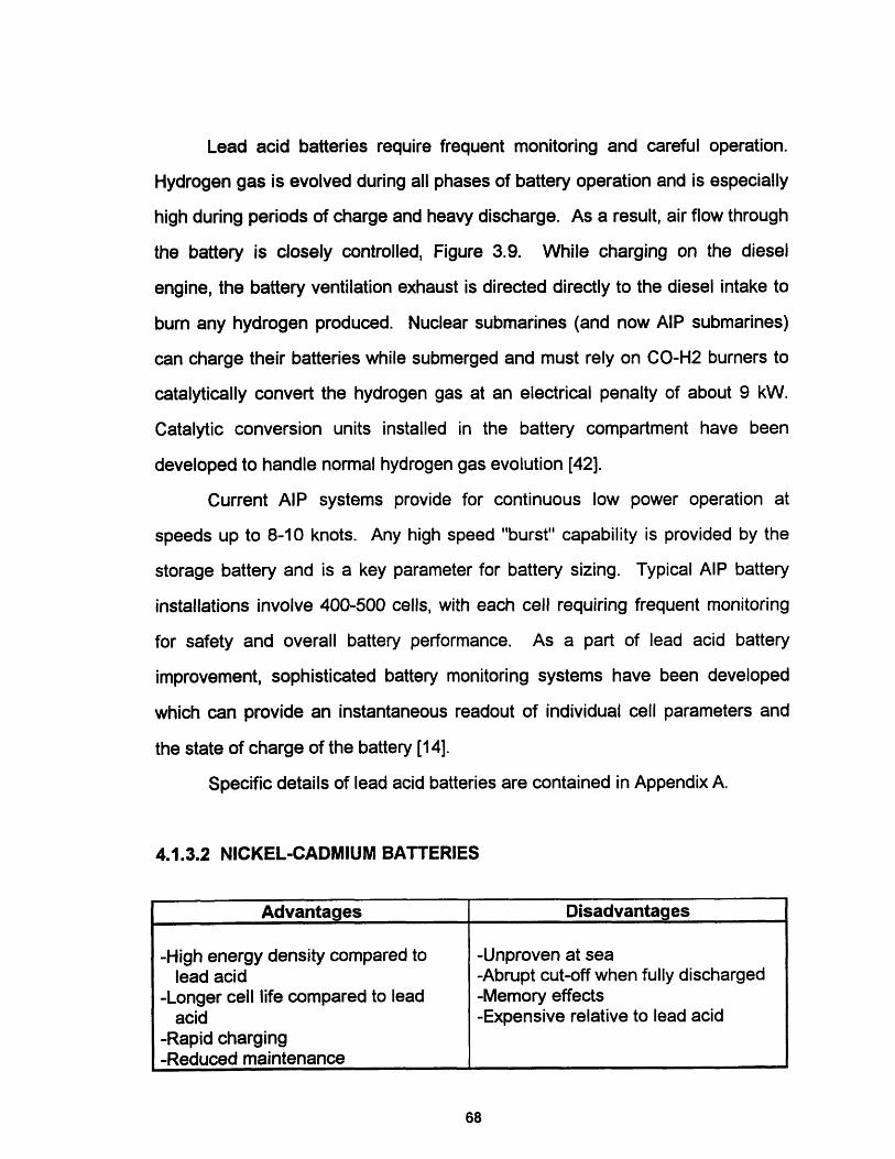
4.1.3.2 NICKEL-CADMIUM BATTERIES
68
Advantages Disadvantages
-High energy density compared to -Unproven at sealead acid -Abrupt cut-off when fully discharged
-Longer cell life compared to lead -Memory effectsacid -Expensive relative to lead acid
-Rapid charging-Reduced maintenance
Nickel-Cadmium (Ni/Cd) battery technology is well established for
commercial use, but in sizes much smaller than that required for submarine
applications. Virtually any portable rechargeable electric tool or appliance is
powered by Ni/Cd batteries. No Ni/Cd battery systems have been installed in a
full sized submarine.
The Ni/Cd battery is schematically similar to the lead acid battery in
Figure 4.7, with positive nickel hydroxide plates and negative cadmium plates in
a potassium hydroxide electrolyte, transferring energy according to the following
equation:
Discharge
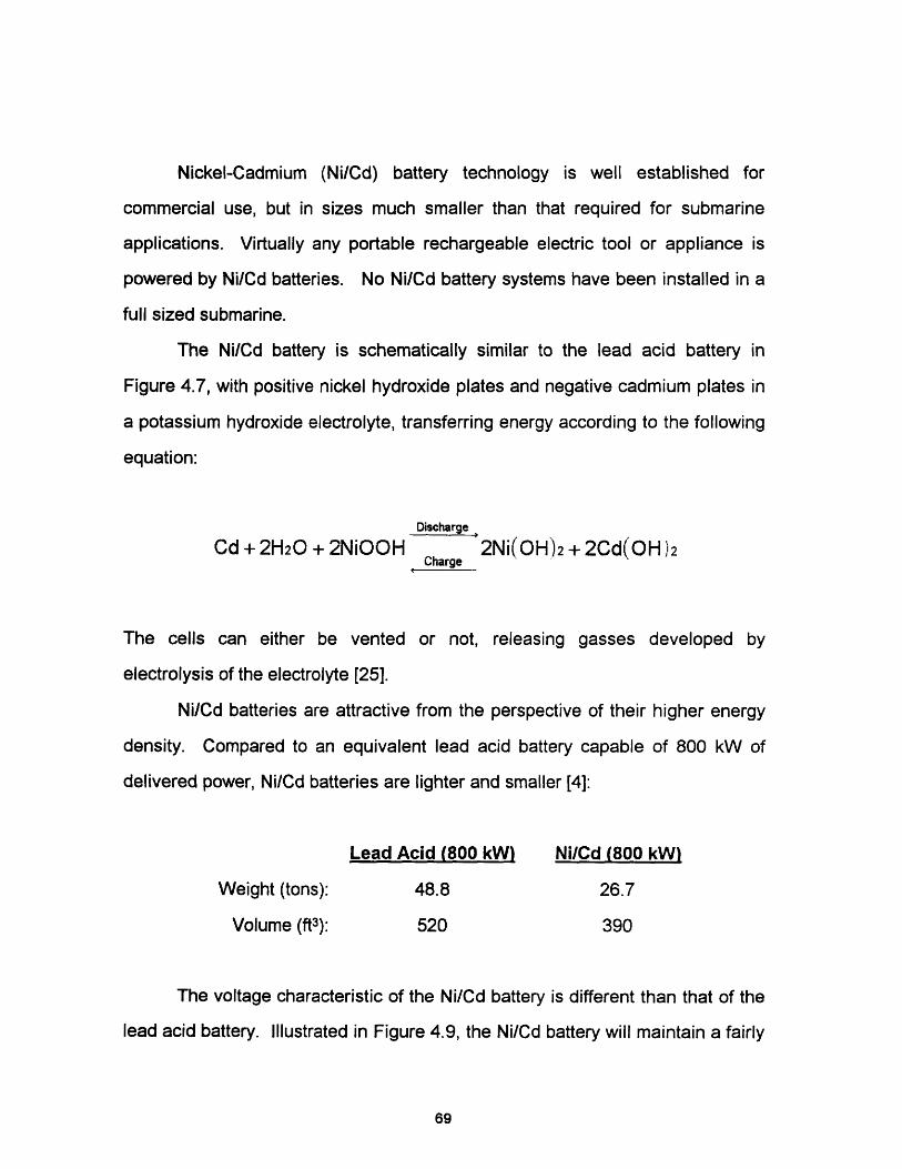
Cd + 2H20 + 2NiOOH 2Ni(OH)2 + 2Cd( OH 2Charge
The cells can either be vented or not, releasing gasses developed by
electrolysis of the electrolyte [25].
Ni/Cd batteries are attractive from the perspective of their higher energy
density. Compared to an equivalent lead acid battery capable of 800 kW of
delivered power, Ni/Cd batteries are lighter and smaller [4]:
Lead Acid (800 kW) Ni/Cd (800 kW)
Weight (tons): 48.8 26.7
Volume (ft3): 520 390
The voltage characteristic of the Ni/Cd battery is different than that of the
lead acid battery. Illustrated in Figure 4.9, the Ni/Cd battery will maintain a fairly
69
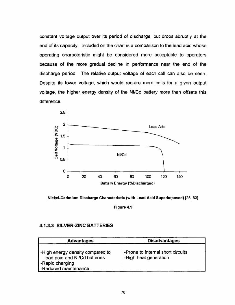
constant voltage output over its period of discharge, but drops abruptly at the
end of its capacity. Included on the chart is a comparison to the lead acid whose
operating characteristic might be considered more acceptable to operators
because of the more gradual decline in performance near the end of the
discharge period. The relative output voltage of each cell can also be seen.
Despite its lower voltage, which would require more cells for a given output
voltage, the higher energy density of the Ni/Cd battery more than offsets this
difference.
'31;
2
01.5
W
Lead Acid
Ni/Cd
I , I , , I
0 20 40 60 80 100 120 140
Battery Energy (%Discharged)
Nickel-Cadmium Discharge Characteristic (with Lead Acid Superimposed) [25, 63]
Figure 4.9
4.1.3.3 SILVER-ZINC BATTERIES
70
Advantages Disadvantages
-High energy density compared to -Prone to internal short circuitslead acid and Ni/Cd batteries -High heat generation
-Rapid charging-Reduced maintenance
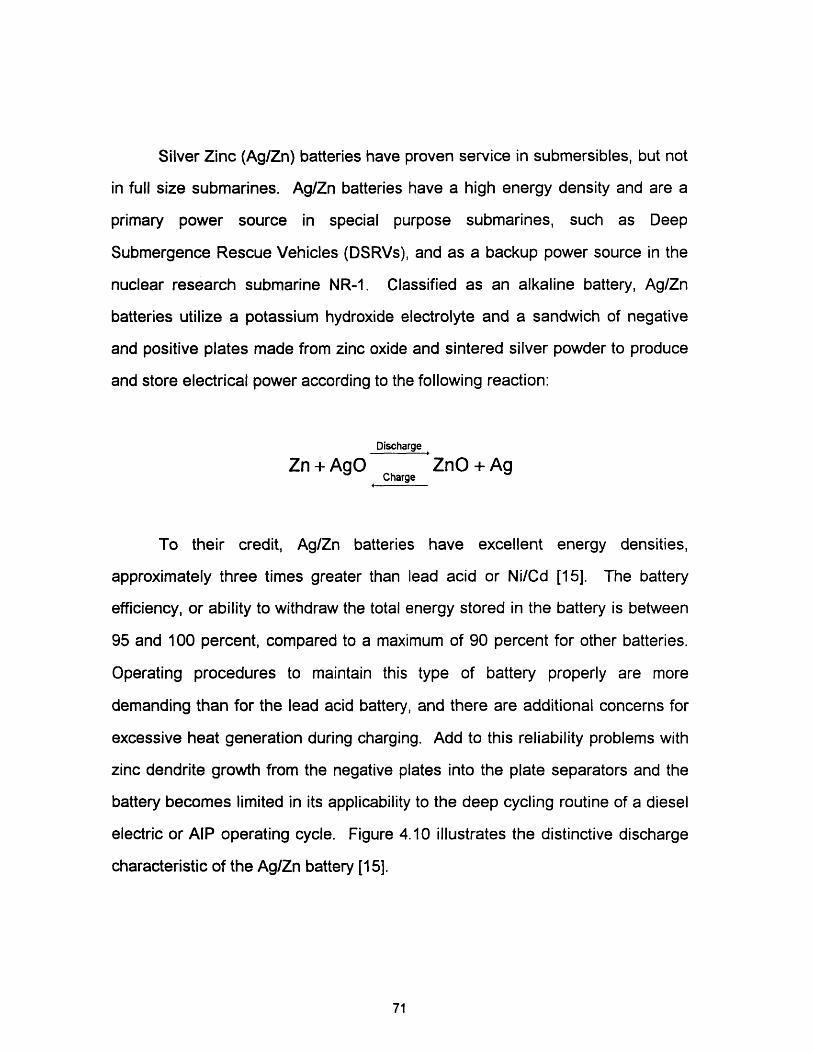
Silver Zinc (Ag/Zn) batteries have proven service in submersibles, but not
in full size submarines. Ag/Zn batteries have a high energy density and are a
primary power source in special purpose submarines, such as Deep
Submergence Rescue Vehicles (DSRVs), and as a backup power source in the
nuclear research submarine NR-1. Classified as an alkaline battery, Ag/Zn
batteries utilize a potassium hydroxide electrolyte and a sandwich of negative
and positive plates made from zinc oxide and sintered silver powder to produce
and store electrical power according to the following reaction:
Discharge
Zn + AgO ZnO + AgCharge
To their credit, Ag/Zn batteries have excellent energy densities,
approximately three times greater than lead acid or Ni/Cd [15]. The battery
efficiency, or ability to withdraw the total energy stored in the battery is between
95 and 100 percent, compared to a maximum of 90 percent for other batteries.
Operating procedures to maintain this type of battery properly are more
demanding than for the lead acid battery, and there are additional concerns for
excessive heat generation during charging. Add to this reliability problems with
zinc dendrite growth from the negative plates into the plate separators and the
battery becomes limited in its applicability to the deep cycling routine of a diesel
electric or AIP operating cycle. Figure 4.10 illustrates the distinctive discharge
characteristic of the Ag/Zn battery [15].
71
2
o
ao
1
o0 20 40 80 100 120
Battery Energy (% Discharged)
Silver Zinc Discharge Characteristics
Figure 4.10
4.1.3.4 LITHIUM-ALUMINUM / IRON SULFIDE
The Lithium-Aluminum / Iron Sulfide (LAIS) battery is the most promising
of several high temperature storage batteries currently under development. The
United Kingdom has a strong research program underway to develop a reliable
replacement system for the standard lead acid batteries in their diesel electric
72
Advantages Disadvantages
-High energy density compared to -Not mature technologylead acid and Ni/Cd batteries -High operating temperatures
-Rapid charging -Battery must be heated before-Reduced maintenance operating-High energy efficiency
I~~~~~~~~~~~~~ ~ ~ ~~~~~~~~~~~~~~~~~~~~~~~~~~~~~~~~~~~~~~~~~~~~~~~~~~~~~~~~~~~~~~~~~~~~~~~~~~~~~~~~~~~~~~~~~~~~~~~~
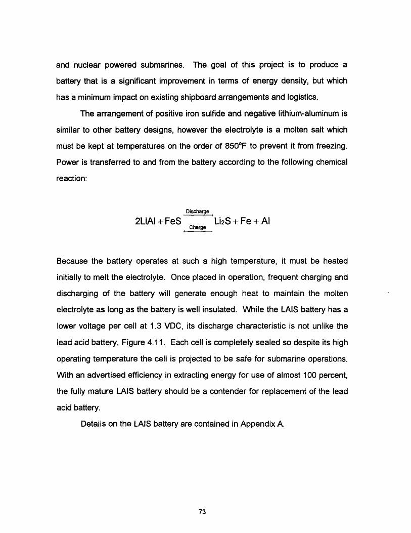
and nuclear powered submarines. The goal of this project is to produce a
battery that is a significant improvement in terms of energy density, but which
has a minimum impact on existing shipboard arrangements and logistics.
The arrangement of positive iron sulfide and negative lithium-aluminum is
similar to other battery designs, however the electrolyte is a molten salt which
must be kept at temperatures on the order of 8500 F to prevent it from freezing.
Power is transferred to and from the battery according to the following chemical
reaction:
Discharge
2LiAI + FeS Li2S + Fe + AlCharge
Because the battery operates at such a high temperature, it must be heated
initially to melt the electrolyte. Once placed in operation, frequent charging and
discharging of the battery will generate enough heat to maintain the molten
electrolyte as long as the battery is well insulated. While the LAIS battery has a
lower voltage per cell at 1.3 VDC, its discharge characteristic is not unlike the
lead acid battery, Figure 4.11. Each cell is completely sealed so despite its high
operating temperature the cell is projected to be safe for submarine operations.
With an advertised efficiency in extracting energy for use of almost 100 percent,
the fully mature LAIS battery should be a contender for replacement of the lead
acid battery.
Details on the LAIS battery are contained in Appendix A.
73
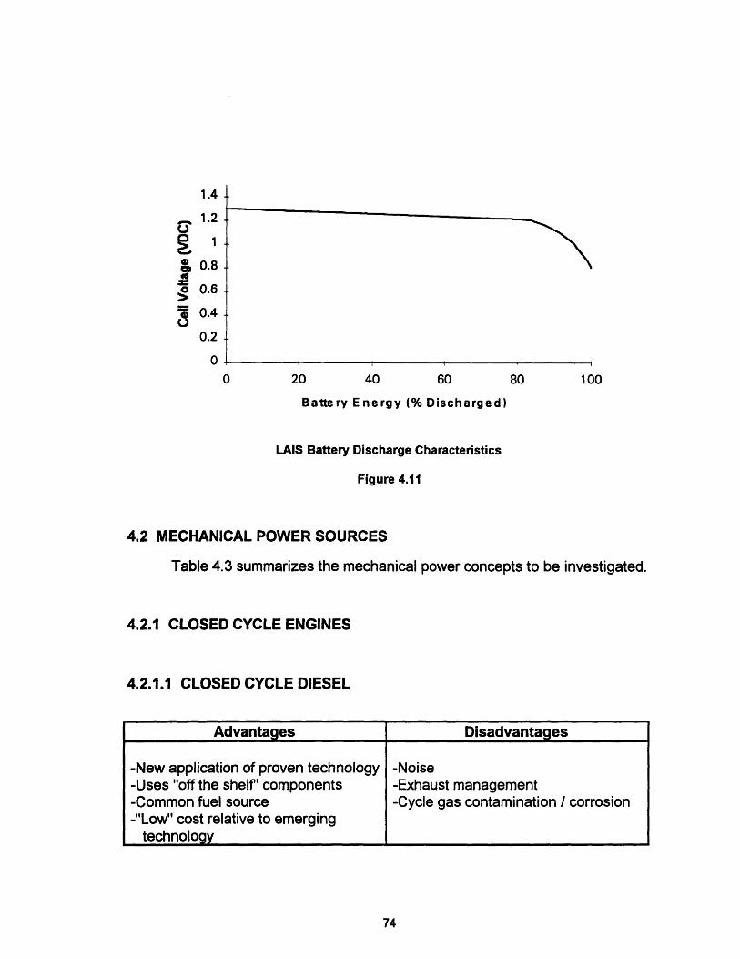
I01>0
8
1.4 .
1.2 .
1-
0.8 .
0.6
0.4 -
0.2
n
0 20 40 60 80 100
Battery Energy (% Discharged)
LAIS Battery Discharge Characteristics
Figure 4.11
4.2 MECHANICAL POWER SOURCES
Table 4.3 summarizes the mechanical power concepts to be investigated.
4.2.1 CLOSED CYCLE ENGINES
4.2.1.1 CLOSED CYCLE DIESEL
74
Advantages Disadvantages
-New application of proven technology -Noise-Uses "off the shelf' components -Exhaust management-Common fuel source -Cycle gas contamination / corrosion-"Low" cost relative to emerging
technology
v-

Table 4.3
Mechanical AIP Concepts
By far the most popular mechanical source among nations investigating
AIP is the closed cycle diesel (CCD) engine. Investigated as a possible method
to improve underwater endurance as early as 1901, this technology is based on
the adaptation of proven diesel engines to the underwater operating
environment, and is currently being pursued either singly or in partnerships by
Italy, the United Kingdom, Germany, the Netherlands and others [52]. The
former Soviet Union is believed to have the most experience with a combatant
CCD submarine, the BELUGA, although few details are known [65]. To date,
most systems demonstrated at sea are for commercial or research purposes at
up to 600 kW. The CCD system can operate either closed or open cycle with air
from the atmosphere since it is based on standard diesel engine. Figure 4.12
illustrates the CCD concept. Focusing on the air intake and exhaust system in
the closed cycle mode, engine exhaust gasses are cooled and passed though
an absorber unit where they are sprayed with low pressure seawater to absorb
the CO2 in the mixture. The resultant mixture is then replenished with oxygen
75
Power Sources (Mechanical) Remarks
Closed Cycle Diesel Mature, lowest cost system
Stirling Engines Mature, low power only
Closed Brayton Cycles Excellent potential for development
Rankine Cycles Proven technology
Small Nuclear Power Under development
Walter Cycles Safety of H909

COSWORTH SYSTEM
I =e'-~-~~~ , Closed Cycle Operation MANAGEMENTSYSTEM Overboard
*._ Open Cycle Operation
Closed Cycle Diesel with Exhaust Management System [54]
Figure 4.12
and an inert gas such as argon and returned to the engine intake to repeat the
cycle. The Cosworth exhaust management system (developed by Cosworth
Engineering, UK) consists of a high and low pressure seawater loop and is
discussed further in Section 5.3. At sea test results by a German CCD
consortium headed by Thyssen Nordseewere showed that the CCD suffers a 5
percent increase in fuel consumption and a 15 percent loss in brake power to
overcome the effects of discharging CO2 at pressures other than atmospheric
[8].
76

The introduction of makeup gasses such as oxygen and argon are
important for several reasons. Oxygen is obvious, for without it the engine could
not sustain combustion. As for argon or other inert gas, this makeup volume is
important to replace the CO2, water and other gases stripped in the absorber
unit. CO2 is a triatomic gas with a low ratio of specific heats (). Studies have
shown that by leaving CO2 alone as the makeup gas, Y for the engine
atmosphere would be too low, reducing the pressure rise during compression
needed to sustain combustion, forcing physical changes in the engine increasing
the compression ratio beyond acceptable limits [50]. The long term effects of
sulfuric acid and other contaminants in the atmosphere are also of significant
concern. Studies to determine the appropriate synthetic atmosphere
composition continue.
Details of a typical CCD system are contained in Appendix A.
4.2.1.2 CLOSED BRAYTON CYCLE
The Closed Brayton Cycle (CBC) is an AIP application of the basic gas
turbine engine. While the concept is plausible and interest has been expressed
in developing such a system by several countries, including the United States as
a possible replacement for emergency diesel engines on nuclear submarines,
77
Advantages Disadvantages
-Strong technical base -Immature as a closed cycle-Quiet signature (high frequency) -Combustion product management-Low power compact engine -High temperature corrosion problems
demonstrated in direct combustion applications-High power density-Variety of fuel sources

other, more mature technologies such as the closed cycle diesel and Stirling
engines have so far limited development of the CBC engine [65].
Several papers have been presented on the specifics of the CBC, scaling
parameters from proven low power designs from other applications. One
compact concept designed for UUV and submarine applications is shown in
Figure 4.13, with the gas cycle in Figure 4.14. The system, classified as indirect
combustion, consists of two cycles, a working gas cycle at high pressure with a
monatomic gas (Helium, Xenon, etc.) operating between a turbine and
compressor through a recuperator, and a combustion cycle transferring the heat
of combustion through a heat exchanger to the working fluid cycle. Cycle
efficiency for this system is claimed to potentially exceed 50 percent [26].
Another possible design could be a direct combustion cycle utilizing a
synthetic atmosphere similar to that described for the CCD, however such a
system would bring with it high temperature corrosion problems [58].
Additional details on CBC are contained in Appendix A.
Closed Brayton Cycle Combustion Power System [58]
Figure 4.13
78

RECUPERATOR
Closed Brayton Cycle Schematic Flow Diagram [58]
Figure 4.14
4.2.2 STIRLING ENGINE
The Stirling engine is an established heat engine concept that has
recently and successfully been applied to service in submarines. The Swedish
government has operated a 150 kW Stirling AIP power system at sea in
79
Advantages Disadvantages
-Proven by Sweden at sea -Noise-Common fuel source -Exhaust management-Adaptable as a bottoming cycle -High temperature corrosion-Low vibration compared to CCD -Complicated-Reliable operating profile -Presently limited in size-High Efficiency
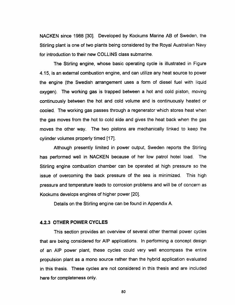
NACKEN since 1988 [30]. Developed by Kockums Marine AB of Sweden, the
Stirling plant is one of two plants being considered by the Royal Australian Navy
for introduction to their new COLLINS class submarine.
The Stirling engine, whose basic operating cycle is illustrated in Figure
4.15, is an external combustion engine, and can utilize any heat source to power
the engine (the Swedish arrangement uses a form of diesel fuel with liquid
oxygen). The working gas is trapped between a hot and cold piston, moving
continuously between the hot and cold volume and is continuously heated or
cooled. The working gas passes through a regenerator which stores heat when
the gas moves from the hot to cold side and gives the heat back when the gas
moves the other way. The two pistons are mechanically linked to keep the
cylinder volumes properly timed [17].
Although presently limited in power output, Sweden reports the Stirling
has performed well in NACKEN because of her low patrol hotel load. The
Stirling engine combustion chamber can be operated at high pressure so the
issue of overcoming the back pressure of the sea is minimized. This high
pressure and temperature leads to corrosion problems and will be of concern as
Kockums develops engines of higher power [20].
Details on the Stirling engine can be found in Appendix A.
4.2.3 OTHER POWER CYCLES
This section provides an overview of several other thermal power cycles
that are being considered for AIP applications. In performing a concept design
of an AIP power plant, these cycles could very well encompass the entire
propulsion plant as a mono source rather than the hybrid application evaluated
in this thesis. These cycles are not considered in this thesis and are included
here for completeness only.
80
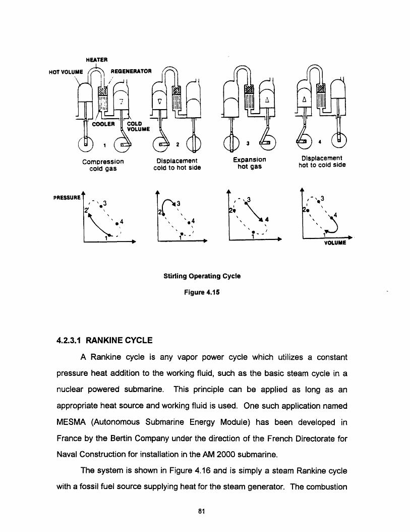
HEATER
HOT VOLU
Compression Displacement Expansioncold gas cold to hot side hot gas
,- 3
' 4
'3
\4'.4
Displacementhot to cold side
, "2®
4'lq~ ---
VOLUME
Stirling Operating Cycle
Figure 4.15
4.2.3.1 RANKINE CYCLE
A Rankine cycle is any vapor power cycle which utilizes a constant
pressure heat addition to the working fluid, such as the basic steam cycle in a
nuclear powered submarine. This principle can be applied as long as an
appropriate heat source and working fluid is used. One such application named
MESMA (Autonomous Submarine Energy Module) has been developed in
France by the Bertin Company under the direction of the French Directorate for
Naval Construction for installation in the AM 2000 submarine.
The system is shown in Figure 4.16 and is simply a steam Rankine cycle
with a fossil fuel source supplying heat for the steam generator. The combustion
81
v .
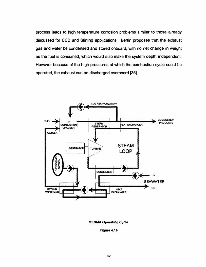
process leads to high temperature corrosion problems similar to those already
discussed for CCD and Stirling applications. Bertin proposes that the exhaust
gas and water be condensed and stored onboard, with no net change in weight
as the fuel is consumed, which would also make the system depth independent.
However because of the high pressures at which the combustion cycle could be
operated, the exhaust can be discharged overboard [35].
COMBUSTIONPRODUCTS
JTER
MESMA Operating Cycle
Figure 4.16
82

4.2.3.2 SMALL NUCLEAR POWER
This AIP option is not simply a scaled down version of a larger nuclear
propulsion plant, but rather a low power cycle designed to meet hotel load
requirements and recharge batteries while submerged. This system is being
developed in Canada by Energy Conversion Systems under the title
Autonomous Marine Power Source (AMPS). The obvious contribution of AMPS
is that it can provide a conventional submarine with seemingly infinite
endurance, but not high sustained speed, at what is hoped to be reduced cost.
As with a full sized nuclear power option, the political climate and infrastructure
development associated with a nuclear propulsion program may be too great for
many countries [29]. Illustrated in Figure 4.17, the AMPS concept features a low
power, low temperature pressurized water nuclear power source which is
perceived as being safer than a high temperature concept. Heat is transferred
to a secondary Rankine cycle where electrical power is produced. Current plans
call for a 100 kW plant which could be scaled to 400 kW [23].
4.2.3.3 WALTER CYCLE
The Walter Cycle is a power cycle based on hydrogen peroxide as an
oxidizer and is included for a historical perspective since no countries presently
show interest in such a power source for submarines, although Sweden employs
hydrogen peroxide and diesel fuel for torpedo propulsion [20]. Developed in
Germany during World War II, Walter cycle power plants were installed in
several experimental submarines, proving their high power density, limited only
in their ability to carry reactants. The Germans expected speeds of 24 knots in
their Type XXVI submarines while the United Kingdom achieved 26 knot
performance for periods of up to three hours in EXPLORER during the 1950's
83

WATER
AMPS Power Cycle
Figure 4.17
[43]. The United Kingdom abandoned Walter cycle development with the advent
of nuclear propulsion.
Shown in Figure 4.18, the Walter cycle combines diesel fuel and high test
(80 percent) peroxide (HTP) to produce a high pressure and temperature mixture
of carbon dioxide and steam. HTP is first passed into a catalyst where it
decomposes in an exothermic reaction, producing oxygen and water (steam).
The oxygen is then passed to a combustion chamber where it is combined with
diesel fuel and ignited. Water is also admitted to the combustion chamber to
limit the temperature rise and form additional steam. The resultant steam and
exhaust product mixture is then directed to a turbine for propulsion power.
84
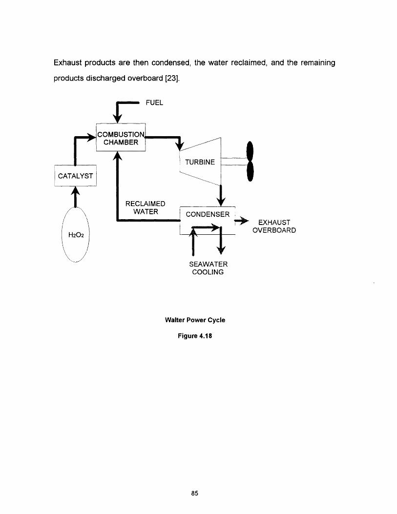
Exhaust products are then condensed, the water reclaimed, and the remaining
products discharged overboard [23].
EXHAUSTOVERBOARD
S AWA IRCOOLING
Walter Power Cycle
Figure 4.18
85

(Blank Reverse)
86
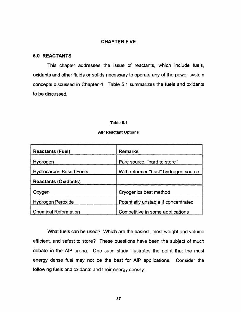
CHAPTER FIVE
5.0 REACTANTS
This chapter addresses the issue of reactants, which include fuels,
oxidants and other fluids or solids necessary to operate any of the power system
concepts discussed in Chapter 4. Table 5.1 summarizes the fuels and oxidants
to be discussed.
Table 5.1
AlP Reactant Options
What fuels can be used? Which are the easiest, most weight and volume
efficient, and safest to store? These questions have been the subject of much
debate in the AIP arena. One such study illustrates the point that the most
energy dense fuel may not be the best for AIP applications. Consider the
following fuels and oxidants and their energy density:
87
Reactants (Fuel) Remarks
Hydrogen Pure source, "hard to store"
Hydrocarbon Based Fuels With reformer-"best" hydrogen source
Reactants (Oxidants)
Oxygen Cryogenics best method
Hydrogen Peroxide Potentially unstable if concentrated
Chemical Reformation Competitive in some applications
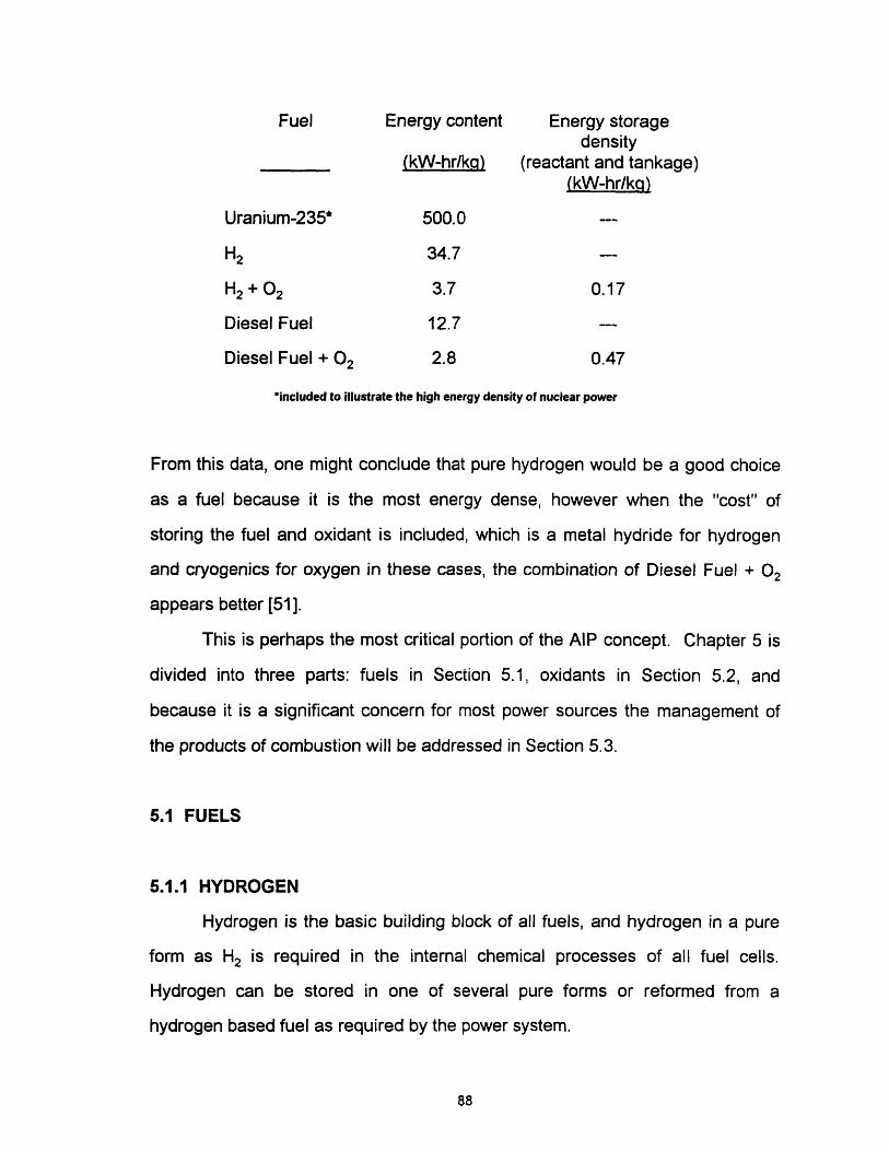
Fuel Energy content Energy storagedensity
(kW-hr/kq) (reactant and tankage)(kW-hr/kq)
Uranium-235* 500.0
H2 34.7
H2 + 02 3.7 0.17
Diesel Fuel 12.7
Diesel Fuel + 02 2.8 0.47
'included to illustrate the high energy density of nuclear power
From this data, one might conclude that pure hydrogen would be a good choice
as a fuel because it is the most energy dense, however when the "cost" of
storing the fuel and oxidant is included, which is a metal hydride for hydrogen
and cryogenics for oxygen in these cases, the combination of Diesel Fuel + 02
appears better [51].
This is perhaps the most critical portion of the AIP concept. Chapter 5 is
divided into three parts: fuels in Section 5.1, oxidants in Section 5.2, and
because it is a significant concern for most power sources the management of
the products of combustion will be addressed in Section 5.3.
5.1 FUELS
5.1.1 HYDROGEN
Hydrogen is the basic building block of all fuels, and hydrogen in a pure
form as H2 is required in the internal chemical processes of all fuel cells.
Hydrogen can be stored in one of several pure forms or reformed from a
hydrogen based fuel as required by the power system.
88

5.1.1.1 HYDROGEN - GASEOUS STORAGE
Although the storage density for this form is very poor, gaseous storage is
used extensively in industry where transportation of small volumes of gas are
required. Increasing the gas pressure will allow more H2 to be stored but will
also increase the size and weight of the storage cylinder. A standard high
pressure cylinder, 42.5 liters at 6000 psi, would contain only 1.23 kg of H2 while
the cylinder plus H2 weighs 138.8 kg for a H2 weight percentage of 0.87 percent.
At this high pressure, the energy contained in the compressed gas represents a
significant hazard should the tank rupture, thus strong consideration would be
given to placing the tank outsides the pressure hull. Precautions must also be
taken to prevent hydrogen embrittlement of the cylinders though the use of
special materials and to ensure the cylinders meet established shock
performance standards [57].
5.1.1.2 HYDROGEN - CRYOGENIC STORAGE
Cryogenic storage of any gas as a liquid is more beneficial from the
perspective that more of the gas can be carried for a given available volume.
But as with gaseous storage, the penalty of this form of storage lies in the
extraordinary measures which must be taken to maintain the cryogenic
conditions.
Storage of cryogenic liquids has been investigated extensively with super
insulated dewars being the accepted form of cryogenic storage. In this scenario,
liquid hydrogen (LH) would be loaded at the beginning of a mission, and some
boil off accepted due to inevitable heat conduction into the tank. This
phenomena is especially critical for LH whose boiling point is 200K. Accounting
for this boil off means that additional hydrogen beyond that for mission
requirements must be loaded, plus some method devised to deal with the
89
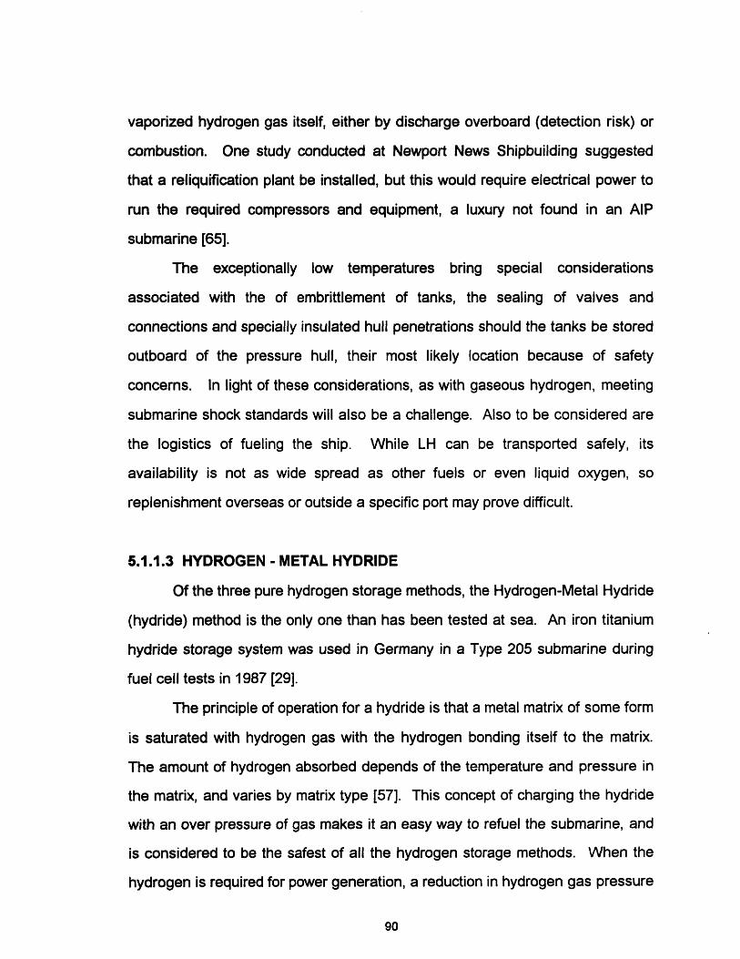
vaporized hydrogen gas itself, either by discharge overboard (detection risk) or
combustion. One study conducted at Newport News Shipbuilding suggested
that a reliquification plant be installed, but this would require electrical power to
run the required compressors and equipment, a luxury not found in an AIP
submarine [65].
The exceptionally low temperatures bring special considerations
associated with the of embrittlement of tanks, the sealing of valves and
connections and specially insulated hull penetrations should the tanks be stored
outboard of the pressure hull, their most likely location because of safety
concerns. In light of these considerations, as with gaseous hydrogen, meeting
submarine shock standards will also be a challenge. Also to be considered are
the logistics of fueling the ship. While LH can be transported safely, its
availability is not as wide spread as other fuels or even liquid oxygen, so
replenishment overseas or outside a specific port may prove difficult.
5.1.1.3 HYDROGEN - METAL HYDRIDE
Of the three pure hydrogen storage methods, the Hydrogen-Metal Hydride
(hydride) method is the only one than has been tested at sea. An iron titanium
hydride storage system was used in Germany in a Type 205 submarine during
fuel cell tests in 1987 [29].
The principle of operation for a hydride is that a metal matrix of some form
is saturated with hydrogen gas with the hydrogen bonding itself to the matrix.
The amount of hydrogen absorbed depends of the temperature and pressure in
the matrix, and varies by matrix type [57]. This concept of charging the hydride
with an over pressure of gas makes it an easy way to refuel the submarine, and
is considered to be the safest of all the hydrogen storage methods. When the
hydrogen is required for power generation, a reduction in hydrogen gas pressure
90
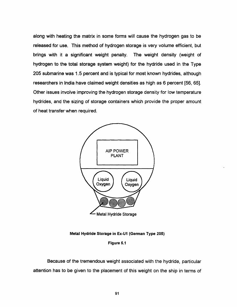
along with heating the matrix in some forms will cause the hydrogen gas to be
released for use. This method of hydrogen storage is very volume efficient, but
brings with it a significant weight penalty. The weight density (weight of
hydrogen to the total storage system weight) for the hydride used in the Type
205 submarine was 1.5 percent and is typical for most known hydrides, although
researchers in India have claimed weight densities as high as 6 percent [56, 65].
Other issues involve improving the hydrogen storage density for low temperature
hydrides, and the sizing of storage containers which provide the proper amount
of heat transfer when required.
IvlcLll nyul luG LVl cly
Metal Hydride Storage in Ex-U1 (German Type 205)
Figure 5.1
Because of the tremendous weight associated with the hydride, particular
attention has to be given to the placement of this weight on the ship in terms of
91
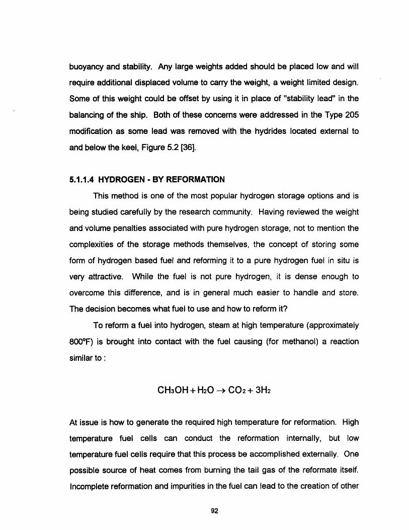
buoyancy and stability. Any large weights added should be placed low and will
require additional displaced volume to carry the weight, a weight limited design.
Some of this weight could be offset by using it in place of "stability lead" in the
balancing of the ship. Both of these concerns were addressed in the Type 205
modification as some lead was removed with the hydrides located external to
and below the keel, Figure 5.2 [36].
5.1.1.4 HYDROGEN - BY REFORMATION
This method is one of the most popular hydrogen storage options and is
being studied carefully by the research community. Having reviewed the weight
and volume penalties associated with pure hydrogen storage, not to mention the
complexities of the storage methods themselves, the concept of storing some
form of hydrogen based fuel and reforming it to a pure hydrogen fuel in situ is
very attractive. While the fuel is not pure hydrogen, it is dense enough to
overcome this difference, and is in general much easier to handle and store.
The decision becomes what fuel to use and how to reform it?
To reform a fuel into hydrogen, steam at high temperature (approximately
8000F) is brought into contact with the fuel causing (for methanol) a reaction
similar to:
CH30H + H20 - C02 + 3H2
At issue is how to generate the required high temperature for reformation. High
temperature fuel cells can conduct the reformation internally, but low
temperature fuel cells require that this process be accomplished externally. One
possible source of heat comes from burning the tail gas of the reformate itself.
Incomplete reformation and impurities in the fuel can lead to the creation of other
92

gasses, such as carbon monoxide, nitrogen and methane. Of these gasses,
carbon monoxide will poison the PEM cell, severely decreasing its power output.
The elimination of carbon monoxide is a developmental issue for reformers [3].
Typical candidate fuels for reformation include diesel fuel, methanol and
ethanol. Diesel fuel is easy to handle, fully compatible with submarine
operations and available world-wide. Reformation methods for diesel fuel have
been developed, but extra processes to ensure the elimination of carbon
monoxide make this process more cumbersome. Methanol and ethanol can be
reformed while minimizing the production of carbon monoxide, with methanol
producing more hydrogen gas per mole of fuel [3]. The ethanol reformation
process also requires more water, and produces more carbon dioxide which
must be disposed of [13]. Methanol is a synthetic fuel that is in ample supply
because of its interest as a replacement fuel for automobiles. Methanol however
is immiscible in water, requiring it to be stored in its own tank, or in seawater
compensated tanks with bladders separating the fuel and water.
One other reformation process has been suggested for AIP applications,
and involves the transformation of a hydrocarbon fuel form one form to another,
releasing hydrogen gas in the process. A proven technology in the chemical
industry, one example fuel to be reformed is cyclohexane,
C6H12 , C6H6 + 3H2Reformer
producing 56 grams of hydrogen per 780 grams of cyclohexane (>7% H2 by
weight) [26].
93
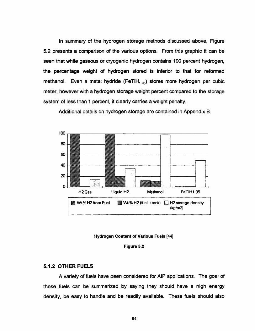
In summary of the hydrogen storage methods discussed above, Figure
5.2 presents a comparison of the various options. From this graphic it can be
seen that while gaseous or cryogenic hydrogen contains 100 percent hydrogen,
the percentage weight of hydrogen stored is inferior to that for reformed
methanol. Even a metal hydride (FeTiH1.5) stores more hydrogen per cubic
meter, however with a hydrogen storage weight percent compared to the storage
system of less than 1 percent, it clearly carries a weight penalty.
Additional details on hydrogen storage are contained in Appendix B.
,I f%Iw
80
60
40
20
0 IJ Z-.,H2 Gas Uquid H2 Meihanol FeTiH 1.95
U Wt% H2 from Fuel L Wt% H2 (fuel +tank) El H2 storage density(kg/m3)
Hydrogen Content of Various Fuels [44]
Figure 5.2
5.1.2 OTHER FUELS
A variety of fuels have been considered for AIP applications. The goal of
these fuels can be summarized by saying they should have a high energy
density, be easy to handle and be readily available. These fuels should also
94
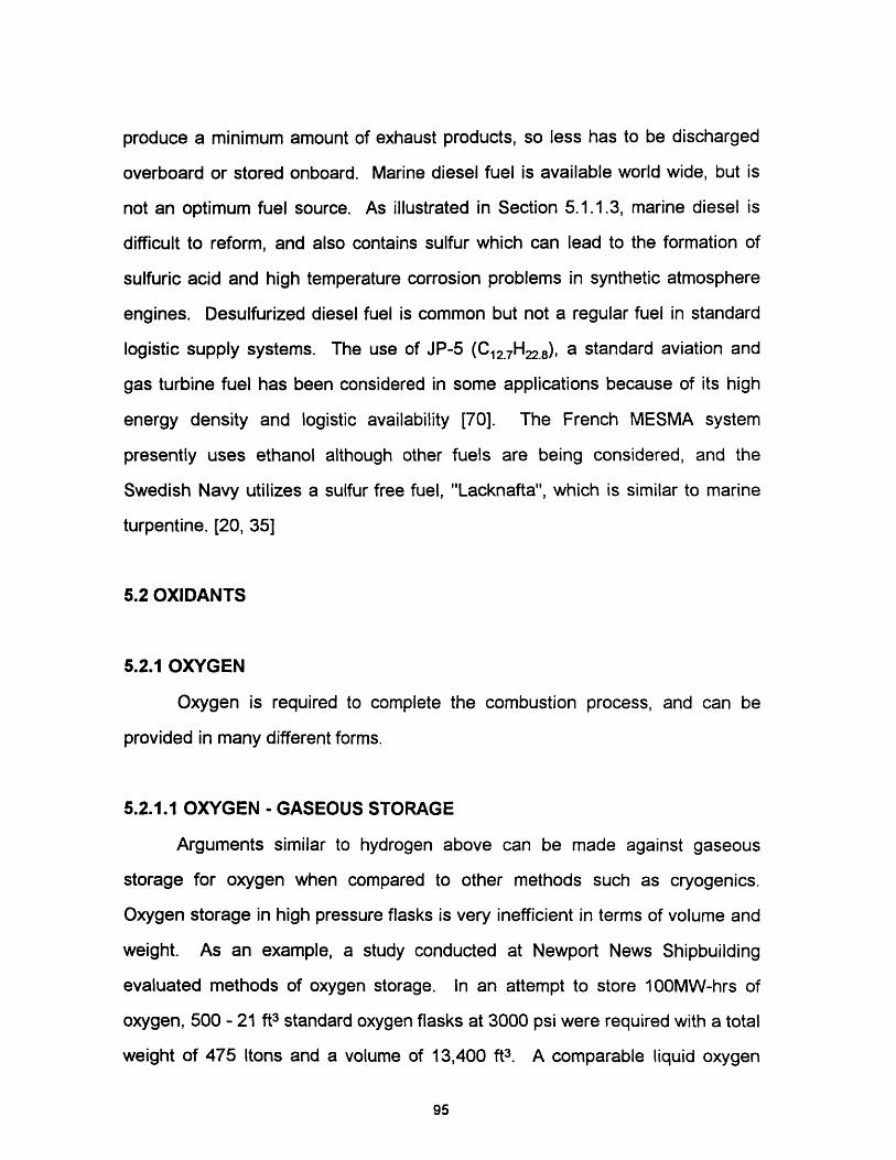
produce a minimum amount of exhaust products, so less has to be discharged
overboard or stored onboard. Marine diesel fuel is available world wide, but is
not an optimum fuel source. As illustrated in Section 5.1.1.3, marine diesel is
difficult to reform, and also contains sulfur which can lead to the formation of
sulfuric acid and high temperature corrosion problems in synthetic atmosphere
engines. Desulfurized diesel fuel is common but not a regular fuel in standard
logistic supply systems. The use of JP-5 (C12 7H22.8), a standard aviation and
gas turbine fuel has been considered in some applications because of its high
energy density and logistic availability [70]. The French MESMA system
presently uses ethanol although other fuels are being considered, and the
Swedish Navy utilizes a sulfur free fuel, "Lacknafta", which is similar to marine
turpentine. [20, 35]
5.2 OXIDANTS
5.2.1 OXYGEN
Oxygen is required to complete the combustion process, and can be
provided in many different forms.
5.2.1.1 OXYGEN - GASEOUS STORAGE
Arguments similar to hydrogen above can be made against gaseous
storage for oxygen when compared to other methods such as cryogenics.
Oxygen storage in high pressure flasks is very inefficient in terms of volume and
weight. As an example, a study conducted at Newport News Shipbuilding
evaluated methods of oxygen storage. In an attempt to store 100MW-hrs of
oxygen, 500 - 21 ft3 standard oxygen flasks at 3000 psi were required with a total
weight of 475 Itons and a volume of 13,400 ft3. A comparable liquid oxygen
95

system would weigh 109 Itons and displace 3348 ft3 illustrating the efficiency of
liquid oxygen storage [65].
One novel method of gaseous oxygen storage has been proposed by an
Italian company, Fincantieri, employing torroidal gas cylinders which are welded
together to form a pressure hull. This method helps to alleviate the weight and
volume penalties of gaseous oxygen storage by replacing ship structure with
oxygen cylinders. The cylinders are designed to store the oxygen at 4000 psi
and also store exhaust products from a CCD engine [66]. This principle is
illustrated in Figure 5.3. One obvious concern with this design is that while the
individual torroids are no doubt sturdy, can the process of joining these torroids
together form a pressure hull that is strong enough to withstand shock and can
be adequately inspected for cracks and corrosion.
Pressure Hull r H Torroidal Cylinders )
Torroidal Gaseous Oxygen Storage Concept
Figure 5.3
5.2.1.2 OXYGEN - CRYOGENIC STORAGE
This method is considered to be the best option for storage onboard an
AIP vessel. More volume efficient than gaseous storage, an extensive
96

experience base exists for the handling of liquid oxygen (LOX). Storage tanks
would be comprised of super insulated dewars, with a typical storage
temperature of 900K (-1830C). Based on typical tank arrangements, the boil off
would be approximately one percent of the volume per day [7]. Unlike hydrogen
above, this boil off is beneficial with the vaporized oxygen used as breathing
oxygen for the crew.
In an effort to reduce the heat absorption of the LOX, large tanks are
more efficient, but become more difficult to place on the submarine. There are
many safety concerns associated with LOX storage inside the pressure hull to
include:
-Failure of tank, flooding the ship with oxygen (oxygen poisoning)
-Increased fire potential
-Cryogenic contact with sensitive materials (such as HY steel hull)
[31].
Sweden has adopted LOX storage for use in NAECKEN and has reported no
operational problems to date. Their concept is similar to that pictured in Figure
5.1, with two double insulated LOX tanks contained in an isolated LOX
compartment equipped with monitoring equipment and an overboard venting
system for emergencies. In this arrangement, all the LOX piping is completely
shielded from the crew, much the same as a reactor compartment onboard a
nuclear submarine [20]. A study conducted by Johns Hopkins University Applied
Physics Laboratory in the 1980's investigated the replacement of oxygen
generators with cryogenic oxygen tanks, envisioning a storage system with tanks
located in the ballast tanks external to the pressure hull. In this study,
placement of the tanks in the corrosive environment of the sea was judged to be
97
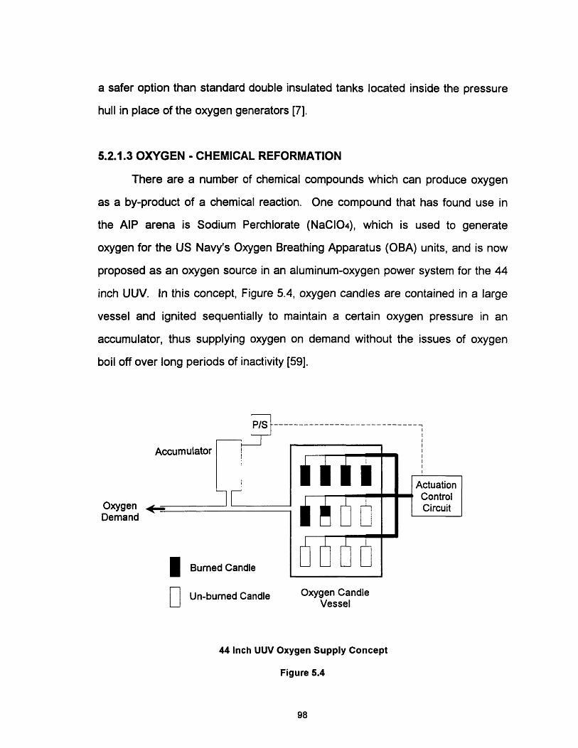
a safer option than standard double insulated tanks located inside the pressure
hull in place of the oxygen generators [7].
5.2.1.3 OXYGEN - CHEMICAL REFORMATION
There are a number of chemical compounds which can produce oxygen
as a by-product of a chemical reaction. One compound that has found use in
the AIP arena is Sodium Perchlorate (NaCIO04), which is used to generate
oxygen for the US Navy's Oxygen Breathing Apparatus (OBA) units, and is now
proposed as an oxygen source in an aluminum-oxygen power system for the 44
inch UUV. In this concept, Figure 5.4, oxygen candles are contained in a large
vessel and ignited sequentially to maintain a certain oxygen pressure in an
accumulator, thus supplying oxygen on demand without the issues of oxygen
boil off over long periods of inactivity [59].
P/S-
Accumulator
ActuationControl
Oxygen ~ CircuitDemand
I Burned Candle
Un-burned Candle Oxygen CandleVessel
44 Inch UUV Oxygen Supply Concept
Figure 5.4
98
D

5.2.1.4 OXYGEN - GENERATION ONBOARD
Generation oxygen onboard submarines is not a new concept as nuclear
submarines have been doing this for many years with a "reverse" version of the
alkaline fuel cell. An oxygen generator can produce up to 13.4 kg of oxygen per
hour while requiring 50 kW of electrical power, Appendix B [7]. For comparison,
a standard PEM cell requires approximately 25 kg of oxygen to produce 50 kW
of electricity. Based on this simple analysis, Generation of oxygen by
electrolysis is not a viable option.
One other onboard generation option is the extraction of oxygen for the
ocean itself. Artificial gill technology involves the use of a porous membrane
which only passes gas molecules to extract the dissolved oxygen from the sea.
Oceans in the northern latitudes possess the required oxygen concentration,
greater than 4 ml/l of seawater, necessary for this technology to be successful
[1]. The present state of development for this technology renders it as large and
bulky, requiring approximately 30 percent of the electricity that its oxygen can
produce. Further development may make this technology a viable option for the
future.
5.2.2 HIGH TEST HYDROGEN PEROXIDE
Hydrogen Peroxide (H2 02 ) is a versatile compound which has many uses.
Common in low strengths as a disinfectant, H202 in high concentrations is
extremely reactive and quite powerful. For this thesis, high test hydrogen
peroxide (HTP) is defined to mean H202 of sufficient concentration to be used as
an oxygen source for an AIP vehicle. HTP decomposes by the following
reaction:
99
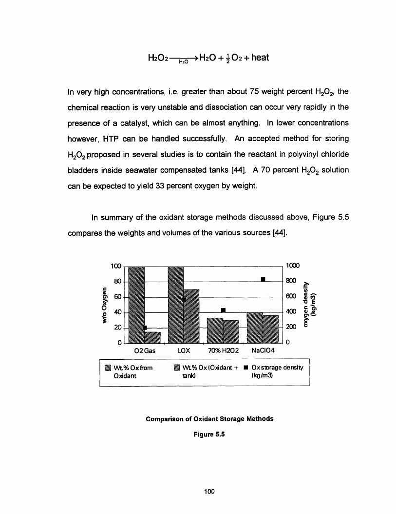
H202 H20 + '02 + heatHzO 2~~~
In very high concentrations, i.e. greater than about 75 weight percent H202, the
chemical reaction is very unstable and dissociation can occur very rapidly in the
presence of a catalyst, which can be almost anything. In lower concentrations
however, HTP can be handled successfully. An accepted method for storing
H2 02 proposed in several studies is to contain the reactant in polyvinyl chloride
bladders inside seawater compensated tanks [44]. A 70 percent H2 02 solution
can be expected to yield 33 percent oxygen by weight.
In summary of the oxidant storage methods discussed above, Figure 5.5
compares the weights and volumes of the various sources [44].
l f"nIsw
80
cm 60
° 40
20
0
E
02Gas LOX 70% H202
1000
800
600
400
200
0
Z.c _
E" 0)', coOWJ
0o
NaCI04
Wt.% Oxfrom [] Wt.%Ox(Oxidant + · Oxslorage densityOxdant lank) (kg/m3)
Ii
Comparison of Oxidant Storage Methods
Figure 5.5
100
wIe
5.3 WASTE PRODUCT MANAGEMENT
Almost as much of an issue as what fuels to use is how to deal with the
waste products of AIP. From a design view, management of the waste products
affects the net power output of the plant since energy will be required to return
the products to the sea or process them for retention onboard. Operationally,
exhaust products may leave a trail that while invisible to the eye, could be
detected by other sophisticated means.
Since energy conversion generally involves hydrogen consumption, any
fuel that brings with it other elements such as carbon will have waste products to
be processed, such as carbon dioxide. Some waste products are not really
waste like the pure water generated from the PEM cell which is potable and can
be easily stored for crew consumption or transferred to a variable ballast system
for discharge overboard. The aluminum-oxygen cell generates hydrargillite, but
as water and potassium hydroxide are added to the system to compensate for
the corrosion of the aluminum plates, this waste can be stored in the empty
reactant tanks for processing upon return to port. Thus the primary concern of
waste management is how to deal with carbon dioxide and other inert gasses.
In the torroidal oxygen storage design by Fincantieri of Italy, the concept
proposes compression and storage of the waste gas without discharging
overboard [29]. The other alternative is to discharge the gasses overboard.
After expending the energy to compress the gas to operating depth pressure (20
kW, based on PEM cell with reformed methanol at 500 kW and 1000 ft operating
depth, Appendix B), the gas must be diffused so that large bubbles don't trail the
submarine. One concept for distributing the gasses is shown in Figure 5.6 [22].
The most promising solution to the carbon dioxide discharge problem
comes from a consortium headed by Cosworth Engineering of the United
Kingdom. In this (Cosworth) system, exhaust gasses are scrubbed of carbon
101
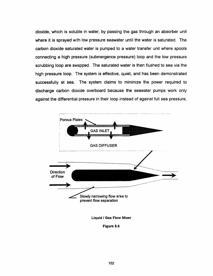
dioxide, which is soluble in water, by passing the gas through an absorber unit
where it is sprayed with low pressure seawater until the water is saturated. The
carbon dioxide saturated water is pumped to a water transfer unit where spools
connecting a high pressure (submergence pressure) loop and the low pressure
scrubbing loop are swapped. The saturated water is then flushed to sea via the
high pressure loop. The system is effective, quiet, and has been demonstrated
successfully at sea. The system claims to minimize the power required to
discharge carbon dioxide overboard because the seawater pumps work only
against the differential pressure in their loop instead of against full sea pressure,
Porous Plates .
GAS DIFFUSER
Directionof Flow
Slowly narrowing flow area toprevent flow separation
Liquid / Gas Flow Mixer
Figure 5.6
102
i
ON--
M.

requiring only 6 percent of the output power of the plant [65]. Using this
estimate, about 30 kW of power would be required to discharge carbon dioxide
overboard from a 500 kW PEM plant with reformed methanol.
The Cosworth system is being strongly considered by almost every nation
interested in processing carbon dioxide gas overboard.
ScrubbedExhaust as
Out , .
ENGINE W
ATMOSPHERE n,CYCLE O
In
CooledExhaust
In
LP Seawater.a
- U--- ------ - --
SEAWATERTRANSFER
SYSTEM
HP Seawater
IIAl li
I
i
r 'iriiL i
I
I
I
I
-I
Cosworth Exhaust Management System
Figure 5.7
103
Overboard
I
l _-
na�ssssssspsssssss�err' -Bslllllas�lllllss�lssllla��
I_ ,~~
v
I
!!1\! I

(Blank Reverse)
104

CHAPTER SIX
6.0 THE SUBMARINE MODEL
The modeling process for the weights and volumes which determine the
shape of the final submarine hull are described in this chapter. Section 6.1
describes the submarine envelope, while Sections 6.2 and 6.3 describe the
model for volumes and weights. Section 6.4 outlines the method for ship
powering and endurance calculations.
As stated in Chapter 2, the estimation of weights and volumes for a
submarine concept design come from an extensive historical data base. For this
thesis, the data base for weights and volumes is derived from a 1988
Massachusetts Institute of Technology (MIT) thesis by Stenard titled
"Comparative Naval Architecture of Modern Foreign Submarines" [61]. The
approach for the model is based on the MIT Math Model for Conventional
Submarines [53] (MIT Math Model) and several papers by Captain Jackson on
submarine parametrics and concept design [33, 34].
The AIP submarine model builds from a baseline diesel electric
submarine, which was originally synthesized using the MIT Math Model [68]. In
this design, a concept submarine, Appendix C, was developed using the math
model and balanced in sufficient detail to gain confidence in the model, evaluate
the validity of the various coefficients, and establish certain weights and volumes
for use in this thesis. This model therefore develops a "Hybrid" submarine, one
that retains full diesel electric capability and adds an AlP option, rather than one
that relies on AIP alone.
105

6.1 HULL ENVELOPE
It is well accepted that a streamlined form will offer less resistance to flow
than one that is irregular in shape. Because the modern submarine is optimized
to operate below the water surface rather than above as in pre-1960 designs,
the body of revolution or "Albacore" form has been adopted as the primary hull
shape. In describing its shape, Jackson states that an optimum design will have
"a well rounded nose and a streamlined tail with an UD (length to diameter) ratio
of about 6 and a maximum diameter about 40% aft of the forward end" [33].
It is seldom possible to achieve an optimum shape as the size of the hull
envelope is driven by the weight and volume of the equipment contained inside
the submarine and usually results in the addition of a section of hull, constant in
diameter, between the forward and after parabolic sections, Figure 6.1. The
Afterbody Parallel Midbody Forebody
The Submarine Envelope
Figure 6.1
106
-l
--
- - - | - l-

diameter is generally constrained by navigational restrictions imposed on the
beam and draft by the harbors where the ship is expected to operate. Thus an
envelope balance must be achieved which contains sufficient volume for the
ship, does not pose too wide a beam and is an acceptable compromise with
regards to L/D ratio. In addition to changing the length or diameter, the hull
shape can be made fuller of sleeker by varying certain constants which describe
the parabolas making up the bodies of revolution and can be used to adjust the
buoyancy contributed by the hull. Appendix D contains details of the hull
envelope model.
6.2 VOLUME ESTIMATES
The details of the volume estimates are contained in Appendix E.
6.2.1 PRESSURE HULL VOLUME
As shown in Figure 2.3, the volume inside the pressure hull (Vph) can be
broken into the following categories:
Mobility
Weapons
Command and Control (C3 1)
Ship Support (Auxiliaries, Habitability and Storerooms).
The size of each of these items is dependent on different aspects of the owner's
statement of requirements and are described below.
6.2.1.1 MOBILITY VOLUME
This volume describes that portion of the hull which involves propulsion
and power generation, to include tankage for any required fuel. For
107

conventional diesel electric submarines, the following relationship was
developed in the MIT Math Model
VDE = SHP(PDE),
where PDE represents the average mobility density. This relationship varies with
installed shaft horsepower which changes proportionately with ship size if the
required speed performance of the hull is fixed. For this model, the relationship
was modified to include terms which reflect the additional volume of the AIP
plant, i.e. energy converter, fuel storage, compensating water, product
management system, and any change in battery size from the baseline.
VAIP = SHP(PDE) + AVBat, + VAIP
6.2.1.2 WEAPONS and C31 VOLUME
The weapons volume is based on the amount of ordnance carried by the
submarine and the number of torpedo tubes, thus the value is fixed by owners
requirements and is unaffected by adding AIP capability.
VP = No. Torp. Tubes(pw) + No.Reloads(p,, )
The volume for C31 is likewise fixed by owners requirements and is a constant
based on volume estimates from ships with similar capabilities.
6.2.1.3 SHIP SUPPORT VOLUME
This volume is multifaceted and includes the remaining volume inside the
pressure hull, which is made up of berthing and messing facilities, storerooms,
office spaces and auxiliary machinery spaces. Berthing, messing and office
space are based on factors proportional to navy standards for crew size, while
108
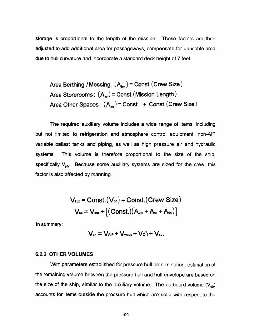
storage is proportional to the length of the mission. These factors are then
adjusted to add additional area for passageways, compensate for unusable area
due to hull curvature and incorporate a standard deck height of 7 feet.
Area Berthing / Messing: (Ab,,,) = Const. (Crew Size)
Area Storerooms: (Ar,) = Const. (Mission Length)
Area Other Spaces: (Ao,) = Const. + Const. (Crew Size)
The required auxiliary volume includes a wide range of items, including
but not limited to refrigeration and atmosphere control equipment, non-AlP
variable ballast tanks and piping, as well as high pressure air and hydraulic
systems. This volume is therefore proportional to the size of the ship,
specifically Vph. Because some auxiliary systems are sized for the crew, this
factor is also affected by manning.
Vau = Const.(Vph) + Const.(Crew Size)
Vss = Vaux + [(COnSt.)(Abm + Asr + Aos)]
In summary:
Vph = VAIP + Vweps + V 31+ Vss.
6.2.2 OTHER VOLUMES
With parameters established for pressure hull determination, estimation of
the remaining volume between the pressure hull and hull envelope are based on
the size of the ship, similar to the auxiliary volume. The outboard volume (Vob)
accounts for items outside the pressure hull which are solid with respect to the
109

sea in that they will not flood with water, such as high pressure air bottles and
structural members. Vob is proportional to Vph, and when added to Vph' the total is
termed the everbuoyant volume (Veb). The free flood volume (Vff) is the space
inside the envelope which floods on submerging, and from a naval architecture
viewpoint does not contribute to buoyancy when surfaced. Vff is proportional to
Veb. Both factors are based on historical data.
Vob = Const.(Vph)
Veb = Vob + Vph
Vff = Const.(Vph)
The remaining volume is allotted to reserve buoyancy and encompasses
the main ballast tanks. This volume is based on a percentage of the
everbuoyant volume, nominally 10 - 15 percent, and is set by the owners
requirements based on the expected mission of the submarine. When added to
the everbuoyant volume, main ballast tank volume adds up to the submerged
volume.
Vmbt = Const. (Veb)
Vsub = Veb + Vmbt
Verv = Vsub + Vif
6.3 WEIGHT ESTIMATES
The details of the weight estimates are contained in Appendix F.
110

6.3.1 SURFACED DISPLACEMENT
Similar to the pressure hull volume, the surfaced displacement, or normal
surfaced condition (NSC) is a summation point for the estimated weights in the
ship. Figure 2.3 listed seven weight groups that make up the NSC, however this
model combines some of the groups based on information which can be
estimated from Stenard.
6.3.1.1 STRUCTURAL WEIGHT
Structural weight includes the pressure hull itself, as well as the
scantlings necessary to provide the required hull stiffness. As a result, this
factor is proportional both to the final size of the ship as well as the diving depth,
which is set by the owner. Stenard gives the following relation for structural
weight:
Wr = {NSC[Const. (Diving Depth)+ Const.]}.
This weight is not directly affected by the addition of an AIP power plant.
6.3.1.2 MOBILITY WEIGHT
For diesel electric submarines, the following describes the relationship for
the weight of mobility:
Wmob = Battery Weight + Const.(SHP)0"4.
This relationship varies with the installed shaft horsepower and battery weight,
both of which will vary directly with ship size if the required speed performance
of the hull is fixed. Mobility weight is the one weight parameter which is directly
111
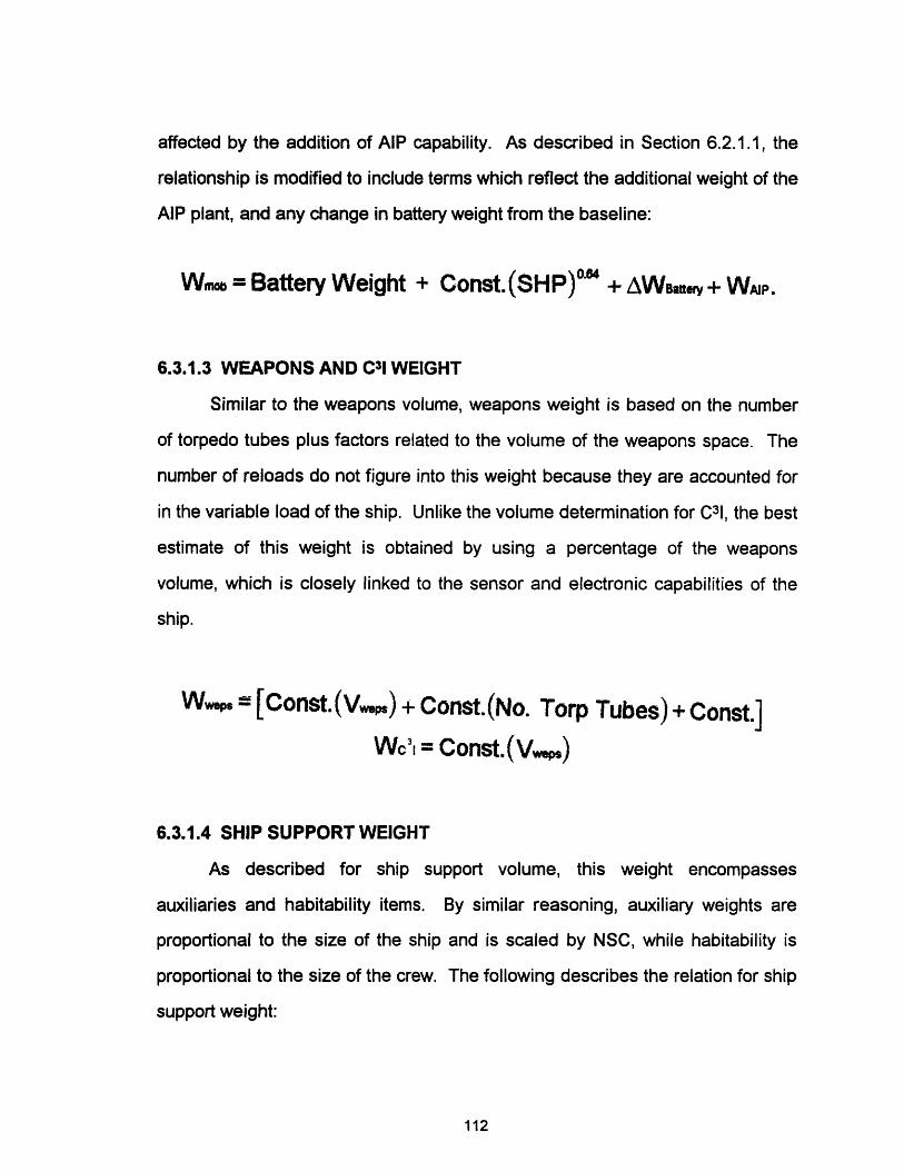
affected by the addition of AIP capability. As described in Section 6.2.1.1, the
relationship is modified to include terms which reflect the additional weight of the
AIP plant, and any change in battery weight from the baseline:
Wmb = Battery Weight + Const. (SHP)O'" + AWBterr + WAP.
6.3.1.3 WEAPONS AND C31 WEIGHT
Similar to the weapons volume, weapons weight is based on the number
of torpedo tubes plus factors related to the volume of the weapons space. The
number of reloads do not figure into this weight because they are accounted for
in the variable load of the ship. Unlike the volume determination for C31, the best
estimate of this weight is obtained by using a percentage of the weapons
volume, which is closely linked to the sensor and electronic capabilities of the
ship.
Wweps [Const.(V,,) + Const.(No. Torp Tubes) + Const.]
Wc' = Const.(V_.)
6.3.1.4 SHIP SUPPORT WEIGHT
As described for ship support volume, this weight encompasses
auxiliaries and habitability items. By similar reasoning, auxiliary weights are
proportional to the size of the ship and is scaled by NSC, while habitability is
proportional to the size of the crew. The following describes the relation for ship
support weight:
112
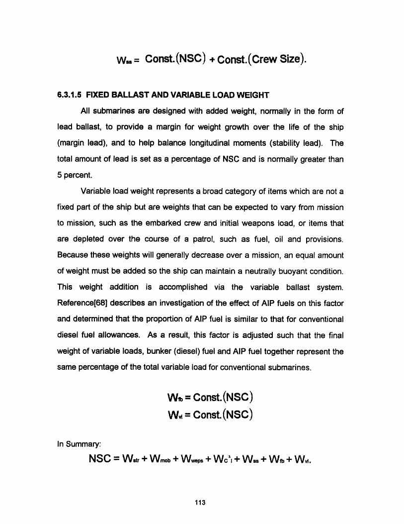
W = Const.(NSC) + Const.(Crew Size).
6.3.1.5 FIXED BALLAST AND VARIABLE LOAD WEIGHT
All submarines are designed with added weight, normally in the form of
lead ballast, to provide a margin for weight growth over the life of the ship
(margin lead), and to help balance longitudinal moments (stability lead). The
total amount of lead is set as a percentage of NSC and is normally greater than
5 percent.
Variable load weight represents a broad category of items which are not a
fixed part of the ship but are weights that can be expected to vary from mission
to mission, such as the embarked crew and initial weapons load, or items that
are depleted over the course of a patrol, such as fuel, oil and provisions.
Because these weights will generally decrease over a mission, an equal amount
of weight must be added so the ship can maintain a neutrally buoyant condition.
This weight addition is accomplished via the variable ballast system.
Reference[68] describes an investigation of the effect of AIP fuels on this factor
and determined that the proportion of AIP fuel is similar to that for conventional
diesel fuel allowances. As a result, this factor is adjusted such that the final
weight of variable loads, bunker (diesel) fuel and AIP fuel together represent the
same percentage of the total variable load for conventional submarines.
Wo = Const.(NSC)
W = Const.(NSC)
In Summary:
NSC = Wstr + Wmob + Wweps + Wc'3 + Wss + Wfb + W,.
113

By solving the above equation for NSC, the total weight to be supported
by displaced water at all times is determined and must be equated to the
everbuoyant volume determined earlier. This balance is achieved by increasing
the fixed ballast percentage if the equivalent weight of the displaced seawater
volume is greater than NSC (volume limited). If the estimated ship weight is
greater than the equivalent displaced seawater volume weight, the dimensions
of the hull envelope are increased, which will proportionately increase the
everbuoyant volume until the two values match (weight limited).
6.4 POWERING AND ENDURANCE
Once the initial estimates of weight and volume are made, a check must
be made to see if sufficient allowance has been made for required propulsion
and electrical hotel loads, as well as endurance requirements. This section
describes the method used to model these estimates. The details for this
section can be found in Appendix G.
6.4.1 POWERING
6.4.1.1 HYDRODYNAMICS
While the Albacore style hull helps to reduce resistance, a certain amount
of resistance must be overcome to push the hull form through the water. This
resistance can be divided into two broad categories: hull resistance and
appendage resistance.
Hull resistance has three component parts:
114
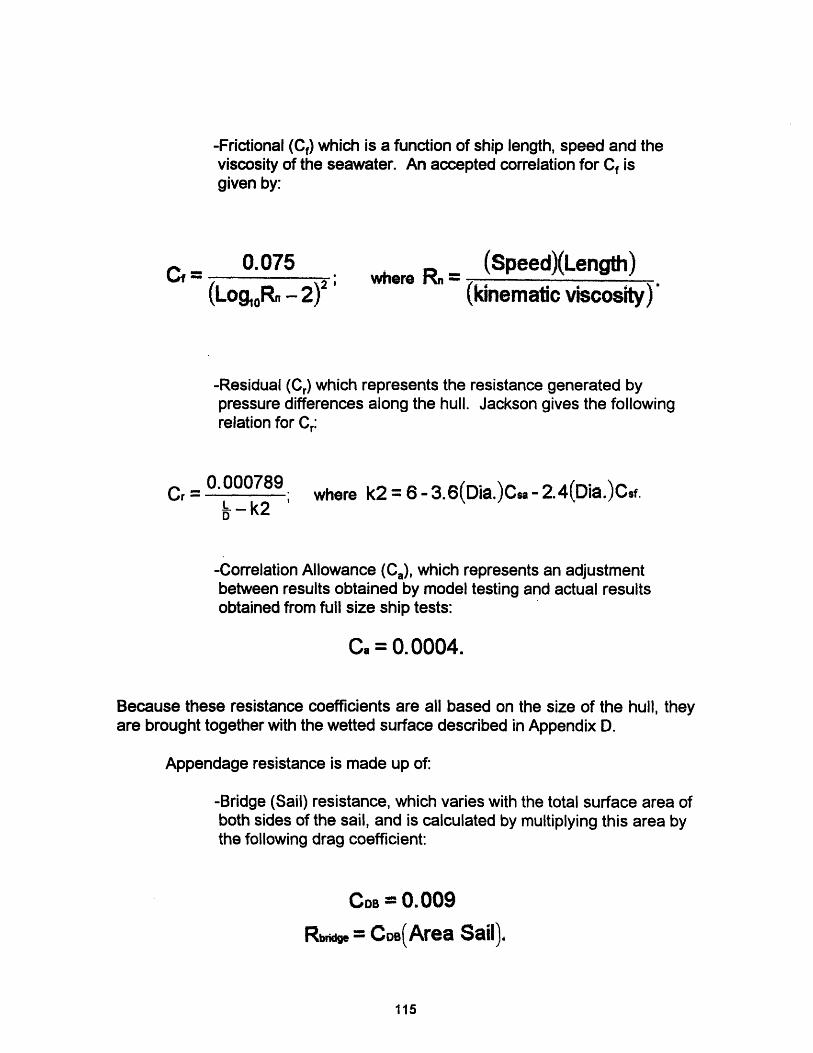
-Frictional (Ca) which is a function of ship length, speed and theviscosity of the seawater. An accepted correlation for C isgiven by:
0.075
(Log0Rn - 2)2 ;where Rn =
(Speed)(Length)
(kinematic viscosity)
-Residual (C,) which represents the resistance generated bypressure differences along the hull. Jackson gives the followingrelation for Cr:
0.000789Cr =
L -k2D
where k2 = 6- 3.6(Dia.)Csa - 2.4(Dia.)Csf.
-Correlation Allowance (Ca), which represents an adjustmentbetween results obtained by model testing and actual resultsobtained from full size ship tests:
Ca = 0. 0004.
Because these resistance coefficients are all based on the size of the hull, theyare brought together with the wetted surface described in Appendix D.
Appendage resistance is made up of:
-Bridge (Sail) resistance, which varies with the total surface area ofboth sides of the sail, and is calculated by multiplying this area bythe following drag coefficient:
CDB = 0.009
R, = CDB(Area Sail).
115
C -=

-Appendage resistance varies with the total surface area of thecontrol surfaces; bow planes, stern planes and rudder. Jacksonhas shown that for good existing submarine designs, thisresistance can be approximated by:
Rapp.= (Length)(Diameter)1000
With an estimate of the total resistance on the ship, the effective horsepower
(EHP), which is the power necessary to push the hull through the water, can be
calculated by the following:
EHP = Const. (Speed)3[WS(Cf + Cr + Ca) + Rbridge + Rappend.].
EHP is translated into shaft horsepower (SHP) through the propulsive
coefficient (PC):
EHPSHPPC
PC represents the efficiency of the propeller in transferring the power at the
propeller to the ocean, and is a function the open water characteristics of the
propeller (o), the hull efficiency (h ), the relative rotative efficiency ( rr) which
accounts for turbulence in the wake in the vicinity of the propeller:
PC = ( o)(hX)(7,
For this model, the PC determined for a seven bladed, 15.5 ft diameter fixed
pitch propeller in Reference [68] is assumed. Any comparisons made in the
116

model with various propeller options are accomplished by adjusting the value for
PC.
6.4.1.2 PROPULSION MOTOR TURNDOWN
The propulsion motor installed in any shipboard application must be sized
to meet high end power requirements. However in the case of AIP applications,
the motor will be operated at a power much less than its rated value. Operation
at this lower power may result in a lower motor efficiency and a lower overall
transmission efficiency for the conversion of electrical power to shaft
horsepower.
Conventional DC motors are presently installed in many diesel electric
submarines. Short of utilizing Permanent Magnet AC motor technology, Section
3.1.2, AC synchronous motors employing power electronics technology are
available now for use in propulsion applications. These motors do not suffer
from the same efficiency loss as conventinal DC motors [45]. For this model,
motor efficiency was assumed to be constant over the range of operation.
6.4.2 SNORKELING POWER AND BUNKER FUEL CALCULATION
This power represents the additional resistance on the hull due to
wave/hull interactions near the surface while operating submerged with the
snorkel mast extended. The real effect on the ship is that more power is
required while at periscope depth to maintain a given speed. The additional
power is given by
SHPwave= Const.(WS)(C ); where Cwa Con---_t.
117

and is used to determine the amount of bunker fuel required for the ship to make
the stated diesel endurance. The weight of bunker fuel is given by the following
relationship which combines range, diesel engine economy and total engine
load:
(Range)(sfc)[(SHPwae + sub.) + 1. 34(HOTEL LOADDE)]Fuel(Itons) 2240(tailpipe)( r )(Snorkel Speed)
6.4.3 HOTEL LOADS
Hotel loads represent all the parasitic electrical loads on the ship which
are required to support essential ship functions. Traditionally, diesel submarine
hotel loads are smaller than on nuclear submarines because electrical power is
a premium, coming directly from the battery while submerged. AIP really does
little to alleviate the problem completely because at low speeds, the electrical
hotel load is predicted to be several times larger than that required for
propulsion. Stenard gives the following relation for calculating hotel load:
HOTELDE (kW) = 1. 5(VmOb) + 4(Vc') + 1.5(Vss) + VwEps1000
Hotel load is a function of various ship volumes which grow as ship size
increases. While its absolute size is small, the factor of four applied to the
volume for C31 reflects the intensive power nature of electronic equipment.
Since hotel load scales with submarine size, no adjustment was made for the
AIP plant itself, however a constant value of 15 kW was added to account for the
power necessary to operate one CO-H2 burner and one CO2 scrubber for
118

atmosphere control, equipment not normally found on diesel-electric
submarines.
HOTELAIP = HOTELDE + 15kW
Some additional relief that AIP may provide on hotel load comes from the pure
water generated by some fuel cell plants, or the potential for bottoming cycles or
other use of waste heat, eliminating some electrical heating requirements. None
of these considerations are incorporated in this model.
6.4.4 BATTERY ENDURANCE
AlP can provide relatively low power, 500 kW, for significant periods of
time (weeks). AlP cannot provide the power, 4000-5000 kW, necessary for high
speed bursts for any period of time. The solution to this short term, high power
problem is the storage battery, which can provide the burst energy necessary to
make high speeds for several hours at a time. Thus the battery endurance at a
given speed is an important quantity to evaluate for any AIP model. The general
relationship for battery endurance is given by:
(Batt. Size)(Batt. Capacity)(,,)( ,,)Batt. Endur. (hrs)[(0.746 * SHP) + HOTEL LOADAIP]
In this relationship, battery capacity is the kW rating for the battery at a
particular discharge rate, assumed to be about 2 hours for burst conditions and
80+ hours for creep calculations. For any periods of time estimated to be
greater that these two assumptions, i.e. a burst period estimated as 2.5 hours,
the results are conservative, as a battery will generally deliver more total energy
when discharged at a slower rate. 7coul represents the efficiency associated
119

with recovering energy stored in the battery. In this model, any battery can be
represented as long as the rapid and slow discharge rates are known and an
estimate of 7/coul made.
This same relationship in a different form is used to calculate any change
in battery weight and volume from the baseline submarine. For a given
endurance period, the required battery size can be determined. The difference
in the number of batteries from the baseline is then determined and using weight
and volume estimates for a standard battery, a change in battery weight and
volume can be calculated and applied to the mobility estimate for the ship.
6.5 THE AIP PLANT
The AIP plant is modeled using the data presented in Appendices A and
B for the various plant and reactant options. For a generic AIP plant, the
following component parts were considered:
-Plant type (PEM, CCD, etc.)
-Reformer required (YES, NO)
-Oxidant type (LOX, H2 02, etc.)
-Fuel type (H2, Diesel, Methanol, etc.)
-Other fluid (KOH/VATER, ARGON, Comp Water)
-Product mgmt. system (YES, NO)
-Breathing oxygen (YES, NO. Req'd if LOX not designated
as the choice for oxidant)
For each item, a weight (g or kg ) or volume ( or k-hr) factor as
appropriate was determined so that an estimate of the total weight and volume of
that part could be made. The parts that are applicable to a given plant are then
summed to give a total AIP weight and volume. These values are then input to
the weight and volume relations for mobility to give total AIP capable values.
120

CHAPTER SEVEN
7.0 COMPUTER CODE DEVELOPMENT
The computer code for this model was written using Turbo C++, Version
3.0 for DOS by Borland, incorporating the submarine model concepts presented
in Chapter Six.
Figure 7.1 provides an overview of the code, titled "SUBSIZE", showing
the flow path through the functions to achieve a balanced design. Input data in
file SUBSIZE.CPP is modified by the user before each run to establish the
desired ship constraints. The AIP plant is defined in file AIPSIZE.CPP for one of
six different AlP plant options.
The computer code, including the main program, functions, input data and
sample output is contained in Appendix I.
7.1 OVERVIEW
Referring to figure 7.1, the user selects the desired parameters for the
ship in the main program, SUBSIZE.CPP. The first functions called estimates
the volumes and then the required hull envelope. Weights are estimated next,
since some weight estimates are based on the volumes already determined.
Weights and volumes are then matched in a looping process which checks the
value of NSC against a displacement equivalent to Veb:
VebAV = -.
35
NSC and Av, are matched by the following process:
121

INPUT DATASUBSE .CPP
ESTIMATE WEIGHTSWEIGHT ()
I
I I
+
BALANCE
WEIGHT LIMITEDWT_LIMIT ()
t-
I I
+
VOLUME LIMITEDVL_LIMIT ()~~~~~~~.,
I "- SELECT AIP PLANT
ESTIMATE POWER
CALC. SNORT POWER/FUEL I
CALC. HOTEL LOAD I
CALC. BATTERY SIZE I
CALC. BATT. ENDR. / INDESC. RATIO
CALC. AIP PLANT SIZEII- I
POWER ()
SNORT ()DIESFUEL ()
HOTEL ()
BATTDELT ()
BATTENDR ()INDESCR ()
AIPSIZ ()
"SUBSIZE" Flowchart
Figure 7.1
122
ESTIMATE VOLUMESVOLUME ( )
DETERMINE ENVELOPEENVLEOPE ()
--
-~~~~~
mmomm
I I

WEIGHT LIMITED
(NSC > Av,)
The overall length of the hullenvelope is increased in 0.1 footincrements until the resultingenvelope displaces enough water toequal NSC. Volumes are thenrecomputed.
VOLUME LIMITED
(NSC < Av.)
The amount of lead is increased byadjusting the lead margin inincrements of 0.04 percent(approximately 100 Itons) until NSCequals Av.. Weights are thenrecalculated.
The weights and volumes are matched in this fashion, rather than refining
the estimates of weights or volumes, because in this first look at a concept
design, not enough information is usually available to adjust weights and
volumes. Only after a complete trip around the design spiral can such
adjustments be made.
With a balance achieved between weights and volumes, the estimates for
ship power, fuel load, hotel load, and battery endurance and indiscretion ratio
are made. These parameters are calculated first because they will be used to
provide the estimate of the size of the AIP plant and its required fuel, as well as
any increase in the size of the battery. With the power requirements
established, the size of the particular AIP plant is calculated and an adjustment
in the size of the battery estimated. These values are then added to the weights
and volumes for mobility which will typically increase these values.
Now that the estimates for weight and volume have changed, the program
enters an iterative loop where the process described above is repeated. Each
time through, new values for ship powering, hotel load and battery endurance
and indiscretion ratio are calculated because as the ship changes in size, so will
123

these values. At the end of each loop, a revised total AIP plant size is
determined along with a revised change in battery size. These new values then
replace the previous values in the mobility weight and volume estimates.
Iterations are continued until the change in NSC from one iteration to the next is
less than one percent.
Program output includes a restatement of the key input parameters as
well as those parameters which were calculated or adjusted by the program such
as lead margin. The output also summarizes the volume and weight estimates
for the submarine hull, as well as weight and volume estimates for the AIP plant,
broken down by plant, reactants and auxiliaries.
A sample program output sheet is contained in Appendix I.
124
CHAPTER EIGHT
8.0 RESULTS AND CONCLUSIONS
The goal of this thesis was to develop a computer code to evaluate
various AIP propulsion options by synthesizing a submarine hull according to
certain owners requirements for mission capability and performance. This code
can be used to support the concept design of AIP submarines.
The model developed gives good results when compared to other studies
of AIP submarines. Validation of the model is addressed in Section 8.1 with AIP
and other technological impacts evaluated in section 8.2. Section 8.3 illustrates
the usefulness of the tool in performing trade-off studies as a part of the
submarine design process.
8.1 MODEL VALIDATION
It is difficult to measure the accuracy of this model against real world
submarines for several reasons. The number of true non-nuclear AIP
submarines is small, and many of the technologies evaluated in this thesis are
still theoretical in terms of full scale applications. Additionally, the details of any
real or proposed ships are carefully guarded by the respective consortiums and
governments conducting AIP investigations.
The AIP option has been investigated by several student submarine
design teams in the Naval Construction and Engineering Program at the
Massachusetts Institute of Technology (MIT) in a variety of scenarios and
missions, but AIP has always fallen short in trade-off studies when compared to
nuclear power and total ship performance. One recent study at MIT evaluated
the AIP option from the perspective that AIP was the only option for extending
125

underwater endurance, forcing an detailed evaluation of AIP concerns and
limitations [60]. This study evaluated PEM fuel cell with methanol and Aluminum
Oxygen semi-cell technologies, selecting one option for a concept design. In the
concept design, a detailed evaluation of discrete submarine weights and
volumes and arrangements was made to validate the approach used and to
verify the appropriateness of the margins assumed. The approach to submarine
synthesis used in that study was paralleled by this thesis with results presented
in Figure 8.1.
AC
U,z
5000
4000
3000
2000
1000
0BASE
.
LINE PEM- 25day
endurance
PEM- 35day
endurance
ALOX- 25day
endurance
ALOX- 35day
endurance
--- CANADIAN HYBRID AIP ... -- - SUBSIZE COMPUTERSUBMARINE MODEL
Comparison of Canadian Hybrid Submarine and SUBSIZE results
Figure 8.1
As can be seen, the results of the SUBSIZE model for NSC closely follow
the findings from the Canadian submarine study. While the same margins and
scaling factors used in the study were duplicated in the computer model,
126

detailed design decisions in the Canadian submarine study had a significant
impact on the final results for each variant. Detailed decisions of this sort were
not included in the SUBSIZE model results.
8.2 GENERAL RESULTS
For many of the figures presented, results are compared by NSC between
variants. This attribute was chosen for comparison purposes because it
represents the balancing point in the model between weights and volumes. NSC
also has a significant impact on other attributes such as installed SHP and AIP
plant capacity.
Results showed each of the AIP options to be volume limited, requiring
the model to add lead ballast by increasing the lead margin to achieve a
balanced design. This is attributed to the fact that the overall AIP plant has an
average density less than that of seawater (64 Ibs/ft3), Table 8.1.
Table 8.1Comparison of AIP Plant Densities
**25 day endurance, 8 kt AIP speed, 20 kt burst speed.
127
AIP Plant AIP Weight AIP Volume Plant Density
(Itons) (ft3 ) (Ib/ft3)
Aluminum 476.99 25,627.63 41.69
CBC 500.47 46,841.82 23.93
CCD 744.34 67,824.4 24.58
MCFC 252.4 22,991.55 24.50
PEM 278.12 23,323.5 26.71
Stirling 699.11 64,831.88 24.15
Supporting data for each of the figures in this chapter can be found in
Appendix H.
8.2.1 OVERALL AIP IMPACT
Many investigations have been conducted regarding the benefits and
limitations of different AlP options. It is not unexpected that the results obtained
with the SUBSIZE model should parallel results obtained by others. Figure 8.2
presents the results by AlP plant for various ship and AlP attributes and shows
that the MCFC plant results in the smallest ship for a common set of
requirements. The PEM plant is closely matched, and given the shipboard
suitability issues and operating experience for each plant, it can be understood
why the PEM fuel is being actively pursued by many nations. The CCD engine
is predicted to require the largest ship size of the three heat engines evaluated
due to its generally higher specific plant weight and high specific reactant
consumption rates, Table A.1. Despite these results, the CCD is a popular
option because diesel technology is readily available. The Aluminum Oxygen
plant ranked midway between the fuel cells and heat engines.
When the AlP endurance is varied as in Figure 8.3, the impact on ship
size shows that the variance in ship weight is larger for those plants whose
specific reactant consumption rates are higher, specifically the heat engine
plants. The trends observed in Figure 8.3 are consistent with those presented in
reference [52].
128

,-~~~~ X A
- -.. ,. - -
c4~~~~~~~~ a, ,m
%,·~~~~~~~~~~~~~ "~
ALOX CBC CCD MCFC PEM STRLNG
8 kt AIP speed, 20 kt burst speed, 25 day AP endurance with LOX
- e - · LENGTH - - NSC - - - SIZE AIP[ft/1,000] [io3ns/10,000] [kW/1,000]
Comparison of AIP Plants
Figure 8.2
12000
10000
8000
6000
4000
CBC CCD MCFC PEM STRLNG
8 kt AIP speed, 20 kt burst speed with LOX
-- e-- 25 Days 30 Days - - - 35 Days
AIP Plant Variation with Endurance
Figure 8.3
129
0.6
0.5
0.4
0.3
0.2
0.1
0
0co
0-U,z)z
2000
0ALOX
8.2.2 IMPACT OF REACTANTS
Figures 8.4 and 8.5 show the effect of various reactant storage methods
on NSC. For comparison purposes, the PEM plant with methanol was chosen
for the oxidant storage variation and the PEM plant with LOX chosen for the fuel
storage variation. All other attributes for the ships were held constant.
Of the four oxidant storage methods evaluated, LOX, HTP and sodium
perchlorate all have a similar impact on ship size, while gaseous storage
methods compare poorly. These results are generally in agreement with figure
5.5, except that sodium perchlorate does not show the expected advantage in
terms of oxygen density. Gaseous storage is the worst because of the large
weight of the oxygen flasks compared to oxygen, Table B.1, with the internal
storage option suffering significantly because of the increased volume packing
factor. While competitive with LOX, HTP suffers from a history of mishaps and
difficulty in handling and will no doubt face significant opposition. The use of
sodium perchlorate in this size application may also be met with some
skepticism.
Figure 8.5 presents the results for various hydrogen storage options and
compares well to the trends of Figure 5.2. Next to methanol, liquid hydrogen has
the least impact on ship size, but presents many practical engineering issues in
its implementation. Metal hydrides enjoy great volume efficiency, but pay a
significant penalty in weight, forcing ship size to grow significantly to carry the
high weight of the hydride bed. Gaseous hydrogen storage is shown to be
beyond the realm of practicality as expected, due to the very low ratio of stored
hydrogen weight to that of it's vessel.
130
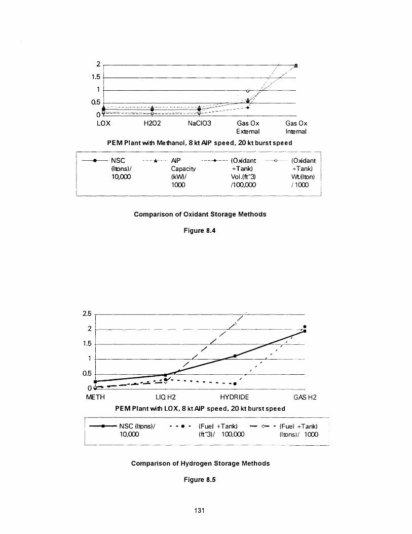
2 1 -I -,.1.5' "/ .1
0.5 . -'
O '.,_ --'-- ---- -'-- .......- ------ ------ . . .LOX H202 NaCIO3 Gas Ox
ExternalGas OxInternal
PEM Plant with Methanol, 8 ktAIP speed, 20 kt burst speed
*--- NSC ------A--- AP ------- (Oxidant .---.> ...- (Oxidant(ItDns)/ Capacity +Tank) +Tank)10,000 (kW)/ Vol.(ft^3) Wt(lton)
1000 /100,000 11000
Comparison of Oxidant Storage Methods
Figure 8.4
LIQ H2 HYDRIDE GAS H2
PEM Plant with LOX, 8 ktAIP speed, 20 kt burst speed
I- NSC (ItDns)/ - - (Fuel +Tank) - -- - (Fuel +Tank)10,000 (ft^3)/ 100,000 (Itons)/ 1000t~~~~~~~~~~~~~~~~~~~~~~~~~
Comparison of Hydrogen Storage Methods
Figure 8.5
131
2.5
2
1.5
1
0.5
0METH

8.2.3 IMPACT OF OTHER TECHNOLOGIES
Because the model considers the impact of AIP on the total submarine
design, certain ship constraints can often mask expected results. This concept
is evident in the comparison of battery types on ship size. In the model, battery
size is constrained to satisfy endurance requirements at both creep speed (90
hours) and at burst speed (2 hours). The general trend through all results shows
that the creep requirement is limiting. In Figure 8.6, the use of a LAIS battery,
which is assumed to have the same discharge characteristics as the lead acid
battery but a higher energy density, results in a smaller ship, while the Ni/Cd
option, which has an energy density between the two does not follow the same
trend. This difference can be explained by the relatively flat discharge curve for
Ni/Cd batteries over a range of discharge rates, Figure 4.9, which results is a
slightly larger installed battery and significantly more burst endurance.
1
0.8
0.6
0.4 - .
0.2-
0Lead Acid Ni/Cd LAIS
PEM Plant 4 kt creep speed, 20 kt burst speed
I- - - NSC (llns/ 10,000) for creep - - - Burst Endurance (hours/ 10)endurance of 90 hours for creep endurance of 90
hours
Comparison of Battery Options with Fixed Creep Endurance Requirement
Figure 8.6
132
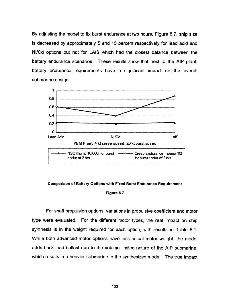
By adjusting the model to fix burst endurance at two hours, Figure 8.7, ship size
is decreased by approximately 5 and 15 percent respectively for lead acid and
Ni/Cd options but not for LAIS which had the closest balance between the
battery endurance scenarios. These results show that next to the AIP plant,
battery endurance requirements have a significant impact on the overall
submarine design.
1
0.8
0.6
0.4
0.2
0Lead Acid Ni/Cd LAJS
PEM Plant 4 kt creep speed, 20 kt burst speed
NSC (lions/ 10,000) for burst ~ Creep Endurance (hours/ 10)endur of 2 hrs for burst endur of 2 hrs
Comparison of Battery Options with Fixed Burst Endurance Requirement
Figure 8.7
For shaft propulsion options, variations in propulsive coefficient and motor
type were evaluated. For the different motor types, the real impact on ship
synthesis is in the weight required for each option, with results in Table 8.1.
While both advanced motor options have less actual motor weight, the model
adds back lead ballast due to the volume limited nature of the AlP submarine,
which results in a heavier submarine in the synthesized model. The true impact
133

Table 8.2
Effect of Propulsion Motor Type on NSC**
Motor Type NSC (Itons) Final Lead Margin
Conventional 2564.36 0.112
Permanent Magnet AC 2663.92 0.147
Superconducting 2660.67 0.137Homopolar DC*25 day endurance, 8 kt AIP speed, 20 kt burst speed
of this weight reduction would have to be evaluated in detail when the first
reconciliation of weights is done in the concept design process.
In varying the propulsor type, an improvement in propulsive coefficient is
evident in smaller plant sizes and fuel volumes. Figure 8.8 shows the results of
increasing the propulsive coefficient by 10 percent. As before for varied
endurance, the reduction in NSC is more significant for ships with higher specific
reactant consumptions.
0
U,z
5000
4000
3000
2000
1000
0AL
. A,.. A, ,
,=7- - T~~~~~~~~~~~~~~~~~:
.Ox CBC CCD MCFC PEM
25 day endurance, 8 ktAIP speed, 20 kt burst speed
STRLNG
.... A--- Fixed Pilch Prop. PC =0.86 - - Conta Rotatng PC =0.96
Effect of Propulsive Coefficient on NSC
Figure 8.8
134
I
I

8.3 SHIP TRADE-OFFS
As explained in Chapter 2, the design process is iterative, with many
trade-offs and compromises conducted to achieve a balanced design which
meets the owners requirements. The usefulness of the SUBSIZE model is
illustrated here with several examples which show how varying certain
requirements can affect the ship design.
Chapter 6 showed how decreasing the length to diameter (L/D) ratio can
improve the powering of the submarine, which results in a reduction in installed
SHP. Figure 8.9 illustrates the effect of increasing the hull diameter for one of
the larger AIP variants, with its resulting decrease in NSC and SHP.
1.40
1.20 =.
1.00-
0.80 --0.60 --- --= .0.40
30 31 32 33 34 35 36 37 38 39 40
Hull Diameter (feet)
---- NSC (I1Dns)/ - - - LOD/10 -- - SHP/10,00010,000
Effect of L/D ratio on NSC and SHP
Figure 8.9
The effect of increasing the desired AIP speed is shown in Figure 8.10.
While this curve is similar to the trend for increasing AIP endurance, the point
where increasing AIP speed has a significant impact on NSC is instructive. A
135

curve of this type tells the designer that a change in AIP speed of 1 knot below a
threshold of about 7 knots is relatively insignificant when compared to a similar 1
knot increase in speed above 7 knots.
0.8
0.6
0.4
0.2
0
..c~~~~~.. .'
I. , . .''
."
d~
4 5 6 7 8 9 10
AIP Speed (knots)
i - NSC --*---- AP A-....-- AAIPWt ---- AP (Ions/ Power (Iions/ Volume10,000) (kW/ 1000) (ft^3/
1000) 100,000)
Effect of AIP Speed on NSC
Figure 8.10
One final operational parameter considered important for submarine
operations is the indiscretion ratio, which is the amount of time spent snorkeling
to recharge batteries divided by the total time for a charge-discharge cycle.
While on AIP, this ratio will be essentially zero, however while transiting, this
ratio may be significant. The goal of reduced intersection ratio must be
balanced by the owners requirement to maintain an acceptable average speed
of advance when transiting. Table 8.3 shows how SUBSIZE may be used to
evaluate the effect of various transit and snorting speeds on indiscretion ratio
and speed of advance.
136

Table 8.3Indescretion Ratio and Speed of Advance
3 Knot Snort SpeedTransit Charge Speed of
3 Endurance! Time AdvanceRatio
(hours) (hours) (i knots)8 0.1 40.02 4.75 7.319 0.13 32.14 4.75 j 8.0110 0.15 25.84 4.75 1 8.6311 0.18 20,88 4.75 1 9.1612 0.21 16.99 ' 4.75 i 9.59
13 0.24 13.94 4.75 i 9.9314.~:: 3:~i?;=i:: ~: ;0.27 1017........17
4, not Snort Speed
Transit Charge I Speed ofIndesc.4 R Endurance Time Advance
(hours) (hours) (knots)8 0.10 40.02 4.79 7.419 0.13 32.14 4.79 8.1310 0.15 25.84 4.79 8.7811 0.18 20.88 4.79 9.3312 0.21 16.99 4.79 9.79
13 1 .94 4. -79.:: 10.16
::;:15; .:. ...- .4J9 10.61
5 not Snort Speed
Indesc. Transit Charge i Speed of5 Endurance Time Advance
(hours) (hours) (knots)8 0.11 40.02 4.85 7.519 0.13 32.14 4.85 8.2510 0.15 25.84 4.85 8.9211 0.18 20.88 4.85 9.50.t2:: i:i1-:. 0; 217 ::-::::;16:; ;! 1 4 :85 -9.99
"13 0.25 . '-:1394.-:. ; 4.85|. 10.3814 0.28 11.5 8; 10.68
16;:~ : 0.:35.?; .:. 8.1!;1; |!?.. 4.85..- 11.036 not Snort Speed
Transit Charge Speed ofIndesc.6 Ratio Endurance. Time Advance
(hours) (hours) (knots)8 0.11 40.02 4.95 7.619 0.13 32.14 4.95 8.3710 0.16 25.84 4.95 9.0611 0.18 20.88 4.95 9.67
ti .°. . 1 ;,. -;.'.~i ! .. : 9 : -. :!6' 18
0. 11: 5 10.9415. 032: . 9.63:: 4.95 11.18
':"-- 03.5:i : 81 1 i ! 4.95 I 11.34
137

(Blank Reverse)
138

CHAPTER NINE
9.0 AREAS FOR FUTURE STUDY
Beyond the effort here to model the AIP submarine, further study in the
area of AIP submarine design is warranted. Two possible areas for future study
include:
SUBMARINE COST
SUBSIZE does not attempt to answer the question of cost of construction.
The cost to build a submarine is well documented, but in the United States is
based on nuclear submarine data, and is compounded by the desire by private
shipbuilders to hold this type of data closely. As with the estimated parameters
for the AlP plants, there are no operational units in production, thus the true cost
of the AIP option is currently very difficult to estimate.
DETAILED POWER PLANT DESIGN
SUBSIZE assumes that an AIP plant will follow the same rules for
arrangements as the conventional submarines used in its database. This
assumption may not be strictly true since these plants bring with them
components such as closed cycle gas turbines, LOX tanks and fuel tanks with
bladders, components not presently found, if at all, on many submarines. Once
more detailed plant data is made available, an effort to arrange several AIP
propulsion plants would be instructive in refining the estimates of this model.
139

(Blank Reverse)
140

REFERENCES
1 Adams, V. W., Possible Future Propulsion Systems for Submarines, Journal of NavalEnaineerina, Vol. 31, No. 2, 1988.
2 Air Independent (Non-Nuclear) Propulsion (U), Anon., Office of the Chief of NavalResearch, Arlington, VA., July 1991.
3 Amphlett, J. C., Methanol, Diesel Oil and Ethanol as Liquid Sources of Hydrogen forPEM Fuel Cells, Proceedings of the 28th Intersociety Energy ConversionEngineering Conference, Vol.1, Atlanta, GA, 1993.
4 Anderson, E., Briefing notes, NAVSEA 03E2, November 1993.
5 ApDlication of Solid Oxide Fuel Cell (SOFC) Technoloav to Navy Propulsion and ShiDService Systems, Briefing Notes, February 1993.
6 Bagley,D., et al., "Integrated Electric Propulsion System for Minimum SignaturesSubmarine Technology Illustrative Concept"', (unpublished paper).
7 Blackburn, C. M., et al, "Cryogenic Storage of Submarine Breathing Oxygen: On-BoardDesign Concept', The Johns Hopkins University/Applied Physics Laboratory,Report # JHU/APL TG 1338A, August 1983.
8 Brenner, R., A Closed Cycle Diesel System for Submarines, Maritime Defence, Vol. 8,No. 5, June 1993.
9 Brooks, R. M., Brown, A. J., Class notes from Massachusetts Institute of TechnologyCourse 13.411: Methods of Ship System Design, Summer Term 1993.
10 Cervi, M., Personal communication, NSWC Annapolis, March 1994.
11 Clancy, T., SUBMARINE. A Guided Tour Inside a Nuclear Warship (New York: BerkleyBooks, 1993).
12 Carmichael, A. D., Submarine Propulsion Systems: An Evaluation of Air IndependentPropulsion Technologies, Massachusetts Institute of Technology, Department ofOcean Engineering Report 92-6, December 1992.
13 Clarkin, L., Adams, M. J., Canadian Second Generation AIP - A Formula for Success,Paper presented at The Royal Institute of Naval Architects InternationalSymposium on Naval Submarines 4, London, England, May 1993.
14 Corlett, R., Quarter of a Century of Modem Submarine Battery Technology, MaritimeDefence, Vol. 11, No. 3, March 1986.
15 Cortana Corporation, Anon., Air Independent Propulsion (AIP) Systems, 1988.
16 Dade, T. B., Advanced Electric Propulsion, Power Generation, and Power Distribution,Naval Engineers Journal, Vol. 106, No. 2, March 1994.
141

17 Dahlander, P., A Realistic Air Independent Propulsion System for Today and the NearFuture, Paper presented at the Royal Institute of Naval Architects InternationalSymposium on Naval Submarines 3, London, England, 1991.
18 Doerry, N., Briefing notes, NAVSEA 03R22, March 1994.
19 Dutton, J. L., Contrarotating Electric Drive for Attack Submarines, Naval EngineersJournal, Vol. 106, No. 2, March 1994.
20 Edman, U., CAPT, RSwN and Hagerstedt, A., CDR, FMV, The AIP Experience, theOperational Air Independent Propulsion in the Swedish Submarine NAECKEN.Background, Requirements, Performance, Installation and Results from TwoYears of Operational Service, Paper presented at The Royal Institute of NavalArchitects International Symposium on Naval Submarines 3, London, England,May 1991.
21 Energy Research Corporation, Anon., Phosphoric Acid Fuel Cell Power Source forSubmersibles, undated.
22 Fabris, G., Liquid/Gas Flow Mixers, NASA Tech Briefs, January 1994.
23 Foxwell, D., Staying Under Longer: The SSK Closes the Gap, Journal Article: sourceand date unknown.
24 Gibbons, D. W., Rudd, E. J., The Development of Aluminum/Air Batteries for PropulsionApplications, Proceedings of the 28th Intersociety Energy ConversionEngineering Conference, Vol.1, Atlanta, GA, 1993.
25 Grant, J.C., ed., Nickel-Cadmium Battery Application Engineering Handbook, GeneralElectric Company, 1975.
26 Harper, A. D., A New Approach to Air Independent Propulsion with CBC Engines, Paperpresented at INEC 92, Solutions to the Challenge of a New DefenceEnvironment, September 1992.
27 Heine, W., Mattheis, P, Reuter, K., Four-Circuit DC Motor for Submarine Propulsion,Reprinted Article from Siemens Power Engineering & Automation, Vol. VII,No. 2, March/April 1985.
28 Hensler, J. H., PEng, Mark Tinney, K, Submarine Propulsion: The Integrated ApproachIncluding AIP Systems, Paper presented at The Royal Institute of NavalArchitects International Symposium on Naval Submarines 4, London, England,May 1993.
29 Heemskerk, K.A., Air-independent Propulsion for Submarines: A Canadian Perspective,Maritime Engineering Journal, Canada, 1991.
30 Hellquist, K., Submarines with Air Independent Propulsion in the Present and FutureEnvironment, Paper presented at INEC 92, Solutions to the Challenge of a NewDefence Environment, September 1992.
31 Hereford, L. G., et al., Cryogenic Storage of Submarine Breathing Oxygen: PreliminarySafety and Hazard Analysis, Johns Hopkins University Applied PhysicsLaboratory, Report # JHU/APL TG 1338B, August 1983.
142

32 Heywood, J. B., Internal Combustion Enqine Fundamentals, (New York: McGraw-Hill,1988).
33 Jackson, H. A., CAPT., USN (Ret.), P. E., Submarine Parametrics, Paper presented atthe Royal Institute of Naval Architects International Symposium on NavalSubmarines, London, England, 1983.
34 Jackson, H. A., CAPT., USN (Ret.), P. E., Fundamentals of Submarine Concept Design,Paper presented at the annual meeting of the Society of Naval Architects andMarine Engineers, New York, 1992.
35 Kerros, P., Leroy, P., Grouset, D., MESMA: AIP System for Submarines, Paperpresented at the Royal Institute of Naval Architects International Symposium onNaval Submarines 4, London, England, 1993.
36 Knaack, I. K., Gruhl, E., Petersen, U. K., Advantages of Air-Independent PropulsionSystems for Submarines Being in Service. The German Approach, Paperpresented at the Royal Institute of Naval Architects International Symposium onNaval Submarines 3, London, England, 1991.
37 Kosek, J. A., et al, A Direct Methanol Oxidation Fuel Cell, Proceedings of the 28thIntersociety Energy Conversion Engineering Conference, Vol.1, Atlanta, GA,1993.
38 Kumm, W. H., Optimized Fuel Cell Propulsion for Submarines, Paper presented at theRoyal Institute of Naval Architects International Symposium on NavalSubmarines 3, London, England, 1991.
39 Laidley, R., Wagner, T., The Canadian Navy's Dilemma: Which Canadian AirIndependent Propulsion System is Batter - Aluminum/Air of Fuel Cells, Paperpresented at INEC 92, Solutions to the Challenge of a New DefenceEnvironment, September 1992.
40 Lusted, M., et al., Littoral Warfare Submarine, Design Project, Course 13.414, OceanEngineering Department, Massachusetts Institute of Technology, May 1994.
41 Maritime Defence, Anon., The Theory of the Lead Acid Battery, Vol. 13, No. 3,March 1988.
42 Maritime Defence, Anon., Bridging the diesel-electric/nuclear performance gap, Vol. 16,No. 4, April 1991.
43 Maritime Defence, Anon., Of Submarine Propulsion, Vol. 16, No. 4, April 1991.
44 Mart, P.L., Margeridis, J., Brighton, D. R., Fuel Cells for Submarine Air IndependentPropulsion, Materials Research Laboratory, Melbourne, Australia, 1990.
45 McCoy, et al., Olsen, E.,Reynerson, C., New Attack Submarine, Design Project, Course13.414, Ocean Engineering Department, Massachusetts Institute of Technology,May 1994.
143
46 McNair, E. J., Closed Cycle Diesel Engines for Underwater Power, Ship Department,Ministry of Defence, United Kingdom, date unknown.
47 McKee, L., "HYDROGEN PEROXIDE for PROPULSIVE POWER, Production and Useby the Germans During World War II", Presented at the Annual Meeting of theAmerican Society of Mechanical Engineers, New York, December 1946.
48 Mills, A. F., Heat Transfer, (Boston, MA, IRWIN, 1992)
49 Moore, C., Liquid Oxygen as an Oxidant for Underwater Vehicle Power, Paper presentedat INEC 92, Solutions to the Challenge of a New Defence Environment,September 1992.
50 Potter, . J., et al, Development of an IDI Diesel Engine Test Facility for Use with Non-Conventional Atmospheres, Proceedings of the 27th Intersociety EnergyConversion Engineering Conference, San Diego, California, 1992.
51 Prins, . C. A., Atmosphere-independent Propulsion for Diesel-electric Ocean-goingSubmarines, Maritime Defence, Vol. 14, No. 11, 1989.
52 Reader, G. T., Hawley, J. G., Problems Associated With the Use of SyntheticAtmosphere Diesels in Naval Submarines, Proceedings of the 24th IntersocietyEnergy Conversion Engineering Conference, Washington D.C., 1989.
53 Reed, J. R., MIT Math Model for Conventional Submarines, Massachusetts Institute ofTechnology Course 13.413, Independent Activities Period 1994.
54 Regensdorf, U., Installation and Trials with the Closed Cycle Diesel on Board Ex-U1,Paper presented at the Royal Institute of Naval Architects InternationalSymposium on Naval Submarines 4, London, England, 1993.
55 Rosenfeld, R.L., Prokopius, P.R., Meyer, A. P., Fuel Cell Power System Developmentfor Submersibles, Undated technical paper, International Fuel Cells, EastWindsor, CT.
56 Russo, M., Personal communication, Fine Line Technologies, Inc., March 1994.
57 Sandrock, G. D., Hydrogen Storage, Paper presented at the Hydrogen EnergySymposium, Stockholm, Sweden, 1981.
58 Seymor, C. M., Application of Air Independent Power Systems to Submarines, Paperpresented at INEC 92, Solutions to the Challenge of a New DefenceEnvironment, September 1992.
59 Sinsabaugh, S., Personal communication, LORAL Corporation., April 1994.
60 Smith, R. E., Computer Analysis of Fuel Cell Power Systems Performance for NavalApplications, NSWC Carderock Bethesda, MD, Report NumberCARDIVNSWC-TR-82-93/47, October 1993.
61 Stenard, J. K., Comparative Naval Architecture of Modem Foreign Submarines, MastersThesis, Ocean Engineering Department, Massachusetts Institute of Technology,May 1988.
144

62 Submarine Roles in the 1990's and Beyond, Anon., Office of the Assistant Chief ofNaval Operations for Undersea Warfare, January 1992.
63 Submarine Storaae Batteries, Lead Acid Batteries, Naval Ships' Technical Manual(NSTM), S9068-G1-STM-010/CH-223.
64 Sylvester, R., An Introduction to Stirling Engines and Their Use in Submarines, MaritimeEnaineerina Journal, Canada, date unknown.
65 Terry, J. L., Poole, A. J. , Alternate (Air Independent) Emergency Energy Sources Study(U), prepared by Newport News Shipbuilding for DARPA, 1990.
66 The Naval Architect, Anon., Small Submarine With Long Range CCD Propulsion FromFincaniteri, May 1991.
67 The Naval Architect, Australian COLLINS class submarine takes shape,February 1993.
68 Thornton, G. B., et al, Concept Design of a Canadian Hybrid Air Independent Propulsion(AIP) Submarine, IAP Design Project, Ocean Engineering Department,Massachusetts Institute of Technology, January 1994.
69 Trimble, S., Closed Brayton Engines for Undersea Applications, Proceedings of the24th Intersociety Energy Conversion Engineering Conference,Washington D.C., 1989.
70 Urbach, H. B.,Knauss, D. T., Quandt, E. R., Advanced Concepts in ChermicalPropulsion Systems for a 500-Ton Submersible, Naval Engineers Journal,Vol.93, No. 1, February 1981.
71 Whitcomb, C., Briefing notes, NSWC (Carderock), Bethesda, MD, October 1993.
72 Whitcomb, C., Cervi, M., Air Independent Propulsion (AIP) System Evaluation (U),NSWC Carderock, Bethesda MD, Report Number NSWC/SSD-93-17,June 1993.
73 Whitcomb, C., Price, S., Submarine, Special Warfare Submarine Design Project,Course 13.414, Ocean Engineering Department, Massachusetts Institute ofTechnology, May 1992.
74 Wilson, M. S., et al, Electrocatalysis Issues in Polymer Electrolyte Fuel Cells,Proceedings of the 28th Intersociety Energy Conversion EngineeringConference, Vol.1, Atlanta, GA, 1993.
145

(Blank Reverse)
146

APPENDIX A
POWER SOURCE DOCUMENTATION
A.0 OVERVIEW
This appendix contains supporting data and calculations for the energy
conversion devices and batteries discussed in Chapter 4, and modeled in
Chapter 6. Material properties are taken from References [32,48].
A.1
A.2
A.3
A.4
A.5
A.6
A.7
A.8
A.9
A.10
Section
Summary of Energy Conversion Devices
Proton Exchange Membrane Fuel Cell (PEM)
Molten Carbonate Fuel Cell (MCFC)
Aluminum-Oxygen Semi-Cell (Aluminum)
Closed Cycle Diesel (CCD)
Stirling Engines
Closed Brayton Cycle (CBC)
Lead Acid Battery
Nickel-Cadmium Battery (Ni/Cd)
Lithium-Aluminum / Iron-Sulfide Battery (LAIS)
Page No.
148
149
150
152
153
155
157
158
159
161
147

A.1 SUMMARY OF ENERGY CONVERSION DEVICES
Table A.1
Summary of Energy Conversion DevicesAIP Plant PEM MCFC ALOX CCD STIRLING CBCAttribute
Plant Weight 18.0 24.6 55.33 11.7 11.54 4.0(kg/kW)
Plant Volume 0.343 1.08 3.5 0.389 0.487 0.151(ft3/kW)
Reformer 18.0Weight(kg/kW)
Reformer 0.424Volume(ft3/kW)
Oxidant 0.511 0.554 0.263 0.988 1.0 0.872Weight
(kg/kWhr)
Oxidant 0.016 0.017 0.008 0.031 0.031 0.027Volume
(ft3/kWhr)
Fuel Weight METHANOL DIESEL ALUMINUM DIESEL DIESEL DIESEL(kg/kWhr) 0.34 0.165 0.28 0.247 0.26 0.195
Fuel Volume 0.015 0.007 0.000# 0.011 0.011 0.008(ft3/kWhr)
Other Weight COMP COMP KOH/ ARGON/ COMP COMP(kg/kWhr) WATER WATER WATER WATER WATER WATER
0.163 0.177 0.898 0.413 0.319 0.278
Other 0.0176 0.0191 0.0318 0.0806 0.0345 0.03Volume
(ft3/kWhr)
Product 1.67 1.67 --- 1.67 1.67 1.67Weight(kg/kW)
Product 2.354 2.354 --- 2.354 2.354 2.354Volume(ft3/kW)
# Fuel volume is included in plant volume.
148
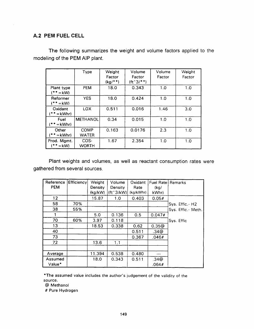
A.2 PEM FUEL CELL
The following summarizes the weight and volume factors applied to themodeling of the PEM AlP plant.
Plant weights and volumes, as well as reactant consumption rates weregathered from several sources.
'The assumed value includes the author's judgement of the validity of thesource.@ Methanol# Pure Hydrogen
149
Type Weight Volume Volume WeightFactor Factor Factor Factor(kg/**) (ft3/**)
Plant type PEM 18.0 0.343 1.0 1.0(* * = kW)Reformer YES 18.0 0.424 1.0 1.0(* * = kW)Oxidant LOX 0.511 0.016 1.46 3.0
( = kWhr)Fuel METHANOL 0.34 0.015 1.0 1.0
(* = kWhr)Other COMP 0.163 0.0176 2.3 1.0
(* = kWhr) WATERProd. Mgmt. COS- 1.67 2.354 1.0 1.0
(* = kW) WORTH
Reference Efficiency Weight Volume Oxidant Fuel Rate RemarksPEM Density Density Rate (kg/
(kg/kW) (ft 3/kW) (kg/kWhr) kWhr)12 15.87 1.0 0.403 0.05#58 70% Sys. Effic.- H238 55% _ _Sys. Effic.- Meth.1 5.0 0.136 0.5 0.047#
70 60% 3.97 0.118 Sys. Effic13 18.53 0.338 0.62 0.35@40 _ _ 0.511 .34@73 0.367 .046#72 13.6 1.1
Average 11.394 0.538 0.480 ---Assumed 18.0 0.343 0.511 .34@
Value* .064#

Each reference was reviewed for its consistency with other sources and toevaluate the basis of how the data was presented. From the estimates ofreactant consumption in kg/kWhr, the volumetric consumption rate was
computed assuming a density for the form of the reactant. For the PEM plant
with methanol and LOX:
Oxidant volume factor:
(0.511 kgWhr )(2.205 lb )(0.014 1)= 0.016 kWhr
Fuel volume factor:kg _ _ 3 - 1
(0. 34 hr )(2.205 kb ) (0.020 ) = 0.015 kWhr
To allocate volumes for the compensating water tanks and the weight of theempty tank structure, the following factors were calculated using standard tank
data from Reference [12]:
Compensating water volume:
(0. 511 hr )(2.205 )(0.0156 b)= 0.0176 fkPr
Compensating water weight:(0.511 k )(0n0156ft3 20.4 Ib of tank= 1 kg
0.511 l)( 0156b ft3 of reactant kWhr
Other fuel and oxidant options for the PEM plant are detailed in Appendix
B. Reformer and product management estimates are contained in Appendix B.
A.3 MOLTEN CARBONATE FUEL CELL
The following summarizes the weight and volume factors applied to the
modeling of the MCFC AIP plant.
150
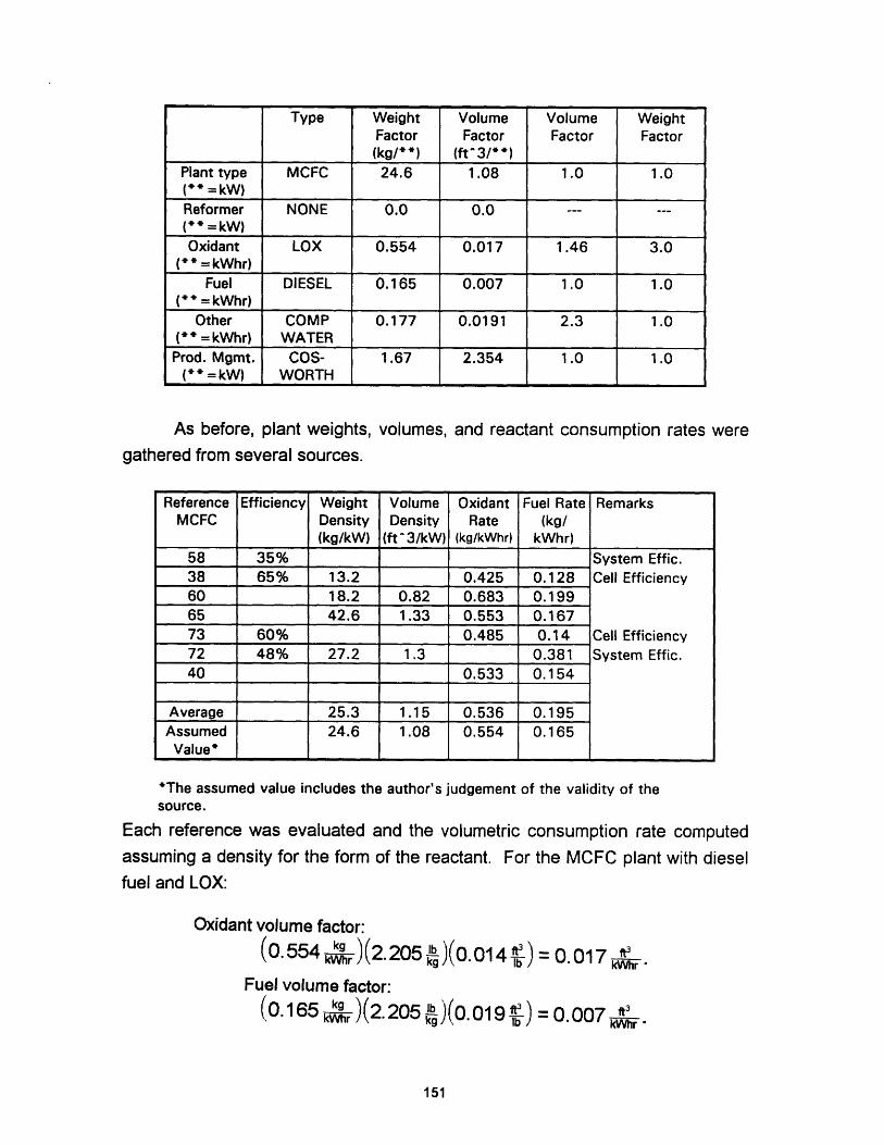
As before, plant weights, volumes, and reactant consumption rates weregathered from several sources.
'The assumed valuesource.
includes the author's judgement of the validity of the
Each reference was evaluated and the volumetric consumption rate computedassuming a density for the form of the reactant. For the MCFC plant with dieselfuel and LOX:
Oxidant volume factor:
(0.554 k)(2.205b )(0.014 b) = 0.017 kWhr
Fuel volume factor:
(0.165 kW )(2.205 b ) ( 0 1 9 ft3 )=0.007 9-kh kg lb = t 0
151
Type Weight Volume Volume WeightFactor Factor Factor Factor(kg/* *) (ft^3/*+)
Plant type MCFC 24.6 1.08 1.0 1.0(** =kW)Reformer NONE 0.0 0.0 --- ---(* * = kW)Oxidant LOX 0.554 0.017 1.46 3.0
( * = kWhr)Fuel DIESEL 0.165 0.007 1.0 1.0
(* = kWhr)Other COMP 0.177 0.0191 2.3 1.0
( * = kWhr) WATERProd. Mgmt. COS- 1.67 2.354 1.0 1.0
(* = kW) WORTH
Reference Efficiency Weight Volume Oxidant Fuel Rate RemarksMCFC Density Density Rate (kg/
(kg/kW) (ft^3/kW) (kg/kWhr) kWhr)58 35% System Effic.38 65% 13.2 0.425 0.128 Cell Efficiency60 18.2 0.82 0.683 0.19965 42.6 1.33 0.553 0.16773 60% 0.485 0.14 Cell Efficiency72 48% 27.2 1.3 0.381 System Effic.40 0.533 0.154
Average 25.3 1.15 0.536 0.195Assumed 24.6 1.08 0.554 0.165Value*

Compensating water volume:
(0.554 Whr)(2.205 b )(0.0156b ) = 0.0191 kW Compensating water weight:
Compensating water weight:
(0.554 k )(0.0156 t3 )20 4 lb of tank
A.4 ALUMINUM OXYGEN SEMI-Cb ft3 tanELL
A.4 ALUMINUM OXYGEN SEMI-CELL
=0.177 kgkWhr
The table above summarizes the weight and volume information gathered
from several sources.Reference Efficiency Weight Volume Oxidant Fuel Rate Remarks
ALOX Density Density Rate (kg/(kg/kW) (ft^3/kW) (kg/kWhr) kWhr)
12 55.33# 3.5 0.26 0.28 KOH + H20=0.898kg/kWhr
72 86.2@ 4.613 117.3@ 0.276 KOH+H20
=0.896kg/kWhr
40 0.263 KOH + H20= 0.898kg/kWhr
Average --- 4.05 0.266 0.280Assumed 55.33# 3.50 0.263 0.280 0.898 (KOH + H20)
Value* I
*The assumed value includes thesource.# without aluminum@ includes aluminum in cell
author's judgement of the validity of the
152
Type Weight Volume Volume WeightFactor Factor Factor Factor(kg/**) (ft^3/**)
Plant type ALOX 55.3 3.5 1.0 1.0(** =kW)
Reformer NONE 0.0 0.0(+* =kW)Oxidant LOX 0.263 0.008 1.46 3.0
(* = kWhr)Fuel ALUMINUM 0.28 0.0 1.0 1.0
(* = kWhr)Other KOH/ 0.898 0.0318 1.33 2.3
( * = kWhr) WATERProd. Mgmt. NONE 0.0 0.0 --- ---
(* = kW)
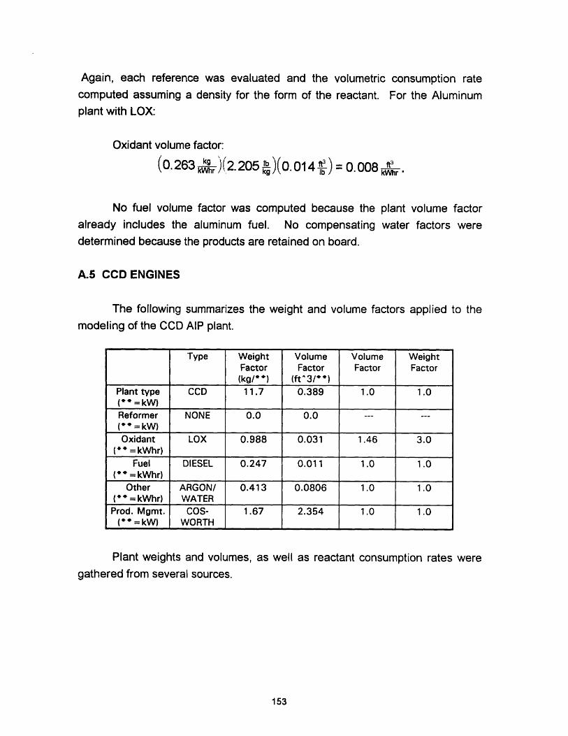
Again, each reference was evaluated and the volumetric consumption ratecomputed assuming a density for the form of the reactant. For the Aluminumplant with LOX:
Oxidant volume factor:
(0.263 2.205 lb )(0.014 ) = 0.008 kWhr
No fuel volume factor was computed because the plant volume factoralready includes the aluminum fuel. No compensating water factors weredetermined because the products are retained on board.
A.5 CCD ENGINES
The following summarizes the weight and volume factors applied to the
modeling of the CCD AIP plant.
Plant weights and volumes, as well as reactant consumption rates were
gathered from several sources.
153
Type Weight Volume Volume WeightFactor Factor Factor Factor(kg/**) (ft^3/ )
Plant type CCD 11.7 0.389 1.0 1.0(** =kW)Reformer NONE 0.0 0.0 --- ---(** =kW)
Oxidant LOX 0.988 0.031 1.46 3.0(* = kWhr)
Fuel DIESEL 0.247 0.011 1.0 1.0(° = kWhr)
Other ARGON/ 0.413 0.0806 1.0 1.0(+ + = kWhr) WATERProd. Mgmt. COS- 1.67 2.354 1.0 1.0
(+* = kW) WORTH

'The assumed valuesource.
includes the author's judgement of the validity of the
The volumetric consumption rate was computed assuming a density for the form
of the reactant. For the CCD plant with diesel fuel and LOX:
Oxidant volume factor:(0. 988 kWhr )(2.205 b (0.014 fe= 0. 031 kWhr .
Fuel volume factor:(O.247 hkg )(2.205)o. 019 l) = 0.011 r
kg /:. 09i Mr
Argon volume factor:
(0.038 kr )(0.6165kg q)(3.281 t ) = 0.827 hr
The Argon weight and volume factors are combined with the compensating water
factors for entry into the "other' reactant category of the model:
Argon volume:
Argon weight:
(0.827 kWhr )(0.00274) 0. 00227 kWhr (O kW).6i=0098kWhr
(0.038 gr )(2.6) = 0.0988 kgkWhr'
Comp. water volume: (0. 988 hr )(2.205 b )(0. 01 56 )(2.3) =0. 078 kWhr
Comp. water weight: (0.988 khr )(0.0156 20.4 lb of tankkWhr2. lbJ ft of reactant = 0.314 kgkVhr '
154
Reference Efficiency Weight Volume Oxidant Fuel Rate RemarksCCD Density Density Rate (kg/
(kg/kW) (ft^3/kW) (kg/kWhr) kWhr)
38 30% System Effic.1 5.88 0.25 1.0 0.3
47 18.4 3.57 0.985 0.2870 10.6 0.63 0.28465 6.1 0.388 1.14 0.18729 0.84 0.24 Ar-0.038 kg/kWhr73 33% 0.873 0.252 System Effic.72 33% 18.14 1.0 System Effic.40 0.642 0.185
Average 11.8 1.118 0.913 0.247Assumed 11.7 0.389 0.988 0.247
Value' I I

Combined volume:
Combined weight:
0. 00227 + 0.078 = 0. 0806 kWhr.
0.0988 + 0.314 = 0.413kWhr .
Because argon and compensating water are combined, volume and weight
factors are applied before the two are added. See Appendix B for argon weightand volume factors.
A.6 STIRLING ENGINES
The following summarizes the weight and volume factors applied to the
modeling of the Stirling AIP plant.
The following plant weights and volumes and reactant consumption rates
were gathered from several sources.
155
Type Weight Volume Volume WeightFactor Factor Factor Factor(kg/ * ) (ft 3/* + )
Plant type STIRLING 11.54 0.487 1.0 1.5(* * = kW)Reformer NONE 0.0 0.0 --- ---(* * = kW)Oxidant LOX 1.0 0.031 1.46 3.0
(* " = kWhr)Fuel DIESEL 0.26 0.011 1.0 1.0
(* * = kWhr)Other COMP 0.319 0.0345 2.3 1.0
(" * = kWhr) WATERProd. Mgmt. COS- 1.67 2.354 1.0 1.0
(= * = kW) WORTH
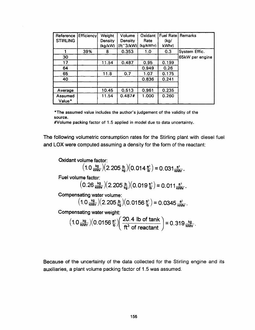
'The assumed value includes the author's judgement of the validity of thesource.#Volume packing factor of 1.5 applied in model due to data uncertainty.
The following volumetric consumption rates for the Stirling plant with diesel fuel
and LOX were computed assuming a density for the form of the reactant:
Oxidant volume factor:
(1.0 kr )(2.205 b )(0.014 )=0 .031 kWhr
Fuel volume factor:
(0.26 kr )(2.205 kb )(0.019 lb=0.011 kWhr
Compensating water volume:
(1-0 r )(2.205 kb )(0.0156 ) 0.0345 kWhrMr kg lb kV.345 hr
Compensating water weight:
(1.0 kWhr )(0.0156 ) 20.4 lb of tank = 0.319 kg
ft3 of reactantr '
Because of the uncertainty of the data collected for the Stirling engine and its
auxiliaries, a plant volume packing factor of 1.5 was assumed.
156
Reference Efficiency Weight Volume Oxidant Fuel Rate RemarksSTIRLING Density Density Rate (kg/
(kg/kW) (ft 3/kW) (kg/kWhr) kWhr)
1 39% 8 0.353 1.0 0.3 System Effic.30 65kW per engine17 11.54 0.487 0.95 0.19964 0.949 0.2665 11.8 0.7 1.07 0.17540 0.836 0.241
Average 10.45 0.513 0.961 0.235Assumed 11.54 0.487# 1.000 0.260
Value*
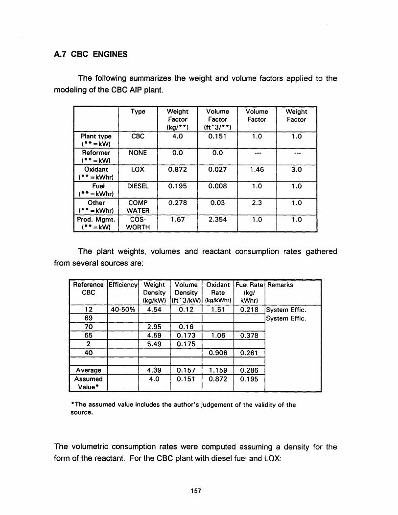
A.7 CBC ENGINES
The following summarizes the weight and volume factors applied to the
modeling of the CBC AIP plant.
The plant weights, volumes and reactant consumption rates gatheredfrom several sources are:
'The assumed value includes the author's judgement of the validity of thesource.
The volumetric consumption rates were computed assuming a density for theform of the reactant. For the CBC plant with diesel fuel and LOX:
157
Type Weight Volume Volume WeightFactor Factor Factor Factor(kg/*+) (ft'3/ *)
Plant type CBC 4.0 0.151 1.0 1.0(** = kW)Reformer NONE 0.0 0.0 --- ---
(* * = kW)Oxidant LOX 0.872 0.027 1.46 3.0
(* = kWhr)Fuel DIESEL 0.195 0.008 1.0 1.0
( = kWhr)Other COMP 0.278 0.03 2.3 1.0
(* * = kWhr) WATERProd. Mgmt. COS- 1.67 2.354 1.0 1.0
( + = kW) WORTH
Reference Efficiency Weight Volume Oxidant Fuel Rate RemarksCBC Density Density Rate (kg/
(kg/kW) (ft 3/kW) (kg/kWhr) kWhr)12 40-50% 4.54 0.12 1.51 0.218 System Effic.69 System Effic.70 2.95 0.1665 4.59 0.173 1.06 0.3782 5.49 0.17540 0.906 0.261
Average 4.39 0.157 1.159 0.286Assumed 4.0 0.151 0.872 0.195
Value*

Oxidant volume factor:
(0.872 kr )(2.205lb)(0.014 ) = 0.027 kGhr .
Fuel volume factor:rkg lb t3
(0. 195 kVVhr )(2.205 k )(0. 019 if) = O. 008 kWhr
Compensating water volume:
(0.872 kg )(2.205 b )(0.0156 ) 0.03 kW
Compensating water weight:
(0872 k)(00156 20.4 of tankMlr ft3 of reactant
kgIkWr '
A.8 LEAD ACID BATTERY
The data taken is the same used in the baseline submarine battery
determination in Appendix C, with the final results repeated here for ease in
comparison to other battery types:
LEAD ACID BATTERY DATA
2 hour capacity (kW-hr) 1600
5 hour capacity (kW-hr) 2035
80+ hour capacity (kW-hr) 2645.5
Weight (Itons) 76.4
Volume (ft3) 800
No. Batteries Burst 5.51
No. Batteries Creep 5.08
Coulombic Efficiency 0.9
158

A.9 Ni/Cd BATTERY
For comparison purposes, the lead acid battery was developed based on
a standard battery unit having a nominal total voltage of 240 VDC. A standard
Ni/Cd battery will be determined based on the same total battery voltage.
The following summarizes data sources and their estimates for weights,
volumes and battery capacity:
'The assumed value includes the author's judgment of the validity of the source.
As a result a standard
characteristics:
Ni/Cd battery is determined to have the following
1 hr capacity: (5000 Amphr)(231V) = 1155 kWhr
Weight: (155 k Whr )(1000Wh o )2b2 = 34.38 Itons
Volume: (115~ r)= 642 ft3
Reference [23] gives the following figure for Ni/Cd battery capacities other than
a standard 1-hour (1 C) rate:
159
Reference Efficiency Energy Energy RemarksNi/Cd Density Density
(kWh/ft 3) (Wh/lb)
71 1.72 13.57 5000 A, 231 VDC @ 1 hour rate4 1.8 15.0 @ 1 hour rate
Average 1.76 14.29Assumed 90% 1.8 15Value'

120
0-
)- 100I-U
IloC 80
a:
0.1C IC IOC
DISCHARGE RATE
Ni/Cd Capacity vs. Discharge Rate
Figure A.1
From this figure, the following scaling factors for battery capacity are assumed:
1 hour rate
2 hour rate (% of 1 hour rate)
80+ hour rate (% of 1 hour rate)
factor
1.0
1.04
1.1
Capacitv1155 kW-hr
1201 kW-hr
1270 kW-hr
Using the required energy required for a 4 knot, 90 hour transit and 20 knot, 2
hour burst from Appendix C, the following number of standard batteries are
required:
8814 kVWhr = 7.34 Batteries (burst)1201 Wbhs )13692 kWhr 10.78 Batteries1270 kWhr 10.78 Batteries creep)Batt"e'~
160
l -
__
C. n

SUMMARY OF Ni/Cd BATTERY DATA
1 hour capacity (kW-hr) 1155
2 hour capacity (kW-hr) 1201
80+ hour capacity (kW-hr) 1270
Weight (Itons) 38
Volume (ft3) 670
No. Batteries Burst 7.34
No. Batteries Creep 10.78
Coulombic Efficiency 0.9
A.10 LAIS BATTERY
The standard LAIS battery will be determined based on a total battery
voltage of 240VDC.
From the data presented on the next sheet, a standard LAIS battery is
determined to have the following characteristics:
240 Vos - 1 0 Cells)(45kWhr) = 450kWhr2 40 Mr 1000 Wh Cell) l )36 Itn
45 1s k_ r _l Wh 2.205 lb)( ons = 3.69 ItonsWeight: (cWr120 -) kWhr kg J\ 2240 lb )
Volume: (45h0 kWr )(1000 wh)( m3 )( t ) = 72.24 ft 3
\220 r kWr 1000 1 0.3048 m
The following summarizes data sources and their estimates for weights,
volumes and battery capacity:
161

*The assumed value includes the author's judgment of the validity of the source.
Because the LAIS battery is projected to have similar discharge characteristics
to the lead acid battery the following scaling factors are assumed:
5 hour rate
2 hour rate (% of 5 hour rate)
80+ hour rate (% of 5 hour rate)
factor
1.0
0.83
1.3
Capacity450kW-hr
369 kW-hr
858 kW-hr
Using the required energy required for a 4 knot, 90 hour transit and 20 knot, 2
hour burst from Appendix C, the following number of standard batteries are
required:
8814 kWhr - 23.89 Batteries (burst)af'tery
13692 kWhr -23.41 Batteries (creep)585BatRtey
SUMMARY OF LAIS BATTERY DATA
2 hour capacity (kW-hr) 369
5 hour capacity (kW-hr) 450
80+ hour capacity (kW-hr) 858
Weight (Itons) 3.69
Volume (ft3) 72.24
No. Batteries Burst 23.89
No. Batteries Creep 23.41
Coulombic Efficiency 1.0
162
Reference Efficiency Energy Energy RemarksLAIS Density Density
(Wh/l) (Wh/kg)
58 20043 100% 350 130 45 kWhr at 24 VDC10 122 70.5615 160 1904
Average 208 130.19Assumed 220 120
Value*
APPENDIX B
REACTANT DOCUMENTATION
B.0 OVERVIEW
This appendix contains supporting data and calculations for the reactants
and discussed in Chapter 5, and modeled in Chapter 6. Material properties
taken from References [32,48].
Section
Summary of reactant packing factors
Reformer
Exhaust Product Management
Oxidants
Liquid Oxygen (LOX)
Gaseous Oxygen
High Test Hydrogen Peroxide (HTP)
Sodium Perchlorate
Hydrogen
Liquid Hydrogen
Gaseous Hydrogen
Metal Hydride
Other Fuels
Other Reactants
Paqe No.
164
164
165
167
167
169
170
170
171
171
172
172
173
173
163
B.1
B.2
B.3
B.4
B.4.1
B.4.2
B.4.3
B.4.4
B.5
B.5.1
B.5.2
B.5.3
B.6
B.7
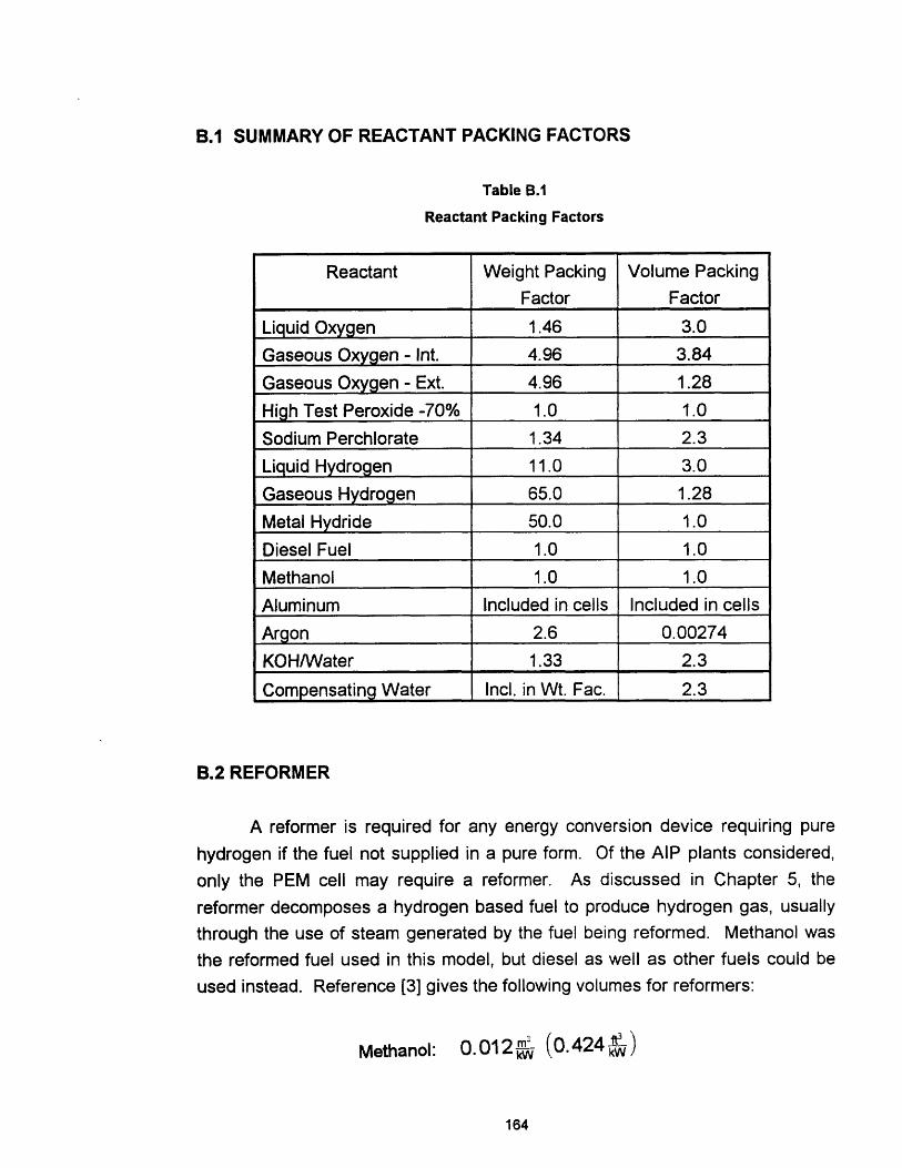
B.1 SUMMARY OF REACTANT PACKING FACTORS
Table B.1
Reactant Packing Factors
Reactant Weight Packing Volume Packing
Factor Factor
Liquid Oxygen 1.46 3.0
Gaseous Oxygen - Int. 4.96 3.84
Gaseous Oxygen - Ext. 4.96 1.28
High Test Peroxide -70% 1.0 1.0
Sodium Perchlorate 1.34 2.3
Liquid Hydrogen 11.0 3.0
Gaseous Hydrogen 65.0 1.28
Metal Hydride 50.0 1.0
Diesel Fuel 1.0 1.0
Methanol 1.0 1.0
Aluminum Included in cells Included in cells
Argon 2.6 0.00274
KOH/Water 1.33 2.3
Compensating Water Incl. in Wt. Fac. 2.3
B.2 REFORMER
A reformer is required for any energy conversion device requiring pure
hydrogen if the fuel not supplied in a pure form. Of the AIP plants considered,
only the PEM cell may require a reformer. As discussed in Chapter 5, the
reformer decomposes a hydrogen based fuel to produce hydrogen gas, usually
through the use of steam generated by the fuel being reformed. Methanol was
the reformed fuel used in this model, but diesel as well as other fuels could be
used instead. Reference [3] gives the following volumes for reformers:
Methanol: 0.012 - (0.424 )
164
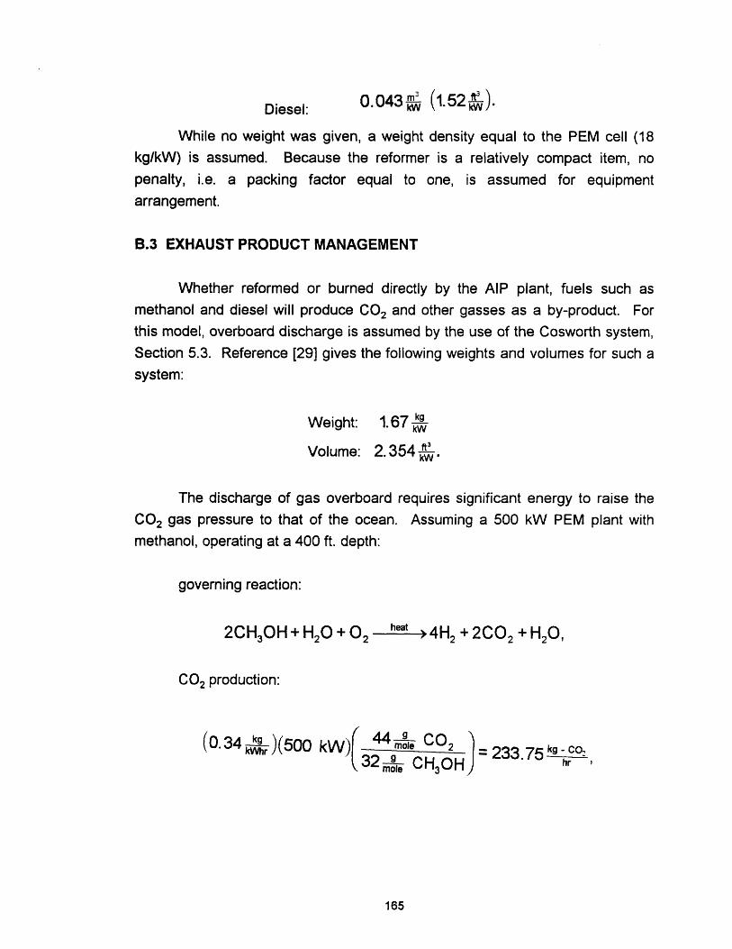
Diesel: 0.043kW (1W52-)
While no weight was given, a weight density equal to the PEM cell (18
kg/kW) is assumed. Because the reformer is a relatively compact item, no
penalty, i.e. a packing factor equal to one, is assumed for equipment
arrangement.
B.3 EXHAUST PRODUCT MANAGEMENT
Whether reformed or burned directly by the AIP plant, fuels such as
methanol and diesel will produce CO2 and other gasses as a by-product. For
this model, overboard discharge is assumed by the use of the Cosworth system,
Section 5.3. Reference [29] gives the following weights and volumes for such a
system:
Weight: 1.67 kg
Volume: 2.354 w
The discharge of gas overboard requires significant energy to raise the
CO2 gas pressure to that of the ocean. Assuming a 500 kW PEM plant with
methanol, operating at a 400 ft. depth:
governing reaction:
2CH3OH + H20 + 02 hea 4H2 + 2C0 2 + H20,
CO2 production:
(0.34~7)(50 kWj kW CO = 233.75 kg CO32 CH3OH hr
165

ocean back pressure at a depth of 400 ft:
(400 feet)(100 feet ofdepth ) 14.7 psia = 190.7 psia.
Assuming an ideal gas withy = 1.33, initial temperature of 3000K and 14.7 psia:
=> T2 = (300°K {)190. 7psia
14. 7psia
1.33-11.33
= 566.6 ° K,
the change in enthalpy for CO2 is [32]:
At 5660K: hco = 2.720 kcalmole
At 3000 K: -hco = 0.016 kcalmole
A hco = 2.704 kcal11C 2 7O4 mole*
Assuming a compressor efficiency of 0.80, the work required to compress the
gas is
2.704 kcal
0.8)(moleC 02 )1000
44g . kg4. 184 }
9
=3.21e 5 kg,
(3. 21e k)(233.75 '(36-0) = 20.9J {kW},
which amounts to 4.2 percent of the AIP plant output. Fuel consumption rates
for AlP plants include this penalty.
The other major by-product of fuel cells is pure water, which is assumedto be stored on board for consumption or transferred to the variable ballast
system.
166
(T2T)
-1
P2 r
1

B.4 OXIDANTS
B.4.1 LIQUID OXYGEN
In the model, LOX was assumed to be stored inside the pressure hull in
an arrangement similar to Figure B.1. If the "oxygen compartment" takes up one
half the cross-section of a 31 ft. diameter hull, and the external diameter of each
LOX tank is 12 ft., then the ratio of area "A" to the total cross-section of the LOX
tanks is:
Liquid Oxygen Tank Arrangement
Figure B.1
Area "A": (312 ) = 754.8 ft2
167
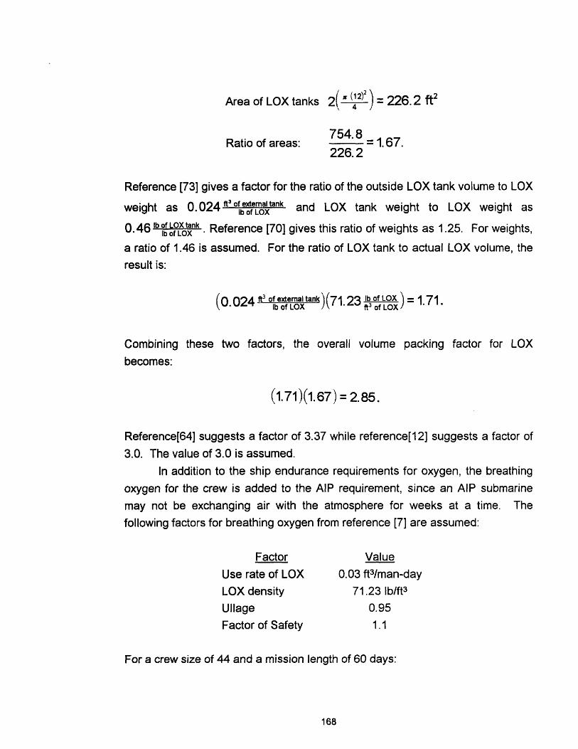
Area of LOX tanks 2( (2)) = 226.2 ft2
Ratio of areas:754.87548 = 1.67.226.2
Reference [73] gives a factor for the ratio of the outside LOX tank volume to LOX
weight as 0.024 ft 3 o ex te a l tank and LOX tank weight to LOX weight as
0.46 b f LOXtank . Reference [70] gives this ratio of weights as 1.25. For weights,
a ratio of 1.46 is assumed. For the ratio of LOX tank to actual LOX volume, the
result is:
(0.024 of etank )(7123 lb of LOX) = 1.71.
Combining these two factors, the overall volume packing factor for LOX
becomes:
(1.71)(1.67) = 2.85.
Reference[64] suggests a factor of 3.37 while reference[12] suggests a factor of
3.0. The value of 3.0 is assumed.
In addition to the ship endurance requirements for oxygen, the breathing
oxygen for the crew is added to the AIP requirement, since an AIP submarine
may not be exchanging air with the atmosphere for weeks at a time. The
following factors for breathing oxygen from reference [7] are assumed:
Factor
Use rate of LOX
LOX density
Ullage
Factor of Safety
Value
0.03 ft3 /man-day
71.23 Ib/ft3
0.95
1.1
For a crew size of 44 and a mission length of 60 days:
168

cubic feet of LOX:
(0.03 mf3day )(44 men)(60 days)(1.05)(1.1) = 91.71 ft3 ,
tons of LOX:
(71.23 )(91.71 ft3)( 2240 ) 2.92 Itons.
This total is added to the total LOX for AIP endurance before the volume and
weight packing factors are applied. For applications where LOX was not
specified as the AIP oxidant, LOX was still assumed for breathing with packing
factors applied.
B.4.2 GASEOUS OXYGEN
The storage of oxygen as a gas was assumed to be in high pressure
cylinders at 3000 psi. The volumetric consumption of oxygen, based on the
specific oxygen consumption of the PEM cell in Appendix A is
(0.511 kgr )(2. 2 05 )( .059 ) = 0. 066 kWhr.kW khr kg lb, and is used in the oxidant storage method comparison.
Reference [65] gives the following factors for tank weight and volume:
Ratio Factor
Wt. Tank + Oxygen / Wt. Oxygen 4.96
Vol. Tank + Oxygen / Vol. Oxygen 1.28.
This storage of oxygen could be either internal or external to the pressure hull.
An internal area analysis similar to the LOX case in Section B.4.1 gives a ratio ofgas cylinder cross-section to area "A" of 3.0, and when multiplied by the volume
factor above, a final packing factor of 3.84 is obtained. If the cylinders are
stored outside the pressure hull, i.e. in a main ballast tank, then 100 percent
169

utilization of the area around the cylinders is assumed and the factor of 1.28
alone is applied. The weight factor of 4.96 is assumed to include the weight of
the tank supports.
B.4.3 HIGH TEST PEROXIDE
HTP (70 percent) contains 33 w/o oxygen and is the concentration
assumed in the model. At this concentration HTP is considered to be "safe" to
handle with care. HTP decomposes by:
H22 H20 > H 20 + 0 2
For 70 percent HTP, there are 2.06 moles of H20 2, and also 0, per 100 grams of
solution. Therefore, based on the specific oxygen consumption of the PEM cell,
the volumetric consumption of HTP is:
( kg 100 grams H20 2 ](0 012 F )(2.205 lb) = 0. 0399 r0.kwhr I 2.06 moles l15.994 grams .,b of K kg kWhr
L-~gr)/~~~~mole of
Storage of HTP is assumed to be in plastic bladders in self compensating
tanks external to the pressure hull with 100 percent utilization of the space,
resulting in a packing factor of 1.0 for weight and volume.
B.4.4 SODIUM PERCHLORATE
The storage of sodium perchlorate is modeled as contained in pressure
vessels, similar in construction to other steel tanks found onboard a submarine,
and containing approximately 39 w/o Oxygen. Assuming the specific oxygen
consumption rate for the PEM cell, the volumetric rate is:
(0.511 kg Ox (2.56 kg Na, )(0.4 m)(1000 9 )(0.061 in ) (0. 083 = 0.0186 rhrReference [12] givesOx standard tank factors for volume and weight:
Reference [12] gives the following standard tank factors for volume and weight:
170
Ratio Factor
lb of tank / ft3 of reactant 20.4
ft3 of arrangeable tank volume 2.3./ ft3 of reactant
For weight, the tank factor now becomes:
(1kg Ox)(2.56 kg NaCO, )(400ml)(3.53e- )(24ft3 elbtank 0 336 kg tank kg Ox kgI= 4k tank0.45 0.336 tank,
factor = 1.34.
B.5 HYDROGEN
B.5.1 LIQUID HYDROGEN
Similar ideas apply to Liquid Hydrogen (LH) as they did to LOX, except
that LH must be stored at a much colder temperature so the insulation will
probably be thicker, and that LH requires more volume to store a given weight of
reactant.
First the specific consumption of pure hydrogen must be calculated.
Assuming the methanol flow rate for the PEM cell and the following reaction:
CH3OH+ H2 0 - CO 2 + 3H2,
specific H2 consumption:
(34 kg CHH ) 6.048 grams H2 .064kg H2kWhr 32.0414 grams CH 3OH) kWhr
To calculate the volumetric consumption:
(0.064 kr )(14. 1 )(1000 g )(0. 061 )(0.083 ) = 0.032 khr ·kWhr 9k g nkl
171
Reference [73] gives the value of 0.043 kWhr, SO an average value of
0.038 1T is assumed. Reference [73] also gives a tank to hydrogen weight
ratio of 10, thus a factor of 11 is assumed for the ratio of total tank plus LH
weight to LH weight. The same volume packing factor that was used for LOX is
assumed for LH.
B.5.2 GASEOUS HYDROGEN
The storage of hydrogen as a gas was assumed to be in high pressure
cylinders at 3000 psi similar to the gaseous oxygen storage in Section B.4.2. A
significant difference however involves the density of hydrogen which is much
lower than for oxygen.
Assuming the specific hydrogen consumption rate of Section B.5.1, the
volumetric consumption is:
(0.064 Whr )(2.205 g)(1 b ) = 0.141 khr
Reference [57] gives a ratio of 90 lb of HTank while reference [73] gives
55.1 lbofHTank A value of 65 was assumed in the model. The storage
cylinders are assumed to be similar in construction and arrangement to those for
oxygen, except that due to safety considerations, only external storage was
considered with a volume packing factor of 1.28.
B.5.3 METAL HYDRIDE
A regenerable metal hydride similar to the form FeTiMg was assumed.
For an estimate of the volumetric consumption rate, the hydrogen consumption
rate of Section B.5.1 was assumed and the following storage densities were
considered:
Reference Storage density (ft3/lb)
36 0.188
56 0.812
73 0.333
assumed value 0.4
172

resulting in:
(0.064 kr )(0.4 )(2.205 kg )= 0.056 r kV~h lb kg kWhr
The weight percent of hydrogen in a hydride is estimated by many
sources to be between 1 and 3.5 w/o, depending on the storage medium [56].
For the model, a weight percent of 2.0 was assumed yielding a weight factor for
hydride storage of 50. Because the volume estimate includes the storage
medium, no additional volume penalty is required.
B.6 OTHER FUELS
The volume factors for other fuels were calculated in Appendix A with itsparticular AIP application. Methanol is immiscible in water, thus is stored in a
seawater compensated tank external to the pressure hull, bladders similar to
those used for HTP must be employed. In this case, the volume and weight
packing factors are assumed to be 1.0 because 100 percent of the volume in the
tank can be used and the tank weight is included as a part of the hull structure
which scales with the size of the submarine. The same argument applies for
diesel fuel except that bladders are not required because diesel fuel and water
do not mix.
The weight and volume factors for aluminum are a default value of 1.0.
While the specific aluminum consumption is computed, the volume is included in
the size of the cell stacks, thus there is no additional weight or volume penalty.
B.7 OTHER REACTANTS
The storage of potassium hydroxide (KOH) and water for the aluminum
cell is assumed to be in standard steel tanks, with typical internal arrangements.
Using the tankage weight and volume ratios for Section B.4.4:
for a specific consumption rate for KOH/H2 0 of 0.898 k, the
volumetric consumption rate is:
173

(0.898 kWhr )(0 001 g )(3.28 ) = 0.318 r
with a weight factor of:
(1kg KOH + H2O)(o0.001 m )(3.28 ) (20.4 lbrtan )(0. 454tn) = 0.33 k g tank,
factor = 1.33.
The volume packing factor is 2.3.
The only other fluid modeled is argon for the CCD engine. Reference [49]
gives data for standard 2500 psi gas storage cylinders. For storage of 2700 m3
of gas at STP:
Tank weight 7000 kg
Tank external volume 7.4 m3
Gas volume at STP: 2700 m3
For a specific consumption rate for argon of 0.038 kg , the volumetric
consumption rate is:
(0.038 kWhr )(0.617 (3. 28 )3 = 0.827 kWhr
the weight factor is:
3 7000 kg of tank = 1(kg Ar)0.617)(3.28k)3 2700 m3 of gas
factor = 2.6,
and the volume packing factor is:
7.4 m3 of tank =0002741700 m3 of gas )
174

APPENDIX C
BASELINE DIESEL ELECTRIC SUBMARINE
C.O INTRODUCTION
This appendix presents information on the baseline diesel electric
submarine used as a basis for the AIP model in this thesis [68].
C.1 Baseline Submarine Summary 175
C.2 Propeller Selection Summary 175
C.3 Lead Acid Battery Selection 179
C.4 MIT Math Model for the Baseline Submarine 180
C.1 BASELINE SUBMARINE SUMMARY
Table C.1 gives specific details on the performance and characteristics of
the baseline submarine with a profile view in Figure C. 1.
C.2 PROPELLER SELECTION SUMMARY
The standard propeller chosen for the model was the same as selected
for the Canadian Hybrid Submarine Design. This propeller was chosen by hand
calculation, Figure C.2 and Table C.3, and validated using MANEUVERING
TOOL software available from the US Navy Hydrodynamic Office through Draper
Laboratory in Cambridge, MA. The general propeller characteristics are
summarized In Table C.2
175
Profile View of the Baseline Submarine
Figure C.1
176
Table C.1
Baseline Diesel Electric Submarine
Characteristic ValueLength 210 feetDiameter 31 feetDisplacement Surfaced 2325 Itons
Submerged 2670 ItonsDiving Depth 900 feetRange: Snorting 10,000 nm
Submerged @ 4 knots 96.5 hoursSubmerged @ max speed 2 hours
Maximum Submerged Speed 20 knotsWeapons Number of Torpedo Tubes 6
Number of Reloads 19Crew 44Endurance 90 daysMobility: Installed SHP 5000
PC - 7 blade fixed pitch prop. 0.8633 - 12V 652 MB MTU Diesels 990 kWe eachLead Acid Battery: 2 hr Cap. 1600 kW-hr
80+ hr Cap. 2645 kW-hrVolume 4408 ft^3Weight 421 Itons
Table C.2
Summary of Propeller Characteristics
Propeller Diameter
Design Speed
Hull Efficiency
Rotational Efficiency
Open Water EfficiencyAdvance Coefficient
P/D Ratio
Propulsive Coefficient
15.5 feet
20 knots
1.27
1.03
0.66
0.77
1.1
0.862
177

I 1 l s - l l
- - 9 - m
--- I tt I - I Ill
t~--------- ·- -
; :
l
I
, A---
- - - , 1 1
I 7r ' ' i=__LII CS~
9 · * _ 1 _ _'..... -
;!
,
\ I- I ! 1 ,I
' _ _ i I I i
. ~~~ . 1
. \ I
1 . I 1 I
W' iI '\ . ;~~~~~~~~~~~~~~~~~~~~~~~~~~~~: I I 7""1 ;- X ' I i x i I
i \ I 1
I - J i7I I4 i
Z A
\l IiI.
i - - - _- -I- ' 4 i - --\ I \ I I Z. ,\'_H/ .,
i : --"-I._ ._..I I\ 1\ -\ lI
\l XC. , ,4(;ii 'd A - '/I \ ~' I - -~- ~11 --~q &~' jr!5~ ~ \" .1I : \
; I rZ i \ I
I I
,. 1 4, I:~~~~~~~~~~~~~~~~~~~~
2x .' \ts , UI I~b r a1<j9ds 11X mL 11<1<1m
~~I , :.~ -! IIC- I I i I.. l , ,, , , i j I - - _ ; I I
.12- , Z
! 2
- - , i Ij-. .- 7I- -1
I-,.I . I I
- .. ' . I.
Typt 8 7 blldtes r/ O.s
As . I . I _
- i l -
I
'/DI - ·I/D tD.'s t'- /D . - 1, o
IL.l _. iI I
I
.` _ '1�1 '� i
� -i
1 '� �'1 .--.. I
-- ,, I
: 9..--
I ...... i.
I I ! I
I- , - T - - - - - I
'x lI \
; -7p D' .~D
i ' i. .
Ks. .
II . I Il i d
(Db
0 A O
I
02 3 04 05 O0 09 1O 1t 12 13 14 1507 0
--
L__I i
· 1I i
I i II I I i--.
Ii ! i I 11
'xI I _ I
I | I ! .
I 1,I
Propeller Curve, 7 Blade, Type B
Figure C.2
178
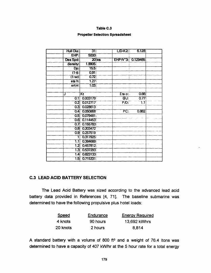
Table C.3
Propeller Selection Spreadsheet
C.3 LEAD ACID BATTERY SELECTION
The Lead Acid Battery was sized according to the advanced lead acid
battery data provided in References [4, 71]. The baseline submarine was
determined to have the following propulsive plus hotel loads:
Endurance
90 hours
2 hours
Enerav Required
13,692 kWhrs
8,814
A standard battery with a volume of 800 ft3 and a weight of 76.4 Itons was
determined to have a capacity of 407 kW/hr at the 5 hour rate for a total energy
179
Hull Dia: 311 L/D-K- 1 6.128EHP: 5000 i
_ Des Spd: 20 Ms EHP/N3:! 0.129485density: 1.9905
Dp: 15.5
(1-): 0.91 (1-w.) 0.721eta h: 1.271
_ ertrr: 1.031
J Kt Ea o: 0.660.1 0.003179 @J: 0.770.2 0.012717- P/D:' 1.10.3 0.028613 __
0.4 0.050868 PC:. 0.8620.5 0.079481 i0.6 0.11445310.7 0.15578310.8 0.203472_0.9 0.257519
1 0.317925'
1.1 0.384689i1.2 0.457812i1.3 0.537293 _
1.4 0.62313311.5 0.715331 .
Speed4 knots
20 knots

capacity of 2035 kWhrs. The following scaling factors were used to estimate the
battery capacity at burst (2 hours) and creep (80+ hours) endurance rates:
5 hour rate
2 hour rate
80+ hour rate
factor
1.00.8 % of 5 hr rate1.3 % of 5 hr rate
Capacity
2035 kWhr
1628 kWhr
2645.5 kWhr
Dividing the capacities into the required energy
battery size:
Endurance Requirement Numt
Burst
Creep
above results in the following
3er of Batteries
5.51
5.18
In order to meet both requirements, the larger battery was chosen, thus the total
battery weight and volume is:
Weight
420.96 Itons
Volume
4408 ft3
C.4 MIT MATH MODEL FOR THE BASELINE SUBMARINE
The MIT Math model, developed with MATHCAD 4.0 software by mathsoft
follows. The model is self explanatory and employs the same methodology used
in SUBSIZE.
180

MIT MATH MODEL - SS
Mode with increased battery 5/2/94 h - 33000ft lb
min
I. OWNER'S REQUIREMENTS (Enter the following owner's requirements)
Diving Depth (ft): D D :=900ft
SHP:
CREW Size:
Range: (@10 knots snorting)
Stores Period:
Number of Torpedo Tubes:
Number of Reloads:
Iton =2240 1b
knt :.515 . msec
SHP := 5000-hp
N T:44
E := 10000.knt hr
TS :90TT :=6
RL := 19
II. VOLUME REQUIREMENTS
Using owner's requirements and Figs 1-3, determine the densities for Mobility,Tubes and Reloads for your Boat:
Mobility Density:
Density/Tubes:
Density/Reloads:
ft 3
PMOB 6.7. -hp
PTT --.0042
RL . ft3.0036
V MOB = SHP. MOB
V WEAIS TT pTT + RLPRL
V C3I= 5300ft3
V MOB =3.35 104 · It3
V WEAPS =6.706' 10' 1t3
V C3I = 5.3' 103 fit3
SHIP SUPPORT: Area Analysis - assume a 7' deck height and consider
factors for passageway = 1.08 and hull curvature = 1.12
VPH 5.961 104
V aux : 03Rf3V pH + 9.3-fi3.N T V ux 2.198 103 'ftaUX
Berth & Mess:
Storerooms:
Other Spaces:(offices, etc)
Volume for ship support:
Pressure Hull:
VPH
Abm -1011 2 N T
A sr 8.5 fi2tTS
A bnm = 440' It2
A sr = 765'1t 2sr
Aos 120.ft2 + (.6.ft2N T) Aos = 146.4ft 2
V SS V aux+ 1. 127. ft 1.08. (A bm A sr Aos
V SS = 1.364 1 4 .ft 3
9.3ft3 .NTt (Abm AsrAos' 7.tl.() 8.1.12) VMOBt V\WEAPS+ VC'3 1
97
VPH = 5.913 104 '181
MOBILITY:
WEAPONS:
C^3 I:
Auxiliaries:
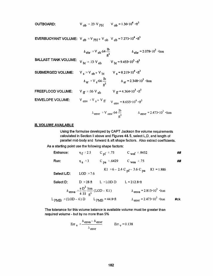
OUTBOARD: V ob :=. 2 3 .V PH V ob = 1.3 6 1 0 4 ft3
EVERBUOYANT VOLUME: Veb : V PH+ Vob Veb =7.273' 104 ft3
BALLAST TANK VOLUME:
SUBMERGED VOLUME:
FREEFLOOD VOLUME:
ENVELOPE VOLUME:
A ebr: =V eb64 lbft3
Vbt := .13V eb
Vs :=V eb+ V bt
lbAr = V 64.
ft3
V ff:=. 0 6 V eb
Venv -Vs+V ff
A ebr = 2.078 103 'Iton
V bt = 9.455.103 .fi3
Vs =8.219'104 ft3
as =2.348 103 Iton
V ff = 4.364 103 ft3
V = 8.655, 104 ft3env
A envr V e 64lbft3
A = 2.473 10- Itonenvr
Ill. VOLUME AVAILABLE
Using the formulae developed by CAPT Jackson the volume requirementscalculated in Section II above and Figures 4& 5, select L,D, and length ofparallel mid-body and forward & aft shape factors. Also extract coefficients.
As a starting point use the following shape factors:
1 f. = 2.5 C pf =.75
1 a 3 C pa .6429pa
C wsf .8452
C wsa =.75wsa'
KI =6 - 2.4.C pf- 3.6C pa KI = 1.886Select L/D: LOD: = 7.6
D :=28ft L :=LOD.D L =212.8fl
n.D 3 ItonA enva - (LOD - K1 )
4.35 ft3
LpM B =(LOD- 6) D LpMB = 44.8fl
A enva = 2.815 103 Iton
envl #ck
The tolerance for this volume balance is available volume must be greater thanrequired volume - but by no more than 5%
A enva -A envrErr v .
envr
Errv =0.138
182
Entrance:
Run:
Select D:
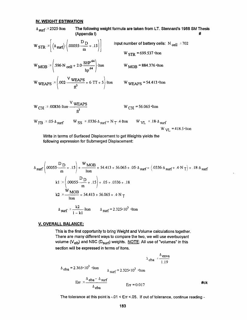
IV. WEIGHT ESTIMATION
A surf : = 2325. Iton The following weight formula are taken from LT. Stennard's 1988 SM Thesis(Appendix I) #
WSTR:= (sds) (.00°055 + .15
WMOB = .596.N cell + 2.0 64 ltonhp' 6 4
Input number of battery cells: N cell = 702
W STR = 699.537 lIton
W MOB = 884.376 Iton
V WEAPSW WEAPS : .002 +
ft36-TT + 5)lton W WEAPS = 54.413 lIton
V WEAPSWC3I = .00836 lton
ft3W C3I = 56.065 lIton
WFB := .05. Asurf W SS = .0336 A surf+ N T.4.lton W VL = 18Asurf
W VL =418.5 lton
Write in terms of Surfaced Displacement to get Weights yields thefollowing expression for Submerged Displacement:
U( DD00055 .15)m I
W MOB + oB + 54.413 + 56.065 + .05-A surf-- (.0336.Asurft+ .4N T) + ·1 8A surf
Iton
DDkl= .00055. +m
5) + .0+ .05 + .0336 + .18
W MOBk2 + 54 .4 13 + 56 .06 5 +. 4 N T
Iton
k2A surf - lton
1 - klA surf = 2.325 103 lIton
V. OVERALL BALANCE:
This is the first opportunity to bring Weight and Volume calculations together.There are many different ways to compare the two, we will use everbuoyant
volume (Veb) and NSC (Dsurf) weights. NOTE: All use of "volumes" in this
section will be expressed in terms of Itons.
A envaA eba -
1.19
A eba = 2.365X 10³ lton
A eba- A surErr :=
Aeba
A surf = 2.325' 10 'Iton
Err = 0.017
The tolerance at this point is -.01 < Err <.05. If out of tolerance, continue reading -
183
#ck

A. WEIGHT LIMITED CASE (Veb < Dsurf): Due to the uncertainty in your design at thispoint, you do not have the luxury of shaving weight. Therefore you must add buoyancy.Return to Section ill. and change shape factors, LOD (adding parallel mid-body) or D asappropriate for the magnitude of your imbalance.
B. VOLUME LIMITED CASE (Veb > Dsurf): Due to the uncertainty in your design you donot have the luxury of "tightening up the design." At this point add lead (fixed ballast) youwill have what is termed as a "lead mine."
C. Veb = Dsurf: After a couple iteration you should rewash this condition of designer'sbliss. The next step is to determine wetted surface and confirm final envelope.
Wetted Surface:
K2 := 6 - 2.4.C wsf - 3.6 C wsa
WS :=nD2(LOD - K2)
K2 = 1.272
WS = 1.559-104 .ft2
Check wetted surface:1. Entrance: Lf =2.4D Lf=67.2-ft xf =0,.1l1..67.2
L PMB = 44.8-ft
yf(x ) = I - [ft D
yf(x f).2.. ft dxf
2. Run:
WS f =4.995 103 .It2
La :=3 .6.D La = 100.8fta 0,. 11.. 100.8
ya(xa) (xaftl) ' D
La]2La
WSa :=
o
ya(xa).2.ftndx a WSa =6.65103 .f 2
WSfaWSfa WSa WSfa = 1.165104 1fl2
Final Envelope Displacement:
A e enva
WS : WS f + DL PMB
WS = 1.559-104 t2
A = 2.815.103 Iltone
This portion of the Math Model was deleted for brevity
and does not affect the result.
184
Lf
1t
WSf =
0
#ck
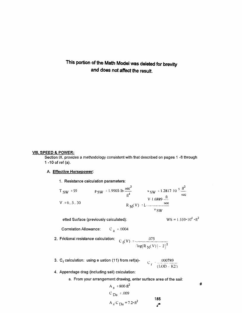
This portion of the Math Model was deleted for brevity
and does not affect the result.
VIII. SPEED & POWER:Section IX. provides a methodology consistent with that described on pages 1 -8 through
1 -10 of ref (a).
A. Effective Horsepower:
1. Resistance calculation parameters:
2 2TSW =59 Psw :- .99051bvSW - 1.2817 10
t SW t sec
V =0,.5..30 RN(V)
etted Surface (previously calculated):
Correlation Allowance: C a = .0004
2. Frictional resistance calculation: c t(V)lol
3. Cr calculation: using e uation (11) from ref(a)-
V. 1.6889. '-" .. see
vSW
WS = 1.559 1) t2
.075
g(R N(V)- 2)2
- ).00789
r (LOD - K2)
4. Appendage drag (including sail) calculation:
a. From your arrangement drawing, enter surface area of the sail:
As =800-1t2
C Ds -009
185A s' C Ds = 7.2-1 fi ,
#

b. For the remaining appendages, use the expression on pg 15-9 for AA*CdA:
App:= LD1000
App = 5.958'ft 2
5. Let's put it all together: we'll use equation (9) from ref(a)
EHP(V) =
1.5.104
1.104
EHP(V)
5000
0
.00872 v3 [ [WS (C r+ C V) + C a) t (A s CDs) + App]
2
0 10 20 30
V
B. Shaft Horsepower:1. Propeller Selection: Use series, rePropeller Open Water Efficiency-
2. Hull Efficiency: Use ref (a) Fig. 13-
3. Relative Rotative efficiency: Assume-rr:= 1.03
4. PC: PC:=tloIhqrr
5. SHP: SHP(V)
1.5.104
SHP(V)
5000
00
f (a) section 6, or other method to determine
o =.7 #
LOD - K2 = 6.328
'lh =1.24 #
EHP(V)
PC
5 10 15186 20
V
25 30
SHP(4) = 33.255
SHP(5) = 63.734
SHP(8) = 251.281
SHP( 10) = 482.35
SHP(12) = 822.073
SHP(15) = 1.579. 103
SHP(20) = 3.667' 103
c, Vn,',l\- _ A OA n. I n3
I I
…......... I
I I I I I
/
/
I " I I I
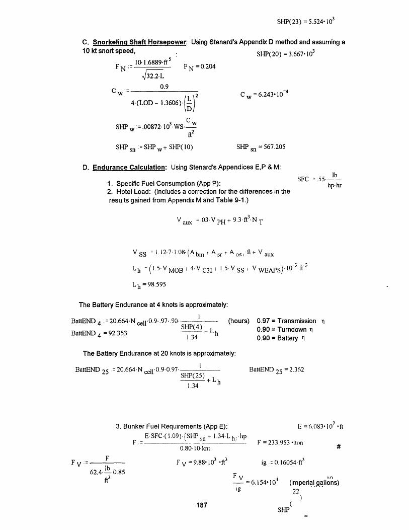
SHP(23) = 5.524, 103
C. Snorkelinq Shaft Horsepower: Using Stenard's Appendix D method and assuming a10 kt snort speed,
10. 1.6889fi '5
FN 32.2i32.2 L
SHP(20) = 3.667 103
F N = 0.204
0.9C =6.24310 - 4
4(LOD- .3606)- -
C wSHP w := 00872' 10 'W S
ft2
SHP sn := SHP W + SHP( 10) SHP sn = 567.205
D. Endurance Calculation: Using Stenard's Appendices E,P & M:
1. Specific Fuel Consumption (App P):2. Hotel Load: (Includes a correction for the differences in theresults gained from Appendix M and Table 9-1.)
SFC -.55 l--hp- hr
Vaux =.03V PH+993fl 3NT
V SS : 1.127 1.08(Abm Asrt + Aos/ fl+ V aux
Lh - (I5V MOB 4 V C3i 1.5 V SS V WEAPS)lO f
L h = 98.595
The Battery Endurance at 4 knots is approximately:
BattEND 4 = 20.664.N cell 0.9.97 . 90
BattEND 4 = 92.353 '---- + Lh1.34
(hours) 0.97 = Transmission 0.90 = Turndown
0.90 = Battery 11
The Battery Endurance at 20 knots is approximately:
BattEND 25 -= 20.664. N cell 0.9.0.97 SHP(25) L--- + L,
1.34
BattEND 25 = 2.362
FV = F
62.4 lb 0.85ft3
3. Bunker Fuel Requirements (App E):
E SFC ( 1.09). (SP sl t- 1.34- L h; ihpF ._ 0 1n
0.80.10 knt
F = 9.88.10 3 .ft3
F
E = 6.083 107 'ft
F = 233.953 ton
ig .= 0. 16054 lt3
(imperia!gallons)22
SHP
Cw =
11
%!
6.154-10'
187
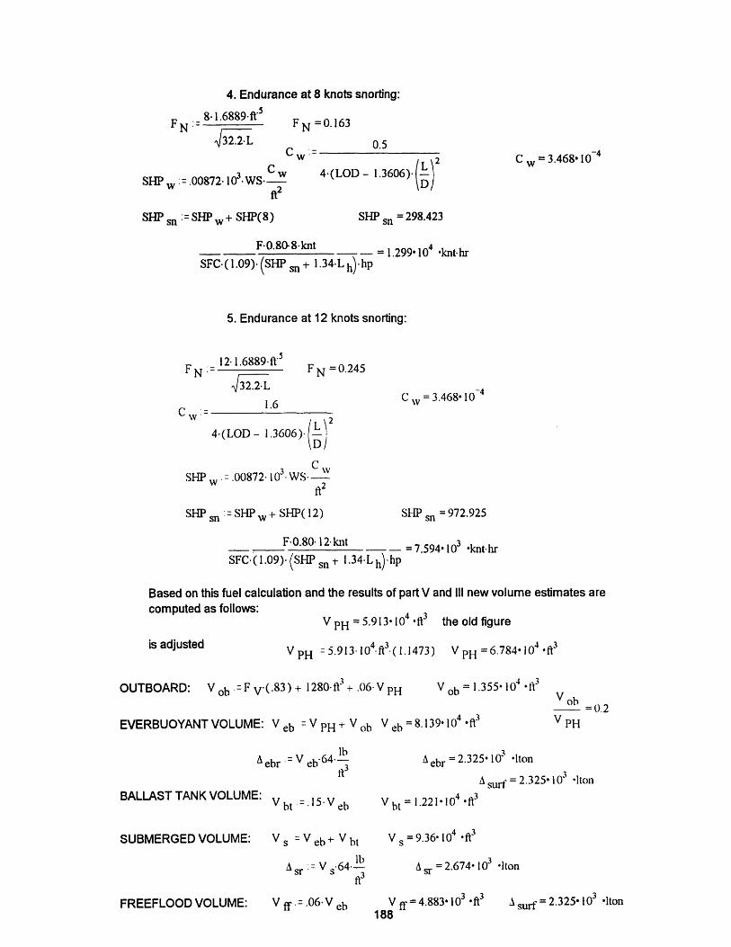
4. Endurance at 8 knots snorting:
8.1.6889fi 5
FN 32.2L
CwSHP .00872.103.WS-
2
FN =0.163
0.5
4 (LOD - 13 6 06 ) L )CW =3.468.10 - 4
SHP sn : = SHP w + SHP(8) SHP = 298.423sn
F-0.80-8knt - 1.299 104 knt. hr
SFC. 1.09). (SHP sn + 1.34-L h) hp
5. Endurance at 12 knots snorting:
12 1.6889 ft ' 5
FN ;=32.2 L
F N = 0.245
1.6
4(LOD- 1.3 6 0 6 ). (L) 2
D|J
CW =3.468 10 - 4
CSHP .00872. 103. WS.
ft2
SHP sn ':= SHP W + SHP(12) SHP sn = 972.925
F 0.80 12-knt - = 7.594 103 knt hr
SFC.(1.09). (SHP sn + 1.34 L h) hp
Based on this fuel calculation and the results of part V and Il new volume estimates arecomputed as follows:
is adjusted
V PH = 5.9 13 104 fl3 the old figure
VPH : 5.913.104.f3.(1.1473) V PH = 6 .7 8 4 104 of3
OUTBOARD: Vob .F V.(. 8 3 ) + 1280. ft3 + .06V PH V ob = 1. 3 5 5 104 Ift
EVERBUOYANT VOLUME: V eb V PHV H Vob V eb =8.139 104 ft3
A ebr = V eb 6 4 . lbft3
BALLAST TANK VOLUME:
SUBMERGED VOLUME:
FREEFLOOD VOLUME:
Vbt =15Veb
Vs =Veb+ Vbt
lb· 64-
r V s fi3
V ff =.06 V eb
A ebr = 2.325. 10' lton
A stu = 2.325' 103 Ilton
V bt = 1.221 10 .ft3
V =9.36 104 ft3
A sr =2.674 103 .It
V ff = 4.883 1l03 .ft3188
C W'
V ob0.2
V PH
A surf = 2.325- 103 Ilton
.L ~ .W -

ENVELOPE VOLUME: env V s - Vff V = 9.848 104 .113
A env : V env 64 . lbft3
A envr 2.814 103 .1ton
Err v = 4.058- 1 0-4 ie, the new pressure hullvolume agrees
Now adjust the components of pressure hull volume so thattheir total matches our new figure:
Auxiliaries:Vaux : =.03-VpH+ 9.3-ft3NT
V PH = 6 .7 84 104 .ft3
V aux 2.444. 103 ft3
Berth & Mess:
Storerooms:
Other Spaces:(offices, etc)
A bm: I=0ft2 N T(1.)
Asr 8.5f 2 T s(1.O)
Aos - 120.ft2 6. 2 NT)
Abm = 440 ft2
A r =765'ft 2
A = 146.41't 2os
Volume for ship support: V 8 V aux - 1. 127ftl. 1.08 (A bm r Asr r A os
V = 1.389 104 .fi3
V MOB =5000hp PMOB.(1.25) V MOB = 4 .1 8 8 104 *ft3
V WEAPS = 6.706()-' ·It
C^3 I: V C31 = 5300ft ( 1.0)
Now check to see if pressure hull volume OK:
V C31 = 53. 103 .ft3
V PH = 6.7841 04 .lit3
9.3 ft3 NTt AbmA sr + Aos 7 fl. (1.08.1.12) VMOB+ VWEAPS VC31
.97
SHP(4) = 33.255 SHP(20) = 3.667' 103
SHP( 10) =482.35 SHP(21 ) =4.231 103
SHP(22) = 4.849' 103
SHP(23) = 5.524. 103
V PH = 6.777 104 .It3
V ob = 1.355 104 fi3
V eb = 8.139 104 '1i3
V bt = 1.2 2 1 104 ft3
V = 9.36 104 .*I3
V ff= 4.883 10 .i]3
V = 9.848 104I t 3env
V bt=0.15
V eb
BattEND 4 = 92.353
BattEND 5 = 2.362
W STR = 699.44 Iton
W MOB = 884.376 Iton
W WEAPS = 54.413 Iton
W C3I = 56.065 Iton
WFB = 116.234 Iton
W = 78.1 17 Iton
W VL = 418.442 Ion
Vff= 0.06
V eb
V-0.2
PH
WVL=0.18
A surf
A enva -Aenva enr
envr
MOBILITY:
WEAPONS:
VpH
W FBB 0.05
A surl
V WEAPS : ! TT -PTT fRL-p RL)] ·O
.,Ih

(Blank Reverse)
190

APPENDIX D
HULL ENVELOPE
The envelope is first developed as a pure teardrop shape with the forward
body comprising 40 percent of the length and the after body comprising the
remaining 60 percent. The forward body is formed by revolving an ellipse about
its major axis and is described by the following equation:
Yf= b1 l- Lf)] (D.1)
The after body is formed by revolving a line parallel to the directrix and is
described by:
Ti nd YL ae (D.2)The quantities Yf and Ya are the local radii of the respective body of revolution
with Xa and Xf describing the local position of the radius along the body, Figure
D.1. If parallel midbody is added to the envelope, then cylindrical section with a
radius equal to the maximum radius of the fore and after body is inserted in-
between.
The local radii represent the offsets for drawing the submarine hull and
also determine the prismatic coefficient for the hull section. The prismatic
coefficient (Cp)is a hull form parameter for fullness and is the ratio of the volume
of the body of revolution divided by the volume of a right cylinder with the same
maximum radius. For an optimum shape, the fore and after bodies will have
191
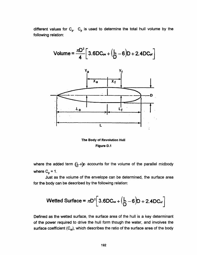
different values for Cp. C is used to determine the total hull volume by the
following relation:
Volume= ' [3.6DC.a + - 6)D + 2.4DC-]4 YVV·1\ - D J · ~V~
The Body of Revolution Hull
Figure D.1
where the added term (-6)D accounts for the volume of the parallel midbody
where Cp = 1.
Just as the volume of the envelope can be determined, the surface area
for the body can be described by the following relation:
Wetted Surface = nzD2[3.6DCsa + (- 6)D + 2.4DCf]
Defined as the wetted surface, the surface area of the hull is a key determinant
of the power required to drive the hull form though the water, and involves the
surface coefficient (Csf), which describes the ratio of the surface area of the body
192
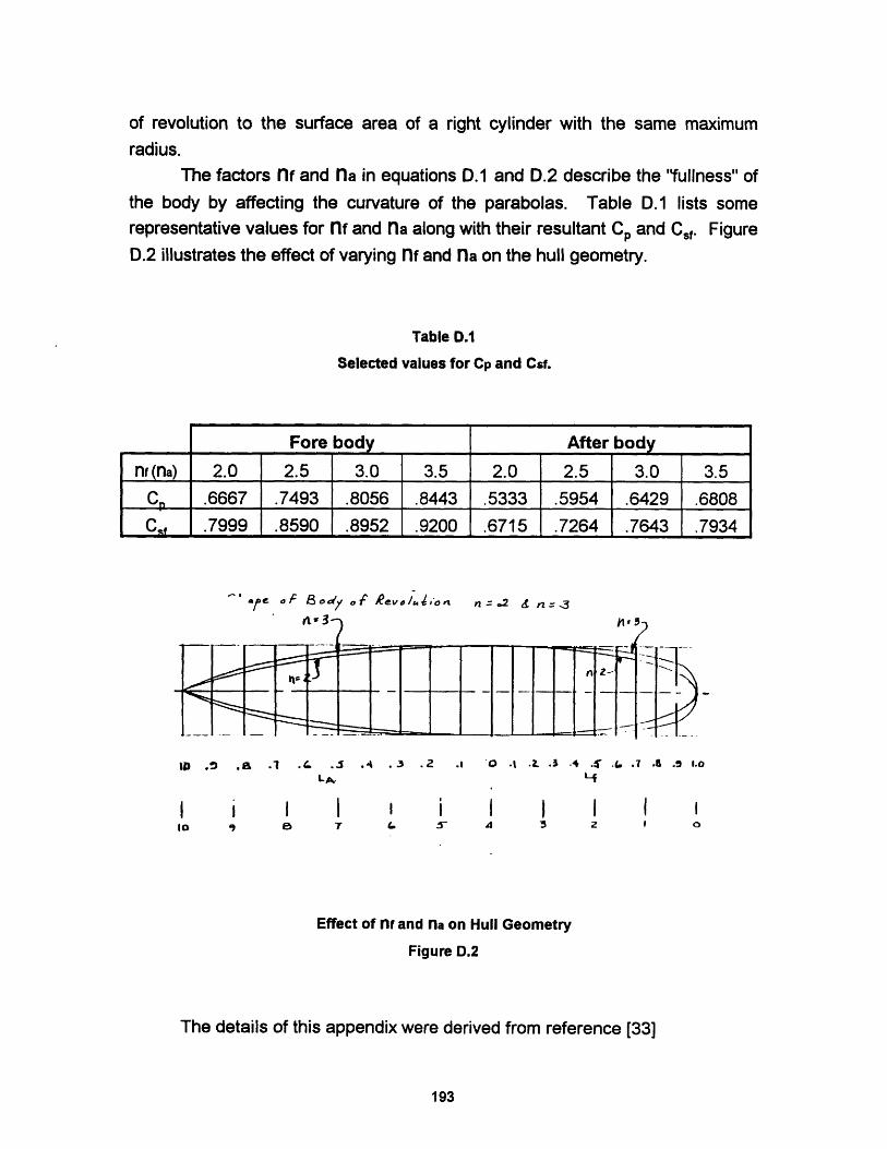
of revolution to the surface area of a right cylinder with the same maximum
radius.
The factors nf and na in equations D.1 and D.2 describe the "fullness" of
the body by affecting the curvature of the parabolas. Table D.1 lists some
representative values for nf and na along with their resultant Cp and Csf. Figure
D.2 illustrates the effect of varying nf and na on the hull geometry.
Table D.1
Selected values for Cp and Csf.
Fore body
2.0 2.5 3.0 3.5
.6667 .7493 .8056 .8443
.7999 .8590 .8952 .9200
After body
2.0 2.5 3.0 3.5
.5333 .5954 .6429 .6808
.6715 .7264 .7643 .7934
A' f Od Yf /C vo/,on nz. 2 = n ,3
tPo .a .1 .1 . .2 .40 t .3 A .: .t .t .9 .oLA. '4
I i I I I I I i I I IIa 4 0 r 7 L 5 4 5 2 Z 0
Effect of nf and na on Hull Geometry
Figure D.2
The details of this appendix were derived from reference [33]
193
n (na)
CP
Cs
._ , _ I w

(Blank Reverse)
194

APPENDIX E
VOLUME DATA
E.0 OVERVIEW
This appendix contains the details of the volume estimates used in
SUBSIZE. The volume data is based on the thesis by Stenard [61] which wasfurther analyzed by Professor J. Reed for presentation in a special submarine
design course at the Massachusetts Institute of Technology during the
Independent Activities Period, January 1994. Table E.1 summarizes the volume
data form Stenard. A discussion of the various factors chosen for the model
follows:
E.1 FACTOR ANALYSIS
To build the submarine model, estimates of ship volumes must be made.
Trends in this data must then be evaluated to develop parametrics from which
predictions of submarine attributes can be made. These parametrics form the
basis of the volume analysis below.
--- Mobility Volume
Reference [53] analysis of Stenard's data yields the parametric curve
shown in Figure E.1. With an estimate of SHP for the baseline ship of 5000
SHP, a mobility density diesel electric (PDE) of 6.7 ft3/SHP was selected.
Because this density accounts only for the diesel electric plant, the additional
volume for the AIP plant and any increased battery size from the baseline is
added to determine the overall AIP volume of mobility.
VAIP = SHP(pDE) + AVBattry + VAIP
195
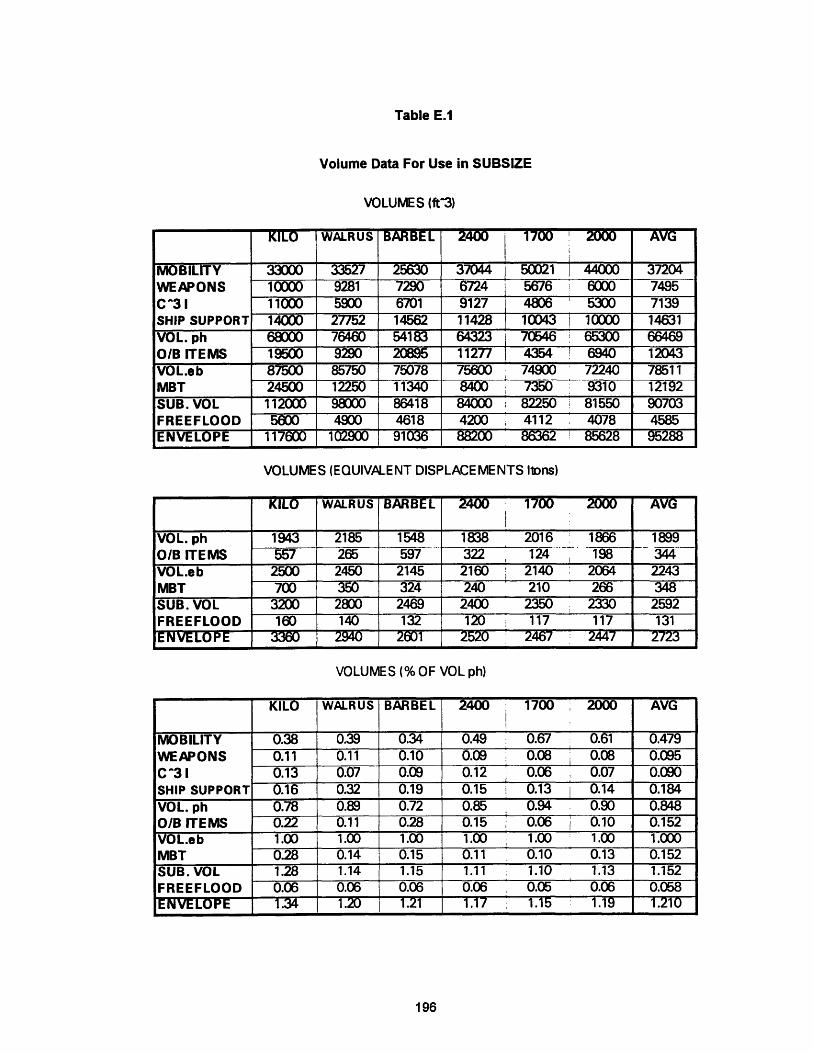
Table E.1
Volume Data For Use in SUBSIZE
VOLUMES (ft3)
KILO WALRUS BBEL 2 1700 200 AVG
MOBILITY 33000 33527 25630 37044 150021 i 44000 37204WEAPONS 10000 9281 7290 6724 5676 6000 7495
C^3 1 11000 5900 6701 9127 4806 5300 7139SHIP SUPPORT 14000 27752 14562 11428 10043 i 10000 14631
VOL. ph 68000 76460 54183 64323 70546 65300 66469
O/B ITEMS 19500 9290 20895 11277 4354 6940 12043VOL.eb 87500 85750 75078 75600 74900 72240 78511MBT 24500 12250 11340 8400 7350 9310 12192
SUB. VOL 112000 98000 86418 84000 82250 81550 90703FREEFLOOD 5600 4900 4618 4200 ' 4112 4078 4585ENVELOPE 117600 102900 91036 88200 86362 85628 95288
VOLUMES (EQUIVALENT DISPLACEMENTS lions)
KILO WALRUS BARBEL 2400 1700 2000 AVG
VOL. ph 1943 2185 1548 1838 2016 1866 1899
O/B ITEMS 557 265 597 322 124 198 344
VOL.eb 2500 2450 2145 2160 2140 2064 2243
MBT 700 350 324 240 210 266 348SUB. VOL 3200 2800 2469 2400 2350 2330 2592FREEFLOOD 160 140 132 120 117 117 131ENVELOPE 3360 2940 2601 2520 2467 244 7 2723
VOLUMES (% OF VOL ph)
KILO WALRUS BARBEL 2400 1700 2000 AVG
MOBILITY 0.38 0.39 0.34 0.49 0.67 0.61 0.479
WEAPONS 0.11 0.11 0.10 0.09 0.08 0.08 0.095C^3 1 0.13 0.07 0.09 0.12 0.06 0.07 0.090SHIP SUPPORT 0.16 0.32 0.19 0.15 0.13 i 0.14 0.184
VOL. ph 0.78 0.89 0.72 0.85 0.94 0.90 0.848O/B ITEMS 0.22 0.11 0.28 0.15 0.06 1 0.10 0.152VOL.eb 1.00 1.00 1.00 1.00 1.00 1.00 1.000MBT 0.28 0.14 0.15 0.11 0.10 0.13 0.152SUB. VOL 1.28 1.14 1.15 1.11 1.10 1.13 1.152FREEFLOOD 0.06 0.06 0.06 0.06 0.05 0.06 0.058ENVELOPE 1.34 1.-- 1.21 1.17 1.15 1.19 1.210
196

to
8
P MOB;a
6
4
SHP.I
Mobility Density
Figure E.1
, I'll _U .UU4
0.003
; PRL
a p.L RL;i -b RL
0.002
0.001
05 10 15 20
0.008
' -~~ \ 0.006
a PTrTi; -b PT-1- 0.004
0.002
RL.I
Torpedo Tube and Reload Densities
Figure E.2
197
I
I
_ X l_!J: gJ~~~J- ;-- -
6
TT.l
_I _~~~~~~
I I~~~~~~.
-
_
--I
84

--- Weapons
The weapons volume is based on similar parametric relationships for
those weapons items that remain fixed in the ship, specifically the number of
torpedo tubes installed and the room set aside for rack storage of weaDons.
Figure E.2 above presents the parametric curves for the torpedo tube (PuT) and
reload (PRL) densities [53]. The densities are then multiplied against values set
down in the owners requirements.
Vweps = No. Torp. Tubes(p,) + No.Reloads(pR, )
For this model values of 0.0042 and 0.0036 respectively were selected.
--- C31 Volume
The volume selected for C31 , 5300 ft3, was that of the British Type 2000
submarine based on the desire to have a ship with similar weapons and sensor
capabilities.
--- Ship Support Volume
Four factors combine to provide input for this volume:
Attribute Factor
Area Berthing and Messing (Abm) 10*crew size
Area Storeroom (Asr) 8.5*mission length
Area Office Spaces (Aos) 120 + 0.6*crew size
Volume Auxiliaries (Va,,x) a function of the above plus Vph
198

These constants were selected based on design experience and requirements
for habitability, adjusted for the fact that diesel submarines are generally not as
spacious as nuclear powered ships. The areas above are converted to volumes
by three multiplicitive factors, 1.08 to account for added area for passageways,
1.12 to account for wasted space in the vicinity of the curved hull, and a
standard deck height of 7 feet. The values are based on proven submarine
designs.
--- Other Volumes
The volumes outside the pressure hull are also based on design
experience and the data presented by Stenard. For SUBSIZE, the following
factors were selected:
Outboard Margin (% Vph) 0.18
Volume Main Ballast Tanks (%Veb) 0.15
Volume Freeflood (%Veb) 0.06
199

(Blank Reverse)
200

APPENDIX F
WEIGHT DATA
F.0 OVERVIEW
This appendix contains the weight data base for SUBSIZE, Table F. 1, as
well as a discussion of the weight formulae presented by Stenard [61]. The
weight data was further adjusted by Professor J. Reed for presentation in a
special submarine design course presented at the Massachusetts Institute of
Technology during the Independent Activities Period, January 1994.
F.1 FACTOR ANALYSIS
In his thesis, Stenard developed parametric equations for ship weights,
based on the data in Table F.1. In general these equations were used with
some modifications
--- Structural Weight
Stenard gives the following relation for structural weight:
Wstr = {NSC[0.00055(Diving Depth *) + 0.15]}
*in meters
which is a function of diving depth, sizing the pressure hull to withstand the
pressure exerted by the sea. The formula was accepted with the factor 0.00055
changed to 0.00017 to allow the use of depth in feet.
--- Mobility Weight
Again Stenard gives a relationship which is accepted except that the
battery weight for the baseline submarine, 420.96 Itons, is substituted for the
battery weight factor
Wmob=0.572(# battery cells) + 2.1(SHP)0 64.
201

Table F.1Weight Data For Use in SUBSIZE
KILO WALRUS BARBEL 2400 1700 ! 2000 AVG
STRUCTURE 825 787 820 618 544 611 701MOBILITY 700 792 575 868 988 922 808
WEAPONS 78 48 53 60 42 59 57C^3 1 67 50 56 84 32 40 55SHIP SUPPORT 101 98 117 101 67 76 93A-1 1771 1775 1621 1731 1673 ! 1708 1713FIXED BALLAST 128 129 123 119 86 93 113A 1899 1904 1744 1850 1759 1801 1826VARIABLE LOAD 600 550 401 310 380 264 418NSC 2499 2454 2145 2160 2139 2065 2244MBT 700 350 324 240 210 266 348SUB DISPL. 3199 2804 2469 2400 2348 2331 348
WEIGHl'S (% OF A -1 Ions)KILO WALRUS BARBEL 2400 1700 2000 AVG
STRUCTURE 0.47 0.44 0.51 0.36 0.33 0.36 0.409MOBILITY 0.40 0.45 0.35 0.50 0.59 0.54 0.471WEAPONS 0.04 0.03 0.03 0.03 -- 0.03 0-- 0.033C 3 1 0.04 0.03 0.03 0.05 0.02 0.02 0.032SHIP SUPPORT 0.06 0.06 0.07 0.06 i 0.04 0.04 0.055A-1 1.00 1.00 1.00 1.00 i 1.00 1.00 1.000FIXED BALLAST 0.07 0.07 0.08 0.07 0.05 0.05 0.066A 1.07 1.07 1.08 1.07 1 1.05 1.05 1.066VARIABLE LOAD 0.34 0.31 0.25 0.18 | 0.23 0.15 0.243NSC 1.41 1.38 1.32 1.25 1.28 , 1.21 1.309MBT 0.40 0.20 0.20 0.14 0.13 0.16 0.202SUB DISPL. 1.81 1.58 1.52 1.39 1.40 1.36 0.202
WEIGHTS (% OF NSCQKILO WALRUS BARBEL 2400 1700 2000 AVG
STRUCTURE 0.33 0.32 0.38 0.29 0.25 0.30 0.312MOBILITY 0.28 0.32 0.27 0.40 0.46 0.45 0.364WEAPONS 0.03 0.02 0.02 0.03 002 0.03 0.025C^3 1 0.03 0.02 0.03 0.04 0.01 0.02 0.024SHIP SUPPORT 0.04 0.04 0.05 0.0305 0.04 0.042A-1 0.71 0.72 0.76 0.80 0.78 0.83 0.766FIXED BALLAST 0.05 0.05 0.06 0.06 004 0.05 0.050A 0.76 0.78 0.81 0.86 0.82 0.87 0.817VARIABLE LOAD 0.24 0.22 0.19 0.14 0.18 0.13 0.183NSC 1.00 1.00 1.00 1.00 , 1.00 1.00 1.000MBT 0.28 0.14 0.15 0.11 0.10 0.13 0.152SUB DISPL. 1.28 1T.14 1.15 1.11 i 1.10 1.13 0.152
CV3 (WEtC 0.0067 0.0054 0.0077 0.0125 0.0056 0.0067 0.0074
202
As was the case for mobility volume, the overall mobility weight is further
adjusted to account for AIP weight and the change in battery weight
Wmob = Battery Weight + 2.1(SHP)"6 + AWBattery + WAP.
--- Weapons Weight
The following formula for weapons weight, based on the number of
torpedo tubes and a factor for the size of the weapons spaces is given and
accepted:
Wweps = [0.002(Vweps) + 6(No. Torp Tubes) + 5]
-- C31 Weight
Here Stenard gives a formula based on the volume of the C31 space:
0.00836 (Volume C31)
For SUBSIZE, a more traditional approach, that being a weight for C31 based on
NSC is taken, with the following factor taken developed from Stenard's data:
WC3, = 0.025(NSC)
--- Ship Support Weight
Again the parametric relationship presented by Stenard is used:
Ws = 0.0336 (NSC) + 0. 4(Crew Size).
--- Other Weights
The remaining weights that make up NSC are margins, based on
historical trends. These values become real numbers in the later stages of
design as detailed design is conducted and better estimates for these values are
obtained. For SUBSIZE, an initial value of 0.05 was selected for the lead margin
which is consistent with Table F. 1. The value of variable load should total to be
203
about 0.18 of NSC, but as explained in Chapter 6, fuel is included in the variable
load weight, thus variable load must now consider the impact of AIP. During the
validation of the model, it was observed that selecting a value for variable load
fraction equal to 0.05 would yield a final variable load fraction of about 0.18.
204

APPENDIX G
SNORKEL POWERING
G.0 OVERVIEW
Chapter 6 provided the required formula constants applied to the
hydrodynamic powering equations, which are well established. This appendix
focuses on the method used to determine the required snorkel power for the
submarine
G.1 PROCEDURE
When operating near the surface but not broached, ship powering is still
governed by the effects of a body of revolution hull moving through a fluid.
However due to the body's proximity to the surface, the additional effects of
making a disturbance on the free surface must be considered. As in surface
ship powering relationships, this additional power is a function of the Froude
Number for the ship, determined by:
1.69(Speed in knots)
/32.2 (Length)
This value is then used to enter Figure G.1, along with a ratio (h/L) to obtain a
chart number which is proportional to the wave making resistance of the hull. In
the ratio, "L" represents the length of the body of revolution while "h" is distance
from the center of the body of revolution to the surface of the fluid, which is also
illustrated in Figure G.1 this chart number is then applied to the following
relationship to obtain the wave resistance coefficient:
Chart No.
4( - k2)( ) 2
Cwave is then converted to SHP by the relation:
SHPwaVe = 8.72(WS)(Cw.).
205
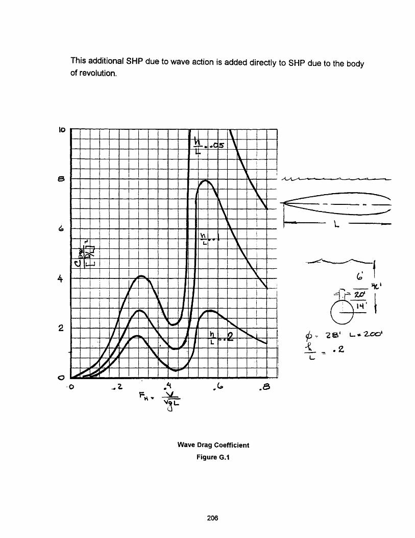
This additional SHP due to wave action is added directly to SHP due to the bodyof revolution.
- -- -- -- --1 -- -- - - -- - I ~ ~ i , \ ~ - - - -
t _ TIIII± _Z,~ i ~ - - _, __ _ : : -- _ _ I
i,! i iT I 1 \: _X_
_ T/ t 11 I[ i ri 1 X
//,/ \ -- ./ 'Z / , N ~ ,d' I .!~~~~~~~~~~. .
-o
L_
2-IV I
V
i- e L 00'.t .2.
. 6~~t
.Gr 4w _ _
V3 L
Wave Drag Coefficient
Figure G.1
206
10
4
2
0

APPENDIX H
DATA TABLES
This Appendix contains the data tables to support the results presented in
Chapter 8.
Compare Plants at 25 day enduranceFigure 8.2
PLANT LENGTH LOD NSC SHP AIP.:::?ALOX 234.83 7.58 3142.14 4479.78 410.34
i CBC 274.12 8.84 3842.31 5146.19 478.56CCD 330.32 10.66 4845.22 6084.74 575.3
iMCFC"- 201.35 6.5 2545.97 3903.28 351.69- PEM 202.35 6.53 2564.36 3920.66 353.45
i::i::STRLNG: 327.71 1057 4798.36 6041.43 570.82
207
Figure 8.1NSC NSC
(Itons) (Itons)
BASELINE 2325 2316
PEM - 25 day 3048 2804endurance
PEM - 35 day 3207 3316endurance
ALOX - 25 day 3449endurance
ALOX - 35 day 4544endurance
Differenc
0
-8
3
-1
18
t
__
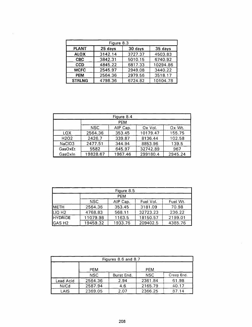
Figure 8.3PLANT 25 days 30 days 35 daysALOX 3142.14 3727.37 4503.83CBC 3842.31 5010.15 6740.92CCD 4845.22 6817.33 10294.86MCFC 2545.97 2949.08 3440.22PEM 2564.36 2979.56 3518.17
STRLNG 4798.36 6724.82 10104.78
PEM
NSC AIP Cap. Ox Vol. Ox Wt.LOX 2564.36 353.45 10179.47 155.75H202 2426.7 339.87 8136.44 102.58
NaCI03 2477.51 344.94 8853.96 139.5GasOxEt 5582 645.97 32742.89 967GasOxln 19828.67 1967.46 299180.4 2945.24
Figure 8.5PEM
NSC AIP Cap. Fuel Vol. Fuel Wt.METH 2564.36 353.45 3181.09 70.98LIQ H2 4768.83 568.11 32723.23 236.22HYDRIDE 11079.98 1163.5 18150.57 2199.01GAS H2 19459.32 1933.76 209402.5 4385.76
Figures 8.6 and 8.7
PEM PEM
NSC Burst End. NSC Creep End.
Lead Acid 2564.36 2.94 2361.84 61.98Ni/Cd 2587.94 4.6 2165.79 40.17LAIS 2369.05 2.07 2366.25 87.14
208
Figure 8.4
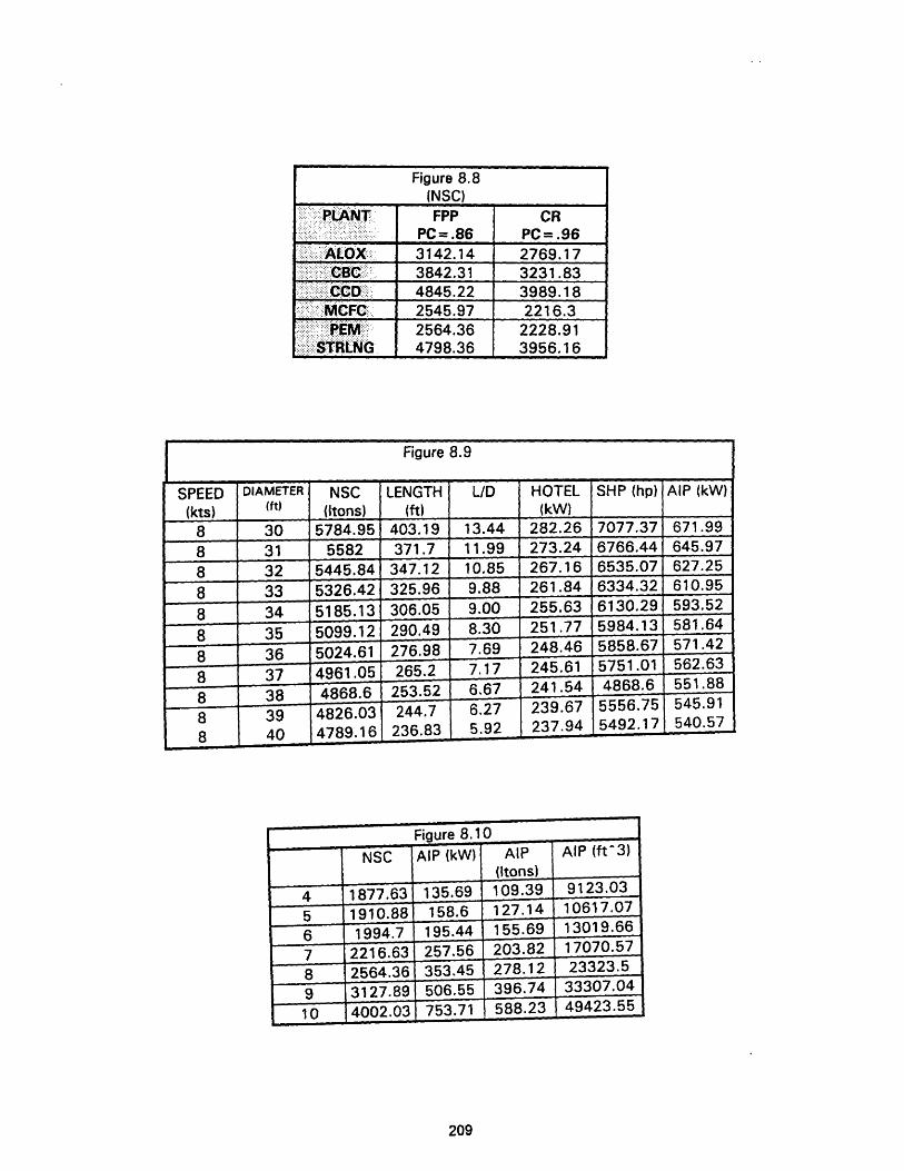
SPEED(kts)
88888
HOTEL(kW)
282.26273.24267.16261.84255.63
...... Figure 8.91~~DAEE 1~~~~~~~~~~~~~~H h)AP(W
DIAMETER(ft)
3031323334
AIP (kW)
671.99645.97627.25610.95593.521 A
SHP (hp)
7077.376766.446535.076334.326130.29C;OQA 1'
LID
13.4411.9910.859.889.00H-t
88888
5024.614961.054868.64826.03._pI A.
36373839. 1
Q
LENGTH(ft)
403.19
371.7347.12325.96306.05.... A
276.98265.2
253.52244.7"n~ 0a
209
_ V-4
7.176.676.27r Qa9
_L14
245.61241.54239.67937.94
. ~.U5751.01
4868.65556.755492.17
I _ _ . A .
.... bA
551.88545.91540.57
NSC(Itons)
5784.955582
5445.845326.425185.13_nQQ _') I £.
Figure 8.8(NSC)
:PLAiNT FPP CR::.:::: :: ........;;. cR
.:::.:-:.:.: - .: .. :: ::: PC= .86 PC= .96igiiALOX:: 3142.14 2769.17
: . :BC 3842.31 3231.83::CiCDii .. 4845.22 3989.18
MCFC:. 2545.97 2216.3
.... .................- 2564.36 2228.91: STRLNG 4798.36 3956.16
Figure 8.10 -
NSC AIP (kW) AIP AIP (ft'3)
(Itons)
877.63 135.69 109.39 9123.03310.88 158.6 127.14 10617.07
994.7 195.44 155.69 13019.66216.63 257.56 203.82 17070.57564.36 353.45 278.12 23323.5
127.89 506.55 396.74 33307.04002.03 753.71 588.23 49423.55
.
_ _
Jo ;V. - JJV. _s
_ A n A n A e Ic Ir 7 1 . I1 .f'll-.
. .
.
l, . . ..-.
_l
40 4/vY. ID LjU.O I a W--.V -- - ...._ _ l
U .v - r
;Iu U-3 l I. 3Uvo, , jK :JHasnQa 1 )Qn an �
DO0.-/ ll.fLfj4.417 i 4
5751.01 562.63

(Blank Reverse)
APPENDIX I
COMPUTER PROGRAM
1.0 OVERVIEW
This appendix contains the computer code, written in Turbo C++, using
Borland Turbo C++ 3.0 and contains the following sections:
Section Page No.
1.1 Main Program - SUBSIZE.CPP 212
1.2 Header File - AIP.H 228
1.3 Powering Functions - POWERING.CPP 229
1.4 Printer File - PRINTER.CPP 233
1.5 AIP Sizing Functions and Plant Input Files - AIPSIZE.CPP 235
1.6 Sample Output 243
211
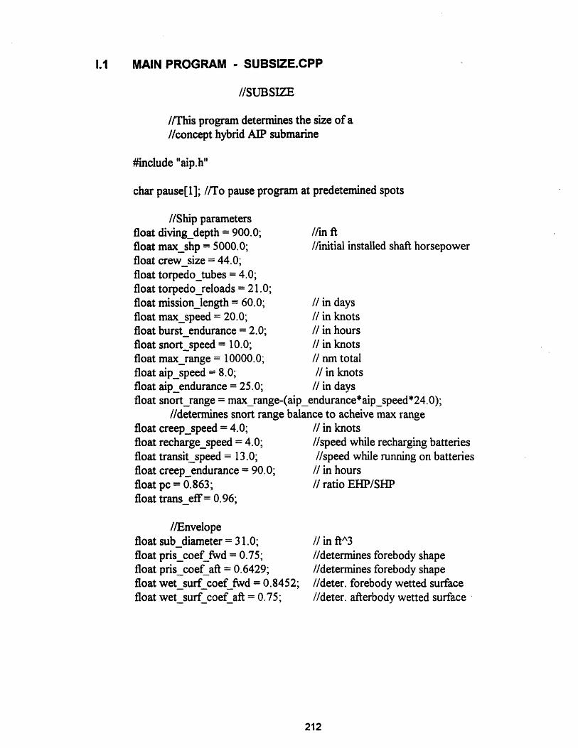
1.1 MAIN PROGRAM - SUBSIZE.CPP
//SUBSIZE
//This program determines the size of a//concept hybrid AIP submarine
#include "aip.h"
char pause[l]; //To pause program at predetemined spots
//Ship parametersfloat diving_depth = 900.0;float max_shp = 5000.0;float crewsize = 44.0;float torpedo_tubes = 4.0;
//in ftI/initial installed shaft horsepower
float torpedo_reloads = 21.0;float mission_length = 60.0; I in daysfloat max_speed = 20.0; I in knotsfloat burstendurance = 2.0; II in hoursfloat snort_speed = 10.0; I in knotsfloat max_range = 10000.0; // nm totalfloat aip_speed = 8.0; // in knotsfloat aip endurance = 25.0; // in daysfloat snort-range = max_range-(aip_endurance*aip_speed*24.0);
//determines snort range balance to acheive max rangefloat creep_speed = 4.0; I in knotsfloat recharge_speed = 4.0; //speed while recharging batteriesfloat transitspeed = 13.0; //speed while running on batteriesfloat creep_endurance = 90.0; I in hoursfloat pc = 0.863; // ratio EHP/SHPfloat transeff= 0.96;
//Envelopefloat subdiameter = 31.0;float pris_coef fwd = 0.75;float pris_coefaft = 0.6429;float wetsurf coef fwd = 0.8452;float wetsurf coef aft = 0.75;
I in ft^3
//determines forebody shape//determines forebody shape//deter. forebody wetted surface//deter. afterbody wetted surface
212

floatfloatfloatfloatfloatfloatfloatfloatfloatfloat
//Margins and weights/volumesvolume c cubedi = 5300.0;fixed_ballast_margin = 0.05;variable_load_margin = 0.05;c cubed i factor = 0.025;mobility_density = 6.7;torpedo_tube_density= 1/(.0042);torpedoreload_density = 1/(.0036);outboard_margin = 0. 18;mbt_margin = 0. 15;freeflood_margin = 0.06;
//Batterychar batterytype[30] = "Lead Acid";float batt wt = 76.4;float batt vol = 800.0;float batt_two hrcapacity = 1600.0;float batt_eighty_hr_capacity = 2645.5;float batt_cap_transit = 2455.6;float num batt init = 5.51;float couleff= 0.9;
//char battery_type[30] =" LAIS";I/float battwt = 3.69;//float battvol = 72.24;//float batt_two hr capacity = 369.0;//float batt_eighty_hr_capacity = 858.0;I/float batt_cap_transit = 0.0;//float num batt init = 23.89;//float couleff= 1.0;
//char batterytype[30] =" Ni/Cd";//float batt wt = 38.0;I/float batt vol = 670.0;//float batt_two hr capacity = 1201.0;//float batt_eighty_hr_capacity = 1270.0;//float batt_cap_transit = 0.0;I/float numbattinit = 10.78;I/float couleff= 0.9;
I in ft^3//deter. initial lead margin//estimate of variable load fraction//estimate of C^3I fraction of nsc//in ftA3/hpI/in ftA3/TT
//in ftA3/reload//deter. otbd item vol.
//deter. reserve buoyancy//deter. freeflood vol.
I in Itons// in ft^3
// in kW-hrI in kW-hrI/in kW-hrs
//effic. of extracting battery energy
//in Itons// in ft^3
I in kW-hrI in kW-hr
//effic. of extracting battery energy
I in ItonsI in ftA^3
//in kW-hrI in kW-hr
//effic. of extracting battery energy
extern float batt_endur_burst, batt_endurcreep;extern float num_batt;
213

float volume_weapons; //in ft^3float volume_mobility; //in ft^3
float volume_aux; //in ftA3
float volumeship_support; //in ftA^3
float volumepressure_hull; //in ftA3float volumeoutboard; //in ft^3
float volume_everbuoyant; //in ftA 3
float volume_main_ballast_tank; //in ftA3
float volume_submerged; //in ftA3float volume_freeflood; //in ft^3float volume_envelopereq; //in ftA^3
float weight_structure; //ltonsfloat weight_mobility; //ltonsfloat weight_c_cubed_i; /ltonsfloat weight_weapons; //ltonsfloat weight_fixed_ballast; //ltonsfloat weight_ship_support; //ltonsfloat weight_variable_load; //ltonsfloat nsc; //ltonsfloat old_nsc; //ltonsfloat sub_length; //feetfloat speed; //knotsfloat wet_surf; //ft^2
//Declarations from aip header files:float ehp_aip;float shp_aip;float reqd_capacity_aip; //in kWfloat plant_wt;float plant_vol;float reformer_wt;float reformer_vol;float oxidant_wt;float oxidant_vol;float fuel_wt;float fuel_vol;float other_wt;float other_vol;float product_wt;float product_vol;extern float lox_wt;extern float lox_vol;
214
char plant_type[30];char reformer[5];char oxidant_type[30];char fuel_type[30];char other_type[30];char product_mgmt[30];char breathing_oxygen[5];
//Declarations from powerOfloat nusw = 1.2817/100000.0;float reynolds_num;float corr allow = 0.0004;float frict_coef;float residcoef,float area sail = 800.0;float coef_drag_sail = 0.009;float resist_bridge;float resist_app;extern float ehp, shp; //effective and shaft horsepower
//Declarations from hotel()float hotel_load;
floatfloatfloatfloat
//Declarations from diesel()dieselsfc = 0.55;dieselmech eta = 0.90;fuelallow= 0.8;bunker_fuel;
/ #/hp-hr
// % fuel use during mission
//Declarations from indesc(float ehp_recharge;float shp_recharge;float time_recharge;float batt_endur_transit;float indesc_ratio;float shp_transit;float ehp_transit;float soa;float coef wave;float shpwave;
215
externexternexternexternexternexternextern

#include <iostream.h>#include <math.h>#include <iomanip.h>#include <fstream.h>#include <string.h>
float pi = 4*atan(1.0);float kl = 6.0-3.6*pris_coef aft
-2.4*pris_coef_fwd;float k2 = 6.0-3.6*wet surf coef aft
-2.4*wetsurf coef fwd;
float aip_vol = 0.0;float aip_wt = 0.0;float delta_batt_wt = 0.0;float deltabattvol = 0.0;
mainO
{cout « setiosflags(ios: :fixed) <<setprecision(2);
//defines pi
//for hull shape calculations
//for wetted surf calculations
//initally zero for baseline calc.//initally zero for baseline calc.//initally zero for baseline calc.//initally zero for baseline calc.
//Estimate required volume of the submarine with//volume function.
volume();
//Determine envelope dimensions for a body of revolution//based on the estimated volume and curve factors.
envelopeO;
//Estimate the required weight of the submarine with//weight function
weight0;
//This loop adds hull length if weight limited//and is skipped if volume limited.
wt_limitO;
//This loop adds lead weight if volume limited//and is skipped if weight limited.
vllimitO;
216
//Determine the power required to push the body of revolution.
speed = max_speed;powerO;max_shp = shp;
//Determine the propulsion power required while snorting//for the body of revolution.
snortO;
//Determine the hotel load for the ship.hotelO;
//Determine diesel fuel required to transit the required snort distance.diesfuel();
//Determine battery size difference from the baseline.battdelt0;
//Determine battery endurance.battendr();
//User select the AIP plant to evaluate.
int type;cout << "\nSelect AIP type:\n";cout << "PEM F C = l\n";cout << "Molten Carbonate F C = 2\n";cout << "Al Ox Cell = 3\n";cout << "Closed Diesel = 4\n";cout << "Closed Brayton = 5n";cout << "Closed Stirling = 6\n";cin>> type;switch( type)
{
case 1: pemdeclO; break;case 2: mfcdecl(); break;case 3: aludeclO; break;case 4: ccddeclO; break;case 5: cbcdecl(; break;case 6: strdeclO; break;default:cout << "invalid entry shouldbreak;
}
be integer between 1 and 6\n";
217

//Determine the size of the AIP plant.aipsizeO;
//Now that the AIP plant has been sized,//rerun weights and volumes.
do{
old_nsc=nsc;
//Rerun volume estimate.volumeO;
//Rerun envelope dimensions.envelopeO;
//Rerun weight estimate.weights;
//This loop grows the envelope volume if weight//limited and is skipped if volume limited.
wt_limitO;
//This loop adds lead weight if volume limitedHand is skipped if weight limited.
vl_limitO;
//Determine the propulsion power required for/la given speed for the body of revolution.
speed = maxspeed;power0;max_shp = shp;
//Determine the propulsion power required while//snorting for the body of revolution.
snort();
//Determine the hotel load for the ship.hotelO;
//Determine diesel fuel required.diesfuelO;
218

//Determine battery size difference from the baseline.
battdelt0;
//Determine battery endurance.battendr0;
//Redetermine the AIP plant size.aipsize0;
//Determine indescretion ratio parameters.indesc0;
while ((nsc-old_nsc)/nsc>O.0 1);
//Prepare Screen Output
cout << "\t\t\t****AIP SIZING PROGRAM OUTPUT****\n";cout << "\t\t\t\t INPUT DATA\n";cout << "\tRange: Total Ship Range (nm)\t\t\t\t"<<maxrange<<'\n';cout << "\t\tSnort ( "<<snortspeed<<" kts (nm)\t\t\t\t"
<<snort range<< 'n';cout << "\t\tSubmerged @ "<<aip_speed<<" kts AIP (days)\t\t\t"
<<aip_endurance<< '\n';cout << "\t\tSubmerged creep @ "<<creep_speed
<<" kts on battery (hours)\t"<<batt_endur_creep<< '\n';cout << "\t\tSubmerged burst @ "<<max_speed
<<" kts on battery (hours)\t"<<batt_endur_burst<< '\n';cout << "\t\tSubmerged transit ( "<<transitspeed
<<" kts on battery (hours)\t"<<batt_endur_transit<< '\n';cout << "\t\tRecharge time @ "<<recharge_speed<<" kts (hours)\t\t\t"
<time_recharge<<'\n';cout << "\t\tSOA (kts) "<<soa<< "\tIndescretion Ratio\t"
<<indesc ratio<< '\n'<< \n';
cout << "\tDiving Depth (ft):\t"<<diving_depth<<"\tCrew Size:\t"<<crew size<< 'n';
cout << "\tTorpedo Tubes:\t\t"<<torpedo_tubes<<"\tReloads:\t"<<torpedoreloads<< '\n';
cout << "\t\t\t\t MARGINS\n";cout << "\tFixed Ballast (% NSC):\t\t"<<setprecision(3)
<<fixed _ballast margin<<setprecision(2)<<"\tVariable Load (% NSC):\t"<<variable_load_margin<< '\n';
cout << "\tOutboard Items (% Vph):\t\t"<<outboard_margin<<"\tRes. Buoyancy (% Veb):\t"<<mbt_margin<< 'n';
cout << "\tFreeflood Volume (% Veb):\t"<<freeflood_margin<< '\n';
219

cout << "\t\t\t\t ENVELOPE\n";cout << "\tLength (ft):\t"<<sub_length<<"\t\tDiameter (ft):\t"
<<sub_diameter<<"\tL/D:\t"<<sub_length/sub_diameter<< \n';cout << "\tCpf:\t"<<setprecision(4)<<pris_coef fwd<<"\tCpa:\t"
<<pris_coef_aft<<"\tCwsf:\t"<<wet_surf_coef_fwd<<"\tCwsa:\t"<<wet_surf_coef_aft<<setprecision(2)<< '\n';
i/cin >>pause;
cout << "\t\t\t\t VOLUMES (ft^3)\n";cout << "\tWeapons:\t"<<volume_weapons<<"\t\tMobility:\t"
<<volume_mobility<< \n';cout << "\tShip Support:\t"<<volume_ship_support<< "\tCA3I:\t\t\t"
<<volumec cubed i<< \n';cout << "\tPressure Hull:\t"<<volumep ressure_hull<<"\tOutboard:\t\t
<<volume outboard<< '\n';cout << "\tEverbuoyant:\t"<<volume_everbuoyant
<<"\tMain Ballast Tanks:\t"<<volumemainballasttank<< '\n';cout <<"\tSubmerged:\t"<<volume_submerged<< "\tFreeflood:\t\t"
<<volume freeflood<< '\n';cout <<"\tEnvelope:\t"<<volume_envelope_req<< '\n';
cout << "\t\t\t\t WEIGHTS (Itons)\n";cout << "\tStructure:\t"<<weightstructure<<"\t\tMobility:\t\t"
<<weight_mobility<< '\n';cout <<"\tWeapons:\t"<<weight_weapons<< "\t\tCA3I:\t\t\t"
<<weightc_cubed_i<< n';cout <<"\tShip Support:\t"<<weight_ship_support
<<"\t\tFixed Ballast:\t\t"<<weight_fixed_ballast<< '\n';cout << "\t#Variable Load:\t"<<weight_variable_load
<<"\t\tNormal Surf. Condition:\t"<<nsc<< '\n';
cout << "\t\t\t\t MOBILITY\n";cout << "\tBattery Type:\t"<<battery_type<<"\tNumber of Batteries\t"
<<numbatt<< \n';cout <<"\tBattery: Weight(lton):\t"<<num_batt*batt_wt
<<"\tVolume(ftA3):\t\t"<<num_batt*batt_vol<< '\n';cout <<"\tCapacity(kW-hr ( 2hr rate):\t"
<<num_batt*batt_two hrcapacity<< '\n';cout <<"\tPropulsive Coeff:\t"<<pc<<"\tInstalled SHP: \t\t"
<<max_shp<< '\n';cout <<"\tHotel Load (kW):\t"<<hotel_load
<<"\t#Bunker Fuel (Itons):\t"<<bunker_fuel<< '\n';//cin >> pause;
220

cout << "\t\t\t\t AIP\n";cout << "\tAIP Plant Size (kW):\t"<<reqd_capacity_aip<<'\n';cout << "\tType:\t\t"<<plant_type<<"\tWeight(ltons):\t"<<plant_wt
<<"\tVolume(ftA3):"<<plant_vol<< \n';cout << "\tReformer:\t"<<reformer<<"\tWeight(ltons):\t"<<reformer_wt
<<"\tVolume(ftA3):"<<reformer_vol<< \n';cout << "\tOxidant:\t"<<oxidant_type<<"\t#Weight(tons):\t"
<<oxidant_wt<<"\tVolume(ftA3):"<<oxidant_vol<< '\n';cout << "\tBreath. LOX:\t"<<breathing_oxygen<<"\t#Weight(ltons):\t"
<<lox_wt<<"\tVolume(ft^3):"<<lox_vol<< \n';cout << "\tFuel: \t"<<fuel_type<<"\t#Weight(ltons):\t"<<fuel_wt
<<"\tVolume(ftA3): "<<fuel_vol<< n';cout << "\tOther: "<<other_type<<"\t#Weight(ltons):\t"<<other_wt
<<"\tVolume(ft3): "<<other_vol<< '\n';cout << "\tCosworth:\t"<<product_mgmt<<"\tWeight(ltons):\t"
<<product_wt<<"\tVolume(ftA3 ):"<<product _vol<< '\n';cout << "\tTotals:\t\t\tWeight(ltons):\t"<<aip wt
<<"\tVolume(ftA^3): "<<aip_vol<< '\n';
//Send data to printer#include "printer.cpp"
return 0;
}
//**********END OF MAIN PROGRAM SUBSIZE***********
//DIESFUEL
diesfuelO
{
//This subroutine calculates the amount of diesel fuel//required to transit snort range at periscope depth.
extern float shp_snort;
bunker_fuel = (snort_range*diesel_sfc*(shp_snort+ 1.34*hotel_load))/(2240.0*fuel_allow*trans_ef* snort_speed);
return (0);
}
//**END OF DIESFUELO**
221

//ENVELOPE
envelope0
//This function calculates a body of revolution length given//the envelope displacement and a diameter.
sub_length = sub_diameter*(kl+((140.0*volume_envelope_req/35)/(pi*pow(subdiameter,3))));
return (0);
//**END OF ENVELOPE()**
//HOTEL
hotelO
{//This subroutine calculates hotel load based on//volume estimates.
hotel_load = 15.0+(1.5*volume_mobility+4.0*volume_c_cubed_i+1.5 *volume_ship_support+volume_weapons)/1000.0;
return (0);
}//**END OF HOTEL()**
222

//INDESCOindescO{
//This subroutine calculates the indiscretion ratio for an//assumed snort speed while recharging batteries
//calculate the shp at recharge speedspeed = recharge_speed;power0;shp_recharge = shp;coef wave = 0.2/(4.0*((sublength/sub_diameter)- 1.3606)*
pow(sublength/sub_diameter,2));//0.2 determined from Jackson notes pg. 6-23A
shp_wave = 8.72*wetsurf*coef_wave;shp_recharge = shp_recharge+shp_wave;
//calculate the hotel load during rechargehotel();
//calculate time to rechargetime_recharge = ((num_batt*batt_cap_transit)*0.80)/
((3 .0*990.0-shp_recharge* 1.34+hotelload)*0. 80);
//calculate endurance on battery at transit speedspeed = transit_speed;power0;shp_transit = shp;batt_endur_transit = (num_batt*batt_cap_transit- 100.0)
*coul_eff*transeff/((shp_transit*0.746)+hotel_load);//-100 accounts for 100 kW-hrs consumed while preparing//for periscope depth operations.//Calculate indescretion ratio and speed of advance.
indesc_ratio = time_recharge/(time_recharge+batt_endur_transit+ 1.0);//+1.0 accounts for 1 hour of periscope depth preparationI/time with no distance travelled.
soa = (time_recharge*recharge_speed+batt_endur_transit*transit_speed)/(time_recharge+batt_endur_transit+ 1.0);
return(0);}
//**END OF INDESC0**
223
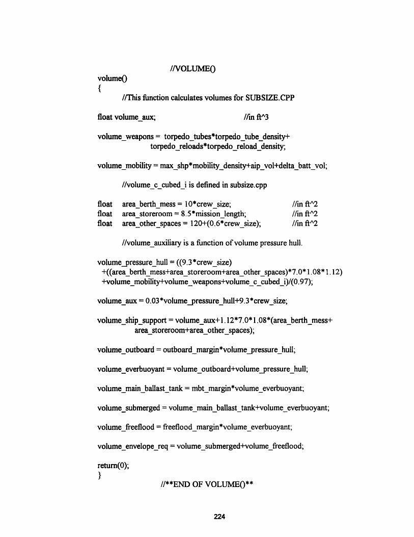
//VOLUMEOvolumeO
{
//This function calculates volumes for SUBSIZE.CPP
float volume_aux; /in ftA3
volume_weapons = torpedo_tubes*torpedo_tube_density+torpedo_reloads*torpedo_reload_density;
volume_mobility = maxshp*mobility_density+aip_vol+delta_batt_vol;
//volume_c_cubed_i is defined in subsize.cpp
float area_berth_mess = 10*crew_size; //in ft^2float area_storeroom = 8.5*mission_length; //in ft^2float area_other_spaces = 120+(0.6*crew_size); //in ft^2
//volume_auxiliary is a function of volume pressure hull.
volume_pressure_hull = ((9.3 *crew_size)+((area_berth_mess+area_storeroom+area_otherspaces)*7.0* 1.08* 1.12)+volume_mobility+volume_weapons+volume_ccubed i)/(0.97);
volume_aux = 0.03 *volume_pressure_hull+9.3 *crewsize;
volumeship_support = volume_aux+l.12*7.0*1.08*(area_berth_mess+area_storeroom+area_otherspaces);
volume_outboard = outboard_margin*volume_pressure_hull;
volume_everbuoyant = volume_outboard+volume_pressure_hull;
volume_main_ballast_tank = mbt_margin*volume_everbuoyant;
volume_submerged = volume_main_ballast_tank+volume_everbuoyant;
volume_freeflood = freeflood_margin*volume_everbuoyant;
volume_envelope_req = volume_submerged+volume_freeflood;
return(O);
}//**END OF VOLUME0**
224
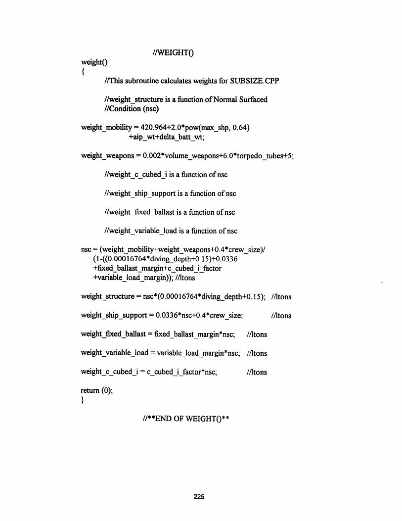
//WEIGHTOweightO
{
//This subroutine calculates weights for SUBSIZE.CPP
//weight_structure is a function of Normal Surfaced//Condition (nsc)
weight_mobility = 420.964+2.0*pow(max_shp, 0.64)+aip_wt+delta_batt_wt;
weight_weapons = 0.002*volume_weapons+6.0*torpedo_tubes+5;
//weight_c_cubed_i is a function of nsc
//weight_ship_support is a function of nsc
//weight_fixed_ballast is a function of nsc
//weight_variable_load is a function of nsc
nsc = (weight_mobility+weight_weapons+0.4*crew_size)/(1 -((0.0001 6764*diving_depth+0. 15)+0.0336+fixed_ballast margin+c _cubed _ifactor+variable_load_margin)); //ltons
weight_structure = nsc*(0.00016764*diving_depth+0.15); //ltons
weight_ship_support = 0.0336*nsc+0.4*crew_size; //ltons
weightfixed_ballast = fixed_ballast_margin*nsc; //ltons
weight_variable_load = variable_load_margin*nsc; //ltons
weight_ccubedi = c cubed i factor*nsc; //ltons
return (0);
}
//**END OF WEIGHT()**
225

//VLLIMITvllimitO{
//This function balances weights and volumes if//volume limited.
while (volume_everbuoyant/35>=nsc &&(volume_everbuoyant/35-nsc)/nsc>0.001)
{
while (volume_everbuoyant/35>=nsc &&(volume_everbuoyant/35-nsc)/nsc>0. 001){
fixed_ballast_margin = fixed_ballast_margin + 0.0004;
weight();}
return (0);
//**END OF VL_LIMIT()**
//WTLIMITwt_limitO
//This subroutine balances weights and volumes if//weight limited.
while (nsc>=volume_everbuoyant/3 5)
{
while (nsc>=volume_everbuoyant/35)
{
sub_length = sub_length+0. 1;volume_envelopereq = ((pi*pow(sub_diameter,3))/4)
*((sublength/sub_diameter)-k 1);
volume_everbuoyant = volume_envelopereq/( 1+mbt_margin+freefloodmargin);
}
226
//Recalcuate the volumes that changed on matching//weights and volumes.
volume_main_ballast_tank = mbt_margin*volume_everbuoyant;
volume_freeflood = freeflood_margin*volume_everbuoyant;
volume_submerged = volume_main_ballast_tank+volume_everbuoyant;
volume_pressure_hull = volume_everbuoyant/(1 +outboard_margin);
volume_ship_support =volume_pressure_hull - volume_mobility- volume_weapons-volume_c_cubed_i;
volume_outboard = volumepressure_hull*outboard_margin;
return (0);}
//**END OF WT_LIMIT0**
227
1.2 HEADER FILE - AIP.H
//program aip.h//function prototypes
int volume;int envelope0;int diesfuel0;int hotel0;int battendr;int battdelt0;nt power;int aipsize0;int weight0;int wt_limit();
int vl_limit0;int snort();int aludecl0;int cbcdecl();int ccddecl0;int mfcdeclO;int pemdecl0;int strdecl0;int indesc();
228
1.3 POWERING FUNCTIONS - POWERING.CPP
//POWERING.CPP#include <math.h>#include <fstream.h>#include <string.h>#include "aip.h"
float shp_batt_creep, ehp_batt_creep, batt_endur_creep;float batt_endur_burst, ehp_battburst, shp_batt_burst;float ehp,shp, num_batt;
extern float max_speed, speed, wet_surf, pi;extern float sub_diameter, sub_length, k2, reynoldsnum, nu_sw;extern float frict_coef, resid_coef, resist_bridge, area_sail;extern float coef_drag_sail, resist_app, corr_allow, pc, num_batt;extern float num_battinit, batt_two_hr_capacity;extern float batt_eighty_hrcapacity, coul_eff, trans_eff;extern float hotel_load, creep_speed, motor_eff, batt_endur_creep;extern float creep_endurance, batt_wt, delta_batt_vol;extern float delta_batt_wt, batt_vol, burstendurance;extern float coef_wave, shp_wave;
//Declarations from snort:float chart_number = 0.9; //obtained from Jackson notes pg. 6-23Afloat shp_snort, ehp_snort;extern float snortspeed;
//BATTDELTO
battdeltO{
//This subroutine calculates the change in battery size//from a baseline diesel electric lead acid battery.
float reqd_capacity_burst;float num_batt burst;float delta_batt_burst;float reqd_capacity_creep;float num_batt_creep;float delta_batt_creep;float delta_batt;
229
num_batt = num_batt init;
//Calculate battery delta based on burst speedspeed = max_speed;powerO;
ehp_batt_burst = ehp;shp_batt_burst = shp;
reqd_capacity_burst = burst_endurance*((shp_batt_burst*0.746)+hotel_load)/(coul_eff*trans_eff);
num_batt._burst = reqd_capacity_burst/batt_two_hr capacity;
delta_battburst = num_battburst - num_batt;//Calculate battery delta based on creep speed
speed = creep_speed;power0;
ehp_batt_creep = ehp;shp_batt_creep = shp;
reqd_capacity_creep = creep_endurance*((shpbatt_creep*0.746)+hotel_load)/(coul_eff*trans_eff);
num_batt_creep = reqd_capacity_creep/batt_eighty_hr_ capacity;
delta_batt creep = num_batt_creep - num_batt;
if (delta_batt_burst>delta_batt_creep)
{
delta batt = delta batt burst;
else
{
delta_batt = delta_batt_creep;}
num_batt = numbatt+deltabatt;delta_batt wt = deltabatt*batt wt;delta_batt vol = deltabatt*battvol;
return (0);
//**END OF BATTDELT(**
230

//BATTENDRO
battendrO{
//This subroutine calculates endurance on the//installed battery.
//Calculate burst endurance.speed = max_speed;power0;
ehpbattburst = ehp;shp_batt_burst = shp;
batt_endur_burst = num_batt*batt_two_hrcapacity*coul_eff*trans_eff/((shp_batt_burst*0. 746)+hotel_load);
//Calculate creep endurance.speed = creep_speed;power();
ehp_batt_creep = ehp;shp_batt_creep = shp;
batt_endur_creep = num_batt*batteighty_hr_capacity*couleff*trans_eff/((shp_batt_creep*0.746)+hotel_load);
return (0);
}
//**END OF BATTENDR()**
//POWER()
power(){
//This subroutine calculates the propulsive power required//for a given hull.
//User must designate what speed is to be used before calling//POWER0 by the following sequence:II speed = ???_speed;II power();
231
//Assumed seawater properties:
11
Temperature 59 deg F.rho: 1.9905 #-sec^2/ftA4.nu: 1.2817e-5 ftA2/sec.
wet_surf = pi*pow(sub_diameter,2)*(sub _length/sub_diameter-k2);
reynolds_num = (sub_length*speed* 1.6889)/nu_sw;frict_coef = 0.075/pow((logIO(reynoldsnum)-2),2);resid_coef= 0.000789/((sub_length/sub_diameter)-k2);resistbridge = area_sail*coef drag_sail;resist_app = sub_length*sub_diameter/1000.0;
ehp = 0.00872*pow(speed,3)* (wet_surf (fiict_coef+resid_coef+corr_allow)+resistbridge+resist_app);
shp = ehp/pc;
return (0);
}
//**END OF POWER()**
//SNORTsnort(){
//This subroutine calculates the propulsive power//required while snorting for a given hull.
speed = snort_speed;powerO;
ehp_snort = ehp;shp_snort = shp;
coef_wave = chart_number/(4.0*((sub_length/sub_diameter)- 1.3606)*pow(sub_length/sub_diameter,2));
shp_wave = 8.72*wet_surf*coef_wave;
shp_snort = shpsnort+shp_wave;
return(0);
}//**END OF SNORT()**
232

1.4 PRINTER FILE - PRINTER.CPP
ofstream prn("PRN");prn << setiosflags(ios: :fixed) <<setprecision(2);pm << "\t\t\t****AIP SIZING PROGRAM OUTPUT****"<< '\r';pm << "\t\t\t****AIP SIZING PROGRAM OUTPUT****\n\n";pm << "\t\t\t\t INPUT DATA\t\t"<<plant_type<<\n'<<'\n';pm << "\tRange: Total Ship Range (nm)\t\t\t\t"<<maxrange<<'\n';prn << "\t\tSnort @ "<<snort_speed<<" kts (nm)\t\t\t\t"
<<snortrange<< '\n';prn << "\t\tSubmerged @ "<<aip_speed<<" kts AIP (days)\t\t\t"
<<aip_endurance<< '\n';prn << "\t\tSubmerged creep @ "<<creep_speed
<<" kts on battery (hours)\t"<<batt_endur_creep<< '\n';prn << "\t\tSubmerged burst @ "<<max_speed
<<" kts on battery (hours)\t"<<batt_endur_burst<< '\n';prn << "\t\tSubmerged transit ( "<<transitspeed
<<" kts on battery (hours)\t"<<batt_endur_transit<< '\n';prn << "\t\tRecharge time ( "<<recharge_speed<<" kts (hours)\t\t\t"
<<timerecharge<<'\n';prn << "\t\tSOA (kts) "<<soa<< "\tIndescretion Ratio\t"
<<indescratio<< '\n'<< '\n';prn << "\tDiving Depth (ft):\t"<<diving_depth<<"\tCrew Size:\t"
<<crew size<< '\n';pm << "\tTorpedo Tubes:\t\t"<<torpedo_tubes<<"\tReloads:\t"
<<torpedoreloads<< '\n';pm << "\tMission Length (days):\t\t"<<mission_length<< '\n'<< '\n';pm << "\t\t\t\t MARGINS\n\n";prn << "\tFixed Ballast (% NSC):\t\t"<<setprecision(3)
<<fixed_ballast margin<<setprecision(2)<<"\tVariable Load (% NSC):\t"<<variable_load_margin<< '\n';
prn << "\tOutboard Items (% Vph):\t\t"<<outboard_margin<<"\tRes. Buoyancy (% Veb):\t"<<mbt_margin<< '\n';
prn << "\tFreeflood Volume (% Veb):\t"<<freeflood_margin<< '\n'<< '\n';prn << "\t\t\t\t ENVELOPE\n\n";prn << "\tLength (ft):\t"<<sub_length<<"\t\tDiameter (ft):\t"
<<sub_diameter<<"\tL/D:\t"<<sub _length/sub_diameter< <'\n';prn << "\tCpf:\t"<<setprecision(4)<<pris_coef fwd<<"\tCpa:\t"
<<pris_coef_aft<<" \tCwsf\t"<<wet_surf_coeffwd<<"\tCwsa:\t"
<<wet_surf_coef_aft<<setprecision(2)<< '\n'<< '\n';prn << "\t\t\t\t VOLUMES (ft^3)\n\n";pm << "\tWeapons:\t"<<volume_weapons<<"\t\tMobility:\t\t"
<<volume_mobility<< '\n';pm << "\tShip Support:\t"<<volume_ship_support<< "\tCA3I:\t\t\t"
<<volumec cubed i<< n';
233
pm << "\tPressure Hull:\t"<<volumepressure_hull<<"\tOutboard:\t\t"<<volume_outboard<< n';
prn << "\tEverbuoyant:\t"<<volume_everbuoyant<<"\tMain Ballast Tanks:\t"<<volume_main_ballast_tank<< '\n';
prn <<"\tSubmerged:\t"<<volume_submerged<< "\tFreeflood:\t\t"<<volume freeflood<< n';
pm <<"\tEnvelope:\t"<<volume_envelope_req<< n'«<< n';pm << "\t\t\t\t WEIGHTS (ltons)\n\n";pm << "\tStructure:\t"<<weight_structure<<"\t\tMobility:\t\t"
<<weight_mobility<< n';pm <<"\tWeapons:\t"<<weight_weapons<< "\t\tCA3I:\t\t\t"
<<weightccubed_i<< n';pm <<"\tShip Support:\t"<<weight_ship_support
<<"\t\tFixed Ballast:\t\t"<<weight_fixed_ballast<< '\n';pm << "\t#Variable Load:\t"<<weightvariable_load
<<"\t\tNormal Surf. Condition:\t"<<nsc<< '\n'<< '\n';pm << "\t\t\t\t MOBILITY\n\n";pm << "\tBattery Type:\t"<<battery_type<<"\tNumber of Batteries
\t"<<num batt<<'\n';pm <<"\tBattery: Weight(lton):\t"<<num_batt*batt_wt
<<"\tVolume(ftA3):\t\t"<<num_batt*batt_vol<< '\n';pm <<"\tCapacity(kW-hr @ 2hr rate):\t"
<<num_batt*batt_two hr capacity<< '\n';pm <<"\tPropulsive Coeff\t"<<pc<<"\tInstalled SHP: \t\t"
<<max_shp<< '\n';pm <<"\tHotel Load (kW):\t"<<hotel_load<<"\t#Bunker Fuel (ltons):\t"
<<bunker fuel<< '<< '\n';pm << "\t\t\t\t AIP\n\n";pm << "\tAIP Plant Size (kW):\t"<<reqd_capacity_aip<<'\n';pm << "\tType:\t\t"<<plant_type<<"\tWeight(ltons):\t"<<plant_wt
<<"\tVolume(ftA3):"<<plant_vol<< '\n';pm << "\tReformer:\t"<<reformer<<"\tWeight(ltons):\t"<<reformerwt
<<"\tVolume(ftA3):"<<reformer_vol<< \n';pm << "\tOxidant:\t"<<oxidant_type<<"\t#Weight(ltons):\t"
<<oxidant_wt<<"\tVolume(ft^3):"<<oxidant_vol<< '\n';pm << "\tBreath: LOX:\t"<<breathingoxygen<<"\t#Weight(ltons):\t"
<<lox_wt<<"\tVolume(ftA^3):"<<lox_vol<< '\n';pm << "\tFuel: \t"<<fuel_type<<"\t#Weight(ltons):\t"<<fuel_wt
<<"\tVolume(ft3): "<<fuel_vol<< '\n';pm << "\tOther: "<<othertype<<"\t#Weight(ltons):\t"<<other_wt
<<"\tVolume(ftA3): "<<other_vol<< '\n';pm << "\tCosworth:\t"<<product_mgmt<<"\tWeight(ltons):\t"
<<product wt<<"\tVolume(ftA3):"<<product_vol<< '\n'<< '\n';pm << "\tTotals:\t\t\tWeight(ltons):\t"<<aipwt
<<"\tVolume(ft3):"<<aip_vol<< '\n'<< \n'<< '\n';
234
1.5 AIP SIZING FUNCTIONS AND PLANT INPUT FILES - AIPSIZE.CPP
//AIPSIZ.CPP#include <math.h>#include <fstream.h>#include <string.h>#include "aip.h"float lox_wt, lox_vol;extern float hotel_load, trans_eff, motor_eff, plant_wt;extern float reqd_capacity_aip, plant_vol, reformer_wt, reformer_vol;extern float oxidant_wt, oxidant_vol, fuel_wt, fuel_vol, crew_size;extern float mission_length, speed, aip_speed, ehp_aip, ehp, shp_aip;extern float shp, aip_endurance, other_wt, other_vol, product wt;extern float aip_wt, aip_vol, product_vol;
char plant_type[30];float plant_wt_factor, plant_vol factor, plant_wtpacking_factor;float plant_volpacking_factor, reformer_wt_factor;
char reformer[5];float reformer_vol_factor, reformer_wtpacking_factor;float reformer_volpackingfactor;
char oxidant_type[30];float oxidant_wt_factor, oxidant_vol_factor;float oxidant_wtpacking_factor, oxidant_volpacking_factor;
char fuel_type[30];float fuel_wt_factor, fuel_vol_factor, fuel_wtpacking_factor;float fuel_vol_packing_factor;
char other_type[30];float other_wt_factor, other_vol_factor;float other_wt_packing_factor, other_volacking_factor;
char product_mgmt[30];float product_wt_factor, product_vol_factor;float product_wtpackingfactor, product_volpackingfactor;
char breathing_oxygen[5];float ox_use_rate, lox_density, lox_ullage, lox_safety_margin;float lox_volpacking_factor, lox_wt_packing_factor;
235

aipsizeO //AIPSIZEO
//This function calculates the size of the AIP plant//as well as breathing oxygen.//calculate the required liquid oxygen for the mission.
lox_vol = crew_size*mission_length*lox_safety_margin*ox use rate/lox_ullage;
lox_wt = lox_vol*lox_density/2240.0;lox_vol =lox_vol*lox_vol_packing_factor;lox_wt =lox_wt*lox_wtpacking_factor;
//Calculate AlP parameters based on AIP speed.speed = aip_speed;power0;ehp_aip = ehp; shp_aip = shp;reqd_capacity_aip = (shp_aip*0.746+hotel_load)/trans_eff;plantwt = reqd_capacity_aip*plantwt_factor*(2.205/2240.0)
*plant wtpacking_factor;plant_vol = reqd_capacity_aip*plant_vol_factor
*plant_volpacking_factor;reformer_wt = reqd_capacity_aip*reformer_wt_factor*(2.205/2240.0)
*reformer_wt_packing_factor;reformer_vol = reqd_capacity_aip*reformer_vol_factor
*reformer_vol_packing_factor;oxidant_wt = aip_endurance*24.0*reqd_capacity aip*oxidant_wt_factor
*(2.205/2240.0)*oxidant_wtpacking_factor;oxidant_vol = aip_endurance*24.0 *reqd_capacity_aip*oxidant_vol_factor
* oxidant_vol_packing_factor;fuel_wt = aip _endurance*24.0*reqd_capacity_aip*fuel_wt_factor
*(2.205/2240.0)*fuel_wt_packing_factor;fuel_vol = aip_endurance*24.0*reqd_capacity_aip*fuel_vol_factor
*fuel_vol_packing_factor;other_wt = aip_endurance*24.0*reqd_capacity_aip*other-wt_factor
*(2.205/2240.0)*other_wt_packingfactor;other_vol = aip endurance*24.0*reqd_capacity_aip*othervol_factor
*othervolpacking_factor;product_wt = reqd_capacity_aip*product_wt_factor*(2.205/2240.0)
* product_wtacking_factor;product_vol = reqd_capacity_aip*product_vol_factor
*product_vol_packing_factor;aip_wt = plant_wt+reformer_wt+oxidant_wt+fuel_wt+otherwt
+product_wt+loxwt;aipvol = plant_vol+reformer_vol+oxidant_vol+fuel_vol+other_vol
+product_vol+lox_vol;return (0);} //**END OF AIPSIZE(**
236
aludeclO //ALUDECL()
{
//This file contains the declarations//AIP Plant
strcpy(plant_type, "ALOX");plant_wt_factor= 55.33;plant_vol_factor = 3.5;plant_wtpacking_factor= 1.0;plant_vol_packing_factor = 1.0;strcpy (reformer, "NO");
reformer wt factor = 0.0;reformer_volfactor = 0.0;reformer_wtpacking_factor = 1.0;reformer_vol_packing_factor = 1.0;strcpy (oxidant_type, "LOX");oxidant wt factor = 0.263;oxidantvol factor = 0.008;oxidant_wt_packing_factor= 1.46;oxidant_vol_packingfactor = 3.0;strcpy (fuel_type, " ALUMINUM");fuel_wt_factor = 0.28;fuel_vol_factor= 0.0;fuel_wtpacking factor = 1.0;fuel_vol packing factor = 1.0;strcpy (other_type, " KOHIWATER");other_wt_factor= 0.898;other_volfactor = 0.0318;other_wtpacking_factor = 1.33;other_volpacking_factor = 2.3;strcpy (product_mgmt,"NO");productwtfactor= 0.0;product_volfactor = 0.0;product_wtpacking_factor= 1.0;product_vol-packing_factor = 1.0;strcpy (breathingoxygen, "NO");ox_use_rate = 0.03;lox_density = 71.23;lox_ullage = 0.95;loxsafety_margin = 1.1;lox_volacking_factor = 3.0;lox_wtpackingfactor = 1.46;return (0);
}
for the Aluminum-Oxygen
/ in kg/kW// in ftA3/kW
// enter yes/no.//If no, enter 0.0 in factorsI in kg/kWI in ftA3/kW
I in kg/kW-hr// in ftA3/kW-hr
// in kg/kW-hrI in ftA3/kW-hr
// in kg/kW-hrI in ftA3/kW-hr
I in kg/kW
// in ft^3/kW
//enter yes if oxidant type not LOX.//ft3/man-day//#/ft^3
//**END OF ALUDECL(**
237
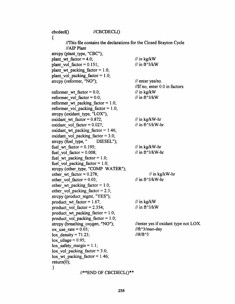
//This file contains the declarations//AIP Plant
strcpy (plant_type, "CBC");plant_wt_factor = 4.0;plant_vol_factor = 0.151;plant_wt_packingfactor = 1.0;plantvol_packing_factor = 1.0;strcpy (reformer, "NO");
reformer wtfactor = 0.0;reformer vol factor= 0.0;reformer_wtpacking_factor = 1.0;reformer_vol_packing_factor = 1.0;strcpy (oxidant_type, "LOX");
oxidant wt factor = 0.872;oxidant vol factor = 0.027;oxidant_wtpacking_factor = 1.46;oxidant_vol_packing_factor= 3.0;strcpy (fuel_type, " DIESEL");fuel wt factor = 0.195;fuel vol factor =0.008;fuel wtpackingfactor= 1.0;fuel_volpacking_factor = 1.0;strcpy (other_type, "COMP WATER");other wt factor = 0.278;other vol factor = 0.03;other_wtpacking_factor = 1.0;other_volpacking_factor = 2.3;strcpy (product_mgmt, "YES");product_wt_factor = 1.67;product_vol_factor = 2.354;product_wtpacking_factor = 1.0;product_vol_packing_factor = 1.0;strcpy (breathing_oxygen, "NO");ox use rate = 0.03;lox density = 71.23;lox_ullage = 0.95;lox_safety_margin = 1.1;lox_volpacking_factor = 3.0;lox_wtpackingfactor = 1.46;return(0);}
for the Closed Brayton Cycle
I in kg/kWI in ftA^3/kW
I enter yes/no.//If no, enter 0.0 in factorsI in kg/kW/ in ft^3/kW
// in kg/kW-hr// in ft^3/kW-hr
/ in kg/kW-hr// in ftA3/kW-hr
I in kg/kW-hr// in ftA3/kW-hr
I in kg/kWI in ftA3/kW
//enter yes if oxidant type not LOX.//ftA3/man-day//#/ft^3
//**END OF CBCDECLO**
238
cbcdeclo0 HCBCDECL(
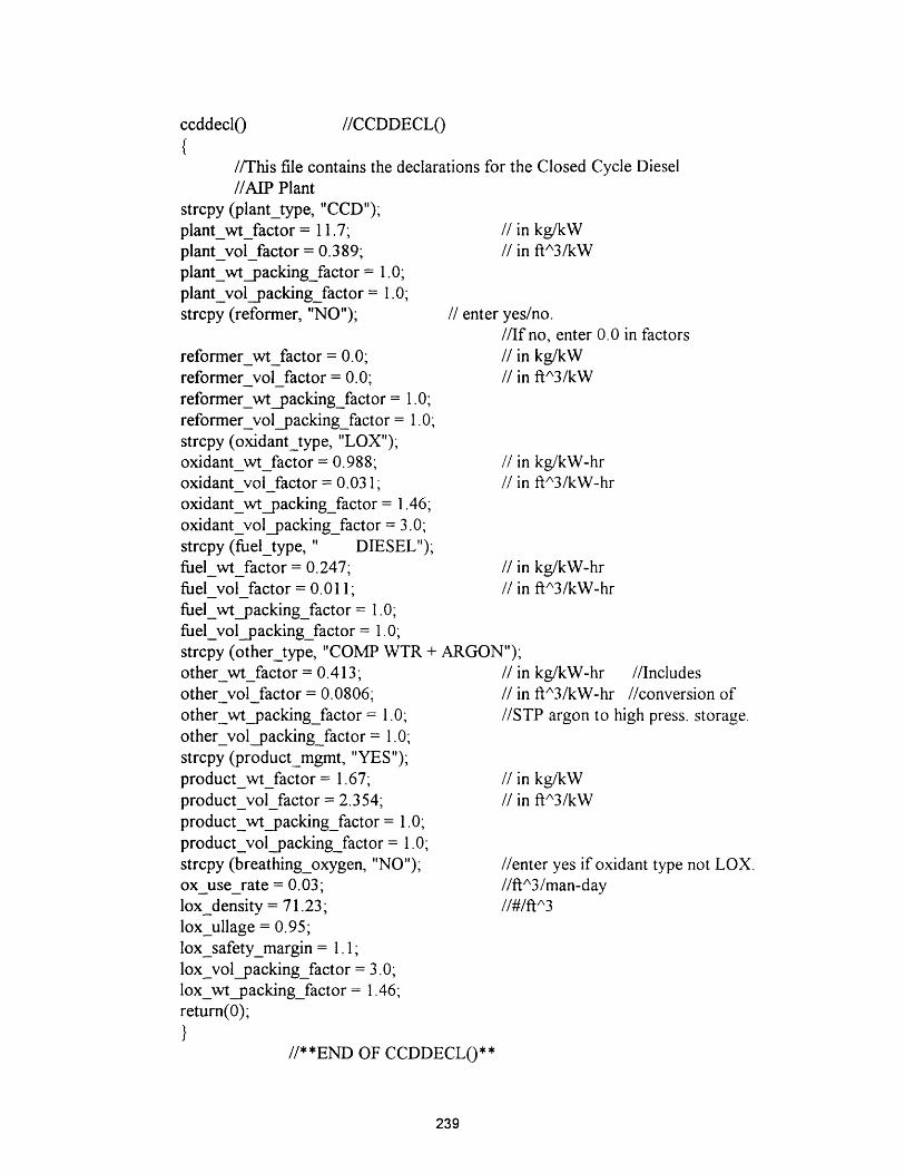
//This file contains the declarations for the Closed Cycle Diesel//AIP Plant
strcpy (plant_type, "CCD");plant_wtfactor = 11.7; // in kg/kWplant_vol_factor = 0.389; // in ftA3/kWplant_wtpacking_factor = 1.0;
plant_vol_packing_factor = 1.0;strcpy (reformer, "NO");
reformerwtfactor = 0.0;reformervolfactor = 0.0;reformer_wt_packing_factor = 1.0;reformer_vol_packing_factor = 1.0;strcpy (oxidant_type, "LOX");oxidant wt factor= 0.988;oxidant vol factor = 0.031;oxidant_wt_packing_factor = 1.46;oxidant_vol_packing_factor = 3.0;strcpy (fuel_type, " DIESEL");fuelwtfactor= 0.247;fuel vol factor = 0.011;fuel wtpackingfactor = 1.0;fuel_volpacking_factor = 1.0;strcpy (other-type, "COMP WTR +otherwtfactor = 0.413;othervol_factor = 0.0806;otherwtpacking_factor = 1.0;other_vol_packing factor = 1.0;strcpy (product_mgmt, "YES");product_wt_factor= 1.67;product_vol_factor = 2.354;product_wtpacking_factor = 1.0;product_vol_packing_factor = 1.0;strcpy (breathing_oxygen, "NO");ox_use_rate = 0.03;lox_density = 71.23;lox_ullage = 0.95;lox_safety_margin = 1.1;lox_volpacking_factor = 3.0;lox wtpacking factor = 1.46;return(0);}
/ enter yes/no.//If no, enter 0.0 in factorsI in kg/kW// in ft^3/kW
I in kg/kW-hr// in ft^3/kW-hr
I in kg/kW-hr// in ft^3/kW-hr
ARGON");I in kg/kW-hr //IncludesI in ftA3/kW-hr //conversion of//STP argon to high press. storage.
// in kg/kWI in ftA3/kW
//enter yes if oxidant type not LOX.//ftA3/man-day//#/ft^3
//**END OF CCDDECL(**
239
ccddecl() HCCDDECL(

{
//This file contains the declarations for the Molten Carbonate//FC AIP Plant
strcpy (plant_type, "MCFC");plant_wt_factor = 24.6; // in kg/kWplant_vol_factor = 1.08; // in ftA3/kW
plant_wt_packing_factor = 1.0;plantvol_packing_factor = 1.0;strcpy (reformer, "NO");
reformer wt factor = 0.0;reformer_vol_factor = 0.0;reformer_wtpacking_factor = 1.0;reformer_vol_packing_factor = 1.0;strcpy (oxidant_type, "LOX");oxidantwtfactor = 0.554;oxidant volfactor = 0.017;oxidant_wtpacking_factor = 1.46;oxidant_vol_packing_factor = 3.0;strcpy (fuel_type, " DIESEL");fuel wtfactor =0.165;fuelvolfactor= 0.007;fuel_wt_packingfactor= 1.0;fuel_volpacking_factor = 1.0;strcpy (other_type, "COMP WATER");otherwtfactor= 0.177;other vol factor = 0.0191;other_wtpacking_factor = 1.0;other_vol_packing_factor = 2.3;strcpy (productmgmt, "YES");product_wt_factor = 1.67;product_vol_factor = 2.354;product_wt_packing_factor = 1.0;product_vol_packing_factor = 1.0;strcpy (breathing_oxygen, "NO");oxuserate = 0.03;lox_density = 71.23;lox_ullage = 0.95;lox safety_margin = 1.1;lox_volpacking_factor = 3.0;lox_wt_packing_factor = 1.46;return(0);
}//**END OF MFCDECL0**
/ enter yes/no.//If no, enter 0.0 in factors
I in kg/kWI in ft^3/kW
//in kg/kW-hrI in ftA3/kW-hr
I in kg/kW-hrI in ftA3/kW-hr
I in kg/kW-hri in ftA3/kW-hr
// in kg/kW// in ftA3/kW
//enter yes if oxidant type not LOX.//ftA3/man-day//#/ftA3
240
mfcdeclo0 //MCFCDEC(
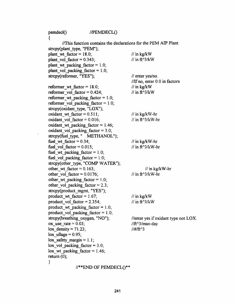
//This function contains the declarations for the PEM AIP Plantstrcpy(plant_type, "PEM");plant_wt_factor = 18.0; // in kg/kWplant_vol_factor = 0.343; // in ftA3/kWplant_wtpacking_factor = 1.0;plant_volpacking_factor = 1.0;strcpy(reformer, "YES");
reformer wtfactor = 18.0;reformervolfactor = 0.424;reformer_wt_packing_factor = 1.0;reformer_vol_packing_factor= 1.0;strcpy(oxidant_type, "LOX");oxidantwtfactor = 0.511;oxidant vol factor= 0.016;oxidant_wt packing_factor = 1.46;oxidant_vol_packing_factor = 3.0;strcpy(fuel_type, " METHANOL");fuelwtfactor= 0.34;fuelvolfactor = 0.015;fuel_wt_packing_factor = 1.0;fuel_vol packing_factor = 1.0;strcpy(other_type, "COMP WATER");otherwtfactor = 0.163;other_vol_factor = 0.0176;other_wtqacking_factor= 1.0;other_vol_packing_factor= 2.3;strcpy(product_mgmt, "YES");product_wt_factor= 1.67;product_vol_factor = 2.354;product_wtpacking_factor = 1.0;product_vol_packing_factor = 1.0;strcpy(breathing_oxygen, "NO");ox_userate = 0.03;lox_density = 71.23;lox_ullage = 0.95;loxsafety_margin = 1.1;lox_volpacking_factor = 3.0;lox_wt_packing_factor= 1.46;return (0);
}//**END OF PEMDECL0**
I enter yes/no.//If no, enter 0.0 in factorsI in kg/kW// in ftA3/kW
I in kg/kW-hr// in ftA3/kW-hr
// in kg/kW-hrI in ftA3/kW-hr
// in kg/kW-hrI in ftA3/kW-hr
I in kg/kWI in ftA3/kW
//enter yes if oxidant type not LOX.//ftA3/man-day//#/ftA^3
241
pemdeclO //PEMDECL(
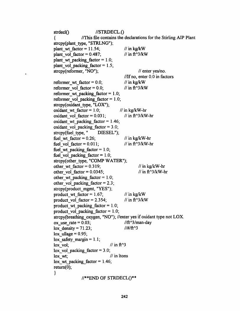
strdeclo //STRDECL.0{ //This file contains the declarations for the Stirling AIP Plantstrcpy(plant_type, "STRLNG");plant_wt_factor = 11.54; I in kg/kWplant_vol_factor = 0.487; // in ftA3/kWplant_wt_packing_factor= 1.0;plant_vol_packing_factor= 1.5;strcpy(reformer, "NO"); // enter yes/no.
//If no, enter 0.0 in factorsreformer_wt_factor = 0.0; //1 in kg/kWreformervolfactor = 0.0; // in ftA3/kWreformer_wtpacking_factor = 1.0;reformer_volpacking_factor = 1.0;strcpy(oxidant_type, "LOX");oxidant_wt_factor = 1.0; // in kg/kW-hroxidant vol factor = 0.031; // in ftA3/kW-hroxidant_wtpacking_factor = 1.46;oxidant_volpacking_factor = 3.0;strcpy(fuel_type, " DIESEL");fuel_wt_factor = 0.26; I in kg/kW-hrfuel volfactor = 0.011; I in ftA3/kW-hrfuel_wtpacking_factor= 1.0;fuel_vol _packingfactor= 1.0;strcpy(other_type, "COMP WATER");other_wt_factor = 0.319; // in kg/kW-hrothervolfactor = 0.0345; I in ftA3/kW-hr
other_wtpacking_factor = 1.0;other_vol_packing_factor = 2.3;strcpy(product_mgmt, "YES");product_wt_factor = 1.67; // in kg/kWproduct_vol_factor = 2.354; I in ftA3/kW
product_wt_packing_factor= 1.0;product_vol_packing_factor= 1.0;strcpy(breathing_oxygen, "NO"); //enter yes if oxidant type not LOX.oxuserate = 0.03; //ft^3/man-daylox density = 71.23; //#/ftA3
lox_ullage = 0.95;lox safety_margin = 1.1;lox_vol; // in ft^3
lox_vol_packing_factor = 3.0;lox_wt; //in ltonslox_wt_packingfactor = 1.46;return(0);
}//**END OF STRDECL(**
242

1.6 SAMPLE OUTPUT
****AIP SIZING PROGRAM OUTPUT****
INPUT DATA PEM
Range: Total Ship Range (nm)Snort @ 10 kts (nm)Submerged @ 8 kts AIP (days)Submerged creep @ 4 kts on battery (hours)Submerged burst @ 20 kts on battery (hours)Submerged transit @ 13 kts on battery (hours)Recharge time @ 4 kts (hours)SOA (kts) 10.04 Indescretion Ratio
10000520025902.9414.25.30.26
Diving Depth (ft):Torpedo Tubes:Mission Length (days):.
9004
Crew Size:Reloads:60
4421
MARGINS
Fixed Ballast (% NSC):Outboard Items I( VDh):Freeflood Volume (% Veb):
0.112 Variable Load (% NSC:0.18 Res. Buovancy (% Veb!:0.06
ENVELOPE
Length (ft):Cpf: 0.75
202.35Cpa:
Diameter (ft):0.6429 Cwsf: 0.8452
VOLUMES (ft^3)
Weapons:Ship Support:Pressure Hull:Everbuoyant:Submerged:Envelope:
6785.7113923.3676070.2 Outboarc89762.84103227.27108613.04
Mobility:C^3I:i: 13692.64Main Ballast Tanks:Freeflood:
WEIGHTS (ltons)
Structure:Weapons:Ship Support:#Variable Load:
771.5642.57103.76128.22
Mobility:C^3I:Fixed Ballast:Normal Surf. Condition:
MOBILITY
Battery Type: Lead AcidBattery: Weight(ltonJ: 497.79Capacity(kW-hr 2hr rate):Propulsive Coeff: 0.86Hotel Load (kW): 138.96
Number of BatteriesVolumeift^3):10424.87Installed SHP:#Bunker Fuel (ltons):
AIP
AIP Plant Size (kW):Type: PEMReformer: YESOxidant: LOXBreath: LOX: NOFuel: METHANOLOther: COMP WATERCosworth: YES
353.45Weight(ltons):Weight(ltons):#Weight(ltons):#Weight(ltons):#Weiht(ltons):#Weight[ltons):Weight(ltons):
6.266.26155.754.2670.9834.030.58
Volume(ft^3):121.23Volume(ft^3):149.86Volume(ft^3):10179.47Volume(ft^3):275.12Volume(ft^3):3181.09Volume(ft-3):8584.69Volume(ft'3):832.03
Weight(ltons): 278.12 Volume(ft^3):23323.5
243
0.050.15
31Cwsa:
L/D:0.75
6.53
50061.135300
13464.435385.77
1167.9664.11286.182564.36
6.525212.43
3920.66140.18
Totals:

(Reverse Blank)
i i
244