biomass nextgen - newhorizoncorp.comnewhorizoncorp.com/pdf/biomass11v2.pdf · the purpose of this...
TRANSCRIPT
-1-
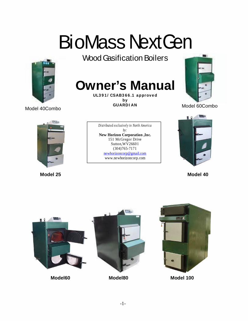
BioMass NextGen Wood Gasification Boilers
Model 40Combo
Owner’s Manual UL391/CSAB366.1 approved
by GUARDIAN
Model 60Combo
Distribut ed exclusivel y in North America by:
New Horizon Corporation ,Inc. 151 McGregor Drive
Sutton,WV26601 (304)765-7171
[email protected] www.newhorizoncorp.com
Model 25 Model 40
Model60 Model80 Model 100

-2-
-3
Table of Contents
General Information...................................................4
Fuel sources..............................................................5
Boiler construction and design...................................5
How the boiler works..................................................5
Technical information and data...................................6
Specifications diagram................................................6
Technical information and specifications....................7
RK2001UA-D controller operation..............................8
Air Adjustment Examples...................................8
Boiler operation..........................................................9
Starting the fire...........................................................9
Loading fuel................................................................9
Maintaining and cleaning the boiler............................9
Additional maintenance tips.......................................10
Boiler assembly and installation.................................10
Hot water storage tank..............................................11
BioMass Combo Notes......................................12
Recommended clearances........................................14
Boiler parts and features..........................................15
Open system setup...................................................17
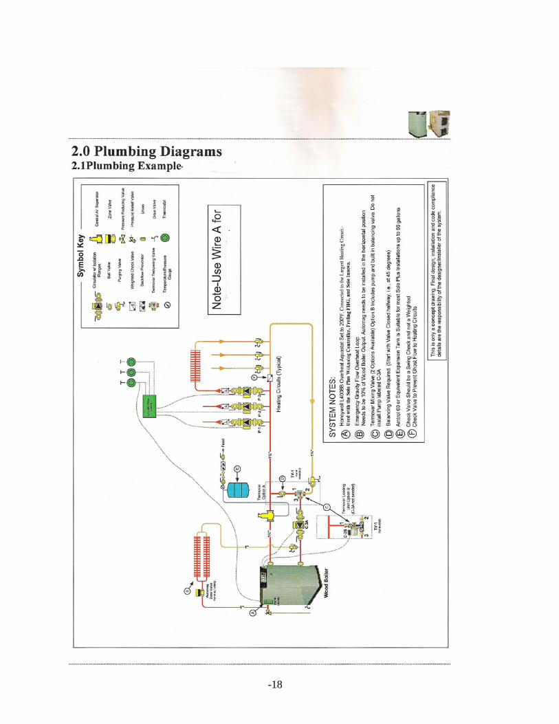
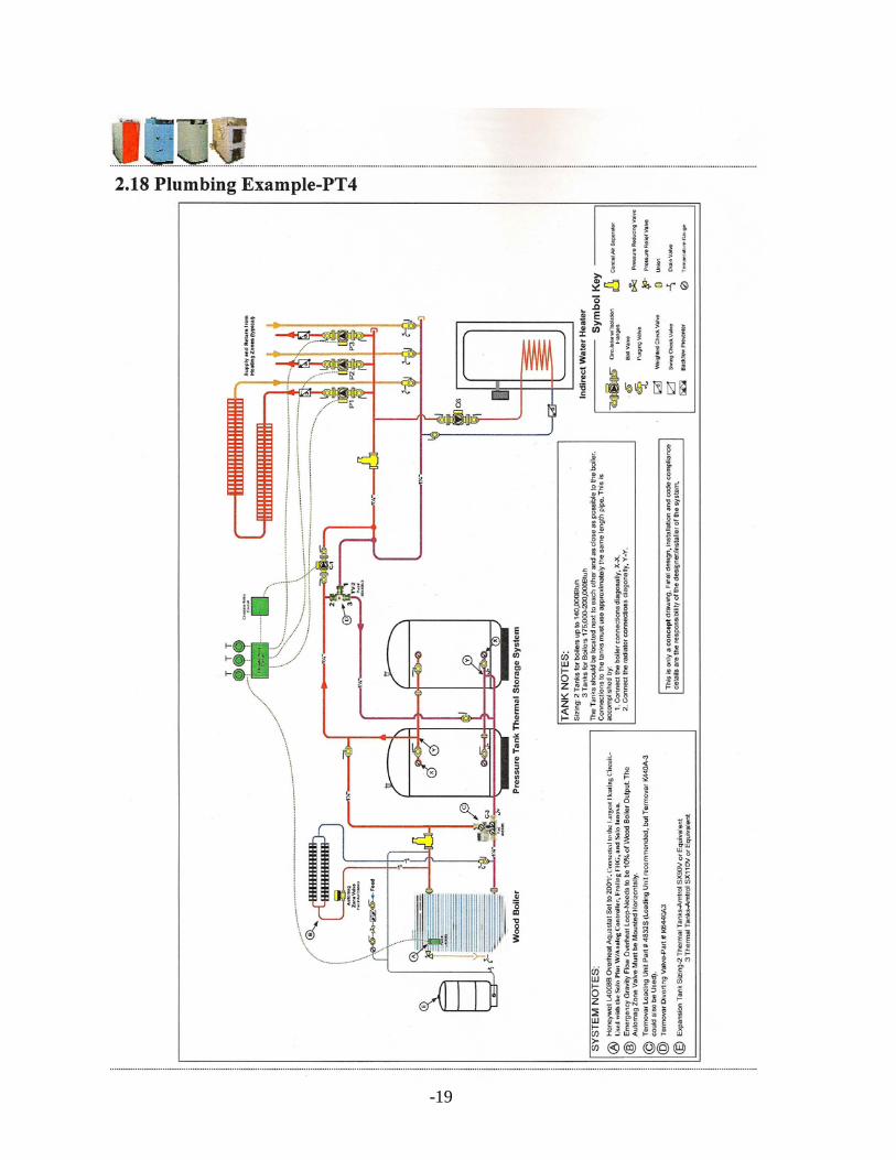
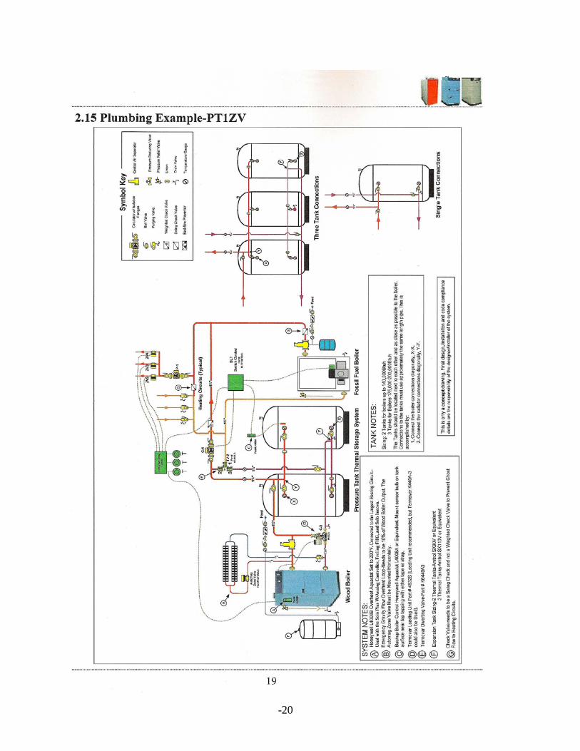
Plumbing Diagram Examples.....................................18
Electrical setup for Model 40....................................21
Electrical setup for Model 60....................................22
Manufactured for New Horizon Inc. by: "HAMECH"-POLAND 17-200HAJNÓWKA
ul.ArmiiKrajowej3 tel. 856822021do26 fax
856822207

-4
General Information Problems associated with excessive wood smoke, high wood usage and frequent tending and maintenance are all addressed and solved with the BioMass NextGen gasification boiler line. Wood gasification is the proven clean, efficient and environmentally responsible way to burn wood in the 21st Century.
The purpose of this manual is to explain how the BioMass NextGen gasification boiler operates and how it works within the hydronic central heating system. We highly recommend that every new owner read this manual completely before operating the boiler. Failure to install or operate the boiler as described in this manual will void the warranty. BioMass boilers should be installed by a certified plumber or plumbing and heating contractor or technician. New Horizon Inc. does not take any responsibility for incorrect installation or improper boiler usage.
BioMass boilers are generally used for heating homes and small commercial buildings. The water temperature inside the boiler cannot exceed 200°F. The display on the boiler’s controller will show the current operating temperature in Fahrenheit.
NOTE: The BioMass boiler was designed to operate in both closed and open heating systems.
Please refer to the table below to determine the suitable BioMass boiler model for the space you are trying to heat.
Disclaimer: New Horizon is not responsible for incorrect sizing o f boiler.
BioMass Btu Output Heated Area Boiler Model (per hour) (square feet) BM25 85KBtu 2200 BM40 137KBtu 3500 BM60 205KBtu 6000 BM80 275KBtu 8500 BM100 343KBtu 11000
-5
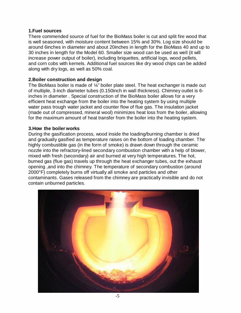
1.Fuel sources There commended source of fuel for the BioMass boiler is cut and split fire wood that is well seasoned, with moisture content between 15% and 30%. Log size should be around 6inches in diameter and about 20inches in length for the BioMass 40 and up to 30 inches in length for the Model 60. Smaller size wood can be used as well (it will increase power output of boiler), including briquettes, artificial logs, wood pellets, and corn cobs with kernels. Additional fuel sources like dry wood chips can be added along with dry logs, as well as 50% coal.
2.Boiler construction and design The BioMass boiler is made of ¼” boiler plate steel. The heat exchanger is made out of multiple, 3-inch diameter tubes (0.150inch in wall thickness). Chimney outlet is 6-inches in diameter . Special construction of the BioMass boiler allows for a very efficient heat exchange from the boiler into the heating system by using multiple water pass trough water jacket and counter flow of flue gas. The insulation jacket (made out of compressed, mineral wool) minimizes heat loss from the boiler, allowing for the maximum amount of heat transfer from the boiler into the heating system.
3.How the boiler works During the gasification process, wood inside the loading/burning chamber is dried and gradually gasified as temperature raises on the bottom of loading chamber. The highly combustible gas (in the form of smoke) is drawn down through the ceramic nozzle into the refractory-lined secondary combustion chamber with a help of blower, mixed with fresh (secondary) air and burned at very high temperatures. The hot, burned gas (flue gas) travels up through the heat exchanger tubes, out the exhaust opening ,and into the chimney. The temperature of secondary combustion (around 2000°F) completely burns off virtually all smoke and particles and other contaminants. Gases released from the chimney are practically invisible and do not contain unburned particles.

-6
For ease of operation, the BioMass is equipped with an RK2001UA-D controller, which is located on the top of the boiler and clearly visible and accessible from the front of the boiler.
Function of the Controller:
1.Reach operation temperature (pre-set on dial) by operating variable
speed blower 2.Operate water circulating pump in preprogrammed setting 3.React with room thermostat (advance setting) 4.For Combo Units: During wood burning, oil/gas burner is disabled, usingaUM-1 relay (optional). After wood burns out, UM-1relay will close contacts and enable oil/gas burner to operate.
In case of excessive water temperature (creepingover195°F during IDLE), overheating should be prevented by a strap-on aquastat, which should activate dump zone (in garage or in basement to relieve excess heat). Controller is also able to automatically shut down operation of blower in a case of system failure (will leave pump operating).
BioMass Boiler Dimensions See page 7 for details.
1.Hot water supply 2.Cool water return 3.Drain valves
-7
Technical Info Models
BioMass 25 40 60 80 100 Rated Power Output BTU 140 205 275 342 European standard EN 303-5
Yes Yes Yes Yes Yes
Fuel Moisture Level CordofWood–withamaximumof30%moisture Power Range BTU 40-85KBTU 50K–145K
BTU 60K–215K
BTU 120K–
300KBTU 200K-390K
Efficiency % 91.2 91 91 91 90 Possible Fuels Seasoned Wood, Briquettes ,Corn Cobs with
Kernels, Temperature Adjustment
Range °F 150-195F 150-195F 150-195F 150-195F 150-195F
Total Weight Lb 1190 1480 1780 2100 3580 Height with Controller Housing
Ain 59 59 59 63 80
Height of Hot Water Outlet
Bin 56 56 59 62.5 80
Height of Return Water Pipe
Cin 32 32.6 32.4 36.5 5.5
Height of Water Drain Valve
Din 2.7 2.7 2.7 2.75 5.5
Height of Flue Pipe Ein 46.5 46.5 46.5 49.5 70 Width with Clean-up Lever
Fin 25 31.5 31.5 31.5 33.2
Depth Hin 39 39 54.5 59.0 78.7 Distance of Hot Water Outlet
Iin 9.5 9.5 9.5 14.0 60.4
Flue Pipe Size Jin 6” 6” 6” 8” 8 Hot Water Outlet Pipe Size
Gin 2” 2” 2” 2” 2”
Water Return Pipe Size Gin 2” 2” 2” 2” 2” Drain Pipe Size G ¾” 3/4´´ 3/4´́ 3/4” ¾” Boiler Water Capacity gal 33 40 50 68 110 Flue Temperature -Max power output °F 320 330 330 310 295 -Min power output °F 195 210 210 210 200 Size of Loading Chamber
-depth in 19” 20.5 30.3 30.75 45 -height in 28” 24.8 24.8 34.0 39 -width in 18.5” 24.8 24.8 24.75 26 Volume of Loading Chamber
gal 40 60 75 140
Noise Level dB 30 31 31 31 31 Power Consumption W 80W(1.4A) 80(1.4A) 140(2.2A) 140(2.2A) 140(2.4A) Voltage/Frequency V/Hz 120V/60Hz 120V/60 120V/60 120V/60 120V/60HZ

-8
RK2001UA-D controller operation Before connecting the RK2001UA-D regulator to an electrical circuit, always follow these safety precautions:
• Make sure that all the safety covers are in their appropriate place; • Make sure that the electrical wires do not come in contact with any hot part
of the boiler and the length of the wires used is sufficient; • Confirm that the electrical outlet and the controller have the same voltage(110
V).
When these precautions have been taken, plug the regulator into the electrical outlet (110V )and then turn on the power switch. The regulator will automatically reset itself and display the current boiler temperature. The regulator should not be exposed to extreme sunlight or heat. If dust or dirt should accumulate on top of the regulator cover, the regulator can be cleaned gently with a soft cloth.
*Air Adjustment* (examples of proper air adjustment)
Primary air
On BioMass 60,80&100
Secondary air
On BioMass 25&40
-9
4.Boiler operation Before firing the boiler up for the first time:
• Please read the entire owner’s manual; • Confirm that your entire hydronic heating system has enough water; • Confirm that the boiler is connected to the correct power source; • Confirm that the water pump is primed, fully operational and
connected to the regulator; • Confirm that the removable fireproof bricks in the bottom chamber are
properly positioned underneath the nozzle and in front of the bottom door. 5.Starting the fire When starting the fire:
• Open the top (loading) door and fill the bottom layer of the loading
chamber with easily flammable material like paper and kindling; • Add some dry fire wood; • Keep the chimney flap open( or ,if you prefer ,closed for down draft); • Set fire to the paper; • DO NOT LEAVE THE BOILER UNATTENDED DURING THIS STAGE!!! • After about 15 to 20 minutes, the fire wood should be burning; • Carefully open the upper door (open bypass flap to prevent escape of smoke)
and fill the entire loading chamber with fuel (make sure that the draft blower is operating to prevent smoke from escaping)
• Close the upper door tightly and close bypass flap • Set the desired water temperature on the controller
6.Reloading fuel procedure
• Before opening loading door, open bypass flap (crack open door and allow venting. Wait 10–15 seconds).
• Fill up the upper loading chamber with dry firewood; • Close the upper door tightly and shut bypass flap by pulling lever.
CAUTION!
When boiler is operating, bypass flap must be closed. 7.Maintaining and cleaning the boiler For the boiler to operate most efficiently, it is vital that it be cleaned frequently. This includes removing ash as needed, as well as cleaning the heat exchanger tubes everyday by moving lever on side of boiler. When using fuel with higher moisture content, excessive creosote can buildup in the burning chamber.
To keep creosote formation to a minimum, burn seasoned dry wood. When the heat exchanger tubes are cleaned by moving the lever(19), some fly ash will deposit at the bottom of the heat exchanger tubes. To remove the ash from the bottom section of the
-10
heat exchange run screw the access side panel(23) on the side of the boiler, and access panel(22); remove the ash by sweeping it away and close up the panels periodically.
Removing ash from the gasification chamber(bottom) normally should be done once every 7-10 days, depending on the moisture content of the wood and amount of wood burned. High moisture in wood will cause more ash and creosote buildup, drop in overall efficiency, increase wood consumption, and over time will shorten the life of the boiler.
WARNING!
When cleaning out the ash from the bottom chamber, wear heat resistant gloves. Ceramic pieces are VERY HOT and should never be touched directly when the boiler has recently been used.
Make sure to clean the air inlets periodically by removing the blower cover(7) and air access covers, which will make the air intake tubes accessible. There might be some creosote present. Use a metal scraper or small gas torch to burn off and assure that air can freely flow.
WARNING!
When shutting down the boiler at the end of the heating season, thoroughly clean both chambers. It is a good idea to burn some wood from time to time to keep boiler dry inside to increase the longevity of the unit.
8.Additional maintenance tips During the heating season, regularly check:
• water pressure in your heating system • leaks in your heating system • heat exchanger seal • door seals
9.Boiler assembly and installation BioMass Boilers are delivered fully assembled. It is the purchaser’s responsibility to check that the boiler was delivered undamaged and fully equipped. It is essential that the boiler be installed on a hard surface with enough room all around to allow for easy access, cleaning and maintenance. To connect the boiler to the chimney, use a 6-inchdiameter chimney pipe. The chimney pipe should be pitched slightly upwards and the connection with the boiler should be carefully insulated with hi-temp silicone to prevent smoke leakage. The diameter of the chimney should not be smaller than 6 inches, and not lower than 12 feet in height from the base. BioMass boilers can be located in an outdoor building, such as a shed or a garage, or in a well ventilated basement with a constant air supply from outside.
-11
IMPORTANT! The BioMass boiler should be installed by a licensed or certified heating professional. The BioMass boiler should have a backup power system to prevent overheating in the event of a power outage. The simplest arrangement consists of an inverter (350W computer power backup) and a marine battery connected to the inverter to increase operating time.
A properly installed heating system should include a 3-way mixing valve to prevent low returning water temperature, which can cause thermal shock. Preventing thermal shock increases the life span of the boiler.
The water pump, or circulator, should be directly connected to the controller, which will facilitate smooth operation of the boiler and heating system and should not operate below 140F to prevent condensation inside burning chamber.
10.Hot water storage tank The use of a hot water storage tank with the BioMass boiler is highly recommended, but not necessary. Depending on the size of the space being heated, the storage tank should be between 500 and 1,000gallons. Storage tanks:
• Decrease fuel consumption • Increase the life span of the boiler by decreasing idle time during the
outside temperature changes • Make the entire heating system more efficient and easier to operate • Decrease pollution
WARNING! Final installation should conform to all local codes and other regulations.
When using “PEX” tubing, make sure it is adapted for pressurized, closed systems. It should contain an oxygen barrier. Piping to and from the boiler should consist of at least one-inch diameter copper or PEX.
For SAFETY reasons, make sure that the heating system and the boiler have pressure relief valves and expansion tanks installed in the appropriate places. Check local codes.
WARNING!
Always use SAFETY precautions when conducting any kind of maintenance or repair on the boiler. Repairs should be made by a licensed or certified heating contractor.
-12
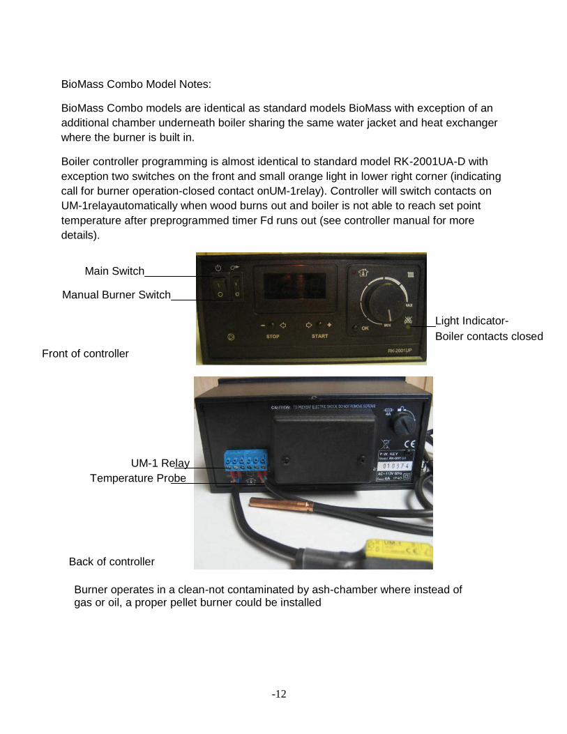
BioMass Combo Model Notes:
BioMass Combo models are identical as standard models BioMass with exception of an additional chamber underneath boiler sharing the same water jacket and heat exchanger where the burner is built in.
Boiler controller programming is almost identical to standard model RK-2001UA-D with exception two switches on the front and small orange light in lower right corner (indicating call for burner operation-closed contact onUM-1relay). Controller will switch contacts on UM-1relayautomatically when wood burns out and boiler is not able to reach set point temperature after preprogrammed timer Fd runs out (see controller manual for more details).
Main Switch
Manual Burner Switch Front of controller
Light Indicator- Boiler contacts closed
UM-1 Relay Temperature Probe
Back of controller
Burner operates in a clean-not contaminated by ash-chamber where instead of gas or oil, a proper pellet burner could be installed
-13
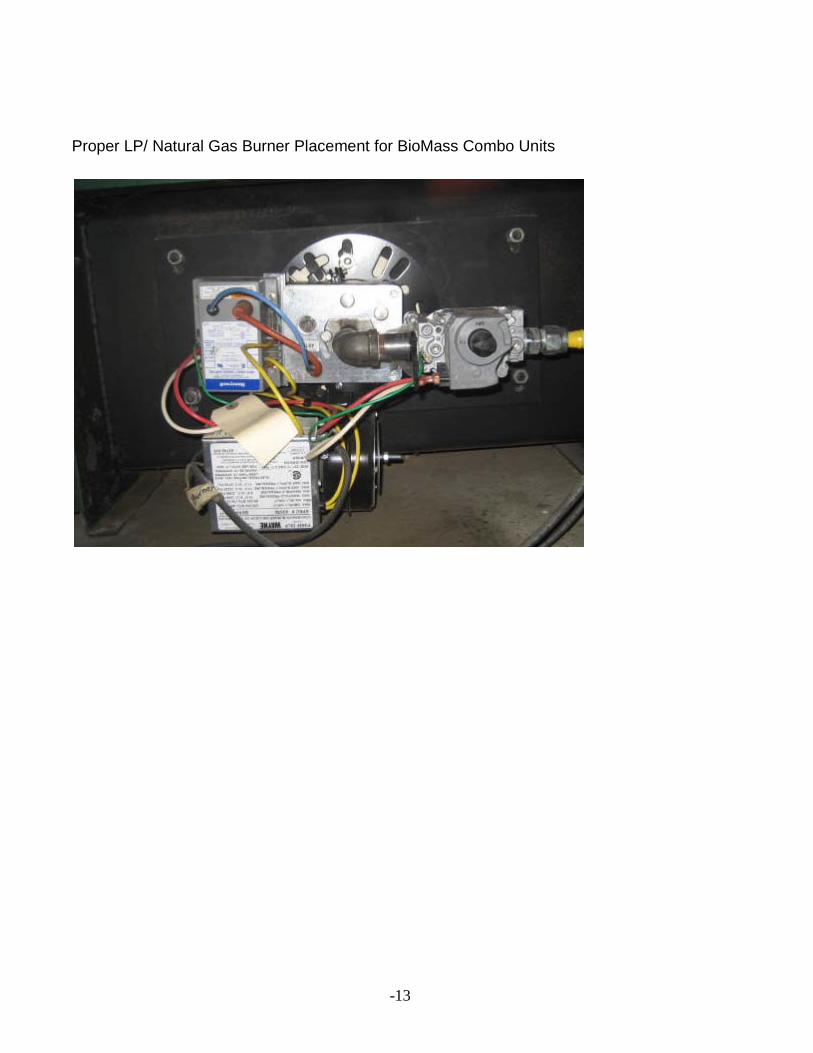
Proper LP/ Natural Gas Burner Placement for BioMass Combo Units
-14
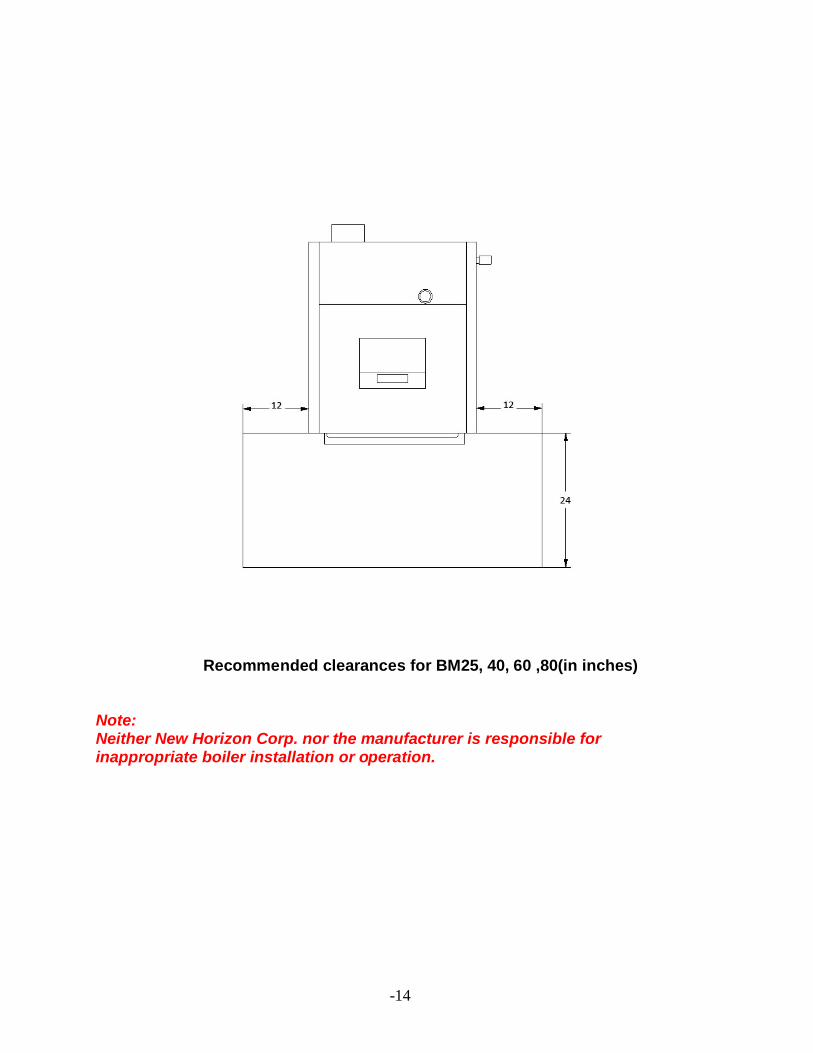
Recommended clearances for BM25, 40, 60 ,80(in inches) Note: Neither New Horizon Corp. nor the manufacturer is responsible for inappropriate boiler installation or operation.
-15
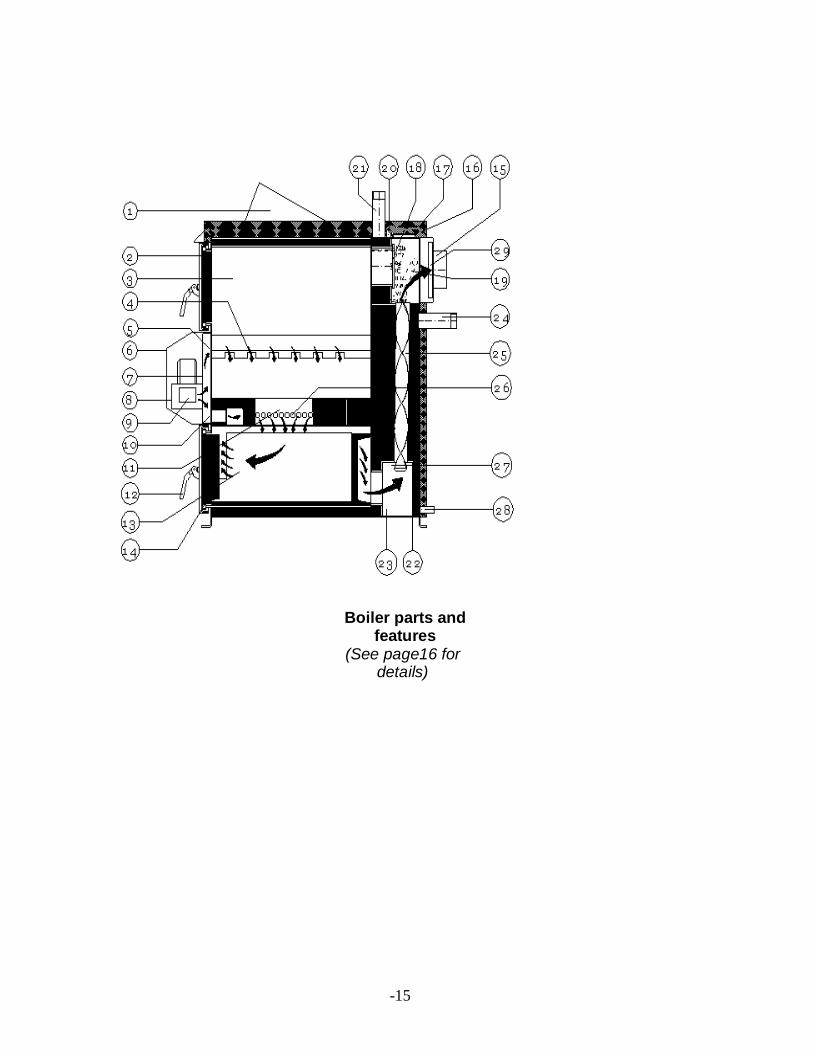
Boiler parts and features
(See page16 for details)
-16
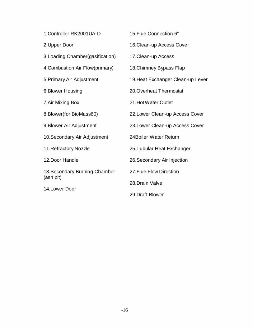
1.Controller RK2001UA-D
2.Upper Door
3.Loading Chamber(gasification)
4.Combustion Air Flow(primary)
5.Primary Air Adjustment
6.Blower Housing
7.Air Mixing Box
8.Blower(for BioMass60)
9.Blower Air Adjustment
10.Secondary Air Adjustment
11.Refractory Nozzle
12.Door Handle
13.Secondary Burning Chamber (ash pit)
14.Lower Door
15.Flue Connection 6” 16.Clean-up Access Cover 17.Clean-up Access 18.Chimney Bypass Flap 19.Heat Exchanger Clean-up Lever 20.Overheat Thermostat 21.Hot Water Outlet 22.Lower Clean-up Access Cover 23.Lower Clean-up Access Cover 24Boiler Water Return 25.Tubular Heat Exchanger 26.Secondary Air Injection 27.Flue Flow Direction 28.Drain Valve 29.Draft Blower
-17
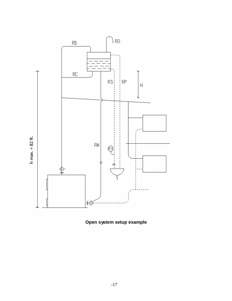
Open system setup example
-18
-19
-20
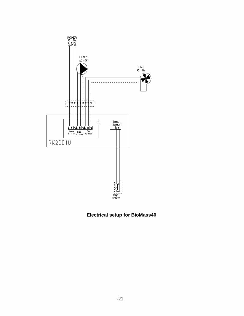
-21
Electrical setup for BioMass40
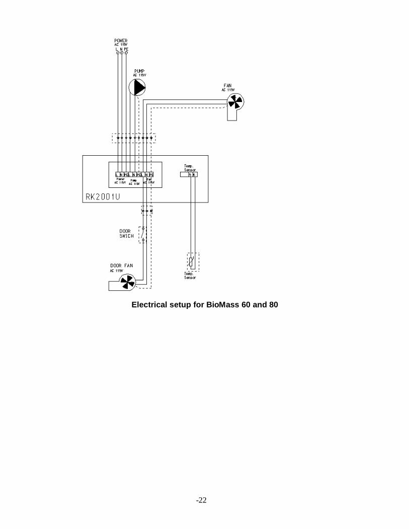
-22
Electrical setup for BioMass 60 and 80
-23
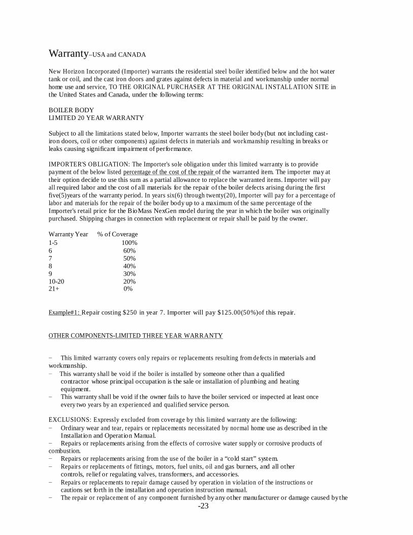
Warranty Year % of Coverage 1-5 100% 6 60% 7 50% 8 40% 9 30% 10-20 20%
Warranty–USA and CANADA
New Horizon Incorporated (Importer) warrants the residential steel boiler identified below and the hot water tank or coil, and the cast iron doors and grates against defects in material and workmanship under normal home use and service, TO THE ORIGINAL PURCHASER AT THE ORIGINAL INSTALLATION SITE in the United States and Canada, under the following terms:
BOILER BODY LIMITED 20 YEAR WARRANTY
Subject to all the limitations stated below, Importer warrants the steel boiler body (but not including cast-iron doors, coil or other components) against defects in materials and workmanship resulting in breaks or leaks causing significant impairment of performance.
IMPORTER'S OBLIGATION: The Importer's sole obligation under this limited warranty is to provide payment of the below listed percentage of the cost of the repair of the warranted item. The importer may at their option decide to use this sum as a partial allowance to replace the warranted items. Importer will pay all required labor and the cost of all materials for the repair of the boiler defects arising during the first five(5)years of the warranty period. In years six(6) through twenty(20), Importer will pay for a percentage of labor and materials for the repair of the boiler body up to a maximum of the same percentage of the Importer's retail price for the BioMass NexGen model during the year in which the boiler was originally purchased. Shipping charges in connection with replacement or repair shall be paid by the owner.
21+ 0%
Example#1: Repair costing $250 in year 7. Importer will pay $125.00(50%)of this repair.
OTHER COMPONENTS-LIMITED THREE YEAR WARRANTY
− This limited warranty covers only repairs or replacements resulting from defects in materials and workmanship. − This warranty shall be void if the boiler is installed by someone other than a qualified
contractor whose principal occupation is the sale or installation of plumbing and heating equipment.
− This warranty shall be void if the owner fails to have the boiler serviced or inspected at least once every two years by an experienced and qualified service person.
EXCLUSIONS: Expressly excluded from coverage by this limited warranty are the following: − Ordinary wear and tear, repairs or replacements necessitated by normal home use as described in the
Installation and Operation Manual. − Repairs or replacements arising from the effects of corrosive water supply or corrosive products of combustion. − Repairs or replacements arising from the use of the boiler in a “cold start” system. − Repairs or replacements of fittings, motors, fuel units, oil and gas burners, and all other
controls, relief or regulating valves, transformers, and accessories. − Repairs or replacements to repair damage caused by operation in violation of the instructions or
cautions set forth in the installation and operation instruction manual. − The repair or replacement of any component furnished by any other manufacturer or damage caused by the
-24
functioning or malfunctioning of any such component. − Repairs or replacements caused by thermal shock.
PURCHASER'S LEGAL RIGHTS: This warranty gives you specific legal rights, and you may also have other rights which may vary from state to state. This warranty shall not be construed as inconsistent with any federal, state or municipal law or any regulations promulgated in connection herewith. Questions regarding this warranty may be referred to: New Horizon Corporation, Inc. 151 McGregor Drive Sutton, WV 26601 (304)765-7171, [email protected]
HOW AND WHERE TO GET SERVICE. Repairs or replacements under this limited warranty must be performed by your dealer or someone authorized by him. You may be required to present this limited warranty to the dealer before any work is performed. You must pay for any work performed which is not covered by this limited warranty or which is not authorized by the dealer.
Disposal and recycling of boiler components BioMass NexGen boilers contain steel, electronic components, insulation and other materials that may be subject to local, state or federal regulations as to their proper disposal. When retiring a BioMass NexGen boiler from service, make sure that all applicable laws, rules and regulations are observed. When in doubt, check with your local regulating authority for scrapping and disposal guidelines.
Distributed in North America by: New Horizon Corporation, Inc. 151 McGregor Drive Sutton, WV 26601 (304)765-7171 [email protected]