biological contents considerations of maxillary …
TRANSCRIPT
.
1
BIOLOGICAL CONSIDERATIONS OF
MAXILLARY EDENTULOUS ARCH
Dr GYAN PRAKASH
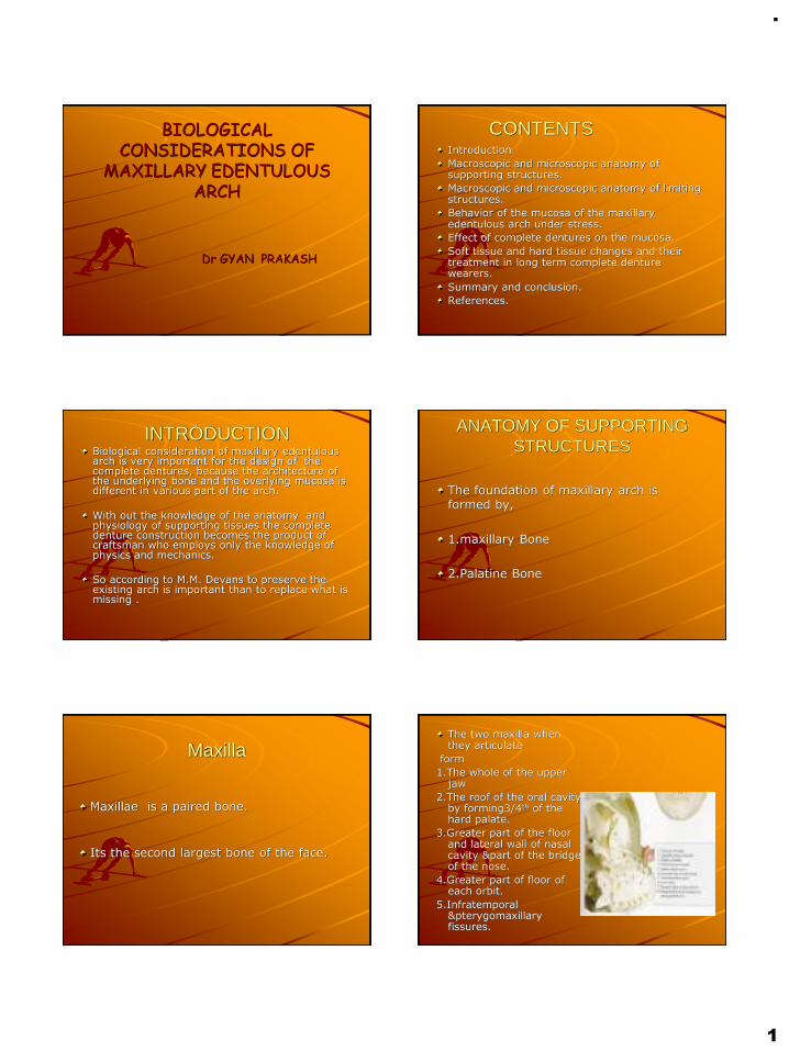
CONTENTSIntroduction
Macroscopic and microscopic anatomy of supporting structures.
Macroscopic and microscopic anatomy of limiting structures.
Behavior of the mucosa of the maxillary edentulous arch under stress.
Effect of complete dentures on the mucosa.
Soft tissue and hard tissue changes and their treatment in long term complete denture wearers.
Summary and conclusion.
References.
INTRODUCTIONBiological consideration of maxillary edentulous arch is very important for the design of the complete dentures, because the architecture of the underlying bone and the overlying mucosa is different in various part of the arch.
With out the knowledge of the anatomy and physiology of supporting tissues the complete denture construction becomes the product of craftsman who employs only the knowledge of physics and mechanics.
So according to M.M. Devans to preserve the existing arch is important than to replace what is missing .
ANATOMY OF SUPPORTING STRUCTURES
The foundation of maxillary arch is formed by,
1.maxillary Bone
2.Palatine Bone
Maxilla
Maxillae is a paired bone.
Its the second largest bone of the face.
The two maxilla when they articulate
form
1.The whole of the upper jaw
2.The roof of the oral cavity by forming3/4th of the hard palate.
3.Greater part of the floor and lateral wall of nasal cavity &part of the bridge of the nose.
4.Greater part of floor of each orbit.
5.Infratemporal &pterygomaxillary fissures.
.
2
Parts of the maxilla
1.Body.
2. Four processes-
– Frontal
– Zygomatic
– Alveolar
– Palatine
BODY –encloses a maxillary sinus
Has 4 surfaces
1 Anterior(facial or malar)
2.Posteror(infratemporal surface)
3. superior(orbital)
4. medial(nasal)
Anterior surface-faces forward &laterally.
. Consists of-1. incisive fossa
2.cannine fossa
3.cannine eminenence.
4.infraorbital foramen.
5. levator labii superioris muscle
6. nasal notch
7. anterior nasal spine.
Posterior(infratemporal) surface:convex, faces backward & laterally. Forms the anterior wall of infratemporal fossa.
Consists of –foramen of alveolar canals
. Maxillary tuberosity
Superior(orbital surface):smooth, roughly triangular and slightly concave;forms the greater part of the floor of the orbit.
Medial(nasal)surface:forms greater part of lateral wall of nasal cavity.
Processes
1. frontal process:
projects upwards from the body & is situated between the nasal bone in front and the lacrimal bone behind.
2.zygomatic process:
projects upward and laterally from the body
It forms the anterior part of zygomatic arch.
Its posterior surface is smooth and concave and forms part of anterior boundary of the infratemporal fossa

.
3
- PALATAL PROCESS:extends horizontally from the medial surface of the maxillae where the body meets the alveolar process.
Consists of 2 surfaces-inferior,superior
- 3 borders –medial,posterior, laterial.
1.Superior surface:nasal crest.
2. inferior surface:greater palatine groove
:incisive fossa
:incisive canal
:anterior & posterior incisive foramina
:incisive suture.
Borders:1. medial border- rough, articulates with the corresponding border of opposite site.
.nasal crest
.incisor crest.
.anterior nasal spine.
Posterior border: articulates with anterior border of horizontal plates of palatine bone.
Lateral border:fused with lower part of nasal surface of the body.
Alveolar process:
Extends inferiorly from the body of maxilla & supports the teeth with bony sockets.
When the teeth are extracted, alveolus left is called residual alveolar ridge.
PALATINE BONE
The two palatine bones lie together at the posterior part of nasal cavity between the maxillae& the pterygoid process of sphenoid bone.Resembles the letter ‘L‘ in shape.
Parts-1. two plates.
.horizontal
.perpendicular2.three process
.pyramidal
.orbital
.sphenoidal.
HARD PALATEThe foundation for the maxillary denture is formed by the hard palate & alveolar ridges.
The hard palate is formed by:
palatine process of maxillary bone & horizontal plate of palatine bones.
-cross shaped set of sutures transverse the palate.
MID PALATINE RAPHEThe palatine process of the maxillae are joined at the midline in the median suture extends from incisive papilla to the posterior region of hard palate.
The center of the palate is very hard because the layer of soft tissue covering the bone in this region is very thin.
Should be relieved ,otherwise results in –.rocking of the denture
.denture soreness.
.
4
Microscopic features of the palate.Epithelium is stratified squamous epithelium,well keratinized.Varies considerably in consistency and thickness in different locations.Zones recognized are:Anterolateral area:fatty zonePosterolateral area: glandular zone.Mid palatine raphe:median area.
:submucosa is
extremely thin
;nonresilient.
Anterolateral part Posterolateral part
Midpalatine
These tissues should be recorded in a resting condition because when they are displaced in the final impression, they tend to return to the normal form within the complete denture base, creating an unseating force on the denture or soreness in the patients mouth.
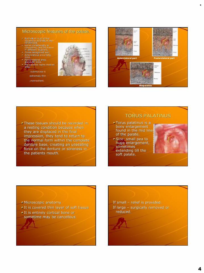
TORUS PALATINUSTorus palatinus is a bony enlargement found in the mid line of the palate.
Size- small pea to huge enlargement, sometimes extending till the soft palate.
Microscopic anatomy
It is covered thin layer of soft tissue
It is entirely cortical bone or sometime may be cancellous
If small – relief is provided.
If large – surgically removed or reduced.
.
5
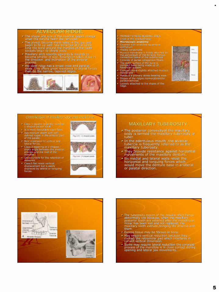
ALVEOLAR RIDGE.The shape and size of the alveolar ridges change when the natural teeth are removed.The alveoli become mere holes in the jaw and begin to fill up with new bone but at the same time the bone around the margins of the tooth sockets begin to shrink awayMaxillary arch resorbs upwards & inwards to become smaller in size. Resorption takes place in the direction and inclination of the alveolar process.the ideal ridge has a broad crest and parallel sides. This offers great resistance to lateral forces than do the narrow, tapered ridges.
PRIMARY STRESS BEARING AREA.Crest of the residual ridge.Microscopic anatomy:Covered with stratified squamous epitheliumThickly keratinizedMucous membrane is firmly attached to the periosteum of the bone by fibrous connective tissue of the submucosa.Consists of dense collagenous fibers.The outer surface of the bone is compact bone being made up of haversian system.Compact bone+tightly attached mucous membraneMakes it a primary stress bearing area.Slopes of the ridges:nonkeratinizedor parakeratinized.Loosely attached to the slopes of the ridge.
Classification of maxillary ridge and vault form.
Class 1:square to gently rounded, u shaped palatal vault.
It is most favourable vault form.
Has medium depth with well defined rugae in the anterior part of the palate.
Best resistance to vertical and lateral forces.
Class 2:tapering or v shaped.-sharp angle between the alveolar process and the roof of the maxillae.
Unfavourable for the retention of dentures.
Class3:flat:resist vertical displacement but is easily displaced by lateral or torquing forces.
MAXILLARY TUBEROSITY.The posterior convexityof the maxillary body is termed the maxillary tuberosity or tuber.In the edentulous mouth ,the alveolar tubercle is frequently referred to as the maxillary tuberosity.
They provide resistance against horizontal movements of the maxillary denture.Its medial and lateral walls resist the horizontal and torquing forces which would move the denture base in a lateral or palatal direction.
The tuberosity region of the maxilla often hangs abnormally low because, when the maxillary posterior teeth are retained after the mandibular molar has been lost and not replaced, the maxillary teeth extrude,bringing the process with them.Excess tissue may be fibrous or bony.May require vertical reduction because they contact the retromolar pad which interferes in correct vertical dimension.Some may require lateral reduction the coronoid process of the mandible is in close contact during opening and lateral jaw movements.

.
6
RUGAEPresent in the anterior part of hard palate
Irregularly shaped rolls of dense connective tissue
Secondary stress bearing
If they are distorted in an impression technique,rebounding tissue tends to unseat the denture
ZYGOMATIC PROCESSES:one of the hard areas found in the mouth that
have been edentulous for longer time
Mucosa over it very thin so should be relieved.
Failure to do so will lead the denture base in poor retention.
ANATOMY OF LIMITING STRUCTURES.
1.LABIAL FRENUM AND LABIAL VESTIBULE.
LABIAL FRENUM:the maxilary labial frenum is a fold of mucous membrane at the median line.
Has no muscle and action.
Superiorly in a fan shape and converges to the crest of the ridge.

.
7
Maxillary labial vestibuleThe anterior region extends from one buccal frenum to the other on the labial side of the maxillary space.
The labial denture border should make intimate contact with the loosely attached alveolar mucosa.
The denture flange should be nether overextended nor underextended, because seal depends upon contact between the external surface of denture border and the lining mucosa of the lip.
BUCCAL VESTIBULEis opposite the tuberosity and
extends from the buccal frenum to the hamular notch.
Size of the buccal vestibule varies with the contraction of buccinator, the position of the mandible and the amount of the bone lost from the maxilla
BUCCAL FRENUMThe buccal frenum is a single fold of mucous membrane, sometimes double and broad and fan shaped.The caninus muscle attaches beneath and affects the position of buccal frenum.The orbicularis oris pulls the frenum forward and the buccinator pulls it backwards.The buccal notch in the denture should be broad enough to allow the movement of the frenum.
Microscopic anatomy of labial and buccal vestibule.
They are lined by thin stratified squamous epithelium.
Nonkeratinized.
The submucousa layer is thick and contains large amount of loose aerolar tissue and elastic fibers.
The nature of submucosa here makes this tissue easily movable and hence can be over/underextended.
Pterygomaxillary notch and pterygoid hamulus
The pterygoid plates are the process of sphenoid bone. There are two plates –medial pterygoid plate and lateral pterygoid plate.Located immediately behind the maxillary tuberosity region.The space between the plates is called pterygoid fossa.At its base is a depression for the attachment of the tensor veli palatine muscle which is called the scaphoid fossa.Anteriorly, the two plates are fused except for narrow gap-pterygoid notch
PTERYGIOD HAMULUS.The medial pterygoid plate has a hook –shaped process called the pterygoid hamulus which projects behind the posteromedial border of the hard palate.
It can be palpated 2-3mm posteromedial to the distal limit of the maxillary residual ridge.
The posterior palatal seal must be placed through the center of hamular notch.
MICROSCOPIC ANATOMY.
The Submucosa of the mucous membrane is thick and consists of loose aerolar tissue.

.
8
VIBRATING LINE OF PALATEThe vibrating line is an imaginary lie drawn across the palate that marks the beginning of motion in the palate when the patient says ‘ah”Extends from one pterygomaxillary notch to another.At the midline, it usually passes 2mm in front of the fovea palatine.
MICROSCOPIC ANATOMY;
Submucosa contains
glandular tissue similar to that
in the posterolateral part of
the hard palate.
FOVEA PALATINIAre indentations near the midline of the palate formed by a coalescence of several mucous gland ducts.Always present in the soft palate.Present 2mm in front of the vibrating line.
POSTERIOR PALATAL AREA.
Posterior palatine foramen are present here They are covered by soft tissues that they do not need to be relieved. But, in extreme cases of resorption , they have to be relieved. There may be sharp spines.
SOFT PALATE.Has a fibrous aponeurosis whose shape and location is altered by their muscles.Muscles of soft palate:
.tensor veli palatini
.levator veli palatini
.palatoglossus
.palatppharyngeus
.musculus uvulae
SOFT PALATE AND PALATAL THROAT FORM
The relationship between the soft palate and the hard palate is called palatal throat form.
classification:
Class 1:it is horizontal and demonstrates little muscular movement.
Class 2:soft palate makes 45 degree angle to hard palate.
Class 3:soft palate makes 70 degree angle to the hard palate.

.
9
Classification of palatal throat form:
Class 1:large and normal
.5-12mm immovable band of tissue distal to a line drawn across the distal edge of the tuberosities.
Class 2:medium sized
.3-5mm immovable band of tissue
Class 3: the curtain of soft tissue turns down abruptly 3-5mm anterior to a line drawn across the palate at the distal edge of the tuberosity.
Microscopic features:
The mucosa of the soft palate is a transition between the fixed and loosely attached types.
A cushion type of tissue can readily be displaced ,however, when displacing forces are relaxed or withdrawn, the tissues will attempt to return to their normal positions.
INCISIVE PAPILLA.Covers the incisive foramen through
which nasopalatine nerves and vessels make their exit to the palate.
.located in the midline of the palate behind and between the central incisors.
. Denture should be relieved

.
10
If not relieved –results in-pressure to vessels Pressure to nerves
Vasoconstriction Nerve irritation
decreased blood supply Burning sensation
Microscopic features:
submucosa consists of nasopalatine nerves and vessels
ORAL AND FACIAL MUSCULATURE.
Muscles and muscle action are important ,
As they exert a direct or indirect influence on:
.thickness of denture peripheries.
.contours of denture base .
.retention
.facial expression.
Modiolus: present in the corner of the mouth.
Orbicularis oris
Buccinator
Behaviour of oral mucosa under stress
.Mean denture bearing area
Maxilla -22.96cm2
mandible-12.25cm2
Area of periodontal ligament -45cm2
Masticatory loads during chewing
For natural teeth- 44lbs(20 kg)
For artificial teeth- 13-16lbs(6-8 kgs)
With complete dentures , the mucous membrane is forced to serve the same purpose as the pdl that provide for the natural teeth.
.
11
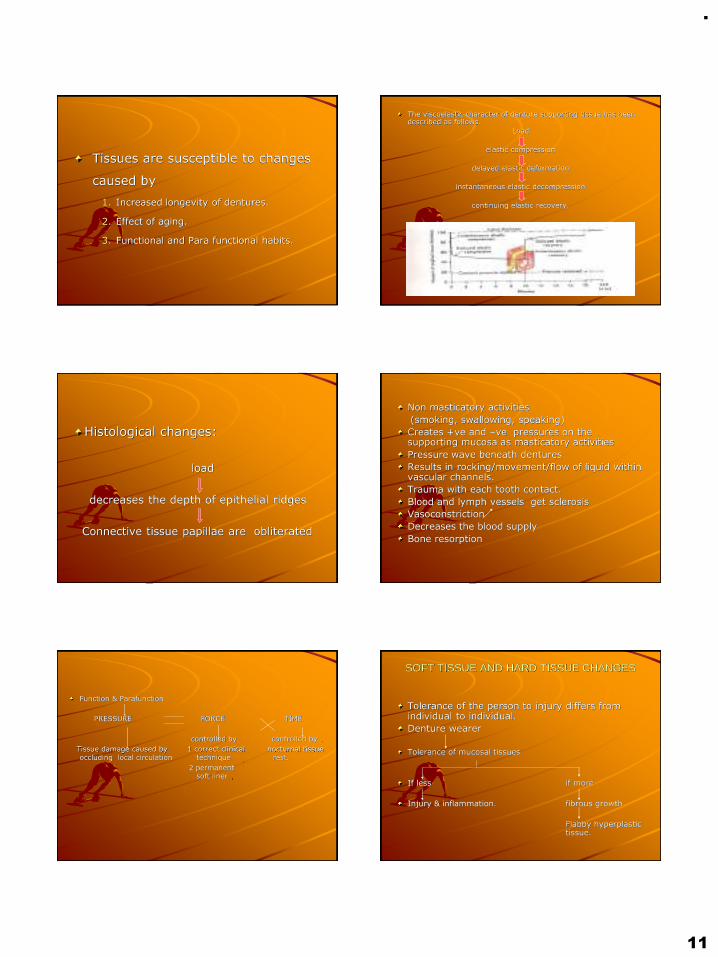
Tissues are susceptible to changes
caused by
1. Increased longevity of dentures.
2. Effect of aging.
3. Functional and Para functional habits.
The viscoelastic character of denture supporting tissue has been described as follows.
Load
elastic compression
delayed elastic deformation
instantaneous elastic decompression
continuing elastic recovery.
Histological changes:
load
decreases the depth of epithelial ridges
Connective tissue papillae are obliterated
Non masticatory activities
(smoking, swallowing, speaking)
Creates +ve and –ve pressures on the supporting mucosa as masticatory activities
Pressure wave beneath dentures
Results in rocking/movement/flow of liquid within vascular channels.
Trauma with each tooth contact.
Blood and lymph vessels get sclerosis
Vasoconstriction
Decreases the blood supply
Bone resorption
Function & Parafunction
PRESSURE FORCE TIME
controlled by controlled by
Tissue damage caused by 1 correct clinical nocturnal tissue occluding local circulation technique rest.
2 permanent soft liner
SOFT TISSUE AND HARD TISSUE CHANGES
Tolerance of the person to injury differs from individual to individual.
Denture wearer
Tolerance of mucosal tissues
If less if more
Injury & inflammation. fibrous growth
Flabby hyperplastic tissue.
.
12
Soft tissue hyperplasiaFibrous hyperplasia
Epulis fissuratum
Papillary hyperplasia
Inflammatory changesDenture stomatitis
Denture sore mouth
Stomatitis venenata
candidiasis
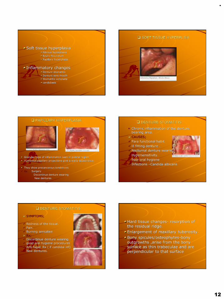
❑ SOFT TISSUE HYPERPLSIA
❑ PAPILLARY HYPERPLASIA
Granular type of inflammation seen in palatal region.
numerous papillary projections give a warty appearance.
They show precancerous tendencies
✓ Rx Surgery
Discontinue denture wearing
New dentures
❑ DENTURE STOMATITIS
▪ Chronic inflammation of the denture bearing area.
➢ CAUSES;
✓ Para functional habit.
✓ ill fitting denture .
✓ Nocturnal denture wearing.
✓ Hypersensitivity.
✓ Poor oral hygiene
✓ Infections –Candida albicans
❑ DENTURE STOMATITIS
➢ SYMPTOMS;
✓ Redness of the tissue.
✓ Pain.
✓ Burning sensation
➢ Rx;
✓ Discontinue denture wearing .
✓ good oral hygiene procedures
✓ Anti fugal Rx ( if candidal inf)
✓ New dentures.
Hard tissue changes- resorption of the residual ridge.
Enlargement of maxillary tuberosity.
Bony spicules/osteophytes-bony outgrowths ,arise from the bony surface as thin trabeculae and are perpendicular to that surface
.
13
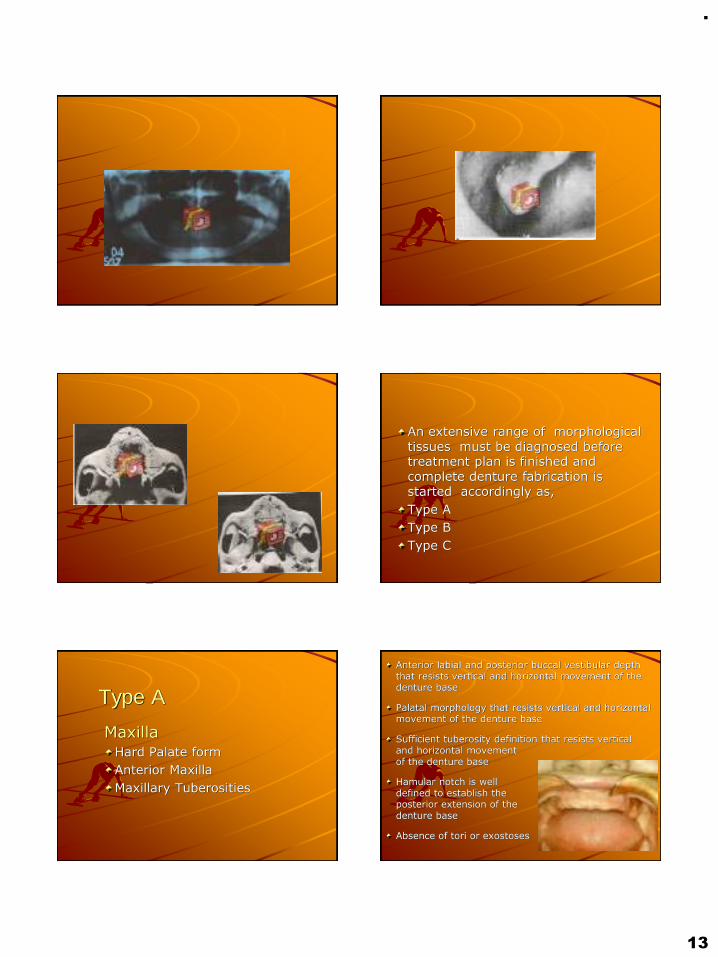
An extensive range of morphological tissues must be diagnosed before treatment plan is finished and complete denture fabrication is started accordingly as,
Type A
Type B
Type C
Type A
MaxillaHard Palate form
Anterior Maxilla
Maxillary Tuberosities
Anterior labial and posterior buccal vestibular depth that resists vertical and horizontal movement of the denture base
Palatal morphology that resists vertical and horizontal movement of the denture base
Sufficient tuberosity definition that resists vertical and horizontal movement of the denture base
Hamular notch is well defined to establish the posterior extension of the denture base
Absence of tori or exostoses

.
14
Type B
MaxillaHard Palate form
Residual Alveolar Ridge
–Anterior
–Posterior
Maxillary Tuberosities
Loss of posterior buccal vestibule
Tuberosity and hamular notch are poorly defined compromising delineation of the posterior extension of the denture base
Maxillary palatal and/or lateral tori are rounded and do not affect the posterior extension of the denture base
Palatal vault morphology that resists vertical and horizontal movement of the denture base
Type CMaxilla
Hard Palate form
Anterior Maxilla
Maxillary Tuberosities
Loss of anterior labial vestibule
Prominent midline suture
Maxillary palatal and/or lateral tori with bony undercuts that do not affect the posterior extension of the denture base
Hyperplastic, mobile anterior ridge that offers minimum support and stability of the denture base
Palatal vault morphology that offers minimal resistance to vertical and horizontal movement of the denture base
Reduction of the post malar space by the coronoid process during mandibular opening and/or excursive movements
Type DMaxilla
Hard Palate form
Residual alveolar ridge
–Anterior
–Posterior
Maxillary Tuberosities
Loss of anterior labial and posterior buccal vestibules
Maxillary palatal and/or lateral tori-rounded or undercut- that interferes with the posterior border of the denture
Hyperplastic, redundant anterior ridge
Palatal vault morphology that does not resist vertical or horizontal movement of the denture base
Prominent anterior nasal spine

.
15
Summary and conclusion
The scientific knowledge of denture supporting and influencing struture forms an integral part of denture fabrication. The macroscopic anotomy helps in the meticulous replacement of missing strutures, where as the knowledge at the microscopic level enhances the preservation of what remains. thus the health of the tissues can be preserved.
ReferencesZarb. Bolender:prosthodontic treatment for edentulous patients.12th edn.the c.v.mossby co.,2004.
Charles.m. heartwell.jr:syllabus of complete dentures 4th edn lea &fobiger, 1986.
Judson.c.hickey, charles.l.bolender.:bouchers prosthodontic treatment for edentulous patients.9th edn.the c. v. mossy co,1985
Sheldon winkler:essentials of complete dentures prosthodontics.2 edn ,w.b.sauders company,
Kolb, h.r:variable denture- limiting struture of the edentulous mouth.part 1:maxillary border areas,j. prosth. Dent.16,194,1966.
Curtight,d. e:tissue pressure under complete dentures.j. prosthet. Dent.35, 160-170,1976
Kapur,k:effect of complete dentures on alveolar mucosa. J.prosthet dent13:1030-1037,1963
Harold R.Ortman, Factors of bone resorption of the residual ridge,j.prosthet dent,may-june, 1962
Orbans:oral histology and embryology
Tencate:oral histology, development struture and function
Robert.l.engelmerier, the dental clinic of north america, complete dentures jan 1996

.
1
CALCIUMMETABOLISM
DR GYAN PRAKASH
CONTENTS:❑ Introduction
❑ Importance & Distribution of Ca++
❑ Functions
❑ Daily Requirements
❑ Sources
❑ Absorption of Calcium
❑ Hormonal control of ca++ metabolism
❑ Regulation of Ca++
❑ Excretion of Ca++
❑ Impairments in Blood calcium
❑ General and prosthodontic Mangement
❑ Nutritional management of geriatric patient
❑ Conclusion
❑ References
As dentists, it is vital for us to have a complete understanding of thegeneral metabolism of calcium as ithelps in the formation andmaintenance of the teeth and theirsupporting bony structure.
✓Approximately 99% of the total body weight of calcium is present in the skeleton.
✓ The remaining 1% is found in the cell membranes and extracellular fluid.
✓ It is this small percentage of calcium that is vital to all life processes.
FUNCTIONS OF CALCIUM:

.
2
1.Contributes to hardness of bone and is a
major component of teeth.2. Stabilises the cell membrane and their
permeability.3.Maintenance of excitability of nerve and
muscles.4. Normal skeletal and cardiac muscle
contraction.5.Blood coagulation – Ca++ is required for theconversion of many inactive enzymes inthe coagulation process.
Infants (< 1 year) = 300-500 mg/ day
Children (1 – 18 years) = 0.8-1.2 g/day
Adult men and women = 800 mg/day
Pregnancy and lactation = 1.0-2gm/day
Milk is a good source for calcium. Calcium content of cow
milk is about 100mg/100ml.
Egg, fish & vegetables are medium source for calcium.
Cereals (wheat, rice) contains small amount of
calcium. But cereals are the staple diet in India.
Therefore, cereals form the major source of calcium in
Indian diet.
Several different kinds of calcium compoundsare used in calcium supplements. Each compound contains varying amounts of themineral calcium.
Common calcium supplements may belabeled as:Calcium carbonate - Tums® and Caltrate®Calcium citrate- Citracal® and Solgar®
If the calcium in diet and from supplementsexceeds the tolerable upper limit, you couldincrease your risk of health problems, suchas:
➢Kidney stones➢Prostate cancer➢Constipation➢Calcium buildup in your bloodvessels➢ Impaired absorption of iron andzinc

.
3
Calcium absorption in the small intestine occurs byboth active & passivediffusion.
➢Uptake of calcium by active transport
predominates in: duodenum,jejunum
➢Simple diffusion predominates in: ileum
Most of the ingested calcium is normally eliminated inthe feces, although the kidneys have the capacity to excrete large amounts by reducing tubularreabsorption of calcium
VitaminD –Calcitriol induces the synthesis of the carrierprotein
(Calbindin) in the intestinal epithelial cells & so facilitates
the absorption of calcium.
Parathyroid hormones increases calcium transport
from the intestinal cells.
Amino acids, especially lysine & arginine increase absorption.
Lactose : enhance passive Ca uptake; its effect is valuable
because of it presence in milk.
Phytates — Phytates are substances found in someplant foods that can bind
calcium in the intestine and decrease its absorption.
Oxalates are present in some leafy vegetables whichcause formation of
insoluble calcium oxalates .
In malabsorption syndromes , fatty acid is not
absorbed , causing formation of insoluble calcium salt
of fatty acid .
High phosphate content will causeprecipitation as calcium phosphate.
Absorption is also decreased with increaseintake of protein & fiber in diet
This term is used to describe the amount of Ca++ either stored or lost by the body over aspecific period of time.
When the assimilation of calcium from dietarysources is less than the metabolic requirements and the obligatory losses , then calcium iswithdrawn from the skeleton to maintain the critical concentration of the element in the bloodand tissue fluids.
Calcium homeostasis is the mechanism by which
the body maintains adequate calcium levels.
Positive Ca2+ balance
Is seen in growing children, where intestinal Ca2+
absorption exceeds urinary excretion and the
difference is deposited in the growing bones.
.
4
Negative Ca2+balance
Is seen in women during pregnancy or lactation,
where intestinal Ca2+ absorption is less than
urinary excretion and the difference comes from
the maternal bones.
The primary source of available calcium is trabecular bone, not corticalbone.
The sites of trabecular bone which supply mobile calcium are the jaws, ribs, bodies of the vertebrae, and the ends of the long bones.
A significant finding from animal experimentation is that, when skeletal depletion of calcium occurs as a result of stimulation of theparathyroid gland, alveolar bone is affected first, the ribs and the vertebrae are affected second,and the long bones third.
Prolonged depletion results in disorganization and loss of trabeculae, followed by corticalremodeling or structural failure.
Acomplex set of interlocking mechanisms takesplace in order to allow man to survive major dietary Ca intake fluctuations. These mechanisms are mainly controlled by theendocrine systems.
Three main hormones acting at 3 differentsites are responsible for Ca metabolism.1.Vit. D3 - Bone.2.Parathormone - Kidney3.Calcitonin - Intestine
Physiologically active form of vitamin D is ahormone called calcitriol or 1,25 –dihydroxycholecalciferol (1,25 – DHCC).
It stimulates Ca uptake by osteoblasts of thebone and promotes calcification or mineralization and remodelling , thus increasing the blood calcium levels.
Acts mainly by increasing the synthesis of mRNA which directly increases the concentration of (CBP) Ca binding protein mainly in the tissues of the intestinal mucosa.
The CBP thereby binds with increased amount of Ca and allows increased Ca to be absorbed.
.
5
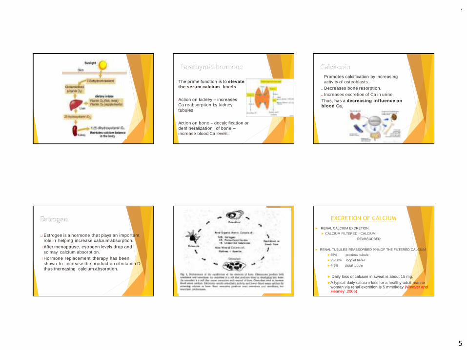
The prime function is to elevatethe serum calcium levels.
Action on kidney – increasesCa reabsorption by kidneytubules.
Action on bone – decalcification ordemineralization of bone –increase blood Ca levels.
Promotes calcification by increasingactivity of osteoblasts.
Decreases bone resorption.
Increases excretion of Ca in urine.Thus, has a decreasing influence onblood Ca.
Estrogen is a hormone that plays an importantrole in helping increase calcium absorption.
After menopause, estrogen levels drop andso may calcium absorption.Hormone replacement therapy has been shown to increase the production of vitamin Dthus increasing calcium absorption.
EXCRETION OF CALCIUM
RENAL CALCIUM EXCRETION
CALCIUM FILTERED - CALCIUM
REABSORBED
RENAL TUBULES REABSORBED 99% OF THE FILTERED CALCIUM
65% proximal tubule
25-30% loop of henle
4-9% distal tubule
Daily loss of calcium in sweat is about 15 mg.
A typical daily calcium loss for a healthy adult man or woman via renal excretion is 5 mmol/day (Weaver and Heaney ,2006)

.
6
Hypercalcemia - Increased level of Ca in theblood.
Symptoms- Tiredeness- Loss of appetite.- Nausea, vomitting.- Constipation.
Conditions in which it occurs- Hyperparathyroidism.- Acute osteoporosis.- Vit. D intoxication.- Thyrotoxicosis.
- Polyuria.- Dehydration.- Loss of muscle tone.-Decreased excitability of muscles and nerves.
Hypocalcemia - Decreased levels of Ca in the blood.
Below 8.8mg/dl mild
tremors
Less than 7.5mg/dl tetany
Symptoms- Tetany (Carpopedal spasm).
This occurs in cases of –- Insufficient Ca in the diet.- Hypoparathyroidism.- Insufficient vit. D in the diet.- Increase in calcitonin levels.
VIT-D DEFICIENCY
RICKETS
In children.
affect long bones in the body, ribs.
mineralization failure , due to lack of Ca.
the cartilaginous form of bone is said to persist.
localized areas of cartilage proliferation due to its continuous growth
result in the bowing of legs – knock knees
OSTEOMALACIA
In adults.
affects the flat bones in the body.
Especially seen in post and menopausal women .
who have a decreased dietary Ca intake.
And decreased exposure to the sun resulting in increased removal of Ca from the bone causing softening of the skeleton and its distortion.
Dental findings
Development of abnormality in enamel and dentin.
Delayed eruption of teeth.
Mal-alignment of teeth.
Higher caries index.
Wider predentine zone.
Increased amount of inter-globular dentin.
Treatment :Supply adequate amount of Ca and phosphate in diet and administration of large amounts of Vit. D
Dental findings
Severe periodontitis
PARATHYROID HORMONE:
Hyperparathyroidism
Increases levels of PTH due to an adenoma of the parathyroid glands.
C/F: Pathologic fracture of bones due to increased mobilization
of Ca from bone resulting in osteitis fibrosa cystica. Large punched out cystic area of bone.
Joint stiffness. Urinary tract stones. Muscle weakness. Thirst. Polyuria Anorexia. Weight loss.
Dental findings
Malocclusion seen due to definite drifting of teeth causing spacing (this occurs as a result of increased loss of Ca from the bone, there is an absolute attempt to new bone formation and repair resulting in spacing).
Radiographically
Areas of radiolucency seen in bone.
Loss of lamina dura present.
Treatment
Removal of cause
.
7
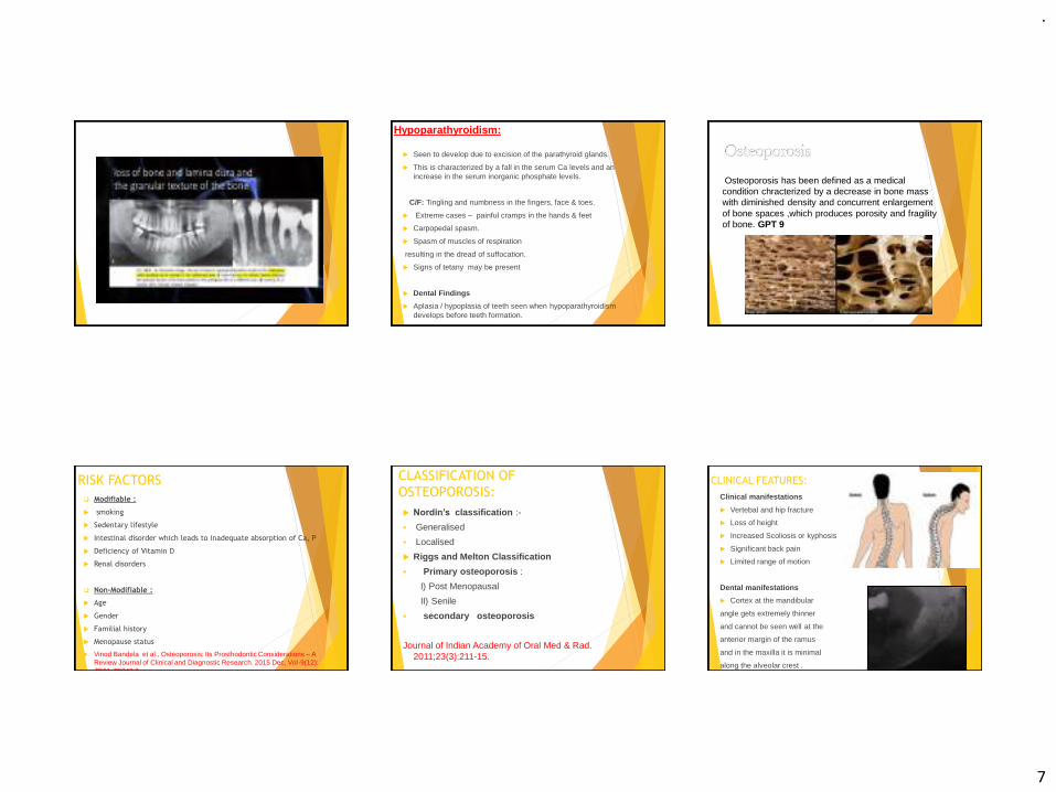
Hypoparathyroidism:
Seen to develop due to excision of the parathyroid glands.
This is characterized by a fall in the serum Ca levels and an increase in the serum inorganic phosphate levels.
C/F: Tingling and numbness in the fingers, face & toes.
Extreme cases – painful cramps in the hands & feet
Carpopedal spasm.
Spasm of muscles of respiration
resulting in the dread of suffocation.
Signs of tetany may be present
Dental Findings
Aplasia / hypoplasia of teeth seen when hypoparathyroidism develops before teeth formation.
Osteoporosis has been defined as a medical condition chracterized by a decrease in bone mass with diminished density and concurrent enlargement of bone spaces ,which produces porosity and fragility of bone. GPT 9
RISK FACTORS
❑ Modifiable :
smoking
Sedentary lifestyle
Intestinal disorder which leads to inadequate absorption of Ca, P
Deficiency of Vitamin D
Renal disorders
❑ Non-Modifiable :
Age
Gender
Familial history
Menopause status
Vinod Bandela et al., Osteoporosis: Its Prosthodontic Considerations – A Review Journal of Clinical and Diagnostic Research. 2015 Dec, Vol-9(12): ZE01-ZE042 2
CLASSIFICATION OF
OSTEOPOROSIS:
Nordin’s classification :-
▪ Generalised
▪ Localised
Riggs and Melton Classification
▪ Primary osteoporosis :
I) Post Menopausal
II) Senile
▪ secondary osteoporosis
Journal of Indian Academy of Oral Med & Rad. 2011;23(3):211-15.
CLINICAL FEATURES:
Clinical manifestations
Vertebal and hip fracture
Loss of height
Increased Scoliosis or kyphosis
Significant back pain
Limited range of motion
Dental manifestations
Cortex at the mandibular
angle gets extremely thinner
and cannot be seen well at the
anterior margin of the ramus
and in the maxilla it is minimal
along the alveolar crest .

.
8
Calcium metabolism and osteoporotic ridge resorption R. P. Blank, H. A. Diehl, G. T. Ballard, and
R. C. Melendez (JPD NOV 1987)
Osteoporosis may be defined simplyas a condition of insufficient bone.
This deficiency undermines skeletal strength, resulting in fractures thatoccur with minimal stress in the spine,distal radius and ulna, and in thefemoral neck.
Of the 190,000 hip fractures occurringannually, 80% are in postmenopausalwomen.
The relationship of osteoporosis to alveolar and residual ridge resportion is of justifiable concern to the dental profession.
Although generalized bone loss is characteristic of osteoporosis, the first sign may be alveolar bone loss, followed by loss in the vertebrae and long bones.
It may be difficult to treat edentulous patients who manifest the excessive residual ridge resorption often associated with osteoporosis.
By the time osteoporosis is generally diagnosed, 50% to 75% of the original bone material has been lost from the skeleton.
Increasing calcium intake by means of dairy foods and supplementation is the method most practiced in the prevention and treatment of osteoporosis to optimize calcium balance.
Studies indicate protection against age-related boneloss in the hand bones and residual ridge bone withincreased calcium intake.
In contrast, several studies reported no benefit to bone density from daily calcium supplementation.
This variance in reported data helps to explain the wide range in recommended dietary calcium intake from various health organizations.
The current recommended dietary allowance (RDA) is 800 mg of calcium/day,
The most recent National Institutes of Health (NIH) proposal calls for 1000 to 1500 mg of daily calcium.
The World Health Organization (WHO) recommendation is only 400 to 500 mg of calcium/day.
Calcium intake in most populations around the world is 300 to 500 mg/day without any evidence of osteoporosis.
Bone resorption of residual ridges is common. The rate of resorption varies among different individuals and within the same individual at different times.
Factors related to the rate of resorption are divided into anatomic, metabolic, functional, and prosthetic factors.

.
9
✓ Anatomic factors include the size, shape,and density of ridges, the thickness and character of the mucosa covering, and theridge relationships.
✓ Metabolic factors include all of the multiple nutritional, hormonal, and other metabolicfactors which influence the relative cellularactivity of the boneforming cells (osteoblasts) and the bone resorbing cells (osteoclasts).
Functional factors include the frequency, intensity, duration, and direction of forces applied to bone which are translated intocellular activity, resulting in either boneformation or bone resorption.
Prosthetic factors include the myriad oftechniques, materials, concepts, principles,and practices which are incorporated into theprostheses.
Although the various factors can be divided into these four groups for academic purposes, they are all interrelated.
The diets of subjects with minimal bone resorption were compared with the diets of subjects with severe alveolar destruction.
The results indicate a positive correlation among low calcium intake, and severe ridge resorption.
Emphasis was placed on the importance ofconsidering dietary factors in the diagnosis and treatment of prosthodontic problemswhich arise from the excessive resorption of residual ridges.
It was concluded that systemic conditions are important in the etiology of residual ridgeresorption. The resistance of bone tomechanical stresses depends on itsphysiologic state.
Of the many systemic influences which affect thebone responses of patients, dietary factors maybe subject to the dentist’s control just as are factors of denture construction.
Nutritional deficiencies andimbalances, as well as mechanical factors, should receive consideration in diagnosis and treatment planning for prosthodonticpatients.

.
10
PROSTHODONTIC
MANAGEMENT:
women above 50 years with osteoporosis required new dentures three times more frequently than women of same age.(Humphries et al., )
Modify the treatment plan with specific precautions to reduce the stresses
Mucostatic or open mouth impression techniques, selective pressure impression technique, should be employed .
semi anatomic or non anatomic teeth with narrow buccolingual width should be selected
Optimal use of soft liners are indicated .
extended tissue intervals by keeping the dentures out of mouth for 10 hours a day can be advised.
While fabricating FPD in periodontaly compromised abutments it may accelerate the bone loss in osteoporotic patients.
fabrication of FPD should follow treatment of osteoporosis rather than preceding it.
DENTAL DEFECTS:
Enamel hypoplasia
Multiple unerupted teeth-Hypothyroidism
Absense of lamina dura-Vit D Rickets
(Hypophosphatemia)
Pre mature exfoliation-Hypophosphatemia
Delayed eruption of teeth-Hypothyroidism
CALCIUM MANAGEMENT OF GERIATRIC
PATIENTS:
DIET CHART FOR GERIATRIC PATIENTS:(manual of
dietary guidelines for indians , national institute of
nutrition 2011)
Bed tea -1-2 cups of tea + 1 teaspoon of sugar
Breakfast -1 glass of toned milk(200ml)
2-3 slices of wheat bread /chappati
paneer 25 gms /egg white 1
10:30 AM : Buttermilk 1 glass
Lunch : salad soup
chapati 2-3 (20 gms ),rice ,dal (1 bowl) , curd (1 bowl), green vegetables
(1 bowl), soya musturd cooking oil (1 tbs ), fresh fruit100(gms).
3:30PM: 1cup of tea or coffee
biscuit 2-3/ sprouts/upma 1 serving
Dinner : Salad
chappati 2 medium ,rice ,curd,dal,green vegetables 1 servings, cooking oil 2
tsp
Bed time : toned milk 1 cup (150 ml)
.
11
CONCLUSION:
Ca and PO4 are important minerals that are required in minimal amounts for basic activities in the body like the normal ionic Ca levels in the plasma is required for proper bone mineralization and maintenance of cell membrane integrity. The plasma Ca levels need to be regulated within a very narrow range because of its marked effect on neuromuscular and cardiac excitability.
Biochemistry U. Satyanarayan
Sheldon Winkler ,A.I.T.B.S. Publishers , Essentials of complete denture Prosthodontics,2nd edition
Calcium metabolism and osteoporotic ridge resorption
R. P. Blank, H. A. Diehl, G. T. Ballard, and R. C. Melendez (JPD Nov 1987)
Some clinical factors related to rate of resorption of residual ridges ; Atwood (JPD Aug 2001)
Studies of residual ridge resorption. The relationship of dietary calcium and phosphorus toresidual ridge resorption ; Wical and Swoope (JPD July 1974)
Physiology- by Ganong
Medical physiology- by Chaudhary
Journal of Indian Academy of Oral Med & Rad. 2011;23(3):211-15.
manual of dietary guidelines for indians , national institute of nutrition 2011

.
1
Surgical aspects
of dental implants
DEFINITION
The Glossary of Prosthodontic Terms defines an implant as “a
prosthetic device or alloplastic material implanted into the oral
tissues beneath the mucosal or/and periosteal layer, and /or
within the bone to provide retention and support for a fixed or
removable prosthesis.”
CLASSIFICATION OF DENTAL IMPLANTS
BASED ON RELATION TO BONE FORM
ENDOSTEAL
SUBPERIOSTEAL
TRANSOSSEOUS
BASED ON SHAPE
BLADE FORM
ROOT FORM
BASED ON MATERIAL USED
METALLIC
CERAMIC
TYPES OF DENTAL IMPLANTS
Several types of implants have been used throughout history.
They include
Endosteal implants that are placed into the bone
Subperiosteal implants that are placed on or upon the bone
Transosteal implants that are placed through the bone
The subperiosteal implant is retained by
periosteal integration In which the outer
layer of periosteum provides dense fibrous
envelope & anchors the implant to bone
through sharpeys` fibers

.
2
Used only in the anterior mandible
Indication :
In the very atrophic mandible
Due to the complex nature of the surgical approach this implant is not used frequently.
Transosteal implantsEndosteal implants:
They are surgically placed within alveolar and basal bone
subdivided into
Root formimplants include those that approximate the shape and dimensions of tooth roots (called root form implants)
Blade formthose that are plates of metal (called blade implants)
Ramus formthose that are metal frameworks where only a portion of the metal is implanted
into bone (ramus frame implants).
The Endosteal Blade implant was introduced in 1967 by Leonard Linkowand also by Ralph and Harold Roberts
Shape:
as the name suggests a metal / blade in cross-section
Available in 1 stage / 2 stage forms
BLADE FORM
2.5mm in width8 to 15mm in depth
15 to 30mm in length
They are technique- sensitive
They have an external attachment bar that runs from ascending ramus to ascending ramus
Posteriorly on each side they have an endosteal extensions, inserts into available bone within ascending ramus
Anteriorly it has plate / blade extension ,is inserted into symphysis
RAMUS FORM
IMPLANT COMPONENTS
IMPLANT COMPONENTS
Implant body
Sealing screw
Healing cap
Abutement
Impression post
Laboratory analogues
Waxing sleeves
Prosthesis retaining screw

.
3
1.Implant body:
Implant body is the endosteal dental implant
that is placed within the bone during first
stage surgery.
It may be either a threaded or non threaded
cylinder It is either titanium alloy with or
without hydroxyapatite coating.
2.Sealing screw :
A screw is placed in the implant during the healing phase following stage –one surgery.
Prevents the growth of the tissue over the edge of the implant.
Sealing screw
3.Healing cap
Healing cap is dome –shaped screw .
They may range in length from 2 to 10mm and projects through the soft tissue into the oral cavity.
Made up of resin such as polyoxymethyline or the titanium metals
4.Abutment:
Screws directly into implant support prosthesis.
Primary component which provides retention to the prosthesis.
5.Impression post:
Facilitates transfer of intra oral location of abutment to similar position in laboratory cast.It screws directly into fixture / into abutment.once impression post is in place ,an impression is made.
6.Laboratory analog:
Component to represent either implant or abutment in
laboratory cast.
It screws onto the impression post after it has been
removed from mouth & placed back into impression
before pouring
7. Waxing sleeve :
Is attached to the abutment by the prosthesis retaining screw on a laboratory model.
8. Prosthesis retaining screw :
Penetrates the fixed restoration and secures to the abutment
Prosthesis retaining screw
IMPLANT ABUTMENT
Anchorage component:that is embedded in bone (the implant).
Prosthetic component
that attaches to the implant
segmented
non-segmented
MULTIPLE PIECES CONNECTEDTOGETHER
ONE PIECE
Segmented prosthetic component:
an abutment is attached to the implant using a screw and the definitive crown is then attached to the abutment.
Non segmented / one piece :
attaches to the implant by using screw that passes the occludingSurface & threads into implant

.
4
When abutments are used, the crowns or fixed partial dentures can either be
cemented to the abutments
or
attached to the abutment via screws
The following factors determine whether intermediary abutments are used with single crowns and fixed partial dentures or whether they can be attached
directly to the implants.
1.Implant angulation
2. Interocclusal space
3. Cost
Bone to implant interface
Two basic theories
1.Fibro-osseous integration by Linkow, James & Weis
2 Osseointegration by Branemark
EVENTS AFTER IMPLANT PLACEMENT
Bone Necrosis
• About 1 millimeter of cortical bone adjacent to the osseous wound (osteotomy site) undergoes post surgical necrosis in spite of careful surgical technique.
Three phases have been described in the development of the bone-implant interface ------
1.stabilization phase
subendosteal and subperiosteal calluses form and adhere to the implant surface.
2.THE STERENGTH PHASE
The implant is stabilized
The process of resorption begins
Stronger, weight bearing bone is formed (lamellar bone)
Osteoclasts resorb nonvital bone and restore it with new lamellar bone
3. THE DURABILITY PHASE
extensive remodeling occur and additional strength is developed.
With remodeling and proper prosthodontic function, the interface bone will tend to show very mature osteonal and lamellated bone
Destruction of Osseointegration
The main contributing factor to bone resorption are
1. local inflammation from plaque
Direct action of plaque products induces formation of
osteoclasts, destroys bone through a non cellular
mechanism
2.Trauma from occlusion
Stimulate gingival cells, which release mediators for
osteoclast formation..
Factors influencing Osseointegration
Biomaterial for dental implant
Surface composition and structure
Implant design
Heat
Contamination
Primary stability or initial stability
Bone quality
Epithelial down growth
Loading
A minimum of 3 month healing in mandible and 6 months in maxilla is necessary before load is applied

.
5
Bone density classification (Misch)
SURGICAL ASPECTS OF
DENTAL IMPLANTS
protocol, based on experience
of the Branemark implant system,
preoperative examination 1. primary judgment (prosthetic level) 2. secondary assessment (surgical level) 3. treatment planning (combined surgical-
prosthetic level)
minimum bone volume needed for standard implants of the Branemark System.
Bone drillingBone tissue should not be exposed to adverse friction
heat formation during drilling (Branemark et al. 1985).
This may easily take place, as the threshold level for osteocyte damage lies around 47°C, i.e. only about 10°C above the body temperature (Eriksson & Adell 1986).
Implant position with regard to the anatomic situation, the implant
should preferably be placed in tooth position , both in a mesiodistal and in a buccolingual direction.

.
6
Implants should never be placed in the midline of the maxilla or the mandible, as in these positions they may either expand the suture, as between the two maxillae, and/or may compromise the esthetics.
the implants should not be placed into important structures such as nerves, tooth roots and jaw cavities either, as no damage of surrounding tissues can be accepted just because of the wish to insert implants for prosthetic anchorage
Surgical Equipments:
Surgical drapes, towel clips, gauze Mouth mirror, dental explorer Scalpels Periosteal elevators, sharp curettes Flap retractors Drills and burrs with internal or external cooling systems Implant system kit including the sterile implant to be placed Needle holder, suture material Sutures for preparation of tissues and for cutting sutures Tissue holding forceps Mallet Measuring device Sterile normal saline
Instrument tray for implant placement
Tray for uncovering,, abutment adaptation
Controller set, drill equipment
Single stage implant:
This technique involves only single surgical procedure.
The implant fixture is inserted with a prosthetic post,
immediately in the post-operative period.
The implant may be loaded in the post-operative period.
Two stage implant:
This requires two surgical procedures.
In the first surgery, the implant body is seated into bone and completely covered by mucoperiosteal flaps and allowed for healing.
In the second surgery, implants are uncovered to receive the prosthetic component.
Advantage : Allows osseous healing of the implant without any loading force
STEPS IN PLACEMENT OF IMPLANT1.Incision
2.Reflection of mucoperiosteal flap
3.Preperation of osteotomy & insertion of implant
4.Uncovering of implant after healing phase
5.Prosthetic component placement
6.loading of implant
.
7
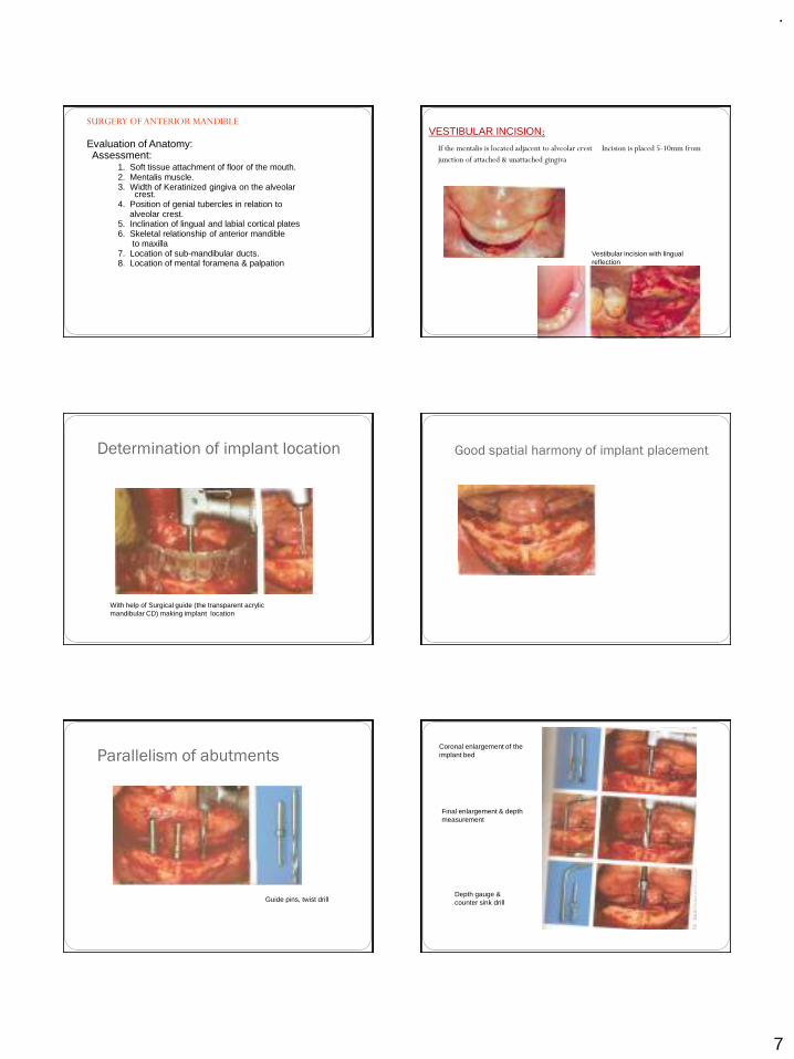
SURGERY OF ANTERIOR MANDIBLE
Evaluation of Anatomy:Assessment:
1. Soft tissue attachment of floor of the mouth. 2. Mentalis muscle.3. Width of Keratinized gingiva on the alveolar
crest.4. Position of genial tubercles in relation to
alveolar crest.5. Inclination of lingual and labial cortical plates6. Skeletal relationship of anterior mandible
to maxilla7. Location of sub-mandibular ducts.8. Location of mental foramena & palpation
VESTIBULAR INCISION:
If the mentalis is located adjacent to alveolar crest Incision is placed 5-10mm from
junction of attached & unattached gingiva
Vestibular incision with lingual reflection
Determination of implant location
With help of Surgical guide (the transparent acrylic mandibular CD) making implant location
Good spatial harmony of implant placement
Parallelism of abutments
Guide pins, twist drill
Coronal enlargement of the implant bed
Final enlargement & depth measurement
Depth gauge & counter sink drill

.
8
Checking position and axis orientation
Guide pins
Tightening with cylinder wrench
Removing the seating posts
Placement of cover screws
Suture closure
.A post operative radiographic evaluation
should be taken at this time to confirm implant placement and proper seating of the healing screw.
Healing Time
The post-operative bone healing time depends on several factors
1.Quantity and quality of bone
2.Implant stability
3.Health of the patient
4.Clinical judgment and experience of the surgeon.
A general guide for healing time is:
• Type I bone (3 to 4 months)
• Type II bone (4 to 5 months)
• Type III bone (5 to 6 months)
• Type IV bone (6 to 8 months)
UNCOVERING OF IMPLANT
In two stage implant
the 2nd surgical procedure is to uncover the implant after healing phase
Usually done after--3 months in mandible
6 months in maxilla
VARIOUS TECHNIQUES ARE USED
Crestal incision
Tissue punch / Soft tissue punch
Electro surgical uncovering
Once the implant is uncovered
Osseous union of implant is checked
Peri-implant soft tissue is checked
Uncovering of implant
Removal of cover screws

.
9
Seating of prosthesis
COMPLICATIONS ASSOCIATED WITH IMPLANTS
1.SURGICAL COMPLICATIONS
1.Hematomas/Edema/Ecchymosis
2. Nerve damage3.Mandibular Fracture
4.Adjacent Tooth Devitalization
5.Life-Threatening Hemorrhage
6.Air Emboli
2.EFFECT OF IMPLANT LENGTH
Failure occurs when the implants are short (7 & 10 millimeters long).
3.EFFECT OF IMPLANT PLACEMENT IN TYPE IV BONE
Higher failure rates
Hematoma Nerve damage( injury to inferior alveolar nerve)
Opening the nasal or maxillary sinuses 4.PROSTHETIC RELATED
2.Opposing Prosthesis Fracture
3.Prosthesis Screw Loosening 4.Abutment Screw Loosening
5.Metal Framework Fracture
6.Implant Fracture
5.PERI-IMPLANT SOFT TISSUECOMPLICATIONS
1.Implant Fenestration/Dehiscence
2.Gingival Inflammation/Proliferation
3.Fistulas
Dehiscence
.Implant Fenestration
.
10
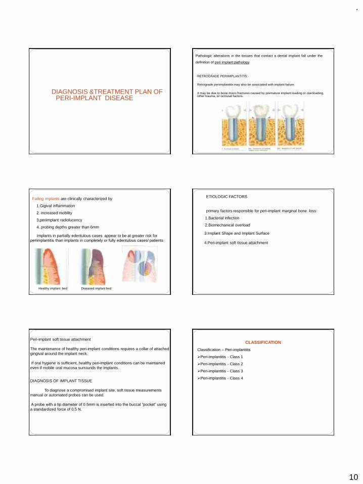
DIAGNOSIS &TREATMENT PLAN OF PERI-IMPLANT DISEASE
Pathologic alterations in the tissues that contact a dental implant fall under the
definition of peri implant pathology.
RETROGRADE PERIIMPLANTITIS:-
Retrograde periimplantitis may also be associated with implant failure.
It may be due to bone micro fractures caused by premature implant loading or overloading, other trauma, or occlusal factors.
Failing implants are clinically characterized by
1.Gigival inflammation
2. increased mobility
3.periimplant radiolucency
4..probing depths greater than 6mm
Implants in partially edentulous cases appear to be at greater risk for periimplantitis than implants in completely or fully edentulous cases/ patients
Healthy implant bed Diseased implant bed
ETIOLOGIC FACTORS
primary factors responsible for peri-implant marginal bone loss:
1.Bacterial infection
2.Biomechanical overload
3.Implant Shape and Implant Surface
4.Peri-implant soft tissue attachment
Peri-implant soft tissue attachment
The maintenance of healthy peri-implant conditions requires a collar of attached gingival around the implant neck.
If oral hygiene is sufficient, healthy peri-implant conditions can be maintained even if mobile oral mucosa surrounds the implants.
DIAGNOSIS OF IMPLANT TISSUE
To diagnose a compromised implant site, soft tissue measurements manual or automated probes can be used.
A probe with a tip diameter of 0.5mm is inserted into the buccal “pocket” using
a standardized force of 0.5 N.
CLASSIFICATION
Classification – Peri-implantitis
➢Peri-implantitis - Class 1
➢Peri-implantitis - Class 2
➢Peri-implantitis - Class 3
➢Peri-implantitis - Class 4

.
11
Peri-implantitis - Class 1
Slight horizontal bone loss with minimal peri-implant defects
Peri-implantitis class 2
Moderate horizontal bone loss with isolated vertical defects.
Peri-implantitis class 3
Moderate to advanced horizontal bone loss with broad, circular bony defects.
Peri-implantitis class 4
Advanced horizontal bone loss with broad, circumferentialvertical defects, as well as loss of the oral and/or vestibular bonywall.
MANAGEMENT
The first phase involves 1.an analysis of the fit of the prothesis2. the number and position of the implants3.an occlusal evaluation.
Prosthesis design changes, improvement of implant number and position, can arrest the progression of peri – implant tissue breakdown.
The second phaseto eliminate deep peri – implant soft tissue pockets to regenerate bone around the implant
The treatment involves ANTI-INFECTIVE THERAPY
1. The local removal of plaque deposits with plastic instruments
2. Polishing of all accessible surfaces with pumice
3. Subgingival irrigation of all periimplant pockets with 0.12% chlorhexidine
4. Systemic antimicrobial therapy for 10 consecutive days
The second phase involves the surgical procedure.
.
12
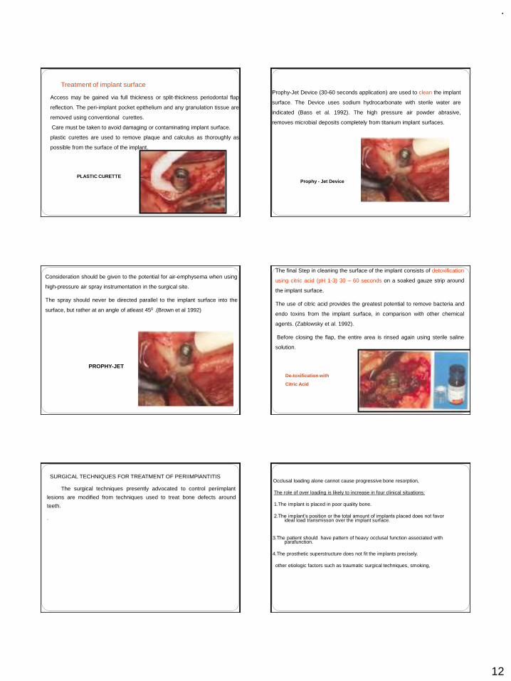
Access may be gained via full thickness or split-thickness periodontal flap
reflection. The peri-implant pocket epithelium and any granulation tissue are
removed using conventional curettes.
Care must be taken to avoid damaging or contaminating implant surface.
plastic curettes are used to remove plaque and calculus as thoroughly as
possible from the surface of the implant.
PLASTIC CURETTE
Treatment of implant surfaceProphy-Jet Device (30-60 seconds application) are used to clean the implant
surface. The Device uses sodium hydrocarbonate with sterile water are
indicated (Bass et al. 1992). The high pressure air powder abrasive,
removes microbial deposits completely from titanium implant surfaces.
Prophy - Jet Device
Consideration should be given to the potential for air-emphysema when using
high-pressure air spray instrumentation in the surgical site.
The spray should never be directed parallel to the implant surface into the
surface, but rather at an angle of atleast 450 .(Brown et al 1992)
PROPHY-JET
The final Step in cleaning the surface of the implant consists of detoxification
using citric acid (pH 1-3) 30 – 60 seconds on a soaked gauze strip around
the implant surface.
The use of citric acid provides the greatest potential to remove bacteria and
endo toxins from the implant surface, in comparison with other chemical
agents. (Zablowsky et al. 1992).
Before closing the flap, the entire area is rinsed again using sterile saline
solution.
De-toxification with
Citric Acid
SURGICAL TECHNIQUES FOR TREATMENT OF PERIIMPlANTITIS
The surgical techniques presently advocated to control periimplant
lesions are modified from techniques used to treat bone defects around
teeth.
.
Occlusal loading alone cannot cause progressive bone resorption,
The role of over loading is likely to increase in four clinical situations:
1.The implant is placed in poor quality bone.
2.The implant’s position or the total amount of implants placed does not favor ideal load transmisson over the implant surface.
3.The patient should have pattern of heavy occlusal function associated with parafunction.
4.The prosthetic superstructure does not fit the implants precisely.
other etiologic factors such as traumatic surgical techniques, smoking,

.
13
Occlusal loading alone cannot cause progressive bone resorption,
The role of over loading is likely to increase in four clinical situations:
1.The implant is placed in poor quality bone.
2.The implant’s position or the total amount of implants placed does not favor ideal load transmisson over the implant surface.
3.The patient shld have pattern of heavy occlusal function associated with parafunction.
4.The prosthetic superstructure does not fit the implants precisely.
other etiologic factors such as traumatic surgical techniques, smoking,
The ressective therapy is used to
1.Reduce pockets 2.Correct negative osseous architecture and rough implant surfaces3. Increase the area of keratinized gingiva if needed.
The regenerative therapy is also used to reduce pockets but with the goal of regeneration of lost bone tissue
PERI –IMPLANT RESECTIVE THERAPY
Apically positioned flap and osseous resective therapy are used to correct
horizontal bone loss and moderate vertical bone defects
With the flap raised
1. Degranulation of the osseous defect is performed. Care should be
taken to avoid contact between the implant and metal instruments.
2.An implant surface is prepared with chemicals and air abrasives. It is
done by applying the air spray of the air-powder abrasive for a maximum
time of 60 seconds on the implant surface, followed by copious irrigation
with saline solution.
3.Then supersaturated citric acid is applied for 30 seconds, followed
again by irrigation with saline
IMPLANTOPLASTY
The process to level the bone and apically position the soft tissues during
surgical treatment for peri-implantitis leads to exposure of the rough surface
of the implant. Such rough surface tends to accumulate plaque, So they
should be smoothed and polished. Diamond stones with copious cooling
can be used to grind away plasma-spray coatings or threads on the implant
surface, with final polishing accomplished using rubber disks
Implantoplasty
Implantoplasty remains the single effective method for reducing plaque accumulation
PERI – IMPLANT REGENERATIVE THERAPY:
To accomplish regeneration of lost bone tissue and reosseointegration, guided bone regeneration (GBR) and bone graft techniques have been suggested.

.
14
ADVANCED SURGICAL PROCEDURES
GBR TECHNIQUEINCISION &FLAP REFLECTION
PLACEMENT OF membrane
OSSIFICATION OF DEFECT
GBR TECHNIQUE DEHISCENCE
RIDGE AUGMENTATION PROCEDURE
(2 STEPS)
RIDGE DEFECT
GBR TECHNIQUE
SURGERY FOR MEMBRANE REMOAL
TREATMENT RESULT
IMPLANT PLACEMENT
SINUS LIFT PRIMARY INCISION
PREPARING BONY WINDOW
AUGMENTATION MATERIAL
ROLES IN IMPLANT MAINTENANCE `
PATIENTS `ROLE
1. Plaque control of 85%.
2. Use of interdental (ID) brushes,hand and
motorized.(Proxa-Brush,Oral-B Brush,Rota-Dent,Sonic).
3. Dip brushes in chlorhexidine,0.12% (Peridex,Periogard).
4. Use of flosses,,tapes,dipped in chlorhexidine (Super-
Floss,Perio-Floss,G-Floss)
5. If patient has tooth-colored materials,composites,sand so
on, use a cotton swab dipped in chlorhexidine.

.
15
HYGIENIST ROLE
1. Check plaque control effectiveness (85%).
2. Check for inflammatory changes
3. IF pathology is present,probe gently with plastic probe
(sensor).
4. Scale supragingivally only (or slightly subgingivally).
5. Check for problems such as loose suprastructure.
6. No need to probe if no pathology is present.
CLINICAL ROLE
1.Check every 3 or 4 months
2.Check for 85% plaque control effectiveness.
3. Expose radiographs every 12 to 18 months if no pathology is present and
as needed pathology is present.
4. Is suprastructure is retrievable, remove and clean the
ultrasonic every 10 to 24 months.
5. If implant needs it repair, degranulate, detoxify and graft with guided bone
regeneration (GBR) if necessary.
REFERENCES
1.CLINICAL PERIODONTOLOGY 10TH EDITION –CARRANZA
2.CLINICAL PERIODONTOLOGY AND IMPLANTOGY 5TH EDITION-JAN LINDHE
3.IMPLANTOLOGY—COLOR -ATLAS-SPIKEERANN
4.PRINCIPLES AND PRACTICE OF IMPLANT DENTISTRY-------WEISS
5.GOOGLE NET SEARCH
.
1
Good Morning
IMPRESSION PROCEDURE FOR COMPLETE DENTURE
Dr. GYAN PRAKASH
Contents Introduction Purpose of the seminar History Review of literature Basic requirements of impression making Principles of impression making Classification of impression techniques Various impression techniques Steps in impression making Primary impression making Border molding and secondary impression making Impression techniques in compromised situations Summary and conclusion References
THE JOURNEY OF A THOUSAND MILES BEGINS WITH ONE STEP
Iao Tsu
INTRODUCTION
The beginning of a good denture starts with making of a good impression,so a good impression is a stepping stone
My objective in this presentation is to bring to your attention;considerations that appear to me to be basic and fundamental in impression making
Purpose of the seminar
Complete denture impression procedures are perhaps onephase on which much has been spoken about. Theliterature on the subject shows a persistent disagreementever since 1850.
Much of this confusion results from the fact that manyimpression procedures have been developed on empiricalbasis.
Many have used the available knowledge of functional andhistological anatomy for the development of theirprocedures, but the variation in these techniques indicate awide difference in interpretation of the foundation ofdentures.
Whatever the method used it is generally agreed that goodimpressions are basic for the construction of a gooddenture.

.
2
“Ideal impression must be in the mind of the dentist before it
is in his hand. He must literally make the impression rather than take it”
- M.M. De Van
History of complete denture making: 1711 Matthian G. Purman introduced the use of
wax. 1844 Plaster of paris was first used as an
impression material. 1848: gutta percha was introduced as a impression
material. 1845-1899 concepts of atmospheric pressure,
maximum extension of denture bearing area, equaldistribution of pressure and close adaptation of thedenture bearing tissues were stressed.
History contd…
1928 Pierre Fauchard made dentures by measuringthe mouth with compasses and cutting bone intoan approximate shape.
1896 Green brothers introduced mucocompressivetheory.
1900-1929 Concepts like Rebase impressions,border molding and techniques for flabby tissueswere introduced.
1930-1940 This era recognised the anatomy of thedenture bearing areas, and of muscle physiologyas related to impression procedures. This isevident by descriptions of border molding ofdentures. Several new impression materials wereintroduced : reversible hydrocolloids, zinc oxideeugenol and zinc oxide and oil of cloves.
1950-1964 more emphasis on biologic factor of impression making was given.
1951 Boucher introduced selective pressure theory.
1965-1980 new techniques to manage compromised situations were introduced.
New techniques are periodically been formulated to overcome the drawbacks faced.
Review of LiteratureFischer in 1951 laid down six fundamental rules for making an impressionRadiographs ,visual and digital examination
Surgical correction
Required extension outline
Required retention outline
Required adaptation
Location and position of variable tissue displaceability

.
3
A critical analysis of Mid-century impression techniques for full dentures Boucher in 1951 – he classified impression
techniques1. Based on the use of actual anatomy of the individual
patient or on arbitrary landmarksAnatomic or Arbitrary
2. Based upon the mouth position while the impression ismade.Open mouth or closed mouth
3. Based upon the relative amount of pressure exertedon the tissues by the impression material at the timeof setting.Pressure, non pressure or selective pressure
Impression by the use ofsubatmospheric pressure – Milo V.Kubalek, Bert C. Buffington (1966) The objective of this technique is to reduce the stress on
any given tissue by increasing the load bearing area. To realize the idea, the form of tissues must be recorded
both vertically and laterally so that all surfaces can bear anequal load and vacustatic technique is an attempt toachieve this.
When a controlled partial vacuum is established, animpression tray specially built for the patient is maintainedin the mouth without direct mechanical support of anykind.
The difference between subatmospheric pressure withinthe tray and atmospheric pressure outside is all thatretained the impression in a static position.
It denotes the equilibrium of forces which results when acontrolled vacuum is established.
Fabrication of a custom made impression tray for making preliminary impressions of edentulous mandible- A.M. Sofou, Mordohai, Pissiotis (1998) The purpose of this article was to demonstrate a technique
in which custom tray is fabricated to achieve suitablecoverage of the edentulous areas in patients with extremeridge resorption and thus to obtain proper preliminaryimpressions.
The management of abused oraltissues in complete dentureconstruction – Robert B. Lytle (1957)
The purpose of this article is to emphasize theneed for permitting abused tissues to recover andto suggest measures for accomplishing theirrecovery.
In order to eliminate pressure areas that mightdestroy the supporting structures abused softtissues must be allowed to recover and return to amore normal form before impressions are madefor new dentures.
We must be concerned with the health of softtissues if the ridges are to be preserved anddentures to function properly.
Diurnal variation in palatal tissuethickness – Stephens, Cox, Sharry(1966) In this study the variation in palatal thickness at
different time of the day is measured. A small micrometer was attached to an acrylic
resin hood which straddled the upper arch andfitted the occlusal surface of the molar andpremolar teeth, this was used to measure thediurnal changes in palatal tissue.
The results indicated that the palatal tissues werethickest when the subjects were lying in bed aftera full night sleep and it starts to shrink in themorning and continues in the afternoon. Slightincrease in tissue thickness is seen again in theevening.

.
4
Impressions for complete denture using new silicone impression materials – Iwao Hayakawa, Ikki Watanabe (2003) This article describes a convenient technique for making
impressions of complete dentures using two newlydeveloped silicone materials.
One of these materials, heavy-bodied silicone materials, isused for simultaneous molding of all borders. This materialis designed to have a low elasticity after setting.
The other newly developed material, a light-bodiedsilicone material, possesses better flow than the usual light-bodied silicones.
In addition, since viscosity is controlled an adequate flowis maintained during seating in the mouth, mucosal detailwas found to be superior.
Ideal requirements for making an impression are as: Tissues of the mouth must be healthy.
Impression should include all of the basal seat within the limits of the health and function of the supporting and limiting tissues.
The borders must be in harmony with the anatomical and physiological limitations of the oral structures.
Selective pressure should be placed on the basal seat during the making of the impression
Contd…
Proper space for the selected impression material should be provided within the tray
Impression must be removed from the mouth without damage to the mucus membranes of the residual ridges.
Guiding mechanism should be provided for correct positioning of the imp. tray.
Tray and imp material should be made of dimensionally stable materials.
External shape of the material should be similar to the complete denture.
Preparation of the mouth
There should be no inflammation or distortion of the denture foundation tissues
Most effective way of resolving the inflammation is to leave the dentures out for at least 24 hours before the impressions are made although a longer period is required to resolve the problem completely.
Soft liners/ tissue conditioners
Basic Requirements for Impression Making (LEVIN B.)
Knowledge of Basic anatomy
Knowledge of basic reliable technique
Knowledge and understanding of impression materials
Skill
Patient management
Definition: A complete dentureimpression is a negative registration ofthe entire denture bearing, stabilizingand border seal areas present in theedentulous mouthPRINCIPLES OF IMPRESSION MAKING
Preservation of Alveolar Ridges
Support
Retention
Stability
Esthetics
.
5
M.M.DE VAN DICTUM
PRESERVATION OF WHAT REMAINS RATHER THANMETICULOUS REPLACEMENT OF WHAT IS MISSING
PRESERVATION OF ALVEOLAR RIDGES
Resistance to vertical forces of mastication and to occlusal or other forces applied in direction toward the basal seat
SUPPORT
FACTORS FOR RETENTION
ADHESION
COHESION
INTERFACIAL SURFACE TENSION
ATMOSPHERIC PRESSURE
ORAL AND FACIAL MASCULATURE
MECHANICAL INTERLOCKING INTO UNDERCUTS
RETENTION
Ability to remain in place when it is subjected to horizontal forces.
Factors :-
1. Retention
2. Non interfering occlusion.
3. Proper form & contour of the polished surfaces
4. Proper orientation of occlusal plane
5. Good control and coordination of patients musculature.
6. Proper tooth arrangement.
ESTHETICS
Refers to development of labial and buccal borders so that theyare not only retentive but also support the lips and cheeksproperly
STABILITY Impression techniques may be classified depending on:a) Amount of pressure used
1. Pressure technique2. Minimal pressure technique3. Selective pressure technique
b) Based on the position of the mouth while making impression
1. Open mouth 2. Close mouth
c) Based on the method of manipulation for border molding.
1. Hand manipulation2. Functional movements
Pressure theory or mucocompressive theory:This theory was proposed on the
assumption that tissues recorded underfunctional pressure provided better supportand retention for the denture.
Green in 1896 gave this concept
Technique by Green as described byLiberthal
Green all compound technique described by Liberthal
Primary impression made with impression compound
Special tray made
Impression made with compound
Bite rim made with compound
Relief of mid palatine raphae
Peripheral muscle trimming
Borders are molded by asking the patient toperform functional movements.

.
6
Demerits of the theory
1. Excess pressure could lead to increasealveolar bone resorption.
2. Excess pressure was often applied to theperipheral tissues and the palate.
3. Dentures which fit well during masticationtend to rebound when the tissue resumetheir normal resting state.
4. Pressure on sharp bony ridges results inpain.
Applied aspects:
The technique tells that border tissues are recordedin their functional positions and denture cannot bedislodged during functional movements of jaws.
The pressure applied is more and directed towardsthe palate and peripheral tissues. So the retentionwill be for short time and will be lost as soon asthe bone undergoes resorption.
Usually this technique is used for preliminaryimpression making as it gives a positive peripheralseal and tissues are recorded in function. Amountof pressure applied is for short duration and theareas can be relieved during the final impression.
Minimal pressure or mucostatictheory – The main advantage ofthis technique is its high regardfor tissue health & preservation. 1886 Richardson made impressions of tissues at rest.
1944 Addison emphasized on interfacial surface tension.
1946 Page gave the concept of mucostatic based onPascal’s law.
1956 Tilton G.E.stated that minimum pressure is just theamount that will hold movable tissue for enough away sothat the required coverage may be secured and in substanceit is little more than the weight of a free-flowing material.
Technique
A compound impression is made.
A baseplate wax space is adapted.
A special tray is made.
Spacer is removed and an impression is made with
a free flowing material with little pressure.
Escape holes are made for relief.
Demerits
Application of Pascals law is partially correct Retention obtained only by interfacial surface
tension is not correct The lack of border molding reduces effective
peripheral seal. The short flanges may reduce support for the face. The shorter flanges prevent the wider distribution
of masticatory stresses. Least importance to polished surface and muscle
relation
Applied aspect:
The technique holds good in the sense it helps inpreservation of tissue health.
In practice with short flanges the oral musculatureis non supported and stresses are not widelydistributed.
Food can slip beneath the denture and tongue canreadily access the denture borders.
This technique is useful in impressions of flabbyand sharp or thin ridges.
.
7
Selective pressure theory
Advocated by Boucher in 1950 it combines theprinciples of both pressure and minimal pressuretechnique. In this technique idea of tissuepreservation is combined with mechanical factorof achieving retention, through minimum pressurewhich is within physiologic limits of tissuetolerance.
This theory is based on a thorough understandingof the anatomy and physiology of basal seat andsurrounding areas.
Boucher also advocated maximum extensionwithin the comfort and functional limits of thesurrounding muscle and tissues.
Demerits
It is impossible to record areas with varyingpressure.
Some areas still recorded under functionalload, the dentures still faces the potentialdanger of rebounding and losing retention.
Applied aspect:
Inspite of some of its apparent drawbacks all theimpression techniques based on the selectivepressure technique are still popular.
Final impressions using this technique are madewhere relief areas are provided and pressure isdistributed on the stress bearing areas.
“Yesterday’s controversies will become today’s
reality & today’s reality will become tomorrow’s
controversy”
Open mouth technique
Made with tray held by dentist and mouthopen
Muscle movements may be emphasizedand can be seen by the operator
Closed mouth technique
The rational behind this technique is that thesupporting tissues are recorded in afunctional relationship.
Requires occlusal rims to be made
Border molding done and final impressionsmade
Jaw relations either tentative or final made
Disadvantages-
Fatiguing to patient and dentist
Tendency for over extension
Release of pressure of occlusion may permita rebound of denture
Pressure applied cannot be controlled
.
8
Hand manipulation
Dentist uses hand manipulation formovements of lips and cheeks
Functional movements
Patient makes functional movements such assucking, swallowing, licking or grinning
STEPS IN MAKING AN IMPRESSION
Preliminary examination of the patient
Seating the patient
Selection of the tray
Selection of the material
Making impression-primary border molding secondary
Primary Impressions
Conventional techniques
Template techniques
Definitive Impressions
Conventional techniques
Selective pressure techniques
Functional techniques
Reline and rebase techniques
Preliminary examination of the patientA complete case history and thorough
clinical examination is done.
Factors that can complicate impressionmaking are identified.
Patient education.
Seating of the patient
Position of the operator for maxillary impression
Position of the operator for mandibular impression

.
9
Selection of tray:
The beginning of good impression starts with theselection of the correct stock tray.
Tray is a device that is used to carry, confine andcontrol impression material while making animpression.
The space available in the mouth for upperimpression is studied carefully by observation ofthe width and height of the vestibular spaces withmouth partly open.
And in the lower the general form and size ofbasal seat is studied.
If the extensions of the tray are not properly extended then it can result in an inadequate impression

.
10
Selection of impression material
Primary impression making
With alginate (Maxillary)
(Mandibular impression with alginate)
Preliminary impressions using impression compound (Maxillary)

.
11
(Mandibular) Making of special tray
Special trays
Border molding Secondary impression

.
12
Mandibular border molding Functional technique to do border molding
Mandibular secondary impression
Adjustable impression traysSummary of definitive impression techniques

.
13
Impression techniques in compromised/special situations Techniques are modified in compromised
situations to achieve as much retention andstability as possible within limits.1. Hyper active gag reflex2. Restricted mouth opening3. Severely resorbed mandibular ridge4. Hypermobile / hyperplastic ridges5. Reline impressions6. Fibrous mandibular ridge that has not beenemployed for support
7. Flat lower ridge with atrophic mucosa
8. Functional ,e.g. denture space(neutral zone) and functional reline impression
9. Replica/Template impression technique
Hyperactive gag reflex Patients problems should be identified before impression is
made.a) Prosthodontic management
- Avoid thick or over extended trays.- Avoid excess loading of material- Use a fast setting material- Singer’s marble technique can be followed
b) Distraction maneuvers- Engage the patient in conversation of some specialinterest.
- ask the patient to concentrate on one foot or to raise it.c) Pharmacologic measures
- Local anaesthetics- Antihistamines, Sedatives, CNS depressants
d) Psychological intervention- Hypnosis helpful in certain cases
Restricted mouth opening
Patient’s may exhibit limited opening of themouth following radical surgery or a sequelfacial burns, or due to other pathologicalconditions.
Impressions with the use of sectional traysare made.
Severely resorbed mandibular ridge
Lack of ideal amount of supporting structures decreases
support and encroachment of the surrounding mobile
tissues onto the denture border reduces both stability and
retention. The main is to gain maximum area of coverage.
Flange technique by Lott & Levin involves making
impressions of the soft structures of the mouth adjacent to
the buccal, lingual and palatal surfaces and incorporating
the resulting extension or flange into the denture.
Tryde used the dynamic impression method.
McCord and Tyson in 1997 gave the admixed technique.
Admixed material is used to make the impression of a highly resorbed mandibular ridge

.
14
Hypermobile or hyperplastic ridgesThese ridges should be recorded without
distortion.
Selective displacive technique.
Window technique
SELECTIVE DISPLACIVE TECHNIQUE
This techniques aims to displace but not distort the flabby ridge as if in function. A primary impression is taken in a mucostatic impression material (e.g. impression plaster or alginate) and cast in stone. A spaced special tray for an impression compound impression is then constructed on this model. The tray is loaded with compound and an impression taken of the model of the patient's mouth. This reduces the risk of displacing the flabby ridge. The tray is then warmed and placed in the patient's mouth. It is adapted and border moulded to the tissues, and should be quite retentive. The impression is removed and warmed all over apart from the flabby ridge area. The impression is retaken, the flabby ridge is compressed but not distorted as the other portions of the impression compound sink into the tissues. The impression is removed inspected and re-tried in the mouth to check that it is stable. If any instability occurs then the impression should be reheated and re-taken. A wash impression may be taken in impression paste to obtain maximum detail and retention and stability.
WINDOW TECHNIQUE
A primary impression is taken in alginate loaded in a stock tray. The impression is then poured and a special tray is constructed on the model. The special tray is close fitting and has a hole or "window" over the area corresponding to the flabby ridge. An impression is taken in impression paste (mucodisplacive). Once this has set it is left in place and impression plaster (mucostatic) is painted over the flabby ridge and allowed to set and removed as one impression. The impression is removed as one, cast and the denture constructed on the resulting model
After cutting the window the light bodied elastomeric impression material can be injected thru the window onto the flabby tissues and let it set ,once set it can be taken off as one single impression.
Fibrous (unemployed) posteriormandibular ridge

.
15
Existing dentures used as tray to make primary impressions
Tray is modified by attaching a handle made of imp compound.
Existing dentures used for making primary casts
Sometimes when the fitting surface of the denture shows satisfactory fit then a silicone putty imp of this surface is made which acts as a primary cast
Functional relining technique

.
16
Denture space determination technique
Modifications in imp making in some diseases Diabetes Mellitus In a diabetic patient there is mucosal drying and
cracking,burning mouth and tongue,decreased salivary flow and greater predominance of Candida albicans
So instead of using ZOE for definitive imp some other material like irreversible hydrocolloids or medium or light bodied elastomeric materials can be used
Healing is impaired in diabetics so a closely adapting denture should be avoided this can be done by giving a full spacer
Use of soft liners should be avoided as much as possible
Oral Submucous fibrosis
In this condition patient has minimal mouth opening,the mucosa is atrophied,submucosal layers are fibrosed which makes the oral mucosa hard and rigid and imparts bone like consistency
For imp making in these patients sectional trays can be used and a mucostatic material is used for impression making like medium bodied or light bodied elastomeric compounds or ireversible hydrocolloids e.g. alginate
SUMMARY & CONCLUSION
The main objective of impression making is toconstruct dentures, having maximum retention andstability, without causing any damage to thesupporting structures.
Dentists should be able to modify his technique tocope with the conditions of the basal tissues aspresented by each patient.
Thus, it is the responsibility of the dentist, toselect the best possible procedures, based onsound knowledge, for achieving the best possibleresults for the patient.
REFERENCES Bernard Levin – Impression for complete dentures. Boucher’s – Prosthodontic treatment for edentulous patients –
11th Edition. Charles M. Heartwell – Syllabus of complete dentures – 4th
Edition. Sheldon Winkler – Essentials of complete denture
prosthodontics – 2nd Edition. John Joy Manappallil – Complete denture prosthodontics – 1st
Edition. Boucher C.O. – A critical analysis of mid-century impression
technique for complete denture. JPD 1951; Vol-1. Lee Singer – The marble technique:A method for treating the
hopeless gagger for complete dentures.JPD 1973;VOL-29 Behruz J Abadi,Gatlazzi –Impression tray for making complete
denture impressions.Quintessance Int 1986;vol-10

.
17
M.M. Devan – Basic principles of impression making. JPD1952, Vol-2.
Chastain and Porter – “Mucostatics” – Panacea or Propoganda –
JPD, 1953; Vol-3.
George A. Buckley – Diagnostic factors in the choice ofimpression material and methods. JPD, 1955 Vol-5.
Henry A. Collett – Complete denture impressions. JPD 1965;Vol-15.
Iwao Hayakawa, Ikki Watanabe - Impressions for completedenture using new silicone impression materials QuintessenceInt. 2003;34.
A.M Sofou,Mordohai,Pissoti – Fabrication of a custom madeimpression tray for making preliminary impression ofedentulous mandible. Quintessence Int.1998;VOL-29
Tryde,Kaisa olsson,A.A Jensen – Dynamic impressionmethods.JPD 1965;VOL-16
Jacobson TE, Kroll. A contemporary review of the factors involved in CD retention,stability and support.JPD 1983;49:5-15;165-172
Basker RM,Ogden Complete denture prescription—BrDent J 1993;174:278-84
Treatment of edentulous patients—J.F.McCord,Philip,Nicholas Grey
Impression making –BDJ 2000 MAY 13,188(9):484-491 I.H.Ansari duplicating an existing complete denture to
make a replica.JPD oct 1994;72(4):445-47 Manoli SG Duplicate denture technique JPD 1969;21:104-
107 McCord JF,Tyson K.W. A conservative prosthodontic
option for the treatment of edentulous patients with atrophic mandibular ridges. BDJ 1997; 182:469-72
THANK YOU
“Good Impressions Last
Forever”

.
1
PROSTHODONTICS-PERIODONTICS : AN INTERDISCIPLINARY APPROACH IN THE
SUCCESS OF FIXED PARTIAL DENTURE
TREATMENT
INTRODUCTIONANATOMY OF THE PERIODONTIUMDIAGNOSIS AND TREATMENT PLANNINGPREPARATION OF THE PERIODONTIUM FOR FPD:-PHASE I THERAPY-MANAGEMENT OF POCKETS AND EDENTULOUS MUCOSA-MANAGEMENT OF MUCOGINGIVAL PROBLEMS-CROWN LENGTHENING PROCEDURES-RIDGE AUGUMENTATION PROCEDURES
PROSTHO-PERIO INTERRELATIONSHIP:-OCCLUSION AND PERIODONTIUM-SPLINTING-GINGIVAL DISPLACEMENT FOR MAKING IMPRESSIONS-EMBRASURES-CONTOURS OF RESTORATIONS-PONTIC DESIGN-RESTORING THE FURCATED OR RESECTED TEETH
The preservation of a healthy periodontal attachment is the most significant factor in the
long term prognosis of a restored tooth. The
ideal goal for prosthodontic work should be to make conditions adjacent to fixed single crowns
and bridges as favourable as around natural teeth and not to initiate pathologic processes
that may endanger the longevity of the abutment tooth.
PERIODONTIUMGINGIVAIts the part of the mucosa that covers the alveolar process of the jaws and surrounds the necks of the teeth.
PERIODONTAL LIGAMENTIt’s the connective tissue that surrounds the root
and connects it to the boneIts mainly made of collagen fibers - principle fibers Attachment complex – Supracrestal fibres
- Junctional epithelium
CEMENTUMALVEOLAR BONE: PORTION OF MAX AND MAND THAT FORMS AND SUPPORTS TOOTH SOCKETS…

.
2
PREPARATION OF PERIODONTIUM FOR RECEIVING FIXED PARTIAL DENTURE:EXAMINATION DIAGNOSIS AND TREATMENT PLANNING:
Detailed case history report
Extra oral examination-swellings, asymmetry,
lymph nodes…..
Intraoral examination:
Examination of the teeth -Wasting diseases-Dental stains- Hypersensitivity- Proximal contact relations- Tooth mobility- Pathologic migration- Dentition with Jaws closed
Examination of the periodontium
Plaque and calculus
GingivaIndices: Gingival index (Loe and Silness), The
sulcus bleeding index (Muhlemann and Son) Periodontal pocketsLevel of attachment v/s pocket depthAmount of attached gingivaAlveolar bone loss Periodontal, Gingival and Periapical abscesses
.
.
3
. . Gingival and periodontal disease must beeliminated before restorative procedures arebegun for the following reasons:
1. Tooth mobility and pain interfere withmastication and function of restored teeth.
2. Inflammation of the periodontium impairsthe capacity of abutment teeth to meet thefunctional demands made on them. Restorationsconstructed to provide beneficial functionalstimulation to a healthy periodontium becomea destructive influence when superimposed onexisting periodontal disease, shortening the lifeof the teeth and the restoration.
. 3.The position of teeth is frequently altered in periodontal disease. 4 Partial prostheses constructed on casts made from impressions of diseased gingiva and edentulous mucosa do not fit properly when periodontal health is restored.
5. Margins of restorations hidden behind diseased gingiva are exposed when the inflamed gingiva shrinks following periodontal treatment.
.
◼ Furthermore, the aims of periodontal treatment are not limited to the elimination of periodontal pockets and the restoration of gingival health.
◼ Treatment should also create the gingivomucosal environment and theosseous topography necessary for theproper function of single-toothrestorations and fixed and removablepartial prostheses
.
. PHASE I THERAPY:
The removal of etiologic factors causing gingival inflammation results in a return to a more healthy gingival state within 1 or 2 weeks. Thus plaque control, calculus removal and the removal or correction of any inadequate dental restorations in the gingival environment should be important first order procedures.
.
. PERIODONTAL SURGERY:
MANAGEMENT OF POCKETS AND EDENTULOUS MUCOSA:The area is prepared for the prosthesis with the following objectives:1. To establish a healthy gingival sulcus. The pontics adjacent to the natural teeth can be designed to create the gingival embrasure necessary for preservation of gingival health.2. To eliminate extraneous mucosal tissue to permit adequate vertical space for the replacements.3. To provide a firm, healthy mucosal basefor placement of saddles or pontics

.
4
In certain situations when pockets occur in areas adjacent to edentulous areas a flap operation may be used to eliminate these pockets and at the same time provide a maintainable contour of the edentulous ridge region.
.
CROWN LENGETHENING:
To overcome problems with a gummy smile:
-Patients with a high lip line and “short front teeth”
They are of two types:Where the clinical crown is shorter than the anatomical crown:Rx : Gigivectomy procedure
Where the anatomical crowns are short: With or without normal occlusal relationships and incisal guidance.Rx: Combined Periodontal resective therapy with Prosthodontic procedure
To Expose sound tooth structure:
Crown lengthening procedures may be required to solve different problems such as:
-Sub gingival location of carious lesions-Sub gingival location of fracture lines-Inaccessibility of sub gingival margins of failing restorations-Inaccessibility of subgingivally prepared tooth structure for proper impressions
Rx: Apically positioned flap procedure including bone resection
Apically positioned flap procedure including bone resection:Indication: Crown lengthening of multiple teeth in a quadrant or sextant of the dentition.Contraindication; Crown lengthening of single tooth especially in anterior regions
Slow eruption of teeth(Reitan1967, Heithersay 1973, Ingber 1974, Simon et al 1978, Lythgoe et al 1980):If moderate eruptive forces are used the entire attachment apparatus will move in unison with the tooth. Afterwards a full thichness graft is elevated and bone recontouring is performed .
Indications: At sites where removal of attachment and bone from adjacent teeth must be avoided.
.
5
Contraindication: in patients with few remaining teeth
Rapid eruption of teeth:Indications: Crown lengthening at sites where it is important to maintain the location of gingival margin at adjacent teeth unchanged.Contraindication: Angular bony defects
RIDGE AUGUMENTATION PROCEDURE:
These procedures are directed to correct the excessive
loss of alveolar bone that sometimes occurs inthe anterior region as a consequence of ad-
vanced periodontal disease, advanced periapicalbone loss, traumatic tooth extractions, external
trauma, and so forth.
◼ This excessive bone loss may create a difficult aesthetic problem and complicate the prosthetic reconstruction. These osseous defects may occur in a coronoapical direction, in a buccolingual direction, or in both directions simultaneously.
Several prosthetic solutions have been pro-posed for this problem, and the following surgicaltechniques have been suggested:
Placement of a thick mucosal autograftobtained from the palate or the tuberosity
Placement of a connective tissue graftbeneath a full or partial thickness flap or in a"tunnel" created by a lateral incision.
The roll technique described by Abrams,'which consists of elevating a flap over thedeformed area, de-epithelializing its terminalhalf, and rolling it under the flap, therebythickening the tissue in the deformed site
Placement of non-porous, dense hydroxy-apatite under a split thickness flap or a pouchcreated under a full thickness flap.
A double flap technique for use in conjunction with porous hydroxyapatite or other materials to cover the graft while expanding the volume of the area.

.
6
RIDGE REDUCTION AND REMOVAL OF TORIAND EXOSTOSES.
Sometimes ridges may be toovoluminous, or the presence of tori and exos-toses may interfere with the prosthetic recon-struction.These areas of excessive osseous tis-
sue are removed with chisels and/or burs afterraising a full thickness flap.
OCCLUSION AND THE PERIODONTIUM:
When there is increased functional demand upon the periodontium it commonly accommodates these forces. The effect of occlusal forces upon the periodontium is influenced by their severity, direction, duration and frequency. When occlusal forces exceed the adaptive capacity of the periodontium, tissue injury results. Periodontal injury caused by occlusal forces is called TFO.
Primary TFO: Alteration of occlusal forces….
Eg. High filling, prosthetic replacement with high points, drifting / extrusion of teeth, orthodontic movement of teeth into functionally unacceptable positions.
Secondary TFO: Reduced ability of tissues……
Clinical and Radiographic Signs:Tooth mobilityIncreased width of periodontal spaceVertical destruction of interdental septumRoot resorption
OCCLUSAL ADJUSTMENT BEFOREPROSTHESIS PLACEMENT
Traumatic occlusal relationships should be eliminated before restorative procedures are begun, and restorations should be constructed in conformity with the newly established occlusal patterns. If this is not done, the prosthesis perpetuates occlusal relationships injurious to the periodontium. The harmful effects of occlusal trauma are not confined to the teeth involved in the restoration and their antagonists.
Other areas of the dentition are secondarily affected by an occlusal disharmony created or perpetuated by an inlay or bridge. Delaying occlusal adjustment untilthe restorations are inserted may require grinding through the occlusal surface of the newly constructed restorations. The occlusion must be checked at regularintervals after a prosthesis is inserted. Occlusalrelationships change with time as the result of wear of -restorative materials and setting of saddle areas of removable prostheses, especially those without distal support.
BIOLOGIC WIDTH: (Gargiulo,1961)SUBCREVICULAR PHYSIOLOGIC DIMENSION: ( Maynard and Wilson, 1979)It’s the dimension of space that the healthy gingival tissues occupy above
the alveolar crest.It refers to the combined connective tissue-epithelial attachment from the crest of the alveolar bone to the base of the sulcus.
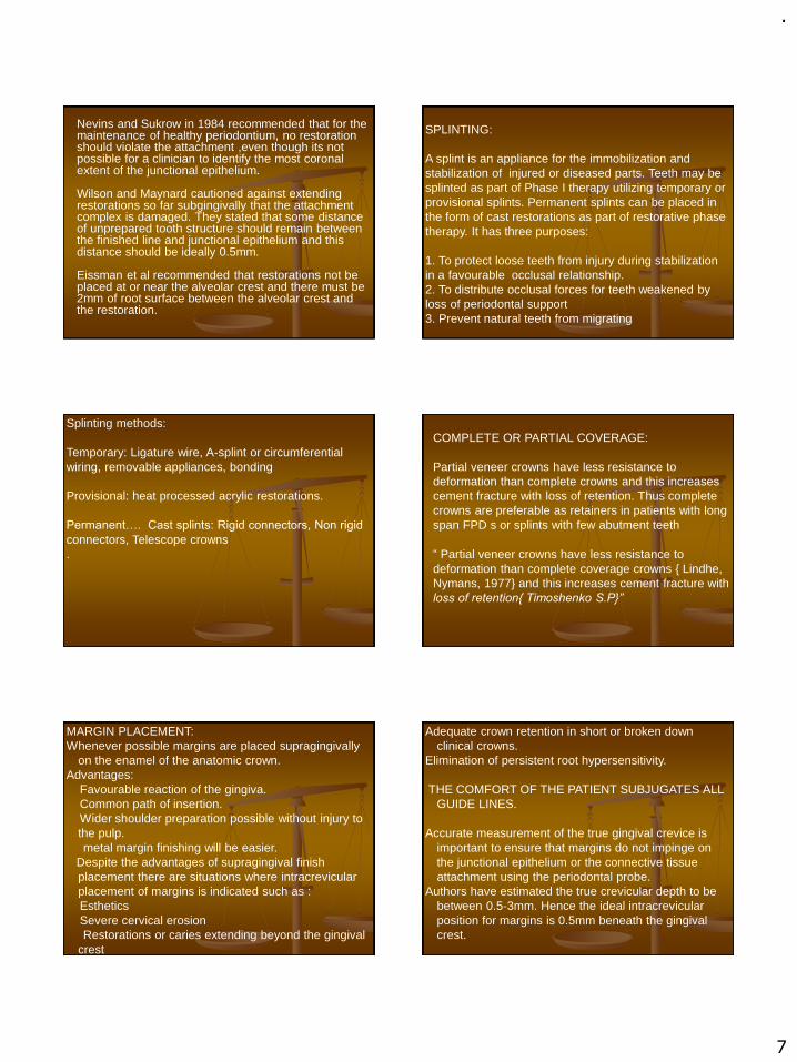
.
7
Nevins and Sukrow in 1984 recommended that for the maintenance of healthy periodontium, no restoration should violate the attachment ,even though its not possible for a clinician to identify the most coronal extent of the junctional epithelium.
Wilson and Maynard cautioned against extending restorations so far subgingivally that the attachment complex is damaged. They stated that some distance of unprepared tooth structure should remain between the finished line and junctional epithelium and this distance should be ideally 0.5mm.
Eissman et al recommended that restorations not be placed at or near the alveolar crest and there must be 2mm of root surface between the alveolar crest and the restoration.
SPLINTING:
A splint is an appliance for the immobilization and stabilization of injured or diseased parts. Teeth may be splinted as part of Phase I therapy utilizing temporary or provisional splints. Permanent splints can be placed in the form of cast restorations as part of restorative phase therapy. It has three purposes:
1. To protect loose teeth from injury during stabilization in a favourable occlusal relationship.2. To distribute occlusal forces for teeth weakened by loss of periodontal support 3. Prevent natural teeth from migrating
Splinting methods:
Temporary: Ligature wire, A-splint or circumferential wiring, removable appliances, bonding
Provisional: heat processed acrylic restorations.
Permanent…. Cast splints: Rigid connectors, Non rigid
connectors, Telescope crowns.
COMPLETE OR PARTIAL COVERAGE:
Partial veneer crowns have less resistance to deformation than complete crowns and this increases cement fracture with loss of retention. Thus complete crowns are preferable as retainers in patients with long span FPD s or splints with few abutment teeth
“ Partial veneer crowns have less resistance to deformation than complete coverage crowns { Lindhe, Nymans, 1977} and this increases cement fracture with loss of retention{ Timoshenko S.P}”
MARGIN PLACEMENT:Whenever possible margins are placed supragingivally
on the enamel of the anatomic crown.Advantages:
Favourable reaction of the gingiva.Common path of insertion.Wider shoulder preparation possible without injury to the pulp.metal margin finishing will be easier.
Despite the advantages of supragingival finish placement there are situations where intracrevicular placement of margins is indicated such as :EstheticsSevere cervical erosionRestorations or caries extending beyond the gingival
crest
Adequate crown retention in short or broken down clinical crowns.
Elimination of persistent root hypersensitivity.
THE COMFORT OF THE PATIENT SUBJUGATES ALL GUIDE LINES.
Accurate measurement of the true gingival crevice is important to ensure that margins do not impinge on the junctional epithelium or the connective tissue attachment using the periodontal probe.
Authors have estimated the true crevicular depth to be between 0.5-3mm. Hence the ideal intracrevicular position for margins is 0.5mm beneath the gingival crest.

.
8
In 1974 Guy M Newcombe studied the relationship between the location of the subgingival crown margins and gingival inflammation. He divided 50 patients and their controls into groups based on the distance of the crown margin from the base of the crevice(CM-CB)
Group I CM-CB-0.25 mmGroup II CM-CB-0.5mmGroup III CM-CB-0.75mmGroup IV CM-CB-1.0mm . From the study he concluded
that:- The difference in the mean plaque index,mean
gingival index and mean crevicular depth between crowned and control teeth was statistically significant.
- The nearer a subgingival margin approaches the base of gingival crevice the more likely it is that severe inflammation will occur
-The least inflammation is observed when subgingival crown margins are placed at the gingival crest or just into the gingival crevice.
GINGIVAL RETRACTION AND IMPRESSIONS:Impressions of intracrevicular finish lines may be
extremely injurious to the periodontium depending to a great extent on the quality and quantity of the attached gingiva and the type of retraction. All retraction methods induce transient trauma to the junctional epithelium and connective tissue of the gingival sulcus.
Methods for gingival retraction can be classified as:Mechanical – Copper band or tube Impression using
impression compound or elastomerChemicomechanical : Retraction cord with 8% racemic
epinephrine, alum or Phenylephrine hydrochlorideSurgical: Rotary curettage and Electrosurgery
Techniques of gingival retraction using retraction cords:Single cord technique.Double cord technique.Infusion technique of gingival displacement.Every other tooth technique

.
9
Ruel Jon in 1980 carried out histological study on humans by using retraction cord (Adrenaline) electrosurgery and copper band.
Copper band – give the most satisfactory results even with incisal wound, healed within 4 days.Retraction cord showed damage to sulcular and junctional epithelium and underlying connective tissue.Electrosurgery – showed annihilation of sulcular epithelium the healing was relatively slow (16-24 days) and gingival recession of 0.6mm.
THE EMBRASURES:
When teeth are in proximal contact, the spaces that widen out from the contact are known as embrasures. The interdental space is divisible into a facial and a lingualembrasure an occlusal or incisalembrasure that is coronal to the contact area and a gingival embrasure, which is the space between the contact area and the alveolar bone. The gingival embrasure is filled with soft tissue, but in periodontal disease spaces are created in the gingival embrasure.
THE GINGIVAL EMBRASURE:Embrasures arecritical considerations in restorative dentistry,Proximal surfaces of dental restorations are important because they create the embrasures essential for gingival health From the periodontal viewpoint, the gingival embrasure is the most significant. The proximal surfaces of crowns should taper away from the contact area facially, lingually,and apically.
◼Excessively broad proximal
contact areas and inadequate
contour in the cervical region
crowd out the facial and lingual
gingival papillae lead to gingival
inflammation and pocket
formation

.
10
CROWN CONTOURS:
The facial and lingual contours of restorations are also important in the preservation of gingival health. The most common error in recreating the contours of the tooth in dental restorations is overcontouring of the facial andlingual surfaces. In one study approximately 80 per cent of full gold crowns were wider than the tooth they were replacing, and all porcelain-bonded-to-metal crowns were too wide buccolingually. This overcontouring generally occurs in the gingival third of the crown and results in an area where oral hygiene procedures are unable to control plaque. Consequently, plaque accumulates and the gingiva becomes inflamed. Apparently undercontouring is not as damaging as overcontouring.
Yuodelis, Weaver and Sapkos in 1973 discussed the effect of facial and lingual contours af artificial complete crown restoration on the periodontium. In this classic article they went on to decimate the then widely held belief that overcontouring is permissible as it apparently deflected the food bolus from the marginal gingiva. They in fact opined that the cervical bulge overprotected the microbial plaque and that the flatter the contour was the lesser the plaque was retained. They concluded by saying that the final restoration should not follow the original anatomic crown but should recreate the original contours of the root portion. They advocated flattening of the cervical thirds and fluting of the furcation region for better accessibility for plaque control.
.In PFM atleast 1.5mm facial reduction is required.If the furcation has been exposed by periodontal surgery or by recession it is important that the restoration be contoured in such a way as to facilitate access for oral hygiene. In these cases it is necessary to emphasize the mid facial grove of the crown so that this groove is confluent with the furcation.
Labial contours in anterior teeth :THE EFFECT OF SURFACE FINISH OF RESTORATIVE MATERIALS ON THE PERIODONTIUM:The surface of restorations should be as smooth as possible to limit plaque accumulation. In the clinical situation porcelain, highly polished gold and highly polished resin all result in similar plaque accumulation
PONTICS
A pontic should meet the following requirements: it should (1) be aesthetically acceptable,(2) provide occlusal relationships that are favorable to the abutment teeth and opposing teethand the remainder of the dentition, (3) Restore the masticatory effectiveness of the tooth it replaces, (4) be designed to minimize accumulation of irritating dental plaque and food debris and to permit maximal access for cleansing by the patient, and (5) provide embrasures for the passage of food.
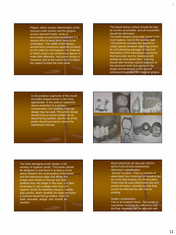
.
11
Plaque, which causes inflammation of the mucosa under pontics and the gingiva around abutment teeth, tends to accumulate around fixed prostheses if a special effort to keep them clean is not undertaken. The health of the tissues around fixed prostheses depends primarily on the patient's oral hygiene; the materials of which pontics are constructed appear tomake little difference, and pontic design is important only to the extent that it enables the patient to keep the area clean.
The tissue-facing surface should be kept as convex as possible, and all concavities should be eliminatedThe bullet-shaped spheroidal pontic is the most hygienic next to the sanitary type .The proximal surfaces are tapered to create spaces between adjoining pontics for self-cleansing passage of food and stimulation of the edentulous mucosa by food excursion and for cleansing with toothbrush and dental floss. Tapering should also recreate spaces adjacent to the abutment teeth that approach the shape and dimension of the natural embrasure to protect the marginal gingiva
In the posterior segments of the mouth, the bullet-shaped pontic is the most appropriate. In the anterior segments, where aesthetics is a primary consideration, the modified ridge-lap design may be used. This pontic design should have a convex surface on its tissue-facing surface, and the tip of the pontic should just barely contact the edentulous mucosa.
The least damaging pontic design is the sanitary or hygienic pontic. This pontic should be designed so that there is at least a 3-mm space between the undersurface of the pontic and the edentulous ridge; this allows the tongue and cheeks to remove any food particles that may lodge in this area. It is often necessary to use a design other than the hygienic pontic for aesthetic reasons. Saddle-type pontics, which straddle the ridge and have a concave tissue-facing surface, have the least desirable design and should be avoided
RESTORATION OF MOLAR TEETH WITH FURCATION INVASIONS:Glickman’s classification:
Normal furcation: There is no bone or attachment loss involving the furcation per se or the flute leading into the furcation. There may be early attachment loss and pocket formation coronally but the flute cannot be detected by with clinical probing .
Grade I Involvement:This is an incipient lesion. The pocket is suprabony involving the soft tissue and the flute concavity can be detected with the probe. There may be slight bone loss
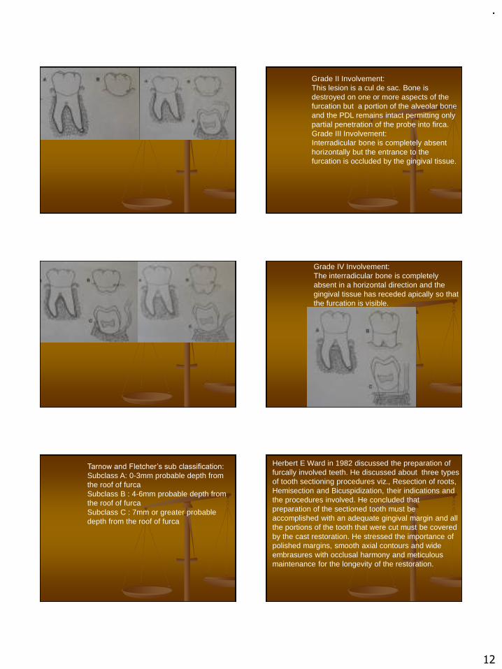
.
12
Grade II Involvement:This lesion is a cul de sac. Bone is destroyed on one or more aspects of the furcation but a portion of the alveolar bone and the PDL remains intact permitting only partial penetration of the probe into firca. Grade III Involvement:Interradicular bone is completely absent horizontally but the entrance to the furcation is occluded by the gingival tissue.
Grade IV Involvement:The interradicular bone is completely absent in a horizontal direction and the gingival tissue has receded apically so that the furcation is visible.
Tarnow and Fletcher’s sub classification:
Subclass A: 0-3mm probable depth from the roof of furcaSubclass B : 4-6mm probable depth from the roof of furcaSubclass C : 7mm or greater probable depth from the roof of furca
Herbert E Ward in 1982 discussed the preparation of furcally involved teeth. He discussed about three types of tooth sectioning procedures viz., Resection of roots, Hemisection and Bicuspidization, their indications and the procedures involved. He concluded that preparation of the sectioned tooth must be accomplished with an adequate gingival margin and all the portions of the tooth that were cut must be covered by the cast restoration. He stressed the importance of polished margins, smooth axial contours and wide embrasures with occlusal harmony and meticulous maintenance for the longevity of the restoration.

.
13
Root amputation: the removal of root from a multirooted toothRoot resection: surgical removal fo allor portion of root before or after endodontic treatmentHemisection : Surgical separation of a multirooted tooth through the furca in such a way that a root, or roots may be surgically removed along with the associated portion of crown.Splitting and retaining of roots: Bisection/ Trisection.
Diagnosis and treatment planning flow chart for teeth with resected roots
Condition of remaining teeth
Adequate supportfor fixed unit
Inadequate supportfor fixed unit
Plaque control measures
Scaling and root planning
Initial therapy evaluationVital root resectionduring periodontalSurgery.
Endodontics Endodontictherapy
Non vital root resectionDuring periodontalsurgery
Roots resected
Healing phase(4-6wks)
Dowel and core/amalgam plug
Over denture abutment
Endodontic therapy Completed in remainingroots(3-4 wks)
stabilisation
Healing phase(4-6wks)
Dowel and core resorstion
Final restoration

.
14
When treating patients the objectives of restorative therapy must be clear:-Preservation of teeth-Restoration of function-Comfort -EstheticsThe incorporation of all the above objectives may not be always possible. In such cases it is well to remember the fundamental precept of the health professionals:
“DO NO HARM”.
References:1.Tylman’s theory and practice of fixed prosthodontics:
W.F.P Malone, D.L. Koth, E. Cavazos, Jr, D.A Kaiser, S.M Morgano, 8th edition.2.Contemporary fixed prosthodontics: Rosenstiel, Land, Fujimoto, 3rd edition.3. Fundamentals of fixed prosthodontics: Herbert T. Shilingberg, Sumiya Hobo, Lowell D. Whitsett, Richard Joacobi, Susan E. Brackett, 3rd edition.4.Clinical periodontology: Carranza, Newman, 8th
edition.5.Textbook of clinical periodontology: Jan Lindhe, 2nd
edition.
6.Ruel J. et al: Effects of retraction procedure on periodontium of humans. J.Prosthet.Dent.1980 vol.44 pg.508-514.
7.Guy M. Newcomb: The relationship between thew
location of subgingival crown margins and gingival
inflammation. J Periodontol,1974pg.151-154
8.J. Gary Maynard, Richard Daniel, K. Wilson: Phisiologic dimensions of the periodontium siginficant to the restorative dentist. J Periodontol,1979 pg.170-1749. Ralph Yuodelis et al: Facial and lingual contours of artificial complete crown restorations and their effects on the periodontium. J Prosthet Dent, 1973,pg 61-6610. Herbert E. Ward: Preparation of furcally involved teeth. J.Prosthet Dent, 1982 pg 261-263
Thank you
.
1
RECENT ADVANCES IN FPD
Presenter :
Dr. GYAN PRAKASH
Contents
• Introduction
• Objective
• Recent advances in Diagnosis and treatment Planning
• Advances in Clinical Procedures
• Advances in Laboratory Procedures
• Conclusion
• References
INTRODUCTION
• The only thing in life that is constant is change, and development and the development is the essence of any change.
• Dentistry has come a long way from just replacing missing teeth to replacing lost alveolus supporting facial structures, recreating esthetics, reestablishing phonetics and many other major developments.
• Most of all we can say that in prosthetics by using all the artificialmaterials as well as technologies we can give a natural appearance of anindividual at the best of mankind.
Objective
• Using all the artificial materials as well as technologiesto give a natural appearance for an individual at the bestof mankind.
Advances in Diagnosis and Treatment Planning
Cone Beam Computed Tomography
• Traditional Medical CT – Fan shaped X-ray beam in helical progression.
Individual image slices of FOV acquired
Stacked by software to get a 3D view.
• CBCT - Pyramidal or cone shaped beam
Multiple 2D projections images ( Pri. Data) taken for FOV, in a single rotation sequence of gantry.
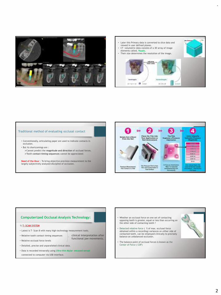
.
2
• Later this Primary data is converted to slice data and
viewed in user defined planes.
• CT volumetric data consists of a 3D array of image
elements called, Voxels.
• Their size determines the resolution of the image.
Traditional method of evaluating occlusal contact
• Conventionally, articulating paper are used to indicate contacts in
occlusion.
• But its shortcomings are :
➢Cannot predict the magnitude and direction of occlusal forces.
➢Tooth contact timing sequences cannot be appreciated.
Need of the Hour : To bring objective precision measurement to the
largely subjectively analysed discipline of occlusion.
Fuji film Prescale – Pressure Indicating Paper
Computerized Occlusal Analysis Technology:
1) T- SCAN SYSTEM
• Latest is T- Scan 8 with many high-technology measurement tools.
• Relative tooth contact timing sequences
• Relative occlusal force levels
• Detailed, precise and unparalleled clinical data.
• Data is recorded intraorally using Ultra-thin Mylar- encased sensor
connected to computer via USB interface.
clinical interpretation after
functional jaw movements.
• Whether an occlusal force on one set of contacting
opposing teeth is greater, equal or less than occurring on
the other side of contacting teeth ?
• Detected relative force ( % of max. occlusal force
obtained within a recording) variances on either side of
contacted teeth, can be employed clinically to precisely
balance an unbalanced occlusion.
• The balance point of occlusal forces is known as the
Center of Force ( COF)
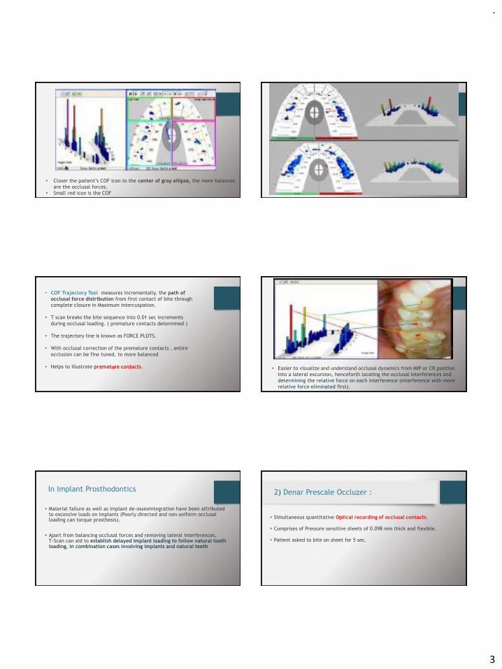
.
3
• Closer the patient’s COF icon to the center of gray ellipse, the more balances
are the occlusal forces.
• Small red icon is the COF
• COF Trajectory Tool measures incrementally, the path of
occlusal force distribution from first contact of bite through
complete closure in Maximum intercuspation.
• T scan breaks the bite sequence into 0.01 sec increments
during occlusal loading. ( premature contacts determined )
• The trajectory line is known as FORCE PLOTS.
• With occlusal correction of the premature contacts , entire
occlusion can be fine tuned, to more balanced
• Helps to illustrate premature contacts. • Easier to visualize and understand occlusal dynamics from MIP or CR position
into a lateral excursion, henceforth locating the occlusal interferences and
determining the relative force on each interference (interference with more
relative force eliminated first).
In Implant Prosthodontics
• Material failure as well as implant de-osseointegration have been attributed to excessive loads on implants (Poorly directed and non uniform occlusal loading can torque prosthesis).
• Apart from balancing occlusal forces and removing lateral interferences, T-Scan can aid to establish delayed implant loading to follow natural tooth loading, in combination cases involving implants and natural teeth
2) Denar Prescale Occluzer :
• Simultaneous quantitative Optical recording of occlusal contacts.
• Comprises of Pressure sensitive sheets of 0.098 mm thick and flexible.
• Patient asked to bite on sheet for 5 sec.
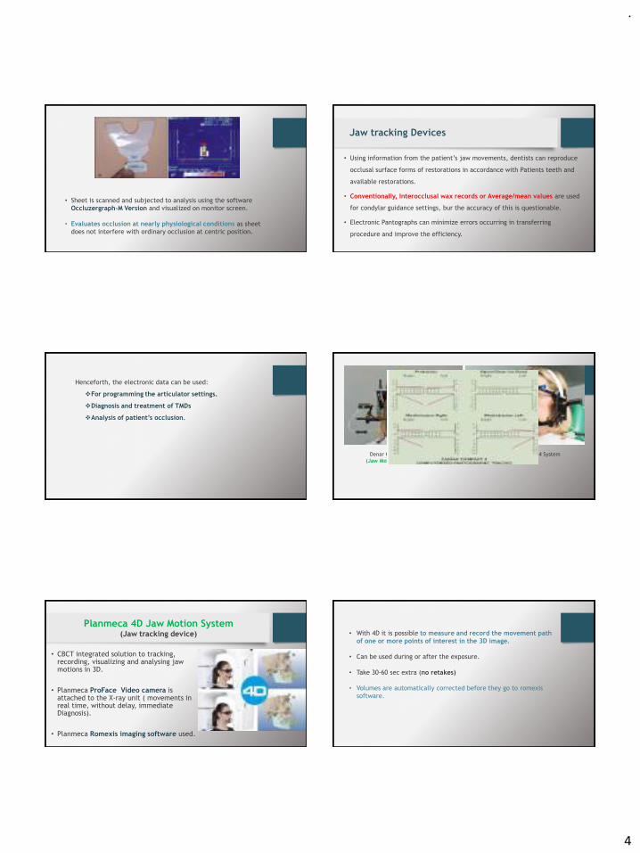
.
4
• Sheet is scanned and subjected to analysis using the software
Occluzergraph-M Version and visualized on monitor screen.
• Evaluates occlusion at nearly physiological conditions as sheet
does not interfere with ordinary occlusion at centric position.
Jaw tracking Devices
• Using information from the patient’s jaw movements, dentists can reproduce
occlusal surface forms of restorations in accordance with Patients teeth and
available restorations.
• Conventionally, Interocclusal wax records or Average/mean values are used
for condylar guidance settings, bur the accuracy of this is questionable.
• Electronic Pantographs can minimize errors occurring in transferring
procedure and improve the efficiency.
Henceforth, the electronic data can be used:
❖For programming the articulator settings.
❖Diagnosis and treatment of TMDs
❖Analysis of patient’s occlusion.
Denar Cardiax Compact
(Jaw Movement Analyzer)
Denar Cardiax 4 System
• CBCT integrated solution to tracking, recording, visualizing and analysing jaw motions in 3D.
• Planmeca ProFace Video camera is attached to the X-ray unit ( movements in real time, without delay, immediate Diagnosis).
• Planmeca Romexis imaging software used.
Planmeca 4D Jaw Motion System (Jaw tracking device) • With 4D it is possible to measure and record the movement path
of one or more points of interest in the 3D image.
• Can be used during or after the exposure.
• Take 30-60 sec extra (no retakes)
• Volumes are automatically corrected before they go to romexis
software.

.
5
Occlusal analysis
Advances In Clinical Procedures
Conventional Impression Materials :
• Reversible Hydrocolloids > Polysulphides > Polyethers > Silicones
( Mid 1930s : COM till 1960 ) (1950s) (1965) (1975)
• Drawbacks of Elastomeric Materials :
➢Effect of temperature and humidity.
➢Impression tray placed in mouth till the material setting.
➢Impression has to be poured with dental stone or plaster, to get a
working model, ( time taking).
Need of the Hour :
➢ To obtain virtual models for data record keeping,
➢ saving time
➢ Clinical evaluation in Real-Time
Digital Dental Impression Techniques
BASED ON DATA AQUISATION :
1. CEREC by Sirona System - Principle is “point and click” technology in which individual pictures of same object are stringed together..
2. Lava C.O.S by 3M ESPE - 3D In motion Technology, captures continuous 3D video images and displays in real time touch screen monitor
Ways the Acquired Digital Impression can be used :
1. CAD-CAM UNIT :
If the Scanning unit is a part of designing and milling unit , restoration fabricated
from blocks of ceramic and composite materials.
2. DEDICATED INTRAORAL SCANNER :
Scanned data sent to laboratories, where stereolithic or milled models/dies are
created using data, custom fabrication of restoration.
Eg, Cadent iTero and LAVA COS.

.
6
Advantages of a digital Impression
• Uncomfortable experience of making physical impression avoided.
• Tooth preparation can be checked and corrected in real time.
• Disinfection of Impression is not an issue.
• Data stored indefinitely, record keeping.
• Virtual models obtained.
Cordless Gingival Displacement Techniques
1. Expa-syl ( KERR)
2. Gingifoam : 3.Gingitrac :
4. MEROCEL 5. Stay-put

.
7
Gingival Troughing by Lasers :
• Diode and Pulsed Nd;Yag
• Less hemorrhage
• Faster and more effective healing
• Patient discomfort
• Broken needles
• Trismus
• Hematoma
• parasthesia
Conventional Local Anaesthetic Delivery
Need of the hour in Local Anaestic Delivery
• Anxiety-free and needleless comfort.
• No side effects or complications associated with use.
• Less hemorrhage, faster and more effective healing.
Nano-Robots for Local Anaesthesia
• By Richard Feymann
• It is a specialised nano machine.
• Interact with a specific cell by checking their surface antigen.
• They get power from metabolizing local glucose, oxygen and supplied acoustic energy.
• Typically 0.5-2 microns large with 1-10 nm parts made of
chemically inert forms of carbon, sensors, external
controller
• Colloidal suspension containing, millions of active analgesic
micron-size nano-robots, reach the pulp via gingival sulcus, lamina
propria and dentinal tubules.
• After reaching pulp they may be directed by the dentist to shut down
sensitivity of that particular tooth. Via Acoustic signalling.
• After the procedure, they are signalled to restore all sensations and
effuse themselves via usual human excretory channels.
Senn (GC America)
• New generation hybrid impression material, optimizes
best properties of polyether and vinyl poly siloxanes.
• Surfactant free, maximizes pickup , decreases luster
(improved viewing of detail).
• Maximizes hydrophilicity before set, excellent fluid
displacement, minimizing voids.
• Available in light body, heavy body, monophase and
putty consistency.

.
8
Visible light cured Polyether Urethane Di-methacrylate
• Introduced by Genesis and L.D Caulk.
• Transparent trays are used.
• 2 consistencies - light and heavy body.
• Both are simultaneous cured with a blue visible light curing
unit having > 8mm dia. Probe.
• Curing time – 3 min.
• Long working and short setting time
• Tear strength is 6000 to 7500 gm/cm2 ( highest among
elastomers).
• Can be electroformed.
Silginat ( Kettenbach LP )
• It is a medium viscosity poly vinyl siloxane with
alginate like consistency.
• Combines benefits of addition silicone and
alginates.
StatusBlue ( dmg America)
• Introduced as an alginate alternative.
• 100 % dust free.
• Siloxane material
3M ESPE DIRECTED FLOW IMPRESSION TRAY
• Made with CAD-CAM.
• Optimizes fit with only 3 sizes.
• Retention lips at borders are present which helps in decreasing material outflow.
• SELF RETENTIVE FLEECE STRIP WITH STRIATIONS.
• No adhesive needed + no tooth tray contact ( no occlusal flat spots )
• Flow defects and voids are avoided due to directed flow design.
Nano Coating Agent ( G-COAT PLUS )
• Used as final coating over esthetic restorations.
• Nano fillers are uniformly dispersed for high wear
resistance, preventing abrasion and discoloration.
• Used as final coating over jacket crowns, veneers,
provisional restorations, composite restorations and light
cured with LED or halogen lights.
• Smooth high luster finish retained over time.
NTI Guide Pins Diamonds ( Kerr rotary )
❖ Uncoated guide pin used as Horizontal Diatance
keeper.
• Controlled preparation.
• Well defined and uniform cutting depth even when
vision is obstructed.
❖ Pin used as Vertical Distance keeper.
• 0.5mm guide pin assures a predefined distance to the
periodontium.
• Violation of the biological width largely avoided.

.
9
Hybrid Air-Electric Handpiece
• Adaptive torque control ( ATC).
• Has a sensor in the hand piece which operates a valve
( continuously regulates the amount of air pressure to
turbine).
• As soon as the bur contacts the tooth, instead of losing
power and slowing, the valve opens and sends more
pressure to turbine (compensation).
• Has power of electric hand piece but size and weight
characteristics of air driven hand piece.
ProDrive System Handpieces
Dual Instrumentation ( Great white Ultra System )
• Lusting described utilization of diamond and carbide burs
of same size and configuration.
• Diamond for bulk reduction and tungsten carbide for
producing smooth finish lines + precise internal features
( grooves, boxes).
• Diamond burs, leave undesirable rough surfaces and
irregular cavosurface finish lines.
Automatic/ Robotic Crown Preparation
• A robotic device with a 3 D motion planning software
was developed , which controlled an Ultra-Short pulse
laser ( USPL) beam to complete tooth preparation
process on 15 extracted human intact first molars.
• Target preparation shapes of the molars was installed in
the CAD software.
Ref :“ Am automatic tooth preparation technique : a preliminary study” Yuan F, Wang Y et al. ; Apr 2016 issue, Nature Publishing Group
Results : Time taken was 17 min, average shape error of 0.05-0.17 mm ,
convergence angle error of 1 degrees.
Manual Shade Matching
➢Retinal fatigue
➢Background effects ( ambient colors )
➢Metamerism ( lightning ).
➢Color blindness
➢Brunescence ( natural browning of cornea , age factor )
Perception varies
A)Spectrophotometers-It measures and records the amount of visible radiant energy reflected or transmitted by an object one wavelength at a time for each i.e. Hue, value and chroma, present in the entire visible spectrum.
Technological shade systems

.
10
B) Colorimeteres
• Colorimeters provide measurements in
CIELAB units (L*, A*, B*) that can
compare the color parameters of
different objects when analyzed
mathematically.
Microcolor colorimeter (a photoelectric tri-stimulus colorimeter) is a
self-contained measuring system that requires no external power
source
Filter Colorimeter (A silicon photodiode array requiring both an external
power source and a standard light source); has spectral correction filters
limiting the spectral characteristic of light reaching detector surface.
Inadequate sensitivity for low light levels, absolute accuracy inferior to
spectrophotometer.
S h a d e e y e N C C b y S h o f u
• Acquire RED, GREEN, BLUE image information to
create a color image. They do not control key
variables associated with accurate color
determination.
• SHADE SCAN from Cynovad creates an image of the
tooth with a translucency and characterization
map, and then will generate a printed report.
• Provides the technician with a detailed image of
the tooth surface as well as useful color mapping.
C) RGB Devices Digital Cameras
• Instead of focusing light upon film to create a Chemical
Reaction, they capture images using CCDs ( containing
millions of light sensitive elements k/a Photosites )
• Factors such as illumination and the angle of the
photograph will alter how color is perceived by the
camera, therefore appropriate calibration protocols to
be applied.
• To get full color image , most sensors use filtering to look at the light
in 3 primary colors ( all 3 received by same sensor) similar as filter
colorimeter.
• Highest quality sensors use 3 separate sensors with different and
seperate color filter over it.
CEREC
Chairside Economical Restoration of Esthetic Ceramics, or Ceramic Reconstruction System
• Same day ceramic restoration.
• Has gained acceptance when used with recently developed adhesive composite luting materials.
• Inlays, onlays, crowns, FPD frameworks can be fabricated in clinical settings.
• Time intensive occlusion adjustments not required.
• Success rate is 95.5 % following 9 years and 88.7 % after 17 years.
“ long term clinical results of chairside Cerec CAD/CAM inlays and onlays “ Int J Prosthodont 2008 Jan-Feb; 21 (1) : Pg- 53-9

.
11
Recent Advances in Laboratory Procedures
LABORATORY PROCEDURE
CAD-CAM
ADDITIVE MANUFACTURING
Inkjet based System
Selective Laser Sintering
Fused Deposition Modeling
Steriolithography
SUBSTRACTIVE MANUFACTURING
VIRTUAL ARTICULATOR
Dr. Duret, first to make an optical impression of abutment tooth, and
made crown using numerically controlled milling machine. Gave Sopha
System.
Dr. Moermann, CEREC System- used technology chairside, use of intraoral
camera and milling of ceramic inlays, same day delivery.
Dr. Andersson, Procera System- Ti copings by spark erosion , CAD-CAM for
composite veneered restorations. Later this was a networked production
system using satellite digitizers.
Components of CAD-CAM
Geometry Digital Data
Data set for that Product
Desired product
Digitization tool/
Scanner Application Software
Production
Technology
Possible Sequence for Manufacturing The Digitization Process
• Most CAD-CAM Systems use stone models as heir starting point.
• Surface of stone model measured using tools to obtain digital data, using a variety of Methods :
1. Contact Probe ( eg. Procera )
2. Laser Displacement Gauge( Eg. CEREC InLab )
3. Optical Scanner ( Eg. CEREC OmniCam )

.
12
CAD ( Computer Aided Designing ) Process
• Digital 3D data obtained can only be read by a specialized dental design
software.
• Analysis and designing is carried out in digital environment according to
established prosthodontic principles using CAD software.
• Software now generates an STL file which can be stored in various data
formats ( specific for that particular manufacture).Software can be used to design copings and bridge frameworks, crowns and
fridges, inlays/onlays and veneers, customised implant abutments, implant
bridges and bars, surgical Implant placement guides and provides virtual
diagnostic wax ups.
CAM – Subtractive Manufacturing
• The Construction data by software is converted to milling strips and is loaded
into milling device.
• Processing devices are distinguished by the number of milling axes :
• 3 Axis Devices : Mill path points are uniquely defined by the X-, Y-, and Z-
values.
➢ Minimal Calculation investment.
➢ Milling of subsections, axis diversions
and convergences not possible.
➢ Eg. InLab (Sirona), LAVA ( 3M ESPE ),
• 4 Axis Devices :
➢Along with the 3D special movement , tension bridge can be turned
infinitely variabily ( 4th axis ).
➢Material and milling time saved.
➢Eg. Zeno ( Wieland-Imes ).
• 5 Axis Device :
➢ In addition to above there is possibility of rotating the milling spindle
( 5th Axis ).
➢Enables milling complex geometries eg. FPDs with converging abutment
teeth and with converging areas in the exterior of frame. Eg. Everest
Engine by KaVo
Limitations of Subtractive Manufacturing
• Precision fir of the inner contour of restoration depends on the size of smallest
usable milling tool, if the diameter of tool is larger than the part of the
restoration, can lead to decreased precision fir or inferior marginal properties.
• Unused raw material wasted. Recycling of excess ceramic material is not
feasible.
• Due to heavy abrasion and wear, milling tools withstand only short running cycles.
• Microscopic cracks in ceramic during machining.
Additive Manufacturing / Rapid Prototyping
• Took off in late 80s as it allowed to engineers to make prototypes of their parts quickly and easily from a CAD file and since 20 years most people who use additive manufacturing In technical field Refer it as rapid prototyping.
• Has 2 phases
• Virtual Phase ( modelling and simulating ) and
• Physical Phase ( fabrication ).
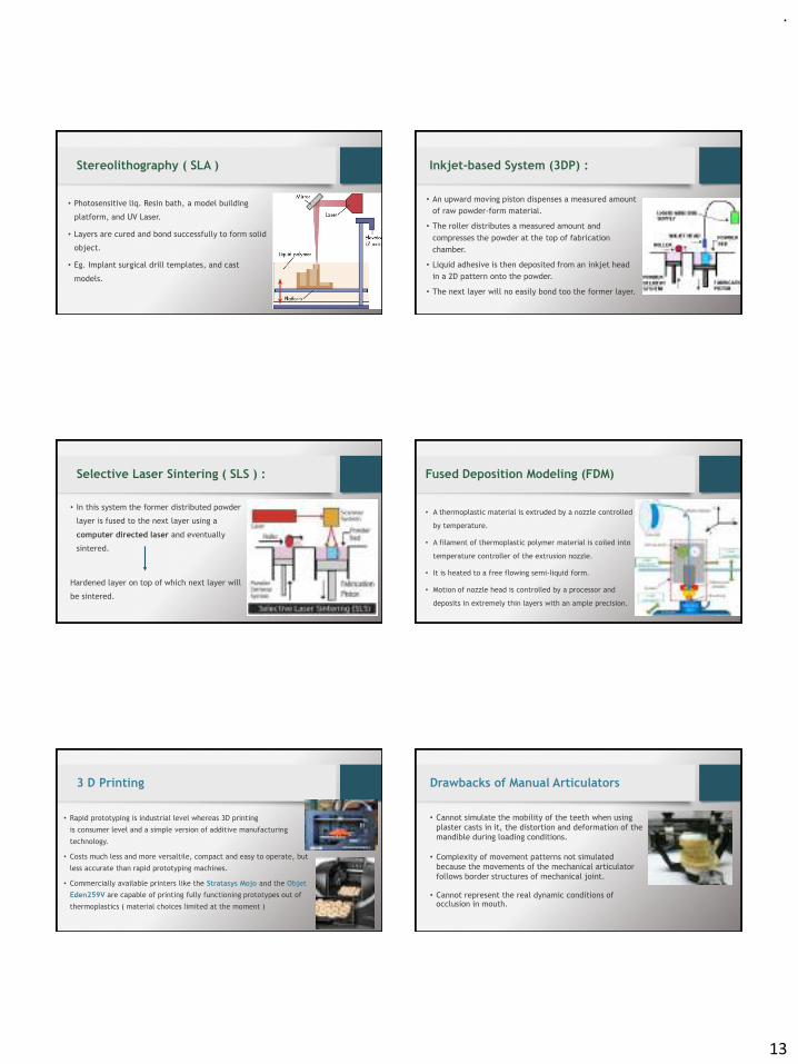
.
13
Stereolithography ( SLA )
• Photosensitive liq. Resin bath, a model building
platform, and UV Laser.
• Layers are cured and bond successfully to form solid
object.
• Eg. Implant surgical drill templates, and cast
models.
Inkjet-based System (3DP) :
• An upward moving piston dispenses a measured amount
of raw powder-form material.
• The roller distributes a measured amount and
compresses the powder at the top of fabrication
chamber.
• Liquid adhesive is then deposited from an inkjet head
in a 2D pattern onto the powder.
• The next layer will no easily bond too the former layer.
Selective Laser Sintering ( SLS ) :
• In this system the former distributed powder
layer is fused to the next layer using a
computer directed laser and eventually
sintered.
Hardened layer on top of which next layer will
be sintered.
Fused Deposition Modeling (FDM)
• A thermoplastic material is extruded by a nozzle controlled
by temperature.
• A filament of thermoplastic polymer material is coiled into
temperature controller of the extrusion nozzle.
• It is heated to a free flowing semi-liquid form.
• Motion of nozzle head is controlled by a processor and
deposits in extremely thin layers with an ample precision.
3 D Printing
• Rapid prototyping is industrial level whereas 3D printing
is consumer level and a simple version of additive manufacturing
technology.
• Costs much less and more versaltile, compact and easy to operate, but
less accurate than rapid prototyping machines.
• Commercially available printers like the Stratasys Mojo and the Objet
Eden259V are capable of printing fully functioning prototypes out of
thermoplastics ( material choices limited at the moment )
Drawbacks of Manual Articulators
• Cannot simulate the mobility of the teeth when using
plaster casts in it, the distortion and deformation of the
mandible during loading conditions.
• Complexity of movement patterns not simulated
because the movements of the mechanical articulator
follows border structures of mechanical joint.
• Cannot represent the real dynamic conditions of occlusion in mouth.

.
14
Virtual / Software Articulators
• Exist as computer program. Have virtual condylar and
incisal guide planes.
• Guide planes measured precisely using jaw motion analyser.
• Capable of simulating human mandibular movement by
moving digitalized occlusal surfaces against each other
smooth and collision free and correcting the occlusal
surfaces if necessary.
Types
1. Completely Adjustable:
• Records exact movement path of mandible
using jaw motion analyser.
• A special sensor determines reference planes.
• Digitized dental arches now move along these
movement paths, the software visualises the
static and kinematic occlusal collisions and
does the occlusal designing and correction in
CAD System.
• Eg. DentCAM
2. Mathematically simulated:
• Fully adjustable 3D virtual articulator reproducing
the mathematical simulated movements of a
mechanical articulator.
• More versatile than mechanical device eg. Curved
Bennett and other movements. Eg. Stratos 200
Recent Materials for chairside CAD-CAM
• CEREC AC ( Sirona Dental ) and E4D ( D4D technology ) systems
predominantly utilize :
• Feldspathic porcelain ( Vita Mark 2 by Vident, Sirona Blocs )
• Leucite reinforced porcelain ( Empress Cad by Ivoclar )
• Lithium di silicate porcelain ( emax CAD by Ivoclar )
• Composite resins ( Paradigm MZ100 by 3M ESPE )
Reconsidering perception about Composite resin blocs ?
• Composite blocs not use as frequently as ceramic material.
• General perception of dentists that composites are not as strong as
ceramics and therefore not to use for rehabilitating posterior occlusion.
• Randomized control trial results :
• After 10 years of clinical function, no significant difference in margin
finish, proximal contact and anatomic form.
• Six porcelain inlays fractured during the course of study, while only one
fracture of composite inlay reported.
Reference: “ Efficacy of composite versus ceramic inlays and onlays “ Chabouis HF, Prot C et al. : Trials, BioMed Central
Nano Ceramics ( Lava Ultimate by 3M ESPE )
• Monolithic esthetic block form for chairside and laboratory CAD-CAM.
• Agglomerated zirconia/silica clusters ( 20nm silica and 4-11 nm Zr.)
• Non agglomerated 20 nm silica + 4- 11 nm Zr with 80 % ceramic load.
• Flexural Str – 200 Mpa ( more than feldspathic and leucite reinforced )
• Less brittle than feldspathic glass ceramic ,
• Retains high gloss surface over time.
.
15
Conclusion
• Computer graphics and CAD-CAM have revolutionized the field of
prosthodontics as it is now possible to provide equivalent of cast restoration
in single appointment.
• Advances in the field of fixed prosthodontics gives hand full of newer
products and techniques for the dentists.
• More research and clinical studies should be conducted using the recent
developments, and incorporating them in our clinical practices should be
encouraged.
References
1. Mantri SS, Bhasin AS, CAD/CAM in dental restorations: an overview . J. of
Annals and Essences of Dentistry 2010; 2(3) : 123-128.
2. Efficacy of composite versus ceramic inlays and onlays “ Chabouis HF, Prot C
et al. : Trials, BioMed Central.
3. long term clinical results of chairside Cerec CAD/CAM inlays and onlays , Int J
Prosthodont 2008 Jan-Feb; 21 (1) : Pg- 53-9.
4. Agbaje JO, Casteele EV et al. Assessment of occlusion with T Scan system in
patients undergoing orthognathic surgery, July 13 2017,; Scientific reports,
Nature Publishing Group.
5. Smitha AJ, Savitha PN Shade matching in esthetic dentistry – from past to
recent Advances; J Dent Care Med 2017 3(1): 102.
6. Thomas B, Mathew CA, Muthuvignesh j Nanotechnology- Applications in
Prosthodntics : A Literature Review. J Orofac Res 2014;4(2) : 103-10.
7. Kurtzman GM, spinninf down the tooth : Advances in Crown Preperation,
Compendium May 2014 ; 35(5)
8. Kim Li RW, Matinlinna JP, Ceramic dental Biomaterials and CAD/CAM
technology : state of art, J. Prosth Research , Oct 2014; 58(4): Pg- 208-16.
9. Tam WK, Lee HJ Dental shade matching using a digital camera, J. of
Dentistry ;40(2) 2012: pg- 3-10.
Thank You
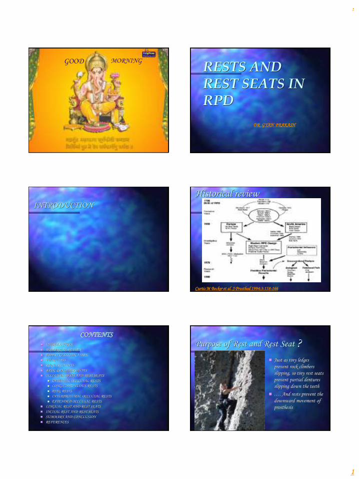
.
1
GOOD MORNING
RESTS AND REST SEATS IN RPD
DR GYAN PRAKASH
INTRODUCTION
Historical review
Curtis M Becker et al .J Prosthod 1994;3:158-166
CONTENTS
◼ INTRODUCTION
◼ HISTORICAL REVIEW
◼ TYPES / CLASSIFICATION
◼ FUNCTIONS
◼ REQUIREMENTS
◼ BASIC CONSIDERATIONS
◼ OCCLUSAL RESTS AND REST SEATS
◼ INTERNAL OCCLUSAL RESTS
◼ LONG/CONTINUOUS RESTS
◼ RING RESTS
◼ INTERPROXIMAL OCCLUSAL RESTS
◼ EXTENDED OCCLUSAL RESTS
◼ LINGUAL REST AND REST SEATS
◼ INCISAL REST AND REST SEATS
◼ SUMMARY AND CONCLUSION
◼ REFERENCES
Purpose of Rest and Rest Seat
◼ Just as tiny ledges
prevent rock climbers
slipping, so tiny rest seats
prevent partial dentures
slipping down the teeth
◼ …. And rests prevent the
downward movement of
prosthesis
?

.
2
DEFINITION
According to glossary of Prosthodontic terms(8) -
1. Rest - is a projection or attachment, usually on the side of
an object .
2. Rest seat - is the prepared recess in a tooth or restoration
created to receive the occlusal, incisal, cingulum or lingual
rest.
According to McCracken’s -
1. Rest - Any unit of a partial denture that rests on a
tooth surface to provide vertical support.
2. Rest seat - The prepared surface of an abutment to
receive the rest
According to Ernest L. Miller -
1. Rest - is a projection of the clasp which lies in a prepared
recess of the abutment tooth and acts to support and
stabilize the removable partial denture
2. Rest seat - The prepared recess in a tooth created to
receive the occlusal, incisal or lingual rest.
◼ Russell states that rest is a rigid extension of a partial
denture that contacts the remaining tooth structure to
dissipate functional forces.
According to Grant A.A. and Johnson W. a rest is an
extension from partial denture which is positioned on the
surface of a standing tooth capable of providing resistance
to displacement of the denture in tissueward direction.
Kratochvil stated that rest must be positive and should not
allow the prosthesis to slide off the tooth. They must provide
a positive connection between prosthesis and tooth.
CLASSIFICATION/TYPES
According to McCracken, on the basis of tooth surface
prepared to receive them:
Occlusal
Cingulum
Incisal
Lingual

.
3
According to Stewart,on the basis of function they serve :
Primary rests/ Principle rests
Secondary or auxiliary rests
According to Kratochvil, on the basis of their location in the
arch, rests can be :
Anterior rests
Posterior rests
FUNCTIONS OF THE RESTS
The primary purpose of the rest is to provide vertical
support for the partial denture and thus resist the
movement in a cervical direction .
❖ -maintains components in
their planned positions
- Provide reciprocation
and stabilization.
❖Directs and distributes occlusal loads to the
abutment teeth and directs forces in the long
axis of the teeth
Kratochvil FJ: J Prosthet Dent 38:3,1977
❖ It transmits vertical load as well as the horizontal
forces to the tooth.
Provide rigid prosthetic support.
❖ Maintains established occlusal relationships by
preventing settling of the denture.
◼ Prevent supra eruption.
◼ Restore occlusion.
Kratochvil FJ:Partial Removable Prosthodontics;Saunders Co. : p-18-21
◼ Deflection of food by bridging the gap
between two teeth
A.A.Grant/W.johnson:Removable Denture Prosthodontics; Churchill
Livingstone, p:110-111
.
4
◼ Prevents impingement of soft tissues.
◼ Protects the denture/abutment tooth junction.
◼ Restore anterior guidance- anterior rests.
◼ Restores anterior anatomy as required.
◼ Provides positive seat by extending over the
incisal edge.
Kratochvil FJ:Partial Removable Prosthodontics;Saunders Co. : p-17
◼ Splints mobile
teeth.
BASIC CONSIDERATIONS FOR RESTS AND REST SEATS
◼ Rests should be sturdy
placed in properly
engineered recesses, in the
surfaces of the teeth.
◼ The rest seat should be
prepared within the confines
of the greatest tooth mass-
more PDL fibers.
◼ Vertical stress will be
resisted by all of the fibers.
◼ Floor of rest seat
1. Floor of the recess should be
less than 90° to the long axis
of the tooth- to direct stresses
axially.
2. Apical to the marginal ridge.
McCracken’s Removable Partial Denture eighth edition p-47

.
5
◼ Positioned in line with
the residual ridge.
◼ Anterior rests should
be as close to the
center of the tooth as
possible.
Rounded in all aspects (no
sharp line angles).
Minimal preparation in
dentin.
◼ Anterior positioning of the rest and the rotation axis to favor biomechanics:
1. Forward and downward
movement, disengagement
of DR.
2. More vertical direction of
forces.
3. More advantageous vertical
support from denture base
area.
◼ Placed as close to the
gingiva and bone as
possible to reduce
leverage.

.
6
◼ Placement of rest on tooth
surface away from
edentulous area-
Tipping force in opposite direction
Maintain contact with adjacent
teeth results :
1) multiple tooth support
2) favorable direction of force
Basic requirements of rests and rest seats
Provides rigid support.
Extends to center of the tooth in tooth supported
situations.
Rounded, with no sharp angles (for ease of cleaning,
making impressions, prevent tooth fracture).
No undercuts in the path of insertion.
Minimum of 1 mm thick.(depending on type of material )
Restores the occlusal plane.
Provides reciprocation.
OCCLUSAL REST AND REST SEAT
Outline form
◼ Rounded triangle with the base resting on the
marginal ridge and apex toward the center of the
occlusal surface.
◼ Dimensions- ½ the buccolingual width from cusp
tip to cusp tip and 1/3 to ½ the mesiodistal width.
Is as long as it is wide, should be at least 2.5 mm
for both molars and premolars.
Reduction of the marginal ridge of
approximately 1.5 mm is usually
necessary.
Junction of occlusal rest to the abutment
should be shallow ball and socket joint in
distal extension cases.
The floor of the occlusal rest seat should
be apical to the marginal ridge and the
occlusal surface.
- Can be concave, or spoon shaped- for
distal extension.
- Can be box shaped- for tooth supported.

.
7
Rest seats not prepared opposing functional cusps.
Minimum metal thickness is 0.5mm at thinnest
point and 1-1.5mm at marginal ridge.
Proximo-occlusal line angle of the preparation
should not be sharp.
Basic rules for placement of occlusal rests
1) If there is a weak
abutment……….
2) If both teeth are
weak……strategically
distribute…….
Never place a rest where it
interferes with a natural occlusal
stop………..
Preparation of occlusal rest.
◼ Armamentarium for rest preparation
◼ Preparation in enamel
Rest seat preparations in sound enamel.Preparation of occlusal rest seats always must follow proximal
preparation, never precede it.
Occlusal rest seats in sound enamel may be prepared with diamond points of approximately the size of nos. 6 and 8 round burs or with carbide burs.
Occlusal rest seat prep. in existing restoration.
It is same as in enamel. Proximal preparation first and then rest seat
should be placed.
Rest seat preparation in amalgam should be avoided because of creep.
Though some compromise is permissible, the basic principles of rest
seat preparation should not be violated. When perforation occurs it
may be filled with gold foil.
.
8
Occlusal rest seats in crown/inlays/onlays.
- Most ideal way of getting positive support.
- Indicated in - rotated/inclined tooth.
- mandibular bicuspid with rudimentary cusp.
- abraded tooth.
- These are generally made larger and deeper than the enamel.
- Those made in abutment crowns supporting tooth borne dentures maybe slightly
deeper than those in abutments supporting a distal extension base.
Types of occlusal rests.
Internal Occlusal rests
◼ A totally tooth supported partial denture may
use internal occlusal rests for tooth occlusal
support and horizontal stabilization.
◼ An internal occlusal rest is not an internal
attachment .
Advantage:
✓ Facilitates the elimination of visible clasp arm buccally
✓ Permits the location of the rest seat in a more favorable position in
relation to the “tipping” axis of the abutment. Retention provided by
lingual clasp arm lying in a natural or prepared infrabulge area on the
abutment tooth.
◼ A) provides minor resistance to horizontal movements
◼ B)provides moerate load transfer
◼ C)provides maximum load transfer
Long Or Continuous Rests
Splinting periodontally weakened teeth
◼ The long or continuous rest can serve
as an effective stabilizing or unifying
device.
◼ When occlusal force is delivered in one
area, all the remaining teeth act in
unison to provide support. With
planning, this type of rest can restore
the occlusal plane, provide support,
and splint the arch.
Control position of unopposed teeth
◼ Many times a situation exists in which a
tooth has lost its antagonist in the opposing
arch but does not need a replacement for
masticating functions. Extending the rest in
the partial denture planning and design not
only gains support from that tooth but also
holds it in position, preventing elongation
and eliminating the necessity of a second
prosthesis in the opposing arch.

.
9
Ring rests are usually best for isolated
teeth provided there is sufficient area of
tooth above the survey line to
accommodate them.
An additional advantage of ring rests is
that they provide a better distribution of
load to the abutment.
Ring Rests
Occlusal rests on isolated posterior teeth present a problem. Many of
these teeth are in firm occlusion with their opponents and any modification
of their occlusal surfaces allows them to change position either by tilting or
by erupting further
A Roy MacGregor/David M Watt: Designing Partial Dentures;Wright Co. P-209
Inter Proximal Occlusal Rests ( embrasure rest)
The design of a direct retainer
assembly may require that
interproximal occlusal rests be
used.
Interproximal occlusal rest seats
are prepared as individual
adjoining occlusal rest seats.
Preparations must be extended
farther lingually.
The lingual interproximal area
requires only minor preparation.
Adjacent rests rather than a single rest are
used to
- Avoid inter proximal wedging by the
framework.
- Also to shunt the food away from
contact points.
Care must be exercised to avoid
eliminating contact point of abutment
teeth.
Sufficient tooth structure must be
removed to allow for adequate bulk of the
component to be so shaped that occlusion
will not be altered.
EXTENDED OCCLUSAL REST
Indicated - in Kennedy class II, modification 1 and Kennedy class III situations
when the most posterior abutment is a mesially tipped molar
1. Minimize further tipping of the abutment \ forces are directed down the
long axis of the abutment.
2. This rest should extend more than one-half the mesiodistal width of the
tooth, be approximately one-third the buccolingual width of the tooth.
◼ If abutment is severely
tilted the extended
occlusal rest may be in
the form of an onlay.
Anterior rests
LINGUAL RESTS(Cingulum rests)
◼ Anterior teeth may be used to support an
indirect retainer or auxiliary rest.
◼ When a canine is not present, multiple rests that
are spread over several incisor teeth are
preferable to the use of a single incisor.
◼ Lingual rest should be kept near the center of
rotation.

.
10
Preferable to an incisal rest
- It is placed nearer the horizontal axis of rotation (tipping
axis) of the abutment , less tendency to tip the tooth.
- More esthetically acceptable.
A lingual rest may sometimes be placed in an enamel seat at
the cingulum or just incisally to the cingulum.
Outline form
A slightly rounded V(half moon shaped) is
prepared on the lingual surface at the
junction of the gingival and the middle -one
third of the tooth. The apex of the V is
directed incisally.
prep. Is broadest at lingual aspect..
Dimensions – mesiodistal width = 2.5-3mm,
labiolingual width = 2mm,
incisoapical depth = 1.5mm
Preparation
◼ Preparation may be started by using an
inverted cone-shaped diamond stone and
progressing to smaller, tapered stones with
round ends to complete the preparation.
◼ All line angles must be eliminated, and the
rest seat must be prepared within the enamel
and must be highly polished.
◼ A predetermined path of placement for
the denture must be kept in mind in
preparing the rest seat.
Method of obtaining support
In a cast restoration
Plan and execute a rest seat in the wax pattern
Contour of the framework restores the lingual formof the tooth.
Cast Co-Cr rest seats attached to lingual surface ofanterior teeth
Composite may be added to lingual surface
J Prosthet Dent.,1988;60(1) :127
J Prosthet Dent.,1987;58:458-462
Inlay with pins
Crowns / onlays

.
11
Recent advances in cingulum/lingual rests
◼ The use of ceramic orthodontic brackets is an alternative method of preparing a rest seat on the lingual surface of lower canine teeth. These brackets are bonded with either a no-mix or a two part adhesive system and shaped into rest seats using diamond burs.
◼ The advantage over metal acid etched retained rests is that a time consuming lab step is reduced. The other adv. Over conventional composite build ups is that of higher bond strength.
Amy L Counts and Aubrey Hopkins: J Prosthod 1995;4:3-5
INCISAL RESTS AND REST SEATS
Less desirable - more unfavorable
leverage than lingual rest - orthodontic
movement of the tooth
Incisal rests are placed on prepared rest
seats at the incisal angles of anterior
teeth
Used predominantly as auxiliary rests or
as indirect retainers.
May be used on a canine abutment in
either arch, but more commonly on the
mandibular canine.
Provides definite support , relatively little
loss of tooth structure and little display
of metal.
Outline form
Small ‘V’- shaped rounded notch is prepared at the incisal
angle of a canine or on the incisal edge of an incisor, with the
deepest portion of the preparation apical to the incisal edge.
Dimensions - 2.5 mm wide and 1.5 mm deep.
The notch is beveled both labially and lingually, and the
lingual enamel is shaped to accommodate the rigid minor
connector connecting the rest to the framework.
The floor of rest seat is extended slightly onto the labial
aspect of tooth.(to provide bracing effect)
Various forms of incisal rests
Incisal rest is placed either at mesioincisal or distoincisal angle.
It can be incorporated into a lingual plate – for additional stabilization.
Multiple incisal rests can be placed for additional support.

.
12
Indications Trouble shooting ill-fitting rests
◼ Occlusal rests must fit their respective rest seats on
the abutment teeth with precision if they are to
perform their functions.
◼ Poor impression, duplicating technique causes
castings not to fit.
Location of interfering part
◼ The under site of the rest seat is sandblasted to give
it a stain finish……….
◼ Carbon is deposited on under side of the rest…
◼ In some instance rest does not contact its rest seat at all.
◼ The rest may be refitted by burnishing a small piece of 0.001 platinum foil to the rest seat in the tooth.
◼ The denture is then seated and the platinum foil is sealed to the rest..
◼ Denture is invested burned out and solder is deposited in its place.
COMPLICATIONS
◼ Dentinal exposure leading to hypersensitivity and caries.
◼ If not planned properly it can lead to damage to periodontium.
◼ In individuals with high caries index it can lead to caries.
◼ If rest seat is not of adequate depth it can lead to fracture of rest.
Review of literature
◼ Bert T. Cecooni (1974) conducted a study to determine which type of rest transmits force to the abutment teeth in most favourable manner.
◼ Two types of partial denture rest were used
◼ Precision attachment
◼ Deep rest
◼ He also studied the effect of bilateral loading and unilateral loading on abutment tooth movement.
◼ He concluded that precision rest and deep rest, effect tooth movement in a similar manner.
◼ Bilateral loading of a RPD causes significantly less abutment tooth movement then does unilateral loading.
◼ Ronald E. Myers et al (1986) conducted a study on 4 different rest seat configuration, ◼ Mesial
◼ Distal
◼ Mesial and distal
◼ Continuous rest
◼ 4 rests with relieved and unrelieved guide plates were evaluated for optimum stress distribution around the root.
◼ The finding demonstrate that ◼ Continuous rest had most favourable stress concentration
distribution.
◼ All other rest designs demonstrate more lateral stress than continuous rest.
◼ Relieved guide plates demonstrated 58% less maximum shear stress in the apical portion than unrelieved guide plates.

.
13
◼ Byron P. Sansom et al (1987) conducted a study
on rest seat design for inclined posture abutment.
◼ Mesial rest only
◼ Distal rest only
◼ Mesial and distal rest
◼ Lingual groove rest
◼ A long channel type occlusal rest
◼ Concluded that mesial rest on inclined molar
abutment demonstrated maximum tipping force and
channel rest on inclined molar abutment demonstrate
least amount of tipping force.
Bradley .G.Seto;Angelo.A.Caputo(1987) conducted a study on Bond strength of etched metal resin bonded cingulum rest seats.
◼ They concluded that the dislodgement load of custom fabricated etched metal resin-bonded cingulum rest seats appears to be substantially greater than the projected forces transmitted to abutment teeth by RPDs. The bond strength of the cingulum rest seats was similarly substantially greater than the shear strength of the same bonding system.
◼ Preparing a groove on the cingulum region of the tooth was found to increase debond load and both strength of castings and may decrease the likelihood of cervical tooth fracture
◼ So preparation of tooth with a cingulum groove is recommended in constructing an etched metal resin bonded cingulum rest seat for RPDs.
George Latta Jr.(1988) conducted a study on Preparation of lingual rest seats in light cured composites.
◼ He concluded because of marginal thickness of enamel in mandibular incisors is very less, lingual rest seats are often skipped in them ;but with newer composites we can build up the tooth structure with composites and then prepare the rest seats in them
Larry.D.Haisch and Carl.A.Hansen(1993)
conducted a study on Dentinal exposure resulting
from ball rest seat preparations on mandibular canines
◼ Their result showed that when lingual surface of a mandibular canine is prepared to receive a positive rest seat,the clinician can reasonably assume that the depth of the preparation is into dentin. Dentin exposure may result in a hypersensitive tooth or caries susceptible tooth structure under the subsequently placed RPD. A suitable restoration must be placed to prevent these sequelae.
Sato Y, Hosokawa R, Tsuga K, Kubo T.
(2001) conducted a study on The effects of buccolingual
width and position of occlusal rest seats on load transmission to the
abutments for tooth-supported removable partial dentures.
◼ The results showed for buccal loading, the wide rests and buccal-shift rests produced lower tensile forces at the indirect retainer. For lingual loading, the buccal-shift rests produced the lowest compressive force to the anterior abutment.
◼ Finally they concluded that based on the tooth-supported removable partial dentures that were analyzed, buccal shifting of the rest seats seems to be advantageous for load transmission to the abutments
◼ Cynthia G. Gapido et al (2003) conducted
study to evaluate fatigue resistance of 0.8mm
thick occlusal rest with Co-Cr and Ag-Pd-Cu-
Au alloy. They concluded that cast Co-Cr rest
are more rigid and fatigue resistance than
Ag-Pd-Cu-Au alloy.
◼ An increase in number of casting defects may
hasten the fatigue failures of occlusal rest.

.
14
Summary and conclusion
Rests:
Rationale: Stabilize the RPD by controlling its vertical position.
Function: Prevent gingival displacement of the RPD.
Types: Occlusal, cingulum, and incisal.
1)Indications of occlusal rests:
i. Next to the edentulous areas for bounded bases
ii. Away from the edentulous area for a DEB
iii. Check for occlusal contacts ;and try to bypass them if possible if not shape the rest according to occlusal morphology with adequate bulk
◼ 2) indications for cingulum/ lingual rests
i. When anterior rests are required for direct vertical support
ii. Mainly upper central incisors and upper and lower canines are indicated.
3) Indication for incisal rests
i. Mainly indicated for auxillary rests
ii. When anterior teeth need to be splinted.
iii. Where esthetic is not a major concern for the patient.
contraindications
◼ When rest present a positive build up on the tooth surface in an area of high tongue activity, and so may give rise to tongue irritation
◼ Unless the rest is not placed at less than right angles to the long axis of the tooth a horizontal force component arise by inclined plane action when the rest applies load to the tooth…….may cause…..horizontal tooth movt.
◼ Inadequate space may be present
Characteristics:
1. Rests are placed on the occlusal surfaces of posterior teeth.
2. Rests are placed on the cingulum or incisal edge of incisors.
3. Rests must be rigid: thickness depends on the type of alloy used;0.8 mm for CO-Cr and more than 1mm for gold alloys(JPD2003,90(3);261-69)
4. Rests usually have a guide plate or minor connector as a point of origin.
5. Rests normally extend to the central fossae of molars.
6. Rests are placed in the mesial or distal fossae of premolars.
7. Rests must be positive to prevent gingival displacement of the prosthesis.
◼ Proper understanding of the functions, design, and placement of rest is necessary in planning and producing a successful partial denture
References
◼ A.A. Grant, W. Johnson: Removable denture prosthodontics. 2nd edition.
◼ Albert Seidin. Occlusal rests and rest seats. J Prosthet Dent. 1958; 8:431- 440
◼ Bert T Cecooni. Effect of rest design on transmission of forces to abutment
teeth. J Prosthet Dent. 1974; 32:141-151
◼ Davenport, Basker and Heath :A color atlas of removable partial dentures,
1st edition, 1980.
◼ Ernest L. Miller, Joseph E. Grasso : Removable denture prosthodontics. 2nd
edition, 1986.

.
15
Frank J. Kratochvil. Influence of occlusal rest position and clasp design on
movement of abutment teeth. J Prosthet Dent. 1961; 13:114-121
Kratochvil Partial removable prosthodontics. Ist edition, 1988,
W.B.Saunders.
Larry D Haisch and Carl A Hansen. Dentinal exposure resulting from ball
seat rest preparations on mandibular canines. J Prosthod. 1993;2:70-72.
Curtis M Becker et al. Evolution of removable partial denture design.
J Prosthod. 1994;3: 158-166
◼ Amy L. Counts and Aubrey R. Hopkins.Use of ceramic brackets as rest seats for removable partial dentures. J Prosthod.1995;4:3-5
◼ Charles E. Janus et al. A retrospective clinical study of resin
bonded cingulum rest seats. J Prosthod.1996;5(2):91-94
◼ Mc Cracken’s Removable partial denture prosthodontics. 11th edition, 2004.
◼ Stewart, Rudd and Kuebker: Clinical Removable denture prosthodontics. 2nd edition, 2001.
Everything need good RESTS, to REST
ON