bio-plex 200 system hardware instruction...
TRANSCRIPT

Bio-Plex® 200 System
Hardware InstructionManual
Catalog Numbers171-000201, 171-000203, 171-000205, 171-000207
For techn ica l suppor t , ca l l your loca l B io -Rad o f f i ce o r , in the US, ca l l 1-800-4BIORAD (1 -800-424-6723)
Table of ContentsPage
Section 1 General Information ......................................................................11.1 About This Manual.....................................................................................11.2 Safety Information......................................................................................1
1.2.1 Electrical Safety Information ...........................................................21.2.2 Laser Safety Information ................................................................21.2.3 Mechanical Safety Information .......................................................41.2.4 Biological Safety Information ..........................................................41.2.5 Blue Indicator Light ........................................................................4
Section 2 Introduction ...................................................................................42.1 The Bio-Plex Suspension Array System and Multiplexing Technology .......42.2 Description of System Components ...........................................................5
2.2.1 Array Reader..................................................................................52.2.2 Microplate Platform ........................................................................82.2.3 High-Throughput Fluidics (HTF) .....................................................92.2.4 Computer and Monitor..................................................................102.2.5 Maintenance, Calibration, and Validation Plate.............................10
2.3 Recommended Additional Equipment Not Provided.................................102.4 Bio-Plex Assays ......................................................................................10
Section 3 Installation ...................................................................................113.1 Unpacking ...............................................................................................113.2 System Location ......................................................................................113.3 Microplate Platform Setup........................................................................123.4 Array Reader Setup .................................................................................123.5 Connecting the Sheath Fluid and Waste Containers ................................143.6 Computer and Monitor Connections ........................................................153.7 Software Installation ................................................................................15
3.7.1 System Software Loading.............................................................153.7.2 Communication Ports ...................................................................16
3.8 Installing or Changing the Sample Needle ...............................................163.8.1 Installing/Changing the Long Sample Needle ...............................163.8.2 Adjusting Sample Needle Height ..................................................17
3.9 Initial System Priming ..............................................................................193.10 Resetting Instrument Pressure Settings ...................................................193.11 High-Throughput Fluidics (HTF) Setup.....................................................203.12 Vacuum Manifold Setup...........................................................................23
3.12.1 System Setup...............................................................................233.12.2 Validation of Vacuum Pressure ....................................................24
3.13 Performing System Validation..................................................................25
Section 4 Care and Maintenance ................................................................26
Section 5 Troubleshooting Guide ...............................................................295.1 Troubleshooting Guide for Bio-Plex 200 System......................................295.2 Troubleshooting Guide for Vacuum Manifold ...........................................345.3 Technical Support ...................................................................................35
Section 6 Bio-Plex 200 System Specifications ..........................................35
Section 7 Warranty Statement ....................................................................37
Section 8 Ordering Information – System Accessories ............................38
Section 9 Decontamination Information.....................................................40
Section 10 Legal Notices ..............................................................................41

Section 1General Information
1.1 About This Manual
A Bio-Rad service engineer will install the Bio-Plex 200 system. However, the procedure is provided herein as a reference, in addition to instructions for maintaining your Bio-Plex 200 system. This manual uses certain conventions to facilitate understanding of the text materialand to assist operators in using the Bio-Plex 200 system.
Conventions
Left and right sides of the system components are as viewed from the front (operator’s position)unless otherwise stated.
Notes, Cautions, and Warnings
Notes, cautions, and warnings are used to highlight certain operating procedures and recommendations.
A note indicates a special procedure, an exception to normal operation, or something else ofspecific interest to the reader. Notes are preceded by the word "Note" in italics.
The following symbols describe the warning and cautions used in the operation of this instrument.
Warning Symbols
General Warning Puncture Hazard Pinch Point Hazard
(See manual for specific areas where these symbols may be found.)
1.2 Safety Information
Your safety and the safety of others are very important to us. To help you make informed decisions about safety, we have provided comprehensive operating procedures and safetyinformation in this manual and on labels affixed to instrumentation. This information will alertyou to any potential hazards. Please review the safety information contained in this manual.
The user should be present during operation of the Bio-Plex 200 system. This system containselectrical, mechanical, and laser components that, if handled improperly, are potentially harm-ful. In addition, biological hazards may be present during system operation. Therefore, Bio-Radrecommends that all Bio-Plex 200 system users become familiar with the specific safety advisorybelow, in addition to adherence to standard laboratory safety practices. The protection providedby the equipment may be impaired or the warranty voided if the equipment is used in a mannernot specified by Bio-Rad Laboratories, Inc.
1 www.bio-rad.com/bioplex/
2
1.2.1 Electrical Safety Information
Warning: This instrument must be connected to an approved power source.
Warning: Do not perform any maintenance or cleaning of the electrical components (except forfuses) of this instrument.
Warning: This system contains fluidics. In the event of a fluid leak, turn off all power to the systemand disconnect all power cords. Contact Bio-Rad Technical Support for further information.
Note: Waste levels must be manually monitored. Do not allow the waste container to overflow!Empty the waste container each time sheath fluid is filled. The waste container should not beplaced on top of the Bio-Plex array reader.
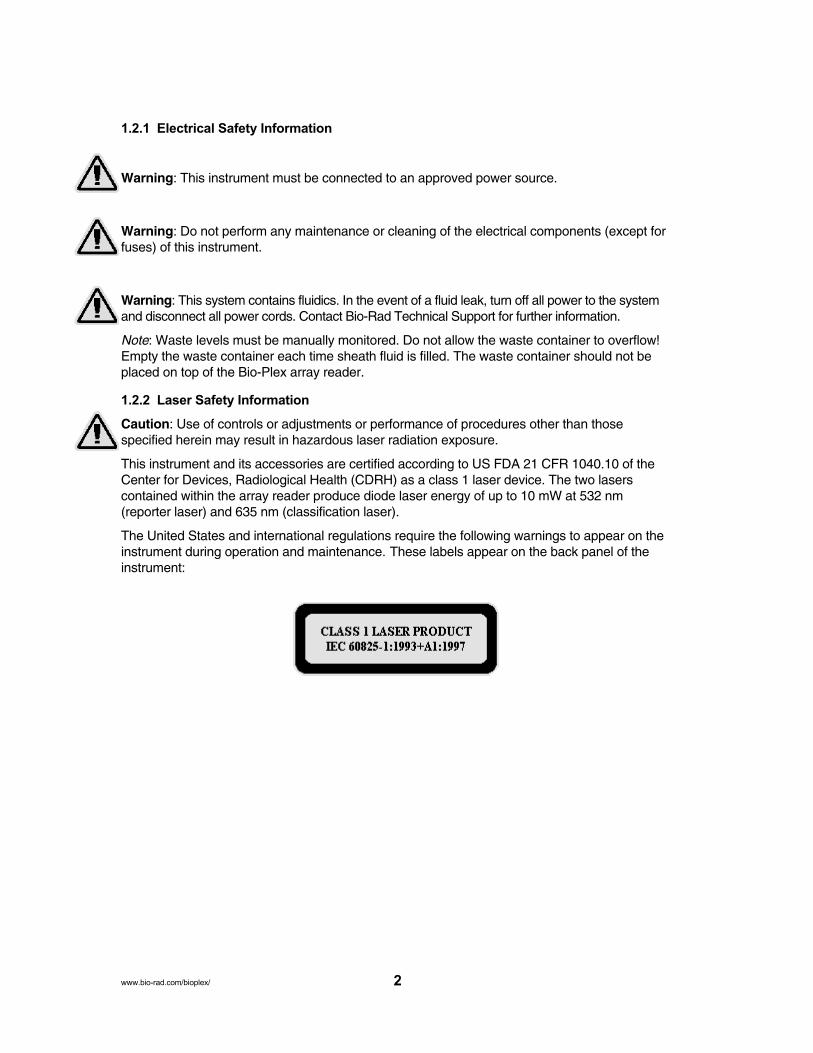
1.2.2 Laser Safety Information
Caution: Use of controls or adjustments or performance of procedures other than those specified herein may result in hazardous laser radiation exposure.
This instrument and its accessories are certified according to US FDA 21 CFR 1040.10 of theCenter for Devices, Radiological Health (CDRH) as a class 1 laser device. The two lasers contained within the array reader produce diode laser energy of up to 10 mW at 532 nm(reporter laser) and 635 nm (classification laser).
The United States and international regulations require the following warnings to appear on the instrument during operation and maintenance. These labels appear on the back panel of theinstrument:
www.bio-rad.com/bioplex/
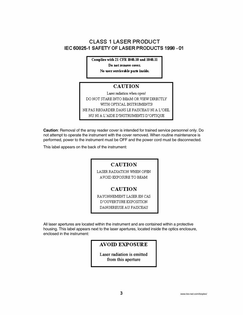
Caution: Removal of the array reader cover is intended for trained service personnel only. Donot attempt to operate the instrument with the cover removed. When routine maintenance isperformed, power to the instrument must be OFF and the power cord must be disconnected.
This label appears on the back of the instrument:
All laser apertures are located within the instrument and are contained within a protective housing. This label appears next to the laser apertures, located inside the optics enclosure,enclosed in the instrument:
3 www.bio-rad.com/bioplex/

1.2.3 Mechanical Safety Information
Caution: During operation, this system contains exposed, moving parts. Risk of personal injuryis present. Keep hands and fingers away from the sample probe and the syringe arm, as wellas the microplate platform during operation.
Note: Access doors must be closed while operating the Bio-Plex 200 system.
1.2.4 Biological Safety Information
Warning: All human and animal samples may contain hazardous infectious agents. Follow appropriate biosafety procedures when handling these products and any containers.
Observe all local, state, and federal biohazard handling regulations when disposing of biohazardous waste material.
1.2.5 Blue Indicator Light
Note: The blue lights above the sample arm, on the microplate platform, and on the high-throughput fluidics (HTF) system indicate the on/off status of the respective system components. The blue light emitting diode (LED) does not emit laser light or light in the UVspectrum.
Section 2Introduction
2.1 The Bio-Plex Suspension Array System and Multiplexing Technology
The Bio-Plex suspension array system is a unique and complete system comprising a 96-wellfluorescent microplate reader, Bio-Plex Manager™ software, validation and calibration kits, andassays. The system is designed, manufactured, and tested as a fully integrated system toensure accurate and reproducible assay results that are comparable across different laboratories.Centered around a flow-based dual laser detector with real-time digital signal processing, theBio-Plex 200 system is able to distinguish up to 100 different families of color-coded, monodispersepolystyrene beads, each bearing a different homogeneous capture assay (but all using the samesignal molecule) in a single 50 µl sample. This high degree of multiplexing dramatically increasesthe amount of useful information from rare or volume-limited samples, such as mouse and ratserum, and allows you to investigate analyte and biomarker interrelationships that would nothave been possible with traditional analysis systems. A microplate platform allows the automatedanalysis of 96-well plates. The throughput of samples using this system will allow analysis ofmore than 9,600 assay points in 30 min in a 96-well plate.
The Bio-Plex suspension array system uses up to 100 color-coded bead sets, each of whichmay be conjugated with a unique specific reactant. Each reactant is specific for a different targetanalyte. Reactants can include enzyme substrates, receptors, antigens, and antibodies, to create,for example, a capture sandwich immunoassay. To perform a multiplex assay, sample andreporter molecules are allowed to react with the conjugated bead mixture in microplate wells.The flow-based Bio-Plex 200 system identifies each specific reaction based on bead color, and quantitates it. The magnitude of the reaction is measured using fluorescently-labeled reportermolecules also specific for each target analyte. Bio-Plex Manager software automates data analysisand generation of detailed summary reports. With the Bio-Plex suspension array system you can:
• Simultaneously quantitate up to 100 analytes per sample from culture media and serum
• Automatically analyze up to 96 samples in 30 min
• Instantly customize your assay by mixing Bio-Plex assays, or create your own assays
• Dramatically increase the amount of useful data obtained from a single sample
For more specific or updated information, visit us at www.bio-rad.com/bio-plex/
4www.bio-rad.com/bioplex/
2.2 Description of System Components
The Bio-Plex 200 system is comprised of the following components:
• Array reader — combines 2 lasers, fluidics, and real-time digital signal processing to distinguishup to 100 different color-coded different color-coded bead sets, each representing a differentassay
• Microplate platform — automates the reading of 96-well plates, yielding up to 9,600 datapoints in ~ 35 min
• PC and monitor — controls the Bio-Plex suspension array system via Bio-Plex Managersoftware
• MCV (maintenance, calibration, and validation) plate III — automates the maintenance, calibration, and validation functions of the array reader
• Calibration kit — contains beads to standardize daily signal output and ensure unit-to-unitreproducibility of the reader
• Validation kit — contains beads to validate the operational specifications of the reader,including accuracy, linearity, dynamic range, slope, fluidics, and optical alignment
• Optional HTF system — delivers up to 20 L of sheath fluid without user intervention
• Sheath fluid cube — contains 20 L of sheath fluid (1x) for the array reader
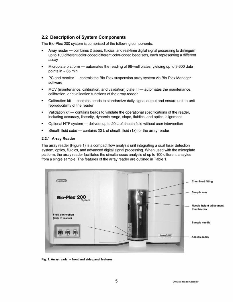
2.2.1 Array Reader
The array reader (Figure 1) is a compact flow analysis unit integrating a dual laser detection system, optics, fluidics, and advanced digital signal processing. When used with the microplateplatform, the array reader facilitates the simultaneous analysis of up to 100 different analytesfrom a single sample. The features of the array reader are outlined in Table 1.
Fig. 1. Array reader – front and side panel features.
5 www.bio-rad.com/bioplex/
Fluid connection
(side of reader)
Cheminert fitting
Sample arm
Sample needle
Needle height adjustment
thumbscrew
Access doors

Table 1. Array Reader Front and Side Panel Features.
Feature DescriptionSample arm The sample arm transports the sample from the 96-well
microtiter plate in the microplate platform to the cuvette.Upon operation, the carriage drops automatically to themicrotiter plate for sample retrieval.
Sample needle A stainless-steel sample needle acquires sample fromthe 96-well plate in the microplate platform.
Cheminert fitting Covered by the sample arm cover, this fitting may be disconnected to allow replacement of the sample needleif necessary.
Access doors There are two access doors on the face of the array reader. The centermost door allows access to thesyringe. The left door provides access to the sheath filter.
Air, waste fluid, Located on the side of the instrument, these connectors and sheath fluid couple directly to the sheath and waste fluid connectors.connectors The air connector is green, the sheath connector is blue,
and the waste fluid connector is orange.
The rear panel features of the array reader are shown in Figure 2 and described in Table 2.
Fig. 2. Array reader – rear panel features.
6www.bio-rad.com/bioplex/
Power connector
Communication
port P1
Communication
port P2
Air filter and
access door
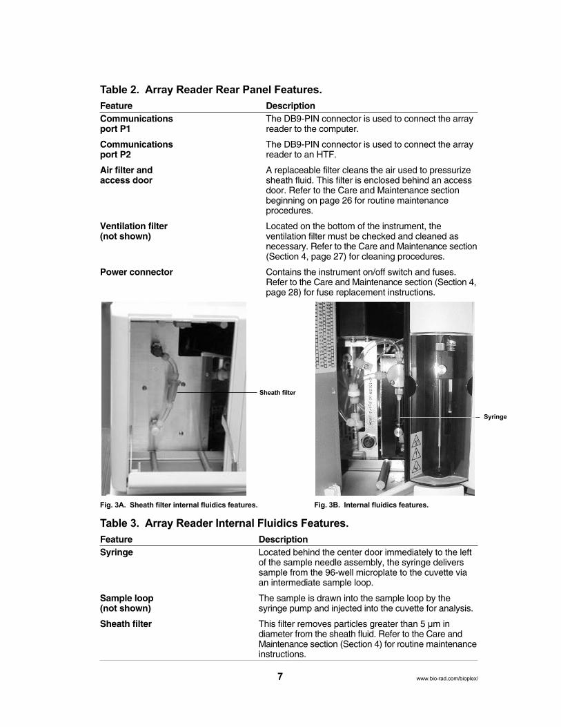
Table 2. Array Reader Rear Panel Features.
Feature DescriptionCommunications The DB9-PIN connector is used to connect the array port P1 reader to the computer.
Communications The DB9-PIN connector is used to connect the arrayport P2 reader to an HTF.
Air filter and A replaceable filter cleans the air used to pressurizeaccess door sheath fluid. This filter is enclosed behind an access
door. Refer to the Care and Maintenance sectionbeginning on page 26 for routine maintenance procedures.
Ventilation filter Located on the bottom of the instrument, the (not shown) ventilation filter must be checked and cleaned as
necessary. Refer to the Care and Maintenance section(Section 4, page 27) for cleaning procedures.
Power connector Contains the instrument on/off switch and fuses.Refer to the Care and Maintenance section (Section 4,page 28) for fuse replacement instructions.
Fig. 3A. Sheath filter internal fluidics features. Fig. 3B. Internal fluidics features.
Table 3. Array Reader Internal Fluidics Features.
Feature DescriptionSyringe Located behind the center door immediately to the left
of the sample needle assembly, the syringe deliverssample from the 96-well microplate to the cuvette viaan intermediate sample loop.
Sample loop The sample is drawn into the sample loop by the (not shown) syringe pump and injected into the cuvette for analysis.
Sheath filter This filter removes particles greater than 5 µm in diameter from the sheath fluid. Refer to the Care andMaintenance section (Section 4) for routine maintenanceinstructions.
7 www.bio-rad.com/bioplex/
Sheath filter
Syringe

2.2.2 Microplate Platform
The microplate platform (Figures 4 and 5) allows the automated processing of samples from a96-well microplate. The features of the microplate platform are outlined in Table 4.
Fig. 4. Microplate platform – front view.
Fig. 5. Microplate platform – back panel view.
Table 4. Microplate Platform Features.
Feature DescriptionAccess door This door provides access to the assay plate holder.
Operation of the access door is controlled throughthe system software.
Blue shipping pin A temporary fitting for shipping purposes.
Communications port A DB9-PIN connector used to connect the microplateplatform to the computer.
Power connector Contains the instrument on/off switch and fuses.Refer to the Care and Maintenance section (Section 4,page 28) for fuse replacement instructions.
8www.bio-rad.com/bioplexsystem/
Blue shipping pin
Access door
Power connector Communications port
2.2.3 HTF
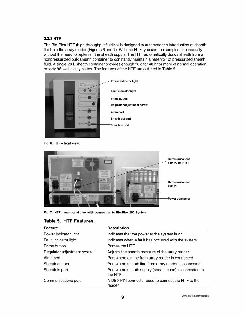
The Bio-Plex HTF (high-throughput fluidics) is designed to automate the introduction of sheathfluid into the array reader (Figures 6 and 7). With the HTF, you can run samples continuouslywithout the need to replenish the sheath supply. The HTF automatically draws sheath from anonpressurized bulk sheath container to constantly maintain a reservoir of pressurized sheathfluid. A single 20 L sheath container provides enough fluid for 48 hr or more of normal operation,or forty 96-well assay plates. The features of the HTF are outlined in Table 5.
Fig. 6. HTF – front view.
Fig. 7. HTF – rear panel view with connection to Bio-Plex 200 System.
Table 5. HTF Features.
Feature Description
Power indicator light Indicates that the power to the system is on
Fault indicator light Indicates when a fault has occurred with the system
Prime button Primes the HTF
Regulator adjustment screw Adjusts the sheath pressure of the array reader
Air in port Port where air line from array reader is connected
Sheath out port Port where sheath line from array reader is connected
Sheath in port Port where sheath supply (sheath cube) is connected tothe HTF
Communications port A DB9-PIN connector used to connect the HTF to thereader
9www.bio-rad.com/bioplex/
Power indicator light
Fault indicator light
Prime button
Regulator adjustment screw
Air in port
Sheath out port
Sheath in port
Power connector
Communications
port P1
Communications
port P2 (to HTF)

2.2.4 Computer and Monitor
The Bio-Plex 200 system may be supplied with a computer. If so, please transfer the computer’sregistration to your company’s name following unpacking.
2.2.5 Maintenance, Calibration, and Validation Plate
The Bio-Plex maintenance, calibration, and validation (MCV) plate III (Figure 8) is a specially designedaccessory to facilitate automated system startup, calibration and shut-down procedures, as well as validation routines used to qualify the performance of the array reader. It is designed for use with theBio-Plex validation kit to verify the performance of the instrument. Sized like a 96-well microplate, itcontains labeled wells for bead solutions as well as larger reservoirs for system wash and sterilizationsolutions.
Fig. 8. Maintenance, calibration, and validation (MCV) plate III.
2.3 Recommended Additional Equipment (not provided)
Surge protector
We recommend the use of a 6-outlet surge protector, with a minimum surge current of 12,000 A;power, 1,500 W; clamping voltage, 336 V; clamping response, <500 psec; maximum leakagecurrent, <50 µA. UL-listed (for USA user), CSA-certified, CE-marked (for use outside USA). Seewww.alliedelec.com and part number 575-9715.
Uninterruptible Power Supply (UPS)
We recommend the use of an uninterruptible power supply (UPS) to protect your system from apower outage. Choose a supply that can provide 1,050 W for at least 45 min. The UPS shouldbe UL-listed, CSA-certified, and CE-marked when used internationally.
2.4 Bio-Plex Assays
The Bio-Plex assays have been carefully integrated into the Bio-Plex 200 system to ensureseamless operation and accurate, reproducible results. For more specific information, consultBio-Plex assay manuals or visit our web site at www.bio-rad.com/bio-plex/
Bio-Rad offers a series of preformatted kits for your convenience. Other xMAP assays that utilizethe Luminex technology can be run on the system. Bio-Rad also offers mixed-to-order assaypanels of any combination of available analytes. Visit www.bio-rad.com/bio-plex/x-plex/ fordetails.
10www.bio-rad.com/bioplex/

Section 3InstallationAn authorized Bio-Rad service representative will set up the Bio-Plex 200 system in your laboratory. The following general setup procedure is provided here for reference.
3.1 Unpacking
An authorized Bio-Rad service representative will install your Bio-Plex 200 system in your laboratory. If, upon inspection of the shipping containers, you suspect that damage to the contentsmay have occurred, contact Bio-Rad Technical Support.
Warning: Due to the weight of the array reader, it is recommended that two people, one oneach side of the instrument, lift the system from the bottom.
Warning: The array reader contains sensitive optics. Do not jar the instrument when unpacking.
3.2 System Location
Selection of an appropriate location for your Bio-Plex 200 system is critical for optimal performance.Following is a list of recommended placement conditions.
1. Place on a clean, flat, and stable surface free of excessive dust or moisture. This surfacemust be free of other instrumentation that may cause vibration.
2. Do not obstruct the area below the array reader, and allow at least 2" of clearance aroundthe machine.
3. The ambient temperature should be stable and within the range of 15–30°C (21°C is optimal),and the relative humidity should not exceed 80%, noncondensing. It is preferable to placethe instrument in a location where the temperature does not deviate by more than ± 2°C.Avoid drafty locations as this may contribute to excessive temperature fluctuation.
4. The maximum distance between the computer and the microplate platform and array readershould be 1.5 m (5 ft), the length of the communications cable supplied with the instruments.
5. Do not place any items on top of the array reader. The cover is not designed to supportobjects and thus the optics could be damaged.
6. If installing the HTF, allow an area ~3 ft below the array reader for the 20 L sheath fluidcube.
Note: The array reader contains sensitive optics that can be forced out of alignment through improperhandling and unnecessary moving. It is recommended that an authorized service representativemove your system. Following any system moves, it is necessary to validate the optical alignmentand report any changes. Refer to the Bio-Plex validation kit manual for validation of the opticalalignment.
11 www.bio-rad.com/bioplex/
3.3 Microplate Platform Setup
The microplate platform should be shipped with the following items:
• Microplate platform• Power cord• Communication cable• Needle guide• 2 sample needles (11.7 cm/4.6 in)• Shield
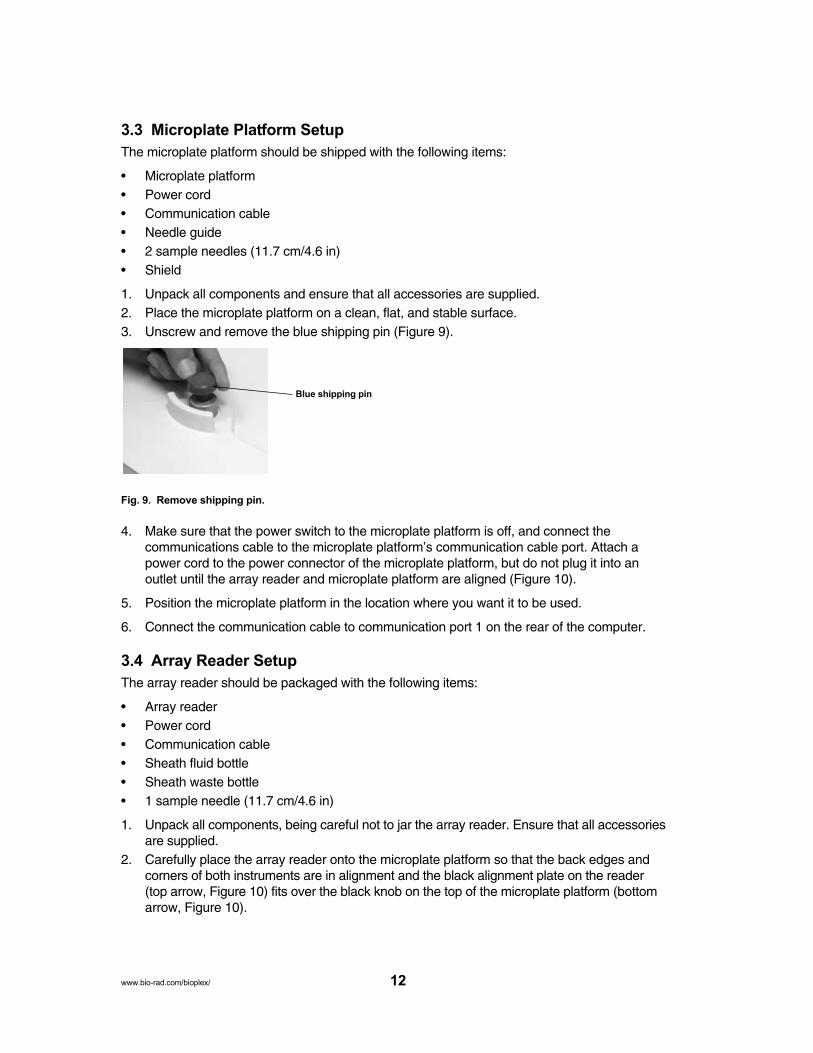
1. Unpack all components and ensure that all accessories are supplied.2. Place the microplate platform on a clean, flat, and stable surface.3. Unscrew and remove the blue shipping pin (Figure 9).
Fig. 9. Remove shipping pin.
4. Make sure that the power switch to the microplate platform is off, and connect the communications cable to the microplate platform’s communication cable port. Attach apower cord to the power connector of the microplate platform, but do not plug it into an outlet until the array reader and microplate platform are aligned (Figure 10).
5. Position the microplate platform in the location where you want it to be used.
6. Connect the communication cable to communication port 1 on the rear of the computer.
3.4 Array Reader Setup
The array reader should be packaged with the following items:
• Array reader• Power cord• Communication cable• Sheath fluid bottle• Sheath waste bottle• 1 sample needle (11.7 cm/4.6 in)
1. Unpack all components, being careful not to jar the array reader. Ensure that all accessoriesare supplied.
2. Carefully place the array reader onto the microplate platform so that the back edges andcorners of both instruments are in alignment and the black alignment plate on the reader(top arrow, Figure 10) fits over the black knob on the top of the microplate platform (bottomarrow, Figure 10).
12www.bio-rad.com/bioplex/
Blue shipping pin

Warning: Get a helper. One person should not attempt to lift the array reader. To avoidback injury, always bend your knees and keep a straight back when lifting heavy objects.
Fig. 10. Reader aligned on top of microplate platform.
3. Plug the microplate platform power cord into an approved outlet. A surge protector is recommended to protect the microplate platform from power fluctuations. SeeRecommended Additional Equipment Not Provided on page 10.
4. A communication cable is supplied to connect into communication port 1 (P1) at the rear ofthe array reader and to a USB port at the back of the computer. However, do not make thisconnection until after the software is installed. Connect a power cord to the array reader’spower connector.
5. Connect the communication cable in the microplate platform communication port to communication port 1 (COM1) of the computer (Figure 11).
6. Plug the array reader and microplate platform power cords into a properly grounded electrical outlet.
13 www.bio-rad.com/bioplex/

Fig. 11. Completed connections of computer and monitor to the Bio-Plex suspension array system.
3.5 Connecting the Sheath Fluid and Waste Containers
1. Attach the 1.5 L waste bottle (orange-ringed cap) to the orange Waste connector on the leftside of the array reader. An audible click indicates proper connection. Lubricating the rubber O-rings with water can facilitate attaching these connectors. The waste bottle shouldnot be placed on top of the instrument.
Warning: Waste levels must be monitored. Do not allow the waste bottle to overflow!Empty the waste bottle each time the sheath fluid container is filled.
2. Attach the 1.0 L sheath bottle (blue-ringed cap) to the array reader as follows:
a) Connect the air line (uppermost tube) to the green connector on the array reader.
b) Connect the sheath fluid line to the blue connector.
An audible click will be heard when the hoses are properly connected. For proper operation, the sheath bottle must be placed at the same level as the Bio-Plex suspensionarray system, and the cap tightened.
Warning: Do not switch the caps on the waste and sheath bottles. The orange-ringed capmust go on the waste bottle and the blue-ringed cap must go on the sheath bottle for thereader to function properly.
Fig. 12. Waste and sheath fluid bottle connections.
14www.bio-rad.com/bioplex/
Empty when waste
fluid reaches this level
Fill when sheath fluid
reaches this level
Reader
communication
USB port
Reader communication
port P1 (upper port)
HTF communication
port P2 (lower port)
Microplate platform
serial port
Microplate platform
port
3. Fill the sheath fluid bottle with sheath fluid supplied in the 20 L cube container (catalog #171-000055) to just below the air intake. Tighten cap (Figure 12).
Warning: In order to maintain system pressure, the sheath fluid bottle cap must be tight.Do not overtighten or seal will be lost.
Note: To set up the 20 L sheath fluid cube container for use, remove tape from box and lift offthe round white cover. Pull spout out of the box. Unscrew cap and replace it with the spigot capincluded in the box.
Note: The waste bottle must be emptied and the sheath bottle must be refilled after reading twoassay plates.
Note: If you have a HTF it should be set up after the initial reader setup is complete.
3.6 Computer and Monitor Connections
When you receive the Bio-Plex 200 system, please transfer the computer’s registration to yourcompany’s name.
1. Unpack the computer and place it on a bench adjacent to the array reader. Typical computerplacement is to the right of the array reader since sheath and waste fluid bottles are locatedon the instrument’s left side. DO NOT place the computer on top of the array reader.
2. Unpack the monitor and place it on top of the computer, or in another suitable place.DO NOT place the monitor on top of the array reader.
3. Connect the monitor to the computer, install the power cords into the respective power connectors, and plug into an approved outlet.
4. Connect the keyboard and mouse.
5. Your computer will be loaded with Bio-Plex Manager software during installation. SeeSection 3.7 for software loading requirements.
3.7 Software Installation
3.7.1 System Software Loading
Your computer will be loaded with Bio-Plex Manager software during installation. However, inthe event that it is necessary to reload the software, proceed as follows:
1. Disconnect the communication cable that connects the computer to the array reader at thecomputer (USB port) if not already done.
2. Insure that the array reader, microplate platform, and HTF unit are turned off.
3. Insert the Bio-Plex Manager CD-ROM into the CD drive of the computer.
4. Select Install Bio-Plex Manager.
5. After installation, remove the installation disk.
6. Attach the HASP key.
7. Reconnect the USB communication cable and turn on the array reader, microplate platform,and HTF unit.
Note: Please refer to the Bio-Plex Manager software manual for detailed installation instructions.
15 www.bio-rad.com/bioplex/
3.7.2 Communication Ports
Bio-Plex Manager will automatically detect the port configuration.
3.8 Installing or Changing the Sample Needle
3.8.1 Installing/Changing the Long Sample Needle
Warning: Turn the power to the array reader off before installing or changing the sample needle.
For use with the microplate platform, a long sample needle (11.7 cm/4.6 in) must be installed. Aspare long needle is shipped with the microplate platform.
1. Make sure that the power to the array reader is switched off. Make sure the power cord isunplugged from the outlet.
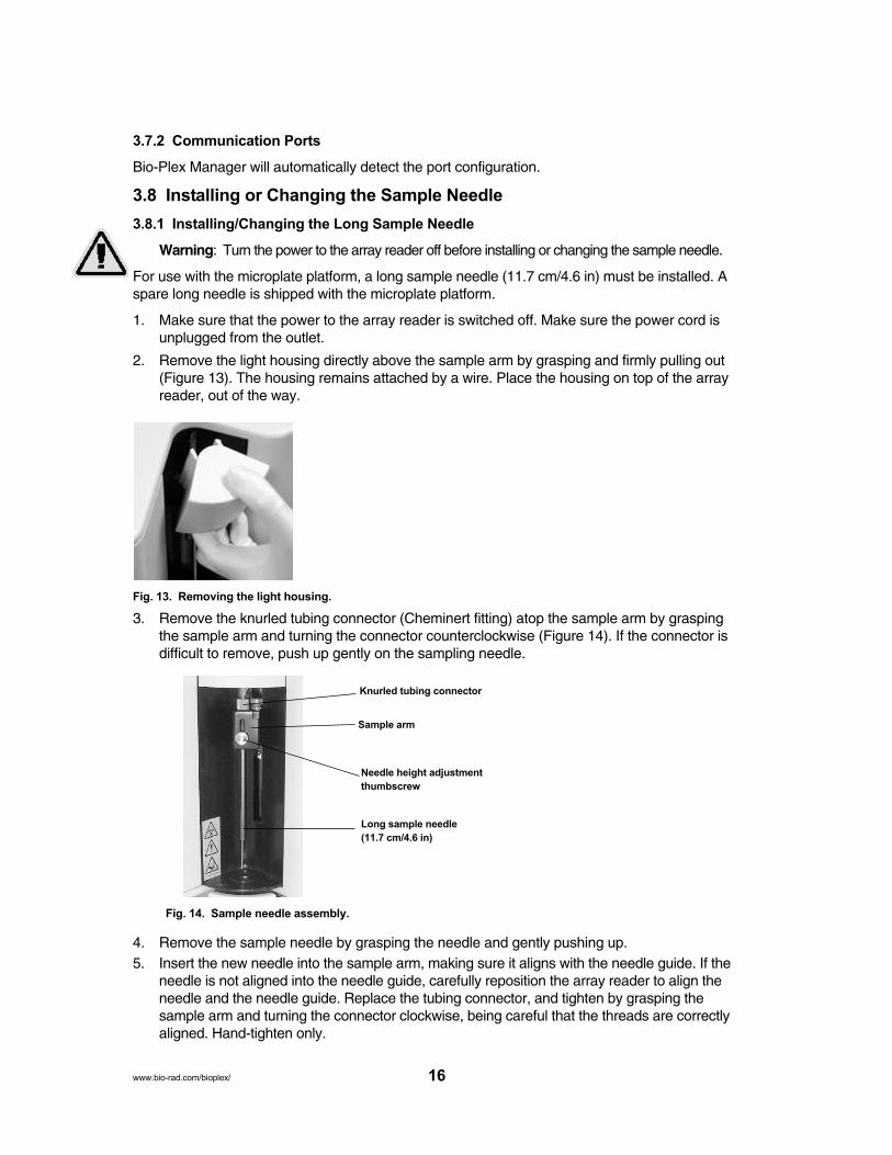
2. Remove the light housing directly above the sample arm by grasping and firmly pulling out(Figure 13). The housing remains attached by a wire. Place the housing on top of the arrayreader, out of the way.
Fig. 13. Removing the light housing.
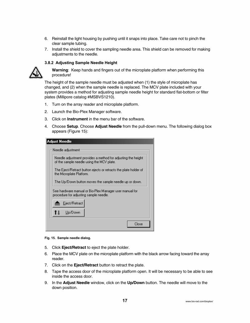
3. Remove the knurled tubing connector (Cheminert fitting) atop the sample arm by graspingthe sample arm and turning the connector counterclockwise (Figure 14). If the connector isdifficult to remove, push up gently on the sampling needle.
Fig. 14. Sample needle assembly.
4. Remove the sample needle by grasping the needle and gently pushing up.5. Insert the new needle into the sample arm, making sure it aligns with the needle guide. If the
needle is not aligned into the needle guide, carefully reposition the array reader to align theneedle and the needle guide. Replace the tubing connector, and tighten by grasping thesample arm and turning the connector clockwise, being careful that the threads are correctlyaligned. Hand-tighten only.
16www.bio-rad.com/bioplex/
Knurled tubing connector
Sample arm
Long sample needle
(11.7 cm/4.6 in)
Needle height adjustment
thumbscrew
6. Reinstall the light housing by pushing until it snaps into place. Take care not to pinch theclear sample tubing.
7. Install the shield to cover the sampling needle area. This shield can be removed for makingadjustments to the needle.
3.8.2 Adjusting Sample Needle Height
Warning: Keep hands and fingers out of the microplate platform when performing this procedure!
The height of the sample needle must be adjusted when (1) the style of microplate haschanged, and (2) when the sample needle is replaced. The MCV plate included with your system provides a method for adjusting sample needle height for standard flat-bottom or filterplates (Millipore catalog #MSBVS1210).
1. Turn on the array reader and microplate platform.
2. Launch the Bio-Plex Manager software.
3. Click on Instrument in the menu bar of the software.
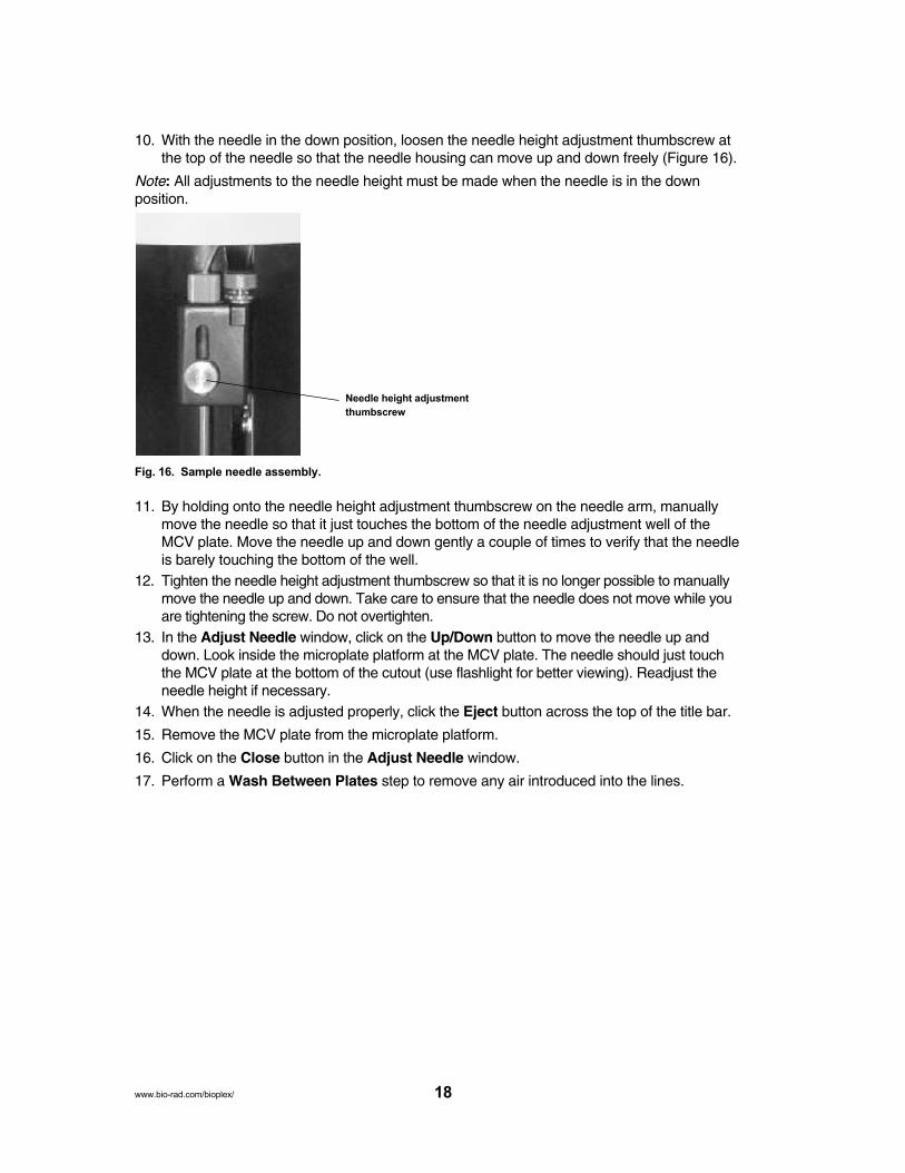
4. Choose Setup. Choose Adjust Needle from the pull-down menu. The following dialog boxappears (Figure 15):
Fig. 15. Sample needle dialog.
5. Click Eject/Retract to eject the plate holder.
6. Place the MCV plate on the microplate platform with the black arrow facing toward the arrayreader.
7. Click on the Eject/Retract button to retract the plate.
8. Tape the access door of the microplate platform open. It will be necessary to be able to seeinside the access door.
9. In the Adjust Needle window, click on the Up/Down button. The needle will move to thedown position.
17 www.bio-rad.com/bioplex/
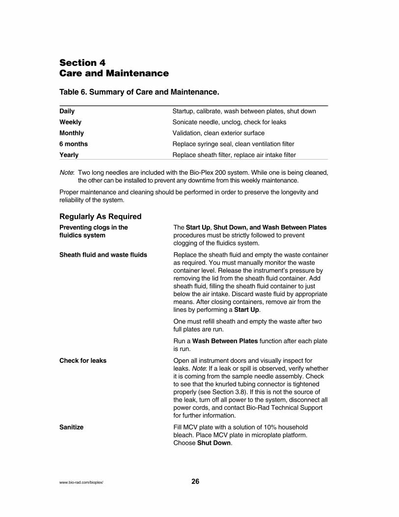
10. With the needle in the down position, loosen the needle height adjustment thumbscrew atthe top of the needle so that the needle housing can move up and down freely (Figure 16).
Note: All adjustments to the needle height must be made when the needle is in the down position.
Fig. 16. Sample needle assembly.
11. By holding onto the needle height adjustment thumbscrew on the needle arm, manuallymove the needle so that it just touches the bottom of the needle adjustment well of theMCV plate. Move the needle up and down gently a couple of times to verify that the needleis barely touching the bottom of the well.
12. Tighten the needle height adjustment thumbscrew so that it is no longer possible to manuallymove the needle up and down. Take care to ensure that the needle does not move while youare tightening the screw. Do not overtighten.
13. In the Adjust Needle window, click on the Up/Down button to move the needle up anddown. Look inside the microplate platform at the MCV plate. The needle should just touchthe MCV plate at the bottom of the cutout (use flashlight for better viewing). Readjust theneedle height if necessary.
14. When the needle is adjusted properly, click the Eject button across the top of the title bar.
15. Remove the MCV plate from the microplate platform.
16. Click on the Close button in the Adjust Needle window.
17. Perform a Wash Between Plates step to remove any air introduced into the lines.
18www.bio-rad.com/bioplex/
Needle height adjustment
thumbscrew

3.9 Initial System Priming
This procedure is to be performed only during the initial installation of the array reader.
1. Fill the maintenance, calibration, and validation (MCV) plate (Figure 17) with deionizedwater and 70% isopropyl alcohol in the appropriate wells.
Fig. 17. MCV plate III.
2. Click the Eject icon. Insert the MCV plate into the microplate platform. Click Retract.
3. Choose Instrument from the main menu bar. Choose Additional Functions, followed byPrime.
4. Inspect the waste line outside the instrument for air pockets. Repeat the priming procedureuntil no air pockets are observed in the waste line outside of the array reader. This mayrequire a few priming cycles.
5. Choose Instrument from the main menu bar. Choose Additional Functions. ChooseAlcohol Flush. Wait for function to complete.
6. Choose Instrument from the main menu bar. Choose Additional Functions. ClickWash. Wait for function to complete.
7. Repeat Wash two more times.
3.10 Resetting Instrument Pressure Settings
1. After the system has been primed it is necessary to run the Reset Instrument PressureSettings utility for optimal instrument performance. The utility initially sets the CalibrationPressure and the Manufacturing Pressure to the same value. Subsequently, whenever acalibration is performed the Calibration Pressure will be updated, but it should not divergevery far from the original Manufacturing Pressure setting unless there is a system problem.The settings are displayed in the Instrument Info window under the Device Status tab.
2. The Reset Instrument Pressure Settings utility should be performed first using thesheath fluid bottle attached to the system. If a HTF is included with the system, this utilitywill be rerun in the HTF Setup section which follows.
3. With the array reader off and Bio-Plex Manager software closed, go the the Utilities folderin Bio-Plex Manager 4.1 (go to Start > Programs > Bio-Plex Manager 4.1 > Utilities). Clickon Reset Instrument Pressure Settings. This will set up the system to set the instrument pressures the next time Bio-Plex Manager is launched.
19 www.bio-rad.com/bioplex/

4. Power on the array reader and start Bio-Plex Manager software. As the program opens,you will see a message that the system is Updating system settings. A message notingthat the settings were successfully updated will be displayed when the process is complete.
5. Restart the array reader and Bio-Plex Manager software.
3.11 HTF Setup
1. Unpack all components. Ensure that all accessories are supplied.
2. Start with the original sheath fluid and waste containers connected to the array reader. Checkthat the sheath fluid container is filled just below the air intake valve.
3. Make sure the array reader is turned on, and start the Bio-Plex Manager software.
4. From the Instrument menu, select Additional Functions, then select Prime.
5. Open the Instrument Information window and select the Device Status tab.
Fig. 18. Device status window.
6. After the pressure has stabilized, record the air and sheath pressure.
Air pressure: ________ psi
Sheath pressure________ psi
Save this information. You will need it later in the installation procedure, and you will alsoneed to refer to it if you use the array reader with the original sheath fluid container again.
7. At the end of the prime cycle, disconnect the sheath fluid container. Store it in a safe place.If you plan to use the HTF waste line, disconnect the waste container as well.
Note: It is important to document your instrument’s original sheath pressure in case bottlesare used.
8. Place the HTF next to the sheath fluid connection on the array reader. Do not place theHTF on top of the array reader. Place the sheath cube 3–4 ft below the level of the arrayreader and HTF. Figure 19 shows a typical setup.
Warning: Placing the sheath container on the same level or higher than the Bio-Plex readercan draw sheath fluid into the array reader and damage the system.
20www.bio-rad.com/bioplex/

Fig. 19. HTF setup.
9. Make the following connections to connect the HTF to the array reader:• Connect the sheath fluid line (blue fitting) to the Sheath Out connector on the front of the
HTF. Lubricating the rubber O-rings with water facilitates attaching these connectors• Connect the air line (green fitting) to the Air In connector on the front of the HTF• Connect the sheath fluid line to the sheath fluid connector on the side of the array reader
(blue fitting)• Connect the air line to the air connector on the side of the array reader (green fitting)• If you are using the HTF waste line, connect the waste line tubing to the waste
connector on the side of the reader, and run the other end of the waste line into anappropriate biohazard receptacle. Cut off excess tubing, and make sure the wastereceptacle is level with the array reader or no more than 3 ft below it. Note: the wastecontainer must be vented
• Connect the sheath fluid intake line (white fitting) to the Sheath In connector in thefront of the HTF
• Connect the communication cable to the DB9-PIN connector on the back of the HTFsystem. Connect the other end to communication port 2 (P2) on the back of the Bio-Plex array reader
• Connect the power cord to the back of the HTF and plug the other end into anapproved outlet
Note: If you are using the 1.5 L waste bottle included with the Bio-Plex system, be sure toempty it after every two plates are read.
21 www.bio-rad.com/bioplex/

Note: You may use the additional waste line provided with the system to drain to a largerwaste container. The large waste container waste must be positioned so that it is nomore than 3 or 4 ft below the array reader. Please note that the instrument flow rate isinfluenced by waste container placement, which may affect performance.
10. Lower the stainless-steel filter end of the sheath fluid line to the bottom of a full box ofsheath fluid. Secure the cap on the sheath fluid box. Position the sheath fluid container onthe floor so that the cap is on the top.
11. Turn on the power to the HTF; the HTF should automatically prime itself. You will hear theHTF pump turn on. When the HTF reservoir is about 2/3 full, it will stop priming automatically.
12. Open the center access door on the array reader. Use a screwdriver to turn the regulatorscrew fully clockwise, then one half-turn back (Figure 20). This may require several fullturns of the regulator screw.
Fig. 20. Regulator screw adjustment.
13. From the Instrument menu select Additional Functions, and then Prime. During thisprime cycle use a screwdriver to adjust the regulator on the front of the HTF system (notshown). Adjust it until the sheath pressure displayed in the Information Box reads thesame as the sheath pressure you recorded in step 6. This may take many turns. The system should stabilize at this sheath pressure. The air pressure should be the same asyou recorded in step 6, within 0.1 psi.
If the Prime cycle ends before you have completed the adjustment, select Prime again andcontinue to adjust the regulator.
14. When the pressure has been set it is critical that the flow rate be verified. Collect theflowthrough to waste for 2 min in a graduated container capable of estimating volume to 0.5 ml. The volume collected should be 10.5 to 11.5 ml. Use universal precautions to avoidcontamination if the system has been used with human blood, body fluids or tissues. Tominimize the biological hazard, use the flow rate test kit available from Bio-Rad (catalog #800-0502). If the flow rate is too low increase the pressure by turning the regulator screwon the HTF unit clockwise. If the rate is too high, decrease the pressure by turning the regulator screw counterclockwise. Start by turning the regulator screw a quarter-turn in theappropriate direction then retesting the flow rate. Continue until the flow rate is within thespecification.
22www.bio-rad.com/bioplex/
Regulator

15. Because the flow rate in step 14 is adjusted by altering the system pressure, it is necessaryto repeat steps 3 to 5 of Section 3.10 (Resetting Instrument Pressure Settings).
Note: It is necessary to run the Reset Instrument Pressure Settings utility whenever the flowrate (or system pressure) is changed. This is a rare occurrence in normal operation.
3.12 Vacuum Manifold Setup
Bio-Rad recommends the use of the Millipore multiscreen separations system (catalog #MAVM0960R) for preparing Bio-Plex assays. A setup and validation procedure for this apparatus is included here. More specific instructions for the setup of the apparatus as well asspecific product information may be found in the Millipore multiscreen separations system userguide. Note that depending on the type of samples used in Bio-Plex assays, the pressure necessary to achieve optimal results may be different. If you choose to use your laboratory(house) vacuum system, be aware that fluctuations in vacuum pressure may be extremeenough so that you may need to purchase and integrate a pressure regulator. Alternatively, youmay also purchase a vacuum pump to ensure optimal steady-state vacuum pressure. Finally,once you have calibrated your manifold, it is important to validate that this pressure is optimalfor performing Bio-Plex assays. Follow the verification procedure in this section closely for optimal results using Bio-Plex assays.
Equipment: Required
• Vacuum source — laboratory vacuum or vacuum pump• Pressure regulator (if extreme fluctuations in house vacuum are a problem)• Millipore multiscreen separations system (catalog # MAVM0960R)• Flat-bottom microplate (not a filter plate)• Millipore 96-well filtration plate (catalog # MSBVS1210)• Phosphate buffered saline• 8-channel pipet
3.12.1 System Setup
Setup of the Multiscreen Vacuum Manifold
Figure 21 illustrates the vacuum manifold setup and its attachment to a laboratory vacuumsource. For more specific details regarding the setup of the manifold, refer to the Millipore multiscreen separations system user guide.
Fig. 21. Vacuum manifold and vacuum source setup.
23 www.bio-rad.com/bioplex/

1 Make sure that the system has been set up according to the directions in the Millipore userguide.
Hint: Make sure that the connector leading to the vacuum control knob is perpendicular tothe manifold. This will ensure that no buffer travels to the vacuum control knob.
2 Place a 96-well flat-bottom microplate (not a filter plate) on the vacuum apparatus.
3. Make sure the gold vacuum control valve (Figure 22) is completely open (all colors showing).
4. Make sure the gray ON/OFF valve (Figure 23) is completely off (the knob should be perpendicular to the direction of the tubing attached to it).
Fig. 22. Gold vacuum control valve. Fig. 23. Gray ON/OFF valve.
5. Turn on the lab vacuum to maximum level and note this setting for performance of assays.In common lab vacuum systems, the lever should be turned so that it is parallel to the vacuum port. Alternatively, turn on the vacuum pump.
6. Slowly open the ON/OFF valve on the manifold to the ON position (parallel to the tubing).
7. Slowly turn the vacuum control valve clockwise until a slight vacuum sound is heard.
8. Press firmly on the 96-well plate (all four corners) until it is sealed securely by the vacuumon the apparatus.
9. Observe the pressure reading on the attached gauge (see below).
10. Adjust the ON/OFF valve and turn the calibration knob so that the gauge reads approximately1–2.5" Hg.
11. Close the lab vacuum until the 96-well plate is released from the apparatus.
12. Turn on the lab vacuum again, press on the 96-well plate, and look at the indicated pressureon the gauge again.
13. If the pressure is still approximately 1–2.5" Hg, the vacuum apparatus has been correctlycalibrated. If not, repeat the steps of the calibration procedure until the desired result isachieved.
14. Turn off the vacuum apparatus and proceed to Section 3.12.2, Validation of VacuumPressure.
Note: Do not make any further adjustments to the vacuum control valve.
3.12.2 Validation of Vacuum Pressure
Validating the Vacuum Manifold Pressure for a Bio-Plex Assay
1. Prewet all of the wells of a Millipore 96-well filter plate with 100 µl PBS.
2. Place the prewetted filter plate on the calibrated vacuum apparatus.
24www.bio-rad.com/bioplex/

3. Turn on the laboratory vacuum to maximum level (the same level that was used in the preceeding calibration procedure).
4. Press on the filter plate and note the time required to evacuate the solution from the wells.The time required should be 2–5 sec.
Note: It is important to perform this step exactly as you would perform a wash step in a Bio-Plex assay.
5. If the time required to evacuate the solution from the wells was less than 2 sec, the calibratedpressure is too high. If the time required is greater than 5 sec, the vacuum pressure is toolow.
6. If the pressure is too high (evacuation occurs too quickly), open the vacuum control valveslightly (so that fewer colors are showing) and repeat steps 1 through 5 until the evacuationtime is 2–5 sec.
7. If the pressure is too low, (evacuation occurs too slowly), close the vacuum control valveslightly (so that fewer colors are showing) and repeat steps 1 through 5 until the evacuationtime is 2–5 sec.
Note: It is a good practice to validate the vacuum pressure each day during the prewetting stepof the Bio-Plex assays. When you have added the assay buffer to the appropriate wells andevacuate the plate on the manifold, ensure that the time required to evacuate the plate is 2–5sec. This will verify that the manifold is calibrated correctly.
Tips
Listed below are a few key hints and recommendations for using the vacuum manifold. For amore complete listing of potential problems and solutions, consult the troubleshooting guide atthe end of this manual.
1. If you notice a large amount of fluctuation in your pressure using laboratory vacuum, youmay need to purchase and attach a pressure regulator to the vacuum line. Alternatively,you may purchase a vacuum pump to ensure optimal steady-state pressure. In either case,it is critical to correctly calibrate and validate the vacuum pressure before performing Bio-Plex assays.
2. If you notice that the plates are taking an extended amount of time to evacuate, you mayneed to replace the gaskets. See the Millipore multiscreen separations system user guidefor instructions on replacing the gaskets.
3. Do not allow the laboratory vacuum to continue aspirating the filter plate for more than 10 sec after the solutions are completely gone from the wells. This will result in a significant loss of beads.
4. It is recommended that you clean the manifold regularly. The frequency depends on thereagents you use and how often you use the manifold. Use mild soap or standard laboratorydetergent, bleach, or alcohol to clean all surfaces.
3.13 Performing System Validation
Prior to performing analyses with the Bio-Plex 200 system the instrument must be calibrated.Calibration should be done each day after startup is complete and the system is warmed up.You should also recalibrate if the instrument temperature changes by more than 2°C.
The user should verify that the system is performing according to specifications using the Bio-Plex validation kit. Validation should be performed monthly. Additionally, the user shouldrevalidate each time the array reader is moved or if there are problems with the array readerthat can’t be solved by other procedures. See the validation kit manual for complete system validation instructions.
25 www.bio-rad.com/bioplexsystem/
Section 4Care and Maintenance
Table 6. Summary of Care and Maintenance.
Daily Startup, calibrate, wash between plates, shut down
Weekly Sonicate needle, unclog, check for leaks
Monthly Validation, clean exterior surface
6 months Replace syringe seal, clean ventilation filter
Yearly Replace sheath filter, replace air intake filter
Note: Two long needles are included with the Bio-Plex 200 system. While one is being cleaned,the other can be installed to prevent any downtime from this weekly maintenance.
Proper maintenance and cleaning should be performed in order to preserve the longevity andreliability of the system.
Regularly As Required
Preventing clogs in the The Start Up, Shut Down, and Wash Between Platesfluidics system procedures must be strictly followed to prevent
clogging of the fluidics system.
Sheath fluid and waste fluids Replace the sheath fluid and empty the waste containeras required. You must manually monitor the wastecontainer level. Release the instrument’s pressure byremoving the lid from the sheath fluid container. Add sheath fluid, filling the sheath fluid container to just below the air intake. Discard waste fluid by appropriatemeans. After closing containers, remove air from thelines by performing a Start Up.
One must refill sheath and empty the waste after twofull plates are run.
Run a Wash Between Plates function after each plateis run.
Check for leaks Open all instrument doors and visually inspect forleaks. Note: If a leak or spill is observed, verify whetherit is coming from the sample needle assembly. Checkto see that the knurled tubing connector is tightenedproperly (see Section 3.8). If this is not the source ofthe leak, turn off all power to the system, disconnect allpower cords, and contact Bio-Rad Technical Supportfor further information.
Sanitize Fill MCV plate with a solution of 10% householdbleach. Place MCV plate in microplate platform.Choose Shut Down.
26www.bio-rad.com/bioplex/

Every Month
Clean exterior surfaces Disconnect the instrument from AC power by turningoff the power switch on the rear of the array readerand microplate platforms. Unplug both instrumentpower cords from the wall source. Wipe all exteriorsurfaces with mild germicidal detergent, followed by a10% bleach solution. Open both front doors of thearray reader and clean all accessible surfaces withdetergent followed by a 10% bleach solution. Dry thesheet metal surfaces to prevent corrosion.
Every 6 Months
Syringe seal Replace the syringe plunger’s seal every 6 months. Open the centermost door on the front of the array reader. Locate the syringe (a glass cylinder with a
Warning! metal rod). Unscrew the knob on the syringe arm (at Turn the unit OFF and the bottom of the syringe), and forcefully push the unplug the power cord syringe arm down. Unscrew the syringe from the top before replacing the syringe of its housing and pull the plunger out of the syringe. plunger! The syringe Remove and replace the plunger seal, and return the arm does not deactivate plunger to the syringe. Screw the syringe back into the when changing the plunger; top of its housing, return the syringe arm to its original injury could result if the position, and hand-tighten the screw on the syringe system is not unplugged. arm. Plug in the power cord and turn the array reader
on. Prime the instrument until any bubbles in thesyringe seal are eliminated, watching for any leaks inthe syringe area. When finished, close the center door.See Table 2 and Figure 3B (page 7).
Instrument ventilation filter Check the instrument ventilation filter every 6 months.Clean the filter only when soiled. Disconnect the arrayreader from AC power by turning off the power switch.Unplug the power cord from the wall source. On thebottom-left side of the array reader, push the clip inand gently slide the filter out. Clean the filter with avacuum or by placing it under running distilled water.Stand it upright to air-dry. Reinstall it with the arrowsfacing up.
Every Year
Sheath filter Change the sheath filter once a year. Disconnect thesheath fluid bottle before changing the filter. Separatethe filter and tubing from the retaining clips. Cut thetubing close to the filter on both sides of the filter.Connect the tubing to the new filter and return the filterand tubing to the retaining clips. Reconnect the sheathfluid bottle.
27 www.bio-rad.com/bioplex/

Air intake filter Replace the air intake filter every year. Disconnect the instrument from AC power by turning off the powerswitch on the rear of the array reader. Unplug both
Note: instrument power cords from the wall source. Looking Hold onto the tubing! Do at the back of the array reader, locate the panel at the not allow the tubing to fall top left. Remove the screw at the top of the panel and inside the instrument. open the panel door. Pull the filter 3–4 in from the unit.
Grasp the tubing. Remove the filter with one hand, andhold the tubing with the other hand. Connect a new filter to the tubing, position the filter inside the panel,and reattach the panel door to the unit.
As Required
Fuse replacement To replace the fuses, disconnect the array reader fromAC power by turning off the power switch on the rearof the instrument. Unplug the instrument power cordfrom the wall source. With a small, flathead screwdriver,open the module door and remove the red cartridge.Check both fuses for damage. Replace damagedfuses with the type specified on the sticker to the rightof the power connector.
Sample arm vertical height The vertical height determines how far into the samplewell or tube the sample needle goes when aspirating asample. It was set during installation of your system.To adjust sample needle height, see Section 3.8.2,Adjusting Sample Needle Height.
Shutting Down the Bio-Plex 200 System for Extended Periods of NonuseThoroughly flush with DI H2O Place the MCV plate in the instrument with DI H2O in
the reservoir labeled “DI H2O”. Replace the sheathfluid in the bottle or HTF with DI H2O. Perform 4 washcycles (for each cycle go to Instrument > AdditionalFunctions > Wash, then click OK). Next, perform 10prime cycles (for each cycle go to Instrument >Additional Functions > Prime, then click OK). Beforeusing the Bio-Plex again you must flush out the DI H2Oby reintroducing sheath fluid into the sheath bottle orHTF unit and performing 10 prime cycles.
28www.bio-rad.com/bioplex/

Section 5Troubleshooting
5.1 Troubleshooting Guide for Bio-Plex 200 System
Problem Possible Cause Solution
Message: Bio-Plex Manager Most Likely:has detected a problem with low bead number. Too few beads in the assay Check bead number calculations.
Plate not shaken Remove plate from array reader 10 min before analysis and shake for 10 sec.
Buffer volume in wells is too Resuspend in 125 µl. low (must be at least 125 µl) Perform Remove Bubbles.
Microbubble in cuvette Perform Remove Bubbles.Perform Unclog to verify fluidicsintegrity.
Low/no sheath fluid Refill sheath fluid, check sheath connections. Perform Start Up.
Possible clog Perform Unclog and rerun. If unsuccessful, repeat. Remove needle (Figure 15) and sonicate in cleaning solution or 10% bleach for15 min. If still unsuccessful, contactTechnical Support.
Less Likely:
Incorrect needle height Adjust needle height.
Incompatible plate type used Replace with flat bottom or filter plate and adjust needle height.
Vacuum system not Calibrate vacuum system.calibrated
Red laser failure Contact technical service.
Filter plate not flat Check filter plate flatness.
Leaky filter plate 1. Check for liquid under plate onmicroplate platform.
2. Check vacuum apparatus used to prepare sample plate. Makesure vacuum is below 5 in Hg.
3. Check needle height.
Incompatible suspension Check buffer compatibility.
29 www.bio-rad.com/bioplex/
Message/Problem Causes Solution

Message: Bio-Plex Manager Incorrect bead regions Compare bead regions in the assayhas detected a problem with selected in the protocol with those selected in the protocol.bead selection.
Incorrect regions selected Verify regions chosen during assaywhen preparing the assay preparation.
Too few beads in the assay Verify that the correct number ofbeads in one or more regionswere used.
Bio-Plex Manager has Most likely:detected a problem withassignment of beads into Calibration performed before Perform 30 min Warm Up andregions. the array reader was warmed recalibrate.
up
Improper calibration Check that the target values of theCAL beads match values entered inthe software, then recalibrate.
Microbubbles present in Perform Remove Bubbles.cuvette.
Less likely:
Calibration beads are Recalibrate with new Cal1 beads.photobleached (do notexpose to light for morethan 1 hr)Array reader was calibrated Clean MCV plate and recalibrate.with a dirty MCV plateMisalignment of optics Perform Optical Validation.
Contact Technical Support if valuesare not within range.
Bio-Plex Manager has Clumped beads present Vortex plate at 900 rpm for 1 min. detected a problem withaggregated beads. Sheath reservoir is empty Refill sheath reservoir. Perform
Start Up.
Waste reservoir is Empty waste and reconnect.overfilled
Problem with doublet Use default DD gate setting. Run discrimination (DD) Classify Validation to check DD
efficiency.
Incompatible suspension Check hardware manual for buffer buffer used compatibility.
Check Link in status bar of Array reader or microplate Turn on array reader and microplate software. platform not turned on platform.
Software is not communicating Close and restart Bio-Plex Managerwith array reader software.
Cables from computer to Check cables for proper connections.array reader or microplateplatform are loose/notconnected
30www.bio-rad.com/bioplex/
Message/Problem Causes Cause Solution
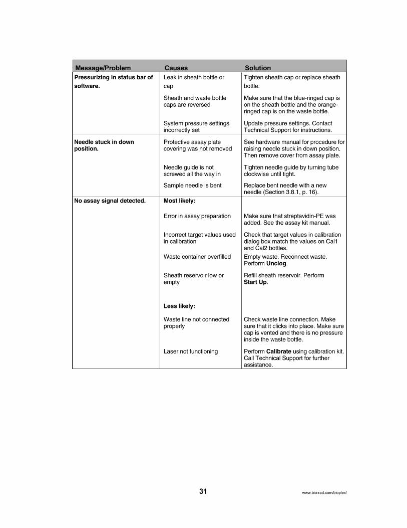
Pressurizing in status bar of Leak in sheath bottle or Tighten sheath cap or replace sheathsoftware. cap bottle.
Sheath and waste bottle Make sure that the blue-ringed cap iscaps are reversed on the sheath bottle and the orange-
ringed cap is on the waste bottle.
System pressure settings Update pressure settings. Contactincorrectly set Technical Support for instructions.
Needle stuck in down Protective assay plate See hardware manual for procedure forposition. covering was not removed raising needle stuck in down position.
Then remove cover from assay plate.
Needle guide is not Tighten needle guide by turning tubescrewed all the way in clockwise until tight.
Sample needle is bent Replace bent needle with a new needle (Section 3.8.1, p. 16).
No assay signal detected. Most likely:
Error in assay preparation Make sure that streptavidin-PE wasadded. See the assay kit manual.
Incorrect target values used Check that target values in calibrationin calibration dialog box match the values on Cal1
and Cal2 bottles.Waste container overfilled Empty waste. Reconnect waste.
Perform Unclog.
Sheath reservoir low or Refill sheath reservoir. Performempty Start Up.
Less likely:
Waste line not connected Check waste line connection. Makeproperly sure that it clicks into place. Make sure
cap is vented and there is no pressureinside the waste bottle.
Laser not functioning Perform Calibrate using calibration kit.Call Technical Support for further assistance.
31
Message/Problem Causes Solution
www.bio-rad.com/bioplex/

Bio-Plex Manager has Most likely:detected a change in sheath pressure. Sheath reservoir cap not Tighten sheath cap. Click OK.
on securely Message should disappear within 2min.
Sheath bottle lines are not Make sure that all hoses are connected connected properly to the appropriate ports, and that they
clicked into place.
Less likely:
Sheath fluid level above Adjust sheath fluid level so that sheath the AIR port on the sheath fluid is below the AIR port of sheath container bottle.
Sheath and waste bottle Make sure that the blue-ringed cap iscaps are reversed on the sheath bottle and the orange
striped cap is on the waste.
Sheath bottle has a leak Try new sheath bottle. Call technicalservice for further assistance.
HTF unit not turned on Turn on HTF unit and ensure that message disappears.
Air compressor not Listen for air pump to turn on when working Warm Up is selected. Contact
Technical Support for further assistance.
Bio-Plex Manager has Room temperature has Calibrate array reader.detected a change in the changedtemperature of the arrayreader. Please calibrate before running on assay toensure accurate results.
The calibration was Calibration procedure Make sure Cal1 beads and Cal2 unsuccessful. Please repeat failed beads are placed in the appropriate calibration. If calibration wells (Cal1 in red well and Cal2 infails a second time, consult green well). Repeat calibration. MakeTroubleshooting Guide. sure you are using a clean MCV plate.The calibration was Calibration procedure Run Unclog procedure, then repeatunsuccessful. Bio-Plex failed due to low bead calibration. If problem persists, contactManager has detected a number Technical Support. See “low beadproblem with low bead number” in troubleshooting guide.number. Please repeatcalibration.Optical Validation Problem with optical Recalibrate the array reader and thenProcedure shows value(s) component of array repeat validation procedure. If valuesoutside of acceptable reader are still out of range, contact Technicalrange(s). Support.Reporter Validation Problem with optical Recalibrate the array reader and thenProcedure shows value(s) component of reader repeat validation procedure. If valuesoutside of acceptable are still out of range, contact Technicalrange(s). Support.Classify Validation Problem with calibration Recalibrate the array reader and thenProcedure shows value(s) or optical component of repeat validation procedure. If valuesoutside of acceptable reader are still out of range, contact Technicalrange(s). Support.
32www.bio-rad.com/bioplex/
Message/Problem Causes Solution
Blue power indicator light on 1. System not plugged in Turn on system, power strip.HTF is not on 2. Power strip not on Remove power cable and reconne
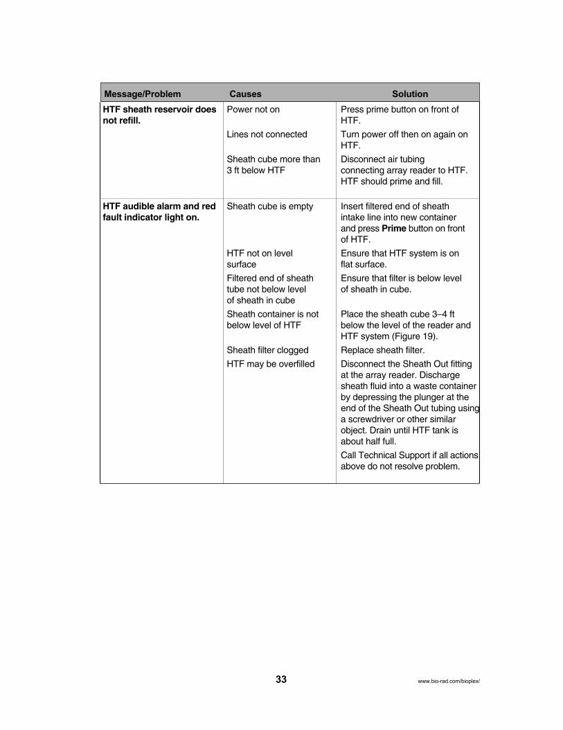
HTF sheath reservoir does Power not on Press prime button on front of not refill. HTF.
Lines not connected Turn power off then on again onHTF.
Sheath cube more than Disconnect air tubing 3 ft below HTF connecting array reader to HTF.
HTF should prime and fill.
HTF audible alarm and red Sheath cube is empty Insert filtered end of sheath fault indicator light on. intake line into new container
and press Prime button on frontof HTF.
HTF not on level Ensure that HTF system is on surface flat surface.
Filtered end of sheath Ensure that filter is below level tube not below level of sheath in cube. of sheath in cube
Sheath container is not Place the sheath cube 3–4 ftbelow level of HTF below the level of the reader and
HTF system (Figure 19).
Sheath filter clogged Replace sheath filter.
HTF may be overfilled Disconnect the Sheath Out fittingat the array reader. Dischargesheath fluid into a waste containerby depressing the plunger at theend of the Sheath Out tubing usinga screwdriver or other similarobject. Drain until HTF tank isabout half full.
Call Technical Support if all actionsabove do not resolve problem.
33
Message/Problem Causes Solution
www.bio-rad.com/bioplex/
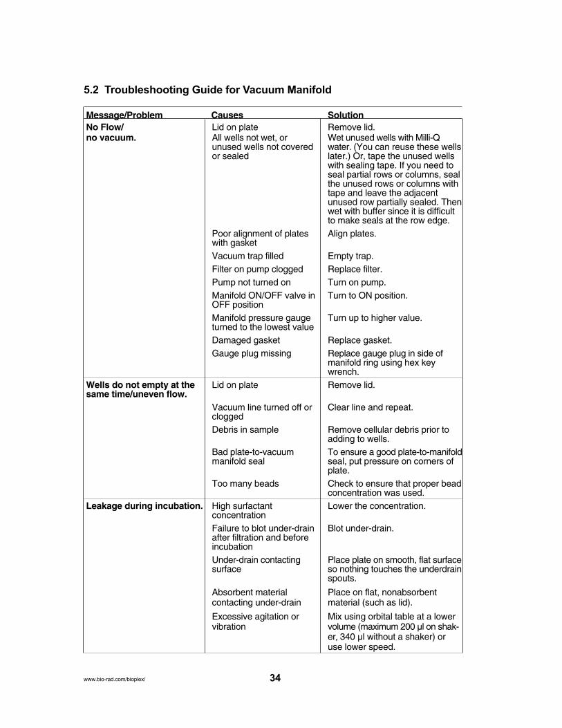
5.2 Troubleshooting Guide for Vacuum Manifold
Message/Problem Causes SolutionNo Flow/ Lid on plate Remove lid.no vacuum. All wells not wet, or Wet unused wells with Milli-Q
unused wells not covered water. (You can reuse these wellsor sealed later.) Or, tape the unused wells
with sealing tape. If you need toseal partial rows or columns, sealthe unused rows or columns withtape and leave the adjacentunused row partially sealed. Thenwet with buffer since it is difficultto make seals at the row edge.
Poor alignment of plates Align plates.with gasketVacuum trap filled Empty trap.Filter on pump clogged Replace filter.Pump not turned on Turn on pump.Manifold ON/OFF valve in Turn to ON position.OFF positionManifold pressure gauge Turn up to higher value.turned to the lowest valueDamaged gasket Replace gasket.Gauge plug missing Replace gauge plug in side of
manifold ring using hex keywrench.
Wells do not empty at the Lid on plate Remove lid.same time/uneven flow.
Vacuum line turned off or Clear line and repeat.clogged Debris in sample Remove cellular debris prior to
adding to wells.Bad plate-to-vacuum To ensure a good plate-to-manifold manifold seal seal, put pressure on corners of
plate.Too many beads Check to ensure that proper bead
concentration was used.Leakage during incubation. High surfactant Lower the concentration.
concentrationFailure to blot under-drain Blot under-drain.after filtration and beforeincubationUnder-drain contacting Place plate on smooth, flat surface surface so nothing touches the underdrain
spouts.
Absorbent material Place on flat, nonabsorbent contacting under-drain material (such as lid).
Excessive agitation or Mix using orbital table at a lower vibration volume (maximum 200 µl on shak-
er, 340 µl without a shaker) oruse lower speed.
34www.bio-rad.com/bioplex/

5.3 Technical Support
For technical assistance with the Bio-Plex 200 system, including all hardware and software,contact your local Bio-Rad office or, in the US, call 1-800-424-6723. All accessories and spareparts not listed in this document can be ordered similarly, or write to Bio-Rad Laboratories, Inc.,2000 Alfred Nobel Drive, Hercules, CA 94547.
Section 6Bio-Plex 200 System Specifications
General Technical Specifications
Environmental conditions
Operating temperature 15–30°C (59–86°F)Operating humidity 20–80%, noncondensingOperating altitude Designed to operate at 2,400 m (7,874 ft) above
mean sea level or belowCompensatory range ± 2°C
UL installation category UL Installation Category II, as defined in Annex J ofUL 3101-1
Pollution degree Pollution Degree 2, as defined in Section 3.7.3.2 ofUL 3101-1
Array Reader Specifications
Input voltage range 100–240 V, ~1.5 A, 47–63 Hz
Physical dimensions (W x D x H) 43 x 51 x 23 cm
Weight 23 kg (60 lb)
Lasers
Reporter laser 532 nm, 10 mW
Classification laser 635 nm, 8.5 mW, diode
Fluidics
Sheath flow rate 90 µl/sec
Cuvette 200 µm square flow channel
Sample injection rate 60 µl/min
Electronics
Reporter channel Photomultiplier tube, A/D resolution 14 bitsdetection
Classification and Avalanche photodiodes with temperaturedoublet discriminator compensation, A/D resolution 12 bitschannel detection
Communications interface RS232 and USB
Signal processing
Measurement resolution 15 bits effectiveProcessor modes Linear, with logarithmic or linear display optionDynamic range 70 dB
35 www.bio-rad.com/bioplex/

Microplate Platform Specifications
Input voltage range 100–240 V, ~2.25 A, 47–63 HzPhysical dimensions ((WW xx DD xx HH)) 44 x 61 x 8 cm (17.3 x 24 x 3 in)Weight 14.4 kg (32 lb)Communications interface RS232Plate capacity One 96-well microplate no thicker than
0.75 in
HTF SpecificationsInput voltage range 100–240 V, 1.8 A, 47–63 HzPhysical dimensions (W x D x H) 20 x 30 x 75 cm, (8 x 12 x 10 in)Weight 9 kg (20 lb)
Computer SpecificationsComponent Minimum Recommended
Operating system Windows 2000 or XP Windows 2000 or XP Professional
Processor Pentium III or equivalent Pentium III or higher, 1 GHz or
933 MHz higher
Hard disk space 4 GB 40 GB
System memory 256 MB 512 MB
Screen resolution 1,024 x 768 1,024 x 768
Screen colors 256 colors 24-bit True Color
Ports for 2 RS232 serial ports or 1 RS232 serial port and 1 USB port
connecting Bio-Plex 1 RS232 serial port and
instrument 1 USB port
(workstation only)
Port for connecting 1 USB port 1 USB porthardware protectionkey (software license)Other software Internet Explorer 6.0 or higher Internet Explorer 6.0 or higher
Microsoft Excel 2000 or higher Microsoft Excel 2000 or higher
36www.bio-rad.com/bioplex/

Section 7Warranty StatementThis warranty statement may vary outside of the continental United States. Please contact yourlocal Bio-Rad office for the exact terms of your warranty.
Bio-Rad Laboratories, Inc. warrants to the customer that the Bio-Plex 200 system (catalog#171-000201, 171-000203, 171-000205, and 171-000207) will be free from defects in materialsand workmanship, and will meet all performance specifications for the period of 1 year from thedate of shipment. If such defects appear within this period, the defective part(s) will be replacedor the entire unit will be replaced, at Bio-Rad’s option, free of any charges to the buyer otherthan expenses incurred in returning the unit to the factory. Bio-Rad’s obligation under this warranty is specifically limited to the aforementioned replacement or repairs. However, the following defects are specifically excluded:
1. Defects caused by improper operation.2. Repair or modification done by anyone other than Bio-Rad Laboratories, Inc. or their agent.3. Damage due to use of sheath fluid not specified by Bio-Rad Laboratories, Inc.4. Damage due to use with bead-based assay reagents not specified by Bio-Rad
Laboratories, Inc.5. Damage due to use with calibration and validation reagents not specified by Bio-Rad
Laboratories, Inc.6. Damage caused by deliberate or accidental misuse.7. Damage caused by disaster.8. Damage resulting from facility problems such as power surges.
The foregoing obligations are in lieu of all other obligations and liabilities including negligenceand all warranties, of merchantability, fitness for a particular purpose or otherwise, expressed orimplied in fact or by law, and state Bio-Rad’s entire and exclusive liability and Buyer’s exclusiveremedy for any claims or damages in connection with the furnishing of goods or parts, theirdesign, suitability for use, installation or operation, Bio-Rad will in no event be liable for anyspecial, incidental or consequential damages whatsoever, and Bio-Rad’s liability under no circumstances will exceed the contract price for the goods for which liability is claimed.
No rights or licenses under any of Luminex Corporation's patents are granted by or shall be impliedfrom the sale or acquisition of this Bio-Plex 200 system containing Luminex technology (the"System") to you, the end-user. By using this System, you agree that (i) the System is sold only foruse with fluorescently labeled microsphere beads authorized by Luminex ("Beads"), and (ii) youobtain rights under Luminex's patents to use this System by registering this System with Bio-Rad inaccordance with the instructions accompanying this System and purchasing a kit containing Beads.
Computer equipment is supplied by an independent vendor. Should you encounter any problemwith the computer equipment within 30 days, Bio-Rad will assume responsibility for replacement.Should the problem occur after 30 days, you will be covered by the normal warranty terms andwill be put in direct contact with the vendor.
37 www.bio-rad.com/bioplexsystem/

Section 8Ordering Information — System Accessories
Catalog # Description
General System Accessories
171-000050 HTF
171-000055 Sheath Fluid, 20 L
171-002001 Communication Cable, 5 ft, DB9
171-002003 Communication Cable, 5 ft, USB
171-002002 Communication Cable, 3 ft, CAN BUS
Array Reader Accessories
171-002010 Sheath Fluid Bottle, 1 L, polypropylene, includes 2 ports and tubing
171-002012 Sheath Waste Bottle, 2 L, polypropylene
171-002020 Sample Needle, 11.7 cm/4.6 in.
38www.bio-rad.com/bioplex/
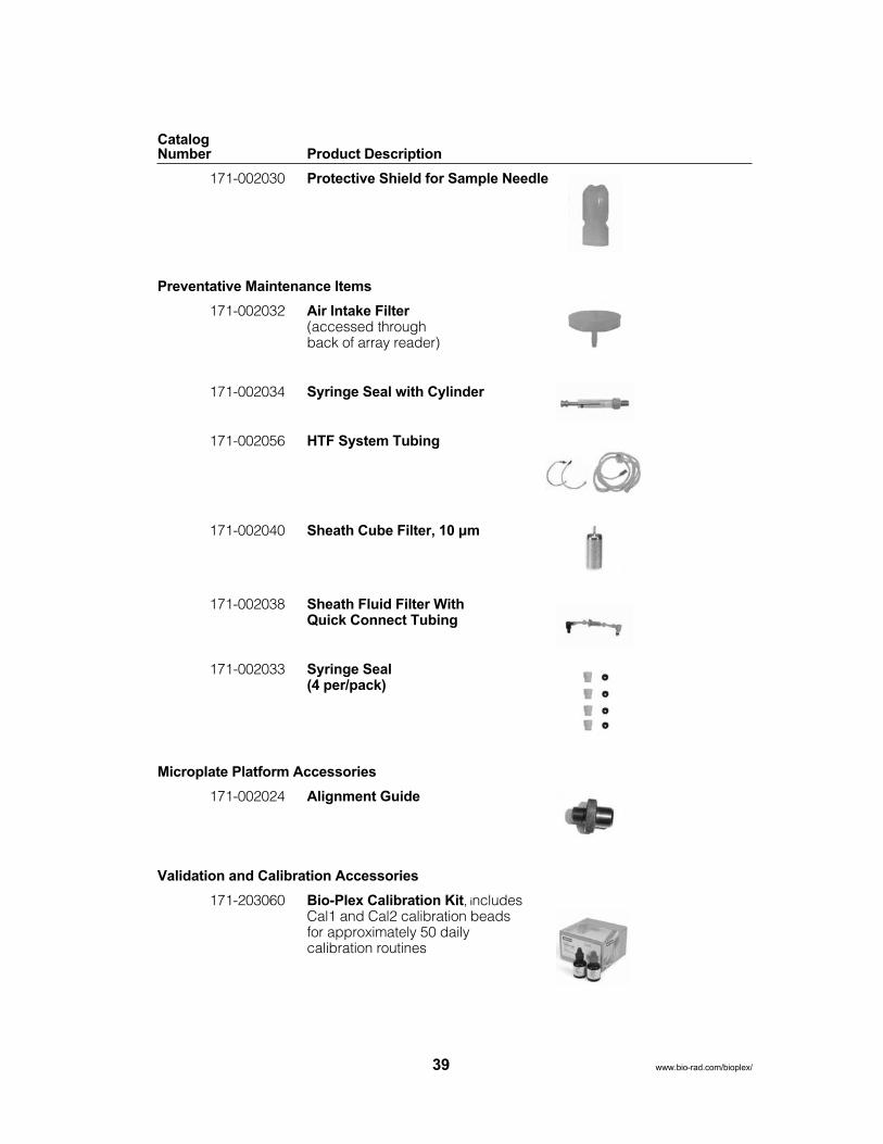
CatalogNumber Product Description
171-002030 Protective Shield for Sample Needle
Preventative Maintenance Items
171-002032 Air Intake Filter(accessed through back of array reader)
171-002034 Syringe Seal with Cylinder
171-002056 HTF System Tubing
171-002040 Sheath Cube Filter, 10 µm
171-002038 Sheath Fluid Filter With Quick Connect Tubing
171-002033 Syringe Seal(4 per/pack)
Microplate Platform Accessories
171-002024 Alignment Guide
Validation and Calibration Accessories
171-203060 Bio-Plex Calibration Kit, includes Cal1 and Cal2 calibration beads for approximately 50 daily calibration routines
39 www.bio-rad.com/bioplex/

CatalogNumber Product Description
171-203032 MCV plate III, for use with Bio-Plex Manager 4.0and 4.1 Software
171-203001 Bio-Plex Validation Kit 4.0, includes optics validation, fluidicsvalidation, reporter validation, and classify validation bead sets for approximately 50 validation routines
Section 9Decontamination InformationBefore return shipment of Bio-Plex 200 system equipment, the accessible surfaces and the internal fluidics system must be sanitized and decontaminated. Before Bio-Rad can accept thisequipment, you must certify that it is NOT CONTAMINATED with chemical, radioactive, or biological materials or hazards. Make a copy of these two pages and follow the steps below tocomplete the decontamination certification on page 42. Place the decontamination certificate in asturdy envelope and tape to the top of the corrugated shipping box.
If the equipment was used in a class 2, 3, or 4 biohazard work area, or if the equipment wasexposed to known carcinogens or teratogens, or exposed to radioisotopes other than those listedon the decontamination certificate, we will not accept it for repair. If you have any questions, contact your local Bio-Rad office or, in the US, call 1-800-4BIO-RAD.
The following checklist is provided for your convenience. Please complete and return with thesigned decontamination form.
1. Replace the fluid in the sheath bottle with a solution of 10% household bleach and DI water.Fill the 10% bleach reservoir of the MCV plate with 10% bleach. Fill the DI H2O reservoir ofthe MCV plate with distilled water and place the MCV plate in the microplate platform.
2. Turn on the reader and microplate platform. Open Bio-Plex Manager software. SelectInstrument, select Shut down.
3. When Shut down is complete, close Bio-Plex Manager software and turn off the power tothe array reader and microplate platform. Disconnect the instrument from AC power byturning off the power switch on the rear of the instrument. Unplug the instrument power cordfrom the wall source.
4. Disconnect the sheath fluid and waste containers.
5. Drain the sheath fluid and waste containers.
6. Rinse the waste container with 10% household bleach solution and drain.
7. Remove all specimens, disposables, and reagents from the instrument.
8. Wash all exterior surfaces with a mild germicidal detergent, followed by a 10% bleach solution.
9. Open both front doors of the instrument and clean all accessible surfaces with detergentfollowed by a 10% bleach solution.
Any issues related to decontamination or aerosolization are available separately. Contact Bio-Rad Technical Support.
40www.bio-rad.com/bioplex/
Section 10Legal NoticesTrademarks
xMAP is a trademark of Luminex Corporation. The Bio-Plex suspension array system includesfluorescently labeled microspheres and instrumentation licensed to Bio-Rad Laboratories, Inc.by the Luminex Corp.
Cheminert is a trademark of Valco Instruments Co., Inc.
HASP is a trademark of Aladdin Knowledge Systems Ltd.
Millipore and Milli-Q are trademarks of Millipore Corporation.
Pentium is a trademark of Intel Corporation.
Teflon is a trademark of E.I. duPont de Nemours & Co.
Windows 2000, XP, XP Professional, Excel, and Internet Explorer are trademarks of MicrosoftCorporation.
41 www.bio-rad.com/bioplex/

Equipment Return Information Label andDECONTAMINATION CERTIFICATE
Before Bio-Rad can accept this equipment, you must certify that it is NOT CONTAMINATED withchemical, radioactive, or biological materials or hazards. Please indicate if any of the following potential hazards may have come in contact with the equipment, and the steps you have taken todecontaminate the equipment by marking the appropriate box (❏).
If the equipment was used in a class 2, 3, or 4 biohazard work area, or if the equipment was exposedto known carcinogens or teratogens, or exposed to radioisotopes other than those listed below, we willnot accept it for repair in-house. If you need service for such instruments, or if you have any questions, please call 1-800-4BIO-RAD.
1. Chemicals❏ Strong acids or bases (names and concentrations)❏ Solvent(s) (name)❏ Other❏ No hazardous chemicals came in contact with this equipment.
2. Radioactive Materials (Have any of the following isotopes been used with the equipment?)❏ P32 ❏ I 125 ❏ S 35 ❏ C 14 H 3 ❏ N 15❏ Other isotopes
If so, were these: ❏ Beta emitters ❏ Gamma emitters ❏ Alpha emittersEquipment has been surveyed by (method) prior to shipment.
Reading❏ No radioactive materials came in contact with this equipment.
3. Biological Hazards (Are any of the following applicable to this equipment?)❏ The equipment contained live microorganisms (for example, bacteria) or live virus.❏ The equipment contained live bacteria other than E. coli.
If so, name of bacteria:❏ Equipment was used in a class 2, 3, or 4 biohazard work area. (We will not accept it forrepair. Please call to make other arrangements.)❏ The equipment contained or was exposed to blood, serum, blood products, or otherbodily fluids.❏ No biological hazards have come in contact with this equipment.
4. Decontamination This equipment has been decontaminated with:
5. ❏ This instrument has never been used and is in new condition.
I certify that this instrument has been cleaned and decontaminated of any chemical, radioactive, or biological materials or hazards that may have come in contact with the equipment during the equipment’s use and operation.
Signed Title
Date Printed Name
Institution Phone
Address Fax
42

Life ScienceGroup
00-0000 0000 Sig 1106Bulletin 0000 US/EG Rev A
Bio-Rad Laboratories, Inc.
Web site www.bio-rad.com USA 800 4BIORAD Australia 61 02 9914 2800 Austria 01 877 89 01 Belgium 09 385 55 11 Brazil 55 21 3237 9400 Canada 905 712 2771 China 86 21 6426 0808 Czech Republic 420 241 430 532 Denmark 44 52 10 00 Finland 09 804 22 00 France 01 47 95 69 65 Germany 089 318 84 0 Greece 30 210 777 4396 Hong Kong 852 2789 3300 Hungary 36 1 455 8800 India 91 124 4029300 Israel 03 963 6050 Italy 39 02 216091 Japan 03 5811 6270 Korea 82 2 3473 4460 Mexico 52 555 488 7670 The Netherlands 0318 540666 New Zealand 0508 805 500 Norway 23 38 41 30 Poland 48 22 331 99 99 Portugal 351 21 472 7700 Russia 7 495 721 14 04 Singapore 65 6415 3188 South Africa 27 861 246 723 Spain 34 91 590 5200 Sweden 08 555 12700 Switzerland 061 717 95 55 Taiwan 886 2 2578 7189 United Kingdom 020 8328 2000
10005042 Rev B