bio-inspired polymer nanocomposites for tissue engineering
TRANSCRIPT

BIO-INSPIRED POLYMER NANOCOMPOSITES FOR TISSUE ENGINEERING APPLICATIONS
A Dissertation Presented to
The Academic Faculty
By
Parisa Pooyan
In Partial Fulfillment Of the Requirements for the Degree
Doctor of Philosophy in the George W. Woodruff School of Mechanical Engineering
Georgia Institute of Technology
May 2014
Copyright © 2014 PARISA POOYAN

ii
BIO-INSPIRED POLYMER NANOCOMPOSITES FOR TISSUE ENGINEERING APPLICATIONS
Date Approved: March 26, 2014
Approved by: Dr. Hamid Garmestani, Thesis Advisor School of Materials Science and Engineering Georgia Institute of Technology
Dr. Karl Jacob, ME Advisor G.W. Woodruff School of Mechanical Engineering Georgia Institute of Technology
Dr. Cyrus Aidun G.W. Woodruff School of Mechanical Engineering Georgia Institute of Technology
Dr. Luke Brewster Division of Vascular Surgery Department of Surgery Emory University School of Medicine
Dr. David McDowell G.W. Woodruff School of Mechanical Engineering Georgia Institute of Technology
Dr. Rina Tannenbaum School of Materials Science and Engineering Stony Brook University
Dr. Maziar Zafari Chief of Cardiology Division of Cardiology Emory University School of Medicine

iii
To the wind beneath my wings Mehran and Jafar
for their endless love, support, and inspiration

iv
ACKNOWLEDGEMENTS
The rewarding journey of graduate school reflects on the support of many people
without which this work would not have been possible. First and foremost, I would like
to specially thank my research adviser, Dr. Hamid Garmestani. I had the privilege to
work with him, and without his invaluable support and guidance from the very first day;
the realization of this work undoubtedly could not have been possible. I am also deeply
grateful to him for giving me the freedom to pursue my academic interests and for setting
an example of hard work and constant efforts to achieve perfection.
I would like to sincerely extend my appreciation to my committee members— Dr.
Cyrus Aidun, Dr. Luke Brewster, Dr. Karl Jacob, Dr. David McDowell, Dr. Rina
Tannenbaum, and Dr. Maziar Zafari—for taking the time to serve on my dissertation
committee, and for providing valuable research advice and insightful comments to
improve this work. A very special thanks is directed to Dr. Tannenbaum for her
outstanding help and support throughout the completion of this dissertation. Her
invaluable insights from the very beginning have directly influenced the progress of this
research. I would also like to thank my academic advisor, Dr. Jacob for his continuous
support and guidance during the completion of this work. Grateful appreciation is also
extended to Dr. Brewster and his team, especially Ms. Haiyan Li, at Emory School of
Medicine Vascular Surgery Division, for their tremendous help on the biocompatibility
study, without which the project could not have moved towards the intended
bioapplication.

v
The Institute of Paper Science and Technology at Georgia Tech is gratefully
acknowledged for funding this project by granting me a four-year Graduate Fellowship
Award. Also, I would like to sincerely acknowledge the members of the TMS Biological
Materials Science Symposium Award; the TMS Graduate Student Award Committee;
and judges for the Georgia Tech GTRIC Award for recognizing my accomplishments as
a Ph.D. student. A special note of acknowledgment is also directed to the Georgia Tech
Dean of College of Engineering, Dr. Gary May, for his very kind and inspiring letter of
recognition on my TMS Awards. The research presentation of my dissertation work at
major materials science and biomedical conferences and workshops was made possible
through generous financial support that I have received from The National Science
Foundation; The Minerals, Metals and Materials Society; Regenerative Medicine
Workshop; Nano Today Conference; and Georgia Institute of Technology.
I would also like to acknowledge Dr. David Rush, Dr. Valerie Toniazzo, and Dr.
Fatima Hassouna at CRP Henri Tudor’s Department of Advanced Materials in
Luxembourg for granting me a summer European Fellowship Award to extend my
studies on the behavior of hydrogel materials. Also, a special thanks goes to Ms. Claire
Arnoult for her valuable help with environmental scanning electron microscopy.
I would also like to thank my past and present lab mates at the Laboratory of
Micromechanics of Materials and the Laboratory of Complex Nanomaterial and Polymer
Interface. I would like to specially thank Dr. Il Tae Kim and Dr. Lex Nunnary for their
training and well-needed help on working in a chemistry lab for the very first time.
A special note of appreciation is expressed to Dr. Wayne Whiteman for his
constant help and support throughout my doctorate journey at ME. The door of his office

vi
has always been open with his kind smile and very supportive attitude to smooth your
ride all along. I would also like to sincerely acknowledge and thank Ms. Glenda Johnson
for her continued support all these years to make my ME journey a more pleasant
experience.
A very special acknowledgement is also directed to Dr. Phillip Miller for his
significant role and invaluable mentorship in my scientific life since the very early days
of my relocation to the states.
Dear friends, Ms. Layli Amoozegar, Ms. Forough Beik, Dr. Sima Didari, Ms.
Sepideh Dolatshahi, Mr. Mohammad Ilbeigi, Dr. Laura Jacob, Dr. Shahram Kavianpour,
Dr. Mohammad Reza Massoomi, Ms. Armina Raufi, Ms. Roya Rezaee, Ms. Tina
Rezvani, Dr. Reza Rezvani, Dr. Shannon Statham, and Mr. Toomaj Zakeri, I am truly
grateful for your amazing friendship and the special moments that we have shared. Thank
you for enduring this long process with me, always offering support and love. The list of
people who have touched my life with their beautiful friendship is long, and I am sure I
have forgotten many more, so I simply thank you all!
I would also like to extend my very special acknowledgment to my best friend,
Ms. Layli Amoozergar, for being a remarkable sister as one could wish for! Your endless
support and true companionship have always been a treasure over almost two decades of
our friendship. I cherish every second of your exquisite friendship and thank you for
being there for me in each step of the way throughout this chapter of life.
A special thanks is also addressed to my dear AE and ME friends, Ms. Tina
Rezvani and Dr. Sima Didari, for their endless support throughout riding the roller

vii
coaster of graduate school. Their companionship all the way has given me the joy to keep
moving forward.
A special feeling of appreciation is extended to my loving brother, Dr. Payam
Pooyan, who has never left my side with his constant encouragement and continuous
support throughout this journey. My gratitude to you is beyond words. I would also like
to specially thank my sister-in-law, Dr. Bita Shakoory, for her loving support from the
very beginning of my relocation to the States. A very special thanks is also directed to my
adorable nephew, Mr. Pendaar Pooyan, for touching my life with his beauty and for
adding joy into my every day. You are simply my little sunshine!
A very special feeling of gratitude is also expressed to my beautiful aunt, Ms. Giti
Kerachi, for the countless occasions that I received her love and support. Your
compassionate character has always been a true source of motivation and encouragement
over the course of my doctorate journey.
Last but for no means least, this dissertation work is specially dedicated to the
center of my universe, my heroes: Mehran and Jafar. Needless to mention, I could not
have moved along this journey and be the person I am today without your impeccable
role, your endless sacrifice, and your unconditional love. Thank for believing in me in
each step of the way; thank you for giving me the strength to fly high against the sky; and
thank you for letting me ride the wind to the land of my dream.

viii
TABLE OF CONTENTS
ACKNOWLEDGEMENTS ........................................................................................... iv LIST OF TABLES ............................................................................................................ x LIST OF FIGURES ......................................................................................................... xi NOMENCLATURE ........................................................................................................ xv SUMMARY ................................................................................................................... xvii Chapter 1: Background and Motivation for the Study ................................................. 1 1.1 Biologically inspired Materials ........................................................................... 1 1.2 Example Application of a Bio-inspired Material: Scaffolding in Tissue
Engineering ........................................................................................................ 2 1.3 Bio-inspired Nanomaterial .................................................................................. 4 1.4 Bio-inspired Carbohydrate-based Nanocomposite ............................................. 7 1.5 Bio-inspired Protein-based Nanocomposite ....................................................... 8 1.6 Thesis Organization .......................................................................................... 11 Chapter 2: Experimental Procedures ........................................................................... 14 2.1 Material Processing ........................................................................................... 14
2.1.1 Preparation of Cellulose Nanowhiskers (CNWs) ..................................... 14 2.1.2 Preparation of a Carbohydrate-based Nanocomposite Reinforced with
CNWs ....................................................................................................... 16 2.1.3 Preparation of a Protein-based Nanocomposite Reinforced with CNWs . 18
2.2 Material Characterization .................................................................................. 19 2.2.1 Microstructure Microscopy ...................................................................... 20 2.2.2 Mechanical Testing .................................................................................. 21 2.2.3 Thermal Testing ........................................................................................ 23 2.2.4 Bicompatibility Study ............................................................................... 25
CHAPTER 3: Fabrication of Cellulose Nanowhiskers ............................................... 27 3.1 Fabrication of Cellulose Nanowhisker .............................................................. 27 3.2 Characterization of Cellulose Nanowhisker ..................................................... 27
3.2.1 CNW Morphology and Topography ......................................................... 28 3.2.2 CNW Colloidal Suspension ...................................................................... 30 3.2.3 CNW Dispersion ....................................................................................... 31
3.3 Summary and Future Directions ....................................................................... 34 Chapter 4: Fabrication of a Bio-inspired Carbohydrate-based Nanocomposite Reinforced with CNWs .................................................................................................. 35

ix
4.1 Fabrication of Cellulose Acetate Propionate- Cellulose Nanowhisker Composite ......................................................................................................................... 35 4.2 Characterization of Cellulose Acetate Propionate- Cellulose Nanowhisker Composite ......................................................................................................................... 36
4.2.1 Microstructure of the CAP-CNW Composite ........................................... 36 4.2.2 Mechanical Properties of the CAP -CNW Composite .............................. 42 4.2.2.1 Experimental Tensile Tests ................................................ 42 4.2.2.2 Theoretical Mechanical Modeling ..................................... 48 4.2.3 Thermal Properties of the CAP-CNW Composite .................................... 62
4.3 Summary and Future Directions ....................................................................... 67 Chapter 5: Fabrication of a Bio-inspired Protein-based Nanocomposite Reinforced with CNWs ....................................................................................................................... 69 5.1 Fabrication of Collagen- Cellulose Nanowhisker Composite .......................... 69 5.2 Characterization of Collagen - Cellulose Nanowhisker Composite ................. 70
5.2.1 Microstructure of the COL-CNW Composite ........................................... 70 5.2.2 Mechanical Properties of the COL-CNW Composite .............................. 73 5.2.2.1 Oscillatory Strain Sweep .................................................... 74 5.2.2.2 Oscillatory Time Sweep ..................................................... 80 5.2.2.3 Oscillatory Frequency Sweep ............................................ 82 5.2.3 Thermal Properties of the COL-CNW Composite .................................... 87
5.3 Summary and Future Directions ....................................................................... 91 Chapter 6: Biocompability Study .................................................................................. 93 6.1 Cell Culture Method ......................................................................................... 93 6.2 Cell Growth on the Collagen- Cellulose Nanowhisker Composite .................. 94 Chapter 7: Concluding Remarks and Directions ......................................................... 98 7.1 Concluding Remarks ......................................................................................... 98 7.2 Future Directions ............................................................................................ 100 REFERENCES

x
LIST OF TABLES
Table 1.1: Mechanical properties of the nano-sized cellulose whiskers compared with other filler agents .............................................................................................. 6
Table 4.1: Results from tensile measurements for samples prepared by different
processing methods and for samples having various nanowhisker concentrations ................................................................................................ 46
Table 4.2: DSC and TGA measurements of the thermal properties for the CAP-CNW
composite samples with 0.2 wt.% CNW and prepared by different processing methods, and for samples with different nanowhisker concentrations taking the pre-dispersed fabrication protocol ............................................................ 66
Table 5.1: Oscillatory stain sweep data of the pure collagen compared to the collagen-
cellulose hydrogel nanocomposite at 1, 3, 6, and 9 wt.% CNW under constant ω =0.1 rad/s while deforming the hydrogels within the linear viscoelastic region at room temperature ............................................................................ 80
Table 5.2: DSC and TGA measurements of the thermal properties for the pure collagen
and the COL-CNW composites with 1, 3, 6, 9% by weight of nanowhiskers, which were prepared by the pre-dispersed and the freeze-dried fabrication protocol ........................................................................................................... 90

xi
LIST OF FIGURES
Figure 1.1: Schematic representation of scaffold morphologies and their impact on cell anchoring, adhesion and proliferation .............................................................. 3
Figure 1.2: A strand of cellulose, representing the linear chains of cellulose molecules
inter-linked through hydrogen bonds to form a 3D rigid network ................... 5 Figure 2.1: The suspension of cellulose nanowhiskers subjected to sulfuric acid
hydrolysis ........................................................................................................ 15 Figure 2.2: Freeze-dried cellulose nanowhiskers directly from the freeze-dryer and
measured by weight prior to mixing with the biopolymer matrix and forming the nanocomposites of CAP-CNW and COL-CNW ....................................... 16
Figure 2.3: Chemical structure of cellulose acetate propionate ....................................... 16 Figure 2.4: Schematic representation of the alignment of CNWs within the CAP matrix
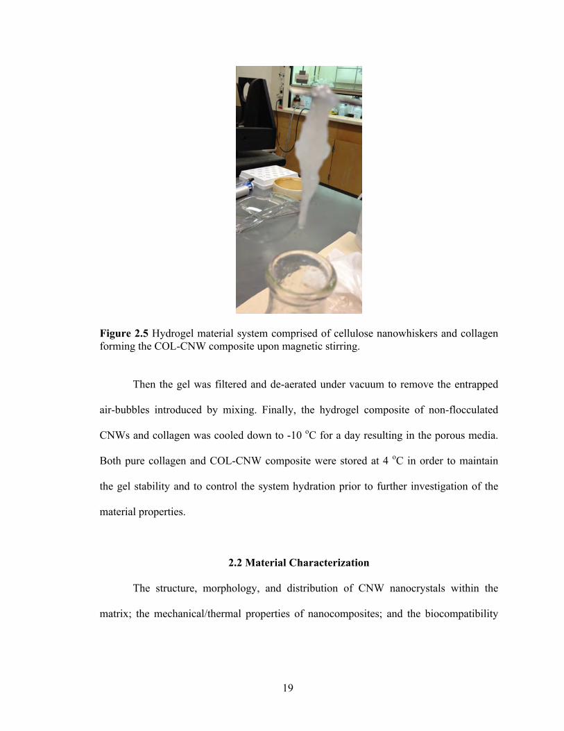
under an externally applied magnetic field .................................................... 18 Figure 2.5: Hydrogel material system comprised of cellulose nanowhiskers and collagen
forming the COL-CNW composite upon magnetic stirring ........................... 19 Figure 3.1: (A) AFM images of the morphology of cellulose nanowhiskers that were
obtained by drying their aqueous suspension. (B) Higher resolution AFM images of the cellulose nanowhiskers, depicting in more intimate detail the interactions among them in an aqueous solution ............................................ 29
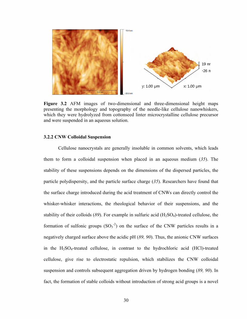
Figure 3.2: AFM images of two-dimensional and three-dimensional height maps
presenting the morphology and topography of the needle-like cellulose nanowhiskers, which they were hydrolyzed from cottonseed linter microcrystalline cellulose precursor and were suspended in an aqueous solution ........................................................................................................... 30
Figure 3.3: SEM images of the aggregation of cellulose nanowhiskers in form of stable
colloidal suspension in an aqueous solution at different magnifications ......................................................................................................................... 31
Figure 3.4: Transmission electron micrograph from a freeze-dried/pre-dispersed sample
of cellulose nanowhiskers ............................................................................... 33 Figure 3.5: TEM image of the freeze-dried and pre-dispersed cellulose nanowhiskers in
acetone prior to the fabrication of the nanocomposite materials .................... 33

xii
Figure 4.1: SEM images of the dispersion of CNWs within the CAP medium at 3% by weight at two different magnifications ........................................................... 37
Figure 4.2: Cross-sectional SEM images of the fibrous architecture of CAP-CNW
composites at 0.2% by weight of nanofiller concentration at two different magnifications ................................................................................................ 38
Figure 4.3: SEM images of the macroporous CAP-CNW composites at: (A) 0.2% by
weight and (B) 9% by weight of nanofiller concentrations ............................... ......................................................................................................................... 39
Figure 4.4: SEM images of the CAP-CNW composite, illustrating the porous structure of
the biomaterial with 0.2% weight of nanowhiskers at two different magnifications ................................................................................................ 40
Figure 4.5: SEM images of CAP-CNW composites containing 0.2% by weight of
nanowhiskers: (A) a non-oriented microstructure and (B) an oriented morphology resulting from exposure to a homogenous magnetic field of 0.3T ......................................................................................................................... 41
Figure 4.6: SEM images of a cross-section of the magnetically aligned CAP-CNW
composite containing 0.2 wt.% cellulose nanowhiskers at two different magnification, A (x1000) and B (x10000) where H represents the direction of the magnetic field ........................................................................................... 41
Figure 4.7: True stress vs. true strain curves of the CAP-CNW composites obtained from
classical tensile tests at body temperature (37 oC). (A) For different processing techniques at a fixed 0.2 wt.% CNWs (B) at different whisker volume fractions using the pre-dispersed technique (method 2) .................... 45
Figure 4.8: Comparison in the elastic moduli of the CAP-CNW composites for samples
containing 0.2 and 3% by weight of nanowhiskers that were either isotropic or aligned under an externally-applied magnetic field ....................................... 47
Figure 4.9: Schematic representation of the series-parallel model for a CNW-based
composite with ψ indicating the volume fraction of the percolating nanofiller phase; cellulose nanowhiskers ....................................................................... 53
Figure 4.10: The experimental vs. the predicted effective modulus from three different
homogenization schemes with the fiber aspect ratio of f=60 ........................ 56 Figure 4.11: The comparison of the theoretical models at different ranges of CNW aspect
ratios (A) Halpin-Kardos (B) Percolation ...................................................... 60

xiii
Figure 4.12: Stress-strain behavior of the CAP-CNW composite by 3% weight of nanowhiskers was compared with that of natural connective tissues: tendon, ligament, and cornea ....................................................................................... 62
Figure 4.13: TGA thermograms of the CAP-CNW composites for: (A) Samples prepared
by different processing protocols at a fixed 0.2% by weight of CNW, and (B) Samples with different nanowhisker concentrations using the pre-dispersed processing method ......................................................................................... 65
Figure 5.1: SEM micrographs presenting the effect of processing methods in the
microstructure of the fabricated cellulose-collagen hydrogel nanocomposite at 3 wt.% nanofiller: (A) at room temperature with no microporous landscape (B) Porous induced microstructure upon the hydrogel freeze-drying ......................................................................................................................... 71
Figure 5.2: SEM micrographs showing the fibrous nature of the fabricated collagen-
cellulose hydrogel nanocomposite at 3% by weight of CNWs forming a three-dimensional percolating network at different magnifications ......................................................................................................................... 72
Figure 5.3: Frequency dependence of elastic shear modulus in an oscillatory strain sweep
to obtain the linear viscoelastic region (LVR) of: (A) Pure collagen (B) COL-CNW composite at 3wt.% nanowhisker ........................................................ 76
Figure 5.4: Linear versus nonlinear behavior of the neat collagen and collagen-CNW
hydrogel composite at 3wt.% nanofiller in an oscillatory strain sweep where the elastic (G') modulus and applied shear stress (τ) were plotted versus shear strain at angular frequency of ω =0.1 rad/s at room temperature ......................................................................................................................... 78
Figure 5.5: Stress versus strain curve of the neat collagen and COL-CNW hydrogel
composite at different weight of 1, 3, 6, and 9% CNW obtained from an oscillatory strain-sweep subjected to constant angular frequency of ω =0.1 rad/s at an ambient temperature of 25 oC ........................................................ 79
Figure 5.6: Time dependence of viscosity and shear rate of the pure collagen and the
collagen-cellulose hydrogel nanocomposite at 3wt.% nanowhisker in an oscillatory time sweep. Complex viscosity (η) and shear rate (𝛾) were plotted versus time subjected to constant strain amplitude γ < 10 % and angular frequency ω =0.1 rad/s at room temperature while deforming the materials within the linear viscoelastic region .............................................................. 82
Figure 5.7: Frequency dependence of shear moduli and viscosity of the pure collagen and
the COL-CNW composite at 3wt.% nanowhisker in an oscillatory frequency sweep. Elastic modulus (G'), viscous modulus (G'') and complex viscosity (η)

xiv
were plotted versus angular frequency (ω) under constant strain amplitude of γ < 10 % within the hydrogel linear viscoelastic region ................................... 84
Figure 5.8: The comparison of Frequency dependence of shear moduli of the pure
collagen and the COL-CNW composite at 1, 3, 6, and 9 wt.% nanowhisker in an oscillatory frequency sweep. Elastic modulus (G') and viscous modulus (G'') were plotted versus angular frequency (ω) under constant strain amplitude of γ < 10 % within the hydrogel linear viscoelastic region ......................................................................................................................... 85
Figure 5.9: The comparison of shear moduli in the COL-CNW composite at 3wt.%
nanowhisker with that of the bovine orbital connective tissue subjected to an oscillatory frequency sweep. The elastic (G') and viscous (G'') moduli were plotted versus angular frequency (ω) under constant strain amplitude of γ < 10 % inside the nanocomposite linear viscoelastic region ............................. 86
Figure 5.10: TGA thermograms representing the thermal decomposition and the
formation of gaseous reaction products of the freeze-dried cellulose nanowhiskers, the pure collagen, and the COL-CNW hydrogel composite ......................................................................................................................... 90
Figure 6.1 Digital optical microscope images of the three-dimensional COL-CNW
sandwich assay with the radial invasion of MSCs between the hydrogel material and the nylon ring at day 8 of the in-vitro culture at 4x magnification......................................................................................................................... 94
Figure 6.2: Phase-contrast/ bright-field images of the in-vitro culture of MSCs at 10x
magnification showing: (A) the sprout of cells from bundle-like aggregates at day 1 (B) the radial expansion around the COL-CNW composite at day 8 ......................................................................................................................... 95
Figure 6.3: Phase-contrast microscopy image showing the outgrowth of MSCs from their
proliferation sites and spreading around the fabricated collagen-cellulose hydrogel nanocomposite (3 wt.% nanowhiskers) after an in-vitro culture for 8 days at 10x magnification .............................................................................. 96
Figure 6.4: The density increase of the encapsulated MSC nuclei around the COL-CNW
composite spreading in day 8 (Right image) in contrast to that of in day 1 (Left image). The images were taken by DAPI-DNA staining at 10x magnification ................................................................................................. 97

xv
NOMENCLATURE
AFM Atomic Force Microscopy
Bio-inspired Biologically inspired
CAP Cellulose Acetate Propionate
CAP-CNW Cellulose acetate propionate -Cellulose film nanocomposite
CNW Cellulose Nanowhisker
COL Collagen hydrogel
COL-CNW Collagen -Cellulose hydrogel nanocomposite
CNW Cellulose Nanowhisker
d Fiber diameter
DSC Differential Scanning Calorimetry
Em Elastic Young's modulus of matrix
Ef Elastic Young's modulus of filler
E11 Elastic Young's modulus in the longitudinal direction of fibers
E22 Elastic Young's modulus in the transverse direction of fibers
η Complex viscosity
ECM Extracellular Matrix
f Fiber aspect ratio
Gm Elastic shear modulus of matrix
Gf Elastic shear modulus of filler
G' Storage shear modulus, Elastic modulus
G" Loss shear modulus, Viscous modulus

xvi
γ Shear strain
𝛾 Shear strain rate
LVR Linear Viscoelastic Region
L Fiber length
MSC Human derived Mesenchymal Stem Cell
𝜈 Poisson’s rtio
ψ Volume fraction of the percolating nanofiller phase
SEM Scanning Electron Microscopy
η Complex viscosity
τ Oscillatory shear stress
T Tesla
Tg Glass transition temperature
Tm Melting temperature
TGA Thermogravimetric Analysis
TEM Transmission Electron Microscopy
Vf Volume fraction of fibers
Vm Volume fraction of the matrix
ω Angular frequency
wt.% Percentage by weight of fibers
xvii
SUMMARY Increasing emphasis has been placed on the use of renewable resources, on
decreased reliance on petroleum in order to better utilize global energy needs. Biological
structures available in nature have been a constant inspiration to the design and
fabrication of the new line of functional biomaterials whose unique phenomena can be
exploited in novel applications. In tissue engineering for example, a natural biomimetic
material with close resemblance to the profile features existed in a native extracellular
matrix could provide a temporary functional platform to regulate and control cellular
interactions at a molecular level and to subsequently direct a tissue regeneration.
However, the lack of rigidity of natural materials typically limits their mass production.
One promising approach to address this shortcoming is to introduce a biomimetic
composite material reinforced by high purity nanofibers found in nature. As an attractive
reinforcing filler phase, cellulose nanowhiskers (CNWs) offer exceptional properties such
as high aspect ratio, large interface area, and significant mechanical integrity. As such,
CNWs could integrate a viable nanofibrous porous candidate, resulting in superior
structural diversity and functional versatility. Inspired by the fascinating properties of
cellulose and its derivatives, we have designed two bio-inspired nanocomposite materials
reinforced with CNWs in this work.
In our first design, a bio-inspired carbohydrate-based nanocomposite was
fabricated such that the CNWs were well dispersed and embedded in a matrix of cellulose
acetate propionate (CAP-CNW composite). The dispersed CNW phase created a rigid
network within the host matrix, which imparted considerable mechanical strength and

xviii
thermal stability to the entire composite system at only 0.2 wt.%, and substantially
enhanced these properties upon the orientation of the nanowhiskers. The aligned features
not only improved the directionality of nanoparticles within the medium, but also
drastically lowered the optimum amount of CNWs required (3 wt.%) to obtain the best
composite performance. Likewise, homogenization schemes such as the mean field
approach and the percolation technique were investigated to ensure the accuracy of our
experimental data and to predict the unusual reinforcing effect of CNWs in a cellulose-
based nanocomposite. Based on these comparisons, the tendency of CNWs to
interconnect with one another through strong hydrogen bonding gave rise to the
formation of a three-dimensional rigid percolating network, fact which imparted excellent
mechanical strength and thermal stability to the entire structure at such low filler content.
In our second design, a bio-inspired protein-based nanocomposite comprised of
collagen and cellulose nanowhiskers (COL-CNW composite) was fabricated to contrast
with our original design by resembling the structural features of natural human ECM
while delivering an effective viscoelastic behavior to the designed substrate. The most
significant aspect of the second design was reflected on fabricating a comparable series
of hydrogels and characterizing them structurally, mechanically, and thermally, which
resulted in significant property improvements at small amount of filler content, i.e. 3% by
weight. The excellent performance at such low filler content was mainly believed to be
due to the formation of the percolating filler network from hydrogen bonds between the
cellulose as well as to strong interactions between CNW surface and the polymer chains
in the collagenous medium.

xix
Finally, the initial biocompatibility of the COL-CNW composite was probed by
in-vitro incubation of human-bone-marrow-derived mesenchymal stem cells (MSCs),
which resulted in the invasion and proliferation of MSCs around the nanocomposite at
day 8 of culture. We believe that our biomimetically-engineered platform in this study,
with an oriented microstructure and tunable mechanical/ thermal properties, could open
new perspectives in the self-assembly of nanobiomaterial for tissue-engineered
scaffolding, while it could make the design of the next generation of fully green
functional biomaterial a reality.

1
CHAPTER 1
BACKGROUND AND MOTIVATION FOR THE STUDY
This chapter gives background information relevant to the current investigation.
A discussion of the biologically inspired (bio-inspired) material phenomena is followed
by an example application with its relevant design criteria. Then, three bio-inspired
material systems are introduced including cellulose nanowhiskers, carbohydrate-based
nanocomposite and protein-based nanocomposite. Finally, the potential advantages of
these bio-inspired systems for the intended application are explored in the framework of
the influential factors on the functional responses of these materials.
1.1 Biologically Inspired Materials
Nature offers a wide range of materials with structural diversity and functional
versatility that are superior to any man-made designs existing today (1, 2). Learning from
these biological structures and understanding their mechanism of self-organization can
provide a valuable scientific and technical blueprint for the design of a new class of
advanced functional bio-inspired and bio-based materials with low environmental impact
(3-6). Recent advances in nanotechnology have facilitated a higher degree of control over
the intimate features of such bio-based materials and thus, opened the door to the design
of smart adaptive biomaterials with nano-structured features (7, 8) and to their potential
use in a variety of biomedical applications (9).

2
1.2 Example Application of a Bio-inspired Material: Scaffolding in Tissue
Engineering
One of the most promising applications, and the motivating factor for the material
development in this study, is the use of green bio-inspired materials to develop substitutes
for damaged tissues or organs that are functional and closely resemble the native
morphology and physiology. Achieving such a goal to culture cells and to engineer the
tissue and subsequently the organ would benefit from the availability of a versatile bio-
scaffold that would deliver a wide range of functionalities at the cellular level, and would
thus promote new tissue formation (10). Such a bio-scaffold as an artificial extracellular
matrix (ECM) plays a significant role in integrating the overall tissue structure and thus
should offer complete biocompatibility (11), controlled porosity (12, 13), three
dimensional versatility (14, 15), surface adhesion capability (16-18) and controlled
biodegradability (11).
As a result, the surface morphology and the bulk topology of such material would
have a leading role in the successful functioning of an ECM scaffold by creating an
attractive substrate for subsequent cellular activities (9, 19). The traditional design of an
ECM scaffold has mainly focused on the properties of the biomimetic materials at the
macroscopic and microscopic levels, as shown in Figure 1.1 A and B (18, 20). New
developments in bio- and nano-technology in recent years, however, revealed the role of
nano-sized moieties in a human ECM and the crucial presence of a nano-structured bio-
scaffold as a necessary component for correct tissue development (9, 18). As such, the
nano-fibrous assemblies shown in Figure 1.1 C have a beneficial impact on guiding the
3
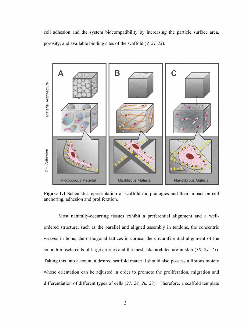
cell adhesion and the system biocompatibility by increasing the particle surface area,
porosity, and available binding sites of the scaffold (9, 21-23).
Figure 1.1 Schematic representation of scaffold morphologies and their impact on cell anchoring, adhesion and proliferation.
Most naturally-occurring tissues exhibit a preferential alignment and a well-
ordered structure, such as the parallel and aligned assembly in tendons, the concentric
weaves in bone, the orthogonal lattices in cornea, the circumferential alignment of the
smooth muscle cells of large arteries and the mesh-like architecture in skin (18, 24, 25).
Taking this into account, a desired scaffold material should also possess a fibrous moiety
whose orientation can be adjusted in order to promote the proliferation, migration and
differentiation of different types of cells (21, 24, 26, 27). Therefore, a scaffold template

4
possessing a porous nano-fibrous architecture entangled with oriented fibrils could
potentially mimic the native human extracellular matrix and constitute a reliable
alternative in the regeneration of a new tissue.
1.3 Bio-inspired Nanomaterial
Among potential nano-structured biopolymers, cellulose could constitute a
reasonable candidate for an ECM scaffold, given its excellent biocompatibility (11, 28-
33), inherent rigidity (34, 35) and potential directionality (30, 36-40). Studies concerned
with surface modifications of titatnium implants have shown that coating these implants
with cellulose-based layers considerably improved cell attachment and proliferation (41),
much like more conventional biopolymer networks used as scaffolds, such as hydrogels
or poly(lactic acid). Structurally, cellulose consists of a linear polymer, generated by D-
glucose units condensed through β(1-4)-glycosidic oxygen bridges, adopting a stiff
needle-like conformation (42). Laterally extended by the hydrogen bonding, the
associated cellulose chains form a relatively stable polymer that can resist facile
degradation in typical aqueous solvents. The hydrogen linkages, which hold the glucose
residues intact from one chain to another, also give rise to rigid crystalline regions that
impart significant strength and directional rigidity to the biomass structure as shown in
Figure 1.2. These crystalline regions can be isolated following a vigorous multi-stage
chemical/mechanical separation technique resulting in a dimension of generally 1-100 nm
in diameter and 0.5 to 2 µm in length (35, 42, 43), depending on the source of cellulose.
These isolated crystalline regions are called nanocrystalline cellulose nanoparticles
(cellulose nanowhiskers, CNWs). The extended rigid chain conformation of CNWs along

5
with the cooperative morphology of the hydrogen-bonded layers forming the crystalline
regions; result in the CNW significant load-carrying capacity as compared to other non-
biocompatible reinforcing fibers (44-50) summarized in Table 1.1 (35, 51). The excellent
properties of CNWs, as a reinforcing filler phase in polymeric nanocomposites, originate
in characteristics such as a very large aspect ratio (around 70), a high specific area (150
m2/g), a high rate of crystallinity (95%), a reactive surface (possessing hydroxyl
functional groups) and, a high longitudinal Young’s modulus (from 130 to 150 GPa) (43,
52-54).
Figure 1.2 A strand of cellulose, representing the linear chains of cellulose molecules inter-linked through hydrogen bonds to form a 3D rigid network (55).

6
Table 1.1 Mechanical properties of the nano-sized cellulose whiskers compared with other filler agents (35, 51)
Reinforcing Fibers
Tensile Strength (GPa)
Elastic Modulus (GPa)
Glass Fibers 4.8 86
Kevlar 3.0 130
Steel Wire 4.1 207
Graphite Whisker 21 410
Carbon Nanotubes 11-73 270-970
Cellulose Nanowhiskers 7.5 145
The magnetic susceptibility of the individual C-C, C-O, C-H, and O-H bonds in
the D-glucose monomers, along with their relative orientation in the crystal, can enable
researchers to induce alignment of cellulose nanocrystals by exposing them to an external
magnetic field (56). Also, the ester groups at the surface of the cellulose whiskers,
resulting from the sulfuric acid hydrolysis, can also assist in their magnetic orientation
(35). Several studies have documented the notable advantages and enhanced properties of
nanocomposites, composed of nanoparticles in general, and cellulose-based nanoparticles
in particular, that were magnetically aligned by the application of an external field (56-
58). The alignment of the cellulose nanowhiskers introduced anisotropy in the
nanocomposites resulting in considerable differences in the storage modulus between the
direction perpendicular to the magnetic field and that parallel to the magnetic field (59,
60).
As a result of their unique properties and ease of processing, cellulose
nanowhiskers have been successfully embedded into a variety of matrices, ranging from
synthetic polymers to natural biopolymers (25). Synthetic polymers such as PGA and
PLLA have exhibited some promising characteristics for possible use as structural
scaffold matrices; however, recent studies have raised some concerns regarding their fast

7
degradation in the bulk of the scaffold relative to that on the surface (11, 61-63). This
could lead to the release of their acidic byproducts and to the reduction in the local pH
near the scaffold, which could accelerate the entire system’s degradation (61). Hence, the
highly acidic environment developed around the biopolymers could adversely affect
cellular activities and ultimately new tissue formation. Conversely, the relative stability
of natural polymers, such as carbohydrate-based and protein-based materials, to
physiological environments could justify their conversion into biocompatible materials
by physical or chemical transformations (64-66).
1.4 Bio-inspired Carbohydrate-based Nanocomposite
As a carbohydrate-based material, the bio-ester cellulose, in forms such as
cellulose acetate (CA) and cellulose acetate propionate (CAP), has excellent
biocompatibility. At the same time it exhibits controlled biodegradability over time, with
glucose as the final byproduct, in contrast to the acidic byproducts of the standard PGA
scaffolds (11). In particular, the surface glucopyranosyl residues of the CAP polymer
constitute recognizable biomarkers by the carbohydrate molecules that are present on cell
surfaces, thus allowing biochemical targeting and subsequent cell adhesion (67). Due to
all its noteworthy properties, i.e. biocompatibility, controlled biodegradability, non-acidic
byproducts, and three-dimensional porosity, CA and its derivatives have already been
introduced in different biomedical procedures (11, 67-69).
In order to take advantage of the excellent properties of cellulose and its
derivatives both as the reinforcing nanoparticle phase and as the matrix material, and to
potentially design a scaffold biomaterial for the growth of a new tissue, we have initially
8
designed a bio-inspired nanocomposite that was fully cellulose-based (70, 71). This
nanocomposite material consisted of a cellulose acetate propionate matrix that was
embedded and entangled with magnetically-aligned cellulose nanowhiskers. Since the
degree of crystallinity of the matrix material affects the in-vivo engraftment mechanism
of the cellulose (64, 65), CAP has been applied in this study instead of the more
conventional CA, in order to achieve a lower matrix crystallinity, while at the same time,
to provide a more flexible platform material with stable mechanical and thermal
properties. The details of this nanocomposite’s fabrication, along with the
microstructural, mechanical, and thermal characterization will be further discussed in
Chapter 4.
1.5 Bio-inspired Protein-based Nanocomposite
Natural ECM is typically a porous hydrogel comprised of protein and
polysaccharide nanofibers, which offer mechanical support as well as biochemical signals
to cells (21). As was detailed in Section 1.4, such a potential bio-scaffold was designed,
using cellulose nanowhiskers embedded and aligned in a matrix of cellulose acetate
propionate (70). The dispersed CNW phase formed a rigid percolating network within the
host matrix, which imparted considerable mechanical strength and thermal stability to the
entire nanocomposite system at loadings as low as 0.2% by weight (71). These properties
were enhanced even further upon the alignment of the nanowhiskers in an externally-
applied magnetic field (70). However, our CAP-CNW designed system was too stiff yet
brittle, and hence, would most likely not be suitable for its intended application.
9
To impart enhanced ductility with the desired flexibility to the bio-scaffold and to
better mimic the structural features displayed by protein and polysaccharide nanofibers in
natural ECM (21), another biopolymer matrix was required, and the most natural choice
has been collagen. Collagen is the most abundant protein; it constitutes the major
building block of connective tissues (72). Further, as a class of naturally occurring
proteins, collagen constitutes the major building block of many hierarchically structured
biological tissues such as tendon and bone (72). This fascinating biomacromolecule has
long been investigated for extensive use in biomedical applications due to its excellent
biocompatibility, safe biodegradability, and very low antigenecity (73). Compared to
non-fibrillar gels, fibrillar collagen gels are more attractive candidates for tissue
engineering applications since they can retain cultured cells with their effective pore size
(74). However, material made of pure collagen typically presents poor water resistance
and low mechanical strength as well as fast biodegradation without some form of matrix
modification (75-79).
In order to modify the collagen matrix, and using the findings that we have
presented previously (70, 71, 80), CNWs offer a benign natural reinforcing candidate to
develop an enhanced lightweight material with excellent properties (51). In addition to
providing strong fillers, the organic-based CNWs also eliminate concerns about the
negative effect of nanoparticles, such as carbon nanotubes, nanowires, and other
inorganic materials, on cells where they can adversely introduce and provoke oxidative
stress, inflammation, genetic damage and long-term pathological effects (44, 46, 48).
Hence, the reinforcement of the collagen matrix with CNWs by a uniform entanglement
mechanism may result in the improvement of the supermolecular structure and the

10
mechanical strength of collagen while maintaining the surface biocompatibility of the
nanocomposite system. The CNWs would impart mechanical strength, toughness and
surface affinity, while the collagen matrix would provide the mechanical ductility that
was not available in our previous bio-inspired nanocomposite design, the CAP-CNW
system.
To the best of our knowledge, no previous studies have attempted to fabricate a
fully naturally derived composite of collagen with well-dispersed CNWs without using
toxic chemicals, or to investigate the rheological response of such a system (81-84).
Thereby, the main purpose of our bio-inspired, protein-based design is to focus on the
rheological, thermal and biocompatibility properties of a collagen hydrogel matrix
reinforced with CNWs. By controlling the dispersion of the CNW phase at the low filler
concentration, as well as the porosity of the collagen-cellulose hydrogel nanocomposite,
we will attempt to optimize the mechanical rigidity of the nanocomposite system without
compromising the material’s inherent biocompatibility, flexibility and controlled
biodegradability. Previously, we have observed that the optimal mechanical and thermal
properties for the CAP-CNW composite were achieved by increasing the volume fraction
of CNWs in the range of 1, 3, 6, and 9 wt.%. Therefore, we have chosen to study a
similar trend to investigate the optimum amount of CNW nanofiller, well above the
percolation threshold, thus ensuring continuous filler phase and maximal entanglement
with the collagen matrix. Furthermore, the denaturation and complete decomposition of
the protein-based nanocomposite subjected to increasing temperature were studied.
Finally, the biocompatibility of the fabricated hydrogel nanocomposite was probed to
establish the scaffolding potential of our fabricated nanohybrid in tissue engineering. This

11
investigation, using in-vitro incubation of human bone marrow-derived mesenchymal
stem cells (MSCs) for 8 day of culture, is discussed in detail in Chapter 6.
1.6 Thesis Dissertation Organization
Based on the above overview, the rest of the thesis dissertation is organized as
follows:
Experimental Procedures (Chapter 2)
This chapter details the processing and characterization of the cellulose
Nanowhiskers (CNWs) as well as a carbohydrate- and protein-based nanocomposite
reinforced with CNWs. This includes preparation of the nanowhiskers, their dispersion
prior to nanocomposite fabrication, and the procedures for microstructural, mechanical,
thermal and biocompatibility characterization.
Fabrication and Characterization of Cellulose Nanowhiskers (Chapter 3)
This chapter describes the fundamentals steps of CNW synthesis and discusses
the CNW characterization using microscopy techniques such atomic force microscopy,
transmission electron microscopy, and scanning electron microscopy with respect to
nanostructure and microstructure.
Fabrication and Characterization of a Bio-inspired Carbohydrate-based
Nanocomposite Reinforced with CNWs (Chapter 4)

12
This chapter discusses the impact of processing methods on the final performance
of a carbohydrate-based nanocomposite reinforced with CNWs. Also, the mechanical and
thermal properties of the nanocomposite are investigated with respect to increasing
volume fraction of CNWs. Careful control of the CNW dispersion within the biopolymer
matrix resulted in a significant system enhancement at a small amount of nanofiller
concentration. Finally, theoretical mechanical models were also investigated and
compared with the experimental results, predicting the percolation of CNWs within the
biopolymer matrix.
Fabrication and Characterization of a Bio-inspired Protein-based Nanocomposite
Reinforced with CNWs (Chapter 5)
The focus of this chapter is to study the effect of the CNW increasing volume
fraction on the mechanical and thermal properties of a hydrogel nanocomposite as CNWs
are incorporated within a protein-based matrix. Rheological analyses, including
oscillatory strain, time, and frequency sweep, were carried out to study the flow and
deformation of the hydrogel nanocomposite subjected to oscillatory shear and to
investigate the connection of the rheology results to the microstructure. Careful control of
the processing conditions resulted in a viscoelastic hydrogel with a significant
improvement in the system’s mechanical and thermal performance at a small amount of
nanofiller content. A change in the paradigm of the hydrogel nanocomposite behavior
mechanically and thermally, confirmed the formation of a three-dimensional rigid
percolating network giving rise to an enhanced system performance at such low
nanofiller concentration.

13
Biocompatibility Study (Chapter 6)
The focus of this chapter is to investigate the biocompatibility of the collagen-
cellulose hydrogel nanocomposite by using an in-vitro study of human bone marrow-
derived mesenchymal stem cells (MSCs) at 8 day of culture. The MSC growth and
proliferation around the hydrogel nanocomposite proved that the constituent materials in
the COL-CNW composite were non-toxic and biocompatible, resulting in a potential
substrate for scaffolding in tissue engineering.
Conclusions Remarks and Future Directions (Chapter 7)
Overall results and findings of this study are summarized in this chapter as well as
the recommendations for the future directions in the design of a biologically inspired
material.
14
CHAPTER 2
EXPERIMENTAL PROCEDURES
This chapter details the processing and characterization of the cellulose
Nanowhiskers (CNWs) as well as that of a carbohydrate- and protein-based
nanocomposite reinforced with CNWs. This includes preparation of the nanowhiskers,
their dispersion prior to nanocomposite fabrication, and the procedures for
microstructural, mechanical, thermal and biocompatibility characterization.
2.1 Material Processing
The CNWs were fabricated using an acid hydrolysis technique, freeze-dried and
dispersed in a suspension before they were embedded into the biopolymer matrices as
described below.
2.1.1 Preparation of Cellulose Nanowhiskers (CNWs)
An aqueous suspension of cellulose nanowhiskers was prepared by extraction
from Avicel, a commercial microcrystalline cellulose precursor (MCC) of cotton linter
(Sigma-Aldrich, Milwaukee, MI). A multistage process was used in order to disrupt and
very quickly digest the amorphous region of MCC as schematically illustrated in Figure
2.1.

15
Figure 2.1 The suspension of cellulose nanowhiskers subjected to sulfuric acid hydrolysis.
To streamline the procedure as described in (85), the MCC suspension was
initially subjected to an acid hydrolysis with a 62 wt.% H2SO4 solution, followed by
successive cycles of centrifugation of the non-turbid suspension. Then, the resulting clear
suspension was placed for a dialysis exchange against distilled water in order to remove
the residual acid, leading to the formation of neutral stable colloids of CNWs in an
aqueous solution with a pH near to 6-7. Finally, the CNW suspension was gently freeze-
dried (Figure 2.2) and delicately dispersed in an acetone suspension. It was then mixed
with the biopolymer matrices in order to reduce the interactions between the hydroxyl
groups on the nanocrystal surfaces and thus to improve the quality of the nanocrystal
dispersion within the matrix.

16
Figure 2.2 Freeze-dried cellulose nanowhiskers directly from the freeze-dryer and measured by weight prior to mixing with the biopolymer matrix and forming the nanocomposites of CAP-CNW and COL-CNW.
2.1.2 Preparation of a Carbohydrate-based Nanocomposite Reinforced with CNWs
Cellulose acetate propionate with 2.5 wt.% acetyl and 46 wt.% propionyl content
(1: 14 ratio) and molecular weight of 75,000 g/mol was purchased from Sigma-Aldrich,
Milwaukee, WI. The general chemical structure of the polymer is shown in Figure 2.3.
Figure 2.3 Chemical structure of cellulose acetate propionate
A clear solution of 5 wt.% CAP in a spectroscopic grade acetone from VWR was
prepared overnight. The CNWs were either directly added to the CAP solution or they
17
were pre-dispersed in acetone prior to mixing. To better preserve the dispersion of the
CNWs and to control their reaction with the matrix material, the CAP suspension was
subjected to several minutes of sonication, followed by 2 hours of magnetic stirring. The
aqueous suspension of the non-flocculated CNWs in CAP was then cast into a PTFE
mold and was allowed to settle at room temperature to form a 200 µm film. For the
experiments intended to probe the mechanical/thermal properties of the CAP-CNW
composites, the concentrations of the CNWs were varied as 0.2, 1, 3, 6, and 9 wt.%, this
in order to better evaluate the effect of the fraction of the nanocrystal phase on the
properties of cellulose-based nanocomposites, particularly at low whisker concentrations.
The uniformity and smoothness of the resulting membrane revealed a relatively
homogeneous distribution of CNWs within the viscoelastic CAP medium.
The alignment of the non-flocculated aqueous suspension of CAP-CNW medium
was achieved by applying a 0.3 T magnetic field for 1 hour at room temperature after the
suspension was poured. This was immediately followed by sonication into a mold as
schematically illustrated in Figure 2.4. Also, the component in the mold was kept for
another 1 hour without the magnetic field for further comparisons of the results.

18
Figure 2.4 Schematic representation of the alignment of CNWs within the CAP matrix under an externally applied magnetic field.
2.1.3 Preparation of a Protein-based Nanocomposite Reinforced with CNWs
A solution of 0.05 M acetic acid was prepared by overnight magnetic stirring to
obtain a homogenized medium. Microfibrillar, type I collagen (COL) isolated from
bovine Achilles tendon (purchased from Sigma-Aldrich) was initially dissolved in the
diluted acetic acid (5 mg/ mL) and was homogenized upon 2 hours of stirring. The pre-
dispersed CNWs were then added into the collagen suspension and allowed to form a
homogenous hydrogel by additional 2 hours of magnetic stirring at room temperature,
resulting in a hydrogel nanocomposite as shown in Figure 2.5.
19
Figure 2.5 Hydrogel material system comprised of cellulose nanowhiskers and collagen forming the COL-CNW composite upon magnetic stirring.
Then the gel was filtered and de-aerated under vacuum to remove the entrapped
air-bubbles introduced by mixing. Finally, the hydrogel composite of non-flocculated
CNWs and collagen was cooled down to -10 oC for a day resulting in the porous media.
Both pure collagen and COL-CNW composite were stored at 4 oC in order to maintain
the gel stability and to control the system hydration prior to further investigation of the
material properties.
2.2 Material Characterization
The structure, morphology, and distribution of CNW nanocrystals within the
matrix; the mechanical/thermal properties of nanocomposites; and the biocompatibility

20
study were investigated by a variety of techniques that are particularly suited for the
characterization of nanoscale features within a material as described below in detail.
2.2.1 Microstructure Microscopy
Atomic Force Microscopy (AFM)
The topography, morphology and distribution of cellulose nanowhiskers were
probed by atomic force microscopy (3100 Veeco AFM, Scanning Probe Microscope). A
droplet of CNW suspension in an aqueous solution taken from a dialysis tube was dried
on a pre-cleaned glass slide at room temperature prior to imaging. The instrument was
operated at a resonance frequency of 70 kHz and a spring constant of 1-5 N/m using
commercial silicon SPM tip of 1.6 µm. All AFM scans were imaged on the surface of the
CNW particles at room temperature in tapping mode.
Transmission Electron Microscopy (TEM)
The nanostructure of the dispersed CNWs was observed using a JEOL
transmission electron microscope (TEM) operating with an accelerating voltage of 80 kV.
Drops of the freeze-dried whiskers, pre-dispersed in an acetone suspension, were
deposited on carbon-coated electron microscope grids and allowed to dry at room
temperature prior to imaging.
Scanning Electron Microscopy (SEM)
The cross-sections of CAP-CNW composite films were imaged using a scanning
electron microscope (LEO and ZEISS SEM) at an accelerating voltage of 5 kV. The

21
specimens were initially frozen in liquid nitrogen for a few minutes before snapping-off
the edge to remove the surface soft polymers and to preserve the nature of CNWs at the
fractured section. Then, the snapped cross-sections were sputter-coated with gold for less
than a minute prior to imaging.
Similarly, the microstructure of the CAP-CNW composites was obtained by the
same SEMs at 5 kV accelerating voltage. Prior to imaging, several drops of the CAP-
CNW suspension were deposited on silicon wafers that were pre-cleaned with piranha
solution (a typical mixture of 3: 1 concentrated sulfuric acid, H2SO4 and hydrogen
peroxide, H2O2) and ethanol, then allowed to quickly dry in an oven in order to remove
the moisture from the surface of Si wafers. The silicon wafers were subsequently sputter-
coated as previously described.
The structure and profile features of the fabricated COL-CNW composite were
also studied using a FEI Quanta 200 FEG environmental scanning electron microscope
(ESEM) at accelerating voltages of 5 and 10 kV. Prior to imaging, the COL-CNW gel
was deposited on silicon wafers that were pre-cleaned with piranha solution and ethanol,
and allowed to dry overnight in air at room temperature prior to ESEM imaging to
evaporate the solvent content from the hydrogel composites.
Likewise, the cross-section of the COL-CNW composites was probed using the
same ESEM at accelerating voltages of 5 kV and 10 kV, taking the method applied for
the cross-sectional imaging of the CAP-CNW composite described above.
2.2.2 Mechanical testing
Tensile Testing

22
Classical tensile tests were performed on the specimens of neat CAP and CNW-
CAP composite samples with different CNW weight fractions, using an MTS Insight II
with a nominal gauge length of 20 mm and a crosshead speed of 1.2 mm/min. The data
was collected at an acquired rate of 20 Hz under 100 N loading at body temperature (37
oC). Three specimens from each set of aligned/non-aligned films at different filler
contents were tested in order to validate the consistency of the recorded data and the
uniformity of the fabricated membranes.
Classical tensile tests were performed on the specimens of neat CAP and CAP-
CNW composites fabricated at different CNW weight fractions. The specimens were cut
into a standard dog-bone shape and tested using an MTS Insight II at a nominal gage
length of 20 mm and a crosshead speed of 1.2 mm/min. The data was collected at a rate
of 20 Hz under a 100 N loading at body temperature (37 oC). Three specimens from each
set of films at different filler concentrations were tested to validate the consistency of the
reported data and the uniformity of the fabricated membranes.
Rheology Measurements
All rheological measurements were carried out on the synthesized hydrogels in
their hydrated state from surface moisture at room temperature using a macroscopic
rotational rheometry: a controlled strain Rheometric Scientific ARES. The samples were
cut directly from the stored gels at 4 oC and were rheologically measured at atmospheric
condition taking a 25 mm parallel-plate with a 1 mm gap between the plates. The
temperature was maintained at 25 oC for all the operations. Three specimens of each set
of hydrogels (pure collagen and COL-CNW composite) were tested in order to study the

23
consistency of the reported measurements and the uniformity of the different prepared
samples.
2.2.3 Thermal testing
Differential scanning calorimetry (DSC)
The phase transition temperatures and the crystalline behavior of the
thermoplastic polymer composites (CAP-CNW composites) were obtained by differential
scanning calorimetry (DSC) using a DSC Q500 from TA Instruments. The specimens
were tested over a cycle of heating/cooling/heating from 10 to 250 oC at a heating rate of
10 oC/min in a nitrogen environment. The glass-rubber transition temperature (Tg) was
established as the inflection point of the specific heat capacity while the melting
temperature (Tm) was set as the peak temperature of melting endotherm. The DSC
measurements were tested on three specimens from different regions of each set of films
to ensure the accuracy of measurements and the homogeneity of samples.
Likewise, the phase transition temperatures in the pure collagen and the COL-
CNW composite during the release of internal moisture were studied by using a
differential scanning calorimetry (TA Instruments DSC Q500). The specimens were
initially left in the air in order to obtain stable hydrogels, where the excess moisture was
released from the surface of the samples. Then, the DSC measurements were carried out
under a nitrogen atmosphere taking samples of small weight (5 mg) in the sealed cells
and an empty cell for the reference over a cycle of heating/ cooling/heating in the
temperature range of 10 to 250 OC with a heating rate of 10 OC/min. The melting
temperature (Tm) was taken as the peak temperature of the melting endotherm. To ensure

24
the accuracy of the measurements and the homogeneity of the samples, the experiments
were completed using three different specimens from each set of the fabricated
hydrogels.
Thermogravimetric analysis (TGA)
The weight loss and the thermal stability of CAP-CNW composites were
measured by thermogravimetric analysis (TGA) using a TGA Q50 from TA Instruments.
The samples were heated from 40 oC up to 600 oC at a heating rate of 10 oC/min, under an
argon atmosphere. The TGA measurements were tested on three specimens from
different regions of each set of CAP-CNW films to ensure the accuracy of measurements
and the homogeneity of the samples.
Similarly, the weight loss and thermal decomposition of the CNWs, as well as the
fabricated COL-CNW hydrogels, were measured during the temperature scans by using a
thermogravimeter (TA Instruments TGA Q50). The samples of small weight were
initially dried at room temperature in order to eliminate the surface moisture and to
monitor the stability of the specimens. Then, the dried samples were heated from 30 oC
up to 600 oC at a heating rate of 10 oC/min under a nitrogen atmosphere. All TGA scans
were carried out on three different samples of both the pure collagen and the COL-CNW
composites from separate regions to confirm the accuracy and homogeneity of the
measurements.

25
2.2.4 Biocompatibility Study
Cell Culture Assay
The pure collagen and the COL-CNW composites were first cut into small pieces
of few microns in dimensions. Then, the samples were sterilized in 70% alcohol under
ultraviolet irradiation for an hour followed by rinsing in distilled water for about 30
minutes to remove the alcohol. Further, the samples were three times washed in
phosphate buffered saline (PBS) for a 15-minute cycle. Likewise, an aggregate of human-
bone-marrow-derived mesenchymal stem cells (MSCs) was prepared following the
method described by Vernon and Sage (86) and with modifications done by Xue and
Greisler (87). The MSC aggregate was then placed at the top of the pretreated hydrogel
samples and supported with a woven nylon ring. The fibrin gel (FG) of 150 µL was then
placed on top of the nylon ring to cover the entire surface of the ring/ gel/ cells, and it
was allowed for 1 minute to polymerize while entrapping the cell aggregate. Immediately
afterward, the ring was inverted and covered with another 150 µL of FG to create a
sandwich of cell aggregate. Following the gel polymerization, the formed disk was
carefully placed into 24-well plates filled with the growth factor assay media. Finally, the
samples were incubated at 37oC and 5% CO2 for 24 hours prior to microscopy imaging.
Biocompatibility Analysis
The invasion and growth of human-bone-marrow-derived mesenchymal stem
cells (MSCs) were observed using a digital optical microscope, ZEISS at different
magnifications. To ensure the accuracy of the biocompatibility measurements and the
nontoxic homogeneity of the specimens, the images were taken from the three different

26
sampling locations in both the pure collagen and the COL-CNW composites. Likewise,
the nuclei of the sprouted MSCs were counterstained with DAPI and imaged using a
phase-contrast microscope in order to capture the cell growth as the density of the stained
nuclei increased within the frame of an image.

27
CHAPTER 3
FABRICATION AND CHARACTERIZATION OF CELLULOSE
NANOWHISKERS
The chapter describes the fundamental steps of CNW synthesis, and it discusses
the characterization of CNWs with respect to nanostructure and microstructure, using
atomic force microscopy, transmission electron microscopy, and scanning electron
microscopy.
3.1 Fabrication of Cellulose Nanowhiskers
An aqueous suspension of cellulose nanowhiskers was prepared by extraction
from a microcrystalline cellulose cotton linter precursor through a multistage process as
discussed in Chapter 2, Section 2.1.1. Then, the colloidal suspension of CNW phase in an
aqueous solution and their freeze-drying dispersion were followed as described
previously (Chapter 2, Section 2.1.1) and characterized in details next.
3.2 Characterization of Cellulose Nanowhiskers
The structure, morphology, and distribution of CNWs nanocrystals in an aqueous
suspension directly from the dialysis tubes and in an acetone suspension upon dispersion
from the freeze-dryer were investigated as described in detail next.
28
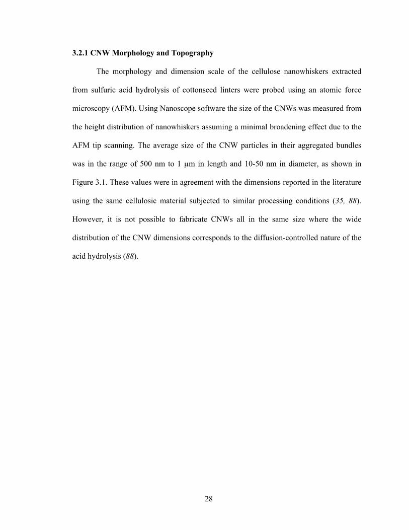
3.2.1 CNW Morphology and Topography
The morphology and dimension scale of the cellulose nanowhiskers extracted
from sulfuric acid hydrolysis of cottonseed linters were probed using an atomic force
microscopy (AFM). Using Nanoscope software the size of the CNWs was measured from
the height distribution of nanowhiskers assuming a minimal broadening effect due to the
AFM tip scanning. The average size of the CNW particles in their aggregated bundles
was in the range of 500 nm to 1 µm in length and 10-50 nm in diameter, as shown in
Figure 3.1. These values were in agreement with the dimensions reported in the literature
using the same cellulosic material subjected to similar processing conditions (35, 88).
However, it is not possible to fabricate CNWs all in the same size where the wide
distribution of the CNW dimensions corresponds to the diffusion-controlled nature of the
acid hydrolysis (88).

29
Figure 3.1 (A) AFM images of the morphology of cellulose nanowhiskers that were obtained by drying their aqueous suspension. (B) Higher resolution AFM images of the cellulose nanowhiskers, depicting in more intimate detail the interactions among them in an aqueous solution.
Researchers have found that the dimension scale of particles, as well as their
specific topography, is of great importance in the design of nanocomposite scaffolds,
where needle-shaped particles showed an increase in the cell differentiation profile
compared with rod and spherical shaped particles (9). Perhaps the needle-like structure of
our synthesized CNWs, along with their nano-sized dimension shown in Figure 3.2,
could increase the potential application of the fabricated hydrogel nanocomposite for
further scaffolding in tissue engineering.
30
Figure 3.2 AFM images of two-dimensional and three-dimensional height maps presenting the morphology and topography of the needle-like cellulose nanowhiskers, which they were hydrolyzed from cottonseed linter microcrystalline cellulose precursor and were suspended in an aqueous solution.
3.2.2 CNW Colloidal Suspension
Cellulose nanocrystals are generally insoluble in common solvents, which leads
them to form a colloidal suspension when placed in an aqueous medium (35). The
stability of these suspensions depends on the dimensions of the dispersed particles, the
particle polydispersity, and the particle surface charge (35). Researchers have found that
the surface charge introduced during the acid treatment of CNWs can directly control the
whisker-whisker interactions, the rheological behavior of their suspensions, and the
stability of their colloids (89). For example in sulfuric acid (H2SO4)-treated cellulose, the
formation of sulfonic groups (SO3-2) on the surface of the CNW particles results in a
negatively charged surface above the acidic pH (89, 90). Thus, the anionic CNW surfaces
in the H2SO4-treated cellulose, in contrast to the hydrochloric acid (HCl)-treated
cellulose, give rise to electrostatic repulsion, which stabilizes the CNW colloidal
suspension and controls subsequent aggregation driven by hydrogen bonding (89, 90). In
fact, the formation of stable colloids without introduction of strong acid groups is a novel

31
phenomenon in the H2SO4-treated cellulose. It introduces a non-thixotropic behavior in
the CNWs and their surface charge properties, leading to an acceptable level of CNW
dispersion in aqueous as well as organic media (89, 90). The SEM images in Figure 3.3
confirm the presence of our stable colloidal suspension of H2SO4-treated cellulose in an
aqueous solution where the samples were collected directly from the dialysis tubes.
Figure 3.3 SEM images of the aggregation of cellulose nanowhiskers in form of stable colloidal suspension in an aqueous solution at different magnifications.
3.2.3 CNW Dispersion
The successful extraction of CNW fillers from different sources of cellulose and
their subsequent uniform dispersion within a host matrix does not always lead to the
formation of a cellulosic nanocomposite with the desired chemical and physical
properties. Poor fiber-dispersion generally increases the probability of gas entrapment
and air bubble formation while adversely introducing a gradient of nanowhisker
concentration within the medium. This ultimately reduces the intended performance of
the system. This in fact has introduced a major problem in the mass production of
cellulose-based nanocomposite, where significant aggregation of CNWs due to strong

32
inter-particle affinity has limited their industrial application. As such the processing
method plays a significant role in the adhesion properties of filler-filler and filler-matrix
interactions during the fabrication of cellulosic nanocomposites (35, 91). This was also
the case in our previous study (70).
The tight agglomeration of CNWs and their strong affinity for one another, the
presence of intermolecular hydrogen bonding within the cellulose chains, and a strong
hydrophilic interaction in between the cellulose chain layers were clearly obvious from
the AFM image in Figures 3.1 and 3.2 as well as from the SEM image in Figure 3.3.
However, freeze-drying the CNWs and pre-dispersing them in an acetone suspension
prior to mixing with the CAP or COL clearly reduced the intermolecular forces between
the individual strands of cellulose and controlled the degree of agglomeration, resulting
in favorable whisker-whisker interaction. This technique notably changed the aggregation
behavior of the CNWs while preserving the nature of the nanowhiskers without using
toxic chemicals. Figure 3.4 and Figure 3.5 display the dispersion of CNWs as seen using
ESEM imaging at low voltage; this confirms that the nanowhiskers are separated by the
disruption of intermolecular hydrogen-bonding interactions while the CNW network
remains intact within the suspension. The average size of the dispersed nanocrystals,
inferred from the TEM images, was approximately the same as that observed in the AFM
images. It is worth noting that our ESEM microscopy was limited by the immediate
degradation of CNWs at a higher magnification, with the high-energy electron sending
off from the SE2 detector hitting the CNW surface. This phenomenon also limited the
subsequent observation of the individual whiskers at the nanoscale.

33
Figure 3.4 Transmission electron micrograph from a freeze-dried/pre-dispersed sample of cellulose nanowhiskers.
Figure 3.5 TEM image of the freeze-dried and pre-dispersed cellulose nanowhiskers in acetone prior to the fabrication of the nanocomposite materials.
34
3.3 Summary and Future Directions
The cellulose nanowhiskers were prepared using an acid hydrolysis, and were
freeze-dried and dispersed prior to being embedded into the biopolymer matrices. The
carbohydrate- and protein-based nanocomposites were then fabricated as discussed in
Chapter 4 and Chapter 5, respectively.
35
CHAPTER 4 1
FABRICATION AND CHARACTERIZATION OF A BIO-INSPIRED
CARBOHYDRATE-BASED NANOCOMPOSITE REINFORCED WITH CNWs
This chapter discusses the impact of processing methods on the final performance
of a carbohydrate-based nanocomposite reinforced with CNWs. Also, the mechanical and
thermal properties of the nanocomposite are investigated with respect to increasing
volume fraction of CNWs. Careful control of the CNW dispersion within the biopolymer
matrix resulted in a significant system enhancement at a small amount of nanofiller
concentration. Finally, theoretical mechanical models were also investigated and
compared with the experimental results, predicting the percolation of CNWs within the
biopolymer matrix.
4.1 Fabrication of the Cellulose Acetate Propionate- Cellulose Nanowhisker
Composite
An aqueous suspension of cellulose nanowhiskers was obtained using the
fabrication method discussed in Chapter 2, Section 2.1.1. The CNW suspension was then
freeze-dried prior to mixing with the cellulose acetate propionate matrix in order to form
the CAP-CNW composite. Different processing techniques were applied using methods
described in Chapter 2, Section 2.1.2 in order to study the effect of fabrication methods
1 The content of this chapter is mainly based on our journal article published in "Polymer" and our book chapter in "Springer-Verlag Berlin Heidelberg".

36
on the final performance of the CAP-CNW composite as the nanowhiskers were
incorporated within the semi-crystalline CAP medium and discussed in details next.
4.2 Characterization of the Cellulose Acetate Propionate- Cellulose Nanowhisker
Composite
The structure, morphology, and distribution of the CNWs within the CAP matrix
and the mechanical/thermal properties of the CAP-CNW composites were studied by a
variety of techniques as described in this section.
4.2.1 Microstructure of the CAP-CNW Composite
In general, it is well known that the fabrication technique and the experimental
conditions have a direct impact on the microstructural behavior of a nanocomposite with
the subsequent effect on its final performance, mechanically and thermally. In a CNW-
based composite, these parameters strongly affect the topological dispersion of
nanowhiskers and hence the final properties of the composite (35). A poor fiber-
dispersion generally increases the probability of gas entrapment and air bubble formation
while adversely introduces a gradient of nanowhisker concentration within the medium,
which ultimately reduces the intended mechanical and thermal performance of the
composite. Therefore, the pre-dispersion of our nanowhiskers in acetone within a
controlled evaporation temperature during the fabrication (as described in Section 2.1.2)
introduced a homogeneous suspension and a uniform surface feature at different CNW%
by weight. The applied method notably reduced the formation of inhomogeneous regions
such as air bubbles, while also inhibited the CNW flocculation during the nanocomposite

37
fabrication. As a matter of a fact, the strong affinity of cellulose not only to itself but also
to other hydroxyl containing material along with the control over mixing the two have
established an efficient inter-molecular bonding between CNW and CAP fibers with no
indication of nanofiller agglomeration as it was evidenced from the SEM images in
Figure 4.1. Similarly, the homogenous dispersion of the CNW filler phase within the
CAP medium was also tested by the thermogravimetric analysis (TGA) of different
regions of the cast films as later described in Section 4.2.3. The smooth TGA profiles of
our fabricated nanocomposites with no indication of a separate degradation stage
suggested the successful grafting of CNWs within the host CAP matrix. We believe that
the quality of the CNW dispersion and their favorable interactions have a significant role
in the formation of a three-dimensional percolating as shown in Figure 4.1 and discussed
in details in Section 4.2.2.
Figure 4.1 SEM images of the dispersion of CNWs within the CAP medium at 3% by weight at two different magnifications.
In principle, cells in a human body exist in a nano-featured environment consist of
complex mixture of pores, ridges, and ECM fibers (24). Nano-sized components have a
larger number of binding sites available to the cell membrane surface receptors (18, 23),

38
and hence promote a higher degree of interactions with cellular membrane proteins,
resulting in the enhancement of cell adhesion. Indeed, the SEM images of the CAP-CNW
composite materials shown in Figure 4.2 indicated the presence of such a nano-scale
morphology.
Figure 4.2 Cross-sectional SEM images of the fibrous architecture of CAP-CNW composites at 0.2% by weight of nanofiller concentration at two different magnifications.
It is also worth mentioning that the processing technique has a leading role in the
progress of porosity within a composite system. In our CAP-CNW composite, the
possible source of porosity and its growth come from both the removal of entrapped
water during the freeze-drying of CNWs and the evaporation of acetone solvent in the
mixture of CNW with CAP matrix prior to the film formation. Nevertheless, the negative
effect of the porosity growth on the mechanical performance of a system represents a
major dilemma in composite science, which needs to be effectively controlled. In general,
an increase in the aspect ratio and volume fraction of the reinforcing agent tends to
increase the porosity content in a fabricated composite. To observe the porosity in our
designed systems and to ensure their uniformity for the subsequent mechanical analysis,
SEM images were obtained from the cast films at different filler concentrations. These

39
images essentially suggested the same diameter range for the distributed pores and a
weak dependence on the whisker weight percent (Figure 4.3). This observation then
justified the comparison of the experimental results at different filler volume fractions as
later discussed in Section 4.2.2.
Figure 4.3 SEM images of the macroporous CAP-CNW composites at: (A) 0.2% by weight and (B) 9% by weight of nanofiller concentrations.
Furthermore, the principal requirements, such as mass-transport for cell nutrition,
open channels for cell migration, and surface features for cell attachment promote the
formation of a porous landscape in the design of a bio-scaffold (92). A controlled porous
structure allows the diffusion of fluids and gases deep into the material, encouraging cell
seeding throughout, in order to form and regenerate new tissue (93). Likewise, a porous
landscape could effectively alter the biological functioning of the material by providing a
balance between the temporary mechanical/chemical stability of the scaffold and the
effective mass transport of the cultured cells. The 3D aggregates of our small-sized pores
in Figure 4.4 represented the potential capability of our uniform porous assembly to
create a viable cell migration site for further tissue regeneration (assuming the average

40
dimension of a porous scaffold that would be relevant for the capture and migration of
epithelial cells is in the range of 2 – 6 µm).
Figure 4.4 SEM images of the CAP-CNW composite, illustrating the porous structure of the biomaterial with 0.2% weight of nanowhiskers at two different magnifications.
According to the theory of contact guidance (94, 95), the maximum probability
for the migration of a cell in a preferred direction depends on the chemical, structural and
mechanical properties of the scaffold (25). For example, electrospun nano-fibrous
scaffolds offer a better cell-adhesion medium in the direction of the aligned fibers
throughout the volume, and also induce a notable increase in the rates of cell proliferation
(24, 25, 30, 96). In cellulose, the magnetic susceptibility of the individual C-C, C-O, C-H,
and O-H bonds in the D-glucose monomers and their relative orientation in the crystal
can effectively induce the alignment of cellulose nanowhiskers in the perpendicular
direction to the applied external magnetic field (56). Also, the ester groups at the surface
of the CNWs resulting from the sulfuric acid hydrolysis can assist in their magnetic
orientation (35). The cross-sectional SEM images of the CAP-CNW nanocomposites,
shown in Figure 4.5 and Figure 4.6, illustrate the impact of the nanocrystal alignment on
the morphology of the nanocomposite that has been exposed to a homogenous magnetic

41
field of 0.3 T. Hence, the ability to orient the cellulose nanocrystals by subjecting them to
a weak external magnetic field could potentially provide an important design tool to
influence and control the morphology of the nanocomposites, and thus improve the
response of the cultured cells in the direction of the aligned CNWs within the bio-
engineered scaffold (30).
Figure 4.5 SEM images of CAP-CNW composites containing 0.2% by weight of nanowhiskers: (A) a non-oriented microstructure and (B) an oriented morphology resulting from exposure to a homogenous magnetic field of 0.3T.
Figure 4.6 SEM images of a cross-section of the magnetically aligned CAP-CNW composite containing 0.2 wt.% cellulose nanowhiskers at two different magnification, A (x1000) and B (x10000) where H represents the direction of the magnetic field.

42
4.2.2 Mechanical Properties of the CAP-CNW Composite
The mechanical performance of micro/nanocomposites under specified working
conditions depends well on major parameters including the morphology and geometry of
the constituents, the concentration/volume fraction of each phase, the mechanical
properties of the composing phases; the distribution of the phases as well as their relative
positioning, and finally the quality of the interface between the fillers and the host matrix.
As a special class of nanocomposites, CNW-based composites and the parameters
affecting their mechanical properties have been investigated, among others, by (35, 97,
98). Based on the morphology and the microstructure of the CAP-CNW composites
investigated in the previous section, first the experimental tensile tests were performed on
a nonlinear range. Then, by using three distinct multiscale homogenization schemes, the
effective mechanical properties of the nanocomposites were theoretically estimated and
compared with the experimental results as described next.
4.2.2.1 Experimental Tensile Tests
The tensile tests of the CAP-CNW composites were performed at 37 oC (body
temperature) on samples with varying filler concentrations and on samples obtained via
different processing techniques at a fixed concentration. These latter samples consisted of
0.2 wt.% CNWs that were combined with the polymer by one of the following three
methods: (1) The direct mixing of the freeze-dried CNWs with the CAP solution, (2) The
pre-dispersion of CNWs in the acetone suspension followed by mixing with the CAP
solution, and (3) The orientation of the pre-dispersed CNWs under an externally-applied
magnetic field of about 0.3 T in an acetone suspension containing CAP. The notable

43
advantages and enhanced properties of nanocomposites, in which nanoparticles in
general, and cellulose-based nanoparticles in particular were magnetically aligned by the
application of an external field, have been well documented (56-58). The alignment of
the CNWs introduced anisotropy in nanocomposites resulting in considerable differences
in the storage modulus between the direction perpendicular to the magnetic field and that
parallel to the magnetic field (59, 60). Thereby, the experimental tensile tests in this study
were performed in the transverse direction to the applied magnetic field as shown in
Figure 4.6.
4.2.2.1.1 Mechanical Performance of the CAP-CNW composite obtained by different
processing methods at a fixed CNW concentration of 0.2 wt.%
The general observation from all the three applied techniques was that the
processing method had a direct impact on the morphological characteristics of the CNWs
and the manner by which they resided within the host matrix, and ultimately, on the
mechanical performance of the nanocomposite system as a whole (35). The stress vs.
strain behavior of the CAP-CNW composites generated from classical tensile tests is
shown in Figure 4.7A and the calculated mechanical properties are summarized in Table
4.1. Clearly, dispersing the CNWs in the CAP solution and subsequently aligning them
using an externally-applied magnetic field resulted the enhancement in the mechanical
properties of the nanocomposite (considerably in the ultimate strain and moderately in the
modulus). This significant improvement was most likely due to the prevention of the

44
whisker agglomeration and as a result, a better filler/matrix interfacial contact and
interaction.
4.2.2.1.2 Mechanical Performance of the CAP-CNW composite obtained by pre-
dispersion at different CNW concentrations
For the best composite performance, there generally exists an optimum filler
concentration that depends on the nature of the host matrix, matrix/filler interactions and
filler/filler inter-connectivity. To obtain this optimum value for our nanocomposite
system, the tensile tests were conducted on samples having 1, 3, 6, and 9 wt.% of
whiskers, and were created by the pre-dispersed processing technique in order to reduce
the negative effect of undesired fiber agglomeration (method 2 described previously). In
order to ensure the validity of the comparisons among the various mechanical property
results based on our previous work (71), the pore distribution in these different films was
ascertained as well (Figure 4.3).
The results summarized in Figure 4.7B and Table 4.1 indicated a considerable
enhancement in both tensile modulus and ultimate tensile strength of the nanocomposites
whose filler concentration was up to about 3 wt.%. However, for samples with
nanowhisker concentrations higher than 3 wt.%, a substantial decrease in the tensile
performance was observed. Based on our previous study (71), we believe that the
formation of a rigid percolating network of the CNWs within the host matrix introduced
an unusual stiffening effect on the cellulose-based nanocomposite at the low filler content
below 3 wt.% and above the percolation threshold. Nevertheless, the likelihood of the

45
presence of filler agglomeration, due to the strong hydrogen bonding interactions among
the nanowhiskers with the increase in their concentrations, could further explain the
degradation of tensile performance as observed in nanocomposites with higher CNW
contents (6 and 9 wt.%).
Figure 4.7 True stress vs. true strain curves of the CAP-CNW composites obtained from classical tensile tests at body temperature (37 oC). (A) For different processing

46
techniques at a fixed 0.2 wt.% CNWs (B) at different whisker volume fractions using the pre-dispersed technique (method 2).
Table 4.1 Results from tensile measurements for samples prepared by different processing methods and for samples having various nanowhisker concentrations.
Filler Content (wt.%)
Tensile Strength (MPa)
Strain at Break (mm/mm)
Elastic Modulus (MPa)
0 2.9 ± 0.6 0.020 ± 0.002 200 ± 22
0.2 (Not-Disp) 3.4 ± 0.8 0.021 ± 0.007 180 ± 31
0.2 (Disp) 3.8 ± 0.3 0.022 ± 0.004 225 ± 18
0.2 (Disp-Aligned) 5.2 ± 0.4 0.031 ± 0.007 375 ± 17
1 8.1 ± 0.7 0.044 ± 0.007 341 ± 18
3 8.7 ± 1.2 0.048 ± 0.006 456 ± 19
3 (Disp-Aligned) 7.9 ± 1.5 0.050 ± 0.008 462 ± 24
6 4.6 ± 0.7 0.021 ± 0.003 410 ± 24
9 4.1 ± 0.5 0.019 ± 0.004 365 ± 33
Based on the considerable effect that the application of a weak magnetic field had
on the properties of the nanocomposites with only 0.2 wt.% CNWs, we believe that the
mechanical performance (both modulus and strength) of our system having a filler
content higher than 0.2 wt.% can also be further enhanced through the alignment of the
nanofibers with a magnetic field higher than 0.3 T. In fact, a stronger magnet (56, 59),
would be necessary for the nanocomposites with CNWs above 0.2 wt.% where the
combined effect of the high fraction of CNWs would prevent such an orientation under a
weak magnetic field. Moreover, the effect of fiber alignment on mechanical properties at
the lower concentration of 0.2 wt.% was closely comparable to that observed for samples
having the optimized concentration of nanowhiskers at 3 wt.%, albeit in the absence of a
magnetic alignment, as is evident from the tensile moduli shown in Figure 4.8 and

47
highlighted in Table 4.1. Given this fact, we conclude that the rearrangements of the
nanoparticles due to the magnetic alignment could potentially introduce a favorable
filler/filler interaction, avoiding the possible adverse effect of their aggregation, while at
the same time readily provide a better interfacial adhesion with the host matrix. This
could also effectively change the amount of optimal concentration of the fillers, which in
our study was predicted to be 3% by weight of CNWs (70).
Figure 4.8 Comparison in the elastic moduli of the CAP-CNW composites for samples containing 0.2 and 3% by weight of nanowhiskers that were either isotropic or aligned under an externally-applied magnetic field.

48
4.2.2.2 Theoretical Mechanical Modeling 2
To ensure the accuracy of our experimental data and to predict the effective
mechanical properties of the CNW-based composites at low filler content, the multiscale
homogenization schemes such as the mean field theory, the percolation method, and the
upper bound solution were investigated in this study assuming a perfect bonding exists
between the fillers and the matrix.
4.2.2.2.1 Mean Field Theory
The theoretical Halpin-Kardos mean field approach has been extensively applied
in order to predict the elastic behavior of composites with short and discontinuous fibers
(35, 99-102). This model is intended to illustrate the strong stiffening effect of the
crystalline phase in a polymeric medium based on the morphological geometry of the
individual crystallites and their distribution in space but not much on the extended inter-
crystallite interactions (100). This system, exhibiting a heterogeneous anisotropic
material with the reinforcing inclusions in random orientations and asymmetrical
geometry, can then be treated as a laminated solid (99, 103). In terms of lamination
theory, such a solid is mathematically equivalent to an arrangement of n plies where the
unidirectional fibers within each ply are parallel to one another and the plies are oriented
in an angle of (𝜋 𝑛) with respect to one another (100). Two such laminates fabricated
from thin plies with the unidirectional short fibers oriented in (00, +90, ±450, 90, 0) can
nearly predict the properties of a material with a random homogeneous distribution
2 The content of this section is mainly based on our journal article published in "Journal of the Mechanical Behavior of Biomedical Materials".

49
throughout its volume (100). The mechanical properties of such a thin ply based on the
volumetric and geometric properties of the phases can be summarized from the
micromechanics equations of Halpin-Tsai (100, 104) as follows:
(i) The estimate of the composite stiffness in the longitudinal direction of fibers or 𝐸!!
𝐸!!𝐸!
=1+ 𝜉𝜂𝑉!1− 𝜂𝑉!
with
𝜂 =
𝐸!𝐸!
− 1
𝐸!𝐸!
+ 𝜉 , 𝜉 = 2(𝑙/𝑑)
where 𝑉! is the fibers volume fraction, 𝐸! and 𝐸! respectively represent, the Young's
modulus of the host matrix and the rigid filler in the longitudinal direction of fibers.
(ii) The estimate of the in-plane shear modulus or 𝐺!"
𝐺!"𝐺!
=1+ 𝜉𝜂𝑉!1− 𝜂𝑉!
where
𝜂 =
𝐺!𝐺!
− 1
𝐺!𝐺!
+ 𝜉 , 𝜉 = 1
with 𝐺! and 𝐺! are the elastic shear moduli of the filler and the matrix, respectively.

50
(iii) The elastic stiffness of the composite in the perpendicular direction of fibers (𝐸!!) is
estimated from section (i) with 𝐸! representing the fiber stiffness in the transverse
direction and 𝜉 = 2 due to the effect of 𝐿 𝑑 = 1 in that direction.
(iv) The Poisson's ratio or ν12 is approximately obtained from the rule of mixtures as
𝜈!" ≅ 𝜈!𝑉! + 𝜈!𝑉!
where 𝜈 and 𝑉 respectively represent the Poisson's ratio and the volume fraction of the
filler (𝑓) and the matrix (𝑚).
By considering the invariant behavior of the stiffness matrix for the laminated
composite, the effective elastic properties then can be described as below:
𝐸 =4𝑈!(𝑈! − 𝑈!)
𝑈!
𝜈 =(𝑈! − 2𝑈!)
𝑈!
𝐺 = 𝑈!
where these invariant parameters 𝑈! are described in terms of the engineering constants
of an orthotropic unidirectional ply material in a laminar system (100) as
𝑈! = 18 (3𝑄!! + 3𝑄!! + 2𝑄!" + 4𝑄!!)
𝑈! = 18 (𝑄!! + 𝑄!! − 2𝑄!" + 4𝑄!!)
with
𝑄!! = 𝐸!!
1− 𝜈!"𝜈!"

51
𝑄!! = 𝐸!!
1− 𝜈!"𝜈!"
𝑄!! = 𝜈!"𝑄!! = 𝜈!"𝑄!!
𝑄!! = 𝐺!"
In classical composite science, a minimal interaction between the reinforcing
filler is desired to obtain a discrete distribution of fillers within a continuous medium.
However, an opposite trend is observed in a composite reinforced by cellulose
nanowhiskers. As the affinity between the filler and the host matrix increases, the
hydrogen-bonding forces holding the CNWs together are interfered, which subsequently
affect the mechanical percolation of nanofibers and their formation of a rigid network
within the medium (98, 105). Therefore, the topological arrangement of nanofibers and
their interactions play a significant role in the mechanical behavior of a CNW-based
composite. Perhaps for this reason, the predicted values (97, 98, 106) from the Halpin-
Kardos model neglecting the filler/filler interactions would better describe the composite
behavior in the glassy state than the rubbery phase where the majority of the composite
stiffness is coming from the crystalline nanowhiskers and their interconnectivity. As a
result, a homogenization scheme such as the percolation theory discussed next could
better explain the unusual stiffening behavior of a CNW-based composite at low filler
content where the spatial arrangement of CNWs and their interactions create a 3D rigid
percolating network.

52
4.2.2.2.2 Percolation Method
As a statistical-geometry theory, the percolation concept was first introduced by
Broadbent and Hammersley in 1957 to formulate a simple stochastic model for a random
distribution throughout a medium (107). As its main purpose, this technique studies the
behavior of an incomplete set of interconnected elements and allows the transition from a
local to an infinite communication state where the critical volume fraction or the
percolation threshold separates the two phases (35). Perhaps, this theory can describe the
behavior of a CNW-based composite where the high tendency of cellulose nanowhiskers
to interconnect with one another by strong hydrogen bonding forms a rigid percolating
platform and imparts an unusual mechanical stability at a low filler concentration.
Motivated by this possibility, Quali et al. (108) extended the classical series-parallel
model proposed by Takayanagi et al. (109) to describe the behavior of the nanocomposite
by setting the percolating filler network in parallel with a series composed of the matrix
and the non-percolating filler phase as illustrated in Figure 4.9.

53
Figure 4.9 Schematic representation of the series-parallel model for a CNW-based composite with ψ indicating the volume fraction of the percolating nanofiller phase; cellulose nanowhiskers.
From this model, the effective elastic tensile modulus of the composite, 𝐸! is then
defined as:
𝐸! = 1− 2𝜓 + 𝜓𝑉! 𝐸!𝐸! + (1− 𝑉!)𝜓𝐸!!
1− 𝑉! 𝐸! + (𝑉! − 𝜓)𝐸!
where 𝑉!, 𝐸! and 𝐸! represent the fiber volume fraction, the moduli of the filler (rigid)
and matrix (soft), respectively. In Quali et al. model, 𝜓 corresponds to the predicted
volume fraction of the percolating rigid phase and participates in the load transfer
throughout the medium (108). This adjustable parameter is given by
𝜓 = 0 ,𝑉! ≤ 𝑉!!
𝜓 = 𝑉!𝑉! − 𝑉!!1− 𝑉!!
!
,𝑉! > 𝑉!!

54
where 𝑏 as the critical percolation exponent describes the network density with a
universal value of 0.4 for a three-dimensional fiber system (110, 111). 𝑉!! refers to the
critical volume fraction or the so-called percolation threshold, which depends on the
aspect ratio of the rigid fillers and their distribution within the medium. For an assembly
of rod-like CNW particles, the percolation threshold (𝑉!!) was derived from a numerical
simulation described in (112) and presented as below to achieve a 3D geometrical
percolation
𝑉!! = 0.7𝐿 𝑑
with L and d respectively represent the length and diameter of a fiber.
In a cellulose-reinforced nanocomposite, the percolation theory was found to
reasonably fit the experimental data where the high CNW surface area with numerous
attached hydroxyl groups formed a percolating rigid network within the medium (97, 98,
113-115). The data agreement was assumed to be even more satisfactory at a temperature
above the composite glass transition where the stiffness of the matrix was almost
negligible and the system stability mainly relied on the infinite aggregate of cellulose
nanowhiskers.
In our study, the basic calculation of the upper bound (Voigt model) and lower
bound (Reuss model) from the following equations was also investigated to better assess
the limits on our theoretical Halpin-Kardos and percolation models.
Composite upper bound modulus:
𝐸! = 𝑉!𝐸! + (1− 𝑉!)𝐸!

55
Composite lower bound modulus
1𝐸!
=𝑉!𝐸!+(1− 𝑉!)𝐸!
where 𝑉!, 𝐸! and 𝐸! represent the fiber volume fraction, the moduli of the fiber and
matrix, respectively. It is also worth noting that the concept of upper and lower bounds in
general only establishes the necessary but not the sufficient conditions in the
development of limits on theoretical models and data predictions (100). Additionally, by
implying the volume fractions of voids/pores within the formulation, the lower-bound
limit automatically gets removed from the comparisons.
In our study, the comparisons between the theoretical and experimental tensile
moduli as a function of CNW contents were plotted in Figure 4.10. In this graph, the
experimental tensile modulus of the neat CAP matrix and the CAP-CNW composites at
different filler concentrations was measured at body temperature (37 0C) where the fiber
volume fractions considered the same as the fiber weight fractions due to the small
density of the CNWs (𝜌 = 1.5). For the numerical analysis, the fiber aspect ratio was
obtained from our TEM measurements. Other parameters such as tensile modulus of the
neat matrix (E!) was derived from the initial slope of the stress-strain curve in Figure
4.7B and homogenized upon measuring the volume fraction of voids existed in the
texture of our nanocomposites. In order to obtain an accurate estimation of the porosity
volume fractions, different regions of each nanocomposite film were selected and
imported into a self-coded image processing software. Then, the voids and matrix were
homogenized by the upper bound properties to introduce an effective tensile modulus
using the techniques available in (116). From this analysis, the volume fraction of voids

56
was placed in the range from 12% to 14%, which were almost in agreement with the pore
distribution illustrated in Figure 4.3.
Likewise, the tensile moduli of the fibers (𝐸!) in the longitudinal and transverse
directions were considered 150 and 15 GPa, respectively (35, 113, 117). It is also worth
mentioning that depending on the source of cellulose fibers, these values could change
(112). Nevertheless, 𝐸! of different fiber sources did not appear to significantly change
our numerical results hence the above values were taken in this study. Also, Poisson’s
ratios of the nanofillers (𝜈!) and the matrix (𝜈!) were both considered 0.3 where the
CNW fibers and CAP matrix represented a glassy behavior at body temperature from our
DSC measurements described in the next section, Section 4.2.3 (70).
Figure 4.10 The experimental vs. the predicted effective modulus from three different homogenization schemes with the fiber aspect ratio of f=60.

57
The results in Figure 4.10 indicated that the predicated values from the Halpin-
Kardos model seemed to better fit the experimental data below our optimum volume
fractions (3 wt.%) while the percolation method was in a better agreement above this
value. The discrepancy phenomenon observed here can be explained from the nature of
our nanocomposites and the basic assumptions considered in both the Halpin-Kardos and
percolation techniques.
As it was reported in other studies (35, 113), the numerical values from the
Halpin-Kardos model better predict the experimental data in the glassy state while tend to
fail as the materials enter the rubbery phase. In this study, our tensile measurements were
done at body 37 0C temperature which is much lower than the material glass transition
(Tg =140 0C) measured from the DSC analysis in our previous study (70) and described
next (Section 4.2.3). Therefore, a better agreement between our experimental data and
our predicted value with the Halpin-Kardos model is in general expected below the
composite glass transition. Also, the major assumption in the mean field theory of
Halpin-Kardos is based on the short fiber distribution with no filler/ filler interactions.
This could explain the overestimation of the predicted value in our study at higher fiber
contents where the role of unfavorable filler/ filler interactions in the mechanical
properties of the composite was significant and neglected in the Halpin-Kardos approach.
From the Quali model depicted in Figure 4.9, the data from the percolation theory
gets closer to the lower bound limit where the percolating rigid phase disappears and the
non-percolating filler phase gets in a series with the matrix phase. Hence, the significance
of the nanowhisker interaction comes into play as the CNWs reach the percolation
threshold and introduce a continuous path throughout the medium. However, the

58
experimental threshold generally falls into a lower limit compared to the numerical one.
This may be due to the basic assumption in the calculation of ψ where a mono-disperse
CNW distribution is considered for simplicity and long nanofibers were not taken into
account (112). Also, the presence of larger particles in the matrix material spread
throughout the medium could increase the real domain available to the percolating fillers
during the film formation leading to a lower percolation threshold (35, 112). Hence, these
phenomenological behaviors could explain the higher elastic modulus observed from our
experimental data at low filler content as opposed to the predicted ones from the
percolation theory. In fact, based on our numerical calculation, the critical volume
fraction occurs at 1.17 wt.% while the experimental results present the formation of a
rigid filler network at less than 1 wt.% (Figure 4.10).
Additionally, the statistical percolation theory assumes a systematic trend in the
predicted modulus as the CNW contents are increased regardless of the variation in the
length of nanowhiskers or their undesired interactions leading to non-uniform aggregates
throughout the volume. This could describe the tensile behavior of our system above 6
wt.% where the unfavorable whisker aggregations lead to a much lower mechanical
performance while the percolation theory still predicted a larger stiffness compared to 3
wt.%. It is also worth noting that the theory of percolation generally models the
percolation geometry where a continuous path of elements in a medium is enough to
create a percolating system. However, the analysis gets more complex when it comes to
the mechanical percolation where not only the continuous linkage of the elements within
the matrix but also the nature of the bond linking the elements is required to ensure the
rigidity of the entire system (112).

59
According to the previous studies, the geometry of the fillers was also modified to
better fit the experimental data (118). Such a modification could extend to the aspect ratio
of nanowhiskers, which strongly affects the percolation threshold in a CNW-based
composite (97, 119, 120). In order to better investigate this effect on our numerical
prediction, different ranges of fiber aspect ratios were also considered in this work as
illustrated in Figure 4.11. Similar to the previous result, the Halpin-Kardos model better
fits the experimental data at lower filler content and at a reasonable fiber aspect ratio (f)
below 100. In fact, a drastic change in the geometry of fiber at f =500 or 2500 put the
predicted tensile modulus from the Halpin-Kardos model well above the experimental
measurements (Figure 4.11A) while the opposite trend was observed in the results from
the percolation theory (Figure 4.11B). In summary, we believe that a better consistency
was observed with the percolation method indicating the formation of a three-
dimensional CNW network within the CAP host matrix.

60
Figure 4.11 The comparison of the theoretical models at different ranges of CNW aspect ratios (A) Halpin-Kardos (B) Percolation.
As an important parameter in the design of a tissue engineered scaffold, the
mechanical performance of a structure has a major role in integrating a three-dimensional

61
architecture hosting the cultured cells for their subsequent functions and growth (9, 121).
An ideal scaffold as a structural component must offer a nurturing stable environment for
cells to optimize the tissue growth while at the same time, withstand the exertion of
mechanical stresses developed during the cellular activities. In our materials design,
cellulose nanowhiskers with their high tendency to self-correlate through strong
interactions upon the surface hydroxyl groups have introduced a load-bearing percolating
network within the host matrix to offer an improved mechanical system. The
considerable enhancement in the tensile behavior of our nanocomposite at 3 wt.% filler
content (Figure 4.7B) is believed to be as a result of this three-dimensional CNW
network illustrated in Figure 4.1. In particular, these results confirmed the dominant role
of filler/filler interactions and nanowhisker percolation on the mechanical behavior of a
CNW-based composite. We believe that our nanohybrid material with the enhanced
mechanical properties at such low filler content could potentially offer a new perspective
in the design of a stable mechanical scaffold in tissue engineering when compared to the
mechanical properties of other natural tissues as illustrated in Figure 4.12.

62
Figure 4.12 Stress-strain behavior of the CAP-CNW composite by 3% weight of nanowhiskers was compared with that of natural connective tissues: tendon, ligament, and cornea (122).
4.2.3 Thermal Properties of the CAP-CNW Composite
Following the same fabrication protocol as previously discussed in section 4.2.2,
the thermal performance of the CAP-CNW nanocomposites was also studied for samples
with varying filler volume fractions and for samples obtained via different processing
techniques at a fixed concentration. The samples studied consisted of 0.2% by weight of
nanowhiskers that were combined with the matrix by direct mixing of the freeze-dried
CNWs with the CAP solution, by pre-dispersion of the CNWs in acetone followed by
mixing with the CAP solution, or by aligning the pre-dispersed CNWs in an externally-
applied magnetic field of about 0.3 T.

63
4.2.3.1 Thermal Behavior of the CAP-CNW composite with different processing methods
at a fixed 0.2 wt.% CNW concentration
The DSC thermograms for these different systems exhibit a melting endotherm
peak (Tm) arising from the first heating cycle, and a glass-rubber transition (Tg) arising
from the first cooling cycle and the second heating cycle. There was no indication of re-
crystallization of the nanocomposites upon cooling. Interestingly, these properties were
nearly independent of the processing methods applied in this study, as summarized in
Table 4.2. Similar results were also reported in other studies performed with CNW-
reinforced nanohybrid systems, regardless of the nature of the polymeric host matrix (35,
123), with the exception of moisture-sensitive systems where the presence of water had a
plasticizing effect on the Tg (124). Even though the sample processing method did not
noticeably impact the Tg and Tm of the CAP-CNW composites, the thermo-gravimetric
analysis (TGA) shown in Figure 4.13A illustrated a steady improvement in the thermal
stability as the nanofibers became dispersed or aligned in an externally-applied magnetic
field of 0.3T. The dispersion of the nanowhiskers and their orientation under an external
magnetic field potentially induced a better interfacial interaction with the host matrix,
leading to an enhanced thermal resistivity in the nanocomposites.
4.2.3.2 Thermal Behavior of the CAP-CNW composite with different processing methods
at a fixed 0.2 wt.% CNW concentrations
The optimal concentration of the nanowhiskers required to fabricate a
thermoplastic semicrystalline nanohybrid with outstanding thermal resistance was
determined by probing the thermal performance of samples (prepared by the pre-

64
dispersion of the CNWs in the common solvent followed by the mixing with the CAP
solution) in which the concentration of the CNWs was varied from 0.2 wt.% to 1, 3, 6
and 9 wt.%. DSC measurements, summarized in Table 4.2, show that there was no
significant change observed in the glass-rubber transition temperature (Tg) and the
melting temperature (Tm) as a function of increasing CNW content. However, a steady
reduction in the enthalpy of fusion (ΔHf) occurred with the increase in the CNW
concentrations, possibly due to the introduction of a barrier to the crystallization of the
polymer matrix and a relative reduction in the crystallinity of the entire system. Similar
results were also reported in other studies involving cellulose-based nanocomposites (35,
123).
TGA experiments were also performed to further study the sensitivity of the
degradation temperature of the CAP-CNW composites as a function of nanowhisker
concentration. To accurately capture this trend and better gauge the role of the CNWs in a
semicrystalline composite system, the thermal properties of the pure CNWs were studied
separately. The degradation of the pure CNWs exhibited a three stage weight loss profile,
corresponding to the initial scission of the hydroxyl groups at about 150-200 oC, the
depolymerization, dehydration, and decomposition of glycosyl units followed by the
formation of a char at around 250-300 oC, and finally, the oxidation and breakdown of the
char to lower molecular weight gaseous products above 325 oC (88, 90). However, the
TGA thermograms of the nanocomposites, shown in Figure 4.13B, exhibited only a
single thermal transition, regardless of the CNW content, fact which indicated that CNWs
were homogeneously embedded into the CAP matrix. The actual degradation temperature
increased with the increase in CNW concentrations of up to about 3 wt.%, but decreased

65
at higher filler concentrations due to a higher probability of nanowhisker aggregation and
bundle formation, which may have prevented a homogenous distribution of the CNWs
within the host matrix, as shown in Figure 4.13B and Table 4.2.
Figure 4.13 TGA thermograms of the CAP-CNW composites for: (A) Samples prepared by different processing protocols at a fixed 0.2% by weight of CNW, and (B) Samples with different nanowhisker concentrations using the pre-dispersed processing method.
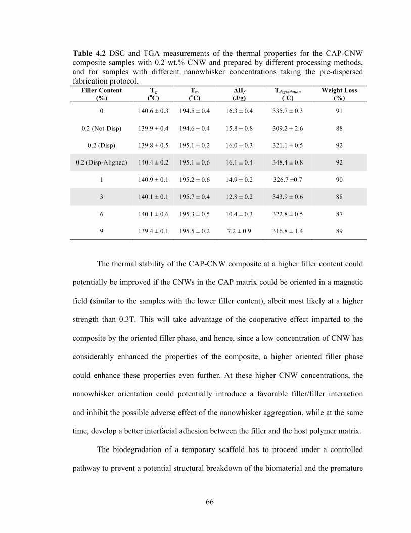
66
Table 4.2 DSC and TGA measurements of the thermal properties for the CAP-CNW composite samples with 0.2 wt.% CNW and prepared by different processing methods, and for samples with different nanowhisker concentrations taking the pre-dispersed fabrication protocol.
Filler Content (%)
Tg (oC)
Tm (oC)
ΔHf (J/g)
Tdegradation (oC)
Weight Loss (%)
0 140.6 ± 0.3 194.5 ± 0.4 16.3 ± 0.4 335.7 ± 0.3 91
0.2 (Not-Disp) 139.9 ± 0.4 194.6 ± 0.4 15.8 ± 0.8 309.2 ± 2.6 88
0.2 (Disp) 139.8 ± 0.5 195.1 ± 0.2 16.0 ± 0.3 321.1 ± 0.5 92
0.2 (Disp-Aligned) 140.4 ± 0.2 195.1 ± 0.6 16.1 ± 0.4 348.4 ± 0.8 92
1 140.9 ± 0.1 195.2 ± 0.6 14.9 ± 0.2 326.7 ±0.7 90
3 140.1 ± 0.1 195.7 ± 0.4 12.8 ± 0.2 343.9 ± 0.6 88
6 140.1 ± 0.6 195.3 ± 0.5 10.4 ± 0.3 322.8 ± 0.5 87
9 139.4 ± 0.1 195.5 ± 0.2 7.2 ± 0.9 316.8 ± 1.4 89
The thermal stability of the CAP-CNW composite at a higher filler content could
potentially be improved if the CNWs in the CAP matrix could be oriented in a magnetic
field (similar to the samples with the lower filler content), albeit most likely at a higher
strength than 0.3T. This will take advantage of the cooperative effect imparted to the
composite by the oriented filler phase, and hence, since a low concentration of CNW has
considerably enhanced the properties of the composite, a higher oriented filler phase
could enhance these properties even further. At these higher CNW concentrations, the
nanowhisker orientation could potentially introduce a favorable filler/filler interaction
and inhibit the possible adverse effect of the nanowhisker aggregation, while at the same
time, develop a better interfacial adhesion between the filler and the host polymer matrix.
The biodegradation of a temporary scaffold has to proceed under a controlled
pathway to prevent a potential structural breakdown of the biomaterial and the premature

67
failure of the system prior to the complete secretion of a native ECM by the cultured cells
(29). Therefore, the enhanced mechanical functionality and thermal stability of the
nanocomposites in the current study could add an advantage into the development of a
stable platform material as a potential scaffold in the context of tissue engineering.
4.3 Summary and Future Directions
In this study, we have developed a bio-inspired carbohydrate-based
nanocomposite comprised of cellulose nanowhiskers embedded and aligned in a cellulose
acetate propionate matrix. When compared to non-biocompatible inclusions such as
carbon nanotubes and Kevlar fillers, CNWs imparted significant strength and directional
rigidity to the CAP-CNW composite even at 0.2% by weight of nanowhiskers. Similarly,
a significant improvement in critical properties was observed when the CNWs were
aligned in an externally-applied relatively weak magnetic field (0.3 T). Magnetically
induced alignment not only improved the directionality and percolation limits of the
nanoparticles within the medium, but also drastically lowered the optimum amount of
CNWs required to obtain the best composite performance mechanically and thermally.
Therefore, highly desirable properties can be induced in cellulose-based composites by
modifying the processing methods, with potential use in scaffolding for tissue
engineering application.
Future direction of the current study could reflect on an investigation of the
mechanical properties of the CAP-CNW composites in the longitudinal direction of the
magnetic field in order to verify the alignment of the CNWs in the transverse direction to
the magnetic field as claimed in literature and was discussed in Section 4.2.2.1.

68
Furthermore, our CAP-CNW designed system was too stiff yet brittle, and hence, would
most likely not be suitable for its intended application as compared to other natural
tissues (Figure 4.12). Therefore, to impart an enhanced ductility with the desired
flexibility to the bio-scaffold material another biopolymer matrix is required, and the
most natural choice has been collagen. As discussed in details in the next two chapters,
the larger elasticity as well the viscous nature of the designed hydrogel bio-inspired
nanocomposite could provide a much better scaffolding candidate for tissue engineering
applications.

69
CHAPTER 5 3
FABRICATION AND CHARACTERIZATION OF A BIO-INPIRED
PROTEIN-BASED NANOCOMPOSITE REINFORCED WITH CNWs
The focus of this chapter is to study the effect of the CNW increasing volume
fraction on the mechanical and thermal properties of a hydrogel nanocomposite as CNWs
are incorporated within a protein-based matrix. Rheological analyses, including
oscillatory strain, time, and frequency sweep, were carried out to study the flow and
deformation of the hydrogel nanocomposite subjected to oscillatory shear and to
investigate the connection of the rheology results to the microstructure. Careful control of
the processing conditions resulted in a viscoelastic hydrogel with a significant
improvement in the system’s mechanical and thermal performance at a small amount of
nanofiller content. A change in the paradigm of the hydrogel nanocomposite behavior
mechanically and thermally, confirmed the formation of a three-dimensional rigid
percolating network giving rise to an enhanced system performance at such low
nanofiller concentration.
5.1 Fabrication of the Collagen- Cellulose Nanowhisker Composite
An aqueous suspension of cellulose nanowhiskers was obtained using the
fabrication method described in Chapter 2, Section 2.1.1. The CNW suspension was then
freeze-dried prior to mixing with the collagen hydrogel in order to form the COL-CNW
3 The content of this chapter is mainly based on a journal article accepted in the "IEEE Journal of Medical Imaging and Health Informatics" and another one to be submitted.

70
composite. Using the pre-dispersion technique explained in Chapter 2, Section 2.1.3, the
microstructural, rheological and thermal behavior of the hydrogel nanocomposite were
investigated as the nanowhiskers incorporated within the collagenous medium and
discussed in details next.
5.2 Characterization of the Collagen- Cellulose Nanowhisker Composite
The structure, morphology, and distribution of the CNWs within the COL matrix
and the rheological/thermal properties of COL-CNW composites were invesigated by a
variety of techniques as described in this section.
5.2.1 Microstructure of the COL-CNW Composite
It is worth mentioning that the processing technique not only affects the inter-
whisker interactions but also the entire nanocomposite microstructure. SEM micrographs
in Figure 5.1 showed the introduction of microporosity in the COL-CNW composite as it
was subjected to different fabrication methods. The leading role in the progress of
porosity in the nanocomposite material came from the removal of entrapped water during
the freeze-drying of CNWs prior to mixing with the collagenous medium as well as the
aftermath freeze-drying of the entire fabricated hydrogel as described in Chapter 2,
Section 2.1.3.
To design an ECM-like structure for tissue engineering, researchers have shown
that the influence of the controlled porous media via the theory of contact guidance to
control the cellular activities while they are secreting their own ECM (9, 10, 121).
Leading requirements such as mass-transport for cell nutrition, porous channels for cell

71
migration, and surface features for cell attachment promote the necessity of a porous
structure for substrate design (125). A feasible bio-scaffold candidate should possess
porosity with the adequate pore size to favor cell adhesion, growth, and proliferation as
well as to facilitate the diffusion of nutrients to and waste products from the implanted
material (9, 126). For example, an external pore size as large as 30 µm in a microporous
vascular prosthesis facilitated the rapid tissue ingrowth and lining of endothelial-like cells
(92). The resulting formation of the desired pore structure is consequently relies on how
well the fabrication method such as the freeze-drying technique is applied (127). Thus,
our fabricated hydrogel nanocomposite possessing a microporous structure could
promote the viability of the substrate for further cell culturing.
Figure 5.1 SEM micrographs presenting the effect of processing methods in the microstructure of the fabricated cellulose-collagen hydrogel nanocomposite at 3 wt.% nanofiller: (A) at room temperature with no microporous landscape (B) Porous induced microstructure upon the hydrogel freeze-drying.
At common ambient environmental conditions, cellulose will have at least a
monomolecular layer and up to several associated molecular layers of water. The strong
affinity of cellulose not only to itself but also to other hydroxyl containing materials
established an efficient inter-molecular bonding between collagen fibers with no CNW

72
agglomeration as it was observed from the SEM images in Figure 5.2. This is in fact due
to the applied pre-dispersion processing method (Chapter 2, Section 2.1.3), which had
notably reduced the formation of the inhomogeneous regions such as air bubbles as well
as inhibited the CNW flocculation during the nanocomposite fabrication. This was also
verified by the thermogravimetric analysis (TGA) of the different regions of the hydrogel
as described in Section 5.2.3. The smooth TGA profiles of the fabricated nanocomposite
with no indication of a separate degradation stage suggested the successful grafting and
well separation of the CNWs within the collagenous host matrix. We believe that the
quality of the CNW dispersion and their favorable interactions have a significant role in
the formation of a three-dimensional percolating network as well as in the
rheological/thermal behavior of the hydrogel nanocomposite as described next in
Sections 5.2.2 and 5.2.3.
Figure 5.2 SEM micrographs showing the fibrous nature of the fabricated collagen-cellulose hydrogel nanocomposite at 3% by weight of CNWs forming a three-dimensional percolating network at different magnifications.
Researches have shown that cells react to topography primarily because they
encounter topographic structures continuously in their life within the body (17). Previous

73
studies have confirmed the reaction of different cell types to micro- and nano-topography
even to features with as small as 10 nm height (128). As a matter of fact, the topography
of a substrate material has an important signaling modality in controlling cell functions
such as changes in shape, differentiation and adhesion through the biophysical cell
mechanism (129, 130). As an example, human corneal epithelial cells (ECs) appeared to
elongate and align along the patterns of grooves and ridges in a rough substrate with the
feature dimensions as small as 70 nm, whereas ECs were mostly round on a smooth
substrate (131). As it was also reported, the differentiation of human mesenchymal stem
cells was much stimulated on a nanoscale topographic disorder than on a highly-ordered
substrate mostly due to the generation of anisotropic stresses (9, 132). From culmination
of such design, it seems that the fibrous porous morphology along with the micro and
nano-topographic disorder observed in our COL-CNW composite (Figure 5.1 and Figure
5.2) could potentially introduce a feasible substrate for scaffolding in tissue engineering.
5.2.2 Mechanical Properties of the COL-CNW Composite
As a well-known technique, shear test has been applied in previous studies to
measure the viscoelastic properties of hydrated collagen gel as well as to correlate the
results with the corresponding microstructural arrangement (133-135). In this work, to
find the optimum amount of nanofiller phase for the best composite performance, a
similar trend of CNW weight percent of 1, 3, 6, and 9 was considered like the previous
study in Chapter 4, and by taking the pre-dispersion processing technique. Furthermore,
different oscillatory shear tests along with a step-by-step rheology analysis were carried
out to investigate the flow and deformation of the COL-CNW composites subjected to
74
increasing CNW% by weight under specific conditions. First, an amplitude sweep over a
strain range was probed at different frequencies in order to obtain the linear viscoelastic
region (LVR) in both neat collagen and COL-CNW composites. Then, a time-dependent
study was performed on hydrogel materials through running an oscillatory time sweep
while deforming the materials in their LVR. Finally, the dynamic mechanical spectra of
the fabricated hydrogels were studied by using a frequency sweep under an oscillatory
shear subjected to the maximum strain amplitude of the pre-determined LVR.
5.2.2.1 Oscillatory Strain Sweep
When a material is subjected to a small or sufficiently slow deformation, the
molecular arrangements over the volume of the material are never far from equilibrium
(136, 137). The mechanical response of the material then is just a reflection of the
dynamic processes which occur at the molecular level and constantly continue even in an
equilibrium system (136, 137). This region is typically called the domain of linear
viscoelasticity where the linear stress-strain dependence describes the material behavior
as a single function of time. As a result, finding the range of LVR in a material and
measuring the corresponding properties typically provide a bridge in filling the gap
between the molecular structure and the performance of the material at the macroscopic
level.
In order to determine the LVR in our hydrogel materials, an amplitude strain
sweep was carried out on samples subjected to an oscillatory shear strain of maximum
amplitude γ and angular frequency ω. The results of the oscillatory shear stress as a
function of time can be separated into in-phase and out-of-phase components where they
75
are respectively related to the elastic or storage modulus (G') and the viscous or loss
modulus (G'') as the material undergoes deformation (138, 139). The dependence of G'
and G'' on γ for the hydrogel materials, the pure collagen and the COL-CNW composites,
was tested at different angular frequency range of 0.1, 1, and 10 rad/sec.
As an example, a comparison between the pure collagen and the COL-CNW
composite at 3% by weight of nanowhiskers were completed and illustrated in Figure 5.3.
The higher the frequency of deformation, the smaller the LVR was spotted in both
hydrogel systems where the materials had shorter time to store energy (similar trend was
also observed for the G'' data but not shown for a better graphic representation).
However, the much shorter LVR at the higher frequency was immediately captured in the
COL-CNW composite as opposed to that of in the neat collagen. This is due to the CNW
entanglement within the collagenous medium resulting in a much shorter time for the
nanocomposite to store energy at the higher frequency. It is also worth mentioning that
the LVR observed in our fabricated neat collagen was in agreement with the strain-sweep
data reported in previous studies (139-141). However, the higher G' observed in our
collagen hydrogel compared to their observations was due to the higher concentration of
collagen fibers in diluted acetic acid considered in our study as opposed to the lower
concentration taken in theirs.

76
Figure 5.3 Frequency dependence of elastic shear modulus in an oscillatory strain sweep to obtain the linear viscoelastic region (LVR) of: (A) Pure collagen (B) COL-CNW composite at 3wt.% nanowhisker.

77
Since the longer the LVR the higher structural stability a material would exhibit,
the frequency ω and the critical strain γ were respectively considered 0.1 (rad/s) and less
than 10% in this study. These values were selected to ensure the linearity of the analysis
in the LVR and to extend the material's stability while keeping the structure intact with
no rupture as it was agitated upon shearing. Similarly, the nonlinearity of the hydrogels
above 10% strain was believed to occur due to the breaking and reforming of the physical
bonding (non-covalent) within the gel materials at higher strains with an apparent
decrease in the elastic modulus. The results from the strain-sweep test for the pure
hydrogel and the COL-CNW composite at 3 wt.% as an example were represented in
Figure 5.4 with the corresponding measurements summarized in Table 5.1. Below the
critical strain, the G' > G'' indicated the presence of a highly structured arrangement with
solid-like behavior whereas increasing the strain above its critical value disrupted the
material network structure and reduced the shear moduli with a progressive indication of
more fluid-like phenomenon. The G' and G'' for both materials displayed very little strain
dependence below 10% shear strain with a subsequent small strain-induced stiffening
prior to final rupture of the hydrogels.
Furthermore, the significant enhancement in the ultimate shear strength and the
storage elastic modulus in the COL-CNW composites indicated that the small addition of
the well-dispersed CNWs (3 wt.%) introduced a substantial elasticity of about twofold
increase into the collagenous medium (Figure 5.4 and Table 5.1). The enhancement in the
mechanical performance of the COL-CNW composite at such low filler concentration
was believed to be as a result of the CNW physical entanglement with the collagenous
medium in which creating a three-dimensional rigid percolating network and introducing

78
a stable structure with high resistance to large strain deformations. Similar improvement
trends were also reported in literature where the small addition of CNWs significantly
enhanced the mechanical performance of the cellulosic nanocomposites with the
percolating CNW nanofiller phase (35, 70, 71).
Figure 5.4 Linear versus nonlinear behavior of the neat collagen and collagen-CNW hydrogel composite at 3wt.% nanofiller in an oscillatory strain sweep where the elastic (G') modulus and applied shear stress (τ) were plotted versus shear strain at angular frequency of ω =0.1 rad/s at room temperature.
Likewise, the optimum amount of the CNW nanofiller in the COL-CNW
composite was observed from the stress-strain curves shown in Figure 5.5 and the
associated measurements summarized in Table 5.1. From these results, a considerable
improvement in the composite shear modulus and ultimate shear strength was reflected
up to about 3 wt.% of the nanowhiskers along with a steady decrease in the samples with
higher CNW content. We believe that the possibility of an unfavorable inter-whisker

79
agglomeration from the strong hydrogen-bonding interactions could explain the negative
effect of the reinforcing agent on the rheological performance of the nanocomposites
beyond a certain amount of filler volume fraction representing the optimum amount of
nanowhisker phase.
Figure 5.5 Stress versus strain curve of the neat collagen and COL-CNW hydrogel composite at different weight of 1, 3, 6, and 9% CNW obtained from an oscillatory strain-sweep subjected to constant angular frequency of ω =0.1 rad/s at an ambient temperature of 25 oC.

80
Table 5.1 Oscillatory stain sweep data of the pure collagen compared to the collagen-cellulose hydrogel nanocomposite at 1, 3, 6, and 9 wt.% CNW under constant ω =0.1 rad/s while deforming the hydrogels within the linear viscoelastic region at room temperature. Filler Content
wt. (%)
Critical Strain
γ (%)
Elastic Modulus
G' (Pa)
Loss Modulus
G'' (Pa)
Critical Shear Stress
τ (Pa)
0 9.99 ± 0.01 827.51 ± 176.02 113.62 ± 40.5 93.49 ± 14.81
1 10.00 ± 0.01 1003.00 ± 46.87 101.63 ± 17.10 124.89 ± 5.26
3 10.01 ± 0.03 1557.50 ± 335.9 269.39 ± 109.6 218.84 ± 12.49
6 10.01 ± 0.02 1436.00 ± 270.15 194.13 ± 70.72 156.51 ± 11.33
9 9.99 ± 0.01 1104.67 ± 65.39 180.01 ± 21.14 140.84 ± 8.84
5.2.2.2 Oscillatory Time Sweep
In general, an oscillatory time sweep is carried out to directly provide the
necessary information regarding the flow behavior of a polymeric material as it
undergoes a macro- or micro-structural rearrangement with time (142). To observe the
true time-dependent behavior of our fabricated hydrogels and to ensure the stability of the
systems during the data collection, the oscillatory time sweeps were probed at a constant
amplitude of strain γ <10% with a constant angular frequency of ω =0.1 rad/s at room
temperature. As a matter of fact, to maintain the elastic structure of the hydrogel
materials and to prevent any nonlinear disruption within the biopolymer network by
overstraining, care was taken to keep the strain low while the materials were going under
deformation in their LVR as described earlier (Section 5.2.2.1).
Considering the optimum amount of the CNW content from the previous strain
sweep test, the time sweep analysis were also reflected on comparing the pure collagen

81
with the Col-CNW composite at 3 wt.% nanowhiskers. As time advanced, the viscosity
of both hydrogel materials presented a rapid increase initially followed by a steady
increase progress (Figure 5.6). This characteristic implied a non-Newtonian behavior
where the flow properties of our fabricated hydrogels were not described by a single
constant and changed as a function of time. Also, the rapid increase followed by the
steady state plateau in viscosity is mostly related to the stabilization of internal network
of the material that can be broken down by shearing and require some time to re-build
itself (143). The steady state increase in the value of viscosity at a constant shear rate
observed in Figure 5.6 confirmed the structural stability of both collagen and collagen-
CNW composite upon shearing over time exhibiting a rheopectic behavior in a complex
fluid. Similarly, as it was reported in literature (89), the H2SO4-treated CNWs showed no
time dependence in viscosity as compared to thixotropic HCl-treated CNWs.
Accordingly, the source of the time dependent rheopecy in our hydrogel nanocomposite
with H2SO4-treated CNWs was the collagen itself not the CNWs since similar trends
were observed in the viscosity profile of both hydrogels. Finally, the higher value of
viscosity spotted in the COL-CNW composite due to the addition of nanowhiskers at
3wt.% verified the successful physical entanglement and the homogeneous particle
distribution of the cellulose nanowhiskers within the collagenous medium representing a
stable structural rearrangement over shearing with time (Figure 5.6).
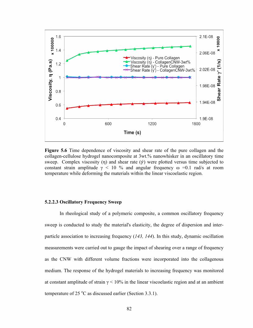
82
Figure 5.6 Time dependence of viscosity and shear rate of the pure collagen and the collagen-cellulose hydrogel nanocomposite at 3wt.% nanowhisker in an oscillatory time sweep. Complex viscosity (η) and shear rate (𝛾) were plotted versus time subjected to constant strain amplitude γ < 10 % and angular frequency ω =0.1 rad/s at room temperature while deforming the materials within the linear viscoelastic region.
5.2.2.3 Oscillatory Frequency Sweep
In rheological study of a polymeric composite, a common oscillatory frequency
sweep is conducted to study the material's elasticity, the degree of dispersion and inter-
particle association to increasing frequency (143, 144). In this study, dynamic oscillation
measurements were carried out to gauge the impact of shearing over a range of frequency
as the CNW with different volume fractions were incorporated into the collagenous
medium. The response of the hydrogel materials to increasing frequency was monitored
at constant amplitude of strain γ < 10% in the linear viscoelastic region and at an ambient
temperature of 25 oC as discussed earlier (Section 3.3.1).
83
As an example, the response of the pure collagen to the changing frequency
amplitude was compared to that of the COL-CNW at 3 wt.% as illustrated in Figure 5.7.
The elastic modulus (G') was spotted to be greater than the viscous modulus (G'') in both
pure collagen and COL-CNW composite over the applied frequencies, implying a more
elastic solid-like than viscous fluid-like behavior in both systems (145). This was also in
agreement with other rheological studies reported in literature for collagenous media
(139-141). Additionally in the process of similar timescale illustrated in Figure 5.7, the
dominancy of G' over G'' with the uniform drop in viscosity η below the critical strain
was nearly independent of frequency in both hydrogels, exhibiting a well-structured gel
where sedimentation was unlikely to occur (143, 144). Likewise, the value of G' and G''
in both hydrogel systems constantly decreased at the higher frequency (above 100 Hz)
where the fibrils entangled like a pseudo-cross-link as a result of the lack of enough time
to loosen up which gave rise to the decrease in the shear moduli (146). Finally, the higher
value spotted for the shear moduli (G' and G'') and the complex viscosity (η) in the COL-
CNW composite upon the addition of 3 wt.% nanowhiskers suggested the effective
entanglement and homogenous dispersion of the CNWs within the collagenous medium
forming a stable structural network. This was believed to be the result of formation of a
three-dimensional percolating network of CNWs fact which imparted an enhancement of
about twofold increase in the amount of mechanical energy stored upon extending the
deformation at higher frequencies as opposed to that of the neat collagen (Figure 5.7).

84
Figure 5.7 Frequency dependence of shear moduli and viscosity of the pure collagen and the COL-CNW composite at 3wt.% nanowhisker in an oscillatory frequency sweep. Elastic modulus (G'), viscous modulus (G'') and complex viscosity (η) were plotted versus angular frequency (ω) under constant strain amplitude of γ < 10 % within the hydrogel linear viscoelastic region.
Likewise, the change in both shear moduli, G' and G", subjected to the increasing
frequency at different amount of CNWs in the COL-CNW composites was observed in
Figure 5.8. A similar trend to the strain sweep data was also spotted in the frequency
sweep experiment where the inclusion of CNW up to an optimum amount reflected the
best composite performance with a steady decline afterwards. Perhaps, the unfavorable
whisker- whisker interaction has introduced an adverse impact on the composite
performance beyond the certain CNW weight percentage.

85
Figure 5.8 The comparison of Frequency dependence of shear moduli of the pure collagen and the COL-CNW composite at 1, 3, 6, and 9 wt.% nanowhisker in an oscillatory frequency sweep. Elastic modulus (G') and viscous modulus (G'') were plotted versus angular frequency (ω) under constant strain amplitude of γ < 10 % within the hydrogel linear viscoelastic region.
In general, understanding the effect of traction forces exerted by cells on an ECM-
like structure is a critical parameter to design a mechanically stable scaffold (139, 140,
147). When cells well spread out on the surface of a scaffold, the contractile forces
spontaneously induced by these cells will transfer to the material and reconstruct it
accordingly (141). Substrates with the larger elasticity can effectively take greater
contractile force to avoid deformation and subsequently provide a better mechanical
support for cell growth (141). This was also evidenced in the previous studies when the
stiffer collagenous gels increased the rate of the cell survival by spreading their
lamellipodium while reducing their apoptosis (141, 148, 149). Therefore, the greater
storage shear modulus (G') observed in our fabricated COL-CNW composite at 3 wt.%

86
compared to that of the neat collagen similarly represented the material capability of
resilience storage and deformation resistance as the CNWs were percolated within the
collagenous medium. The large nanocomposite elasticity as well as the well gel stability
could potentially provide a stable mechanical support for cells to exert the greater
contractile forces on the material as they render their normal activities. This is perhaps
due to the fact that the conjugation of nanomaterials like CNWs to a substrate not only
can affect the subsequent cellular activities but also can compensate the scaffold
limitations such as weak mechanical properties (9). Finally, a comparable viscoelastic
behavior between our COL-CNW composite at 3 wt.% and the orbital connective tissue
derived from bovine (150) was highlighted in Figure 5.9, which could also verify the
feasibility of our fabricated bio-platform for scaffolding in tissue engineering.
Figure 5.9 The comparison of shear moduli in the COL-CNW composite at 3wt.% nanowhisker with that of the bovine orbital connective tissue (150) subjected to an oscillatory frequency sweep. The elastic (G') and viscous (G'') moduli were plotted versus angular frequency (ω) under constant strain amplitude of γ < 10 % inside the nanocomposite linear viscoelastic region.

87
5.2.3 Thermal Properties of the COL-CNW Composite
Calorimetric techniques such as DSC and TGA were probed in this study to
investigate the thermal stability of biological macromolecules; collagen and cellulose; as
well as to detect every state of the changes within their systems as a function of
temperature. The thermal transition in both pure collagen and the COL-CNW composites
at different CNW wt.% from DSC results summarized in Table 5.2 indicated two separate
endotherm peaks during the first heating cycle even with running the experiments at
various heating rates. Likewise, the second endotherm peak (Tm2) in both hydrogel
systems inclined to get sharper at higher enthalpy of fusion (ΔHf) as opposed to that of
the first endotherm peak (Tm1). These transitions could be the result of partial unfolding
and complete denaturation of the collagen macromolecule upon the release of moisture
content and disruption of the intermolecular bonding as the temperature raised. In
previous studies (151, 152), researchers have found that collagen tended to contract and
shorten with minimal structural changes at low temperature below 60 oC while it
completely denatured with a sharp increase in shrinkage at higher temperature. This was
also the case in our experiments (Table 5.2). Similar trends were additionally observed in
the thermal analysis of the ancient parchment where collagen as its major component of
the skin connective tissue matrix was denatured beyond 100 oC (153). Moreover from
previous studies, it seemed that collagen hydrogel derived from rat-tail tendon tended to
unfold and refold below body temperature (154) but became thermally irreversible upon
unwinding of the intermolecular crosslinks at higher temperature where the structure of
collagen was completely disrupted (155). This was evident in our DSC thermograms
where both hydrogel systems were completely denatured in the first heating cycle with no

88
transition peaks observed in the first cooling or the second heating cycles which also
confirmed the irreversibility of our fabricated hydrogels at high temperature.
It is worth mentioning that the addition of CNW wt.% seemed to have no effect
on the melting endotherm of our fabricated hydrogel reinforced materials. Similar results
were also reported in other studies with the CNW-reinforced composites regardless of the
nature of the polymeric host matrix when no chemical modification were applied on the
CNW surface (35, 123) only with the exception of moisture-sensitive systems where the
presence of water had a plasticizing effect on the melting temperature (124). Likewise, it
was evident that the freeze-drying of the fabricated CNWs prevented the effect of
plasticizing due to the extra moist left on the surface of nanowhiskers and subsequently
generating the similar melting endotherm in both pure collagen and the COL-CNW
composites.
Although the addition of CNWs did not noticeably affect the endotherm peaks
observed in the DSC thermograms, our thermo-gravimetric profile (TGA) in Figure 5.10
revealed a different trend when CNWs were incorporated into the collagen matrix. The
TGA experiments were performed to trace the weight loss and decomposition phenomena
in both pure collagen and the COL-CNW composites as a function of temperature under a
controlled atmosphere. To accurately capture this trend and to better gauge the role of
CNWs in our hydrogel system, thermal properties of the pure CNWs were studied
separately. The degradation of the pure CNWs exhibited a three stage weight loss profile,
initiated with the scission of the hydroxyl groups at about 150-200 oC; followed by the
depolymerization, dehydration, and decomposition of glycosyl units and the formation of
a char at around 250-300 oC; and finally, the oxidation and breakdown of the char to

89
lower molecular weight gaseous products above 325 oC which were similarly observed in
previous studies (88, 90). However, no separate degradation stage was observed in the
TGA thermograms of the hydrogel nanocomposites (Figure 5.10), fact which indicated
that the CNWs were completely covered by the collagen fibers as they were
homogeneously dispersed within the host matrix.
Likewise, the actual degradation temperature increased with the increase in CNW
concentrations of up to about 3 wt.%, but decreased at higher filler concentrations due to
a higher probability of nanowhisker aggregation and bundle formation, which may have
prevented a homogenous distribution of the CNWs within the host matrix, as shown in
Figure 5.10 and summarized in Table 5.2. Indeed, the degree of the well dispersion of
CNWs within a polymeric matrix is of great importance in the design of a cellulosic
composite and its subsequence performance, which was directly obvious in our
nanohybrid material where a 40% improvement in thermal decomposition was observed
(Figure 5.10 and Table 5.2).

90
Figure 5.10 TGA thermograms representing the thermal decomposition and the formation of gaseous reaction products of the freeze-dried cellulose nanowhiskers, the pure collagen, and the COL-CNW hydrogel composite.
Table 5.2 DSC and TGA measurements of the thermal properties for the pure collagen and the COL-CNW composites with 1, 3, 6, 9% by weight of nanowhiskers, which were prepared by the pre-dispersed and the freeze-dried fabrication protocol.
Filler Content
wt. (%)
Tm1
(oC)
ΔHf1
(J/g)
Tm2
(oC)
ΔHf2
(J/g)
Tdecomposition
(oC)
Weight Loss
(%)
0 87.2 ± 0.8 449.6 ±11.9 113.1 ± 0.6 739.7 ± 22.4 124.3 ± 1.2 96
1 87.7 ± 1.6 463.1 ± 9.8 113.2 ± 0.3 771.9 ± 16.5 126.3 ± 2.0 95
3 89.6 ± 1.3 487.8 ±15.9 112.6 ± 0.9 789.2 ± 21.1 173.7 ± 0.8 96
6 87.5 ± 0.8 482.6 ± 11.2 112.9 ± 1.5 773.1 ± 18.2 163.6 ± 2.1 95
9 87.6 ± 1.1 465.9 ±12.6 112.7 ± 0.9 786.3 ± 16.9 144.7 ± 2.2 96
To date, various techniques are available to study the heat-induced changes in
collagen and neo-collagenesis in the secretion of new collagenous network in order to

91
achieve therapeutic tissue repairs for a number of medical procedures (151, 155-157). For
example, the effect of heat, which directly influences the biodegradation of a temporary
scaffold material, has to proceed under a controlled pathway to prevent a potential
structural breakdown of the biomaterial and the premature failure of the system prior to
the complete secretion of a native ECM by the cultured cells. Thus, it is evident from our
TGA profiles shown in Figure 5.10 that the well dispersion of CNWs potentially induced
a better interfacial interaction with the collagenous host matrix, leading to an enhanced
thermal resistivity to the complete decomposition of the hydrogel nanocomposite.
5.3 Summary and Future Directions
This work describes the design of a new class of green functional biomaterial
composed of type I collagen (COL) reinforced with cellulose nanowhiskers (CNWs) to
effectively enhance the rigidity of collagen and to better mimic the morphology and
profile features that are characteristic to biological tissues. Microscopy techniques such
as AFM and FE-SEM were conducted to probe the morphology of the CNWs and the
microstructure of COL-CNW composite as the CNWs were incorporated within the
collagenous medium. Rheological analyses including oscillatory strain, time, and
frequency sweep were carried out to study the flow and deformation of the
nanocomposite upon oscillatory shear and their connection to the microstructure.
Calorimetric techniques such as DSC and TGA were performed to measure the thermal
stability and decomposition of the hydrogel material subjected to increasing temperature.
The successful grafting of CNWs within the collagenous medium resulted in a nearly

92
twofold improvement in viscoelastic properties and thermal stability of COL-CNW
composite with only a small amount of filler content, i.e. 3 wt.%. The tendency of CNWs
to interconnect with one another through strong hydrogen bonding gave rise to the
formation of a three-dimensional rigid percolating network, fact which imparted an
excellent nanocomposite performance, even at such low filler concentration. This green
functional biomaterial with its unique features could potentially provide a platform for
biomedical applications such as scaffolding in tissue engineering as discussed next in
Chapter 6.
Future direction of the current study could extend to the alignment of the CNWs
as exposed to a magnetic field while percolating within the collagenous medium. This
could directly affect the mechanical/ thermal properties of the CNW-reinforced hydrogel,
as it was also evidenced in our previous study of the CAP-CNW composite in Chapter 4.
Ultimately, the alignment of the substrate material could add an additional valuable
feature to design a viable scaffolding material based on collagen and cellulose while
closely mimicking the oriented morphology existed in human tissues.

93
CHAPTER 6
BIOCOMPATIBILITY STUDY OF A PROTEIN-BASED
NANOCOMPOSITE REINFORCED WITH CNWs
This chapter investigates the biocompatibility of the collagen-cellulose hydrogel
nanocomposite by using an in-vitro study of human-bone-marrow-derived mesenchymal
stem cells (MSCs) at 8 days of culture. The resulting growth and radial invasion of MSCs
around the hydrogel material is spotted through imaging techniques as described below.
6.1 Cell Culture Method
Biocompatibility is an essential design factor to establish a suitable interface
between cells and scaffold material in order to maintain the activity of functional cells, to
regulate cell behavior, and to further reconstruct three-dimensional tissues (10). In this
study, the biocompatibility of the COL-CNW composite was investigated by observing
cell adhesion and growth on the substrate material based on the model of radial invasion
of a matrix by aggregated cells, described in (86, 87, 158). The radial invasion of the
cultured MSCs around the pre-sterilized COL-CNW composite was spotted in Figure 6.1
where a three-dimensional sandwich assay was formed using a woven mesh nylon ring as
the structural support. Similar results were also observed in the pure collagen sandwich
assay, since the biocompatibility of collagen has been previously well established in the
literature (75-77, 79, 86).

94
Figure 6.1 Digital optical microscope images of the three-dimensional COL-CNW sandwich assay with the radial invasion of MSCs between the hydrogel material and the nylon ring at day 8 of the in-vitro culture at 4x magnification.
6.2 Cell Growth on the Collagen- Cellulose Nanowhisker Composite
The MSCs were found to successfully adhere to the cellulosic substrate. Further,
cell growth was observed to increase from a bundle-like aggregate in day 1 into a more
spread-out arrangement in day 8. These observations confirmed the presence of a
nurturing environment offered by the 3D assay of COL-CNW composite (Figure 6.2).
Moreover, the MSC outgrowth from their proliferation sites and sprouting around the
hydrogel nanocomposite was evidenced from the phase-contrast image in Figure 6.3.
Similar results of the cell growth and proliferation around a cellulose-based scaffold were
also reported in literature (159).

95
Figure 6.2 Phase-contrast/ bright-field images of the in-vitro culture of MSCs at 10x magnification showing: (A) the sprout of cells from bundle-like aggregates at day 1 (B) the radial expansion around the COL-CNW composite at day 8.

96
Figure 6.3 Phase-contrast microscopy image showing the outgrowth of MSCs from their proliferation sites and spreading around the fabricated collagen-cellulose hydrogel nanocomposite (3 wt.% nanowhiskers) after an in-vitro culture for 8 days at 10x magnification.
Additionally, the cytotoxicity of the COL-CNW composite was probed, using the
method described in (160), to measure the cell density on the frames of fluorescent DAPI
stain upon binding to the DNA of the cells nuclei. The increase in the cell density at the
in-vitro culture of 8 days, illustrated in Figure 6.4, further verified the successful
adhesion and growth of the MSCs around the substrate material and the non-cytotoxic
nature of our fabricated collagen-cellulose hydrogel nanocomposite. All the evidence
together has confirmed the non-toxicity of the constituent materials, from the fabrication
of the cellulose nanowhiskers itself to the CNW entanglement within the collagenous
medium and ultimately to the formation of the collagen-cellulose hydrogel
nanocomposite.

97
Figure 6.4 The density increase of the encapsulated MSC nuclei around the COL-CNW composite spreading in day 8 (Right image) in contrast to that of in day 1 (Left image). The images were taken by DAPI-DNA staining at 10x magnification.
Design factors such as porous fibrous microstructure, mechanical integrity,
thermal stability, and biocompatibility directly influence the functionality of a scaffold
material. However, these factors are often in conflict with one another, so to design a
successful final product an optimum balance must be obtained. As a result of such
consideration, the fabricated COL-CNW composite in this study, with the potential
balance in all the functional properties as described in Chapters 5 and 6, could present a
bio-platform candidate for scaffolding in tissue engineering.
98
CHAPTER 7
CONCLUDING REMARKS AND FUTURE DIRECTIONS
This chapter briefly summarizes the major findings of this work. Based on the
results and experimental observations, some directions for future investigation are
recommended.
7.1 Concluding Remarks
The science of imitating nature with a growing aspect in multidisciplinary fields
has enabled scientists to mastermind the structure and functions of biological systems and
apply the relevant principals in order to design materials and devices with remarkable
performances for diverse applications. In tissue engineering for example, a natural
biomimetic material with close resemblance to the profile features existed in a native
extracellular matrix (ECM) could provide a temporary functional platform to regulate and
control cellular interactions at a molecular level and to subsequently direct a tissue
regeneration. As such, biopolymer composites of high purity bio-nanofillers can arrange
in intricate ways to offer a combination of lightweight, high strength, and bio-
functionality for such scaffolding application. As an attractive reinforcing filler phase,
cellulose nanowhiskers (CNWs) offer exceptional properties such as high aspect ratio,
large interface area, and significant mechanical integrity. As such, CNWs could integrate
a viable nanofibrous porous candidate, resulting in superior structural diversity and
functional versatility. Inspired by the fascinating properties of cellulose and its
99
derivatives, we have designed two bio-inspired nanocomposite materials reinforced with
CNWs in this work.
In our first design, a bio-inspired carbohydrate-based nanocomposite was
fabricated such that the CNWs were well dispersed and embedded in a matrix of cellulose
acetate propionate (CAP-CNW composite). The dispersed CNW phase created a rigid
network within the host matrix, which imparted considerable mechanical strength and
thermal stability to the entire composite system at only 0.2 wt.%, and substantially
enhanced these properties upon the orientation of the nanowhiskers. The aligned features
not only improved the directionality of nanoparticles within the medium, but also
drastically lowered the optimum amount of CNWs required (3 wt.%) to obtain the best
composite performance. Likewise, homogenization schemes such as the mean field
approach and the percolation technique were investigated to ensure the accuracy of our
experimental data and to predict the unusual reinforcing effect of CNWs in a cellulose-
based nanocomposite. Based on these comparisons, the tendency of CNWs to
interconnect with one another through strong hydrogen bonding gave rise to the
formation of a three-dimensional rigid percolating network, fact which imparted excellent
mechanical strength and thermal stability to the entire structure at such low filler content.
In our second design, a bio-inspired protein-based nanocomposite comprised of
collagen and cellulose nanowhiskers (COL-CNW composite) was fabricated to contrast
with our original design by resembling the structural features of natural human ECM
while delivering an effective viscoelastic behavior to the designed substrate. The most
significant aspect of the second design was reflected on fabricating a comparable series
of hydrogels and characterizing them structurally, mechanically, and thermally, which

100
resulted in significant property improvements at small amount of filler content, i.e. 3% by
weight. The excellent performance at such low filler content was mainly believed to be
due to the formation of the percolating filler network from hydrogen bonds between the
cellulose as well as to strong interactions between CNW surface and the polymer chains
in the collagenous medium.
Finally, the initial biocompatibility of the COL-CNW composite was probed by
in-vitro incubation of human-bone-marrow-derived mesenchymal stem cells (MSCs),
which resulted in the invasion and proliferation of MSCs around the nanocomposite at
day 8 of culture. We believe that our biomimetically-engineered platform in this study,
with an oriented microstructure and tunable mechanical/ thermal properties, could open
new perspectives in the self-assembly of nanobiomaterial for tissue-engineered
scaffolding, while it could make the design of the next generation of fully green
functional biomaterial a reality.
7.2 Future Directions
The scalability and mass production of nanocomposite materials in general and
cellulosic nanomaterials in specific are of great interests when it comes to design a new
line of functional biomaterial. In our initial design (CAP-CNW composite), the
fabrication of the nanocomposite materials was much more controllable than the
characterization of such materials due to the brittle nature of the casted films. However,
in our second design (COL-CNW composite), the fabrication of the hydrogel materials
was more involved to maintain the gel stability than the characterization of the hydrated
hydrogels. In general, an optimized processing method must be considered to increase the

101
scalability and the mass production of the nanocomposite materials. Therefore, further
study of the optimization theory is required to improve the product line of the cellulose-
based nanomaterials.
The dimensions of the nanowhisker phase have an important impact on the design
of cellulose-based nanocomposites as well as on their corresponding structural,
mechanical, and thermal properties. The cross-dimensional features of cellulose
nanowhiskers have been probed using a transmission electron microscope in previous
studies in the literature (43, 161-163) as well as the current thesis work (Chapter 3,
Section 3.2.1). The two characteristic lateral dimensions of CNWs across a wide range of
values were remarkably observed using these TEM images; however, a complementary
and different technique is essential to confirm the accuracy of these observations. This is
because the number of samples delicately prepared on the corresponding studies was
limited, and artifacts may have been introduced. Therefore, a technique such as small-
angle scattering can deliver valuable data to complement the real space observations
(164). The SAX technique typically analyzes the distribution of the scattered intensity
spread over a genuine sample in the presence of its liquid component and is a feasible
technique to further analyze the accurate dimensions of cellulose nanowhiskers.
An accurate estimate of the average CNW dimensions can not only offer a design
parameter for the nanocomposite performance; it can also provide a critical point for
mechanical coupling modeling. As discussed in Chapter 4, homogenization techniques
such as the Halpin-Kardos method and the percolation theory cannot closely capture the
percolating behavior of CNW filler due to the general overestimation and
underestimation of the elastic moduli, respectively. Hence, the results of this study could

102
enhance the basic input with which other homogenization schemes might effectively
model the random distribution of CNWs with different dimension scales and might
closely capture the interfacial behavior of whisker-whisker as well as whisker-matrix
interactions. As an example, a method like the cluster model (a form of self-consistent
model) has an advantage over the classical homogenization schemes (i.e. the Halpin-
Kardos approach) in which both the morphology and the spatial distribution of the
nanofiller phase are reflected in the modeling analysis (106).
The physical entanglement of the CNW nanofiller phase within the biopolymer
matrices was investigated in this dissertation using techniques such as microscopy
imaging and thermogravimetric analysis. However, more rigorous chemical techniques
such as FTIR and Raman Spectroscopy should be investigated in order to study the
chemical interaction and bonding formation between the two phases.
Finally, the initial biocompatibility of the COL-CNW composite was studied in
this work as described in Chapter 6. Nonetheless, a complete analysis of the material
biodegradation, the cell viability, and an in-vivo implantation are the necessary next steps
to better explore the effectiveness of collagen-cellulose hydrogel nanocomposite for
scaffolding in tissue regeneration.
103
REFERENCES:
1. P. Fratzl, Biomimetic materials research: what can we really learn from nature's structural
materials? Journal of The Royal Society Interface 4, 637 (2007). 2. T. T. Teeri, H. Brumer, III, G. Daniel, P. Gatenholm, Biomimetic engineering of
cellulose-based materials. Trends in Biotechnology 25, 299 (2007). 3. F. Bosia, T. Abdalrahman, N. M. Pugno, Investigating the role of hierarchy on the
strength of composite materials: evidence of a crucial synergy between hierarchy and material mixing. Nanoscale 4, 1200 (2012).
4. G. Jeronimidis, A. G. Atkins, Mechanics of biological materials and structure- Nature's lessons for the engineer. Proceedings of the Institution of Mechanical Engineers Part C-Journal of Mechanical Engineering Science 209, 221 (1995).
5. R. Lakes, Materials with structural hierarchy. Nature 361, 511 (1993). 6. D. A. Tirell, Hierarchical Structures in Biology As a Guide for New Materials
Technology. NMAB ; 464 (National Academy Press, 1994). 7. H. J. Gao, B. H. Ji, I. L. Jager, E. Arzt, P. Fratzl, Materials become insensitive to flaws at
nanoscale: Lessons from nature. Proceedings of the National Academy of Sciences of the United States of America 100, 5597 (2003).
8. H. B. Yao, H. Y. Fang, X. H. Wang, S. H. Yu, Hierarchical assembly of micro-/nano-building blocks: bio-inspired rigid structural functional materials. Chemical Society Reviews 40, 3764 (2011).
9. T. Dvir, B. P. Timko, D. S. Kohane, R. Langer, Nanotechnological strategies for engineering complex tissues. Nature Nanotechnology 6, 13 (Jan, 2011).
10. R. Langer, J. P. Vacanti, Tissue Engineering. Science 260, 920 (May 14, 1993). 11. E. Entcheva et al., Functional cardiac cell constructs on cellulose-based scaffolding.
Biomaterials 25, 5753 (Nov, 2004). 12. A. Dar, M. Shachar, J. Leor, S. Cohen, Cardiac tissue engineering - Optimization of
cardiac cell seeding and distribution in 3D porous alginate scaffolds. Biotechnol Bioeng 80, 305 (Nov, 2002).
13. M. S. Widmer et al., Manufacture of porous biodegradable polymer conduits by an extrusion process for guided tissue regeneration. Biomaterials 19, 1945 (Nov, 1998).
14. M. J. Powers et al., A microfabricated array bioreactor for perfused 3D liver culture. Biotechnol Bioeng 78, 257 (May, 2002).
15. A. G. Mikos, G. Sarakinos, S. M. Leite, J. P. Vacanti, R. Langer, Laminated three-dimensional biodegradable foams for use in tissue engineering. Biomaterials 14, 323 (Apr, 1993).
16. D. M. Brunette, B. Chehroudi, The effects of the surface topography of micromachined titanium substrata on cell behavior in vitro and in vivo. Journal of Biomechanical Engineering-Transactions of the Asme 121, 49 (Feb, 1999).
17. A. S. G. Curtis, C. D. Wilkinson, Reactions of cells to topography. Journal of Biomaterials Science-Polymer Edition 9, 1313 (1998, 1998).
18. M. M. Stevens, J. H. George, Exploring and engineering the cell surface interface. Science 310, 1135 (Nov, 2005).

104
19. A. L. Bauer, T. L. Jackson, Y. Jiang, Topography of Extracellular Matrix Mediates Vascular Morphogenesis and Migration Speeds in Angiogenesis. Plos Computational Biology 5, (Jul, 2009).
20. K. Y. Tsang, M. C. H. Cheung, D. Chan, K. S. E. Cheah, The developmental roles of the extracellular matrix: beyond structure to regulation. Cell and Tissue Research 339, 93 (Jan, 2010).
21. T. J. Deming, Regenerative Medicine: Noodle gels for cells. Nature Materials 9, 535 (Jul, 2010).
22. A. Martins, J. V. Araujo, R. L. Reis, N. M. Neves, Electrospun nanostructured scaffolds for tissue engineering applications. Nanomedicine 2, 929 (Dec, 2007).
23. K. M. Woo et al., Nano-fibrous scaffolding promotes osteoblast differentiation and biomineralization. Biomaterials 28, 335 (Jan, 2007).
24. R. Murugan, S. Ramakrishna, Design strategies of tissue engineering scaffolds with controlled fiber orientation. Tissue Engineering 13, 1845 (2007).
25. C. Y. Xu, R. Inai, M. Kotaki, S. Ramakrishna, Aligned biodegradable nanofibrous structure: a potential scaffold for blood vessel engineering. Biomaterials 25, 877 (2004).
26. J. M. Dang, K. W. Leong, Myogenic induction of aligned mesenchymal stem cell sheets by culture on thermally responsive electrospun nanofibers. Advanced Materials 19, 2775 (Oct 5, 2007).
27. Y. Q. Liu, X. P. Zhang, Y. N. Xia, H. Yang, Magnetic-Field-Assisted Electrospinning of Aligned Straight and Wavy Polymeric Nanofibers. Advanced Materials 22, 2454 (2010).
28. W. Czaja, A. Krystynowicz, S. Bielecki, R. M. Brown, Microbial cellulose - the natural power to heal wounds. Biomaterials 27, 145 (2006).
29. W. K. Czaja, D. J. Young, M. Kawecki, R. M. Brown, The future prospects of microbial cellulose in biomedical applications. Biomacromolecules 8, 1 (2007).
30. J. M. Dugan, J. E. Gough, S. J. Eichhorn, Directing the Morphology and Differentiation of Skeletal Muscle Cells Using Oriented Cellulose Nanowhiskers. Biomacromolecules 11, 2498 (2010/09/13, 2010).
31. G. Helenius et al., In vivo biocompatibility of bacterial cellulose. Journal of Biomedical Materials Research Part A 76A, 431 (Feb, 2006).
32. D. Klemm et al., Nanocelluloses: A New Family of Nature-Based Materials. Angewandte Chemie-International Edition 50, 5438 (2011, 2011).
33. A. P. Mathew, K. Oksman, D. Pierron, M.-F. Harmand, Fibrous cellulose nanocomposite scaffolds prepared by partial dissolution for potential use as ligament or tendon substitutes. Carbohydrate Polymers 87, 2291 (Feb 14, 2012).
34. H. Backdahl et al., Mechanical properties of bacterial cellulose and interactions with smooth muscle cells. Biomaterials 27, 2141 (Mar, 2006).
35. M. Samir, F. Alloin, A. Dufresne, Review of recent research into cellulosic whiskers, their properties and their application in nanocomposite field. Biomacromolecules 6, 612 (Mar-Apr, 2005).
36. A. Y. Denisov, E. Kloser, D. G. Gray, A. K. Mittermaier, Protein alignment using cellulose nanocrystals: practical considerations and range of application. Journal of Biomolecular Nmr 47, 195 (Jul, 2010).
37. I. Hoeger, O. J. Rojas, K. Efimenko, O. D. Velev, S. S. Kelley, Ultrathin film coatings of aligned cellulose nanocrystals from a convective-shear assembly system and their surface mechanical properties. Soft Matter 7, 1957 (2011, 2011).
105
38. H. Liao, Y. Wu, M. Wu, X. Zhan, H. Liu, Aligned electrospun cellulose fibers reinforced epoxy resin composite films with high visible light transmittance. Cellulose 19, 111 (Feb, 2012).
39. Z. Liu et al., Magnetic cellulose-chitosan hydrogels prepared from ionic liquids as reusable adsorbent for removal of heavy metal ions. Chemical Communications, (2012).
40. N. Yoshiharu, K. Shigenori, W. Masahisa, O. Takeshi, Cellulose microcrystal film of high uniaxial orientation. Macromolecules 30, 6395 (Oct 6, 1997).
41. J. H. Park, Z. Schwartz, R. Olivares-Navarrete, B. D. Boyan, R. Tannenbaum, Enhancement of Surface Wettability via the Modification of Microtextured Titanium Implant Surfaces with Polyelectrolytes. Langmuir 27, 5976 (May 17, 2011).
42. M. A. Hubbe, Rojas, O. J., Lucia, L. A., and Sain, M. , Cellulosic nanocomposites: A review. BioResources 3, 929 (2008).
43. B. L. Peng, N. Dhar, H. L. Liu, K. C. Tam, Chemistry and Applications of Nanocrystalline Cellulose and its Derivatives: A nanotechnology perspective. Canadian Journal of Chemical Engineering 89, 1191 (Oct, 2011).
44. K. L. Dreher, Health and environmental impact of nanotechnology: Toxicological assessment of manufactured nanoparticles. Toxicological Sciences 77, 3 (Jan, 2004).
45. D. Klemm et al., Nanocellulose Materials – Different Cellulose, Different Functionality. Macromolecular Symposia 280, 60 (2009).
46. A. Kunzmann et al., Toxicology of engineered nanomaterials: Focus on biocompatibility, biodistribution and biodegradation. Biochimica Et Biophysica Acta-General Subjects 1810, 361 (Mar, 2011).
47. C. W. Lam, J. T. James, R. McCluskey, S. Arepalli, R. L. Hunter, A Review of Carbon Nanotube Toxicity and Assessment of Potential Occupational and Environmental Health Risks. Critical Reviews in Toxicology 36, 189 (2006).
48. C. W. Lam, J. T. James, R. McCluskey, R. L. Hunter, Pulmonary toxicity of single-wall carbon nanotubes in mice 7 and 90 days after intratracheal instillation. Toxicological Sciences 77, 126 (2004).
49. D. B. Warheit, A review of inhalation toxicology studies with para-aramid fibrils. Annals of Occupational Hygiene 39, 691 (Oct, 1995).
50. D. B. Warheit et al., Potential pulmonary effects of man-made organic fiber (MMOF) dusts. Critical Reviews in Toxicology 31, 697 (2001).
51. R. J. Moon, A. Martini, J. Nairn, J. Simonsen, J. Youngblood, Cellulose nanomaterials review: structure, properties and nanocomposites. Chemical Society Reviews 40, 3941 (2011, 2011).
52. V. Favier, R. Dendievel, G. Canova, J. Y. Cavaille, P. Gilormini, Simulation and modeling of three-dimensional percolating structures: Case of a latex matrix reinforced by a network of cellulose fibers. Acta Materialia 45, 1557 (Apr, 1997).
53. V. Favier, H. Chanzy, J. Y. Cavaille, Polymer Nanocomposites Reinforced by Cellulose Whiskers. Macromolecules 28, 6365 (1995/08/01, 1995).
54. M. M. Ruiz, J. Y. Cavaille, A. Dufresne, C. Graillat, J. F. Gerard, New waterborne epoxy coatings based on cellulose nanofillers. Macromolecular Symposia 169, 211 (May, 2001).
55. I. Laghi, Cellulose Strands. Wikimedia Commons, (2007). 56. J. Sugiyama, H. Chanzy, G. Maret, Orientation of cellulose microcrystals by strong
magnetic fields. Macromolecules 25, 4232 (1992).

106
57. F. Kimura et al., Magnetic alignment of the chiral nematic phase of a cellulose microfibril suspension. Langmuir 21, 2034 (2005).
58. J. F. Revol et al., Chiral nematic suspensions of cellulose crystallites; phase separation and magnetic field orientation. Liquid Crystals 16, 127 (1994).
59. I. Kvien, K. Oksman, Orientation of cellulose nanowhiskers in polyvinyl alcohol. Applied Physics a-Materials Science & Processing 87, 641 (2007).
60. D. S. Li et al., Magnetic alignment of cellulose nanowhiskers in an all-cellulose composite. Polymer Bulletin 65, 635 (Sep, 2010).
61. E. Sachlos, J. T. Czernuszka, Making tissue engineering scaffolds work: Review on the application of solid freeform fabrication technology to the production of tissue engineering scaffolds. European Cells & Materials 5, 29 (2003).
62. M. Therin, P. Christel, S. M. Li, H. Garreau, M. Vert, In vivo degradation of massive poly(alpha-hydroxy acids): validation of in vitro findings. Biomaterials 13, 594 (1992).
63. M. Vert, J. Mauduit, S. M. Li, Biodegradation of PLA/GA polymers: increasing complexity. Biomaterials 15, 1209 (1994).
64. M. Martson, J. Viljanto, T. Hurme, P. Laippala, P. Saukko, Is cellulose sponge degradable or stable as implantation material? An in vivo subcutaneous study in the rat. Biomaterials 20, 1989 (Nov, 1999).
65. T. Miyamoto, S. Takahashi, H. Ito, H. Inagaki, Y. Noishiki, Tissue biocompatibility of cellulose and its derivatives. Journal of Biomedical Materials Research 23, 125 (Jan, 1989).
66. H. Ito, T. Shibata, T. Miyamoto, Y. Noishiki, H. Inagaki, Formation of polyelectrolyte complexes between cellulose derivatives and their blood compatibility. Journal of Applied Polymer Science 31, 2491 (Jun, 1986).
67. G. d. S. Gomes et al., Cellulose acetate propionate coated titanium: characterization and biotechnological application. Materials Research 10, 469 (2007).
68. L. De Bartolo, S. Morelli, A. Bader, E. Drioli, Evaluation of cell behaviour related to physico-chemical properties of polymeric membranes to be used in bioartificial organs. Biomaterials 23, 2485 (2002).
69. K. Kinugasa et al., Cellulose acetate polymer thrombosis for the emergency treatment of aneurysms: angiographic findings, clinical experience, and histopathological study. Neurosurgery 34, 694 (1994).
70. P. Pooyan, I. T. Kim, K. I. Jacob, R. Tannenbaum, H. Garmestani, Design of a cellulose-based nanocomposite as a potential polymeric scaffold in tissue engineering. Polymer 54, 2105 (2013).
71. P. Pooyan, R. Tannenbaum, H. Garmestani, Mechanical behavior of a cellulose-reinforced scaffold in vascular tissue engineering. Journal of the Mechanical Behavior of Biomedical Materials 7, 50 (2012).
72. P. Fratzl, Cellulose and collagen: from fibres to tissues. Current Opinion in Colloid & Interface Science 8, 32 (Mar, 2003).
73. C. H. Lee, A. Singla, Y. Lee, Biomedical applications of collagen. Int J Pharm 221, 1 (Jun 19, 2001).
74. D. G. Wallace, J. Rosenblatt, Collagen gel systems for sustained delivery and tissue engineering. Advanced Drug Delivery Reviews 55, 1631 (Nov 28, 2003).

107
75. J. Hirai, K. Kanda, T. Oka, T. Matsuda, Highly oriented, tubular hybrid vascular tissue for a low pressure circulatory system. ASAIO journal (American Society for Artificial Internal Organs : 1992) 40, M383 (1994, 1994).
76. J. Hirai, T. Matsuda, Venous reconstruction using hybrid vascular tissue composed of vascular cells and collagen: Tissue regeneration process. Cell Transplantation 5, 93 (Jan-Feb, 1996).
77. J. D. Kakisis, C. D. Liapis, C. Breuer, B. E. Sumpio, Artificial blood vessel: The holy grail of peripheral vascular surgery. Journal of Vascular Surgery 41, 349 (Feb, 2005).
78. T. Schuetz et al., The microstructure of collagen type I gel cross-linked with gold nanoparticles. Colloids and surfaces. B, Biointerfaces 101, 118 (2013-Jan-1, 2013).
79. C. B. Weinberg, E. Bell, A blood vessel model constructed from collagen and cultured vascular cells. Science 231, 397 (Jan, 1986).
80. P. Pooyan, R. Tannenbaum, H. Garmestani, in Integration of Practice-Oriented Knowledge Technology: Trends and Prospectives, M. Fathi, Ed. (Springer-Verlag Berlin Heidelberg, 2013), pp. 293-302.
81. Z. J. Cai, G. Yang, Bacterial cellulose/collagen composite: characterization and first evaluation of cytocompatibility. Journal of Applied Polymer Science 120, 2938 (Jun, 2011).
82. A. P. Mathew, K. Oksman, D. Pierron, M. F. Harmad, Crosslinked fibrous composites based on cellulose nanofibers and collagen with in situ pH induced fibrillation. Cellulose 19, 139 (Feb, 2012).
83. D. P. V. G.M Olyveira, L.M.M. Costa, Plácia Barreto Prata Gois, Lauro Xavier Filho, Pierre Basmaji, First Otoliths/Collagen/Bacterial Cellulose Nanocomposites as a Potential Scaffold for Bone Tissue Regeneration. Journal of Biomaterials and Nanobiotechnologies 2, 239 (2011).
84. H. Wang, H. Lv, J. Feng, Z. Wang, in Materials Processing Technology, Pts 1-3, X. H. J. Z. H. J. T. Liu, Ed. (2012), vol. 418-420, pp. 30-33.
85. L. Pranger, R. Tannenbaum, Biobased nanocomposites prepared by in situ polymerization of furfuryl alcohol with cellulose whiskers or montmorillonite clay. Macromolecules 41, 8682 (2008).
86. R. B. Vernon, E. H. Sage, A novel, quantitative model for study of endothelial cell migration and sprout formation within three-dimensional collagen matrices. Microvascular Research 57, 118 (Mar, 1999).
87. L. Xue, H. P. Greisler, Angiogenic effect of fibroblast growth factor-1 and vascular endothelial growth factor and their synergism in a novel in vitro quantitative fibrin-based 3-dimensional angiogenesis system. Surgery 132, 259 (Aug, 2002).
88. X. D. Cao, Y. Habibi, L. A. Lucia, One-pot polymerization, surface grafting, and processing of waterborne polyurethane-cellulose nanocrystal nanocomposites. Journal of Materials Chemistry 19, 7137 (2009).
89. J. Araki, M. Wada, S. Kuga, T. Okano, Flow properties of microcrystalline cellulose suspension prepared by acid treatment of native cellulose. Colloids and Surfaces a-Physicochemical and Engineering Aspects 142, 75 (Nov 30, 1998).
90. P. Lu, Y. L. Hsieh, Preparation and properties of cellulose nanocrystals: Rods, spheres, and network. Carbohydrate Polymers 82, 329 (2010).
91. D. J. Gardner, G. S. Oporto, R. Mills, M. Samir, Adhesion and surface issues in cellulose and nanocellulose. Journal of Adhesion Science and Technology 22, 545 (2008).

108
92. Z. Zhang, Z. X. Wang, S. Q. Liu, M. Kodama, Pore size, tissue ingrowth, and endothelialization of small-diameter microporous polyurethane vascular prostheses. Biomaterials 25, 177 (Jan, 2004).
93. J. S. Temenoff, Mikos, Antonios G. , Biomaterials: The Intersection of Biology and Materials Science. (2006).
94. P. Friedl, E. B. Brocker, The biology of cell locomotion within three-dimensional extracellular matrix. Cellular and Molecular Life Sciences 57, 41 (Jan, 2000).
95. R. T. Tranquillo, in Cell Behaviour: Control and Mechanism of Motility, J. M. Lackie, G. A. Dunn, G. E. Jones, Eds. (1999), pp. 27-42.
96. J. W. Xie et al., Radially Aligned, Electrospun Nanofibers as Dural Substitutes for Wound Closure and Tissue Regeneration Applications. Acs Nano 4, 5027 (2010).
97. A. Dufresne, J. Y. Cavaille, W. Helbert, Thermoplastic nanocomposites filled with wheat straw cellulose whiskers .2. Effect of processing and modeling. Polymer Composites 18, 198 (1997).
98. A. Dufresne, M. B. Kellerhals, B. Witholt, Transcrystallization in Mcl-PHAs/Cellulose Whiskers Composites. Macromolecules 32, 7396 (1999).
99. J. C. Halpin, K. Jerine, J. M. Whitney, The laminate analogy for 2 and 3 dimensional composite materials. Journal of Composite Materials 5, 36 (1971).
100. J. C. Halpin, J. L. Kardos, Moduli of crystalline polymers employing composite theory. Journal of Applied Physics 43, 2235 (1972).
101. J. C. Halpin, J. L. Kardos, The Halpin-Tsai equations: A review. Polymer Engineering and Science 16, 344 (1976).
102. J. C. Halpin, J. L. Kardos, Strength of discontinuous reinforced composites: I. Fiber reinforced composites. Polymer Engineering and Science 18, 496 (1978).
103. J. C. Halpin, N. J. Pagano, The laminate approximation for randomly oriented fibrous composites. Journal of Composite Materials 3, 720 (1969).
104. S. W. Tsai, J. C. Halpin, N. J. Pagano, Composite Materials Workshop. Technomic Publishing Co. : New York, 233 (1968).
105. M. N. Anglès, A. Dufresne, Plasticized starch/tunicin whiskers nanocomposite materials. 2. mechanical behavior. Macromolecules 34, 2921 (2001).
106. L. Chazeau, J. Y. Cavaille, G. Canova, R. Dendievel, B. Boutherin, Viscoelastic properties of plasticized PVC reinforced with cellulose whiskers. Journal of Applied Polymer Science 71, 1797 (Mar, 1999).
107. S. R. Broadbent, J. M. Hammersley, Percolation processes. I. Crystals and mazes. Mathematical Proceedings of the Cambridge Philosophical Society 53, 629 (1957).
108. N. Ouali, J. Y. Cavaille, J. Perez, Elastic, viscoelastic and plastic behavior of multiphase polymer blends Plastics Rubber and Composites Processing and Applications 16, 55 (1991).
109. M. Takayanagi, S. Uemura, S. Minami, Application of equivalent model method to dynamic rheo-optical properties of crystalline polymer. Journal of Polymer Science Part C: Polymer Symposia 5, 113 (1964).
110. P.-G. d. Gennes, Scaling concepts in polymer physics Ithaca, N.Y. : Cornell University Press, (1979).
111. D. Stauffer, Introduction to percolation theory. London ; Taylor & Francis, (1985). 112. V. Favier, J. Y. Cavaille, G. R. Canova, S. C. Shrivastava, Mechanical percolation in
cellulose whisker nanocomposites. Polymer Engineering & Science 37, 1732 (1997).

109
113. D. Dubief, E. Samain, A. Dufresne, Polysaccharide microcrystals reinforced amorphous poly(beta-hydroxyoctanoate) nanocomposite materials. Macromolecules 32, 5765 (Sep, 1999).
114. V. Favier et al., Nanocomposite materials from latex and cellulose whiskers. Polymers for Advanced Technologies 6, 351 (May, 1995).
115. P. Hajji, J. Y. Cavaille, V. Favier, C. Gauthier, G. Vigier, Tensile behavior of nanocomposites from latex and cellulose whiskers. Polymer Composites 17, 612 (Aug, 1996).
116. V. Buryachenko, Micromechanics of Heterogeneous Materials. (Springer, 2007). 117. A. Morin, A. Dufresne, Nanocomposites of chitin whiskers from Riftia tubes and
poly(caprolactone). Macromolecules 35, 2190 (Mar, 2002). 118. W. Helbert, J. Y. Cavaille, A. Dufresne, Thermoplastic nanocomposites filled with wheat
straw cellulose whiskers .1. Processing and mechanical behavior. Polymer Composites 17, 604 (1996).
119. I. Balberg, N. Binenbaum, Computer study of the percolation threshold in a two-dimensional anisotropic system of conducting sticks. Physical Review B 28, 3799 (1983).
120. P. G. De Gennes, On a relation between percolation theory and the elasticity of gels. Journal De Physique Lettres 37, L1 (1976).
121. R. Langer, D. A. Tirrell, Designing materials for biology and medicine. Nature 428, 487 (Apr, 2004).
122. R. De Santis et al., Continuous fibre reinforced polymers as connective tissue replacement. Composites Science and Technology 64, 861 (May, 2004).
123. M. Grunert, W. T. Winter, Nanocomposites of cellulose acetate butyrate reinforced with cellulose nanocrystals. Journal of Polymers and the Environment 10, 27 (2002).
124. Y. Habibi, L. A. Lucia, O. J. Rojas, Cellulose Nanocrystals: Chemistry, Self-Assembly, and Applications. Chemical Reviews 110, 3479 (2010).
125. S. J. Hollister, Porous scaffold design for tissue engineering. Nat Mater 4, 518 (2005). 126. S. Lee et al., Preparation of macroporous carbon nanofibers with macroscopic openings
in the surfaces and their applications. Nanotechnology 20, (Nov 4, 2009). 127. F. J. O'Brien, B. A. Harley, I. V. Yannas, L. Gibson, Influence of freezing rate on pore
structure in freeze-dried collagen-GAG scaffolds. Biomaterials 25, 1077 (Mar, 2004). 128. J. Gold, B. Nilsson, B. Kasemo, Microfabricated metal and oxide fibers for biological
applications. Journal of Vacuum Science & Technology a-Vacuum Surfaces and Films 13, 2638 (Sep-Oct, 1995).
129. C. J. Bettinger, R. Langer, J. T. Borenstein, Engineering Substrate Topography at the Micro- and Nanoscale to Control Cell Function. Angewandte Chemie-International Edition 48, 5406 (2009, 2009).
130. B. A. C. Harley et al., Microarchitecture of three-dimensional scaffolds influences cell migration behavior via junction interactions. Biophysical Journal 95, 4013 (10/15/, 2008).
131. A. I. Teixeira, G. A. Abrams, P. J. Bertics, C. J. Murphy, P. F. Nealey, Epithelial contact guidance on well-defined micro- and nanostructured substrates. Journal of Cell Science 116, 1881 (May 15, 2003).
132. M. J. Dalby et al., The control of human mesenchymal cell differentiation using nanoscale symmetry and disorder. Nature Materials 6, 997 (Dec, 2007).

110
133. M. Djabourov, F. Gaill, Structure and rheology of gelatin and collagen gels. Biorheology 29, 16 (1992, 1992).
134. S. Hsu, A. M. Jamieson, J. Blackwell, Viscoelastic studies of extracellular matrix interactions in a model native collagen gel system. Biorheology 31, 21 (Jan-Feb, 1994).
135. D. M. Knapp et al., Rheology of reconstituted type I collagen gel in confined compression. Journal of Rheology 41, 971 (Sep-Oct, 1997).
136. W. W. Graessley, The entanglement concept in polymer rheology. Advances in polymer science (Berlin ;, Springer-Verlag, 1974).
137. J. E. Mark, Physical properties of polymers. J. E. Mark, Ed., ACS professional reference book (Washington, DC, American Chemical Society, ed. 2nd ed., 1993).
138. R. B. Bird, R. C. Armstrong, O. Hassager, Dynamics of Poymeric Liquids. (Wiley, New York, 1987).
139. V. H. Barocas, A. G. Moon, R. T. Tranquillo, The fibroblast populated collagen microsphere assay of cell traction force. part .2. Measurement of the cell traction parameter. Journal of Biomechanical Engineering-Transactions of the Asme 117, 161 (May, 1995).
140. D. Velegol, F. Lanni, Cell traction forces on soft biomaterials. I. Microrheology of Type I collagen gels. Biophysical Journal 81, 1786 (Sep, 2001).
141. C. C. Wu, S. J. Ding, Y. H. Wang, M. J. Tang, H. C. Chang, Mechanical properties of collagen gels derived from rats of different ages. Journal of Biomaterials Science-Polymer Edition 16, 1261 (2005, 2005).
142. F. A. Mazzeo, Importance of Oscillatory Time Sweeps in Rheology. TA Instruments. 143. A. J. Franck, Rheology of structured fluids. TA Instruments. 144. Bohlin, Rheological analysis of dispersions by frequency sweep testing. Malvern
Instruments, (2003). 145. W. Zhu, J. C. Iatridis, V. Hlibczuk, A. Ratcliffe, V. C. Mow, Determination of collagen-
proteoglycan interactions in vitro. J Biomech 29, 773 (Jun, 1996). 146. H. A. Barnes, J. F. Hutton, K. Walters, An Introduction to Rheology. (Elsevier,
Amsterdam, 1989). 147. A. G. Moon, R. T. Tranquillo, Fibroblast-populated collagen microsphere assay of cell
traction force: Part 1. Continuum model. Aiche Journal 39, 163 (Jan, 1993). 148. S. T. Jiang, K. K. Liao, M. C. Liao, M. J. Tang, Age effect of type I collagen on
morphogenesis of Mardin-Darby canine kidney cells. Kidney international 57, 1539 (Apr, 2000).
149. Y. K. Wang, H. H. Lin, M. J. Tang, Collagen gel overlay induces two phases of apoptosis in MDCK cells. American journal of physiology. Cell physiology 280, C1440 (Jun, 2001).
150. L. Yoo, V. Gupta, C. Lee, P. Kavehpore, J. L. Demer, Viscoelastic properties of bovine orbital connective tissue and fat: constitutive models. Biomechanics and modeling in mechanobiology 10, 901 (Dec, 2011).
151. K. Hayashi et al., The effect of thermal heating on the length and histologic properties of the glenohumeral joint capsule. American Journal of Sports Medicine 25, 107 (Jan-Feb, 1997).
152. C. T. Vangsness et al., Collagen shortening - An experimental approach with heat. Clinical Orthopaedics and Related Research, 267 (Apr, 1997).

111
153. D. Fessas et al., Thermal analysis on parchments I: DSC and TGA combined approach for heat damage assessment. Thermochimica Acta 447, 30 (Aug, 2006).
154. E. Leikina, M. V. Mertts, N. Kuznetsova, S. Leikin, Type I collagen is thermally unstable at body temperature. Proceedings of the National Academy of Sciences of the United States of America 99, 1314 (Feb, 2002).
155. S. J. Lin et al., Monitoring the thermally induced structural transitions of collagen by use of second-harmonic generation microscopy. Optics Letters 30, 622 (Mar, 2005).
156. B. M. Hantash, A. Abu Ubeid, H. Chang, R. Kafi, B. Renton, Bipolar Fractional Radiofrequency Treatment Induces Neoelastogenesis and Neocollagenesis. Lasers in Surgery and Medicine 41, 1 (Jan, 2009).
157. K. Hayashi et al., Effect of nonablative laser energy on the joint capsule: An in vivo rabbit study using a Holmium:YAG laser. Lasers in Surgery and Medicine 20, 164 (1997, 1997).
158. R. B. Vernon, M. D. Gooden, New technologies in vitro for analysis of cell movement on or within collagen gels. Matrix Biology 21, 661 (Dec, 2002).
159. C. A. Gao et al., Preparation and characterization of bacterial cellulose sponge with hierarchical pore structure as tissue engineering scaffold. Journal of Porous Materials 18, 139 (Apr, 2011).
160. N. Khanam, C. Mikoryak, R. K. Draper, K. J. Balkus, Jr., Electrospun linear polyethyleneimine scaffolds for cell growth. Acta Biomaterialia 3, 1050 (Nov, 2007).
161. Y. Van Daele, F. Gaill, G. Goffinet, Parabolic pattern of a peculiar striated body in the tunic of the ascidian Halocynthia papillosa Journal of Structural Biology 106, 115 (1991, 1991).
162. Y. Vandaele, J. F. Revol, F. Gaill, G. Goffinet, Characterization and supramolecular architecture of the cellulose-protein fibrils in the tunic of the sea peach. Biology of the Cell 76, 87 (1992, 1992).
163. J. F. Sassi, H. Chanzy, Ultrastructural aspects of the acetylation of cellulose. Cellulose 2, 111 (Jun, 1995).
164. P. Terech, L. Chazeau, J. Y. Cavaille, A small-angle scattering study of cellulose whiskers in aqueous suspensions. Macromolecules 32, 1872 (Mar, 1999).