binary adder - egr.msu.edu · ece 410, prof. a. mason lecture notes 12.2 half-adder circuits •...
TRANSCRIPT
ECE 410, Prof. A. Mason Lecture Notes 12.1
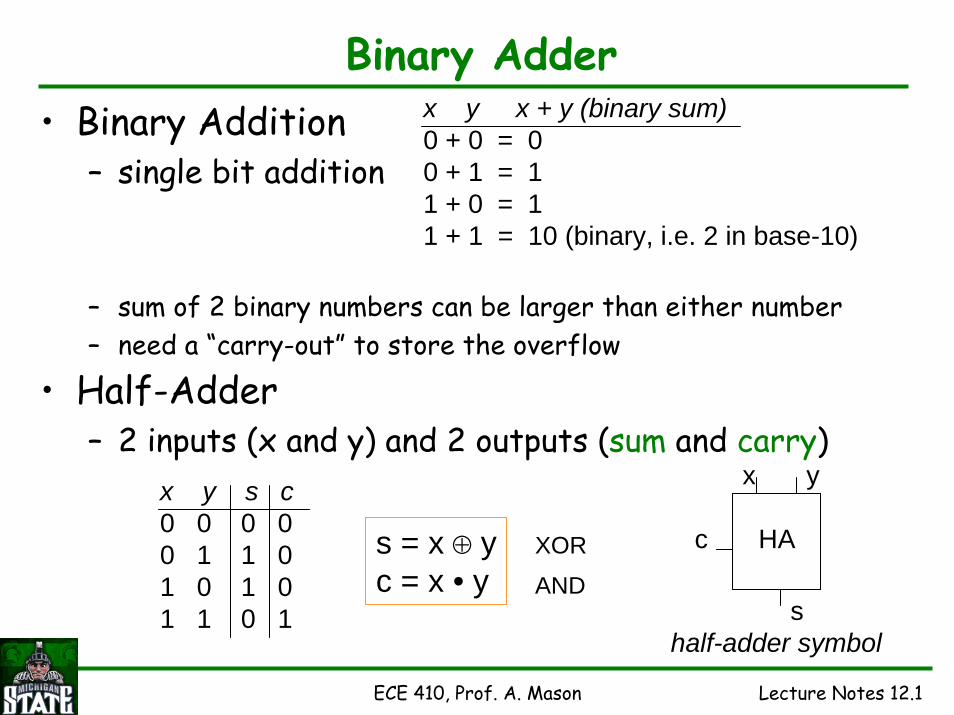
Binary Adder• Binary Addition
– single bit addition
– sum of 2 binary numbers can be larger than either number– need a “carry-out” to store the overflow
• Half-Adder– 2 inputs (x and y) and 2 outputs (sum and carry)
x y x + y (binary sum)0 + 0 = 00 + 1 = 11 + 0 = 11 + 1 = 10 (binary, i.e. 2 in base-10)
x y s c0 0 0 00 1 1 01 0 1 01 1 0 1
s = x ⊕ yc = x • y
XOR
AND
HA
x y
c
shalf-adder symbol

ECE 410, Prof. A. Mason Lecture Notes 12.2
Half-Adder Circuits• Simple Logic
– using XOR gate
• Most Basic Logic– NAND and NOR only circuits
x y s c0 0 0 00 1 1 01 0 1 01 1 0 1
s = x ⊕ yc = x • y
Take-home Questions:Which of these 3 half-adders will be fastest? slowest? why??Which has fewest transistors? Which transition has the critical delay?

ECE 410, Prof. A. Mason Lecture Notes 12.3
Full-Adder• When adding more than one bit, must consider
the carry of the previous bit– full-adder has a “carry-in” input
• Full-Adder Equation
• Full-Adder Truth Table
ciai
+ bici+1 si
for every i-th bitcarry-in+ a+ b= carry-out, sum
ai bi ci s ci+10 0 0 0 00 1 0 1 01 0 0 1 01 1 0 0 10 0 1 1 00 1 1 0 11 0 1 0 11 1 1 1 1
si = ai ⊕ bi ⊕ cici+1 = ai • bi + ci • (ai ⊕ bi)
ci+1 = ai • bi + ci • (ai + bi)
if not trying to ‘reuse’ the ai ⊕ biterm from sum, can write
FA+
ai
full-adder symbol
bi
cici+1
si

ECE 410, Prof. A. Mason Lecture Notes 12.4
Full-Adder Circuits
• XOR-based FA
• Other FA Circuits– a few others options are covered in the textbook
• HA-based FA
Full-Adder Equations: si = ai ⊕ bi ⊕ ci and ci+1 = ai • bi + ci • (ai ⊕ bi)
ECE 410, Prof. A. Mason Lecture Notes 12.5
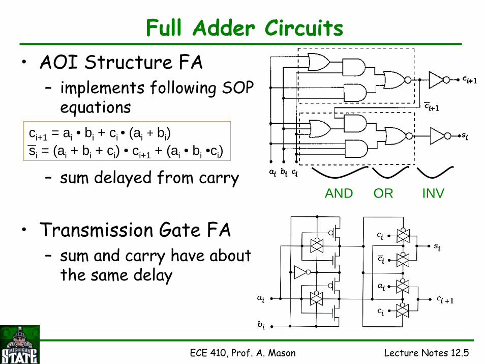
Full Adder Circuits• AOI Structure FA
– implements following SOP equations
– sum delayed from carry
• Transmission Gate FA– sum and carry have about
the same delay
AND OR INV
ci+1 = ai • bi + ci • (ai + bi)si = (ai + bi + ci) • ci+1 + (ai • bi •ci)

ECE 410, Prof. A. Mason Lecture Notes 12.6
Full Adder in CMOS• Consider nMOS logic for c_out
– two “paths” to ground
• Mirror CMOS Full Adder– carry out circuit
ci+1 = ai • bi + ci • (ai + bi)
– complete circuit
ai=bi=0ci=0 andai+bi=0
ci=1 andai+bi=1 ai=bi=1

ECE 410, Prof. A. Mason Lecture Notes 12.7
FA Using 2:1 MUX• If we re-arrange the FA truth table
– can simplify the output (sum, carry) expressions
• Implementation– use an XOR to make the decision (a⊕b=0?)– use a 2:1 MUX to select which equation/value of sum
and carry to pass to the output
ai bi ci a ⊕ b s ci+10 0 0 0 0 01 1 0 0 0 10 0 1 0 1 01 1 1 0 1 10 1 0 1 1 01 0 0 1 1 00 1 1 1 0 11 0 1 1 0 1
If (A ⊕ B = 0), SUM=Cin; Cout=A;Else, SUM=Cin_bar; Cout=Cin;
AB
CinCin_bar
ACin
Sum
Cout
A ⊕ BPartial Schematiccan you figure out
the details?
ECE 410, Prof. A. Mason Lecture Notes 12.8
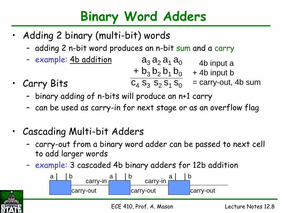
Binary Word Adders• Adding 2 binary (multi-bit) words
– adding 2 n-bit word produces an n-bit sum and a carry– example: 4b addition
• Carry Bits– binary adding of n-bits will produce an n+1 carry– can be used as carry-in for next stage or as an overflow flag
• Cascading Multi-bit Adders– carry-out from a binary word adder can be passed to next cell
to add larger words– example: 3 cascaded 4b binary adders for 12b addition
a3 a2 a1 a0+ b3 b2 b1 b0c4 s3 s2 s1 s0
4b input a+ 4b input b= carry-out, 4b sum
a b
carry-out
a b
carry-out
a bcarry-in
carry-outcarry-in
ECE 410, Prof. A. Mason Lecture Notes 12.9
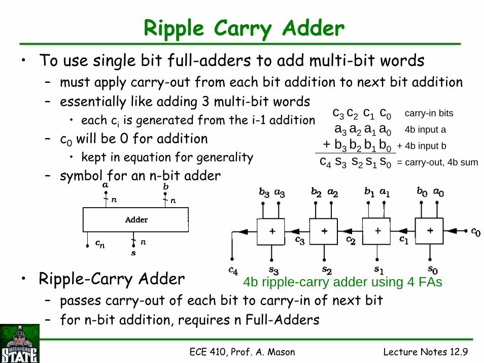
Ripple Carry Adder• To use single bit full-adders to add multi-bit words
– must apply carry-out from each bit addition to next bit addition– essentially like adding 3 multi-bit words
• each ci is generated from the i-1 addition– c0 will be 0 for addition
• kept in equation for generality– symbol for an n-bit adder
• Ripple-Carry Adder– passes carry-out of each bit to carry-in of next bit– for n-bit addition, requires n Full-Adders
c3 c2 c1 c0a3 a2 a1 a0
+ b3 b2 b1 b0c4 s3 s2 s1 s0
carry-in bits
4b input a
+ 4b input b
= carry-out, 4b sum
4b ripple-carry adder using 4 FAs

ECE 410, Prof. A. Mason Lecture Notes 12.10
Adder/Subtractor using R-C Adders• Subtraction using 2’s complements
– 2’s complement of X: X2s = X+1• invert and add 1
– Subtraction via addition: Y - X = Y + X2s
• R-C Adder/Subtactor Cell– control line, add_sub: 0 = add, 1 = subtract– XOR used to pass (add_sub=1) or invert (add_sub=0)– set first carry-in, c0, to 1 will add 1 for 2’s complement
b
b
a = add_sub

ECE 410, Prof. A. Mason Lecture Notes 12.11
Ripple-Carry Adders in CMOS• Simple to implement and connect for multi-bit addition
– but, they are very slow• Worse-case delays in R-C Adders
– each bit in the cascade requires carry-out from the previous bit• major speed limitation of R-C Adders
– delay depends somewhat on the type of FA implemented– general assumptions
• worst delay in an FA is the sum– but carry is more important due to cascade structure
• total delay is sum of delays to pass carry to final stage• total delay for n-input R-C adder
tn = td(a0,b0 ⇒ c1) + (n-2) td(cin ⇒ cout) + td(cin ⇒ sn-1)
first stage delay: inputs to carry-outmiddle stage (n-2) delay: carry-in to carry-outlast stage delay: carry-in to sum
basic FAcircuit

ECE 410, Prof. A. Mason Lecture Notes 12.12
Carry Look-Ahead Adder• CLA designed to overcome delay issue in R-C Adders
– eliminates the ripple (cascading) effect of the carry bits• Algorithm based calculating all carry terms at once• Introduces generate and propagate signals
– rewrite ci+1 = ai • bi + ci • (ai ⊕ bi) ci+1 = gi + ci • pi• generate term, gi = ai • bi
• propagate term, pi = ai ⊕ bi
– approach: evaluate all gi and pi terms and use them to calculate all carry terms without waiting for a carry-out ripple
• All sum terms evaluated at once– the sum of each bit is: si = pi ⊕ ci
• Pros and Cons– no cascade delays; outputs expressed in terms of inputs only– requires complex circuits for higher bit-order adders (next slide)

ECE 410, Prof. A. Mason Lecture Notes 12.13
Logic Circuits for a 4b CLA Adder•Carry-out expressions for 4b CLA
– c1 = g0 + c0•p0, c2 = g1 + c1•p1, c3 = g2 + c2•p2, c4 = g3 + c3•p3
• Expressed only in terms of known inputs– c2 = g1 + p1 • (g0 + c0•p0)– c3 = g2 + p2 • [g1 + p1 • (g0 + c0•p0)]– c4 = g3 + p3 • {g2 + p2 • [g1 + p1 • (g0 + c0•p0)]}– nested Sum-of-Products expressions– gets more complex for higher bit adders
• Sums obtained by an XOR with carries
gi = ai • bipi = ai ⊕ bi
simple
complex
ECE 410, Prof. A. Mason Lecture Notes 12.14
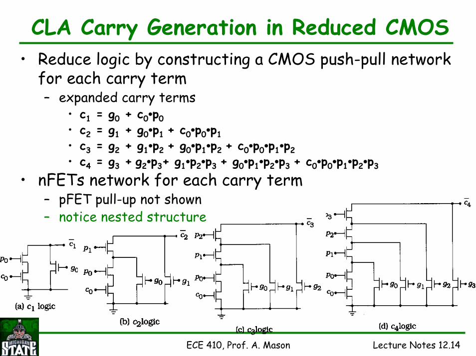
CLA Carry Generation in Reduced CMOS• Reduce logic by constructing a CMOS push-pull network
for each carry term– expanded carry terms
• c1 = g0 + c0•p0• c2 = g1 + g0•p1 + c0•p0•p1• c3 = g2 + g1•p2 + g0•p1•p2 + c0•p0•p1•p2 • c4 = g3 + g2•p3+ g1•p2•p3 + g0•p1•p2•p3 + c0•p0•p1•p2•p3
• nFETs network for each carry term– pFET pull-up not shown– notice nested structure
ECE 410, Prof. A. Mason Lecture Notes 12.15
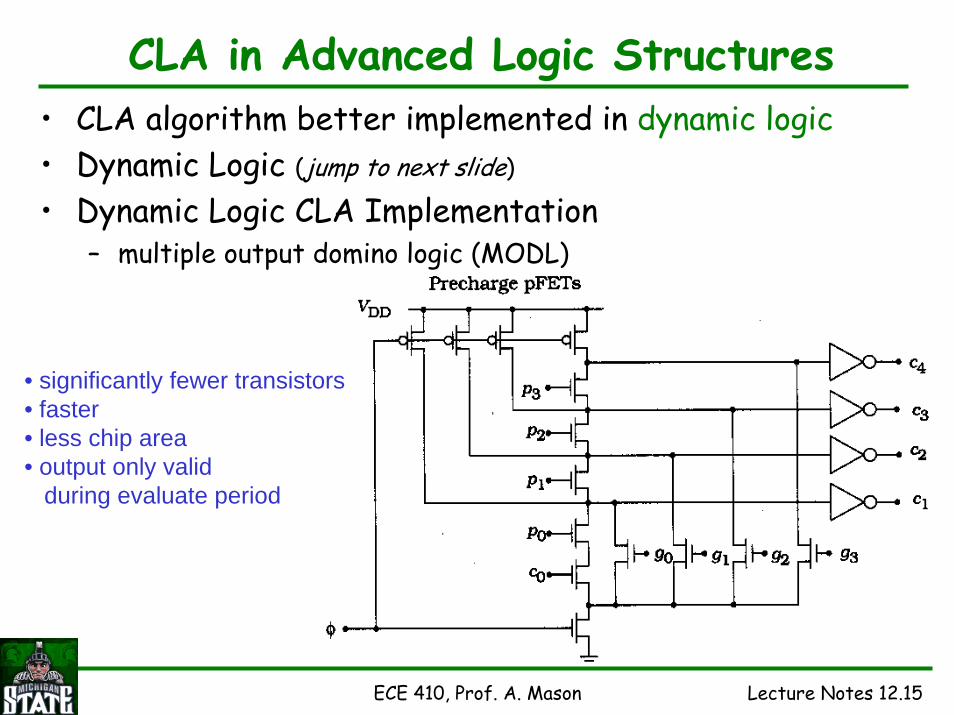
CLA in Advanced Logic Structures• CLA algorithm better implemented in dynamic logic• Dynamic Logic (jump to next slide)
• Dynamic Logic CLA Implementation– multiple output domino logic (MODL)
• significantly fewer transistors• faster• less chip area• output only valid
during evaluate period

ECE 410, Prof. A. Mason Lecture Notes 12.16
Dynamic Logic –Quick Look• Advantages: fewer transistors & less power consumption• General dynamic logic gate
– nFET logic evaluation network– clocked “precharge” pull up pFET– clocked disabling nFET
• Precharge stage– clock-gated pull-up precharges output high– logic array disabled
• Evaluation stage– precharge pull-up disabled– logic array enabled & if true, discharges output
• Dynamic operation: output not always valid
generic dynamiclogic gate

ECE 410, Prof. A. Mason Lecture Notes 12.17
Manchester Carry Generation Concept• Alternative structure for carry evaluation
– define carry in terms of control signals such that• only one control is active at a given time
– implement in switch-logic• Consider single bit FA truth table
– p OR g is high in 6 of 8 logic states• p and g are not high at the same time
– introduce carry-kill, k• on/high when neither p or g is high• carry_out always 0 when k=1
– only one control signal (p, g, k) is active for each state
ai bi ci ci+10 0 0 00 1 0 01 0 0 01 1 0 10 0 1 00 1 1 11 0 1 11 1 1 1
pi gi ki0 0 11 0 01 0 00 1 00 0 11 0 01 0 00 1 0
generate gi = ai • bi
propagate pi = ai ⊕ bi
carry-kill ki = ai + bi
ECE 410, Prof. A. Mason Lecture Notes 12.18
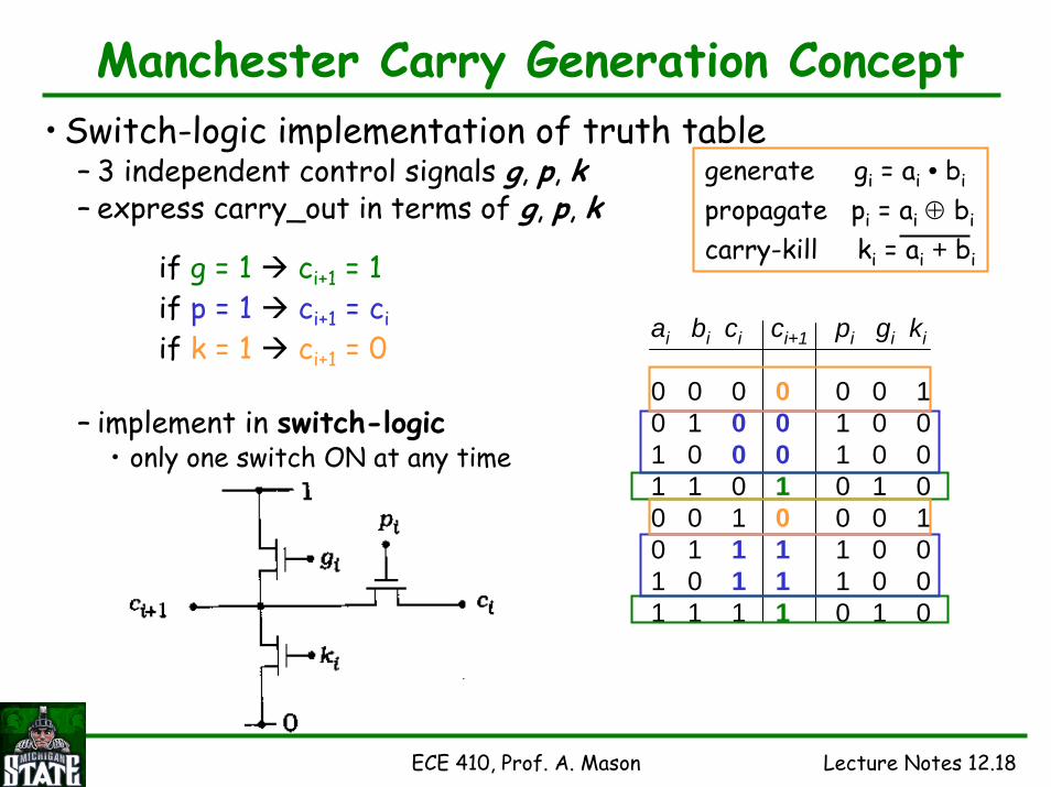
Manchester Carry Generation Concept• Switch-logic implementation of truth table
– 3 independent control signals g, p, k– express carry_out in terms of g, p, k
– implement in switch-logic• only one switch ON at any time
ai bi ci ci+1
0 0 0 00 1 0 01 0 0 01 1 0 10 0 1 00 1 1 11 0 1 11 1 1 1
pi gi ki
0 0 11 0 01 0 00 1 00 0 11 0 01 0 00 1 0
if g = 1 ci+1 = 1if p = 1 ci+1 = ciif k = 1 ci+1 = 0
generate gi = ai • bi
propagate pi = ai ⊕ bi
carry-kill ki = ai + bi
ECE 410, Prof. A. Mason Lecture Notes 12.19
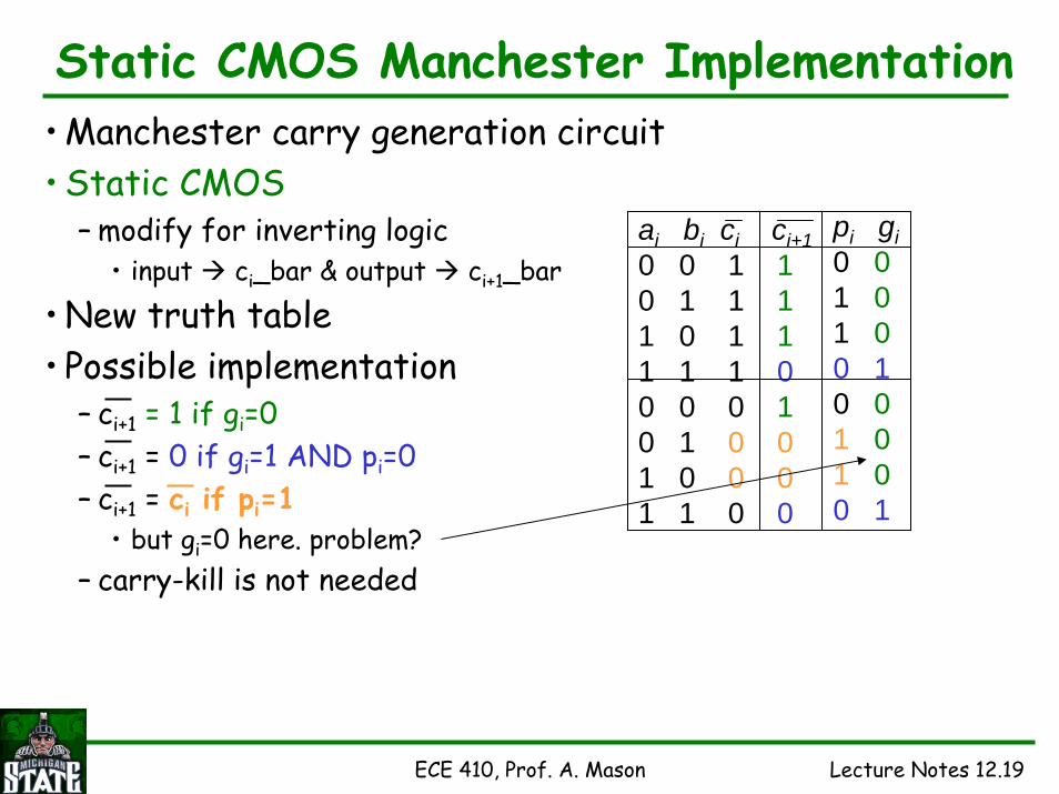
Static CMOS Manchester Implementation• Manchester carry generation circuit• Static CMOS
– modify for inverting logic• input ci_bar & output ci+1_bar
• New truth table• Possible implementation
– ci+1 = 1 if gi=0– ci+1 = 0 if gi=1 AND pi=0– ci+1 = ci if pi=1
• but gi=0 here. problem?– carry-kill is not needed
ai bi ci ci+10 0 1 10 1 1 11 0 1 11 1 1 00 0 0 10 1 0 01 0 0 01 1 0 0
pi gi0 01 01 00 10 01 01 00 1

ECE 410, Prof. A. Mason Lecture Notes 12.20
Static CMOS Manchester Implementation• Textbook Circuit Implementation
– ci+1 = 1 if gi=0– ci+1 = 0 if gi=1 AND pi=0– ci+1 = ci if pi=1
– error• when gi=0, pi=1, ci=0, ci+1 0• pulled low through M1• but M4 pulls it high
• Possible Correction?– insert switch in pull-up path to disable when ci=0– solves error when gi=0, pi=1, ci=0 ci+1=0– but introduces error when gi=0, pi=1, ci=0 ci+1=1
• M4 can not pull high since new nMOS cuts off path
staticCMOS
from textbook
ci
ai bi ci ci+10 0 1 10 1 1 11 0 1 11 1 1 00 0 0 10 1 0 01 0 0 01 1 0 0
pi gi0 0 1 0 1 00 10 0 1 01 00 1

ECE 410, Prof. A. Mason Lecture Notes 12.21
pi
gi
gi
cici+1
Manchester Implementation
– truth table organized by pi• if pi = 0
– ci+1 = gi (NOT gi)– block ci, pass VDD or GND
• if pi = 1– ci+1 = ci– pass ci, block VDD & GND
correctedstatic
CMOSai bi ci ci+10 0 1 10 1 1 11 0 1 11 1 1 00 0 0 10 1 0 01 0 0 01 1 0 0
pi gi0 01 01 00 10 01 01 00 1
ai
0 0 1
0 0 0
1 1 1
1 1 0
0 1 1
1 0 1
0 1 0
1 0 0
bi ci ci+1 pi gi VDD GND Ci
1 0 0 act x x
1 0 0 act x x
0 0 1 x act x
0 0 1 x act x
1 1 0 x x act
1 1 0 x x act
0 1 0 x x act
0 1 0 x x act
act = activex = disabled
alternative design:- do not add pMOS M3- make W of M1 significantly larger than W of M4
Ci will override VDD
• Corrected Manchester Carry Generation Circuit
M4
M3
M2
M1

ECE 410, Prof. A. Mason Lecture Notes 12.22
Manchester Implementation• Dynamic Logic Circuit
– evaluate when φ = 1– ci+1 stays high unless
• gi = 1 (ci+1 0) or pi = 1 (ci+1 ci)
• 4b Dynamic Manchester Carry Generation– minor ripple delay– threshold drop on propagate– very few transistors
single bit carry generation indynamic logic
ai bi ci ci+10 0 1 10 1 1 11 0 1 11 1 1 00 0 0 10 1 0 01 0 0 01 1 0 0
pi gi0 0 1 0 1 0 0 1 0 0 1 0 1 0 0 1
internal output, ci+1dynamically pulled high
propagatepulled low (generate)

ECE 410, Prof. A. Mason Lecture Notes 12.23
CLA for Wide Words• number of terms in the carry equation increases with
the width of the binary word to be added– gets overwhelming (and slow) with large binary words
• one method is to break wide adders into smaller blocks – e.g., use 4b blocks (4b is common, but could be any number)– must create block generate and propagate signals to carry
information to the next block• g[i,i+3] = gi+3 + gi+2•pi+3 + gi+1•pi+2•pi+3 + gi•pi+1•pi+2•pi+3
• p[i,i+3] = pi•pi+1•pi+2•pi+3• for block i thru i+3 of an n-sized adder

ECE 410, Prof. A. Mason Lecture Notes 12.24
16b Adder Using 4b CLA Blocks
• Create SUMs from outputs of this circuit

ECE 410, Prof. A. Mason Lecture Notes 12.25
Other Adder Implementations• Alternative implementations for high-speed adders• Carry-Skip Adder
– quickly generate a carry under certain conditions and skip the carry-generation block
• recall ci+1 = gi + ci•pi, gi = ai • bi, pi = ai ⊕ bi• note generation of pi is more complex (XOR) than gi (AND)
– so, generate pi and check cipi case, skip gi generation if cipi = 1
• Carry-Select Adder– uses multiple adder blocks to increase speed– take a lot of chip area
• Carry-Save Adder– parallel FA, 3 inputs and 2 outputs– does not add carry-out to next bit (thus no ripple)
• carry is saved for use by other blocks– useful for adding more than 2 numbers

ECE 410, Prof. A. Mason Lecture Notes 12.26
Fully Differential Full Adder• (a) sum-generate circuit• (b) carry generate circuit
pMOS
nMOS pMOS
nMOS

ECE 410, Prof. A. Mason Lecture Notes 12.27
Multiplier Basics• Single-Bit Binary Multiplication
– 0 x 0 = 0, 0 x 1 = 0, 1 x 0 = 0, 1 x 1 = 1– same result as logic AND operation (1b output, no carry!)
• Multiple-Bit Multiplication– n-bit word TIMES an n-bit word give 2n-bit product– 4b example
• 16 single-bit multiplies– multiply each bit of a by each bit of b
• shift products for summingnote: can multiply by 2 by shifting the word to the left by one, multiply by 4 by left-shift twice, 8 three times, etc.

ECE 410, Prof. A. Mason Lecture Notes 12.28
Implementing Multiplier Circuits• Multiplication Sequence
– organization of ANDs and ADDs
• 4x4 ArrayMultiplier Circuit
– 8b output

ECE 410, Prof. A. Mason Lecture Notes 12.29
• Signed Numbers– 2’s complement
• Booth Encoding– evaluate number 2-bits at a time– generate ‘action’ based on 2-bit sequence
+m = m–m = 2 – m
Ex: 3-bit signed numbers3 = 0 1 12+3 = 5 = 2- (-3)=> 1 0 1 = -3
Signed Multiplication: Booth Encoding
0 1 1 0 1 (0) 1 0 -1 1 -1
-1: a sequence of “ 1 0”0: no change in sequence1: a sequence of “ 0 1”
0 1 1 0 1 = (13)10 = [ 1*24 + 0*23 –1*22 + 1*21 –1*20]
Benefit: Number of shift-add reduces if long seq. of “1” or “0”

ECE 410, Prof. A. Mason Lecture Notes 12.30
4b x 4b Booth MultiplicationMultiply m x r: A = m3 m2 m1 m0 x r3 r2 r1 r0
Rules: Start with product A = 0Examine rn, rn-10 0 : shift R right0 1 : add M (A+M)
shift A right1 0 : sub M (A-M)
shift A right1 1 : shift A right
Ex : 0 1 0 1 x 1 0 1 1 ( 5* -5 = - 25)n rn rn-1 Action A = 0 0 0 0
0 1 0 Sub M (A-M) 1 0 1 1
Shift Rt 1 1 0 1 1
1 1 1 Shift Rt 1 1 1 0 1 1
2 0 1 Add M (A+M) 0 0 1 1 1 1
Shift Rt 0 0 0 1 1 1 1
3 1 0 Sub M (A-M) 1 1 0 0 1 1 1 =-25
1 1 1 0 1 10 1 0 10 0 1 1 1 1
0 0 0 1 1 1 11 0 1 11 1 0 0 1 1 1

ECE 410, Prof. A. Mason Lecture Notes 12.31
Arithmetic/Logic Unit Structure• ALU performs basic arithmetic and logic
functions in a single block– core unit in a microprocessor
• Basic n-bit ALU– Inputs
• 2 n-bit inputs• carry in• function selects
– Outputs• 1 n-bit result• carry out• status outputs
– minus, zero, etc.Status

ECE 410, Prof. A. Mason Lecture Notes 12.32
ALU Arithmetic Components• ALU Components
– Arithmetic Block– Logic Block– Date Movement
• sometimes done in register file
• Arithmetic Block– implements arithmetic functions– add– subtract– increment/decrement– sometimes
• multiply• divide
Example 4b Arithmetic Block

ECE 410, Prof. A. Mason Lecture Notes 12.33
ALU Logic Components• Logic Block
– implements logic functions– NOT– AND– OR– XOR
• Date Movement– somewhere in the ALU
• or in the register file– shift– rotate
Example 1-bit Logic Block

ECE 410, Prof. A. Mason Lecture Notes 12.34
Example ALU Organization & Function• Example ALU Bit Slice
– implementation of one bit
• Example Function Table
function set fora simple ALU
function determinedby select inputs