bill dawber and bill wallace qinetiq portsdown technology ... · bill dawber and bill wallace...
TRANSCRIPT

The advanced radar technology integrated system testbed (ARTIST) and the need for cognitive radar management and control
Bill Dawber and Bill Wallace
QinetiQ Portsdown Technology Park, Southwick Road, Cosham, Portsmouth, PO6 3RU
Abstract
This paper describes the joint UK/US advanced radar technology integrated system testbed (ARTIST) naval radar technology demonstrator programme, which has just completed a ten month trials period in the USA at Wallops Island. Two active electronically scanned phased array radar systems have been developed under the programme, one produced by the UK team of QinetiQ, BAE and Roke and a second US system built by Lockheed Martin. The radar environment proved to be extremely challenging for both ARTIST radars with widely varying clutter, propagation and electromagnetic interference conditions. Surveillance and tracking waveforms and signal processing have been gradually improved over the trials period to better match the complex environment and individual trials needs. However, for an in-service system a team of radar engineers will not be available to perform this process and automatic, intelligent optimisation of the many radar parameters, including scheduling, will be highly desirable in order to maximise the latent performance available from this class of radar in future systems. A proposed architecture for cognitive, self adaptive radar resource management and control within ARTIST is presented together with preliminary analysis highlighting some of the potential benefits of this approach.
Introduction
ARTIST is a joint UK/US programme to de-risk technologies for next generation active electronically scanned surface radar systems. Two S-band single faced active electronically scanned phased array radar systems have been developed under the programme, one produced by the UK team of QinetiQ, BAE and Roke and a second US system primed by Lockheed Martin.
UK ARTIST is a flexible multifunction radar testbed to research and understand advanced techniques and technologies to improve capabilities in tactical picture compilation particularly against difficult targets in stressing environments.
The UK programme is focussed on operation in the littoral particularly against small, difficult, targets in dense clutter and in the presence of both intentional and unintentional interference.
UK ARTIST utilises the antenna and elements of radar control from the MESAR2 technology demonstrator [1] but with all new waveform generation, receivers, signal processing and data logging. The key technologies addressed by the programme are;
• Ultra stable waveform generation to support high levels of clutter improvement factor (CIF)
• Small, high dynamic range receivers
• A flexible, extensible, COTS based signal processing environment with real time adaptive processor allocation
• Adaptive signal processing for small target detection in clutter
• Signal processing for pulsed electromagnetic interference (EMI) mitigation

• High resolution range and Doppler capability to support non cooperative target recognition (NCTR)
• Digital adaptive beamforming with ultra high levels of cancellation
• Circular, dual rotation and orthogonal monopulse processing
• Extensive data logging to support future research
UK ARTIST has been designed to provide direct comparison of performance with and without the new ARTIST technologies and techniques, by incorporating both ‘baseline’ and ‘enhanced’ signal processing and waveform and signal generation hardware. Trials have generally been repeated in both baseline and enhanced states so that the system level impact of ARTIST technologies can be directly inferred.
The UK programme commenced in October 2003 with the radar completing integration at Cowes in the UK in January 2010. Prior to shipping to Wallops Island, static trials were performed from the Cowes site using targets of opportunity and electronic targets produced by the radar research target generator (RRTG), a high fidelity, calibrated, digital false target generator developed specifically for this programme. These trials confirmed the basic radar performance characteristics with the radar meeting or exceeding its critical design goals. In particular, the radar has exceptionally high dynamic range and CIF, representing a very significant improvement over previous systems.
Following these preliminary trials at Cowes the UK radar was shipped to the USA for joint trials alongside the US ARTIST system at Wallops Island, Virginia.
The US trials programme
Figure 1 - UK and US ARTIST radars installed at Wallops Island (UK ARTIST is
highest radar)
Figure 1 shows the UK and US radars installed at the Wallops Island facility. The radars are mounted on towers to provide representative operational heights above sea level for UK and US navy ships, respectively.
A wide range of dedicated target assets were provided to test the radars against including;
• Fixed wing jets
• Light aircraft
• Uninhabited air vehicles (UAV)s
• Helicopters
• Towed sea-skimming targets
• Jet skis
• Rigid inflatable boats
• High fidelity electronic targets
• Sounding rockets
• Aerosondes

In addition, a large number of targets of opportunity were also utilised, including airliners, fishing boats and satellites. All of the dedicated trials were conducted with extensive ground truth and environmental monitoring, including measurements of refractivity profiles, wave rider buoys and meteorological data sets.
The trials were grouped in to 7 main types;
• Setting to work and clutter characterisation
• Mutual interference
• Feature measurement
• Small targets in land clutter
• Small targets in sea clutter
• Small targets in chaff
• Jamming trials
• Sea skimming targets
Setting to work and clutter characterisation
Initial setting to work trials conducted in March/April concentrated on collecting clutter data and adjusting waveforms and radar control parameters where necessary to maintain performance in the difficult conditions.
Figure 2 – Clutter data overlaid on map
Figure 2 shows an example of bottom beam short range surveillance clutter returns overlaid on a map of the Wallops island site. The radar is located just above the top of the figure at the centre of the arc. With the radar in this orientation clutter returns at the left of the field of view (lower azimuth and/or beam number) correspond to over sea and the right of the field of view (high azimuth/beam number) are overland.
Analysis of the clutter returns revealed that the radar had sufficiently high dynamic range and clutter improvement factor to allow cancellation of the clutter to the noise floor with all surveillance waveforms without the need for receive attenuation (sensitivity time control). This allows extremely high sensitivity to be achieved within the dense littoral clutter.
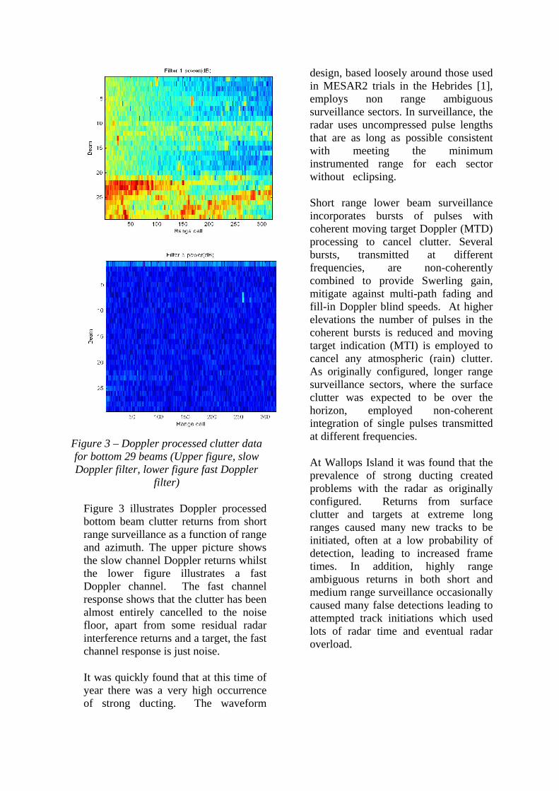
Figure 3 – Doppler processed clutter data for bottom 29 beams (Upper figure, slow Doppler filter, lower figure fast Doppler
filter)
Figure 3 illustrates Doppler processed bottom beam clutter returns from short range surveillance as a function of range and azimuth. The upper picture shows the slow channel Doppler returns whilst the lower figure illustrates a fast Doppler channel. The fast channel response shows that the clutter has been almost entirely cancelled to the noise floor, apart from some residual radar interference returns and a target, the fast channel response is just noise.
It was quickly found that at this time of year there was a very high occurrence of strong ducting. The waveform
design, based loosely around those used in MESAR2 trials in the Hebrides [1], employs non range ambiguous surveillance sectors. In surveillance, the radar uses uncompressed pulse lengths that are as long as possible consistent with meeting the minimum instrumented range for each sector without eclipsing.
Short range lower beam surveillance incorporates bursts of pulses with coherent moving target Doppler (MTD) processing to cancel clutter. Several bursts, transmitted at different frequencies, are non-coherently combined to provide Swerling gain, mitigate against multi-path fading and fill-in Doppler blind speeds. At higher elevations the number of pulses in the coherent bursts is reduced and moving target indication (MTI) is employed to cancel any atmospheric (rain) clutter. As originally configured, longer range surveillance sectors, where the surface clutter was expected to be over the horizon, employed non-coherent integration of single pulses transmitted at different frequencies.
At Wallops Island it was found that the prevalence of strong ducting created problems with the radar as originally configured. Returns from surface clutter and targets at extreme long ranges caused many new tracks to be initiated, often at a low probability of detection, leading to increased frame times. In addition, highly range ambiguous returns in both short and medium range surveillance occasionally caused many false detections leading to attempted track initiations which used lots of radar time and eventual radar overload.

Figure 4 – Clutter in lower beams, upper figure in normal propagation, lower in
ducting
Figure 4 illustrates typical pulse compressed clutter power returns as a function of range and bearing from the first pulse of each of the bottom beams of the radar. The short medium and long range sector returns have been laid out next to each other. The upper picture shows the returns on a non ducting day whilst the lower shows the returns on a day when ducting was present. Extensive regions of surface clutter returns are clearly present at ranges in excess of 200km.
Figure 5 –Bottom beam clutter returns folded out from short range surveillance
Figure 5 illustrates an example of the clutter returns folded-out from a burst of short range surveillance pulses and displayed on Cartesian coordinates. Clutter returns 18 times ambiguous are
clearly visible in this strong ducting example!
In order to overcome these issues, more guard pulses were used in the lower beams at all ranges and the medium and long range surveillance sectors were modified to incorporate longer coherent dwells with MTD processing. However, this has meant that the frame times are significantly longer than the original design.
The extreme sensitivity and dynamic range of the radar has allowed very high fidelity clutter data recordings to be made. Long coherent dwell, high Doppler resolution clutter data was gathered for off-line analysis.
Figure 6 – High resolution range-Doppler
image of rain clutter
Figure 6 illustrates an example of a range-Doppler spectrum produced from a medium range, raised beam passing through a rain cloud.
At short range some surface clutter is visible at zero Doppler and some slow moving point targets (possibly birds) can be observed at around 16-17 km. Beyond 18 km rain clutter returns dominate. The anisotropy of the rain Doppler is clearly evident illustrating the ability of this class of radar to perform meteorological data collection tasks. The figure also
demonstrates the need for range dependent adaptive Doppler filtering (ADF) [11] for optimum slow target detection in this environment.
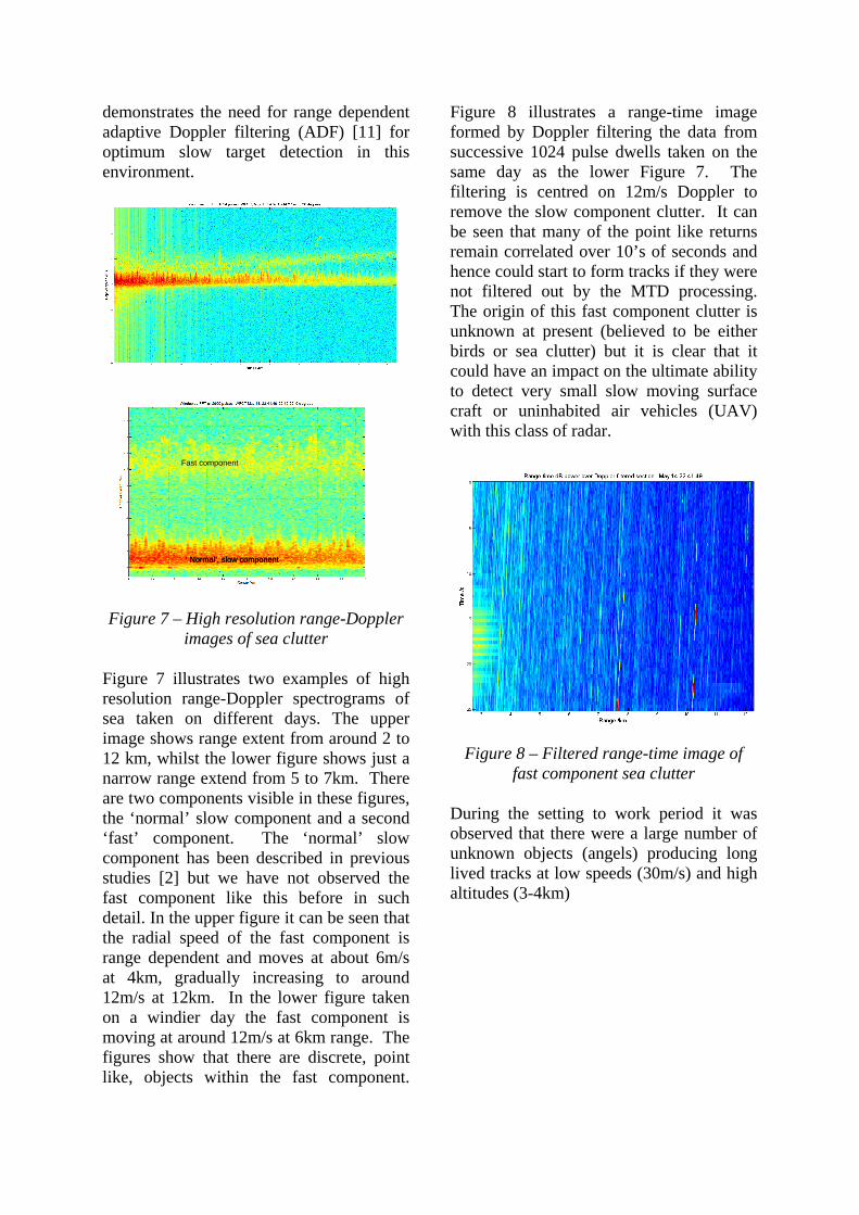
Figure 7 – High resolution range-Doppler images of sea clutter
Figure 7 illustrates two examples of high resolution range-Doppler spectrograms of sea taken on different days. The upper image shows range extent from around 2 to 12 km, whilst the lower figure shows just a narrow range extend from 5 to 7km. There are two components visible in these figures, the ‘normal’ slow component and a second ‘fast’ component. The ‘normal’ slow component has been described in previous studies [2] but we have not observed the fast component like this before in such detail. In the upper figure it can be seen that the radial speed of the fast component is range dependent and moves at about 6m/s at 4km, gradually increasing to around 12m/s at 12km. In the lower figure taken on a windier day the fast component is moving at around 12m/s at 6km range. The figures show that there are discrete, point like, objects within the fast component.
Figure 8 illustrates a range-time image formed by Doppler filtering the data from successive 1024 pulse dwells taken on the same day as the lower Figure 7. The filtering is centred on 12m/s Doppler to remove the slow component clutter. It can be seen that many of the point like returns remain correlated over 10’s of seconds and hence could start to form tracks if they were not filtered out by the MTD processing. The origin of this fast component clutter is unknown at present (believed to be either birds or sea clutter) but it is clear that it could have an impact on the ultimate ability to detect very small slow moving surface craft or uninhabited air vehicles (UAV) with this class of radar.
Figure 8 – Filtered range-time image of fast component sea clutter
During the setting to work period it was observed that there were a large number of unknown objects (angels) producing long lived tracks at low speeds (30m/s) and high altitudes (3-4km)
‘ Normal’, slow component
Fast component
‘ Normal’, slow component

Figure 9 – PPI display showing ‘angel’ tracks
Figure 9 illustrates an example of a plan position indicator (PPI) display captured when there were a large number of the ‘angels’ present. The majority of the angles are travelling in the same direction and at similar speeds and heights. High resolution range and Doppler imagery of the angles reveals that they are point like without significant Doppler components and they are now believed to be migrating birds. (Similar images taken at spring and in the fall show that the majority of angels are travelling in opposite directions at these two times, following the expected migratory behaviour)
Small surface craft in sea clutter
A number of small target trials were performed over the sea. Figure 10 illustrates pulse compressed data collected from a trial using a small surface craft as it approached radially inbound at around 25 knots (13m/s) towards the radar. The data is shown for only a small angular sector around the target position.
Figure 10 – Range time image of unfiltered data from surface craft trials
The path of the surface craft can just be made out and is highlighted on the figure. There are a number of horizontal lines produced by interference from other radars and, in addition, there are a large number of clutter objects moving at a similar speed to the inbound surface craft.
Figure 11 – Range-time image of Doppler filtered data showing surface craft and
clutter
Figure 11 shows the same data after Doppler processing to remove stationary clutter. Although some of the clutter has been removed there is still a great deal remaining due to its high speed. This fast moving clutter is highly correlated and can form tracks that can extend tens of km.
Surface craft
Surface craft

Figure 12 – Track history recorded from jet trial
Figure 12 shows an example of the tracks recorded during a trial with a jet target crossing at around 30 km range to the south using conventional MTD processing. The large number of slow tracks over the sea is clearly visible. By contrast to the surface craft trial, on this occasion the clutter tracks are mostly travelling outbound.
Figure 13 – Range-time image of fast channel surveialnce plots for jet trial
Figure 13 shows the fast plot history for half of the run (600 seconds). The many clutter tracks are clearly visible mostly travelling outbound at a similar radial velocity of approximately 25 m/s. (Note that at ranges less than 12 km the conventional MTD processing applies a wider Doppler clutter notch, greatly reducing the amount of clutter breakthrough, but also increasing the minimum detectable velocity)
Due to the very large number of these slow moving tracks, in order to obtain a clear operational picture without degrading the radar sensitivity for small, slow moving targets, it will be highly beneficial to apply some kind of semi automatic track discrimination to separate wanted, man made, craft (low altitude UAV and surface boats) from natural clutter (birds, sea clutter etc). Track kinematics (speed and estimated height) can provide some indication of classification but are not reliable means of dicsriminating the clutter from targets. Further radar features can be collected to assist in the classification. In particular, high resolution range and Doppler profiles should provide significantly higher confidence in classification.
Feature measurement in ARTIST
UK ARTIST provides the ability to extract high resolution range and Doppler profiles from targets under track. Currently this can be performed automatically for all tracks within a certain region or with certain kinematic properties or by the operator selecting a track of interest.
Figure 14 – PPI display from high range resolution (HRR) trial

Repeater pod
Aircraft
Figure 15 – HRR profiles
Figure 14 shows a PPI display taken from a trial using an aircraft with an electronic repeater pod, which produces a synthetic point target at longer range behind the aircraft. A blow up around the aircraft position is shown, indicating the tracks from which high resolution range (HRR) profiles have been produced. The HRR profiles are shown in Figure 15. Automatic estimation of number of scatterers and target length (in the radial direction) is provided.
Figure 16 – High resolution Doppler spectrogram of helicopter
Figure 16 shows a high resolution Doppler spectrogram taken from a helicopter. The blade flashes are clearly visible from both main and tail rotors.
High resolution feature measurement dwells take considerably longer time to transmit than conventional track updates and so feature measurement data collection can usually only be applied to a relatively small number of tracks without causing radar overload.
Current radar control architecture
UK ARTIST employs the old legacy radar control architecture from the MESAR programme [3] as is illustrated in a simplified form in Figure 17. The radar control is based around a ‘time balancing’ algorithm [4] which takes task requests from the surveillance, tracker and other looks (cued search, feature measurement requests, calibration etc) modules and schedules them according to their relative priorities and how late they are.

Figure 17 – Radar resource management and control in ARTIST
Tracking tasks are optimised to maintain a desired probability of track drop (pulse, length, number of pulses, PRF and update rate are all varied) using rules based logic, however, surveillance tasks and other looks are non adaptive. This lack of surveillance adaptively means that ‘worst case’ waveforms must be applied continuously (i.e. strong clutter and ducting), requiring long dwells which are highly inefficient. In addition, because all tracking tasks are given the same priority, when there are many contacts under track, surveillance frame times become excessive and the radar can overload.
These problems can be exacerbated when using enhanced signal processing chains with increased sensitivity to detect small, slow targets, as this also increases the number of tracks from naturally occurring slow moving contacts.
During the conduct of the US trials these problems were mitigated on several occasions by raising detection thresholds, to reduce the number of clutter tracks, or, by restricting the tracking coverage volume of the radar.
Clearly these mitigation approaches are highly undesirable. In order to fully exploit the increased sensitivity and discrimination capabilities of this class of radar a more intelligent, efficient radar resource management and control system is required.
Environmentally aware, self adaptive radar management and control
Figure 18 – Concept for environmentally aware, self adaptive radar control
Figure 18 illustrates the concept for environmentally aware, self adaptive radar control. The required mission of the radar is defined by the platform and force command. Knowledge of the environment (targets, clutter and propagation, interference etc) is acquired using previous returns from the radar itself as well as from other sensors (e.g. navigation, meteorological) and encyclopaedic data sources (e.g. mapping data). The radar manager uses this environmental awareness to determine what tasks need to be undertaken and how well they need to perform. Each task is then optimised to the current environment to achieve the desired performance in the minimum time. Optimised tasks are scheduled and the processed returns are analysed to determine how well the radar performed and to update the environmental picture.
Figure courtesy BAE systems

Proposed implementation in ARTIST
To address the issues described in the previous section, a modified radar control architecture has been proposed for ARTIST as illustrated in Figure 19.
Figure 19 – Proposed adaptive radar resource management for ARTIST
The design incorporates all of the functionality of the environmentally aware, self adaptive radar control described in Figure 18, whilst maintaining the core architecture of the MESAR radar control.
Key features are;
• Required performance is input to the radar via a ‘mission planning tool’, which allows tracking coverage volumes and track quality metrics to be defined.
o Where required performance cannot be achieved, the strategy for required performance degradation is defined
• ‘Radar self assessment’ performs clutter mapping and duct inversion [8-10]. Surveillance performance is estimated using synthetic target
injection [11]. This information can be displayed to the user
• Tracks are individually prioritised using a fuzzy logic scheme as described in [5, 6]. Low priority tracks are assigned lower levels of required performance and hence need less occupancy.
o Tracks of a certain priority and kinematics will have feature measurement tasks performed to support classification
• Surveillance sectors are adaptive based on homogenous regions from the clutter map.
o Waveforms in each sector are optimised to achieve desired performance in that clutter and propagation environment
• Load control compares estimated achieved and required performance and applies reduction/enhancement of requirements according to strategy.
This new design is expected to yield significant savings in the occupancy required for both surveillance and tracking. This will allow a high proportion of tracks to be assessed using high resolution feature measurement tasks. The architecture also provides the operator with the ability to define the mission of the day in terms of track performance coverage and quality and to asses how well the radar is achieving those goals.
Summary
The ARTIST programme has demonstrated new technologies for future surface radar systems representing a step change in

performance and sensitivity when operating in highly cluttered, littoral environments. This improvement in sensitivity coupled with high fidelity data recording is revealing new and complex features in the environment.
The increased sensitivity of ARTIST allows many more naturally occurring, real word objects, which are not of military interest, to be detected and tracked, potentially leading to both radar and operator overload.
An environmentally aware, self adaptive radar architecture has been proposed to address these issues to fully exploit the latent capability from this class of radar.
Self adaptive radar control and task optimisation represents a move away from traditional radar design philosophy where waveforms and processing are fixed and designed to meet the customer requirements in a ‘worst case’ environment. The performance of self adaptive radar systems explicitly becomes a function of the operational environment and will need new processes to be developed for procurement and acceptance.
Acknowledgements
This work was funded by the Ministry of Defence under contract AWE/N06502.
The authors would like to thank the support of the whole of the ARTIST team and especially to Martin Widgery for his support and encouragement throughout the programme.
References
1. S Penney, ‘Electronically scanned radar promises anti-ballistic missile solutions’ Flight international, 2-8 June 1999, pp 43
2. W Dawber, Analysis of Spectrum Variability in Sea Clutter’ Radar 2002 Conf. publication no 490 pg 444-448
3. W.K. Stafford, ‘Real time control of a multifunction electronically scanned radar (MESAR)’, in Proc. IEE Colloquium Real Time Management Adaptive Radars, June 1990, pp. 7/1–7/5.
4. J.M. Butler, “Multi-function radar tracking and control,” Ph.D. dissertation, University College London, 1998.
5. S.L.C. Miranda, C.J. Baker, K. Woodbridge, and H.D. Griffiths, “Phased array radar resource management: A comparison of scheduling algorithms,” in Proc. 2004 IEEE Radar Conf., Philadelphia, USA, 2004, pp. 79–84.
6. Vine M.T., Fuzzy Logic in Radar Resource Management, IEE Multifunction Radar and Sonar Management Techniques, 26th November 2001, pp5/1—5/4.
7. S.L.C. Miranda, C. Baker, K. Woodbridge, and H.D. Griffiths, ‘Phased array radar resource management: A fuzzy logic approach for prioritization of radar tasks and sectors of surveillance’, in Proc. Radar 2004 Conf., Toulouse, France, Oct. 2004.
8. W Dawber and J Branson, ‘Environmentally Aware Radar’ Journal of Defence Science, Vol. 7, No. 2, Pg 157-161
9. W Dawber, J Branson and S Wooding, ‘Modelling of the Littoral Environment for real-time radar performance assessment’ Radar 2002 Conf. publication no 490 Pg 41-47
10. W Dawber and P Donnelly, ‘Modelling and Optimisation of Adaptive MFRs’ Invited Paper, IEE Radar and Sonar Navigation Systems PN Conf Proceedings 01/173

11. W Dawber and N Harwood, ‘Comparison of Doppler clutter cancellation techniques for naval multi-function radars’, IEE Proc-Radar Sonar Navigation, Vol 150 No1