bid document for - welcome to dfccil doc sone junction arrangement part 1-4... · bid document for...
TRANSCRIPT
Page 1 of 289
BID DOCUMENT FORDesign and Construction of Formation in Embankments/Cuttingsincluding blanketing, Viaducts, Rail Flyover, Bridges (Major, Minor& RUBs), Supply and Spreading of Ballast and other relatedinfrastructural works for double track electrified railway line onDesign Build Lump Sum Basis from Howrah end approach of DFCSone bridge to Chirailapathu station of IR towards Howrah & toNew Sonnagar station towards Garhwa and at Dehri-on-Sone yardfrom Km. 3.16 to Km. 5.38 in connection with Eastern DedicatedFreight Corridor in the state of Bihar in India.
CIVIL AND STRUCTURES CONTRACT PACKAGE
Issued on: 12.10.2015
Bid DocumentNo.: HQ/EN/EC/SEB JN.Works
PART -1 to PART-4
Employer:
DEDICATED FREIGHT CORRIDOR CORPORATION OF INDIALIMITED
(A GOVERNMENT OF INDIA ENTERPRISE)
MINISTRY OF RAILWAYSCOUNTRY: INDIA
Page 2 of 289
INVITATION FOR BIDDEDICATED FREIGHT CORRIDOR CORPORATION OF INDIA LIMITED
Our Ref.: Date
ToFrom
___________________________ Managing Director,___________________________ DFCCIL___________________________ 5TH Floor, Pragati Maidan Metro
Station Building ComplexNew Delhi-110001.
______________________________________________________
Design and Construction of Formation in Embankments/Cuttings includingblanketing, Viaducts, Rail Flyover, Bridges (Major, Minor & RUBs), Supplyand Spreading of Ballast and other related infrastructural works for doubletrack electrified railway line on Design Build Lump Sum Basis from Howrahend approach of DFC Sone bridge to Chirailapathu station of IR towardsHowrah & to New Sonnagar station towards Garhwa and at Dehri-on-Soneyard from Km. 3.16 to Km. 5.38 in connection with Eastern Dedicated FreightCorridor in the state of Bihar in India.
This Bidding process is open for pre-qualified bidders.
The Bid document consists of Five Parts i.e. Technical Bid in Part-1, Part-2, Part-3,& Part-4 and Financial Bid – Part-5. The contents of these Parts are as under:
TECHNICAL BID:
PART 1 – Bidding ProceduresSection I. Instructions to BiddersSection II. Bid Data SheetSection III. Evaluation and Qualification Criteria (Following Prequalification)Section IV. Bidding Forms
PART 2 – Employer’s RequirementsSection V. Employer’s Requirements
Volume 1: Scope of WorksVolume 2: GeneralVolume 3: Design Procedure and ProcessesVolume 4: Design Criteria and SpecificationsVolume 5: Construction and TestingVolume 6: Appendices
PART 3 – Conditions of Contract and Contract FormsSection VI. General Conditions of Contract (GCC) as per FIDIC Yellow Book
1999-Edition.
Page 3 of 289
Section VII. Particular Conditions of Contract (PCC)Section VIII. Contract Forms
PART 4 – Reference DocumentsSite Data (As detailed in Part 4).
FINANCIAL BID:
PART – 5 - Price Schedules (To be submitted separately)1. Preamble2. Price Proposal Submission Sheet (BDF-10)3. Schedule – A (Form for Lump sum cost of the Bid)4. Schedule – B Apportionment of contract Price for Payment according to Cost Centres Contract Price Weightages for interim Payment
Note: Bids duly filled in must be submitted at the place by the time and date asspecified in the Bids document. Late or delayed Bids shall not beaccepted.
Page 4 of 289
Table of Contents
TECHNICAL BID:
PART 1 – Bidding Procedures…………………….………………………Section I. Instructions to Bidders…………………………………..Section II. Bid Data Sheet…………………….……………………Section III. Evaluation and Qualification Criteria
(Following Prequalification)………………………...……Section IV. Bidding Forms………………………………………….
PART 2 – Employer’s Requirements……………………………………..Section V. Employer’s Requirements………………………………
Volume 1:Scope of Works ……………………………………..Volume 2:General ………………………………………………Volume 3:Design Procedure and Processes ………………Volume 4:Design Criteria and Specifications ………………Volume 5:Construction and Testing ……………………………Volume 6:Appendices………………………………………….……Appendix 1 Utilities …………….…….Appendix 2 Works Areas and Contract Stages …………Appendix 3 Design and Construction Interfaces ………………Appendix 4 Project Programme Requirements …………….……Appendix 5 Monthly Progress Reports ……………………..……Appendix 6 Quality Assurance ……………………………………Appendix 7 Drawing and CAD Standards ……………………..Appendix 8 Temporary Power Supply …………………………..Appendix 9 Project Calendar………........................................Appendix 10 First Aid Base ……………………………………..Appendix 11 Design Certificate …………………………………Appendix 12 Site Safety Plan and Environmental
Protection Requirements …………………………….Appendix 13 Traffic Block (Possession) Management………Appendix 14 Design Standards…………………………………Appendix 15 Engineer’s Accommodation………………………
PART 3 – Conditions of Contract and Contract Forms………………Section VI. General Conditions (GCC) as per FIDICYellow Book 1999 Edition………………………………………………

Page 5 of 289
Section VII. Particular Conditions of Contract (PCC)………………Section VIII . Contract Forms…………………………………………
PART 4 – Reference Documents……………………………………………….……
Site Data (detailed in Part 4). ……………………………………
FINANCIAL BID:
PART – 5 -Price Schedules (To be submitted separately)
PreamblePrice Proposal Submission Sheet BDF -10Schedule – A (Form for Lump sum cost of the Bid)Schedule – B Apportionment of contract Price for Payment according to Cost
Centres Contract Price Weightages for interim Payment

Page 6 of 289
PART 1
Bidding Procedures
Page 7 of 289
Table of Contents
Section I. Instructions to Bidders
Section II. Bid Data Sheet
Section III. Evaluation and Qualification Criteria (Following Prequalification)
Section IV. Bidding Forms
Page 8 of 289
Section – I
Instructions to Bidder(ITB)

Page 9 of 289
Section 1. Instructions to Bidders (ITB)A. General
1. Scope of Bid2. Source of Funds3. Eligible Bidders4. Eligible Materials and Equipment
B. Contents of Bidding Document5. Sections of Bidding Document6. Clarification of Bidding Document, Site Visit, Pre-Bid Conference7. Amendment of Bidding Document
C. Preparation of Bids8. Cost of Bidding9. Language of Bid10. Documents Comprising the Bid11. Bid Submission Sheets and Price Schedules12. Bid Prices13. Currencies of Bid and Payment14. Documents Comprising the Technical Proposal15. Period of Validity of Bids16. Bid Security17. Format and Signing of Bid
D. Submission and Opening of Bids18. Sealing and Marking of Bids19. Deadline for Submission of Bids20. Late Bids21. Bid Opening
E. Evaluation and Comparison of Bids22. Confidentiality23. Clarification of Bids24. Deviations, Reservations, and Omissions25. Determination of Responsiveness26. Nonconformities, Errors, and Omissions27. Evaluation of Technical Bid28. Correction of Arithmetical Errors29. Evaluation of Financial Bids30. Comparison of Bids31. Employer’s Right to Accept Any Bid, and to Reject Any or All Bids
F. Award of Contract32. Notification of Award33. Performance Security34. Signing of Contract35. Corrupt Practices
Page 10 of 289
Section 1: Instructions to Bidders
A. General1. Scope of Bid1.1 In connection with the Invitation for Bids indicated in the Bid Data Sheet
(BDS), the Employer, as indicated in BDS, issues this Bidding Documentfor “Design and Construction of Formation inEmbankments/Cuttings including blanketing, Viaducts, RailFlyover, Bridges (Major, Minor & RUBs), Supply and Spreading ofBallast and other related infrastructural works for double trackelectrified railway line on Design Build Lump Sum Basis fromHowrah end approach of DFC Sone bridge to Chirailapathu stationof IR towards Howrah & to New Sonnagar station towards Garhwaand at Dehri-on-Sone yard from Km. 3.16 to Km. 5.38 in connectionwith Eastern Dedicated Freight Corridor in the state of Bihar inIndia.” and as specified in Section V Employer’s requirements.
1.2 Throughout these Bidding Documents:a. the term “in writing” means communicated in written form and
delivered against receipt;b. except where the context requires otherwise, words indicating
the singular also include the plural and words indicating theplural also include the singular; and
c. “Day” means calendar day.1.3 Besides the information given in the Invitation for Bids, following further
information are as under:-a. Date of commencement of works – within 42 days from the
date of receipt of ‘Letter of Acceptance’ or as indicated in the‘Letter of Acceptance’.
b. Period of completion – 900 days from the date ofcommencement.
c. Defect Liabilities Periods – Defect Notification Period for theWorks shall be two years from the date of Taking Over of theWorks (Sub-clause 10.1 of GCC) and issue of Taking-OverCertificate by the Engineer.
2. Source of Funds2.1 The required funds will be arranged by the employer.3. Eligible Bidders3.1 A Bidder shall be a private, public or Govt. owned legal entity or any
combination of them in the form of joint venture (JV) with a formal intentto enter into an agreement or under an existing agreement in the form ofa Joint Venture (JV).
The bidder must ensure the following:
a. In case of Single Entity:(i) The applicant should be an Indian firm(ii) Submit Power of Attorney authorizing the signatory of the bid
to commit the bidder.b. In case of Joint Venture:
(i) Separate identity/name shall be given to the Joint Venture Firm.(ii) Maximum number of partners in the JV shall be limited to 3

Page 11 of 289
(Three).(iii) A member of JV firm shall not be permitted to participate either in
individual capacity or as a member of another JV firm in the sameBid.
(iv) The Bid Document can be purchased in the name of the Bidder/JVFirm or Lead Member of JV firm.
(v) One of the members of the JV firm shall be its lead member whoshall have majority (at least 51%) share of interest in the JV firm.The other members shall have a share of not less than 20% each incase of JV firms with upto 3 members.
(vi) In case of JV firm with foreign member(s), the lead member has tobe an Indian firm with a minimum share of 51%.
(vii) Bidder from a country may be excluded if as a matter of law or officialregulations the Government of India (GOI) prohibits commercialrelations with the country.
(viii) Joint And Several Liability - Members of the JV Firm to which thecontract is awarded, shall be jointly and severally liable to theEmployer (DFCCIL) for execution of the project in accordancewith General and Special Conditions of Contract. The JVmembers shall also be liable jointly and severally for the loss,damages caused to the DFCCIL during the course of execution ofthe contract or due to non-execution of the contract or partthereof.
(ix) Duration of the Joint Venture Agreement - shall be valid during theentire currency of the contract including the period of extension, ifany and the defect liability period after the work is completed.
(x) Governing Laws - The Joint Venture Agreement shall in all respectbe governed by and interpreted in accordance with Indian Laws.
(xi) The JV shall nominate a representative (from lead partneronly) who shall have the authority to conduct all business for andon behalf of JV during the bidding process and subsequentstages.
(xii) BID SECURITY shall be submitted by JV Firm/Lead Member ofthe JV firm. The BID SECURITY submitted by the LeadMember shall be deemed as BID SECURITY submitted by JVFirm.
(xiii) A copy of Memorandum of Understanding (MOU) executed by theJV members shall be submitted by the JV Firm along with the Bid.The complete details of the members of the JV firm, their shareand responsibility in the JV firm etc. particularly with reference tofinancial, technical and other obligations shall be furnished in theMOU.
(xiv) Once the Bid is submitted, the MOU shall not be modified / altered/ terminated during the validity of the Bid. In case the bidder failsto observe/comply with this stipulation, the full Bid SecurityDeposit shall be liable to be forfeited.
(xv) Approval for change of constitution of JV Firm shall be at the solediscretion of the Employer (DFCCIL). The constitution of the JVFirm shall not be allowed to be modified except when modificationbecomes inevitable due to succession laws etc. and in any casethe minimum eligibility criteria should not get vitiated. However,
Page 12 of 289
the Lead Member shall continue to be the Lead Member of the JVFirm. Failure to observe this requirement would render the offerinvalid.
(xvi) Similarly, after, the contract is awarded, the constitution of JV Firmshall not be allowed to be altered during the currency of contractexcept when modification become inevitable due to successionlaws etc. and in any case the minimum eligibility criteria shouldnot get vitiated. Failure to observe this stipulation shall be deemedto be breach of contract with all consequential penal action as percontract conditions.
(xvii) On award of contract to a JV Firm, a single PerformanceGuarantee shall be submitted by the JV Firm as per Bidconditions. All the Guarantees like Performance Guarantee, BankGuarantee for Mobilization Advance, Machinery Advance, etc.shall be accepted only in the name of the JV Firm and no splittingof guarantees amongst the members of the JV Firm shall bepermitted.
(xviii)On issue of LOA (Letter Of Acceptance), an agreement amongthe members of the JV Firm (to whom the work has beenawarded) shall be executed and got registered before theRegistrar of the Companies under Companies Act or before theRegistrar/Sub-Registrar under the Registration Act, 1908. This JVAgreement shall be submitted by the JV Firm to the DFCCILbefore signing the contract agreement for the work. In case theBidder fails to observe/comply with this stipulation, the full BIDSECURITY shall be forfeited and other penal actions due shall betaken against partners of the JV and the JV.
(xix) No member of the Joint Venture Firm shall have the right to assignor transfer the interest right or liability in the contract without thewritten consent of the other members and that of the employer(DFCCIL) in respect of the said Bid/contract.
(xx) In case one or more of the members of the JV Firm is/arepartnership firm(s), following documents shall be submitted :a) Notary certified copy of the Partnership Deedb) Consent of all the partners to enter into the Joint Venture
/Agreement on a stamp paper of appropriate value (inoriginal).
c) Power of Attorney (duly registered as per prevailing law) infavour of one of the partners of the partnership firm to sign theJV Agreement on behalf of the partnership firm and createliability against the firm.
(xxi) In case one or more members is/are Proprietary Firm or HUF, thefollowing documents shall be enclosed :Affidavit on Stamp Paper of appropriate value declaring thathis/her Concern is a Proprietary Concern and he/she is soleproprietor of the Concern OR he/she is in position of ''KARTA" ofHindu Undivided Family (HUF) and he/she has the authority,power and consent given by other partners to act on behalf ofHUF.
(xxii) In case one or more members is/are limited companies, thefollowing documents shall be submitted :
Page 13 of 289
a) Notary certified copy of resolutions of the Directors of theCompany, permitting the company to enter into JV agreement,authorizing MD or one of the Directors or Managers of theCompany to sign JV Agreement, such other documentsrequired to be signed on behalf of the Company and enter intoliability against the company and/or do any other act on behalfof the company.
b) Copy of Memorandum and Articles of Association of theCompany.
c) Power of Attorney (duly registered as per prevailing law) bythe Company authorizing the person to do/act mentioned inthe para (a) above.
3.2 A firm that is under a declaration of ineligibility by the Employer inaccordance with ITB 35, on the date of the deadline for bid submissionor thereafter, shall be disqualified.
3.3 A Bidder shall not have any conflict of interest with any other partyinvolved with the project, either as a bidder or in any other capacityduring the project formulation and developmental stage. Any Bidder(s) including all members of JV found to have a conflict of interestshall be disqualified. A Bidder may be considered to be in a conflict ofinterest with one or more parties in this bidding process, if, includingbut not limited to:(a) If they participated as a consultant in the preparation of the
design or technical specifications of the works that are thesubject of this Bid; or
(b) Where a firm, or a firm from a same economic or financialgroup, in addition to consulting, also has the capability tomanufacture or supply goods or to construct works, that firm,or a firm from the same economic or financial group, cannotnormally be a supplier of goods or works, if it providedconsulting services for the contract corresponding to thisBid, unless it can be demonstrated that there is not asignificant degree of common ownership, influence orcontrol.
3.4 The Bidder shall be considered disqualified / in-eligible if:(a) The Bidder or any of its partners and/or subcontractors
included in the Bid has been banned for business with Ministryof Railways along with any of its attached and subordinate officesthrough an order issued by Ministry of Railways as per list availableon Web site (http://www.indianrailways.gov.in/ railwayboard) of CivilEngg Directorate of Railway Board pertaining to Banning ofBusiness, with the Banning being valid as on the last date ofsubmission of the Bid.
(b) The Bidder or any of its partners has sufferedbankruptcy / insolvency or it is in the process of winding-up orthere is a case of insolvency pending before any Court onthe deadline of submission of Bid.
3.5 Bidders shall provide such evidence of their continued eligibility

Page 14 of 289
satisfactory to the Employer, as the Employer shall reasonablyrequest.
3.6 In case a prequalification process has been conducted prior to thebidding process, this bidding is open only to prequalified bidders.
4. Eligible Materials and Equipment4.1 The materials and equipment to be supplied under the Contract shall be
from the approved sources as specified in Part -2, Section V: Employer’sRequirements. In addition to above, materials not covered underapproved sources specified in Section V: Employer’s Requirementsshould be procured as per the approval of Engineer.
B. Contents of Bidding Document5. Sections of Bidding Document
The Bid document consists of Five Parts i.e.Technical Bid in Part-1, Part-2, Part-3, & Part-4 andFinancial Bid – Part-5
The contents of these Parts are as under:TECHNICAL BID :
PART 1 – Bidding ProceduresSection I. Instructions to Bidders (ITB)Section II. Bid Data Sheet (BDS)Section III. Evaluation and Qualification CriteriaSection IV. Bidding Forms
PART 2 – Employer’s RequirementsSection V. Employer’s Requirements
As per contents detailed in section – V.PART 3 – Conditions of Contract and Contract Forms
Section VI. General Conditions (GCC) As per FIDIC YellowBook 1999-Edition
Section VII. Particular Conditions of Contract (PCC).Section VIII . Contract Forms
PART 4 – Reference DocumentsAs per contents detailed in Part – 4.
FINANCIAL BID:PART – 5 : Price Schedules (To be submitted separately)
1. Preamble2. Price Proposal Submission Sheet (BDF-10)3. Schedule – A (Form for Lump sum cost of the Bid)4. Schedule – B
Apportionment of contract Price for Payment according toCost Centres
Contract Price Weightages for interim Payment
The contents of all these sections listed above shall be read inconjunction with any addenda issued in accordance with ITB-7.
5.1 The Invitation for Bids (IFB) issued by the Employer is not part of theBidding Document.
5.2 A bid can be submitted only on a set of bidding documents obtaineddirectly from the Employer or downloaded from DFCCIL’s website.
Page 15 of 289
5.3 The Bidder is expected to examine all instructions, forms, terms, andspecifications in the Bidding Document. Failure to furnish all informationor documentation required by the Bidding Document may result in therejection of the bid.
6. Clarification of Bidding Document, Site Visit, Pre-Bidconference
6.1 A prospective Bidder requiring any clarification of the Bidding Documentshall contact the Employer in writing at the Employer’s address indicatedin the BDS or raise his inquiries during the pre-bid meeting inaccordance with ITB 6.4. The Employer will respond in writing to anyrequest for clarification provided that such request is received upto 3days prior to the pre-bid conference. Should the Employer deem itnecessary to amend the Bidding Document as a result of a request forclarification, it shall do so following the procedure under ITB 7 and ITB19.2.
6.2 The Bidder is advised to visit and examine the Site of Works and itssurroundings and obtain for itself on its own responsibility all informationthat may be necessary for preparing the bid and entering into a contractfor construction of the Works. The costs of visiting the Site shall be atthe Bidder’s own expense.
6.3 The Bidder and any of its personnel or agents will be granted permissionby the Employer to enter upon its premises and lands for the purpose ofsuch visit, but only upon the express condition that the Bidder, itspersonnel, and agents will release and indemnify the Employer and itspersonnel and agents from and against all liability in respect thereof, andwill himself be responsible for death or personal injury, loss of ordamage to property, and any other loss, damage, costs, and expensesincurred as a result of the inspection.
6.4 The Bidder’s designated representative is invited to attend a pre-bidconference, if provided for in the BDS. The purpose of the meeting willbe to clarify issues and to answer questions related to the subject workthat may be raised at that stage.
6.5 The Bidder is requested to submit any questions/queries in writing, toreach the Employer not later than 3 days before the Pre-Bid-Meeting.
6.6 Minutes of the pre-bid meeting, including the text of thequestions/queries raised, without identifying the source, and theresponses given, together with any responses prepared after themeeting, will be transmitted promptly to all Bidders who have acquiredthe Bidding Document directly from the Employer. Any modification tothe Bidding Document that may become necessary as a result of thepre-bid meeting shall be made by the Employer exclusively through theissue of an addendum/ corrigendum pursuant to ITB 7 and not throughthe minutes of the Pre-Bid-Meeting.
6.7 Non-attendance at the pre-bid meeting will not be a cause fordisqualification of a Bidder.
7. Amendment of Bidding Document7.1 At any time prior to the deadline for submission of bids, the Employer
may amend the Bidding Document by issuing addenda7.2 Any addendum issued shall be part of the Bidding Document and shall
be communicated in writing to all who have obtained the Bidding
Page 16 of 289
Document from the Employer in accordance with ITB 5.2. This will alsobe uploaded on DFCCIL website www.dfccil.gov.in. All prospectiveBidders are advised to see the DFCCIL website www.dfccil.gov.in beforesubmitting their bid to check for any Amendments/Corrigendum issued inregard to this Bid.
7.3 To give prospective Bidders reasonable time to take an addendum intoaccount in preparing their bids, the Employer may, at its discretion,extend the deadline for the submission of bids, pursuant to ITB 19.2.
C. Preparation of Bids8. Cost of Bidding8.1 The Bidder shall bear all costs associated with the preparation and
submission of its Bid, and the Employer shall not be responsible or liablefor those costs, regardless of the conduct or outcome of the biddingprocess.
9. Language of Bid9.1 The Bid, as well as all correspondence and documents relating to the bid
exchanged by the Bidder and the Employer, shall be written in English.Supporting documents and printed literature that are part of the Bid maybe in another language provided they are accompanied by an accuratetranslation of the relevant pages in English as certified by theEmbassy/High Commission/ Consulate of Indian origin of the bidder orthe Embassy /High Commission / Consulate of the country of origin ofthe bidder in India. For the purpose of interpretation and evaluation ofthe bid, translation certified by Embassy/High Commission/ Consulateshall prevail.
10. Documents Comprising the Bid10.1 The Bid shall comprise two separate envelopes submitted
simultaneously, one containing the Technical Proposal and the otherFinancial Proposal, enclosed together in an outer single envelope.
10.2 Initially, only the Technical Proposals will be opened at the address, dateand time specified in ITB Sub-Clause 21.1. The Financial Proposalsremain sealed and are held in custody by the Employer. The TechnicalProposals are evaluated by the Employer. No amendments or changesto the Technical Proposals are permitted. Bids with Technical Proposalswhich do not conform to the specified requirements will be rejected asdeficient Bids.
10.3 Financial Proposals of technically compliant Bids will be opened in publicat a date and time advised by the Employer. The Financial Proposals willbe evaluated and the Contract is awarded to the Bidder whose Bid hasbeen determined to be the lowest evaluated substantially responsiveBid.
10.4 The Technical Proposal shall contain the following :(a) Technical Proposal Submission Sheet in accordance with ITB
14;(b) Bid Security, in accordance with ITB Clause 16;(c) Written confirmation authorizing the signatory of the Bid to
commit the Bidder, in accordance with ITB Clause 17.2;(d) Relevant forms as specified for establishing eligibility criteria
of the bidder in Part – I Section IV of the bid document;
Page 17 of 289
(e) All the information needed in the eligibility criteria ascontained in Part-1 - Section III of the Bid Document.
(f) any other document required in the BDS.10.5 The Financial Proposal shall contain the following : (to be submitted
separately)(a) Price Proposal Submission Sheet.(b) Price Schedule as per the format given in Part-5 Price Schedule
of the Bid Document.(c) Any other document required in the BDS.
11. Bid Submission Sheets and Price Schedules11.1 The Bidder shall submit the Technical Proposal and the Financial
Proposal using the appropriate Submission Sheets furnished in SectionIV (Bidding Forms) of the Bid Document. These forms must becompleted without any alterations to their format, and no substitutesshall be accepted. All blank spaces shall be filled in with the informationrequested.
11.2 The Bidder shall submit, as part of the Financial Proposal a Lump-Sumcost for the entire work as per the format given in Schedule A of Part – 5- Price Schedule of the Bid Document.
12. Bid Prices12.1 The bidder shall quote the lump sum cost for the entire work in BDF -10
& Schedule A as contained in Part -5 of the Bidding Document. Thecost should cover all the items of the work as detailed in the employer’srequirement of the contract. The cost should also be inclusive of allconstructional Equipment, plant, labour, supervision, materials, erection,maintenance, insurance, profit, duties, taxes, levies, royalties togetherwith all general risks, liabilities and obligations set out or implied in theContract under the applicable law as on the date of opening of bid.
12.2 PVC as given in clause 13.8 of Particular Conditions of Contract will beapplicable on the Lump-sum cost of the bid with respect to the base dateas defined in the GCC.
13. Currencies of Bid and Payment13.1 The bidder shall quote a lump sum cost in Indian Rupees. Payments
shall be made as per billing process laid down in Part-5 – PriceSchedules of Bidding Document.
14. Documents Comprising the Technical Proposal14.1 The bidder shall furnish all the information as detailed in Technical
Proposal Section –III Evaluation and Qualification criteria of biddingdocument,
14.2 The Bidder shall furnish a commitment in Technical ProposalSubmission Sheet (BDF -1) for deployment of equipment and personnelas stipulated in Part-1 Section - III, Evaluation and Qualification criteria.
15. Period of Validity of Bids15.1 Bids shall remain valid for a period of 180 days after the bid submission
deadline date prescribed by the employer. A bid valid for a shorterperiod shall be rejected by the employer as non responsive.
15.2 In exceptional circumstances, prior to the expiration of the bid validityperiod, the Employer may request Bidders to extend the period ofvalidity of their bids. The request and the responses shall be made inwriting. If a bid security is requested in accordance with ITB 16, it shall
Page 18 of 289
also be extended Sixty (60) days beyond the deadline of the extendedvalidity period. A Bidder may refuse the request without forfeiting its bidsecurity. A Bidder granting the request shall not be required or permitted tomodify its bid.
16. Bid Security16.1 The Bidder shall furnish as a part of its bid, a Bid Security in favour of
DFCCIL, New Delhi in original form as specified in BDS.16.2 The bid security shall be valid for period up to Ninety (90) days beyond
the original validity period of the bid, or beyond any period of extension ifrequested under ITB 15.2.
16.3 Any bid not accompanied by an enforceable and compliant bid security,if one is required in accordance with ITB 16.1, shall be rejected by theEmployer as non-responsive.
The bid security of unsuccessful Bidders shall be returned on award ofcontract.
16.4 The bid security of the successful Bidder shall be dealt as per BDS.16.5 The bid security shall be forfeited:
(a) if a Bidder withdraws its bid during the period of bid validityspecified by the Bidder on the Letter of Bid, except as provided inITB 15.2 or
(b) if a Bidder misrepresents or omits any material facts in order tounfairly influence the procurement process;
(c) if the successful Bidder fails to:(i) Sign the Contract in accordance with ITB 34;(ii) furnish a performance security in accordance with ITB
33;(iii) accept the correction of its Bid Price pursuant to ITB
28.2;16.6 The Bid Security of a JV shall be as per ITB 3.1b (xii).17. Format and Signing of Bid17.1 The Bidder shall prepare one original of the Technical Proposal and one
original of the Financial Proposal as described in ITB Clause 10 andclearly mark each “ORIGINAL - TECHNICAL PROPOSAL” and“ORIGINAL - FINANCIAL PROPOSAL”. In addition, the Bidder shallsubmit 2 copies of the Technical Proposal and clearly mark them“COPY NO… - TECHNICAL PROPOSAL” . In the event of anydiscrepancy between the original and the copies, the original shallprevail. In addition one soft copy (Read Only) of Technical proposalshould also be submitted along with the Bid.
17.2 The original and all copies of the bid shall be typed or written in indelibleink and shall be signed by a person duly authorized to sign on behalf ofthe Bidder. This authorization shall consist of a written confirmation asspecified in the BDS and shall be attached to the bid. The name andposition held by each person signing the authorization must be typed orprinted below the signature. All pages of the bid, where entries andamendments have been made shall be signed or initialed by the personsigning the bid.

Page 19 of 289
17.3 Any interlineations, erasures, or overwriting shall be valid only if they aresigned or initialed by the person signing the bid.
D. Submission and Opening of Bids18. Sealing and Marking of Bids18.1 The Bidder shall enclose the original of the Technical Proposal, the
original of the Financial Proposal, and two copies of the TechnicalProposal, in separate sealed envelopes, duly marking the envelopes as“ORIGINAL - TECHNICAL PROPOSAL”, “ORIGINAL - FINANCIALPROPOSAL” and “COPY NO… - TECHNICAL PROPOSAL” , asappropriate. These envelopes containing the original and the copiesshall then be enclosed in one single envelope. One single envelopecontaining the envelopes of Technical bid, Financial bid & Bid security,cost of the tender (if document is downloaded) shall be signed andstamped by the authority who has signed the bids.Each copy shall be Serially numbered, Indexed and Hard Bound.
18.2 The inner and outer envelopes shall:(a) bear the name and address of the Bidder;(b) be addressed to the Employer in accordance with BDS;(c) bear the specific identification IFB No. HQ/EN/EC/SEB JN.Works
dated 09.10.2015 of this bidding process indicated in the BDS;and
(d) The outer envelope and the inner envelopes containing theTechnical Proposals shall bear a warning not to open before thetime and date for the opening of Technical Proposals, inaccordance with ITB Sub-Clause 21.
(e) The inner envelopes containing the Financial Proposalsshall bear a warning not to open until advised by theEmployer in accordance with ITB Sub-Clause 21.
18.3 If all envelopes are not sealed and marked as required, the Employerwill assume no responsibility for the misplacement or premature openingof the bid.
18.4 In case Financial Proposal in a bid is received unsealed then the bidshall be considered as non-responsive and will not be dealt with. If,financial proposal is submitted in the technical proposal then also the bidshall be considered as non-responsive and will not be dealt with.
19. Deadline for Submission of Bids19.1 Bids must be received by the Employer at the address and no later than
the date and time indicated in the BDS.19.2 The Employer may, at its discretion, extend the deadline for the
submission of bids by amending the Bidding Document in accordancewith ITB 7, in which case all rights and obligations of the Employer andBidders previously subject to the deadline shall thereafter be subject tothe deadline as extended.
20. Late Bids20.1 The Employer shall not consider any bid that arrives after the deadline
for submission of bids, in accordance with ITB 19. Any bid received bythe Employer after the deadline for submission of bids shall be declaredlate, rejected, and returned unopened to the Bidder.

Page 20 of 289
21 Bid Opening21.1 The Employer shall conduct the opening of Technical Proposals in the
presence of Bidders’ representatives who choose to attend, at theaddress, date and time specified in the BDS.
21.2 The financial Proposals will remain unopened and will be held in custodyof the Employer until the time of opening of the Financial Proposals. Thedate, time, and location of the opening of Financial Proposals will beadvised in writing by the Employer to all the bidders who have beendetermined qualified in technical evaluation.
21.3 All other envelopes holding the Technical Proposals shall be openedone at a time, and the following read out and recorded :
(a) the name of the Bidder;(b) whether there is a modification or substitution;(c) the presence of a Bid Security, and(d) any other details as the Employer may consider appropriate.
21.4 Only Technical Proposals read out and recorded at bid opening shall beconsidered for evaluation. No Bid shall be rejected at the opening ofTechnical Proposals except for late bids, in accordance with ITB Sub-Clause 20.1.
21.5 The Employer shall prepare a record of the opening of TechnicalProposals that shall include, as a minimum: the name of the Bidder andthe presence or absence of a Bid Security. The Bidders’ representativeswho are present shall be requested to sign the record. The omission ofa Bidder’s signature on the record shall not invalidate the contents andeffect of the record.
21.6 At the end of the evaluation of the Technical Proposals, the Employerwill invite bidders who have submitted substantially responsive TechnicalProposals and who have been determined as being qualified for awardto attend the opening of the Financial Proposals. The date, time, andlocation of the opening of Financial Proposals will be advised in writingby the Employer. Bidders shall be given reasonable notice of theopening of Financial Proposals.
21.7 The Employer shall conduct the opening of Financial Proposals of allBidders who have submitted substantially responsive TechnicalProposals and who have been determined qualified as a result oftechnical evaluation, in the presence of Bidders` representatives whochoose to attend at the address, date and time specified by theEmployer. The Bidder’s representatives who are present shall berequested to sign a register evidencing their attendance.
21.8 Envelope containing Financial Proposal of technically responsivebidders shall be opened one at a time and the following read out andrecorded:
(a) the name of the Bidder(b) the Bid Price(s), including any discounts(c) any other details as the Employer may consider appropriate.
21.9 Only Financial Proposals, discounts, read out and recorded during theopening of Financial Proposals shall be considered for evaluation. NoBid shall be rejected at the opening of Financial Proposals.
21.10 The Employer shall prepare a record of the opening of Financial
Page 21 of 289
Proposals that shall include, as a minimum: the name of the Bidder, theBid Price including any discounts. The Bidders’ representatives who arepresent shall be requested to sign the record. The omission of aBidder’s signature on the record shall not invalidate the contents andeffect of the record.
E. Evaluation and Comparison of Bids22. Confidentiality22.1 Information relating to the examination, evaluation & comparison of Bids
and recommendation of contract award, shall not be disclosed toBidders or any other persons not officially concerned with such processuntil information on Contract award is communicated to all Bidders.
22.2 Any attempt by a Bidder to influence the Employer in the examination,evaluation & comparison and pre-qualification of the Bids or Contractaward decisions may result in the rejection of its Bid.
22.3 Notwithstanding ITB Sub-Clause 23.2, from the time of opening theTechnical Proposals to the time of Contract award, if any Bidder wishesto contact the Employer on any matter related to the bidding process, itshould do so in writing.
23. Clarification of Bids23.1 To assist in the examination, evaluation & comparison of the Bids, the
Employer may, at its discretion, ask any Bidder for a clarification of itsBid. Any clarification submitted by a Bidder that is not in response to arequest by the Employer shall not be considered. The Employer’srequest for clarification and the response shall be in writing. No changein the prices or substance of the Bid shall be sought, offered, orpermitted, except to confirm the correction of arithmetic errorsdiscovered by the Employer in the evaluation of the Financial Proposals,in accordance with ITB Clause 28.
23.2 If a Bidder does not provide clarifications of its bid by the date and timeset in the Employer’s request for clarification, its bid may be rejected.
24. Deviations, Reservations, and Omissions24.1 During the evaluation of bids, the following definitions apply:
(a) “Deviation” is a departure from the requirements specified in theBidding Document;
(b) “Reservation” is the setting of limiting conditions or withholdingfrom complete acceptance of the requirements specified in theBidding Document; and
(c) “Omission” is the failure to submit part or all of the information ordocumentation required in the Bidding Document.
25. Determination of Responsiveness25.1 The Employer’s determination of a bid’s responsiveness is to be based
on the contents of the bid itself, as defined in ITB 10.
25.2 A substantially responsive bid is one that meets the requirements of theBidding Document without material deviation, reservation, or omission. Amaterial deviation, reservation, or omission is one that,
(a) if accepted, would:(i) affect in any substantial way the scope, quality, or
performance of the Works specified in the Contract;
Page 22 of 289
or(ii) limit in any substantial way, inconsistent with the Bidding
Document, the Employer’s rights or the Bidder’sobligations under the proposed Contract;
orif rectified, would unfairly affect the competitive position of otherBidders presenting substantially responsive bids.
25.3 The Employer shall examine the technical aspects of the bid submittedin accordance with ITB 14, Technical Proposal, in particular, to confirmthat all requirements of Part -1 Section III (Evaluation and Qualificationcriteria) have been met without any material deviation or reservation.
25.4 If a bid is not substantially responsive to the requirements of the BiddingDocument, it shall be rejected by the Employer and may notsubsequently be made responsive by correction of the materialdeviation, reservation, or omission. The employer’s decision in thisconnection shall be final and binding.
26. Nonconformities, Errors, and Omissions - DELETED.27. Evaluation of Technical Bids27.1 The Employer shall determine to its satisfaction during the evaluation of
Technical Proposals whether Bidders are qualified to perform theContract satisfactorily.
27.2 The determination shall be based upon an examination of thedocumentary evidence of the Technical Proposal submitted by theBidder, pursuant to ITB Clause 14, to clarifications in accordance withITB Clause 23 and the Evaluation and qualification criteria indicated inPart-1, Section-III, Evaluation and Qualification Criteria.
27.3 The Employer will carry out a detailed evaluation of the technicalproposals in order to determine whether the technical aspects are incompliance with the Bidding Document. In order to reach such adetermination, the Employer will examine and compare the technicalproposals on the basis of the information supplied by the bidders, takinginto account overall completeness and compliance with the Employer’sRequirements and the technical merits;
27.4 An affirmative determination shall be a prerequisite for the opening andevaluation of a Bidder’s Financial Proposal. A negative determinationshall result into the disqualification of the Bid, in which event theEmployer shall return the unopened Financial Proposal to the Bidder.
28. Correction of Arithmetical Errors28.1 Provided that the bid is substantially responsive, the Employer shall
correct arithmetical errors as under:
If there is a discrepancy between words and figures, the amount inwords shall prevail.
28.2 If the Bidder that submitted the lowest evaluated bid does not accept thecorrection of errors, its bid shall be disqualified and its bid security maybe forfeited.
29. Evaluation of Financial Bids29.1 The Employer shall evaluate Financial Proposals of each Bid for which
the Technical Proposals have been determined to be substantiallyresponsive as per evaluation criteria given in Part – 1 Section-III, of the
Page 23 of 289
Bid Document29.2 To evaluate the Financial Proposal of a bid, the Employer shall consider
the following:i) Total lump sum bid price;ii) Unconditional Discounts offered if any.
29.3 The estimated effect of the price adjustment provisions of the Conditionsof Contract, applied over the period of execution of the Contract, shallnot be taken into account in bid evaluation.
30. Comparison of Bids30.1 The Employer shall compare all substantially responsive bids to
determine the lowest evaluated bid, in accordance with ITB 29.31. Employer’s Right to Accept Any Bid, and to Reject Any or
All Bids31.1 The Employer reserves the right to accept or reject any bid, and to annul
the bidding process and reject all bids at any time prior to contractaward, without thereby incurring any liability to Bidders. In case ofannulment, all bids submitted and specifically, bid securities, shall bereturned to the Bidders.
F. Award of Contract32. Notification of Award32.1 Prior to the expiration of the period of bid validity, the Employer shall
notify the successful Bidder, in writing, that its bid has been accepted.The notification letter (hereinafter and in the Conditions of Contract andContract Forms called the “Letter of Acceptance”) shall specify the sumthat the Employer will pay the Contractor in consideration of theexecution and completion of the Works (hereinafter and in theConditions of Contract and Contract Forms called “the Contract Price”)and the requirement for the Contractor to remedy any defects therein asprescribed by the Contract.
32.2 Until a formal contract is prepared and executed, the Letter ofAcceptance shall constitute a binding Contract.
33. Performance Security33.1 Within Thirty (30) days of the receipt of Letter of Acceptance from the
Employer, the successful Bidder shall furnish the performance securityin accordance with the conditions of contract, using for that purpose thePerformance Security Form included in Part-3, Section VIII: ContractForms of the Bid Document or another form acceptable to theEmployer.
33.2 Failure of the successful Bidder to submit the above-mentionedPerformance Security or to sign the Contract Agreement shall constitutesufficient grounds for the annulment of the award and forfeiture of thebid security.
34. Signing of Contract34.1 After notification and submission of performance security, the Employer
shall send the successful Bidder the Contract Agreement.34.2 Within Thirty (30) days of receipt of the Contract Agreement, the
successful Bidder shall sign, date, and return it to the Employer.35. Corrupt Practices35.1 It is the Employer`s policy that Bidder, suppliers, and contractors

Page 24 of 289
and their subcontractors, observe the highest standard of ethicsduring the procurement and execution of such contracts.1 Inpursuance of this policy, the Employer
(a) defines, for the purposes of this provision, the terms setforth below as follows:(i) “corrupt practice” is the offering, giving, receiving or
soliciting, directly or indirectly, of anything of value toinfluence improperly the actions of another party2 ;
(ii) “fraudulent practice” is any act or omission, including amisrepresentation, that knowingly or recklessly misleads orattempts to mislead, a party to obtain a financial orother benefit or to avoid an obligation3;
(iii) “collusive practice” is an arrangement between two or moreparties4 designed to achieve an improper purpose, including toinfluence improperly the actions of another party.
(iv) “coercive practice” is impairing or harming, or threatening toimpair or harm, directly or indirectly, any party5 or theproperty of the party to influence improperly the actionsof a party;
(v) "obstructive practice" is(aa) deliberately destroying, falsifying, altering or concealing
of evidence material to the investigation or makingfalse statements to investigators in order to materiallyimpede an investigation into allegations of a corrupt,fraudulent, coercive or collusive practice; and/orthreatening, harassing or intimidating any party toprevent it from disclosing its knowledge of mattersrelevant to the investigation or from pursuing theinvestigation;
or(bb) acts intended to materially impede the exercise of
the Employer’s inspection and audit rights providedfor under sub-clause 3.1 (d) below.
(b) will reject a proposal for award if it determines that theApplicant recommended for award has, directly or through anagent, engaged in corrupt, fraudulent, collusive, coercive orobstructive practices in competing for the contract in question;
(c) will sanction a firm or individual, at any time, including bypublicly declaring such firm or individual ineligible, eitherindefinitely or for a stated period of time, Employer if it
1 In this context, any action taken by a Applicant, supplier, contractor, or a sub-contractor to influence theprocurement process or contract execution for undue advantage is improper.
2 “another party” refers to a public official acting in relation to the procurement process or contract execution].In this context, “public official” includes employees of other organizations taking or reviewing procurementdecisions.
3 a “party” refers to a public official; the terms “benefit” and “obligation” relate to the procurement process orcontract execution; and the “act or omission” is intended to influence the procurement process or contractexecution.
4 “parties” refers to participants in the procurement process (including public officials) attempting to establish bidprices at artificial, non competitive levels.
5 a “party” refers to a participant in the procurement process or contract execution.

Page 25 of 289
at any time determines that the firm has, directly orthrough an agent, engaged in corrupt, fraudulent, collusive,coercive or obstructive practices in competing.
(d) will have the right to get the accounts , records and otherdocuments relating to the bid submission and contractperformance of the Applicants, suppliers, contractors andtheir sub-contractors audited by auditors appointed by theEmployer.

Page 26 of 289
Section – II
Bid Data Sheet(BDS)
Page 27 of 289
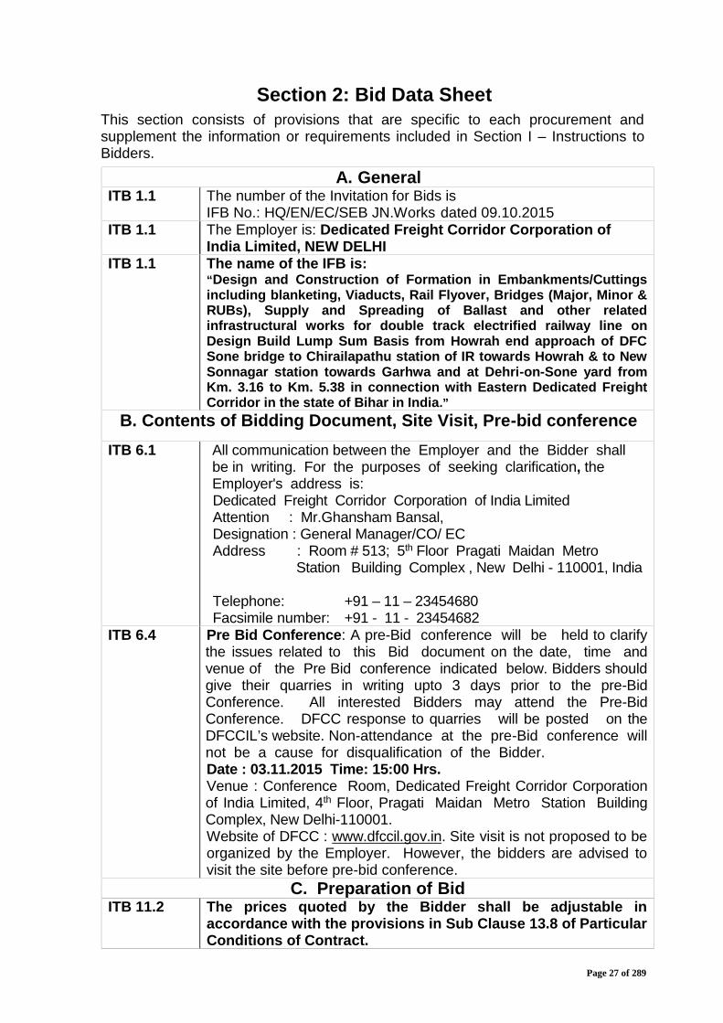
Section 2: Bid Data SheetThis section consists of provisions that are specific to each procurement andsupplement the information or requirements included in Section I – Instructions toBidders.
A. GeneralITB 1.1 The number of the Invitation for Bids is
IFB No.: HQ/EN/EC/SEB JN.Works dated 09.10.2015ITB 1.1 The Employer is: Dedicated Freight Corridor Corporation of
India Limited, NEW DELHIITB 1.1 The name of the IFB is:
“Design and Construction of Formation in Embankments/Cuttingsincluding blanketing, Viaducts, Rail Flyover, Bridges (Major, Minor &RUBs), Supply and Spreading of Ballast and other relatedinfrastructural works for double track electrified railway line onDesign Build Lump Sum Basis from Howrah end approach of DFCSone bridge to Chirailapathu station of IR towards Howrah & to NewSonnagar station towards Garhwa and at Dehri-on-Sone yard fromKm. 3.16 to Km. 5.38 in connection with Eastern Dedicated FreightCorridor in the state of Bihar in India.”
B. Contents of Bidding Document, Site Visit, Pre-bid conferenceITB 6.1 All communication between the Employer and the Bidder shall
be in writing. For the purposes of seeking clarification, theEmployer's address is:Dedicated Freight Corridor Corporation of India LimitedAttention : Mr.Ghansham Bansal,Designation : General Manager/CO/ ECAddress : Room # 513; 5th Floor Pragati Maidan Metro
Station Building Complex , New Delhi - 110001, India
Telephone: +91 – 11 – 23454680Facsimile number: +91 - 11 - 23454682
ITB 6.4 Pre Bid Conference: A pre-Bid conference will be held to clarifythe issues related to this Bid document on the date, time andvenue of the Pre Bid conference indicated below. Bidders shouldgive their quarries in writing upto 3 days prior to the pre-BidConference. All interested Bidders may attend the Pre-BidConference. DFCC response to quarries will be posted on theDFCCIL’s website. Non-attendance at the pre-Bid conference willnot be a cause for disqualification of the Bidder.Date : 03.11.2015 Time: 15:00 Hrs.Venue : Conference Room, Dedicated Freight Corridor Corporationof India Limited, 4th Floor, Pragati Maidan Metro Station BuildingComplex, New Delhi-110001.Website of DFCC : www.dfccil.gov.in. Site visit is not proposed to beorganized by the Employer. However, the bidders are advised tovisit the site before pre-bid conference.
C. Preparation of BidITB 11.2 The prices quoted by the Bidder shall be adjustable in
accordance with the provisions in Sub Clause 13.8 of ParticularConditions of Contract.

Page 28 of 289
ITB 15.1 The bid validity period shall be 180 (One hundred and Eighty)days.
ITB 16.1 The Bidder should submit along with the bid, a bid security for Rs. 3.50crore (Rupees Three Crore Fifty Lakhs only) in the following form :
i) FDR (Fixed deposit receipt) / Demand Draft / Banker’s Cheque / PayOrder for Rs.1.00 Crore
and
ii) Bank Guarantee as per format enclosed as BDF-9A for Rs. 2.50crore.
in favour of “Dedicated Freight Corridor Corporation of India Ltd.,New Delhi”from Nationalised / Indian Scheduled Commercial Bankin original form.
The validity of FDR should not be less than 270 days.
ITB 16.4 The bid security of the successful Bidder submitted in the form ofBank Guarantee shall be returned on Execution of contractAgreement and submission of Performance Guarantee.
However, bid security of the successful Bidder submitted in the formof FDR (Fixed deposit receipt) / Demand Draft / Banker’s Cheque /Pay Order for Rs. 1.00 Crore shall be retained as Retention Moneyand adjusted against the Retention money (reference GCC/PCCsub-clause 14.9).
ITB 17.2 The written confirmation of authorization to sign on behalf of theBidder shall consist of:In case of Companies
Power of Attorney authorizing the signatory of the bidto commit the bidder.
In case of Joint Venture Power of Attorney for Authorised Signatory of Joint
Venture.D. Submission and Opening of Bids :
ITB 19.1 Tender Box for submission of Bid shall remain open:From 10.00 Hrs to 17:00 Hrs on 07.12.2015 & 08.12.2015 andUpto 15:00 hrs. of 09.12.2015 at the address given below:General Manager/CO/ ECRoom # 513; 5th Floor Pragati Maidan Metro Station BuildingComplex, New Delhi - 110001, IndiaTelephone: +91-11- 23454680Facsimile number: +91-11-23454682
ITB 21.1 The Technical bid opening shall take place at:Dedicated Freight Corridor Corporation of India Limited,Conference Hall; 4th Floor, DFCCIL, Pragati Maidan Metro StationBuilding Complex , New Delhi - 110001, IndiaTechnical Bid Opening:Date: 09.12.2015Time: 15:30 hrs.

Page 29 of 289
Section III
Evaluation and QualificationCriteria
Page 30 of 289
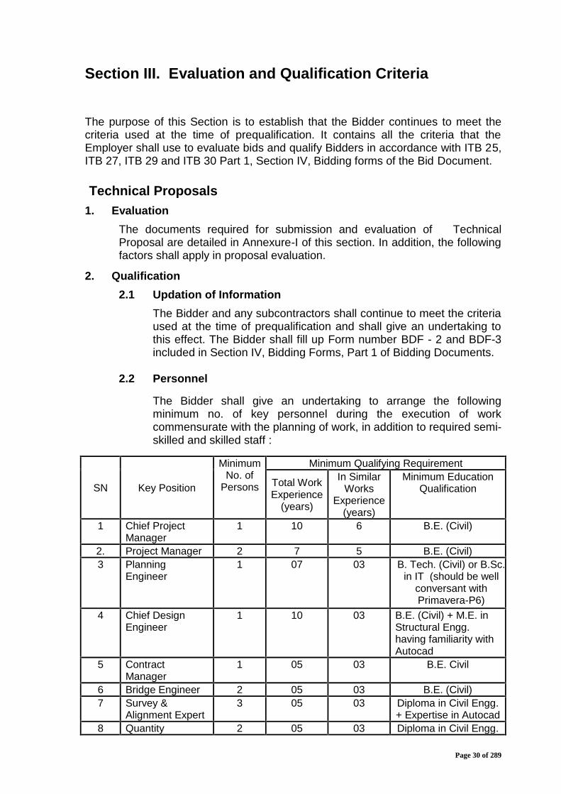
Section III. Evaluation and Qualification Criteria
The purpose of this Section is to establish that the Bidder continues to meet thecriteria used at the time of prequalification. It contains all the criteria that theEmployer shall use to evaluate bids and qualify Bidders in accordance with ITB 25,ITB 27, ITB 29 and ITB 30 Part 1, Section IV, Bidding forms of the Bid Document.
Technical Proposals1. Evaluation
The documents required for submission and evaluation of TechnicalProposal are detailed in Annexure-I of this section. In addition, the followingfactors shall apply in proposal evaluation.
2. Qualification2.1 Updation of Information
The Bidder and any subcontractors shall continue to meet the criteriaused at the time of prequalification and shall give an undertaking tothis effect. The Bidder shall fill up Form number BDF - 2 and BDF-3included in Section IV, Bidding Forms, Part 1 of Bidding Documents.
2.2 Personnel
The Bidder shall give an undertaking to arrange the followingminimum no. of key personnel during the execution of workcommensurate with the planning of work, in addition to required semi-skilled and skilled staff :
SN Key Position
MinimumNo. of
Persons
Minimum Qualifying Requirement
Total WorkExperience
(years)
In SimilarWorks
Experience(years)
Minimum EducationQualification
1 Chief ProjectManager
1 10 6 B.E. (Civil)
2. Project Manager 2 7 5 B.E. (Civil)3 Planning
Engineer1 07 03 B. Tech. (Civil) or B.Sc.
in IT (should be wellconversant withPrimavera-P6)
4 Chief DesignEngineer
1 10 03 B.E. (Civil) + M.E. inStructural Engg.having familiarity withAutocad
5 ContractManager
1 05 03 B.E. Civil
6 Bridge Engineer 2 05 03 B.E. (Civil)7 Survey &
Alignment Expert3 05 03 Diploma in Civil Engg.
+ Expertise in Autocad8 Quantity 2 05 03 Diploma in Civil Engg.
Page 31 of 289
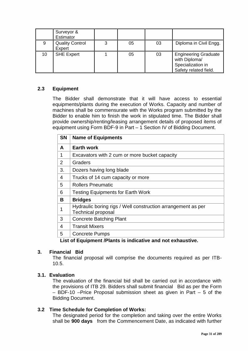
Surveyor &Estimator
9 Quality ControlExpert
3 05 03 Diploma in Civil Engg.
10 SHE Expert 1 05 03 Engineering Graduatewith Diploma/Specialization inSafety related field.
2.3 Equipment
The Bidder shall demonstrate that it will have access to essentialequipments/plants during the execution of Works. Capacity and number ofmachines shall be commensurate with the Works program submitted by theBidder to enable him to finish the work in stipulated time. The Bidder shallprovide ownership/renting/leasing arrangement details of proposed items ofequipment using Form BDF-9 in Part – 1 Section IV of Bidding Document.
List of Equipment /Plants is indicative and not exhaustive.
3. Financial BidThe financial proposal will comprise the documents required as per ITB-10.5.
3.1. EvaluationThe evaluation of the financial bid shall be carried out in accordance withthe provisions of ITB 29. Bidders shall submit financial Bid as per the Form– BDF-10 –Price Proposal submission sheet as given in Part – 5 of theBidding Document.
3.2 Time Schedule for Completion of Works:The designated period for the completion and taking over the entire Worksshall be 900 days from the Commencement Date, as indicated with further
SN Name of Equipments
A Earth work1 Excavators with 2 cum or more bucket capacity2 Graders3. Dozers having long blade4 Trucks of 14 cum capacity or more5 Rollers Pneumatic6 Testing Equipments for Earth WorkB Bridges
1 Hydraulic boring rigs / Well construction arrangement as perTechnical proposal
3 Concrete Batching Plant4 Transit Mixers5 Concrete Pumps

Page 32 of 289
details in Para 8.2 of GCC. Bidders shall confirm that their TechnicalProposals and Financial proposal are based on this Time Schedule forCompletion. No credit of any kind will be given in the evaluation of TechnicalProposals and Financial proposals, to a Proposal and/ or a Bid offering tocomplete the Works earlier than this designated period. However, TechnicalProposals and Financial Bids offering to complete the Works later than thisdesignated period shall be rejected by the Employer.
Page 33 of 289
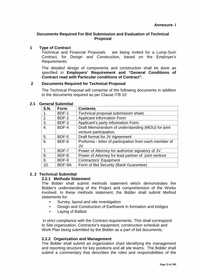
Annexure- I
Documents Required For Bid Submission and Evaluation of TechnicalProposal
1 Type of ContractTechnical and Financial Proposals are being invited for a Lump-SumContract, for Design and Construction, based on the Employer’sRequirements.The detailed design of components and construction shall be done asspecified in Employers’ Requirement and “General Conditions ofContract read with Particular conditions of Contract”.
2 Documents Required for Technical ProposalThe Technical Proposal will comprise of the following documents in additionto the documents required as per Clause ITB 10:
2.1 General SubmittalS.N. Form Contents1. BDF-1 Technical proposal submission sheet.2. BDF-2 Applicant information Form3. BDF-3 Applicant’s party information Form4. BDF-4 Draft Memorandum of understanding (MOU) for joint
venture participation.5. BDF-5 Draft format for JV Agreement6. BDF-6 Proforma - letter of participation from each member of
JV.7. BDF-7 Power of Attorney for authorize signatory of JV.8. BDF-8 Power of Attorney for lead partner of joint venture9. BDF-9 Contractors’ Equipment10. BDF-9A Form of Bid Security (Bank Guarantee)
2. 2 Technical Submittal2.2.1 Methods StatementThe Bidder shall submit methods statement which demonstrates theBidder’s understanding of the Project and comprehension of the Worksinvolved. In these methods statement, the Bidder shall submit Methodstatements for:
Survey, layout and site investigation Design and Construction of Earthwork in formation and bridges Laying of Ballast
in strict compliance with the Contract requirements. This shall correspondto Site organization, Contractor’s equipment, construction schedule andWork Plan being submitted by the Bidder as a part of bid documents.
2.2.2 Organization and ManagementThe Bidder shall submit an organization chart identifying the managementand reporting structure for key positions and all site teams. The Bidder shallsubmit a commentary that describes the roles and responsibilities of the
Page 34 of 289
various key positions in the organization structure, the minimumqualifications, channel of communication, organization they come from andhow this organization structure will manage the execution of the workswithin the scheduled period.
2.2.3 Bid Programme/Work PlanThe Bidder shall submit a bid programme/Work Plan which shall indicatehow the Bidder intends to organize and carry out the Works by breakingthem into various activities and completing those activities by appropriateMilestones so that the whole of the work gets completed within the time ofcompletion as mentioned in GCC para 8.2. The bid programme/Work Planshall be prepared in terms of weeks from the Date of Commencement ofWorks, taking D as the Commencement Date and other time schedulesmarked in D+ format. (Refer to Explanatory Note 1 at the end of thisSection).
2.2.4 Documents for Safety and Quality PlansThe Bidder shall submit the following documents, which shall demonstrateclearly the Bidder’s proposals for achieving effective and efficient Safety andQuality procedures.a) Outline Safety Planb) Outline Quality Planc) Outline Environmental Plan
(Refer to Explanatory Note 2 at the end of this Section)
2.2.5 Performance Parameters ComplianceThe Bidder shall submit details of compliance with the Employers’Requirements as listed in Part 2 of bidding document.

Page 35 of 289
Explanatory Note No. 1
Reference Paragraph 2.2.3 Bid Programme/Work Plan of Annexure- I
Requirements of Bid Programme/Work Plan
(1) The Bidder shall submit a Bid Programme/Work Plan which shall indicatehow the Bidder intends to organize and carry out the Works by breakingthem into various activities and completing those activities by appropriateMilestones so that the whole of the work gets completed within the time ofcompletion as mentioned in GCC para 8.2. The bid programme shall beprepared in terms of weeks from the Date of Commencement of Works,taking D as the Commencement Date and other time schedules marked inD+ format. This may be in form of an Excel spread sheet/primavera orsimilar programme output.
(2) The Bid Programme/Work Plan shall follow the instructions given in Part 2,Section V, “Employer’s Requirements/ Volume 6 Appendix 4,PROJECT PROGRAM REQUIREMENTS”
(3) The Bid Programme/Work Plan shall take into account the Bidder’sproposed Design Submission Programme and should:(a) take due account of the design co-ordination interface periods during
which the Contractor shall be required to undertake and complete allaspects of design co-ordination with other consultants engaged in thereview of the design of the Project such design will be compatible andcoordinated with others and allowing adequate time for theEmployer’s assessments and decisions.
(b) be consistent with the overall Work Plan and in accordance with theEmployer's Requirements;
(c) make adequate allowance for periods of time for review by authoritieswhose approval is necessary
(d) include a schedule identifying, describing, cross-referencing andexplaining the Design packages and submissions which the Bidderintends to submit.
(4) The Bid Programme/Work Plan shall contain sufficient detail to assure theEmployer of the feasibility of the plan and approach proposed by the Bidder.
(5) The Bid Programme/Work Plan shall be accompanied by a narrativestatement that shall describe Programme activities, assumptions and logic,and highlight the Bidder's perception of the construction and completion ofthe work. This narrative statement shall also indicate which elements of theWorks the Bidder intends to carry out off-Site with details of the proposedlocations of where any such work is to be carried out, the facilities available.In particular the Bidder must state the assumptions made in respect of theinterfaces with the Employer, other contractors and any requirements forinformation on matters which would affect his works.
(6) All programmes/plans shall include design, procurement periods, majormaterial, on site, offsite, temporary construction, interface and periods for

Page 36 of 289
System wide, utility and adjacent contractors, and testing alongwith otherrelevant information.
(7) The proposed submission of the Bid Programme/ Work Plan and DesignSubmission Programme shall not, in any event, be construed as asubmission under Clause 8.3 (Programme) of the General Conditions ofContract.
Page 37 of 289
Explanatory Note No. 2
Reference Paragraph 2.2.4 - Documents for Safety, Quality andEnvironmental plans of Annexure-I
OUTLINE SAFETY PLAN
The Bidder shall submit as part of his bid an Outline Safety Plan which shallcontain sufficient information to demonstrate clearly the Bidder’s proposals forachieving effective and efficient safety procedures. The Outline Safety Plan shouldinclude an outline of the safety procedures and regulations to be developed andthe mechanism by which they will be implemented for ensuring safety as requiredunder the Employer's Requirements and Sub Clause 4.8 and 6.7 of the GCC.
The Outline Safety Plan shall be headed with a formal statement of policy inrelation to safety and shall be sufficiently informative to define the Bidder's safetyplans and set out in summary an adequate basis for the development of the SiteSafety Plan to be submitted in accordance with Sub Clause 4.8 and 6.7 of the GCCincluding a testing and strategy/plan for the whole of the Works.
OUTLINE QUALITY PLAN
The Bidder shall submit as part of his bid an Outline Quality Plan which shallcontain sufficient information to demonstrate clearly the Bidder’s proposals forachieving effective and efficient Quality Assurance and Control System. The Planshould include an outline of the procedures and regulations to be developed andthe mechanism by which they will be implemented for ensuring Quality as requiredin terms of the Employer’s Requirements. It shall also include an outline ofprocedures, verification and validation for all tests and materials for all the Worksbeing done by him under this Contract.
OUTLINE ENVIRONMENTAL PLAN
The Bidder shall submit as part an Outline Environmental Plan illustrating theintended means of compliance with the requirements of Appendix 12, Part-2 of thebid document and shall set out in summary form an adequate basis for thedevelopment of the more detailed document to be submitted under Sub Clause4.18 of GCC. The outlined Environmental Plan shall contain sufficient informationto demonstrate clearly the proposed method of achieving the Bidder’senvironmental objectives with regard to the requirement of the contract.
The outline environmental Plan shall be headed with a formal statement of Policyin relation to environmental protection and shall be sufficiently informative to definethe Bidder’s environmental plans and set out in summary an adequate basis for thesubmission of a detailed and comprehensive site environmental qualitymanagement plan to be submitted in accordance with sub clause 4.18 of GCC.The outline plan shall include the methods and procedures for the EnvironmentalImpact Assessment to be performed under the contract.

Page 38 of 289
Section IV
Bidding Forms
Page 39 of 289
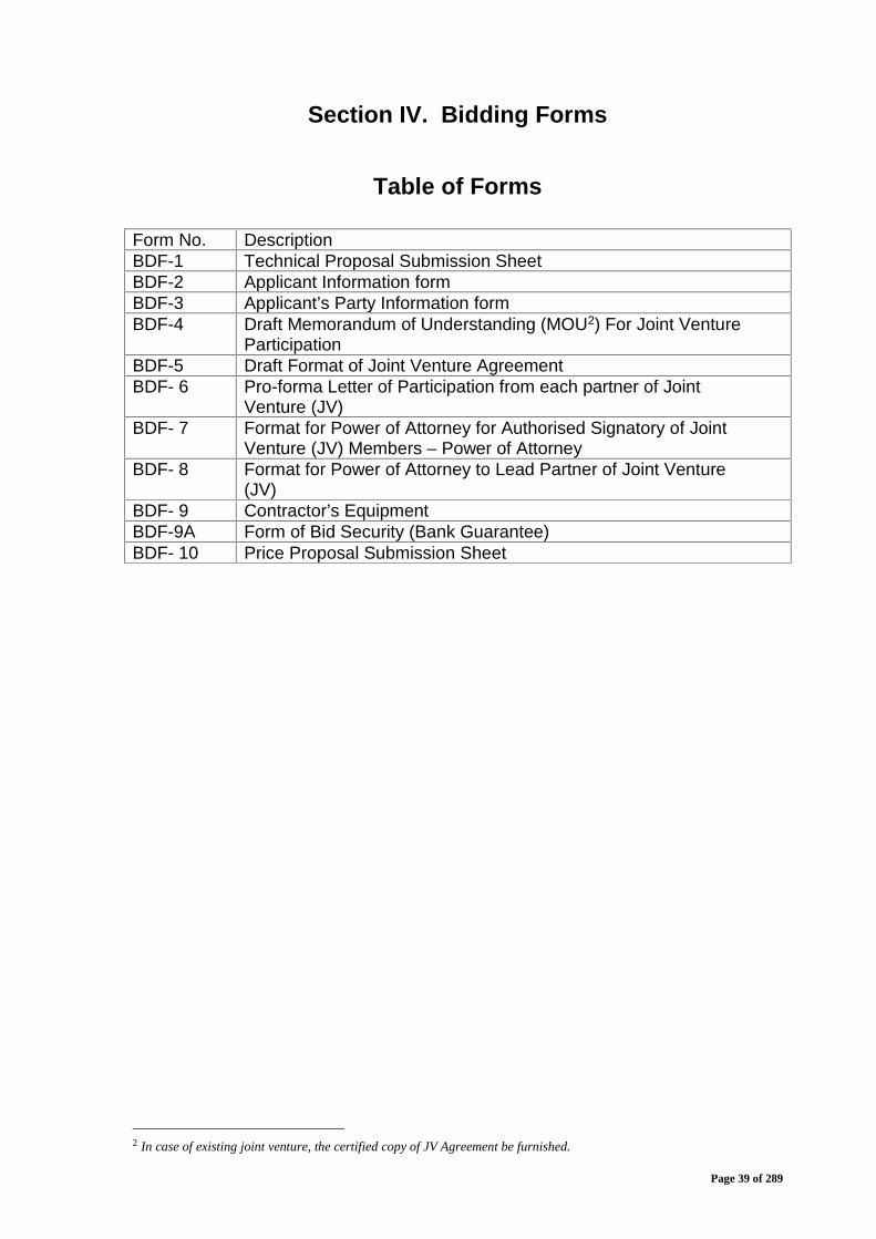
Section IV. Bidding Forms
Table of Forms
Form No. DescriptionBDF-1 Technical Proposal Submission SheetBDF-2 Applicant Information formBDF-3 Applicant’s Party Information formBDF-4 Draft Memorandum of Understanding (MOU2) For Joint Venture
ParticipationBDF-5 Draft Format of Joint Venture AgreementBDF- 6 Pro-forma Letter of Participation from each partner of Joint
Venture (JV)BDF- 7 Format for Power of Attorney for Authorised Signatory of Joint
Venture (JV) Members – Power of AttorneyBDF- 8 Format for Power of Attorney to Lead Partner of Joint Venture
(JV)BDF- 9 Contractor’s EquipmentBDF-9A Form of Bid Security (Bank Guarantee)BDF- 10 Price Proposal Submission Sheet
2 In case of existing joint venture, the certified copy of JV Agreement be furnished.
Page 40 of 289
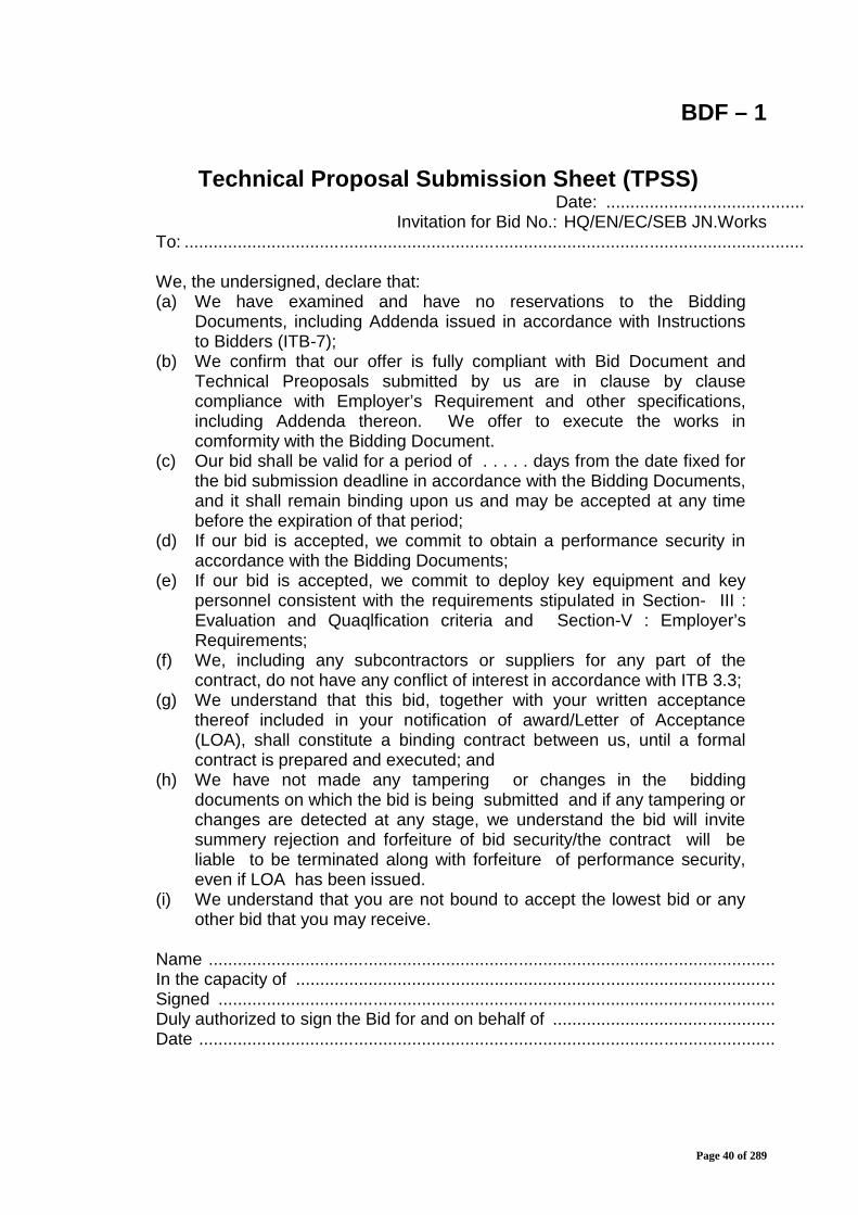
BDF – 1
Technical Proposal Submission Sheet (TPSS)Date: .........................................
Invitation for Bid No.: HQ/EN/EC/SEB JN.WorksTo: ................................................................................................................................
We, the undersigned, declare that:(a) We have examined and have no reservations to the Bidding
Documents, including Addenda issued in accordance with Instructionsto Bidders (ITB-7);
(b) We confirm that our offer is fully compliant with Bid Document andTechnical Preoposals submitted by us are in clause by clausecompliance with Employer’s Requirement and other specifications,including Addenda thereon. We offer to execute the works incomformity with the Bidding Document.
(c) Our bid shall be valid for a period of . . . . . days from the date fixed forthe bid submission deadline in accordance with the Bidding Documents,and it shall remain binding upon us and may be accepted at any timebefore the expiration of that period;
(d) If our bid is accepted, we commit to obtain a performance security inaccordance with the Bidding Documents;
(e) If our bid is accepted, we commit to deploy key equipment and keypersonnel consistent with the requirements stipulated in Section- III :Evaluation and Quaqlfication criteria and Section-V : Employer’sRequirements;
(f) We, including any subcontractors or suppliers for any part of thecontract, do not have any conflict of interest in accordance with ITB 3.3;
(g) We understand that this bid, together with your written acceptancethereof included in your notification of award/Letter of Acceptance(LOA), shall constitute a binding contract between us, until a formalcontract is prepared and executed; and
(h) We have not made any tampering or changes in the biddingdocuments on which the bid is being submitted and if any tampering orchanges are detected at any stage, we understand the bid will invitesummery rejection and forfeiture of bid security/the contract will beliable to be terminated along with forfeiture of performance security,even if LOA has been issued.
(i) We understand that you are not bound to accept the lowest bid or anyother bid that you may receive.
Name .....................................................................................................................In the capacity of ...................................................................................................Signed ...................................................................................................................Duly authorized to sign the Bid for and on behalf of ..............................................Date .......................................................................................................................
Page 41 of 289
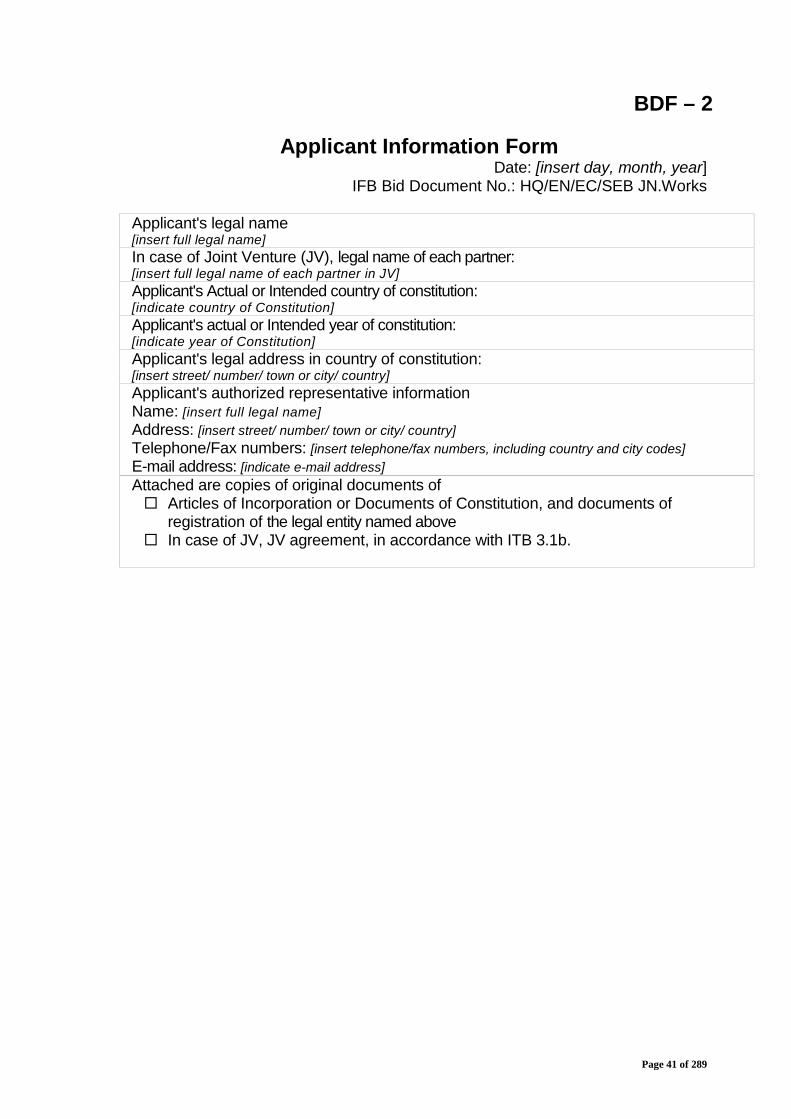
BDF – 2
Applicant Information FormDate: [insert day, month, year]
IFB Bid Document No.: HQ/EN/EC/SEB JN.Works
Applicant's legal name[insert full legal name]In case of Joint Venture (JV), legal name of each partner:[insert full legal name of each partner in JV]Applicant's Actual or Intended country of constitution:[indicate country of Constitution]Applicant's actual or Intended year of constitution:[indicate year of Constitution]Applicant's legal address in country of constitution:[insert street/ number/ town or city/ country]Applicant's authorized representative informationName: [insert full legal name]Address: [insert street/ number/ town or city/ country]Telephone/Fax numbers: [insert telephone/fax numbers, including country and city codes]E-mail address: [indicate e-mail address]Attached are copies of original documents of Articles of Incorporation or Documents of Constitution, and documents of
registration of the legal entity named above In case of JV, JV agreement, in accordance with ITB 3.1b.

Page 42 of 289
BDF – 3
Applicant's Party Information Form[The following form shall be filled in for the Applicant's parties includingpartner(s) of a joint venture]
Date: [insert day, month, year]IFB Bid Document No.: HQ/EN/EC/SEB JN.Works
JV applicant legal name:[insert full legal name]Applicant's Party legal name:[insert full legal name of Applicant's Party]Applicant's Party country of registration:[indicate country of registration]Applicant Party's year of constitution:[indicate year of constitution]Applicant Party's legal address in country of constitution:[insert street/ number/ town or city/ country]Applicant Party's authorized representative informationName: [insert full legal name]Address: [insert street/ number/ town or city/ country]Telephone/Fax numbers: [insert telephone/fax numbers, including country and city codes]E-mail address: [indicate e-mail address]Attached are copies of original documents of Articles of Incorporation or Documents of Constitution, and RegistrationDocuments of the legal entity named above, in accordance with ITB 3.1 (b).
Note :Separate BDF form is required for all individual participants (members) in the JV.
Page 43 of 289
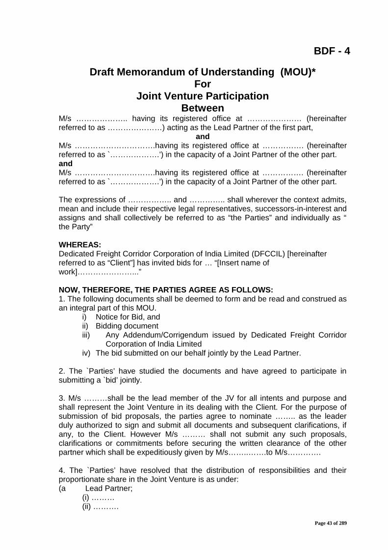
BDF - 4
Draft Memorandum of Understanding (MOU)*For
Joint Venture ParticipationBetween
M/s ……………….. having its registered office at ………………… (hereinafterreferred to as …………………) acting as the Lead Partner of the first part,
andM/s ………………………….having its registered office at ……………. (hereinafterreferred to as `……………….’) in the capacity of a Joint Partner of the other part.andM/s ………………………….having its registered office at ……………. (hereinafterreferred to as `……………….’) in the capacity of a Joint Partner of the other part.
The expressions of …………….. and ………….. shall wherever the context admits,mean and include their respective legal representatives, successors-in-interest andassigns and shall collectively be referred to as “the Parties” and individually as “the Party”
WHEREAS:Dedicated Freight Corridor Corporation of India Limited (DFCCIL) [hereinafterreferred to as “Client”] has invited bids for … “[Insert name ofwork]…………………...”
NOW, THEREFORE, THE PARTIES AGREE AS FOLLOWS:1. The following documents shall be deemed to form and be read and construed asan integral part of this MOU.
i) Notice for Bid, andii) Bidding documentiii) Any Addendum/Corrigendum issued by Dedicated Freight Corridor
Corporation of India Limitediv) The bid submitted on our behalf jointly by the Lead Partner.
2. The `Parties’ have studied the documents and have agreed to participate insubmitting a `bid’ jointly.
3. M/s ………shall be the lead member of the JV for all intents and purpose andshall represent the Joint Venture in its dealing with the Client. For the purpose ofsubmission of bid proposals, the parties agree to nominate …….. as the leaderduly authorized to sign and submit all documents and subsequent clarifications, ifany, to the Client. However M/s ……… shall not submit any such proposals,clarifications or commitments before securing the written clearance of the otherpartner which shall be expeditiously given by M/s……..…….to M/s………….
4. The `Parties’ have resolved that the distribution of responsibilities and theirproportionate share in the Joint Venture is as under:(a Lead Partner;
(i) ………(ii) ……….
Page 44 of 289
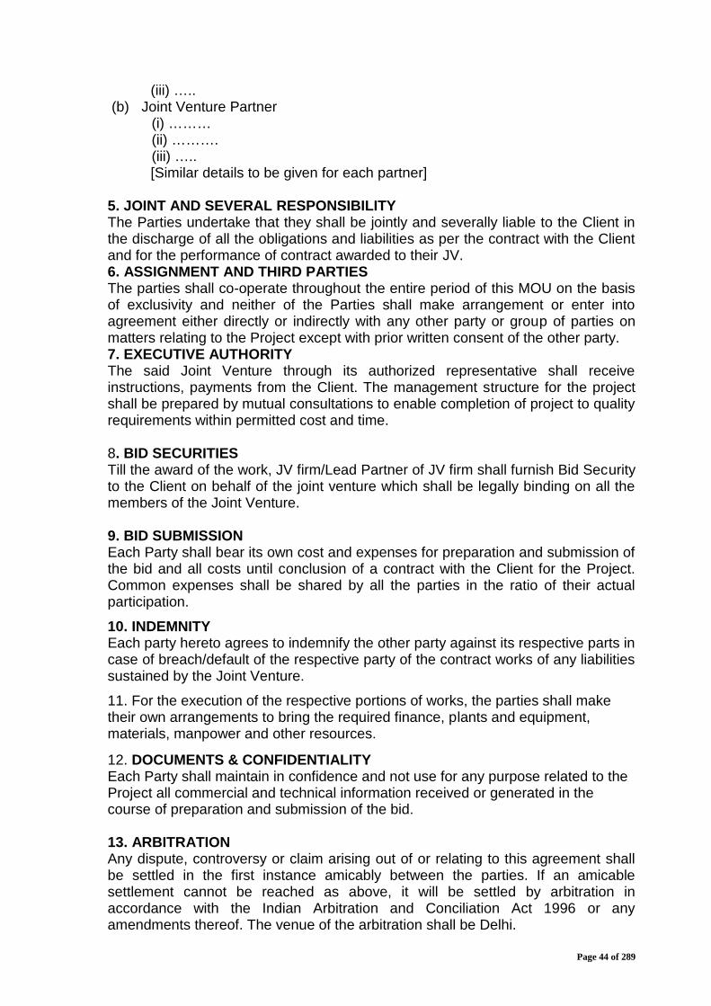
(iii) …..(b) Joint Venture Partner
(i) ………(ii) ……….(iii) …..[Similar details to be given for each partner]
5. JOINT AND SEVERAL RESPONSIBILITYThe Parties undertake that they shall be jointly and severally liable to the Client inthe discharge of all the obligations and liabilities as per the contract with the Clientand for the performance of contract awarded to their JV.6. ASSIGNMENT AND THIRD PARTIESThe parties shall co-operate throughout the entire period of this MOU on the basisof exclusivity and neither of the Parties shall make arrangement or enter intoagreement either directly or indirectly with any other party or group of parties onmatters relating to the Project except with prior written consent of the other party.7. EXECUTIVE AUTHORITYThe said Joint Venture through its authorized representative shall receiveinstructions, payments from the Client. The management structure for the projectshall be prepared by mutual consultations to enable completion of project to qualityrequirements within permitted cost and time.
8. BID SECURITIESTill the award of the work, JV firm/Lead Partner of JV firm shall furnish Bid Securityto the Client on behalf of the joint venture which shall be legally binding on all themembers of the Joint Venture.
9. BID SUBMISSIONEach Party shall bear its own cost and expenses for preparation and submission ofthe bid and all costs until conclusion of a contract with the Client for the Project.Common expenses shall be shared by all the parties in the ratio of their actualparticipation.
10. INDEMNITYEach party hereto agrees to indemnify the other party against its respective parts incase of breach/default of the respective party of the contract works of any liabilitiessustained by the Joint Venture.
11. For the execution of the respective portions of works, the parties shall maketheir own arrangements to bring the required finance, plants and equipment,materials, manpower and other resources.
12. DOCUMENTS & CONFIDENTIALITYEach Party shall maintain in confidence and not use for any purpose related to theProject all commercial and technical information received or generated in thecourse of preparation and submission of the bid.
13. ARBITRATIONAny dispute, controversy or claim arising out of or relating to this agreement shallbe settled in the first instance amicably between the parties. If an amicablesettlement cannot be reached as above, it will be settled by arbitration inaccordance with the Indian Arbitration and Conciliation Act 1996 or anyamendments thereof. The venue of the arbitration shall be Delhi.
Page 45 of 289
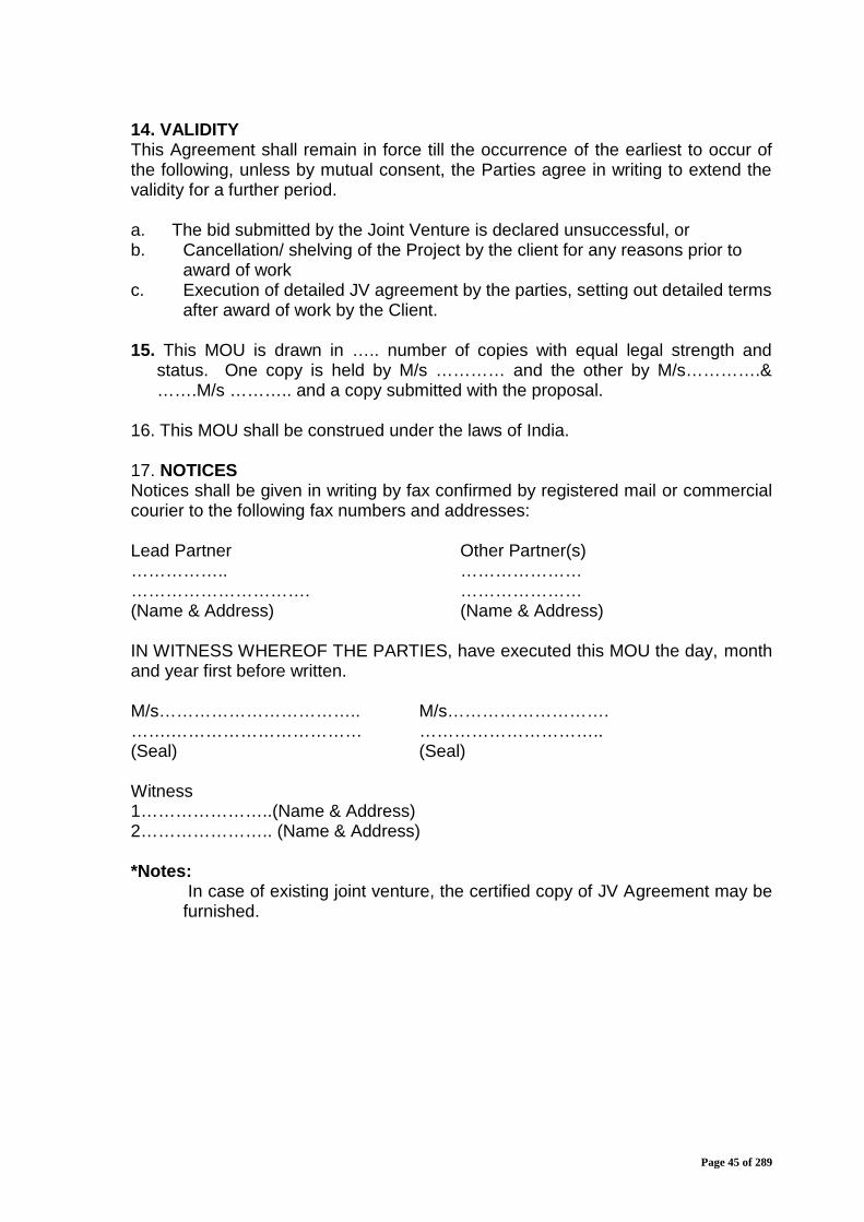
14. VALIDITYThis Agreement shall remain in force till the occurrence of the earliest to occur ofthe following, unless by mutual consent, the Parties agree in writing to extend thevalidity for a further period.
a. The bid submitted by the Joint Venture is declared unsuccessful, orb. Cancellation/ shelving of the Project by the client for any reasons prior to
award of workc. Execution of detailed JV agreement by the parties, setting out detailed terms
after award of work by the Client.
15. This MOU is drawn in ….. number of copies with equal legal strength andstatus. One copy is held by M/s ………… and the other by M/s………….&…….M/s ……….. and a copy submitted with the proposal.
16. This MOU shall be construed under the laws of India.
17. NOTICESNotices shall be given in writing by fax confirmed by registered mail or commercialcourier to the following fax numbers and addresses:
Lead Partner Other Partner(s)…………….. ……………………………………………. …………………(Name & Address) (Name & Address)
IN WITNESS WHEREOF THE PARTIES, have executed this MOU the day, monthand year first before written.
M/s…………………………….. M/s……………………….…….…………………………… …………………………..(Seal) (Seal)
Witness1…………………..(Name & Address)2………………….. (Name & Address)
*Notes:In case of existing joint venture, the certified copy of JV Agreement may be
furnished.
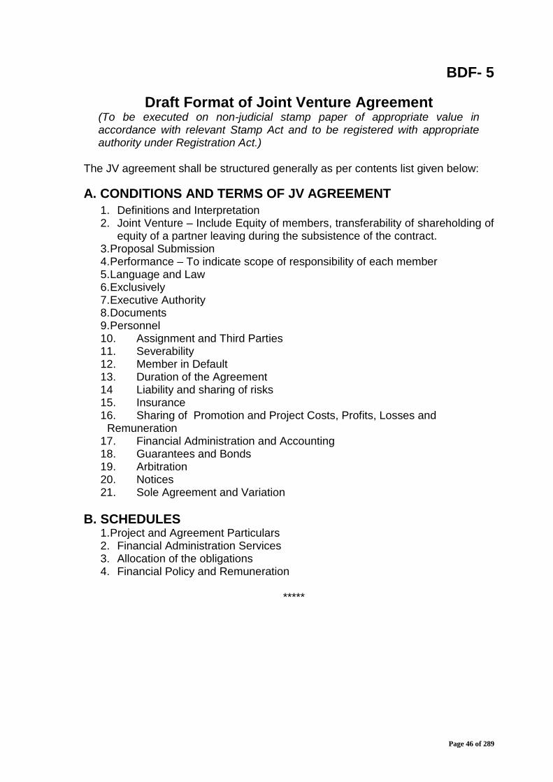
Page 46 of 289
BDF- 5
Draft Format of Joint Venture Agreement(To be executed on non-judicial stamp paper of appropriate value inaccordance with relevant Stamp Act and to be registered with appropriateauthority under Registration Act.)
The JV agreement shall be structured generally as per contents list given below:
A. CONDITIONS AND TERMS OF JV AGREEMENT1. Definitions and Interpretation2. Joint Venture – Include Equity of members, transferability of shareholding of
equity of a partner leaving during the subsistence of the contract.3.Proposal Submission4.Performance – To indicate scope of responsibility of each member5.Language and Law6.Exclusively7.Executive Authority8.Documents9.Personnel10. Assignment and Third Parties11. Severability12. Member in Default13. Duration of the Agreement14 Liability and sharing of risks15. Insurance16. Sharing of Promotion and Project Costs, Profits, Losses and
Remuneration17. Financial Administration and Accounting18. Guarantees and Bonds19. Arbitration20. Notices21. Sole Agreement and Variation
B. SCHEDULES1.Project and Agreement Particulars2. Financial Administration Services3. Allocation of the obligations4. Financial Policy and Remuneration
*****

Page 47 of 289
BDF- 6
Pro-forma Letter of Participation From Each Partner ofJoint Venture (JV)
(To be executed on non-judicial stamp paper of appropriate value in accordancewith relevant Stamp Act and to be registered with appropriate authority underRegistration Act.)
No…. Dated
From:……………………..………………..
To,The Managing Director,Dedicated Freight Corridor Corporation of India Limited5th Floor, Pragati Maidan Metro Stn. Building Complex.,New Delhi 110001.
Gentlemen,
Re: …“[Insert name of work]…………………………………………..”.
Ref: Your notice for Invitation for Bid (IFB) No. HQ/EN/EC/SEB JN.Works dated…………..
1. We wish to confirm that our company/firm has formed a Joint Venturewith(i)……………. & ii)……………….. for the purposes associated with IFBreferred to above.
(Members who are not the lead partner of the JV should add the followingparagraph)*.
2. ‘The JV is led by … whom we hereby authorise to act on our behalf for thepurposes of submission of Bid for ………. and authorise to incur liabilitiesand receive instructions for and on behalf of any and all the partners orconstituents of the Joint Venture.’
OR
(Member(s) being the lead member of the group should add the followingparagraph)*
2. ‘In this group we act as leader and, for the purposes of applying for Bid,represent the Joint Venture:

Page 48 of 289
3. In the event of our JV being awarded the contract, we agree to be jointly withi) & ii) ……… (names of other members of our JV) and severally liable to theDedicated Freight Corridor Corporation of India Limited, its successors and assignsfor all obligations, duties and responsibilities arising from or imposed by thecontract subsequently entered into between Dedicated Freight CorridorCorporation of India Limited and our JV.
4. *I/We, further agree that entire execution of the contract shall be carried outexclusively through the lead partner.
Yours faithfully,
(Signature)
(Name of Signatory)………………….(Capacity of Signatory)…………………Company Seal * Delete as applicable
Note : In case of existing joint venture, the certified copy of JV Agreement may befurnished.
****
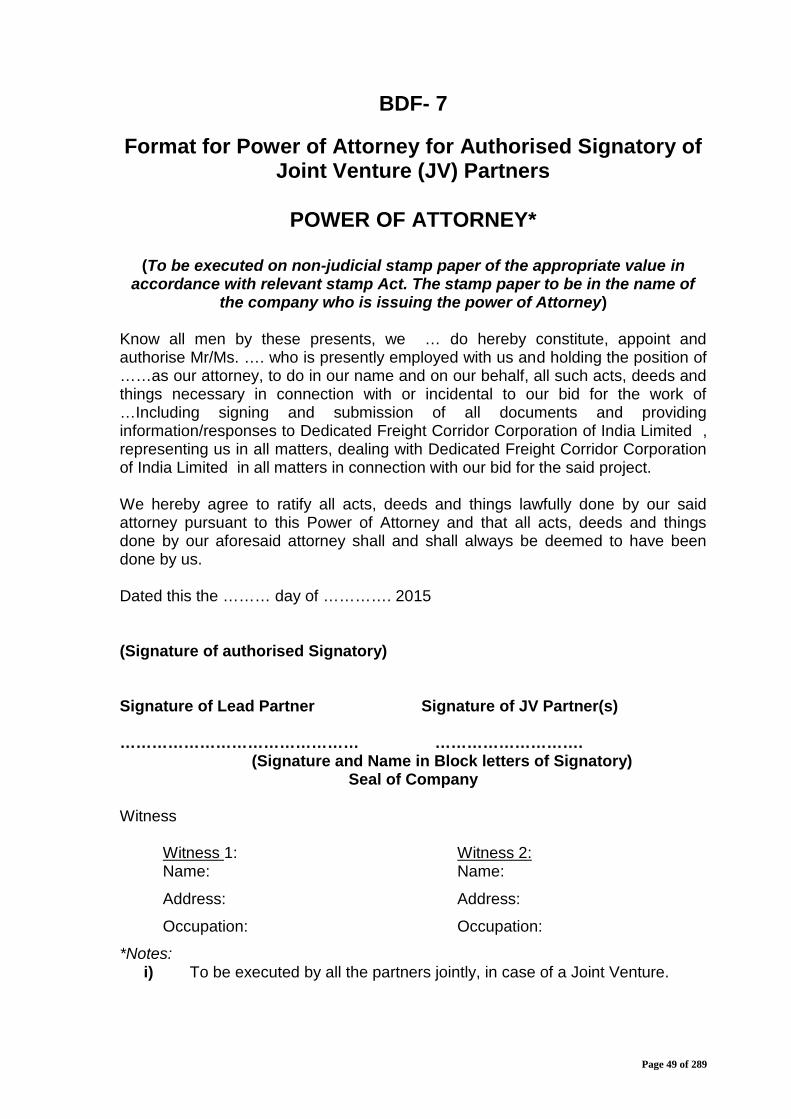
Page 49 of 289
BDF- 7
Format for Power of Attorney for Authorised Signatory ofJoint Venture (JV) Partners
POWER OF ATTORNEY*
(To be executed on non-judicial stamp paper of the appropriate value inaccordance with relevant stamp Act. The stamp paper to be in the name of
the company who is issuing the power of Attorney)
Know all men by these presents, we … do hereby constitute, appoint andauthorise Mr/Ms. …. who is presently employed with us and holding the position of……as our attorney, to do in our name and on our behalf, all such acts, deeds andthings necessary in connection with or incidental to our bid for the work of…Including signing and submission of all documents and providinginformation/responses to Dedicated Freight Corridor Corporation of India Limited ,representing us in all matters, dealing with Dedicated Freight Corridor Corporationof India Limited in all matters in connection with our bid for the said project.
We hereby agree to ratify all acts, deeds and things lawfully done by our saidattorney pursuant to this Power of Attorney and that all acts, deeds and thingsdone by our aforesaid attorney shall and shall always be deemed to have beendone by us.
Dated this the ……… day of …………. 2015
(Signature of authorised Signatory)
Signature of Lead Partner Signature of JV Partner(s)
……………………………………… ……………………….(Signature and Name in Block letters of Signatory)
Seal of Company
Witness
Witness 1:Name:
Address:
Occupation:
Witness 2:Name:
Address:
Occupation:
*Notes:i) To be executed by all the partners jointly, in case of a Joint Venture.

Page 50 of 289
BDF- 8
Format for Power of Attorney to Lead Partner of JointVenture (JV)
(To be executed on non-judicial stamp paper of the appropriate value inaccordance with relevant stamp Act. The stamp paper to be in the name of
the company who is issuing the power of Attorney)
POWER OF ATTORNEY *
Whereas Dedicated Freight Corridor Corporation of India Limited has invited Bidsfor the work of Design and Construction of Formation in Embankments/Cuttingsincluding blanketing, Viaducts, Rail Flyover, Bridges (Major, Minor & RUBs), Supplyand Spreading of Ballast and other related infrastructural works for double trackelectrified railway line on Design Build Lump Sum Basis from Howrah end approachof DFC Sone bridge to Chirailapathu station of IR towards Howrah & to NewSonnagar station towards Garhwa and at Dehri-on-Sone yard from Km. 3.16 to Km.5.38 in connection with Eastern Dedicated Freight Corridor in the state of Bihar inIndia.
Whereas, the members of the Joint Venture comprising of M/s. …, M/s. …, M/s.……, and M/s. …. are interested in submission of bid for the work of …[Insertname of work]… in accordance with the terms and conditions contained in thebidding documents.
Whereas, it is necessary for the members of the Joint Venture to designate one ofthem as the Lead Partner, with all necessary power and authority to do, for and onbehalf of the Joint Venture, all acts, deeds and things as may be necessary inconnection with the Joint Venture's bid for the project, as may be necessary inconnection the Joint Venture's bid for the project.
NOW THIS POWER OF ATTORNEY WITNESSETH THAT:
We, M/s. ………………, hereby designate M/s. ………………………………, beingone of the partners of the Joint Venture, as the lead partner of the Joint Venture, todo on behalf of the Joint Venture, all or any of the acts, deeds or things necessaryor incidental to the Joint Venture's bid for the contract, including submission of bid,participating in conferences, responding to queries, submission of information/documents and generally to represent the Joint Venture in all its dealings with theDFCCIL or any other Government Agency or any person, in connection with theBid/contract for the said work until culmination of the process of bidding till thecontract agreement if successful, is entered into with the Dedicated FreightCorridor Corporation of India Limited and thereafter till the expiry of the contractagreement.
We hereby agree to ratify all acts, deeds and things lawfully done by lead member,our said attorney, pursuant to this power of attorney and that all acts deeds andthings done by our aforesaid attorney shall and shall always be deemed to have
Page 51 of 289
been done by us/ Joint Venture.
Dated this the ………… Day of ……….. 2015
…………………….(Signature)………………………………………(Name in Block letters of Executants)Seal of Company
Witness 1:Name:Address:Occupation:
Witness 2:Name:Address:Occupation:
* To be executed by all the members of the JV except the lead member.The mode of execution of the Power of Attorney should be in accordance with theprocedure, if any, laid down by the applicable law and the charter documents of theexecutant(s) and when it is so required the same should be under common sealaffixed in accordance with the required procedure.
*****

Page 52 of 289
BDF- 9
Contractor’s Equipment
The Bidder shall provide adequate information to demonstrate clearly that it has thecapability to meet the requirements for the key Contractor’s equipment listed inSection III, Evaluation and Qualification Criteria.A separate Form shall be prepared for each item of equipment listed, or foralternative equipment proposed by the Bidder.
Item of equipment
Equipmentinformation
Name of manufacturer
Capacity
Currentstatus
Current location
Details of current commitments
Source Indicate source of the equipment Owned Rented Leased Specially manufactured
Omit the following information for equipment owned by the Bidder.
Owner Name of ownerAddress of owner
Telephone Contact name and titleFax Telex
Agreements Details of rental / lease / manufacture agreements/Consent letterspecific to the project
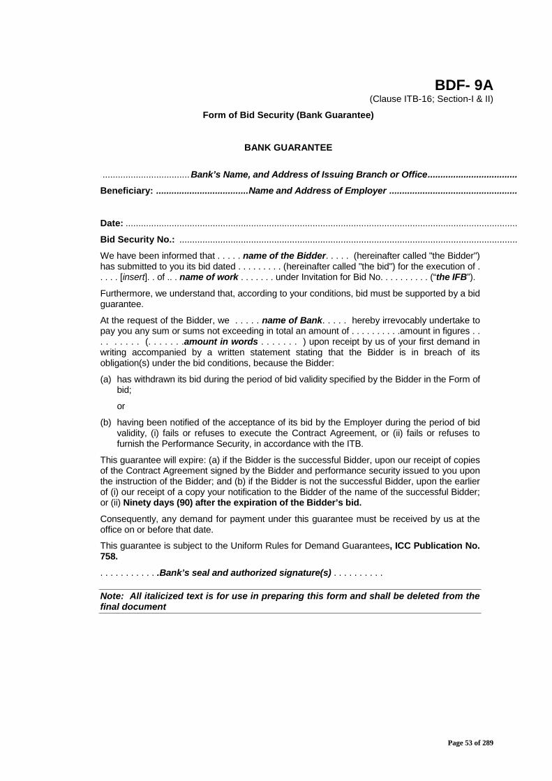
Page 53 of 289
BDF- 9A(Clause ITB-16; Section-I & II)
Form of Bid Security (Bank Guarantee)
BANK GUARANTEE
..................................Bank’s Name, and Address of Issuing Branch or Office...................................
Beneficiary: ....................................Name and Address of Employer ..................................................
Date: .........................................................................................................................................................
Bid Security No.: ....................................................................................................................................
We have been informed that . . . . . name of the Bidder. . . . . (hereinafter called "the Bidder")has submitted to you its bid dated . . . . . . . . . (hereinafter called "the bid") for the execution of .. . . . [insert]. . of .. . name of work . . . . . . . under Invitation for Bid No. . . . . . . . . . (“the IFB”).
Furthermore, we understand that, according to your conditions, bid must be supported by a bidguarantee.
At the request of the Bidder, we . . . . . name of Bank. . . . . hereby irrevocably undertake topay you any sum or sums not exceeding in total an amount of . . . . . . . . . .amount in figures . .. . . . . . . (. . . . . . .amount in words . . . . . . . ) upon receipt by us of your first demand inwriting accompanied by a written statement stating that the Bidder is in breach of itsobligation(s) under the bid conditions, because the Bidder:
(a) has withdrawn its bid during the period of bid validity specified by the Bidder in the Form ofbid;
or
(b) having been notified of the acceptance of its bid by the Employer during the period of bidvalidity, (i) fails or refuses to execute the Contract Agreement, or (ii) fails or refuses tofurnish the Performance Security, in accordance with the ITB.
This guarantee will expire: (a) if the Bidder is the successful Bidder, upon our receipt of copiesof the Contract Agreement signed by the Bidder and performance security issued to you uponthe instruction of the Bidder; and (b) if the Bidder is not the successful Bidder, upon the earlierof (i) our receipt of a copy your notification to the Bidder of the name of the successful Bidder;or (ii) Ninety days (90) after the expiration of the Bidder’s bid.Consequently, any demand for payment under this guarantee must be received by us at theoffice on or before that date.
This guarantee is subject to the Uniform Rules for Demand Guarantees, ICC Publication No.758.. . . . . . . . . . . .Bank’s seal and authorized signature(s) . . . . . . . . . .
Note: All italicized text is for use in preparing this form and shall be deleted from thefinal document

Page 54 of 289
BDF- 10
Price Proposal Submission Sheet
...............................................................................................................................
Please refer Part-5 (Price Schedule) for this form

Page 55 of 289
PART 2
Employer’s Requirement

Page 56 of 289
Section V. Employer’s Requirement
Contents
Volume 1: Scope of WorksVolume 2: GeneralVolume 3: Design Procedures and ProcessesVolume 4: Design Criteria and SpecificationsVolume 5: Construction and TestingVolume 6: Appendices
Appendix 1 UtilitiesAppendix 2 Works Areas and Contract StagesAppendix 3 Design and Construction InterfacesAppendix 4 Project Programme RequirementsAppendix 5 Monthly Progress ReportsAppendix 6 Quality AssuranceAppendix 7 Drawing and CAD StandardsAppendix 8 Works Areas and Temporary Power SupplyAppendix 9 Project CalendarAppendix 10 First Aid BaseAppendix 11 Design CertificateAppendix 12 Site Safety Plan and Environmental Protection
RequirementsAppendix 13 Traffic Block (Possession) Management
Appendix 14 Design StandardsAppendix 15 Engineer’s Accommodation
Page 57 of 289
Section V. Employer’s Requirement
Volume 1 – Scope of Works
CONTENTS
1.0 GENERAL2.0 SCOPE OF WORKS

Page 58 of 289
1. General
1.1 Dedicated Freight Corridor Corporation of India (DFCCIL) is a SpecialPurpose Vehicle set up under the administrative control of Ministry ofRailways to undertake planning & development, mobilization of financialresources and construction, maintenance and operation of the DedicatedFreight Corridors. In the first phase, DFCCIL will be constructing twocorridors – the Western DFC and Eastern DFC- spanning a total length ofabout 3300 route km. The Eastern Corridor, starting from Ludhiana inPunjab and pass through the states of Haryana, Uttar Pradesh, Bihar,Jharkhand and terminate at Dankuni in West Bengal. The Western Corridorwill traverse the distance from Dadri to Mumbai, passing through the statesof UP, Delhi, Haryana, Rajasthan, Gujarat and Maharashtra.
The route alignment of Freight Corridors is mostly parallel to existingadjacent Indian Railway Track. However alignment is on detour at somelocations to avoid social/environmental/wild life impact.
The project entails construction of mostly double-track electrified railwaylines. Bridges and embankment would be fit for 32.5 Tonne Axle load andTrack structure would be designed for handling 25 Tonne axle load withtrain speed up to 100 Kmph.
The Eastern Corridor will handle single stack containers whereas WesternCorridor is planned to cater to double stack containers. Up gradation oftransportation technology, increase in productivity and reduction in unittransportation costs have been taken as guiding principles for freightcorridor.
1.2 Project Information :
DFCCIL work for the section of Mughalsarai (Approx. Rly Km 669) to SoneBridge near Sonnagar (Approx. Rly Km. 550.2) (except from DFC Km. 3.16to Km. 5.38 near Dehri-on-Sone) is under progress.
However, work from Sone Bridge to connection with IR at Chirailapathu (RlyKm.543 towards Howrah), Sone Bridge to connection with IR at NewSonnagar (near Bagahabishunpur towards Garhwa) and from DFC Km. 3.16to Km. 5.38 (near Dehri-on-Sone) has not yet been contracted for execution.
In order to commission the entire section of Mughalsarai to Sonnagar with IRconnections, DFCCIL intends to carry out the works in remaining sections i.e.
“Design and Construction of Formation in Embankments/Cuttings includingblanketing, Viaducts, Rail Flyover, Bridges (Major, Minor & RUBs), Supplyand Spreading of Ballast and other related infrastructural works for doubletrack electrified railway line on Design Build Lump Sum Basis from Howrahend approach of DFC Sone bridge to Chirailapathu station of IR towardsHowrah & to New Sonnagar station towards Garhwa and at Dehri-on-Soneyard from Km. 3.16 to Km. 5.38 in connection with Eastern DedicatedFreight Corridor in the state of Bihar in India”

Page 59 of 289
which includes construction of a viaduct and a double track Rail Fly Overnear Sonnagar station over IR and DFC track.
Proposed works fall in the districts of Aurangabad and Rohtas of Bihar state.
1.3 Accordingly, DFCCIL intends to carry out the work “Design andConstruction of Formation in Embankments/Cuttings includingblanketing, Viaducts, Rail Flyover, Bridges (Major, Minor & RUBs),Supply and Spreading of Ballast and other related infrastructuralworks for double track electrified railway line on Design Build LumpSum Basis from Howrah end approach of DFC Sone bridge toChirailapathu station of IR towards Howrah & to New Sonnagar stationtowards Garhwa and at Dehri-on-Sone yard from Km. 3.16 to Km. 5.38in connection with Eastern Dedicated Freight Corridor in the state ofBihar in India.
2.0 Scope of work:
Design and Construction of Formation in Embankments/Cuttingsincluding blanketing, Viaducts, Rail Flyover, Bridges (Major, Minor &RUBs), Supply and Spreading of Ballast and other relatedinfrastructural works for double track electrified railway line on DesignBuild Lump Sum Basis from Howrah end approach of DFC Sone bridgeto Chirailapathu station of IR towards Howrah & to New Sonnagarstation towards Garhwa and at Dehri-on-Sone yard from Km. 3.16 toKm. 5.38 in connection with Eastern Dedicated Freight Corridor in thestate of Bihar in India in following stretches:
(A). Ch. 225.975 (HWH end approach of Sone bridge) to approx Ch. 8460(connection at New Sonnagar near Bagaha Bishnupur towards GarhwaIR lines) double line track through viaduct on one end (MGS end ofRFO), Rail Flyover and embankment towards Garhwa end :
Work in this section broadly includes Design and Construction of :
(a) Viaduct for double line from approx. Ch. 415 to RFO approach(approx. Ch.2285) on MGS end of RFO,
(b) Rail Flyover for double line DFC near Ch. 2350 over existing Howrah-Delhi IR lines (Rly Km.547/26-28) & over proposed UP DFC line(from HWH side). Proposed span of RFO is approx. 76 m, with thesuitable approach span on both side i.e. 1x12.2mPSC/Composite/Steel Girder on DOS end and 1x45.7m Steel Girderon Garhwa end,
(c) Formation in Embankments/Cuttings including blanketing, retainingwalls, drainage etc. for DFC double line,
(d) Major Bridge spaning over canal & existing service road ( 1 no.),
(e) Minor Bridges (16 nos.),
Page 60 of 289
(f) RCC buried boxes in DFC portion at two locations to be constructedto serve as RUB /LHS at LC No. 3 (Rly. Km 406/17-19) and LC No. 5(Rly. Km 405/11-13),
(g) Restoration of existing road and erection of height gauge on DFCside only at Unmanned Level Crossing No.-3,
(h) Works at ROB on NH-2 : NHAI has planned for 6 lanning (8 laning atROB site) of NH-2 by providing 2 lanes on each side on existing 4lane ROB. For passing of 2 DFC lines in addition to existing 3 IRlines, a new ROB consisting of 2 spans for 2 lanes each in parallelhas to be provided.
In this regard, the scope of work included in this bid is detailed asunder:(i) Providing new ROB with 2 separate spans in parallel for 2 lane
width in each span over 2 DFC lines in addition to existing 3 IRlines with single span. The span of ROB shall be 60m Bowstring girder RDSO standard.
(ii) Dismantling of existing ROB structures such as slabs, girders,abutments, RCC return walls, R.E.Panel etc. upto sufficientdistance to facilitate construction of new ROB spans.Contractor has to devise appropriate methodology for whichapproval shall be obtained from concerned authorities by thecontractor. DFCCIL will assist for getting such approval, ifrequired.
(iii) Necessary regrading of road (NH-2) towards Aurangabad sideand Varanasi side including construction of return walls &R.E.Panel of newly constructed ROB spans as per NHAIstandard for the purpose of restoration of traffic on existingNH-2 after construction of ROB.
(i) Supply and Spreading of Ballast,
(j) Station Building at New Sonnagar including internal electrical wiringand related miscellaneous works. One borewell with the provision ofsubmersible pump, rising, delivery pipe line connection to tank overbuilding and one borewell equipped with hand pump should beprovided to meet water requirements of station staff in all seasons,
(k) Construction of quarters 8 units Type-II single storey approx. plintharea 55 Sqm. of each unit. at New Sonnagar including internalelectrical wiring and related miscellaneous works. For water supplyarrangement, water tank of capacity 1000 litre to be provided overeach unit should be connected with the submersible pump providedat station building including rising, delivery etc. to meet waterrequirements of staff in all seasons,

Page 61 of 289
(l) Construction of boundary wall of approx. 500m near New SonnagarYard,
(m) Construction of quarters 162 nos. Type-II quarters, Double storeyappox. plinth area 55 Sqm of each unit, One 50000 gallon capacitywater tank with 15000 GPH tubewell, pump and pump house, rising,delivery, etc. pipe line connection at Sonnagar or any other stationapproved by the Engineer. Quarters will be constructed with completeinternal wiring, sanitary system, water pipelines, etc., and to beconnected with electrical connection point given/shown by employer.Location of quarters will be at Sonnagar or between Mughalsarai-Sonnagar as approved by the Engineer.
(n) Dismantling of existing 120 units railway quarters, one steel watertank, two temples falling on DFC alignment including removal ofdebris. Released materials of dismantled quarters/structures will betaken away by the Contrator.
Chainage 0.00 refers to Abutment centre at HWH end of DFC Sone Bridge.
Proposed span of Rail Flyover (RFO) is approx. 76m with steelsuperstructure with the suitable approach span on both side i.e. 1x12.2mPSC/Composite/Steel Girder on DOS end and 1x45.7m Steel Girder onGarhwa end as per design requirements of alignment. The RFO is to beconstructed over the existing Two electrified IR running tracks and proposedUP DFC line with least disturbance to the running trains on IR lines andadhering all safety norms. One future line of IR to be suitablyaccommodated in approach span at Garwah end.
The permanent works and temporay arrangement of the said RFO and itslaunching arrangement shall need the approval of Commissioner of RailwaySafety (CRS). The employer shall arrange getting approval of CRS for sucharrangements required for CRS Sanction. The contractor shall prepare allthe related documents and drawings.
The launching of superstructure for RFO will be done under intermittenttraffic blocks on the existing IR tracks. Where track closures (traffic blocks)are required for construction, the Contractor is responsible for thecoordination with IR and will be assisted as applicable by theEmployer/Engineer. These traffic blocks shall be sanctioned by operationsbranch of IR according to the availability of time gap between running trafficon existing IR tracks. The contractor shall need to plan resourcesaccordingly. Nothing extra shall be payable for any time lags in getting suchtraffic blocks by the employer.
The RFO and its approach spans should be designed with the provision ofaccess for maintenance as per requirements.
The work of RFO including its approach spans shall comprise design andconstruction of the following as considered necessary but not limited to:
Page 62 of 289
i) Abutment and piers including foundation,ii) Bearings,iii) Superstructure including ducts/Pipes for cables,iv) supports for OHE traction masts,v) signages, suitable fixtures,vi) Steel truss and other related works as considered necessary.
This will also include :(i) Design, survey including geotechnical investigation, construction,
fabrication / manufacture, supply, installation/launching, as required,(ii) All the temporary works as required for construction of
foundations/sub-structure and launching of superstructure, etc.,(iii) Other miscellaneous works such as walkway, footpath, railing etc.
(B). Ch. 225.975 (HWH end approach of Sone bridge) to Ch. 7270 (approx.)(connection at Chirailapathu station of IR towards HWH) double linetrack (separate UP track on one side and DN track on another side ofviaduct) on normal height embankment :
Work in this section broadly includes Design and Construction of :
(a) Formation in Embankments/Cuttings including blanketing, retainingwalls adjacent to IR embankment near viaduct, drainage etc. for DFCdouble line,
(b) Major Bridge spanning over canal & existing service road (1 no.),
(c) Minor Bridges/RUBs (9 nos. for Double Line, 6 nos. each on UP &DN DFC lines),
(d) Supply and Spreading of Ballast,
(e) Construction of DFC Cabin at Chirailapathu & Sonnagar with approx.plinth area 72 Sqm each with the provision of store at ground floorincluding internal electrical wiring and other Miscellaneous Works.
(C). Km. 3.16 (MGS end approach of Sone bridge) to Km. 5.38 near Dehri-on-Sone :
Work in this section broadly includes Design and Construction of:
(a) Formation in Embankments/Cuttings including blanketing, drainageetc. for DFC double line,
(b) Supply and Spreading of Ballast,
(c) Construction of boundary wall of about 80m length and Building workof Sub-Station, Electrical office, Carriage and wagon office of approx.317.5 Sqm plinth area at different locations including internal
Page 63 of 289
electrical wiring at Dehri-on-Sone in lieu of existing structures fallingon DFC alignment at Dehri-on-Sone,
(d) Construction of one number RCC water tank of about 1,00,000 galloncapacity, Tubewell of 15000 GPH capacity with pump and pumphouse, rising, delivery, overflow etc. pipe line connection,
(e) Dismantling of one Steel water tank, Electrical sub-station, Carriageand wagon office, Pump house etc. falling on DFC alignment.Released materials of dismantling shall be the property of Contractorand will be taken away by the contractor,
(c) Dismantling of CRWC warehouse falling on DFC alignment.Released materials of dismantling shall be the property of Contractorand will be taken away by the contractor.
2.1 The scope of work does not include - any track work,- any OHE work,- any S&T work
Notes :i) Ch. ‘0.00’ starts at Mid point of HWH end Abutment of DFC Sone bridge.
ii)A Major bridge is one which has a total Linear water way of 18m or more orwhich has a clear opening of 12 linear metres or more in any one span.
iii) Bridges having lesser span/Linear waterway than as mentioned above inNote (ii) are minor bridges.
3.1 Supply and spreading of Ballast:Total 1,10,000 Cum ballast is to be supplied by the Contractor under thescope of this contract. Out of this approx. 44,000 Cum of Ballast to bespreaded on formation/viaduct/ballasted deck bridges along proposed DFCtrack alignment forming a ballast bed of an initial neat ballast cushion ofapprox. 200mm after the required rolling specified in Section-VI ofEmployer’s Requirement Volume-5. Balance quantity of approx. 66,000Cum ballast has to be stacked at locations approved by the Engineer for useby track works contractor.Above ballast quantity includes the ballast between DFC Ch.225.975 toDFC Km. 3.16 i.e. over Sone Bridge and its approaches (approx.3.386kms).
3.2 All the Works shall be based on Part 2 “Employer’s Requirement, Section V”and developed further into the Contractor’s Design.
(1) The technical data provided by the Employer in Site Details - Part 4 ofBidding Document like plan and profile, Chainages, GAD of bridges,geotechnical details, hydrological data, linear water way for bridges areindicative. However number of bridges, level crossings, RUBs, RFOs,Buried Boxes and chartered utilities are firm and any change will be
Page 64 of 289
treated as a variation. Contractor shall validate the indicative plan andprofile provided by the Employer as above, after doing detailed topographicsurvey, hydrological survey, sub-surface and other site investigations.During the survey Contractor is required to capture sufficient details ofexisting railway network like formation, bridges (catchment area, HighestFlood Level, bed level, protection works etc.), Level Crossings, details of thestructures coming on the proposed alignment, utilities and any otherinfringement at site etc. Based upon the survey the Contractor canmodify/change the plan and profile of the alignment so as to get the best fitdesigned alignment of the section but remaining within the land boundariesset by the Employer.
(2) All Site investigations, Geo-technical surveys, alignment location, boreholes, interfacing, communication, ancillary works, record keeping, materialtesting, inspection reports, correspondence etc. shall form part of scope ofWorks for successful completion of Permanent Works
(3) Design criteria and Specifications for Design of all components ofPermanent and Temporary Works are detailed in Sec V EmployersRequirement Vol.-4 of the Bidding Document.
(4) Following are the components of Works to be executed by the Contractor:-(a) Earthwork in formation
Earthwork in formation, as per approved plan and profile of the alignmentshould be done as per the RDSO Guidelines and Specifications forDesign of formation for Heavy Axle Load report No. RDSO/2007/GE:0014 (Nov., 2009) Earthwork in formation shall include:- earthwork in embankment, cutting, provision of longitudinal and cross
drains, Nalla (open drain) diversions, construction of retaining wallsand ground improvement wherever required, protection work andpitching on the approaches of bridges wherever required, turfing onembankment/ cutting slope etc
- provision of blanket and sub-grade in formation, compactedmechanically as per the cross sections and methodology approvedby the Engineer.
The earth work in formation for DFC track shall be for 32.5 T axle load.(b) Construction of Bridges
Minor, Major, Road Under Bridges (RUB), RCC Burried Boxes forreplacement / future replacement of specific existing level crossing(s) inthe parallel portion, and Rail Flyovers (RFO) are mentioned in the listincluded in Site Details, Part 4 of Bidding Documents.
(c) Construction of Burried Boxes :Buried boxes below formation have to be constructed as per scopeshown in the GADs to serve as LHS at existing LCs nearBagahabishnupur and approach to FOB users near Sonnagar station.The LHS near FOB should be constructed to give easy access topassengers using FOB to access the station platform. The tentativelocations of buried boxes have been listed in the Part 4 - Referencedocument–1. Site data. Buried box at LC below IR Track and RoadApproaches on IR Track side is not included in the scope of work to be

Page 65 of 289
executed by the Contractor. Buried box below DFCC Track for the barrellength shown in the GAD is included in the scope of work for thiscontract. They will be converted into LHS/RUB. The work of approachesand return/ wing walls of LHS/RUB on DFCC side and connection to thenearest road is also included in the present scope of work. The designof these buried RCC boxes shall be governed by clause 3.0 of BridgeDesign criteria, Part 2 Vol. 4 of bid document. The Typical GADsmentioned above are indicative. The contractor will develop definitiveGADs with designs, to be adopted for construction, as detailed in Part-2,Volume-3, [Design Procedures and Processes] of bid document.
While constructing the RUBs close to IR track, contractor shall take allprecautions to ensure safety to IR Track including providing a soundsupporting system for the IR formation. Protection measures andconstruction methodology for working near the IR track shall beapproved by Engineer and shall have no objection of IR.
(d) The necessary road diversions (temporary/permanent) required inconnection with construction of RUBs/Burried Boxes and modification ofthe existing level crossing within railway land shall also be part of thescope of work.
(e) While designing the bridges standard spans and single/multiple boxculverts shall be generally used. Tentative bridge locations, GeneralArrangement Drawings (GAD) of the bridges are given in Site Details -Part 4; Bidding Document.
(f) Level CrossingsContractor is required to make all the necessary modification to existinglevel crossing gates on DFC alignment at LC locations listed in Part 4 -Reference Document; Bidding Document including construction of newinfrastructure, diversion of road if any, construction of new height gaugeon approach road & road signages towards DFC track (except forinterlocking provisions and lifting barriers) is a part of Scope of Work etc.The roads shall be connected to both the approaches after suitableprofiling.Gate lodge construction is not involved for this section.
(g) Removal/ Relocation of Utilities/TreesThe Contractor shall remove/relocate all Utilities, (chartered anduncharted) or trees coming in the way of designed alignment. Charteredutilities like electrical, signalling, civil structures, etc. are listed in SiteDetails - Part 4; Bidding Document. Methodology and paymentprocedure for dealing with all types of utilities & trees are detailed in Part2 “Employer’s Requirement, Section V, Volume 6, Appendix 1 - Utilities”.
(h) Other Modifications wherever requiredWherever DFC alignment is passing adjacent to existing railway stationsof Indian Railways, the Contractor shall undertake suitable modificationto the electrical line up to 33 KV, identified chartered utilities. Theseworks may require mandatory clearance/approval/sanction from the
Page 66 of 289
concerned Railway Authorities/Civil Authorities/Concerned Authoritiesbefore they can be undertaken by the Contractor. The electrical workshall be carried out by agencies having license as per relevant rules andregulations. The responsibility of obtaining necessary sanction/clearance of the concerned authorities before undertaking the work restsupon the Contractor. Wherever required, the documentation, if the samebecome necessary, may be provided by DFCC to enable the contractorin obtaining such sanctions. No claim for delay or compensation from theContractor on this account shall become tenable. Tentative details ofstation buildings are in Site Details - Part 4-Bidding Document.
(i) Temporary WorkThe Contractor shall execute all Temporary Works required to facilitateconstruction and the cost thereof shall be included in the overall bidprice. All temporary arrangements and Works shall be designed andnecessary drawings developed to ensure that these remain safe duringconstruction. As a rule temporary Works shall be subsequentlydismantled and removed by the Contractor after construction at his owncost. The Engineer however may permit retention of some of thetemporary works with mutual consent between the Contractor and theEngineer.
(j) Incidental WorksIn addition to above the Contractor shall undertake various incidentalWorks to complete the entire project successfully. The Contractor shallinclude cost of such incidental Works in his Bid price. Some of theincidental Works are listed below:
(i) SHE Compliance: - The Bidder shall submit as part of his bid a SHEPlan which shall be in accordance with Part 2, Volume 6,Appendix-10 - First Aid Base and Appendix-12 -Site Safety andEnvironmental Protection Requirements. This plan should includeSHE procedures and regulations to be developed by the Contractorand the mechanism by which these will be implemented for ensuringSHE compliance as per the Employer's Requirements.
(ii) Quality Assurance:-The Bidder shall submit as part of his bid aQuality Assurance Plan which shall include Quality Assuranceprocedures and regulations to be developed and the mechanism bywhich these will be implemented for ensuring Quality compliance asper the Employer's Requirements detailed in Appendix 6, Volume 6,Part 2 of Bidding Document.
(iii) After award of Contract the Contractor shall submit an InterfaceManagement Plan which shall include procedures and regulations tobe developed and the mechanism by which Interfacing will beimplemented as per the Employer's Requirements detailed inAppendix 3, Volume 6, Part 2 of Bidding Document.
(iv) Testing: - The Contractor for this Work shall be required to conductnecessary tests to meet the requirements as mentioned in thebidding documents.
(v) Restoration of existing roads and services other than chartered/unchartered utilities dislocated on account of DFC alignment during
Page 67 of 289
construction, Road connections for the roads affected by the DFCline and relevant facilities is a part of the Scope of Work. In case themanagement of traffic around the worksite becomes necessary, theContractor shall carry out the same at his cost. The Engineerhowever, may at times request the Contractor to leave thetemporary diversion of the road in place. All such requests by theEngineer shall be entertained by the Contractor.
(vi) While working in close proximity of existing IR track, the Contractorshall obtain permission for Works with or without traffic block fromconcern Railway authority/interfacing agencies wherever applicableand DFCC shall assist in obtaining such permits. Extra precautionsto be observed by the Contractor while working in close proximity ofexisting Indian railway track as listed in Volume 5, Constructionand Testing, Part 2 Employer's Requirements.
(vii) Office accommodation for Engineer and Employer includingcommunication, inspection facilities as specified in Appendix 15,Volume 6, Part 2 of bidding Document.
(viii) Benchmarking, setting out, photography, videography, reportsubmission, permanent markers like land boundary pillars,signages, boards, As Built drawings, inspection books, registers forrecord & maintenance of bridges/ alignment etc. as specified inVolume 5, Construction and Testing Part 2 Employer'sRequirements.
(ix) The Contractor shall be responsible for obtaining relevantcertificates or clearances from local/civil authorities viz. completioncertificate, fire clearance or any other mandatory clearances whichmay be specified by these authorities from time to time.
*****
Page 68 of 289
Section V. Employer’s Requirement
Volume 2 – GeneralCONTENTS
1.0 INTRODUCTION2.0 DEFINITIONS AND INTERPRETATIONS3.0 RELEVANT DOCUMENTS4.0 CIVIL & TRACK DESIGN & CONSTRUCTION PHASES5.0 SPECIFICATIONS6.0 UNITS OF MEASUREMENT7.0 WORKS PROGRAMME8.0 MONITORING OF PROGRESS9.0 SAFETY HEALTH AND ENVIRONMENT (SHE)10.0 QUALITY ASSURANCE11.0 SOFTWARE SUPPORT12.0 CO-ORDINATION WITH INTERFACING AND OTHER PARTIES13.0 SURVEY AND SITE INVESTIGATIONS14.0 PROJECT MANAGEMENT INFORMATION SYSTEM (PMIS)15.0 TECHNOLOGY TRANSFER16.0 PATENT, COPYRIGHT OR OTHER INTELLECTUAL PROPERTY RIGHTS17.0 TRANSLATIONS OF CONTRACTOR’S DOCUMENTS18.0 ALIGNMENT19.0 CLEARANCES20.0 CLIMATIC CONDITIONS21.0 PLANNING SUBMISSIONS22.0 STANDARDS23.0 PUBLICITY

Page 69 of 289
1.0 INTRODUCTION(1) The Employer’s Requirement has been divided into six (6) Volumes as
under:1. Scope of Works.2. General: these apply throughout the Contract.3. Design Procedures and Processes: these apply in respect of
procedures and processes relating to the design of the Civil,Structures, and Bridge Works.
4. Design Criteria and Specifications: these apply in respect ofEmployer’s Requirement/Performance Specifications relating to thedesign of the Civil, Structures, and Bridge Works.
5. Construction and Testing: these apply in respect of duties and otherrequirements relating to the construction of the Works.
6. Appendices.
2.0 DEFINITIONS AND INTERPRETATIONS(1) In addition to the words and expressions defined in the Conditions of
Contract, further following words and expressions shall have the meaningassigned to them except where the context otherwise requires:(a) "As-Built Drawings": means those drawings produced by the
Contractor and endorsed by it as true records of construction of thePermanent Works and which have been agreed with the Engineer.
(b) "Condition of Contract": shall mean General Conditions of Contract(Section VI, Part 3) read in conjunction with Particular Condition ofContract as in Section VII, Part 3 of Bidding Documents.
(c) “Construction and/or Manufacture Documents” means alldrawings, calculations, computer software, samples, patterns,models, operation and maintenance manuals and other manuals andinformation of a similar nature to be submitted by the Contractor.
(d) "Construction Phase": has the meaning identified in para 4 of thisVolume.
(e) “Defect” is any part of the Work which is not in accordance with theContract.
(f) "Definitive Design": prepared and accepted part of drawings,documents, standards, and instructions, which give the abilities forsupply, installation and testing. Giving clearance by the Engineer, tothe Definitive Design is an obligatory condition for thecommencement of construction Works. "Definitive Design" has themeaning identified in Para 2, Part 2 “Employer’s Requirement,Section V, Volume 3, Design Procedures and Processes ” of theBidding Documents.
(g) "Definitive Design Submission": means the submission ofContractor’s Documents which comprise the whole or parts of theproposed Definitive Design and for which the Contractor seeks aNotice.
Page 70 of 289
(h) "Design Criteria": means the governing specifications and conditionsas specified in Employer’s Requirement Volume 4 of BiddingDocuments.
(i) “Design Data”: means all survey and investigations, specifications,plans, drawings, details, graphs, sketches, models, levels, setting-outdimensions, calculations and other documents related to the designof the Works.
(j) "Design Manual": means the manual to be prepared and submitted bythe Contractor as part of the Preliminary Design and as described inPara 2, Part 2 “Employer’s Requirement, Section V, Volume 3,Design Procedures and Processes” of the Bidding Documents asapplicable.
(k) "Design Package": has the meaning identified in Part 2 “Employer’sRequirement, Section V, Volume 3, Design Procedures andProcesses” of the Bidding Document as applicable.
(l) "Design Phase": has the meaning identified in para 4 of this chapter.(m) “Designer” means the Contractor or part of the group forming the
Contractor, person, firm or company or group of companies, or anyreplacement carrying out the Design of Works or part thereof.
(n) “Drawings” means the Employer’s Drawings and the Drawingssubmitted by the Contractor and any modification of such drawings, ifany, furnished from time to time, or for which the Engineer has issueda Notice of No Objection.
(o) "Good for Construction Drawings": shall be derived directly from theDefinitive Design and shall detail and illustrate in full the Permanent &Temporary Works. These drawings are the ones which theContractor considers sufficient in detail for construction and is clearedby the Engineer for construction.
(p) “Interfacing Contractor” means the Contractor engaged by theEmployer or other agencies having an interface issue with theContractor for this Work.
(q) “Key Date” means the date identified as such in the Contract“Employer’s Requirement, Section VI, Volume 6, Para 2;Appendix 4 – Project Program Requirements”.
(r) “Milestone” means as defined in clause 1.1.3.10 of GC(s) “Milestone Date” means the date prescribed in Schedule of Milestones
by which a Milestone is to be achieved - Employer’s Requirement,Section V, Volume 6, Para 2; Appendix 4 – Project ProgramRequirements”.
(t) “Milestone Certificate” means the certificate to be issued by theEngineer in relation to the achievement or otherwise of Milestones.
(u) "Notice": means a Notice of No Objection.(v) “Outline Environmental Plan” means the environmental plan setting
out in summary form, the Contractor’s proposed means of complyingwith his obligations in relation to environmental management as
Page 71 of 289
prescribed in the Employer’s Requirements; Part 2 of the BiddingDocuments .
(w) “Outline Quality Plan” means the quality plan setting out in summaryform, the Contractor’s proposed means of complying with hisobligations in relation to quality assurance as prescribed in theEmployer’s Requirements.
(x) “Outline Safety Plan” means the safety plan setting out in summaryform, the Contractor’s proposed means of complying with hisobligations in relation to construction safety as prescribed in theEmployer’s Requirements; Part 2 of the Bidding Documents .
(y) "Preliminary Design": means the submission of Contractor’sDocuments which comprise the initial stage of the design phase.
(z) “Preliminary Drawings” means the drawings prepared by theContractor that are built on the Reference Drawings and accompanythe Contractor’s Preliminary Design submissions.
(aa) “Railway” means Railway or any portion of a Railway for publiccarriage of passengers and goods as defined in the Railway Act1989. Any reference to railway means the Indian Railways and therespective Zonal Railway.
(bb)"Railway Envelope": means the zone or zones within the Works whichcontain the track, platforms and equipment necessary for theoperation of the railway by the DFCC.
(cc) “Reference Drawings” means the drawings prepared by the Employerand included in the bidding document.
(dd) Deleted.(ee) “Safety Procedures”: these shall be the procedures as detailed in
Employer’s requirement at appropriate places.(ff) “Schedule of Milestones”: means the schedule included in para 8.2 of
Time of Completion – Appendix to Tender; Part 3 of BiddingDocuments.
(gg)“System Works” : means the work connected withdesign, construction, manufacture, supply, installation, testing andcommissioning related with electrification of Railway line, newsignalling and control systems, new telecommunication system, ,removal of any temporary works and diversion of utility service of IRand other authorities as included in the scope of work for systemworks.
(hh)“Systems Contractor”: means the Contractor engaged by theEmployer to carry out Works related to Systems part of the project.
(ii) "Technical Specification": means the combined specificationsprepared by the Contractor in a format which combines the TechnicalSpecifications and those parts of the Contractor's TechnicalProposals which specify standards for design, procurement,manufacture, installation and construction-testing-commissioningwhich are developed during the Design Phase and fully comply withthe Employer’s requirements.
Page 72 of 289
(jj) “Works” also means the work, both permanent and temporary, orservices to be carried out, survey and investigation, designed,manufactured, fabricated, delivered to Site, erected, installed,completed, tested, or supplied in accordance with the Contract andinclude Plant, Equipment and Materials and their accessories.
(kk)"Working Drawings": comprise the drawings and documents, such asconstruction drawings, manufacturing drawings, installation drawings,and testing documents as are necessary to amplify the Good forconstruction Drawings for construction purposes and endorsed, asrequired, by the Engineer.
(ll) “Works Programme” means the programme showing the sequence,method and timing of investigations, design, issue of No ObjectionNotices, execution, manufacture, delivery to site, erection,installation, testing, of the Works , indigenization (where applicable)and related activities in the form and content prescribed by theEmployer’s Requirements, or any amended or varied version thereof,as submitted by the Contractor and for which the Employer’sRepresentative has issued a Notice of No Objection.
3.0 RELEVANT DOCUMENTS(1) These documents shall be read in conjunction with the Conditions of
Contract (General and Particular), Employer’s Requirement and any otherdocument forming part of the Contract. This design-build contract shall befulfilled, managed and commissioned in accordance with the applicablelegislation in India, specific IR regulations and railway operations manualsand where none exist with applicable international norms where appropriate.Tentative list of standards is enclosed in Part 2 “Employer’s Requirement,Section V, Volume 6, Appendix 14 - Design Standards”
4.0 CIVIL DESIGN & CONSTRUCTION PHASES(1) The Contractor shall execute the Civil and Structures Works in four (4)
phases;(a) Phase 1, comprising the submission of the Contractor’s Documents
which comprises the Design Phase(b) Phase 2, the Construction Phase.(c) Phase 3, Testing & Acceptance; and(d) Phase 4, the Defect Liability Phase.
(2) The Design Phase shall begin upon the Commencement Date of theContract. This phase shall include the preparation and submission of:(a) the Preliminary Design and Drawings;(b) the Definitive Design and Drawings;
(3) The requirements for the Preliminary and Definitive Design and Drawing arestated in Part 2 “Employer’s Requirement, Section V, Volume 3, DesignProcedures and Processes”.
(4) The Construction Phase for the whole or a part of the Permanent Works shallcommence immediately upon the issue by the Engineer of a Notice inrespect of the relevant Drawings Submission and shall terminate when the
Page 73 of 289
section is taken over by the Engineer in terms of clause 10.1 of GeneralConditions of Contract.
(5) Such Notice may be issued by the Engineer in respect of a DrawingsSubmission covering a major and distinctive part of the Permanent Works.
(6) The defect liability phase shall commence immediately upon taking over ofthe section and issue of necessary certification thereof by the Engineer/Employer.
(7) However, construction shall not commence until the original copies of theappropriate Definitive Design and Drawings have been endorsed by the:(a) Contractor as "Good for Construction";(b) Engineer that he has no objections to these drawings.The Construction Phase shall include the completion and submission of theFinal Design and the preparation and submission of the As Built Drawingsand other records as specified.
(8) Notwithstanding the above, for those elements identified under Design ofCivil and Structures, the Construction Phase may commence immediatelyupon the issue of the Notice in respect of the Definitive Design Submission.
(9) This Notice may be in respect of each such element subject to availability ofthe site in accordance with agreed programme.
5.0 SPECIFICATIONS(1) The Technical Specifications for the Works shall comply with Standards and
Design Codes which are in accordance with or defined and listed in theDesign Criteria and also the outline materials and workmanshipspecifications if any.
(2) In accordance with the provisions of these documents, the Contractor shalldevelop the Technical Specifications during the Design stage and submit itas part of the Definitive Design Submission.
(3) When the Specifications have received a ‘Notice of No Objection’ from theEngineer, these shall become the Technical Specifications.
6.0 UNITS OF MEASUREMENT(1) The Contract shall utilise the SI system of units.
7.0 WORKS PROGRAMME(1) The Contractor shall prepare and submit its Works Programme and three (3)
months rolling programmes as defined in the detailed requirementscontained in Part 2 “Employer’s Requirement, Section V, Volume 6,Appendix 4 - Project Program Requirements”.
(2) The Stages and the Key Dates are as defined in Part 2 “Employer’sRequirement, Section V, Volume 6, Appendix 2 - Works Areas and ContractStages” and are based on the Project Calendar as defined at Part 2“Employer’s Requirement, Section V, Volume 6, Appendix 9 - ProjectCalendar”.
Page 74 of 289
8.0 MONITORING OF PROGRESS(1) The Contractor shall submit to the Engineer five copies of a Monthly Progress
Report (MPR) in English and on CD/DVD, as described in Part 2“Employer’s Requirement, Section V, Volume 6 Appendix 5 - MonthlyProgress Reports”.
(2) Engineer will require the Contractor to attend monthly management meetingor any other meetings in order to review the arrangements for future Work,Works progress or other issues set out in the agenda of the meeting. Theminutes of the meeting signed by the Contractor and the Engineer shallconstitute an official record of matters discussed, but shall not replace anyrequirement in the Contract for approvals, instructions or decisions to besubmitted in writing. Such meetings may be attended by representatives ofall Interfacing Parties and other stakeholders as deemed fit by the Engineeror Employer at his discretion. The Employer may also be present in themeeting.
9.0 SAFETY HEALTH AND ENVIRONMENT (SHE)(1) The Contractor shall establish and maintain a Safety Health and
Environment Assurance System in accordance with Part 2 “Employer’sRequirement, Section V, Volume 6, Appendix 12 – Site Safety Plan andEnvironmental Protection Requirements” for the design, constructionprocedures and the interfaces between them.
(2) The Safety Health and Environment Assurance System shall, withoutlimitation, include for Safety Health and Environment Assurance Systemprocedures for Design, Construction, Manufacturing, Supply, Installation,Testing and shall control processes for each stage in the Works such asfor design verification and validation, management of change control, nonconformance procedures, inspection, testing, auditing and the like.
10.0 QUALITY ASSURANCE(1) The Contractor shall establish and maintain a Quality Assurance System in
accordance with Part 2 Employer’s Requirement, Section V, Volume 6,Appendix 6 - Quality Assurance” for the design, construction proceduresand the interfaces between them.
(2) The Quality Assurance Plan shall, without limitation, include for qualityassurance procedures for Design, Construction, Manufacturing, Supply,Installation, Testing and shall control processes for each stage in theWorks such as for design verification and validation, management of changecontrol, non conformance procedures, inspection, testing, auditing and thelike.
11.0 SOFTWARE SUPPORT(1) Contractor shall provide to the Employer and the Engineer one (1) each of the
software packages with the same software products as those that theContractor intends to use for the project, inclusive but not limited toprograms for business administration, project management, designdevelopment etc. Contractor to utilize a shared electronic documentmanagement system with the Engineer and the Employer which shall beweb/ internet based.
Page 75 of 289
(2) The Contractor shall provide full support to the Employer and the Engineer forall computer programs to be provided by the Contractor under item (1)above.
(3) The Contractor shall submit a software support plan within twenty eight (28)days after the Commencement Date in accordance with Sub-Clause 11 (10)of this Volume and Sub-Clause 13(2) of Part 2 Employer’s Requirement,Section V, Volume 3, Design Procedures and Processes”.
(4) This plan shall require the Contractor to provide all changes, error fixes,updates, modifications, amendments and new versions with the updatedinstructions, and Operation and Maintenance Manuals of the program asrequired.
(5) The Employer and the Engineer shall not be obliged to use any new versionof the software and this requirement shall not relieve the Contractor of anyof its obligations.
(6) The Contractor shall provide all tools, equipment, manuals and trainingnecessary for the Employer/Engineer to maintain, re-configure and to makeproper use all the software provided under the Contract.
(7) If any patent, registered design or software is developed by the Contractorspecifically for the Works, the title thereto shall vest in the Contractor andthe Contractor shall grant to the Employer a non-exclusive irrevocable androyalty-free license to use, repair, copy, modify, enhance, adapt andtranslate in any form such Software for use over the project.
(8) If the Contractor uses proprietary software for the purpose of storing orutilizing records, the Contractor shall obtain at his own expense the grant ofa license or sub-license to use such software in favour of the Employer andEngineer provided that the use of such software under the license isrestricted to use relating to the design, construction, reconstruction,manufacture, completion, reinstatement, extension, repair and operation ofthe Works or any part thereof.
(9) The Contractor’s permission referred to above shall be given, inter-alia, toenable the Employer to disclose (under conditions of confidentialitysatisfactory to the Contractor) programmes and documentation for a thirdparty to undertake the performance of services for the Employer in respectof such programmes and documentation.
(10) If any software is developed under the Contract or used by the Contractorfor the purposes of storing or utilizing records over which the Contractor or athird party holds title or other rights, the Contractor shall permit or obtain forthe Employer and Engineer the right to use and apply that Software free ofadditional charge, together with any modifications, improvements anddevelopments thereof, for the purpose of the design, manufacture,installation, reconstruction, testing, completion, reinstatement, extension,repair, modification or operation of the Works, or any part thereof, or for thepurpose of any Dispute.
(11) The Employer reserves the right to use other Software in connection withthe Works.
Page 76 of 289
12.0 CO-ORDINATION WITH INTERFACING AND OTHER PARTIES(1) The Contractor is responsible for detailed co-ordination of his design,
manufacturing, installation, construction and testing activities and will takethe lead in the management of the coordination process with IR, interfacingcontractors, utility agencies, statutory authorities, private service providers,consultants and other contractors whether or not specifically mentioned inthe contract that may be working on or adjacent to the site for the purpose ofthe Project. It is anticipated that track and Systems Contractor(s) shall be inplace approximately 12 months after the Commencement Date of Works.Contractor shall plan his interfacing requirements accordingly. For certainurgent requirements and non availability of requisite information certainassumptions can be made in consultation with the Engineer so that progressof Work is not adversely affected.
(2) For the purpose of these requirements, Contractor’s responsibilities arelisted at Part 2 “Employer’s Requirement, Section V, Volume 6,Appendix 3 - Design and Construction Interfaces”.
13.0 SURVEY AND SITE INVESTIGATIONS(1) The Contractor shall carry out all further site investigations as necessary for
the design of the Permanent Works and to enable the determination of themethods of construction and the nature, extent and design of the TemporaryWorks. It shall be the Contractor’s responsibility to find materials fromsources outside the DFCC /Indian Railway boundaries. This could bematerials for earthworks, aggregate for concrete manufacture, stone fortrack ballast etc. and it is their responsibility to obtain all necessarypermissions, approvals etc from landowners; Local, State or Centralgovernment authorities for the extraction, reconstitution and transportationof such materials to the relevant worksite.
14.0PROJECT MANAGEMENT INFORMATION SYSTEM (PMIS)(1) The Contractor shall devise and utilise a PMIS such that all documents
generated by the Contractor can be transmitted to the Engineer byelectronic means.
(2) The PMIS shall also allow all documents generated by either party to beelectronically captured at the point of origin and be reproduced later,electronically and in hard copy.
(3) Requirement of PMIS are explained in Part 2 “Employer’s Requirement,Section V, Volume 6, Appendix 4 - Project Program Requirements”
(4) Enterprise wide IT SystemDFCCIL is in the process of implementing an Enterprise wide IT System.While DFCCIL would define the data collection templates, Contractor wouldupload actual data into the system. As such, a part of the Scope of Work ofthe Contractor will include the following elements:
1. Upload/definition of Project Plans as per the template and using thesoftware defined by DFCCIL2. Maintenance and updation of uploaded Project Plans in software used byDFCCIL3. Upload of drawings/designs created by Contractor as per the

Page 77 of 289
classification and on the software platform defined by DFCCIL4. Online Work record Entry in Project Monitoring System, in a templatedefined by DFCCIL.5. Asset details needs to be updated in the system in format prescribed byDFCCIL.6. Geo-referencing of the alignment on WGS 84 Coordinates7. Capture and upload of geo-referencing coordinates of the assets into GIS8. Upload of digitally signed invoices for payment processing
It will be the responsibility of the Contractor to ensure there isinteroperability between the Contractors’ IT System and that beingdeveloped by DFCCIL so that movement of information and data across theDFCCIL boundaries is feasible in a seamless manner.
15.0 TECHNOLOGY TRANSFER(1) The Contractor shall ensure that all sub-contractors engaged by him in the
Works are given training, guidance and the necessary opportunity fortransfer of service technology.
(2) The training shall be provided in various areas of construction such asbridge construction, instrumentation, safety, quality assurance, etc.
16.0 PATENT, COPYRIGHT OR OTHER INTELLECTUALPROPERTY RIGHTS
(1) Insofar as the patent, copyright or other intellectual property rights in anyPlant, Design Data, plans, calculations, drawings, documents, materials,know-how and information relating to the Works shall be vested in theContractor, the Contractor shall grant to the Employer, his successors andassignees a royalty-free, nonexclusive and irrevocable license to use andreproduce any of the Works, Designs or inventions incorporated andreferred to in such plant, documents or materials and any such know-howand information for all purposes relating to the Works, including withoutlimitation the design, manufacture, installation, reconstruction, testing,completion, reinstatement, extension, repair and operation of the Works.
17.0 TRANSLATIONS OF CONTRACTOR’S DOCUMENTS(1) All documents, reports, drawings, calculations and correspondence and the
like shall be submitted by the Contractor in English.
18.0 ALIGNMENT(1) The proposed alignment, yard plans and Geo-technical data on alignment
route listed in Part 4 “Site Data Reference Documents.” are based on thepreliminary investigations carried out by the Employer and is for referencepurpose only.
(2) The Contractor shall review, verify and revalidate all relevant factors whichcould have an impact on the Design and construction of the earthworkincluding but not limited to the topography, subsurface conditions, groundwater levels, Temporary Works, dewatering, drainage, climatic conditions,the availability or lack of access, working space, storage, accommodation,restrictions imposed by the existing Indian Railways Tracks, the proximity of

Page 78 of 289
adjoining structures and roads, the local regulations regarding theobstruction of public highways and any other limitations imposed by the siteand its surroundings, for the satisfactory completion of Works meeting withperformance requirements in the stipulated time.
(3) It will be presumed that Contractor has taken note of all effects of theseconstraints on his construction operations to ensure on-time completion ofthe Works.
(4) No claim by the Contractor on the grounds of lack of foresight or knowledgeof the site conditions or any unknown parameters shall be considered.
(5) The Contractor is permitted to propose minor deviations in alignment to suithis construction proposals, but he must demonstrate that any suchdeviations shall comply with good design practice and the alignmentrequirement of the Design Criteria mentioned in Part 2 “Employer’sRequirement, Section V.
19.0CLEARANCES(1) The Permanent Works shall not infringe the schedule of dimensions and land
boundary limits of DFCC as shown on the drawings as listed in Part 4;Reference Documents “Site Data”.
(2) In addition, the Contractor shall formulate all necessary drawings, plans,documents etc. in accordance with the applicable legislation in India, incompliance with the Contractor definitive design for all clearances.
(3) If the definitive design requires additional land over and above that alreadyset out in the Part 4; Reference Documents “Site Data”, the Contractorwill inform the Engineer. Employer shall commence the acquisitionprocedures for the additional land after this requirement has been agreed bythe Employer and the Engineer.
20.0CLIMATIC CONDITIONSThe project length, from Sonnagar to Mughalsarai falls along the Tropic ofCancer. The climate of the project is a Tropical Monsoon Climate Marked bythree distinct seasons:
Summer (March-June): Hot & dry with average temperatures of 45˚Csometimes reaching 47-48˚C with low relative humidity (20%) and dustladen winds.
Monsoon (June-September): 85% of the average annual rainfall of 990 mmprecipitates during this period and temperatures range from 40-45 ˚C onrainy days.
Winter (October-February): Cold with temperatures in the range of 3-4˚Csometimes dropping below freezing in elevated areas. Foggy conditions canoccur in some tracts.
21.0PLANNING SUBMISSIONS(1) Submissions for approval of planning works for the project shall be made by
the Contractor through Employer to various authorities as detailed in Part 2“Employer’s Requirement, Section V, Volume 3”.

Page 79 of 289
22.0STANDARDS(1) Equipment, materials and systems shall be designed, manufactured and
tested in accordance with the latest issue of approved and recognisedcodes and standards defined and proposed by the Contractor and approvedfor the Work as per the base date for the same which is 28 days prior tosubmission of bid.
(2) References to “standards or to materials and equipment of a particularmanufacturer” in these contract documents shall be regarded as followed bythe words “or equivalent”.
(3) The Contractor may propose alternative standard materials, or equipmentthat shall be equal to or better than those specified. If the Contractor for anyreason proposes alternatives to or deviations from the specified equipment,standards, or desires to use materials or equipment not covered by thespecified standards, the Contractor shall obtain the approval of theEngineer, giving full justification for the same.
(4) Tentative list of standards to be followed are indicated in Part 2“Employer’s Requirement, Section V, Volume 6, Appendix 14 - DesignStandards”.
(5) The Contractor shall provide to the Engineer two original full editions of thepublications (such as, but not limited to, Technical Standards and Codes ofPractice), the codes and standards proposed for carrying out the Designs,Contractor’s Documents, the Drawings and other communications relevantto this Contract. The Contractor shall provide list of all such standards andspecifications, which form the basis of his design activities within 28 days ofCommencement Date. A copy of other publications referenced in othercommunications between the Engineer and the Contractor shall be providedby the Contractor to the Engineer within 28 days following the issue of suchother communication. These publications shall be for the sole use of theEngineer and Employer and, upon completion of the Contract, shall becomethe property of the Employer.
23.0PUBLICITY(1) The Contractor / Sub-Contractors shall not publish, present at seminars,
forums or otherwise circulate alone or in conjunction with any other person,any articles, photographs or other materials relating to the Contract, theSite, the Works, the Project or any part thereof, nor impart to the Press, orany radio or television network any information relating thereto, nor allowany representative of the media access to the Site, Contractor’s WorksAreas, or off-Site place of manufacture, or storage except with thepermission, in writing, of the Employer. The provisions of this Sub-Clauseshall not exempt the Contractor from complying with any statutory provisionin regard to the taking and publication of photographs.
Page 80 of 289
Section V. Employer’s Requirement
Volume 3 – Design Procedures and Processes
CONTENTS
1.0 INTRODUCTION2.0 REQUIREMENTS DURING THE DESIGN PHASE3.0 REQUIREMENTS DURING THE LAND ACQUISITION PHASE4.0 REQUIREMENTS DURING CONSTRUCTION PHASE5.0 DESIGN INTERFACES WITH INTERFACING CONTRACTORS6.0 PLANNING SUBMISSIONS7.0 DESIGN SUBMISSION7.1 PRELIMINARY DESIGN SUBMISSION7.2 DEFINITIVE DESIGN SUBMISSION7.3 DOCUMENTS8.0 DESIGN SUBMISSIONS – GOOD FOR CONSTRUCTION DRAWINGS9.0 DESIGN SUBMISSIONS – CONSTRUCTION PHASE10.0 DESIGN SUBMISSIONS - REVIEW PROCEDURES11.0 DESIGN SUBMISSION PROGRAMME12.0 SUBMISSIONS PROGRAMME DURING THE CONSTRUCTION PHASE13.0 CALCULATIONS14.0 DOCUMENT REQUIREMENTS
Page 81 of 289
1.0 INTRODUCTION(1) This document specifies the procedural requirements for the preparation of
the Design of the Works for civil and structures.(2) These requirements are subdivided into those that are to occur during the
Design Phase as well as Construction Phase including those which arenecessary for interface with various existing systems & agencies and thosethat are of general application.
(3) In addition to the express requirements stated herein, the Contractor shall,whenever the Engineer so requests, provide information and participate indiscussions that relate to Design matters.
(4) Engineer shall obtain specific written consent of the Employer beforecommunicating clearance for all concept design & concept drawings andGADs submitted by the Contractor for Alignment, Major bridges, Rail FlyOver and Works requiring sanction of Commissioner of Railway Safety, interms of para 3.1 of General Conditions of Contract.
(5) The Contractor shall, in accordance with Clause 5.1 of the GeneralConditions of Contract engage the designer(s) who shall undertake andprepare the Design of the Works.
(6) The Contractor shall establish an office for his design team at site or at aplace agreed by engineer from where the design team shall function. Allmeetings and discussions relating to design shall be held in this office or theoffice of Engineer/ Employer.
(7) The Contractor shall ensure that the Designer and his team continue to berepresented in India at all times by staff whose seniority and experience intheir respective fields of activity, are to the satisfaction of the Engineer andwhose representative is available on the Site as necessary or as required bythe Engineer.
(8) The key Designers who shall formally sign the Design must have thenecessary qualification required by the applicable legislation in India, as wellas their engineer’s degree/diploma being recognised in India.
(9) The Contractor shall submit his Quality Assurance Plan for the Designrequired in the Contract as specified in “Part 2 Employer’s Requirement,Section V, Volume 6, Appendix 6 - Quality Assurance”
2.0 REQUIREMENTS DURING THE DESIGN PHASE(1) The principal requirements of the Design Phase are the production of the
documents by the Contractor, which shall fully describe the Works andinclude the Preliminary Design, Definitive Design and “Good forConstruction Drawings”.
(2) The volume and contents of the documents shall be in accordance with theapplicable regulations/legislation in India, existing codes, manuals andstandards applicable on Indian Railways, or suitable international norms.
(3) The Contractor shall obtain all necessary approvals and agreements for hisdesigns on his account in accordance with the applicable legislation in India& current practices.
(4) The Preliminary Design shall incorporate the design and ReferenceDrawings included in the bidding documents, and to be developed by theContractor sufficiently to define the main structures, track alignment, non-traction power supplies and building services etc.
(5) In addition, general construction, manufacture, installation and testing
Page 82 of 289
methodologies and documentation needed to develop the Definitive Designshall be submitted.
(6) The Definitive Design shall accord with and incorporate the Contractor'sProposals and shall be the design developed to the stage at which allelements of the structures are fully defined and specified. In particular theDefinitive Design shall be complete when:(a) all calculations and analyses are complete including verification;(b) all main and other significant elements are defined;(c) all tests, trials and selection of materials and equipments are complete;(d) The effects on the Permanent Works of the proposed methods of
construction, installation, testing and of the Temporary Works areassessed.
(7) During the preparation of the Definitive Design, all surveys, investigationsand testing necessary to complete the Design of the Permanent &Temporary Works shall be undertaken by the Contractor.
(8) The Contractor shall sub-divide the proposed Definitive Design into DesignPackages which shall be clearly identified in the Design SubmissionProgramme.
(9) These Design Packages shall be related to significant and clearlyidentifiable parts of the proposed Definitive Design and shall address thedesign requirements as described herein.
(10) The Design Packages shall facilitate the review and understanding of theDefinitive Design as a whole and shall be produced and submitted in anorderly, sequential and progressive manner for the Definitive DesignSubmission.
(11) Four hard copies and one soft copy of these Design Packages shall besubmitted for approval to the Engineer.
(12) Only after this the Contractor may proceed to the next stage of the Projectfor obtaining notice of No Objection.
(13) Definitive Design Submissions shall also be prepared for those majorelements to be procured through sub-contract.
(14) Where such work is to be procured by the Contractor on the basis of outlinedesign, design briefs and performance specifications, all such documentsmay be submitted as Prelimnary Design Submissions provided that theDesign of these elements is finalised, including verification as part of theDefinitive Design which are submitted (see paragraph 2(8) and paragraph2(10) above).
(15) Upon issue of the Notice in respect of the Definitive Design Submission, theContractor shall complete the Design in all respects and produce the Goodfor Construction Drawings, the purpose of which is to illustrate all thePermanent Works and these drawings shall govern the Construction.
(16) These drawings shall fully detail the Construction of the elements coveredby the Definitive Design, and shall show in full, the Works to be constructed.
(17) The Definitive Design shall be prepared in accordance with the requirementsfor technical design in the codes, manuals & standards applicable on IndianRailways, applicable regulations/legislation in India and existing internationalnorms/standards as agreed with the Engineer.
(18) All technical solutions, schemes, structures, materials should be fullycompatible with requirement of DFCC and should not be in conflict with theapplicable rules/codes/manuals & standards as well as the legislation inIndia.

Page 83 of 289
(19) The Contractor shall prepare the necessary sets of his designs in English forsubmitting to the relevant authorities responsible for the approvals inaccordance with the contractual provisions & the applicable legislation inIndia.
3.0 REQUIREMENTS DURING THE LAND ACQUISITION PHASE(1) The Contractor is to develop his Definitive Design within the land acquired or
proposed to be acquired by the Employer for the project.
4.0 REQUIREMENTS DURING CONSTRUCTION PHASE(1) The principal requirements relating to the Contractor’s documents during the
construction Phase are the production by the Contractor of WorkingDrawings and documents, the preparation of technical submissions asrequired under the Contract, the compilation of the final design and theproduction of the As-Built Drawings and final documentation.
(2) Working Drawings and documents shall be prepared as required under theContract.
(3) The Contractor shall endorse the Working Drawings and documents asbeing in accordance with the Definitive Design and Good for constructiondrawings.
(4) The Contractor shall endorse the submissions required under the contractthat “all effects of the designs comprising the submission, on the design ofadjacent or other parts of the works have been fully taken into account in thedesign of these parts”.
(5) Contractor shall submit a schedule for As-built Drawings 3 months prior tothe anticipated time of completion of the Works.
(6) The final design is the design of the Permanent Works embodied in:(a) The latest revisions of the documents comprising the Definitive Design,
taking account of comments in the schedules appended to Notices ofNo Objection;
(b) The latest revisions of all the drawings;(c) The calculations (see Clause 13.0 herein); and(d) Such other documents as may be submitted by the Contractor at the
request of the Engineer to illustrate and describe the PermanentWorks and for which a Notice has been issued.
(7) The Contractor shall maintain all records necessary for the preparation ofthe As-Built Drawings and documents.
(8) Upon completion of the Works or at such time as agreed to or required bythe Engineer, the Contractor shall prepare drawings which, subject to theEngineer's agreement, shall become the As-Built Drawings and finaldocuments and shall hand over the same to the Engineer.
(9) All such drawings and documents shall be endorsed by the Contractor astrue records of the construction of the Permanent Works and of allTemporary Works that are to remain on the site.
(10) Where the Contractor temporarily requires additional land, for the period ofconstruction to facilitate the construction, the Contractor shall arrange for thesame entirely at his own cost and risk.
(11) The contractor shall provide a maintenance support plan that shall includeprocedure for routine inspection, periodical inspection and maintenance of
Page 84 of 289
the bridge and other civil engg structures.(11) The Contractor shall maintain all records necessary for the financial
completion and commissioning. These records shall form part of completionreport and shall consist of as a minimum:(a) The implemented work according to activities, places and price;(b) Used materials – type, name of manufacturer along with batch No.,
place & price etc.;(c) Any other records as required.
5.0 Contractor’s Coordination with OthersThe Contractor shall take in to account the interface coordination
requirements of Other Contractors who will be working at site and or dulyconstituted authorities who will be employed or required by the Employer toexecute the work within or adjacent to site in connection with or ancillary tothe works. In this regard, the Employer/Engineer shall organize coordinationmeetings to sort out any interfacing issues amongst the interfacingContractors. In addition to the coordination meetings to be arranged by theEmployer / Engineer, the Contractor may also arrange his own coordinationmeetings with the Other Contractors.
The Contractor shall fully integrate and coordinate, wherever required, thedesign and construction of the Works with Other Contractors, InterfacingParties and related bodies parties and entities including but not limited toIndian Railways, RDSO, as well as the designated contractors/ consultantswho are engaged in part of the Works, relevant statutory authorities,relevant public utility agencies and adjacent contractors who are or may beworking adjacent to the Site.
The Contractor shall be responsible for keeping Other Contractors fullyinformed on all matters of progress insofar as those may affect theprogress of Other Contractors and for all coordination with such OtherContractors.
The Contractor shall actively seek out solutions to integration issues, and toanticipate, to plan for, and to comply with the needs of these relatedparties, which are properly required and consistent with the obligationsunder the Contract. The Contractor shall comply in this respect with therequirements of Appendix 3 [Design and Construction Interfaces] to theEmployer’s Requirements. Further details regarding design co-ordinationwith the other related entities are given in the Employer’s Requirements –Design Procedure and Processes and Employer’s Requirements –Construction and Testing.
In case of the Other Contractor is not in place, the Contractor shall co-ordinate with the Engineer/Employer for the Interfacing issues.
The Engineer/ Employer shall facilitate in drawing up the InterfaceManagement Plan amongst the interfacing contractors.
Page 85 of 289
6.0 PLANNING SUBMISSIONS(1) Submissions for approval of planning of Works for the project shall be made
by the Contractor to the following authorities wherever required :a) Station areas including buildings and passenger/public underpasses
– Railway Authority, local municipality.b) Water supply and sewerage – local municipality,c) Power supply – power distribution company or authorityd) Road traffic control : appropriate local authoritye) Reconstruction of Irrigation Systems – State Irrigation Department or
other appropriate local authority.f) Reconstruction of road connections to ROB and RUB – Railway
authority, Local Public Works Department or other appropriate localauthority.
g) Archaeological Sites in proximity to the alignment – appropriate Stateor Central Govt. department;
(2) The list as in 6 (1) above is only an indicative list and it shall be extended, asnecessary by the contractor, in compliance with the design and constructionstages, structures types etc. in accordance with the applicable legislation inforce in India.
(3) The Employer will assist the Contractor in such activities, as appropriate.
7.0 DESIGN SUBMISSION
7.1 PRELIMINARY DESIGN SUBMISSIONThe Preliminary Design shall provide initial design documents for review ofall elements of construction and shall be sufficiently detailed to show theelements of the design and documents required for preparation of theDefinitive Design. The preliminary design should take into account as far aspossible all the interface requirements identified by the Contractor at thisstage. It shall also include, but not be limited to:
7.1.1 General(a) Design submission programme;(b) Geo technical investigation plan including bore holes, machines,
methodology etc. complete.(c) The quality assurance plan for design within 42 days of Date of
Commencement;(d) Preliminary construction methodology;(e) Basis of Design at this stage, factors influencing the Design and a
review of the outline design criteria;(f) The identification of design codes and standards;
Page 86 of 289
(g) Linking of technical specifications proposed for the work or submissionof technical specifications if these are not already existing;
(h) The CAD procedures;(i) The Design Manual;(j) The submission of proposed software;(k) The preliminary off site(manufacturer’s premises) testing
recommendations;(l) The preliminary testing report;(m)The preliminary maintenance analysis and report;(n) The preliminary equipment proposals, layouts and details;(o) The utility diversion plan;
7.1.2Alignment & Field Surveya) An alignment review;b) Proposed site surveys and other field surveys like geological,
hydrological, seismic etc.;c) Topographic survey of the site.d) Preliminary validation of the indicative plan and profile given in the
bidding document;e) Validation of indicative yard plans given in the bidding document.f) Details of reference pillars.g) Standard details of preliminary alignment like plan and cross section
including bench marking, At a scale no smaller than 1:2500, it shouldshow for the entire route corridor, the alignment, the shape of theearthworks, the necessary highway/road/track works, identify allbridge structures (ROB, RUB, Culvert, RFO etc) which should belabelled, location of all utilities whether IR, public or private,temporary works such as construction haul roads and compounds,retained level crossings and associated staff shelters, and outlinelinks to utilities.
7.1.3Earthworka) Preliminary geo-technical report including collection of site data, sub-soil
investigation required for the design;b) Preliminary design of formation including drainage system – longitudinal
and cross drains, diversions of nalla (open drain) etc;c) Preliminary design of retaining wall wherever required.d) Reports detailing the identification of borrow areas for formation and
their soil properties.e) Planning for blanket material, prepared sub-grade along with source of
material.
Page 87 of 289
7.1.4Bridgesa) Collection of existing bridge data like chainage, opening size, bed level,
HFL, scour level and protection works if any.b) Data for catchment area, hydrological report and geotechnical
investigation report for each bridgec) Preliminary recommendation of opening sizes of DFC corridor based
upon cross verification between existing opening sizes, dischargecalculations and other site related parameters.
d) Validation of the indicative GAD given in the bidding document.e) Preliminary RUB, Rail Fly Over ;f) Preliminary GADs containing the following details (containing formation
level, highest flood level, bed level, freeboard, railway chainage, anddistance between the track)–
Key plan
Details of existing railway bridge,
Details of proposed DFC bridge,
Their respective half plans, elevations & sections at top andbottom
Section of proposed embankment
Details of wing wall, return wall, drop and curtain walls
Details of bore hole log
Details of catch water drains wherever needed
Architectural requirements, if any.
Details of protection works
Details of bearing arrangements
General Notes7.1.5Buildings
a) Preliminary architectural layouts and main materials
7.2 DEFINITIVE DESIGN SUBMISSIONThe Definitive Design Submission shall be a complete set of Contractor’sdocuments, properly consolidated and indexed and shall fully describe theproposed Definitive Design. In particular, and where appropriate, it shalldefine but not be limited to:
7.2.1 Generala) The dimensions of all major features, elements and members;b) Schedules of all materials;c) Potential forces and movements due to all possible loadings and actions
on the structures, and their accommodation;d) All stress calculations due to secondary loading;
Page 88 of 289
e) Standard details;f) Proposed Good for Construction drawings pertaining to each component
for consideration of the Engineer;g) Electrical and mechanical services and equipment and their interaction
with the structures;h) Erection methods;i) Utilities to be diverted /supported;j) IR equipment interface recommendations;k) Report on interfacing contracts;l) Provisions and proposals for construction interfacing with the Interfacing
Contractors;m) Maintenance report;n) Environmental impact correction measures;
7.2.2 Alignment & Field Survey(a) Final location survey, geometry (vertical and horizontal) and setting-
out of all main elements and features of alignment includinghorizontal and vertical curves, transitions, grade compensations etccomplete with corresponding calculations and layouts;
(b) Standard details on updated alignment as mentioned in para 7.1.2 (h)above.
(c) Final hydrology report with field data and smaples;(d) Final geotechnology report with field data and samples;
7.2.3Earthwork(a) Earthwork design including sub-soil suitability/availability, slopes stability
analysis, adequacy of blanketing material used and preparedsubgrade etc complete with calculations;
(b) Cross section of the proposed embankment/cutting at specified intervals(at 20m in straight and 10m on curve) indicating thickness of differentlayers with specification details;
(c) Final geo-technical report with field data and samples;(d) Borrow pit locations with lead diagrams of cut/ fill / borrow;(e) Schedules of all equipments;(f) Testing proposals;
7.2.4Bridgesa) Updated bridge list for the section.b) Definitive GAD which includes the final drawing and design to be
adopted for construction. This includes details of Key Plans Existing & proposed bridge
Page 89 of 289
Layout Protection work- guide bunds, wing wall, drop wall, curtain
wall, return wall, flooring & toe wall as applicable Expansion joints, Construction joints, bearing; Launching arrangement temporary works, equipment
deployment General notes References Typical details of reinforcement in structural concrete
members;c) The locations and nature of all steel structures alongwith relevant joints
and connections and details thereof;d) Final hydrology report with field data and samples for each bridge.e) Schedules of all equipment;f) Testing proposals;
7.2.5Buildingsa) Architectural requirements;b) Potential forces and movements due to all possible loadings and actions
on the structures, and their accommodation;c) Typical details of reinforcement in structural concrete members;d) Schedules of all materials;e) Building services documents;
7.2.6 Drawings(1) The Definitive Design Submission shall include proposed Good for
Construction Drawings that shall illustrate the proposed Definitive Design.The Contractor shall submit for consideration of the Engineer. After theseare agreed by the Engineer, Contractor shall endorse these as Good forConstruction. These shall in particular shall include, but not be limited to:(a) General arrangements;(b) Location plans, geometry (vertical & horizontal), yard plans, yard
diagrams and setting out drawings;(c) Structural drawings of bridges and other structures with in the project;(d) Architectural elevations and landscaping;(e) Layouts and details of structural elements ;(f) Associated fittings;(g) Slopes and earthworks;(h) Access roads and temporary road works;(i) Dumping & borrow areas;(j) Catch-water and surface drainage;(k) Existing and proposed utilities;(l) Road-works and works related to traffic management including
decking;(m) Temporary construction depots & depot equipment layouts;

Page 90 of 289
(n) Station yard layouts;(o) Equipment schedules;(p) Wiring diagrams;
7.2.7Operation and Maintenance (O&M) Manuals:In addition to the various existing Codes and Manuals applicable to IndianRailways for operation and maintenance of bridges, the Contractor shallproduce additional Manuals covering the additional provisions (if any) overand above the various existing Codes and Manuals of Indian Railways inrespect of the following for Operation and Maintenance of various assetscreated under the Contract.
With reference to the requirements as above:
(1) The Contractor shall produce manuals for the major bridges & RFO fortheir efficient operations and maintenance.
(2) Operation & Maintenance manual shall also contain the following
(a) Technical description of each component of the bridge written toensure that the Employers staff fully understands the scope and facilitiesprovided.
(b) Name, addresses, telephone, e-mail and fax numbers of themanufacturer of every component of the bridge.
(c) Manufacturer’s service manual for each component of the bridge,installed specifically for the project, including detailed drawings,illustrations and preventative maintenance program.
(d) Procedures for fault finding, where applicable, data or recommended
maintenance procedures, maintenance intervals.
(e) All test results conducted on the relevant components of the bridgewhether at the manufacturer’s place or at site.
(f) Manufacturer’s list of recommended spare parts for items subject towear and deterioration, giving expected running period and indicatingspecifically those items, which may involve extended deliveries.
(3) Operating/User Manuals and a summary (suitable for use at technicianlevel) of the O&M Manuals shall be prepared in both English and Hindilanguages unless otherwise instructed by the Engineer.
(4) The Contractor shall submit all the Manuals for review at least 6 monthsprior to the targeted date of Taking Over for the Engineer’s consent.
(5) The Contractor shall provide 6 controlled copies of all Manuals for theuse of the Engineer.
(6) O&M Manuals and drawings as submitted by the Contractor shall beupdated by him during the Defects Notification Period, if required, and shallbe re-submitted to the Engineer for review without any extra cost to theEmployer.

Page 91 of 289
7.3 DOCUMENTS7.3.1 Document submission(1) The Contractor’s technical proposals shall be amplified during the
Preliminary and Definitive Design as required at Sub Clauses 7.1 and 7.2above and shall include but not be limited to the following documents:
7.3.1.1 Technical specifications(1) The Specifications included in the Contractor's technical proposals together
with the Design criteria shall be amplified so as to comprehensively specifythe design and construction of the Works.
7.3.1.2 Design manual(1) The Design Manual shall incorporate all design requirements, standards,
codes and all other documents or matters which are relevant to and governthe design.
(2) In addition it shall refer to all materials, codes and standards used, makingclear their specific applications.
(3) The Design Manual shall be produced so that it can be used by thoseinvolved in the preparation or review of the design of the Permanent Worksas a comprehensive reference text and efficient working document.
7.3.1.3 Building services documents(1) These documents shall include detailed designs, performance specifications
and all technical requirements relating to the Permanent Works for non-traction power supplies and building services equipment comprised in theWorks.
7.3.1.4 Report on interfacing contracts(1) The report shall include details of the Design and Construction of the Works
sited adjacent to other contracts, details of provisions required to beprovided by the Interfacing Contracts, indicating arrangements for accesses,fixings, casting-in, openings, supports, decks, manholes, trenches and thelike, equipment installation in other Interfacing Contractor’s works along withupdated interface management plan relating to design integration and co-ordination.
7.3.1.5 Testing reports(1) The report shall include details of proposals for testing procedures for all
relevant elements and equipment contained in the Permanent Works.7.3.1.6 Maintenance reports(1) The report shall be updating the statement of maintainability in the
Contractor's technical proposals and detailing maintenance routinesnecessary for the achievement of the required life of the various elements ofthe Works.
7.3.2 Supporting documents(1) Where relevant or required, these documents shall be accompanied by a
design note stating clearly how the information has been used in the designof the Permanent Works.
Page 92 of 289
7.3.2.1 Construction / manufacturing / installation analysis reports(1) A report shall be containing a stage-by-stage construction / manufacturing /
installation sequence for all structures / equipment.7.3.2.2 Construction method statements(1) A report shall provide sufficient information on the methods of Construction /
Installation of the Contractor's Equipment to allow the Engineer to assesstheir effects on the Permanent Works and to enable these to be taken intoaccount in the review of the Definitive Design.
7.3.2.3 Final geotechnical report(1) The report shall include site investigation and laboratory test results covering
the geotechnical interpretation of site investigation work including thatundertaken by the Contractor in sufficient detail to confirm and justifyparameters used in the cuts, foundation and geotechnical designs.
(2) The report shall also include the full logs and descriptions of confirmatoryboreholes drilled by the Contractor, statistical analysis of samples.
7.3.2.4 Survey report(1) The report shall cover all survey work undertaken by the Contractor, including
checks on mapping, survey stations, co-ordinates and setting-out.(2) Updated topographical and survey drawings shall also be included.7.3.2.5 Utilities report(1) The report shall furnish details of arrangements and working methods in
respect of the existing utilities (chartered and unchartered) and shall beincluding protection measures, diversions/shifting, reinstatements andprogramme allowances.
7.3.2.6 Temporary works design report(1) The report shall provide sufficient information on the design of the Temporary
Works to allow the Employer's Representative to assess their effects on thePermanent Works and to enable these to be taken into account in thereview of the Definitive Design.
7.3.2.7 Hydrology report(1) The report shall contain the details of the hydrology, forming the basis for
design of the drainage structures and bridges, calculations sheets.7.3.2.8 Project schedule review(1) The Contractor shall, prior to submitting the Definitive Design Submission,
review the project schedule against the current version of the DesignSubmission Programme.
(2) The Design submission programme should be in accordance with the ProjectSchedule.
(3) In the event that the Contractor considers there to be any discrepancies orinconsistencies between the design submission programme and the projectschedule, the Contractor shall submit with the Definitive design submissionprogramme, its proposed revisions to the project schedule such that thediscrepancies or inconsistencies are removed.
(4) The Contractor shall provide details of submissions of the proposed Working

Page 93 of 289
Drawings and documents and their anticipated timing during theconstruction phase.
(5) The Contractor shall identify information required from or actions to beundertaken by the Employer or others and which are necessary to permitthe completion of the design of the Permanent Works and the WorkingDrawings and documents.
(6) Dates of the receipt required by the Contractor of such information or for thecompletion of such actions shall be included with appropriate justification.
7.3.2.9 Use of Works Areas report(1) The report shall be updating the proposals from those contained in the
Contractor's technical proposals for the use of Works Areas and theirreinstatement, detailing the station accesses and access facilities.
8.0 DESIGN SUBMISSIONS – GOOD FOR CONSTRUCTION DRAWINGS(1) These drawings shall form part of the Working Drawings to be used for
construction purposes.
9.0 DESIGN SUBMISSIONS – CONSTRUCTION PHASE(1) On the issue of a Notice in respect of the Good for Construction Drawings,
the Contractor shall produce the proposed Working Drawings.(2) These shall either be identical to the Good for Construction Drawings or
shall be further drawings and documents developed in accordance withthese drawings such as fabrication and shop drawings, constructioninstallation and erection sequences and the like and all such drawings shallcomply with the requirements of the Contract.
(3) Prior to submission of the proposed Working Drawings, the Contractor shallendorse the appropriate original paper drawings as "Good for Construction".
(4) If the Engineer so requires, the endorsed original shall be submitted to theEngineer who shall, if he has no objection to the contents of the submission,further endorse the original by stating that he has no objection to theproposed Working Drawings.
(5) On the endorsement by the Engineer, the original will forthwith be returnedto the Contractor as the Working Drawings.
(6) Only the Working Drawings endorsed as above or those that the Engineerhas expressly stated as not requiring his endorsement shall be issued to theSite and the construction of the Works shall be strictly in accordance withthese Working Drawings.
(7) The Contractor shall finalise details of the proposed method of constructionand/or installation and submit such finalised details to the Engineer forreview.
(8) As-Built Drawings and documents, endorsed by the Contractor shall besubmitted to the Engineer for agreement in accordance with para 10.0below.
10.0DESIGN SUBMISSIONS - REVIEW PROCEDURES(1) Design submissions shall be reviewed by the Engineer who shall coordinate
the design review for the Employer and communicate the decision within 28days of receipt of complete information on the subject matter.
(2) The Contractor shall, prior to the submission of the Design Data, obtain allrequired and/or statutory approvals that relate to that submission including,

Page 94 of 289
where appropriate, the approval of the concerned government authoritiesand municipalities and utility undertakings, and demonstrate that all requiredapprovals have been obtained.
(3) All submissions for Temporary and Permanent Works shall be accompaniedby two original copies of a `Design Certificate' as set out in Part 2“Employer’s Requirement, Section V, Volume 6, Appendix 11 – DesignCertificate” hereto and signed by the Contractor and the Designer.
(4) As-built Drawings and documents shall be submitted to the Engineer forapproval within the time period as mutually agreed by the Engineer and theContractor.
11.0DESIGN SUBMISSION PROGRAMME(1) The Contractor shall prepare the Design submission programme which is to
set out fully the Contractor's anticipated programme for the preparation,submission and review of the design packages, the Definitive DesignSubmission and the Good for Construction Drawings submission.
(2) The Design submission programme should be in accordance with theProject Schedule.
(3) The Design Submission Programme shall:(a) Be consistent with and its principal features integrated into the Works
Programme, and show all relevant Milestones and Key Dates;(b) Identify dates by and subjects for which the Engineer’s decisions
should be made;(c) Make adequate allowance of 28 days for periods of time for review by
the Engineer and other review bodies;(d) Make adequate allowance of 28 days for the Design and
development of specialist works;(e) Include a schedule identifying, describing, cross-referencing and
explaining the Design Packages into which the Contractor intends todivide the Definitive Design and Good for Construction Drawings; and
(f) Indicate the Design Interface and Co-ordination periods for eachInterfacing Contractor.
(4) The Contractor shall submit the Design Submission Programme to theEngineer within twenty eight (28) days of the Commencement Date, andthereafter up-dated versions thereof at intervals of not more than twentyeight (28) days throughout the Design Phase.
(5) The Construction and Defect Notification Period shall be as indicated in theConditions of Contract. The Contractor shall be required to plan the variouscomponents of work in such a sequence that the entire work is completedwithin this time frame. Defect Notification Period shall commence after issueof Taking Over Certificate by the Engineer. Contractor’s Design submissionprogramme shall consider all these aspects.
(6) The Contractor shall submit complete set as approved “As-Built” Drawingsand certificates for conclusion of any legislative procedures.
Page 95 of 289
12.0 SUBMISSIONS PROGRAMME DURING THE CONSTRUCTIONPHASE
(1) The Contractor shall identify submissions required during the ConstructionPhase in accordance with Part 2 “Employer’s Requirement, Section V,Volume 2, General”.
13.0CALCULATIONS(1) Comprehensive set of calculations relevant to the Construction proposals,
Definitive Design and Good for Construction Drawings and any Designchange shall be submitted for review with the respective Design packages insoft as well as hard copies.
(2) The Engineer may require the submission of applicable software including inhouse software programmes/ worksheets developed by the Contractor,computer input and programme logic for its review prior to the acceptance ofthe computer output.
(3) Calculations to be included as part of the submission herein shall comprisethe up-to-date calculations in respect of the Definitive Design, the Good forConstruction Drawings and such further calculations which the Contractorhas prepared during the production of Working Drawings.
14.0DOCUMENT REQUIREMENTS(1) Drawings shall be prepared on CAD to the sizes as stipulated in Part 2
“Employer’s Requirement, Section V, Volume 6, Appendix 7 –Drawings and CAD standards”.
(2) The titles & numbering scale of drawings of drawings shall be as per IndianRailway Works Manual (IRWM) as well as above CAD standards to bedecided mutually by the Contractor and the Engineer.
(3) The Contractor shall submit 4 hard copies and a soft copy of theDefinitive Design and drawings including calculations for review by theEngineer. After receipt of the Notice from the Engineer, the Contractor shallsubmit 4 hard copies and a soft copy of the final Design and drawings forthe use of the Engineer.
(4) The approval of drawings shall however be certified on the hard copy only.
Page 96 of 289
Section V. Employer’s Requirement
Volume 4 – Design Criteria and SpecificationsCONTENTS
1.0 GENERAL DESIGN CRITERIA1.1 DURABILITY AND MAINTENANCE1.2 OPERATIONAL REQUIREMENTS1.3 RESPONSIBILITY FOR THE CIVIL, STRUCTURES, TRACK and BUILDING WORKS1.4 AESTHETICS1.5 SAFETY, HEALTH & ENVIRONMENTAL CONSIDERATIONS1.6 QUALITY CONTROL2.0 EARTH WORKS2.1 SCOPE2.2 GENERAL2.3 DESIGN2.4 MATERIALS3.0 BRIDGE DESIGN CRITERIA3.1 GENERAL3.2 DURABILITY3.3 GEOTECHNICAL INVESTIGATION, HYDROLOGY and HYDRAULICS3.4 SEISMIC ANALYSIS3.5 MAINTAINABILITY3.6 AESTHETICS3.7 TESTING AND COMMISSIONING3.8 ACCEPTANCE CRITERIA3.9 RESPONSIBILITY3.10 CONCRETE FOR STRUCTURES3.11 WAYSIDE SIGNS4.0 ALIGNMENT DESIGN CRITERIA4.1 ALIGNMENT DESIGN5.0 BALLAST6.0 BUILDING DESIGN CRITERIA6.1 GENERAL6.2 CONSTRUCTION6.3 DURABILITY6.4 MAINTAINABILITY6.5 AESTHETICS AND CONFORMITY6.6 RESPONSIBILITY7.0 FENCING AND PLATFORM DESIGN CRITERIA8.0 LEVEL CROSSING DESIGN CRITERIA

Page 97 of 289
1.0 GENERAL DESIGN CRITERIA1.1 DURABILITY AND MAINTENANCE
(1) The Permanent Works shall be designed and constructed such that, theyshall endure in a serviceable condition throughout their minimum designlives as described in the Design Criteria and standards contained in thetechnical specifications to minimise the cost of operation and maintenancewhilst not compromising safety or the performance characteristics of therailway.
(2) Electrical and mechanical equipment where supplied shall be of a quality anddurability to fully meet the performance and operational requirementsdescribed in the Design Criteria.
1.2 OPERATIONAL REQUIREMENTS
(1) The Permanent Works shall be designed to permit the railway to operatesatisfactorily at a maximum design speed of 100Km/h for freight trains, Allthe bridges, culverts and the entire embankment and cutting would beconstructed for “DFC loading (32.5 tonnes axle load)”.
(2) In the design and construction of the Works, the Contractor shall, as afundamental objective and as a priority, ensure that staff and the public will,throughout the operational period of the operating railway, and within theconfines thereof, be provided with as safe an environment as is reasonablypracticable.
(3) The Contractor's attention is directed to requirements concerning the role ofthe Commissioner of Railway Safety (CRS) as mentioned in para 2 of Part 2“Employer’s Requirement, Section V, Volume 1”. Sanction of CRS willalso be required in terms of Chapter XIII of IRPWM.
(4) It is a requirement that the Indian Railway (IR) adjacent to the contractor’swork area remains operational during the construction phase.
1.3 RESPONSIBILITY FOR THE CIVIL, STRUCTURE and BUILDING WORKS
(1) The Contractor shall be responsible for detailed design, layout, construction,manufacture, supply, installation and testing of the civil, structures, andbuilding works and building services wherever applicable under thisContract.
(2) The Contractor undertakes that the designers shall be available to attenddiscussions with the Engineer and Employer at all reasonable times duringthe Contract period. The Contractor shall furnish Designer's Warranty in theformat provided in CF 6 Section VIII – Part 3 of bidding documents.The Contractor shall be fully responsible, for the suitability, adequacy,integrity, durability and practicality of the Contractor’s proposal.Wherever there is any inadequacy, insufficiency, impracticality orunsuitability in or of the Employer’s Requirements or any part thereof, theContractor’s proposal shall take into account, address or rectify suchinadequacy, insufficiency, impracticality or unsuitability.The Contractor shall certify that:-

Page 98 of 289
the Works have been or will be designed, manufactured, installed andotherwise constructed and to the applicable standards available usingproven up-to-date good practice.
the Works will, when completed, comply with enactments andregulations relevant to the Works.
the design of the Works have taken or will have taken full account ofthe effects of the intended manufacturing and installation methods,Temporary Works and Contractor’s equipment.
The Contractor shall also provide an undertaking from the Designer for hisDesigns for suitability, adequacy, practicality and absolutely meeting theEmployer’s Requirements as detailed in Appendix 11 – Volume 6 Part 2 ofBidding Documents. The undertaking shall also state that reasonable skilland care expected from a professionally qualified and competent designerexperienced in works of similar nature has been exercised. This shall beapplicable for such Designs which may be or have been prepared,developed issued by the Employer, or any of Contractor’s consultants, hissub Contractors and/or his qualified personnel/persons or cause to havebeen prepared, developed or issued directly or indirectly by the Contractor.All the aforesaid shall be applicable notwithstanding the fact that any part ofthe work may have been inadvertently accepted, passed and paid for by theEngineer or Employer.
(3) The Civil, Structures, and Building Works shall comply with Indian standardsand IR regulations and standards as set down in Part 2 “Employer’sRequirement, Section V, Volume 6, Appendix 14 - Design Standards”.
1.4 AESTHETICS
(1) The Permanent Works for bridges shall be designed to achieve an aestheticcharacter and provide a feeling of design commonality throughout theproject.
1.5 SAFETY, HEALTH & ENVIRONMENTAL CONSIDERATIONS
(1) The design of the Permanent Works shall be according to Indian laws andregulations related to Safety, Health & Environmental Requirements.Safety, Health & Environmental aspects shall be kept in mind during theDesign/Construction and Testing phase, requirement for which has beenspecified at appropriate places in the bidding document as well as in Part 2“Employer’s Requirement, Section V, Volume 6 Appendix 12 ”. It shallbe the overall responsibilities of the Contractor to ensure compliance ofSafety, Health & Environmental aspects at all times conforming to theprovisions mentioned in this Bidding document.
1.6 QUALITY CONTROL
(1) Quality control aspects shall be kept in mind during the Design/constructionand testing phase, requirement for which has been specified at appropriateplaces in the bidding document as well as in Part 2 “Employer’sRequirement, Section V, Volume 6, Appendix 6 - Quality Assurance”. Itshall be the overall responsibilities of the Contractor to ensure deliverables
Page 99 of 289
of quality products at all times conforming to the provisions mentioned in thisbidding document.
2.0 EARTH WORKS2.1 SCOPE
(1) This section provides the requirements for the design and construction offormation earthwork, drainage and erosion control.
(2) These requirements include the following components of work which are tobe carried out in accordance with the conditions of contract:a) Investigation and testing of borrow areas and additional geotechnical
investigations to supplement and/or confirm the subsurface conditionsalong the alignment.
b) Clearing and grubbing the sitec) Design, construction and testing of earthwork in excavation and
embankmentd) Design, construction and testing of any ground improvement / treatment
/ modifications as requirede) Construction and testing of prepared sub-grade and blanket layersf) Design and construction of erosion control measures for fill and cut
slope surfacesg) Design and construction of side drains for proper drainage of the
formation2.2 GENERAL
2.2.1Terminology and definitions(1) The following terms appearing in these specifications will have the following
meaning:Blanket: A layer of select clean and well-graded granular
material of specified gradation and properties anddesigned thickness provided over the full width of theformation below the ballast.
Formation: A general term which refers to the whole of blanket,prepared sub-grade, embankment fill and sub-soilsbelow the ballast
Formation level: The design level of the formation at the top of theblanket
High Embankment: Embankment having height more than 4.5 metersabove toe of the bank on either side of the bank.
Prepared sub-grade:A layer of soil of superior specifications, which isprovided below the blanket
Sub-grade: The part of the formation which is below the preparedsub-grade and which may comprise of embankment fillor sub-soils
Sub-soils: Soils of natural ground below embankments orprepared sub-grade in cuts
Page 100 of 289
2.2.2Submittals(1) Prior to the start of construction operations, the Contractor shall submit to the
Engineer all relevant documents, drawings, calculations and data including,but not limited to the following, and shall obtain the approval of the Engineerfor the proposed materials, design, construction methods and quality controlproceduresa) Geotechnical investigation reports and evaluation of sub-surface
conditions along the alignment.b) Geotechnical investigation reports for borrow areas.c) Details of earthwork balance (cut & fill), properties of materials to be
imported / exported, and management of excess materials, Materialtest reports for embankment fill, prepared sub-grade and blanket.
d) Slope stability calculations. analysis of the stability and settlement offormation and design of remedial measures if required. Details ofearthwork design solutions and criteria used
e) Details of proposed instrumentation and monitoring if required.f) Details of construction equipments.g) Construction quality control plan.h) Design Alignment including deviations adopted by the Contractor within
the land acquired or proposed to be acquired by the Employer.i) Proposed Good for Construction drawings including longitudinal and
cross-sections of formation based on final design of alignment.j) Proposed Good for Construction drawings including plan, longitudinal
sections and cross-sections of the formation at an interval of 20m inthe block sections and 10m in the DFCC and Indian Railway yards,Detailed drawings of the drainage works, retaining walls, erosioncontrol and ground improvement (if any).
2.3 DESIGN
2.3.1 Designed Alignment:(1) The alignment details are given in Reference Documents; Part 4 of bidding
document. However, the Contractor is required to review and revalidate itwith respect to his own Design and Construction proposals and shall satisfyhimself that there is no conflict in regard to new constructions proposed andexisting structures to be preserved.
(2) The Contractor is permitted to propose minor deviations in alignment to suithis construction proposals but he must demonstrate that any suchdeviations shall comply with good design practice and the alignmentrequirement of the Design Criteria of bank fulfilling the following conditions :-
- There is no extra cost to the Employer.- Changes proposed are essentially required to suit the Contractor’s
specific design and shall be accommodated within right of way asshown in the bidding document.

Page 101 of 289
2.3.2 Geometric and Cross-Sectional Features1) The following table specifies the geometric parameters and design principleswith regards to Earthwork Structure of DFC project.Geometric Parameter of Earthwork
S.No.
Parameter Value
1. Formation WidthEmbankment i) For Double Track : 13.5 m
ii) For Single Track : 7.6 m2. Slope Gradient for Embankment 2H : 1V3. Slope Gradient for Cut 1H : 1V4. Cross Slope at Top of Blanket 1 : 30
Cross Slope at Top of PreparedSub grade
1 : 30
6. Cross Slope at Top ofEmbankment Fill
1 : 30
7. Cross Slope at Berm 1 : 30
(2) Bidders shall follow RDSO GE: 0014 “Guidelines and specifications fordesign of formation of heavy axle load. For DFCCIL liens loading shall betaken as 32.5T axle load. In Paheja Yard Earthwork in formation/cuttingloading shall be taken as 25 T Axle load for New IR lines (3 loop lines + 1future loop).
However in GE:0014, specifications of Nov. 2009, in the diagrams on Page35 of 75 and Page 36 of 75, minimum layer of 1.0 meter of embankment fillabove HFL have been indicated. These provisions are not mandatory. Forexceptional locations prone to flooding, the Engineer may call for thestability analysis of banks.
(3) Following aspects of the work shall require additional attention whiledesigning the formation:-
Pressure on Formation and sub-soil: The maximum pressure onformation at bottom of ballast, typical values as good design practice,should not exceed 0.3MN/m2 or 3.0kg/cm2, and the pressure on sub-soil should not generally exceed 0.1MN/m2 or 1 kg/cm2. Indicativeload distribution pressure bulb through the layers, due to wheel load,is represented in RDSO “Guidelines and specifications for design offormation of heavy axle load Nov. 2009
Formation has to be provided with layers well designed to be safeagainst shear failure and accumulated/ plastic deformations underrepetitive axle loads.
Subgrade/subsoil shall be designed and checked to ensure not to allowany shear failure.
Additional width of formation on the outside of curves.
Page 102 of 289
Minimum Track centre distance between double lines shall be 6.0meters. However, in yards the distance between main line and loopline shall be 6.25m for DFC lines.
A uniform total thickness of formation layers of 1.75 m should beprovided including blanket, prepared subgrade & top layer ofembankment fill etc. (Ref foot note on page 33 of 75 and page 34 of75 of RDSO “Guidelines and specifications for design of formation ofheavy axle load Nov. 2009 (2.0 metre has been changed to 1.75metre). In case the difference between formation level and groundlevel is less than required, the existing ground will have to beexcavated to provide the formation layers of requisite thickness andspecifications as mentioned in the said specifications. In case theexisting ground soil at a particular lavel satisfies the specifications ofthe formation layers at that level, then the existing ground shall not becut to provide total thickness.
Minimum height of embankment shall generally be 1.0 meter except atobligatory points like level crossings, junction yards, bridgeapproaches etc.
The bottom width of cuts (including side drains). Cross slope on the finished surface of the formation (top of blanket) Cross slope on the finished surface of prepared sub-grade/embankment
fill/cut on which the blanket is to be placed Required amount of formation cross-slopes on curves Tolerances for top level of formation to be included. Large deformation without shear strength failures, geometrical
requirements for the soil formation etc. shall be as per RDSO“Guidelines and specifications for design of formation of heavy axleload Nov. 2009
(4) Formation levels shown on the longitudinal section sheets furnished aspart of the bidding documents shall be reviewed, verified and correctedby the Contractor on the basis of his own surveys and in compliance tothe provisions of the Indian Railway Manuals, codes and specifications.
2.3.3 Geotechnical Investigations(1) The Contractor shall carry out additional subsurface investigations along the
alignment which may include boring, sounding, trial pits, sampling, field andlaboratory testing etc. as required to supplement and confirm thegeotechnical information furnished in Site Data, Reference Documents;Part 4 of the bidding documents.
(2) The additional investigations shall be sufficiently detailed in scope to allow areliable and comprehensive assessment of the subsurface conditions inaccordance with the requirements of design and construction.
2.3.4 Track Substructure(1) The formation on DFC alignment is required to provide satisfactory support
for the ballast and track structure which in the long-term is intended to carrytraffic with axle load of 32.5 Tonnes.

Page 103 of 289
2.3.5 Embankments & CutsAny Design adopted for formation Design shall fulfil the following:-
(1) The minimum long-term factor of safety of embankment slope as determinedby an effective stress stability analysis using effective stress shear strengthparameters shall be 1.4.
(2) In the case of formation slopes, a minimum factor of safety of 1.2 at the endof construction stage (as determined by a total stress stability analysis usingundrained shear strength parameters) may be allowed, subject to thecondition that the factor of safety is shown to increase with time.
(3) In all cases the minimum long-term factor of safety of fill slopes asdetermined by an effective stress analysis using effective stress shearstrength parameters shall be 1.4.
(4) Cut slopes shall not be steeper than 1v:1h and have a minimum long-termfactor of safety of 1.4 as determined by an effective stress stability analysisusing effective stress shear strength parameters and should be suitablydesigned.
(5) All cuttings and embankments shall have provision for trolley refuges as perIR standards.
(6) The procedure for slope stability analysis shall be in accordance with RDSOguidelines. Computer software approved by the Engineer may be used forslope stability analysis.
(7) Foundation stability of high embankments shall be checked and the followingminimum factor of safety shall be ensured; where the required factor ofsafety is not achieved suitable ground improvement shall be carried out:
Bearing capacity: 2.0 Lateral sliding: 1.5 Foundation extrusion: 1.5 Deep seated slip failure: 1.2 (short-term) and 1.4 (long-term)
2.3.6 Retaining structures(1) Where space limitations or other constraints do not permit provision of a
stable slope for the formation, retaining walls, Reinforced Soil Wall/Slopesshall be provided to safely retain and support the formation, ballast and thetrack structure. Such situations may include the following (retaining walls,wing walls and abutments required to retain the approaches to bridges, railflyovers, road under bridges etc. do not come under the purview of thissection and are covered elsewhere):(a) On parallel sections, where the formation level of the proposed DFC
track is at a higher elevation than the existing Indian Railwayformation and the space available between the embankments is notsufficient
(b) Locations where the embankment height is large and the right-of-wayis not adequate.
(2) Retaining walls shall be designed in accordance with accepted engineeringpractice to resist the lateral earth pressures resulting from weight of retainedsoil and applied dead and live load surcharges to ensure a minimum factor

Page 104 of 289
of safety of 1.5 against sliding, 2 against overturning and 2.5 againstbearing failure.
(3) The structure shall be safe against overturning and sliding forces.(4) The minimum grade of concrete shall be M20 for plain cement concrete and
M25 for reinforced cement concrete.(5) Materials, structural design and detailing of structural components shall
conform to the requirements of relevant IS, Indian Railway or equivalentcodes.
(6) Type of back fill including backfill arrangement like material, drainage etc.shall be an integral part of structural drawing submitted by the Contractor.
2.3.7 Slope erosion control(1) The slopes of embankments and cuts shall be protected against erosion by
providing a protective vegetative cover comprising perennial turf forminggrass.
(2) The species of grass should be compatible with the local soil and climaticconditions.
(3) The materials and techniques shall be suitable for the slope height andangle, soil type, intensity of rainfall and climatic conditions and shall performits function with minimum maintenance requirements.
(4) In the case of cuts with relatively steeper slopes, special attention shall bepaid to provide a stable and sustainable vegetative cover.
(5) Flyover, approaches of bridges High Embankments shall be designed withthe provision of slope revetment work to be approved by the Engineer.
2.3.8 Drainage(1) In general side drains are not required to be provided when the formation is
on embankment and the topography is such that there are no obstructionsto the flow of water away from the base of the embankments.
(2) Where the alignment is parallel to the existing Indian Railway formation andthe distance between the centre lines of the nearest DFC and IR tracks isequal to or more than 8.0 m, Pucca open drains with cable duct (1.0m belowformation level) on both side of drain shall be provided to ensure satisfactorydrainage of the area between the DFC and Indian Railway’s formation.These drains shall be designed and shall consist of suitable shape, materialand dimensions to provide adequate flow capacity, permit easymaintenance and uniform longitudinal gradient adequate to ensure a self-cleansing velocity etc. As per site requirements these shall be linked withcross drains at suitable intervals wherever required.Where the distance between the centre lines of DFC and IR tracks is lessthan 8.0 m (a situation which may arise in existing IR yards) and provision ofopen drains is not feasible, alternative drainage arrangements in the form ofsuitably designed drains using good engineering practices and technicallysound systems such as perforated pipes etc. should be used with the

Page 105 of 289
approval of the Engineer. It should be functional throughout the year andamenable to user-friendly maintenance.
(3) The Contractor shall be responsible for installation of a good track drainagesystem and its connection to main drainage system/nearby bridge.
(4) When the formation is in cutting or where the bottom of the blanket is belowthe existing ground level, Pucca side drains shall be provided at suitabledistance for the proper drainage of the formation, the invert level of thedrains shall be at least 300mm below the bottom of the blanket at the edgeof formation. Such side drains shall generally be lined open drains ofsuitable shape and dimensions to provide adequate flow capacity permiteasy maintenance and shall have a uniform longitudinal gradient adequateto ensure a self-cleansing velocity. The lining shall be reinforced cementconcrete of adequate thickness to prevent erosion and caving. AlternativeDesigns for this item can also be suggested by the Contractor.
(5) Before work in or in the vicinity of Indian Railway yard is taken up, adrainage plan for protecting DFCC as well as IR track shall be submitted bythe Contractor for No Objection of Engineer. Such plans should besufficiently detailed. The side drains shall be extended as necessary to leadthe water clear of the Works to natural drainage courses, culverts or anyother suitable outlets.
2.4 MATERIALS2.4.1 General(1) Materials to be used in the work shall conform to the requirements laid down
in the Design and drawings agreed by the Engineer.2.4.2 Borrow Areas(1) The borrow areas shall be located outside the land acquired by the DFCC
and Indian Railway land and shall be sufficiently away from the project limitsso as not to have any adverse impact on the project.
(2) The Contractor shall arrange the necessary permission from propertyowners and the required clearances from all pertinent governmentdepartments and municipal bodies and shall comply with all applicable rulesand regulations.
(3) The Contractor shall carryout a satisfactory geotechnical investigation of theborrow areas to evaluate the suitability of the materials for construction andsubmit the same for approval of the Engineer.
(4) The Contractor shall take all reasonable precautions to avoid any damage toadjacent property or structures, minimize the adverse impact of theexcavations on the environment and inconvenience to the local inhabitants.
2.4.3 Blanket, Prepared Sub-grade, Embankment Fill(1) Material for blanket, prepared sub-grade, embankment, formation fill shall
be conforming to the specification of material as detailed in the relevantspecifications of formation

Page 106 of 289
2.4.4 Turf/Sods(1) The sod shall consist of dense, well-rooted growth of permanent and
desirable grasses, indigenous to the locality where it is to be used, and shallbe practically free from weeds or other undesirable matter.
(2) Thickness of the sod shall be as uniform as possible and shall be such thatpractically all the dense root system of the grasses is retained in the sodstrip.
(3) The sods shall be cut in rectangular strips of uniform width, of approx.250mm x 300mm in size but not so large that it is inconvenient to handleand transport these without damage.
(4) During wet weather, the sod shall be allowed to dry sufficiently to preventrearing during handling and during dry weather shall be watered beforelifting to ensure its vitality and to prevent the dropping of the soil in handling.
(5) Sods shall be delivered in healthy condition and be free from weed anddisease.
3.0 BRIDGE DESIGN CRITERIA3.1 GENERAL
(1) Bridges to be designed and constructed shall allow simultaneous,unhindered and safe movement of traffic over the DFC and IR andover/under roads, railway or flow of water in canals/nallas/watercourses.The opening sizes of bridges of DFC/IR shall be based upon crossverification between existing opening sizes, discharge calculation and othersite related para meters.
(2) The proposed bridges constructed for the DFC tracks shall be sized as aminimum to match the existing bridges on the IR tracks on the parallelsection to ensure the least obstruction to the flow of water. In parallelsections, if the existing opening sizes of bridges are different in adjacent UP& DN IR tracks, then in such cases, the minimum recommended openingsize / linear water way for the DFC tracks shall be the maximum of theexisting opening sizes.
(3) The data and information provided by the Employer in Site Data; Part 4Reference Documents, including GADs, are indicative and for guidanceonly. These should be re-checked, verified and modified by conducting siteinvestigation to suit the site conditions. Site Investigation should include butnot limited to topographical survey, hydrological survey and geotechnicalsurveys. If sate bearing capacity at site is found inadequate, necessaryground improvement work should be done by the contractor to improve safebearing capacity so that it is greater than required bearing pressure as perdesign.
(4) The Contractor is fully responsible for delivering a safe, sound, durable andsatisfactorily functioning state of the art structures conforming to the projectrequirements, applicable standards, codes and manuals as listed in Part 2“Employer’s Requirement, Section V, Volume 6, Appendix 14 - DesignStandards”.
Page 107 of 289
(5) However for the guidance of the Contractor it is suggested that –
For maximum Moving Dimensions, Eastern DFC Schedule ofDimensions shall be followed for DFC alignment.
For investigations and sampling IRC code may be followed. For design discharge IRS code may be followed. For loading standards primarily IRS code may be followed and for
thermal loading IRC code may be followed. For Buoyancy & serviceability limit state stresses – IRS Bridge
concrete code may be followed. For load testing IS/IRS codes may be followed.
Indicative GADs showing the opening size of the bridges and type ofstructure for minor and major bridges, Rail Flyover, Burried Boxes and RoadUnder Bridges are given in Site Data; Part 4 Reference Documents.Contractor is at liberty to choose any other type of structure and structuralsystem, except for main span of RFO for which the Open Web through steelgirder shall be provided. The superstructure of main span of RFO shall beconstructed as per RDSO drawing No. RDSO/B-17101 to 17118 and theapproach span of 45.7m shall be constructed as per RDSO drawing No.RDSO/B-17081 to 17098. Minimum size of RCC Boxes with or without fillshall be 1.2 x 1.2 m.
All this shall have no bearing on the Bid Price quoted by the Contractor.(6) Bridges shall have simply supported spans and shall be designed to
accommodate the curvature of track alignment.(7) The Design of bridges shall be such that it is capable of allowing the
construction to be carried out in minimum possible time as well as to therequired quality standards. For this purpose, use of precast girders/ boxesshould be given preference, for which the contractor shall developcentralised casting yard(s).
(8) The Design philosophy of the contractor shall have prior agreement of theEngineer in respect of its impact on safety, aesthetics, constructability,serviceability and maintainability.
(9) Forces due to continuation of LWR/CWR shall be taken as per provisions ofUIC 774-3R Oct., 2001 edition with latest modification (if any) withproviosion of values for track resistance as specified therein subject to theprovision that a track resistance of 60KN/m in loaded conditions shall betaken except RFO bridge portion.
(10) The bridge loading for the DFC including loading for RUB and Burried Boxesshall be 32.50T axle load with corresponding locomotives and wagons asper IRS Bridge Rules.
(11) Clearance in case of overhead and other structures connected with DFCand IR track shall be in accordance with respective Schedule of Dimensionsas mentioned in Appendix 14, Volume 6 – Part 2 of bidding documents.
(12) The deck for each track, minimum deck width in straight & curves details willbe as under:a) Concrete Girder Bridges - Deck Type Bridges :

Page 108 of 289
The deck for each track shall be separate. Minimum width of deckbetween inside to inside of the ballast retainers will be 5.15m for straighttrack & for curves having a radius of 875m or more and 5.45m for curveshaving a radius of less than 875m. The space between the ballastretainers of UP and DN track shall be covered with precast reinforcedslabs. A walkway / duct-way with a width of 900mm shall be provided forboth tracks separately. 900 mm width required for the walk-way / duct-way will be additional to 5.15m / 5.45m.
b) Concrete Girder Bridges – Through and Semi-Through Bridges :The deck for each track shall be separate. Minimum width of deckbetween inside to inside of the ballast retainers will be 5.15m for straighttrack & for curves having a radius of 875m or more and 5.45m for curveshaving a radius of less than 875m. A walkway / duct-way with a width of900mm shall be provided for both tracks separately. 900 mm widthrequired for the walk-way / duct-way will be additional to 5.15m / 5.45m.
c) Steel Girder Bridges – Non ballasted type:The deck for each track shall be separate. The dimension shall be as perSOD of EDFC. A steel chequered plate (minimum 6mm thick) in betweentwo rails separately for UP and DN tracks to permit the inspecting officialsto walk between the two rails, shall be provided.
d) Steel Girder Bridges – Ballasted type :The deck for each track shall be separate. Minimum width of deckbetween inside to inside of the ballast retainer will be 5.15m for straighttrack & for curves having a radius of 875m or more and 5.45m for curveshaving a radius of less than 875m. A walkway / duct-way with a width of900mm shall be provided for both tracks separately. 900 mm widthrequired for the walk-way / duct-way will be additional to 5.15m / 5.45m.For steel truss bridges, such walkways / duct-ways can be a cantileveroutside.
Note: Width of bridges indicated in the indicative GADs attached in Part-4of the Bid Document will stand read/changed accordingly in respect of thebridges categorized above.
(13) Transition on both Approaches (leading from embankment to bridge andfrom bridge to the embankment) for each track in respect of all ballasteddecks of Major and Important Bridges shall provide a smooth passage forrail vehicles by a gradual change in the track modulus support stiffness.In respect of other Major and Important non ballasted deck bridges, anapproach slab as per the stipulate of Para 7.5.3 of IRS Code of Practice forDesign of Sub-Structure and Forndations of Bridges read along with thelatest Amendment Slips, shall be provided.
(14) All bridge abutments are to be designed with an appropriate drainagesystem. Reinforced Soil Walls /Slopes and other earth retaining structuresmay be used in RUBs as well as RFOs, but not behind the bridgeabutments. Similarly, reinforced soil Walls /Slopes may be used in approachembankment slopes of RUBs and RFOs. Design specifications for
Page 109 of 289
Reinforced Soil Walls/Structures shall be as per Para 3.1 (34), Volume 4,Part 2 of the bidding documents.
(15) Back fill arrangement including materials for foundation, behind abutmentsand retaining structures shall be as per relevant RDSO guidelines.
(16) Each bridge shall have a walkway/duct-way of 900mmwidth on both sidesi.e. one each for up and down track unless otherwise agreed by theEngineer, except open web girder bridge for RFO as per details givenbelow:Box Culverts and Slab Top Bridges- All Box Culverts and Slab Top Bridgesshall be continuous to cover the requirement for all the tracks passing overthe bridge.a) Bridges without surcharge- The barrel length of the bridge shall be equal
to the top width of the formation on the approaches.b) Bridges with surcharge- The bridge shall have an adequate barrel length
to accommodate duct-ways of 900mm each on both sides beyond thelength required to accommodate the formation.
(17) M35 Grade concrete wearing course with minimum thickness 40mm andcross slope of 1 in 40 shall be used on the deck of all ballasted bridges.
(18) All major bridges shall be capable of supporting masts of the 2x25 KV OHEelectrical systems including earthing and bonding arrangements asappropriate. All bridges shall be capable of carrying signalling andtelecommunication cables through pipes/ ducts and drawings prepared bythe Contractor shall indicate details of such provisions.
(19) All bridges shall have trolley and man refuges as per SOD of EasternCorridor.
(20) Provisions shall be kept in the structures for replacement of its componentssuch as bearing, expansion joints, etc., which may have a shorter design lifethan that of the main structure.
(21) The Contractor shall submit manufacturer’s warranty for all types of bearingsas a part of the design submission. These shall be accepted afterconforming to relevant codes/manuals.
(22) Painting/galvanizing steel members including structural as well assupporting to be done as per relevant codes / manuals.
(23) Construction of RUBs - The Contractor shall design and construct RUBs asper specifications of the IRS Code and MORTH (Ministry of Road Transportand Highways of India) specifications. Adequate approach roads includingconnection to both approaches after suitable profiling, drainage facilities androad diversions etc are to be provided as per latest guidelines of IndianRailways and MORTH.
(24) Bridges should be designed in such a manner that fabrication and erectioncan be performed without undue difficulty or distress and that locked instress effects are within tolerable limits.
(25) The design is to be clear in all manner of construction like detailing,sequencing etc.
Page 110 of 289
(26) Wherever work is to be executed in electrified territory like extension ofROB, FOB etc. Contractor shall use protective screens as per Para 2.1.9,Appendix VII, Part II Vol II of ACTM and RDSO’s letter no: T1/CIV/MS/08dated 07/07/2009.
(27) Bridges shall be designed and provided among others with the following ifrequired but not limited to:(a) Safety Refuge, Maintenance Staff Refuge / Platform(b) Supports for locating OHE mast(c) Signages(d) Inspection steps at approaches / ladders to the bearing area.(e) Drainage arrangement at deck(f) Wearing course at bridge deck(g) Bridge bearings(h) Jacking arrangements for spans(i) Earthquake restraints(j) Expansion joints
(28) Piles / Wells shall be designed as per IRS Manual on the Design andConstruction of Well and Pile Foundation (1985), IRS Sub-structure codeand IS: 2911
(29) OHE MastWhile designing the Bridge, necessary provisions for the OHE mast shall bemade as required and requirements for OHE shall be co-ordinated with theother Contractors. A typical arrangement is indicated in part 4 of biddocument.
(30) Traction Earthing and Bonding of Steel / Composite Bridge StructuresIn a major bridge Traction earthing and bonding of steel / composite andother bridge structures shall be provided on every peir location irrespectiveof with or without mast provision. A typical arrangement is indicated in part 4of bid document.
(31) Welded Steel Bridge SuperstructureBridge having superstructure of steel shall be fabricated as conforming toIS: 2062-2011 as per the Specifications . The complete super structureshall be in welded construction as per IRS- “Welded bridge code for steelBridge Girders” and IRS-“Fabrication and Erection of Steel girder bridgesand locomotive turn tables (B1-2001)”.
(32) Bearings of Bridges - For bridge spans smaller than 30.5m, either POT-PTFE or Elastomeric bearings may be provided. However, for open webgirder, rocker and roller bearing shall be provided. Bearing should beprocured through RDSO approved source or other International reputed firmto be approved by Engineer.
(33) Post-tensioned precast segmental box girder construction is not permittedfor this project.
(34) Reinforced Soil Walls/Structures: Reinforced soil walls/structures shouldbe designed in accordance with any of the following standards/guidelines -BS 8006-1:2010, FHWA GEC-011. The design requirements shall be asfollows:(1) Design life for reinforced soil walls shall be 120 years.(2) The structures shall be designed to satisfy the requirement to maintainthe designed horizontal and vertical alignment of the DFC tracks and to
Page 111 of 289
resist the relevant loads and vibrations imposed by the DFC loading.(3) The minimum embedment of the reinforced soil walls below ground levelshall be 1.0 m.(4) The facing for walls shall be precast concrete discrete panels with aminimum nominal thickness of 180 mm. The thickness at any point (exceptalong joints) shall not be less than 160 mm. The minimum grade of concreteshall be M35.(5) Steel soil reinforcement and connection fixtures shall be hot dipgalvanized with a minimum zinc coating thickness of 140 microns.(6) The long-term design strength of geo-synthetic reinforcement shall bedetermined in accordance with ISO/TR 20432 considering the servicetemperature as 30°C. Certifications from a competent authority or testreports from an independent accredited laboratory shall be furnished insupport of the reduction factors.(7) The reinforcement shall be connected to facing using durablemechanical fixtures, fasteners or devices. Purely frictional connections arenot permitted. The connections shall be designed to transfer the loadwithout rupture or excessive deformations. Satisfactory documentaryevidence to demonstrate the adequacy of the connection including designcalculations, test reports and performance report of actual structures shouldbe furnished.(8) The long-term design strength of the connection between the facing andreinforcement shall not be less than the long term design strength of thereinforcement. The long-term design strength of the connection should bedetermined through appropriate calculations and testing taking into accountthe actual conditions experienced during construction and in service.(9) The fines content (passing 75 micron sieve) of reinforced fill for wallsshall not exceed 10 %. In the case of geo-synthetic reinforcement, themaximum particle size of fill should not exceed 37.5 mm.(10) Satisfactory outlet for surface runoff and water draining out of theballast and blanket should be provided. The structures should haveadequate internal drainage arrangement.(11) Provision for supporting masts of the 2x25 KV OHE electrical systemsand pipes/ ducts for signalling and telecommunication cables should bemade.(12) The topmost reinforcement layer shall be minimum 300 mm below thebottom of the blanket to permit future maintenance / replacement of theblanket layer.(13) The design, detailing and construction should cater to the stringentrequirements of compaction of fill – 100 % for blanket, 98 % for preparedsub-grade and 97 % for embankment fill.The design calculations and construction drawings for the reinforced soilstructures shall be prepared by a qualified engineer with a minimum of threeyears experience in the design of similar structures. The construction of thereinforced soil structures shall be supervised by a qualified technician with aminimum of three years experience in the construction of similar structures.
(35) All bridges should have suitable hand railing of height not less than 750 mmabove rail level.
(36) All Reinforcement Steel (TMT Bars) and Structural Steel shall be procuredas per specifications mentioned in BIS’s documents – IS: 1786 and IS: 2062
Page 112 of 289
respectively. Independent tests shall be conducted, wherever required, toensure that the materials procured conform to the specifications.These steel shall be procured only from those firms, which are Established,Reliable and Primary Producers of Steel, having Integrated Steel Plants(ISP), using iron ore as the basic raw material and having in-house ironrolling facilities, followed by production of liquid steel.
Primary Steel Producers: Steel Producers starting their operation fromiron making (production of hot metal or sponge iron/DRI) using iron ore,virgin or processed and producing crude steel of standard specifications.
Integrated Steel plants: Integrated Steel Plants will be those plants whichhave both facilities of using iron ore as the basic raw material for productionof crude steel and then it’s further rolling into finished shape in-house in onesingle premise.However, only certain isolated sections of structural steel, not being rolledby ISPs can be procured from the authorised re-rollers of ISPs or authorisedlicensee of BIS having traceability system and who use billets produced byISPs with the approval of Engineer.
(37) Construction of RFO :
Span of Rail Flyover (RFO) is approx. 76m with steel superstructure with thesuitable approach span on both side i.e. 1x12.2m PSC/Composite/SteelGirder on DOS end and 1x45.7m Steel Girder on Garhwa end as per designrequirements of alignment. The RFO is to be constructed over the existingTwo electrified IR running tracks and proposed UP DFC line with leastdisturbance to the running trains on IR lines and adhering all safety norms.One future line of IR to be suitably accommodated in approach span atGarwah end.
The work of RFO shall comprise design and construction of the following asconsidered necessary but not limited to :
a) Abutment and piers including foundationb) Bearingc) superstructure including ducts/Pipes for cablesd) supports for locating OHE traction mastse) signagesf) suitable fixtures/ arrangements for inspection of superstructureg) steel truss and other related works as considered necessary
This will also include design, survey including geotechnical investigation, asrequired. All temporary works as required for construction offoundations/sub-structure and launching of superstructure, etc. Whiledesigning RFO adequate clearance for the IR tracks as per the SOD of IRshall be provided.
(38) Load testing of Bridge girders shall be done in accordance with theprovisions of IRS Concrete Bridge Code/Steel Bridge Code/Other relevantcode / as specified by the Engineer.

Page 113 of 289
3.2 DURABILITY
(1) The bridges shall be durable and serve satisfactorily for full minimum designlife as per IRS Concrete Bridge Code. The bridge shall be designed for theservice life as given in Clause 15.1.3 of Concrete Bridge Code for Bridges in“Rest of India”.
(2) The structures shall be designed to withstand conditions of exposure as perthe IRS Concrete Bridge Code.The exposure condition to be considered shall be ‘Moderate’.
(3) In order to mitigate the effects of earthquake forces seismic devices shall beprovided to prevent girder – bearing separation.
3.3 GEOTECHNICAL INVESTIGATION, HYDROLOGY and HYDRAULICS
(1) The Contractor is to carry out geo-technical investigation, hydrologic analysisas per relevant codes and manuals.
(2) Hydrologic and hydraulic studies and assessments of bridge sites for streamcrossings are to be carried out by the Contractor. These are to be submittedalong with design.
(3) The details of these studies should cover all important risks associated withthe structure.
(4) The evaluation of the bridge design shall consider stream stability,backwater, flow distribution, stream velocities, scour potential, flood hazard,bridge protection work and river training works.
(5) Bridges must be designed for the following minimum recurrence interval offlood, in accordance with IR standards:a) For major bridges 1 in 100 years;b) For minor bridges 1 in 50 years.
(6) Bridges are defined as follows:a) Major Bridges are bridges, which have a linear waterway of 18m or
more or which has a clear opening of 12m or more in spans;b) Minor bridges are other than important or major bridges.
(7) The Contractor’s design shall recognise that the new bridges are to complywith the vertical clearances and freeboard as set down in the applicablestandards, irrespective of the vertical clearance and free board of theadjacent IR Bridge. However, for relaxation in freeboard /vertical clearanceas specified in the relevant provision of IRS Codes specific approval from theEngineer shall be taken under unavoidable circumstances like non-availability of land or presence of other obligatory points etc.
(8) For geotechnical information for design of Bridges, Contractor shall make out adetailed geo-technical investigation plan as per IR/IRC standards orequivalent, if not available, and seek prior approval of Engineer beforeexecuting the same. This plan shall include location of borehole samples,
Page 114 of 289
type of sample, location of samples in the borehole, plate load tests,equipment for sampling, sampling techniques, location of field labs, field andlab testing programme etc. After the plan is approved, the total results, borelogs, samples, analysis, calculations, conclusions shall be submitted toEngineer as a part of Definitive design submission.
(9) RDSO Technical Monograph 50 - “Hand Book for Estimation of DesignDischarge for Railway Bridges” shall be used for the determining Dischargein bridges.
3.4 SEISMIC ANALYSIS
Guidelines on Seismic Design of Railway Bridges issued by RDSO shall befollowed.
3.5 MAINTAINABILITY(1) Bridges shall be capable of maintenance with minimum effort with regard to
accessibility, cleanability, taking observations etc.(2) All sections of the bridge shall be easily accessible for detailed inspection,
including the ground level of abutments from the top of each abutment, top ofeach pier from the deck by way of suitable steps/ ladder.
(3) Inspection ladders, walkways, catwalks, covered access holes, wherenecessary, shall be provided where other means of inspection are notpractical.
(4) Provision of future strengthening of the structural components shall be keptin mind while finalising the design.
(5) Structural systems whose maintenance is expected to be difficult are to beavoided.
(6) Areas around the bearing seats and the deck joints shall be designed tofacilitate approach, facilities to these locations, jacking, cleaning, repair andthe replacement of bearing and joints.
(7) Inaccessible cavities and corners are to be avoided, wherever possible.(8) Where such cavities are not avoidable suitable protection is to be provided to
prevent bird or animal access.3.6 AESTHETICS
(1) The aspect shall be governed by the provisions para 1.4 above.3.7 TESTING
(1) Steel/Concrete structures shall be tested as per the provisions of relevant IRScodes.
3.8 ACCEPTANCE CRITERIA
(1) Each element of the bridge and the bridge as a whole must conform toapproved design, drawing and material specification.
(2) Every component of each element of the bridge shall conform to thespecifications and must satisfy all prescribed tests for quality, strength anddurability

Page 115 of 289
(3) The quality assurance programme shall be in line with Appendix 6, Part 2 Vol6 of this Bidding Document.
(4) Results of all tests prescribed in codes and manuals for the completedstructure shall be in conformity to acceptable standards as specified therein.
3.9 RESPONSIBILITY
The Contractor is fully responsible for obtaining the necessary approvals forall the drawings including General Arrangement Drawings (GADs) from thepertinent /Railway/ State/ Local authorities before the commencement ofconstruction. Where applicable the Employer/Engineer will assist theContractor in obtaining the approval of such authorities.
3.10 CONCRETE FOR STRUCTURES
Quality of concrete for all structures including insitu, transported, ready mixconcrete, batch mixing plant etc. for manufacturing, supplying, placement andtesting shall always comply with the provisions of IS 456 or other applicablecodes.Any deviation shall have prior consent of the Engineer.
3.11 Wayside Signs
The Contractor shall design and install the Wayside Signs in accordance withthe requirements as specified in relevant IRS Codes and Manuals. The list ofthe Wayside Signs indicated herein below and in the Reference Drawings isnot exhaustive and the Contractor shall provide all the Wayside Signs as perthe IRS Codes and Manuals as applicable:a) Bridge Number Plaqueb) Inscription Plaques on Bridgesc) Any other board as per the requirement of relevant IR codes/manuals.
4.0 ALIGNMENT DESIGN CRITERIA4.1 ALIGNMENT DESIGN
4.1.1General(1) The DFC alignment layout shall be based on the provisions contained in
Indian Railways Permanent Way Manual, Track Manual & relevant IRSspecifications with latest amendments/corrections upto the base date .
(2) Where the design features any deviations from such provisions these are tobe fully justified based upon acceptable international practice and agreed bythe Engineer.
(3) The alignment as shown in project sheets is to be considered only indicativeand the Contractor is to acquaint and satisfy himself regarding the siteconditions.
(4) The final designs of the alignment layouts, including horizontal and verticalalignment, station yard layout plans, etc. shall be agreed by the Engineerbefore execution of track works.
4.1.2Track Gauge(1) The nominal DFC track gauge shall be 1676 mm.
Page 116 of 289
4.1.3Horizontal Curves(1) Horizontal curve in the DFC tracks shall be circular with transition curves at
either end of such circular curve.(2) The horizontal curve radius is measured on the track centre line between the
two rails. The DFC tracks will have concentric curves unless otherwiseapproved by the Engineer.
(3) Curves shall be designed for average running speed of 75 km/h withminimum limit of cant deficiency.
(4) The normal minimum horizontal curve radius will be 700m (2.5 degree) and inexceptional situations with the approval of Employer the curve radius maybe reduced to 585m (3 degree), however such locations shall not adverselyaffect the train operations on DFCC alignment by way of imposition ofconstraints on average speed of the train over the section.
(5) On entry to the existing IR operational system curvature may be up to 438m(4 degree).
(6) The maximum actual cant shall be limited to165mm.(7) The maximum cant deficiency shall be 75mm and cant excess shall be
65mm.(8) All curves on mainlines shall be provided with transition curves to the straight
which shall take the form of a cubic parabola with the equation as y = x3 /6RL
(9) The minimum length of the transition shall be the maximum length obtainedfrom the following equation:
L = 0.008*Ca*V= 0.008*Cd*V= 0.72Ca
Where, Ca & Cd = Value of actual cant & cant deficiency respectively in mmV = Maximum permissible speed in km/h
(10) For the design of transition length, the value of Ca shall be calculated forspeed of 100 km/h with Cd = 0, and V shall be taken as 100km/h, where it isnot practical to use 100km/h a reduced speed may be utilised with theapproval of the Engineer.
(11) Transitions between reverse curves may adjoin each other if the rate ofchange of cant and the cant gradient are constant through both transitions.
(12) Horizontal curves and transition length shall be avoided at turnout portionlocations.
4.1.4Gradients(1) The ruling gradient of the section on the main line shall be 0.5% (1 in 200).
Contractor shall select sectional gradients for the alignment so as toenable smooth train operations taking into consideration the requiredoptimum tractive effort, curvature and other obligatory parameters.Wherever ruling gradient is adopted specific approval of Employer shall betaken.
Page 117 of 289
(2) The gradients shall be compensated for curves @ 0.04% per degree ofcurve and the maximum gradient shall not be steeper than the rulinggradient of the section.
(3) The maximum gradient at stations yards shall not exceed 1 in 1200 (approx.0.083%) and 1 in 400(0.25%) in exceptional cases, requiring specificapproval of the Engineer.
(4) Change of gradient shall not be done at turnout locations.4.1.5Vertical Curves(1) A vertical curve is to be provided when the algebraic difference in change of
gradient at the locations is more than 0.4%.(2) Minimum radius of vertical curve shall be 4000 m.
4.1.6Formation levels(1) The formation levels at various chainages along the alignment are indicated
in the project sheets for the guidance of the Bidders. These shall be verifiedand corrected in the final alignment Design in conformity with the provisionsin the bidding documents, IR’s manuals and specifications, adequateclearances/free board under the bridges.
(2) The formation levels at the level crossings, where the DFC track is runningparallel to the existing IR tracks, shall be checked and modified as per theactual site conditions so as to keep the rail level of the DFC track the sameas that of the IR tracks/as provided in IRPWM.
(3) The final design sheets shall be agreed by the Engineer before theconstruction commences.
4.1.7Track Layouts in Railway Station Yards(1) Site details showing the proposed works in indicative. Drawings for yards
are enclosed for guidance in “Site Data; Reference Document; Part 4 ofBidding Document”.
(2) The Contractor shall design and prepare the scale plans, if required, ofstation yards mentioned in scope of work in Vol 1, Section V of biddingdocuments incorporating all the requirements considered necessary forsafety as per IRPWM provisions and overall operational considerations ofDFCC.
(3) Contractor shall prepare the detail yard plans, if required, for obtaining theapproval of the concerned Railway authority for which Employer shallprovide necessary assistance to the Contractor.
5.0 BALLAST(1) All ballast shall be procured from the quarries approved by the Engineer.(2) All ballast shall be machine crushed and comply with the specifications set
out in IRS GE 1 June 2004 With latest amendments. Necessary samplingas provided in this document shall be carried out by the Engineer beforeacceptance of ballast.
(3) When transported by road vehicle all ballast shall be dampened prior toleaving the quarry.
Page 118 of 289
(4) Minimum ballast cushion and ballast profile below the bottom of sleeper onmain lines and on other lines in the yard shall be considered as under:Ballast cushion below bottom of sleepers minimum 350 mm on main linesand 250 mm in other lines in the yard. Slope of the ballast profile below thesleepers shall be taken as H:V=1.5:1. Quantity of supply of ballast shall beas per Employer’s Requirement.
6.0 BUILDING DESIGN CRITERIA6.1 GENERAL
(1) All buildings, required to be constructed under this Contract, shall comply withthe applicable Indian building standards and codes. Wherever StandardRailway drawings for buildings are available these shall be followed.
(2) Contractor to submit all building plans for prior agreement of Engineer.(3) Normally ceiling fans shall be provided for air circulation, except where air-
conditioning is required which will be indicated by Engineer(4) Exhaust fans shall be provided in toilets and other locations as directed by
the Engineer.(5) At each location water supplies shall be as per scope mentioned in Vol.1,
Section-V ‘Employers Requirement’ to meet the water supply requirements.(6) Illumination of buildings and installations shall be as approved by Engineer.(7) Energy efficient fittings shall be provided.6.2 CONSTRUCTION
(1) The design shall be capable of allowing the construction to be carried out inthe minimum time possible and to the required quality standards.
6.3 DURABILITY
(1) The buildings shall be durable and serve satisfactorily for full service anddesigned life.
(2) The building shall be designed to withstand relevant weather conditions ofexposure as per the Indian building codes.
(3) Buildings shall be specially detailed for ductility requirements as per therelevant codal provisions.
6.4 MAINTAINABILITY
(1) All buildings shall be capable of maintenance with minimum effort.
6.5 AESTHETICS AND CONFORMITY
(1) The architecture and profile of all buildings shall conform to the localaesthetics, cultural ethos, local architecture and environment, where everapplicable.
6.6 RESPONSIBILITY
(1) The Contractor is fully responsible for obtaining the necessary clearances forall the drawings including General Arrangement Drawings (GADs) from the

Page 119 of 289
pertinent Central/State/local authorities before the commencement ofconstruction. Employer shall assist the Contractor in this regard.
7.0 BOUNDARY WALLS(1) Boundary Wall shall be constructed as per DFCCIL approved drawing.
8.0 LEVEL CROSSING DESIGN CRITERIAIn case LC is provided, all level crossings on the alignment requiring newconstruction on DFCC alignment or modifications to the existing levelcrossings on IR alignment shall comply with the provisions of chapter IX ofIRPWM in all respects which includes - track structure, type and width ofroad, fencing, clearances, rumble strips, gradient, drainage etc., andequipment for level crossing. The level crossing shall be connected toadjacent approach roads after suitable profiling of surface.The linking of track is not within the scope of this contract. The contractorshall design and construct the level crossing on DFC tracks in such a waythat level crossing portion of 2.5 m on either side of the proposed center lineof DFC track may be constructed later on with the track linking works of thesection without disturbing the construction done in the present contract.The plan including methodology of work on IR level crossings shall beapproved by the Engineer before commencement of works at site.
9.0 ROAD & PLATFORM DESIGN CRITERIA
(1) Contractor shall construct and also maintain; till taking over; roads near Newsonnagar station yard/diversion road. The road shall be of adequatestrength as per relevant specifications for similar category/cross sections ofroads.
Page 120 of 289
Section VI. Employer’s Requirement
Volume 5 – Construction and Testing
CONTENTS
1.0 CONTRACTOR'S SUPERINTENDENCE2.0 CONTRACTOR'S TEMPORARY WORKS DESIGN3.0 THE SITE
3.1 GENERAL3.2 USE OF THE SITE3.3 ACCESS TO THE SITE3.4 CLEARANCE OF THE SITE
4.0 SURVEY5.0 ENVIRONMENTAL REQUIREMENTS6.0 SAFETY MEASURES
6.1 GENERAL7.0 CARE OF THE WORKS
7.1 GENERAL7.2 PROTECTION OF THE WORKS FROM WEATHER7.3 PROTECTION OF THE COMPLETED WORK
8.0 DAMAGE AND INTERFERENCE9.0 UTILITIES10.0 STRUCTURES, ROADS AND OTHER PROPERTIES
10.1 GENERAL10.2 ACCESS10.3 TREES10.4 REMOVAL OF GRAVES AND OTHER OBSTRUCTIONS10.5 PROTECTION OF THE ADJACENT STRUCTURES AND WORKS
11.0 USE OF ROADS AND FOOTPATHS11.1 GENERAL11.2 REINSTATEMENT OF PUBLIC ROADS AND FOOTPATHS
12.0 SITE ESTABLISHMENT12.1 ENGINEER'S MAIN SITE ACCOMMODATION12.2 SITE LABORATORIES12.3 CONTRACTOR'S SITE ACCOMMODATION12.4 SITE UTILITIES AND ACCESS12.5 TELEPHONE COMMUNICATION12.6 ASSISTANCE TO ENGINEER/EMPLOYER

Page 121 of 289
12.7 SUBMISSION OF PARTICULARS13.0 SECURITY14.0 CONSTRUCTION-EARTHWORKS
14.1 GENERAL14.2 PRECAUTIONS WHILE WORKING IN CLOSE PROXIMITY OF
EXISTING INDIAN RAILWAY TRACK14.3 CLEARING AND GRUBBING14.4 SETTING OUT14.5 EXCAVATION14.6 GROUND PREPARATION14.7 FILLING14.8 PREPARED SUB-GRADE14.9 BLANKET14.10 FINISHING14.11 RETAINING STRUCTURES14.12 EROSION CONTROL14.13 DRAINAGE14.14 RCC Pipes for Signalling and Communication cables
15.0 QUALITY CONTROL15.1 GENERAL15.2 FIELD GEOTECHNICAL ENGINEERING LABORATORY15.3 QUALITY CHECK ON MATERIALS15.4 QUALITY CONTROL OF COMPACTION15.5 TOLERANCES FOR FINISHED WORKS15.6 COMPLETION AND ACCEPTANCE
16.0 CONSTRUCTION-BRIDGES17.0 ALIGNMENT, BALLAST AND FENCING
17.1 GENERAL17.2 SURVEY ON SITE17.3 TEMPORARY WORKS17.4 CONSTRUCTION OF BALLAST BED
17.5 FENCING18.0 OTHER ENGINEERING WORKS19.0 TESTING
19.1 GENERAL19.2 BATCHES, SAMPLES AND SPECIMENS19.3 SAMPLES FOR TESTING19.4 TESTING

Page 122 of 289
19.5 COMPLIANCE OF BATCH19.6 RECORDS OF TESTS19.7 PRODUCTION TESTS (AT WORKS)19.8 POST INSTALLATION TESTS (ON SITE)19.9 ACCEPTANCE TESTS19.10 TEST ON COMPLETION
20.0 RECORDS20.1 DRAWINGS PRODUCED BY THE CONTRACTOR20.2 PROGRESS PHOTOGRAPHS AND VIDEOGRAPHY20.3 RECORDS OF WAGE RATES20.4 REGISTERS FOR MAINTENANCE
21.0 MATERIALS22.0 PROVISION AND DISPOSAL OF EARTHWORKS MATERIAL23.0 DEFECT NOTIFICATION PERIOD
Page 123 of 289
1.0 CONTRACTOR'S SUPERINTENDENCE(1) The Contractor shall submit a staff organisation plan in accordance with the
bidding document along with the details of the qualifications and experienceof all proposed staff to the Engineer for his approval. This plan shall beupdated and resubmitted whenever there are changes to the staff.
(2) The plan shall show the management structure and state clearly the duties,responsibilities and authority of each staff member.
2.0 CONTRACTOR'S TEMPORARY WORKS DESIGN(1) The Contractor shall, prior to commencing the construction of the Temporary
Works, submit a certificate to the Engineer signed by him certifying that theTemporary Works have been properly and safely designed and checkedand that the Contractor has checked the effect of the Temporary Works onthe Permanent Works and has found this to be satisfactory.
3.0 THE SITE3.1 GENERAL(1) Site details furnished by the Employer are those as identified in Part 4 “Site
Data – Reference Documents”.3.2 USE OF THE SITE(1) The Site as well as Contractor's equipment shall not be used by the
Contractor for any purposes other than for carrying out the Works, exceptthat, with the consent in writing of the Engineer.
(2) Rock crushing plant, if considered essential shall be located with the priorapproval of the Engineer. No rock crushing plant shall be used on the site inviolation of local bye laws.
(3) The location and size of each stockpile of materials, including excavatedmaterials, within the Site shall be as permitted by the Engineer. Stockpilesshall be maintained at all times in a safe and stable condition with alldocumentary records.
3.3 ACCESS TO THE SITE(1) Access to the Railway Envelope by the Contractor shall be in accordance
with any procedures, requirements and conditions defined in Part 2“Employer’s Requirement, Section V, Volume 6, Appendix 4 - ProjectProgram Requirements”.
3.4 CLEARANCE OF THE SITE(1) All Temporary Works which are not to remain on the Site after the completion
of the Works shall be removed after approval by the Engineer.(2) The Site shall be cleared and reinstated as stated in the Contract.
4.0 SURVEY(1) A site survey shall be carried for entire Site to establish its precise boundaries
and the existing ground levels and features within it.(2) This survey shall include a photographic survey sufficient to provide a full
record of the state of the Site before commencing the work with particular
Page 124 of 289
attention paid to those areas where reinstatement will be carried out lateron.
(3) The survey shall be carried out before the site clearance wherever possibleand in any case prior to the commencement of work in any Works Area.
(4) The plan for survey as well as the final report of the survey shall be made bythe Contractor and agreed by the Engineer.
(5) The Contractor shall relate the construction of the Works to the site grid. Tofacilitate this, survey reference points have been established and theEngineer will provide benchmarks/ survey points in the vicinity of the site.Upon handing over of site to the Contractor, the maintenance of surveyreference points will become the responsibility of the Contractor.
(6) Before the Contractor commences the setting out of the Works, the Engineerwill approve a drawing, provided by the Contractor, showing the position ofeach survey reference point and bench mark, together with the co-ordinatesand/or level assigned to each point.
(7) The Contractor shall satisfy itself that there are no conflicts between the datagiven and shall establish and provide all subsidiary setting out points,observation towers and the like which may be necessary for the proper andaccurate setting out and checking of the Works.
(8) The Contractor shall carefully protect all the survey reference points, benchmarks, setting out points, observation towers and the like from any damagesand shall maintain them and promptly repair or replace any points damagedfrom any causes whatsoever.
(9) The Contractor shall regularly recheck the position of all setting out points,bench marks and the like to the satisfaction of the Engineer.
(10) The Contractor shall ensure that these survey points continue to remainconsistent with the bench marks.
(11) The checking of any setting-out or of any line or level by the Engineer shallnot in any way relieve the Contractor of his responsibility for the accuracy orcorrectness thereof and the Contractor shall carefully protect and preserveall bench-marks, sight-rails, pegs and other things used in setting out theWorks.
5.0 ENVIRONMENTAL REQUIREMENTSThe Contractor shall comply with all respects with the Acts and Regulationsissued by the Government of India and its authorised agents in respect ofthe protection of the environment. Particular requirements applicable to thisContract for the protection of the environment during construction aredefined in Part 2 “Employer’s Requirement, Section V, Volume 6,Appendix 12 – Site Safety Plan And Environmental ProtectionRequirements”.
Page 125 of 289
6.0 SAFETY MEASURES6.1 GENERAL(1) The Contractor shall be fully responsible for the safety of the Works, his
personnel, sub contractors' personnel, the public and all persons directly orindirectly associated with the Works or on or in the vicinity of the Site.
(2) The Contractor shall treat safety measures as a priority in all his activitiesthroughout the execution of the Works.
(3) The project site safety requirements have been provided in Part 2“Employer’s Requirement, Section V, Volume 6, Appendix12 - SiteSafety Plan And Environmental Protection Requirements” .
(4) The Contractor shall comply with these requirements provided that thestandards set out in the project Site Safety requirements and Contractor’sSite Safety plan shall be regarded as the minimum to be achieved and shallnot relieve the Contractor of any of his statutory duties or his responsibilitiesunder the Contract.
(5) The provisions of the Contract regarding safety shall apply to and be bindingupon the Contractor for any part of the Works and the persons employed bysub-contractors of any tier.
(6) The Contractor shall ensure that the requirements of the Contract in respectof safety are included in all sub-contracts placed by him.
(7) The Engineer reserves the right to order the immediate removal andreplacement of any item of Contractor's equipment or Temporary Workswhich, in his opinion, is unsatisfactory for its purpose or is in an unsafecondition.
7.0 CARE OF THE WORKS7.1 GENERAL(1) Unless otherwise permitted by the Engineer all work shall be carried out in
dry conditions.(2) The Works, including materials for use in the Works, shall be protected from
damage due to exposure of weather condition, including ingress of water.(3) Water on the Site and water entering the Site shall be promptly disposed of at
a location or locations to which the Engineer has given his consent.(4) The methods used for keeping the Works free of water shall be such that
settlement of, or damage to, new and existing structures do not occur.7.2 PROTECTION OF THE WORKS FROM WEATHER(1) Work shall not be carried out in weather conditions that may adversely affect
the Works unless proper protection is provided to the satisfaction of theEngineer.
(2) Permanent Works, including materials for such Works, shall be protectedfrom exposures of weather conditions that may adversely affect suchPermanent Works or materials.
(3) During construction of the Works storm restraint systems shall be providedwhere appropriate.
Page 126 of 289
(4) These systems shall ensure the security of the partially completed and ongoing stages of construction in all weather conditions.
(5) The Contractor at all times shall plan and execute the Works and make allprotective arrangements such that the Works can be made safe in the eventof storms.
7.3 PROTECTION OF THE COMPLETED WORK(1) The finished works shall be protected from any damage that could arise from
any activities on the adjacent site/ works, water inflow etc.
8.0 DAMAGE AND INTERFERENCE(1) Work shall be carried out in such a manner that there is no damage to or
interference with:a) watercourses or drainage systems;b) utilities especially those pertaining to train operations of existing IR
system like working signalling, telecommunication, civil, mechanical,electrical etc.;
c) structures (including foundations), roads, or other properties;d) public or private vehicular or pedestrian access;e) monuments, trees, graves or burial grounds other than to the extent that
is necessary for them to be removed or diverted to permit theexecution of the Works.
(2) Heritage structures shall not be damaged or disfigured on any account.(3) The Contractor shall inform the Engineer as soon as practicable of any items
which are not stated in the Contract to be removed or diverted but which theContractor considers need to be removed or diverted to enable the Works tobe carried out.
(4) Such items shall not be removed or diverted until the consent of the Engineerto such removal or diversion has been obtained.
(5) Items which are damaged or interfered with as a result of the Works anditems which are removed to enable work to be carried out shall be reinstatedto the satisfaction of the Engineer and to at least the same condition asexisted before the work started
(6) Contractor shall use cable route locator to identify cables within the zone ofconstruction, and ensure its safety during construction activity. If requiredthese be relocated/removed as detailed in para 9.0 below.
(7) Any claims by utility agencies due to damage of utilities by the Contractorshall be borne by the Contractor. The Contractor shall negotiate asettlement in respect of such claims and indemnify the Engineer and theEmployer in respect of all claims, proceedings, damages, costs, chargesand expenses in relation thereto.
9.0 UTILITIESManner of dealing with all types of utilities are defined in Part 2“Employer’s Requirement, Section V, Volume 6, Appendix 1 - Utilities”.

Page 127 of 289
10.0STRUCTURES, ROADS AND OTHER PROPERTIES10.1 GENERAL
The Contractor shall immediately inform the Engineer of any damage tostructures, roads or other properties.
10.2 ACCESS(1) Alternative access shall be provided to all premises if interference with the
existing access, public or private, is necessary to enable the Works to becarried out.
(2) The arrangements for the alternative access shall be as agreed by theEngineer and the concerned agency.
(3) Unless agreed otherwise, the permanent access shall be reinstated as soonas practicable after the work is complete and the alternative access shall beremoved immediately as it is no longer required, and the ground surfacesreinstated to the satisfaction of the Engineer.
(4) Where ever required service road for construction activity, connectivity to theexisting road network for the sake of Works has to be made by theContractor and no extra payment shall be made for the same.
(5) Proper signage and guidance shall be provided for the traffic / usersregarding diversions.
10.3 TREES(1) Manner of dealing with removal of trees from the alignment are defined in
Part 2 “Employer’s Requirement, Section V, Volume 6, Appendix 1 -Utilities”.
10.4 REMOVAL OF GRAVES AND OTHER OBSTRUCTIONS(1) If any graves and other obstructions are required to be removed in order to
execute the Works, the Contractor shall draw the Engineer's attention tothem in good time. Similarly if there are any permanent structures other thanthose defined in the utilities, para 9.0 above, these shall be brought to thenotice of Engineer in good time to allow all necessary arrangements andauthorization for such removal. Contractor shall not itself remove themunless the Engineer has given consent. The modalities of removal shall beafter mutual discussion between the Contractor and the Engineer.
10.5 PROTECTION OF THE ADJACENT STRUCTURES AND WORKSThe Contractor shall take all necessary precautions to protect the structuresor works being carried out by others adjacent to and, for the time being,within the Site from the effects of vibrations, undermining and any otherearth movements or the diversion of water flow arising from its work.All operations for the execution of the Works shall be carried out so as not tointerfere unnecessarily with the convenience of the public or the access topublic or private roads or footpaths or properties owned by the Employer orby any other person.If during the execution of the Works, the Contractor receives any claimarising out of the execution of the Works in respect of damage to highwaysor bridges etc., he shall immediately report the facts to the Engineer. TheContractor shall negotiate a settlement in respect of such claims and

Page 128 of 289
indemnify the Engineer and the Employer in respect of all claims,proceedings, damages, costs, charges and expenses in relation thereto.
11.0USE OF ROADS AND FOOTPATHS11.1 GENERAL(1) Public roads and footpaths on the Site in which the work is not being carried
out shall be maintained in a clean and usable condition.(2) Measures shall be taken to prevent the excavated materials, silt or debris from
entering gullies on roads and footpaths; entry of water to the gullies shall not beobstructed.
(3) Contractor's equipment and other vehicles leaving the Site shall be loaded insuch a manner that the excavated material, mud or debris will not bedeposited on roads.
(4) All such loads shall be covered or protected to prevent dust being emitted.11.2 REINSTATEMENT OF PUBLIC ROADS AND FOOTPATHS(1) Temporary diversions, pedestrian access and lighting, signing, guarding and
traffic control equipment, if any, shall be removed immediately when theyare no longer required.
(2) Roads, footpaths and other items affected by temporary traffic arrangementsand control shall be reinstated to the same condition as existed before thework started or as permitted by the Engineer immediately after the relevantwork is complete or at other times permitted by the Engineer.
(3) The Contractor shall submit his design for the reinstatement to the relevantauthorities and obtain their prior clearances to carrying out the work.
(4) Reinstatement works wherever required shall include:a) Footpath and Kerbsb) Road Signagec) Street Lightingd) Landscapinge) Traffic Lights and Control Cablef) Road Paintingg) Telecommunication Tower / Cables
12.0 SITE ESTABLISHMENT12.1 ENGINEER'S MAIN SITE ACCOMMODATION
The Contractor shall provide, erect, maintain and remove the Siteaccommodation for the use of the Engineer/Employer, as are set out in Part2 “Employer’s Requirement, Section V, Volume 6, Appendix 15 -Engineer’s Accommodation”.
12.2 SITE LABORATORIES(1) The Contractor shall provide, erect and maintain in a clean, stable and secure
condition a laboratory, equipped for the routine testing of concrete, soil andother construction materials.
(2) This laboratory shall be at a location agreed to by the Engineer.
Page 129 of 289
(3) For details of field geotechnical laboratories see Clause 15.212.3 CONTRACTOR'S SITE ACCOMMODATION(1) The Contractor shall provide and maintain its own site accommodation at
locations consented to by the Engineer. Offices, sheds, stores, mess rooms,garages, workshops, latrines and other accommodation on the Site shall bemaintained in a clean, safe and secure condition.
12.3.1 Contractor’s Labour Camp12.3.2 General(1) The Employer will not provide living accommodation for the use of the
Contractor or any of his staff or labour employed on the Works.(2) Living accommodation shall not be established on any land provided to the
Contractor by the Employer without prior approval of the Engineer.(3) It should be ensured by the Contractor that the camp area is cleared of the
debris and other wastes and upon completion of construction, the landshould be restored back to its original form.
12.3.3 Provision of Labour Camp(1) The Contractor shall, at his own expense, make adequate arrangements for
the housing, supply of drinking water and provision of bathrooms, latrinesand urinals, with adequate water supply, for his staff and workmen.
(2) No labour camp shall be allowed at any Work site or at any unauthorisedplace.
(3) The Contractor at his own cost shall maintain all camp sites in a clean andhygienic condition.
(4) The Contractor shall obey all health and sanitation rules and regulations, andcarry out at his cost all health and sanitary measures that may from time totime be prescribed by the local/medical authorities and permit inspection ofall health and sanitary arrangements at all times by the Employer, Engineerand the staff of the local municipality or other authorities concerned.
(5) Should the Contractor fail to provide adequate health and sanitaryarrangements these shall be provided by the Employer and the costrecovered from the Contractor.
(6) The Contractor shall at his own cost, provide first aid and medical facilities atthe labour camp and at work site.
(7) The Contractor shall at his own cost, provide the following minimumrequirements for fire precautions:a) Portable Fire Extinguishers.b) Making and marking exit plan at locations for exit during fires.
(8) The Contractor at his own cost shall provide necessary arrangements forkeeping the camp area sufficiently illuminated to avoid accidents to theworkers.
(9) The Contractor shall ensure that electrical works are executed by trainedelectricians and these installations shall be maintained and dailymaintenance records be made available for inspection of the Engineer.

Page 130 of 289
12.3.4 Camp Discipline(1) The Contractor shall take requisite precautions, and use his best endeavours
to prevent any riotous or unlawful behaviour by or amongst his workmen,and others, employed directly or through sub-contractors.
(2) These precautions shall be for the preservation of peace and protection of theinhabitants and to secure property in the neighbourhood of the Works.
(3) The sale of alcoholic drinks or other intoxicating drugs or beverages upon thework, in any labour camp, or in any of the buildings, encampments ortenements owned or occupied by, or within the control of, the Contractor orany of his employees directly or through sub-contractors employed on thework, shall be forbidden, and the Contractor shall exercise his influence andauthority to secure strict compliance with this condition.
(4) The Contractor shall also ensure that no labour or employees are permitted towork at the Site in an intoxicated state or under the influence of drugs.
(5) The Contractor shall remove from his camp such labour and their families,who refuse protective inoculation and vaccination when called upon to do soby the Engineer on the advice of the medical authority.
(6) Should cholera, plague or any other infectious disease break out, theContractor shall at his own cost burn the huts, bedding, clothes and otherbelongings of or used by the infected parties.
(7) The Contractor shall promptly erect new accommodation on healthy sites asrequired by the Engineer, within the time specified by the Engineer, failingwhich the work may be done by the Engineer and the cost recovered fromthe Contractor.
(8) Identification card/ badges incorporating the name and photograph of theperson and the name of the direct employer (Contractor, Sub-Contractor,etc.) shall be provided to all staff.
12.3.5 Labour Accommodation(1) The Contractor shall provide living accommodation for all staff employed by
himself or his sub-contractors that is equal to or exceeds the minimumcriteria established in the following sub-sections.
(2) The buildings shall be constructed so as to have a minimum life of not lessthan the length of the Contract.
(3) The roofs shall be watertight and laid with suitable non-flammable materialspermissible for residential use under local regulations and for which theconsent of the Engineer has been obtained.
(4) Each unit shall have suitable ventilation with all doors, windows andventilators provided with security leaves and fasteners and back to backunits are to be avoided.
(5) The minimum height of each unit shall be 2.10m and each shall have aseparate cooking place.
(6) The Contractor may provide a common cooking place.(7) A suitable number of common toilet/bath shall be provided with separate
toilets for ladies.
Page 131 of 289
12.3.6 Water Supply(1) The Contractor shall provide an adequate supply of water in the Camp.(2) Where piped water supply is available, supply shall be at stand posts and
where the supply is from wells or river storage tanks shall be provided.(3) The Contractor shall also at his expense make arrangements for the provision
and laying of water pipe lines from the existing mains wherever available.12.3.7 Drainage and Sanitation(1) The Contractor shall provide efficient arrangements for draining away surface
water so as to keep the camp neat and tidy.(2) Surface water shall be drained away from paths and roads and shall not be
allowed to accumulate into ditches or ponds where mosquitoes can breed.(3) The Contractor shall make arrangements for conservancy and sanitation in
the labour camps according to the rules and regulations of the local publichealth and medical authorities.
(4) The Contractor shall provide a sewage system that is adequate for thenumber of residents in the camp, and which meets the requirements of themunicipal authorities.
(5) The Contractor shall provide latrines and wash places for the use of itspersonnel and all persons who will be on the Site.
(6) The size and disposition of latrines and wash places shall accord with thenumbers and dispositions of persons entitled to be on the Site, which maynecessitate their location on structures and, where necessary there shall beseparate facilities for males and females.
(7) The Contractor shall arrange regular disposal of effluent and sludge in amanner that shall be in accordance with local bye-laws/ regulations.
(8) The Contractor shall be responsible for maintaining all latrines and washplaces on the site in a clean and sanitary condition and for ensuring thatthey do not pose a nuisance or a health threat.
(9) The Contractor shall also take such steps and make such provisions as maybe necessary or directed by the Engineer to ensure that vermin, mosquitobreeding etc. are at all times controlled.
12.4 SITE UTILITIES AND ACCESS(1) The Contractor shall be responsible for providing water, electricity, telephone,
sewerage and drainage facilities for all site accommodation, structures andbuildings in accordance with Part 2 “Employer’s Requirement, Section V,Volume 6, Appendix 8 - Temporary Power Supply and Appendix 15 -Engineer’s Accommodation” and all such services that are necessary forsatisfactory performance of the Works.
(2) The Contractor shall make all arrangements with and obtain the necessaryclearances from the relevant civil and utility authorities for the facilities.
(3) The Contractor shall be responsible for provision of power supply for itsworks, plants, equipments and the like etc. from State power supplyauthorities as well as standby generators etc. at this own cost.
Page 132 of 289
(4) The Employer cannot guaranty provision of adequate, continuous powersupply however assistance will be given in obtaining the necessarypermissions for Site generators and the like.
(5) Access roads and parking areas shall be provided within the Site as requiredand shall be maintained in a clean, acceptable and stable condition.
12.5 TELEPHONE COMMUNICATIONThe Contractor shall be responsible for obtaining and making all payments
in respect of all permits licences and charges involved in the provision anduse of the telephone system and for ensuring that such arrangements aresafe to use at all times during the construction period including DefectLiability period.
12.6 ASSISTANCE TO ENGINEER/EMPLOYER(1) The Contractor shall provide for the exclusive use of the Engineer at all times
during the Contract all such experienced chainmen, two office attendants,watchmen, instruments, apparatus and protective clothing as required.
(2) Chainmen and office attendants provided by the Contractor shall be bilingual(Hindi/English).
(3) All instruments and apparatus shall be maintained in good working order tothe consent of the Engineer.
(4) The minimum equipment/ apparatus to be available for the exclusive use ofthe Engineer/Employer are listed in Part 2 “Employer’s Requirement,Section V, Volume 6, Appendix 15 - Engineer’s Accommodation”.
(5) The Contractor shall be solely responsible for all such instruments andapparatus and shall ensure that they are at all times in good repair andadjustment and shall replace items as necessary to meet this requirement.
(6) All equipment other than expendable items shall revert to the Contractor atthe end of the Defect Notification Period.
(7) Any operation of the Works that interferes with the checking of lines andlevels shall be temporarily suspended at the request of the Engineer untilthe checking is complete.
(8) It may be necessary for chainmen and survey equipment supplied by theContractor under this Contract to be used occasionally on work outside theSite in connection with the project although not directly associated withconstruction activities.
(9) The Contractor shall make all necessary arrangements to permit thisrequirement to be implemented.
12.7 SUBMISSION OF PARTICULARS(1) The following particulars shall be submitted to the Engineer for his consent
not more than thirty (30) days after the Commencement Date of the Works:a) Drawings showing the formation works and the layout within the Site of
the Engineer's accommodation, the Contractor's offices, projectsignboards, principal access and other major facilities required earlyin the Contract, together with all service utilities;
Page 133 of 289
b) Drawings showing the layout and the construction details of theEngineer's accommodation; and
c) Drawings showing the details to be included on the project signboardsand diversion boards.
(2) Drawings showing location of stores, storage areas, concrete batching plantsand other major facilities and their access roads/paths shall be submitted tothe Engineer for his consent as early as possible but in any case not lessthan twenty eight (28) days prior to when such facilities are intended to beconstructed on the Site.
13.0SECURITY(1) The Contractor shall be responsible for the security of the Site for the full time
the Site is in its possession, except for the specific case of the RailwayEnvelope after handover to the Employer.
(2) The Contractor shall always maintain all Site boundary fences in goodcondition, and shall so arrange site boundary fences at all access drainagepoints of work areas that it’s use of such access points etc., is not restrictedby the system or method of achieving the required security measures.
(3) Notices shall be displayed at intervals around the Site to warn the public ofthe dangers of entering the Site.
(4) During the progress of the Works the Contractor shall maintain suchadditional security patrols over the areas of the Works as may be necessaryto protect its own and its sub-contractor's work and equipment and shall co-ordinate and plan the security of both the work under this Contract and thework of others having access to and across the Site and the Works.
(5) The Contractor shall liaise with the sub-contractors and the contractorsresponsible for the adjacent and other interfacing contracts and ensure thatco-ordinated security procedures are operated, in particular in respect ofvehicles permitted to pass through the Site and/or the adjacent sites in thelatter periods of the Contract.
14.0CONSTRUCTION-EARTHWORKS14.1 GENERAL(1) Prior to the commencement of construction operations, the Contractor shall
obtain all necessary clearances from the concerned authorities.(2) Prior to the commencement of any site work, the Contractor shall submit and
obtain approval of relocation/ removal of all types of utilities as required videAppendix 1 of Part 2 Vol 6 of this Bidding Document.
(3) Contractor shall provide a temporary barricading, as shown in the safety /protection arrangement sketches, to ensure safety of running traffic onadjacent Indian Railway Track.
Page 134 of 289
14.2 PRECAUTIONS WHILE WORKING IN CLOSE PROXIMITY OF EXISTINGINDIAN RAILWAY TRACK
14.2.1 GeneralAny construction activity involving the existing embankment/formation/running track of the Indian Railways shall be carried out only with the priorspecific authorization of the Engineer.
14.2.2 Works being executed outside running lines are further divided intofollowing 3 sub groups depending upon their distance from the IRtrack:-
a) works being done within 3.5 meters from centre of track.b) works being done between 3.5 meters and 6 meters from centre of
trackc) works being done beyond 6 meters from centre of track
If a work site is located far away from the existing track but the vehicles inconnection with the work are required to ply within the distance from centerof track as mentioned above, it will be construed that the work in beingexecuted under above classification. This includes even occasional plyingof vehicles/machineries for short durations.
14.2.2.1 Works being done within 3.5 meters from centre of track.All works planned within 3.5 meters from centre of running line orwhich involve working of machineries and vehicles within this zone,are to be done essentially under block protection and necessarysafety precautions for protection of track as per para 806 and 807 ofIRPWM be taken. This includes even occasional plying of vehicles/machineries for short durations.
14.2.2.2 Works being done between 3.5 meters and 6 meters from centreof track.Following precautions be taken when works are required to be donebetween 3.5 meters to 6 meters from track centre ormachines/vehicles are required to work/ply within this zone.
(i) Before start of work demarcation should be done parallel to runningtrack at a distance of 3.5 meters from centre of track in advance, asper Sketch B, by 150 mm wide white line of lime. Any work ormovement of machinery infringing this line will need block protection.Barricading should be put up at such locations, as per Sketch C, toensure that even by carelessness or over sight, vehicles do notinfringe fixed dimensions. Barricading design shall be approved bythe Engineer.

Page 135 of 289
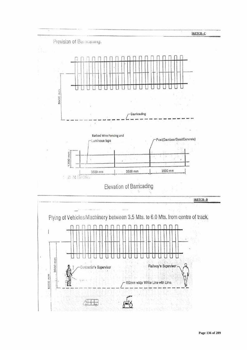
Page 136 of 289
Page 137 of 289
(ii) In case vehicles have to ply or machineries have to work within thiszone, railway’s and contractor’s supervisors be positioned as shownin sketch D except for the following:Instead of a Railway supervisor it would be a responsible and trainedstaff of the Contractor as mentioned in para 14.2.2.1 (ii) above.
(iii) Additional trained staff of the Contractor, as mentioned in para 14.2.2.1(ii) above, shall be posted where turning of vehicles is required duringworking e.g. earth work, bridge work, ballasting etc. Location forreversing vehicles should be nominated and it should be selected insuch away that there is no danger to running trains at such a location.Such trained staff of the Contractor should be available with handflags so that vehicles do not come closer to track by 3.5 meters.Wherever vehicles have to take turn, it should be done in such a waythat the driver is invariably facing the running track at all times.
(iv) Look out men should be posted along the track at a distance of 800meters from location of work with red flag and to whistle in face ofroad vehicles and approaching trains. Look out men shall also besuitably trained staff of Contractor as mentioned in para 14.2.2.1 (ii)above.
(v) In addition to look out men, caution order needs to be issued to trainsand speed restrictions imposed wherever considered necessarythrough Employer.
(vi) Arrangements should be made to protect the track in case of emergencyat work site.
(vii) All temporary arrangements required during execution should be done ina manner that moving dimension is not fringed.
(viii) Individual vehicle/machinery shall not be left unattended at site of work.If it is unavoidable and essential to stable it near running track, it shallbe properly secured and manned even during non working hours withall arrangements to protect the track from infringement.
(ix) Any materials unloaded or shifted along the track should be kept clear ofmoving dimensions and stacked at a specified distance from runningtrack.
(x) Movement of vehicle/working of machineries should be prohibited atnight. However, in case of emergency when night working isunavoidable, adequate lighting shall be provided with all protectionmeasures as mentioned above in full force. All night working near IRtrack shall require Engineer’s prior approval.
(xi) The work site should be suitably demarcated to keep public andpassengers away. Necessary signages, boards, such as “work inprogress” etc should be provided at appropriate location to warnpublic/passengers.
(xii) Contractor’s drivers/operators handling vehicles/machineries shall beissued a fitness certificate by the safety officer of the Contractor aftereducating them about safety norms and after taking assurance inwriting for working within vicinity of railway’s track.
(xiii) While working on cuttings with machineries or when there is movementof vehicles above cutting, if there is possibility of any of the followingcircumstances, work has to be done under block protection:
Page 138 of 289
a) Any possibility exists for machinery/vehicle after toppling/due toloss of control come over track or infringe it.
b) Chance of machineries/vehicles to come within 3.5 meters fromtrack centre though working beyond it.
14.2.2.3 Works being done beyond 6 meters from centre of IR track.No precautions are needed except in cuttings or where the work canaffect train running in any way.
14.2.3 Procedure to be followed for cutting of existing IR formationLocations where it is necessary to cut the existing IR formation for theconstruction of the DFC formation, are classified into the followingtwo categories:a) Where the distance between the centre line of existing IR track andthe proposed DFC track is less than 8 mb) Where the distance between the centre line of existing IR track andthe proposed DFC track is greater than or equal to 8 m
14.2.3.1 Distance between centrelines of IR and DFC track is less than 8m.(1) Such a situation may arise while working in existing IR yards. Insuch cases, if it is agreed with IR to suspend the nearest IR line forthe traffic, the existing IR formation can be cut vertically at a distanceof 3.8 m from the centre line of the proposed DFC track for the depthrequired to provide the formation layers (blanket and prepared subgrade) of the DFC track as per specifications. In case it is not agreedto suspend the traffic on nearest IR line, detailed methodology for thework will be submitted by contractor to the Engineer for the approvaland work will be executed accordingly following all safetyprecautions.(2) Due care and precautions shall be taken to avoid any slippage ofthe cut. In case of any slippage, damage or disturbance of the IRtrack and formation, the Contractor shall rectify and restore the sameto its original configuration at his own cost to the satisfaction of theEngineer.(3) The suspension of the IR line will not be more than two weeks andthis portion of the earthwork shall be completed within this period.(4) This work shall not be carried out during monsoon, during rainydays or when the IR formation is in a saturated condition.
14.2.3.2 Distance between centrelines of IR and DFC track is greaterthan or equal to 8 m.(1) While constructing the bank by the side IR running track, benchingof existing slope shall be done, before new earthwork is taken up, toprovide proper bonding between old and new earthworks. It shouldbe ensured that there is no humus material left on the benched slope.Care need to be taken to avoid entry of rain water into the formationfrom this weak junction to avoid development of weakness information, slope failure, maintenance problems due to unevensettlement.(2) Starting from the toe, benching at every 30cm height shall bedone on the sloped surface of existing IR bank as in sketch below, soas to provide proper amalgamation between old and new earthwork.
Page 139 of 289
14.3 CLEARING AND GRUBBING(1) Unless otherwise directed by the Engineer, the area to be cleared is that
which is occupied by the completed works and stockpile sites, plus aclearance of 2m beyond the toe of embankments and top of cuts.
(2) The Contractor shall ensure that the operations are only carried out within theproject right-of-way limits and only such methods, tools and equipmentswhich will not affect the property outside the limits or objects designated toremain shall be employed.
(3) The area within the specified limits shall be cleared and grubbed of all trees,shrubs, vegetation, stumps, stones, debris, trash, organic matter, any otherobjectionable materials or obstructions except those designated to remainas stated in the contract documents or as directed by the Engineer.
(4) Contractor shall also remove any scattered material such as Rails andSleepers of Indian Railways, if any, and stack it at a location specified byEngineer.
(5) Grubbing is to be carried out to a level of 0.5 m below the natural groundsurface or 1.75 m below the formation level, whichever is deeper as perinstructions of Engineer.
(6) Any depressions and holes shall be filled with suitable soils and compacted.(7) All materials arising from site clearance and preparation work shall be the
property of Employer and the same except objects/materials designated toremain or specified for reuse or salvaging or as otherwise specified by thecontract documents or directed by the Engineer shall be removed from thesite as the work progresses and shall be disposed of in a satisfactory andacceptable manner in locations outside the project limits with the approval ofEngineer.
(8) Such materials should not be permitted to accumulate and the site shall bemaintained in a safe and workman like condition at all times.
(9) Obtaining of all necessary consents, permits and clearances for clearanceand disposal shall be the sole responsibility of the Contractor.
14.4 SETTING OUT(1) The Contractor shall be responsible for the true and proper setting out of the
Works and for the correctness of the position, alignment, levels anddimensions of all parts of the Work.
(2) The Contractor shall establish a system of horizontal and vertical controls inrelation to the reference bench marks and coordinates as specified by theEngineer, as required for the setting out and verifying the position, line,levels and dimensions of the earthworks and drainage works during theexecution.
(3) The Contractor shall keep updated schedules and drawings of suchinformation and shall submit the same to the Engineer as the setting outproceeds.
(4) All bench marks and control points shall be of robust construction, facilitateeasy identification and shall be checked regularly for accuracy, carefully
Page 140 of 289
protected and maintained in good working condition to the satisfaction of theEngineer, till the completion of the contract.
(5) If any of the bench marks or permanent ground markers become displaced ordamaged during the Contract, then the Contractor shall re-establish themimmediately to the satisfaction of the Engineer and provide the Engineerwith the amended position and level details.
(6) The Contractor shall not commence any construction activity at the sitebefore obtaining the approval of the Engineer to the setting out of the Siteboundaries.
(7) The checking of any setting out or any line, level or dimension by theEngineer or the Engineer’s representative shall not in any way relieve theContractor of his responsibility for the correctness thereof.
14.5 EXCAVATION(1) The Contractor shall ensure that the safety and stability of all adjacent
structures is ensured at all times and take suitable precautions against anysoil erosion and water pollution
(2) Excavations shall be carried out to the lines, levels, dimensions and slopes asshown on the drawings or as directed by the Engineer.
(3) The Contractor shall not excavate outside the limits set by the Engineer.Undercutting of slopes will not be permitted under any circumstance
14.6 GROUND PREPARATION(1) Where ever necessary the ground surface shall be scarified, moisture added
as required and compacted so as to ensure a satisfactory foundation for theplacement of formation / prepared sub-grade / blanket.
(2) Any portion of the ground or existing embankment slope steeper than 1v on4h shall be benched in accordance with standard procedures before filling isplaced on it, unless otherwise directed by the Engineer.
(3) In case the ground surface is too soft or deformable to function as asatisfactory base for the placement and compaction of formation / preparedsub-grade / blanket (as applicable), suitable stabilization should be carriedout so that the fill materials can be placed and compacted to the specifieddensity. Details of any such stabilization should be submitted to theEngineer for approval before any stabilization works commence.
(4) Any foundation treatment required for High Embankments shall be carried outin accordance with the designs, material specifications, drawings andmethodology as approved by the Engineer.
(5) The construction of any section of formation / prepared sub-grade / blanket(as applicable) shall not be commenced until the foundation for that sectionhas been cleared by the Engineer and ground levels recorded jointly.
14.7 FILLING(1) Materials arising from site clearance and preparation work shall be subject to
relevant acceptability tests to assess its suitability for re-use on site orlandfill waste acceptance criteria if applicable. The fill material shall be
Page 141 of 289
placed, spread, graded and compacted in layers of uniform quality andthickness, parallel to the camber and grade for the full width of the cross-section unless specified otherwise or approved otherwise by the Engineer.
(2) The movement of all construction vehicles and other traffic shall bedistributed over the full width of the filling area, so as not to damage oroverstress the construction.
(3) Damage by construction plant and other vehicular traffic shall be repaired bythe Contractor to the satisfaction of the Engineer. Successive layers shallnot be placed until the layer under construction has been thoroughlycompacted, tested and passed by the Engineer.
(4) Additional filling width of 500 mm shall be placed on either side to ensureproper compaction of the fill at the edges, with the extra soil later cut anddressed to avoid any loose earth on the slopes.
(5) In the absence of field compaction trials, the maximum compacted liftthickness shall be limited to 200mm.
(6) The Engineer may allow higher lift thickness, provided the Contractorsatisfactorily demonstrates the efficacy of the compaction equipment andmethodology through field compaction trials.
(7) Field compaction trials shall be in accordance with RDSO guidelines.(8) Moisture content of fill materials as placed shall be uniform throughout the lift
and shall be within the limits specified in accordance with IS:2720:Part 8:1983 or approved Design and Drawings of formation.
(9) Each lift of fill shall be compacted using appropriate equipment and standardprocedures as agreed with the Engineer, so that the specified relativecompaction is achieved uniformly and throughout the full depth of the layer.
(10) For formation, the minimum relative compaction with respect to the maximumdry density shall be determined in accordance with IS:2720: Part 8:1983 orapproved Design and drawings of formation.
(11) In case any lot or part of the earthworks has failed to meet the acceptancecriteria during quality control checks, the entire lot or part shall be rectified tothe satisfaction of the Engineer.
(12) The Contractor shall investigate all such instances of poor quality of work,identify the reasons and shall take the necessary corrective action.
(13) In case a layer or portion of the earthworks which has been completed andaccepted by the Engineer is subsequently damaged or deteriorated at anytime till the completion of the contract, the same shall be rectified by theContractor to the satisfaction of the Engineer.
14.8 PREPARED SUB-GRADE(1) The construction procedures for prepared sub-grade are similar to that used
for embankment fill, with the additional requirements of higher relativecompaction and frequency of quality control testing.
(2) For prepared sub-grade, the minimum relative compaction with respect to themaximum dry density determined in accordance with IS:2720: Part 8:1983shall be as per GE - 14 or as per the approved Design and Drawings offormation.
Page 142 of 289
14.9 BLANKET(1) The construction procedures for blanket are similar to that for embankment
fill, with the additional requirements of higher relative compaction andfrequency of quality control testing.
(2) For blanket, the minimum relative compaction with respect to the maximumdry density determined in accordance with IS:2720: Part 8:1983 shall be asper GE - 14 or as per the approved Design and Drawings of formation.
14.10FINISHING(1) The top surface and side slopes of the formation shall be shaped, dressed
and finished to conform to the alignment, levels, cross-sections, dimensionsand cross slopes shown on the approved construction Drawings and to therequirements and tolerances stated in this specification. Ballast bed shall belaid only after the top surface has been cleared by the Engineer.
14.11RETAINING STRUCTURES(1) Method and sequence of construction of retaining walls, drainage bay and
backfilling shall be in accordance with approved Design and Drawings forthis purpose.
(2) The sequence of activities shall be well-coordinated with the construction ofearthworks.
(3) Quality control of concrete shall conform to the requirements of IS 456.14.12EROSION CONTROL(1) All erosion control arrangements including revetment/ sodding - type of soil,
source of sods, anchoring arrangements, fertilizer usage, small gap fillingarrangement etc. shall form part of Design of Embankment/formation andapproved before execution at site.
(2) The surface to be sodded shall be checked to ensure that it has beenconstructed to the required slope and cross-sections.
(3) The surface shall be freed of all stones larger than 50 mm, and any otherundesirable objects or materials.
(4) Where the surface to be sodded consists of soils suitable for sustainingvegetation, the soil should be scarified in a direction parallel to the alignmentto a depth of about 50mm.
(5) Where the surface to be sodded consist of soils which cannot be improvedsufficiently to support good plant growth by the addition of fertilizers and/orother additives, the surface shall be scarified and a 75 mm thick layer oftopsoil shall be placed and compacted using a light-weight compactor.
(6) The surface of the top soil shall be scarified in a direction parallel to thealignment to a depth of about 50mm.
(7) Where ever required fertilizer and additives like lime etc. shall be spreaduniformly on the prepared surface and worked into the soil. The type andquantum of fertilizer and any other additives and method of application shallbe suitable for the sods.
(8) Immediately prior to implanting sods, the soil shall be uniformly moist to adepth of 150 mm.
Page 143 of 289
(9) If this condition is not met by natural means, the Contractor shall carryoutwatering as directed by the Engineer.
(10) The final prepared surface shall be made slightly rough to ensure a goodpenetration of roots into the soil.
(11) Sods once harvested or delivered from a nursery, shall not be allowed to dryout. Sods shall be planted within 24 hours of being removed from the soil orgrowing medium, unless proper storage arrangements can be made by theContractor.
(12) Sods shall be laid in regular rows with staggered joints and with individualpieces closely butting against each other without any openly visible gaps orany overlaps between pieces.
(13) The first row of sods, where it is possible, shall be laid in a straight line andstarting at the bottom of the slope.
(14) Any gaps shall be planted with a sod cut to the gap size or, filled with topsoil.
(15) Sods shall be suitably tamped to ensure a good bond with the underlying soil.(16) Where the slope is 2 (horizontal) to 1 (vertical) or steeper, the sods shall be
secured against slippage by anchoring them with stakes, pegs or pins drivenalmost vertically into the soil to be almost flush with the sods.
(17) The type, length and spacing of the anchoring fixtures shall be chosen by theContractor to ensure stability of slopes.
(18) After completion of planting, the surface shall be cleaned off all excess soil,sods and any other undesirable objects or materials.
(19) The sods shall be well-watered after planting and not be allowed todeteriorate due to lack of moisture.
(20) The Contractor shall maintain the sodded areas by watering, fertilizing,replanting etc. as required to establish a uniform and healthy turf free oferoded or bare areas until the completion of the contract period.
(21) For High Embankment or at certain location, earth slopes may warrantrevetment works which shall be carried out as per the approved Drawingsand methodology as per 14.12(1) above.
14.13DRAINAGE(1) Methodology, construction and sequence of construction of side drains shall
be carried out in accordance with Good For Construction Drawings.(2) The level at any point on the surface of the lining shall be within ± 20mm of
the design levels.(3) For other types of drains, the construction shall be carried out as per the
Drawings along with methodology agreed by the Engineer.14.14 RCC Pipes for Signalling and Communication cables
While doing earthwork Contractor shall make provisions of suitable RCCpipes at the following locations at his own cost including pipes:-
i) At Level Crossing Gatesa) 2X200mm dia RCC pipes across the formation near the gate lodge.

Page 144 of 289
b) 1X200mm RCC pipe across the road surface near the lifting barrier.ii)At approach of RFO
1 x 200 mm dia RCC pipes across the formation at both approach of theRFO.
15.0 QUALITY CONTROL15.1 GENERAL(1) The Contractor shall be responsible for quality control including all testing,
checking and measurement.(2) The Employer or the Engineer may carryout independent quality control tests
through his own personnel or other agencies.(3) The Contractor shall provide all necessary assistance and cooperation to the
Employer and the Engineer in obtaining samples for laboratory tests orcarrying out field tests.
15.2 FIELD GEOTECHNICAL ENGINEERING LABORATORY(1) The Contractor shall establish and operate or hire approved field geotechnical
laboratories adequately equipped to carry out all required in-situ andlaboratory tests to assess the nature and properties of the sub-soils, monitorand control the properties of the blanket and borrow materials and finishedearthworks which are of significance to design, construction andperformance of the formation and earthworks.
(2) The number and location of the laboratories shall be finalized in consultationwith the Engineer on the basis of the volume of earthworks, schedule ofcompletion, frequency of testing etc.
(3) The laboratories shall have all the required facilities, equipment andcompetent staff for carrying out all the tests which are required for purposeof quality control.
(4) The number of sets of equipment for each test and the number of staffdeployed shall be adequate to ensure the specified frequency of testingwithout adversely impacting the time schedule of construction
(5) All equipment and accessories shall conform to the appropriate Indian orapproved international standard, from a reputed manufacturer and shall bein good working condition.
(6) Wherever applicable, the equipments or parts shall be calibrated inaccordance with established standards and practices.
(7) Each laboratory shall be furnished with an original set of the latest version ofall relevant standards for all the required test methods
(8) Contractor shall systematically maintain records of all tests in a formatapproved by the Engineer.
(9) The Contractor shall ensure unhindered access at all times to Employer,Engineer or their representatives to inspect the laboratory, equipments andsamples, to witness the tests and to verify the records.
(10) Employer and the Engineer shall have the right to use the field laboratory tomake independent assessments of the accuracy and repeatability of the
Page 145 of 289
tests and verification of the results by their personnel or representativesfrom time to time.
15.3 QUALITY CHECK ON MATERIALS(1) The tests to be conducted and their frequency for materials used as blanket,
prepared sub-grade, formation etc. shall be as specified in IS 2720.15.4 QUALITY CONTROL OF COMPACTION(1) Control on compaction shall be exercised on each lift of compacted materials
by taking measurements of the dry density and moisture content of thecompacted fill at representative locations selected at random.
(2) Each sample constituting a set of measurements representing a part or lot ofthe lift shall comprise a minimum of 6 individual test locations (which may beincreased to 10 if considerable variations in individual test results areobserved).
(3) The frequency of sampling will be as per approved specification of earthwork.(4) The benchmark test method for dry density shall be the sand replacement
method in accordance with IS:2720: Part-28.(5) The benchmark test method for moisture content shall be oven-drying in
accordance with IS:2720: Part 2.(6) Calcium carbide gas pressure moisture tester may be used subject to the
condition that reliable soil-specific correlations are established with resultsobtained in accordance with IS:2720: Part 2
(7) Nuclear gauge method may be used for the determination of both density andmoisture content subject to the following conditions and with prior approvalof the Engineer:a) The test is performed by a qualified and competent operator well-trained
in the use of the equipment;b) Reliable soil-specific correlations are established with density
measurements in accordance with IS:2720:Part-28 and moisturecontent measurements in accordance with IS:2720: Part 2;
c) The equipment is standardized and calibrated in accordance withstandard procedures;
d) The method shall not be used in locations close to objects or structureswhich can induce incorrect readings.
(8) Use of any methods other than listed above shall be only with the permissionof the Engineer and provided that the method is demonstrated to be suitablefor the soil types and compaction methods used, gives reliable resultsconsistently and offers significant advantages over the standard methods interms of speed, frequency of sampling, automation, safety etc.
(9) Control shall not be based on the result of any one individual test but basedon the mean value obtained for a sample (comprising a set of minimum of 6to 10 individual test locations)
15.5 TOLERANCES FOR FINISHED WORKS(1) The top width of the formation (measured at the top of the blanket) and the
bottom width of cuttings shall not be less than the specified width
Page 146 of 289
(2) The finished surface of the formation (top of blanket) shall be constructed tothe following tolerances:a) The finished level shall be within + 0mm and - 25mm of the level shown
on Drawingsb) The deviation of the finished surface from a 3m straight edge laid on the
surface parallel to the alignment shall not exceed 15mm.c) The deviation of the finished surface from a 3m straight edge laid on the
surface perpendicular to the alignment shall not exceed 15mm.d) The cross-slope of the formation shall not deviate from the cross-slope
shown of the drawings by more than 3mm per metre.(3) The cross-slope of the finished surface of cuttings shall not deviate from the
cross-slope shown of the Drawings by more than 3mm per metre.(4) Side slopes of fills and cuts shall not be steeper than the slopes shown on
Drawings(5) The finished surface of the prepared sub-grade and blanket shall not have
depressions or ridges which could hold water or prevent proper drainage15.6 COMPLETION AND ACCEPTANCE(1) The Contractor shall complete the earthworks, erosion control and drainage
works in accordance with the drawings agreed by the Engineer.(2) The Contractor shall carryout a final survey of the completed earthworks to
certify that the earthworks have been placed within the specified tolerancesto the design alignment and grades and furnish the results to the Engineer.
(3) The Contractor shall provide As-Built Drawings for the earthworks, erosioncontrol and drainage works
(4) The Contractor shall maintain the earthworks, erosion control and drainageworks for the Defect Notification Period as specified in the contract.
(5) The Contractor shall provide a handover package containing, but not limitedto, the following data:a) Subsoil investigation reportsb) All records related to material testing and quality control including
request for inspections and test reports.c) Construction records and feedback reports, instrumentation and
performance monitoring details.16.0 CONSTRUCTION-BRIDGES(1) The design shall be capable of allowing the construction to be carried out in
the minimum time possible and to the required quality standard.(2) The construction methodology to be adopted for RFO shall be such as to
allow unhindered and safe movement of existing rail traffic with minimumnumbers and duration of traffic blocks and incorporating suitable temporaryarrangements conducive to working under running traffic.
(3) Where track closures (traffic blocks) are required for construction, theContractor is responsible for the coordination with IR and will be assisted asapplicable by the Employer/Engineer.

Page 147 of 289
(4) When the Design has assumed a particular sequence of construction in orderto account for the construction load effects, the same sequence is to befollowed during the construction.
(5) All structural materials/products like non-pre-stressing and pre-stressingsteel, pre-stressing anchorage system, bearings, expansion joints, etc shallbe procured from IR/RDSO approved suppliers or from other approvedsuppliers with the approval of Engineer.
(6) Concreting process all structures including insitu, transported, ready mixconcrete, batch mixing plant etc. for manufacturing, supplying, placementand testing shall always comply with the provisions of IS 456 or otherapplicable codes. Any deviation shall have prior consent of the Engineer.Curing of concrete shall be ensured as per the applicable codes of practice.
17.0 CONSTRUCTION - Ballast Bed(1) The ballast duly inspected by the Engineer shall be brought at site such that
it is free from quarry dust and any other contamination.(2) Ballast bed shall be laid directly on to the prepared formation and support
structure like bridge deck slabs, using methods that keep the amount of roadtraffic over the formation and support structures to a minimum and thatmake no damage to the utilities and other structures as existing at or nearthe site.
(3) The ballast shall be laid in loose layers of maximum 100mm thickness eachand compacted by a minimum of 4 passes of a smooth vibrating rollerhaving a minimum static load of 4kN per 100mm of width or similar.
(4) The ballast bed shall be laid so as to make an initial neat ballast cushion ofapprox. 200 mm below the bottom of the sleepers after the requiredrolling.
(5) The ballast bed shall be neatly dressed up so that there is no obstruction toworking of the plant and machinery for further activities of rail spreading,sleeper laying etc.
(6) On completion of the ballast bed a survey shall be undertaken todemonstrate the acceptability of the bottom ballast for track laying. Tracklaying is not in the scope of the present work. The prepared ballast bed shallbe inspected and approved by the Engineer.
(7) The contractor shall provide the balance quantity of ballast in the stacks atlocations as approved by the engineer.
(8) In case spare land is available with the Employer the same can be handedover to the Contractor free of cost for the purpose of establishing temporaryconstruction depot(s)/stacking of Ballast. However, whenever Employerrequires this portion of land back, the same shall be handed over to theEmployer with a month’s notice at no extra cost/compensation to theContractor.
17.1 FENCINGThe fencing shall be constructed as per the agreed Drawings andmethodology. .
17.2 TEMPORARY WORKS
Page 148 of 289
(1) The land, as required for all the temporary arrangements and works includingthe requirement of borrow pits, quarrying, etc. shall be arranged by theContractor by himself at his own cost. While extracting material from theborrow pits he shall ensure compliance of applicable provisions as perEnvironment Management Plan (EMP) of DFCC.
(2) All temporary works shall be removed on completion of permanent works, oras directed by the Engineer.
18.0 OTHER ENGINEERING WORKS(1) Works of approach road construction, fencing, Goods platforms, modification
of level crossing gates etc. shall be done as per the drawings andprocedures agreed by the Engineer based upon the Design criteriamentioned in Volume 4, Employer’s Requirement, Part 2 of the BiddingDocument.
19.0TESTING19.1 GENERAL(1) The Contractor shall provide and perform all forms of testing procedures
applicable to the Works and various components including all necessaryfactory, site and acceptance tests required therein. Until the time the Worksare taken over by the Employer, Contractor shall maintain the same in amanner so as to continuously meet the acceptance criteria for all aspects,as per the requirements mentioned in the Employer’s Requirement, Part 2of Bidding Documents. Contractor shall make a consolidated list of all thetests required for Testing alongwith the testing procedures and applicablecodes/ manuals and submit the same to the Engineer for enabling a jointprogram of testing.
(2) All testing procedures shall be submitted at least twenty eight (28) days priorto conducting any test. The testing procedures shall show unambiguouslythe extent of testing covered by each submission, the method of testing, theacceptance criteria, the relevant drawing (or modification) status and thelocation.
(3) The testing procedures shall be submitted, as required, by the Contractorduring the duration of the contract to reflect changes in design of civil works,interface systems or the identification of additional testing requirements.
(4) The Engineer, the Employer's Personnel and authorized agencies shall at allreasonable times:
(a) Have full access to all parts of the Site and to all places from whichnatural Materials are being obtained, and
(b) During production, manufacture and construction (at the Site andelsewhere), be entitled to examine, inspect, measure and test thematerials and workmanship, and to check the progress of manufactureof Plant and production and manufacture of Materials.
(c) The Contractor shall give them full opportunity to carry out theseactivities, including providing access, facilities, permissions and safetyequipment. No such activity shall relieve the Contractor from anyobligation or responsibility. They shall be provided the facilities formonitoring all tests and have access to all testing records.
Page 149 of 289
(5) Ample time shall be allowed within the testing programmes for necessaryalterations to equipment, systems and designs to be undertaken,engagement of Engineer, together with re-testing .
(6) All costs associated with the testing as above shall be borne by theContractor, unless otherwise specified, including the services of anyspecialised personnel or independent assessors concerned to the workdone by him. The Contractor shall also bear any expenses incurred due toresetting caused by defects or failure of equipment to meet the requirementsof the Contract in the first instance for the works done by him.
(7) Unless agreed in writing by the Engineer, the personnel engaged on testingshall be independent of those directly engaged in the design or installationof the same equipment.
(8) All testing equipment shall carry an appropriate and valid calibration labels.(9) Examination of Works before covering up: No work or part of work shall be
covered up or put out of view, without the prior approval of the Engineer orthe Engineer’s Representative. The Contractor shall uncover any part orparts of the Works, or make openings in or through the same, as theEngineer may from time to time direct, and shall reinstate and make goodsuch part or parts, to the satisfaction of the Engineer.
(10) If any defect or damage is one requiring immediate attention from a safety,environment or operational aspect, the Engineer has the authority toproceed with the rectification in any manner suitable and deduct the costfrom the next due interim payment.
19.2 BATCHES, SAMPLES AND SPECIMENS(1) A batch of material is a specified quantity of the material that satisfies the
specified conditions.(2) If one of the specified conditions is that the material is delivered to the Site at
the same time, then material delivered to the Site over a period of a fewdays may be considered as part of the same batch if in the opinion of theEngineer there is sufficient proof that the other specified conditions applyingto the batch apply to all of the material delivered over the period.
(3) A sample is a specified quantity of material that is taken from a batch fortesting and which consists of a specified amount, or a specified number ofpieces or units, of the material.
(4) A specimen is the portion of a sample that is to be tested.19.3 SAMPLES FOR TESTING(1) Samples shall be of sufficient size and in accordance with relevant standards
to carry out all specified tests.(2) Samples taken on the Site shall be selected by, and taken in the presence of,
the Engineer and shall be suitably marked for their identification. Anidentification marking system should be evolved at the start of works inconsultation with the Engineer.
(3) Samples shall be protected, handled and stored in such a manner that theyare not damaged or contaminated and such that the properties of thesample do not change.
Page 150 of 289
(4) Samples shall be delivered by the Contractor, under the supervision of theEngineer, to the specified place of testing. Samples on which non-destructive tests have been carried out shall be collected from the place oftesting after testing and delivered to the Site or other locations instructed bythe Engineer.
(5) Samples which have been tested may be incorporated in the PermanentWorks provided that:(a) the sample complies with the specified requirements;(b) the sample is not damaged; and(c) the sample is not required to be retained under any other provision of
the Contract.(d) Engineer is in agreement with the proposal of Contractor.
(6) Additional samples shall be provided for testing if in the opinion of theEngineer:a) material previously tested no longer complies with the specified
requirements; orb) material has been handled or stored in such a manner that it may not
comply with the specified requirements.19.4 TESTING(1) The Contractor shall be responsible for all on-site and off-site testing and for
all in-situ testing.(2) All appropriate laboratory tests shall be carried out in the Contractor's
laboratory, unless otherwise permitted or required by the Engineer.(3) Where the laboratory is not appropriately equipped and/or staffed for some
tests, or if agreed to by the Engineer, tests may be carried out in otherlaboratories provided that:a) they are accredited for the relevant work to a standard acceptable to the
Engineer , and
b) particulars of the proposed laboratory are submitted to the Engineer forhis consent.
c) Prior intimation to the Engineer shall be given regarding the date/timeand location of testing.
(4) In-situ tests shall be done in the presence of the Engineer.(5) Equipment, apparatus and materials for in-situ tests and laboratory
compliance tests carried out by the Contractor shall be provided by theContractor.
(6) The equipment and apparatus shall be maintained by the Contractor andshall be calibrated before the testing starts and at regular intervals aspermitted by the Engineer.
(7) The equipment, apparatus and materials for in-the situ tests shall be removedby the Contractor as soon as practicable after the testing is complete.
Page 151 of 289
(8) The Contractor shall be entitled in all cases to attend the testing carried out inthe other laboratories, to inspect the calibration certificates of the testingmachines and to undertake the testing on counterpart samples.
(9) Testing of such samples shall be undertaken in laboratories and particulars ofthe laboratory proposed shall be submitted to the Engineer for consent priorto the testing.
(10) Attendance on tests, including that by the Engineer, Contractor and Designer,shall be as laid down in the Quality Assurance procedures.
19.5 COMPLIANCE OF BATCH(1) The results of tests on samples or specimens shall be considered to
represent the whole batch from which the sample was taken.(2) A batch shall be considered as complying with the specified requirements for
a material if the results of specific tests of the specified properties complywith the specified requirements for the properties.
(3) If additional tests are permitted or required by the Engineer but separatecompliance criteria for the additional tests are not stated in the Contract, theEngineer shall determine if the batch complies with the specifiedrequirements for the material on the basis of the results of all tests or maydecide to get special tests undertaken.
(4) The cost of such tests shall be borne by the Contractor.19.6 RECORDS OF TESTS(1) Records of in-situ tests and laboratory compliance tests carried out by the
Contractor shall be kept by the Contractor on the Site and a report shall besubmitted to the Engineer within seven (7) days, or such other time stated inthe Contract or in the Quality Assurance Programme, after completion ofeach test.
(2) In addition to any other requirements, the report shall contain the followingdetails:a) material or part of the Works tested;b) location of the batch from which the samples were taken or location of
the part of the Works;c) place of testing;d) date and time of tests;e) weather conditions in the case of in-situ tests;f) technical personnel supervising or carrying out the tests;g) size and description of samples and specimens;h) method of sampling;i) properties tested;j) method of testing;k) readings and measurements taken during the tests;l) test results, including any calculations and graphs;

Page 152 of 289
m) specified acceptance criteria; andn) other details stated in the Contract.
(3) Reports of tests shall be signed by the Contractors Site Representative or hisassistant, or by another representative authorised by the Contractor.
(4) If requested by the Contractor records of tests carried out by the Employer'sstaff or by the Engineer shall be given to the Contractor.
19.7 PRODUCTION TESTS (AT WORKS)(1) Should the Contract include any equipment not previously proven in service
the Contractor shall undertake a thorough testing of pre-production units tothe satisfaction of the Engineer.
(2) The Contractor shall identify any equipment in this category, or equipmentwhich differs significantly from that already in service elsewhere.
(3) All materials, components, sub-assemblies, unit assemblies (includingsoftware, cables and wiring) shall be subject to testing and certification.Notification of these Tests shall be submitted to the Engineer twenty eight(28) days in advance of carrying out any Tests.
(4) The Engineer will then determine which, if any, items may be accepted basedon previous supply or experience.
(5) Works Tests shall include wherever required, but not be limited to:a) Physical inspectionb) Dimension checkc) Electrical checkd) Calibratione) Output checkf) Operational performanceg) Full Load testh) Non-destructive test to assess integrity or strength of parts
(6) Where processor based equipment is to be used, then the works Test shallinclude also verification of software used in this application.
19.8 POST INSTALLATION TESTS (ON SITE)(1) During and on completion of the installation, the Contractor shall undertake
testing of all the permanent works in accordance with the overall testingprogramme.
(2) These tests shall culminate in functional tests to verify the correct operation offull apparatus and, where appropriate, correct response to the respectivecontrol and physical operation of the device/ components.
19.9 ACCEPTANCE TESTS(1) The Contractor shall prepare and organise a comprehensive programme of
acceptance tests to demonstrate to the Engineer that all systems, sub-systems and apparatus defined under the Contract meet the specifiedperformance requirements in all respects.
Page 153 of 289
(2) These tests shall be conducted by the Contractor in the presence of theEngineer.
19.10 TEST ON COMPLETION(1) The results of the Testing shall be compiled and evaluated by the Engineer
and the Contractor.(2) If the Works, or a part thereof, or a section, fail to pass the Testing, the
Engineer shall require such failed tests, to be repeated under the sameterms and conditions. If such failure and retesting result from a default of theContractor and cause the Employer to incur additional costs, the same shallbe recoverable from the Contractor by the Employer, and may be deductedby the Employer from any monies due, or to become due, to the Contractor.
(3) If the Works, or a part thereof, or a Section, fail to pass Testing and theContractor in consequence proposes to make any adjustment ormodification to the Works or a part thereof, or a section, the Engineer mayinstruct the Contractor to carry out such adjustment or modification, at hisown cost or to other contractor(s) if the item(s) of Works is attributable toother contractor(s) and to satisfy the requirements of Testing within suchtime as the Engineer may deem to be reasonable.
(4) The Contractor along with others shall carry out all statutory tests and trials,under the supervision of the Engineer, necessary for obtaining sanction ofthe competent authority, if required, for opening the railway system.
(5) During testing, the Contractor shall be required to carry out coordination withall interfacing contractors and agencies as and if required.
20.0RECORDS20.1 DRAWINGS PRODUCED BY THE CONTRACTOR(1) Drawings produced by the Contractor including Drawings of Site layouts,
Temporary Works, etc. for submission to the Engineer shall generally be toISO A1 size.
(2) They shall display a title block with the information as detailed in Part 2“Employer’s Requirement, Section V, Volume 6, Appendix 7 - Drawingand CAD Standards”.
(3) The number of copies to be submitted to the Engineer shall be as stated inthe Contract, or as required by Engineer.
(4) The Contractor shall provide five sets of As Built Drawings along with readonly electronic version of the same on CD/DVD to the Engineer.
20.2 PROGRESS PHOTOGRAPHS AND VIDEOGRAPHY(1) The Contractor shall provide monthly progress photographs which have been
properly recorded to show the progress of the works to the Engineer.(2) The photographs, of not less than 20 in number per month, shall be taken on
locations agreed with the Engineer to record the exact progress of theWorks. All important events shall be photographed.
(3) Two sets of photographs shall be provided on CD ROM format with two setsof colour prints of 175 mm x 125 mm size in albums duly labelled.
Page 154 of 289
(4) The Contractor shall mount each set of each month's progress photographsin a separate album of a type to which the Engineer has given his consent,and shall provide for each photograph two typed self-adhesive labels, one ofwhich shall be mounted immediately below the photograph and one on theback of the photograph.
(5) Each label shall record the location, a brief description of the progressrecorded and the date on which the photograph was taken.
(6) All photographs shall be taken by a skilled photographer.(7) Photo processing shall be carried out by a competent processing firm to the
satisfaction of the Engineer.(8) The Contractor shall ensure that no photography is permitted on the Site
without the consent of the Engineer.(9) Important events, construction activities, working of new machinery, weather
effects or any occasion advised by the Engineer shall be video graphed.The recording shall be done or converted to appropriate format andpresented in a CD/DVD with appropriate voice recording describing theevent.
20.3 RECORDS OF WAGE RATESThe Contractor shall keep monthly records of the average, high and lowwage rates for each trade/tradesman employed on the Site and recordsshall be made available to the Engineer during inspection.
20.4 REGISTERS FOR MAINTENANCE(1) After completion of works, Contractor shall produce the following registers
similar to the ones in use over IR and as per IRPWM, IRBM, IRWM, IREngg Code and other relevant codes and manuals as under:-i) Bridge Register (2 sets)ii) Level Crossingiii) Land Boundaryiv) L-Sectionv) Index Plan and Sectionvi) Earthworksvii) The above list is not exhaustive and Contractor is required to prepare an
Asset database which identifies all infrastructures along the route.This database shall be expandable to allow maintenancerequirements to be called up together with an Asset Managementand Planned Preventative Maintenance Schedule of DFCC.
viii) Any other registers as directed by Engineer to be used duringmaintenance.
21.0MATERIALS(1) Materials and goods for inclusion in the Permanent Works shall be new
unless the Engineer has consented otherwise. Preference shall be given tolocal materials where available.
Page 155 of 289
(2) Certificates of tests by manufacturers which are to be submitted to theEngineer shall be current and shall relate to the batch of material deliveredto the Site.
(3) Certified true copies of certificates may be submitted if the original certificatescould not be obtained from the manufacturer.
(4) Parts of materials which are to be assembled on the Site shall be marked toidentify the different parts.
(5) Materials which are specified by means of trade or proprietary names may besubstituted by materials from a different manufacturer which has receivedthe consent of the Engineer provided that the materials are of the same orbetter quality and comply with the specified requirements.
(6) Samples of materials submitted to the Engineer for information or consentshall be kept on the Site and shall not be returned to the Contractor or usedin the Permanent Works unless permitted by the Engineer.
(7) The samples shall be used as a mean of comparison which the Engineershall use to determine the quality of the materials subsequently delivered.Materials delivered to the Site for use in the Permanent Works shall be ofthe same or better quality as the samples which have received consent.
22.0 PROVISION AND DISPOSAL OF EARTHWORKS MATERIAL(1) The Contractor shall be responsible for the provision of all classes of
earthworks material required for the Works, whether sourced from theexcavations within the Work Area or obtained from any other sources, whichare located outside the Site, for which the Engineer has given the consent.
(2) For fill or dumping sites, the Contractor shall prepare a land plan with detailsof surface drainage requirements, final formation levels, spreading andcompaction of the fill during dumping acceptable to the Engineer.
(3) The Contractor shall also provide security for such sites. The dumping sites tobe used by the Contractor shall be as directed by the Engineer.
(4) All excavated material, excluding waste material, bentonite fluid and bentonitecontaminated material shall be disposed of at the appointed site only.
(5) This material shall be placed and compacted in accordance with theconstruction specification for earth works or as otherwise directed by theEngineer .
(6) The disposal of waste material, bentonite fluid and material contaminated withbentonite shall be the sole responsibility of the Contractor and thesematerials shall be disposed off by the Contractor at an approved location athis own cost.
(7) The dumping sites provided by the Engineer, if any, shall not be used fordisposal of waste material, bentonite fluid or material contaminated withbentonite.
23.0 DEFECT NOTIFICATION PERIOD(1) After the Works are taken over by the Employer in terms of para 10.1 of
General conditions of Contract it will be followed by the Defect NotificationPeriod of two years.

Page 156 of 289
During this period Contractor shall replace/ remedy the defects occurringunder normal usage of Works by the Employer, except for normal wear andtear under such usage.
Maintenance activities to be done during Defect Liability Period shall bedone by the Employer at its own cost.
*****
Page 157 of 289
Section V. Employer’s Requirement
Volume 6 – Appendices
CONTENTS
APPENDIX 1 UTILITIESAPPENDIX 2 WORKS AREAS AND CONTRACT STAGESAPPENDIX 3 DESIGN AND CONSTRUCTION INTERFACESAPPENDIX 4 PROJECT PROGRAM REQUIREMENTSAPPENDIX 5 MONTHLY PROGRESS REPORTSAPPENDIX 6 QUALITY ASSURANCEAPPENDIX 7 DRAWING AND CAD STANDARDSAPPENDIX 8 TEMPORARY POWER SUPPLYAPPENDIX 9 PROJECT CALENDARAPPENDIX 10 FIRST AID BASEAPPENDIX 11 DESIGN CERTIFICATEAPPENDIX 12 SITE SAFETY PLAN AND ENVIRONMENTAL PROTECTION
REQUIREMNET.APPENDIX 13 TRAFFICE BLOCK (POSSESSION) MANAGEMENTAPPENDIX 14 DESIGN STANDARDSAPPENDIX 15 ENGINEER’S ACCOMMODATION

Page 158 of 289
APPENDIX 1:UTILITIES
Page 159 of 289
1.0 UTILITIES1.1 General
(1) The Bidder for this Work is required to remove all chartered and uncharteredutilities coming in the way of alignment. Chartered utilities are listed in Part4 – Reference documents -Site Data of Bidding documents andContractor shall not be paid extra for removal of chartered utilities. Work ofremoval of unchartered utilities shall be treated as a Variation to theContract and shall be dealt as per the provisions for dealing with Variationsin Contract. Contractor shall be paid as per the actual work done for removalof unchartered utilities based on the Variation approved by the Engineer, oncase to case basis.
(2) Before removing any utilities Contractor should submit a utility diversionreport to the Engineer with the following details, for approval :-a) location of utility;b) name and address of the utility owner;c) nature and sizes of the utilities;d) description and condition of utility;e) temporary or permanent supports required; andf) temporary or permanent diversion requiredg) use of specific construction methods to complete the underground
structures around and below the utilities including support of the utilitiesduring construction.
h) Materials required for removing / relocating the utility.i) Time required for removing / relocating the utility.j) For unchartered utilities - date on which the utilities were encountered
and the cost involved based upon the proposed Variation to Contract forremoval of such utilities.
(3) A utility diversion plan with schedule of utility removal/ relocation shall beprepared by the Contractor and submitted along with the preliminary Designfor all utilities. Unchartered utilities shall be included as soon as these areencountered by the Contractor and the plan updated accordingly. TheContractor shall take into consideration the time taken for utility diversionsand shall take all steps to enable the utility diversions to proceed inaccordance with the overall Works programme.
(4) The Contractor shall set up and manage a utility liaison group of experiencedpersonnel for the duration of the Contract which shall maintain close liaisonwith the utility owners and undertakings.
(5) The Contractor shall immediately inform the Engineer and the utility agenciesof any
a) damage to utilities;b) leakage of utilities;c) discovery of utilities not previously identified.
(6) Work of utility removal shall deem to include the following and shall be doneby the Contractor at his own cost for this Work:-

Page 160 of 289
a) Identifying the utilities, their owner and agencies involved in grantingclearance for their removal/ relocation.
b) Preparing plans/ drawings/ applications for their removal/ relocation.c) Liaisonimg and obtaining necessary clearances from the concerned
authorities. Employer shall assist the Contractor in this regard.d) Carrying out the removal/ relocation of utilities, to the specified
locations within or outside the Site, including all under and overground structures, temporary or permanent diversions etc. requiredas per the clearances of concerned authorities/ utility owners.
e) Providing temporary/ permanent supports and protection as per themethods proposed by the Contractor and agreed by the utility ownerand Engineer wherever required for the safety and security of theutility service and public.
f) The work for relocation /modification of all utilities shall be done asper relevant latest standards and specifications prescribed by theconcerned utility owner/ authority. It will be the responsibility of theContractor to obtain such standards/ specifications from theconcerned utility owner/ authority.
g) Arranging inspection /testing of modified /relocated utilities by theconcerned authorities/ utility owners and preparation of test reportsand any other reports required under applicable rules, Acts,regulations of such authorities/ utility owners.
h) Dismantling of old utilities and disposing off the released material asper agreement arrived at with the owners of the utilities.
i) Handing over of relocated / modified utilities to the owners of utilities/agencies with ‘no objection certification’ from them.
(8) The Contractor shall consider following stipulations while relocating /modifying electrical utilities.
a) Regulations for power line crossings of Railway tracks as per IndianRailways Manual of AC Traction (Vol.-II, Part-II, and Appendix-IV)read along with Correction Slip no.-18 dated Jan 19, 2009 will befollowed by the Contractor.
b) Contractor/ Sub contractor (engaged by the Contractor for electricalworks) should have an electrical contractor license as per IndianElectricity Act 2003.
(9) No extra payment of any money required to be paid by the Contractor to theutilities owner for supervision charges or on any other account shall bepayable by the Employer.
(10) Records of the existing utilities encountered shall be kept by the Contractoron the Site and a copy provided to the Engineer. The records shall containthe following details:-
a) location of utility;b) date on which the utilities were encountered;c) date on which the utilities were removed/ relocated;d) nature and sizes of the utilities;

Page 161 of 289
e) condition of utility;f) temporary or permanent supports provided; andg) diversions made –temporary or permanenth) details of materials usedi) relevant photographs/ drawings of various stagesj) clearances of utility owners/ relevant authorities at various stages.
(11) The Contractor shall include the details (completed plans showing clearancesof relevant authorities and owners, location, ownership, size and material) ofall such utilities in the As Built Drawings.
(12) The Contractor shall allow, subject to such conditions as the Employer mayspecify, access to, and use of the Site for laying telephone lines, waterpipes, electric cables or other public utilities. For the avoidance of doubt, it isagreed that use of the Site under this Sub-Clause shall not in any mannerrelieve the Contractor of its obligation to construct the Works in accordancewith this Contract and any damage caused by such use shall be restoredforthwith at the cost of the Employer.
(13) Relocation/ modification of utilities pertaining to Signalling andTelecommunication will be dealt by the DFCC itself. Similarly Relocation/modification of utilities pertaining to traction installation and transmission linecrossings above 33KV will be dealt by the DFCC itself
1.2 Removal of Trees(1) The felling/re-plantation of trees is governed by the relevant preservation of
trees legislation of the Government of India or the concerned SateGovernment.
(2) If for the purposes of the works trees are required to be cut/trimmed/re-planted or removed, the Contractor must notify the Engineer of the treefelling requirements.
(3) Such trees shall be limited to those which cause a material adverse effect onthe construction of Works.
(4) The Contractor shall obtain the applicable permits for felling/transportation ofsuch trees from the concerned authorities and the Employer shall assist himin this regard.
(5) The felled trees shall be deemed to be the property of Contractor unlessdeemed otherwise by the legislation vide item 1.2 (1) above.
(6) No cost for cutting/ replanting/ relocating of trees shall be paid to theContractor as unchartered utility.
(7) Required permission/NOC for tree felling has already been/being obtained bythe Employer. Required money for planting of trees in replacement ofexisting trees likely to be felled has already been/being deposited with theconcerned authorities by the Employer.

Page 162 of 289
APPENDIX 2:WORKS AREAS AND CONTRACT STAGES

Page 163 of 289
1. Works Areas(1) The Contractor shall divide the Site into separate Works Areas/Railway
Envelopes and shall elaborate a schedule for the time periods of theavailability of these areas for his contract performance. This should besynchronized with the Schedule of access to Site provided in Appendixto Tender – Part 3 of the Bidding documents taking account of theContractor’s co-ordination and integration responsibilities with the interfacingcontractors.
(2) The Contractor shall indicate the exact nature of the various Works Areas andthe extent of works to be carried out prior to the execution of the permanentsystems works or making use of the area as working space and/or fortemporary Site facilities.
(3) The schedule as per (1) and (2) above shall include, but not limited to thefollowing data:a) Indication of the Works Areas;b) Description and intended use of the Works Areas;c) The start and the end date of the availability of the Works Areas,
required by the Contractor;d) The start and the end date of the periods in which the Contractor is to
allow the Works Areas to be accessed by interfacing party(ies).(4) The information as in (1) and (2) above shall be submitted as part of the
Contractor's preliminary design and shall be subject to agreement by theEmployer and approval by the Engineer.
(5) On the basis of the approved information as in (1) and (2) above theContractor shall submit proposals for the use and the occupation of theWorks Areas, such submissions being at least fifty six (56) days prior to theprogrammed use of the specific Works Area.
(6) Prior to the scheduled dates for returning of any of the Works Areas forsubsequent use by an interfacing party, the Contractor shall carry out thefollowing activities:a) Construct all Permanent Works within the Works Area, to the extent
as defined in the Definitive design and in accordance with therequirements of the Contract;
b) Reinstate the area to the same condition as it was taken over;c) Form the area to the approved lines and levels and carry out such
other works as may be required by the provisions of the Contract;d) Remove all rubbish, debris and other materials.e) Carry out and record jointly with the Engineer and interfacing
contractors a condition survey of the area.(7) Restrictions on the timing of occupation so as to avoid affecting operation will
be made.(8) Temporary electrical works provisions in Works Areas are detailed in
“Employer’s Requirement, Section V, Volume 6, Appendix 8 –Temporary Power Supply”.

Page 164 of 289
(9) The interfacing parties shall be required to vacate the Works Areas at least56 days before the due date for handing back of the Works Areas from theContractor to the Employer, thus allowing the Contractor to clear andreinstate the works areas in accordance with the Contract.
(10) Entry to and exit from the Site shall be controlled and shall be only availableat the locations for which the Engineer has given his consent.
(11) The Contractor shall ensure that access to every portion of the Site iscontinually available to the Employer and Engineer.
(12) Other contractors engaged for project execution shall also be allowed to usethe temporary facilities so created by him to access the Site without anyconsideration.
(13) Employer will take over the entire stretch as per para 10.1 of GeneralConditions of Contract.
(14) The Contractor shall be responsible for ensuring that any access or egressthrough the Site boundaries are controlled such that no disturbance toresidents or damage to public or private property occur as a result of use ofsuch access or egress by its employees and sub contractors.
2. Standard and Engineering ConditionsThe following standard engineering conditions apply to all Works Areas:a) Forming of Areas
i. The Works Areas shall be formed to the levels shown on thedrawings.
ii. No levels shall be amended without prior consent of theEngineer.
iii. The Works Areas shall be surfaced in a manner agreed withthe Engineer, compatible with their intended use, and, inparticular, footpaths and roadways connecting facilities shallbe provided.
iv. Measures shall be taken to the satisfaction of the Engineer toensure all areas are properly drained and kept free of staticwater.
b) Roads and Parkingi. Space shall be provided within the Works Areas for parking,
loading/unloading and manoeuvring of motor vehicles.ii. Any damage caused by the Contractor to the adjoining public
roads and fixtures and properties (public or private) shall bemade good to the satisfaction of the Engineer and its owner.
c) Drainage and Seweragei. All storm or rainwater from the Work Areas including any
access roads thereto shall be conveyed to the nearest streamcourse, which has the necessary capacity, catch-pit, andchannel or storm water.
Page 165 of 289
ii. All temporary and permanent Works shall be carried out insuch a manner that no damage or nuisance are caused bystorm water or rain water to the Site and adjacent property.
iii. Damage or obstruction caused to any watercourse, drain,main or other water installations within or adjoining the WorksAreas shall be made good to the satisfaction of the Engineer.
iv. Treatment and disposal of sewage and wastewater from theWorks Area shall be provided to the satisfaction of theEngineer following the ecological requirements.
d) Buildingsi. No permanent structures other than those required for the
Permanent Works shall be permitted on the Works Areas.ii. The Contractor, as required, for all temporary buildings, shall
provide electricity, water, telephone and sewerage.e) Pedestrian Access
Any accesses or passing through the Works Areas shall bemaintained in a usable condition at all times to the satisfaction of theEngineer including lighting, signing and guarding.
f) Fencing and Signboardsi. For executing the work in urban areas, the Contractor shall
erect hoardings, fences and gates around its areas ofoperations to prevent entry by unauthorised persons to hisWorks Areas and necessary identity cards /permits should beissued to workers and staff by the Contractor.
ii. For executing the work in adjacent to running traffic areas,the Contractor shall erect fences and gates around its areasof operations to prevent accidents as well as post competentflagmen as detailed in para 14.2 Part 2 “Employer’sRequirement, Section V, Volume 5 – Construction,Testing”.
iii. For areas other than urban areas, the work Site shall besuitably fenced to prevent, within reason, unauthorised entry /accidents wherever required.
iv. Project signboards shall be erected before commencementof the Works.
v. The types, sizes and locations of project signboards shall beagreed with the Engineer before manufacture and erection.Other advertising signs shall not be erected on the Site.
vi. The consent of the Engineer shall be obtained beforehoardings, fences, gates or signs are removed. Hoardings,fences, gates and signs which are to be left in positions afterthe completion of the Works shall be repaired and repaintedas instructed by the Engineer.
vii. Hoardings, fences, gates and signs shall be maintained ingood order by the Contractor until the completion of the
Page 166 of 289
Works, whether such hoardings, fences, gates and signshave been installed by the Contractor or by others andtransferred to the Contractor during the period of the Works.
viii. All hoardings, fences, gates and signs installed by theContractor shall be lit during night as required and advised bythe Engineer and removed by the Contractor upon thecompletion of the Works, unless otherwise directed by theEngineer.
ix. Hoarding/fencing can be reused after removing from oneplace to other locations/Sites provided they are maintained ingood condition and agreed by the Engineer.
x. Damage/worn-out fencing/hoarding shall be replaced byContractor within 24 hours. Engineer‘s decision regardingneed for replacement shall be final and binding and if noaction is taken by Contractor the cost of any repairs will bededucted by the Engineer from any payment due to theContractor.
3. Contract Stages(1) The Contractor shall divide the Works into Stages.(2) These Stages shall be achieved by Key Dates mentioned in
“Employer’s Requirement, Section V, Volume 6, Appendix 4 –Project Program Requirements”. For this purpose the Contractor shallelaborate a schedule of his own internal schedule to achieve these KeyDates.
(3) The schedule of achieving these Key Dates as per the previous sub-itemshall be submitted as part of the Contractor's Preliminary design and shallbe subject to agreement by the Engineer.
(4) The schedule of Key Dates shall include, but not limited to the followingdata:a) Stage identification;b) Key Date No.;c) interfacing parties (information to be provided by the Engineer);d) Related bodies and/or organisations certifications/approvals;e) Works to be performed and/or actions to be executed before the Key
Date;f) Intended achievements.
(5) Completion of works at a Key date does not imply handing over of theappropriate Works Area to any other interfacing party.

Page 167 of 289
APPENDIX 3:DESIGN AND CONSTRUCTION INTERFACES
Page 168 of 289
1 GENERAL(1) The civil and structures Contractor will be responsible for the interface
planning and management of all the civil and structures within the scope ofworks of Civil and Structures contract.
(2) The track and systems works contractor will be responsible for the interfaceplanning and management of all the track and systems works within thescope of the works of the track and systems works contract. It is anticipatedthat the Track and System contractor shall be in place by 18 months ofCommencement Date.
(3) The Contractor shall co-ordinate its interface requirements with the Employerand other interfacing contractors, which the Employer may engage fromtime to time in such a manner as to minimise disruption to any party arisingfrom such concurrent work.
(4) The co-ordination responsibilities of the Contractor shall include but not belimited to the following:
(a) Provision of all information reasonably required by the interfacingparties in a timely and professional manner to allow them to proceedwith their design or construction activities and specifically to meettheir contractual obligations.
(b) Assurance that the interfacing parties’ requirements are provided toall other interfacing parties in time providing them ample opportunityto do their part of requirement for interfacing.
(c) Receipt from the interfacing parties of such information as isreasonably required to enable the Contractor to meet the designsubmission schedule as identified in Part 2 “Employer’s Requirement,Section V, Volume 3 – Design Procedures and Processes”.
(d) Where the execution of the work of the interfacing parties dependsupon the Site management or information to be given by theContractor, the Contractor shall provide to such interfacing parties theservices or information required to enable them to meet their ownprogramme or to enable them to construct their work.
(e) Co-ordination with the interfacing parties on attendance.(f) The Contractor shall conduct separate meetings with the interfacing
parties as necessary to clarify particular aspects of the interfacingrequirements of the Works.
(g) The party convening the meeting shall prepare minutes recording allmatters discussed and agreed at the meeting.
(h) Assurance, copies of all those correspondence, drawings, meetingminutes, programmes, etc. relating to the Contractor’s co-ordinationwith the interfacing parties are issued to all concerned parties andfour (4) copies issued to the Engineer no later than seven (7)calendar days from the date of such correspondence and meetings.
(6) The Contractor shall, in carrying out his co-ordination responsibilities, providesufficient information for the Engineer to decide on any disagreement
Page 169 of 289
between the Contractor and the interfacing parties as to the extent ofservices or information required to pass between them.
(7) If such disagreement cannot be resolved by the Contractor despite havingtaken all reasonable efforts, then the decision of the Engineer shall be finaland binding on the Contractor.
(8) Where an interfacing contract is yet to be awarded, the Contractor shallproceed with the co-ordination activities with the Engineer until such time asthe interfacing contractor is appointed.
(9) The Contractor shall note that the information exchange is an iterativeprocess requiring the exchange and updating of information at the earliestopportunity and shall be carried out on a regular and progressive basis sothat the process is completed for each design stage by the respective dates.
(10) The Contractor shall co-ordinate with the Engineer on all matters relating toworks that may affect the IR operation on the existing railway such worksshall be carried out in accordance with IR Rules and Regulations.
(11) The contractor should also produce an issue log for those areas where hehas been unable to determine the interface requirements.
2. INTERFACE MANAGEMENT PLAN(1) The Contractor shall prepare an Interface Management Plan within twenty
eight (28) days of Commencement Date which shall identify the interfacemanager, the structure and responsibilities of the interface managementteam and the procedures that will be implemented to identify and close outall interfaces.
(2) The Interface Management Plan shall:a) identify the sub-systems as well as the civil works and facilities with
interfacing requirementsb) define the authority and responsibility of the Contractor's and all
other contractors' (and any relevant sub-contractors') staff involved ininterface management and development
c) identify the information to be exchanged, precise division ofresponsibility between the Contractor and the other contractors andtests to be performed at each phase of the Contractor’s and othercontractors' works
d) Address the interface issues during Design as well Construction asdetailed in para 2.1 and 2.2 below.
(3) The Interface Management Plan shall include procedures for identifying andresolving interfaces within the Contractor’s scope of work, between theContractor and the Employer and between the Contractor and othercontractors.
(4) All interfaces shall be documented through the use of interface co-ordinationdocuments to ensure that each interface is identified, the responsibilities toprovide information are defined, the criteria for resolution are agreed and theprogress to resolution can be tracked at all times.
Page 170 of 289
2.1 DESIGN INTERFACE(1) The Contractor shall commence the design interface with the interfacing
contractor as soon as he has been notified by the Engineer that aninterfacing contract has been awarded.
(2) In the case of utility agencies and other statutory boards, interfacing shallcommence as soon as it is practicable.
(3) The Contractor shall, immediately upon award of the Contract, gather allnecessary information and develop his design to a level where meaningfulinteraction can take place.
(4) The Contractor shall submit together with each of his Design submissions ajoint statement from the Contractor and the relevant interfacing partyconfirming that design co-ordination has been completed and that they havejointly reviewed the appropriate document to ensure that a consistent designis being presented.
(5) The design interface is an iterative process requiring regular exchange andupdate of interfacing information and the Contractor shall ensure that theinformation it requires from the interfacing parties is made known at theoutset of each design interface so that the information can be provided intime for the Contractor and the interfacing parties to complete their design tomeet their various design submission stages.
2.2 CONSTRUCTION INTERFACE(1) Construction interfacing will be necessary throughout the duration of the
Works commencing from the time the Contractor mobilises on the Site to thecompletion of the Works. Construction interfacing will overlap the designinterface and involve the definition of interfacing parties’ requirements forprovision of cast-in and buried items in the Contractor’s works such as pipesfor the interfacing parties’ services, supports including support brackets,plinths, ducts, service buildings, openings, cableways, trenches etc., thatare to be incorporated at the initial stages of the Contractor’s installation upto provision of attendance during the testing stage.
(2) The Contractor shall ensure that there is no interference with the Works of theinterfacing parties and shall maintain close co-ordination with them toensure that his work progresses in a smooth and orderly manner.
(3) The Contractor shall carry out and complete the Works, or any part thereof, insuch order as may be agreed by the Engineer or in such revised order asmay be instructed by the Engineer from time to time.
2.3 EMPLOYER’S/ENGINEER’S INPUT(1) The Engineer will coordinate the activities of the Contractor with reference to
interfacing with other contractors and agencies during all the phases of theContract.
(2) The Employer/Engineer, within the scope of the relevant Contract provisions,will support and assist the Contractor in the following fields:
(a) Interfacing with Indian Railways Authorities, State and local authoritiesfor timely receipt of the required permits, certificates and approvalsrelated to the design and construction process;

Page 171 of 289
(b) Interfacing with State and local tax authorities for VAT reimbursementarrangements if applicable;
(c) Interfacing with State and local authorities for implementation of theadditional land acquisition procedures;
(d) Any other fields of activities related to the Contract as may be requiredwith the purpose of facilitating the Contractor's performance.
(3) This support and assistance of the Employer/Engineer shall not release theContractor of any of his obligations under this Contract.
3. INTERFACE MANAGEMENT(1) The Contractor shall create, in co-ordination with the other contractors, an
Interface Co-ordination Document (ICD) for each interface, which shall besigned by all the parties involved.
(2) An interface list shall be prepared and maintained by the Contractor andupdated on a regular basis to reflect the actual needs of both parties.
(3) The Contractor shall co-ordinate all interface items on the list and agreedsolutions with the other contractors.
4. INTERFACE CO-ORDINATION DOCUMENT (ICD)(1) ICD shall be created for each interface describing, in a formal manner, the
particulars of the functional and technical requirements to be implemented.(2) ICD shall be updated on a regular basis as information becomes available or
agreement is reached between two contractors.(3) The Interface Co-ordination document template format and minimum contents
shall be agreed to between the Contractor and the Engineer.5. CO-ORDINATION WITH OTHER CONTRACTORS AND INDIAN
RAILWAYS(1) The contractor will appoint a coordinator, reporting to the contractor’s
Project Manager, whose primary function is to provide a vital link betweenthe contractor’s design team and other contractors.
(2) The Contractor shall undertake design co-ordination with the othercontractors and Indian Railways within the periods agreed for designinterfacing and co-ordination.
(3) The Contractor may commence design interfacing with other contractorsand Indian Railways prior to the given period once information has beendeveloped to a level where meaningful interaction can take place.
(4) Design co-ordination shall include, but not be limited to, the following:a) Definition and agreement with other contractors of interface areas and
contract limits;b) Definition and design approach by the Contractor with the other
contractors and/or Indian Railways regarding continuation offormation, bank, drains, track structure, alignment, embeddedductwork and cables, other cast-in items such as lifting hooks andeyes, fixing bolts and sockets, environmental control requirements,system functionality requirements and control interfaces;

Page 172 of 289
c) Agreement of combined service drawings and structural openingdrawings
(5) The Contractor shall liaise with the Engineer in developing a uniform identitycode system which shall be used to uniquely identify each item ofequipment and software component provided under this Contract andprovided by the other contractors and/or Indian Railway.
(6) Such identity codes shall be used for labelling each item of equipment andshall also be used in design reports, drawings and operations andmaintenance manuals. Such codes shall comprise mnemonics for locationnames and equipment types as well as alpha-numeric for uniquenumbering.
(7) The Contractor shall undertake Site activity co-ordination with the othercontractors and/or Indian Railways within the periods agreed for access andinstallation interfacing and co-ordination.
(8) The Contractor shall undertake installation and testing in accordance withthe milestones set in the Contract and as agreed with the other contractorsand/or Indian Railways.
(9) Any additional costs arising to the Contractor due to his late and/or improperinterfacing with the other contractors and/or Indian Railways, shall be to theContractor’s account. Such improper interfacing shall include, but not belimited to:a) Late provision of interfacing informationb) Failure to adhere to agreed interfacec) Changing an interface after it has already been agreed and signed off
(10) Works will be taken over by the Employer as per clause 10.1of Contractconditions. This inter-alia mentions - The Permanent Works of entiregeographical jurisdiction shall be completed in stages for temporary use ofthe Employer without carrying out the Tests for Completion (Sub clause 9.1of GC) and without taking over of the works for carrying out Tests onCompletion (Clause 9 of GC), required for taking over entire PermanentWorks completed in all respects as per Employer’s Requirement mentionedin the Contract. These stages shall be achieved at various time intervals.Contractor shall permit use of this Works so constructed by othercontractors at no extra cost. In case of any derailments or damage causedto the Works by the other contractors/ agencies, Engineer shall set up anenquiry committee of concerned agencies/ other contractors which shallalso include the representative of the Contractor who had constructed thiswork. This committee shall submit its report in a reasonable time indicatedto the Engineer. Decision to apportion the cost of damage shall be takenbased upon the findings of this committee by the Engineer and his decisionin this regard shall be binding and final.
***

Page 173 of 289
APPENDIX 4 :PROJECT PROGRAM REQUIREMENTS
Page 174 of 289
1. GENERAL(1) In accordance with the Conditions of Contract Clause 8.3 the Contractor shall
submit his detailed time program to the Engineer within twenty eight (28)days of the Commencement Date of the Works.
(2) The Programme as per the previous sub-item (1) above shall besupplemented at the time of the Contractor’s Preliminary Design submissionby Part 2 “Employer’s Requirement, Section V, Volume 6, Appendix 2 –Work Areas and Contract Stages”, duly approved in accordance with thecontract provisions, these appendices becoming an inseparable part of thesaid Programme.
(3) In compiling its Works Programme and in all subsequent updating andreporting, the Contractor shall make provision for the time required for co-ordinating and completing the design, construction, procurement,manufacture, supply, installation, testing, of the Works.
(4) This period shall include but not be limited to design co-ordination periodsduring which the Contractor shall co-ordinate its design with those ofinterfacing parties, review procedures, determining and complying with therequirements of all government departments and obtaining all necessarypermits.
(5) This period will include co-ordination with all others whose consent,permissions, authority or licence is required prior to the execution of anywork.
(6) The Works Programme shall take full account of the Design submissionprogramme.
(7) This supplementing, however, shall not relieve the Contractor from hisobligation to observe the overall Contract performance term as mentioned inContract conditions.
(8) The Contractor shall, during the progress of the Works, constantly monitor hisprogress against the programmes described below.
(9) The Works Programme, and all more detailed or revised versions, shall besubmitted to the Engineer for his consent in accordance with the provisionsof the conditions of Contract.
2. MILESTONESMilestones have been derived from clauses 8.2, 8.7 and 10.1 of Conditionsof Contract. These are the broad key deliverables and Contractor isrequired to develop project program to achieve these deliverables anddates. Accordingly he should set his own internal targets which arecommensurate with these Milestones and incorporate in his all internalschedules for approval of Engineer. The details of Milestones and KeyDates are mentioned under appropriate clauses in Appendix to Tender, Part3 of Bidding Documents.
3. PMIS REQUIREMENTS AND PROCEDURES(1) Timely performance is of the essence on this project. The Contractor may
complete the project or any part of the Project earlier than is stipulated in theContract and the Milestone requirements.
Page 175 of 289
(2) All design and/or construction work, including all sub-contractors’ work, underthis Contract shall be planned, scheduled, executed, reported andaccomplished using the precedence diagramming Critical Path Method(hereinafter referred to as CPM). The work required by this section includesthe requirement to prepare, maintain, and update all detailed schedules asdescribed in this section. The CPM schedules shall be prepared in such amanner as to permit the orderly planning, organization, and execution of theWork and be sufficiently detailed to accurately depict all the work requiredby the Contract. The Contractor shall resource (labor and equipment) andcost load its schedule as specified herein.
(3) All schedules and schedule submittals under this Contract shall becomputerized by the Contractor utilizing the latest version of ORACLEPRIMAVERA P6 PROFESSIONAL PROJECT MANAGEMENTSOFTWARE, hereinafter referred to as ORACLE PRIMAVERA P6. TheContractor shall have sufficient capabilities to perform this work and sharethe PMIS with the Engineer and the Employer.
(4) The Contractor shall formally transmit all schedule submittals and schedulenarratives identified herein to the Engineer in the form of four (4) hardcopies and one (1) soft copy on a CD at the times identified herein or at therequest of the Engineer.
(5) The primary objectives of the requirements of this section are:a) To ensure adequate planning and execution of the Works by the
Contractor;b) To assist the Engineer in evaluating progress of the Works;c) To provide for optimum coordination by the Contractor of its trades,
Sub-contractors, and suppliers, and of its work with the Works orservices provided by any separate contractors;
d) To permit the timely prediction or detection of events or occurrenceswhich may affect the timely prosecution of the Works;
e) To provide a mechanism or tool for use by the Engineer and theContractor in determining and monitoring any actions of theContractor which may be required in order to comply with therequirements of the Contract documents relating to the completion ofthe various portions of the Works by the Contract Milestones andContract completion specified in the Contract documents.
(6) The Contractor is responsible for determining the sequence of activities, thetime estimates for the detailed design and construction activities and themeans, methods, techniques and procedures to be employed. Theschedules identified herein shall represent the Contractor’s best judgment ofhow it will execute the Work in compliance with the Contract requirements.The Contractor shall ensure that the schedule is current and accurate and isproperly and timely monitored, updated and revised as project conditionsmay require and as required by the Contract documents.
(7) The Contractor shall provide the basic data relating to activities, durations,specified Contract Milestones, and sequences to the Engineer, as part ofContractor required schedule submittals. This data shall reflect the
Page 176 of 289
Contractor’s actual plan for the project, and shall fully comply with allrequirements of the Contract documents.
(8) Subject to the Engineer’s agreement and unless identified elsewhere in theContract documents, the Contractor shall determine when, where, and howit will interface with others performing work on the program and tocoordinate its activities with all parties including the Employer and itsconsultants, suppliers and other contractors.
(9) The Contractor shall include in the interim schedule and Contract baselineschedule all interface points with others. These points shall be in the formof start milestones for deliverables due to the Contractor from others and asFinish Milestones for deliverables that Contractor must supply to others.
4. SCHEDULER QUALIFICATIONS(1) The Contractor shall have within its employment or under contract,
throughout the execution of the Work, such expertise in CPM schedulingand experience with ORACLE PRIMAVERA P6 so as to ensure its effectiveand efficient performance under this Contract.
5. SCHEDULE ORIENTATION SESSION(1) The Contractor shall, upon notification from the Engineer, attend a schedule
orientation session relating to the schedules and reports requirements forthis Contract. The schedule orientation session is designed to review indetail, the objectives of the schedules and reports requirements. TheContractor shall arrange for its Project Manager, superintendent, andscheduler to attend the schedule orientation session.
(2) The following items shall be discussed during the schedule orientationsession:a) The procedures and requirements for the preparation of the interim
schedule, contract baseline schedule, and monthly updates byContractor;
b) How the requirements of the Contract documents will be monitored andenforced by the Engineer;
c) Long-lead items and time requirements for the Work by sub-contractorswill be identified and included in the contract baseline schedule;
d) Work packages;e) Coding and logic for the contract baseline schedule; andf) Identification and scheduling of Shop Drawings and other submittals;g) Listing of major project milestones;h) Cost loading of major project summary activities.
6. INTERIM SCHEDULE(1) The Contractor shall submit its interim schedule, to the Engineer for review
and acceptance at the Pre-Construction conference (or kick-off meeting forthe Design portion of the project). The interim schedule shall indicate adetailed work plan for the first fifty six (56) days after the CommencementDate. Work beyond the first fifty six (56) days shall be in summary form. Use

Page 177 of 289
of the accepted interim schedule shall not exceed the first fifty six (56) daysafter the Commencement Date.
(2) The interim schedule detail plan shall include but not be limited to plannedmobilization, sequence of early operations, submittals and procurement ofmaterials and equipment. The interim schedule shall also include thefollowing information as a minimum:a) Activity identification number of the task or event;b) Description of the task or event;c) Duration of the task or event;d) Earliest start and finish dates for the task or event;e) Latest start and finish dates for the task or event;f) Various stages of Design development and Construction completiong) Milestones for activities given in this document and consequent critical
points for interface with others.h) Logic links to previous tasks upon which the task is dependent before it
can start and to subsequent tasks which are dependent on the task tobe completed before they can commence
(3) During the first fifty six (56) days following the Commencement Date, theinterim schedule shall be updated regularly and submitted to the Engineer toindicate the progress of the Work, unless the contract baseline schedule isapproved within fifty six (56) days of Commencement Date. Once thecontract baseline schedule is accepted by the Engineer, no further updatesof the interim schedule are required.
7. CONTRACT BASELINE SCHEDULE(1) Within forty-two (42) calendar days after the Commencement Date the
Contractor shall complete the contract baseline schedule, which expandsthe accepted interim schedule, and submit it to the Engineer for review andacceptance. The contract baseline schedule submittal shall not show anyprogress until it is accepted by the Engineer.
(2) The Contractor shall submit to the Engineer a complementary and detailednarrative description of its plan for performing the Work with the submittal ofthe contract baseline schedule. The narrative description shall summarizethe overall approach to design and/or construction sequencing, including,but not be limited to:a) The anticipated lost days due to weather;b) The equipment and personnel requirements by craft to complete a
resource loaded schedule;c) Whether it proposes the Work be performed on single, double or
triple shifts;(3) No application for payment shall be accepted until the contract baseline
schedule is approved.8. ACCEPTANCE OF THE INTERIM SCHEDULE AND CONTRACT
BASELINE SCHEDULE

Page 178 of 289
(1) The Engineer and the Contractor shall review and discuss the interimschedule or contract baseline schedule after it has been submitted to theEngineer.
(2) After the Engineer accepts the interim schedule and contract baselineschedule, these schedules will then be used to monitor and record progressof the Work, forecast completion dates, evaluate revisions and generate thepayment application amounts, where applicable. Acceptance of the interimschedule or the contract baseline schedule by the Engineer shall not relievethe Contractor of total responsibility for the Contractor’s means andmethods, scheduling, sequencing, and prosecuting the Work to comply withthe requirements of the Contract.
(3) The Engineer shall have the right to require the Contractor to revise andresubmit the interim schedule and the contract baseline schedule to modifyany Contractor data in the schedules or any portion of the schedules thatthe Engineer determines to be:a) Impracticable;b) Based upon erroneous calculations or estimates;c) Unreasonable;d) Required in order to ensure proper coordination by the Contractor of the
work of its Sub-contractors and with the work or services beingprovided by any separate contractors;
e) Necessary to avoid undue interference with plant operations or those ofany utility owners or adjoining property owners;
f) Necessary to ensure completion of the Work by the Contract Milestonesand Contract completion dates set forth in the Contract documents;
g) Required in order for Contractor to comply with any other requirementsof the Contract documents;
h) Not in accordance with the Contractor’s actual operations, unless therevision or modification will change the original scope of Works. TheContractor shall bear the expense of such revisions. If the Engineerrequires such revisions, the Contractor shall revise the interimschedule or contract baseline schedule and submit it for Engineer’sacceptance within seven (7) calendar days.
(4) The Engineer reserves the right to require that the Contractor to adjust, addto, or clarify any portion of the schedules that may be determined to beinsufficient for monitoring of the Work after the schedules are accepted. Noadditional compensation shall be provided for such adjustments, additionsor clarifications.
9. SCHEDULE CONTENT AND FORMAT(1) All construction activity durations shall be given in working days. The
Contractor shall develop activities for the schedules so that no single activityshown has duration longer than fourteen (14) working days, except forprocurement and fabrication, delivery, submittal development and approvalactivities that may have longer durations .

Page 179 of 289
(2) For all equipment and materials to be fabricated or supplied for the Project,the contract baseline schedule shall show a sequence of activities including:a) Preparation of Shop Drawings and sample submissions;b) Twenty eight (28) calendar days for review of Shop Drawings and
samples;c) Shop fabrication, delivery and storage;d) Erection or installation;e) Testing of equipment and materials.
(3) The interim schedule and contract baseline schedule shall showdependencies (or relationships) between each activity. Each activity musthave a successor and predecessor, except for the project start and finishmilestone. The use of date constraints shall be limited to Contractmilestones and Contract completion dates only.
(4) The interim schedule and contract baseline schedule shall contain or be ableto demonstrate that the following items have been addressed:a) The Project’s name;b) The Contractor’s name;c) Revision or edition number;d) Activities of completed work;e) Activities relating to different areas of responsibility, such as
subcontracted Work which is distinctly separated from that beingdone by the Contractor directly;
f) Labour resources distinguished by craft or crew requirements;g) Equipment and material resources distinguished by equipment and
material requirements;h) Distinct and identifiable subdivisions of work such as structural slabs,
beams, columns;i) Locations of work within the contract limit lines that necessitates
different times or crews to perform;j) Outage schedules for existing utility services that will be interrupted
during the performance of the Work;k) Acquisition and installation of equipment and materials supplied and/or
installed by the owner or its separate contractors;l) Material to be stored on Site;m) Phases;n) interim milestones and the Contract Completion dates.
(5) The Contractor shall be responsible for expediting the delivery of all materialsand equipment to be furnished by the Contractor so that the progress ofconstruction shall be maintained according to the currently acceptedcontract baseline schedule for the Works. The Contractor shall notify theEngineer in writing, and in a timely manner, whenever the Contractoranticipates that the delivery date of any material or equipment will be later
Page 180 of 289
than the delivery date indicated by the currently accepted contract baselineschedule.
10 MONTHLY SCHEDULE UPDATE(1) An update of the accepted interim schedule or contract baseline schedule
shall be submitted by the Contractor to the Engineer monthly and with themonthly application for payment generated in ORACLE PRIMAVERA P6(the “monthly schedule update”). Receipt by the Engineer of the monthlyschedule update will be an express condition precedent to processing eachinvoice.
(2) On a monthly basis, the Contractor shall arrange for its Project Manager,superintendent, and scheduler to meet at the project Site with the Engineerto review Contractor’s monthly schedule update. The schedule will bemarked-up to show the agreed upon progress, signed by the Contractor,and a signed copy issued to the Project Manager. The monthly scheduleupdate shall show up-to-date and accurate progress of the Works, and shallforecast the completion date for activities in progress based on the contractbaseline schedule. The monthly schedule update shall be prepared by theContractor in consultation with all its principal sub- contractors andsuppliers.
(3) The monthly schedule update shall include actual activity data for progress todate, but in the monthly schedule update, the Contractor shall not changethe schedule logic, the activity relationships/dependencies, or plannedactivity durations and shall not add or delete activities. If the Contractorbelieves that any of these items should be changed, then a proposedrevised baseline schedule must be submitted by the Contractor to theEngineer. Although activities shall not be added or deleted in the monthlyschedule update, activities associated with Work authorizations that havebeen recommended for approval shall be included in the next monthlyschedule update.
(4) The Contractor will be notified by the Engineer, in writing, as to acceptance,reasons for rejection, or any revisions required to the schedules. Changesto the schedules agreed upon by the Contractor and the Engineer shall beincorporated by the Contractor into the schedules within seven (7) calendardays after agreement.
(5) The monthly schedule update shall show actual activity commencement andcompletion dates, the actual remaining duration in workdays and physicalpercent complete for those activities commenced and not complete. For thestored materials, the update shall show the amount of material stored,representing the total cost of the materials delivered and properly stored.The monthly schedule update shall also show a graphic comparison of thecurrent status and the baseline plan for each activity in the network.
(6) Each monthly schedule update shall continue to show all work activitiesincluding those already completed. These completed activities shallaccurately reflect “as built” information by indicating when activities wereactually started and completed.
(7) Monthly schedule updates shall also contain the following information foreach activity:

Page 181 of 289
a) Activity identification number, description and estimated original durationin workdays;
b) Calculated early and late finish dates;c) Actual start and actual finish dates, and remaining duration, in calendar,
for those activities started and not completed;d) Days ahead and/or behind schedule of the milestones representing the
specified Contract Milestones and Contract completion dates;e) Physical percent complete for each activity;f) A float analysis of the longest path through the schedule detailing
potential delays and areas for acceleration. Actual start and finishdates shall be indicated for each activity as appropriate. Completedactivities will be omitted from remaining float and late start slots.
11. REVISED BASELINE SCHEDULE(1) If the current contract baseline schedule or monthly schedule update no
longer represents the actual or planned prosecution and progress of theWork, the Contractor shall submit (at no additional cost to the Employer, aproposed revision to the current contract baseline schedule in accordancewith this section.
(2) If the Engineer believes that the current contract baseline schedule ormonthly schedule update no longer represents the actual or plannedprosecution and progress of the Work, the Engineer may require of theContractor, and the Contractor shall submit (at no additional cost to theEmployer, a proposed revision to the current contract baseline schedule inaccordance with this section.
(3) Schedule Revisions, as defined herein, shall refer to modifications made toactivities in the accepted interim schedule or contract baseline schedule inany of the following items:a) Activity duration;b) Changes in logic connections between activities;c) Changes in constraints;d) Changes in value loading;e) Changes to activity descriptions;f) Activity additions and deletions.
(4) Any proposed revisions to the contract baseline schedule must be submittedto the Engineer for acceptance. This submittal must include, at a minimum,a written narrative with a full description and reasons for each work activityrevised a full schedule printout, and a soft copy of the proposed revisedcontract baseline schedule. For revisions affecting the sequence of work,the Contractor shall provide a schedule diagram Fragmented Network(Fragnet) which compares the original sequence to the revised sequence ofwork. This diagram shall maintain the Contract Milestone and Contractcompletion dates.

Page 182 of 289
12. RECOVERY SCHEDULE(1) Should the updated interim schedule, contract baseline schedule or monthly
schedule update, at any time during Contractor’s performance, show thatthe Contractor is fourteen (14) or more calendar days behind schedule forany Contract interim Milestone, substantial completion or for Contractcompletion, the Contractor shall prepare a recovery schedule separate fromthe updated and approved monthly schedule update explaining anddisplaying how the Contractor intends to reschedule its work in order toregain compliance with the contract baseline schedule during the immediatesubsequent pay period.
(2) If a recovery schedule is required, the Contractor shall prepare and submit tothe Engineer a recovery schedule, incorporating the best availableinformation from sub-contractors and others, which will permit theforecasted completion dates to return to the interim milestones and theContract completion dates. The Contractor shall prepare a recoveryschedule to the same level of detail as the originally accepted contractbaseline schedule submittal.
(3) Within seven (7) working days after submission of the recovery schedule, theContractor shall meet with the Engineer to review and evaluate the recoveryschedule. Within seven (7) working days of that meeting, the Contractorshall submit the recovery schedule, including any revisions necessitated bythe review, to the Engineer for its review and acceptance. The recoveryschedule, once accepted by the Engineer, shall be implemented as therevised contract baseline schedule for the remaining Work.
***

Page 183 of 289
APPENDIX 5 :MONTHLY PROGRESS REPORTS
Page 184 of 289
1. GENERAL(1) The Contractor shall submit to the Engineer, a monthly progress report in
accordance with the Conditions of Contract.(2) This Report shall be submitted no later than the 7th day of each calendar
month and shall account for all work actually performed during the lastmonth.
(3) It shall be submitted in English in five hard copies and one copy in CD/DVD.(4) It shall be submitted in a format agreed to by the Engineer and shall contain
sections/sub-sections for, but not be limited to the topics listed in Clauses 2to 10 below.
(5) The results of quality audits shall be summarised in the Contractor's monthlyreports.
2. SAFETY(1) A review of all safety aspects during the month including reports on all
accidents and actions proposed to prevent further occurrence includingdetails of safety training and drive conducted during the period andproposed in coming months. This shall be the first item of Monthly ProgressReport.
3. FINANCIAL STATUS(1) A narrative review of all significant financial matters, and actions proposed or
taken in respect to any outstanding matters.(2) A spread sheet indicating the status of all payments due and made including
recoveries if any.(3) A report of the status of any outstanding claims even if these is NIL.(4) The report shall in particular provide interim updated accounts of continuing
claims.4. PHYSICAL PROGRESS(1) It shall describe the status of work performed in descriptive form, significant
accomplishments, including critical items and problem areas includingcurrent and anticipated delaying factors and their impact, corrective actionstaken or planned and other pertinent activities, and shall, in particular,address interface issues with all agencies involved, problems andresolutions during the period or anticipated.
(2) It shall include a simplified representation of progress measured inpercentage terms compared with percentage planned as derived from theWorks Programme.
5. PROGRAMME UPDATEProgramme updating shall include:a) The monthly programme update which shall be prepared by recording
actual activity completion dates and percentage of activitiescompleted up to the last day of the month and expected activitycompletion based on current progress.
b) The Programme update shall be accompanied by an activity reportand a narrative statement.
Page 185 of 289
c) The narrative statement shall explain the basis of the Contractor’ssubmittal:
i. Early Work and baseline submittals – explains determination ofactivity duration and describes the Contractor’s approach for meetingrequired Key Dates as specified in the Contract “Employer’sRequirement, Section V, Volume 6, Appendix 4 – ProjectProgram Requirements”..
ii. Updated detail programme submittals – state in the narrative theWorks actually completed and reflected along critical path in terms ofdays ahead or behind allowable dates, specific requirements ofnarrative are:
If the updated detailed work programme indicates anactual or potential delay to Contract Completion date orKey Dates, identify causes of delays and provideexplanation of work affected and proposed correctiveaction to meet Key Dates or mitigate potential delays.
Identification of any deviation from previous month’scritical path.
Identify by activity number and description, activities inprogress and activities scheduled to be completed.
Discuss variation work order items, Value Engineeringitems, if any.
d) Programme Status which shall:iii. Show Works Programme status up to and including the current report
period, display cumulative progress to date and a forecast of remainingwork.
iv. Be presented as a bar-chart size A3 or A4 and as a time-related logicnetwork diagram on an A1 media, including activity listings.
e) The activity variance analysis which shall analyse activities planned tostart prior to or during the report period but not started at the end ofthe report period as well as activities started and/or completed inadvance of the Works Programme.
6. THREE-MONTH ROLLING PROGRAMMEThe three month rolling programme shall be issued on a monthly basis.
7. PLANNING AND CO-ORDINATION(1) A summary of all planning/co-ordination activities during the month and
details of outstanding actions.(2) A schedule of all submissions and consents/approvals obtained/outstanding.8. PROCUREMENT REPORT(1) A summary of all significant procurement activities during the month,
including action taken to overcome problems.(2) A report listing major items of plant and materials which will be incorporated
into the Works.(3) The items shall be segregated by type and the report should show as a
minimum the following activities:
Page 186 of 289
a) Purchase order date - scheduled/actual;b) Manufacturer/supplier and origin;c) Letter of credit issued date;d) Manufacturer/supplier ship date - scheduled/actual;e) Method of shipment;f) Arrival date in India- scheduled/actual.
9. PRODUCTION AND TESTING(1) A review of all production and manufacturing activities during the month.(2) Summaries of all production and manufacturing outputs during the month
together with forecasts for the next month.(3) Review of all testing activities (both at Site and at the manufacture's
premises) during the month10. ENVIRONMENTAL AND CLIMATIC ISSUES
A review of all the environmental and climatic issues during the past monthincluding all monitoring reports, weather conditions at Site, mitigationmeasures undertaken and activities to control environmental impacts asdetailed in Part 2 “Employer’s Requirement, Section V, Volume 6,Appendix 12 – Site Safety Plan And Environmental ProtectionRequirements”.
11. DEPLOYMENT OF MANPOWER MATERIAL AND EQUIPMENT AT SITE(1) Detail showing the extent of deployment of manpower, equipments and stock
of important construction materials utilized at the Site.(2) A list of major construction equipment used on the Project during the
reporting period.(3) A list of all major or critical materials and equipment, indicating current
availability and anticipated job Site delivery dates.(4) The total number of personnel by craft actually engaged in the work during
the reporting period, defined separately as to office, supervisory, and fieldpersonnel.
(5) A manpower and equipment forecast for the upcoming twenty eight (28) days,stating the total number of personnel by craft, defined separately as tooffice, supervisory and field personnel.
(6) Changes or additions to Contractor’s supervisory personnel that occurredfrom the preceding Monthly Progress Report. The Monthly Progress Reportshall accompany the Application for Payment and monthly schedule update.
12. PHOTOGRAPHS and VIDEOGRAPHYSubmission requirements for photographs and videography are defined inClause 20.2, Part 2 “Employer’s Requirement, Section V, Volume 5,Construction and Testing.”.

Page 187 of 289
APPENDIX 6:QUALITY ASSURANCE
Page 188 of 289
1. GENERAL(1) The Contractor shall implement a project quality management plan in
accordance with EN ISO-9001-2001, international (ISO 9001-2000),"Quality System" - Model for Quality Assurance in Production, Installationand Servicing" to ensure that all materials, workmanship, plant andequipment supplied and work done under the Contract meets therequirements of the contract.
(2) This plan shall apply to all activities related to the quality of items, includingdesigning, purchasing, inspecting, handling, assembling, testing, storing,and shipping of materials and equipment and different elements ofconstruction work and installations of components.
(3) The Contractor shall, within Ninety (90) days of the Commencement Date,prepare and submit to the Engineer for review his proposed QualityAssurance Plan, which shall comply with the requirements as mentioned inthis Appendix.
2. QUALITY ASSURANCE MANAGEMENT PLAN(1) The Project Quality Management Plan (PQMP) shall as a minimum address
the quality system elements as required by EN ISO 9001-2001, generallynoting the applicability to the Contractor's Works Programme for the Project.
(2) Procedures or quality plans to be prepared by others (suppliers, sub-contractors, etc) and their incorporation in the overall PQMP shall beidentified.
(3) The Contractor shall provide and maintain with the Engineer a QualityAssurance (QA) plan to regulate methods, procedures, and processes toensure compliance with the Contract requirements.
(4) The QA Plan, including QA written procedures, shall be submitted to theEngineer for his review.
(5) Adequate records shall be maintained in a readily retrievable manner toprovide documented evidence of quality monitoring and accountability.
(6) These records shall be available to Engineer at all times during the term ofthe Contract and during the Defects Notification Period.
(7) The Plan shall identify:a) special product realisation processes that are product realization
activities that control or verify quality and are performed by certifiedpersonnel in accordance with documented procedures that have thewritten consent of the Engineer;
b) Measuring and monitoring procedures shall provide for control andreporting of non-conformances conditions to the Engineer; Inspectionshall occur at appropriate points in the installation sequence toensure compliance with drawings, test specifications, processspecifications, and quality standards while the Engineer maydesignate, if necessary, inspection hold points into construction,installation or inspection planning procedures;
c) Inspection on delivery procedures to preclude the use ofnonconforming materials and to ensure that only correct andaccepted items are used and installed;

Page 189 of 289
d) Identification, tracking and inspection status system to identify andtrack the progressive inspection status of equipment, materials,components, construction, subassemblies and assemblies as to theiracceptance, rejection, or non-inspection shall be maintained;
e) Identification and control of items: an item identification andtraceability control shall be provided;
f) Handling, storage, preservation and delivery: provide for adequatework, surveillance and inspection instructions.
(8) The QA plan shall ensure that conditions adverse to quality such as failures,malfunctions, deficiencies, deviations, and defects in materials andequipment shall be promptly identified and corrected.
(9) The QA plan shall provide for establishing, and maintaining an effective andpositive system for controlling non-conforming material including proceduresfor the identification, segregation, and disposal of all non-conformingmaterial while the use or repair of non-conforming materials shall require theEngineer’s consent.
3. PLAN IMPLEMENTATION AND VERIFICATION(1) The Plan shall clearly define the Quality Assurance (QA) organisation.
Management responsibility for the QA shall be set forth on the Contractor'spolicy and organisation chart.
(2) The plan shall define the requirements for QA personnel, their skills andtraining.
(3) Records of personnel certifications shall be maintained and monitored by theQA personnel. These records shall be made available to the Engineer forreview, upon request.
(4) The QA operations shall be subject to the Engineer’s, Employer or hisauthorised representative's verification at any time.
(5) Verification will include: surveillance of the operations to determine thatpractices, methods and procedures of the plan are being properly applied;inspection to measure quality of items to be offered for acceptance; andaudits to ensure compliance with the Contract documents.
(6) The Contractor's quality audit schedule shall be submitted to the Engineer forconsent every three months or more frequently as required.
(7) The results of quality audits shall be summarised in the Contractor's monthlyreports.
(8) The Contractor shall provide all necessary access, assistance and facilities toenable the Engineer to carry out on-Site and off-Site surveillance of QAaudits to verify that the quality system which has the consent of theEngineer is being implemented fully and properly.

Page 190 of 289
APPENDIX 7 :DRAWING AND CAD STANDARDS
Page 191 of 289
1.0 INTRODUCTION(1) The purpose of this document is to define the minimum Drawing and CAD
standard to be achieved by the Contractor for all drawings produced by theContractor for the purpose of the Works.
(2) By defining a common format for the presentations of Drawings and CADfiles, the exchange of drawn information is improved and will maximise theuse of CAD in the co-ordination process.(a) All submissions shall be made to the Engineer’s requirement in a
format reviewed without objection by the Engineer in accordance withthe requirements in the Contract;
(3) Paper and drawing sizes shall be “A” series sheets as specified in ISO5457.
(4) The following software compatible for use with Intel-Windows basedcomputers shall be used, unless otherwise stated, for the various electronicsubmissions required:
Document Type Electronic Document Format
Photographic Adobe Photoshop CS2 or last version
Desktop Publishing Page Maker 7.0 or latest version
CAD Drawings AutoCAD 2011 or latest version.
(5) For electronic file submission one copy shall be submitted unless otherwisestated on CD-ROM media. The media shall be CD-R and the recordingmethod shall not allow any further changes to the recordable disk.
(6) Internet File Formats/Standards:(a) The following guidelines shall be followed when the Contractor uses
an internet browser as the communication media to share informationwith the Engineer /Employer.
(b) All the data formats or standards must be supported by MicrosoftInternet Explorer version 7 or above running on Windows XP orabove.
(c) The following lists the file types and the corresponding data formatsto be used on internet. The Contractor shall comply with themunless prior consent is obtained from the Engineer for a different dataformat:
File Type Data Format
Photo Image Joint Photographic Experts Group (JPEG)
Image other than Photo GIF or JPEG
Computer Aid Design files(CAD)
Computer Graphics Metafile (CGM) and DWG

Page 192 of 289
Video Window video (.avi)
Sound Wave file (.wav)
(7) The following states the standards to be used on the internet whenconnecting to database(s). The Contractor shall comply with them unlessprior consent is obtained from the Engineer for a different standard:
Function to be implemented Standard to be complied with
Database connectivity Open Database Connectivity (ODBC)
Publishing hypertext language onthe World Wide Web
Hypertext Markup Language (HTML)
2.0 GENERAL REQUIREMENTS2.1 GENERAL(1) The Contractor shall adopt a title block measuring 15 cm x 19 cm on the
right top corner of every drawing. This title block shall generally contain thefollowing details in order specified below and other details as specified bythe Engineer:
a) DFCC Approval No. (1 cm Height)b) Engineer Approval No. (1 cm Height)c) Contractor’s Drawing Number. (1 cm Height)d) DFCC Logo with Controlling CPM office Address (3 cm Height)e) Engineer’s Name & Address (2 cm Height)f) Drawing Title (5 cm Height)g) Name of The Project (3 cm Height)h) Scale of Drawing (1 cm Height)i) Name of Contractor (2 cm Height)The legend and Notes pertaining to that drawing shall be given below
the title block. Reference drawings shall be given below the notes.Signature boxes for signatures of all the approving officials shall be providedin ascending order from left to right at the bottom right corner. EachSignature box shall be of 5cm x 4 cm size.All revisions shall be highlighted with circle (1 cm dia) giving the revisionnumber within that circle; at the particular location in the drawing and suchrevisions shall be tabulated in a box at the suitable location in the drawingand approval of the concerned officials shall be obtained in this box only.
(2) Each document shall be uniquely referenced by a document number andshall define both the current status and revision of the drawing.
(3) The current status of each document shall be clearly defined by the use of asingle letter code as follows:(a) A single letter character denoting the status of the drawings e.g.
Page 193 of 289
T Tender DesignW Working DrawingM Manufacturing DrawingS Site DrawingD Shop DrawingA As Built Drawing
(b) A single digit code denoting the contract number (for the whole line):Design/Civil Works/Track Works/Systems Works
(c) A two (2) letter code denoting the type of civil works or systemelements e.g.CG General WorksST StationsTU Tunnels (if any)AL AlignmentRW Right - Of - WayCE Civil Engineering (earth work, culverts, pedestrians, foot
bridge, agricultural underpass, survey, track drainage, etc.)RB Railway BridgesROB Road Over BridgesRUB Road Under BridgesEC Environmental Control SystemUT Utilities (Power, Gas, Telecoms, Electric, Water supply,
Sewer lines)SE Structural Engineering (structural steel, reinforced concrete
etc.)GE Geotechnical Engineering (Instrumentation, ground
treatment, de-watering, etc.)AR ArchitectureLS LandscapeEE Electrical Engineering (low voltage)ME Mechanical Engineering (ventilation, fire fighting, plumbing)PS Power Supply (high voltage, traction power)SG Signalling (train control)CM Telecommunications, SCADA SystemTK Track-workTM Traffic Management (Roads, Pavements)WS Water Supply
Page 194 of 289
(d) A unique four (4) digit number (from 0001 to 9999), identifying eachdrawing.
(e) A single letter (A to Z except I and O) denoting the sequence ofrevision to the drawing. The initial drawing issue will carry a revisionletter "A".
Example: Drawing Title Block:Status Drawing No: Revision:D 1 / ST / 0235 B
(Note: The comparable computer reference is “1ST0235B”)Denotes:
(D) Shop Drawing (1) Civil Work (ST) Stations (0235B) Drawingnumber 0235 Rev. B.
2.2 TYPES of DRAWINGS(1) 'Working drawings' are those as defined in Volume 2 Section VI, Part 2 of
Bidding Documents.(2) Site drawings and sketches’ are drawings, often in sketch form, prepared on
Site to describe modifications of the Working Drawings where Siteconditions warrant changes that do not invalidate the design.
(3) 'Shop drawings' are special drawings prepared by the manufacturer orfabricator of various items within the Works to facilitate manufacture orfabrication.
(4) 'Reference Drawings' are those as defined in Volume 2 Section VI, Part 2 ofBidding Documents.
(5) 'As-built drawings' are those as defined in Volume 2 Section VI, Part 2 ofBidding Documents. These drawings shall be completed on a regular basisas the Works progress, and shall not be left until completion of the entireWorks.
3.0 COMPUTER AIDED DESIGN AND DRAWING (CAD) STANDARDS3.1 INTRODUCTION(1) The production of all CAD data files shall comply with the applicable
legislation in India, standards for the relevant issue and the requirements asdefined hereinafter.
3.2 OBJECTIVES(1) The main objectives of the CAD standards are as follows:
(a) To ensure that the CAD data files produced for project are co-ordinated and referenced in a consistent manner.
(b) To provide the information and procedures necessary for a CAD userfrom one discipline or external organisation to access (and use asbackground reference), information from a CAD data file prepared byanother discipline or external organisation.
Page 195 of 289
(c) To standardise the information contained within CAD data files whichmay be common to more than one discipline such as drawingborders, title boxes, grid lines etc.
(d) To establish procedures necessary for the management of CAD datafiles.
(e) To ensure all contractors use 'Model space' and 'Paper space' in theproduction of their CAD files.
3.3 GENERAL(1) To facilitate co-ordination between contractors, it is a requirement that all
drawings issued by contractors for co-ordination or record purposes shall beproduced using CAD methods.
(2) The intent of the issue of digital information is to aid the interface design byothers.
(3) The definitive version of all Drawings shall always be the paper or polyesterfilm copies which have been issued by the Contractor or organisationoriginating the drawing and also held in the Project’s electronic documentcontrol system.
(4) Drawings and drawing packages issued for co-ordination, record purposesor for acceptance shall be accompanied by a complete set of thecorresponding CAD data files.
(5) Any contractor or organisation making use of the CAD data from others shallbe responsible for satisfying him that such data is producing an accuraterepresentation of the information on the corresponding paper drawing whichis satisfactory for the purpose for which he is using it, provided the generalprinciples of this section have been achieved by the originator of the CADdata, contractors making use of the CAD data from others shall not beentitled to require alterations in the manner in which such CAD data is beingpresented to them.
(6) In particular, automatic determination of physical dimensions from the datafile shall always be verified against the figured dimensions on the paper orpolyester drawings.
(7) Figured dimensions shall always be taken as correct where discrepanciesoccur.
3.4 TERMINOLOGY AND ASSOCIATED STANDARDS(1) Any terminology used within this section that is ambiguous to the user shall
be clarified with the Engineer. Indian national and Indian Railwaysstandards are to be used in principle as a guide for drawing practice,convention, CAD data structure and translation.
3.5 PAPER DRAWINGS(1) For the Project “Paper” drawings are considered to be the main vehicle for
the receipt and transmittal of design and production information, typicallyplans, elevations and sections.

Page 196 of 289
3.6 CAD QUALITY CONTROL(1) Random CAD Quality control audits will be carried out by Engineer on all
CAD media received and transmitted.(2) These checks DO NOT verify the technical content of the CAD data
received or transmitted (as this is the responsibility of the originatingorganisation); however compliance with project CAD and DrawingStandards shall be checked.
(3) In addition, all contractors who transmit and receive CAD data from theProject shall have CAD quality control procedures in place.
(4) A typical quality control procedure shall contain CAD data quality checkingroutines coupled with standards for CAD data transmittal and archiving.
3.7 CAD DATA TRANSFER MEDIA AND FORMAT(1) When CAD data is received and transmittal between the Engineer and the
Contractor, the media shall be as follows:(a) All CD-R/RW and DVD+/-R must be labelled on the data shield with:
i. Name of Companyii. Project Titleiii. Drawing Filenamesiv. Disk No. / Total No. of disks
(b) All media shall be submitted with a completed form (CAD Disk)(c) The CAD data file transmittal format required by from all contractors
shall be in AutoCAD (version 2011) or latest version.3.8 REVISIONS
All ‘Revisions’, ‘In abeyance’ and ‘Deletions’ shall be located on a commonlayer which can be turned on or off for plotting purposes.
3.9 BLOCK LIBRARIES, BLOCKS and NAMES(1) All construction industry symbols produced as CAD Cells shall typically
conform to Indian Standards.(2) All blocks created shall be primitive (i.e. NOT complex) and shall be placed
absolute (i.e. NOT relative).(3) The Contractor's specific block libraries shall be transmitted to Engineer
together with an associated block library list containing the filename (max. 6characters) and block description.
(4) The Contractor shall ensure that the library is regularly updated andcirculated to all other users, together with the associated library listing.
(5) All blocks of a common type, symbols or details should initially be createdwithin a CAD “Model Space File” specifically utilised for that purpose.These files will be made available on request by Engineer.
(6) All blocks created will typically be 2D unless 3D is specifically requested. Inboth instances they shall have an origin at a logical point located within theextents of each block’s masked area or volume.
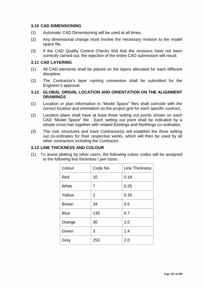
Page 197 of 289
3.10 CAD DIMENSIONING(1) Automatic CAD Dimensioning will be used at all times.(2) Any dimensional change must involve the necessary revision to the model
space file.(3) If the CAD Quality Control Checks find that the revisions have not been
correctly carried out, the rejection of the entire CAD submission will result.3.11 CAD LAYERING(1) All CAD elements shall be placed on the layers allocated for each different
discipline.(2) The Contractor’s layer naming convention shall be submitted for the
Engineer’s approval.3.12 GLOBAL ORIGIN, LOCATION AND ORIENTATION ON THE ALIGNMENT
DRAWINGS(1) Location or plan information in “Model Space” files shall coincide with the
correct location and orientation on the project grid for each specific contract.(2) Location plans shall have at least three setting out points shown on each
CAD “Model Space” file. Each setting out point shall be indicated by asimple cross-hair together with related Eastings and Northings co-ordinates.
(3) The civil, structures and track Contractor(s) will establish the three settingout co-ordinates for their respective works, which will then be used by allother contractors including the Contractor.
3.13 LINE THICKNESS AND COLOUR(1) To assist plotting by other users, the following colour codes will be assigned
to the following line thickness / pen sizes:
Colour Code No. Line Thickness
Red 10 0.18
White 7 0.25
Yellow 2 0.35
Brown 34 0.5
Blue 130 0.7
Orange 30 1.0
Green 3 1.4
Grey 253 2.0

Page 198 of 289
3.14 CAD UTILISATION of 2D and 3D FILESAlthough the project standard is 2D CAD files, certain disciplines andcontractors may use 3D CAD files for specific applications or where theisolated use of 3D aids the design and visualisation process (i.e.architecture, survey and utilities).
3.15 CAD FILE NUMBERINGContractor’s CAD file numbering shall be as described in 2 above.

Page 199 of 289
APPENDIX 8TEMPORARY POWER SUPPLY
Page 200 of 289
1 INTRODUCTIONThe standard conditions applying to temporary power supply to any WorksArea by the Contractor for its Site facilities are given under Clause 2 of thisAppendix.
2 GENERAL(1) The Contractor shall nominate a qualified electrical supervisor, whose name
and qualifications shall be submitted in writing to the Engineer for review,who shall be solely responsible for ensuring the safety of all temporaryelectrical equipment on Site.
(2) The Contractor shall not install or operate any temporary electrical systemson the Site until this electrical engineer is appointed and has commencedduty.
(3) The name and contact telephone number of the qualified electrical engineershall be displayed at the main distribution board for the temporary electricalsupply so that he can be contacted in case of an emergency.
(4) All electrical installation work on Site shall be carried out in accordance withthe requirements laid down in the Performance Specification and Indianstandards.
(5) All work shall be supervised or executed by qualified engineers or suitablyskilled and authorised electricians.
(6) Temporary electrical Site installations and distribution systems shall be inaccordance with the rules and regulation applicable for and/or applied by:a) The local electrical company supply rules;b) Wiring regulations;c) Distribution of electricity on construction and building sites;d) Distribution assemblies for electricity supplies for construction and
building sites;e) Regulations for fire safety norms and requirements for civil works;
andf) Any other applicable Indian standards and regulations.
2.1. MATERIALS, APPLIANCES AND COMPONENTSAll materials, appliances and components used within the distributionsystem shall comply with Indian standards.
2.2. EARTHING(1) Earthing and bonding shall be provided for all electrical installations and
equipment to prevent the possibility of dangerous voltage rises and toensure that faults are rapidly cleared by installed circuit protection.
(2) Earthing systems shall conform to the following standards:a) Wiring regulations;b) Guide for safety in AC substation grounding.
Page 201 of 289
2.3. PLUGS, SOCKET OUTLETS AND COUPLERSLow voltage plugs, sockets and couplers, as well as the high voltagecouplers and 'T' connections shall be colour coded in accordance with, andconform to Indian Standards.
2.4. LIGHTING INSTALLATION(1) Where Site works are required during the night, the lighting circuits shall be
run separate from other sub-circuits and shall be in accordance with IndianStandards.
(2) Voltage shall not exceed 55V to earth except when the supply is to a fixedpoint and where the lighting fixture is fixed in position.
(3) Luminaries shall have a degree of protection not less than IP 54.(4) In particularly onerous environments where the luminaries are exposed to
excesses of dust and water, a degree of protection to IP 65 shall beemployed.
(5) The Contractor shall provide a minimum lighting level of 200 lux by localisedlighting in all areas where required for carrying out the works.
(6) Wherever a risk of damage may occur, luminaries shall be mechanicallyprotected against impact damage by use of wire guards or other suchdevices.
2.5. ELECTRIC MOTORS(1) Totally enclosed fan cooled motors to Indian Standards shall be used.(2) Motor control and protection circuits shall be as stipulated in Indian
Standards.(3) Emergency stop switches shall be provided for all machinery.2.6. INSPECTION AND TESTING
Electrical installations on Site shall be inspected and tested in accordancewith the requirements of the wiring regulations.
2.7. IDENTIFICATIONIdentification labels shall be affixed to all electrical switches, circuit breakersand motors to specify their purpose.
2.8. MAINTENANCE(1) Regular maintenance and checking of control apparatus and wiring
distribution systems shall be carried out by a engineer or electrician (dulyqualified to carry out the said checks) to ensure safe and efficient operationof the systems.
(2) All portable electrical appliances shall be permanently numbered (scarf taglabels or similar) and a record kept of the date of issue, date of the lastinspection and the recommended inspection period.

Page 202 of 289
APPENDIX 9 :PROJECT CALENDAR
Page 203 of 289
1. The Project Calendar(1) The Project Weeks shall be commenced on a Monday.(2) A day shall be deemed to commence at 00:01 hour on the morning of the
day in question.(3) Where reference is made to the completion of an activity or Milestone by a
particular week, this shall mean by midnight on the Sunday of that week.Requirements for the computation of Key Dates are given in Paragraph 3,Part 2 “Employer’s Requirement, Section V, Volume 6, Appendix 2 –Work Areas and Contract Stages”.
(5) A 7 day week calendar shall be adopted for various (Work) programmeschedules for scheduling purposes, which shall also display the rest day andholidays.(6) For Project purposes, the presentation shall be in ‘Week”’ units.

Page 204 of 289
APPENDIX 10:FIRST AID BASE

Page 205 of 289
1. FIRST AID BASE(1) First aid bases shall be located at each of the Contractor's principal Works
Area.(2) The base shall consist of a treatment room fitted with two treatment
couches, a hand wash basin, sterilising equipment and lockable cupboardsto contain sufficient medical supplies for the Contractor's personnel, theEmployer’s personnel, the Engineer’s personnel and the interfacingcontractor working in the area and any visitors to the Site.
(3) In addition, two stretchers shall be stored, available for instant use.(4) The first aid base shall contain a recovery room that shall be furnished with
six chairs and a centre table.(5) The first aid base shall be air-conditioned. ,2. STAFFING(1) A qualified doctor shall be available on call during all times when work is
being undertaken on Site.(2) In each Site office and location at least one employee of the Contractor shall
be trained in first aid and shall be available during all working hours for thepurpose of attending to emergencies.
(3) The Contractor may have a tie-up with the local health centres where theyare unable to implement any of the above services.
3. EQUIPMENT(1) A fully equipped ambulance and driver shall be available on call during all
working hours.(2) The ambulance shall be equipped with emergency life support equipment
suitable for application in construction Site accidents.(3) Portable first aid boxes will be maintained fully equipped at each of local
Site offices and work locations where twenty (20) or more persons work at atime.

Page 206 of 289
APPENDIX 11 :DESIGN CERTIFICATE

Page 207 of 289
DESIGN CERTIFICATE
This Design Certificate refers to Submission No. ..……… which comprises:[*Design Package No. .... / the Definitive Design and Drawing SubmissionNo. .... / Technical Submission No. ....] in respect of :[description of the Works to which the submission refers]
The contents of this submission are scheduled in Section A below.The documents scheduled in Section B below, for which a Notice of NoObjection has been issued, are of relevance to this submission.
DESIGNER’S STATEMENTWe hereby certify that :
a) the design of the Works, as illustrated and described in the documentsscheduled in Section A below, complies with the specifications requirementsand ...... [see note 1 below];
b) the outline designs, design briefs and performance specifications of thoseelements of the Works as illustrated and described in the documentsscheduled in Section A below comply with the specifications requirementsand ...... [see note 1 below];
c)the design of the Works, as illustrated and described in the documentsscheduled in Section A below, complies with the Employer's Requirementsspecifications requirements and ...... [see note 1 below] except in thefollowing respects:
(i) ....... (to be completed by Contractor/Designer)(ii) ...… (etc.)
d) an in-house check has been undertaken and completed to confirm thecompleteness, adequacy and validity of the design of the Works asillustrated and described in the documents scheduled in Section A below;
e) all necessary and required approvals relating to the design of the Works, asillustrated and described in the documents scheduled in Section A below,have been obtained and copies of such approvals are annexed in Section Cbelow;AND (in the case of a submission covering a part of the Works only) :
f) all effects of the design comprising the submission on the design of adjacentor other parts of the Works have been fully taken into account in the designof those parts.
Signed by ‘Authorised Representative’(for Designer)NamePosition/ DesignationDate

Page 208 of 289
CONTRACTOR’S CERTIFICATIONThis is to certify that all design has been performed utilising the skill andcare to be expected of a professionally qualified, competent designer,experienced in work of similar nature and scope. This further certifies that allworks relating to the preparation, review, checking and certification ofdesign has been verified by us.Signed by ‘Authorised Representative’ (for Contractor)NamePosition/DesignationDateNote 1The Contractor shall insert one of the following, as applicable:
(i) the Contractor's Technical Proposals(ii) the Contractor's Technical Proposals and Design
Packages Nos. ........ for which a Notice of No Objectionhas been issued.
(iii) Design Packages Nos. ....….. for which a Notice of NoObjection has been issued if such Design Packagesdevelop and amplify the Contractor's TechnicalProposals.
(iv) The Definitive DesignSection A
Submission no. .... comprises the following :Drawings : (Title, drawing number and revision)Documents: (Title, reference number and revision)Others:
Section BDocuments for which a Notice of No Objection has been issued and whichare of relevance to this Submission No. .....Document:Submitted with[*Design Package No. ..……………/
The Contractor is required to providethis information in respect of eachdocument in Section B
Definitive Design SubmissionNo…………/Good for Construction DrawingSubmission No. ..../Technical Submission No. ..…………/Date of Issue of Notice of No Objection(* Delete as appropriate)
Section C[Contractor to attach copies of necessary and required approvals]

Page 209 of 289
APPENDIX 12 :SITE SAFETY PLAN AND ENVIRONMENTAL
PROTECTION REQUIREMENTS
Page 210 of 289
1 Site Safety Plan1.1 General(1) The Contractor shall, within sixty (60) days of the Commencement Date,
prepare and submit to the Engineer for review his proposed safety plan, aspart of the Contractor’s Safety, Health and Environment Plan, which shallcontain as a minimum items as mentioned in 1.2 to 1.13 below. .
(2) Procedures for updating the site safety plan and associated assurancesystem shall be given.
(3) The compensation for affected workers or their relatives shall be paid by theContractor in such cases utmost expeditiously in accordance with theWorkmen’s Compensation Act.
1.2 Statement of the Contractor’s Safety PolicyThe Contractor shall produce:
(1) a policy statement signed by the managing director of the Contractor or othersenior officer acceptable, to the Engineer or the managing directors or othersenior officers of each company of the joint venture comprising theContractor, declaring that the Contractor shall ensure that safety andindustrial health are given priority consideration in all aspects of the Worksby the Contractor in discharging his contractual obligations;
(2) An understanding of and means of ensuring due compliance with thestatutory regulations and standards relating to construction work in India;
(3) The statutory and contractual obligations regarding safety, rescue andindustrial health imposed on the Contractor; and the means by which theContractor will supervise, monitor and audit his site safety assurancesystem to ensure due compliance with these obligations.
1.3 Appointment, Duties and Responsibilities of Safety Staff(1) The “safety staff and organisational structure”, should identify the personnel
to be engaged solely for site safety assurance, the responsibilities of theparticipants and the subdivision of the site safety assurance tasks intoelements which can be effectively controlled, technically and managerially.
(2) Names, addresses, telephone and facsimile numbers of all participants shallbe listed where known (supplements to the site safety plan will update andcomplete this information);
(3) The powers vested in the safety staff, which shall be sufficient to enablethem to take urgent and appropriate action to make safe the site andprevent unsafe working practices or other infringements of the safety plan orstatutory regulations;
1.4 Policy for Identifying Hazards(1) The means by which the Contractor will identify hazards, assess the risks
and develop procedures and method statements to minimise the risk forthose risks which will occur during the works;
(2) The Contractor shall produce a list of safety and health hazards identified forthis Contract and the procedures and method statements for achieving

Page 211 of 289
effective and efficient minimisation of the risks associated with suchhazards;
1.5 Safety EquipmentThe means by which safety equipment, scaffolds, guard-rails, workingplatforms, hoists, ladders and other means of access, lifting, lighting, signingand guarding equipment shall be inspected, tested and maintained and thestandards below which such items will be removed from the site andreplaced shall be elaborated.
1.6 Contractor’s Equipment(1) The Contractor shall produce policy and procedures for ensuring that all his
plant and equipment used on the works site is maintained in a safe conditionand is operated in a safe manner;
(2) Also regulations and procedures covering all safety and health aspects ofthe Works, including where appropriate but not limited to the following shallbe produced by the Contractor:a) housekeepingb) working on or near operating railwaysc) fire prevention precautions and fire fighting equipmentd) hot weather workinge) electrical equipmentf) welding/cutting operations and equipmentg) personal protection clothing and equipmenth) cranesi) hoistsj) other lifting appliancesk) manual liftingl) power toolsm) hand tools and portable power driven toolsn) hazardous substanceso) working at heightp) structural steel erectionq) lightingr) protection against falling objects;s) working in confined placest) excavationu) Conveyance, Handling & Use of explosivesv) Scaffolding & work Platformsw) Working at heightx) Protection against falling objects
1.7 Sub-Contractors(1) The means by which safety, rescue and industrial health matters and
requirements will be communicated to sub-Contractors of all tiers and their
Page 212 of 289
due compliance with the site safety plan and all relevant statutoryregulations is ensured by the main Contractor.
1.8 Disciplinary Procedures(1) The Contractor’s disciplinary procedures with respect to dealing with safety
related matters both with his own staff and that of sub-Contractors shall begiven.
1.9 Accident Reporting(1) The Contractor’s procedure for reporting and investigating accidents,
dangerous occurrences or occupational illness;
1.10 Safety Promotion(1) The Contractor shall provide details of the frequency, coverage and intent of
site safety meetings together with the rationale for attendance.1.11 Site Security(1) The Contractor’s system for the protection of authorised and unauthorised
visitors to the site;(2) The Contractor’s proposals to ensure that construction methods do not
compromise the Contractor's commitment to the site safety plan or itscompliance with the statutory regulations.
1.12 Labour Safety(1) The activities of Contractor shall be co-ordinated with Indian Railways so as
to ensure safety of all Contractor’s personnel.(2) Labour safety arrangements by the Contractor shall be in accordance with
the applicable legislation in India.(3) The design and construction shall comply with the applicable legislation in
India.(4) The Contractor shall provide the equipment needed for the labour safety
during the operation of the line.1.13 Site Safety Plan
The brief outline of site safety plan shall cover the following:
1.13.1 Safety Personnel(1) The Contractor shall appoint a safety officer whose duties throughout the
period of the Contract shall be entirely connected with the safety andindustrial health aspects of the Contractor's activities on the site.
(2) The Contractor shall ensure that the safety officer maintains a daily site safetydiary, such diary comprehensively recording all relevant matters concerningsite safety, safety inspections and audits, safety related incidents and thelike.
(3) The site safety diary shall be reviewed and signed on a weekly basis by theContractor’s site representative and shall be available at all times forinspection by the Engineer.
Page 213 of 289
1.13.2 - Site Safety Inspections(1) The Contractor will conduct site safety inspections at a regular frequency.(2) The findings of the inspections shall be recorded on suitable forms which
shall be kept available for inspection by the Engineer.1.13.3 Safety / Accident Reporting(1) The Contractor shall submit regular site safety reports to the Engineer in
accordance with the site safety plan.(2) Such reports shall be submitted as part of the Monthly Progress Report. Prior
to submission, the site safety report shall be endorsed by the ProjectDirector responsible for the Contract and the Contractor’s siterepresentative.
(3) The Engineer shall be informed by the Contractor verbally immediately afteroccurrence of any accidents whether on-site or off-site in which theContractor, its personnel or plant, or those of its sub-Contractors are directlyor indirectly involved and which results in any injuries to any persons, loss /damage to plant and machinery, disruption of traffic etc. This shall befollowed by a written comprehensive report within 24 hours of the accident.
1.13.4 Sub-Contractors(1) The Contractor shall provide its sub-Contractors with copies of the site safety
plan and shall incorporate into all sub-contract documentation provisions toensure the compliance with such plan at all tiers of the sub-contracting.
1.13.5 Safety Meetings(1) The Contractor shall convene regular safety meetings in accordance with the
safety plan and shall ensure attendance by the safety officer and safetyrepresentatives of sub-Contractors unless otherwise agreed by theEngineer.
(2) All safety meetings shall be notified in advance to the Engineer who mayattend in person or by representative at his discretion.
(3) The minutes of all safety meetings shall be taken and sent to the Engineerwithin seven (7) days of the meeting.
1.13.6 Safety Equipment(1) The Contractor shall identify the safety equipment, rescue apparatus and
protective clothing which will be required for the Works.(2) The Contractor shall ensure that safety equipment and protective clothing as
described in the safety plan is available and used on the site at all materialtimes and those measures for the effective enforcement of proper utilisationand necessary replacement of such equipment and clothing is incorporatedinto the site safety plan.
(3) The Contractor shall regularly inspect, test and maintain all safety equipment,and those found damaged, dirty, incorrectly positioned or not in workingorder shall be repaired or replaced immediately.
1.13.7 First Aid(1) The Contractor shall establish, maintain, staff, and fully equip a first aid base
as detailed in Employer’s Requirement Appendix – 10.
Page 214 of 289
1.13.8 Site Publicity(1) The Contractor shall ensure that safety, rescue and industrial health matters
are given a high degree of publicity to all persons regularly or occasionallyon the site.
1.13.9 Training(1) The Contractor shall conduct regular safety training and rescue training drills,
the frequency, coverage and application of which shall be in accordancewith the site safety plan, and in any case shall not be more than every sixmonths. Engineer may monitor the content of such training programs.
1.13.10 Breach of Safety Regulations(1) Any employees of the Contractor or sub-Contractor of any tiers who commit a
serious breach of the safety regulations shall be liable to summary dismissaland shall not be re-employed on the Contract or allowed on any of the sites.
(2) The due notice of this sanction shall be prominently displayed on the site.
1.13.11 Safety Devices(1) All plant and equipment used on or around the site shall be fitted with
appropriate safety devices which shall be operational at all times and shallbe regularly inspected and tested.
1.1.13.12 Testing and Certification of Lifting Gear(1) The Contractor shall provide and maintain safe mechanical cranes, hoists
and conveying facilities for the lifting and transport of materials and shallcomply with all relevant codes of practice for safe use of cranes.
(2) All cranes, hoists and the like shall be fitted with audible overload warningdevices.
(3) All such equipment shall be regularly maintained in accordance withmanufacturers' recommendations and standards having regard to locallegislation and recommendations from the appropriate statutory authority.
1.13.13 Fire Regulations and Safety(1) The Contractor shall provide and maintain all necessary temporary fire
protection and fire fighting facilities on the site during the construction of theWorks, and shall comply with all requirements of the local fire servicesdepartment.
(2) These facilities may include, without limitation, sprinkler systems and firehose reels in temporary site buildings, raw water storage tanks and portablefire extinguishers suitable for the conditions on the site and potentialhazards.
(3) The Contractor shall submit details of these facilities to the Engineer forreview prior to commencement of work on the site.
1.13.14 Interface with Indian Railway Operations
Page 215 of 289
(1) The Contractor will review the interfaces with Indian Railway’s operationsand prepare a specific safety plan for all works that may affect the operatingrailway.
(2) The Contractor will comply with and incorporate Indian Railway’s rules andregulations for track, signalling and operations possessions into his safetyplan and will operate a permit to work system for all works which may affectthe operations of the existing railway.
(3) Similarly, the site safety plan shall consider with other interfacing contractorsin the closed vicinity of the Employer.
1.13.15 Standby Equipment(1) The Contractor shall provide adequate stand-by equipment to ensure the
safety of personnel, the Works and the public.1.13.16 Co-operation(1) The Contractor shall provide full co-operation and assistance in all safety
surveillance carried out by the Engineer or the Employer. Any breaches ofthe site safety plan or the statutory regulations or others disregard for thesafety of any persons may be the reason for the Engineer to exercise hisauthority to require the Contractor’s site representative’s removal from thesite. Besides this Engineer may impose token penalty for such lapses asconsidered fit.
2 Environmental Protection Requirements2.1 Measures for the Mitigation of Environmental Impacts
This section describes mitigation measures to be taken in pre-constructionconstruction and defect notification stages against environmental impacts.While compliance of applicable statutory laws is essential, mitigationmeasures as described herein are to be adopted.
2.2 General(1) The Contractor shall develop within sixty 60 days of the Commencement
Date its own Environment Management Plan (EMP), as part of theContractor’s Safety Health and Environment Plan (SHE), and submit to theEngineer for approval in accordance with, relevant Government of IndiaLegislation like Pollution Control Board, various environmental monitoringagencies of Government etc.
(2) The Contractor’s detailed technical designs for the Works and operationsduring construction shall conform to Indian Environmental Laws.
(3) The current national standards established by the Indian Government forcontrol of environmental pollutants such as air, water, noise and visualimpacts/aesthetics shall be followed for compliance during pre-construction,construction and defect notification stages, .
(4) The Contractor shall ensure that proper and adequate provisions to this endare included in all sub-contracts placed by him.
(5) The provisions mentioned here however, shall not be applicable in the caseof emergency works necessary for saving of life and property or safety ofthe Works which shall have prior approval of Engineer in all cases.
Page 216 of 289
(6) The Contractor shall undertake environmental monitoring as required underthe contract,.
(7) The Contractor shall prepare a plan for self-monitoring over the course ofthe project and submit to the Engineer for approval.
(8) The Contractor shall ensure that audits of all the activities detailed in hisEMP are carried out at monthly intervals and reported in the MonthlyReports to ensure the continuing effectiveness and compliance with theEMP.
(9) The Contractor shall make available on request any document, whichrelates to his recent internal audits.
(10) The Engineer may conduct quarterly audits of the Contractor’s EMP and itseffective implementation on the works site.
(11) During the audit the Contractor shall provide a suitable number of qualifiedstaff as directed as directed by the Engineer to assist the Engineer duringthe audit.
(12) Requirements established in the EMP specification shall apply to all sitesand all activities of the Contractor, including the detailed technical designs ofthe civil infrastructure, and shall supplement the Employer’s Requirements.
(13) In the EMP the Contractor shall appoint a suitably qualified managerresponsible for the environmental as well as a support team to assist thismanager. Roles and responsibilities and key communication links must behighlighted to ensure responsibility for implementing the EMP.
(14) The Contractor shall ensure that its Environment Plan documentationincludes but is not limited to the provisions covered in the SHErequirements.
2.3 Environmental Management ProcessEnvironmental management is based on the potential impacts assessed forthe project. Assessment of potential impacts is based on the review ofsecondary data substantiated by site visits – environmental monitoring,public consultation, household survey and discussion with concerned Govt.Dept. The implementation of Environmental Management Plan (EMP)requires the following:-
a) An organizational structureb) Assign responsibilitiesc) Define timing of implementationd) Define monitoring responsibilities
2.4 EMP during ConstructionThe project activities shall be executed in a phased manner, pre-construction phase, construction phase and operation phase. The majoractivities to be undertaken during construction phase are described below.The environmental issues during construction phase generally involvequality, safety and public health issues. The Contractor is required to complywith the laws with respect to environment protection, pollution control, forestconservation, safety and any other applicable laws. Environmental pollutioncontrol during the construction phase shall be the responsibility of theContractor. EMP is an executable part of project and the activities are to beguided, controlled, monitored and managed as per the provisions provided.

Page 217 of 289
2.5 Land Acquisition / Diversion PlanAcquisition of land for ROW is the responsibility of DFCCIL. The proposedalignment is not passing through any forest area.
i. The acquisition of land and private property shall be carried out in accordancewith prevailing rules.
ii Where temporary land is acquired by the Contractor for setting up labourcamp, work site, placing of construction related equipment, dumping ofwastes, stacking of excavated earth, construction materials etc., theContractor shall be responsible for such land acquisition/ hiring from therightful owners following applicable procedures/ rules, compensation / rentthereof.
2.6 Avoidance of Nuisance
a) The Contractor shall take all precautions to avoid any nuisance arising fromhis operations. This shall be accomplished, wherever possible bysuppression of nuisance at source rather than abatement of the nuisanceonce generated.
b) Following site clearing and before construction, the Contractor shall removeall trash, debris and other weeds.
c) The Contractor shall ensure that the work place is free of trash, garbage,debris and weeds. He shall provide and ensure proper uses of refusecontainers to ensure that rodents, insects and other pests are not harbouredand attracted.
d) The Contractor shall provide a dedicated team of workers at each work sitewho shall be solely employed to keep the site and its surroundings in aclean condition and maintain a good standard of house-keeping on the site.
e) The Contractor shall promptly transport all excavation disposal materials ofwhatever kind so as not to delay work on the project. Stockpiling ofmaterials shall only be allowed at sites designated by the Engineer.
f) The Contractor’s temporary dumping areas shall be maintained by theContractor till the materials are re-utilized for back-filling or any otherpurpose as per instruction of Engineer.
2.7 Utility Shifting
This shall be dealt as per provision in Appendix 1 (Utilities) and otherprovisions of Bid Documents.
2.8 Construction / Labour Camp ManagementDuring the construction phase, proper construction camp development planhas to be formulated to control degradation of the surrounding landscapedue to the location of the proposed construction camp. The Contractor mustprovide, construct and maintain necessary living condition and ancillaryfacilities which shall include:
a) Sufficient supply of potable water must be provided at camps and workingsites. If the drinking water is obtained from the intermittent public watersupply, then storage tanks must be provided. All water supply storage maybe sufficiently away from the toilets or drains.
Page 218 of 289
b) Adequate and clean washing and bathing facilities must be provided thatalso have sufficient drainage.
c) Adequate sanitary facilities may be provided within every camp. The placemust be cleaned daily and maintain strict sanitary conditions. Separatelatrine must be provided for women. Adequate supply of water must also beprovided.
d) The contactor must ensure that there is proper drainage system to avoidcreation of stagnant water bodies.
e) No open fires may be allowed in camps.f) The sites should be secured by fencing and proper lighting.g) The construction contractor may ensure that all construction equipments
and vehicle machinery may be stored at a separate place / yard.h) Fuel storage and refilling areas may be located 500 m away from the water
bodies and from other cross drainage structures.i) All the construction workers should be provided with proper training to
handle potential occupation hazards and on safety and health which includethe following:- Environmental awareness program Medical surveillance Engineering controls, work practices and protective equipment Handling of raw and processed material Emergency response
j) Construction / labour camps shall be located away from forest areas,settlements, cultural heritage and historical sites and water bodies and dryriver beds.
k) It should be ensured by the construction contractor that the camp area iscleared of the debris and other wastes after the completion of construction.On completion of construction, the land should be restored back to itsoriginal form to the satisfaction of DFCCIL.
2.9 Mitigation Measures of Land Environment during Construction
While DFCCIL is responsible for land acquisition for clear ROW, theContractor shall be responsible for use of the land during construction.Hence, the Contractor shall take necessary measures as enumerated in theEMP to prevent/ arrest soil erosion, contamination.
2.10 Borrow Area Management Plan
Borrow areas shall be identified and finalized by the Contractor inconsultation with Engineer. Formal agreement between landowners and theContractor has to be made. Suitability of burrow areas from civil Engineeringas well as environmental consideration have to be ensured. Meeting theguidelines/notifications as stipulated from time to time by the Ministry ofEnvironment and Forests, Government of India, and local bodies, asapplicable shall be the sole responsibility of the Contractor.Besides this, precautions are to be taken by the Contractor for nounauthorized borrowing. No borrow area shall be opened without permissionof the Engineer. Engineer in addition to the established practices, rules andregulation shall also consider under-mentioned criteria before approving the
Page 219 of 289
Borrow areas.To avoid any embankment slippage, the borrow areas shall not be dugcontinuously and the size and shape of borrow pits shall be decided by theEngineer.To ensure that the spills, which might result from the transport of borrow andquarry materials do not impact the settlements, it shall be ensured that theexcavation and carrying of earth shall be done in a careful manner. Theunpaved surfaces used for the haulage of borrow materials shall bemaintained properly. Contractor shall ensure the following issues arecovered to the satisfaction of Engineer.
a) Water pooling to be avoided/managed so that no disease spread ormosquito breeding takes place due to water stagnation.
b) Precautionary measures as the covering of vehicles may be taken to avoidspillage during transportation of borrow area.
c) Haulage of material to embankments or other areas of fill shall proceed onlywhen sufficient spreading and compaction facility is operating at the place ofdeposition, to minimize dust pollution.
d) During rains appropriate measures to be taken to minimize soil erosion, siltfencing to be provided as directed by Engineer/EO.
e) Burrow pit should have proper guard to prevent accidental falling of childrenor animals.An appropriate Borrow Area Management Plan shall be formulated tocontrol the degradation of the surrounding landscape due to the excavationwork. The national standard which applies to the manual borrowing of earthis detailed in IRC-10:1961.
2.11 Mitigation Measures to Minimize Soil Erosion during construction
a) Suitable protection measures consisting of bio-Engineering techniques suchas plantation of grass and shrubs, may be provided to control erosion. Themeasures shall be applied along the slopes at high embankment wherebridges shall be constructed.
b) Borrow areas may be finalized in concern with ecological sensitivity of thearea. Agriculture land may not be used as borrow areas. Priority may begiven to degraded area for excavation of borrows material.
2.12 Geo-technical issues
The Contractor shall submit within the EMP the expected constructionimpacts for all major facilities and sections of higher embankments anddeeper excavations, including materials used for the building of theformation prior to construction, these impacts should include:
a) Determination of formation material quality and placement impact;b) Stability factors, including seismic migration;c) Drainage facilities for groundwater dewatering;d) Effects on the local communities and transportation networks from
overland truck transport of fill and excavate to and from the specificborrow and fill sites.
e) Specific mitigation measures and maintenance-of-traffic plans to ensureminimal disruption on local traffic conditions and the environment.

Page 220 of 289
2.13 Mitigation Measures for Ambient Air Quality
1. Pre Construction / preparatory Phase: The dust generation due to pre-construction activities shall be temporary in nature and localized and shallbe effectively countered by sprinkling of water wherever required.
2. Construction Phase: Contractor shall undertake following specific measuresregarding this aspect:-:
a) Locating plant at a significant distance from nearest human settlement in thepredominant down wind direction.
b) Vehicles delivering fine materials like soil and fine aggregates may becovered to reduce spills on existing roads.
c) Water shall be sprayed on earthworks, temporary haulage and diversions ona regular basis.
d) Pollution control systems like water sprinkling and dust extractors and coveron conveyors shall be installed for the crushers.
e) All vehicles, equipment and machinery used for construction shall beregularly maintained to ensure that the emission levels conform to theSPCB/CPCB norms.
2.14 Mitigation Measures for Water Quality
2.14.1 Water Quality ManagementContractor shall undertake following measures to avoid contamination ofwater bodies:-.
a) The discharge standards promulgated under the Environmental ProtectionAct, 1986 shall be strictly adhered to. All wastes arising from the projectshall be disposed off in a manner that are as per the provisions of the StatePollution Control Board (SPCB).
b) Water quality shall be monitored regularly near the construction site.
2.15 Sensitive Receptors – Mitigation Measures
All schools, hospitals and cultural properties and heritage sites that are.within 100 m distance of the project area require noise control measures.
2.16 Mitigation Measures for Noise during Construction Phase
a) Machinery and vehicles shall be maintained regularly, with particular attentionto silencers and mufflers, to keep construction noise levels to minimum.
b) Workers in the vicinity of high noise levels shall be provided earplugs/earmufflers helmets and shall be engaged in diversified activities to preventprolonged exposure to noise levels of more than 90dB(A) per 8 hour shift.CPCB standard is to be observed.
c) During construction vibratory compactors will be used with due care within theurban areas.
2.17 Control requirements
Under the Contract, the Contractor shall:
Page 221 of 289
a) Perform work within the procedures outlined herein and comply withapplicable codes, regulations, and standards established by the IndianGovernment and their agencies.
b) Schedule and conduct operations in a manner that shall minimize, to thegreatest extent feasible, the disturbance to the public in areas adjacent tothe construction activities and to occupants of buildings in the vicinity of theconstruction activities.
c) Submit to the Engineer a Noise Monitoring and Control Plan (NMCP), within 3months from Commencement Date, which shall form part of the overallEMP, including full and comprehensive details of all powered mechanicalequipment, which he proposes to use during daytime and night-time and ofhis proposed working methods and noise level reduction measures.
d) The NMCP prepared by the Contractor shall guide the implementation ofconstruction activity.
e) The NMCP will be reviewed on a regular basis and updated as necessary toensure that current construction activities are addressed.
f) It shall appear as a regular agenda item in project coordination meetings
2.18 Mitigation Measures for Hydrological Condition (Rivers and Lakes)
1) Construction Phase -a) To avoid any unwanted accumulation of water/ water logging, provision of
temporary drainage arrangement due to construction activities shall bemade by Contractor.
b) Silt fencing may be provided near water bodies.c) Proper drainage may be planned in the area to avoid water logging.2) Implementation Phase -
Cross drainage structures shall be provided at appropriate locationswherever local drainage is likely to be affected.
2.19 Mitigation Measures for Flora and Fauna during Construction
a) For temporary land / site hired/ acquired by the Contractor for constructionlabour camp, materials stacking/ storage, operating equipment etc. cuttingof trees will be the responsibility of the Contractor. The Contractor shallfollow all procedures as per Forest Department and / or statutory law/guidelines including compensation.
b) Labour camps and office site shall be located outside and away from theforest area.
2.20 LandscapeLandscaping plan may be formulated for restoration, leveling andlandscaping of the area once construction activities are over. This caninvolve the following:-
a) The stockpiles may be designed such that the slope does not exceed 1:2(vertical to horizontal) and the height of the pile to be restricted to 2 m.
b) Stockpiled topsoil may be used to cover the disturbed areas and cut slopes.The top soil shall be utilized for redevelopment of borrow areas, landscapingalong slopes, incidental spaces etc.

Page 222 of 289
2.21 Vibration level limita) The vibration level limits adjacent to the alignment shall conform to
appropriate legislation of Government of India in this regard.b) The scheme for monitoring the vibration level at the site shall be submitted to
Engineer for his approval.
2.22 Public Health and SafetyThe Contractor is required to comply with all the precautions required for thesafety of the workmen. The Contractor must comply with all regulationregarding scaffolding, ladders, working platform, excavation, etc.
2.23 Waste
2.23.1 Control of waste generation during construction and its safe disposal isthe responsibility of the Contractor.
a) Principle of 3R’s (Reduce, Reuse, Recycle) shall be followed while handlingwaste from the construction Site. The Contractor is required to develop,institute and maintain a Waste Management Programme (WMP) during theconstruction of the project for his works, which may include:-i. Identification of disposal sites.ii. Identification of quantities to be excavated and disposed off.iii. Identification of split between waste and inert materialiv. Identification of amounts intended to be stored temporarily on site
location of such storage.v. Identification of intended transport means and route.vi. Obtaining permission, wherever required, for disposal.
b) A mechanism shall be developed to ensure that the pre-designated area isavailable for the segregation and temporary storage of reusable andrecyclable materials. This shall be incorporated in the WMP. The WMPshould be prepared and submitted to the Engineeer for approval.
c) The Contractor shall handle waste in a manner that ensures that wastes areheld securely, maintained and waste storage area is cleaned regularly.
d) The Contractor shall remove waste at regular interval and dispose at landfillsites, if available nearby, after obtaining approval/ consent of concernedauthority. If such authority or landfill site is not available nearby, the wastesmay be dumped at a pre-designated site within Project area in consultationwith Engineeer.
e) The Contractor shall not burn debris or vegetation or construction waste onthe site but remove as per relevant Rules.
f) The Contractor shall make arrangements to disposal off metal scrap andother wastes which can be sold to authorized dealer(s) and maintain recordof such sale for inspection by the Engineeer.
2.23.2 Hazardous Waste Management (by Contractor)1) Any waste classified as hazardous under the “Hazardous Wastes
(Management, Handling and Transboundary) Rules, 2008, shall bedisposed according to the concerned Rules.

Page 223 of 289
2) Chemicals classified as hazardous chemicals under “Manufacture, Storageand Import of Hazardous Chemical Rules, 1989 shall be stored incompliance with the said Rules.
3) Outside the storage area, the Contractor shall place a display board clearlymentioning ‘Hazardous Wastes’ and quantity and nature of wastes, on date.Hazardous Waste needs to be stored in secured manner..
4) It shall be the responsibility of the Contractor to ensure that hazardouswastes are stored, based on the composition, in a manner suitable forhandling, storage and transport. The labeling and packaging is required tobe easily visible and be able to withstand physical conditions and climaticfactors.
5) The Contractor shall approach only registered & authorized Recyclers ofHazardous Waste for direct sale/ disposal of Hazardous Waste..
**

Page 224 of 289
APPENDIX 13 :TRAFFICE BLOCK (POSSESSION) MANAGEMENT

Page 225 of 289
1. GENERAL(1) The Contractor shall comply with the traffic block (Possession) management
system operated by Indian Railways (IR).(2) The Contractor shall appoint a responsible person who shall coordinate with IR
and with the other adjacent civil, structures and track works contractors and thesystems contractor as applicable and who will act as the traffic block coordinatorfor the Contractor only.
(3) The person appointed must have experience of IR operations and must be fullyaware of IR rules and regulations related to possession of track for constructionof railway works and in accordance with IR regulations to issue possessionrequests.
(4) For the purpose he shall be duly certified in accordance with the said rules.
2. POSSESSION PERIODS(1) The Contractor may use possessions on the line for execution of works as per
approved plan following strict safety procedures.(2) Line closures may be agreed subject to IR approval.(3) The Employer gives no warranty that line closures and possession periods will be
available during the period of the Works.(4) The Employer will however provide any assistance necessary to the Contractor to
enable him to obtain the line closures and possessions required by him for theWorks but will not be responsible if any Possession requests are refused by IR.
(5) The Contractor shall prepare technological and organizational schedule forconstruction which shall include the work times in the weekends and during thedark part of the day.
(6) The Contractor shall submit his requests for ‘possessions’ at least fourteen (14)days earlier and inform IR at least 48 hours earlier if he is not able to use thepermitted ‘possessions’.
(7) Any fees which may become leviable on account of track possessions required bythe Contractor for permanent or temporary works shall not be payble by theContractor. However penalities, if any, levied by Indian Railways caused due toany careless working or otherwise of violation of the Terms and Conditions of thetrack possessions, shall be payable by the Contractor.
***

Page 226 of 289
APPENDIX 14 :DESIGN STANDARDS

Page 227 of 289
Following is the indicative list of Design standards. All codes and manuals withcorrection slips issued upto 28 days prior to last date of submission of bid shall beapplicable for this bid. Any other applicable code, circular, instruction of UIC to bereferred with the approval of the Engineer.”In case of any contradiction in the various codal provisions, the order of precedenceshall be as follows:
a) Specific provisions in Part-2- Employers Requirement.b) IRS Codal provisionsc) IRC Codal Provisionsd) IS/BIS Codal provisionse) Provisions in the other foreign codes.However in case of road related structures, IRC codal provisions shall prevailover IRS codal provisions.
Earthworksa) IS:2720 Part 2 Determination of water content.b) IS:2720 Part-4 Grain size analysis.c) IS:2720 Part-5 Determination of liquid and plastic limits.d) IS:2720 Part-8 Determination of water content – dry density relation using
heavy compaction.e) IS:2720 Part-16 Laboratory determination of CBR.f) Ministry of Railways Guidelines And specifications-Design of Formation for
Heavy Axle Load-Report No: RDSO/2007/GE:14g) Ministry of Road Transport and Highways Specification for Bridge Works, 4th
edition.h) Report on “Guidelines for Use Of Geosynthetics On Railway Formation
Including Specifications” (Provisional) Report No. RDSO/2007/GE:G-0009(D) July 2008
i) Concept And Design Of Reinforced Earth Structures Report No. GE: R – 73June – 2005
j) Ministry of Railways, Guidelines for Earthwork in Railway Projects, GuidelineNo GE:G-1.
Civil Structuresa) DFC Loading Standards.b) IR Bridge Rules.c) IR Code of Practice for the Design of Substructures and Foundation of Bridge
(Bridge Substructure and Foundation Code).d) IR Manual of Design and construction of Pile and Well Foundations.
Page 228 of 289
e) IR Code of Practice for Plain and Reinforced Concrete Bridge Construction(Concrete Bridge Code).
f) BS 5400 for Bearings of Bridgesg) DFC Schedule of Dimensions for Eastern Corridor.h) Indian Railway Schedule of Dimensions:- to be consulted with the approval of
Engineer where provisions in DFC schedule of dimensions do not coverthe particular situation.
i) IR Steel Bridge Code.j) IS: 2062-2006 – Structural steelk) IR Welded Bridge Codel) Guidelines on Fabrication of Steel Griders for Construction….. (BS-110).m) IR Standard Specification for Fabrication and Erection …(B-1:2001).n) Indian Railway Works Manual.o) Indian Railway Bridge Manual.p) IS 456- Code of Practice for Plain and Reinforced Concrete.q) IS 2911 (all Parts) Code of Practice for Design and Construction of Pile
Foundations.r) IS 1493- Design of Bored and Cast in Situ Piles Founded in Rock- Guide
lines.s) IS 1893- Indian Seismic Codet) IS 1343 – Code of Practice for Pre-stressed Concrete.u) IRC 5: Standard Specifications and code of practices for Road Bridges
Section I – General features of design.v) IRC 6: Standard Specifications and code of practices for Road Bridges
Section II – Loads and stresses.w) IRC 18: Design Criteria for Prestress Concrete Road Bridges (Post-tensioned
concrete).x) IRC 21: Standard Specifications and code of practices for Road Bridges
Section III – Cement Concrete (Plain and reinforced).y) IRC 22: Standard Specifications and code of practices for Road Bridges
Section VI – Composite construction.z) IRC 78: Standard Specifications and code of practices for Road Bridges
Section VII – Foundation and Substructure.aa) IRC 83 Bearing Design.bb) UIC 772/R- Specifications for Neoprene Bearings.cc) UIC 774-3R- Track / Bridge Interaction.dd) Code of practice for Readymix concrete – IS 4926ee) IIT Kanpur-RDSO Guidelines on Seismic Design of Railway Bridges.
Page 229 of 289
ff) MMD of eastern DFC.
Tracka) Indian Railway Permanent Way Manual.b) Manual of Instructions on LWRs of IR.c) IRS GE 1 June 2004 Ballast specification.Fire Standardsa) IS 1641: 1988 Code of practice for fire safety of buildings (general) : General
principles of fire grading and classification (first revision).b) IS 3844: 1989 Code of practice for installation and maintenance of internal
fire hydrants and hose reels on premises (first revision).c) IS 1646: 1997 Code of practice for the safety of buildings (general) :
Electrical installations (second revision).d) IS 11360: 1985 Specification for smoke detectors for use in automatic
electrical fire alarm system.e) IS 1644: 1988 Code of practice for fire safety of buildings (general) : Exit
requirements and personal hazard (first revision).f) IS 2175: 1988 Specification for heat sensitive fire detectors for use in
automatic fire alarm system (second revision).g) IS 11360: 1985 Specification for smoke detectors for use in automatic
electrical fire alarm system.h) IS 2189: 1999 Code of practice for selection, installation and maintenance of
automatic fire detection and alarm system (second revision).i) IS 884: 1985 Specification for first-aid hose reel for fire fighting (first revision).j) IS 940: 1989 Specification for portable fire extinguisher, water type (gas
cartridge) (third revision).k) IS 2878: 1986 Specification for fire extinguisher, carbon-dioxide type
(portable and trolley mounted) (second revision).l) IS 11833: 1986 Specification for dry powder fire extinguisher for metal fires.Electricity Standardsa) Power supply installations and other electric installations shall comply with
Indian Electricity Standards.b) Internal wiring of buildings shall comply with Indian Building code of practice.c) All electrical installations shall be earthed as per relevant Indian standard
code for earthing of electric installations.d) In station buildings electric fittings and electric gadgets shall be provided as
per Indian Railways Boards letter No. 99/Electric/(G)/136/1 dated17.03.2006.

Page 230 of 289
e) Deviations if any to improve performance standards shall be with theapproval of Engineer.
f) Regulations for Power line Crossings of Railway tracks as per IndianRailways Manual of AC Traction
Additional Codes and StandardsThe following Indian Codes and Standards shall be referred to whereapplicable: The Energy Conservation Act, 2001 Guidelines on Equipment issued by the Bureau of Energy Efficiency Energy Conservation Building Code IR General and Subsidiary rules IR Safety Rules Relevant pollution control codes Applicable labour laws like Workmen’s Compensation Act etc.
***

Page 231 of 289
APPENDIX 15 :ENGINEER’S ACCOMMODATION
Page 232 of 289
1.0 GENERAL1.1 Site Office Requirements
The Contractor shall design, construct, equip or provide and furnish thesite offices for the Employer's and Engineer's use within 90 days afterthe commencement date. The Contractor shall also maintain the siteoffices in good conditions and provide services including, but not limited tomaintenance of the office equipment and furniture, repairing and mending,cleaning, consumable replenishment in respect of toiletries, cartridges forthe plotter and colour laser writers, first aid box, batteries / battery cells,drinking water etc. Design of all the Site Offices shall be submitted to theEngineer for review prior to commencement of the construction of thosefacilities. Details of the Engineer’s site office including provisional siteoffices are described in the following paragraphs.
All furniture, furnishings, fittings & fixture and equipment etc. shall be of theconfiguration, make and quality as consented by the Engineer.
Contractor can also provide the site office by hiring an existing buildingsubjected to the requirement of the area specified in 1.2 (3) below with theapproval of Engineer.
1.2 Engineer’s Site Offices
(1) The area surrounding the office shall be well drained and providedwith concreted pavements, walkways and parking areas for thevehicles.
(2) The main office buildings shall be of sound design and of the materialas approved by the Engineer, complying with national building codes.The office shall be weatherproof, lined inside with plywood, and paintedinternally and externally. Floors shall be tiled and floor to ceiling heightshall be as approved by the Engineer. Each room having an internalwall shall have at least one screened window. The office building shallhave two external lockable doors with screened storm doors.Electricity supply and receptacles shall be provided in various locationsappropriate to the usage of the rooms. Rooms shall be well lighted,appropriate HVAC systems with temperature control and othernecessary building services as described in the National Building Codeof India.
(3) Site office shall be provided for Engineer/Employer. The location of siteoffice will be decided with the approval of Engineer.
Engineer’s Site Offices shall be furnished as referred to the followingparameters and the design shall be submitted to the Engineer forreview.
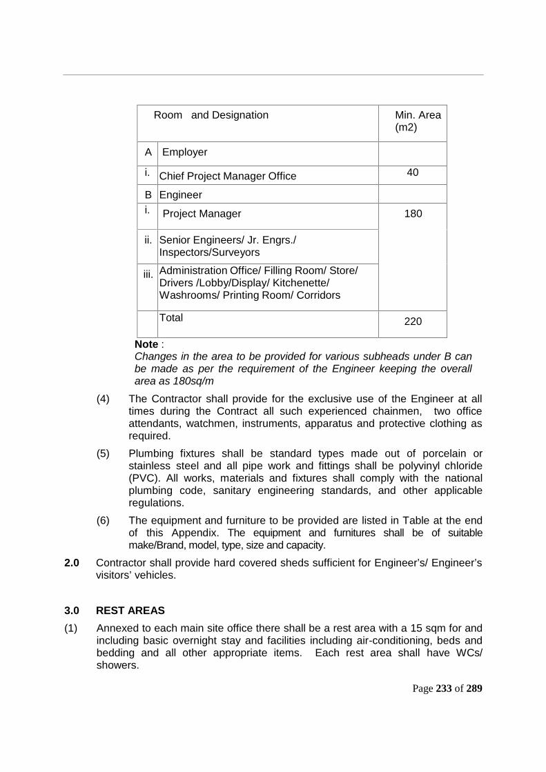
Page 233 of 289
Room and Designation Min. Area(m2)
A Employer
i. Chief Project Manager Office 40
B2.
Engineeri. Project Manager 180
ii. Senior Engineers/ Jr. Engrs./Inspectors/Surveyors
iii. Administration Office/ Filling Room/ Store/Drivers /Lobby/Display/ Kitchenette/Washrooms/ Printing Room/ Corridors
Total 220
Note :Changes in the area to be provided for various subheads under B canbe made as per the requirement of the Engineer keeping the overallarea as 180sq/m
(4) The Contractor shall provide for the exclusive use of the Engineer at alltimes during the Contract all such experienced chainmen, two officeattendants, watchmen, instruments, apparatus and protective clothing asrequired.
(5) Plumbing fixtures shall be standard types made out of porcelain orstainless steel and all pipe work and fittings shall be polyvinyl chloride(PVC). All works, materials and fixtures shall comply with the nationalplumbing code, sanitary engineering standards, and other applicableregulations.
(6) The equipment and furniture to be provided are listed in Table at the endof this Appendix. The equipment and furnitures shall be of suitablemake/Brand, model, type, size and capacity.
2.0 Contractor shall provide hard covered sheds sufficient for Engineer’s/ Engineer’svisitors’ vehicles.
3.0 REST AREAS(1) Annexed to each main site office there shall be a rest area with a 15 sqm for and
including basic overnight stay and facilities including air-conditioning, beds andbedding and all other appropriate items. Each rest area shall have WCs/showers.

Page 234 of 289
4.0 GENERAL REQUIREMENTS(1) Materials used for the construction of the offices shall be of good quality and
finish. Materials shall be chosen such that the buildings when erected shall givegood heat and sound insulation. Both external and internal walls shall be soundproof.
(2) Windows to each room shall be of an area not less then 10% of the floor area.All windows to ground floor offices shall be fitted with burglar bars firmly attachedto the structure of the building. All windows shall be fitted with mosquito netting.All windows shall be fitted with venetian blinds.
(3) Internal doors shall be hollow core flush doors and shall be fitted with doorclosers, lever latches, mortise lock and keys.
(4) External doors shall have barrel bolts both at top and bottom of one leaf and aYale lock on the other leaf. External doors shall be of solid external quality andhung with heavy-duty hinges. All sets of keys shall be delivered to the Engineer.
(5) All buildings shall be supplied with continuous (24 hour) running potable water tothe kitchens and wash rooms. The toilets may use raw water for flushing, shall beequipped with water closets and sitting type stools and shall be adequatelyventilated. The Contractor shall also arrange for the constant and hygienicdisposal of all effluent, sewage and rubbish from the buildings. Storage tanks willbe required due to restricted water supply at most locations.
(6) All buildings shall be supplied with electricity at 220 voltage and 50 Hz that shallbe distributed to each room in accordance with the regulations. Lighting andelectrical power points shall be provided in each room. The disposition andlocation of light and power points will be as directed by the Engineer. A back upgenerator is required to be provided to meet the full power load in case of powerdisruption.
(7) Each kitchen shall be provided with worktops, a 2 drainer stainless steel doublesink, cupboards beneath the worktop and mounted on the walls, a cooker with 2gas rings and a microwave oven and a 5 cu ft. refrigerator. Tea/Coffee makingfacilities for 20 persons shall be provided. Tiling shall be provided to the wallsabove the kitchen table top.
(8) Changing and shower facilities shall be provided as follows:- Male facilities: 3 showers and 3 wash basins with 15 clothes lockers and
benching with pegs over for 6 persons.- Female facilities: 1 showers and 1 wash basins with 5 clothes lockers and
benching with pegs over for 2 persons.Each shower shall be provided with hot and cold water supply and shall be
contained in an individual cubicle with a screen or curtain to the entrance. Modestyscreens shall be provided adjacent to the entrance to all changing and showerfacilities.
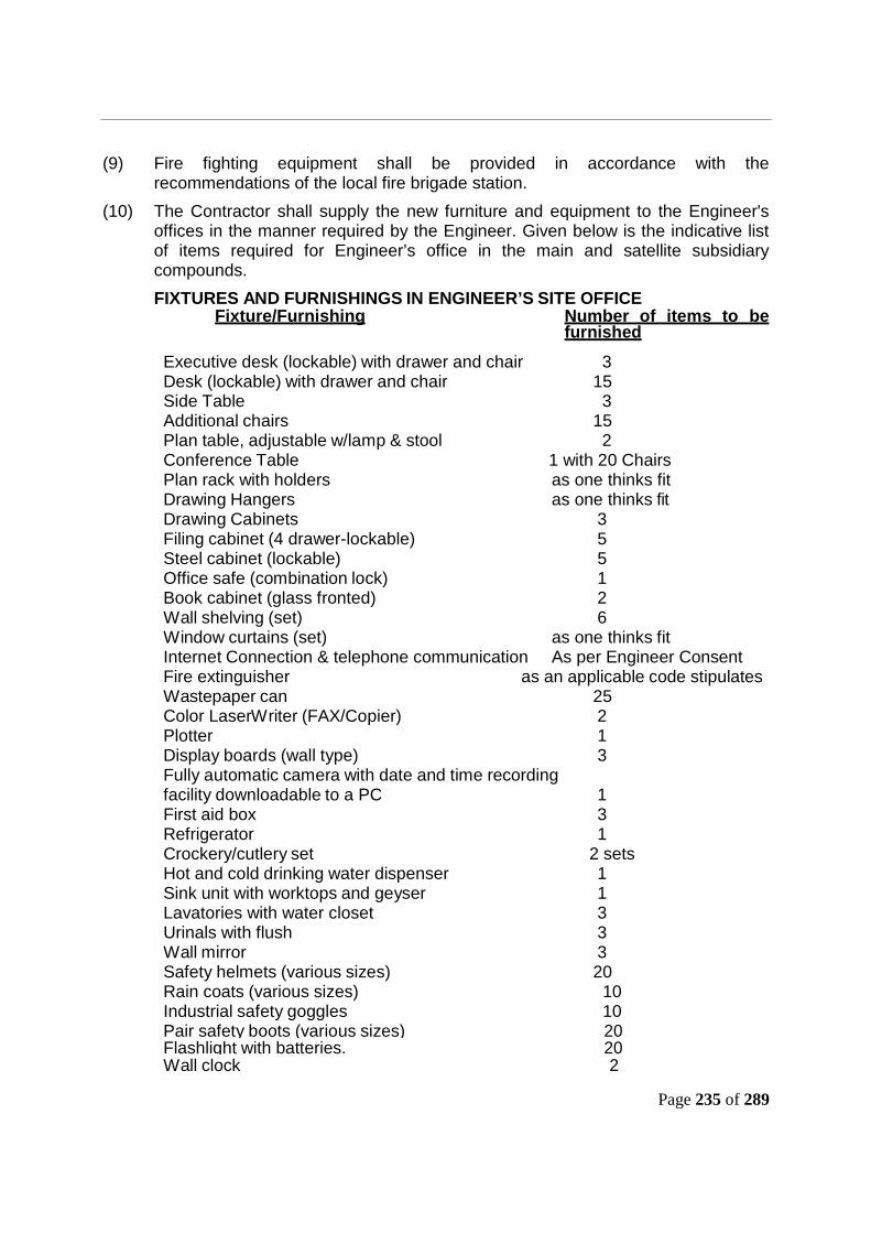
Page 235 of 289
(9) Fire fighting equipment shall be provided in accordance with therecommendations of the local fire brigade station.
(10) The Contractor shall supply the new furniture and equipment to the Engineer'soffices in the manner required by the Engineer. Given below is the indicative listof items required for Engineer’s office in the main and satellite subsidiarycompounds.FIXTURES AND FURNISHINGS IN ENGINEER’S SITE OFFICE
Fixture/Furnishing Number of items to befurnished
Executive desk (lockable) with drawer and chair 3Desk (lockable) with drawer and chair 15Side Table 3Additional chairs 15Plan table, adjustable w/lamp & stool 2Conference Table 1 with 20 ChairsPlan rack with holders as one thinks fitDrawing Hangers as one thinks fitDrawing Cabinets 3Filing cabinet (4 drawer-lockable) 5Steel cabinet (lockable) 5Office safe (combination lock) 1Book cabinet (glass fronted) 2Wall shelving (set) 6Window curtains (set) as one thinks fitInternet Connection & telephone communication As per Engineer ConsentFire extinguisher as an applicable code stipulatesWastepaper can 25Color LaserWriter (FAX/Copier) 2Plotter 1Display boards (wall type) 3Fully automatic camera with date and time recordingfacility downloadable to a PC 1First aid box 3Refrigerator 1Crockery/cutlery set 2 setsHot and cold drinking water dispenser 1Sink unit with worktops and geyser 1Lavatories with water closet 3Urinals with flush 3Wall mirror 3Safety helmets (various sizes) 20Rain coats (various sizes) 10Industrial safety goggles 10Pair safety boots (various sizes) 20Flashlight with batteries. 20Wall clock 2
Page 236 of 289
Lockers 15Safety High Glow Jackets 20Safety Harness (full body) 10
(11) Offices shall be at locations agreed by the Engineer.(12) The office accommodation shall be retained until the expiry of the Defects
Notification Period unless otherwise instructed to the contrary by the Engineer.(13) Prior to commencing the erection of the Engineer's accommodation the
Contractor shall obtain the consent of the Engineer to the accommodation,including layout, equipping, electrification plan and furnishings proposed by theContractor.
(14) The Contractor shall make such reasonable amendments to the layout andfurnishings as the Engineer may request.
(15) Unless otherwise permitted by the Engineer, the Contractor shall complete theaccommodation and provide all equipment and furnishing in sufficient time toallow the Engineer to occupy the offices prior to the commencement ofexcavation or any Permanent Works.
(16) From the Commencement Date of the Works until such time as the Engineer'soffices have been completed and accepted by the Engineer, the Contractor shallprovide such temporary offices and equipment and furnishings at such location orlocations as the Engineer may require.
(17) The accommodation shall be maintained in a clean, stable and secure conditionand shall be cleaned at least daily.
(18) Equipment provided for the use of the Engineer shall be maintained in a cleanand serviceable condition and all consumables shall be replenished whenrequired.
(19) Measuring and testing equipment shall be calibrated before they are used and atregular intervals to which the Engineer has given his consent.
(20) Survey equipment shall be maintained by the service agent and shall be regularlychecked but the overall responsibility shall rest with the Contractor.
(21) Equivalent replacements shall be provided for equipment which are not inworking order or otherwise are not in a serviceable condition or are beingrepaired or serviced.
(22) The consent of the Engineer shall be obtained before accommodation orequipments are removed.
4.1 ENGINEER'S ACCOMMODATION FOR OFF SITE WORK(1) Where any portion of the Works is prepared or fabricated off-Site or at any
fabrication facilities away from the Site, whether by the Contractor or one of hissubcontractors or suppliers, the Contractor shall provide and maintain officeaccommodation, furnishings, and equipment for the use of the Engineer and itsstaff at each such location for the duration of such work as and if required byEngineer.
Page 237 of 289
(2) The accommodation furnishings and equipment shall be suitable and sufficient forthe purposes of the Engineer and shall be according to the Engineer's consent.
4.2 Transport for the Engineer/Employer :Contractor shall provide following road transport for Employer/Engineer :
(i) Air-conditioned four wheeled vehicle of a type and colour approved byEngineer/Employer and having no trade name displayed except the name ofthe Manufacturer of the vehicle. The vehicle shall have an engine capacity ofatleast 1800 cc and have at least 4 seats -for a total period of sixty (60) vehiclemonths.
(ii) The vehicles shall be new and delivered and maintained by the Contractor ingood roadworthy condition. The vehicle shall be replaced with a new vehicleafter a maximum run of 100,000 km or five years, whichever is earlier.
(iii) The vehicles shall be licensed and insured for use on the public highway andshall have comprehensive insurance cover for any qualified driver authorised bythe Engineer together with any authorised passengers and the carriage of goodsor samples.
(iv) The Contractor shall provide fuel, oil and maintenance in conformity with thevehicle manufacturer's recommendations and all relevant toll and parkingcharges incurred in connection with the Works. The vehicles provided under thisContract are likely to log an average of 4,500 km and 350 hours/per month (theaverage will be worked out considering all the vehicles provided by theContractor and operated over a period of six months).
(v) The vehicles shall be provided by the Contractor for use of theEngineer/Employer during the day or night as required by theEngineer/Employer.
(vi) The Contractor shall organize daily cleaning of the vehicles from inside andoutside as required during the currency of the Contract.
(vii) In case of any defect requiring major repairs and grounding of the vehicle formore than 24 hours, a suitable replacement shall be provided by the Contractorfor such vehicle. In case the Contractor fails to provide vehicle(s) or substitutevehicle(s) [In case of grounding of vehicle for over 24 hours] the same shall bearranged by the Engineer/Employer from other source. An amount of Rs. 3,000per day for each vehicle (that the Contractor has failed to provide) shall berecovered from the Contractor.
(viii) The Contractor shall employ and make available competent drivers fully licensedto operate the vehicles as and when required by the Engineer/Employer.
***

Page 238 of 289
PART – 3Section -VI
General Conditions of Contract (GCC)
As per FIDIC Yellow Book 1999-Edition
The conditions of Contract comprise the “General Conditions” which form part ofthe conditions of Contract for Plant and Design Build first edition 1999 publishedby the Federation Internationale Des Ingenieurs – Conseils (FIDIC) and thefollowing “Particular Conditions” which include amendments and addition tosuch General Conditions.
Copies of the above FIDIC publication i.e. “Conditions of Contract for Plant and DesignBuild” can be obtained from
International Federation of Consulting EngineersFIDIC Bookshop – Box- 311 – CH – 1215 Geneva 15 Switzerland
Fax: +41 22 799 49 054Telephone: +41 22 799 49 01
E-mail: [email protected]

Page 239 of 289
PART – 3
Section -VII
Particular Conditions of Contract (PCC)
Page 240 of 289
Particular Conditions
The Conditions of Contract comprise the “General Conditions”, which form part of the“Conditions of Contract for Plant and Design Build for Electrical and Mechanical, and forBuilding and Engineering Works designed by the Contractor”, First Edition, 1999published by the Federation Internationale des Ingénieurs-Conseils (FIDIC), and thefollowing “Particular Conditions”, which include amendments and additions to suchGeneral Conditions. The General Conditions are incorporated herein by reference onlyand are not set out at length. The Contractor is deemed to have obtained for himselfand read and fully understood the General Conditions in their entirety. The followingParticular Conditions shall supplement the General Conditions in Section VI. Wheneverthere is a conflict, the provisions herein shall prevail over those in the GeneralConditions.
Clause PROVISIONSSub-Clause 1.1.3.10 Insert additional Sub-Clause 1.1.3.10
“Milestone” means the completion of a part of the Works,or the occurrence of an identified event.
Sub-Clause 1.1.3.11 Insert additional Sub-Clause 1.1.3.11“Stage” means the part of the Works identified as suchand more particularly described in the Price Schedules,Part 5 Bidding Document
Sub-Clause 1.1.6.9 Delete the existing clause and modified as under:“Variation” means any change to the scope of works, designcriteria and specifications, and criteria for the testing andperformance of the completed works specified in theEmployer’s Requirements.
Sub-Clause1.2. Interpretation
Insert the following sub-paragraphs after sub-paragraph (d): (e) the word “tender” is synonymous with“bid”, and “tenderer” with “bidder” and the words “tenderdocuments” with “bidding documents”.
Sub- clause 1.7Assignment
Delete Sub-clause 1.7 (a)
Sub- clause 1.9Errors in Employer’sRequirements
Delete sub-clause 1.9 and replace with“If the Contractor suffers delay and/or incurs Cost as aresult of an error in the Employer's Requirements withreference to purpose, scope, design and /or other technicalcriteria for the works and an experienced contractorexercising due care would not have discovered the errorwhen scrutinizing the Employer's Requirements withrespect to purpose, scope, design and/or other technicalcriteria for the works under Sub-Clause 5.1 [General Design
Page 241 of 289
Obligations], the Contractor shall give notice to theEngineer and shall be entitled subject to Sub-Clause 20.1[Contractor's Claims] to:(a)an extension of time for any such delay, if completion isor will be delayed, under Sub-Clause 8.4 [Extension of Timefor Completion], and(b) payment of any such Cost plus reasonable profit, whichshall be included in the Contract Price.After receiving this notice, the Engineer shall proceed inaccordance with Sub-Clause 3.5 [Determinations] to agreeor determine (i) whether and (if so) to what extent the errorcould not reasonably have been so discovered, and (ii) thematters described in sub-paragraphs (a) and (b) aboverelated to this extent.”
Sub- clause 1.14Joint and SeveralLiability
Delete Sub- clause 1.14 and replace with following:If the contractor constitutes (under applicable laws) aJoint Venture, etc, the following provisions will beapplicable :(i) One of the members of the JV firm shall be its lead
member who shall have majority (at least 51%)share of interest in the JV firm. The other membersshall have a share of not less than 20% each in caseof JV firms with upto 3 members.
(ii) Joint And Several Liability - Members of the JV Firmto which the contract is awarded, shall be jointlyand severally liable to the Employer (DFCCIL) forexecution of the project in accordance withGeneral and Special Conditions of Contract. TheJV members shall also be liable jointly andseverally for the loss, damages caused to theDFCCIL during the course of execution of thecontract or due to non-execution of the contract orpart thereof.
(iii) Duration of the Joint Venture Agreement - shall bevalid during the entire currency of the contractincluding the period of extension, if any and thedefect liability period after the work is completed.
(iv) Governing Laws - The Joint Venture Agreementshall in all respect be governed by and interpretedin accordance with Indian Laws.
(v) Once the Bid is submitted, the MOU shall not bemodified / altered / terminated during the validity ofthe Bid. In case the bidder fails to observe/complywith this stipulation, the full Bid SecurityDeposit/Earnest Money shall be liable to beforfeited.
Page 242 of 289
(vi) Approval for change of constitution of JV Firm shallbe at the sole discretion of the Employer(DFCCIL). The constitution of the JV Firm shall notbe allowed to be modified after submission of theBid by the JV Firm, except when modificationbecomes inevitable due to succession laws etc.and in any case the minimum eligibility criteriashould not get vitiated. However, the LeadMember shall continue to be the Lead Member ofthe JV Firm. Failure to observe this requirementwould render the offer invalid.
(vii) Similarly, after, the contract is awarded, theconstitution of JV Firm shall not be allowed to bealtered during the currency of contract exceptwhen modification become inevitable due tosuccession laws etc. and in any case the minimumeligibility criteria should not get vitiated. Failure toobserve this stipulation shall be deemed to bebreach of contract with all consequential penalaction as per contract conditions.
(viii)On issue of LOA (Letter of Acceptance), anagreement among the members of the JV Firm (towhom the work has been awarded) shall beexecuted and got registered before the Registrarof the Companies under Companies Act or beforethe Registrar/Sub - Registrar under theRegistration Act, 1908. This JV Agreement shallbe submitted by the JV Firm to the DFCCIL beforesigning the contract agreement for the work. Incase the tenderer fail to observe/comply with thisstipulation, the full BID SECURITY shall beforfeited and other penal actions due shall betaken against partners of the JV and the JV.
(ix) No member of the Joint Venture Firm shall have theright to assign or transfer the interest right orliability in the contract without the written consentof the other members and that of the employer(DFCCIL) in respect of the said Bid/contract.
Page 243 of 289
New Sub- clause 1.15Fraud & Corruption
If the Employer determines that the Contractor and/orany of its personnel, or its agents, or itsSubcontractors, sub-consultants, services providers,suppliers and/or their employees has engaged incorrupt, fraudulent, collusive coercive, or obstructivepractices, in competing for or in executing theContract, then the Employer may, after giving 14 daysnotice to the Contractor, terminate the Contractor'semployment under the Contract and expel him fromthe Site, and the provisions of Clause 15 shall applyas if such expulsion had been made under Sub-Clause 15.2.For the purposes of this Sub-Clause
(i)“corrupt practice” is the offering, giving, receivingor soliciting, directly or indirectly, of anythingof value to influence improperly the actions ofanother party1;
(ii) “fraudulent practice” is any act or omission,including a misrepresentation, that knowinglyor recklessly misleads, or attempts tomislead, a party to obtain a financial or otherbenefit or to avoid an obligation2;
(iii) “collusive practice” is an arrangementbetween two or more parties3designed toachieve an improper purpose, including toinfluence improperly the actions of anotherparty;
(iv) “coercive practice” is impairing or harming, orthreatening to impair or harm, directly orindirectly, any party4 or the property of theparty to influence improperly the actions of aparty;
(v) “obstructive practice” is(aa) deliberately destroying, falsifying, altering or
concealing of evidence material to theinvestigation or making false statements toinvestigators in order to materially impede aBank investigation into allegations of acorrupt, fraudulent, coercive or collusivepractice; and/or threatening, harassing orintimidating any party to prevent it fromdisclosing its knowledge of matters relevantto the investigation or from pursuing theinvestigation.
1.Another party’ refer to a public official action in relation to the procurement or contract Execution. In thiscontext, public official’ includes employees of other organsiation taking or reviewing procurement decisions.2. “Party” refers to a p;ublic official; the terms “benefit and obligation “ relate to the procurement process orcontract execution and the “act or omission” is intended to influence the procurement process or contractexecution.3. “Parties” refer to partricipants in the procurement process (including public officials) attempting toestablish bid process at artificial, non competitive level.4. “Party” refers to a participant in the procurement process or contract execution.

Page 244 of 289
Sub- clause 2.1Right to Access toSite
Delete Sub- clause (b) in para 3 and replace with:Payment of any such cost plus reasonable profitsubject to a maximum of Rs. 2000.00 (Two Thousand)per day for every km. For length less than a kilometerpro-rata amount shall be calculated. Provided furtherthat if such dealy in handing over does not affect theexecution of formation works, provisions under para2.1(b) of this sub clause shall not apply.
Sub-Clause 3.1Engineer’s Duties andAuthorities
Add the following at the end of this Sub-Clause:Notwithstanding anything contained hereinabove, theEngineer is required to obtain approval of theEmployer before exercising specific authorities aslisted below:i) giving consent to proposed Subcontractors
pursuant to Sub-Clause 4.4 (b) earthwork andbridge;
ii) clearance of concept design & concept drawingsand GADs submitted by the Contractor foralignment of major bridge, Rail Flyover andWorks/ drawings requiring sanction ofCommissioner of Railway Safety;
iii) Taking action in connection with variation in theEmployers’ requirement which has been initiatedby the Employer.
iv) Employer’s taking over of the work as per clause10.
v) Issue of performance certificate as per subclause 11.9;
vi) Approving any extension of time for completionof work,
vii) Instructing or approving Variations pursuant toSub-Clauses 13.1, 13.2 and 13.3; except in anemergency affecting the safety of life or of theworks or of adjoining property or track, he may,without relieving the Contractor of any of hisduties and responsibility under the Contract,instruct the Contractor to execute all such thingsas may, in the opinion of the Engineer, benecessary to abate or reduce the risk.In case the emergency mentioned above occurson account of failure of Contractor, by way of notadhering to the sound industry practice or nottaking adequate safety precautions, then noamounts shall be paid to the Contractor forattending to such emergencies.
Sub-clause 4.2Performance Security
Add the following at the end of para 4(d) – in whichevent the Employer shall forfeit the amount of thePerformance Security as indicated in Sub-clause 15.4.

Page 245 of 289
Delete paragraph 5 of Sub-clause 4.2 “TheEmployer … claim.” and substitute by thefollowing:In case the Employer makes a claim on thePerformance Security, which it was not entitled tomake, the Employer shall forthwith refund suchamount of claim to the Contractor.
Sub Clause 4.4Subcontractors
Delete the first line and substitute by thefollowing:The Contractor shall not subcontract more than 50%of the total Works.
Sub-clause 4.7Setting Out
Delete paragraph 2,3 &4 of Sub-clause 4.7 andsubstitute by the following:Accuracy of these specified items of reference shall bedeemed to have been verified by the Contractor.Accordingly, the Contractor shall have no right to claimtowards time or cost caused due to errors in thesespecified items of reference.
Sub-Clause 4.10Site Data
Paragraph 1 of Sub-Clause 4.10.Add at the end of the paragraphAccordingly, the Contractor shall have no claim in thisregard.”Paragraph 2 of Sub-Clause 4.10.Delete the words - To the extent which waspracticable (taking account of cost and time). Start theword “the” with a capital letter.Delete “To the same extent” from the fourth line andStart the word “the” with a capital letter.
Sub-clause 4.12UnforeseeablePhysical Conditions
Delete the Sub-Clause and Substitute by thefollowing:In this Sub-Clause, "physical conditions" means man-
made or natural physical conditions including sub-surface and hydrological conditions which theContractor encounters at site during the execution ofthe Works.Except as otherwise stated in the Contract:(a) the Contractor accepts total responsibility forhaving foreseen all difficulties and physical conditions;and(b) the Contract Price shall not be adjusted to takeaccount of any unforeseen physical conditions
Sub-clause 4.25Change of Control
Insert the following additional Sub-clauseAny change in Control of the Contractor, or in case if
the Contractor is a JV, any change of Control of any ofthe members of the JV, shall require prior approval ofthe Employer. Such approval shall not beunreasonably withheld, unless, such change inControl, if had taken prior to the date of submission ofthe bid, would have rendered the Contractor or anysuch member in case the Contractor is a JV, ineligible

Page 246 of 289
to bid for the Project in terms of the Instructions toBidders or in the opinion of the Employer such changein Control shall jeopardize national security or interest.For the purposes of this clause “Control” shall meanthe possession, directly or indirectly, of the power todirect or cause the direction of the management andaffairs of such person, whether through the legal andbeneficial ownership of more than 50% (fifty percent)of the voting securities of such person, by agreementor otherwise or the power to elect majority of directors,partners or other individuals exercising similarauthority with respect to such person.
Sub-clause 5.1General DesignObligations
Delete Sub-Clause 5.1 and substitute thefollowing:The Contractor shall carry out, and be responsible for,the design of the Works. Design shall be prepared byqualified designers who are engineers or otherprofessionals who comply with the criteria (if any)stated in the Employer's Requirements with referenceto purpose, scope, design and/or other technicalcriteria for the works. Unless otherwise stated in theContract, the Contractor shall submit to the Engineerfor consent the name and particulars of each proposeddesigner and design Subcontractor.The Contractor warrants that he, his designers anddesign Subcontractors have the experience andcapability necessary for the design. The Contractorundertakes that the designers shall be available toattend discussions with the Engineer at all reasonabletimes, until the expiry date of the relevant DefectsNotification Period.Upon receiving notice under Sub-Clause 8.1[Commencement of Works], the Contractor shallscrutinise the Employer's Requirements with referenceto purpose, scope, design and /or other technicalcriteria for the works (including design criteria andcalculations, if any). Within the period stated in theAppendix to Tender, calculated from theCommencement Date, the Contractor shall give noticeto the Engineer of any error, fault or other defect foundin the Employer's Requirements with reference topurpose, scope, design and /or other technical criteriafor the works.After receiving this notice, the Engineer shall determinewhether Clause 13 [Variations and Adjustments] shall beapplied, and shall give notice to the Contractoraccordingly. If and to the extent that (taking account ofcost and time) an experienced contractor exercisingdue care would have discovered the error, fault orother defect when examining the Site and the

Page 247 of 289
Employer's Requirements with reference to purpose,scope, design and/or other technical criteria for theworks before submitting the Bid, the Time for Completionshall not be extended and the Contract Price shall not beadjusted.
Sub-Clause 6.12Employment ofForeign Nationals
Add New Sub-ClauseThe Contractor acknowledges, agrees and undertakesthat employment of foreign personnel by theContractor and/or its Subcontractors may be subject togrant of requisite regulatory permits and approvalsincluding employment/residential visas and workpermits, required if any, and the obligation to apply forand obtain the same shall always be of the Contractor.Notwithstanding anything to the contrary contained inthe Contract, refusal of or inability to obtain any suchpermits and approvals by the Contractor or any of itsSubcontractors shall not constitute Force Majeureevent, and shall not in any manner excuse theContractor from the performance and discharge of itsobligations and liabilities under the Contract.”The Employer, on a best effort basis, will providereasonable assistance in obtaining such visas andpermits, but without thereby incurring any liabilitywhatsoever towards the Contractor.
Sub-Clause 7.4Testing
Insert the following at the end of this Sub-Clause:The Contractor shall not be released from any liabilityor obligation under the Contract by reason of any suchinspection or testing or witnessing of testing, or by thesubmission of reports of inspection or testing to theEngineer.
Sub Clause 8.2Time for Completion
Delete this Sub-Clause and substitute by the following:The Permanent Works of entire geographicaljurisdiction shall be completed in stages as under:(1) Completion of Viaduct including foundation,
sub-structure & superstructure portion – 605days. (Milestone 1)
(2) Completion of foundation including substructureof Complete RFO and its approach spansbridge portion – 630 days (Milestone 2).
(3) Completion of Superstructure of RFO & itsapproach spans – 750 days (Milestone 3).
(4) Completion of all works by the contractor andtaking over of the works by theEmployer - 900 days (Milestone – 4)
Testing shall be done as per the provision ofEmployer’s requirement.
Sub-Clause 8.3 Delete para 3 of Sub- Clause 8.3“The Contractor shall …… [Variation Procedure].”
Sub-Clause 8.4 Delete Sub-Clauses (c)
Page 248 of 289
Delete “(d)” and substitute as under:-Unforeseeable shortages in the availability of Goodscaused due to changes in laws in accordance with theprovisions of Sub-Clause 13.7Add sub-clause (f) - A cause of delay in handing overpossession of Site in accordance with the provisionsof Sub-clause 2.1
Sub-Clause 8.7Delay Damages
Delete Sub-Clause 8.7 and substitute by thefollowing:The Contractor shall complete the Works inaccordance with the programme set forth in Sub-Clause 8.2 [Time for Completion]. In the event that theContractor fails to achieve any Milestone on the dateset forth for such Milestone in the Time for Completion,unless such failure has occurred due to Force Majeureor for reasons solely attributable to the Employer, itshall pay Delay Damages to the Employer in a sumcalculated at the rate stated in the Appendix to Tenderuntil such Milestone is achieved; provided that if theconstruction period for any or all Milestones isextended in accordance with the provisions of thisContract, the dates set forth in the Sub-Clause 8.2[Time for Completion] shall be deemed to be modifiedaccordingly and the provisions of this Contract shallapply as if Appendix to Tender has been amended asabove; provided further that in the event Project iscompleted within the Time for Completion as stated inthe Appendix to Tender, the Delay Damages paidunder this Sub-Clause shall be refunded by theEmployer to the Contractor, but without any interestthereon. It is agreed that recovery of Damages underthis Sub-Clause shall be without prejudice to the rightsof the Employer under this Contract including the rightof Termination thereof.
The Parties hereby accept that delays cause loss tothe public and the national economy for whose benefitthe Works is meant, and that the loss is notsusceptible to precise measurement. The Partieshereby agree that the rate of Delay Damages agreedin this Clause 8.7 is a reasonable pre-determinedamount, and that the Delay Damages are not by wayof penalty.
The Employer shall notify the Contractor of its decisionto impose Delay Damages in pursuance with theprovisions of this Sub-Clause. Provided that nodeduction on account of Delay Damages shall beeffected by the Employer without notifying theContractor its decision to impose the Damages.
Page 249 of 289
Further, the total amount of Delay Damages underSub-Clause 8.7 shall not exceed the maximum amountof delay damages (if any) stated in the Appendix toTender.
Sub-Clause 8.8Suspension of Work
Delete Sub-Clause 8.8,Substitute deletion by the following:In the event of the failure of the Contractor to duly andeffectively perform any of its obligations or to performproper execution of the Works in accordance with theprovisions of this Contract, the Engineer may by noticerequire the Contractor to suspend forthwith theperformance of any obligations under the Contract orthe whole or any part of the Works.The Contractor shall, pursuant to the notice under thisSub-Clause, suspend the Works or any part thereof forsuch time and in such manner as may be specified bythe Engineer and thereupon carry out remedialmeasures to rectify the defects and secure the safetyof the suspended works. The Contractor may by noticerequire the Engineer to inspect such remedialmeasures forthwith, with a request that the suspensionhereunder may be revoked. The Engineer shall eitherrevoke such suspension or instruct the Contractor tocarry out such other and further remedial measures asmay be necessary and the procedure set forth in thisSub-Clause shall be repeated until the suspensionhereunder is revoked.All reasonable costs incurred for maintaining andprotecting the Works and remedying the defects duringthe period of suspension shall be borne by theContractor.During the period of Suspension, the Employer may atits own discretion, on behalf of the Contractor,undertake to fulfill any of the Contractor’s obligationsfor remedying and rectifying the cause of Suspension.Provided that any cost incurred by the Employer infulfilling the obligations of the Contractor for theremedying or rectifying the cause of Suspension shallbe borne by the Contractor. The Employer shall havethe right to deduct any such expense incurred andanother twenty percent thereof as Damages from anypayment due or to be due to the Contractor under theprovisions of this Contract.If and to the extent the cause for the suspension is theresponsibility of the Contractor, the following Sub-Clauses 8.9, 8.10, and 8.11 shall not apply.The Contractor shall not be entitled to extra cost (ifany), incurred by him, during the period of suspensionof Work, if such suspension is:(a) provided for in the Contract; or
Page 250 of 289
(b) necessary for proper execution of Woks or byreasons of weather condition or by some defaulton the part of the Contractor; or
(c) necessary for the safety of Works or any partthereof; or
(d) necessary for the safety of adjoining public orother property or safety of the public orworkmen or those who have to be at the site; or
(e) to ensure safety and to avoid disruption of trafficand utilities, as also to permit fast repairs andrestoration of any damaged utilities.
Sub-Clause 10.2Taking Over of Partsof the Works
Delete.
Sub-Clause 13.3Variation procedure
Add the following below the last paragraph:For varied works of items due to variation as per Sub-Clause 1.1.6.9 determination of adjustment to theContract Price shall be based on the following:a. Inputs of man-days, machine hours and quantities
of materials;b. (i) Prevailing market rates for Materials, hiring
of equipment;(ii) Rates being paid by the Contractor forunskilled, semi-skilled and skilled worker as per therecords maintained by the Contractor inaccordance with the Laws;
c. Contractor’s overheads and profit at the rate of 15(fifteen) per cent of the cost arrived at on the basisof (a) and (b) above and;
d. Applicable taxes.
No price adjustment shall apply.The approval for Variation shall state the period ofextension of time, if any, allowed for the Variation. If noextension of time is allowed, the same shall be stated.
Sub-Clause 13.4Payment in ApplicableCurrencies
Delete Sub-Clause 13.4 and Substitute deletion bythe following:The contract provides for payment of contract price inIndian Rupees only.
Sub-Clause 13.7Adjustments forChanges inLegislation
Delete first paragraph of the Sub-Clause andSubstitute deletion by the following:The Contract Price shall be adjusted to take account ofany increase or decrease in Cost after the Base Dateresulting from:
a. a change in the Laws of the Country (includingthe introduction of new Laws and the repeal ormodification of existing Laws); or
b. in the judicial or official governmentalinterpretation of such Laws, or
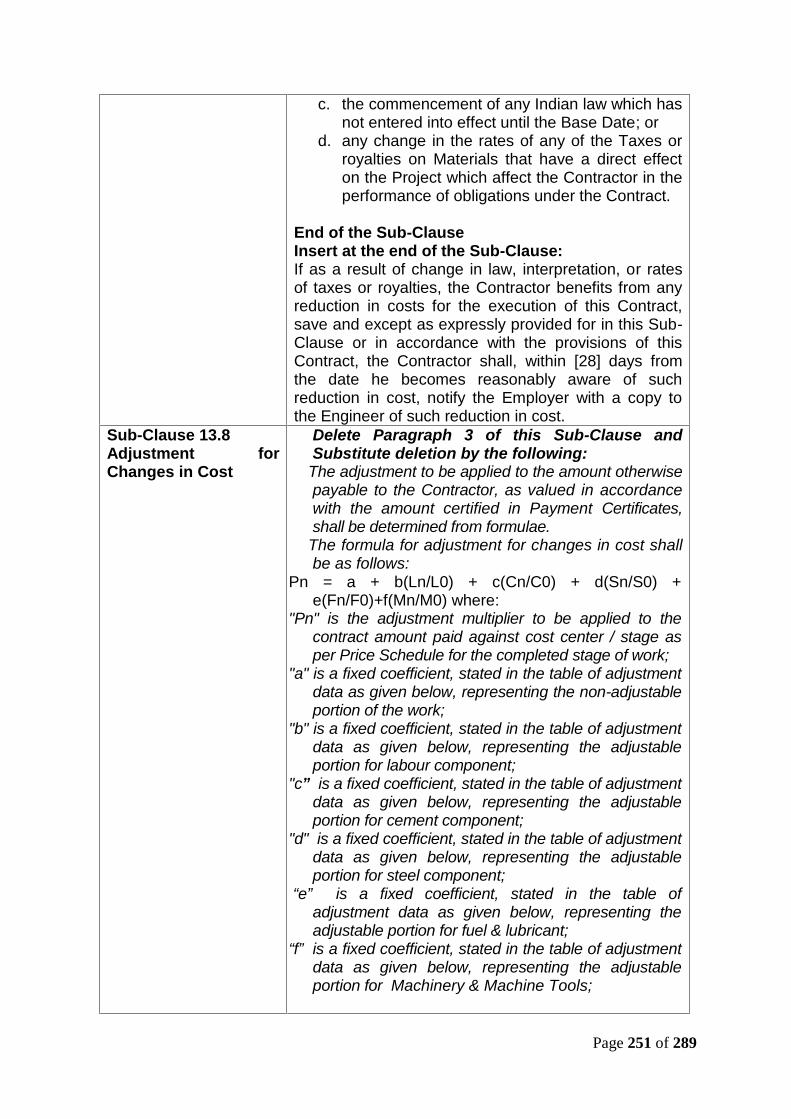
Page 251 of 289
c. the commencement of any Indian law which hasnot entered into effect until the Base Date; or
d. any change in the rates of any of the Taxes orroyalties on Materials that have a direct effecton the Project which affect the Contractor in theperformance of obligations under the Contract.
End of the Sub-ClauseInsert at the end of the Sub-Clause:If as a result of change in law, interpretation, or ratesof taxes or royalties, the Contractor benefits from anyreduction in costs for the execution of this Contract,save and except as expressly provided for in this Sub-Clause or in accordance with the provisions of thisContract, the Contractor shall, within [28] days fromthe date he becomes reasonably aware of suchreduction in cost, notify the Employer with a copy tothe Engineer of such reduction in cost.
Sub-Clause 13.8Adjustment forChanges in Cost
Delete Paragraph 3 of this Sub-Clause andSubstitute deletion by the following:
The adjustment to be applied to the amount otherwisepayable to the Contractor, as valued in accordancewith the amount certified in Payment Certificates,shall be determined from formulae.
The formula for adjustment for changes in cost shallbe as follows:
Pn = a + b(Ln/L0) + c(Cn/C0) + d(Sn/S0) +e(Fn/F0)+f(Mn/M0) where:
"Pn" is the adjustment multiplier to be applied to thecontract amount paid against cost center / stage asper Price Schedule for the completed stage of work;
"a" is a fixed coefficient, stated in the table of adjustmentdata as given below, representing the non-adjustableportion of the work;
"b" is a fixed coefficient, stated in the table of adjustmentdata as given below, representing the adjustableportion for labour component;
"c” is a fixed coefficient, stated in the table of adjustmentdata as given below, representing the adjustableportion for cement component;
"d" is a fixed coefficient, stated in the table of adjustmentdata as given below, representing the adjustableportion for steel component;
“e” is a fixed coefficient, stated in the table ofadjustment data as given below, representing theadjustable portion for fuel & lubricant;
“f” is a fixed coefficient, stated in the table of adjustmentdata as given below, representing the adjustableportion for Machinery & Machine Tools;
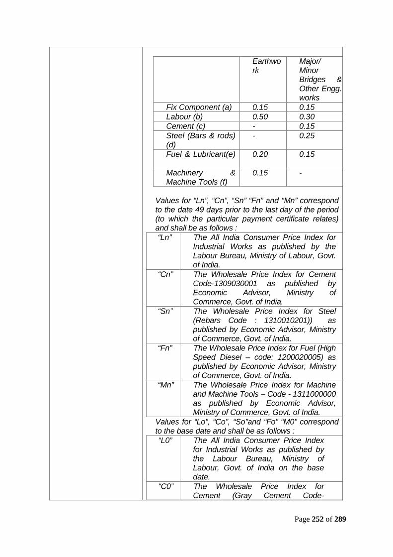
Page 252 of 289
Earthwork
Major/MinorBridges &Other Engg.works
Fix Component (a) 0.15 0.15Labour (b) 0.50 0.30Cement (c) - 0.15Steel (Bars & rods)(d)
- 0.25
Fuel & Lubricant(e) 0.20 0.15
Machinery &Machine Tools (f)
0.15 -
Values for “Ln”, “Cn”, “Sn” “Fn” and “Mn” correspondto the date 49 days prior to the last day of the period(to which the particular payment certificate relates)and shall be as follows :“Ln” The All India Consumer Price Index for
Industrial Works as published by theLabour Bureau, Ministry of Labour, Govt.of India.
“Cn” The Wholesale Price Index for CementCode-1309030001 as published byEconomic Advisor, Ministry ofCommerce, Govt. of India.
“Sn” The Wholesale Price Index for Steel(Rebars Code : 1310010201)) aspublished by Economic Advisor, Ministryof Commerce, Govt. of India.
“Fn” The Wholesale Price Index for Fuel (HighSpeed Diesel – code: 1200020005) aspublished by Economic Advisor, Ministryof Commerce, Govt. of India.
“Mn” The Wholesale Price Index for Machineand Machine Tools – Code - 1311000000as published by Economic Advisor,Ministry of Commerce, Govt. of India.
Values for “Lo”, “Co”, “So”and “Fo” “M0” correspondto the base date and shall be as follows :“L0” The All India Consumer Price Index
for Industrial Works as published bythe Labour Bureau, Ministry ofLabour, Govt. of India on the basedate.
“C0” The Wholesale Price Index forCement (Gray Cement Code-

Page 253 of 289
1309030001) as published byEconomic Advisor, Ministry ofCommerce, Govt. of India on the basedate.
“S0” The Wholesale Price Index for Steel(Rebars Code: 1310010201) aspublished by Economic Advisor,Ministry of Commerce, Govt. of Indiaon the base date.
“F0” The Wholesale Price Index for Fuel(High Speed Diesel – code:1200020005) as published byEconomic Advisor, Ministry ofCommerce, Govt. of India on the basedate.
“M0” The Wholesale Price Index numberfor Machinery and Machine toolsCode - 1311000000 as published byEconomic Advisor, Ministry ofCommerce, Govt. of India on the basedate.
Sub-Clause 14.1Contract Price
Add the following after the last paragraph –The Contract Price includes all duties, taxes, royalties,premiums for various insurances, licenses and feesthat may be levied in accordance with the laws andregulations in force as on the Base Date on theContractor's Equipment, Plant, Materials and suppliesacquired for the purpose of the Contract and on theservices performed under the Contract.Nothing in the Contract shall relieve the Contractorfrom its responsibility to pay any tax including any taxthat may be levied in India on profits made by it inrespect of the Contract.
Sub-Clause 14.2Advance Payment
Delete Paragraph 1 and substitute by thefollowing :The Employer shall make an advance payment, as aninterest bearing loan for mobilisation and design,when the contractor submits a guarantee inaccordance with this Sub-clause. The total advancepayment, the number and timing of instalments (ifmore than one), the rate of interest, and the applicablecurrencies and proportions shall be as stated in theAppendix to Tender.
Sub-Clause 14.3Application for InterimPayment Certificates
Delete first paragraph of this Sub-Clause andsubstitute by the following:The Contractor shall prepare his monthly bill, in theformat agreed with the Engineer, in six copies (hard)and a soft copy. This shall be accompanied bysupplementary details in two hard copies and a softcopy. All hard copies shall bear the original signatures
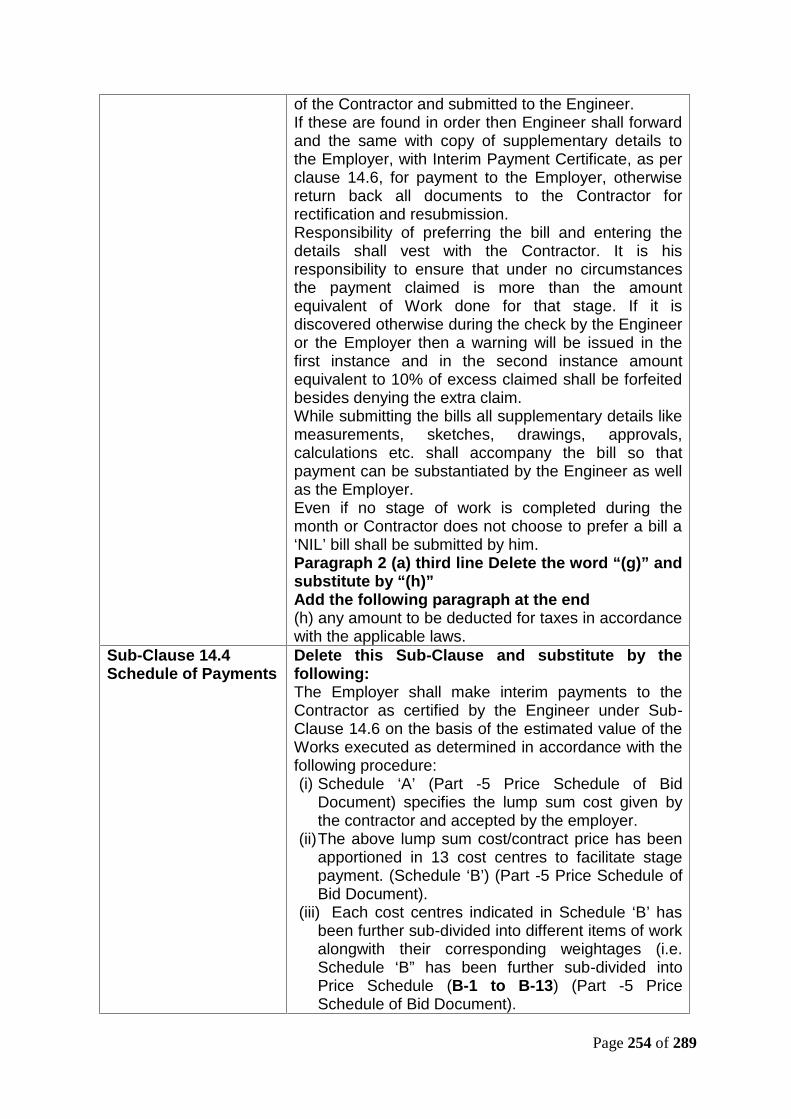
Page 254 of 289
of the Contractor and submitted to the Engineer.If these are found in order then Engineer shall forwardand the same with copy of supplementary details tothe Employer, with Interim Payment Certificate, as perclause 14.6, for payment to the Employer, otherwisereturn back all documents to the Contractor forrectification and resubmission.Responsibility of preferring the bill and entering thedetails shall vest with the Contractor. It is hisresponsibility to ensure that under no circumstancesthe payment claimed is more than the amountequivalent of Work done for that stage. If it isdiscovered otherwise during the check by the Engineeror the Employer then a warning will be issued in thefirst instance and in the second instance amountequivalent to 10% of excess claimed shall be forfeitedbesides denying the extra claim.While submitting the bills all supplementary details likemeasurements, sketches, drawings, approvals,calculations etc. shall accompany the bill so thatpayment can be substantiated by the Engineer as wellas the Employer.Even if no stage of work is completed during themonth or Contractor does not choose to prefer a bill a‘NIL’ bill shall be submitted by him.Paragraph 2 (a) third line Delete the word “(g)” andsubstitute by “(h)”Add the following paragraph at the end(h) any amount to be deducted for taxes in accordancewith the applicable laws.
Sub-Clause 14.4Schedule of Payments
Delete this Sub-Clause and substitute by thefollowing:The Employer shall make interim payments to theContractor as certified by the Engineer under Sub-Clause 14.6 on the basis of the estimated value of theWorks executed as determined in accordance with thefollowing procedure:(i) Schedule ‘A’ (Part -5 Price Schedule of Bid
Document) specifies the lump sum cost given bythe contractor and accepted by the employer.
(ii)The above lump sum cost/contract price has beenapportioned in 13 cost centres to facilitate stagepayment. (Schedule ‘B’) (Part -5 Price Schedule ofBid Document).
(iii) Each cost centres indicated in Schedule ‘B’ hasbeen further sub-divided into different items of workalongwith their corresponding weightages (i.e.Schedule ‘B” has been further sub-divided intoPrice Schedule (B-1 to B-13) (Part -5 PriceSchedule of Bid Document).

Page 255 of 289
(iv) The payment procedure has also been indicatedin each Price Schedule (B-1 to B-13) and paymentwill be done accordingly.
(v)The description of items of work in the Schedulesdoes not limit in any way the Contractor'sobligations under the Contract to provide all theWorks described in the Employer’s Requirements.
(vi) The Bidder shall compute, and supply to theEngineer, the total quantities (in units as describedin the Price Schedule) of various items of worksand components on the basis of detailed designreviewed/approved by the Engineer.
(vii) The Contractor shall base its claim for interimpayment for each stage for various items of thework on completion till the end of the month forwhich the payment is claimed, supported withdocuments and an up-dated programme inaccordance with the Employer’s Requirements.
(viii) The weightage/percentage assigned to costcentre will apply only to the Contract Price stated inthe Contract Agreement. It shall not apply to anyadditions or subtractions to the Contract Pricearising from the issue of any Variation Orders.Each Variation Order shall specify the manner ofinterim payments and completion of stages for it.
Sub Clause 14.6Issue of InterimPayment Certificates
In the 1st Paragraph, 2nd line, ‘28’ is replaced with ‘15’.
Sub Clause 14.7Payment
In the Sub Clause 14.7(b), 1st line, ‘56’ is replaced with’30’.
Sub Clause 14.9Paytment of RetentionMoney
Delete the contents of first paragraph of thisclause and replace with the following:
A Retention amounting to 10 (ten) per cent of thevalue of the work done shall be deducted by theEngineer in the first and following Interim PaymentCertificates, until the amount so retained includingRs. 1 Cr. of Bid Security retained and adjusted asRetention Money reaches a limit of Retention Moneyof 5 (five) percent of the Contract Price. When theRetention Money with the Employer has reached 60% ofthe limit of the Retention Money, the Contractor may, at hisoption, replace 50% of limit of Retention Money with anunconditional bank guarantee from the Bank, and valid forthe period up to the end of the Defect Notification Period.After the issue of taking over certificate for the completeworks, the balance amount of Retention Money can also bereplaced with an unconditional Bank Guarantee from theBank and valid for the period up to the end of DefectNotification Period.
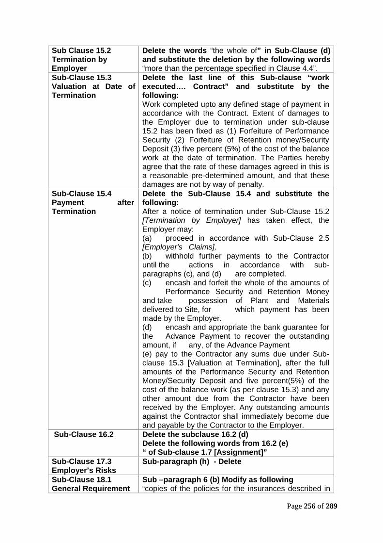
Page 256 of 289
Sub Clause 15.2Termination byEmployer
Delete the words “the whole of” in Sub-Clause (d)and substitute the deletion by the following words“more than the percentage specified in Clause 4.4”.
Sub-Clause 15.3Valuation at Date ofTermination
Delete the last line of this Sub-clause “workexecuted…. Contract” and substitute by thefollowing:Work completed upto any defined stage of payment inaccordance with the Contract. Extent of damages tothe Employer due to termination under sub-clause15.2 has been fixed as (1) Forfeiture of PerformanceSecurity (2) Forfeiture of Retention money/SecurityDeposit (3) five percent (5%) of the cost of the balancework at the date of termination. The Parties herebyagree that the rate of these damages agreed in this isa reasonable pre-determined amount, and that thesedamages are not by way of penalty.
Sub-Clause 15.4Payment afterTermination
Delete the Sub-Clause 15.4 and substitute thefollowing:After a notice of termination under Sub-Clause 15.2[Termination by Employer] has taken effect, theEmployer may:(a) proceed in accordance with Sub-Clause 2.5[Employer's Claims],(b) withhold further payments to the Contractoruntil the actions in accordance with sub-paragraphs (c), and (d) are completed.(c) encash and forfeit the whole of the amounts of
Performance Security and Retention Moneyand take possession of Plant and Materialsdelivered to Site, for which payment has beenmade by the Employer.(d) encash and appropriate the bank guarantee forthe Advance Payment to recover the outstandingamount, if any, of the Advance Payment(e) pay to the Contractor any sums due under Sub-clause 15.3 [Valuation at Termination], after the fullamounts of the Performance Security and RetentionMoney/Security Deposit and five percent(5%) of thecost of the balance work (as per clause 15.3) and anyother amount due from the Contractor have beenreceived by the Employer. Any outstanding amountsagainst the Contractor shall immediately become dueand payable by the Contractor to the Employer.
Sub-Clause 16.2 Delete the subclause 16.2 (d)Delete the following words from 16.2 (e)“ of Sub-clause 1.7 [Assignment]”
Sub-Clause 17.3Employer’s Risks
Sub-paragraph (h) - Delete
Sub-Clause 18.1General Requirement
Sub –paragraph 6 (b) Modify as following“copies of the policies for the insurances described in
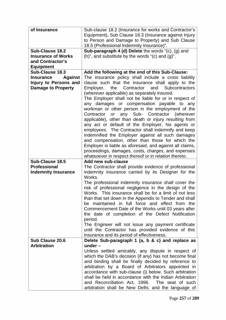
Page 257 of 289
of Insurance Sub-clause 18.2 (Insurance for works and Contractor’sEquipment), Sub Clause 18.3 (Insurance against Injuryto Person and Damage to Property) and Sub Clause18.5 (Professional Indemnity Insurance)”.
Sub-Clause 18.2Insurance of Worksand Contractor’sEquipment
Sub-paragraph 4 (d) Delete the words “(c), (g) and(h)”, and substitute by the words “(c) and (g)".
Sub-Clause 18.3Insurance AgainstInjury to Persons andDamage to Property
Add the following at the end of this Sub-Clause:The insurance policy shall include a cross liabilityclause such that the insurance shall apply to theEmployer, the Contractor and Subcontractors(wherever applicable) as separately insured.The Employer shall not be liable for or in respect ofany damages or compensation payable to anyworkman or other person in the employment of theContractor or any Sub- Contractor (whereverapplicable), other than death or injury resulting fromany act or default of the Employer, his agents oremployees. The Contractor shall indemnify and keepindemnified the Employer against all such damagesand compensation, other than those for which theEmployer is liable as aforesaid, and against all claims,proceedings, damages, costs, charges, and expenseswhatsoever in respect thereof or in relation thereto.
Sub-Clause 18.5ProfessionalIndemnity Insurance
Add new sub-clauseThe Contractor shall provide evidence of professionalindemnity insurance carried by its Designer for theWorks.The professional indemnity insurance shall cover therisk of professional negligence in the design of theWorks. This insurance shall be for a limit of not lessthan that set down in the Appendix to Tender and shallbe maintained in full force and effect from theCommencement Date of the Works until 03 years afterthe date of completion of the Defect Notificationperiod.The Engineer will not issue any payment certificateuntil the Contractor has provided evidence of thisinsurance and its period of effectiveness.
Sub Clause 20.6Arbitration
Delete Sub-paragraph 1 (a, b & c) and replace asunder –Unless settled amicably, any dispute in respect ofwhich the DAB’s decision (if any) has not become finaland binding shall be finally decided by reference toarbitration by a Board of Arbitrators appointed inaccordance with sub-clause (i) below. Such arbitrationshall be held in accordance with the Indian Arbitrationand Reconciliation Act, 1996. The seat of sucharbitration shall be New Delhi, and the language of
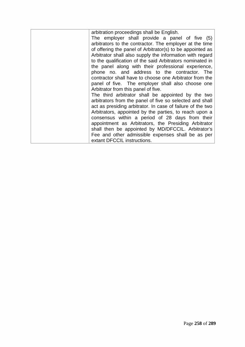
Page 258 of 289
arbitration proceedings shall be English.The employer shall provide a panel of five (5)arbitrators to the contractor. The employer at the timeof offering the panel of Arbitrator(s) to be appointed asArbitrator shall also supply the information with regardto the qualification of the said Arbitrators nominated inthe panel along with their professional experience,phone no. and address to the contractor. Thecontractor shall have to choose one Arbitrator from thepanel of five. The employer shall also choose oneArbitrator from this panel of five.The third arbitrator shall be appointed by the twoarbitrators from the panel of five so selected and shallact as presiding arbitrator. In case of failure of the twoArbitrators, appointed by the parties, to reach upon aconsensus within a period of 28 days from theirappointment as Arbitrators, the Presiding Arbitratorshall then be appointed by MD/DFCCIL. Arbitrator’sFee and other admissible expenses shall be as perextant DFCCIL instructions.

Page 259 of 289
APPENDIX TO TENDERItem GC Sub-
ClauseData
Employer 1.1.2.2,1.3
Dedicated Freight Corridor Corporation of India Limited,5th Floor Pragati Maidan, Metro Station Building ComplexNew Delhi, India – 110001
Contractor 1.1.2.3 &1.3
To be filled in
Engineer 1.1.2.4,1.3 & 3.1
to be filled in
Time for Completion 1.1.3.3 As per Sub-clause 8.2 of GCDefects NotificationPeriod
1.1.3.7 Defect Notification Period for the Works shall be twoyears from the date of Taking Over of the Works (Sub-clause 10.1) and issue of Taking-Over Certificate by theEngineer.
Communications 1.3 By fax and e-mails but confirmed in hard paper copywithin 48 hours.
Law and Language 1.4 Indian Laws & English LanguageRight of Access to theSite
2.1 The Employer shall give Right to Access to site to theContractor as per the following schedule subject to theContractor providing Performance Security in terms ofSub-Clause 4.2 of General Conditions of Contract.SN Period
afterCommencementDate indays
Site to be handed over for work withrespect to total length
1 28 (i) Site for construction of quarters,(ii) Site for viaduct, RFO & its
approach span near RFOapprox. 1 Km stretch,
(iii) Site for construction of watertank at DOS.
2 91 (i) Site for Major Bridges,(ii) Site for 25% of Minor Bridges
and RUBs,(iii) Ch. 225.975 to Ch. 580 of
Viaduct.3 180 (i) Site from Sone Bridge up to
existing ROB at east end of DOSYard,
4 240 (i) Balance site of Viaduct from Ch.580 to Ch. 1700 including UP &DN lines to/from CPBH subjectto construction of approx.162units of staff quarters, tank,tubewell etc. in all respect within180 days of handover of site,
(ii) Site for UP & DN lines to / fromCPBH/SEB.
5 365 (i) Site for SEB – NSEB formationfrom Ch. 2600 to 8460 (near
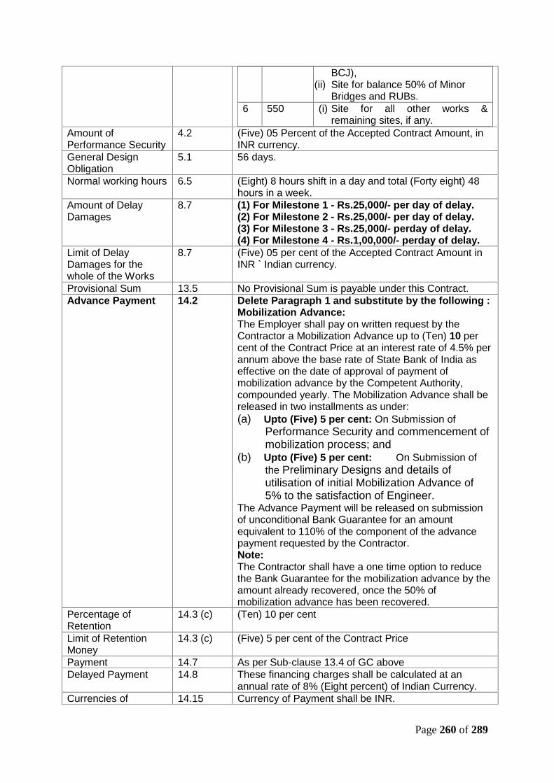
Page 260 of 289
BCJ),(ii) Site for balance 50% of Minor
Bridges and RUBs.6 550 (i) Site for all other works &
remaining sites, if any.Amount ofPerformance Security
4.2 (Five) 05 Percent of the Accepted Contract Amount, inINR currency.
General DesignObligation
5.1 56 days.
Normal working hours 6.5 (Eight) 8 hours shift in a day and total (Forty eight) 48hours in a week.
Amount of DelayDamages
8.7 (1) For Milestone 1 - Rs.25,000/- per day of delay.(2) For Milestone 2 - Rs.25,000/- per day of delay.(3) For Milestone 3 - Rs.25,000/- perday of delay.(4) For Milestone 4 - Rs.1,00,000/- perday of delay.
Limit of DelayDamages for thewhole of the Works
8.7 (Five) 05 per cent of the Accepted Contract Amount inINR ` Indian currency.
Provisional Sum 13.5 No Provisional Sum is payable under this Contract.Advance Payment 14.2 Delete Paragraph 1 and substitute by the following :
Mobilization Advance:The Employer shall pay on written request by theContractor a Mobilization Advance up to (Ten) 10 percent of the Contract Price at an interest rate of 4.5% perannum above the base rate of State Bank of India aseffective on the date of approval of payment ofmobilization advance by the Competent Authority,compounded yearly. The Mobilization Advance shall bereleased in two installments as under:(a) Upto (Five) 5 per cent: On Submission of
Performance Security and commencement ofmobilization process; and
(b) Upto (Five) 5 per cent: On Submission ofthe Preliminary Designs and details ofutilisation of initial Mobilization Advance of5% to the satisfaction of Engineer.
The Advance Payment will be released on submissionof unconditional Bank Guarantee for an amountequivalent to 110% of the component of the advancepayment requested by the Contractor.Note:The Contractor shall have a one time option to reducethe Bank Guarantee for the mobilization advance by theamount already recovered, once the 50% ofmobilization advance has been recovered.
Percentage ofRetention
14.3 (c) (Ten) 10 per cent
Limit of RetentionMoney
14.3 (c) (Five) 5 per cent of the Contract Price
Payment 14.7 As per Sub-clause 13.4 of GC aboveDelayed Payment 14.8 These financing charges shall be calculated at an
annual rate of 8% (Eight percent) of Indian Currency.Currencies of 14.15 Currency of Payment shall be INR.

Page 261 of 289
PaymentEvidence ofInsurance
18.1 (a),18.5
Before Commencement Date of Works
Relevant Policies 18.1(b) Within 84 days of Commencement Date of WorksInsurance of Worksand ContractorsEquipment
18.2 Full Replacement Cost+15%; The Insurance Policy tocover the Employer’s Risk as per Sub-Clause 17.3 ofGC shall be taken by the Employer.
Minimum amount ofthird party Insurance
18.3 Rs. 50 lakh for any one occurrence.
ProfessionalIndemnity Insurance
18.5 Rs. Two Crores
Appointment ofDispute AdjudicationBoard
20.2 The DAB shall comprise of one Sole member and solemember shall be appointed by ManagingDirector/DFCCIL. List of DAB members will be providedto the contractor by the Employer within three months ofcommencement date.
Failure to AgreeDispute AdjudicationBoard
20.3 (d) Managing Director/DFCCIL

Page 262 of 289
CONTRACT FORMS
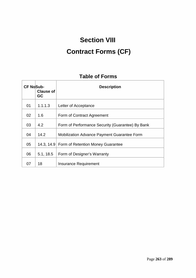
Page 263 of 289
Section VIIIContract Forms (CF)
Table of Forms
CF NoSub-Clause ofGC
Description
01 1.1.1.3 Letter of Acceptance
02 1.6 Form of Contract Agreement
03 4.2 Form of Performance Security (Guarantee) By Bank
04 14.2 Mobilization Advance Payment Guarantee Form
05 14.3, 14.9 Form of Retention Money Guarantee
06 5.1, 18.5 Form of Designer’s Warranty
07 18 Insurance Requirement

Page 264 of 289
CF-1
LETTER OF ACCEPTANCE(Sub-Clause 1.1.1.3)
To
Date:…………………….
Dear Sir
Project: Design and Construction of Formation in Embankments/Cuttingsincluding blanketing, Viaducts, Rail Flyover, Bridges (Major, Minor &RUBs), Supply and Spreading of Ballast and other related infrastructuralworks for double track electrified railway line on Design Build LumpSum Basis from Howrah end approach of DFC Sone bridge toChirailapathu station of IR towards Howrah & to New Sonnagar stationtowards Garhwa and at Dehri-on-Sone yard from Km. 3.16 to Km. 5.38 inconnection with Eastern Dedicated Freight Corridor in the state of Biharin India.
To,
This is to notify you that your bid proposal dated…………..for execution of the aboveProject for the firm Contract Price of …………………….………………… (INR) and ascorrected and modified in accordance with the bidding documents, is herebyaccepted by DFCC.
You are requested to furnish the performance security as required by the contractand bidding document.
You are hereby instructed to proceed and prepare your mobilization for the executionof the said Contract works. Contract Agreement documents will be prepared andforwarded to you for signature.
Yours truly,
For – Dedicated Freight Corridor Corporation of India Limited
(___________________)
Name:……………………….
Signature
Stamp
Page 265 of 289
CF-2 CF-2
CONTRACT AGREEMENT(Sub-Clause 1.6 of General Conditions of Contract)
THIS AGREEMENT (“Agreement”) is made at New Delhi on the ________ day of________________________, _____,
BETWEEN
(1) Dedicated Freight Corridor Corporation of India Limited, incorporated under thelaws of India and having its principal place of business at 5th Floor, Pragati MaidanMetro Station Building Complex, New Delhi, India – 110001 (hereinafter called ‘theEmployer’), and ------------------------------------------, a company/corporation/JVincorporated under the laws of ------------having its principal place of business at ----------------------------------- (hereinafter called “the Contractor”).
WHEREAS the Employer desires to engage the Contractor to
Design and Construction of Formation in Embankments/Cuttings includingblanketing, Viaducts, Rail Flyover, Bridges (Major, Minor & RUBs), Supply andSpreading of Ballast and other related infrastructural works for double trackelectrified railway line on Design Build Lump Sum Basis from Howrah end approachof DFC Sone bridge to Chirailapathu station of IR towards Howrah & to New Sonnagarstation towards Garhwa and at Dehri-on-Sone yard from Km. 3.16 to Km. 5.38 inconnection with Eastern Dedicated Freight Corridor in the state of Bihar in Indiacontract package (“the Works”), and the Contractor has agreed to suchengagement upon and subject to the terms and conditions hereinafter appearing.
NOW IT IS HEREBY AGREED as follows:
Article 1.
ContractDocuments
1.1Contract Documents (Reference GC Clause 1.5)
The following documents shall constitute the Contractbetween the Employer and the Contractor, and eachshall be read and construed as an integral part of theContract:
(a)This Contract Agreement and the Appendices hereto
(b)Letter of Acceptance
Page 266 of 289
(c) Letter of Bid and Price Schedules submitted by theContractor
(d)Particular Conditions & Appendix to Tender
(e)General Conditions
(f) Employer’s Requirements
(g)Contractors Technical & Financial Proposal;
(h)Information furnished in Part 4 of Bidding document
(i) Other completed bidding forms submitted with the Bid;and
(j) Any other documents forming part of the Employer’srequirements and Bidding documents.
1.2 Definitions (Reference GC clause 1 and Employer’sRequirement).
Capitalised words and phrases used herein shall have thesame meanings as are ascribed to them in the GeneralConditions and Employer’s Requirement.
Article 2.
Contract Price andTerms of Payment
2.1 Contract Price (Reference GC Clause 14.1)
The Employer hereby agrees to pay to the Contractorthe Contract Price in consideration of the performanceby the Contractor of its obligations pursuant to theContract. The Contract Price shall be as specified inSchedule A Price Schedule, or such other sums as maybe determined in accordance with the terms andconditions of the Contract.
2.2 Terms of Payment (Reference GC Clause 14.4)
The terms and procedures of payment according towhich the Employer will reimburse the Contractor aregiven in Terms and Procedures of Payment subject tosuch additions thereto or deductions there from as maybe made under the provisions of the contract at thetimes and in the manner prescribed by the Contract.
The amount payable under Schedule – B (B-1 to B-13) isadjusted in accordance with GC 13.8 or with any of theother terms of the Contract.
Article 3. 3.1 Commencement Date (Reference GC Clause 1.1.3.2)
Page 267 of 289
CommencementDate
42days from the date of receipt of letter of acceptance oras indicated in the Letter of Acceptance.
Article 4.
Time forCompletion
4.1 Completion (Reference Clause 1.1.3 GC & ----Employer’s Requirements)
In consideration of the payments to be made by theEmployer to the Contractor as hereinafter mentioned,the contractor hereby covenants with the Employer toexecute and complete the Works by 900 days andremedy any defects therein in conformity in allrespects with the provisions of the Contract.
Article 5.Communications
5.1 The address of the Employer for notice purposes,pursuant to GC 1.3 is:
The Director Project & Planning,
Dedicated Freight Corridor Corporation,
5th Floor Pragati Maidan, Metro Station Building Complex
New Delhi, India – 110001
5.2 The address of the Contractor for notice purposes,pursuant to GC 1.3 is: ___________________.
Article 6.
Obligations of theContractor
6.1 Contractor’s General Obligation GC 4.1
The Contractor shall ensure full compliance with the lawsof India including taxation and other fiscal laws, withregard to the Contract and the Works shall be solelyresponsible for the same. The Contractor shall submitcopies of acknowledgements evidencing filing of returnsevery year and shall keep the Employer fully indemnifiedagainst liability of levies, custom duties, tax, interest,penalty etc. of the Contractor in respect thereof, whichmay arise.
IN WITNESS WHEREOF the parties hereto have caused their respective CommonSeals to be hereunto affixed/ (or have hereunto set their respective hands and seals)the day and year first above written.
For and on behalf of the Contractor For and on behalf of the Employer

Page 268 of 289
Signature of the authorized official Signature of the authorized official
Name of the official Name of the official
Stamp/seal of the Contractor Stamp/Seal of the Employer
SIGNED, SEALED AND DELIVERED
By the said By the said
__________________________Name _______________________Name
__________________________ _________________________
on behalf of the Contractor in the on behalf of the Employer in the
presence of: presence of:
Witness _____________________ Witness __________________
Name _______________________ Name ____________________
Address _____________________ Address __________________
****

Page 269 of 289
CF-3
SAMPLE FORM OF PERFORMANCE SECURITY(GURANTEE) BY BANK
(Sub-Clause 4.2)
This deed of guarantee made this day of ……………. Between Bank of (hereinaftercalled the “Bank”) of the one part, and Dedicated Freight Corridor Corporation ofIndia Limited called the “Employer” of the other part.
Whereas Dedicated Freight Corridor Corporation of India Limited has awarded thecontract for …………………………………… (Hereinafter called the Contract) to…………………. (Hereinafter called the Contractor). (Name of the Contractor)
AND WHEREAS the Contractor is bound by the said Contract to submit to theEmployer a Performance Security for a total amount of Rs……… (Amount in figuresand words). Now we the undersigned ………………………………………..(Name ofthe Bank) being fully authorized to sign and to incur obligations for and on behalf ofand in the name of ………………………..(full name of the Bank), hereby declare thatthe said bank will guarantee the Employer the full amount of Rs. ……………………(Amount in figures and words).
After the Contractor has signed the aforementioned Contract with the Employer, theBank is engaged to pay the Employer, any amount up to and inclusive of theaforementioned full amount of the Performance Security upon written order from theEmployer to indemnify the Employer for any liability of damage resulting from anydefects or shortcomings of the Contractor or the debts he may have incurred to anyparties involved in the Works under the Contract mentioned above, whether thesedefects or shortcomings or debts are actual or estimated or expected. The Bank willdeliver the money required by the Employer immediately on demand without delayand demur and without reference to the Contractor and without the necessity of aprevious notice or of judicial; or administrative procedures and without it beingnecessary to prove to the Bank the liability or damages resulting from any defects orshortcomings or debts of the Contractor. The Bank shall pay to the Employer anymoney so demanded notwithstanding any dispute/disputes raised by the contractorin any suit or proceedings pending before any court, Tribunal or Arbitrator/s relatingthereto and the liability under this guarantee shall be absolute and unequivocal.
This guarantee is valid till ……………..(the initial period for which this Guarantee willbe valid must be for at least 6 months (six months) longer than the anticipatedexpiry date of Defects Notification Period as stated in Clause 1.1.3.7 of theAppendix to Tender.
At any time during the period in which this guarantee is still valid, if the Employeragrees to grant a time extension to the Contractor or if the Contractor fails tocomplete the Works within the time of completion as stated in the Contract, or fails todischarge himself of the liability or damages or debts as stated in the Contract, or
Page 270 of 289
fails to discharge himself of the liability or damages or debts as stated in theContract, it is understood that the Bank will extend this guarantee under the sameconditions for the required time on demand by the Employer and at the cost of theContractor.
The Guarantee hereinbefore contained shall not be affected by any change in theConstitution of the Bank or of the Contractor.
The neglect or forbearance of the Employer in enforcement of payment of anymoneys, the payment whereof is intended to be hereby secured or the giving of timeby the Employer for the payment hereof shall in no way relieve the Bank of theirliability under this deed.
The expressions “the Employer”, “the Bank” and “the Contractor” hereinbeforeused shall include their respective successors and assigns.
Notwithstanding anything contained herein:
Our liability under this bank Guarantee shall not exceed Rs…….(Rupees…………………………).
This bank guarantee shall be valid up to ………………….
We are liable to pay the guarantee amount or part thereof under this bank Guaranteeonly and only if you serve upon us a written claim or demand on or before……………
In witness whereof I/We of the Bank have signed and sealed this guarantee on the………… day of ………….. (Month) being herewith duly authorized.
For and on behalf of
The ………………….bank
Signature of Authorized bank Official
Name ……………………..
Designation ……………………..
Stamp/seal of the Bank:……………..
Signed, sealed and delivered

Page 271 of 289
For and on behalf of the
Bank of the above
Name____________
In The presence of :
Witness 1. Witness 2.
Signature …………………… Signature …………………..
Name ………………………… Name ………………………
Address ……………………… Address …………………….
***

Page 272 of 289
CF-4
SAMPLE FORM FOR MOBILISATION ADVANCE PAYMENTGUARANTEE
(Sub-Clause 14.2)
Bank guarantee made on this …………………………………. Between……………………… (hereinafter called “the Bank”) of the One Part and DedicatedFreight Corridor Corporation of India Limited. (hereinafter called “the Employer”) ofthe other Part.
WHEREAS Dedicated Freight Corridor Corporation of India Limited has awarded theContract no…………. for “………………………………….” (hereinafter called “theContract”) to ………………. Having its registered office at………………………………. (hereinafter called “the Contractor”).
AND WHEREAS vide Clause 14.2 of the General Conditions of Contract,Mobilization Advance up to ---% (--- percent) of the original contract value ofRs………………….. is payable to the contractor against Bank Guarantees, theContractor hereby applies for Mobilization Advance of --% (--- percent) amounting toRs……………………../- (Rupees…………………………………..) of the ContractPrice, as per Appendix to Tender
AND WHEREAS this Bank Guarantee is for Rs…………………./-(Rupees…………………..) being the 1st one of the two Bank Guarantees,
totalling to the above Mobilization Advance amount of Rs……………………/-.
Now, we the undersigned, Bank of …………., being fully authorized to sign and toincur obligations for and on behalf of and in the name of Bank of ……………..herebydeclare that the said Bank will guarantee the Employer the full amount of Rs.…………………../- (Rupees……………………………………..) as stated above.
We, Bank of ………………., do hereby unconditionally, irrevocably and withoutdemur guarantee and undertake to pay the Employer immediately on demand any orall money payable by the Contractor to the extent of Rs. ………………./-(Rupees………………………..) without any demur, reservation, context, recourse orprotest and/or without any reference to the Contractor. Any such demand made bythe Employer on the Bank shall be conclusive and binding notwithstanding anydifference between the Employer and the Contractor on any dispute pending beforeany court, Tribunal, Arbitrator or any other authority. We agree that the guaranteeherein contained shall be irrevocable and shall continue to be enforceable till theEmployer discharges this guarantee.
This guarantee is valid till ……………………………..
At any time during the period in which this guarantee still valid of the Contractor failsto fulfill its obligation under the Contract, it is understood that the Bank will extend

Page 273 of 289
this guarantee under the same condition for the required time on demand by theEmployer at the cost of the Contractor.
The Guarantee hereinbefore contained shall not be affected by any change in theconstitution of the Bank or of the Contractor.
The neglect or forbearance of the Employer in enforcement of payment of anymoney, the payment whereof is intended to be hereby secured or the giving of timeby the Employer for the payment hereof shall in no way relieve the Bank of theirliability under this Deed.
The expressions “the Employer”, “the Bank” and “the Contractor” hereinbefore usedshall include their respective successors and assigns.
Notwithstanding anything contained herein:
Our liability under this Bank Guarantee shall not exceed Rs………………./-(Rupees…………….)
this bank Guarantee shall be valid up to………………….
We are liable to pay the guaranteed amount or any part thereof under this BankGuarantee only and only if you serve upon us a written claim or demand on or before……………(date of expiry of Guarantee).
In witness whereof we of the Bank have signed and sealed this Guarantee on the…………………day of …………..being herewith duly authorized.
For and on behalf of the Bank of……….
Signature of Authorized Bank Official
Name ________________________
Designation ________________________
Stamp/Seal of the bank ________________________
Signed, sealed and delivered for and on
Behalf of the bank by the above named
………….. in the presence of
Witness 1
Signature ___________________
Name ___________________
Address ___________________
Witness 2

Page 274 of 289
Signature ___________________
Name ___________________
Address ___________________
****
Page 275 of 289
CF-5
SAMPLE FORM OF RETENTION MONEY GUARANTEE(Sub-Clause 14.3 c, 14.9)
Brief description of Contract
Name and address of Beneficiary
__________________________________ (whom the Contract defines as theEmployer).
We have been informed that _________________ (hereinafter called the “Principal”)is your Contractor under such Contract and wishes to receive early payment of [partof] the retention money, for which the Contract requires him to obtain a guarantee.
At the request of the Principal, we (name of bank) ________________________hereby irrevocably undertake to pay you, the Beneficiary / Employer, any sum orsums not exceeding in total the amount of __________________ (the “GuaranteedAmount”, say: ____________) upon receipt by us of your demand in writing and yourwritten statement stating:
a) that the Principal has failed to carry out his obligation(s) to rectify certain defect(s)for which he is responsible under the Contract, and
b) the nature of such defect(s).
c) That the Principal has failed to carry out his obligation(s) for which he isresponsible under the Contract,
At any time, our liability under this guarantee shall not exceed the total amount ofretention money released to the Principal by you, as evidenced by your noticesissued under Sub-Clause 2.5 and 14.9 of the Conditions of the Contract with a copybeing passed to us.
Any demand for payment must contain your signature(s) which must beauthenticated by your Bankers. The authenticated demand and statement must bereceived by us at this office on or before (the date 56 days after the expected expiryof the Defects Notification Period for the Works) _____________ (the “ExpiryDate”), when this guarantee shall expire and shall be returned to us.
We have been informed that the Beneficiary may require the Principal to extend thisguarantee if the performance certificate under the Contract has not been issued bythe date 28 days prior to such Expiry Date. We undertake to pay you suchGuaranteed Amount upon receipt by us, within such period 28 days, of your demandin writing and your written statement that the performance certificate has not beenissued, for reasons attributable to the Principal, and that this guarantee has not beenextended.

Page 276 of 289
This guarantee shall be governed by the laws of Republic of India.
Date Signature(s)
****

Page 277 of 289
CF-6
SAMPLE FORM OF DESIGNER’S WARRANTY(Sub-Clause 5.1 and Sub-Clause 18.5)
THIS AGREEMENT is made the day of
BETWEEN:
(1) [ ] [whose registered office is at]/[of] [ ] ("theDesigner"); and
(2) The Dedicated Freight Corridor Corporation India Limited (together with itssuccessors and assigns, "the Employer") of
5th Floor, Pragti Maidain Metro Station,
New Delhi,
India 110001.
WHEREAS:
(a) By a contract --------- dated [ ] ("the Contract") made between (1)Dedicated Freight Corridor Corporation India Limited (“the Employer”) and (2)[ ] ("the Contractor"), the Contractor has agreed to design, executecomplete test and remedy any defect in the Works upon the terms andconditions contained in the Contract.
(b) The Designer has had an opportunity of reading and noting the provisions ofthe Contract (other than details of the Contractor's prices and rates).
(c) Pursuant to the Contract, the Contractor wishes to enter into an agreementwith the Designer and Designer agrees to the wishes of the Contractor (theConsultancy agreement) to carry out the Contractor's obligations under theContract in relation to the design and functions ascribed to the Designer in theContract.
(d) The Contract stipulates that the Contractor shall ensure that the Designerexecutes a warranty agreement (“Warranty”) in favour of the Employer.
NOW IT IS HEREBY AGREED as follows:

Page 278 of 289
1 In consideration of the Employer not objecting to the Contractor and theDesigner entering into the Consultancy Agreement, the Designer warrantsand undertakes to the Employer that he has exercised and will continue toexercise all the skill and care to be expected of a professionally qualified andcompetent designer experienced in work of similar nature and scope as theWorks in carrying out the design of the temporary and Permanent Works andin performing the other duties and functions ascribed to him in the Contract.
2 The Designer agrees that, in the event of the termination of the Contract bythe Employer or its appointee, the Designer will, if so required by notice inwriting given by the Employer, accept subject to Clause 4 given herein, theinstructions of the Employer or his appointee to the exclusion of theContractor in respect of the carrying out and completion of the Works uponthe terms and conditions of the Consultancy Agreement.
3 The Designer further agrees that he will not, without first giving the Employernot less than 21 days' previous notice in writing, exercise any rights it mayhave to terminate the Consultancy Agreement or to treat the same as havingbeen as repudiated by the Contractor or to discontinue the performance ofany duties to be performed by the Designer pursuant thereto. The Designer'sright to terminate the Consultancy Agreement or to treat the same as havingbeen repudiated or to discontinue the performance thereof shall cease if,within such period of notice and subject to Clause 4, the Employer shall givenotice in writing to the Designer requiring the Designer to accept theinstructions of the Employer or his appointee to the exclusion of theContractor in respect of the carrying out and completion of the Contract Worksupon the terms and conditions of the Consultancy Agreement.
4 Any notice given by the Employer under Clause 2 or 3 above shall state thatthe Employer or his appointee accepts liability for payment of the fees payableto the Designer under the Consultancy Agreement and for performance of theContractor's obligations under the Consultancy Agreement, including paymentof any fees outstanding at the date of such notice.
5 The Employer shall be entitled to assign the benefit of this Warranty at anytime without the consent of the Designer being required.
6 All documents arising out of or in connection with this Warranty shall beserved:
(1) upon the Employer at [ ] marked for the attention of [];
(2) upon the Designer at [ ].
7 The Employer and the Designer may change their respective nominatedaddresses for service of documents to another address in India but only byprior written notice to each other. All demands and notices must be in writing.
8 This Warranty shall be governed by and construed according to the laws forthe time being in force in India.

Page 279 of 289
9 (i) In the event that the Contract or the employment of the Contractorunder the Contract is terminated for any reason whatsoever and if sorequested by the Employer in writing within 21 days of suchtermination, the Designer shall carry out and complete his obligationsunder this Warranty and shall enter into a novation agreement with theEmployer and the Contractor in which the Designer will undertake interalia to perform the Design and be bound by its terms and conditions asif the Employer had originally been named as a contracting party inplace of the Contractor. The said novation agreement will be in suchform as the Employer may reasonably require.
(ii) In the event that the Employer does not require the Designer to enterinto a novation agreement as required by Sub-clause 9 (i), theDesigner shall have no claim whatsoever against the Employer for anydamage, loss or expense howsoever arising out of or in connectionwith this Warranty.
Except to the extent (if any) expressly permitted by the ConsultancyAgreement, the Designer shall not sub-contract any of the Designer'sobligations under the Consultancy Agreement without the prior written consentof the Engineer.
10 Without prejudice to its obligations under this Warranty, the Designer shallmaintain with well established underwriters of repute and on terms andconditions reasonably acceptable to the Employer, professional indemnityinsurance (as per sub-clause 18.5 of the Particular Conditions of Contract) inrespect of the Designer and its sub-consultants for Indian Rupees Two Crores(2,00,00,000 Rupees) in relation to his design of the Works for any oneoccurrence or series of occurrences arising out of any one event from the dateof notification of acceptance until 3 years after the issue of PerformanceCertificate for the whole of works. The Designer shall immediately inform theEmployer if for any reason professional indemnity insurance is not maintainedin accordance with this Warranty or becomes void or unenforceable.
11 Insofar as the patent, copyright or other intellectual property rights in anyDesign Data (as defined in the Contract), plans, calculations, drawings,documents, materials, computer software, know-how and information relatingto the Works shall be vested in the Designer, the Designer grants to theEmployer his successors and assigns a royalty-free, non-exclusive andirrevocable license (carrying the right to grant sub-licenses) to use andreproduce any of the works designs or inventions incorporated and referred toin such documents or materials and any such know-how and information forall purposes relating to the Works (including without limitation the design,construction, reconstruction, completion, reinstatement, extension, repair andoperation of the Works). To the extent beneficial ownership of any suchpatent, copyright or other intellectual property right is vested in anyone otherthan the Designer or the Contractor, the Designer shall use his bestendeavors to procure that the beneficial owner thereof shall grant a likelicense to the Employer. Any such license granted shall not be determined ifthe Designer shall for any reason cease to be employed in connection with theWorks.
Page 280 of 289
12 (i) Any dispute or difference of any kind whatsoever between theEmployer and the Designer arising under out of or in connection withthis Warranty shall be referred to arbitration in accordance with Clause20 of GC “Dispute” as defined in the Contract shall be deemed toinclude any such dispute or difference between the Employer and theDesigner.
(ii) In the event that the Employer is of the opinion that the issues in such adispute or difference will or may touch upon or concern a dispute ordifference arising under out of or in connection with the Contract ("theContract Dispute") then provided that an Arbitrator has not alreadybeen appointed, the Employer may by notice in writing to the Designerrequire and the Designer shall be deemed to have consented to thereferral of such dispute or difference to the Arbitrator to whom theContract Dispute has been or will be referred.
(iii) Save as expressly otherwise provided, the Arbitrator shall have fullpower to open up, review and revise any decision, opinion, instruction,notice, order, direction, withholding of approval or consent, statementof objection, determination, certificate, assessment or valuation by theEngineer or the Contractor, relating to the dispute or difference.
(iv) This Warranty shall be governed by and construed according to thelaws for the time being in force in India and the Designer agrees tosubmit to the jurisdiction of the courts of Delhi/New Delhi.
IN WITNESS whereof this Warranty has been executed as a deed on the date firstbefore written.
THE COMMON SEAL of
[Designer ]
was affixed hereto in
the presence of:-
*****
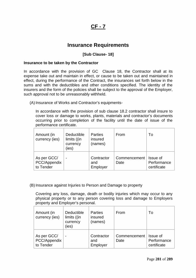
Page 281 of 289
CF - 7
Insurance Requirements[Sub Clause- 18]
Insurance to be taken by the Contractor
In accordance with the provision of GC Clause 18, the Contractor shall at itsexpense take out and maintain in effect, or cause to be taken out and maintained ineffect, during the performance of the Contract, the insurances set forth below in thesums and with the deductibles and other conditions specified. The identity of theinsurers and the form of the policies shall be subject to the approval of the Employer,such approval not to be unreasonably withheld.
(A) Insurance of Works and Contractor’s equipments-
In accordance with the provision of sub clause 18.2 contractor shall insure tocover loss or damage to works, plants, materials and contractor’s documentsoccurring prior to completion of the facility until the date of issue of theperformance certificate.
Amount (incurrency (ies)
Deductiblelimits ((incurrency(ies)
Partiesinsured(names)
From To
As per GCC/PCC/Appendixto Tender
- ContractorandEmployer
CommencementDate
Issue ofPerformancecertificate
(B) Insurance against Injuries to Person and Damage to property
Covering any loss, damage, death or bodily injuries which may occur to anyphysical property or to any person covering loss and damage to Employersproperty and Employer’s personal.
Amount (incurrency (ies)
Deductiblelimits ((incurrency(ies)
Partiesinsured(names)
From To
As per GCC/PCC/Appendixto Tender
- ContractorandEmployer
CommencementDate
Issue ofPerformancecertificate
Page 282 of 289
(C ) Automobile liability Insurance -
Covering use of all vehicles used by the contractors or its sub contractors(whether or not owned by them) in connection with the design, constructiontesting and commissioning of the facilities under the contract in accordancewith statutory requirements.
(D) Workers’ Compensation -
In accordance with the statutory requirements applicable in any countrywhere the facilities or any part thereof is executed.
(E) Professional Indemnity Insurance-
To cover professional negligence in the design of the Works.
Amount (incurrency (ies)
Deductiblelimits ((incurrency(ies)
Partiesinsured(names)
From (Place) To (Place)
As per GCC/PCC/Appendixto Tender
- ContractorandEmployer
CommencementDate
3 Yearsbeyonddefectliabilityperiod
Insurance to be taken by the Employer - Nil
****
Page 283 of 289
PART – 4
Reference Documents

Page 284 of 289
Reference DocumentsThe technical data provided by the Employer in Site Details - Part 4 of BiddingDocument like plan and profile, Chainages, GAD of bridges/viaduct, geotechnicaldetails, hydrological data, linear water way etc. for bridges are indicative. Howevernumber of bridges, level crossings, RUBs, RFOs, Buried Boxes and charteredutilities are firm and any change (in numbers) will be treated as a variation.
(1) List of various structures like viaduct, major bridges, minor bridges, railflyovers, LCs and chartered utilities are given below:
(A) Section: Ch. 225.975 (HWH end approach of Sone bridge) to approx Ch. 8460(connection at New Sonnagar near Bagaha Bishnupur towards Garhwa IR lines)double line track through viaduct on one end (MGS end of RFO), Rail Flyover andembankment towards Garhwa end :
(i) Details of Viaduct-
S.No. Bridge No. Ch. Clear Span (m)1 G1 (Viaduct) 415 - 2285 220 x 6.5m x varying
height
(ii) Details of Railway Flyover-
S.No. Bridge No. Ch. Clear Span1 G2 (RFO) 2340 1x76.2m SG + 1x45.7m
SG + 1x12.2mPSC/Composit/SteelGirder
(iii) Details of ROB-
S.No. Bridge No. Ch. Clear Span1 G10 4900 2 Nos. 1x60 m RDSO Bow
String Girder
(iv) Details of Major Bridges-
S.No. Bridge No. Ch. Clear Span1 G4 3296.39 2x30.5m PSC Girder
(v)Details of Minor Bridges-
S.No Proposed Br. No. Proposed Ch. Proposed Span
1. G2A 2570.40 1x2x2 M RCC Box
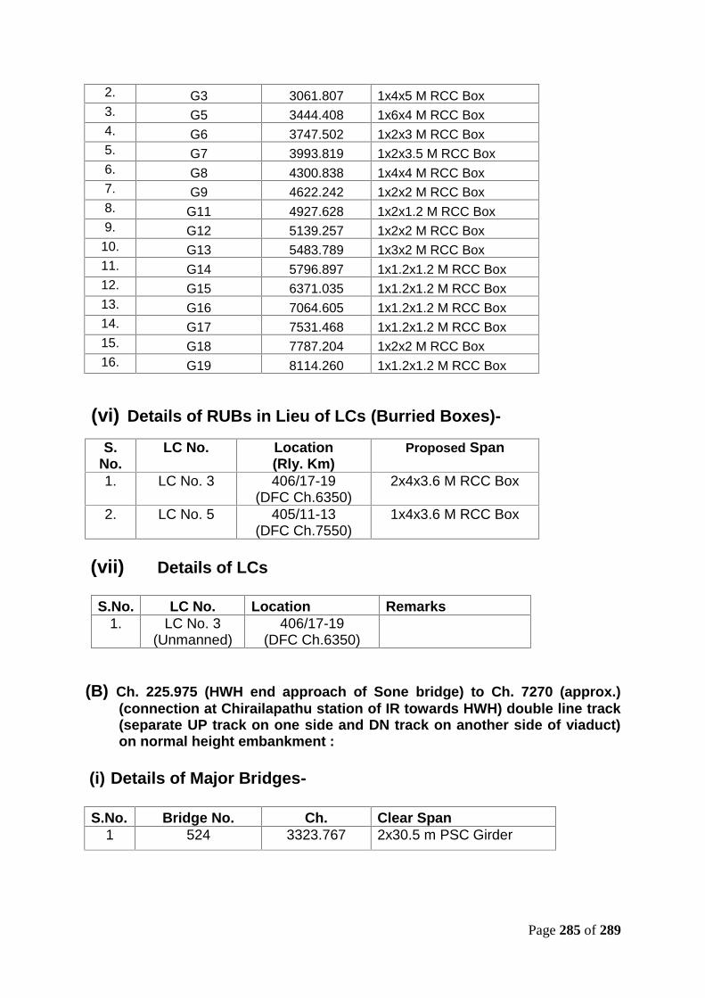
Page 285 of 289
2. G3 3061.807 1x4x5 M RCC Box3. G5 3444.408 1x6x4 M RCC Box4. G6 3747.502 1x2x3 M RCC Box5. G7 3993.819 1x2x3.5 M RCC Box6. G8 4300.838 1x4x4 M RCC Box7. G9 4622.242 1x2x2 M RCC Box8. G11 4927.628 1x2x1.2 M RCC Box9. G12 5139.257 1x2x2 M RCC Box10. G13 5483.789 1x3x2 M RCC Box11. G14 5796.897 1x1.2x1.2 M RCC Box12. G15 6371.035 1x1.2x1.2 M RCC Box13. G16 7064.605 1x1.2x1.2 M RCC Box14. G17 7531.468 1x1.2x1.2 M RCC Box15. G18 7787.204 1x2x2 M RCC Box16. G19 8114.260 1x1.2x1.2 M RCC Box
(vi) Details of RUBs in Lieu of LCs (Burried Boxes)-
S.No.
LC No. Location(Rly. Km)
Proposed Span
1. LC No. 3 406/17-19(DFC Ch.6350)
2x4x3.6 M RCC Box
2. LC No. 5 405/11-13(DFC Ch.7550)
1x4x3.6 M RCC Box
(vii) Details of LCs
S.No. LC No. Location Remarks1. LC No. 3
(Unmanned)406/17-19
(DFC Ch.6350)
(B) Ch. 225.975 (HWH end approach of Sone bridge) to Ch. 7270 (approx.)(connection at Chirailapathu station of IR towards HWH) double line track(separate UP track on one side and DN track on another side of viaduct)on normal height embankment :
(i) Details of Major Bridges-
S.No. Bridge No. Ch. Clear Span1 524 3323.767 2x30.5 m PSC Girder

Page 286 of 289
(ii)Details of Minor Bridges-
S.No Proposed Br. No. Proposed Ch. Proposed Span
1. 530 UP (RUB) 540 1x6.5x4 M RCC Box2. 530 DN (RUB) 540 1x6.5x4 M RCC Box3. 530A UP (LHS) 1000 1x4x3.5 M RCC Box4. 530A DN (LHS) 1000 1x4x3.5 M RCC Box5. 529A UP 1463.747 1x4x2 M RCC Box6. 529A DN 1467.174 1x4x2 M RCC Box7. 529 UP 1677 1x4x2 M RCC Box8. 529 DN 1695 1x4x2 M RCC Box9. 528 UP 2263.773 1x2x2 M RCC Box10. 528 DN 2264.725 1x2x2 M RCC Box11. 527 UP 2541.295 1x2x2 M RCC Box12. 527 DN 2541.295 1x2x2 M RCC Box13. 526 2841.150 1x2x1.2 M RCC Box14. 525 3049.206 1x4x3 M RCC Box15. 523 3700 1x6x4 M RCC Box16. 522 4078.607 1x4x4 M RCC Box17. 521 5062.400 1x2x3 M RCC Box18. 520 5403.884 1x9.15 M19. 519 5763.081 1x4x4 M RCC Box20. 518 6556.054 1x3x2.5 M RCC Box21. 517 7122.105 1x1.2x1.2 M RCC Box
(C) Km. 3.16 (MGS end approach of Sone bridge) to Km. 5.38 near Dehri-on-Sone :
(i) Details of Major Bridges-
S.No. Bridge No. Ch. Clear SpanNIL
(ii) Details of Minor Bridges-
S.No Proposed Br. No. Proposed Ch. Proposed Span
NIL
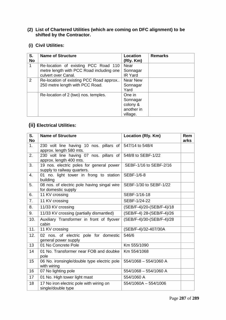
Page 287 of 289
(2) List of Chartered Utilities (which are coming on DFC alignment) to beshifted by the Contractor.
(i) Civil Utilities:
S.No
Name of Structure Location(Rly. Km)
Remarks
1 Re-location of existing PCC Road 110metre length with PCC Road including oneculvert over Canal.
NearSonnagarIR Yard
2 Re-location of existing PCC Road approx..250 metre length with PCC Road.
Near NewSonnagarYard
Re-location of 2 (two) nos. temples. One inSonnagarcolony &another invillage.
(ii) Electrical Utilities:
S.No
Name of Structure Location (Rly. Km) Remarks
1. 230 volt line having 10 nos. pillars ofapprox. length 580 mts.
547/14 to 548/4
2. 230 volt line having 07 nos. pillars ofapprox. length 400 mts.
548/8 to SEBF-1/22
3. 19 nos. electric poles for general powersupply to railway quarters.
SEBF-1/16 to SEBF-2/16
4. 01 no. light tower in frong to stationbuilding
SEBF-1/6-8
5. 08 nos. of electric pole having singal wirefor domestic supply
SEBF-1/30 to SEBF-1/22
6. 11 KV crossing SEBF-1/16-187. 11 KV crossing SEBF-1/24-228. 11/33 KV crossing (SEB/F-4)/20-(SEB/F-4)/189. 11/33 KV crossing (partially dismantled) (SEB/F-4) 28-(SEB/F-4)/2610. Auxiliary Transformer in front of flyover
cabin(SEB/F-4)/30-(SEB/F-4)/28
11. 11 KV crossing (SEB/F-4)/32-407/30A12. 02 nos. of electric pole for domestic
general power supply546/6
13 01 No Concrete Pole Km 555/109014 01 No. Transformer near FOB and doubke
poleKm 554/1068
15 06 No. ironsingle/double type electric polewith wiring
554/1068 – 554/1060 A
16 07 No lighting pole 554/1068 – 554/1060 A17 01 No. High tower light mast 554/1060 A18 17 No iron electric pole with wiring on
single/double type554/1060A – 554/1006

Page 288 of 289
19 17 No lighting mast 1044 A20 01 No High tower light mast 1044 A21 07 No single pole with 11 kv wiring 554/1008 – 554/1006 A22 01 No lighting pole 554/1006 A23 10 No single/double elelctric pole having
wiring554/8 – 553/29
24 02 No single/double electric pole 553/26
(3) Employer site data containing following data is enclosed (see separateBooklet Part- 4):(i) Plan and profile for the sections (Total 12 Sheets)
(a) Ch. 225.975 to 8460 - 5 Sheets
(b) Ch. 225.975 to 7270 - 2 sheets for UP line, 2 sheets for DN line &
2 sheets for Double line (UP&DN lines)
(c) Ch. 3.16 to 5.38 - 1 Sheet
(ii) GADs of RFO - 1 Sheet
(iii) GAD of Viaduct - 1 Sheet
(iv) GADs of Major Bridges - 2 Sheets
(v) GADs of Minor Bridges/RUBs - 35 Sheets
(vi) GADs of Burried Boxes - 2 Sheets
(vii) GAD of ROB - 1 Sheet
(viii) Yard Plans - 3 Sheets
(ix) GAD of Station Building - 2 Sheets
(x) GAD of quarter - 1 Sheet
(xi) Geotechnical Data - 1 Booklet
(xii) Traction earthing & Mast arrangement diagrams - 2 Sheets

Page 289 of 289
PART – 5
Price Schedules(See Separate Booklet)