bib.irb.hr€¦ · web viewfigure 3 shows 3d world with ... road-boundary detection and tracking...
TRANSCRIPT
Darko Babić, Mario Fiolić, Petr PrusaMOBILE LASER SCANNING METHOD FOR ROAD MARKINGS DATA COLLECTION
MOBILE LASER SCANNING METHOD FOR ROAD MARKINGS DATA
COLLECTION
Darko Babić Ph.D., Mario Fiolić mag.ing.traff.,
Faculty of Traffic and Transport Science
Vukelićeva 4, 10000 Zagreb, Croatia
Petr Prusa Ph.D.
University of Pardubice,
Jan Perner Transport Faculty
Studentská 95, 53210 Pardubice, Czech Republic
ABSTRACT
Recently, mobile laser scanning (MLS) has emerged as an efficient means to acquire massive
3D point clouds along urban road corridors for the several applications such as building
footprint reconstruction, facade modeling and road traffic inventories. A mobile laser
scanning (MLS) system allows direct collection of accurate 3D point information in
unprecedented detail at highway speeds and at less than traditional survey costs, which serves
the fast growing demands of transportation-related road surveying including road surface
geometry and road environment. This paper presents all the possibilities of mobile laser
scanning, especially identifying traffic signalization (traffic signs and road markings) using
the reflectivity information provided by the lidar sensors. As one type of road feature in traffic
management systems, road markings on paved roadways have important functions in
providing guidance and information to drivers and pedestrians.
Key words: mobile laser scanning, sensors, georeferenced video, traffic signalization
1. INTRODUCTION
Road administrators require more and more objective information’s about their network
and its surrounding environment for various purposes: disaster management, urban planning,
tourist guidance or simply road network management are some of the applications that
demand precise city modeling and interpretation. Industry also needs 3D reconstructions of
large areas; map providers for navigation systems now include semantic data in their bases
that can be interfaced in warning or driving assistance systems, mobile communication
development needs data for radio waves coverage analysis etc. Many companies and research
Darko Babić, Mario Fiolić, Petr PrusaMOBILE LASER SCANNING METHOD FOR ROAD MARKINGS DATA COLLECTION
labs have then focused in the last decade on the acquisition of mass data, developing many
acquisition platforms. Road network surveying generally implies aerial or satellite multi
spectral images processing but these approaches suffer from a lack of precision regarding road
geometry, although they provide a good classified overview of processed areas (Hatger and
Brenner, 2003) (Samadzadegan et al., 2009). Some research teams have therefore promoted
fusion between terrestrial and aerial data (Früh and Zakhor, 2004), requiring an existing
digital elevation map of the area to be processed.
City modeling is generally performed by means of vehicle borne lidar and cameras
(Zhao and Shibasaki, 2003) (Deng et al., 2004) (Boström et al., 2006); these works however
do not apply on road geometry or characterization. Some companies, cartographic institutes
and laboratories developed road dedicated vehicles, using inertial systems and 3D lidar
sensors in order to provide interpreted road environments. StreetMapper (Barber et al., 2008)
focus on elevation models, ICC (Talaya et al., 2004) use stereo and (Ishikawa et al., 2006)
monocular images for automatic processes, finally (Jaakkola et al., 2008) process lieder data
as image for extracted different kinds of road markings. (Goulette et al., 2006) only provide
automatic lieder data segmentation, performing classification of acquired scans in road, trees
or obstacles. The acquisition speed is nevertheless very low and the developed method cannot
deal with rural roads, as road extraction implies curbs.
2. SYSTEM FOR MOBILE LASER SCANNING
The car-mounted mobile laser scanning system (mobile lidar) has become a cost-effective
solution for capturing spatial data in complex urban areas at the street level quickly and
accurately. In particular, mobile lidar can acquire three-dimensional (3D) dense-points, which
enable easier building facade reconstruction, man-made object extraction, 3D city modeling,
street-scene modeling, and visualization than most other methods. In most cases, the
interpretation of 3D lidar point clouds is the first step of the above mentioned tasks.
In France1, they developed an acquisition vehicle for road surveying consisting in a very
precise positioning system, a CCD Color camera and 4 linear scanning sensors. The
positioning system consists in a Trimble Omnistar 8200-Hp GPS receiver, combined with an
Ixsea LandINS inertial measurement unit. This association delivers filtered 200 Hz GPS data
and can support GPS outages up to 300s while presenting very small drifts (0.005◦ for pitch
and roll, 0.01◦ for heading, 0.7m in the x-y plane and 0.5m for the z coordinate). Orientation
1 VIAMETRIS, Maison de la Technopole, 6 rue Leonard de Vinci, BP0119, 53001 Laval cedex, France, www.viametris.fr
Darko Babić, Mario Fiolić, Petr PrusaMOBILE LASER SCANNING METHOD FOR ROAD MARKINGS DATA COLLECTION
data are given in a North East Up reference, and GPS positions are translated in a metric
coordinates system using the adequate conic projection. As an imaging system, they use an
AVT Pike F-210C, a CCD color camera which provides Bayer filtered high definition images,
with a frame rate up to 30 Hz. Instead of a constant rate they decided to set the camera such as
it takes an image every n meters (n is generally set to 5 m, but can be adapted depending on
environment). Four SICK LMS-291 are installed on the roof of the vehicle (Figure 1). These
Laser range sensors provide 180◦ scans (with 0.5° angular resolution) up to 60 Hz scan rate.
Their sensing maximum range reaches 80 m with a 10 mm error and they also can output
reflectivity values (Figure 2). Three of them are looking to the ground with different
orientations, the fourth one being oriented towards the sky, in order to capture building
facades or trees (Figure 3). These sensors are controlled by the vehicle speed, stopping the
acquisition when the vehicle is stopped.
Figure 1 shows vehicle equipped with lidar and cameras while figure 2 shows “Front” and “Sky” lidar sensors cones of view
Source: Road extraction and environment interpretation from lidar sensors (Laurent Smadja, Jerome Ninot and Thomas Gavrilovic)
Figure 3 shows 3D world with reflectivity data
Source: Road extraction and environment interpretation from lidar sensors (Laurent Smadja, Jerome Ninot and Thomas Gavrilovic)

Darko Babić, Mario Fiolić, Petr PrusaMOBILE LASER SCANNING METHOD FOR ROAD MARKINGS DATA COLLECTION
Every data are acquired and time stamped using RTMaps software, on a single on-board
computer (Pentium IV, 2GHz) with adequate disk space.
3. PREVIOUS STUDIES
There are few road boundaries detection methods using only lidar range sensors. A well-
known paper (Kirchner and Heinrich, 1998)2 settles a horizontal lidar in order to detect
guardrails. A third polynomial road boundary model (with no first order term) is used to
approximate clothoid curve and an extended Kalman filter processes successive scans. The
Kalman prediction is performed using the steering angle and vehicle speed and the correction
stage assumes a radial error model. This approach inspired many other research teams despite
of being limited to roads presenting guardrails or curbs: another method uses a lidar oriented
towards the road and looks for curbs in successive scans (Wijesoma et al., 2004)3. They
assumed that each scan is ideally composed with different “flat” .phases: horizontal as the
sidewalks and the road, vertical as the curbs borders. A predicted point is computed from the
previous two range measurements on a frame, large prediction errors indicating phase
changes. The extracted segments are fitted by lines then further analyzed to provide potential
curbs.
The “flat road” approach has also been tested by Kim (et al., 2007.)4, that ensure a robot
positioning through a curb detection. Noticing that, due to the larger point density in front of
the range sensor, the most represented line is the road, they performed a Hough Transform on
the scan data. Curbs are then extracted as the extreme points surrounding the road. An
apparently faster approach uses histogram thresholding to detect curbs (Aufrere et al., 2003.)5,
from a side oriented lidar sensor, and via a modular algorithm. A maximum contrast approach
is then used as curbs present a different illumination than road and sidewalk. Different
approaches use a multi-layer lidar sensor. Dietmayer (et al., 2006.)6 presents two aspects of
2 Kirchner, A. and Heinrich, T., 1998. Model based detection on road boundaries with a laser scanner. In: Proceedings of the IEEE Intelligent Vehicles Symposium (IV’98), Stuttgart, Germany, pp. 93–98.3 Wijesoma,W. S., Kodagoda, K. R. S. and Balasuriya, A. P., 2004. Road-boundary detection and tracking using ladar sensing. IEEE Transactions on Robotics and Automation 20(3), pp. 456–464.4 Kim, S.-H., Roh, C.-W., Kang, S.-C. and Park, M.-Y., 2007. Outdoor navigation of a mobile robot using differential gps and curb detection. In: Proceedings of International Conference on Robotics and Automation, Roma, Italy, pp. (on CD–ROM).5 Aufrere, R., Mertz, C. and Thorpe, C., 2003. Multiple sensor fusion for detecting location of curbs, walls, and barriers. In: Proceedings of the IEEE Intelligent Vehicles Symposium (IV’03), Colombus, OH, USA, pp. (on CD–ROM).6 Dietmayer, K., K¨ampchen, N., F¨urstenberg, K. and Kibbel, J., 2006. Roadway detection and lane detection using multilayer laserscanner. In: Proceedings of International Conference on Robotics and Automation, Orlando, FL, USA, pp. (on CD - ROM).

Darko Babić, Mario Fiolić, Petr PrusaMOBILE LASER SCANNING METHOD FOR ROAD MARKINGS DATA COLLECTION
road detection with an 6 layers lidar, two of them being dedicated to lane following; this part
is performed by correctly setting the sensor sensitivity, as asphalt present a small reflectivity
compared to road markings. Besides, they present an object detection by segmenting each
scan with an adaptive threshold, the classification being performed through the object
dynamic analysis (Sparbert et al., 2001). These obstacles are further eliminated so as not to
disturb the road extraction process. Assuming an equal curvature for left and right sides and
considering several curvature hypotheses, the road is extracted by finding the solution that
minimizes the number of candidates between the road boundaries.
The authors of “Road extraction and environment interpretation from lidar sensors”7
finally classify the road type from the estimated width, and discard unlikely object
classifications. Starting from the observations they developed a two-step road detection
algorithm which processes the front lidar scans. This algorithm is based on different uses of
RanSaC method (Fischler and Bolles, 1981)8. Extracted road boarders and centers are then
processed and provide useful information about road geometry, such as road width or road
curvature.
Also, test of MLS (mobile laser scanning) data was carried out in survey area of Xiamen
Island, a part of the City of Xiamen, which is a major city on the southeast coast of China.
The data9 were acquired on 23 April 2012 by a RIEGL VMX-450 MLS system, which was
smoothly integrated with two RIEGL VQ-450 scanners with laser pulse repetition rates (PRR)
up to 550 kHz, an IMU/GNSS unit, a wheel-mounted Distance Measurement Indictor (DMI),
and four high-resolution cameras. This integrated set of the VMX-450 MLS system was
mounted on the roof of a vehicle travelling at an average speed of 50 km/h. The two RIEGL
VQ-450 laser scanners were symmetrically configured on the left and right sides, pointing
toward the rear of the vehicle at a heading angle of approximately145°.
4. IDENTIFYING OBJECTS TO SCAN
In general, off-ground urban objects can be divided into man-made and nature objects,
whereas man-made objects are referred to a variety of buildings, traffic facilities, power lines,
poles, and cars, while nature objects are referred to vegetation. The approach for identifying
7 Smadja, L., Ninot, J. and Gavrilovic, T.; ROAD EXTRACTION AND ENVIRONMENT INTERPRETATION FROM LIDAR SENSORS; VIAMETRIS, Maison de la Technopole, 6 rue Leonard de Vinci, BP0119, 53001 Laval cedex, France, www.viametris.fr8 Fischler, M. A. and Bolles, R. C., 1981. Random sample consensus: A paradigm for model fitting with applications to image analysis and automated cartography. Communications of the ACM 24(6), pp. 381–395.9 Haiyan Guan , Jonathan Li, Yongtao Yu, Cheng Wang, Michael Chapman , Bisheng Yang ; Using mobile laser scanning data for automated extraction of road markings.
Darko Babić, Mario Fiolić, Petr PrusaMOBILE LASER SCANNING METHOD FOR ROAD MARKINGS DATA COLLECTION
man-made objects from natural objects consists of three steps: the preprocessing; the
extraction of seed points for man-made objects; and the extraction of man-made objects
In the preprocessing, ground points are detected by analyzing the height histogram (Yao
et al., 201010) and are further delivered to a surface fitting algorithm (Gridfit Algorithm) to
obtain a ground level raster. The vertical distance of each point to the ground level is
calculated as the height above the ground level (AGL - altitude above ground level). Man-
made objects can be separated into three classes according to the AGL height: 1. Fences or
cars whose AGL heights are less than two meters; 2. Buildings whose AGL heights are larger
than two meters; and 3. Power lines hanging in the air and having the lowest AGL height of
five meters. In the vertical dimension, different objects could co-exist. For instance, a vehicle
might be parked under a tree, while branches of a tree grow over the fence. This leads to error
detection when using the method of projecting 3D points on a horizontal accumulator used in
Hammoudi (2009)11. To overcome such deficiency, the off-ground points of MLS data are
divided into three layers according to the AGL height.
The second step aims to extracting seed points of man-made objects in each height layer.
The ideal is rooted in the fact that man-made objects feature geometric regularity like vertical
planes, while vegetation reveals a huge diversity of shapes and point distribution. If 3D points
are projected onto 2D horizontal plane, the position where man-made objects are located will
indicate a large accumulation density.
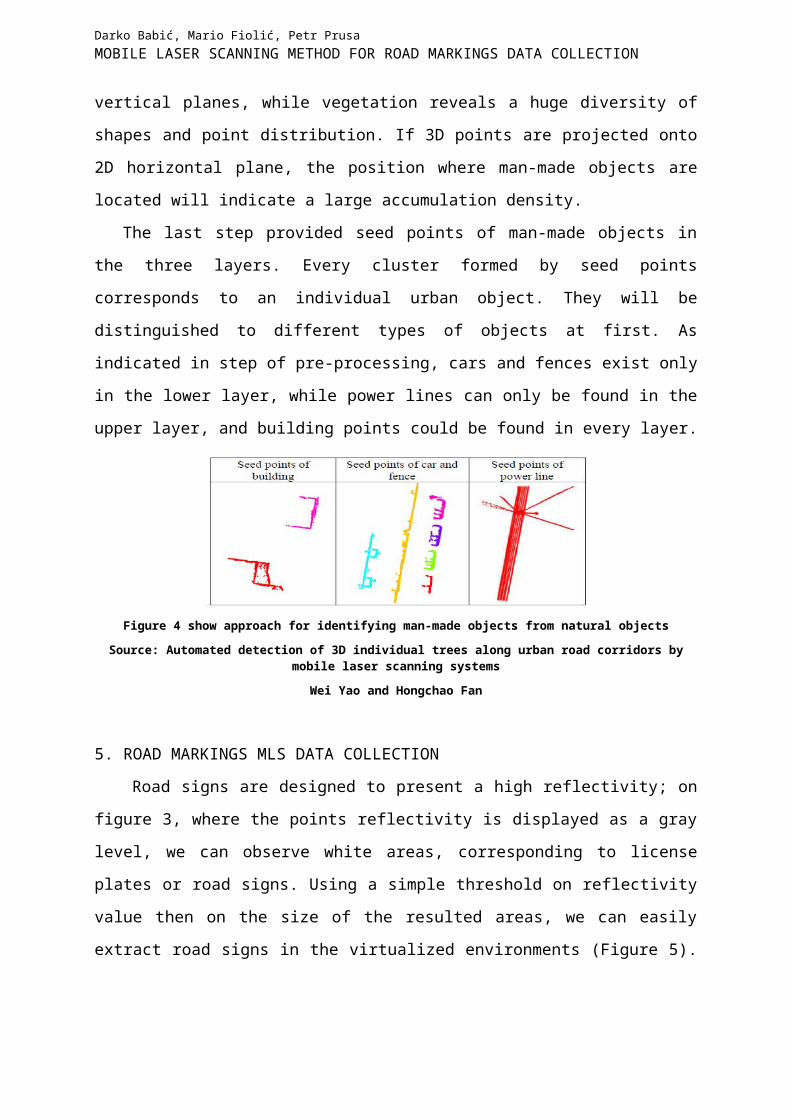
The last step provided seed points of man-made objects in the three layers. Every cluster
formed by seed points corresponds to an individual urban object. They will be distinguished
to different types of objects at first. As indicated in step of pre-processing, cars and fences
exist only in the lower layer, while power lines can only be found in the upper layer, and
building points could be found in every layer.
Figure 4 show approach for identifying man-made objects from natural objects
10Yao, W., Hinz, S., Stilla, U., 2010. Automatic Vehicle Extraction from Airborne LiDAR Data of Urban Areas aided by Geodesic Morphology. Pattern Recognition Letters, Vol.31, no.10, pp. 1100-1108.11 Hammoudi, K., Dornaika F. and Paparoditis N. 2009. Extracting building footprints from 3D point clouds using terrestrial laser scanning at street level. In: Stilla U., Rottensteiner F., Paparoditis N. (Eds) CMRT09. IAPRS, Vol. XXXVIII, Part3/W4, Paris, France, 3-4 September, 2009.

Darko Babić, Mario Fiolić, Petr PrusaMOBILE LASER SCANNING METHOD FOR ROAD MARKINGS DATA COLLECTION
Source: Automated detection of 3D individual trees along urban road corridors by mobile laser scanning systems
Wei Yao and Hongchao Fan
5. ROAD MARKINGS MLS DATA COLLECTION
Road signs are designed to present a high reflectivity; on figure 3, where the points
reflectivity is displayed as a gray level, we can observe white areas, corresponding to license
plates or road signs. Using a simple threshold on reflectivity value then on the size of the
resulted areas, we can easily extract road signs in the virtualized environments (Figure 5). The
sign areas can further be projected on image in order to perform optical fine extraction and
recognition.
Figure 5 shows road signs displayed in blue and road markings displayed in white color (mobile laser scanning)
Source: Road extraction and environment interpretation from lidar sensors (Laurent Smadja, Jerome Ninot and Thomas Gavrilovic)
With a correctly extracted road and using the reflectivity data, we can also extract road
markings trough a simple thresholding. As claimed (Dietmayer et al., 200612), asphalt presents
a much lower reflectivity than road markings so that threshold determination is quite easy.
Nevertheless, this approach can in some cases be less robust than image processing methods,
as it highly depends on marking reflectivity, which is faster deteriorated than white painting.
In the most cases, road markings show linear features and have dimensions of known width
and length. To extract road markings from the point clouds filtered by two-step filter operator,
a georeferenced reflectance intensity image was firstly generated. Then, the 4-connected
regions of the georeferenced intensity image were labeled for detecting the regions of road
markings. For each 4-connected region, a set of parameters namely, the area of each 4-
connected region, the area, length, and width of the minimum bounding box of each 4-
connected region, and the ellipse with the same second-moments as the 4-connected region 12 Dietmayer, K., K¨ampchen, N., F¨urstenberg, K. and Kibbel, J., 2006. Roadway detection and lane detection using multilayer laserscanner. In: Proceedings of International Conference on Robotics and Automation, Orlando, FL, USA, pp. (on CD - ROM).
Darko Babić, Mario Fiolić, Petr PrusaMOBILE LASER SCANNING METHOD FOR ROAD MARKINGS DATA COLLECTION
were calculated, respectively. Figure 6 shows segmentation of the point clouds of a road. An
interpolation method is first used to generate a georeferenced feature image of the point cloud
which helps to isolate the points of road surfaces. Then, an algorithm is used to separate these
points within a range according to their strength of reflection. The separated points are further
segmented to remove non-road points based on height threshold. Finally, the outlines of road
markings are extracted (we get the cadastral of road markings or traffic signs) the segment
points using the semantic knowledge of road markings.
Figure 6 shows segmentation of the point clouds of a road: a) Original point clouds; b) Filtered result by reflectance intensity; c) Filtered result by height
Source: Automated extraction of road markings from mobile lidar point clouds
B Yang, L Fang, Q Li, J Li
6. CONCLUSION
Automated restitution methods for object acquisition have gained more and more
importance in the last years. Mobile laser scanning (MLS) is the latest approach towards fast
and cost-efficient acquisition of 3-dimensional spatial data. Scanning objects using a 3D-laser
scanner operating in a 2D-line scan mode from various different runs and scan directions
provides valuable scan data for determining the angular alignment between inertial
measurement unit and laser scanner. Field data is presented demonstrating the final accuracy
of the calibration and the high quality of the point cloud acquired during an MLS campaign.
The mobile laser scanning technology achieved the best performance evaluation, where a
detailed data analysis, data collection, mobile laser missions, modelling and interpretation,
system geometrical corrections for the location and orientation also have been conducted.
Next to automatic image matching, laser scanning, often also referred to as LiDAR (light

Darko Babić, Mario Fiolić, Petr PrusaMOBILE LASER SCANNING METHOD FOR ROAD MARKINGS DATA COLLECTION
detection and ranging), has revolutionized 3D data acquisition for both, topographic as well as
close range objects. In contrast to the “classical” manual data acquisition techniques, like
terrestrial surveying and analytical photogrammetry, which require a manual interpretation in
order to derive a representation of the sensed objects, these new automatic recording methods
allow an automated dense sampling of the object surface within a short time. Mobile lidar
technology is a widely accepted tool providing exceptionally efficient data collection of high
accuracy for various surveying applications. Prior conducting the performance evaluation, the
research investigates the mobile laser behavior and recognition capabilities with respect to
polyethylene city infrastructure materials.
AcknowledgementThe Ministry of Education, Youth and Sports of the Czech Republic, Project
POSTDOK, CZ.1.07/2.3.00/30.0021 “Enhancement of R&D Pools of Excellence at the
University of Pardubice“, financially supported this work.
7. LITERATURE
[1] Yang, B., Fang, L., Li, Q., Li, J.: Automated extraction of road markings from mobile
LiDAR point clouds, Photogrammetric engineering & remote sensing, April 2012.
[2] Guan, H., Li, J., Yu, Y., Wang, C., Chapman, M., Yang B.: Using mobile laser scanning
data for automated extraction of road markings, ISPRS Journal of Photogrammetry and
Remote Sensing, November 2013.
[3] Smadja, L., Ninot, J., Gavrilovic, T.: Road extraction and environment interpretation
from lidar, Paparoditis N., Pierrot-Deseilligny M., Mallet C., Tournaire O. (Eds),
IAPRS, Vol. XXXVIII, Part 3A – Saint-Mandé, France, September 1-3, 2010.
SENSORS
[4] Yaoa, W., Fanb, H.: Automated detection of 3D individual trees along urban road
corridors by mobile laser scanning systems, International Symposium on Mobile
Mapping Technology (MMT) 2013, Tainan, Taiwan; 05/2013.
[5] Rieger, P., Studnicka, N., Pfennigbauer, M.: Boresight alignment method for mobile
laser scanning systems, Journal of Applied Geodesy. Volume 4, June 2010.
[6] Kirchner, A. and Heinrich, T., 1998. Model based detection on road boundaries with a
laser scanner. In: Proceedings of the IEEE Intelligent Vehicles Symposium (IV’98),
Stuttgart, Germany, pp. 93–98.
Darko Babić, Mario Fiolić, Petr PrusaMOBILE LASER SCANNING METHOD FOR ROAD MARKINGS DATA COLLECTION
[7] Wijesoma,W. S., Kodagoda, K. R. S. and Balasuriya, A. P., 2004. Road-boundary
detection and tracking using ladar sensing. IEEE Transactions on Robotics and
Automation 20(3), pp. 456–464.
[8] Kim, S.-H., Roh, C.-W., Kang, S.-C. and Park, M.-Y., 2007. Outdoor navigation of a
mobile robot using differential gps and curb detection. In: Proceedings of International
Conference on Robotics and Automation, Roma, Italy, pp. (on CD–ROM).
[9] Aufrere, R., Mertz, C. and Thorpe, C., 2003. Multiple sensor fusion for detecting
location of curbs, walls, and barriers. In: Proceedings of the IEEE Intelligent Vehicles
Symposium (IV’03), Colombus, OH, USA, pp. (on CD–ROM).
[10] Dietmayer, K., K¨ampchen, N., F¨urstenberg, K. and Kibbel, J., 2006. Roadway
detection and lane detection using multilayer laserscanner. In: Proceedings of
International Conference on Robotics and Automation, Orlando, FL, USA, pp. (on CD -
ROM).
[11] Smadja, L., Ninot, J. and Gavrilovic, T.; ROAD EXTRACTION AND
ENVIRONMENT INTERPRETATION FROM LIDAR SENSORS; VIAMETRIS,
Maison de la Technopole, 6 rue Leonard de Vinci, BP0119, 53001 Laval cedex, France,
www.viametris.fr
[12] Fischler, M. A. and Bolles, R. C., 1981. Random sample consensus: A paradigm for
model fitting with applications to image analysis and automated cartography.
Communications of the ACM 24(6), pp. 381–395.
[13] Haiyan Guan , Jonathan Li, Yongtao Yu, Cheng Wang, Michael Chapman , Bisheng
Yang ; Using mobile laser scanning data for automated extraction of road markings.
[14] Yao, W., Hinz, S., Stilla, U., 2010. Automatic Vehicle Extraction from Airborne
LiDAR Data of Urban Areas aided by Geodesic Morphology. Pattern Recognition
Letters, Vol.31, no.10, pp. 1100-1108.
[15] Hammoudi, K., Dornaika F. and Paparoditis N. 2009. Extracting building footprints
from 3D point clouds using terrestrial laser scanning at street level. In: Stilla U.,
Rottensteiner F., Paparoditis N. (Eds) CMRT09. IAPRS, Vol. XXXVIII, Part3/W4,
Paris, France, 3-4 September, 2009.
[16] Dietmayer, K., K¨ampchen, N., F¨urstenberg, K. and Kibbel, J., 2006. Roadway
detection and lane detection using multilayer laserscanner. In: Proceedings of
International Conference on Robotics and Automation, Orlando, FL, USA, pp. (on CD -
ROM).