biaxial orientation of poly(vinyl chloride) compounds part ... · pdf filechloride) compounds...
TRANSCRIPT

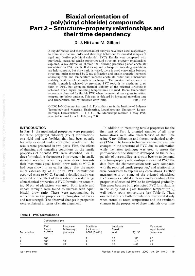
Loughborough UniversityInstitutional Repository
Biaxial orientation ofpoly(vinyl chloride)compounds Part 2�Structure�property
relationships and their timedependency
This item was submitted to Loughborough University's Institutional Repositoryby the/an author.
Citation: HITT, D.J. and GILBERT, M., 2000. Biaxial orientation of poly(vinylchloride) compounds Part 2 �Structure�property relationships and their timedependency. Plastics, Rubber and Composites, 29 (3), pp. 149 - 160
Additional Information:
• This article was published in the journal, Plastics, Rubberand Composites [ c© Maney Publishing] and is available at:http://www.ingentaconnect.com/content/maney/prc
Metadata Record: https://dspace.lboro.ac.uk/2134/4507
Version: Published
Publisher: c© Maney Publishing
Please cite the published version.

This item was submitted to Loughborough’s Institutional Repository (https://dspace.lboro.ac.uk/) by the author and is made available under the
following Creative Commons Licence conditions.
For the full text of this licence, please go to: http://creativecommons.org/licenses/by-nc-nd/2.5/
Pub
lishe
d by
Man
ey P
ublis
hing
(c)
IOM
Com
mun
icat
ions
Ltd
Biaxial orientation ofpoly(vinyl chloride) compounds
Part 2 – Structure–property relationships andtheir time dependency
D. J. Hitt and M. Gilbert
X-ray diffraction and thermomechanical analysis have been used, respectively,to examine structural order and shrinkage behaviour for oriented samples ofrigid and flexible poly(vinyl chloride) (PVC). Results were compared withpreviously measured tensile properties and structure–property relationshipsexplored. X-ray diffraction showed that drawing produces planar crystalliteorientation in PVC sheets. If drawing and subsequent annealing conditionsare held constant, but draw ratio is varied, there is good correlation betweenstructural order measured by X-ray diffraction and tensile strength. Increasedannealing time and temperature improve crystallite order and dimensionalstability, while tensile strength is unchanged. The greatest enhancement intensile strength is achieved by stretching PVC towards its maximum drawratio at 90°C, but optimum thermal stability of the oriented structure isachieved when higher annealing temperatures are used. Room temperaturerecovery is observed for flexible PVC when the material has a glass transitiontemperature below ambient. This can be delayed by increased annealing timeand temperature, and by increased draw ratio. PRC/1448
© 2000 IoM Communications Ltd. The authors are in the Institute of PolymerTechnology and Materials Engineering, Loughborough University, Lough-borough, Leicestershire LE11 3TU, UK. Manuscript received 1 May 1998;accepted in final form 11 February 2000.
INTRODUCTION In addition to measuring tensile properties for thefirst part of Part 1, oriented samples of all threeIn Part 11 the mechanical properties were presented
for three poly(vinyl chloride) (PVC) formulations, formulations were also characterised at that timeusing X-ray diffraction and thermomechanical analy-one rigid and two flexibles, that had been equally
biaxially oriented under controlled conditions. The sis (TMA). The former technique was used to examinechanges in the structure of PVC due to orientationresults were presented in two parts. First, the effects
of drawing and annealing conditions on the tensile while the latter technique was used to assess thepermanence of the structure developed. As the princi-properties of oriented PVC were described. For all
three formulations the greatest improvement in tensile pal aim of these studies has always been to understandstructure–property relationships in oriented PVC, thestrength occurred when they were drawn towards
their maximum equal biaxial draw ratio at 90°C. It data from the characterisation tests were comparedwith the reported tensile properties,1 and relationshipshad been shown in an earlier study2 that the maxi-
mum extensibility of all three PVC formulations were considered to explain any correlations. Furthermeasurements on some of the oriented plasticisedoccurred close to 90°C. Second, a detailed study was
reported on the effect of draw ratio on a wider range PVC samples enabled a clearer understanding of theproperties of oriented PVC to be developed gradually.of mechanical properties. A PVC formulation contain-
ing 30 phr of plasticiser was used. Both tensile and This arose because both plasticised PVC formulationsin the study had a glass transition temperature Tgimpact strength were found to increase with equal
biaxial draw ratio. These were accompanied by well below room temperature (see Table 1). Thus,oriented sheets of both formulations recovered slowlyreductions in the properties of elongation at break
and tear strength. The observed changes in properties when stored at room temperature and the resultantchanges in the properties of these materials over timewere explained in terms of chain alignment.
Table 1 PVC formulations
Components, phr
PVC Plasticiser Stabiliser Lubricant MaximumEvipol Di-iso-octyl Lankromark Stearic equal biaxial
Formulation SH7020 phthalate LC68 (Ba–Cd) acid Tg, °C draw ratio
1 100 ... 2 0·5 80 2·02 100 30 2 0·5 −3 2·13 100 70 2 0·5 −41 2·4
Plastics, Rubber and Composites 2000 Vol. 29 No. 3 149ISSN 1465–8011

Pub
lishe
d by
Man
ey P
ublis
hing
(c)
IOM
Com
mun
icat
ions
Ltd
150 Hitt and Gilbert Biaxial orientation of poly(vinyl chloride) compounds: Part 2
has proved extremely valuable in relating structureto properties in oriented PVC.
In the present paper the X-ray diffraction and TMAdata obtained from the oriented sheets at the time ofPart 1 are presented, followed by similar data for theoriented plasticised PVC sheets that have been gath-ered over time. In the discussion of these results,initial proposals with regard to structure–propertyrelationships are included so that the subsequentrefinement of ideas due to the time dependent datacan be seen.
EXPERIMENTAL
1 Typical X-ray diffraction patterns for unorientedPreparation of oriented PVC sheetsand oriented PVC samples; pattern for orientedCompression moulded sheets of the three formu-sample has been displaced on vertical axislations used in this study (Table 1) were prepared by
the method described in Part 1. Biaxial stretchingCharacterisation of oriented structuresequipment (BASE)3 was used to produce equallyDescriptions are given below of how the techniquesbiaxially oriented samples under controlled con-of X-ray diffraction and TMA have been applied inditions. The BASE has been designed as an attach-this study. Appropriate examples are used to illustratement for an Instron tensile testing machine and hasthe techniques.a stretching head located within a temperature con-
trolled environmental cabinet. The movement of the X-ray diffractioncrosshead of the Instron can be programmed pre- Commercial PVC is typically 55% syndiotactic andcisely. This facility was used to drive the two perpen- both unplasticised and plasticised PVC are known todicular draw rods of the stretching head, one directly have about 5–10% crystallinity.4 Typical reflectanceand the other via a hydraulic link, simultaneously at mode X-ray diffraction patterns are shown in Fig. 1constant speeds. Samples are attached to the stretch- for oriented and unoriented samples. In both patternsing head by means of four sets of ten grips which there is a broad underlying peak due to scatteringmove apart proportionately as the head opens. After from the amorphous regions of the polymer. Thecontrolled stretching, samples were annealed under peaks labelled A, B, and C are of primary interest asrestraint in the environmental cabinet of the BASE they arise from scattering by crystalline regions.4 Theand then cooled to ambient temperature before being unit cell of PVC is known to be orthorhombic5 withreleased from the grips. All samples were marked the peak at 2h#16·5° (A) corresponding to the (200)with a precise grid of 100 squares of 10×10 mm reflection, that at 2h#18·5° (B) to the (110) reflec-before stretching so that draw ratios of oriented sheets tion, and that at 2h#24° (C) to reflections fromcould be determined accurately at any time after (201), (210), and (111) planes. Traces of this type arestretching. The draw conditions of rate, ratio, and frequently used for measurements of crystallinity intemperature and the subsequent annealing conditions PVC.4 For this purpose, a trace for an amorphousof temperature and time were varied so that their (quenched) sample is superimposed on that of theeffects on oriented PVC could be determined. The sample of interest, and crystallinity is calculated byrange of values for each of these variables is con- measuring areas or intensities corresponding to crys-strained by either the extensibility of PVC or by the talline peaks and comparing these with the area orspecifications of the BASE. These limitations have intensity of the total diffraction pattern. A similarbeen discussed in previous work.1,3 method has been used previously for the analysis of
oriented PVC samples.6 However, in this workchanges in individual peaks have been monitored.
Tensile properties This can be more informative since crystallite align-The tensile properties reported in Part 1 are included ment is of particular interest. Peaks A and B relatein the present paper to enable comparisons to bemade readily with the results of X-ray and TMA Table 2 Tensile properties of undrawn andstudies. Table 2 shows the tensile properties of biaxially oriented PVC*undrawn samples of each formulation along with
Tensile propertiesproperties for oriented sheets produced under theconditions shown. (The consistency of the measured s
B, MPa e
B, %
properties can be seen from the standard deviations Plasticiser,phr Undrawn Drawn Undrawn Drawngiven in the table.) As in the previous work, to simplify
the presentation of results in this paper, the tensile0 55·4 (3·4) 79·3 (2·9) 213 (22) 111 (10)
properties of oriented sheets are expressed as property 30 29·8 (1·4) 51·9 (2·9) 331 (22) 271 (6)ratios, i.e. the values of stress at break sB and elong- 70 15·3 (0·4) 23·2 (1·1) 613 (13) 380 (19)ation at break eB for a drawn sheet are divided by
* Stretching conditions: draw 100 mm min−1 (given erro-the respective values of sB and eB for the correspond- neously as 10 mm min−1 in Part 1) and 90°C to 1·5X; anneal 10
min at 90°C; standard deviations given in parentheses.ing undrawn material.
Plastics, Rubber and Composites 2000 Vol. 29 No. 3

Pub
lishe
d by
Man
ey P
ublis
hing
(c)
IOM
Com
mun
icat
ions
Ltd
Hitt and Gilbert Biaxial orientation of poly(vinyl chloride) compounds: Part 2 151
to planes that are parallel to the chain axis. Peak Crelates to several sets of planes and increases inintensity when the amount of three-dimensional crys-tallinity increases.7 However, changes in this peakcannot be related to specific crystal alignment.
X-ray diffraction patterns were obtained using aJEOL DX-GE-2S generator fitted with a verticalgoniometer of type DX-GO-S. The X-ray source wasNi filtered Cu K
aradiation and was operated at 40 kV
and 30 mA. Flat samples were placed on the goni-ometer stage and reflectance mode measurements ofthe X-ray intensity were obtained over the 2h rangeof 10–50°.
Each time an X-ray diffraction pattern wasobtained from an oriented sample a reference patternwas measured for an unstretched sample of the sameformulation. When such corresponding pairs of pat-terns were compared, several consistent featuresbecame apparent that were applicable to all PVCformulations. These are illustrated by the pair ofpatterns shown in Fig. 1:
(i) at 2h angles>35°, very similar intensities arefound in both patterns as only amorphousscattering occurs at these angles
(ii ) orientation does not change the C peak sig-nificantly
(iii) the A and B peak intensities increase due toorientation with the change in the former beingmore dramatic
(a)
(b)
(iv) the B peak is generally slightly higher than the 2 X-ray diffraction patterns for a unoriented andA peak for unoriented samples. b oriented samples of each formulation, drawn
The significant changes in the A peak can be explained and annealed under conditions given in Table 2in terms of the structural changes occurring on draw-ing. They show that the number of (200) planes lying
for the patterns of Fig. 1. The change in A peakin the plane of the film has increased. This can be
intensity is then expressed in terms of the ‘A peakcaused either by realignment of existing crystals in
ratio’. This ratio provides a measure of structuralthe plane of the film or by a stress induced increase
order in the oriented sample relative to thein crystallinity. Recent structural studies have shown
unstretched state.that both of these effects can occur.8 However, the
Figure 2a and b shows X-ray diffraction patternstwo diffraction patterns presented in Fig. 1 show that
for unstretched mouldings and oriented samples ofthe area of the C peak is almost unaffected by biaxial
each formulation. The oriented samples were pro-drawing, thereby indicating that the increase in crys-
duced under the conditions given in Table 2. Thetallinity is quite small. The increase in the A peak
baselines generated from the patterns of Fig. 2a havecorresponds to an increased alignment of the b–c
been added to Fig. 2b. The calculated A peak ratiosplane of the crystals in the plane of the film, which
were 1·54, 1·44, and 1·17, respectively for the formu-means that the a axis is aligned normal to the plane
lations containing 0, 30, and 70 phr of plasticiser.of the film, as the unit cell of PVC is orthorhombic.
Thus, while X-ray intensity for both unstretched andThe alignment of the (110) planes is also increased
oriented samples increases with increasing plasticiserby biaxial drawing, but to a smaller extent. These
content, the A peak ratio decreases. X-ray intensityplanes are at an angle of 63° to the (200) planes, so
is seen to increase with plasticiser content becausethat they can be detected only when the b axis tilts
the plasticiser swells the amorphous regions of theout of the plane of the film, while the c axis remains
polymer.in the plane of biaxial drawing.
TMAMeasurement of the A peak was used to assess theIt is well known that oriented polymer productsinfluence of biaxial orientation on structural order.shrink upon heating. To assess this behaviour, TMAThe similarity between the patterns for an orientedcan be used to measure changes in samples of orientedsample and its corresponding unstretched materialmaterial as a function of temperature at a controlled(at 2h>35° ) was employed to generate a referenceheating rate. Two methods have been reported in thebaseline to measure the change in A peak intensity.literature: measurement of retractive force9–11 andFor the unstretched material, a line was drawn con-measurement of dimensional change.12–14 In thenecting the X-ray intensity at 2h=50° to that atformer, a sample is clamped so that its length is held2h=35° and extended to the low angle end of theconstant during heating. A load cell is used to measurepattern. A line of the same slope was then drawnthe retractive force exerted by the sample as it triesbelow the pattern of the oriented sample starting
from the intensity at 2h=50°. These lines are shown to shrink. In the second method a sample of known
Plastics, Rubber and Composites 2000 Vol. 29 No. 3

Pub
lishe
d by
Man
ey P
ublis
hing
(c)
IOM
Com
mun
icat
ions
Ltd
152 Hitt and Gilbert Biaxial orientation of poly(vinyl chloride) compounds: Part 2
(a)
(A)
(C)
(B)
(b)
(A)
(C)
(B)
draw ratio: a A 1·5; a B 1·7; a C 1·9; b A 1·5; b B 2·0; b C 2·4
3 Pairs of TMA curves of dimensional change v. temperature for equally biaxially oriented samples of arigid PVC and b 70 phr plasticised PVC stretched at 90?C to different draw ratios
length is held between a fixed grip and a free moving formulations. Second, as the rigid formulation has aTg of 80°C (Table 1) TMA curves of this materialgrip. A sensitive probe attached to the free moving
grip is able to follow dimensional change in the initially show a steady slope due to expansion untilTg is approached, where the onset of shrinkage causessample during heating. The two methods have been
applied to oriented rigid PVC.9,12 In both papers it the curves to deviate from the expansion slope. Forrigid PVC the shrinkage onset temperature can bewas reported that changes in oriented samples
occurred only as the Tg of the PVC formulation under taken as the temperature at which the shrinkage curvebegins to deviate from the extended initial expansiontest was approached.
In this work, a Mettler TMA40 Thermomechanical slope ( line labelled ‘EXP’ in Fig. 3a). Third, the 70 phrplasticised formulation begins to shrink appreciablyAnalyser fitted with a film and fibre attachment was
used to measure dimensional change in oriented soon after heating has commenced, Fig. 3b, becauseits Tg is well below room temperature. As orientedsamples. The attachment holds a narrow strip of
material in its grips leaving a precise sample length products of such materials recover slowly when storedat room temperature their shrinkage onset temper-of 10 mm exposed to heating. A controlled heating
rate of 10 K min−1 was employed and a weight of 1 g atures are also below room temperature. In view ofthis it would be invalid to derive shrinkage onsetwas applied to the probe attached to the free
moving grip. temperatures from TMA curves obtained from theoriented plasticised samples of this study.As this study concerns equal biaxial stretching it
was considered appropriate to test two samples from To enable a general comparison of the shrinkagebehaviour in this study the pairs of TMA curves foreach oriented sheet: one cut parallel to the vertical
draw direction of the BASE3 and one perpendicular each oriented sheet have been combined to generatea single ‘area shrinkage’ curve, using the followingto it. Figure 3a and b shows typical TMA curves of
dimensional change against temperature for perpen- method based on Fig. 4. The two TMA samples definea post-stretch area of 100 mm2. If the equal biaxialdicular pairs of samples of rigid PVC and of 70 phr
plasticised PVC, respectively, stretched at 90°C to draw ratio of the sheet is l then the original area insquare millimetres defined by the two samples priordifferent draw ratios. A number of important points
can be drawn from these figures. First, the expected to stretching is 100/l2. Thus the maximum recoverablearea through shrinkage is 100(1−1/l2). If at a givenbehaviour that samples with higher draw ratios will
shrink more ultimately can be clearly seen for both temperature, the measured probe displacements for a
Plastics, Rubber and Composites 2000 Vol. 29 No. 3

Pub
lishe
d by
Man
ey P
ublis
hing
(c)
IOM
Com
mun
icat
ions
Ltd
Hitt and Gilbert Biaxial orientation of poly(vinyl chloride) compounds: Part 2 153
has become established and the difference betweenthe 5 and 50% shrinkage temperatures is a goodindicator of the slope of the curve once shrinkagehas become established. Table 2 shows the expectedresults that equal biaxial orientation significantlyenhances the tensile strength of both rigid and flexiblePVC while reducing elongation at break. It appearsthat under the same stretching conditions, the A peakratio is reduced by the addition of plasticiser. Theinfluence of Tg on the shrinkage behaviour of rigidPVC is very apparent. While the shrinkage onsettemperature is 62°C it is only when the Tg of thematerial, 80°C, is exceeded that appreciable shrinkageoccurs. The relatively poor dimensional stability ofthe 30 phr plasticised PVC formulation is well illus-trated in Fig. 6.
Tables similar to Table 3 are presented to show theeffects of the stretching variables: draw ratio, drawrate, draw temperature, annealing temperature, andannealing time. For each variable efforts were made,wherever practical, to maintain the same time intervalbetween the preparation of the oriented sheets of agiven formulation and any subsequent property
4 Basis for calculating area shrinkage for equally measurements. In addition, because oriented sheetsbiaxially oriented sheet
of plasticised PVC recover over time, the draw ratiosgiven in the tables were those taken at the time the
pair of samples are S1 (mm) and S2 (mm), then it can properties were measured and not those achievedbe shown that the area shrinkage of the sample AS as immediately after stretching. The precise grid markeda percentage of the maximum recoverable area is on each sheet enabled draw ratios to be determined
accurately at any time.AS (%)=[10(S1+S2 )−S1S2]/(1−1/l2)
This equation can be used to calculate AS as a Effects due to stretching conditionsfunction of temperature. Presentation of TMA data
Draw ratioin this way has a number of advantages. First, byAll three formulations have a maximum equal biaxialdefinition an AS of 100% means the oriented sampledraw ratio at 90°C.1 These are given in Table 1has returned to its original dimensions, and second,and refer to sheets immediately after removal fromwhen draw ratio is the variable, shrinkage behaviourthe BASE. The effect of drawing each formulationcan be compared on the same scale. The latter is verytowards its maximum at 90°C can be seen in Table 4.well illustrated by Fig. 5a and b which shows, respect-There is a significant improvement in tensile strengthively, the calculated area shrinkage curves for thewith increasing draw ratio, for example, the strengthpairs of samples in Fig. 3a and b.of the plasticised formulations is increased by around65–70% at a draw ratio of 2·0. This increase in
RESULTS mechanical strength is matched by a similarly signifi-Table 3 compares the properties of oriented sheets of cant increase in X-ray A peak ratio. Draw ratio haseach formulation produced under the same con- little effect on the shrinkage onset temperature of theditions. Tensile property ratios were calculated from rigid formulation or upon the area shrinkage temper-the data in Table 2, X-ray A peak ratios were deter- atures of each formulation. The latter is well illus-mined from Fig. 2. Figure 6 shows the area shrinkage trated by the area shrinkage curves of Fig. 5a and b.curves for each formulation from which the shrinkage
Draw ratetemperatures given in Table 3 were derived. The 5Table 5 compares the properties of pairs of samplesand 50% shrinkage temperatures are convenientof each formulation that were biaxially oriented atmeans of comparing shrinkage behaviour. The 5%1·3 mm min−1 and at 500 mm min−1, the respectiveshrinkage temperature is a measure of when shrinkageminimum and maximum displacement rates of thestretching head of the BASE. The two rigid PVCTable 3 Properties of undrawn and biaxiallysamples have very similar properties, while the pairsoriented PVC*of plasticised samples show some slight rate effects.
Tensile Two of the three pairs of A peak ratios presentedproperty Shrinkage
show a higher ratio at the lower rate and areaPlasticiser ratios X-ray temperatures, °Cshrinkage temperatures are improved at the highercontent, A peak
phr sB
eB
ratio Onset 5%As
50%As
rate. It appears that shrinkage onset temperature ofthe rigid formulation also improves slightly with rate.0 1·43 0·52 1·54 62·0 83·9 94·1
30 1·74 0·82 1·44 ... 54·2 84·7 Draw and anneal temperatures70 1·52 0·62 1·17 ... 60·2 92·8
As all three PVC formulations have their maximumextensibility at 90°C, drawing at other temperatures* Stretching conditions as Table 2.
Plastics, Rubber and Composites 2000 Vol. 29 No. 3

Pub
lishe
d by
Man
ey P
ublis
hing
(c)
IOM
Com
mun
icat
ions
Ltd
154 Hitt and Gilbert Biaxial orientation of poly(vinyl chloride) compounds: Part 2
(a) (b)
draw ratio: a (CC) 1·5, (- - - - -) 1·7, (D D) 1·9; b (CC) 1·5, (- - - - -) 2·0, (D D) 2·4
5 Calculated area shrinkage curves for pairs of TMA curves shown in a Fig. 3a and b Fig. 3b
will naturally reduce the extent to which they can be PVC has similar effects as increasing annealingtemperature, i.e. the A peak ratio is increased andbiaxially oriented. (Note the BASE does not have the
capacity to stretch the unplasticised PVC formulation shrinkage is delayed. Similar effects due to increasedannealing time can be seen in Table 5 for the 30 phrat temperatures below its Tg of 80°C.) Similarly,
annealing at temperatures other than 90°C will also plasticised formulation. Annealing time has little effecton tensile strength. It produces marginal changes toplace a restriction on the draw ratio. For example,
consider a PVC sample to be drawn at 90°C and the strength of the rigid PVC and 30 phr plasticisedPVC formulations, while the strength values for thesubsequently annealed at 110°C. If the sample is
initially drawn to a ratio that exceeds the extensibility 70 phr plasticised PVC formulation suggest there maybe an optimum annealing time for this material.of the material at 110°C then the sample will fail on
heating from 90 to 110°C.Draw ratios for each formulation had to be reduced Time dependent behaviour
to accommodate the various draw and anneal temper-Initially, four oriented plasticised PVC samples were
atures as given in Table 6. Reducing the draw temp-chosen in order to examine the effect of time on
erature for plasticised formulations lessens theproperties. The samples were originally biaxially
enhancement in tensile strength while improving thedrawn and annealed under the conditions given
area shrinkage temperatures. Properties are also givenin Table 8. The draw ratios in the table show that
for samples of each formulation drawn at 90°Con release from the grips of the BASE the sam-
and then annealed at temperatures of 90–110°C.ples immediately show significant elastic recovery,
Increasing the annealing temperature has two effects.especially the 70 phr plasticised formulation. The sub-
First, it delays the onset of shrinkage for the rigidsequent loss in draw ratio over time is slower.
PVC formulation and significantly improves the areaTensile properties of the sheets were measured 100
shrinkage temperatures of all three formulations.and 800 days after stretching. Table 9 shows that over
Second, it increases the A peak ratio for two of threethis period the tensile strength of all three sheets had
formulations, except for the 30 phr plasticised formu-decreased slightly while elongation at break had
lation. By comparison annealing temperature hasincreased.
little effect on tensile properties.A sample of each oriented sheet was examined by
X-ray diffraction on a number of occasions andAnnealing timeTable 7 shows that increasing the annealing time for A peak ratios derived. These values are plotted against
time in Fig. 7. This shows the ratio decreases continu-oriented samples of rigid PVC and 70 phr plasticised
Plastics, Rubber and Composites 2000 Vol. 29 No. 3

Pub
lishe
d by
Man
ey P
ublis
hing
(c)
IOM
Com
mun
icat
ions
Ltd
Hitt and Gilbert Biaxial orientation of poly(vinyl chloride) compounds: Part 2 155
X-R
AY
A-P
EA
K R
AT
IO
2
1.8
1.6
1.4
1.2
110 100 1000 10000
DAYS AFTER STRETCHING
(2) 30 phr pPVC, sample T31; (&) 30 phr pPVC, sample T32;(+) 70 phr pPVC, sample T71; (×) 70 phr pPVC, sample T72
7 Change in X-ray A peak ratio with time fororiented plasticised PVC (samples of Table 8)
conditions given in Table 10. A PVC formulationcontaining 30 phr of the plasticiser diisodecyl phthal-ate (DIDP) was used. Unoriented sheets of thismaterial had a tensile strength of 30·2 MPa and anelongation at break of 316%. Its maximum equalbiaxial draw ratio at 90°C was 2·2.
The overall dimensions of the grid marked on eachsheet were measured at regular intervals starting2·5 h after removal from the BASE. The loss inarea of each sheet with time is shown in Fig. 9a.Room temperature recovery is slowed by increasingannealing temperature (compare sheets drawn to
(- - - - -) 30 phr pPVC; (D D) 70 phr pPVC; (CC) uPVC 1·49), increasing annealing time (compare sheets6 Area shrinkage curves for oriented samples of drawn to 1·84) and apparently decreasing draw
plasticised (p) and unplasticised (u) PVC drawn ratio (compare sheets annealed at 90°C for 10 min).and annealed under conditions given in Table 2 However, a different perspective arises from Fig. 9b,
in which the changes in area are expressed as aously over time for oriented samples of the 70 phr percentage of the appropriate maximum recoverableplasticised PVC formulation, while for samples of area (i.e. the area of the sheet 2·5 h after removalthe 30 phr plasticised PVC formulation it decreases from the BASE minus the area of the sheet beforeinitially before settling to a relatively constant value. stretching). While the annealing effects remain as
Samples of each sheet were also examined by TMA before, increasing the draw ratio is now seen to reduceat regular intervals. Area shrinkage temperatures were room temperature recovery. As Fig. 9b relates recov-determined, on the basis of the sample draw ratio at ery to the amount of biaxial orientation imposed onthe time of measurement, and found to increase over each of the stretched sheets, this figure is consideredtime for all four oriented sheets (Fig. 8). to be a more appropriate way of interpreting room
To complement the above results a further set of temperature recovery than Fig. 9a. Table 10 confirmsoriented sheets were prepared under the stretching a number of previous observations. Increasing the
draw ratio improves tensile strength substantiallyTable 4 Effect of draw ratio on properties of while having no discernible effect on shrinkage tem-
biaxially oriented PVC* perature (sheets 1, 5, and 6). Increasing the annealingtemperature has little effect on tensile strength butTensileimproves elongation at break and delays shrinkageproperty Shrinkage
Plasticiser ratios X-ray temperatures, °C (sheets 1, 2, and 3). Over time there is generally acontent, Draw A peak slight improvement in both tensile strength and elong-phr ratio s
Be
Bratio Onset 5%A
s50%A
s ation at break. The increase in the former is contraryto the general reduction in strength seen in Table 9.0 1·5 1·74 0·55 1·54 60·5 82·6 92·0Area shrinkage temperatures increase over time con-0 1·7 1·85 0·40 1·87 61·0 82·1 93·5
0 1·9 1·99 0·44 2·11 59·0 82·1 92·6 firming the results of Fig. 8.30 1·5 1·32 0·85 1·33 ... 45·3 83·930 2·0 1·64 0·56 1·75 ... 43·4 85·170 1·5 1·36 0·69 1·18 ... 50·8 93·4 DISCUSSION70 2·0 1·70 0·41 1·39 ... 50·1 95·1
Structure–property relationships70 2·4 2·12 0·36 1·90 ... 50·3 94·4It is generally accepted that PVC, whether unplasti-
* Stretching conditions: draw 10 mm min−1 and 90°C; annealcised or plasticised, has a three-dimensional network10 min at 90°C (unplasticised PVC) and 30 min at 90°C
(plasticised PVC). structure in which small crystallites act as physical
Plastics, Rubber and Composites 2000 Vol. 29 No. 3

Pub
lishe
d by
Man
ey P
ublis
hing
(c)
IOM
Com
mun
icat
ions
Ltd
156 Hitt and Gilbert Biaxial orientation of poly(vinyl chloride) compounds: Part 2
crosslinks.4 When plasticiser is added to PVC it enters The intensity of the A peak in reflectance modeX-ray diffraction patterns of PVC is related to thethe amorphous regions of the network while leav-
ing the crystallites largely unaffected. Many of the number of (200) planes of the PVC unit cell, lying inthe plane of the PVC sheet. The significant increasechanges in the properties of PVC due to drawing and
annealing can be interpreted in terms of this network in A peak ratio with biaxial draw ratio (Table 4)shows that drawing aligns crystallites in the plane ofstructure.
Table 5 Effect of draw rate on properties of biaxially oriented PVC*
Tensile property Shrinkage temperatures,Plasticiser Anneal ratios X-ray °Ccontent, Draw rate, Draw time, A peakphr mm min−1 ratio min s
be
bratio Onset 5%A
s50%A
s
0 1·3 1·8 2 1·70 0·36 1·95 61·5 82·8 91·70 500·0 1·8 2 1·65 0·36 1·94 63·0 82·7 90·8
30 1·3 2·0 5 1·64 0·43 1·65 ... 51·4 83·830 500·0 2·0 5 1·69 0·42 1·69 ... 52·2 85·130 1·3 1·9 90 1·74 0·47 1·91 ... 59·9 92·130 500·0 1·9 90 1·73 0·45 1·77 ... 62·3 98·770 1·3 1·9 10 1·49 0·47 1·87 ... . . . . . .70 500·0 1·9 10 1·68 0·45 1·69 ... . . . . . .70 1·3 1·8 60 1·60 0·42 ... . . . 65·9 101·870 500·0 1·8 60 1·46 0·40 ... . . . 68·0 104·6
* Conditions: draw temperature 90°C; anneal temperature 90°C.
Table 6 Effect of draw and anneal temperatures on properties of biaxially oriented PVC*
Tensile property Shrinkage temperatures,Plasticiser Draw Anneal ratios X-ray °Ccontent, temp., Draw temp., A peakphr °C ratio °C s
be
bratio Onset 5%A
s50%A
s
30 60 1·5 90 1·68 0·75 1·37 ... 57·2 96·130 90 1·5 90 1·74 0·82 1·44 ... 54·2 84·770 23 1·7 90 1·37 0·55 1·42 ... 64·3 100·070 90 1·7 90 1·67 0·62 1·32 ... 61·3 96·3
0 90 1·5 90 1·43 0·52 1·54 62·0 83·9 94·10 90 1·5 110 1·40 0·52 1·67 66·0 85·8 114·6
30 90 1·5 90 1·74 0·82 1·44 ... 54·2 84·730 90 1·5 100 1·81 0·72 1·41 ... 59·0 103·330 90 1·5 110 1·77 0·84 1·48 ... 61·0 116·270 90 1·7 90 1·67 0·62 1·32 ... 61·3 96·370 90 1·7 110 1·52 0·63 1·46 ... 67·5 122·7
*Conditions: draw rate 100 mm min−1; anneal time 10 min.
Table 7 Effect of annealing time on properties of biaxially oriented unplasticised PVC and 70 phrplasticised PVC*
Anneal Tensile property Shrinkage temperatures,Plasticiser time at ratios X-ray °Ccontent, Draw 90°C, A peakphr ratio min s
be
bratio Onset 5%A
s50%A
s
0 1·85 2 1·65 0·38 ... 63·0 82·7 90·80 1·85 5 1·60 0·36 ... 64·0 84·2 94·4
70 2·0 5 1·74 0·41 1·61 ... 53·4 89·670 2·0 20 1·87 0·45 1·73 ... 53·8 91·670 2·0 60 1·78 0·42 1·85 ... 54·8 95·4
* Draw conditions: unplasticised PVC 500 mm min−1 at 90°C; plasticised PVC 10 mm min−1 at 90°C.
Table 8 Biaxial stretching conditions and draw ratios for plasticised PVC samples examined over time
Sample draw ratios
Draw Draw Anneal Anneal After removal from BASEPlasticiser, rate, temp., temp., time, Still gripped in
Sample phr mm min−1 °C °C min BASE after stretch Immediate 9 days 800 days
T31 30 10 90 90 5 1·52 1·50 1·45 1·38T32 30 10 90 90 5 2·05 2·02 1·97 1·85T71 70 100 90 90 20 2·18 1·90 1·86 1·79T72 70 100 90 90 20 2·58 2·38 2·19 2·11
Plastics, Rubber and Composites 2000 Vol. 29 No. 3

Pub
lishe
d by
Man
ey P
ublis
hing
(c)
IOM
Com
mun
icat
ions
Ltd
Hitt and Gilbert Biaxial orientation of poly(vinyl chloride) compounds: Part 2 157
CH
AN
GE
IN
AR
EA
OF O
RIE
NT
ED
SH
EE
TS
(cm
2) 0
_10
_20
_30
_400 200 400 600 800 1000 1200 1400 1600
DAYS AFTER STRETCHING
(a)
CH
AN
GE
IN
RE
CO
VE
RA
BLE
AR
EA
(%
)
0
_2
_4
_6
_8
_10
_12
_14
_16
_180 200 400 600 800 1000 1200 1400 1600
DAYS AFTER STRETCHING
(b)
Draw Time, Temp.,Symbol Sheet ratio min °C
a (2) 3 1·49 10 110a (&) 2 1·49 10 100a (+) 1 1·49 10 90a (+) 5 1·84 10 90a (×) 4 1·84 2 90a (#) 6 2·18 10 90
b (#) 6 2·18 10 90(x) 30 phr pPVC, T31; (+) 30 phr pPVC, T32; (%) 70 phr pPVC, T71; b (+) 5 1·84 10 90(6) 70 phr pPVC, T72 b (2) 3 1·49 10 110
b (×) 4 1·84 2 908 Change in area shrinkage temperatures withb (&) 2 1·49 10 100time for oriented plasticised PVC (samples given b (+) 1 1·49 10 90
in Table 8) 9 a Room temperature recovery of biaxiallyoriented plasticised PVC and b roomtemperature recovery of biaxially orientedoriented PVC sheets. Gilbert et al.8 recently reportedplasticised PVC as percentage of maximumthis effect for both uniaxially and equally biaxiallyrecoverable area (sheets given in Table 10)oriented sheets of a commercially produced rigid PVC
formulation. They also found that drawing had nosignificant effect on the intensity of the B peak and
Draw ratio has little effect upon the shrinkagecaused a small decrease in the intensity of the C peakonset temperature of rigid PVC or upon the 5 andin X-ray diffraction patterns of PVC. This supports50% area shrinkage temperatures for any of the threethe use of the A peak as an indicator of crystalliteformulations. It is important to stress the correctorientation.interpretation of the latter result. Increasing theResults have also shown that the A peak intensitybiaxial draw ratio increases the maximum recoverablefor oriented PVC sheets can be further increased byarea in oriented PVC sheets. When samples of ori-longer annealing times and higher annealing temper-ented sheets with different draw ratios were examinedatures. As annealing cannot bring further crystallitesby TMA, larger dimensional changes were foundinto the plane of the oriented sheet it must perfect orat higher draw ratios (Fig. 3a and b). However,add structure to existing crystallites to produce thewhen these dimensional changes were related to theobserved effect. Vyvoda et al.15 had previously foundcorresponding maximum recoverable area, shrinkagethat the maximum two-dimensional order in uniax-
ially oriented PVC occurred on annealing at 110°C.The dimensional stability of oriented structures has Table 9 Tensile properties for oriented plasticised
been assessed by TMA. Oriented sheets of the unplas- PVC 100 days and 800 days after stretchingticised PVC formulation begin to shrink at temper-
100 days 800 daysatures below the Tg of the material. DeVries andBonnebat9 also found this in their work on the
Sample sB
, MPa eB, % s
B, MPa e
B, %
thermoformability of chlorinated PVC. An orientedsheet of an unmodified PVC, Tg 74°C, was shown to T31 49·6 227 45·9 242
T32 57·5 140 55·7 159begin to shrink at ~64°C while an oriented sheet ofT71 27·4 291 26·8 311a chlorinated PVC began to shrink at a temperatureT72 29·8 233 30·8 262
approaching its Tg of 101°C.
Plastics, Rubber and Composites 2000 Vol. 29 No. 3

Pub
lishe
d by
Man
ey P
ublis
hing
(c)
IOM
Com
mun
icat
ions
Ltd
158 Hitt and Gilbert Biaxial orientation of poly(vinyl chloride) compounds: Part 2
behaviour as a function of temperature was found tobe unaffected by draw ratio (Fig. 5a and b).
While higher draw rate does improve the areashrinkage temperatures of the plasticised PVC formu-lations it is clear that annealing is the most significantfactor in determining dimensional stability of orientedPVC. Longer annealing times and annealing at tem-peratures above the draw temperature both result indelayed shrinkage, with the latter having the strongereffect. Overall the results show that thermal shrinkageof oriented PVC depends upon thermal history duringdrawing and annealing. When oriented sheets withdifferent draw ratios have the same thermal history,they have similar shrinkage behaviour. However, thedimensional stability of oriented PVC initially estab-lished by drawing can be improved by altering thepost-draw annealing conditions. The changes in thequality of crystallites due to annealing appears to bea major factor in this process. Taylor and Tobias12reported similar effects to those described above.Uniaxially oriented samples of PVC showed similar (2) uPVC; (&) 30 phr pPVC; (+) 70 phr pPVCshrinkage onset temperatures at different draw ratios 10 Relationship between tensile strengthand the dimensional stability of biaxially oriented property ratio and X-ray A peak ratio forsamples was improved by heat setting at temperatures oriented PVCabove the draw temperature.
As stated in the ‘Introduction’ the principal aim ofthis work has been to search for structure–property affect only the crystallites in the structure then the
observed changes in A peak intensity and dimensionalrelationships in oriented PVC. Table 11 summarisesthe qualitative effects of changing drawing and stability can occur without tensile strength being
affected.annealing conditions on the properties of orientedPVC. The only strong correlation is that between An important result regarding the properties of
oriented PVC can be drawn from this work. Totensile strength and A peak ratio when draw ratio isthe variable. To illustrate this, the appropriate data optimise the enhancement of mechanical strength in
oriented PVC products the material has to be drawnfrom Table 4 are plotted in Fig. 10. Table 11 alsoreveals that while annealing has a significant influence towards its maximum biaxial draw ratio at 90°C.
The dimensional stability of oriented products canon A peak intensity and dimensional stability it doesnot have any effect on tensile strength. The impli- be improved by annealing at temperatures above
90°C. Consequently optimum mechanical propertycation of this result is that the tensile strength oforiented PVC cannot solely depend on the distri- enhancement and best dimensional stability cannot
be achieved in the same oriented PVC product.bution and nature of the crystallites. As drawingproduces chain alignment in the amorphous regions Increasing draw rate causes an unusual combi-
nation of effects in oriented plasticised PVC. Theof the network, which form the majority of thestructure, at the same time as generating crystallite A peak ratio is reduced while dimensional stability is
improved. The reason for this is not fully understood.orientation, it is suggested that tensile strength isrelated primarily to ‘order’ developed in amorphous In more crystalline polymers, stretching rate sub-
stantially increases crystallisation rate, which couldregions. It has been shown by Gilbert et al.8 thatbirefringence, which measures total orientation, corre- increase crystallinity and hence improve dimensional
stability. However, it could also cause heating, thuslates well with tensile strength for rigid PVC samplesproduced under a wide range of conditions, i.e. crys- increasing relaxation so that crystallite alignment is
reduced. This is a very tentative explanation, whichtallite orientation is a minor contributor to tensilestrength. If annealing conditions are then assumed to requires further investigation.
Table 10 Properties of 30 phr plasticised PVC formulation containing DIDP biaxially drawn at50 mm min−1 and 90?C
Tensile strength, Elongation at 5% area shrinkageMPa break, % temp., °C
Anneal Anneal Draw ratiotemp., time, after removal After After After After After After
Sheet °C min from BASE 50 days 500 days 50 days 500 days 50 days 500 days
1 90 10 1·49 43·7 48·7 182 200 54·5 61·72 100 10 1·49 43·9 48·0 209 210 56·6 63·23 110 10 1·49 48·5 49·5 222 220 57·1 66·74 90 2 1·84 ... .. . .. . . . . 53·4 58·65 90 10 1·84 58·4 57·9 163 151 54·0 60·06 90 10 2·18 67·9 69·9 101 125 54·1 58·9
Plastics, Rubber and Composites 2000 Vol. 29 No. 3

Pub
lishe
d by
Man
ey P
ublis
hing
(c)
IOM
Com
mun
icat
ions
Ltd
Hitt and Gilbert Biaxial orientation of poly(vinyl chloride) compounds: Part 2 159
11 Thermal analysis traces for aged samples ofa unoriented and b oriented plasticised PVC
Time dependent behaviourAs time dependent behaviour is very similar at bothplasticiser levels the changes are discussed in terms (CC2C) 30 phr pPVC, 100 days; (- -2- -) 30 phr pPVC, 800 days;
(CC&C) 70 phr pPVC, 100 days; and (- -&- -) 70 phr pPVC 800 daysof the 30 phr plasticised PVC formulations. The par-after removal from BASE
ticular instance of the 70 phr plasticised PVC formu-12 Change in relationship between tensile
lation behaving differently is also examined. The strength and X-ray A peak ratio with time forrecovery of oriented plasticised PVC during room oriented plasticised PVCtemperature storage is generally affected by drawingand annealing parameters in the same way as thermal
and can be monitored by thermal analysis (see Fig. 6Bshrinkage (as determined by TMA). Increasing bothof Ref. 4). However, the physical aging of orientedthe annealing time and the annealing temperaturePVC does not appear to have been reported pre-slows room temperature recovery and also delaysviously. Figure 11 shows thermal analysis tracesshrinkage on heating. However, while increasing the(obtained using a heating rate of 20 K min−1) ofdraw ratio also slows room temperature recoveryunoriented and oriented plasticised PVC that have(Fig. 9b) it does not affect thermal stability. A possiblebeen stored at room temperature for an extensiveexplanation for this difference is offered. The processesperiod of time. Both traces show a prominent meltingof thermal shrinkage and room temperature recoveryendotherm at about 60°C, typical of the low level ofare driven by different thermal effects. Shrinkage isorder produced during physical aging. The effect isgenerated by heating at a controlled rate, while recov-magnified in the oriented sample, which is reasonableery occurs because the oriented material is stored atsince the aligned chains can pack more readily. Thea temperature above Tg . In the latter case the initialpresence of this peak retards shrinkage until meltingamount of crystallite alignment in the oriented sheetoccurs, hence the improvement in the dimensionaldoes appear to influence dimensional change.stability of oriented sheets with time. Furthermore,It is well known that room temperature storage ofthe shape of the room temperature recovery curves,flexible PVC results in physical aging.4 This isFig. 9a and b, is very similar to the physical agingaccompanied by an increase in hardness and density,curves in Ref. 4, suggesting that the aging processmay be a major contributor to long term recovery at
Table 11 Qualitative effect of draw and anneal room temperature.variables on properties of oriented PVC* The decrease in X-ray A peak ratio with time
follows recovery. Initially, as recovery progresses andIncreasing Plasticiser Tensile A peak Dimensionalvariable content strength ratio stability draw ratio decreases, crystallites move out of the
plane of the film and a fall in A peak intensity occurs.Draw ratio 0 (( (( = The eventual stabilisation of X-ray A peak ratio at a30 (( (( =
constant value suggests that after sufficient time a70 (( (( =permanent level of crystallite orientation persists in
Draw rate 0 = = =the sheet, unless the sheet is heated and is forced to30 = 3 (shrink. The crystallinity produced by physical aging70 ? 3 (may help to ‘lock’ crystallite orientation in place. TheAnneal temp. 0 = ( ((continual loss in A peak intensity with time for the30 = = ((
70 3 ( (( 70 phr plasticised PVC formulation is because its Tgis much lower than that of the 30 phr plasticisedAnneal time 0 = (
30 ( ( ( formulation and so its recovery must go on for longer.70 ? ( ( It is unclear as to whether any level of permanent
crystallite orientation will eventually remain in this* Key: (( substantial improvement; ( or 3 significantchange; = no significant change; ? effect unclear. material.
Plastics, Rubber and Composites 2000 Vol. 29 No. 3

Pub
lishe
d by
Man
ey P
ublis
hing
(c)
IOM
Com
mun
icat
ions
Ltd
160 Hitt and Gilbert Biaxial orientation of poly(vinyl chloride) compounds: Part 2
The time dependent data have provided further The greatest enhancement in tensile strength ofevidence to support the argument that the tensile oriented PVC is achieved by stretching the materialstrength of oriented PVC is not solely dependent towards its maximum draw ratio at 90°C. To optimiseupon the distribution and nature of the crystallites. the thermal stability of oriented PVC annealing at aThe fall in A peak intensity accompanied by little temperature above 90°C is necessary. The fact thatchange in tensile strength confirmed this and led to PVC has its peak extensibility at 90°C means thesea reassessment of the relationship between these prop- two desirable properties cannot be optimised in theerties for plasticised PVC as shown in Fig. 10. While same oriented PVC sheet.a strong correlation exists, such a figure can onlyrepresent the relationship between tensile strengthand A peak ratio for plasticised PVC at the time REFERENCESthese properties are measured. Figure 12 shows the 1. . , . . , and . . . : Plast. Rubbertensile properties of Table 9 plotted against A peak Compos. Process. Appl., 1994, 22, (3), 177–183.
2. . . and . : Mater. Sci. T echnol., 1992,ratio for the two plasticiser levels. (The corresponding8, 739–745.A peak ratios after 100 and 800 days were estimated
3. . . and . : Polym. T est., 1994, 13, 219–from Fig. 7.) This confirms that the correlation237.between tensile strength and A peak ratio persists
4. . : JMS C Rev. Macromol. Chem. Phys., 1994,over time and that the shift in the relationship is34, (1), 77–135.more pronounced at the higher plasticiser level.
5. . and . : J. Polym. Sci., 1956, 20,251–266.
CONCLUSIONS 6. . and . : Polymer, 1987, 28, 1303–1308.X-ray diffraction has shown that drawing produces 7. . , . . , and . . : J. Polym.crystallite orientation in the plane of oriented poly Sci., 1977, 15, 1041–1054.(vinyl chloride) (PVC) sheets. Under the particular 8. . , . , and . . : Polym. Eng. Sci.,circumstances when draw ratio is the only variable, 1997, 37, (11), 1858–1864.
9. . . e and . : Polym. Eng. Sci., 1976,the increase in crystallite orientation correlates very16, (2), 93–100.well with enhanced tensile strength. Annealing for
10. . and . : Polymer, 1985, 26, 1011–longer times, and especially at temperatures above1018.the draw temperature, perfects the structure of existing
11. . and . : Polymer, 1988, 29,crystallites leading to increased A peak intensity and418–425.improved dimensional stability, while tensile strength
12. . . and . . : J. Appl. Polym. Sci., 1975,remains unchanged. These results lead to the con-
19, 1317–1322.clusion that tensile strength is not solely related to 13. . and . : J. Appl. Polym. Sci., 1981,crystallite orientation but is also dependent upon 26, 2139–2145.chain alignment in the amorphous regions of the 14. . , . . , and . : Polym. Int.,PVC network structure. The changes in the properties 1993, 32, 325–335.of oriented plasticised PVC with time have provided 15. . . , . , and . . Polymer,
1980, 21, 109–115.strong evidence to support this conclusion.
Plastics, Rubber and Composites 2000 Vol. 29 No. 3