biasi sg pro series page 1 sg pro series packaged boiler ... · biasi sg pro series page 1 what to...
TRANSCRIPT

Biasi SG Pro Series Page 1
WHAT TO DO IF YOU SMELL GAS
Do not try to light any appliance Do not touch any electric switch; do not use any phone in your building Immediately call your gas supplier from a neighbor’s phone. Follow the gas
supplier’s instructions. If you can not reach your gas supplier call the fire department Installation and service must be performed by a qualified installer, service
agency or the gas supplier.
Please Read Instructions Carefully
Save for Future Reference
Distributed By:
QUINCY HYDRONIC TECHNOLOGY, INC.
3560 LAFAYETTE RD
PORTSMOUTH, NH 03801 PHONE: 603-334-6400
FAX: 1-877-334-6401
WWW.QHTINC.COM
REV. 011117
If the information in this manual is not followed exactly, a fire explosion may
result causing property damage, personal injury or loss of life.
WARNING
DANGER
SG Pro Series
Packaged Boiler
SG/3 - SG/5
Bo
ile
r M
an
ua
l A
nd
In
sta
lla
tio
n
Ins
tru
cti
on
s f
or
Atm
os
ph
eri
c V
en
tin
g
BIA
SI S
G P
ro

Page 2 Biasi SG Pro Series
Biasi SG Pro Series Page 3
Dear Customer:
Thank you for buying a BIASI SG boiler.
The BIASI SG Pro is a cast iron, oil or gas fired hot water boiler, using the famous 3-pass design.
The boiler is light, compact, simple, rugged and engineered for maximum home heating efficiency.
We realize that it is not possible to answer all questions about the SG Pro-series boiler in this
manual. Reading this installation manual does not make the reader an expert in all aspects of
installation and operation, and does not replace the need for a qualified, licensed heating
contractor. We urge you to contact your installing contractor or distributor if you are in question
about any aspect of your boiler's performance. Our main concern is that you are satisfied with your
boiler and its performance. We require that your contractor complete efficiency tests using
instruments.
The controls and accessories listed in this manual are intended to serve as guidelines rather than
specific recommendations. We realize that other makes and models of such devices are available
and can be used as successfully as those we specify. The installing contractor is the best judge of
a system's specific requirements, as well as the local availability of certain makes and models of
controls and accessories. The preceding does not apply, however, to the equipment that comes
with every boiler, such as the overheat control (Hydrolevel 3250) and pressure relief valve. The
installation of the specific devices supplied with every boiler is absolutely necessary to the
safe operation of the boiler and protection of the heating system.
All SG Pro-series boilers are built in accordance with the ASME boiler and pressure vessel code,
and bear the "H" stamp. The BIASI SG Pro boiler has been tested to CSA standard 4.9.
This BIASI SG Pro boiler has a limited lifetime warranty (refer to back of manual), a copy of which
is provided with the boiler. Please be sure to return the warranty registration card or register on-
line at www.qhtinc.com/support/online-warranty-registration. The warranty will be void without your
boiler's serial numbers (located on the plate on the leg of the boiler), date of installation and the
name of your installer being on record in our files.
Thank you for purchasing our BIASI SG Pro series boiler. If you have questions or comments,
please don't hesitate to contact us immediately. Our goal is 100% customer satisfaction.
QHT inc.

Page 4 Biasi SG Pro Series
This installation manual is for the basic installation of a SG Pro series boiler for atmospheric
venting for oil and gas. If you are installing a direct vent system or please refer to its addendum in
conjunction with this manual to insure the proper installation of the boiler.
BIASI SG Pro-Series Section Page
Important Information &Warnings 5-6
General Information 1 7
Boiler Block Assembly &Explosion Diagram 2 8
Boiler Location 3 9
Installation of Boiler Trim Kit Components 4 10-12
Piping the Boiler 5 13
Intake Venting 6 14-15
Exhaust Venting 7 16
Common Exhaust Venting 7.1 16-17
Block Flue Switch 7.2 17
Gas Venting 7.3 18
Burner Setup 8 18
Oil 8.1 19
Gas 8.2 20
Gas Line Piping 9 21
Boiler Jacket Assembly 10 22
Control Panel 11 23
Control Panel Operation 11.1 23
Wiring 12
Wiring 12.1 24
Oil Diagrams 12.2 24-26
Gas Diagram 12.3 27-28
Priority Wiring 12.4 29
Commissioning the Boiler 13 30
Maintenance 14 31
Installer Notes 15 32
Homeowner Information 16 33
Notes: 34-36
Warranty Back Cover
Table of Contents
Biasi SG Pro Series Page 5
IMPORTANT INFORMATION
Please read this page carefully.
ALL BOILERS MUST BE INSTALLED IN ACCORDANCE WITH NATIONAL, STATE AND LOCAL
PLUMBING, HEATING AND ELECTRICAL CODES AND ORDINANCES, AS WELL AS THE
REGULATIONS OF THE SERVING ELECTRICAL, WATER AND GAS UTILITIES.
All systems should be designed by competent contractors, and only persons
knowledgeable in the layout and installation of heating systems should attempt the
installation of any boiler. It is the responsibility of the installing contractor to see that
all controls are correctly installed and operating properly when the installation is
completed.
Do not burn volatile garbage, gasoline, naphtha or other flammable liquids other than
No. 2 fuel oil. All flammable liquids (especially gasoline), chemicals, rags, paper,
wood scraps, debris, etc., should be kept away from the boiler at all times. Keep the
boiler area clean and free of all fire hazards.
Please read the literature and warranties supplied by the manufacturers of the
various accessory equipment. This equipment is warranted by the respective
manufacturers, not by Quincy Hydronic Technologies, Inc. Each piece of equipment
must be installed and used according to the recommendations of the manufacturer.
Codes and Regulations:
Installation of the boiler, burner, oil tank and related equipment must conform to
national, state and local regulating agencies and codes applicable to the installation of the
equipment. In the absence of local requirements, the following codes apply:
National Fire Protection Association (NFPA)
Battery March Park
Quincy, Massachusetts, 02269
http://www.nfpa.org
American Gas Association (AGA)
Pleasant Valley Road
Cleveland, OH 44134
http://www.aga.org
A. ANSI/NFPA - #31 Installation of Oil Burning Equipment
B. ANSI/NFPA - #70 National Electric Code
C. ANSI/NFPA - #211 Chimneys and Vents
D. ANSI/NFPA - #Z223.1 National Fuel Gas Code
E. ANSI/NFPA - Domestic Gas Conversion Burner
Page 6 Biasi SG Pro Series
Any appliance that burns natural gas, propane gas, fuel oil, wood or coal is capable of
producing carbon monoxide (CO). Carbon Monoxide (CO) is a gas which is odorless, colorless
and tasteless but is very toxic. CO is lighter than air and thus may travel throughout the
building.
BRIEF EXPOSURE TO HIGH CONCENTRATIONS OF CO, OR PROLONGED
EXPOSURE TO LESSER AMOUNTS OF CO MAY RESULT IN CARBON MONOXIDE
POISONING. EXPOSURE CAN BE FATAL AND EXPOSURE TO HIGH CONCENTRATIONS
MAY RESULT IN THE SUDDEN ONSET OF SYMPTOMS INCLUDING
UNCONSCIOUSNESS.
Symptoms of CO poisoning include the following:
dizziness vision problems shortness of breath
headache loss of muscle control unclear thinking
nausea weakness unconsciousness
The symptoms of CO poisoning are often confused with those of influenza, and the highest
incidence of poisoning occurs at the onset of cold weather or during flu season. A victim may
not experience any symptoms, only one symptom, or a few symptoms. Suspect the presence
of carbon monoxide if symptoms tend to disappear when you leave your home.
The following signs may indicate the presence of carbon monoxide:
If any of the symptoms of CO occur, or if any of the signs of carbon monoxide are present,
VACATE THE PREMISES IMMEDIATELY AND CONTACT A QUALIFIED HEATING
SERVICE COMPANY OR THE GAS COMPANY OR THE FIRE DEPARTMENT.
ONLY QUALIFIED, LICENSED SERVICE CONTRACTORS SHOULD PERFORM WORK ON
YOUR BIASI SG PRO SERIES BOILER.
WARNING
Hot gasses from appliance, venting system
pipes or chimney, escaping into the living
space.
Flames coming out around the appliance.
Yellow colored flames in the appliance.
Stale or smelly air.
The presence of soot or carbon in or
around the appliance.
Very high unexplained humidity inside the
building.

Biasi SG Pro Series Page 7
The BIASI SG Pro-series boilers are wet base design, sectional, cast-iron boilers for
forced hot water heating systems. The boilers are shipped pre-assembled from the factory in
lengths from three to seven sections. They are designed for firing with oil or gas power
burners, which are packed separately along with the jacket and controls for shipping purposes.
When the boiler is received, check the contents to ensure that there is no shortage or
damage to any part of the boiler system. With every boiler you should receive a boiler block,
jacket, trim kit and a burner (oil or gas).
Trim Kit Components-
USE ONLY THE LISTED BOILER SYSTEM COMPONENTS AND SPECIFIED OIL
AND GAS BURNER COMPONENTS SUPPLIED WITH THE BIASI SG BOILER.
1. General Information
Boiler Model
Heating Capacity
Gross Input Burner Capacity
Net Output Efficiency Water
Content Length (L) Weight
MBH GPH MBH NET MBH % GALS. IN. LBS
SG-3 108.8 .91 125.0 94.6 87.0 7.7 21.8 341
SG-4 146.2 1.22 168.0 127.1 87.0 9.6 26.9 418
SG-5 182.7 1.52 210.0 158.9 87.0 11.3 32.1 506
Maximum Water Working Pressure 50 psi Maximum Relief Valve is 50 psi at 500 MBH
1—Control panel with temperature and pressure gauges and Hydrostat touch panel limit control
1—Immersion well
1—30 PSI pressure relief valve
1—¾” Boiler drain
1—¾” X 3” Nipple
1—¾” 90° Elbow
1—Hinge Assembly
1—12”x12” Cera-fiber Blanket
1—Burner mounting hardware
1—Double acting barometric damper (gas systems only)

Page 8 Biasi SG Pro Series
The SG Pro Series packaged boilers are shipped from the factory as an assembled
boiler. If the block needs to be split into sections for ease of delivery, please order a standard
knocked down SG Pro Series boiler and request it to be split:
To assemble split blocks, move sections into parallel and facing each other. Sections may
be slid along boards placed underneath the sections. Inspect nipple ports for damage or burrs.
Remove any burrs by scraping the port very lightly. Wipe the push nipples and nipple ports with
a clean cloth. Apply a film of sealing compound to both the nipple and port. Install the nipple in
the port and then seat it by hitting with a hammer cushioned with a block of wood. Apply boiler
mastic to one section only and slide sections together. Install the four draw rods and draw the
sections together evenly (measure with ruler or tape measure). Draw the sections together until
sections make iron-to-iron contact at a point around the top and bottom ports of each section.
DO NOT OVER TIGHTEN DRAW RODS
After assembly of boiler block, seal all joints with boiler gasket and remove boards. NOTE:
When cutting off excess length of draw rods, allow enough length to install boiler jacket on the
draw rods.
2. Boiler Block Assembly
BIASI SG-Series Components & Parts
2) Door Alignment Pin 9) Lower Front Bushing
21) Hinge Stud, Nut and Washer 10) Front Tapping Gasket
3) Upper Hinge Element 11) Upper Front Bushing
19) SG Front Block Section 12) Lower Rear Bushing
5) SG Rear Block Section 13) Draw Rod
6) SG Intermediate Block Section 19) SG Door
Biasi SG Pro Series Page 9
If the boiler is to be installed in "direct vent" configuration, please refer
to the QHT Direct Vent Addendum supplied with the Direct Vent Kit
available at www.qhtinc.com.
PROVISIONS FOR COMBUSTION AIR AND VENTILATION AIR MUST BE IN ACCORDANCE
WITH SECTION 5.3, AIR FOR COMBUSTION AND VENTILATION, OF THE NATIONAL FUEL
GAS CODE, ANSIZ223.1, OR APPLICABLE PROVISIONS OF THE LOCAL BUILDING
CODES. DO NOT INSTALL THE BOILER UNTIL PROPER COMBUSTION AIR HAS BEEN
ARRANGED.
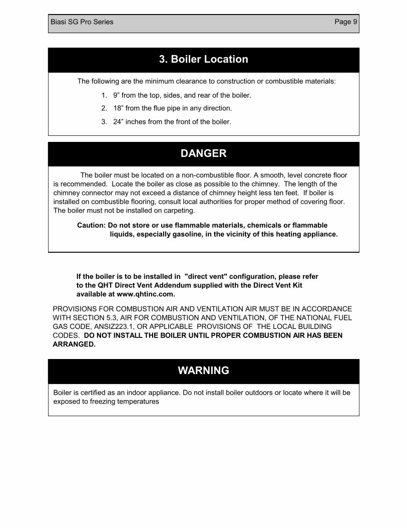
3. Boiler Location
The following are the minimum clearance to construction or combustible materials:
1. 9” from the top, sides, and rear of the boiler.
2. 18” from the flue pipe in any direction.
3. 24” inches from the front of the boiler.
DANGER
The boiler must be located on a non-combustible floor. A smooth, level concrete floor
is recommended. Locate the boiler as close as possible to the chimney. The length of the
chimney connector may not exceed a distance of chimney height less ten feet. If boiler is
installed on combustible flooring, consult local authorities for proper method of covering floor.
The boiler must not be installed on carpeting.
Caution: Do not store or use flammable materials, chemicals or flammable
liquids, especially gasoline, in the vicinity of this heating appliance.
WARNING
Boiler is certified as an indoor appliance. Do not install boiler outdoors or locate where it will be
exposed to freezing temperatures

Page 10 Biasi SG Pro Series
USE ONLY THE LISTED BOILER SYSTEM COMPONENTS AND
SPECIFIED OIL AND GAS BURNER COMPONENTS SUPPLIED WITH
THE BIASI SG PRO BOILER.
Please refer to figures below for Barometric Damper location (gas burners only) and to the
right for the proper location of the trim components.
Barometric Damper w/
Manual Reset Spill Switch
(Gas Burner Only)
BIASI SG
T-handle
Gas Cock
Alternative
Location
Drip Leg
Gas Train Positive Pressure
Gas Fired
4.1 Boiler Trim Components
Union
Trim Kit Components:
1 — Control panel with temperature and pressure gauges and Hydrolevel Touch Panel control
1 — Immersion well
1 — 30 PSI pressure relief valve
1 — ¾” Boiler drain
1 — 12”x12” Cera-fiber blanket
1 — Burner mounting hardware
1 — ¾” X 3” Nipple
1 — ¾” 90° Elbow
1 — Double Acting Barometric
Damper with Manual Reset Spill
Switch (Gas systems only)
Biasi SG Pro Series Page 11
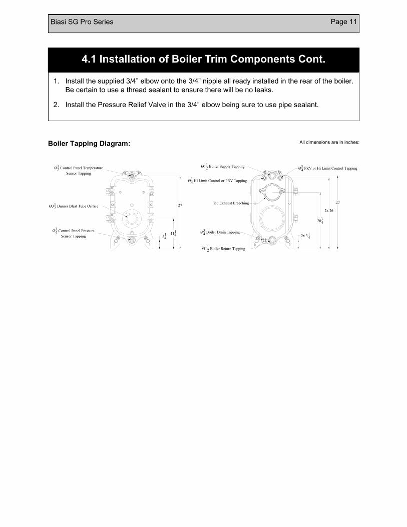
1. Install the supplied 3/4” elbow onto the 3/4” nipple all ready installed in the rear of the boiler.
Be certain to use a thread sealant to ensure there will be no leaks.
2. Install the Pressure Relief Valve in the 3/4” elbow being sure to use pipe sealant.
4.1 Installation of Boiler Trim Components Cont.
Boiler Tapping Diagram: All dimensions are in inches:
27
2034
2x 314
Ø112 Boiler Supply Tapping
Ø112 Boiler Return Tapping
Ø34 Boiler Drain Tapping
Ø34 Hi Limit Control or PRV Tapping
Ø34 PRV or Hi Limit Control Tapping
Ø6 Exhaust Breeching
2x 26
Ø34 Control Panel Pressure
Sensor Tapping
Ø12 Control Panel Temperature
Sensor Tapping
Ø312 Burner Blast Tube Orifice 27
111431
4

Page 12 Biasi SG Pro Series
4.2 Reversing the Boiler Door Hinge
1. Remove the boiler door by unscrewing the two nuts holding the door onto the boiler
2. Remove the hinge components from the door and boiler body.
3. Take the boiler hinge elements (it has the pins on the ends) and place them on the upper and lower studs of the side of the boiler that you want the door to swing towards. Install them such that the stud comes through the upper “U”-section and the pin on the boiler block is under the lower “U” section of the hinge. (see Figure 4.1 below) Tighten each with a washer and a nut.
4. Next place the door catch under the top post of the side opposite that on which the hinges are mounted. This is mounted in a similar manner to the hinges. Tighten with a washer and a nut.
5. Place the bolts with a washer on each through the back of the ears on the door in the upper and lower holes on the same side as the hinges are mounted on.
6. Place the upper hinge element onto the bolt and tighten with a washer and a nut.
7. Place the doors hinges onto the pins of the hinge on the boiler.
8. The installation of the hinge is complete. Now, close the door and put the nuts and washers back onto the door to keep shut
SG Hinge Kit Components:
5—Nuts
7—Washers
2—Bolts
2—Lower hinge elements
2—Upper hinge elements
1—Door Catch
Biasi SG Pro Series Page 13
SAFETY RELIEF VALVE
1. The safety relief valve should be piped into one of the two upper tapings in the rear of the boiler
2. The relief valve should be piped in with a doping compound using the supplied hardware in the trim kit
3. Pipe the discharge of the safety relief valve to prevent injury in the event of pressure relief. Pipe the discharge to a drain or to the floor if a drain is not available. Provide piping that is the same size as the safety relief valve outlet.
All piping must conform to state and local codes. Page 7 shows the location and size of the boiler tappings. Be sure to allow enough room to clear the casing by installing sufficient sized nipples. It is recommended to install unions and shutoff valves at the inlet and outlet of the boiler, so it may be easily isolated for service.
Install the provided pressure relief valve so the discharge is piped directly to a drain, if possible. If not, the discharge should be piped to the floor. In either case, the discharge pipe should be of the same diameter as the outlet of the relief valve, with no valves or obstructions to impede overflow from the boiler.
For Canadian installations, it is required to install a low water cut off if the boiler is installed above the level of radiation. Even if the boiler is installed below the level of radiation it is strongly recommended that a low water cut off be installed.
Install manual and/or automatic air venting devices at the high points in the system to eliminate trapped air. The weight of all piping should be supported by suitable hangars and floor stands, not by the boiler’s purging/expansion station. Clearance for hot water pipes are 1 inch to combustibles.
It is recommended that the make-up water line have a backflow preventer and a pressure-reducing valve to reduce line pressure to 10 to 15 psi installed adjacent to the boiler.
In the case of a gas installation, the boiler should be installed such that the gas ignition system components are protected from water (dripping, spraying, etc.) during appliance operation and service (circulator replacement, condensate trap, control replacement, etc.).
If the boiler is to be used in conjunction with a refrigeration system, it must be piped in parallel with refrigeration system with the appropriate valves to ensure the chilled medium does not enter the boiler. Also if the boiler is connected to heating coils in an air handling system, where the coil could be exposed to cold air circulation. The boiler must have flow control valves or other automatic means to prevent gravity circulation of the boiler water during the cooling cycle.
NOTE: If the heating system is to be filled with antifreeze, use only formulations expressly made for hydronic heating systems (such as propylene glycol). Do not use automotive types of antifreeze (ethylene glycol). Use of antifreeze will alter system output and characteristics. Consult a factory representative for details or assistance.
5. Piping the Boiler

Page 14 Biasi SG Pro Series
6. Intake Venting
1. Be certain adequate air is available for combustion and ventilation.
a.) Boiler located in unconfined space:
Installation in large areas, such as basements can usually be assumed to provide sufficient air. An unconfined space is defined as having an area of greater than 50 square feet for every 1000 Btuh of input.
b.) Boiler located in confined space:
If all air for combustion and ventilation is to come within the building: Two (2) openings shall be provided with one (1) opening commencing within 12 inches of the top and one (1) opening commencing within 12 inches of the bottom of the enclosure. These openings shall not be located closer than 3 inches from either the top or bottom of the enclosure and shall be open to areas connecting freely with the outdoors. The area of each opening shall not be less than one square inch per 1000 BTU/HR. of total input rating of all appliances within the enclosure; with a minimum of 100 square inches for each opening.
If all the air for combustion and ventilation is to come from outside the building; two (2) openings shall be provided with one opening commencing within 12 inches of the top and an opening commencing within 12 inches of the bottom of the enclosure. These openings shall not be located closer than 3 inches from either the top or bottom of the enclosure, and shall connect directly or by ducts with the outdoors. The area of each opening shall be equal to one square inch per 2000 BTU/HR of total input rating. If ducts are used to convey the air, vertical ducts require areas of one square inch per 4000 BTU/hr horizontal ducts require one square inch per 2000 BTU/hr. Ducts shall have the same cross sectional area as the full area of the openings to which they connect.
The upper opening is essential for maintenance of proper circulation of air with the boiler and reasonable ambient temperature in order to maintain proper control temperatures. When a duct is used for ventilation, check for louver free net area and correct for screen resistance to ensure that the ventilation area has been satisfied. DO NOT INSTALL THE BOILER UNTIL PROPER COMBUSTION AIR HAS BEEN ARRANGED.
c.) Boiler located in a room under negative pressure:
If the boiler is to be installed within a home where the operation of exhaust fans, attic fans, kitchen ventilation systems, clothes dryers or fireplaces may create severe negative vent pressures causing unsatisfactory combustion and venting, special provisions should be made for additional make-up air to supply the other air requirements. If building is of tight construction, combustion air requirements may not be met and combustion air ducts from outside may be necessary. Please refer to NFPA No. 31.
Biasi SG Pro Series Page 15
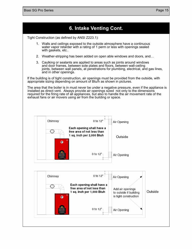
Tight Construction (as defined by ANSI Z223.1):
1. Walls and ceilings exposed to the outside atmosphere have a continuous water vapor retarder with a rating of 1 perm or less with openings sealed with gaskets, etc..
2. Weather-stripping has been added on open able windows and doors, and…
3. Caulking or sealants are applied to areas such as joints around windows and door frames, between sole plates and floors, between wall-ceiling joints, between wall panels, at penetrations for plumbing, electrical, and gas lines, and in other openings.
If the building is of tight construction, air openings must be provided from the outside, with appropriate sizing depending on amount of Btu/h as shown in pictures.
The area that the boiler is in must never be under a negative pressure, even if the appliance is installed as direct vent. Always provide air openings sized not only to the dimensions required for the firing rate of all appliances, but also to handle the air movement rate of the exhaust fans or air movers using air from the building or space.
6. Intake Venting Cont.
Page 16 Biasi SG Pro Series
The SG boiler is a high efficiency unit that requires proper venting. The boiler must be vented to the outdoors by means of a tile lined masonry or an approved pre-fabricated chimney of the size and height recommended by the vent manufacturer or by a listed "power venting" unit which provides draft by mechanical venting. In many installations, particularly older interior and most exterior chimneys, a corrosion resistant liner should be installed. Please consult liner manufacturer for the appropriate chimney liner.
The chimney discharge opening must be located at least 24 inches above any part of the building structure within 4 feet of the chimney. Be sure the chimney and smoke pipe don't become obstructed by squirrels, bird nests, soot buildup, chimney liner deterioration, etc.. If using a "power venter" system, it is suggested that it should be installed on the leeward side of the house. (Please consult with manufacturer of "power venter" for requirements concerning clearances from combustibles and distances from doors and windows.) The "venter" must be installed by a licensed burner mechanic and done in accordance with local codes. This is a very low stack temperature boiler (350F gross temp.) so caution should be used when connecting to an outside built chimney. Should you have concern that the flue gases could condense, then you should consider lining the chimney or using a listed, "power venting" or " direct venting unit". If "power venting" is used to discharge flue gases, then the power vent unit should be equipped with a postpurge control such as a delay-off, timing control to prevent problems with fogging and nozzle post drip.
The determining connection from the boiler to the chimney should be as short as possible, with a minimum number of elbows. The equivalent length of the chimney connector may not exceed a distance of chimney height less ten feet. The The vent pipe must have a vertical rise of at least 1/4 inch per foot of horizontal run. The vent pipe must be of the same diameter as the flue outlet on the boiler. The chimney connector should have a minimum thickness of 24 gauge, be corrosion resistant (galvanized) steel, assembled with a minimum of three (3) sheet-metal screws in each joint. In some houses, a barometric draft control isn't required as the SG is designed to be pressure-fired, however in high draft situations which exceed the flue gas resistance through the boiler, a barometric draft control is recommended. The over fire draft should be between 0 and .06 inches of water column. The draft at the breech should be enough to overcome the over fire draft at all times.
7. Exhaust Venting
Common vent exhaust:
If this boiler is replacing one that was part of a common venting system, it is likely that the vent is to large to vent the appliances still attached to it. To prevent this, at the time of removal, the following steps shall be followed with each appliance remaining connected to the common venting system. Place each unit in operation, while the other appliances remaining connected to the common venting system are not in operation.
1. Seal any unused openings in the common venting system.
2. Visually inspect the venting system for proper size and horizontal pitch and determine there is no blockage or restriction, leakage, corrosion and other deficiencies which could cause an unsafe condition.
7.1 Common Exhaust Venting

Biasi SG Pro Series Page 17
3. Insofar as practical, close all building doors and windows and all doors between the space in which the appliance remaining connected to the common venting system are located and other spaces of the building . Turn on any appliance not connected to the common vent system. Turn on all exhaust fans except for summer exhaust fans. Close the fireplace damper if applicable.
4. Place in operation the appliance being inspected. Follow the lighting instructions. Adjust thermostat so appliance will operate continuously.
5. Test for spillage at the barometric damper after 5 minutes of main burner operation. Use the flame of a match or candle, or smoke from a cigarette, cigar or pipe.
6. After it has been determined that each appliance remaining connected to the common venting system property vents when tested as outlined above, return doors, windows, exhaust fans, fireplace dampers and any other gas-burning appliance to their previous condition of use.
7. Any improper operation of the common venting system should be corrected so the installation conforms with the National fuel Gas Code, ANSI Z223.1 and/or CAN/CGA B149, Installation Codes. When resizing any portion of the common venting system, the common venting system should be resized to approach the minimum size as determined using the appropriate tables in Part 11 of the National Fuel Gas Code, ANSI Z223.1, and/or CAN/CGA B149, Installation Codes.
7.1 Common Exhaust Venting Cont.
1. Pierce a 5/8” hole into the vent pipe near the appliance outlet. Remove one of the securing nuts from the pipe of the safety switch. Tighten the other securing nut onto the pipe as far as possible.
2. Insert the threaded pipe end into the pierced hole, then install the securing nut, then install the securing nut, which was removed in step 1, and tighten securely.
3. Please consult the wiring section of this manual for the wiring of the blocked flue switch.
7.2 Blocked Flue Switch: (Canada Only)

Page 18 Biasi SG Pro Series
Good, reliable operation with a minimum of service, starts with attention to the small details:
1. Setting the nozzle position and electrodes "by the book" using the
manufacturer's gauges.
2. Installing a quality micron filter at the burner.
3. Making careful/tight flare connections without couplings on oil suction line.
4. Checking fuel pump pressure.
5. Checking draft at the breeching to insure it is adequate to overcome flue
gas resistance.
6. Setting the air band properly with well maintained instruments. A good
target is 11% to 12.75% of (CO2) or 6.0% to 3.5% of (O2).
7. Checking for a zero smoke level in the flue pipe.
To ensure proper burner setup, gauges should be used to check things such as the pump pressure, CO2 levels, etc...
8. Oil Burner Setup
For boilers connected to gas vents or chimneys, vent installations shall be in accordance with part 7, Venting of Equipment, of the National Fuel Gas Code, ANSI Z223.1 or Section 7, Venting Systems and Air Supply for Appliances, of the CAN/CGA B149, Installation Codes, or applicable provisions of the local building codes.
Vent connectors serving appliances vented by natural draft shall not be connected into any portion of mechanical draft systems operating under positive pressure.
7.2 Gas Venting

Biasi SG Pro Series Page 19
This page is only for boilers using an oil burner. If a gas burner is being used, please refer to
page 13 for the proper setup of the burner and gas lines.
8.1 Oil Burner Setup
Beckett
NX
Boiler Model SG-3 SG-4
Burner Model NEC 1202 NEC 1202
Firing Rate 0.91 1.22
Insertion Depth 6" 6"
Nozzle .75 X 60B 1.00 X 60B
Spray Pattern B B
Pump Pressure 145 psi 145 psi
Head Type 9-slot 9-slot
Head Position 2.5 4.5
Carlin
Boiler Model SG-3 SG-4 SG-5
Burner Model EZ-1 EZ-1 EZ-1
Firing Rate 0.91 1.22 1.52
Insertion Depth 3.5" 3.5" 3.5"
Nozzle .65 x60 1.00 x 60 1.25 X 60
Spray Pattern B B B
Pump Pressure 175 psi 135 psi 140 psi
Head` .60/.65 .85/1.00 1.10/1.25
Air Gate 0.9 1.2 1.65
BURNER MANUFACTURER Riello
R-40 Series
Boiler Model SG-3 SG-4 SG-5
Burner Model F-5 F-5 F-5
Firing Rate 0.91 1.22 1.52
Insertion Depth 5" 5" 5"
Nozzle .75 X 60 1.00 x 60 1.25 X 60
Spray Pattern W W W
Pump Pressure 145 psi 145 psi 145 psi
Turbulator 1 3 4
Air Gate 2.5 3 4
BURNER MANUFACTURER
BURNER MANUFACTURER
For Carlin and Beckett burners to qualify for Energy Star, it is necessary to install and automated vent damper to prevent off cycle losses.

Page 20 Biasi SG Pro Series
Good, reliable operation with a minimum of service, starts with attention to the small details:
1. Setting electrodes "by the book" using the manufacturer's gauges.
2. Checking gas pressure to the burner and out of the gas valve.
3. Checking draft at the breeching to insure it is adequate to overcome flue
gas resistance.
4. Setting the air band properly with well maintained instruments. A good
target is 8.5% to 9.5% of (CO2) for Natural Gas or 10% to 11% of (CO2) for Propane.
7. Verify a CO level is less than 200 ppm
This page is only for boilers using a gas burner. If an oil burner is being used, please refer to
page 12 for the proper setup of the burner.
To determine how much gas is coming into the burner,
or to set the gas meter correctly, the following formula
can be used.
The chart to the right can be used to determine the
flow rate depending upon the time per revolution and
the size of the gas meter dial.
Ft3/hr = [3600/(sec. Per rev.)/*(Size of gas meter)
Size of Gas Meter Dial
(Cubic Foot) Seconds per
Revolution 0.5 1 2
20 90 180 360
25 72 144 288
30 60 120 240
35 51 103 206
40 45 90 180
45 40 80 160
50 36 72 144
55 33 65 131
60 30 60 120
8.2 Gas Burner Setup
Riello Natural Gas Propane
Boiler
Model Burner Model
Input
(MBH)
Man. Pres.
(W.C.)
Head
Setting
Air
Gate
Orifice
Man. Pres.
(W.C.)
Head
Setting
Air
Gate Orifice
SG-3 R200 140 3.5” 2.0 2.25 B5 3.5” 2.0 2.25 B15
SG-4 R200 182 3.5” 3.0 2.75 B6 3.5” 3.0 2.5 B16
SG-5 R400 224 3.5” 1.0 2.0 C3 3.5” 1.0 1.5 C13
Biasi SG Pro Series Page 21
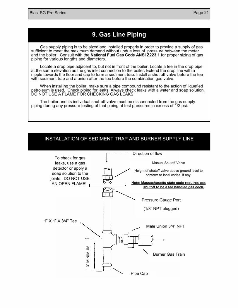
Gas supply piping is to be sized and installed properly in order to provide a supply of gas sufficient to meet the maximum demand without undue loss of pressure between the meter and the boiler. Consult with the National Fuel Gas Code ANSI Z223.1 for proper sizing of gas piping for various lengths and diameters.
Locate a drop pipe adjacent to, but not in front of the boiler. Locate a tee in the drop pipe at the same elevation as the gas inlet connection to the boiler. Extend the drop line with a nipple towards the floor and cap to form a sediment trap. Install a shut off valve before the tee with sediment trap and a union after the tee before the combination gas valve.
When installing the boiler, make sure a pipe compound resistant to the action of liquefied petroleum is used. Check piping for leaks. Always check leaks with a water and soap solution. DO NOT USE A FLAME FOR CHECKING GAS LEAKS
The boiler and its individual shut-off valve must be disconnected from the gas supply piping during any pressure testing of that piping at test pressures in excess of 1/2 psi.
To check for gas
leaks, use a gas
detector or apply a
soap solution to the
joints. DO NOT USE
AN OPEN FLAME!
Direction of flow
Pressure Gauge Port
(1/8” NPT plugged)
1” X 1” X 3/4” Tee
Male Union 3/4” NPT
Burner Gas Train
Pipe Cap
3”
MIN
IMU
M
9. Gas Line Piping
INSTALLATION OF SEDIMENT TRAP AND BURNER SUPPLY LINE
Manual Shutoff Valve
Height of shutoff valve above ground level to
conform to local codes, if any.
Note: Massachusetts state code requires gas
shutoff to be a tee handled gas cock.
Page 22 Biasi SG Pro Series
Upon power up, the LCD display shows INITIALIZING, then immediately tests the low
water function displaying LOW WATER and flashing. The control then goes into normal
operating mode displaying the current status of the boiler.
Setting the HIGH LIMIT
The high limit is factory set at 190°F. To adjust, press the SET UP button. The screen
will display ADJUST SETTINGS. Then press the HI TEMP ▲ or ▼ buttons to select the
desired high limit. (Setting range: 100°-220°F)
Setting the LOW LIMIT
The low limit is designed to maintain temperature in boilers equipped with tankless coils
used for domestic hot water. The low limit is factory set to OFF and should be left that way for
the SG boiler. If it is necessary to set a low limit temperature, press the SET UP button. The
screen will display ADJUST SETTINGS. Press the LO TEMP ▲ or ▼ buttons to select the
desired low limit setting. (Setting range: OFF or 110°-200°F). For proper operation, the low
temperature limit setting should be at least 10° below the high limit setting.
NOTE: For cold start operation, the low limit must be turned OFF.
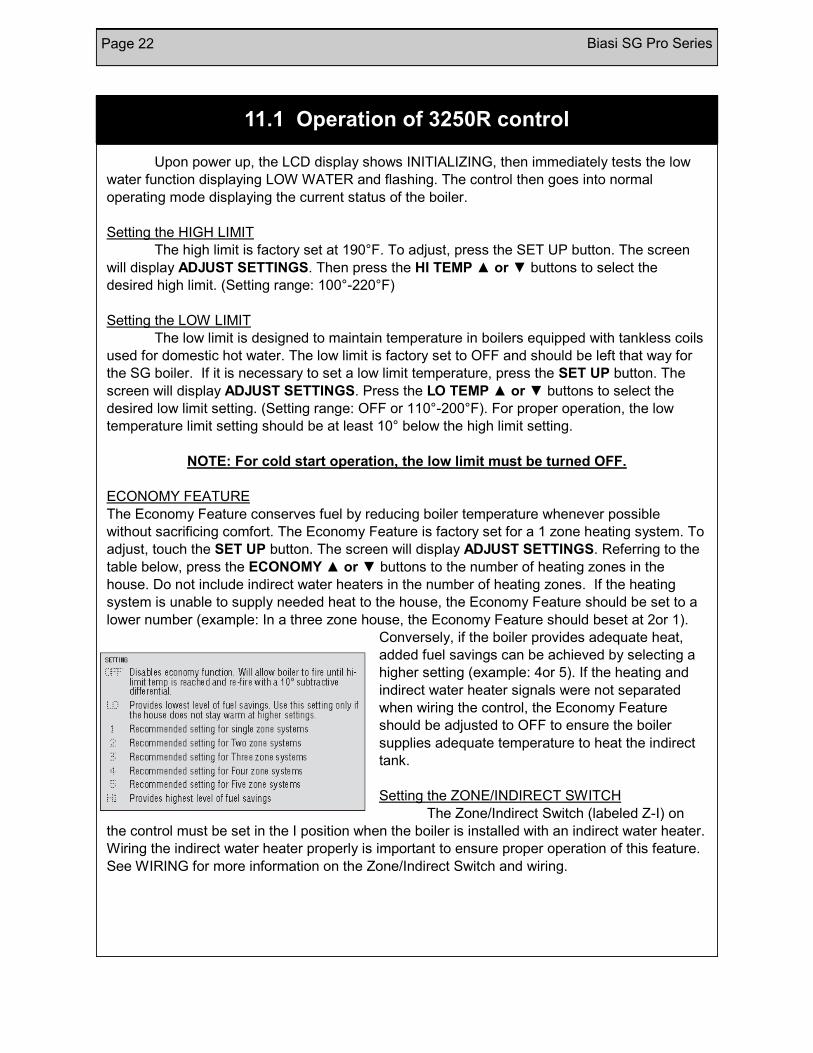
ECONOMY FEATURE
The Economy Feature conserves fuel by reducing boiler temperature whenever possible
without sacrificing comfort. The Economy Feature is factory set for a 1 zone heating system. To
adjust, touch the SET UP button. The screen will display ADJUST SETTINGS. Referring to the
table below, press the ECONOMY ▲ or ▼ buttons to the number of heating zones in the
house. Do not include indirect water heaters in the number of heating zones. If the heating
system is unable to supply needed heat to the house, the Economy Feature should be set to a
lower number (example: In a three zone house, the Economy Feature should beset at 2or 1).
Conversely, if the boiler provides adequate heat,
added fuel savings can be achieved by selecting a
higher setting (example: 4or 5). If the heating and
indirect water heater signals were not separated
when wiring the control, the Economy Feature
should be adjusted to OFF to ensure the boiler
supplies adequate temperature to heat the indirect
tank.
Setting the ZONE/INDIRECT SWITCH
The Zone/Indirect Switch (labeled Z-I) on
the control must be set in the I position when the boiler is installed with an indirect water heater.
Wiring the indirect water heater properly is important to ensure proper operation of this feature.
See WIRING for more information on the Zone/Indirect Switch and wiring.
11.1 Operation of 3250R control
Biasi SG Pro Series Page 23
The electricity to the boiler shall come from a dedicated breaker in the electric
service box. A service switch should be mounted on the side of the boiler so the burner
technician can service the burner and controls. The electrical wiring should be routed so as not
to interfere with normal servicing of the boiler. Wiring done in the field between devices not
attached to boiler shall conform with the temperature limitations for type T wire (63F/35C) or
other specified wire as applicable when installed in accordance to manufacturer's
instructions and wiring diagrams.
If an external electrical source is utilized, the boiler, when installed, must be electrically
bonded to ground in accordance with the requirements of the authority having jurisdiction or, in
the absence of such requirements, with the National Electrical Code, ANSI/NFPA 70 and/or the
Canadian Electrical Code Part 1, CSA C22.1, Electrical Code.
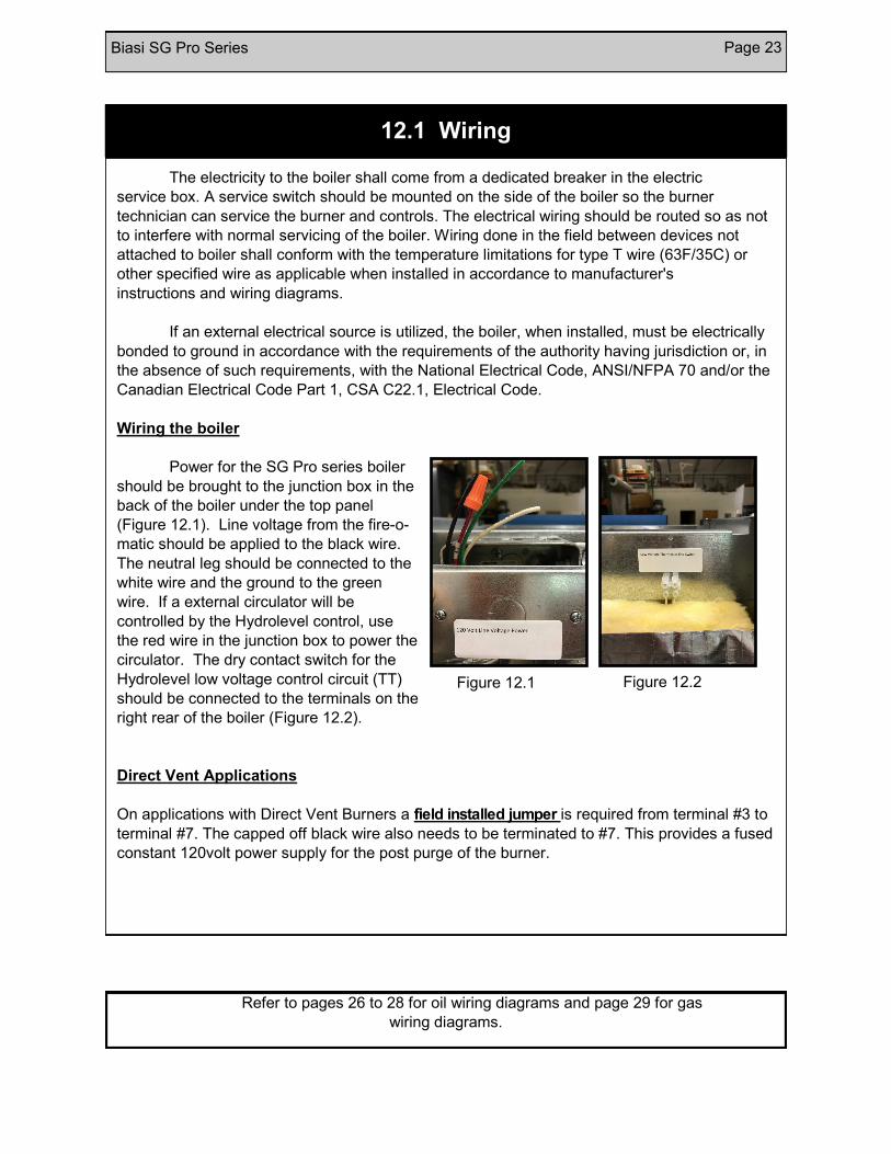
Wiring the boiler
Power for the SG Pro series boiler
should be brought to the junction box in the
back of the boiler under the top panel
(Figure 12.1). Line voltage from the fire-o-
matic should be applied to the black wire.
The neutral leg should be connected to the
white wire and the ground to the green
wire. If a external circulator will be
controlled by the Hydrolevel control, use
the red wire in the junction box to power the
circulator. The dry contact switch for the
Hydrolevel low voltage control circuit (TT)
should be connected to the terminals on the
right rear of the boiler (Figure 12.2).
Direct Vent Applications
On applications with Direct Vent Burners a field installed jumper is required from terminal #3 to
terminal #7. The capped off black wire also needs to be terminated to #7. This provides a fused
constant 120volt power supply for the post purge of the burner.
Refer to pages 26 to 28 for oil wiring diagrams and page 29 for gas
wiring diagrams.
12.1 Wiring
Figure 12.1 Figure 12.2
Page 24 Biasi SG Pro Series
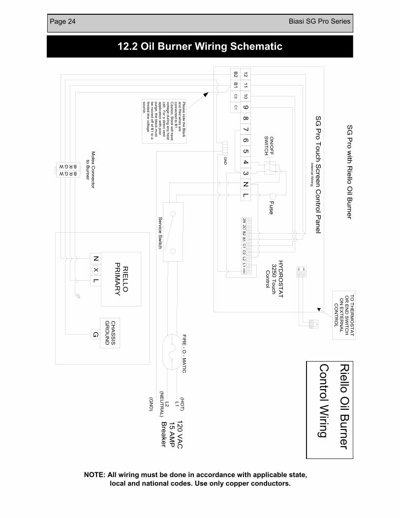
12.2 Oil Burner Wiring Schematic
NOTE: All wiring must be done in accordance with applicable state,
local and national codes. Use only copper conductors.
ON
/OF
F
SW
ITC
HMo
lex C
on
ne
cto
r
to B
urn
er
FIR
E - O
- MA
TIC
(HO
T)
L1
L2
(NE
UT
RA
L)
12
0 V
AC
15
AM
P
Bre
ake
rS
erv
ice
Sw
itch
TO
TH
ER
MO
ST
AT
OR
EN
D S
WIT
CH
ON
EX
TE
RN
AL
CO
NT
RO
L
HY
DR
OS
TA
T
32
50
To
uch
Co
ntro
l
T T
SG
Pro
To
uch
Scre
en
Co
ntro
l Pa
ne
lIn
tern
al W
iring
B R G W
B R G W
L1
L2
C1
C2
B1
B2
ZC
ZR
GN
D5
LN
34
10
98
76
11
12
RIE
LL
O
PR
IMA
RY
NL
X
CH
AS
SIS
GR
OU
ND
G
SG
Pro
with
Rie
llo O
il Bu
rne
r
Fu
se
GN
D
(GN
D)
C2
C1
B1
B2
Ple
ase
no
te th
e B
lack
an
d R
ed
wire
s a
re
co
nn
ecte
d to
B1
.
Ca
utio
n, B
lack w
ill ha
ve
vo
ltag
e d
urin
g a
ny h
ea
t
ca
ll. Fo
r a d
irect v
en
t
ap
plic
atio
n w
ith p
ost
pu
rge
, the
bla
ck m
ust
be
mo
ve
d o
ff of B
1 to
a
limite
d lin
e v
olta
ge
so
urc
e.
Rie
llo O
il Burn
er
Con
trol W
iring
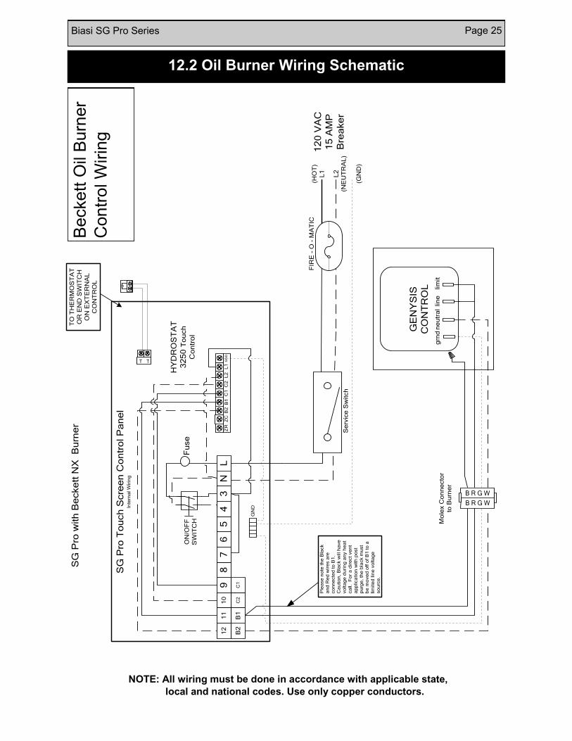
Biasi SG Pro Series Page 25
12.2 Oil Burner Wiring Schematic
NOTE: All wiring must be done in accordance with applicable state,
local and national codes. Use only copper conductors.
ON
/OF
F
SW
ITC
H Mo
lex C
on
ne
cto
r
to B
urn
er
FIR
E -
O -
MA
TIC
(HO
T)
L1
L2
(NE
UT
RA
L)
12
0 V
AC
15
AM
P
Bre
ake
rS
erv
ice
Sw
itch
TO
TH
ER
MO
ST
AT
OR
EN
D S
WIT
CH
ON
EX
TE
RN
AL
CO
NT
RO
L
HY
DR
OS
TA
T
32
50
To
uch
Co
ntr
ol
TT
SG
Pro
To
uch
Scre
en
Co
ntr
ol P
an
el
Inte
rna
l W
irin
g
B R G W
B R G W
L1
L2
C1
C2
B1
B2
ZC
ZR
GN
D5
LN
34
10
98
76
11
12
SG
Pro
with
Be
cke
tt N
X B
urn
er
Fu
se
GN
D
(GN
D)
C2
C1
B1
B2
GE
NY
SIS
CO
NT
RO
L lim
itlin
en
eu
tra
lg
rnd
Ple
ase
no
te t
he
Bla
ck
an
d R
ed
wir
es a
re
co
nn
ecte
d t
o B
1.
Ca
utio
n,
Bla
ck w
ill h
ave
vo
lta
ge
du
rin
g a
ny h
ea
t
ca
ll.
Fo
r a
dir
ect
ve
nt
ap
plica
tio
n w
ith
po
st
pu
rge
, th
e b
lack m
ust
be
mo
ve
d o
ff o
f B
1 t
o a
lim
ite
d lin
e v
olta
ge
so
urc
e.
Beckett
Oil
Burn
er
Contr
ol W
irin
g

Page 26 Biasi SG Pro Series
12.2 Oil Burner Wiring
ON
/OF
F
SW
ITC
HMo
lex C
on
ne
cto
r
to B
urn
er
FIR
E - O
- MA
TIC
(HO
T)
L1
L2
(NE
UT
RA
L)
12
0 V
AC
15
AM
P
Bre
ake
rS
erv
ice
Sw
itch
TO
TH
ER
MO
ST
AT
OR
EN
D S
WIT
CH
ON
EX
TE
RN
AL
CO
NT
RO
L
HY
DR
OS
TA
T
32
50
To
uch
Co
ntro
l
T T
SG
Pro
To
uch
Scre
en
Co
ntro
l Pa
ne
lIn
tern
al W
iring
B R G W
B R G W
L1
L2
C1
C2
B1
B2
ZC
ZR
GN
D5
LN
34
10
98
76
11
12
SG
Pro
with
Ca
rlin B
urn
er
Fu
se
GN
D
(GN
D)
C2
C1
B1
B2
limit
line
ne
utra
lg
rnd Ca
rlin 7
02
00
Ple
ase
no
te th
e B
lack
an
d R
ed
wire
s a
re
co
nn
ecte
d to
B1
.
Ca
utio
n, B
lack w
ill ha
ve
vo
ltag
e d
urin
g a
ny h
ea
t
ca
ll. Fo
r a d
irect v
en
t
ap
plic
atio
n w
ith p
ost
pu
rge
, the
bla
ck m
ust
be
mo
ve
d o
ff of B
1 to
a
limite
d lin
e v
olta
ge
so
urc
e.
NOTE: All wiring must be done in accordance with applicable state,
local and national codes. Use only copper conductors.
Carlin
Oil B
urn
er
Con
trol W
iring
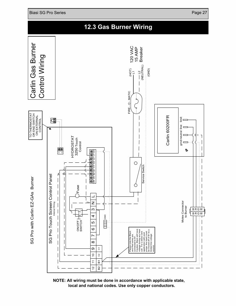
Biasi SG Pro Series Page 27
12.3 Gas Burner Wiring
NOTE: All wiring must be done in accordance with applicable state,
local and national codes. Use only copper conductors.
ON
/OF
F
SW
ITC
H Mo
lex C
on
ne
cto
r
to B
urn
er
FIR
E -
O -
MA
TIC
(HO
T)
L1
L2
(NE
UT
RA
L)
12
0 V
AC
15
AM
P
Bre
ake
rS
erv
ice
Sw
itch
TO
TH
ER
MO
ST
AT
OR
EN
D S
WIT
CH
ON
EX
TE
RN
AL
CO
NT
RO
L
HY
DR
OS
TA
T
32
50
To
uch
Co
ntr
ol
TT
SG
Pro
To
uch
Scre
en
Co
ntr
ol P
an
el
Inte
rna
l W
irin
g
B R G W
B R G W
L1
L2
C1
C2
B1
B2
ZC
ZR
GN
D5
LN
34
10
98
76
11
12
SG
Pro
with
Ca
rlin
EZ
-GA
s B
urn
er
Fu
se
GN
D
(GN
D)
C2
C1
B1
B2
lim
itlin
en
eu
tra
lg
rnd
Ca
rlin
60
20
0F
R
Ple
ase
no
te t
he
Bla
ck
an
d R
ed
wir
es a
re
co
nn
ecte
d t
o B
1.
Ca
utio
n,
Bla
ck w
ill h
ave
vo
lta
ge
du
rin
g a
ny h
ea
t
ca
ll.
Fo
r a
dir
ect
ve
nt
ap
plica
tio
n w
ith
po
st
pu
rge
, th
e b
lack m
ust
be
mo
ve
d o
ff o
f B
1 t
o a
lim
ite
d lin
e v
olta
ge
so
urc
e.
Carlin
Gas B
urn
er
Contr
ol W
irin
g
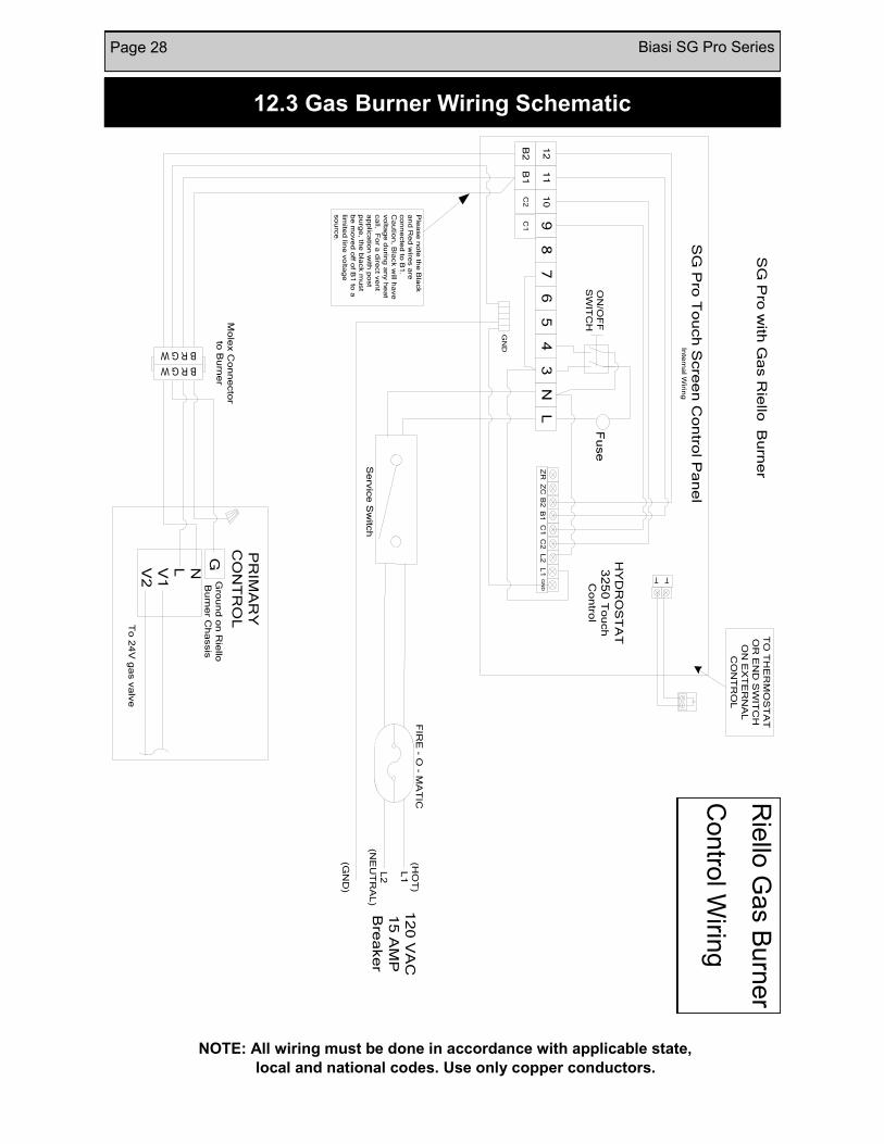
Page 28 Biasi SG Pro Series
12.3 Gas Burner Wiring Schematic
NOTE: All wiring must be done in accordance with applicable state,
local and national codes. Use only copper conductors.
Rie
llo G
as B
urn
er
Con
trol W
iring
ON
/OF
F
SW
ITC
HMo
lex C
on
ne
cto
r
to B
urn
er
FIR
E - O
- MA
TIC
(HO
T)
L1
L2
(NE
UT
RA
L)
12
0 V
AC
15
AM
P
Bre
ake
rS
erv
ice
Sw
itch
TO
TH
ER
MO
ST
AT
OR
EN
D S
WIT
CH
ON
EX
TE
RN
AL
CO
NT
RO
L
HY
DR
OS
TA
T
32
50
To
uch
Co
ntro
l
T T
SG
Pro
To
uch
Scre
en
Co
ntro
l Pa
ne
lIn
tern
al W
iring
B R G W
B R G W
L1
L2
C1
C2
B1
B2
ZC
ZR
GN
D5
LN
34
10
98
76
11
12
SG
Pro
with
Ga
s R
iello
Bu
rne
r
Fu
se
GN
D
(GN
D)
C2
C1
B1
B2
NLV1
V2
PR
IMA
RY
CO
NT
RO
L
To
24
V g
as v
alv
e
GG
rou
nd
on
Rie
llo
Bu
rne
r Ch
assis
Ple
ase
no
te th
e B
lack
an
d R
ed
wire
s a
re
co
nn
ecte
d to
B1
.
Ca
utio
n, B
lack w
ill ha
ve
vo
ltag
e d
urin
g a
ny h
ea
t
ca
ll. Fo
r a d
irect v
en
t
ap
plic
atio
n w
ith p
ost
pu
rge
, the
bla
ck m
ust
be
mo
ve
d o
ff of B
1 to
a
limite
d lin
e v
olta
ge
so
urc
e.
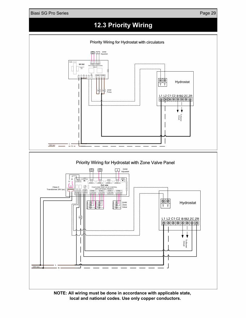
Biasi SG Pro Series Page 29
12.3 Priority Wiring
NOTE: All wiring must be done in accordance with applicable state,
local and national codes. Use only copper conductors.
ZCB1C1 B2C2L2L1
T TT T
ZR
Hydrostat
Priority Wiring for Hydrostat with circulators
To
Bu
rne
r
Circ
uit
120V (ac)N
L
N P ZC H X1 ZRX2
FUSE 1
AMP
24 VAC
POWER
TWO ZONE SWITCHING
RELAY
SR 502 ZONE1 ZONE2
ZONE1 ZONE2
T ADHW
Aquastat
DHW
Pump
FOUR ZONE ZONE VALVE CONTROL
WITH OPTIONAL PRIORITY
OFF
ON
ZONE 4
PRIORITY
MOD
E RESE
T
ZVC 404
1 2 3 4ZONE 1
1 2 3 4ZONE 2
1 2 3 4ZONE 3
1 2 3 4ZONE 4
ZONE 4
RELAY
N/
O
N/
CCOMEXTRA
END
SWITCH
MAIN
END
SWITCH
ZONE 1T T
ZONE 2T T
ZONE 3T T
ZONE 4T T
NORMA
L
FUSE
(3 AMP
MAX)
POWER IN
DHW
Aquastat
DHW
Zone
Valve
T T A
1
2
3
4
Mo
to r
En
dS
w
1
2
3
4
Mo
to r
En
dS
w
1
2
3
4
Mo
to r
En
dS
w
ZCB1C1 B2C2L2L1
T TT T
ZR
Hydrostat
Priority Wiring for Hydrostat with Zone Valve Panel
To
Bu
rne
r
Circ
uit
120V (ac)N
L
Class II
Transformer 24V (ac)
C
R
Page 30 Biasi SG Pro Series
Before a gas boiler may be commissioned, it’s gas connection must be leak tested before the
boiler may be put into operation and tested. After installation of oil/gas-fired boiler, operation and
performance tests shall be conducted to make certain that the burner is operating in an
acceptable manner and that all safety controls and devices function properly. It is critical that the
high limit, low water cutoff and burner "cad cell" relay be checked for normal operation before
leaving the job.
13. Commissioning
The Biasi boiler system should be serviced once a year.
1. Inspect the boiler and make sure it is operating normally, I.e. temperature and pressure.
2. Inspect the Pressure Relief Valve and manually set it off three times to ensure it is operating
normally and not leaking.
3. If a Low Water Cut-Off is installed follow the manufactures suggested maintenance and test
procedures.
4. Adjust room thermostat so there is a call for heat and test boiler high limit for proper
operation.
5. Turn boiler safety switch off.
6. Open swing door.
7. Brush upper passages first and then clean combustion camber of any debris with brush and
vacuum.
8. Remove smoke pipe and clean out debris from cleaning or soot build up.
9. Inspect smoke pipe for any corrosion before reinstalling. Replace if necessary.
10. Consult the burner manufacturers manual for annual maintenance of the burner.
14. Maintenance
Label all wires prior to disconnection when servicing controls. Wiring errors can cause
improper and dangerous operation.
CAUTION
Verify proper operation after servicing.
Notice

Biasi SG Pro Series Page 31
System Checkout:
Boiler Model No._________________ Serial No.__________
Original Purchaser: Installer:
_________________________ ______________________
_________________________ ______________________
_________________________ ______________________
Burner Manufacturer----------- Type of Oil Burner-------------
Burner Model No.-------------- Burner Serial No.--------------
Nozzle Manufacturer------------- Nozzle Spray Angle------------
G.P.H. -------------------- Type -----------------------
Burner Performance Tests:
GROSS STACK TEMPERATURE --------------------
ROOM TEMPERATURE (AMBIENT) -------------------
NET STACK TEMPERATURE ---------------------
CO2 -----------------
O2----------------
SMOKE READING ----------------
COMBUSTION EFFICIENCY----------------------
COMMENTS
15. Installer Notes
Page 32 Biasi SG Pro Series
16. Homeowner Information
1) STOP! Read the safety information on the side of the boiler. DO NOT START THE
BOILER UNLESS ALL CLEANOUT DOORS ARE SECURED AND SEALED.
(Skip to step 9 for oil burning boilers)
2) Set thermostat to lowest setting
3) Turn off all electric power to the appliance
4) Do not attempt to light the burner by hand
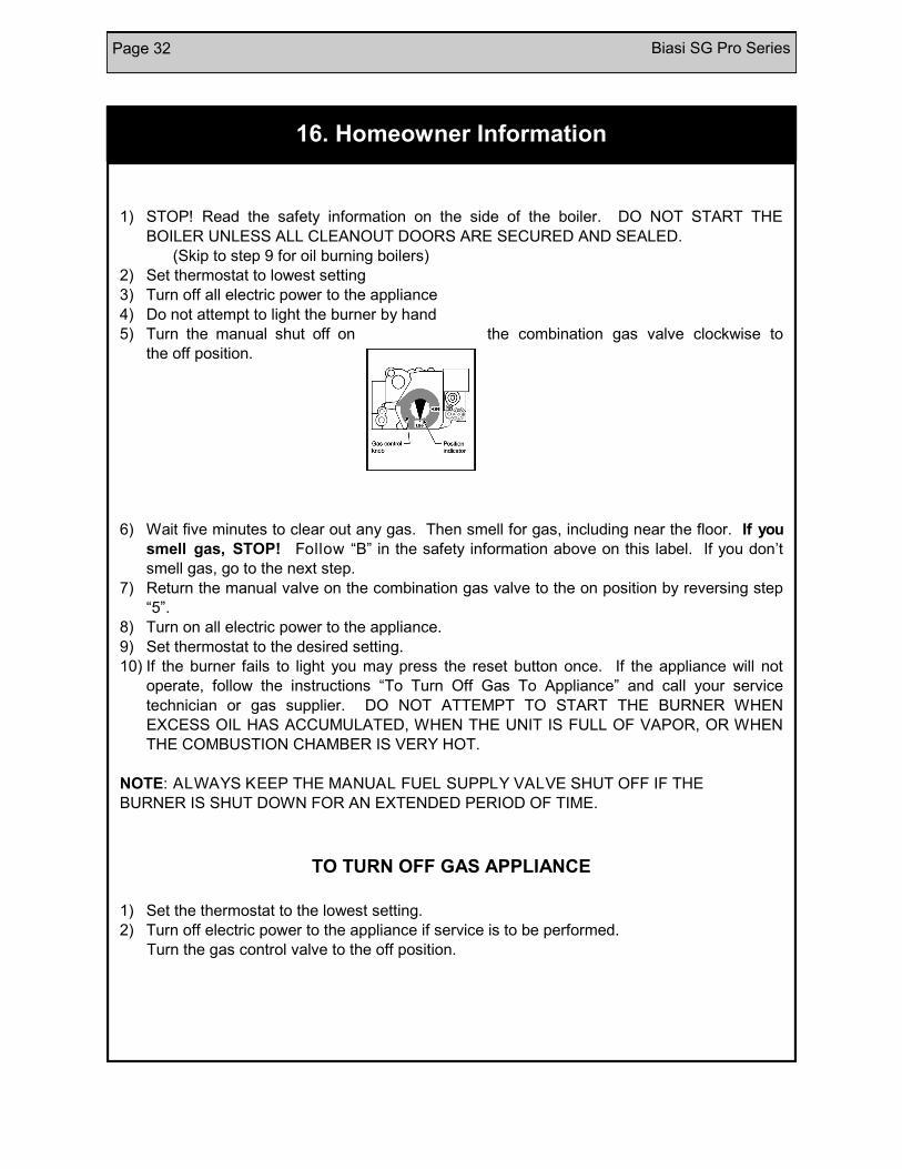
5) Turn the manual shut off on the combination gas valve clockwise to
the off position.
6) Wait five minutes to clear out any gas. Then smell for gas, including near the floor. If you
smell gas, STOP! Follow “B” in the safety information above on this label. If you don’t
smell gas, go to the next step.
7) Return the manual valve on the combination gas valve to the on position by reversing step
“5”.
8) Turn on all electric power to the appliance.
9) Set thermostat to the desired setting.
10) If the burner fails to light you may press the reset button once. If the appliance will not
operate, follow the instructions “To Turn Off Gas To Appliance” and call your service
technician or gas supplier. DO NOT ATTEMPT TO START THE BURNER WHEN
EXCESS OIL HAS ACCUMULATED, WHEN THE UNIT IS FULL OF VAPOR, OR WHEN
THE COMBUSTION CHAMBER IS VERY HOT.
NOTE: ALWAYS KEEP THE MANUAL FUEL SUPPLY VALVE SHUT OFF IF THE
BURNER IS SHUT DOWN FOR AN EXTENDED PERIOD OF TIME.
TO TURN OFF GAS APPLIANCE
1) Set the thermostat to the lowest setting.
2) Turn off electric power to the appliance if service is to be performed.
Turn the gas control valve to the off position.

Biasi SG Pro Series Page 33
Notes

Page 34 Biasi SG Pro Series
Notes

Biasi SG Pro Series Page 35
Notes

Page 36 Biasi SG Pro Series
Item#: SG/C-REV 011117
Manufactured by:
BIASI S.p.A.
Verona, Italy
Warranty
For BIASI SG Pro Series Residential
Cast-Iron Water Boilers FIRST YEAR-WARRANTY FOR SG SERIES RESIDENTIAL HOT WATER BOILERS:
QHT warrants that its cast-iron boiler and casing are free from defects in material and workmanship for one year from the date of
installation. If the boiler is found to be defective within this period, QHT will replace the boiler block or casing.
LIFETIME WARRANTY-WARRANTY FOR THE CAST IRON BOILER BLOCKS OF THE SG SERIES RESIDENTIAL BOILERS:
Biasi warrants that the cast-iron sections and nipples of the BIASI SG boilers are free from defects in material and workmanship for
the lifetime of the original single family home installation. If the SG boiler block is then found to be defective, QHT and Biasi will
replace the original cast iron boiler block.
These warranties are subject to the condition that a heating contractor whose principal occupation is the sale and installation of
heating equipment must have installed the boiler. PARTS, WHICH ARE COVERED, consists of all materials supplied by Biasi,
identified by QHT's part numbers in its literature. Other parts supplied in the casing, trim kit or in the burner pack carry their own
warranty and each manufacturer has responsibility for its own products.
NOTE: ANY PART, WHICH IS REPLACED UNDER WARRANTY, CARRIES ONLY THE UNEXPIRED PORTION OF THE
ORIGINAL WARRANTY.
OWNER RESPONSIBILITIES:
1. Provide for proper installation, which includes pressure relief and pressure reducing valves and high limit safety controls on
closed systems.
2. Provide qualified periodic service to prolong proper operation and service.
3. Insure that boiler is installed with approved burner and that installation conforms to all codes and ordinances.
4. This warranty does not apply to boilers, which are subject to misuse, abuse, neglect, alteration, accident, excessive
temperature, excessive pressure, or corrosive water or atmosphere.
5. Owner will be responsible for return of faulty components to Portsmouth, NH, freight pre-paid.
QHT and Biasi will not be responsible for:
1. Components that are part of the heating system, but were not manufactured by Biasi or QHT as part of the boiler.
2. The workmanship of the installers of SG boilers. Furthermore, this warranty does not assume any liability for unsatisfactory
performance caused by improper installation.
3. Any costs for labor to remove or replace the faulty component.
4. Improper burner application or adjustments, control settings, care or maintenance.
5. Any damage associated with corrosion or leakage due to the use of "non-barrier", plastic pipe in the heating system.
THIS WARRANTY DOES NOT EXTEND TO ANYONE EXCEPT THE FIRST PURCHASER AT RETAIL AND ONLY WHEN
THE BOILER IS IN THE ORIGINAL INSTALLATION SITE.
IMPLIED WARRANTIES OF FITNESS FOR A PARTICULAR PURPOSE AND MERCHANTABILITY SHALL BE LIMITED TO
THE DURATION OF THE EXPRESSED WARRANTY. BIASI AND QHT EXPRESSLY DISCLAIM AND EXCLUDE ANY
LIABILITY FOR CONSEQUENTIAL OR INCIDENTAL DAMAGES FOR BREACH OF ANY EXPRESSED OR IMPLIED
WARRANTY.
THIS WARRANTY GIVES YOU SPECIFIC LEGAL RIGHTS, AND YOU MAY HAVE OTHER RIGHTS THAT VARY FROM STATE
TO STATE.
For prompt warranty service, notify the installer, who, in turn, will notify the distributor from whom he purchased the boiler. If this
does not result in corrective action, contact Biasi through Quincy Hydronic Technology (Address Below) with details in support of
the warranty claim. All claims must be processed through proper trade channels. Contact with Biasi directly is not recommended
for rapid claim settlement.
Quincy Hydronic Technology,
3560 Lafayette Rd.
Portsmouth, NH, 03801
Tel. (603) 334-6400
www.qhtinc.com