bi war’’imii iuwoi’t
TRANSCRIPT

,,
i.
---7-1‘. NATIONAL ADVISORY COMMITTEE FOR AERONAUTI Si/---
.—--- bi
.
WAR’’IMII IUWOI’TORIGINALLY ISSUED
EITECTOF PROPI?13ER-AXIS ANGIE OF ATTACKOIVTERUST
DISTRIBUTIONOVER THE I!ROEELIERDISK R? REIATION
To WAKE—SURVEY~ OF TZRUSi’
By RobertE. Pendley
NACA. ‘ ‘;,“.,...,.. ..;-.,.,WASHINGTON
NACA WARTIME REPORTS are reprints of papers originally issued to provide rapid distribution ofadvance research results to an authorized group requiring them for the war effort. They were pre-viously held under a security status but are now unclassified. Some of these reports were not tech-nically edited. All have been reproduced without change in order to expedite general distr~bution.
,,.L - 517
,,, ,.. :, .- ..>-— .- - . ..-—-. ——
! 31176013639746 :
,
NACA ARR No● LsJ02b.1;fi
NATIONAL ADVISORY COMMITTEE FOR AERONA~GSr
&B. .. .- ”.. . . AWANGE RESTRLO?ZD REPORT.. .m. .......i:. . .1,.
EFFECT OF PROPELLER-AXIS ANGLE OF ATTACIQON THRUST ““
DISTRIBUTION OVER THE PROPEIJJ3R~SK IN RELATION
TO WAIQ3-SURVEYMEASUREMENT OF THRUST
By Robert E* Pendley
Tests were made .toinvestigate the variation ofthrust distribution over the propeller disk with angleof pitoh of the propeller thrust axis and to determinethe disposition and the minimum number of rakes neces-sary to measure the propeller thrustc The tests weremnde at a low Mach number f’ora low and 8 hir~ bladeangle with the pro~eller operating at three small anglesof pltoh, and.some of the tests were repea$ed at a higherMach number. The data obtained show that, for smallangles of pitch, large changes occur in the energy distri-bution in the wake which prohibit the use of a singlesurvey rake for thrust v.easure~entin flight tests andlimlt the use of a single rake in wind-tunnel tests.Under certain conditions, the energy distribution in thewake took on a sym?wtrical form and two diametricallyopposed survey rakes were shown to be satisfactory forobtaining propeller thrust.
INTRODUCTION
In many cases a total-pressure survey rake.is amore desirable means for measuring propeller thrust thma foroe system beoause not only the total thrust oan beobtained.from wake-survey data but ald~ the “actionof theelements along the propeller blade can be analyzed, Tnflight tests propeller thrust oan be measured only by owake surveys slnoe a satisfactory thrust meter has notyet been developed. Tn wind-tunnel investigations ofpropellers, however, the thrust obtained by use of a foroesystem often differs considerably from that obtained bysingle-rake wake-survey measurements.

2
., ...-
In refemnoe 1 t4e lack”o.ff@eement between thethrustobtained b~ wake surveys and by form tests wasexplainedas the result of huh drag. ad inorease In bodydrag due to the slipstream. In reference.2, publtshedlater, propeller-thrust-axis Inclination to the free-stream flow was shown to affect wake-survey measurementssl.noelarge variations in the distributeon of thrustover the propeller disk were found to oucur with varia-tlons in angle of pitch or yaw. Some of the lack ofagreement In the measurements of ref’erense1 might “therefore have been oaused by a small angle of’pftoh oryaw of the propeller thmst axis, although the hub &agand the inorease in body drag undoubtedly contributed t~the laok of agreement. T4e effect of propeller-thrust-axls inollnation to the free-stream flow on wake-surveymeasurements was further verified by tests made h the
~ley 8-foot high-spe~d tunnel. ln these tests, largedifferences In the thrust measured by a force system andby a single survey rake were found with the model at anangle of attack”of 1°, but exoellent agreement wasobtained when the tests were made at an angle ofattaok of OO.
- present tests were made tn the ~ley 8-foothl.gh-speedtunnel.to investigate the variation of thrustdistribution over th propeller disk with angle of pitohof the propeller thmst axis and”to determine the numberand radial position of.wake-survey rakes necessary toobtain the Tropeller thrust. Survey measurements witha alngle rake were made at six equally spaoed radialpositions around the propeller disk, The tests weremade at three small angles of attaok of the propellerthrust axis for a high and a low blade angle and attwo Mach znu?ibers.The effect of longitudinal positionof the rake was not investigated.
9YMBOLS
The symbols bed herein are defined aa followat
D propeller diamter, f~et
J advanoe-diameter ratio (V/nD)
M free-stream Maoh number ,.
n propeller rotational speeds revolutions per second
J

-1 NACA ARR ~Oa L’#02b
—
3
!.
rs.
R
v
w
x
X8
. .
ACT
dCT/dxs
CT~
aT
P
n
u
The
station radius, feeti.!..... ,,.... .--.,. . . ,....~.. ...7.-/.,, -,..ti.. .. -.wake-survey-station radius, feet
propeller tip radius, feet “ .
free-stream veloclty, feet per seeond
section relative air veloolty, feet per second
radial station (r/R)
radial station at survey plane (r*/R)
wake-survey thrust coefficient minus force-testthrust coefficient
thruot-coefficient gradient
wake-survey thrust coefficient
angle of attack of propeller thrust axfs, degrses
section blade angle at 0.75 radial station, degrees
propulsive efficiency
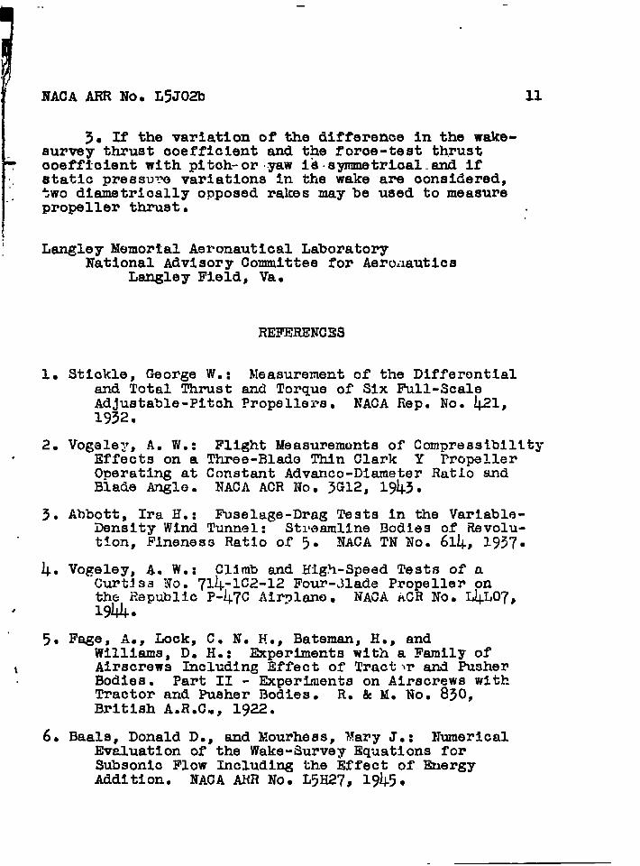
angle of rotation measured in direction of propellerrotation from vertical axis (fig. 1), degrees
APPARATUS AIKDMETHODS
tests were conducted in the Lai@ey 8-foot high-speed tunnel with a two-blade right-hand- r~peller 4 f=et
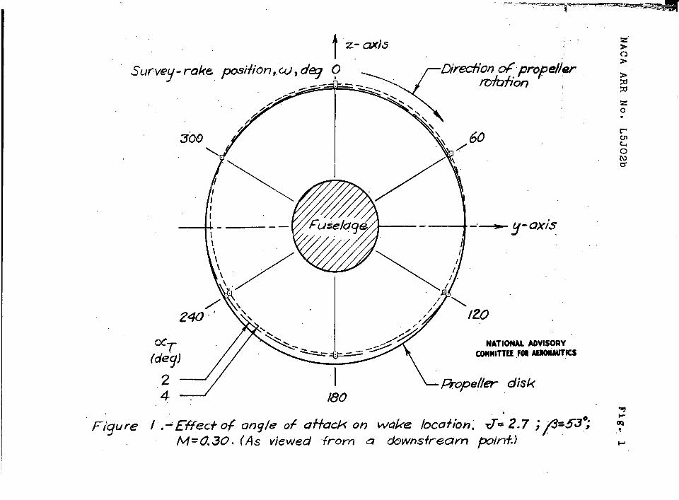
YIn diameter and having an NACA 4-(3.9)(07 -034-5-Bbladedesign of NACA 16-series sections.
Blade fom curves for the propeller are given Infigure 2. The propeller was designed to have a mtnlmumenergy loss In the wake. The pitch distribution used Inthe design of the propeller is that obtained by assumingall sections of the blades to be operating at the samefree-stream velocity. The design conditions were for afree-stream Mach number of 0.600, sn advance-dl,ameterratio of 2~70, and a power coefficient of 0.167.
—— —.

...-
4
The body on whichwas designed to have a
the propellerhigh crltloal
was teSted (fig. ~)Mach number. The
fuselage–shame was the NACA form 111. (See ref’erenoe3.)The wlfigof ~he model extended through the tunnel walls-andwas fastened to the balance ring. The airfoil had a20-inoh chord, was 9 percent thick, and had modifiedNACA 66-series sections.
The forward 7.4 percent of the fuselage was used asa spinner containhg the propeller hub. The propellerplane was located at 3.8 percent of the fuselage lengthto give a spinner diameter equal to 15 percent of thepropeller diameter. A small gap between the propellerand the spinner surface was sealed by sponge rubbercemnted to the blades In ofier that no radial outflow frmthe spinner along tho blades could occur.
The 200-horsepower induction motor used to turn thepropeller was 10 inches In dlemater and 30 inches longand was housed wlthtn the fuselage, The motor housingwas mounted on ball bearings coaxial with the shaft andwas prevented from rotating under the torque reaotlon bya hydraulic unit that transml.ttedthe torque force to asmle~ .
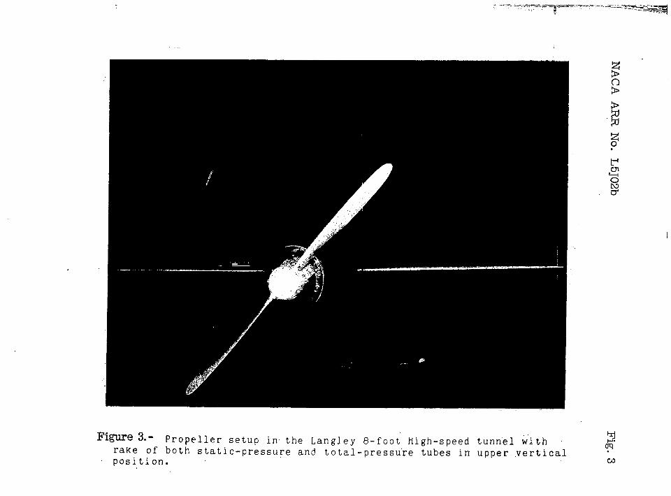
Thrust was measured simultaneously by force testsand by wake surveys. The force tests were made by use of’the tunnel drag balance, which gives the resultant forceon the model along the tunnel axis. Propulsive thrustwas computed as this resultant force plus the drag of themodel without the propeller, Far thrust measurementby wake surveys, a total-proasure survey rake was looatedradially In a plane per~ndlcular to the tunnel axis18 inches (0.375di~meter) behind the proneller plane andbolted to the tunnel wall. The effect 01 longitudinalposltlon of tho survey rake was net investlgated;thelongitudinal position used approximated that of the testsreported in reference 4. Complete tests were made for therake mountsd in each of the six equally spaced positionsaround the propeller disk, The rake was free of the modelat all ttmes and extended to within about 0.25 inch of thefu9elage surfaoe. The tubes of the rake were arranged tomeasure thG wake from radial stations of about 0035 to 1.15-Although the proneller wake was shifted at the survey stationby the fuselage, this arrangement providqd complete measure-ment of the thrust distribution on the blade for all condi-tions tested., The rake was connected to an incli.ned-$ubemanometer and the pressures were recorded photographically.
I

NACA ARR MO. L5J02b 5
The force-test data have been reduced to the usualm thrust-and power-coefficlentq~d. have been.cor~oted for
the equivalent free-stream velocity (ref’tiierioe5) and for “the buoyancy effect on model drag that occurs as a resultof tunnel-wall constraint.
Beoause of the constraint of the tunnel walls, theequivalent free-stream airspeed corresponding to thethrust and torque of the propeller measured at eachrotational speed differs from the tunnel datum velocity. f’This correction was evaluated by surveys of velocity hthree planes - immediately In front of, immediately behind,and at the propeller tip. The velocity surveys extendedfrom the tunnel wall to the propeller tip. The correctionwas evaluated from these data by the msthod of reference 50This correction, which was small, has been applied in thedetermination of the values of the advance-diameter ratio. “
Because of’the slipatreem contraction, ~he air passingoutside the slipstream wldorgoes an increase in staticpressure with distance downstream from the pronellor.This increase in static pressure gives rise to a buoyancyforce on the model. The measured thrust has been correctedfor the buoyancy ef~ect. The correction was determinedfrom measurements of the static-press~e gradient in thetunnel air stream. Theso maasure:nontswere made for thecomplete rang~ of thrust loading and Mach number coveredIn this test.
The wake-survey,thrust coefficient was computed from “measurements of static-pressure and total-pressure changesin the wake of the propeller. An explanation of the methodused is given in reference 6.
Data were obtained for blade angles of 260 and 530measured at the 0.75 radius; the propeller was tested at ablado angle of 26° at a free-stream Mach number of 0.30and a blade angle of 53° at free-stream Mach numbers of 0.30and O.~. The tests were made with the propeller thrustaxis at angles of’attack of 2° and ko for the lower Hachnumber and of 2° only for the higher Mach number because oflift-load limit. At an upper vertical rake position, testswere made at an additional thrust axis angle.of attack of 1°for a blade angle of 53°.
The data presented herein may be applied to propelleroperation In yaw by rotating the ruforenca axis from which
.
——
6 NACA’
the survev nosltion is”measured”throtuzh90°
AR@ NO. “~J02b -
or. throwzhthe appro~r~ate angle for conditions ~f 6ombtned plt~hand”yaw.
RES~TS AND DISCUSSION ,
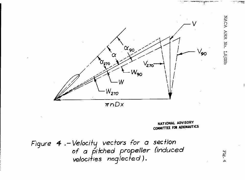
In computing the thrust coefficient from data obtainedwith a single survey rake, the ass~ntloi~ 1s made that no”variation in the flow about the propeller blade occursduring a revolution. In other words, it is assumed thatthe radial thrust distribution 1.sldentlcal for all angularpositions around the propeller disk and tinereforethatthe.survey-rake measurements are independent of rake posl-tlon. This condition exists only when the free-streamflow.is parallel to the propeller thrust axis and the bodyInterference on the propeller Is uniform about the thrustaxlso When tl~apropeller thrust axis is Inclined to theflow, each blade section operates at a varying angle ofattack as.it turns through a revolutions
If the propeller axis is at a positive angle ofattack and the propeller is operating at a constantadvance-diameter ratio, the blade sections in the righthalf of the disk for a right-hand propeller will have agreater angle of’attack than thoso in tho left half. Thisoondltlon Is illustrated by the vector diagram of.figure !+in which It 1s also evident that changes cccur In theresultant velocity of”the blade sectic?”ns.If the effectsof Induced velocity are noglectod,the forward velocityfor a section at a propeller-thrust-axis mgle of attackof 0~ and at an angular location. @ is shown by a solidline in figure $ with the resultant velocity W makhgan angle of attuck a with the section. If the propelleraxis is given a small positive ungle of attack with thefree-stream flow, a section with anguIar locations ofeither u = 0° or w= 18oo will have an insignificantchange in its angle of attack; but, as the section rotatesfrom w = 0°, Its angle of attack will increase to amaximum value at = 900, will return at ~ = 1800 tothe value for o =‘0°, and wI1l decrease to a minimum “value at u = 270° from which it w1ll increase to tb.eoriginal angle of attack at w= OO. ~Tho veloclty-veotor“diagrams for a section at maximurcand minimum angles ofattack are also shown In figure 4; the long-dash-linevectors represant the maximum condition at w = 900 nnd

NACA ARR No ● L5J02b 7
I
I the short-dash-line vectors the minimum oondltion at= 2700. At the.oonditi.ons.ofmaximum and minimum seo-
r ““t~on’angle”of attack,-’th& angles-between the original -and displaced forward-velocity vectors are equal to the
] propeller-thrust-axis angle of attack. These variations,. In section angle of attack and resultant velooity cause
an irregular wake. This Irregularity In the wake Isclearly the effect of Inclination of the propeller axisto the free-stream flow and Is not related to body lnter-ferenoe.
The pitched attitude of the propeller results in ashift of the wake relative to the fuselage. Figure 1,whiah shows the wake shift for angles of attack of 2°and 40, indicates that a rake located in the unper halfof the disk will measure more of the wake than a rakein the lower half.
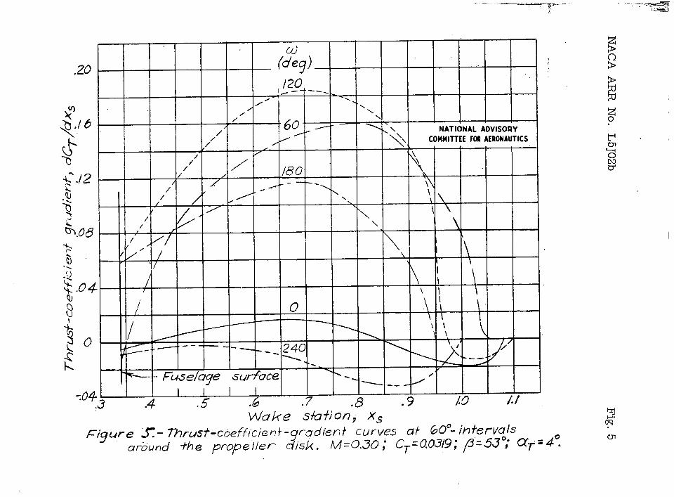
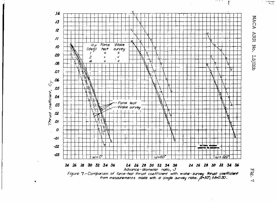
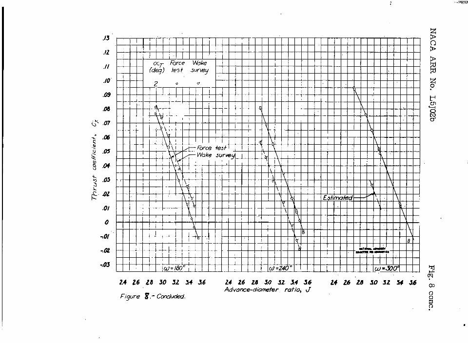
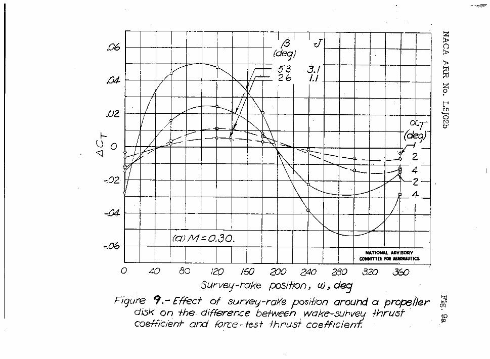
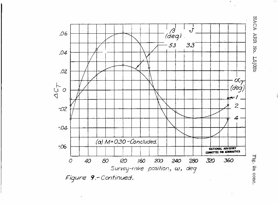
It is very evident that these wake irregularities “render a single survey rah” of little value for calcu-lating the propeller thrust coofficiont when tho thrustaxis is inclined to the direction of the free stream.The effect of the wake irregularities is illustrated infigure 5 in which thrust-coefficient-gradientcurves areshown at a constant propeller thrust coefficient forrake positions (with the exception of the 300° position)at 600-intervals for a blade angle of 53° and at anangle of attack of 4°. Very larga wahe changes areapparent. When the wake-survey thrust coefficient obtainedby integration of thrust-coefficient-gradientcurves isplotted for a range of advance-diameter ratio, ths curvasobtained oompare as shown in figures 6 to 8 with those of theforce-test thrust coefficient for the same conditions ofpropeller operation.
The change in thrust loading as the blade turnsthrough a revolution is shown in figure 9 as the differencebetween tho integrated wake-survey thrust coefficientand the force-test thrust coefficient at a constant tidvance-dlameter ratio as read from figures 6 to 8. Since the curvesIn these figures for the wake-survey and the force-testmeasurements ara nearly parallel, this plot will bepractically the same for the entire r,angoof advance-diameter ratio up to the point of stall.
From the section angle-of-attack variation of apitohed propeller, the curves of ACT would be expected
..
8 NACA AR.RNO. L5J02b
to pass through O at w = 0° and M= 1800 and theirpoints of maximum amplitude would be expected to be at(1)=900 ad M = 27000 Rotation of the propeller”wake;”however, causes a shift of the cqrves in the directionobserved, but this shift is of the order of only 30to 50. The large remainder of the shift is unaccountedfor but may be daused by the oscillation of the angleof attack of the blade sections with a resulting lag otsection fore’=swith angle-of-attac”~clwinges.
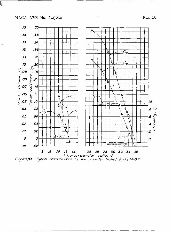
The curves of figure 9 show the amount by which thewake-survey thrust coefficient obtained by use of a singlerake may differ from the actual pro~eller thrust coeffl-clent. The difference between these thrust coefficientsfor the blade angle of 530 at aT = 4° mries to maximumvalues about 100 percent greater and 100 percent lessthan the thrust coefficient foi> maximum efficiency forthat blade angle, which may be read for aT = 20 fromfigune 100 Tho maximum difference for the low bladeangle of 260 at the same thrust-axis angle of attack isabo’~t40 percent greater and 40 psrcent less than thethrustmcoe~flcient for maximum efficiency at that bladeangle. At propeller thrust coofflcients smaller thanthose at maximum efficienc~, these percentages are, ofcourse, larger and, conv~rsely, at propeller thrust coef-flc:Lentsgreater than those at maximum efficiency, thepercentages are smaller.
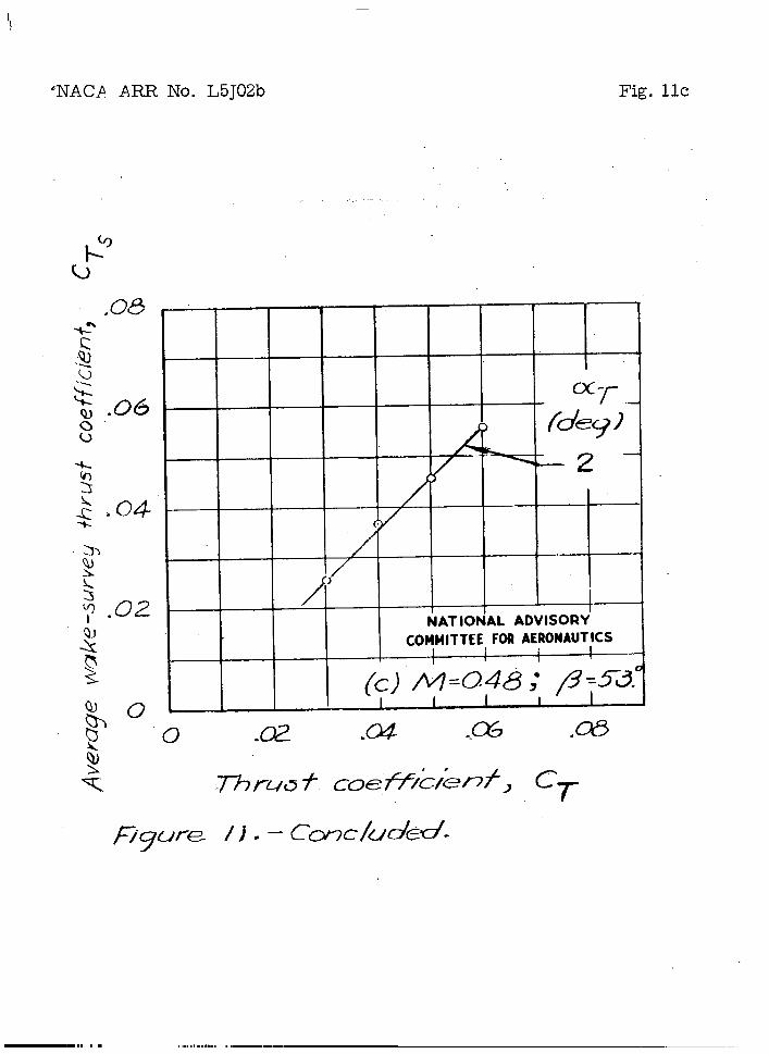
An average of measured wake-survey thrust coefficientsobtained from surveys made of tho irregular wake of apitched or yawed propeller by a numb~r of equally spacedrakes would be expscted to agree with the propeller thrustcoefficient more closely as the number of rakes isincreased. In figure 11 comparisons are presented ofthe average wake-survey thrust coefficient for all SIXrake locations with the corresponding force-test thrustcoefficient as read from the curves of’figures 6.to 8.At the thrust coefficient for msximwm efficiency, forthe blade un@e of 530,”the”average wake-survey thrustcoefficient Is about 6 percent lower than the pro eller
gthrust coefficient and, for the blado Gngle of 26 , thewake-survey measurement 1s ~bout 4 percent lower. Theseare the maximum values of the difference betwaen thepropeller thrust coefficient and tkw wakf”-surveythrustcoefficient at the thrust coefficient for maximum effi-ciency; this difference is primarily the result ofneglecting the static-pressura variation In the wake.
I
!“NACA ARR ~0, ~J02b 9
I!l!he”effeotof neglecting the static-pressure variationin.the wake..was detqmnin.edfrun tests with a rake of both‘static- and total-pressure tubes;- The Wrxke-surveythrust-.coefftoient was oaloulated by use of the uctual staticpressure along the rake and then recalculated with theassumption of free-stream static pressure along the rake.
‘k1, The curves of wake-survey thrust coefficient as calculalmd
by these two methods are presented in figure 12. At thethrust ooefficlent for maximum efficiency, the assumptionof free-stream static precsure Is shown, for both bladeangles, to cause the calculated wake-survey thrust coeffi-cient to be about 4..5peroent lower than that obtained bTuse of the actual pressure.
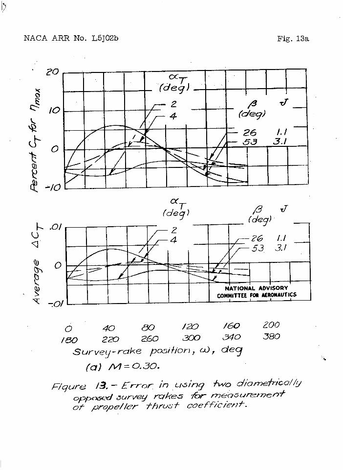
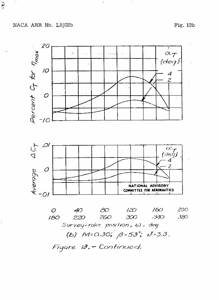
The syxmnetryof the ACT-CUI?VGSof figure 9 suggeststhat the average of the thrust coeff’lciontsfrom twodiametrically opposod rakes will be equal to the propellerthrust coefficient. The difference, at all points aroundthe disk, between force-test thrust coefficient and averagewake-survay thrust coefficient for two diametricallyopposed rakes is presented in figure 13. me curves wereobtained by averaging values of ACT at points 1800 “apart on the m.mves of figure 9 for positions all aroundthe disk nnd plottlng the values obtatned against rakeposition. These ourves dhow the luck of symmetry of theAcll-variat!on. Fzcept for the curva at the high blade~.ngleand ki~;.it“nrust.-a~.lsangle of attack, the curvesshow that an uvcrage of the wake-survey thrust coefficientsfrom two diametrically opposed rakes is lower than thepropeller thrust coofflcl.entby an mno~nt equal to O to5 percent of tinethrust coefficient for maximum ef’flclency.This difference indicates that the two-r~?ceinstallation willprove satisfactory when the static-pressure variation isIncluded in the calculations and whan the propeller is .operating under conditionssfinilarto those used harein~Two diametrically opposed ralms provide an average thrustooefflcient equal to the propeller thr~t coefficientbecause of the synnnetryof the ACT-curves; two diametrically’opposed rakes will therefore be insufficient in cases in wwhich these curves are nonsymmetrical, Nonsymmetricalbody interference around the propellor disk induced by ~thick Wi~S, large scoops, cockpit oanoples, or similarbodies will destroy the symmetry of.the ACT~ourVeS and sopreclude the use of only two rakes.
. ..
The recommended posltlons for an installation of twora!kes1s for several reasons at the points of maximum
1-—m Ilmll 1 l—. , —== , .

. .—.
10 NACA ~ No. L5J02TJ
and minimum loading: First, the early compressibil’ltyand stall losses at these points can be observed (refer-ence )+);second, the rate of change of ACT with radialrake posttlon is smaller near these points than at otherpositions; and last, the instal~ation is more praoticalfor-flight tests, in which the rakes should be mountedhorizontally because of larger changes In pitch than inyaw,
In two-rake installations in whichmthe rakes arenot radial to the propeller axis, the thrust obtainedfrom each rake wI1l correspond to that of a radial rakelocated in some position between the values of u forthe innermost and outermost survey tubes. If the twoequivalent radial positions for the two nonradial rakesintersect at an angle other than 18oo, the average ofthe two thrust values for those positions will be equal topropeller thrust only for the conditions of zero angle ofpitch and yaw. If the equivalent radial rake positionsoccur near the points of maximum amplltude of the hCT-curves.,however, the error of the nonradial installation w1ll beless than if’the equivalent positions occur near pointsof zero amplitude where the slope of the curves is stcapest,
CONCLUSIONS
From tests made to determine the effect of survey-ralkeposition around the disk of a pitched propeller onthe measurement of propeller thrust and to determine thedisposition md mlntimm number of rakes necessary tomeasure the’thrust, the following conclusions can bedrawn:
1. Propeller operation at small angles of pitch oryaw causes large variations in the distr-~?mtlonof energyin the wake.
2. Unless the propeller is opGrating at zero angleof Ditch or yaw and the body interference on the pro-peller 1s unlfonn about the thrust axis, one surveyrake is insufficient for cbtalning propeller thrustsince differences of more than 100 percent may occurbetween aotual thrust and thrust calculated from thewake-survey measurements.
I
1..NACA ARR No. L5J02b 11
/
3. If the variation of the difference In the wake-survey thrust ooefficlent and the foroe-test thrustooefffoient with pitch--oryaw Ia-symmetrical.and ifstatic pressul.mvariations In the wake are considered,,.two diametrically opposed rakes may be used to measure..propeller thrust.
Langley Memortal Aeronautical LaboratoryNattonal Advisory Comml.tteefor Aerrxlautlcs
Langley Field, Va.
REFERENCES
1. Stlck3e, George W.: Measurement of the Dlfferontialand Total Thrust and Torque of Stx Full-ScaleAdjustable-Pitch ?ropellei’s. NACA Rep. No. 4.21,1932.
2. Vogole;”,A. W.: Flight Measuremmts of Compressibility# Effects on a Three-Blado Thin Clark Y Propeller
Operating at Constant Advance-Diameter Rutlo andBlade fmgle. NACA ACR No. 3G12, 1943,
3. Abbott, Ira H.: fiselage-Drag Tests In the Variable-Density Wind Tunnel: Stlwamline Bodies of Revolu-tion, Fineness Ratio of 5. NACA TN NO. 614, 1937.
4. Vogeley, A. W.: Cllmb and High-Speed Tests of CL‘CurtflssNo. 714-1C2-12 Four-Jlade Propeller onthe Republic P-47C Airplane. NACA ACR No. ~L07,
. 1944.
5. Fage, A., Lock, C. N. H., Bateman, H., andWilliams, D. H.: Experiments with a Family of
\ Airscrews Including Effect of Tract~r and PusherBodies. Part II - Experiments on Airscrews withTractor and Pusher 130dies. R. & M. No. 830,Brltlsh A.R.C., 1922.
6. Baals, Donald D., and Mourhess, I!aryJ.: NumericalEvaluation of the Wake-Survey Equations forSubsonic Flow Including the Effect of IZuergyAddition. NACA ARR No. L5H27, 1945,
—.=.._——> _. _.. _~l,.;:L ....-2=_~ .--——.
t“.Z-cxisSurvey- rake pi+ion,.u, + O
“. “ .;--/f-+KDir”’’%or’e”r
/zo
‘7 /r+=-f NATIONAL AOVISORY
(deglCOMITTEEFORAEMwmcs
-J’2 _-/I ~ R-ope/h disk
4. /80
zo.
1-
NACA ARR No. L5J02b Fig. 2
.8
.56\ \ CL G
.6 ;-QI..u.-
.4 :\
L IO, II IIY II Illhl
I
$EEl+i
w
52 ;< ‘Ill llhll 1111. .
G
48
-Q u I \.-.z h \
:.08 ---4— — b/D _ _ ‘---
-Qc1 NY
G\ \
.04 \\ ~
44
0 ./ .2 .3 .4 ..5 .6 .7 .8 .9 [0Blode–section station, x
Figure Z. - NA CA 4 -(39Y07) -0.345-B ~ro~elier blade - &v-m cuwes.
.—
z0.
Figure3.- Propeller setup in the Lang”ley 8-foot Iiigh-speed tunnel w“ithrake of both static-pressure and total-pressure tubes in upper verticalposition, co
—.=.=-. -. =p=’---” ““==3
7-V
TnDx
Figure 4. – Veloci{y vec+ors for aof a pi iched prope/le~velochs ~+ecte d )”
v90
NATIONAL ADVISORY
COMMITTEEFORAERONAUTICS
sec +)on(induced
——.. ~=..—-# ““”’--725
w’
,20(d+,1204./- —-- .
0’ .N
/ \/ \
{./ 6 ; /‘ -60- -/ / \ NATIONAL ADVISORY
!!J/’ k’ ,/ ‘ COMMITTEEFORAERONAUTICS
//. ,
/’//
$’.12/8o
/ /\\
4 “ \ \\.? // @ \/ \ \q d / \ \/k.o~ / f \ \,> / / // \b’ // / \\.. /
/I“$.04 I \/ \ I
~ / o \II \
— — ~ \+ 1
\ \p \ \ 4/ ,-. \ /
~ - —--- ~ 0f --/
. . ,- Fuse/oge wrfuce
\. 0
~ ._ _/704.3 ‘ I I I I
.4 .5 .6 .7 .8 .9 m LIWake Shf;onj Xs
~igwe X- ?Zwusf-coefficie n +-gradien I cLJwes at 60°- ifl~erv:lsaround the propeller disk. M=Q30; cT=@3{9; ~=53 ; af= 4?
1
w6.Cn

z!s
+ hcC7- firce Mb@ >
(deg) *+ ‘PY b~ if
\ ) o 4
k
o d !5\
\’d: ~. \ b
i
~I.
i\ ryi \\ \. , u-l
\\ ,
\
~’l’,\\\\ u’
f1?;,? ‘Ji\ \l
~
1~\\ Q \~‘
~ \! \\
\’\r \
\ ~\ \l
\!:\..\t,\ \\ I \
\\? ~,ik
\( \\!
JI\ \l
\\ y~‘i.
,\\\\ i, \ \,
,‘,\
\, \ \\ \‘~,\\, \ \ \
\& ,h
o\ l\ \
= 60” w ’12PU=oc w cd=I&O”NATIONAL ADVISORY
ICOMITTEE M ~Ks j!’
Ao & “14Lo 12 1.4/0 kz /.4 do /2 [4 Lo kz 14 ki kzAdvonce - diQmehr rc7t)o, C7
figure 6. - Comp@on 0+ f&ce-+e# +hrus+ coefficient wi# wake - surkt%j A&us+ coefficientYw.
from measurements made witi a sihgle survey rake . ~=26°;, IW=O.3Q.(m.0
*
“J4
./3
.J2
./1
.10
.09
.07
0
70/
F ‘W@-’alwl’mm~uf
llllll~lllllli’111(.4)=0° (.4.. ,-1=/20°
1 I 1 , 1 I 1 1 1 I r ,
L).em” I I Itl
24 2h 28 30 32 34 36 24 2.6 24 30 32 34 d6 z4z62a JO J23436Advance -d&nekr rwtio, J
Figure 7.- Cornpwison of fwce- test ihrus+ coefficien+ with wake- surve #YL# tom%’clenf
1from rne~urgmeh+s tie with a. .YngkI survey rake. +3? MxO.30.

\ u -==
.13.
.12
./1
.10
.09
.08
; .03
:.02
.01
0
-.01
?02
-.03
Advame-dlam4wr” roiio, JFigure 7.-Concluded.
%i-.m.

.13
.12
.It
.10
.09
.08
$. .033$ ,02h
.01
0
?01
702
+3
I
24 26 28 30 32 34 36 24. 26 28 30 32 34 36 24 26, 28 SO 32 34Adwmce -diamefw ratio, J
Figure #!- Conpmkon of fmce -fast thn& coefflcleni wih wake -surwy #m.M coefficientfrom measuremti & wlh u single wrvey roke. /3.s3 “; M=o.4e.
.13
.12
.11
Jo”
.09
$ .03~
& .02
.01
0
.01
-.02
?03
2.4 26 28 30 12 34 36 24 26 28 30 32. .X4 36 24 26 “28 30’32 34 J6Advoxe-diometer. rotio, J
Figure g. - Cmchdad.
zo.
.
.06
.a4
.02
702
-.05
/
/
.
/1
/’
(a) M’=0.30.~ /
NATIONAL ADVISORY
COMMITTEEfORAERONAUTS
I
o 40 80 120 /60 ZO Z40 280 320 36(2 “
iWveg-mke psifion, cd, deg
Figu~ 9.- Efkct of surve~-rafe podioo arounddbk on +he difference bejwen wake-amve
?coefficient+ ati @Ke - hs f fhtwst Coefficient .
.
.06
.04
.(2Z
1----C_.)o
~
-02
:04
1
[3! — ‘/JJ’/(dey)
/— 53 3.3
/
//
/~ \ /
\,/
I
/ \
// ‘x .’ a
I\ - (deg~
(> 4-./ _1( I \ / ) Z_
/
t ~ 4–
/.
(a) M= 0.30-Concluded.1 I
NATIOtk mls~y
CONNl~EE FORAEMMWKS
o 4om 120 I(5U X0 240 280 320 =
S urve~-rahe posiilon, U, de~
Fiyure 9.- Continued.
zo.
coP

v
z>
‘.06
.04
.02
J oQ
<(
:02,
-.04
T06
/3 TJtiey)
\ A~ 53 a. I
/ ~ W-/
,(d+
\/ d> /\ , : z
‘T /
(b)[email protected] ADVISORY
COMMITTEE FOA AERDNAUTKS
040/?0 /20 /60 faozmm~~61wvey-rake position, w, o’eq
Fiqure 9.– Concluded.
3.
II
NACA ARR NO. L5J02b Fig. 10
./5
.14
./2
.I’l
./0
1-
.04
.03
.02
.01
0
701
.02
0
.02
I
L’- 7
-o-- +---l.- -0
—-c—
10
.8
.6
.4
.2
0
.6 .8 Lo [2 /.4 24 2!6 2.8 .30 32 34 36Advarce - diameter rufio, J
Figure /0.- Tipicul ctwrz+erkfics for fhe prop.4/er i-esfed. &T=2,?M =(230.
—

IJ.
No. L5J02b
.
Fig. lla
NATIONAL ADVISORY
COMMITTEE FOR AERONAUTICS
(d [email protected];/6=zG:
I I

II—
t
NACA ARR No. L5J02b
bq
Fig. llb .
+-
$ .02 I 1
NATIONAL ADVISORY
COMMITTEE FOR AERONAUTICS
.02 .04 .08
1,
WACl! ARR No. L5J02b Fig.llc
,,
‘—.. ,,,,, ,,.,,,,,,..., , ,,—--—

Advance - diome~r rafjo, d
Figure /..-The effect on woKe-survey #Wst co@7’/cient of.Wream s+atic pressure alon~ +he survey
jhe aSWnption of free-rake. M =0.30.
I
.
1
1’*,/
NACA AR,R No. L5J02b Fig. 13a
Zo
/0
o
-/0
o
70/
i I 1 I I I I t
cY—P
J
NATIONAL ADVISORY
ICOMMITTEE FORAERONAUTICS
J
/.I3. ~
1.
(u) M = 0.30.
$ ‘-
NACA ARR No. L5J02b Fig. 13b
20
1- .0/LJ ‘T
(cl!+ _4
/ ‘ C2/
-eI
NAT IONAL ADVISORYCOMMITTEE FORAERONAUTICS
o m m I= i~ 200
/80 220 260 am CMo .380
Survey- rake pow lion , d , deg
(bj M=03Q; “/3=3-30; L7=3.3.
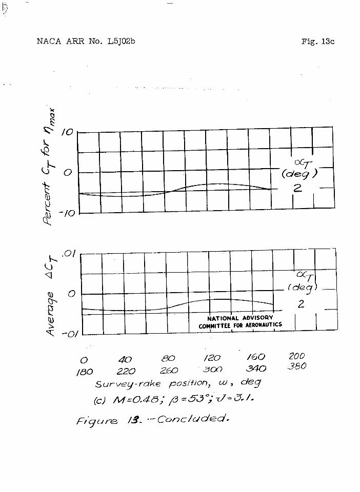
NACA AR.R No. L5J02b Fig. 13c
.,, ... –... . .
,
— “cx-f
(d+ —
/- 2
NATIONAL ADVISORY,
COMMITTEE FORAERONAUTICS●
1
0 40 /20 ‘ /60 200180 220 z~ 305 .360
s ut-~~ey-r-ake positioti, w , dq
(c) /w=o.40; p =53 °;”T7=a /.
F+] re .13- “- cone/cdfd.

..— . — I
?
‘ *.J . . ,
.