b.h.v. topping (editor), modelling of sequential casting...
TRANSCRIPT

1
Abstract In this paper, we present computer simulation results of foundation concrete slab behaviour in an early stage. The Künzel and Kiessl`s model was used to analyze heat and moisture fields and was extended by a set of climatic conditions and by a model of hydration heat evolution in concrete. The isotropic damage model was used together with the B3 model for description of concrete mechanical behaviour. The problem was solved using program SIFEL. The code was extended by the implementation of the sequential construction using time controlled switching on/off of particular degrees of freedom. This extension affected results significantly. Keywords: coupled problems, isotropic damage, anisotropic damage, foundation slabs, creep, concrete. 1 Introduction Using of the foundations slabs for large structures is relatively common case. The foundation slabs have significant thick in such cases and the problem with casting arises due to hydration heat generation. Apposite numerical models have to be used for the validation of the designed casting procedure. One of the possible numerical models was implemented in the SIFEL code. This software package can solve heat and moisture transport problems and mechanical problems by the finite element method. Additionally, the coupled problems from the above fields can be solved. It is programmed in the C++ language and its source codes are free.
Casting procedure of the foundation slab can be solved as a coupled thermo-hydro-mechanical problem in this software. The Künzel and Kiessl`s models are at disposal for the simulation of the heat and moisture transport processes. The Bazant’s B3 model can be used for the description of concrete creep and shrinkage, damage can be modelled by the scalar isotropic damage model. The subsoil under the foundation slabs had to be modelled by the system of spring supports due to the complexity of the computation process. The stiffness of the springs can evolve
Paper 115 Modelling of Sequential Casting Procedure of Foundation Slabs T. Koudelka, T. Krejčí and J. Šejnoha Centre for Integrated Design of Advanced Structures Faculty of Civil Engineering Czech Technical University in Prague, Czech Republic
©Civil-Comp Press, 2007 Proceedings of the Eleventh International Conference on Civil, Structural and Environmental Engineering Computing, B.H.V. Topping (Editor), Civil-Comp Press, Stirlingshire, Scotland

2
nonlinearly depending on settlement of the foundation slab. Another possibility of the subsoil model represents using of the full 2D or 3D subsoil model, but this approach would increase the computation time too.
Several important modifications of SIFEL code were performed on basis of experiences from the previous analyses performed in 2006 year. These modifications improved simulation of the real process of the casting procedure. First of all, the code was extended by the implementation of the sequential construction using time controlled switching on/off of particular degrees of freedom. In addition, it was implemented and successfully used numerical solution of the B3 model using a continuous retardation spectrum method. A new solver of time dependent problems was implemented and used. The solver contains Newton-Raphson iteration method which significantly improved results.
A scalar damage model was modified to respect time variability of Young modulus and tensile strength and correction of dissipated energy depending on the size of element was implemented. Advanced models of anisotropic damage were theoretically derived and partially implemented. Mentioned methods were used for the 2D model of cranked foundation slab which was cast in three layers. The behaviour was solved as coupled problem in which the mechanical behaviour was assumed together with heat and moisture conduction and their interactions. Material parameters were obtained from the project of foundation slab of commercial building in Prague-Těšnov.
2 Modelling of sequential casting procedure It showed that the exact model of the real casting procedure is crucial for the correct results. It is not possible to use zero or very low Young modulus with respect to B3 model complexity. This leads to implementation of the switching on/off of particular structure parts with help of time controlling code numbers change in the mesh nodes. This approach is probably the best possible way how to describe sequential building of the structure, because the parts, which have not been cast, are not assumed in the computation. 2.1 Mechanical behaviour Concrete exhibits very complicated mechanical behaviour and many material models were developed to describe it. But most of them can capture only one or several attributes of this behaviour and this leads to combination of these models.
The decomposition of the total strain in the material point to the particular components is the base of the computations with several different material models describing different attributes of the mechanical behaviour. In described cases, the following decomposition of the total strain is used
εtot = εe + εd + εcr + εshr + εft, (1)

3
where: εtot is a total strain εe is an elastic component of strain εd is a strain component due to damage of concrete εcr is a creep component of strain εshr is a shrinkage component of strain εft is a free temperature strain
Creep and shrinkage effects of concrete together with free temperature strains
have significant effect to the total strain which is decisive for evolution of cracks. The B3 model can be used for creep and shrinkage modeling, details about this model can be found in [7, 8]. Both effects are included in it and they are temperature dependent. The original numerical solution of B3 model was based on Dirichlet series and it was found too slow for purposes of the given coupled problem and that is why the continuous retardation spectrum method was implemented. Detailed description of the above method can be found in [14].
Quite a number of material models were developed describing damage of concrete. Taking into account that the computing coupled problems is extremely time consuming, the simple scalar isotropic model have been used. The model is dependent on sizes of mesh elements and it dissipates different energy for the various mesh elements density. This was the reason for the rewriting of the model and the variable softening modulus technique was employed, which partially suppress this fault. The method consists in that the strain due to damage is assumed in the following form
hw
el =− = εεεd , (2)
where w is the crack opening and h is a characteristic size of element and ε is
defined as follows
)( ftshrcrtot εεεεε ++−= (3) During damage evolution, the stress can be formulated depending on the crack
opening w
⎟⎟⎠
⎞⎜⎜⎝
⎛=
ft w
wf expσ , (4)
where ft denotes tensile strength of concrete and wf is the initial crack opening
which is treated as a material parameter. The stress can be written for scalar isotropic damage in the following form
εωσ elD)1( −= . (5)

4
Equations (3), (4) and (5) can be combined and assuming εel as
Eelσε = (6)
the resulting nonlinear equation can be written for the damage parameter ω.
( ) ⎟⎟⎠
⎞⎜⎜⎝
⎛−=−
ft w
hfE εωεω exp1 (7)
Equation (7) was derived for the uniaxial stress state assumption and it is
necessary to replace strain ε by the equivalent strain εeq for other cases. Equation (7) is nonlinear and it can be solved by Newton method. Detailed description of the variable strain softening technique can be found in [10].
Models for creep and viscosity are time dependent and they were solved by the Perzyna approach. In this approach, the vector of unbalanced internal forces in the given time step is added to the load vector in the next time step. Combination of the time dependent material models (B3) with the models designed for a nonlinear statics (damage, plasticity) caused numerical instability which was due to unbalanced forces. The original method based on the Perzyna approach does not offer good potentiality for the iteration of equilibrium. The vector of unbalanced forces is added to the vector of load in the next time step and that means the iteration is dependent on the size of time step and this can lead to the improper results. These difficulties can be solved by addition of the Newton-Raphson iteration method which establishes equilibrium with a required error for nonlinear statics models in particular time steps.
The scalar isotropic damage model can be used for case of uniaxial tension quite successfully. The computation of this model is very fast and this was the reason for its using in the given coupled problem. The model has only one damage parameter ω and that is why damage evolution in one direction reduces stiffness in rest directions. It introduces certain inaccuracy especially for changing to a 3D model. Employing much more effective method for B3 model (continuous retardation spectrum) creates space for application of a more robust damage model.
An anisotropic damage model represents one possible way of damage modelling. The base of this model was described in [13]. Following damage parameter and two independent damage tensors were established:
d - volumetric damage parameter introduced only for tension tD - damage tensor for damage induced by tensile strains cD - damage tensor for damage induced by compressive strains
The model assumes splitting of the elastic strain tensor into its tensile and compressive parts
ct eee += (8)

5
where te (respectively ce ) is a strain tensor having the same positive (respectively negative) eigenvalues as e and vanishing remaining eigenvalues. They can be expressed as:
∑∑==
−−==III
Iji
cij
III
Iji
tij nneennee
α
ααα
α
ααα ; (9)
where the index α denotes principal direction, ⋅ are Macauley brackets and
αin are components of eigenvectors of e . The model is derived form the elastic
potential which was slightly modified in the volumetric part compared to the original proposed in [13]. The following expression is obtained assuming above equations for Helmholtz free energy
( )( )[ ] ( ) ( )( ) ( ) 1D1eD1
1D1eD1
:
:2323
2/12/1
2/12/122
ccc
tttvolvolel
G
GdGK
−−+
−−+−−= εερψ (10)
where K is bulk modulus, G is shear modulus, volε is the volumetric strain and 1
is the second order identity tensor. Damage driving forces conjugated to d, tD and cD can be derived from Equation (10) by its derivation with respect to damage
parameters:
( ) tttelt G ee
DY =
∂∂
−=ρψ , ( ) cc
celc G ee
DY =
∂∂
−=ρψ , ( ) 2
29
volel K
dy ερψ
=∂
∂−= (11)
The tensors tY and cY have the same principal directions as e and by
consequence, both tD and cD also have the same directions. These forces have the form of potential energy of the appropriate part of the strain tensor i.e. deviatoric and volumetric respectively. Evolution of principle damage components of tensors
tD and cD is controlled by load functions which are defined by Equation (12).
( ) ( )[ ] 01/11 0 ≤−−+−= βββαβ
βα
βα
BYEYADf (12) where the index α denotes principal direction, the index β can be either t or c,
and A, B are material parameters ( 1,0 ≥≥ BA ), E is the Young modulus and 0Y is a threshold value of the given non-dimensional damage driving force.
( ) ( )[ ] 01/11 0 ≤−−+−= byEyadf (13)
Similarly, evolution of volumetric damage is controlled by the load function described by Equation (13), where a, b are material parameters and 0y is a threshold value of the non-dimensional volumetric damage driving force. Introduced load

6
functions define elastic domains for their negative values and no evolution of damage occurs in these domains. When the given damage force is on boundaries of domain ( 0=f ), damage components evolves. Note that the damage components can be increased only and their values have to be in range <0, 1>, where 0 means no damage and 1 means full damage.
Components of principal stresses ασ can be obtained from Equation (10) by derivation with respect to e and the transformation to principal directions:
( ) ( )( )[ ] ( )( ) ( )[ ] αααααα εεεεεσ ct
volvol DHDHGHdGK −−−+−−= 12123 (14)
where ( )⋅H is Heaviside function. Correct energy dissipation depending on the
element size can be derived similarly as for the scalar isotropic damage model. Dissipation is defined by
∫∞ •
=0
dtDYD (15)
and the dissipation can be related with fracture energy fG
DG f h= (16)
where h is a characteristic element length. Rewriting Equation (15) for one
principal damage component and substituting time derivations from Equation (14) leads to the integral
( )
( )[ ]∫∞ −
−+
−=
0
2
0
10
1YB
B
dYYYAE
YYBAYD (17)
After integration, the final relation is obtained depending on fracture energy,
element size and material parameters A, B for particular principal directions and tension or compression
ABBE
EY
hG
B
f =
⎥⎥⎥⎥
⎦
⎤
⎢⎢⎢⎢
⎣
⎡⎟⎠⎞
⎜⎝⎛
⎟⎟⎠
⎞⎜⎜⎝
⎛−
−
π
πsin0 (18)
More details about obtaining of material parameters of the anisotropic damage
model can be found in [13].
7
3 Results form performed analyses Thermo-hydro-mechanical coupled problems are extremely time consuming and that was the reason for using only 2D problem although the program can solve also the 3D problems and all material models are derived for 3D too. Computations are slowed down not only by the complex material models but also by necessity of a relatively fine mesh and short time steps. The solution of the given problem takes about one day on a computer with Pentium 4 on 3.2 GHz frequency. Approximately, two days of structure real existence are computed during this time. It is caused by two factors. The first factor significantly increasing computing time is evolution of hydration heat during the first several hours and it implies necessity of fine time steps during this time. The second factor is evolution of damage due to shrinkage caused drying and due to temperature strains. Evolution of damage means that the unbalanced internal forces have to be iterated in the Newton-Raphson method. After finishing major part of a hydration process when hydration heat is not generated, the time step can be increased during the computation and consequently, it increases speed for the rest computation significantly.
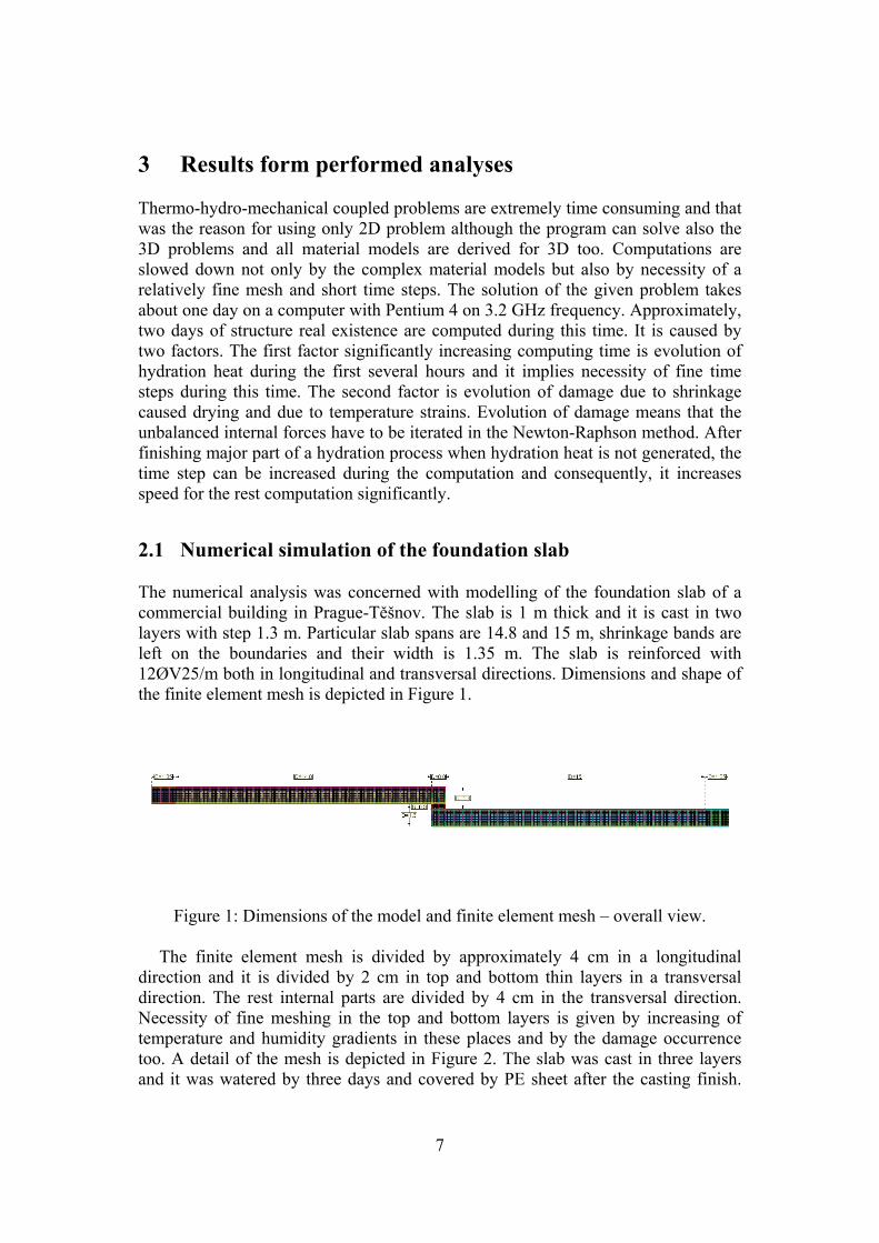
2.1 Numerical simulation of the foundation slab The numerical analysis was concerned with modelling of the foundation slab of a commercial building in Prague-Těšnov. The slab is 1 m thick and it is cast in two layers with step 1.3 m. Particular slab spans are 14.8 and 15 m, shrinkage bands are left on the boundaries and their width is 1.35 m. The slab is reinforced with 12ØV25/m both in longitudinal and transversal directions. Dimensions and shape of the finite element mesh is depicted in Figure 1.
Figure 1: Dimensions of the model and finite element mesh – overall view. The finite element mesh is divided by approximately 4 cm in a longitudinal
direction and it is divided by 2 cm in top and bottom thin layers in a transversal direction. The rest internal parts are divided by 4 cm in the transversal direction. Necessity of fine meshing in the top and bottom layers is given by increasing of temperature and humidity gradients in these places and by the damage occurrence too. A detail of the mesh is depicted in Figure 2. The slab was cast in three layers and it was watered by three days and covered by PE sheet after the casting finish.

8
The plane-strain model of the slab was assumed. The computer simulation begins at 1 hour after the casting finish of the first layer. In the performed thermo-hydro-mechanical analysis, Künzel-Kiessl model was used for modelling of transport processes, B3 model and scalar isotropic damage model were used for the description of the mechanical behaviour. The slab was supported by spring supports on the bottom and stiffness of springs on the edges was increased in order to capture of subsoil behaviour. The slab was loaded by dead weight and thermal boundary conditions were applied. These thermal conditions simulated average temperature in June and they were obtained by the long-term measurements in the given locality.
Casting of particular slab spans was performed in three layers which were sequentially turned on in the model by 1 hour from the casting finish.
Figure 2: Detail of finite element mesh. Following pictures depict resulting courses of stresses (Figures 3-8), damage
parameter (Figures 9-11) and deformed shape of structure (Figures 12-14) for particular construction stages of the lower slab. For first two layers, results are depicted at time close to casting of the next layer; results for the third layer are depicted at time 15 hours after casting of the first layer. Figures 15-17 represent detailed view on the character of damage for left corner, middle and right corner respectively. The course of damage is captured on these figures after 15 hours form the casting finish of the first layer.
More accurate image about the damage parameter evolution can be obtained form the graph in Figure 18. This figure depicts comparison of damage parameter evolution history in the top left corner, middle of the slab and the top right corner respectively.

9
Figure 3: Stresses σx for one layer of concrete after 4 hours form the casting.
Figure 4: Stresses σx for two layers of concrete after 7 hours from the casting.
Figure 5: Stresses σx for three layers of concrete after 15 hours from the casting.

10
Figure 6: Stresses τxy for one layer of concrete after 4 hours form the casting.
Figure 7: Stresses τxy for two layers of concrete after 7 hours from the casting.
Figure 8: Stresses τxy for three layers of concrete after 15 hours from the casting.

11
Figure 9: Distribution of the damage parameter ω for one layer of concrete after 4 hours form the casting.
Figure 10: Distribution of the damage parameter ω for two layers of concrete after 7 hours from the casting.
Figure 11: Distribution of the damage parameter ω for three layers of concrete after 15 hours from the casting.

12
Figure 12: Deformed shape of structure with course of total displacements for one layer of concrete after 4 hours form the casting.
Figure 13: Deformed shape of structure with course of total displacements for two layers of concrete after 7 hours from the casting.
Figure 14: Deformed shape of structure with course of total displacements for three layers of concrete after 15 hours from the casting.

13
Figure 15: Detail of the distribution of damage parameter ω for three layers of
concrete in the top left corner of the slab after 15 hours from the casting.
Figure 16: Detail of distribution of the damage parameter ω for three layers of
concrete in the middle of the slab after 15 hours from the casting.

14
Figure 17: Detail of distribution of the damage parameter ω for three layers of concrete in the top right corner after 15 hours from the casting.
0
0,2
0,4
0,6
0,8
1
0,00 2,00 4,00 6,00 8,00 10,00 12,00 14,00 16,00
time [h]
ω [-]
Top left corner Middle of the slab Top right corner
Figure 18: History of evolution of the damage parameter for three characteristic
domains of the slab.
3 Conclusions and future development Results of the analysis confirmed that the precise modelling of the sequential construction is very important for damage parameter evolution. Resulting distribution of the damage parameter can be viewed in Figure 11. The distribution corresponds approximately to time 15 hours from the casting finish of the first

15
bottom layer of the low slab. In Figure 16, it can be seen on the detailed view that the bottom layer is damaged to 20 cm depth. Maximal damage parameter value is about 0.4. This damage is caused by the hydration process in the top layer which is delayed compared to bottom layers. During the peak of hydration heat generation in the top layer, the slab is deformed by the reason of non-uniform heating and it has tendency to deflect up. The bottom layer is than damaged in the middle as a result of dead weight load. Details about the deformed shape can be seen in Figure 17.
Climate conditions are another important factor causing damage. It can be recognized in Figures 15-17 that all top surface of the slab is damaged but only to the low depth. This damage is caused by drying shrinkage which is amplified by applied climate conditions. The top right corner and the slab front were last significantly damaged areas. Damage was caused by shear stresses and it can be seen in Figures 8 and 17.
From the future development point of view, the described anisotropic model should be used in analysis and probably better description of damage should be obtained. On the other hand, demands on memory and computer speed will be very high. Acknowledgements This outcome has been achieved with the financial support of the Ministry of Education, Youth and Sports of the Czech Republic, project No. 1M0579 References [1] R.W. Lewis, B.A. Schrefler, “The finite element method in static and dynamic
deformation and consolidation of porous media”, John Wiley & Sons, Chichester-Toronto (492), 1998.
[2] G. Pijaudier-Cabot, L. Jason, “Continuum damage modeling and some computational issues”, RFGC – 6/2002, Numerical Modelling in Geomechanics, p. 991-1017, 2002.
[3] B. Sluys, “Constitutive modeling of concrete and nonlinear computational dynamics”, RFGC – 7-8/2003, Geodynamics and Cycling Modelling, p. 911-973, 2003
[4] R. de Borst, P. Nauta, “Non-orthogonal cracks in a smeared finite element model”, Eng. Comp., 2(1), p. 35-46, 1985.
[5] Z.P. Bazant, T.B. Belytschko, T.P. Chang, “Continuum theory for strain-softening”, ASCE J. Eng. Mech., 110, p. 1666-1692, 1984
[6] G. Pijaudier-Cabot, Z.P. Bazant, “Nonlocal damage theory”, ASCE J. Eng. Mech., 113, p. 1512-1533, 1987
[7] Z.P. Bazant, S. Baweja, “Creep and Shrinkage Prediction Model for Analysis and Design of Concrete Structures – Model B3”, RILEM Recommendation, Mater. Struc., 28, p. 357-365, 1995
[8] Z.P. Bazant, S. Baweja, “Justification and Refinements of Model B3 for Creep and Shrinkage. Updating and Theoretical Basis”, Mater. Struc. 28, 1995, p. 44-50, 1995
16
[9] Z. Bittnar, J. Šejnoha, “Numerical methods in structural mechanics”, ASCE Press USA and Thomas Telford UK, 1996
[10] M. Jirásek, “Numerical Modeling of Deformation and Failure of Material”, Czech Technical University, Prague, 1998
[11] M. Jirásek, Z.P. Bazant, “Inelastic Analysis of Structure”, John Wiley & Sons, Chichester-Toronto, 2001
[12] F. Larrard, “Concrete mixture proportioning”, E&FN SPON, 1999 [13] E. Papa, M. Telierico, “Anisotropic Damage Model for the Multiaxial Static
and Fatigue Behaviour of Plain Concrete”, Engineering Fracture Mechanics, Vol. 55, No. 2, Elsevier Science Ltd., 1996
[14] Z.P. Bažant, W. Xi, “Continuous retardation spectrum for solidification theory of concrete creep”, J. Engrg. Mech., 121(2), 281-288, 1995