bht-206a/b-mm ch 28
DESCRIPTION
BHT, Bell, Helicopter, Maintenance, Manual, Overhaul, 206, A/B, B, B3, BIII, Swashplate, inspectionTRANSCRIPT
BHT-206A/B-SERIES-MM-4
28-00-0013 OCT 2011 Rev. 11 Page 1ECCN EAR99
TABLE OF CONTENTS
Paragraph Chapter/Section Page Number Title Number Number
CHAPTER 28 — FUEL SYSTEM
28-1 Fuel System (Helicopter S/N 4 Through 3566) .............................. 28-00-00 328-2 Fuel System (Helicopters S/N 3567 and Subsequent) .................. 28-00-00 328-3 Safety Precautions.................................................................... 28-00-00 328-4 Troubleshooting ........................................................................ 28-00-00 328-5 Operational Check .................................................................... 28-00-00 328-6 Testing ...................................................................................... 28-00-00 328-7 Fuel Cells (Helicopters S/N 4 Through 3566) ................................ 28-00-00 828-8 Fuel Cells (Helicopters S/N 3567 and Subsequent) ...................... 28-00-00 828-9 Removal (Helicopters S/N 4 Through 3566)............................. 28-00-00 828-10 Fuel Cells — Removal
(Helicopters S/N 3567 and Subsequent) .................................. 28-00-00 1228-11 Inspection and Repair............................................................... 28-00-00 1328-12 Cleaning.................................................................................... 28-00-00 1328-13 Installation (Helicopters S/N 4 Through 3566).......................... 28-00-00 1428-14 Installation (Helicopters S/N 3567 and Subsequent) ................ 28-00-00 15
FUEL DISTRIBUTION
28-15 Fuel Distribution ............................................................................. 28-00-00 1728-16 Fuel Pump and Filter Assembly ..................................................... 28-00-00 1728-17 Fuel Boost Pump ........................................................................... 28-00-00 1728-18 Removal.................................................................................... 28-00-00 1728-19 Inspection ................................................................................. 28-00-00 1728-20 Installation................................................................................. 28-00-00 1728-21 Fuel Pump Cartridge...................................................................... 28-00-00 2428-22 Replacement — Fuel Pump Cartridge in 206-062-673-001
Pump ........................................................................................ 28-00-00 2428-23 Replacement — Fuel Pump Cartridge in 206-062-681-101
Canister Type Fuel Boost Pump............................................... 28-00-00 2528-24 Replacement Fuel Pump Cartridge in 206-062-681-103
Pump, Canister Type ................................................................ 28-00-00 2628-25 Fuel Shutoff Valve.......................................................................... 28-00-00 2628-26 Removal (Helicopters S/N 4 Through 153)............................... 28-00-00 2628-27 Installation................................................................................. 28-00-00 2628-28 Removal (Helicopters S/N 154 Through 3566)......................... 28-00-00 2928-29 Installation (Helicopters S/N 154 Through 3566)...................... 28-00-00 2928-30 Removal (Helicopters S/N 3567 and Subsequent) ................... 28-00-00 2928-31 Inspection ................................................................................. 28-00-00 2928-32 Installation (Helicopters S/N 3567 and Subsequent) ................ 28-00-00 2928-33 Fuel Pressure Transducer ............................................................. 28-00-00 2928-34 Removal.................................................................................... 28-00-00 2928-35 Inspection ................................................................................. 28-00-00 2928-36 Installation................................................................................. 28-00-00 2928-37 Fuel Quantity — Indicating Units ................................................... 28-00-00 2928-38 Removal.................................................................................... 28-00-00 3028-39 Installation................................................................................. 28-00-00 30

BHT-206A/B-SERIES-MM-4
28-00-00Page 2 Rev. 11 13 OCT 2011 ECCN EAR99
TABLE OF CONTENTS (CONT)
Paragraph Chapter/Section Page Number Title Number Number
28-40 Drain Valve .................................................................................... 28-00-00 3228-41 Removal.................................................................................... 28-00-00 3228-42 Installation................................................................................. 28-00-00 3228-43 Solenoid Valve ............................................................................... 28-00-00 3228-44 Removal.................................................................................... 28-00-00 3228-45 Installation................................................................................. 28-00-00 3228-46 Cap ................................................................................................ 28-00-00 3228-47 Removal.................................................................................... 28-00-00 3228-48 Installation................................................................................. 28-00-00 3228-49 Filter Element Change Requirement.............................................. 28-00-00 3528-50 Removal and Installation 206-706-603 Filter Element.............. 28-00-00 3528-51 Removal and Installation 52-2889-016 or 52-3889-016A
Filter Element............................................................................ 28-00-00 3528-52 Removal and Installation 222-366-621-101 Filter Element....... 28-00-00 3528-53 Airframe Mounted Fuel Filter ......................................................... 28-00-00 3528-54 Airframe Mounted Fuel Filter — Removal ................................ 28-00-00 4128-55 Airframe Mounted Fuel Filter — Inspection .............................. 28-00-00 4128-56 Airframe Mounted Fuel Filter — Installation ............................. 28-00-00 4128-57 Engine Fuel Filter........................................................................... 28-00-00 41
FIGURES
Figure Page Number Title Number
28-1 Fuel System........................................................................................................ 528-2 Fuel System........................................................................................................ 728-3 Fuel System Schematic ...................................................................................... 928-4 Fuel Boost Pump ................................................................................................ 1828-5 Modification of Fuel Boost Pumps ...................................................................... 2328-6 Fuel Shutoff Valve............................................................................................... 2728-7 Fuel Pressure Transducer .................................................................................. 3028-8 Fuel Quantity Indicator Units............................................................................... 3128-9 Drain Valve ......................................................................................................... 3328-10 Solenoid Valve .................................................................................................... 3328-11 Cap and Adapter Assembly ................................................................................ 3428-12 206-706-603 Fuel Filter Assembly ...................................................................... 3628-13 52-2889-016 or 52-2889-016A Fuel Filter Assembly .......................................... 3728-14 222-366-621 Fuel Filter Assembly ...................................................................... 3828-15 Airframe Mounted Fuel Filter Assembly.............................................................. 39
TABLES
Table Page Number Title Number
28-1 Troubleshooting Fuel System ............................................................................. 4

Q..
,=«
--I
-=o
0 0
c`°
omO
moo
(On
0,-
.
300
300 (O
D
0)->>
'
+,r
+-.
°c)
0
E
00-±
...
000
OL
C0)-
E
>-E
>
B HT-206A/B-SERIES-M M-4
FUEL SYSTEM
28-1. FUEL SYSTEM (Helicopter S/N 4through 3566).
The fuel system (figure 28-1) incorporates a singlebladder type fuel cell located below and aft of thepassenger seat (figure 28-1). Installed within the fuelcell are two electrically operated boost pumps, lowerand upper tank indicating unit and sump drain valve.Boost pumps are interconnected and supply fuelthrough a single hose assembly to the fuel shutoff valveand from the shutoff valve to the engine mounted fuelfilter and pump. Boost pumps incorporate pressureswitches in discharge ports and drain plugs in the pumpdrain port. The fuel cell is filled from the right side andhas a capacity of 76 U.S. gallons (287.66 liters usable).
Access to boost pumps, lower tank unit and drain valveis from the bottom of fuselage and access to upperindicating unit is gained from a cover plate located ondeck aft of passenger seatback. Access to fuel shutoffvalve and vent line is in the fuel compartment located onthe right side of access panel above filler cap.Provisions are also made in fuel compartment forcombustion heater fuel, fuel pressure instrument line,and fuel pump purge line.
28-3. SAFETY PRECAUTIONS.
1. All fueling and defueling operations should beperformed in an area where fire hazards are reduced toa minimum.
2. Handle fuel cells with extreme care during removaland installation to prevent damage to cells. Do notattempt to remove or install a cold fuel cell.
3. Helicopter must be grounded prior to performingdefueling operations.
28-4. TROUBLESHOOTING.
Refer to Chapter 96 for fuel quantity calibration, fuel filterand fuel pump electrical circuitry. Refer to figure 28-3 forfuel system schematics. Refer to table 28-1 fortroubleshooting.
28-5. OPERATIONAL CHECK.
Refer to Chapter 96 for fuel filter, fuel flow switch, lowfuel pump caution systems operational checks.
28-6. TESTING.
1. With throttle off and shutoff valve on, connect airsource to vent line.
28-2. FUEL SYSTEM (Helicopters S/N 3567and subsequent).
The fuel system (figure 28-2) incorporates a singlecrash resistant bladder type fuel cell located below andaft of the passenger seat. Installed within the fuel cell aretwo electrically operated boost pumps, lower and uppertank indicating unit and electrically operated sump drainvalve. Boost pumps are interconnected and supply fuelthrough a single hose assembly to the fuel shutoff valve,and from shutoff valve to the airframe mounted fuel filter.Boost pumps incorporate pressure switches in
discharge ports and drain plugs in pump drain ports. Thefuel cell is filled from the right side and has a capacity of91 U.S. gallons (344.44 liters usable).
Access to boost pumps, lower tank unit and solenoiddrain valve is from the bottom of fuselage and access toupper indicating unit is gained from a coverplate locatedon deck aft of passenger seatback. Access to fuelshutoff valve and vent is in fuel compartment located onthe right side above filler cap. Provisions are made in thefuel compartment for a fuel purging line to be installedat tank vent fitting for maintenance purposes.
cAUT10N
DO NOT APPLY MORE THANRECOMMENDED PRESSURE ASDAMAGE TO FUEL SYSTEM ANDSTRUCTURE MAY RESULT. USE MILDSOAP SOLUTION TO LOCATE LEAKS.
NOTE
Use regulated low pressure from filtered,compressed air source with accuratepressure gage, and a shutoff valve.
2. Slowly apply pressure until gage indicates 0.75 to1.00 psig (5.17 to 6.89 kPa). Shut off air source. The fuelsystem should hold this pressure for 15 minutes.
3. Alternate Method: Using a water manometer,test to a reading of 20.76 to 27.68 inches (527.30 to703.07 mm) of water. The fuel system shall hold thisreading for 15 minutes.
4. Locate and correct any leakage indicated. Repeatpressure test if leaks are found.
5. Remove test equipment from vent line.
28-00-00Page 3

BHT-206A/B-SERIES-MM-4
28-00-00Page 4 Rev. 8 30 JUN 2010 ECCN EAR99
Table 28-1. Troubleshooting Fuel System
INDICATION OF TROUBLE PROBABLE CAUSE CORRECTIVE ACTION
Engine fails to light off Insufficient fuel in cell Fill cell with correct fuel.
Insufficient or no fuel pressure to engine pump
Turn on boost pumps and fuel shutoff valve.
Boost pump inoperative Check pump per Chapter 96. Replace pump if required.
Fuel contaminated Refer to applicable Rolls-Royce Operation and Maintenance Manual.
Defective shutoff valve, or valvefails to operate when selected
Replace valve. Refer to Chapter 96.
Fuel quantity system not indicating or has incorrect reading
Defective boost pump, tank indicating units, or electrical malfunction
Refer to Chapter 96.
Fuel quantity/pressure circuit breaker
Check and replace breaker.
Loose circuit connections Tighten connections.
Defective indicator Replace indicator.
Improper resistance setting on R5 or R6
Check resistance and calibrate system.
Defective tank unit system Replace tank unit and recalibrate system.
No pressure, fuel pressure gauge fluctuates or has erratic readings
Air trapped in fuel boost pump Bleed boost pumps. Refer to paragraph 28-20, step 13.
Transducer failure Replace transducer.
Fuel pump caution light on Defective boost pump, cartridge, or fuel pressure switch. Defective boost pump check valves.
Replace pump, cartridge, or switch (Chapter 96). Replace check valves.
Fuel filter caution light on Clogged filter See note .
Boost fuel pumps fail to operate when breaker is closed or circuit breaker trips
Electrical malfunction Refer to Chapter 96.
NOTES :
1. Inspect fuel cell for contamination. Clean cell as required to remove all contaminants. Drain sump until allwater is removed. Remove the line at the filter inlet and direct it into a bucket. Using the boost pumps, pump twogallons of fuel through the lines to purge out any additional water. Reconnect the line to the filter.
2. Install a new airframe filter element.
3. Refer to applicable Rolls-Royce Operation and Maintenance Manual for further action.
1
1
BHT-206A/B-SERIES-MM-4
28-00-00Page 6 Rev. 8 30 JUN 2010 ECCN EAR99
Figure 28-1. Fuel System (Sheet 2 of 2)206AB_MM_28_0001b
1.
2.
3.
4.
5.
6.
7.
8.
Fuel shutoff valve
Tee
Fuel cell
Upper tank unit
Aft fuel boost pump
Lower tank unit
Drain valve
Check valve
9.
10.
11.
12.
13.
14.
15.
16.
Forward fuel boost pump
Hose
Hose
Cap and adapter assembly
Fitting
Tube
Vent tube
Filter
1
2
Helicopters S/N 004 through 2123 must upgrade fuel purge system per SL206A-100,
in accordance with ASB 206-05-103.
Helicopters S/N 004 through 3566.
NOTES
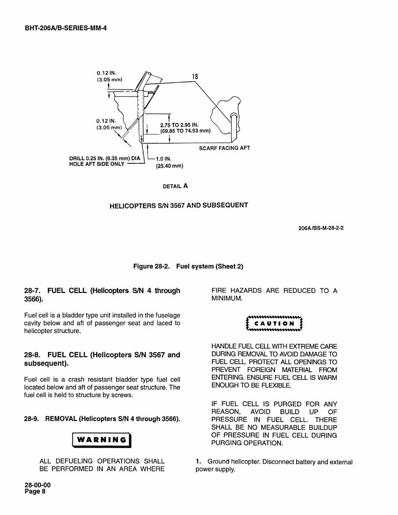
DETAIL A
DETAIL B
SCARF FACING
FORWARD
VIEW LOOKING
FORWARD
2.75 TO 2.95 IN.
(69.85 TO 74.93 mm)
0.12 IN.
(3.05 mm)
0.12 IN.
(3.05 mm)
2
FWD
FWD
2
1514
14
2
ors
BHT 206A/B-SERIES-MM-4
1. Airframe fuel filter2. Hose3. Fuel cell4. Upper tank unit5. Aft fuel boost pump6. Lower tank unit7. Solenoid drain valve8. Check valves9. Forward fuel boost pump
10. Hose11. Hose12. Cap and adapter assembly13. Tube14. Fuel shutoff valve15. Hose16. Clamps 12
17. Tube18. Tube19. Fuel cell
attachment20. Screws
15
HELICOPTERS S/N 3567 AND SUBSEQUENT
Figure 28-2. Fuel system (Sheet 1 of 2)
206A/BS-M-28-2-1
28-00-00Page 7
0G)
-°u)
LC
)
BHT 206A/B-SERIES-MM-4
0.121N.(3.05 mm)
I
0.121N. I A I
IDRILL 0.25 IN. (6.35 mm) DIA ) 1.0 IN.HOLE AFT SIDE ONLY
DETAIL A
(69.85 TO 74.93 mm)
18
2.75 TO 2.95 IN.
SCARF FACING AFT
HELICOPTERS S/N 3567 AND SUBSEQUENT
206A/BS-M-28-2-2
Figure 28-2. Fuel system (Sheet 2)
28-7. FUEL CELL (Helicopters SIN 4 through3566).
Fuel cell is a bladder type unit installed in the fuselagecavity below and aft of passenger seat and laced tohelicopter structure.
28-8. FUEL CELL (Helicopters S/N 3567 andsubsequent).
Fuel cell is a crash resistant bladder type fuel celllocated below and aft of passenger seat structure. Thefuel cell is held to structure by screws.
28-9. REMOVAL (Helicopters S/N 4 through 3566).
WARNING
ALL DEFUELING OPERATIONS SHALLBE PERFORMED IN AN AREA WHERE
FIRE HAZARDS ARE REDUCED TO AMINIMUM.
HANDLE FUEL CELL WITH EXTREME CAREDURING REMOVAL TO AVOID DAMAGE TOFUEL CELL. PROTECT ALL OPENINGS TOPREVENT FOREIGN MATERIAL FROMENTERING. ENSURE FUEL CELL IS WARMENOUGH TO BE FLEXIBLE.
IF FUEL CELL IS PURGED FOR ANYREASON, AVOID BUILD UP OFPRESSURE IN FUEL CELL. THERESHALL BE NO MEASURABLE BUILDUPOF PRESSURE IN FUEL CELL DURINGPURGING OPERATION.
1. Ground helicopter. Disconnect battery and externalpower supply.
28-00-00Page 8
ww
B HT-206A/B-SERIES-M M-4
-ENGINE
PURGELINE-CHECK VALVE NOTINSTALLED ONHELICOPTERS S/N 254THRU 660, AND 672THRU 715 -
PURGE LINEON HELICOPTERS SIN 254THRU 660,AND 672 THRU 715
DRAIN VALVEPRESSUREDIFFERENTIALSWITCH
HELICOPTERS S/N 4 THROUGH 660, AND 672 THROUGH 715
206A/BS-M-28-3-1
Figure 28-3. Fuel system schematic (Sheet 1 of 3)
28-00-00Page 9

RESTRICT OR
NSTgLLED ONHELICOPTS/N 661 THRRS671, 716 THRU2058 VENT
PRESSURESWITCH- I ORASOLEIV010
IVALVE
FUELCAUTION
LIGHTLIGHT
LER LPRESSURE GAGE
i'iEllCppTERS SAN 667 THROUGH 67,, AND 676 THROUGH 2211
206q/BS-M_28.3.2
Figure 28-3. Fuel system schematic (Sheet 2)
- PRESSURE
FUEL
VENT
AIRFRqFILTER ME MOUNTED
SHUTOFF VALVE

-c
I-
-10 z
-1-ii c z
zc
m c m
zz Um r
m
z
}-
B HT-206A/B-SERIES-M M-4
ENGINE
HELICOPTERS S/N 2212THRU 3566 PRESSURESWITCH
FUEL FILTERCAUTION
LIGHT GRAINVALVE-HELICOPTERS S/N 2122THRU 3566
............................
PRESSURE
FUEL
VENT
--AIRFRAME MOUNTEDFILTER
SHUTOFF VALVE
FUEL PRESSURE GAGE
FILLERFUEL CAPTANK
ENGINE FUEL PUMPAND FILTER
SUMPPRESSURE hl1 i- PRESSURE
SWITCH
FUEL PUMP -JCAUTION
LIGHT
HELICOPTERS S/N 2212 AND SUBSEQUENT
20fiA1BS-M-28-3-3
Figure 28-3. Fuel system schematic (Sheet 3)
2s-oo-ooPage 11
BHT-206A/B-SERIES-MM-4
28-00-00Page 12 Rev. 11 13 OCT 2011 ECCN EAR99
2. Defuel and purge fuel system (Chapter 12).
3. Remove seat cushions and seat backs(Chapter 25).
4. Remove panel from fuel compartment located onright side above cap and adapter assembly (12,Figure 28-1).
5. Remove cap and adapter assembly (12)(paragraph 28-47).
6. Disconnect electrical connections from upper andlower tank units (4 and 6) and aft and forward fuelboost pumps (5 and 9).
7. Disconnect hose (10) from two check valves (8).Remove hose through pump mount opening.
8. Remove hose (11) from fitting (13). Remove hosefrom fuel cell (3).
9. Remove aft fuel boost pump (5) (paragraph28-18).
10. Remove lower tank unit (6) (paragraph 28-38).
11. Remove forward fuel boost pump (9) (paragraph28-18).
12. Remove drain valve (7) (paragraph 28-41).
13. Remove upper tank unit (4) (paragraph 28-38).
14. Remove fuel shutoff valve (1) (paragraph 28-26,paragraph 28-28, or paragraph 28-30 as applicable).
15. Remove tubes (14 and 15).
16. Remove tee (2).
17. Collapse fuel cell (3) and remove nylon cordsattaching fuel cell to structure. Remove fuel cellthrough seat opening.
28-10. FUEL CELLS — REMOVAL(HELICOPTERS S/N 3567 ANDSUBSEQUENT)
WARNING
ALL DEFUELING OPERATIONS SHALLBE PERFORMED IN AN AREA WHEREFIRE HAZARDS ARE REDUCED TO AMINIMUM.
CAUTION
HANDLE FUEL CELL WITH EXTREMECARE DURING REMOVAL TO AVOIDDAMAGE TO FUEL CELL. PROTECT ALLOPENINGS TO PREVENT ENTRY OFFOREIGN MATERIAL. MAKE SURE FUELCELL IS WARM ENOUGH TO BEFLEXIBLE.
IF FUEL CELL IS PURGED FOR ANYREASON, AVOID BUILD-UP OFPRESSURE IN FUEL CELL. THERESHALL BE NO MEASURABLE BUILD-UPOF PRESSURE IN FUEL CELL DURINGPURGING OPERATION.
1. Disconnect battery and external power supply.Ground helicopter.
2. Defuel and purge fuel system (Chapter 12).
3. Remove seat cushions and seat backs(Chapter 25).
4. Remove access panel from fuel compartmentlocated on right side above cap and adapter assembly(12, Figure 28-2).
5. Remove cap and adapter assembly (12)(paragraph 28-47).
6. Deleted.
7. Deleted.

BHT-206A/B-SERIES-MM-4
28-00-00
ECCN EAR99
8. Disconnect electrical connections from upper andlower tank units (4 and 6), aft and forward fuel boostpumps (5 and 9), and solenoid drain valve (7).
9. Remove upper tank unit (4) (paragraph 28-38).
10. Remove lower tank unit (6) (paragraph 28-38).
11. Remove solenoid valve (7) (paragraph 28-44).
12. Remove hose (11) from fuel shutoff valve (14)and check valve (8).
13. Remove clamps (16), hose (15), and tubes (17and 18).
14. Remove fuel shutoff valve (14) (paragraph 28-26,paragraph 28-28, or paragraph 28-30 as applicable).
15. Remove hose (10) from two check valves (8).
16. Remove forward fuel boost pump (9) (paragraph28-18).
13 OCT 2011 Rev. 11 Page 12A/12B


O_'
(CD
0
(On
3(D
f?)
`<<
= (CD
c 0
cm°
C-0-
a)-w_0
a)~
0-0
U3:
.'-
ca-
17. Remove aft fuel boost pump (5) (paragraph28-18).
18. Remove five fuel cell attachment screws (20)attaching fuel cell (3) to structure. Collapse fuel cell andremove through seat opening.
28-11. INSPECTION AND REPAIR.
1. Field repairs are permitted on fuel cell in all areasexcept any radius, any fitting area, or to any cut or tearlonger than 1 inch (25.40 mm). Cells with damagebeyond these limits should be returned to the fuel cellmanufacturer for repair at one of the addresses listed inthe following paragraphs.
2. Inspect fuel cell to determine manufacturer (markedon the fuel cell). Repair kits, complete with all materialsand instructions for making field repairs, are availablefrom the respective cell manufacturers.
a. Order RK-30S repair kit, from Uniroyal Inc., 312N. Hill Street, Mishawaka, Indiana, 46544.
b. Order SK-2180-2, repair kit, from FirestoneCoated Fabrics Co., Division of Firestone Tire andRubber Company, 1200 Firestone Parkway, Akron,Ohio, 44317.
c. Order repair kit, number 2F1-3-42165, (ManualAP 30), from Engineered Fabrics Corporation,Rockmart, Georgia 30153.
3. Inspect fuel cell immediately prior to installation fordamage which may have occurred during crating orremoval from shipping container.
4. Inspect fuel cell for leaks after installation. Refer toparagraph 28-13, step 16.
5. Store fuel cells in original shipping containers atroom temperature. Do not store fuel cells where they willbe subjected to heat or extremes of humidity.
6. Handle fuel cells carefully to avoid damage.Observe the following precautions:
a. Leave fuel cells in original shipping containersuntil ready to install in helicopter.
b. Do not drag cells or pick up by fittings. Transportcells on carts. If a cell must be transported outsideinstallation area, place it in original shipping containers.
c. Do not handle cell with sharp pointed tools.
B HT-206A/B-SERIES-M M-4
d. Do not place cells on any surface with sharpprojections which could damage cell.
e. Do not stack cells except in original shippingcontainers.
f. Do not handle cells when they are too cold to beflexible.
g. Do not allow cells to remain in strong light anylonger than absolutely necessary. Do not allow lightbulbs to contact cell. Fluorescent inspection lights arerecommended for use in fuel cells.
28-12. CLEANING.
Bladder fuel cell may have accumulated heavy fungusgrowth due to contaminated fuel and may require thefollowing recommended procedures.
NOTE
Bladder fuel cell construction used in the206B helicopter has buna coated fabric innerplies. The buna rubber may be attacked tosome degree by micro-organism action.Degree of attack is very minor.
1. Remove fuel cell. Refer to paragraphs 28-9 or28-10.
2. Presence of fungus in fuel cell is usually caused byimproper servicing and storage of jet fuels. To helpalleviate problem of fungus in cells, suitable filters andwater traps should be used in fuel storage tank complexand servicing equipment.
NOTE
A fuel additive meeting the requirement ofspecification MIL-1-27686 and approved bythe FAA as PFA-55MB is recommended tobe added routinely to the helicopter fuel cellwhile refueling. This is same as anti-icingadditive recommended in applicableJetRanger Flight Manual. (Phillips productdistributed as 'Prist' meets this requirement.)Usually one treatment of PFA-55MB isadequate to kill bacteria and inhibit regrowthin fuel cell for some time.
3. If evidence of fungus is present in fuel cell,contamination is usually present in fuel filter and thehousing should be thoroughly cleaned, and the filterelement replaced.
28-00-00Page 13
4r-
CO
ED =^O
-0s ._
«3=
.c
Cop
)
z7°
(OD
=at
e
JD_4
m
a_0
0>7D
Om
<p0000)00
0-2
E0t5
6.s
L=L
F-g
..'
-'2
BHT 206A/B-SERIES-MM-4
4. Remove all fungus growth from fuel cell by hand orwith a soft scrub brush using warm or hot water.
TAPE (C-456). ENSURE THAT FUEL CELLIS WARM ENOUGH TO BE FLEXIBLE.
CAUTION CAUTION
IF HOT WATER IS USED TO CLEAN FUEL DO NOT FOLD A COLD FUEL CELL.CELL, IT IS RECOMMENDED THAT FOLDING MAY CRACK OR DAMAGE ATEMPERATURE OF HOT WATER BE COLD FUEL CELL. HEAT LAMPS MAY BELIMITED TO 160°F (71-C). HOTTER USED TO WARM FUEL CELL PRIOR TOWATER CONSTITUTES A HAZARD TO FOLDING. HEAT FOR APPROXIMATELY 2PERSONNEL. HOURS, DO NOT EXCEED 125°F (52°C).
DO NOT USE SOAPS OR STRONG NOTEDETERGENTS WHEN CLEANINGFUEL CELL. CERTAIN POWERFUL Either 206-061-675-001 or 206-061-675-DETERGENTS ARE DETRIMENTAL TO THEBUNA TYPE RUBBER AND SOAPS CANREACT WITH FUEL TO FORM ACOMPOUND WHICH TENDS TO PLUG FUELFILTERS.
5. When fungus is observed in fuel cell area, wipe thecell clean with cloths moistened with methyl alcohol(C-302). Burn wiping cloths after cleaning to destroyfungus.
CAUTION
003 fuel cell may be used.
1. Warm fuel cell (3, figure 28-1) as required. Applytalcum powder to fuel cell cavities.
2. Insert collapsed fuel cell (3) through seatbackopening and position forward section of fuel cell underseat.
3. Lace bottom aft side of fuel cell (3) to fuselagestructure using nylon cord. Tie nylon cord to right aftlower structure fitting and lace through seven deltahangers and fittings. Secure end of nylon cord on leftside.
UNDER NO CIRCUMSTANCES SHALLM ETHYL- ETHYL-KETON E (C-309) ORSIMILAR SOLVENTS BE USED FORCLEANING FUEL CELL.
6. Turbine fuels (C-003) may be used to advantage forcleaning fuel cells. Turbine fuels are oily and assist inprotecting cell inner liner against aging if cell remains outof service for several weeks without fuel.
28-13. INSTALLATION (Helicopters S/N 4 through3566.)
CAUTION
INSPECT FUEL CELL CAVITY FORFOREIGN OBJECTS BEFOREINSTALLATION OF FUEL CELL. EXERCISEEXTREME CAUTION TO PRECLUDEDROPPING OF TOOLS, HARDWARE, ETC.IN FUEL CELL CAVITY. ENSURE THAT ALLSHARP EDGES, CORNERS AND RIVETHEADS ARE PROTECTED WITH VINYL
4. Lace top aft side of fuel cell (3) to fuselage structureusing nylon cord. Tie nylon cord to right top structurefitting and lace through seven delta hangers and fittings.
5. Lace top forward side of fuel cell (3) to fuselagestructure using nylon cord. Tie nylon cord to rightforward structure fitting and lace through eight deltahangers and fittings. Loosely tie off nylon cord at laststructure fitting. Allow sufficient slack to provide handroom for installation of fittings on top of fuel cell.
6. Lace right and left forward sides of fuel cell (3) tofuselage structure using nylon cord. Tie nylon cord tofittings and lace through three delta hangers and fittings.
7. Lace bottom forward side of fuel cell (3) to fuselagestructure using nylon cord. Tie nylon cord to structurefitting and lace through seven delta hangers and fittings.
8. Install fitting (2) with tubes (14 and 15).
9. Install fuel shutoff valve (1) (paragraph 28-27,28-29, or 28-32) as applicable.
10. Install upper tank unit (4) (paragraph 28-39).
28-00-00Page 14

2Q- (O0
CD
-
DH
'
cn-<
mz
r>0
m
O)-
E
ZQ
wo(n
cam
iii
0
.....
coma
CIO
E
o
c>5
`15E
OM
11. Install drain valve (7) (paragraph 28-42).
12. Install forward fuel boost pump (9) (paragraph28-20).
13. Install lower tank unit (6) (paragraph 28-39).
14. Install aft fuel boost pump (5) (paragraph 28-20).
15. Install hose (10) to two check valves (8).
16. Connect electrical connections to forward and aftfuel boost pumps (9 and 5), and upper and lower tankunits (4 and 6).
17. Inspect fuel cell (3) installation for security.
18. Perform leak test on fuel cell (3) as follows:
a. Disconnect fuel vent tubes (14 and 15) from tee(2). Connect air source to tee. On helicopter S/N 154and subsequent disconnect line (15), install cap on tee(side port) and connect air source to top of tee.
CAUTION
DO NOT APPLY MORE THANRECOMMENDED PRESSURE. DAMAGETO FUEL CELL AND STRUCTURE MAYRESULT. USE A MILD SOAP SUDSSOLUTION TO LOCATE LEAKS.
NOTE
Use regulated low pressure, filtered,compressed air source, an accurate pressuregage, and a shutoff valve.
b. Apply pressure until gage indicates 1.0 psi(6.895 kPa). Shut off air source. Fuel cell should holdthis pressure for 15 minutes.
c. Alternate Method: Using a water manometer,test to a reading of 22.76 to 27.68 inches (527.30 to703.07 mm) of water. The fuel system shall hold thisreading for 15 minutes.
c. Locate and correct any leakage indicated.Repeat test if leaks are found.
d. Remove test equipment. On helicopters S/N 154and subsequent, remove cap from tee (2) and connecttubes 14 and 15.
19. Install fuel cell (3) access panel on seat support.
B HT-206A/B-SERIES-M M-4
20. Install coverplate on aft deck above passengerseatback.
21. Install seat cushions.
22. Connect battery.
28-14. INSTALLATION (Helicopters S/N 3567 andsubsequent).
CAUTION
INSPECT FUEL CELL CAVITY FORFOREIGN OBJECTS BEFOREINSTALLATION. EXERCISE EXTREMECAUTION TO PRECLUDE DROPPING OFTOOLS, HARDWARE, OR OTHER FOREIGNMATERIAL INTO FUEL CELL CAVITY ORFUEL CELL.
DO NOT FOLD A COLD FUEL CELL.FOLDING MAY CRACK OR DAMAGE ACOLD FUEL CELL. HEAT LAMPS MAY BEUSED TO WARM FUEL CELL PRIOR TOFOLDING, HEAT FOR APPROXIMATELY 2HOURS. DO NOT EXCEED 125°F (52°C).
1. Apply talcum powder into fuel cell (3, figure 28-1)cavities and insert collapsed fuel cell through seatbackopening. Work fuel cell in place and install five fuel cellattachment screws (20, figure 28-2).
2. Install screws securing cap and adapter assembly(12) to fuel cell (3) (paragraph 28-48).
3. Install forward fuel boost pump (9) (paragraph28-20).
4. Install aft fuel boost pump (5) (paragraph 28-20).
5. Install solenoid drain valve (7) (paragraph 28-45).
6. Install hose (10) to two check valves (8).
7. Install fuel shutoff valve (1) (paragraph 28-27,28-29, or 28-32 as applicable).
8. Install tubes (17 and 18), hose (15), and clamps(16).
9. Install lower tank unit (6) (paragraph 28-39).
10. Install upper tank unit (4) (paragraph 28-39).
11. Connect electrical connections to solenoid drainvalve (7), forward and aft fuel boost pumps (9 and 5),and upper and lower tank units (4 and 6).
28-00-00Page 15

BHT-206A/B-SERIES-MM-4
28-00-00Page 16 Rev. 11 13 OCT 2011 ECCN EAR99
12. Deleted.
13. Inspect fuel cell (3) installation for security.
14. Perform leak test on fuel cell (3).
15. Install fuel cell access panel on seat support.
16. Install coverplate on aft deck above passengerseat back.
17. Install seat cushions.
18. Connect battery.

0
0
C1)
0
-,o
0-0
3-0
-'"a
Q-0
((D 0
.-.
0 0
3(Q
'
g-0
`-D
c(<
00
((D
D
.O-.
0
v_0a.0
(Q)
,.,,
fl;a0)
E
B HT-206A/B-SERIES-M M-4
FUEL DISTRIBUTION
28-15. FUEL DISTRIBUTION.
Fuel distribution consists of all fuel cell mountedcomponents which transfer fuel, and monitor fuelquantity, fuel flow, or fuel pressure.
28-16. FUEL PUMP AND FILTERASSEMBLY.
The engine fuel pump and filter assembly are integralunits mounted on the aft end of engine. Fuel entersengine fuel system at inlet port of the pump and passesthrough filter before entering gear elements of pump.Filter draining is accomplished by a drain valve mountedon filter housing. Fuel filter is monitored by a pressuredifferential switch located on lower firewall andconnected electrically to fuel filter caution light. Refer toAllison Engine Company Operation and MaintenanceManual (5W2 for C-18 engine or 10W2 for C-20 engine)for detailed maintenance instructions.
1. Disconnect battery and defuel helicopter (Chapter12).
2. Disconnect electrical wiring to forward or aft pumps(6, figure 28-4).
3. Remove eight bolts (11) with seven washers (12)and ground lead from fuel pump.
4. Lower forward or aft pump (6) and disconnectattached fuel supply hose (2) or interconnect hose (1),as applicable and remove pump.
5. Cover fuel cell opening to prevent entrance offoreign material.
6. Remove check valve (4), plug (8), and pressureswitch (9). Discard all packings (5, 7, and 10).
28-19. INSPECTION.
28-17. FUEL BOOST PUMP.
Two electrically operated fuel boost pumps are locatedin the bottom of fuel cell. Pumps are interconnected andfurnish fuel through one supply line. Pumps areequipped with check and thermal relief valve, pumpdrain port, seal drain port, intake screen, and pumpoperating pressure switch located in discharge port ofpump. Pumps are protected by circuit breakers locatedin overhead console.
Fuel pump motor/impeller cartridge can be removedwithout removing fuel boost pump assembly. Refer toparagraph 28-22 for replacement of motor/impellercartridge.
28-18. REMOVAL.
WARNING
ALL DEFUELING OPERATIONS SHALLBE PERFORMED IN AN AREA WHEREFIRE HAZARDS ARE REDUCED TO AMINIMUM. REFER TO PARAGRAPH 28-3.
1. Inspect electrical connections for condition andsecurity.
2. Inspect pump for cracks and corrosion. Inspectports, packing groove and retaining ring groove fordamage.
3. Inspect hoses, tee fitting and check valves forcondition.
28-20. INSTALLATION.
1. Prior to installation of aft or forward pumps (6, figure28-4) modify each pump not previously modified inaccordance with figure 28-5, as applicable for pump partnumber. Modification of pumps will improve fuel pumpperformance and prevent ice clogging of fuel pump inletscreen(s) when fuel anti-icing additives are not used.
2. Lubricate new packing (10, 5, and 7, figure 28-4)with approved fuel.
3. Position packing (10) on check valve (4) and install.Tighten check valve © .
4. Remove protective covering from fuel cellopenings.
28-00-00Page 17

((D
D
BHT 206A/B-SERIES-MM-4
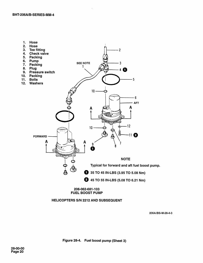
1. Hose2. Hose3. Tee fitting4. Check valve5. Packing6. Pump7. Packing8. Plug9. Pressure switch
10. Packing11. Bolts12. Washers
SEE NOTE1
NOTE
Typical for forward and aft fuel boost pump.
0 35 TO 45 IN-LBS (3.95 TO 5.08 Nm)
0 45 TO 55 IN-LBS (5.08 TO 6.21 Nm)
206-062-681-101FUEL BOOST PUMP
206A/BS-M-28-4-1
Figure 28-4. Fuel boost pump (Sheet 1 of 5)
28-00-00Page 18

C')
CO
Y
BHT 206A/B-SERIES-MM-4
NOTE: NO DRAIN PLUG REQD IN SEAL PUMP DRAIN ELECTRICAL
DISCHARGE PORT
AN4-5A BOLT (8 REQD) A AND PRESSUREAN960PD416L WASHER (8 REQD) / e SWITCH
SWITCH(IN DISCHARGE PORT)MS29512-10 PACKING
AN814-4DL PLUG(IN PUMP DRAIN PORT)
RG 12650 FUEL PORT ANDLOCKWIRE REQUIREMENTS (TYPICAL)
VIEW A-A
AN4-5A BOLT (8 REQD)AN960PD416L WASHER (8 REQD)
CCAI n9ZAI1U Pf)AT
LOCKWIRE
DISCHARGE PORTAND PRESSURESWITCH
AN4H5A BOLT (REF)
206-062-673-001 FUEL PUMP ANDLOCKWIRE REQUIREMENTS (TYPICAL)
DISCHARGE PORT ANDPRESSURE SWITCH
AN814-4DL PLUG(IN PUMP DRAIN PORT) iJMS29512-04 PACKING ELECTRICAL WIRING
206-062-673-003 FUEL PUMP ANDLOCKWIRE REQUIREMENTS
206-062-673-001 FUEL PUMP ANDLOCKWIRE REQUIREMENTS (TYPICAL)
VIEW A-A
HELICOPTERS S/N 4 THROUGH 660, AND 672 THROUGH 715
206A/BS-M-28-4-2
Figure 28-4. Fuel boost pump (Sheet 2)
28-00-00Page 19
z z
BHT 206A/B-SERIES-MM-4
1. Hose2. Hose3. Tee fitting4. Check valve5. Packing6. Pump7. Packing8. Plug9. Pressure switch
10. Packing11. Bolts12. Washers
SEE NOTE1
NOTE
Typical for forward and aft fuel boost pump.
Q 35 TO 45 IN-LBS (3.95 TO 5.08 Nm)
© 45 TO 55 IN-LBS (5.08 TO 6.21 Nm)
206-062-681-103FUEL BOOST PUMP
HELICOPTERS S/N 2212 AND SUBSEQUENT
206A/BS-M-28-4-3
Figure 28-4. Fuel boost pump (Sheet 3)
28-00-00Page 20

BHT 206A/B-SERIES-MM-4
FORM WIREBUNDLE THISAREA, SECUREWITH MS3367-1-9STRAPS
AN814-4DL PLUGMS29512-04 PACKING
GROUND WIRE TERMINALSWHT-BLU (OMIT WASHERUNDER BOLTHEAD)
LOCKWIRE
206-075-301-003CLAMP (OMITWASHER UNDERBOLTHEAD)
VIEW A-AVIEW LOOKING UP AT AFT PUMP
GROUND WIRE TERMINALSWHT-BLU (OMIT WASHERUNDER BOLTHEAD)
FORM WIREBUNDLE THISAREA.SECUREWITH MS3367-1-9STRAPS
AN814-4DL PLUGMS29512-04 PACKINGLOCKWIRE
VALVE LOCKING BAR
AN41-15A BOLT (8 READ)AN960PD416L WASHER(6 READ)
PUMP WIRESWHT-RED (+)WHT-BLU (-)
206-075-301-003CLAMP (OMITWASHER UNDER BOLTHEAD)
AN41-15A BOLT (8 READ)AN960PD416L WASHER(6 READ)
VIEW A-AVIEW LOOKING UP AT FORWARD PUMP
FWD
206-062-681-101
HELICOPTERS S/N 2212 AND SUBSEQUENT
206A/BS-M-28-4-4
Figure 28-4. Fuel boost pump (Sheet 4)
28-00-00Page 21

v31
CM
G)
Haw
s
BHT 206A/B-SERIES-MM-4
206-075-301-003CLAMP (OMITWASHER UNDERBOLTHEAD)
PUMP WIRESWHT-RED (+)WHT-BLU (-)
FORM WIREBUNDLE THISAREA.SECUREWITH MS3367-1-9STRAPS
206-075-301-003CLAMP (OMITWASHER UNDERBOLTHEAD)
PUMP WIRESWHT-RED (+)WHT- BLU (-)
FORM WIREBUNDLE THISAREA,SECUREWITH MS3367-1-9STRAPS
GROUND WIRE TERMINALSWHT-BLU (OMIT WASHERUNDER BOLTHEAD)
SWITCH WIRES
AN814-4DL PLUGVIEW A-A MS29512-04 PACKING
VIEW LOOKING UP AT AFT PUMP LOCKWIRE
AN814-4DL PLUGMS29512-04 PACKINGLOCKWIRE
AN4H5A BOLT (8 REQD)AN960PD416L WASHER
VIEW A-A (6 REQD)VIEW LOOKING UP AT FORWARD PUMP
FW
206-062-681-103
HELICOPTERS S/N 2212 AND SUBSEQUENT
206A/BS-M-28-4-5
Figure 28-4. Fuel boost pump (Sheet 5)
GROUND WIRE TERMINALSWHT-BLU (OMIT WASHERUNDER BOLTHEAD)
28-00-00Page 22

CL
=
E
C'-
013
°'d
B HT-206A/B-SERIES-M M-4
0.37 IN. (9.39 mm) 11 (6.10 mm)HOLE
LEAR SIEGLER INC.MODIFICATION PART NO. RG12650DPART NO. RG 12650
INLET SCREEN
0.37 IN. (9.39 mm)HOLE CENTER AREA
STELLAR HYDRAULICS CO.PART NO. 2861
rt1 0.40 IN.
16 mm)SEE DETAIL A
DETAIL A
OUTLET PORT
GLOBE INDUSTRIES DIVPART NO. 164A136MODIFICATION PART NO. 164A176COMPLIANCE WITH DETAIL ACHANGE TO PART NO. 164A204.
NO. 60 DRILLHOLE 0.040 IN.(1.02 mm)
206A/BS-M-28-5
Figure 28-5. Modification of fuel boost pumps
MODIFICATION PROCEDURE
1. Remove both front and rear fuel pumps, orprior to installation of a replacement fuelpump accomplish the following:
a. Inspect inlet screen(s) in each fuel pumpfor presence of two 0.37 inch (9.39 mm)holes. If holes are not present, invert pumpso screen(s) are down and drill two 0.37 inch(9.39 mm) holes. Holes are to be located asillustrated according to part number of fuelpump. Ensure all drill filings are removed.
b. On Globe Industries 164A136 or164A176 fuel pumps locate and drill (No. 60drill) hole in the outlet port as illustrated indetail A. Invert pump for drilling operationand ensure all drill filings have beenremoved.
c. Identify fuel pumps as indicated.
28-00-00Page 23

R-3
;:w
3
(OD
(7)
_030
A
°v=
.2)
viii
3'-(f)
0.0)
BHT 206A/B-SERIES-MM-4
5. Position new packing (5) on aft fuel pump (6) andinstall in fuel cell opening. Connect tee fitting (3), fuelsupply hose (2), and interconnect hose (1) to pump.Secure pump with eight washers (12) and bolts (11) O.
NOTE
Boltheads and external flange of fuel pumpsshould be clean to provide a good electricalbond. Omit one washer and install pumpground wire.
6. Position new packing (10) on forward pump (6) andinstall in fuel cell opening. Connect interconnect hose(1) to check valve (4) on forward pump. Secure pumpwith eight washers (12) O and bolts (11). Observepreceding note.
7. Install plug (8) and pressure switch (9) in Globe andLear Siegler fuel pumps as follows:
a. Globe boost pumps. Pumps contain one externalfuel drain port in mounting flange. Plug external fueldrain port with a new packing (7) and plug (8).
NOTE
No plug is required in Lear Siegler fuelpumps at seal drain port.
b. Lear Siegler boost pump. Pumps contain twoexternal ports in the mounting flange. Plug the fuel drainport with a new packing (7) and plug (8).
8. Install plug (8) and pressure switch (9) in pumps (6)as follows:
a. The pumps contain two external ports in themounting flange. When installing pump, plug the fueldrain port with a new packing (7) and plug (8).
b. Install pressure switch (9) O with a new packing
14. Secure plug (8) and pressure switch (9) usinglockwire. Secure drilled head bolts (11) in pumpmounting flange using lockwire. Refer to bottom view ofapplicable pump in figure 28-4.
15. Check pumps minimum pressure as follows:
a. Move helicopter to adequate tiedown facilitiesand secure for ground run.
b. Operate helicopter at flat pitch and 100 percentrotor speed with generator ON, refer to applicableJetRanger Flight Manual.
c. Check each individual pump with otherinoperative. Pump pressure should be 4 psig (27.58kPa) minimum and caution light segment should beilluminated for inoperative pump.
NOTE
Fuel pressure with both pumps in operationis not significant if each pump by itself meetsrequirements in step c. above.
d. Close both FUEL BOOST circuit breakers.Caution light segment should not be illuminated.
28-21. FUEL PUMP CARTRIDGE.
SPECIAL TOOLS REQUIRED
Number Nomenclature
E2-10-1 Cartridge Removal
28-22. REPLACEMENT - FUEL PUMPCARTRIDGE IN 206-062-673-001 PUMP.
(10). 1.
9. Connect electrical wiring to forward and aft pumps 2.(6).
3.10. Inspect installation for security.
11. Connect battery and close fuel shutoff valve.
12. Perform leak test on fuel cell (paragraph 28-13,step 18).
13. Bleed trapped air from both pumps (6) afterrefueling by removing drain plug and draining a smallamount of fuel from cell.
Disconnect battery and/or external power supply.
Drain fuel from cell (Chapter 12).
Disconnect electrical wiring at applicable fuel pump(6, figure 28-4).
4. Remove drain plug (8) and packing (7).
5. Remove retaining ring.
6. Install E2-10-1 special cartridge removal tool inpump drain boss and remove motor/impeller cartridge.
7. Clean cartridge hole and retaining ring.
28-00-00Page 24

(o)
-lo
too
=C
D
0(n.
0
0
ZOO
u000
Off
(
CS
C
E
(/)
111
0UQ
O
°C)
(()
E
E(/)
.-.
,-.
+-O
E.L.-
BHT 206A/B-SERIES-MM-4
8. Lubricate packings furnished on replacementmotor/impeller cartridge and sides of the cartridge holein mounting flange casting with approved fuel.
28-23. REPLACEMENT - FUEL PUMPCARTRIDGE IN 206-062-681-101 CANISTER TYPEFUEL BOOST PUMP.
CAI/TION
DO NOT FORCE ECCENTRICCARTRIDGE. DESIGN REQUIRESALIGNMENT ARROWS TO BE WITHIN 3DEGREES TO BE PROPERLY INSTALLED.
NOTE
Align arrows on motor/impeller cartridge andon mounting flange.
9. Install motor/impeller cartridge in flange with arrowsaligned and ensure it is properly seated and retainingring groove is not obstructed.
10. Install retaining ring.
11. Install drain plug (8) with packing (7). Secure bolts(11) using lockwire as shown in view A-A for206-062-673-001 fuel pump.
DO NOT OVERTIGHTEN POSITIVE (+)LEAD TERMINAL.
12. Connect electrical leads to the motor/impellercartridge (Chapter 98).
13. Perform fuel boost pump operational check.
a. Ensure both boost pumps are covered with fuel.Refuel helicopter as required (Chapter 12).
b. Connect battery and/or external power supply.
c. Turn battery switch on and close fuel boost pumpcircuit breaker. Check fuel gage for adequate pressurefrom that pump with other pump inoperative (paragraph28-20, step 15).
d. Turn battery switch off. Check exterior of boostpumps for evidence of leakage.
1. Prepare helicopter by disconnecting battery and/orexternal power supply.
2. Remove socket head screw from valve locking bar(figure 28-4). Rotate bar clear of cartridge.
NOTE
Removal of socket head screw will
disconnect electrical negative (-) lead andwill allow valve locking bar to extend, closingoff fuel supply to cartridge.
3. Disconnect positive (+) electrical lead from cartridgeterminal and move wiring clear of cartridge area.
4. Remove drain plug, (8, figure 28-4), from cartridgecenter boss and allow trapped fuel to drain. Remove anddiscard packing.
5. Remove retaining ring securing cartridge in pumphousing.
6. Install E2-10-1 special cartridge removal tool inpump drain plug boss and secure with check nut. Usingweight, impact cartridge from pump housing. Removetool from cartridge.
7. Clean all foreign matter from cartridge bore andretaining ring groove in pump housing and fromretaining ring.
8. Lubricate V747-75-2-033 and V747-75-2-034packings, (furnished with new cartridge) with approvedfuel.
9. Using hand pressure, install cartridge in pumphousing with arrows aligned on flanges (within ±3degrees). E2-10-1 special cartridge removal tool maybe used as a work aid during installation. Do not impactcartridge as damage to parts may result.
10. Secure cartridge in pump housing with retaining ring.
11. Install drain plug (8) in cartridge boss with newpacking (7). Double safety plug to adjacent mountingbolts with lockwire.
NOTE
Refer to Chapter 98 for wiring diagram.
12. Rotate valve locking bar over cartridge and in linewith negative (-) terminal. Insert WHT-BLU negative (-)lead terminal under bar and secure both with screw.
28-00-00Page 25
=.W
.W.
((D
D0)
W
Zip
(DO
3;7 0-0
SU
ET
}'O
CO
)
0)C-
0
BHT 206A/B-SERIES-MM-4
13. Connect WHT-RED positive (+) lead terminal topositive (+) terminal on cartridge; do not overtighten.
14. Perform fuel boost pump operational check.
a. Ensure both boost pumps are covered with fuel.Refuel helicopter as required (Chapter 12).
b. Connect battery and/or external power supply.
c. Set battery switch to ON and close fuel boostpump circuit breaker. Check fuel gage for adequatepressure from each pump with other pump inoperative(paragraph 28-20, step 15).
d. Set battery switch to OFF. Check exterior ofboost pumps for evidence of leakage.
28-24. REPLACEMENT - FUEL PUMP CARTRIDGEIN 206-062-681-103 CANISTER TYPE FUEL BOOSTPUMP.
1. Prepare helicopter by disconnecting battery and/orexternal power supply.
2. Disconnect positive (+) and negative (-) leads fromcartridge and move wiring clear of cartridge area (figure28-4).
3. Remove lockwire, three bolts and washers (one athandle, two approximately 180 degrees opposite)securing cartridge in pump housing.
4. Pull cartridge handle and remove cartridge frompump housing. The handle contains a cam lever footthat provides a mechanical advantage to reduce frictionforce of packings when removing cartridge.
5. Remove drain plug (8) from cartridge center bossand discard packing. Install plug replacement cartridgewith a new packing (7).
6. Clean all foreign matter from cartridge bore in pumphousing.
7. Lubricate packings, MS29513-136 andMS29513-033 (furnished with new cartridge) withapproved fuel.
8. Install cartridge in pump housing with the two boltholes in cartridge flange and housing aligned. Fully seatcartridge in housing with handle closed. Securecartridge in housing with three bolts and washers.Safety boltheads with lockwire (figure 28-4).
9. Secure drain plug to an adjacent bolthead withlockwire.
10. Connect positive (+) and negative (-) leads toterminals on cartridge. Do not overtighten.
11. Perform fuel boost pump operational check.
a. Ensure both boost pumps are covered with fuel.Refuel helicopter as required (Chapter 12).
b. Connect battery and/or external power supply.
c. Set battery switch on ON and close fuel boostpump circuit breaker. Check fuel gage for adequatepressure from each pump with other pump inoperative(paragraph 28-20, step 15).
d. Set battery switch to OFF. Check exterior ofboost pumps for evidence of leakage.
28-25. FUEL SHUTOFF VALVE.
A motor operated shutoff valve incorporating a thermalrelief feature is installed in main fuel supply line and islocated in fuel compartment above fuel filler cap. Valveis electrically controlled by an ON-OFF switch locatedon instrument panel and protected by a circuit breakerlocated in overhead console panel. In event of electricalfailure valve will remain in position selected beforefailure.
28-26. REMOVAL (Helicopters S/N 4 through 153).
1. Pull circuit breaker, remove coverplate above fillercap, and disconnect electrical connector on fuel shutfoffvalve.
2. Disconnect tube (9, figure 28-6).
3. Disconnect pressure indicating tube (1) from cross(2) and remove bolts (3) washers (4) and nuts (5),securing fuel shutoff valve (6) to bracket (8).
28-27. INSTALLATION (Helicopters S/N 4 through153).
1. Position cross (2), fuel shutoff valve (6), andconnector (7) on bracket (8), and install bolts (3),washers (4), and nuts (5).
2. Connect tube assemblies (1 and 9) and electricalconnector.
3. Install coverplate, and close circuit breaker.
28-00-00Page 26

BHT 206A/B-SERIES-MM-4
13
14
HELICOPTERS S/N 4 THROUGH 153
HELICOPTERS S/N 154 THROUGH 3566
206A/BS-M-28-6-1
Figure 28-6. Fuel shutoff valve (Sheet 1 of 2)
28-00-00Page 27

N--
B HT-206A/B-SERIES-M M-4
HELICOPTERS S/N 3567 AND SUBSEQUENT
1. Tube 13. Washer2. Cross 14. Nut3. Bolt 15. Valve assembly4. Washer 16. Bracket5. Nut 17. Tube6. Fuel shutoff valve 18. Cross7. Connector 19. Connector8. Bracket 20. Fuel shutoff valve9. Tube 21. Tube
10. Tube 22. Tube11. Bolt 23. Screw12. Washer 24. Washer
206A/BS-M-28-6-2
Figure 28-6. Fuel shutoff valve (Sheet 2)
28-00-00Page 28

0l<
v0)
c
-60.
03=
W
.-:
0
c°)
0E
0
ate-
(t)
0
0
28-28. REMOVAL (Helicopters S/N 154 through3566).
1. Pull circuit breaker, remove coverplate above thefiller cap, and disconnect electrical connector on fuelshutoff valve (15).
2. Provide suitable container to catch fuel and disconnecttube (10, figure 28-6), and fuel supply tube (17).
3. Remove bolts (11) washers (12 and 13) and nuts(14), securing fuel shutoff valve assembly (15) to mountbracket (16).
28-29. INSTALLATION (Helicopters SIN 154through 3566).
1. Position cross (18, figure 28-6) fuel shutoff valveassembly (15) and connector (19) on mount bracket(16), and install bolts (11), washers (12 and 13) and nuts(14).
2. Connect tube (10), fuel supply line (17), andelectrical connector.
3. Install coverplate and close circuit breaker.
28-30. REMOVAL (Helicopters S/N 3567 andsubsequent).
1. Remove right side fuel compartment access panel.
2. Disconnect electrical connector from fuel shutoffvalve (20, figure 28-6).
3. Disconnect tubes (21 and 22) from fuel shutoff valve.
4. Remove screws (23) with washers (24). Removefuel shutoff valve (20).
28-31. INSPECTION.
1. Inspect fuel shutoff valve for leaks.
2. Inspect fuel lines and electrical connectors forsecurity.
28-32. INSTALLATION (Helicopters S/N 3567 andsubsequent).
1. Position fuel shutoff valve (20, figure 28-6) in placeand install washers (24) and screws (23).
B HT-206A/B-SERIES-M M-4
2. Connect tubes (21 and 22) to fuel shutoff valve.
3. Connect electrical connector to fuel shutoff valve.
4. Install right side fuel compartment access door.
28-33. FUEL PRESSURE TRANSDUCER.
The fuel pressure transducer provides a means ofmonitoring fuel pressure. The transducer is located ona fitting on top of aft right side of fuel cell.
28-34. REMOVAL.
1. Remove fuselage access panel located above fuelfilter.
2. Disconnect electrical connector (4, figure 28-7).
3. Unscrew fuel pressure transducer (3) from fitting(1). Remove and discard packing (2).
28-35. INSPECTION.
1. Inspect transducer for rust or corrosion.
2. Inspect for bent or broken pins.
28-36. INSTALLATION.
1. Install new packing (2, figure 28-7) on transducerand screw into fitting (1).
2. Connect electrical connector (4).
3. Pressurize fuel system and check for leaks(paragraph 28-6, and Chapter 5).
4. Install fuselage access panel.
28-37. FUEL QUANTITY - INDICATINGUNITS.
Two float type fuel level transmitting units (tank units)are installed in fuel cell. The lower unit is mounted in thetank bottom and monitors fuel level up to horizontalsurface of cell, under seat; upper unit monitors fuel levelin upper section of fuel cell, behind seat, and is mountedto top of fuel cell. Both indicating units are connected toa common quantity indicator. Refer to Chapter 95 forcalibration procedures and troubleshooting.
28-00-00Page 29

(OD
.-«
CA
D
CD
'-' (ten
0
0.Z3
Op)
B HT-206A/B-SERIES-MM-4
DETAIL A
1. Fitting2. Packing3. Fuel pressure transducer4. Electrical connector
206A/BS-M-28-7
28-38. REMOVAL.
Figure 28-7. Fuel pressure transducer
1. Disconnect battery and defuel helicopter (Chapter12).
2. Disconnect electrical wiring to upper or lower tankunit (1 or 2, figure 28-8).
2. Remove protective covers from fuel cell openingsfor upper and lower tank unit (1 and 2).
3. Insert upper or lower tank units (1 or 2) into fuel cellopening and secure with three screws (3 or 4) andwashers (5 or 6).
NOTE
3. Remove three screws (3 or 4) and washers (5 or 6)from upper and lower tank units (1 and 2) and removefrom fuel cell. Discard gasket.
4. Cover fuel cell opening to prevent entrance offoreign material.
5. Remove five screws (7) and washers (8) from tank unitdoubler (9 or 10) and separate doubler from tank unit.
28-39. INSTALLATION.
1. Position new gasket (11) on inside flange of upperor lower tank unit (1 or 2, figure 28-8). Install doubler (9or 10) and secure with five screws (7) and washers (8).
Position float arm of upper tank unit to theright side of helicopter and lower tank unitfloat arm forward.
4. Connect electrical wiring to upper and lower tankunits (1 or 2).
5. Inspect fuel cell installation for security.
6. Connect battery and close fuel shutoff valve.
7. Perform leak test on fuel cell (paragraph 28-13, step16).
8. Refer to Chapter 95 for fuel quantity calibration.
28-00-00Page 30

BHT 206A/B-SERIES-MM-4
1. Upper tank unit 7. Screw2. Lower tank unit 8. Washer3. Screw 9. Doubler4. Screw 10. Doubler5. Washer 11. Gasket6. Washer
206A/BS-M-28-8
Figure 28-8. Fuel quantity indicator units
28-00-00Page 31
)ON
C_'
,
(DD
AO
)
(OD
c)'1
am:
L(7
Qom
)
BHT-206A/B-SERIES-MM-4
28-40. DRAIN VALVE.
Drain valve is a manually operated valve located inbottom of fuel cell and is used to drain fuel.
28-41. REMOVAL.
1. Ground helicopter. Disconnect battery and externalpower source.
2. Defuel and purge fuel cell (Chapter 12).
3. Remove screws (1, figure 28-9), washers (2), andbolts (3).
4. Remove drain valve (7) with fitting (5) and packings(4 and 6); discard packings.
28-42. INSTALLATION.
1. Lubricate new packings (4 and 6, figure 28-9) withapproved fuel before installation.
2. Place new packing (6) on drain valve (7).
3. Place new packing (4) on fitting (5).
4. Install drain valve (7) with fitting (5).
5. Secure drain valve (7) in closed position usinglockwire.
28-43. SOLENOID VALVE.
The solenoid valve is an electrically and manuallycontrolled drain valve used to drain fuel from fuel cell.
28-44. REMOVAL.
1. Ground helicopter. Disconnect battery and externalpower source.
2. Defuel and purge fuel cell (Chapter 12).
3. Remove screw (1, figure 28-10), and washer (2).
4. Remove solenoid valve (4) with packing (3).
28-45. INSTALLATION.
1. Lubricate new packing (3) with approved fuel beforeinstallation.
2. Place new packing (3, figure 28-10) on solenoidvalve (3).
3. Install solenoid valve (4) with screw (1) and washers (2).
4. Tighten screws (1) 0.
5. Secure solenoid valve (4) using lockwire.
28-46. CAP.
Cap and adapter assembly covers fuel access openingat top of fuel cell.
28-47. REMOVAL.
1. Ground helicopter and disconnect battery.
2. On helicopters S/N 4 through 3566, remove screws(1, figure 28-11), washers (2), retainer (3), cap andadapter (4), with packings (6, 7, and 8), and seal (5).Discard seal (5) and packings.
3. On helicopters S/N 3567 and subsequent, removescrews (1), washers (2) retainer (3), hinged cap andadapter (9), seal (5), and packing (6).
28-48. INSTALLATION.
1. Lubricate new packings (6, 7, and 8, figure 28-11)with approved fuel before installation.
2. On helicopters S/N 4 through 3566 place newpacking (6) in fuel cell port.
3. Install new packing (7 and 8) on cap and adapter (4).
4. Position seal (5), cap and adapter (4), and retainer(3) in place and secure with washers (2) and screws (1)05. On helicopters S/N 3567 and subsequent, placenew packing (6) in fuel cell port.
6. Prepare hinged cap and adapter assembly andretainer assembly for installation. Using Scotchbrite or400 grit paper, remove alodine protective finish locallyfrom inboard side of retainer to ensure good electricalbond.
7. Install seal (5), hinged cap and adapter (9), retainer(3), and secure with washers (2), and screws (1) 0 .
8. Connect battery and remove ground.
28-00-00Page 32

cam.)
BHT 206A/B-SERIES-MM-4
1. Screw2. Washer3. Bolt4. Packing5. Fitting6. Packing7. Drain valve
1
206A/BS-M-28-9
Figure 28-9. Drain valve
1. Screw2. Washer3. Packing4. Solenoid valve
25 TO 35 IN-LBS 0 1
(2.83 TO 3.96 Nm)
206A/BS-M-28-10
Figure 28-10. Solenoid valve
28-00-00Page 33

GO
DN
-+
BHT-206A/B-SERIES-MM-4
"12 O'CLOCK HOLE"
SEE VIEW A
1. Screws2. Washer3. Retainer4. Cap and adapter5. Seal6. Packing7. Packing8. Packing9. Hinged cap and adapter
VIEW A
NOTES
A Helicopters S/N 4 through 3566.
A Helicopters S/N 3567 and subsequent.
© 50 TO 75 IN-LBS (5.65 TO 8.48 Nm).
206ABS-M-28-11
Figure 28-11. Cap and adapter assembly
28-00-00Page 34

Al' B
CD
m
"1I
-_-C
D
o;7
-*.
-T`
CC
)
LC
D
>'c
c/)
E
LC
)
CC)
BHT-206A/B-SERIES-MM-4
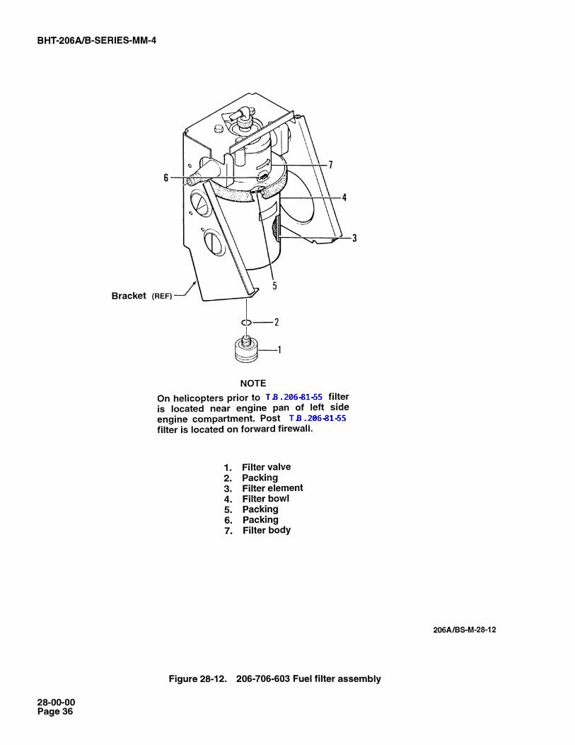
28-49. FILTER ELEMENT CHANGEREQUIREMENT.
4. Install bowl (4) on filter body (8) and tighten untilpacking (7) contacts filter body. Draw a vertical line onfilter bowl and body.
Airframe mounted fuel filter element shall change atsame hourly interval as engine fuel filter (located in fuelpump housing) and after any indication of clogging notdue to removable ice particles.
28-50. REMOVAL AND INSTALLATION206-706-603 FILTER ELEMENT.
1. Remove lockwire securing filter bowl (4, figure28-12) to filter valve (1).
2. Remove filter bowl (4) and filter element (3). Discardused filter element, and packing (2, 5, and 6).
3. Install new filter element (3), packings (2, 5, and 6)and filter bowl (4).
4. Install filter bowl (4) on filter body (7) and tightenuntil packing (5) contacts filter body. Mark a vertical lineon filter bowl and body.
5. Tighten bowl 60 to 90 degrees past mark.
NOTE
Turning bowl 60 degrees past the referencemark will normally prevent any leakage. Ifleakage occurs at this point, continuetightening to a maximum of 90 degrees (90degrees represents 150 inch-pounds (16.95Nm).
6. Install lockwire to secure filter bowl (4) to filter valve(1).
7. Bleed air from fuel system. Refer to Chapter 5Special Inspections.
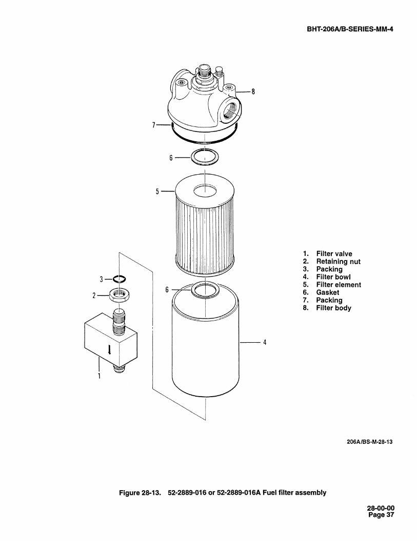
28-51. REMOVAL AND INSTALLATION -52-2889-016 OR 52-2889-016A FILTER ELEMENT.
1. Remove lockwire securing filter bowl (4, figure28-13) to filter valve (1).
2. Using a strap wrench, remove the filter bowl (4) andfilter element (5). Discard used filter element, gaskets(6), and packing (7 and 3).
3. Install filter element (5), gaskets (6), and packing (7)in filter bowl (4).
5. Accomplish steps 5. through 7. of paragraphs 28-50.
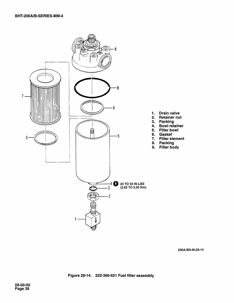
28-52. REMOVAL AND INSTALLATION -222-366-621-101 FILTER ELEMENT.
1. Remove lockwire securing bowl retainer (4, figure28-14) and drain valve (1).
2. Drain fuel from filter bowl (5) and remove drain valve(1), retainer nut (2), and packing (3) from filter bowl.
3. Remove filter bowl (5), packing (8), filter element(7), and gaskets (6). Discard packings, filter element,and gaskets.
4. Install filter element (7), and gaskets (6) in filter bowl(5). Ensure that gaskets are installed with concave sidefacing the filter element.
5. Lubricate all packings with approved fuel, andinstall packing (8) in filter body (9).
6. Install filter bowl (5) with filter element (7) andgaskets (6) in filter body and tighten retainer bowl (4)
0.7. Install packing (3), retainer nut (2), and drain valve(1). Secure drain valve to retainer nut with lockwire.
8. Bleed air from fuel system. Refer to Chapter 5Special Inspection.
28-53. AIRFRAME MOUNTED FUEL FILTER.
A fuel filter is mounted to structure on left side of enginecompartment (right side of forward firewall onhelicopters S/N 3387 and subsequent). Fuel filter (figure28-15) consists of a replaceable filter element, drainvalve, bypass valve, impending bypass switch, andmanual test button. The airframe mounted fuel filterassembly eliminates requirement for adding anti-icingadditive to fuel supply when temperatures are below40°F (4°C). Indication of impending bypass lights theA/F FUEL FILTER segment on pilot caution panel.
NOTE
Filter element must be replaced when cautionlight comes on during engine operation. Replacefilter element at same hourly interval as enginefuel filter maintenance is performed or 300hours. (Refer to Allison 250-C20 SeriesOperation and Maintenance Manual, 10W2.)
28-00-00Page 35
fl.
((D
D
(TI
0a.+
_O+
L(.
B HT-206A/B-SERIES-M M-4
NOTE
On helicopters prior to T.B. 206-81-55 filteris located near engine pan of left sideengine compartment. Post T.B. 206-81-55filter is located on forward firewall.
1. Filter valve2. Packing3. Filter element4. Filter bowl5. Packing6. Packing7. Filter body
206A/BS-M-28-12
Figure 28-12. 206-706-603 Fuel filter assembly
28-00-00Page 36
BHT 206A/B-SERIES-MM-4
8
1. Filter valve2. Retaining nut3. Packing4. Filter bowl5. Filter element6. Gasket7. Packing8. Filter body
4
206A/BS-M-28-13
Figure 28-13. 52-2889-016 or 52-2889-016A Fuel filter assembly
28-00-00Page 37
N-+
,.N
BHT 206A/B-SERIES-MM-4
1. Drain valve2. Retainer nut3. Packing4. Bowl retainer5. Filter bowl6. Gasket7. Filter element8. Packing9. Filter body
25 TO 50 IN-LBS(2.83 TO 5.65 Nm)
206A/BS-M-28-14
Figure 28-14. 222-366-621 Fuel filter assembly
28-00-00Page 38

mom
B HT-206A/B-SERIES-M M-4
INLET
SWITCHING ASSEMBLY
OUTLET BLEED PORT A0.026 IN. (aSEE NOTE
OUTLETSEE VIEW A
3
SECTION THRU FILTER
OUTLET BLEEDPORT 0.026 IN.(0.66 mm)DIAMETER-
Helicopters S/N 2212 through 3386
Figure 28-15. Airframe mounted fuel filter assembly (Sheet 1 of 2)
206ABS-M-28-15-1
28-00-00Page 39

CIO
",-
BHT-206A/B-SERIES-MM-4
INLET OUTLET
SEE VIEW A
_ iOUTLET BLEED
1NPORT 0.026 ./A /(0.66 mm) DIA V L 0.06 IN. (1.52 mm)
OUTLET BLEED PORT0.026 IN. (0.66 mm) DIA
LSEE NOTE
30°/40°
VIEW A
SECTION THRU FILTER
1. Filter element 7. Packing2. Filter bowl retainer 8. Packing3. Drain valve 9. Packing4. Filter bowl 10. Gasket5. Filter head 11. Gasket6. Packing
NOTES
1Q To ensure self-bleeding of fuel filter,check outlet bleed port with 0.020 inch(0.51 mm) wire.
Q2 On helicopters prior to T.B. 206-81-55filter is located near engine pan on leftside engine compartment. Post T.B.206-81-55 filter is located on forwardfirewall.
14- -
RIGHT SIDE FORWARD FIREWALL© 25 TO 50 IN-LBS (2.83 TO 5.65 Nm)
HELICOPTERS S/N 3387 AND SUBSEQUENT206A/BS-M-28-15-2
Figure 28-15. Airframe mounted fuel filter assembly (Sheet 2)
28-00-00Page 40

BHT-206A/B-SERIES-MM-4
28-00-00
ECCN EAR99
NOTE
Refer to Service Instruction No. 206-65 fordetailed installation instructions and wiringdiagrams.
Purge fuel system after any filter maintenance(Chapter 12).
28-54. AIRFRAME MOUNTED FUEL FILTER —REMOVAL
1. Remove filter element (1, Figure 28-15) asfollows:
a. Cut and remove lockwire securing filter bowlretainer (2) and drain valve (3).
b. Remove drain valve (3) and drain fuel fromfilter bowl (4).
c. Remove filter bowl retainer (2) and filter bowl(4) from filter head (5).
d. Remove filter element (1) from filter bowlretainer (2). Discard packings (6, 7, 8, and 9).
28-55. AIRFRAME MOUNTED FUEL FILTER —INSPECTION
1. Remove contamination and residual water fromfilter bowl (4, Figure 28-15).
2. Examine filter element (1) for evidence ofcontamination. Ice crystals and water found present inthe filter element may be removed. No othercontaminant is removable.
3. At each fuel filter element (1) change interval,remove fitting from outlet port of filter head (5). Using a0.020-inch (0.51-mm) wire, pass wire through outletbleed port to ensure that bleed port is not clogged.
4. Reinstall fitting to outlet port of filter head (5).Torque 235 to 265 inch-pounds (27 to 30 Nm).
NOTE
Use new filter element replacement kitKD651511 (FMC 05160) if element iscontaminated or due for time replacement.
5. Refer to applicable JetRanger Flight Manual fordaily inspection requirement.
28-56. AIRFRAME MOUNTED FUEL FILTER —INSTALLATION
1. Lubricate all packings with approved fuel.
2. Install new packings (7, 8, and 9, Figure 28-15).
3. Install new packing (6) in filter head (5).
4. Install filter bowl (4) with filter element (1), andgaskets (10 and 11) into filter head (5). Tighten filterbowl retainer (2) .
5. Install drain valve (3) and secure with filterretainer bowl (2) to filter bowl (4) tab using lockwire.
6. Bleed air from fuel system.
NOTE
When purging airframe and engine fuelsystem of air, ensure both fuel boost pumpsare on and motor engine for approximately15 seconds or until no evidence of air iscoming from the fuel supply hose. Inaddition, depress airframe fuel filter bypassindicator button during motoring operationto remove air more rapidly.
Refer to Rolls-Royce 250-C20 SeriesOperation and Maintenance Manual, 10W2for engine fuel system maintenancerequirements.
7. Run engine and check for fuel leaks.
28-57. ENGINE FUEL FILTER
Refer to Rolls-Royce 250-C20 Series Operation andMaintenance Manual, 10W2 for detailed maintenanceinstructions.
T
13 OCT 2011 Rev. 11 Page 41/42
