bfm136 branch feeder monitor - satec global · 2 bfm136 branch feeder monitor limited warranty the...
TRANSCRIPT

BFM136 Branch Feeder Monitor
Installation and Operation Manual
BG0394 Rev. A10

2 BFM136 Branch Feeder Monitor
LIMITED WARRANTY
The manufacturer offers the customer a 24-month functional warranty on the instrument for faulty workmanship or parts from date of dispatch from the distributor. In all cases, this warranty is valid for 36 months from the date of production. This warranty is on a return to factory basis.
This warranty is only applicable to SATEC instruments using HACS SATEC current transformers.
The manufacturer does not accept liability for any damage caused by instrument malfunction. The manufacturer accepts no responsibility for the suitability of the instrument to the application for which it was purchased.
Failure to install, set up or operate the instrument according to the instructions herein will void the warranty.
Only a duly authorized representative of the manufacturer may open your instrument. The unit should only be opened in a fully anti-static environment. Failure to do so may damage the electronic components and will void the warranty.
The greatest care has been taken to manufacture and calibrate your instrument. However, these instructions do not cover all possible contingencies that may arise during installation, operation or maintenance, and all details and variations of this equipment are not covered by these instructions.
For additional information regarding installation, operation or maintenance of this instrument, contact the manufacturer or your local representative or distributor.
WARNING
Read the instructions in this manual before performing installation and take note of the following precautions:
BFM136 is intended for measurements performed in building installations, relating to measurement category III (UL61010-1, 6.7.4).
Ensure that all incoming AC power and other power sources are turned OFF before performing any work on the instrument. Failure to do so may result in serious or even fatal injury and/or equipment damage.
Before connecting the instrument to the power source, check the labels at the front of the instrument to ensure that your instrument is equipped with the appropriate rating input voltages and currents.
Under no circumstances should the instrument be connected to a power source if it is damaged.
To prevent potential fire or shock hazard, do not expose the instrument to rain or moisture.
While installing HACS to the secondary of an external third party current transformer, the external current transformer secondary output must never be allowed to be open circuit when the primary is energized. An open circuit can cause high voltages, possibly resulting in equipment damage, fire and even serious or fatal injury. Ensure that the current transformer wiring is secured using an external strain relief to reduce mechanical strain on the screw terminals, if necessary.
Only qualified personnel familiar with the instrument and its associated electrical equipment must perform setup procedures.
Do not open the instrument under any circumstances when it is connected to a power source.
Do not use the instrument for primary protection functions where failure of the device can cause fire, injury or death. The instrument can only be used for secondary protection if needed.
Read this manual thoroughly before connecting the device to the current carrying circuits. During operation of the device, hazardous voltages are present on input terminals. Failure to observe precautions can result in serious or even fatal injury or damage to equipment.
All trademarks are property of their respective owners. March 2015
Copyright 2005-2015 SATEC Ltd.

BFM136 Branch Feeder Monitor 3
Table of Contents
Chapter 1 General Information ............................................................ 7
Labeling ............................................................................................................... 8
Chapter 2 Installation ........................................................................... 9
Mechanical Installation ........................................................................................ 9
Electrical Installation .......................................................................................... 12
Communications ................................................................................................ 16 RS-485 Connection ................................................................................................ 16 RS232 Connection ................................................................................................. 18 Modem Connection ................................................................................................ 18 Ethernet Connection .............................................................................................. 19 RF ........................................................................................................................ 19
Controls and Indicators ...................................................................................... 20 Indicator LEDs ....................................................................................................... 20 Energy Pulse LED ................................................................................................. 20 Front Panel Display ................................................................................................ 20
Device Settings .................................................................................................. 21 Password .............................................................................................................. 21 Submeter System .................................................................................................. 21 Submeter Addressing ............................................................................................. 21 Basic Device Settings ............................................................................................ 22 Energy/TOU System .............................................................................................. 22
Device Diagnostics ............................................................................................ 22
Chapter 3 BFM136 Display Operations ............................................. 23
Startup Diagnostics ............................................................................................ 23
Display Features ................................................................................................ 23 Submeter Displays ................................................................................................. 23 Display Update ...................................................................................................... 23 Auto Return ........................................................................................................... 23 Auto Scroll ............................................................................................................ 23 Backlight ............................................................................................................... 23
Navigation Buttons ............................................................................................. 23
Display Views .................................................................................................... 24
Navigating in Menus .......................................................................................... 28 Entering Numbers .................................................................................................. 28 Entering a Password .............................................................................................. 28 Selecting Menus .................................................................................................... 28 Viewing and Changing Setup Items ......................................................................... 29
Menu Operations ............................................................................................... 29 Submeter Channel Assignments ............................................................................. 29 Reset ................................................................................................................... 30 Real Time Clock Setting ......................................................................................... 31 Basic Device Settings ............................................................................................ 31 Transformer Correction .......................................................................................... 31 Device Options ...................................................................................................... 32 Communication Ports ............................................................................................. 32 Local Network Settings ........................................................................................... 33 Local Settings........................................................................................................ 33 Meter Security ....................................................................................................... 34 Display Settings ..................................................................................................... 34

4 BFM136 Branch Feeder Monitor
Chapter 4 PAS Application Software ................................................. 36
Setting up your Submeters ................................................................................ 36
Setting up Communications ............................................................................... 37 Communicating through a Serial Port ....................................................................... 37 Communicating through the Internet ........................................................................ 38
Preparing Setups ............................................................................................... 39 Downloading Setups .............................................................................................. 39 Uploading Setups .................................................................................................. 39
Authorization ...................................................................................................... 39
Changing Port Settings ...................................................................................... 40 Setting Up Communication Ports ............................................................................. 40 Setting Up the Local Network .................................................................................. 40 Configuring Wireless RF Connections ...................................................................... 41 Configuring eXpertPower Client .............................................................................. 41
General Meter Setup ......................................................................................... 43 Basic Meter Setup ................................................................................................. 43 Channel Assignments ............................................................................................ 44 Transformer Correction .......................................................................................... 45 Local Settings........................................................................................................ 46 Using Alarm/Control Setpoints ................................................................................ 47
Configuring Billing Energy and TOU Registers ................................................. 48 Setting up Total and Tariff Registers ........................................................................ 49 Configuring the Daily Tariff Schedule ....................................................................... 50 Configuring the Season Tariff Schedule ................................................................... 51
Configuring Data Recorders .............................................................................. 52
Remote Device Control ...................................................................................... 52 Viewing and Clearing Device Diagnostics ................................................................. 53 Updating the Clock ................................................................................................ 53 Clearing Maximum Demands and Log Files .............................................................. 53
Administration .................................................................................................... 54
Upgrading Device Firmware .............................................................................. 54
Data Monitoring ................................................................................................. 57 Viewing Real-Time Data ......................................................................................... 57 Retrieving Log Files ............................................................................................... 57
Appendix A Technical Specifications ................................................. 60
Appendix B HACS Connection Template .......................................... 63
Appendix C Parameters for Data Monitoring and Logging ................. 64
Appendix D Setpoint Triggers and Actions ........................................ 68
Appendix E Data Scales .................................................................... 69
Appendix F Device Diagnostic Codes ............................................... 70

BFM136 Branch Feeder Monitor 5
This package contains
BFM136
High Accuracy Current Sensors - HACS1 according to your request, for more options refer to HACS_Datasheet catalog
HACS - 100A – (solid core) Internal Hole 12 mm (0.47")
HACS - 100A – (solid core) Internal Hole 23 mm (0.91")
HACS - 400A – (solid core) Internal Hole 26 mm (1.02")
HACS - 100A – (solid core) Internal Hole 16 mm (0.63")
1 HACS – SATEC proprietary current sensor

6 BFM136 Branch Feeder Monitor
Designator Label Sets
10
11
12
13
14
15
16
17
18
19
20
21
22
23
24
25
26
27
28
29
30
31
32
33
34
35
36
1
2
3
4
5
6
7
8
9
3
12 1
6
25 4
9
38 7
12
41
1
10
15
51
4
13
18
61
7
16
21
72
0
19
24
82
3
22
27
92
6
25
30
10
29
28
33
11
32
31
36
12
35
34
HACS designator label set - to attach to the HACS
Cable designator tie-marker

Chapter 1 General Information
BFM136 Branch Feeder Monitor 7
Chapter 1 General Information
The BFM136 is a 3-phase, multi-channel, multi-function energy meter suitable for use in single-phase and multi-phase electrical networks.
Meter highlights
Multi-channel submetering – up to 36 single-phase or 18 two-phase or 12 three-phase submeters in a single device. Any combination of single-, two-, and three-phase consumers can be chosen up to a total of 36 current inputs.
Automatic totalization energy from different sub-consumers
Features
Calibrated to meet Class 0.5S active energy and Class 1 reactive energy meter accuracy
3-phase/2-phase/single-phase meters (true RMS, volts, amps, power, power factor, neutral current)
Ampere/Volt demand meter
Time-of-Use, 4 energy/demand registers x 6 tariffs1, 4 seasons x 4 types of days, 8 tariff changes per day, easy programmable tariff schedule
Import/export energy and power demands
Automatic 120–day daily profile for import/export2 energy and maximum demand readings (total and tariff registers) separate for each submeter
Event recorder for logging internal diagnostic events and setpoints operations
Data recorders; programmable periodical data logs separate for each submeter
Embedded programmable controller (4 control setpoints, programmable thresholds and delays) separate for each submeter
Easy to read 2-row x 16 characters LCD display with backlight (BFM136 only)
50/60 Hz operation
Internal clock, keeping the clock running over one week without external power
HACS with overvoltage protection diodes to avoid any damage while disconnecting the primary current sensor
Standard RS-485 serial port
Optional second communication port. Communication options available:
RS-232
RS-422/485
56K Dial-up modem
Ethernet 10/100BaseT
Wireless RF modem (unlicensed 907-922 MHz)
Modbus RTU and Modbus ASCII communication protocols
Easy field upgrading device firmware through any communication port
1 From Firmware version 18.4.1 2 From Firmware version 18.5.1
Chapter 1 General Information
8 BFM136 Branch Feeder Monitor
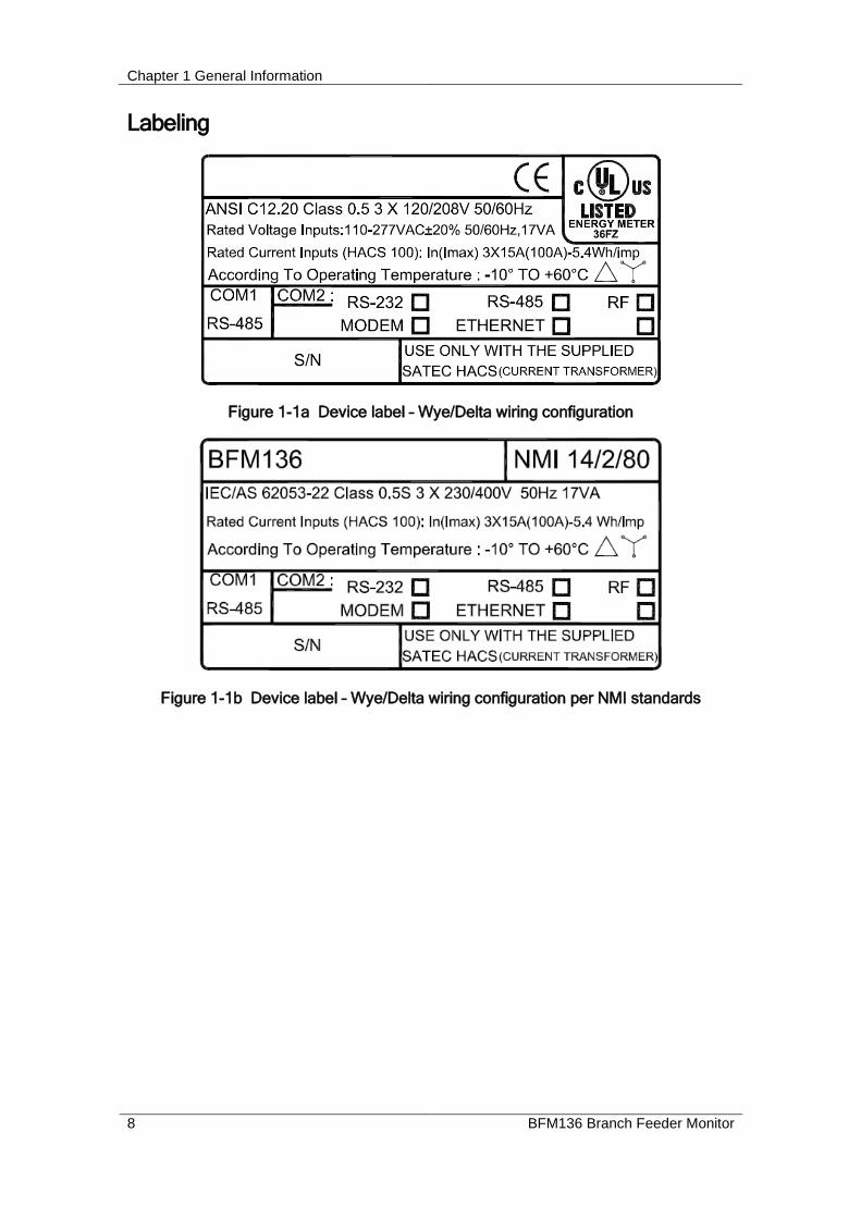
Labeling
Figure 1-1a Device label – Wye/Delta wiring configuration
Figure 1-1b Device label – Wye/Delta wiring configuration per NMI standards

Chapter 2 Installation Mechanical Installation
BFM136 Branch Feeder Monitor 9
Chapter 2 Installation
Mechanical Installation
Figure 2-1 BFM136 dimensions

Chapter 2 Installation Mechanical Installation
10 BFM136 Branch Feeder Monitor
Figure 2-2 Wall mounting
Figure 2-3 DIN rail mounting

Chapter 2 Installation
BFM136 Branch Feeder Monitor 11
Figure 2-4 Single HACS dimensions

Chapter 2 Installation Electrical Installation
12 BFM136 Branch Feeder Monitor
Electrical Installation BFM136 offers maximum flexibility of current connections by using the variety of HACS options and by wiring any HACS to any current input of the device. The following drawings present applications serviced by the BFM136.
Before installation ensure that all incoming power sources are shut OFF. Failure to observe this practice can result in serious or even fatal injury and damage to equipment.
Figure 2-5a Typical Electrical Installation – Wye wiring

Chapter 2 Installation Electrical Installation
BFM136 Branch Feeder Monitor 13
Figure 2-5b Typical Electrical Installation – Delta wiring

Chapter 2 Installation Electrical Installation
14 BFM136 Branch Feeder Monitor
Figure 2-6 Single HACS wiring and labeling
USE ONLY WITH SUPPLIED BFM CURRENT TRANSFORMERS!
Connect the wires to the + and - inlets according to the following polarity colors:
Polarity Solid Core HACS secondary Split Core HACS secondary
+ RED WHITE
- ORANGE BLACK
It is recommended to mark the cables and CTs with the supplied tie markers.
HACS stickers I1 through I36 correspond to the BFM136 current inputs with matching labels. Cable stickers 1 through 12 correspond to the BFM136 current terminal blocks with matching labels.
Use the table from Appendix B to annotate your input assignments and wiring connections.
Labeling example:
Assume you want to connect three HACSs to the device terminal block 3 so these three HACSs would be connected to the device inputs I7, I8, and I9 respectively:
1. Take a HACS connection cable, attach a tie wrap marker to each side of the cable and mark them as 3 to indicate that it should be connected to the device terminal block 3.
2. Put the HACS label stickers I7, I8, and I9 directly on HACSs to indicate that these HACSs will be associated with the device current terminals I7, I8, and I9.
Safety Requirements
To ensure safety requirements the BFM136 must be grounded - the protective ground terminal should be connected to protective earth with a copper conductor or strap with minimal length (less than 1 m desirable) and cross-section 5.3 mm2 (AWG10) at least.
Chapter 2 Installation Electrical Installation
BFM136 Branch Feeder Monitor 15
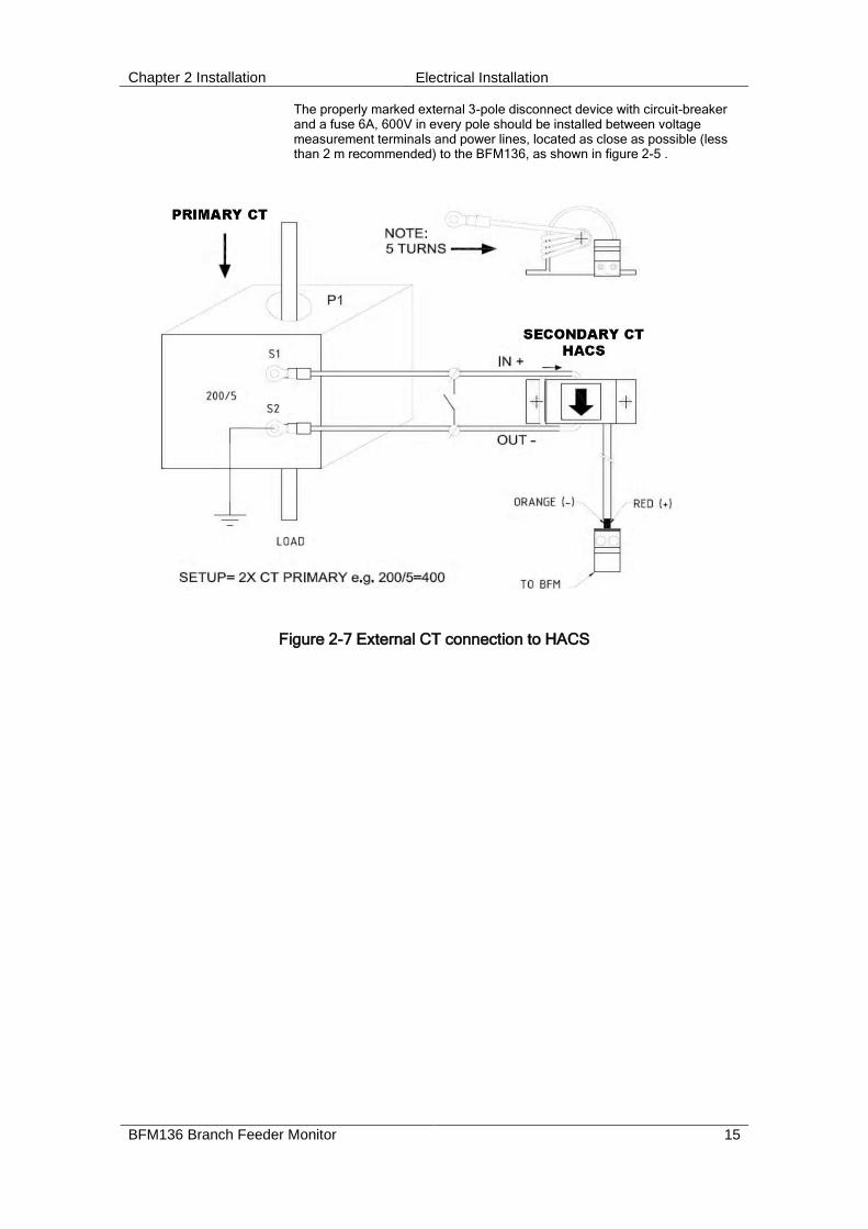
The properly marked external 3-pole disconnect device with circuit-breaker and a fuse 6A, 600V in every pole should be installed between voltage measurement terminals and power lines, located as close as possible (less than 2 m recommended) to the BFM136, as shown in figure 2-5 .
Figure 2-7 External CT connection to HACS

Chapter 2 Installation Communications
16 BFM136 Branch Feeder Monitor
Communications Several communication options are available for the BFM136.
RS485
RF
RS485
DIAL-UPMODEMTELEPHON
RS485
RS232
RS485
NONE
RS485
ETHERNET
RS485
RS485/422
+
RxTx
Figure 2-8 Communication options
RS-485 Connection
DEVICES -
+
RS-485 (PLC) PC
+
Figure 2-9 RS-485 2-wire connection

Chapter 2 Installation Communications
BFM136 Branch Feeder Monitor 17
2
BFM136 BFM136 BFM136
R t 1
MASTER
RS
-232
RX
D
TX
D
TX
EN
AB
LE
RX
D
RS
-42
2 / R
S-4
85
TX
D
PO
WE
R
UP TO 32 POWERMETERS
CABLE MAXIMUM LENGTH 1000M
RS485RS232
RS485/422-232
+
SHLD
-
CONVERTER
SHLD SHLD SHLD
Rt
SU
PP
LY
COMMUNICATION CONVERTER
NLP
OW
ER
- + - + - +
t1,R tR 2=200-500 Ohm, 0.5W
+ + +
Figure 2-10 RS-485 multidrop connection
+Tx-Tx-Rx +Rx
RS-422 COMMUNICATION PORT
4 WIRE CONNECTION
SYSTEMTO COMMUNICATION
Tx
Rx
TxRx
Figure 2-11 RS-422/485 4-wire connection

Chapter 2 Installation Communications
18 BFM136 Branch Feeder Monitor
RS232 Connection
SG
RX
TX
RxTx
51 2 3 46 87 9
Figure 2-12 RS-232 connection
COMPUTER CONNECTIONS RS-232
RS232EM610
MALE CON.
IBM PC/COMPATIBLE25-PIN DB25FEMALE CON.
IBM PC/COMPATIBLE
MALE CON.RS232EM610
9-PIN DB9FEMALE CON.
RS-232 SIMPLE 3-WIRE
CONNECTION 25-PIN CONNECTION 9-PIN
RS-232 SIMPLE 3-WIRE
Figure 2-13 RS-232 cable drawings
Modem Connection

Chapter 2 Installation Communications
BFM136 Branch Feeder Monitor 19
Ethernet Connection
RS485
ETHERNET
RF

Chapter 2 Installation Controls and Indicators
20 BFM136 Branch Feeder Monitor
Controls and Indicators
Figure 2-14 BFM136 Front View
Indicator LEDs
The flashing yellow CPU LED shows that the device is operational and is functioning normally.
The green TX and RX LEDs indicate activity on the COM1 communication port. The LEDs flash when the port is receiving or transmitting data.
Energy Pulse LED
The red “Wh” LED flashes at a user-programmed rate when a load is applied to the device. In normal mode, the LED pulses indicate imported Wh for a selected submeter. In energy test mode, the LED pulses indicate either imported Wh, or imported (inductive) varh for a selected submeter. Energy test mode is used for testing the device energy measurement accuracy. In test mode, the energy and demand accumulators do not account for consumed energy.
See Device Options in Chapter 3 and General Meter Setup in Chapter 4 on how to put the device into energy test mode and how to select the LED pulse rate and a submeter for testing.
Front Panel Display
The BFM136 is provided with an LCD display and four push buttons that are used for local meter reading and setup. See BFM136 Display Operations in Chapter 3 for information on using the front panel display.

Chapter 2 Installation Device Settings
BFM136 Branch Feeder Monitor 21
Device Settings Before operating your BFM136, provide the device with information about your particular environment. The device front display (see Display Operations (BFM136)) and the supplementary PAS software (see PAS Application Software) allow you to configure the BFM136 for your particular use.
Password
The BFM136 configuration setups are secured by a factory-preset password. Contact your dealer for your primary password. Later, you will be able to change the password via the device Access Menu (see Meter Security).
Submeter System
The BFM136 provides up to 36 submeters with separate measurement and energy registers. Each submeter can service current inputs dedicated to a particular consumer (metering submeter) or be used as a totalization meter for automatic totalization of energy from different sub-consumers (totalization submeter). Additionally, the BFM136 provides four more totalization submeters (37 through 40) that you can use for totalization purposes when all 36 metering submeters have been utilized.
A submeter remains inactive while there are no current inputs associated with the submeter (see Channel Assignments), or until you link another submeter as a source to its energy registers making it a totalization submeter (see Setting up Total and Tariff Registers). The Channel Assignment setup allows you to link one to three current inputs to each submeter and to specify the primary rating of the current transformers. A totalization submeter provides totalization of energy from any number of metering and totalization submeters.
By default, your device is configured for 12 three-phase metering submeters with 100A (maximum) current inputs (50A nominal rating).
Submeter Addressing
The BFM136 uses the Modbus communication protocol for data transmission and accessing setups through communications. A full description of the communications protocol is found in the BFM136 Modbus Reference Guide provided with your device.
Each active submeter in the BFM136 is assigned a unique communication address that allows accessing its private registers and setups. All submeter addresses are assigned automatically in a sequential order starting with the device base address that is programmed through the device Communication Setup (see Setting Up Communication Ports ). The following table illustrates submeter addressing in the device with the base address N.
Device Base Address Submeter Number Submeter Address
N SM 1 N
SM 2 N+1
…
SM 36 N+35
SM 37 N+36
…
SM 40 N+39
Your device is factory preset to address 1 and occupies the range of addresses 1 through 12, configured for 12 three-phase submeters.
NOTES
1. Device setup settings, excluding the alarm setpoints and data log setup, are shared across all submeters. Though you can read or write them using any submeter address, your changes affect all submeters in the device.
Chapter 2 Installation Device Diagnostics
22 BFM136 Branch Feeder Monitor
2. When using the ExpertPower client, submeter address 99 on the Ethernet port COM2 is reserved for the BFM136 router and must not fall inside the range of the submeter addresses for this port.
Select your submeters (both metering and totalization) in a sequence without gaps so that your device does not occupy unnecessary network addresses.
If you connect a number of devices to a serial network, allocate a range of addresses for each device so that they do not overlap. For example, if you use three devices with 12 submeters in each one, assign the base address 1 to the first device, the address 13 to the second, and the address 25 to the third device so that they will occupy three non-overlapped address ranges 1 through12, 13 through 24, and 25 through 36.
Basic Device Settings
For proper device operation, select the correct power frequency (see Basic Device Settings) and set the correct primary ratings for device current inputs (see Channel Assignments) before you connect the device to your network.
Energy/TOU System
The BFM136 provides 4 separate billing energy (total/summary and parallel tariff and maximum demand) registers for each individual submeter. Each register can be linked to any internal energy source or another submeter. The first billing register in your meter is linked to the kWh accumulator by default. Other registers are not operational unless you configure them through the Energy/TOU Setup (see Configuring Billing Energy and TOU Registers).
Device Diagnostics Device diagnostic messages may appear as a result of the BFM136 built-in diagnostic tests performed during start-up and device operation. See Device Diagnostic Codes in Appendix F for the list of diagnostic codes and their meanings.
The device diagnostics status is stored in a non-volatile register, which may be inspected and cleared via PAS, from the meter display or from a user application. All diagnostic events with time stamps are also recorded in the device Event log and can be inspected via PAS (see Retrieving the Event Log in Chapter 4).
See Diagnostics Display and Reset in Chapter 3 on how to inspect and clear the device diagnostics status from the display. See Viewing and Clearing Device Diagnostics in Chapter 4 on how to inspect and clear the device diagnostics status via PAS. Refer to the BFM136 Modbus Reference Guide for the diagnostic register address and layout.
In the event of a device fault, check the fault reason and clear the device diagnostics. In the event of a time fault, update the device clock. In the event of a configuration reset, check the setup affected by the fault via the device Event log, and then verify the setup data.
Hardware failures are normally non-critical recoverable faults that do not cause a system failure but may cause data loss. Hardware failures are often caused by excessive electrical noise in the region of the device.
If the device continuously resets itself, contact your local distributor.

Chapter 3 BFM136 Display Operations Startup Diagnostics
BFM136 Branch Feeder Monitor 23
Chapter 3 BFM136 Display Operations
Startup Diagnostics After applying power to the meter, a start-up diagnostic message is displayed for one second. “Power Up” indicates a normal power-up sequence. You can observe the list of device diagnostic codes recorded during restart and device operation via the Status Display.
See Device Diagnostic Codes in Appendix F for the list of diagnostic messages.
Display Features The multifunctional 2x16 alphanumeric LCD display with backlight allows easy read outs of the measurement parameters both in the dark and under sunlight. The menu-driven multi-page display allows viewing numerous measurement parameters by scrolling through display screens and pages.
Submeter Displays
In display mode, the display shows readings for the currently selected submeter. Its number is indicated at the upper-left corner of the display. To scroll through active submeters, press and hold the SELECT button, and then use the UP/DOWN buttons to move to another submeter.
Display Update
The display is updated by default once per second; you can adjust the display update rate via the Display Setup Menu.
Auto Return
If no buttons are pressed for 5 minutes and the display Auto Return option is not disabled, the display will automatically return to the real-time screen mode from any other measurement display or programming mode. The Auto Return option can be disabled through the Display Setup Menu.
Auto Scroll
If no buttons are pressed for 30 seconds while the display is in the real-time screen mode, and the Auto Scroll option is enabled in the BFM136, the measurement display will scroll automatically through all submeters. The scroll interval can be adjusted through the Display Setup Menu. To stop auto scrolling, press any button.
Backlight
If no buttons are pressed for 1 minute, the BFM136 turns the backlight off. To restore the backlight, press any button briefly.
Navigation Buttons The BFM136 has four push buttons that are normally used to navigate between screen modes and pages. In programming mode, the buttons allow you to navigate through device setup menus and to change the device settings.
The SELECT button functionality:
In display mode
Hold down the SELECT button, and then use the UP or DOWN button to scroll through the submeters.
Chapter 3 BFM136 Display Operations Display Views
24 BFM136 Branch Feeder Monitor
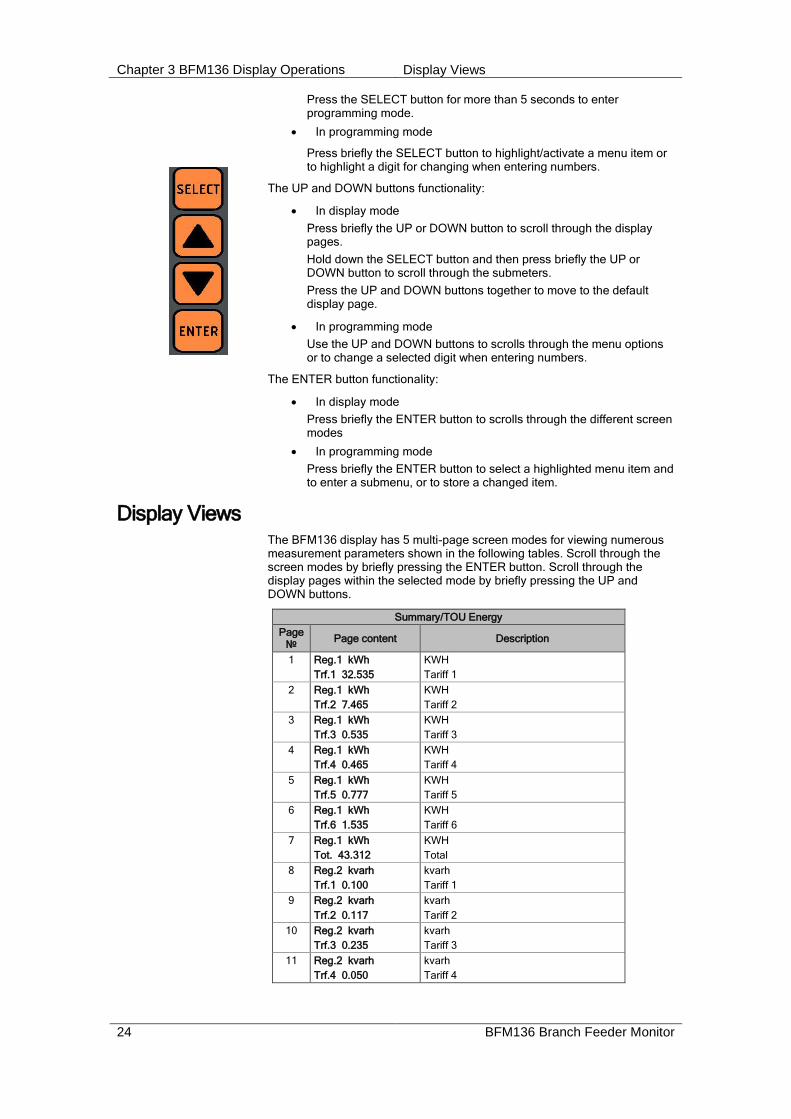
Press the SELECT button for more than 5 seconds to enter programming mode.
In programming mode
Press briefly the SELECT button to highlight/activate a menu item or to highlight a digit for changing when entering numbers.
The UP and DOWN buttons functionality:
In display mode
Press briefly the UP or DOWN button to scroll through the display pages.
Hold down the SELECT button and then press briefly the UP or DOWN button to scroll through the submeters.
Press the UP and DOWN buttons together to move to the default display page.
In programming mode
Use the UP and DOWN buttons to scrolls through the menu options or to change a selected digit when entering numbers.
The ENTER button functionality:
In display mode
Press briefly the ENTER button to scrolls through the different screen modes
In programming mode
Press briefly the ENTER button to select a highlighted menu item and to enter a submenu, or to store a changed item.
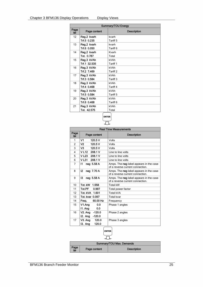
Display Views The BFM136 display has 5 multi-page screen modes for viewing numerous measurement parameters shown in the following tables. Scroll through the screen modes by briefly pressing the ENTER button. Scroll through the display pages within the selected mode by briefly pressing the UP and DOWN buttons.
Summary/TOU Energy
Page №
Page content Description
1 Reg.1 kWh
Trf.1 32.535
KWH
Tariff 1
2 Reg.1 kWh
Trf.2 7.465
KWH
Tariff 2
3 Reg.1 kWh
Trf.3 0.535
KWH
Tariff 3
4 Reg.1 kWh
Trf.4 0.465
KWH
Tariff 4
5 Reg.1 kWh
Trf.5 0.777
KWH
Tariff 5
6 Reg.1 kWh
Trf.6 1.535
KWH
Tariff 6
7 Reg.1 kWh
Tot. 43.312
KWH
Total
8 Reg.2 kvarh
Trf.1 0.100
kvarh
Tariff 1
9 Reg.2 kvarh
Trf.2 0.117
kvarh
Tariff 2
10 Reg.2 kvarh
Trf.3 0.235
kvarh
Tariff 3
11 Reg.2 kvarh
Trf.4 0.050
kvarh
Tariff 4
Chapter 3 BFM136 Display Operations Display Views
BFM136 Branch Feeder Monitor 25
Summary/TOU Energy
Page №
Page content Description
12 Reg.2 kvarh
Trf.5 0.235
kvarh
Tariff 5
13 Reg.2 kvarh
Trf.6 0.050
kvarh
Tariff 6
14 Reg.2 kvarh
Tot. 0.787
Kvarh
Total
15 Reg.3 kVAh
Trf.1 32.535
kVAh
Tariff 1
16 Reg.3 kVAh
Trf.2 7.469
kVAh
Tariff 2
17 Reg.3 kVAh
Trf.3 0.584
kVAh
Tariff 3
18 Reg.3 kVAh
Trf.4 0.468
kVAh
Tariff 4
19 Reg.3 kVAh
Trf.5 0.584
kVAh
Tariff 5
20 Reg.3 kVAh
Trf.6 0.468
kVAh
Tariff 6
21 Reg.3 kVAh
Tot. 42.575
kVAh
Total
Real Time Measurements
Page №
Page content Description
1 V1 120.5 V Volts
2 V2 120.5 V Volts
3 V3 120.5 V Volts
4 V L12 208.1 V Line to line volts
5 V L23 208.1 V Line to line volts
6 V L31 208.1 V Line to line volts
7 I1 neg 5.58 A Amps. The neg label appears in the case of a reverse current connection.
8 I2 neg 7.70 A Amps. The neg label appears in the case of a reverse current connection.
9 I3 neg 5.58 A Amps. The neg label appears in the case of a reverse current connection.
10 Tot. kW 1.558 Total kW
11 Tot.PF 0.997 Total power factor
12 Tot. kVA 1.601 Total kVA
13 Tot. kvar 0.097 Total kvar
14 Freq. 60.00 Hz Frequency
15 V1.Ang 0.0
I1. Ang 0.0
Phase 1 angles
16 V2. Ang -120.0
I2. Ang -120.0
Phase 2 angles
17 V3. Ang 120.0
I3. Ang 120.0
Phase 3 angles
Summary/TOU Max. Demands
Page №
Page content Description
ENTER
ENTER

Chapter 3 BFM136 Display Operations Display Views
26 BFM136 Branch Feeder Monitor
Summary/TOU Max. Demands
Page №
Page content Description
1 Reg.1 MD kW
Trf.1 32.535
KW maximum demand
Tariff 1
2 Reg.1 MD kW
Trf.2 7.465
KW maximum demand
Tariff 2
3 Reg.1 MD kW
Trf.3 0.535
KW maximum demand
Tariff 3
4 Reg.1 MD kW
Trf.4 0.465
KW maximum demand
Tariff 4
5 Reg.1 MD kW
Trf.5 0.535
KW maximum demand
Tariff 5
6 Reg.1 MD kW
Trf.6 0.465
KW maximum demand
Tariff 6
7 Reg.1 MD kW
Tot. 42.000
KW maximum demand
Total
8 Reg.2 MD kvar
Trf.1 0.100
kvar maximum demand
Tariff 1
9 Reg.2 MD kvar
Trf.2 0.117
kvar maximum demand
Tariff 2
10 Reg.2 MD kvar
Trf.3 0.235
kvar maximum demand
Tariff 3
11 Reg.2 MD kvar
Trf.4 0.050
kvar maximum demand
Tariff 4
12 Reg.2 MD kvar
Trf.5 0.235
kvar maximum demand
Tariff 5
13 Reg.2 MD kvar
Trf.6 0.050
kvar maximum demand
Tariff 6
14 Reg.2 MD kvar
Tot. 0.787
kvar maximum demand
Total
15 Reg.3 MD kVA
Trf.1 32.535
kVA maximum demand
Tariff 1
16 Reg.3 MD kVA
Trf.2 7.469
kVA maximum demand
Tariff 2
17 Reg.3 MD kVA
Trf.3 0.584
kVA maximum demand
Tariff 3
18 Reg.3 MD kVA
Trf.4 0.468
kVA maximum demand
Tariff 4
19 Reg.3 MD kVA
Trf.5 0.584
kVA maximum demand
Tariff 5
20 Reg.3 MD kVA
Trf.6 0.468
kVA maximum demand
Tariff 6
21 Reg.3 MD kVA
Tot. 42.575
kVA maximum demand
Total
ENTER
Chapter 3 BFM136 Display Operations Display Views
BFM136 Branch Feeder Monitor 27
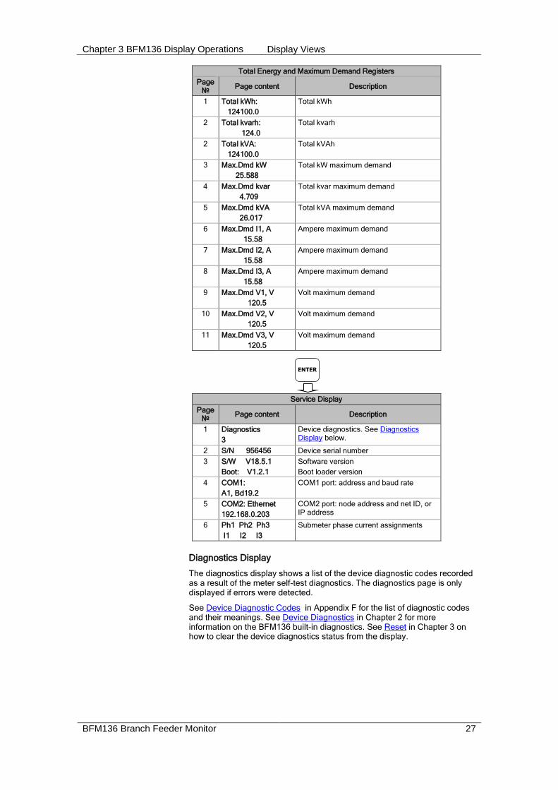
Total Energy and Maximum Demand Registers
Page №
Page content Description
1 Total kWh:
124100.0
Total kWh
2 Total kvarh:
124.0
Total kvarh
2 Total kVA:
124100.0
Total kVAh
3 Max.Dmd kW
25.588
Total kW maximum demand
4 Max.Dmd kvar
4.709
Total kvar maximum demand
5 Max.Dmd kVA
26.017
Total kVA maximum demand
6 Max.Dmd I1, A
15.58
Ampere maximum demand
7 Max.Dmd I2, A
15.58
Ampere maximum demand
8 Max.Dmd I3, A
15.58
Ampere maximum demand
9 Max.Dmd V1, V
120.5
Volt maximum demand
10 Max.Dmd V2, V
120.5
Volt maximum demand
11 Max.Dmd V3, V
120.5
Volt maximum demand
Service Display
Page №
Page content Description
1 Diagnostics
3
Device diagnostics. See Diagnostics Display below.
2 S/N 956456 Device serial number
3 S/W V18.5.1
Boot: V1.2.1
Software version
Boot loader version
4 COM1:
A1, Bd19.2
COM1 port: address and baud rate
5 COM2: Ethernet
192.168.0.203
COM2 port: node address and net ID, or IP address
6 Ph1 Ph2 Ph3
I1 I2 I3
Submeter phase current assignments
Diagnostics Display
The diagnostics display shows a list of the device diagnostic codes recorded as a result of the meter self-test diagnostics. The diagnostics page is only displayed if errors were detected.
See Device Diagnostic Codes in Appendix F for the list of diagnostic codes and their meanings. See Device Diagnostics in Chapter 2 for more information on the BFM136 built-in diagnostics. See Reset in Chapter 3 on how to clear the device diagnostics status from the display.
ENTER

Chapter 3 BFM136 Display Operations Navigating in Menus
28 BFM136 Branch Feeder Monitor
Navigating in Menus The BFM136 setup is menu-driven. To enter the setup menus, press the SELECT button for more than 5 seconds.
Entering Numbers
Each digit in numbers is adjusted separately with the UP/DOWN buttons. A brief press on the button increments or decrements the highlighted digit by one. A highlighted digit is flashing twice per second. To move to the next digit, press briefly the SELECT button.
When the number is set to a desired value, press briefly the ENTER button to store your new setting.
Entering a Password
The setup menus are secured by an 8-digit user password. If the password entered is correct, you will move to the main menu, otherwise you will return to the display mode.
Selecting Menus
The main menu is represented by two entries; the left item shows a menu list, while the right item is an assisting exit window that allows easy returning to the display mode. Flashing highlights a currently active menu item (in the following diagrams, a highlighted item is pointed out by using a bold font). To highlight a desired menu item, press briefly the SELECT button.
To select a menu entry from the menu list:
1. Highlight the left item by briefly pressing the SELECT button if it is not highlighted yet.
2. Scroll through the menu list by briefly pressing the UP and DOWN buttons until the desired menu entry appears.
3. Press the ENTER button.
To exit the main menu:
1. Highlight the Exit item by briefly pressing the SELECT button.
2. Press the ENTER button.
Enter Password 00000000
Options Exit
COM1 Exit
ENTER
COM1 Protocol Modbus RTU
Options Exit
Options Exit
ENTER
SELECT

Chapter 3 BFM136 Display Operations Menu Operations
BFM136 Branch Feeder Monitor 29
Viewing and Changing Setup Items
A second level menu normally consists of three items: the upper-left static item indicates the menu name, while the upper-right item represents a list of setup parameters you can scroll through, and the lower item shows the present parameter value.
To select a parameter you want to view or change:
1. Highlight the upper-right item by briefly pressing the SELECT button if the item is not highlighted yet.
2. Scroll through the parameter list with the UP/DOWN buttons until the desired parameter name appears.
To change the selected parameter:
1. Press the SELECT button briefly to highlight the lower item.
2. If a number represents the parameter value, highlight a desired digit by briefly pressing the SELECT button, then adjust the digit to the desired value by the UP and DOWN buttons.
3. If a name represents the parameter value, select the desired value by the UP and DOWN buttons.
4. Press the ENTER button to store your selection. You return to the parameter list to select another parameter or return to the main menu.
To exit the menu:
1. Highlight the menu name (upper-left item) by pressing briefly the SELECT button.
2. Press the ENTER button.
Menu Operations
Submeter Channel Assignments
This menu allows you to link the device current terminals to submeters so they can monitor them. Additionally, the menu allows you to specify the primary current rating of the current transformers connected to the device terminals. The number of the selected current inputs for a submeter specifies if it will be a single-, two-, or three-phase meter.
Always select your submeters in a sequence without gaps so that your device does not occupy unnecessary network addresses.
To enter the menu, select the SubMeter entry from the main menu, and then press the ENTER button.
To select a parameter you want to view or change:
1. Highlight the upper-right item by using the SELECT button.
2. Select the submeter you wish to configure with the UP/DOWN buttons.
3. Highlight the lower-left item by briefly pressing the SELECT button.
4. Scroll through the parameter list with the UP/DOWN buttons until the desired parameter name appears.
To change the selected parameter:
1. Highlight the lower-right item by using the SELECT button.
COM1 Protocol Modbus RTU
COM1 Address 1
SELECT
COM1 Address 001
COM1 Address 126
ENTER
COM1 Address 126
COM1 Exit
ENTER
SubMeter Exit
SubMeter SM 1
Phase L1 I1
ENTER
SubMeter SM 4 Phase L1 I1
SELECT
SubMeter SM 4 Phase L1 I1
Chapter 3 BFM136 Display Operations Menu Operations
30 BFM136 Branch Feeder Monitor
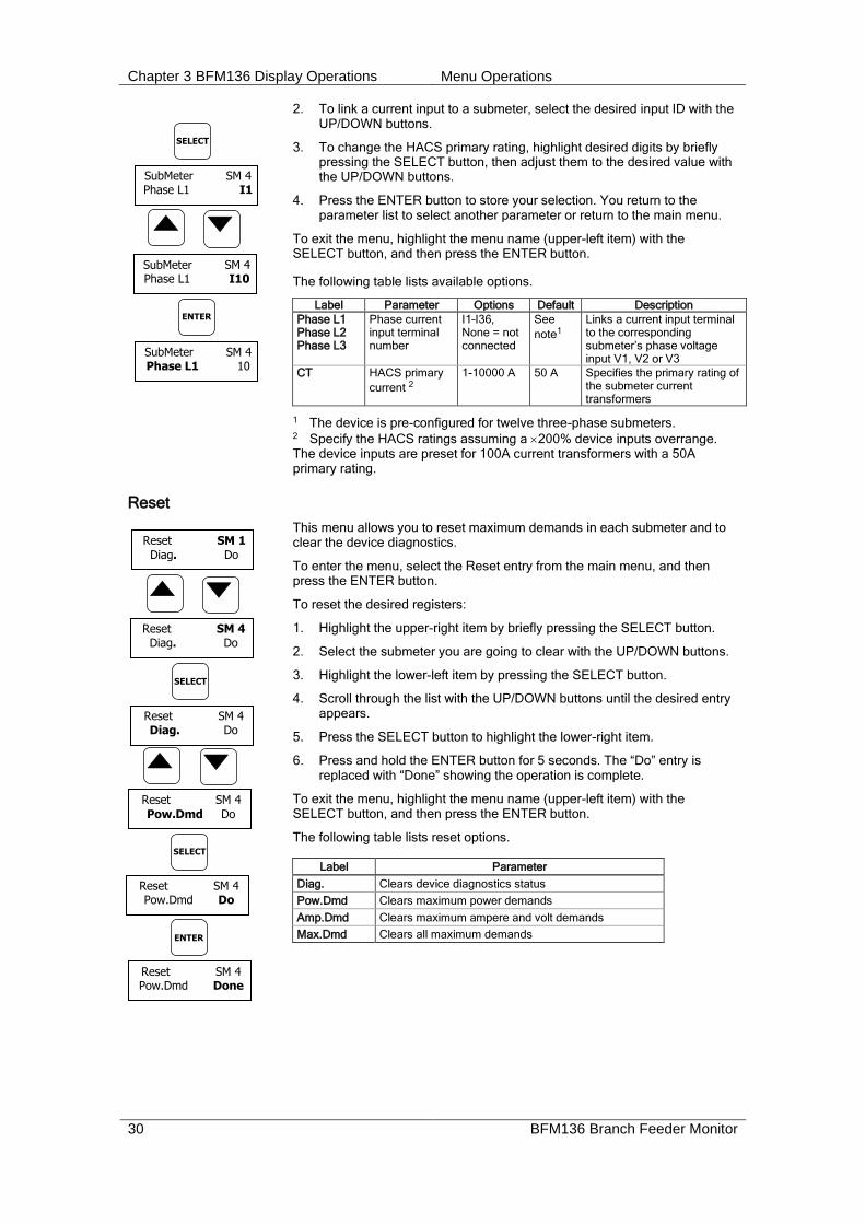
2. To link a current input to a submeter, select the desired input ID with the UP/DOWN buttons.
3. To change the HACS primary rating, highlight desired digits by briefly pressing the SELECT button, then adjust them to the desired value with the UP/DOWN buttons.
4. Press the ENTER button to store your selection. You return to the parameter list to select another parameter or return to the main menu.
To exit the menu, highlight the menu name (upper-left item) with the SELECT button, and then press the ENTER button.
The following table lists available options.
Label Parameter Options Default Description
Phase L1 Phase L2 Phase L3
Phase current input terminal number
I1–I36, None = not connected
See
note1
Links a current input terminal to the corresponding submeter’s phase voltage input V1, V2 or V3
CT HACS primary
current 2
1-10000 A 50 A Specifies the primary rating of the submeter current transformers
1 The device is pre-configured for twelve three-phase submeters. 2 Specify the HACS ratings assuming a 200% device inputs overrange. The device inputs are preset for 100A current transformers with a 50A primary rating.
Reset
This menu allows you to reset maximum demands in each submeter and to clear the device diagnostics.
To enter the menu, select the Reset entry from the main menu, and then press the ENTER button.
To reset the desired registers:
1. Highlight the upper-right item by briefly pressing the SELECT button.
2. Select the submeter you are going to clear with the UP/DOWN buttons.
3. Highlight the lower-left item by pressing the SELECT button.
4. Scroll through the list with the UP/DOWN buttons until the desired entry appears.
5. Press the SELECT button to highlight the lower-right item.
6. Press and hold the ENTER button for 5 seconds. The “Do” entry is replaced with “Done” showing the operation is complete.
To exit the menu, highlight the menu name (upper-left item) with the SELECT button, and then press the ENTER button.
The following table lists reset options.
Label Parameter
Diag. Clears device diagnostics status
Pow.Dmd Clears maximum power demands
Amp.Dmd Clears maximum ampere and volt demands
Max.Dmd Clears all maximum demands
Reset SM 1
Diag. Do
Reset SM 4 Diag. Do
Reset SM 4 Diag. Do
Reset SM 4
Pow.Dmd Do
ENTER
Reset SM 4 Pow.Dmd Do
SELECT
SELECT
Reset SM 4 Pow.Dmd Done
SELECT
SubMeter SM 4 Phase L1 I1
SubMeter SM 4 Phase L1 I10
ENTER
SubMeter SM 4 Phase L1 10

Chapter 3 BFM136 Display Operations Menu Operations
BFM136 Branch Feeder Monitor 31
Real Time Clock Setting
This menu allows you to adjust internal real time clock.
To enter the menu, select the RTC entry from the main menu, and then press the ENTER button.
To adjust the clock:
1. Highlight a time or date item you want to change item by briefly pressing the SELECT button.
2. Adjust the selected item with the UP/DOWN buttons.
3. Highlight the next item you want to change and adjust it in the same manner.
4. To store your new date and time, press the ENTER button. If you confirm the time change while the seconds item is highlighted, the seconds’ reading will be zeroed, otherwise seconds stay unchanged.
To exit the menu, highlight the menu name (upper-left item) with the SELECT button, and then press the ENTER button.
Basic Device Settings
This menu allows you to define the general characteristics of the electrical network.
To enter the menu, select the Basic entry from the main menu, and then press the ENTER button. For instructions on navigating in the menu, see Viewing and Changing Setup Items.
The following table lists available options.
Label Parameter Options Default Description
Pt PT Ratio 1.0-6500.0 1.0 The phase potential transformer’s primary to secondary ratio
Frequency Nominal frequency
50, 60 Hz 60 Hz The nominal power frequency
PowDmdPer Block power demand period
1, 2, 5, 10, 15, 20, 30, 60 min
30 The length of the demand period for power demand calculations
Num.Per. The number of blocks in the sliding window
1-15 1 The number of blocks to be averaged for sliding window demands
VDmnPer. Volt demand period
0-9000 sec 900 The length of the demand period for volt demand calculations
ADmdPer. Ampere demand period
0-9000 sec 900 The length of the demand period for ampere demand calculations
Transformer Correction
Transformer correction allows you to compensate ratio and phase angle inaccuracies of the user voltage and current instrument transformers. To enter the menu, select the T.Corr. entry from the main menu, and then press the ENTER button. For instructions on navigating in the menu, see Viewing and Changing Setup Items.
The following table lists available options.
RTC Jun 06,2005
Time 20:47:06
SELECT
RTC Jun 06,2005 Time 20:47:06
RTC Jun 06,2006 Time 20:47:06
ENTER
RTC Jun 06,2006 Time 20:47:06
Basic Exit
Basic Frequency
60
ENTER

Chapter 3 BFM136 Display Operations Menu Operations
32 BFM136 Branch Feeder Monitor
Label Parameter Options Default Description
Ratio V1-V3 V1-V3 voltage transformer ratio correction factor
0.700 to 1.300 1.000 The ratio of the true transformer ratio to the marked ratio.
Angle V1-V3
V1-V3 transformer phase angle error, minutes
-600 to 600
0 The phase
displacement, in minutes, between the primary and secondary values. The phase angle of a voltage transformer is positive when the secondary value leads the primary value.
Ratio I1-I36 I1-I36 current transformer ratio correction factor
0.700 to 1.300 1.000 The ratio of the true transformer ratio to the marked ratio.
Angle I1-I36
I1-I36 transformer phase angle error, minutes
-600 to 600
0 The phase
displacement, in minutes, between the primary and secondary values. The phase angle of a current transformer is positive when the secondary value leads the primary value.
Device Options
This menu allows you to select some user-configurable device options or put the BFM136 into energy test mode.
To enter the menu, select the Options entry from the main menu, then press ENTER. For instructions on navigating in the menu, see Viewing and Changing Setup Items.
The following table lists available options.
Label Parameter Options Default Description
PowMode Power calculation mode
Reactive, NonActive (non-active power)
Reactive The method used for calculating reactive and apparent powers
ErgyRoll Energy roll value
100000.0- 100000000.0
kWh
100000000.0 The value at which energy counters roll over to zero
TestMode Energy test mode
OFF, Wh, varh OFF Setting this option puts the device into the energy test mode
PlsConst Wh LED pulse rate, Wh/pulse
0.01-100.00 5.40Wh/pulse (one equivalent disk revolution)
LED pulse constant - the amount of accumulated energy giving one pulse via “Wh” LED
WhLEDSrc Energy LED source
1-40, None 1 Selects a submeter as a LED pulsing source
Communication Ports
These two menus allow you to configure parameters for communication ports COM1 and COM2. The BFM136 automatically detects a replaceable communication module and will not allow you to change the baud rate and data format for the Dial-up modem, and for the Ethernet and RF modules.
Options Exit
Options PowMode Reactive
ENTER
Chapter 3 BFM136 Display Operations Menu Operations
BFM136 Branch Feeder Monitor 33
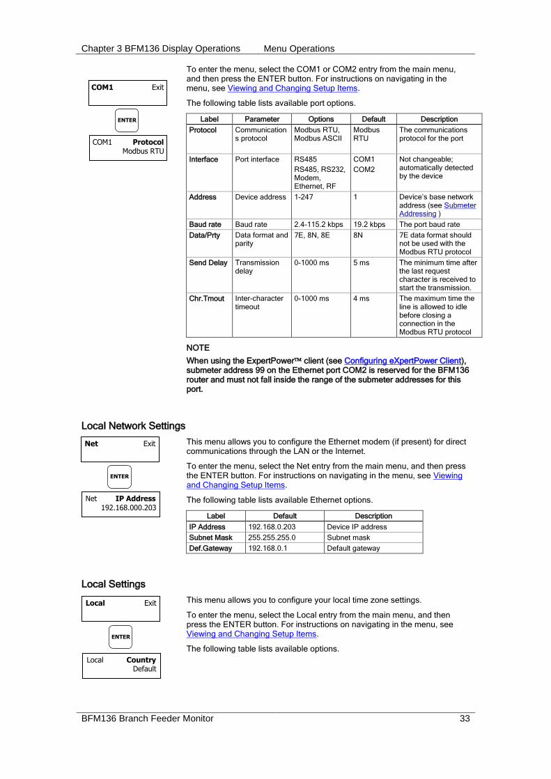
To enter the menu, select the COM1 or COM2 entry from the main menu, and then press the ENTER button. For instructions on navigating in the menu, see Viewing and Changing Setup Items.
The following table lists available port options.
Label Parameter Options Default Description
Protocol Communications protocol
Modbus RTU, Modbus ASCII
Modbus RTU
The communications protocol for the port
Interface Port interface RS485
RS485, RS232, Modem, Ethernet, RF
COM1
COM2
Not changeable; automatically detected by the device
Address Device address 1-247 1 Device’s base network address (see Submeter Addressing )
Baud rate Baud rate 2.4-115.2 kbps 19.2 kbps The port baud rate
Data/Prty Data format and parity
7E, 8N, 8E 8N 7E data format should not be used with the Modbus RTU protocol
Send Delay Transmission delay
0-1000 ms 5 ms The minimum time after the last request character is received to start the transmission.
Chr.Tmout Inter-character timeout
0-1000 ms 4 ms The maximum time the line is allowed to idle before closing a connection in the Modbus RTU protocol
NOTE
When using the ExpertPower client (see Configuring eXpertPower Client), submeter address 99 on the Ethernet port COM2 is reserved for the BFM136 router and must not fall inside the range of the submeter addresses for this port.
Local Network Settings
This menu allows you to configure the Ethernet modem (if present) for direct communications through the LAN or the Internet.
To enter the menu, select the Net entry from the main menu, and then press the ENTER button. For instructions on navigating in the menu, see Viewing and Changing Setup Items.
The following table lists available Ethernet options.
Label Default Description
IP Address 192.168.0.203 Device IP address
Subnet Mask 255.255.255.0 Subnet mask
Def.Gateway 192.168.0.1 Default gateway
Local Settings
This menu allows you to configure your local time zone settings.
To enter the menu, select the Local entry from the main menu, and then press the ENTER button. For instructions on navigating in the menu, see Viewing and Changing Setup Items.
The following table lists available options.
COM1 Exit
COM1 Protocol Modbus RTU
ENTER
Net Exit
Net IP Address
192.168.000.203
ENTER
Local Exit
Local Country Default
ENTER
Chapter 3 BFM136 Display Operations Menu Operations
34 BFM136 Branch Feeder Monitor
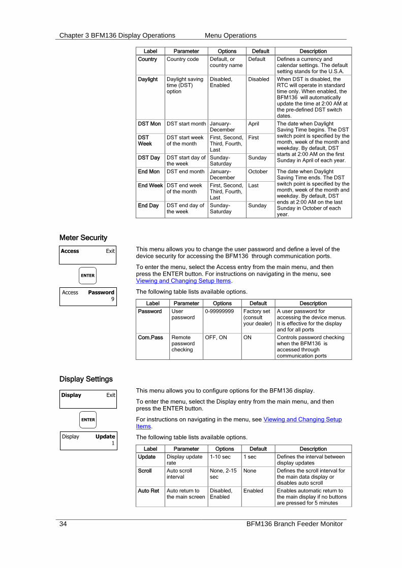
Label Parameter Options Default Description
Country Country code Default, or country name
Default Defines a currency and calendar settings. The default setting stands for the U.S.A.
Daylight Daylight saving time (DST) option
Disabled, Enabled
Disabled When DST is disabled, the RTC will operate in standard time only. When enabled, the BFM136 will automatically update the time at 2:00 AM at the pre-defined DST switch dates.
DST Mon DST start month January-December
April The date when Daylight Saving Time begins. The DST switch point is specified by the month, week of the month and weekday. By default, DST starts at 2:00 AM on the first Sunday in April of each year.
DST Week
DST start week of the month
First, Second, Third, Fourth, Last
First
DST Day DST start day of the week
Sunday-Saturday
Sunday
End Mon DST end month January-December
October The date when Daylight Saving Time ends. The DST switch point is specified by the month, week of the month and weekday. By default, DST ends at 2:00 AM on the last Sunday in October of each year.
End Week DST end week of the month
First, Second, Third, Fourth, Last
Last
End Day DST end day of the week
Sunday-Saturday
Sunday
Meter Security
This menu allows you to change the user password and define a level of the device security for accessing the BFM136 through communication ports.
To enter the menu, select the Access entry from the main menu, and then press the ENTER button. For instructions on navigating in the menu, see Viewing and Changing Setup Items.
The following table lists available options.
Label Parameter Options Default Description
Password User password
0-99999999 Factory set (consult your dealer)
A user password for accessing the device menus. It is effective for the display and for all ports
Com.Pass Remote password checking
OFF, ON ON Controls password checking when the BFM136 is accessed through communication ports
Display Settings
This menu allows you to configure options for the BFM136 display.
To enter the menu, select the Display entry from the main menu, and then press the ENTER button.
For instructions on navigating in the menu, see Viewing and Changing Setup Items.
The following table lists available options.
Label Parameter Options Default Description
Update Display update rate
1-10 sec 1 sec Defines the interval between display updates
Scroll Auto scroll interval
None, 2-15 sec
None Defines the scroll interval for the main data display or disables auto scroll
Auto Ret Auto return to the main screen
Disabled, Enabled
Enabled Enables automatic return to the main display if no buttons are pressed for 5 minutes
Access Exit
Access Password
9
ENTER
Display Exit
Display Update 1
ENTER

Chapter 3 BFM136 Display Operations Menu Operations
BFM136 Branch Feeder Monitor 35
Label Parameter Options Default Description
Backlit Backlight control
Off, On Off ON - the backlight is still lights all the time.
OFF - the backlight is turned off in 1 minute if no button is pressed.
Chapter 4 PAS Application Software Setting up your Submeters
36 BFM136 Branch Feeder Monitor
Chapter 4 PAS Application Software The supplemental PAS software can be used for configuring the BFM136 through communication ports, for retrieving real-time and energy profile data, and for remote upgrading device firmware.
To run PAS, you need Windows 98, Windows NT, Windows 2000 or Windows XP installed on your computer. PAS will not run properly on Windows 95.
For information on how to install PAS on your PC, see the PAS Getting Started guide supplied on the installation CD.
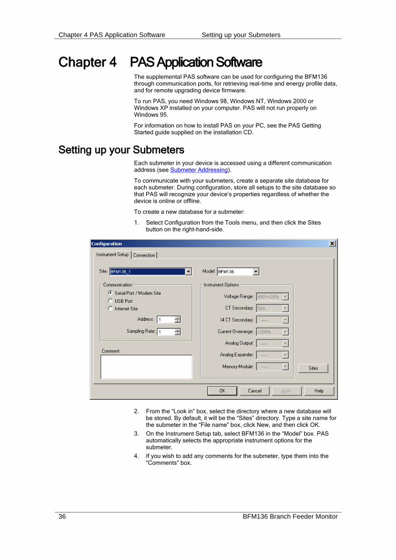
Setting up your Submeters Each submeter in your device is accessed using a different communication address (see Submeter Addressing).
To communicate with your submeters, create a separate site database for each submeter. During configuration, store all setups to the site database so that PAS will recognize your device’s properties regardless of whether the device is online or offline.
To create a new database for a submeter:
1. Select Configuration from the Tools menu, and then click the Sites button on the right-hand-side.
2. From the “Look in” box, select the directory where a new database will be stored. By default, it will be the “Sites” directory. Type a site name for the submeter in the “File name” box, click New, and then click OK.
3. On the Instrument Setup tab, select BFM136 in the “Model” box. PAS automatically selects the appropriate instrument options for the submeter.
4. If you wish to add any comments for the submeter, type them into the “Comments” box.
Chapter 4 PAS Application Software Setting up Communications
BFM136 Branch Feeder Monitor 37
Setting up Communications You can communicate with your meter via a local RS-485 serial port, or remotely through a second adjustable communication port. Depending on what was ordered, your meter may be equipped with an RS-232 or RS-422/485 serial port, with a dial-up modem for communicating through public telephone lines, with an Ethernet module for communicating through the Internet, or with an RF modem for wireless communications.
The communication protocol and port settings in PAS must match the settings made in your device.
To configure your communications with the BFM136 :
1. Select Configuration from the Tools menu. Under the Communication group on the Instrument Setup tab, select the type of connection for your device.
2. In the Address box, select an appropriate submeter address.
3. In the Sampling Rate box, select a rate at which PAS updates data on your screen when you continuously poll the device via the PAS Data Monitor.
Communicating through a Serial Port
Select Serial Port/Modem Site on the Configuration tab, and then click on the Connection tab to configure your serial port settings.
Configuring a Serial Port
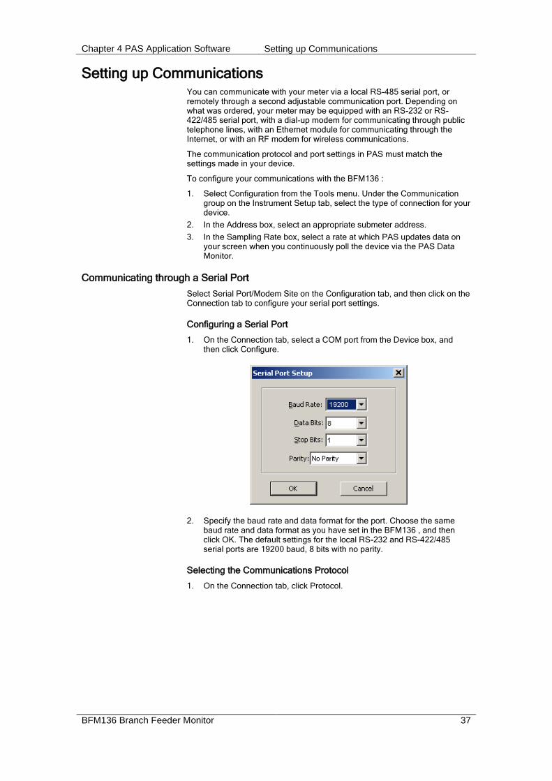
1. On the Connection tab, select a COM port from the Device box, and then click Configure.
2. Specify the baud rate and data format for the port. Choose the same baud rate and data format as you have set in the BFM136 , and then click OK. The default settings for the local RS-232 and RS-422/485 serial ports are 19200 baud, 8 bits with no parity.
Selecting the Communications Protocol
1. On the Connection tab, click Protocol.

Chapter 4 PAS Application Software Setting up Communications
38 BFM136 Branch Feeder Monitor
2. In the Protocol box, select the same communications protocol as you have in your BFM136 . The default protocol setting in the BFM136 for all ports is Modbus RTU.
For more information on configuring the protocol parameters, refer to the PAS Getting Started guide.
Communicating through the Internet
If you are communicating via the Ethernet, define the IP address of your BFM136 on the network.
1. On the Instrument Setup tab, select Internet Site.
2. Click on the Connection tab.
3. Click IP address and type in the IP address of your BFM136 . The
factory-set IP address is 192.168.0.203.
4. In the Protocol box, select Modbus RTU. The default host port 502 is set automatically as you select the protocol.
5. In the Wait for answer box, adjust the time that PAS will wait for a connection before announcing an error and the number of retries PAS will use to receive a response from the device if communications fail.
Chapter 4 PAS Application Software Preparing Setups
BFM136 Branch Feeder Monitor 39
Preparing Setups PAS allows you to prepare setup data for your BFM136 off-line without the need to have it connected to your PC.
Select the appropriate site from the list box on the PAS toolbar, and then select the desired setup group from the Meter Setup menu. Click on the tab with the setup you want to create or modify, and then fill in the boxes with the desired configuration data. Click the “Save as…” button to store the data to the site database.
To save your setup to another site database, select it from the file pane. Click OK.
To reuse setups from another site, copy them to your present site database. Click Open, select the desired site database, and click OK. The opened setup is copied to your site database.
You can also copy all setups from one site database into another site's database. Select a device site from the list box on the toolbar from which you want to reproduce setups, and then select “Copy to...” from the Meter Setup menu. Select the site database to which to copy setups, and then click OK.
Downloading Setups
You can update each setup in your BFM136 one at time or download all setups together from the site database.
To update a particular setup, check the On-line button on the PAS toolbar, select a submeter site from the list box on the toolbar, and then select the desired setup group from the Meter Setup menu. Click on the tab of the setup you want to download to the device, and then click Send.
To download all setups at once, check the On-line button on the toolbar, select the submeter site from the list box on the toolbar, and then select Download Setups from the Meter Setup menu.
Device setup settings, excluding the alarm setpoints and data log setup, are shared across all submeters. Though you can download them to the device using any submeter address, your changes affect all submeters in the device.
The alarm setpoints and data log setup must be downloaded separately to every submeter using its local address. If you wish to download the same settings to all submeters in your device, prepare the alarm setpoints and/or data log setup for one of the submeters and store them to its site database, select the submeter site from the list box on the toolbar, and then click Download to all Submeters on the Meter Setup menu.
Uploading Setups
To upload the setups from the submeter to the site database, check the On-line button on the PAS toolbar, select the submeter site from the list box on the toolbar, and then select Upload Setups from the Meter Setup menu.
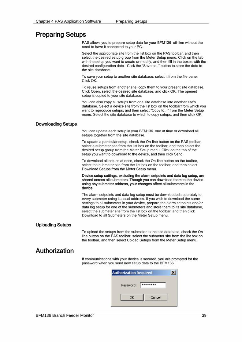
Authorization If communications with your device is secured, you are prompted for the password when you send new setup data to the BFM136 .
Chapter 4 PAS Application Software Changing Port Settings
40 BFM136 Branch Feeder Monitor
Enter the password and click OK. If your authorization was successful, you are not prompted for the password again until you close the dialog window.
Changing Port Settings This section describes how to configure communication ports in the BFM136 through PAS.
The communication settings affect all submeters in your device.
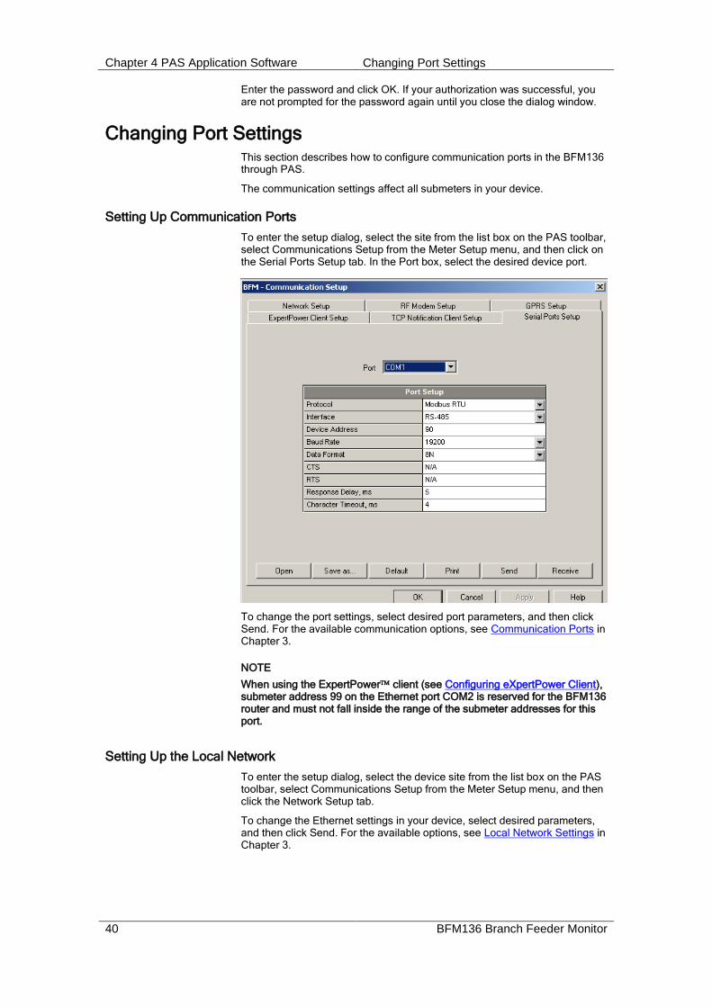
Setting Up Communication Ports
To enter the setup dialog, select the site from the list box on the PAS toolbar, select Communications Setup from the Meter Setup menu, and then click on the Serial Ports Setup tab. In the Port box, select the desired device port.
To change the port settings, select desired port parameters, and then click Send. For the available communication options, see Communication Ports in Chapter 3.
NOTE
When using the ExpertPower client (see Configuring eXpertPower Client), submeter address 99 on the Ethernet port COM2 is reserved for the BFM136 router and must not fall inside the range of the submeter addresses for this port.
Setting Up the Local Network
To enter the setup dialog, select the device site from the list box on the PAS toolbar, select Communications Setup from the Meter Setup menu, and then click the Network Setup tab.
To change the Ethernet settings in your device, select desired parameters, and then click Send. For the available options, see Local Network Settings in Chapter 3.

Chapter 4 PAS Application Software Changing Port Settings
BFM136 Branch Feeder Monitor 41
Configuring Wireless RF Connections
To enter the Setup dialog, select the site from the list box on the PAS toolbar, select Communications Setup from the Meter Setup menu, and then click on the RF Modem Setup tab.
The following table lists available RF modem options.
Label Options Default Description
MAC Net ID 0-255 0 MAC layer network ID
MAC Node ID 1-247 1 MAC layer node ID
Network Net ID 0-255 0 Network cluster ID
Network Node ID 1-247 1 Network layer node ID
Node Type RN+, RN-, RFD
RN+ Node router type
RF Channel 907 MHz,
910 MHz,
912 MHz,
915 MHz,
917 MHz,
920 MHz,
922 MHz
915 MHz RF channel frequency
RF Power 0-255 255 RF send power
NOTES:
1. Set the RF channel frequency and the MAC Network ID the same as you selected in the ETC2002 network router.
2. Set the Network Layer Net ID the same as the MAC Network ID.
Configuring eXpertPower Client
The BFM136 has an embedded eXpertPowerTM client that provides communications with the eXpertPowerTM server – the SATEC proprietary Internet services. Connections to the eXpertPowerTM server are handled on a periodic basis.

Chapter 4 PAS Application Software Changing Port Settings
42 BFM136 Branch Feeder Monitor
To enter the Setup dialog, select the site from the list box on the PAS toolbar, select Communication Setup from the Meter Setup menu, and then click the ExpertPower Client Setup tab.
The following table lists available options. Refer to your eXpertPower service provider for the correct eXpertPower settings.
Parameter Options Default Description
XPW Server IP Address 207.232.60.18
The IP address of the eXpertPower server
XPW Server Port 0-65535 5001 The TCP service port of the eXpertPower server
XPW Client Enabled NO, YES NO Enables operations of the eXpertPower client
Time to Next Session, min 1-99999
The time remaining to the next connection session
NOTES
1. If you do not use the eXpertPowerTM service, do not enable the eXpertPower client in your device.
2. Do not change the connection period setting. The eXpertPower server updates it automatically.

Chapter 4 PAS Application Software General Meter Setup
BFM136 Branch Feeder Monitor 43
General Meter Setup This section describes how to configure the BFM136 for your particular environment and application using PAS.
Basic Meter Setup
Before operating your meter, provide the device with basic information about your electrical network.
To enter the setup dialog, select the device site from the list box on the PAS toolbar, and then select General Setup from the Meter Setup menu.
The following table lists available device configuration options.
Parameter Options Default Description
Basic Configuration
PT Ratio 1.0-6500.0 1.0 The phase potential transformer’s primary to secondary ratio
Primary current 1-10000 A 50A The HACS primary current of the submeter’s; for information only.
Nominal frequency 50, 60 Hz 60Hz The nominal power frequency
Demand Setup
Block power demand period
1, 2, 5, 10, 15, 20, 30, 60 min
30 The length of the demand period for power demand calculations
The number of blocks in the sliding window
1-15 1 The number of block demand periods to be averaged for sliding window demands
Volt demand period 0-9000 sec 900 sec The length of the demand period for volt demand calculations
Ampere demand period
0-9000 sec 900 sec The length of the demand period for ampere demand calculations
Device Options
Power calculation mode
S=f(P, Q) (using reactive power),
Q=f(S, P) (using non-active power)
S=f(P, Q) The method used for calculating reactive and apparent powers (see “Power Calculation Modes” below)

Chapter 4 PAS Application Software General Meter Setup
44 BFM136 Branch Feeder Monitor
Parameter Options Default Description
Energy roll value, kWh
100000.0 kWh
1000000.0 kWh
10000000.0 kWh
100000000.0 kWh
100000000.0 The value at which energy counters roll over to zero
Energy LED pulse rate, Wh/pulse
0.01-100.00 5.40 Wh/pulse (one equivalent disk revolution)
LED pulse constant - the amount of accumulated energy (in secondary readings) giving one pulse via “Wh”.
Energy LED Test Disabled,
Wh Pulses,
varh Pulses
Disabled The type of accumulated energy giving pulses via “Wh” LED.
Energy LED Pulse source
SubMeter 1,
SubMeter 2,
…
SubMeter 40
SubMeter 1 The submeter uses as source of accumulated energy giving pulses via “Wh” LED.
Volts Scale, V 60-600 V 600 V The maximum voltage scale allowed, in secondary volts. See Data Scales in Appendix E
Power Calculation Modes
The power calculation mode option allows you to change the method for calculating reactive and apparent powers in presence of high harmonics. The options work as follows:
1. When the reactive power calculation mode is selected, active and reactive powers are measured directly and apparent power is calculated as:
22 QPS
This mode is recommended for electrical networks with low harmonic distortion, commonly with THD < 5% for volts, and THD < 10% for currents. In networks with high harmonics, the following method is preferable.
2. When the non-active power calculation mode is selected, active power is measured directly, apparent power is taken as product S = V x I, where V and I are the RMS volts and amps, and reactive power (called non-active power) is calculated as:
22 PSN
Channel Assignments
The Channel Assignments setup allows you to link the device current terminals to submeters so they can monitor them. Additionally, this setup allows you to specify the primary current rating of the current transformers connected to the device terminals. The number of the selected current inputs for a submeter specifies if it will be a single-, two-, or three-phase meter.
Always select your submeters (both metering and totalization) in a sequence without gaps so that your device does not occupy unnecessary network addresses.
To enter the setup dialog, select the device site from the list box on the PAS toolbar, select General Setup from the Meter Setup menu, and then click on the Channel Assignments tab.

Chapter 4 PAS Application Software General Meter Setup
BFM136 Branch Feeder Monitor 45
The following table lists available options.
Label Parameter Options Default Description
SubMeter Submeter number #1–#36 The submeter index
Phase L1 Phase L2 Phase L3
Phase current input terminal number
I1–I36, None
See
note1
Links a current input terminal to the corresponding submeter’s phase voltage input V1, V2 or V3
CT Primary, A HACS primary
current 2
1-10000 A 50 A Specifies the primary rating of the submeter current transformers
1 The device is pre-configured for twelve three-phase submeters as shown in the picture. 2 Specify the HACS ratings assuming a 200% device inputs overrange. The device inputs are preset for 100A current transformers with a 50A primary rating.
Transformer Correction
Transformer correction allows you to compensate ratio and phase angle inaccuracies of the user voltage transformers and SATEC current sensors (HACS) instrument.
To enter the setup dialog, select the device site from the list box1 on the PAS toolbar, and then select Transformer Correction from the Meter Setup menu.
If you use standard current transformers listed in the last table column, select a transformer type to preset the transformer ratio correction factor and phase angle error to their typical values.
1 - User CT option is not recommended, it doesn’t guaranty proper measurement - LEM and THI transformer type options are no more manufactured.
Chapter 4 PAS Application Software General Meter Setup
46 BFM136 Branch Feeder Monitor
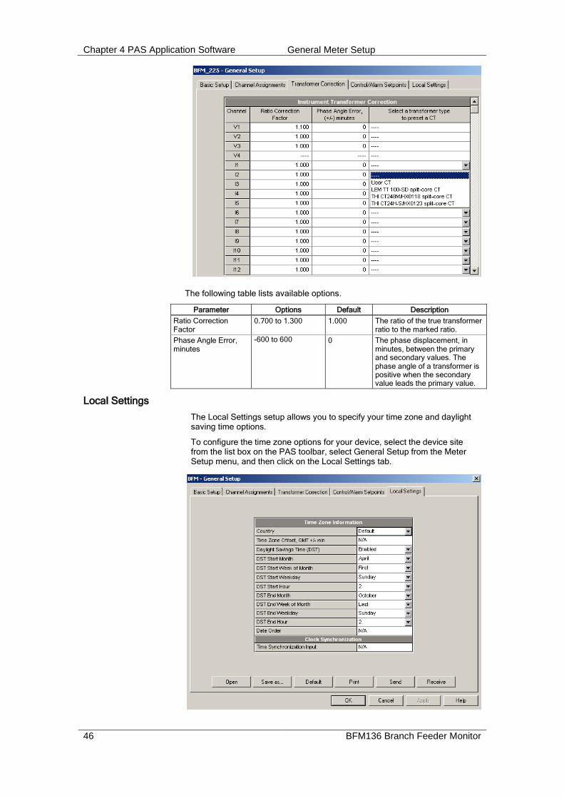
The following table lists available options.
Parameter Options Default Description
Ratio Correction Factor
0.700 to 1.300 1.000 The ratio of the true transformer ratio to the marked ratio.
Phase Angle Error, minutes
-600 to 600
0 The phase displacement, in
minutes, between the primary and secondary values. The phase angle of a transformer is positive when the secondary value leads the primary value.
Local Settings
The Local Settings setup allows you to specify your time zone and daylight saving time options.
To configure the time zone options for your device, select the device site from the list box on the PAS toolbar, select General Setup from the Meter Setup menu, and then click on the Local Settings tab.

Chapter 4 PAS Application Software General Meter Setup
BFM136 Branch Feeder Monitor 47
The available options are described in the following table:
Parameter Options Default Description
Country code Default, or country name
Default Defines a currency and calendar settings. The default setting stands for the U.S.A.
Daylight saving time option
Disabled
Enabled
Disabled When DST is disabled, the RTC will operate in standard time only. When enabled, the device will automatically update the time at 2:00 AM at the pre-defined DST switch dates.
DST start month
DST start week
DST start weekday
Month-week-weekday
Week = 1st, 2nd, 3rd, 4thor Last (last week of the month)
First Sunday in April
The date when Daylight Saving Time begins. The DST switch point is specified by the month, week of the month and weekday. By default, DST starts at 2:00 AM on the first Sunday in April of each year.
DST end month
DST end week
DST end weekday
Month-week-weekday
Week = 1st, 2nd, 3rd, 4thor Last (last week of the month)
Last Sunday in October
The date when Daylight Saving Time ends. The DST switch point is specified by the month, week of the month and weekday. By default, DST ends at 2:00 AM on the last Sunday in October of each year.
When the daylight saving time is enabled, the BFM136 automatically adjusts the device clock at 02.00 AM when daylight saving time begins/ends. The default daylight saving time change points are set for the U.S.A.
If the daylight saving time option is disabled, you need to manually adjust the device clock for daylight saving time.
Using Alarm/Control Setpoints
BFM136 has an embedded logical controller that runs different actions in response to user-defined internal and external events. Unlike a PLC, the BFM136 uses a simplified programming technique based on setpoints that allows the user to program a required action based on a measured analog value or on a time. The controller provides up to 4 setpoints for each submeter.
This setup allows configuring setpoints for each individual submeter. It can be read and changed via the corresponding submeter’s address.
To program the setpoints for a submeter, select General Setup from the Meter Setup menu, and then click on the Control/Alarm Setpoints tab.

Chapter 4 PAS Application Software Configuring Billing Energy and TOU Registers
48 BFM136 Branch Feeder Monitor
The following table describes the setpoint options.
Option Range Description
Trigger parameter
See Appendix D The trigger parameter that is used as an argument in the logical expression
Operate limit The threshold (in primary units) at which the conditional expression would be evaluated to true. Not applicable for time triggers.
Release limit The threshold (in primary units) at which the conditional expression would be evaluated to false. Defines the hysteresis for analog triggers. Not applicable for digital triggers.
Operate delay 0.1-999.9 sec The time delay before operation when the operate conditions are fulfilled
Release delay 0.1-999.9 sec The time delay before release when the release conditions are fulfilled
Action See Appendix D The action performed when the setpoint expression is evaluated to true (the setpoint is in operated state)
Using Numeric Triggers
For numeric (analog) triggers, a setpoint allows you to specify two thresholds for each trigger to provide hysteresis (dead band) for setpoint operations. The operate limit defines the operating threshold, and the second release limit defines the release threshold for the trigger. If you do not want to use hysteresis for the trigger, set the release limit to the same as the operate limit.
Using Time Triggers
If you want the setpoint actions to be synchronized with the clock, for example, to provide recording interval data, use the minute time interval trigger that generates periodic events synchronized with the device clock.
Delaying Setpoint Operations
Two optional delays can be added to each setpoint to extend monitoring a setpoint trigger for a longer time before making a decision on whether the expected event occurred or not. When a delay is specified, the logical controller will change the setpoint status only if all conditions are asserted for a period at least as long as the delay time.
Using Setpoint Events
When a setpoint status changes, i.e., a setpoint event is either asserted or de-asserted, the following happens in your device:
1. The new setpoint status is logged to the setpoint status register that can be monitored via communications from the user application software in order to give a real-time indication on the expected event.
2. The operated setpoint status is latched to the setpoint alarm register accessible through communications. The register holds the last setpoint alarm status until it is explicitly cleared via communications.
Recording Setpoint Events
Time-tagged setpoint events can be recorded to the submeter event log if you select it as the setpoint action. The Event recorder logs any setpoint transition event: both when the setpoint is operated, and when it is released.
Configuring Billing Energy and TOU Registers The BFM136 provides four total/summary energy and six parallel tariff energy and maximum demand registers for each individual submeter. The registers can be linked to any internal energy source or to another submeter.

Chapter 4 PAS Application Software Configuring Billing Energy and TOU Registers
BFM136 Branch Feeder Monitor 49
The meter tariff structure supports six different tariffs using an arbitrary tariff schedule. A total of four types of days and four seasons are supported with up to eight tariff changes per day.
The meter can provide automatic daily profile recording for total and tariff energy and maximum demand registers. The device memory is sufficient to store daily profile data for 120 days.
By default, the first billing register in your meter is linked to the kWh IMPORT accumulator, and the daily profile recording is enabled for the kWh register. Other billing registers are not operational. To activate the remaining registers or to change the profile for the first billing register:
1. Link the Summary/TOU registers to the respective energy sources, and then configure the options for these registers like whether the only totalization or both total and tariff registers would be used, and whether daily profiling should be enabled for the energy usage and maximum demand registers.
2. Configure the daily tariff schedule for all types of days and seasons using the TOU daily profiles.
3. Configure the season tariff schedule using the TOU calendar.
Setting up Total and Tariff Registers
To configure the device total (summary) and TOU registers, select Energy/TOU from the Meter Setup menu.
The available options are shown in the following table:
Parameter Options Default Description
Billing/TOU Registers
TOU Unchecked
Checked
Unchecked Links tariff registers to the selected energy source
Use Profl Unchecked
Checked
Unchecked Enables automatic daily profiling for energy usage registers (both total and tariff registers if TOU is enabled)
Dmd Profl Unchecked
Checked
Unchecked Enables automatic daily profiling for maximum demand registers (both total and tariff registers if TOU is enabled)
Sum Profl Unchecked
Checked
Unchecked Enables daily profiling for summary registers (total of all tariffs). Automatically set when profiling is enabled.
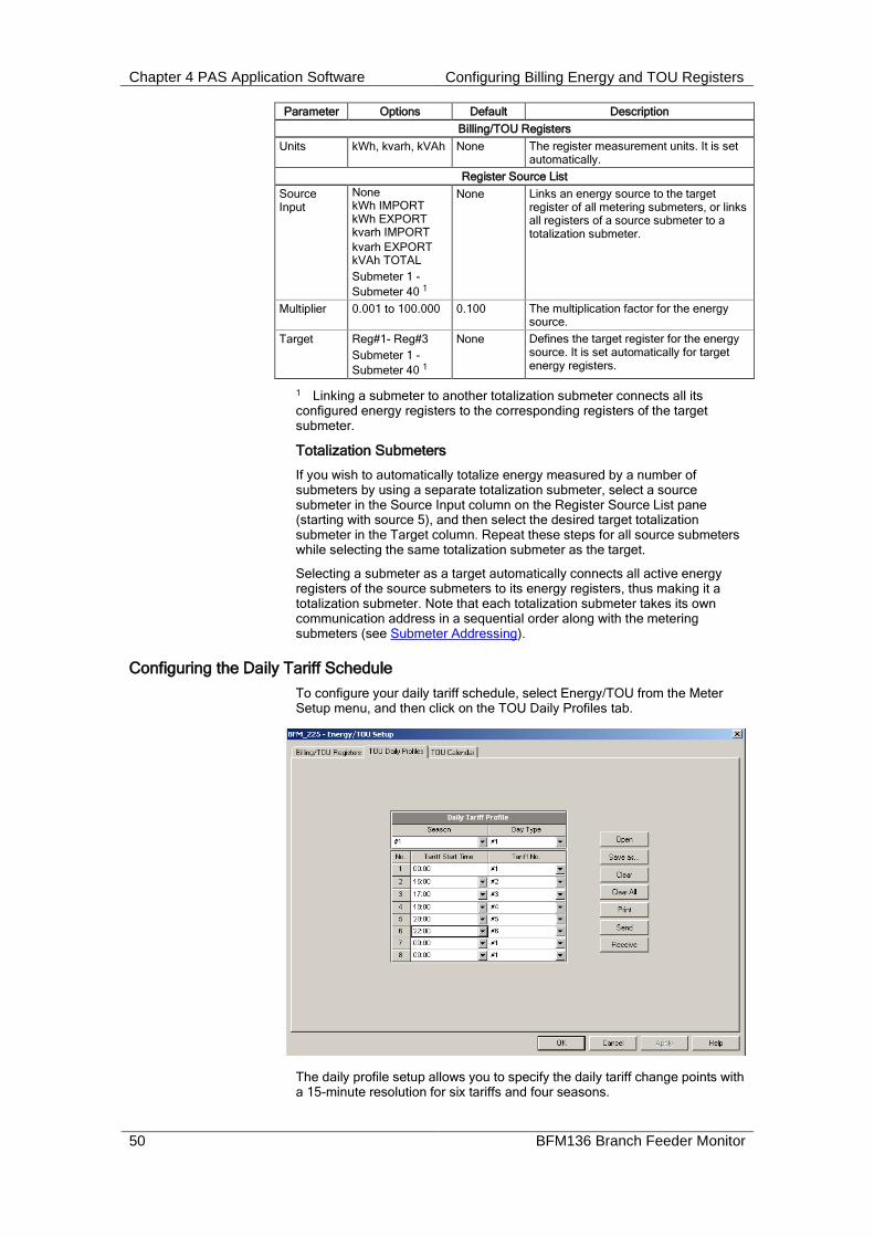
Chapter 4 PAS Application Software Configuring Billing Energy and TOU Registers
50 BFM136 Branch Feeder Monitor
Parameter Options Default Description
Billing/TOU Registers
Units kWh, kvarh, kVAh None The register measurement units. It is set automatically.
Register Source List
Source Input
None kWh IMPORT kWh EXPORT kvarh IMPORT
kvarh EXPORT kVAh TOTAL
Submeter 1 -
Submeter 40 1
None Links an energy source to the target register of all metering submeters, or links all registers of a source submeter to a totalization submeter.
Multiplier 0.001 to 100.000 0.100 The multiplication factor for the energy source.
Target Reg#1- Reg#3
Submeter 1 -
Submeter 40 1
None Defines the target register for the energy source. It is set automatically for target energy registers.
1 Linking a submeter to another totalization submeter connects all its configured energy registers to the corresponding registers of the target submeter.
Totalization Submeters
If you wish to automatically totalize energy measured by a number of submeters by using a separate totalization submeter, select a source submeter in the Source Input column on the Register Source List pane (starting with source 5), and then select the desired target totalization submeter in the Target column. Repeat these steps for all source submeters while selecting the same totalization submeter as the target.
Selecting a submeter as a target automatically connects all active energy registers of the source submeters to its energy registers, thus making it a totalization submeter. Note that each totalization submeter takes its own communication address in a sequential order along with the metering submeters (see Submeter Addressing).
Configuring the Daily Tariff Schedule
To configure your daily tariff schedule, select Energy/TOU from the Meter Setup menu, and then click on the TOU Daily Profiles tab.
The daily profile setup allows you to specify the daily tariff change points with a 15-minute resolution for six tariffs and four seasons.

Chapter 4 PAS Application Software Configuring Billing Energy and TOU Registers
BFM136 Branch Feeder Monitor 51
To configure your daily profiles:
1. Select the desired season and day type.
2. Select the start time for each tariff change point and the corresponding active tariff number.
3. Repeat the setup for all active profiles.
The first tariff change point is fixed at 00:00 hours, and the last tariff change you specified will be in use until 00:00 hours on the next day.
The energy daily profile log will be automatically configured for the number of active tariffs you defined in the BFM136 TOU daily profile.
Configuring the Season Tariff Schedule
To configure your season tariff schedule, select Energy/TOU from the Meter Setup menu, and then click on the TOU Calendar tab.
The TOU calendar allows you to configure any tariff schedule based on any possible utility regulation. The calendar itself has 32 entries that allow you to specify profiles for working days and holidays through all seasons in any order that is convenient for you, based on simple intuitive rules. There are no limitations on how to define your schedule. The BFM136 is able to automatically recognize your settings and to select a proper daily tariff schedule for any day within a year.
1. The following picture gives you an example of a single-season tariff schedule configured for weekends and the designated US holidays.
To configure your season tariff schedule:
1. In the “Season” box, select the season, and in the “Day Type” box, select a day type for this calendar entry.
2. Select the time interval when this daily tariff schedule will be effective based on the start and the end weekdays and, for a multi-season schedule, on the start and the end month for the selected season. It

Chapter 4 PAS Application Software Configuring Data Recorders
52 BFM136 Branch Feeder Monitor
does not matter which order of weekdays or months you selected: the BFM136 recognizes the correct order.
3. For exception days such as holidays, select a specific day either by specifying a day and month, or by selecting a month, a week and a weekday within the month.
Configuring Data Recorders The BFM136 provides a separate Data recorder for each metering submeter. The recorder is triggered via a setpoint periodically for recording interval data (see Using Alarm/Control Setpoints).
The device memory is factory partitioned to allow recording one data log file per submeter (Data Log #1) with a maximum of 5000 records per file. A data log file is organized as a wrap-around file that needs not to be cleared explicitly though it can be done via PAS (see Clearing Maximum Demands and Log Files). When a file is filled up, the new records overwrite oldest records, so a file always keeps the 5000 latest records.
The Data recorder is programmable to record up to six data parameters per record. The list of parameters is configured individually for each submeter and can be read and changed via the corresponding submeter’s address.
To configure the data log for a submeter:
1. Select Log Setup from the Meter Setup menu.
2. Configure the list of parameters to be recorded in the data log file. See Parameters for Data Monitoring and Logging in Appendix C for a list of the available parameters.
3. Add the name for your data log file in the Name box. It will appear in the data log reports.
4. Save your new setup to the device database, and send it to the meter.
5. Configure a setpoint for periodic triggering the Data recorder using the MINUTE INTERVAL trigger (see Using Alarm/Control Setpoints).
Remote Device Control This section describes some online operations on the BFM136 you can perform through PAS. To access device control options you should have your device online.

Chapter 4 PAS Application Software Remote Device Control
BFM136 Branch Feeder Monitor 53
Viewing and Clearing Device Diagnostics
To view or clear the device diagnostics status, check the On-line button on the PAS toolbar and select Device Control from the Monitor menu.
Refer to Device Diagnostic Codes in Appendix F for the list of diagnostic codes and their meanings. See Device Diagnostics in Chapter 2 for more information on the BFM136 built-in diagnostics.
Click on the Clear button to clear the device diagnostics. You must be connected to the BFM136 using the device base address to be able to clear the diagnostics status.
Updating the Clock
To update the RTC clock in your device, select a site with base device address from the list box on the toolbar, check the On-line button on the toolbar, and then select RTC from the Monitor menu.
The RTC dialog box displays the current PC time and the time in your device. To synchronize the device clock with the PC clock, click Set.
Clearing Maximum Demands and Log Files
PAS allows you to remotely clear maximum demands and log files individually in each submeter.
To open the dialog box, select a device site from the list box on the toolbar, check the On-line button, and then select Reset from the Monitor menu.
To reset the desired registers or to clear a file:

Chapter 4 PAS Application Software Administration
54 BFM136 Branch Feeder Monitor
1. Click on the corresponding button, and then confirm your command.
2. If a target has more than one component, you are allowed to select components to reset.
3. Check the corresponding boxes and click OK.
Administration PAS allows you to remotely change the password or network security in your BFM136 . Use the device base address to access your device.
To change the password, select a device site from the list box on the PAS toolbar, check the On-line button, click Administration from the monitor menu, and then select Change Password.
To change the password, type in a new 8-digit password, repeat the password in the Confirm box, and then click Send.
Upgrading Device Firmware Your meter has upgradeable firmware. If you need to upgrade your device, you can download a new firmware file to the meter through PAS.
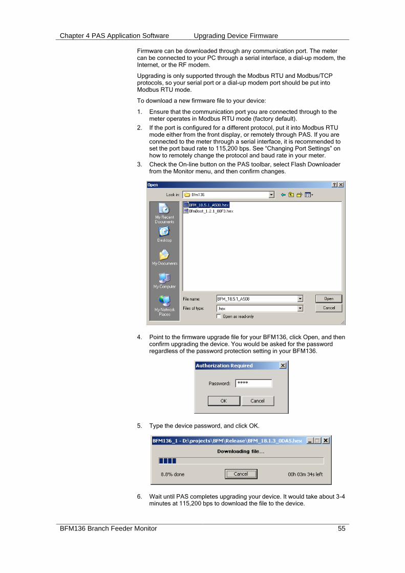
Chapter 4 PAS Application Software Upgrading Device Firmware
BFM136 Branch Feeder Monitor 55
Firmware can be downloaded through any communication port. The meter can be connected to your PC through a serial interface, a dial-up modem, the Internet, or the RF modem.
Upgrading is only supported through the Modbus RTU and Modbus/TCP protocols, so your serial port or a dial-up modem port should be put into Modbus RTU mode.
To download a new firmware file to your device:
1. Ensure that the communication port you are connected through to the meter operates in Modbus RTU mode (factory default).
2. If the port is configured for a different protocol, put it into Modbus RTU mode either from the front display, or remotely through PAS. If you are connected to the meter through a serial interface, it is recommended to set the port baud rate to 115,200 bps. See “Changing Port Settings” on how to remotely change the protocol and baud rate in your meter.
3. Check the On-line button on the PAS toolbar, select Flash Downloader from the Monitor menu, and then confirm changes.
4. Point to the firmware upgrade file for your BFM136, click Open, and then confirm upgrading the device. You would be asked for the password regardless of the password protection setting in your BFM136.
5. Type the device password, and click OK.
6. Wait until PAS completes upgrading your device. It would take about 3-4 minutes at 115,200 bps to download the file to the device.

Chapter 4 PAS Application Software Upgrading Device Firmware
56 BFM136 Branch Feeder Monitor
7. After upgrading firmware is completed, the device restarts. If the meter is connected to your PC through the modem, communications can be temporarily lost and you may need to wait until PAS restores a connection with your device.

Chapter 4 PAS Application Software Data Monitoring
BFM136 Branch Feeder Monitor 57
Data Monitoring
Viewing Real-Time Data
Real-time data can be continuously retrieved from the BFM136 submeters, updated on the screen at the rate you defined in the Instrument Setup, and recorded to a file. You can view acquired data in a tabular or in a graphical form as a data trend.
For information on the real-time data monitoring and recording options, see the PAS Getting Started Guide.
To get data from all submeters in a single window, click on the Multi-meter View button on the local toolbar.
Any energy and maximum demand registers in the BFM136 submeters can be read and recorded to files through the PAS Data Monitor.
Retrieving Log Files
Using PAS, you can retrieve the event and data log files from the BFM136 submeters and save them to files on your PC in the MS Access database format.
Historical data is uploaded on demand any time you need it, or periodically through the Upload Scheduler that retrieves data automatically on a predefined schedule, for example, daily, weekly or monthly. If you do not change the destination database location, new data is added to the same database so you can have long-term data trends and energy profiles in one database regardless of the upload schedule you selected.
For information on uploading files and configuring the Upload Scheduler for the BFM136 submeters, see the PAS Getting Started Guide.
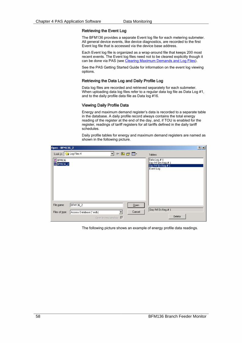
Chapter 4 PAS Application Software Data Monitoring
58 BFM136 Branch Feeder Monitor
Retrieving the Event Log
The BFM136 provides a separate Event log file for each metering submeter. All general device events, like device diagnostics, are recorded to the first Event log file that is accessed via the device base address.
Each Event log file is organized as a wrap-around file that keeps 200 most recent events. The Event log files need not to be cleared explicitly though it can be done via PAS (see Clearing Maximum Demands and Log Files).
See the PAS Getting Started Guide for information on the event log viewing options.
Retrieving the Data Log and Daily Profile Log
Data log files are recorded and retrieved separately for each submeter. When uploading data log files refer to a regular data log file as Data Log #1, and to the daily profile data file as Data log #16.
Viewing Daily Profile Data
Energy and maximum demand register’s data is recorded to a separate table in the database. A daily profile record always contains the total energy reading of the register at the end of the day, and, if TOU is enabled for the register, readings of tariff registers for all tariffs defined in the daily tariff schedules.
Daily profile tables for energy and maximum demand registers are named as shown in the following picture.
The following picture shows an example of energy profile data readings.
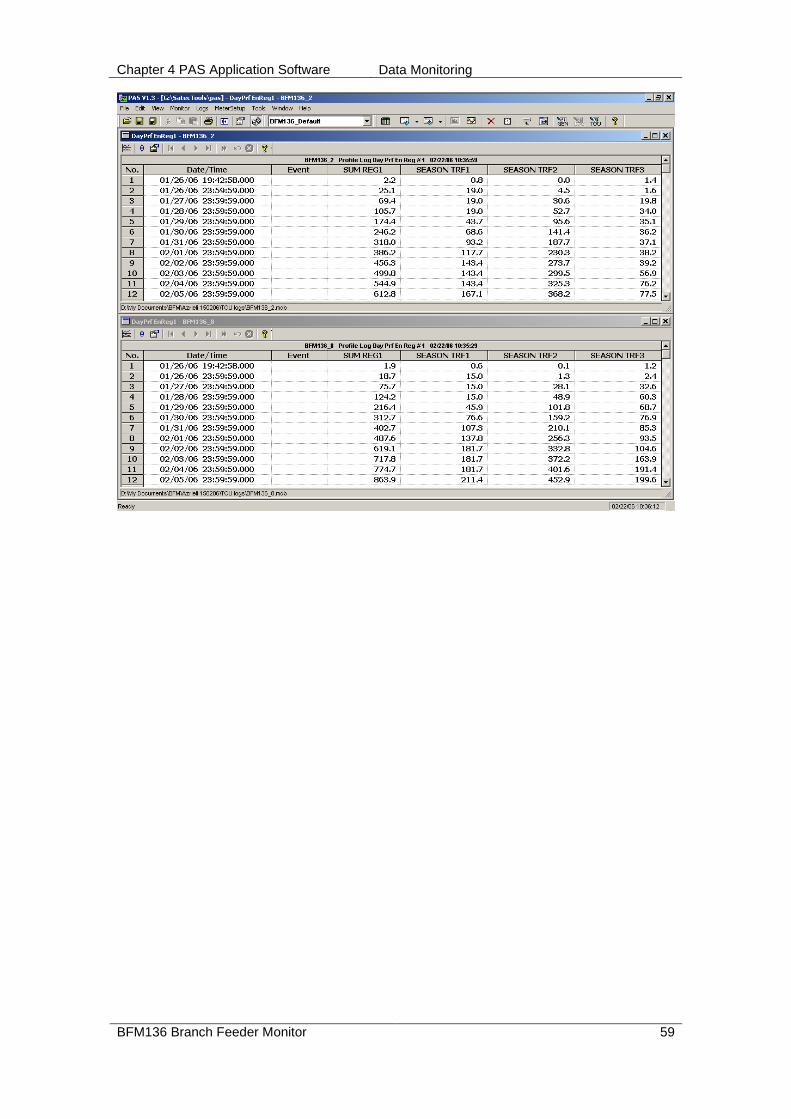
Chapter 4 PAS Application Software Data Monitoring
BFM136 Branch Feeder Monitor 59
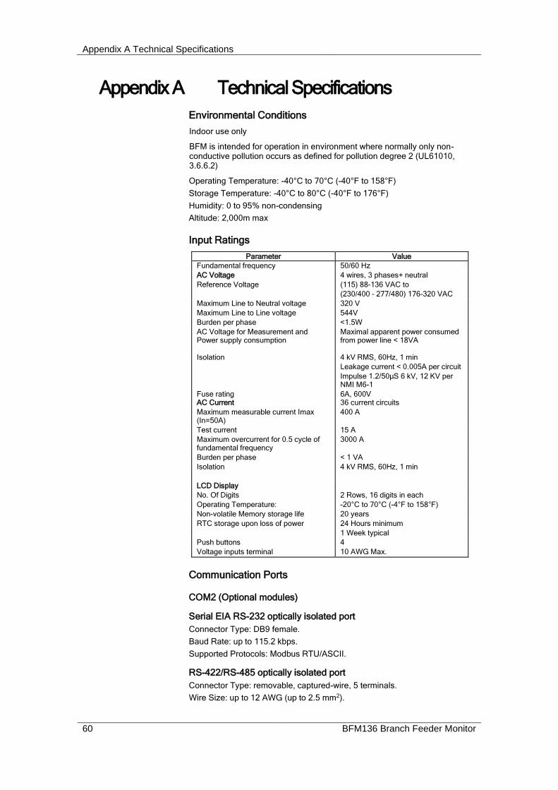
Appendix A Technical Specifications
60 BFM136 Branch Feeder Monitor
Appendix A Technical Specifications
Environmental Conditions
Indoor use only
BFM is intended for operation in environment where normally only non-conductive pollution occurs as defined for pollution degree 2 (UL61010, 3.6.6.2)
Operating Temperature: -40°C to 70°C (-40°F to 158°F)
Storage Temperature: -40°C to 80°C (-40°F to 176°F)
Humidity: 0 to 95% non-condensing
Altitude: 2,000m max
Input Ratings
Parameter Value
Fundamental frequency 50/60 Hz
AC Voltage 4 wires, 3 phases+ neutral
Reference Voltage (115) 88-136 VAC to
(230/400 – 277/480) 176-320 VAC
Maximum Line to Neutral voltage 320 V
Maximum Line to Line voltage 544V
Burden per phase <1.5W
AC Voltage for Measurement and Power supply consumption
Maximal apparent power consumed from power line < 18VA
Isolation 4 kV RMS, 60Hz, 1 min
Leakage current < 0.005A per circuit
Impulse 1.2/50μS 6 kV, 12 KV per NMI M6-1
Fuse rating 6A, 600V AC Current 36 current circuits
Maximum measurable current Imax (In=50A)
400 A
Test current 15 A
Maximum overcurrent for 0.5 cycle of fundamental frequency
3000 A
Burden per phase < 1 VA
Isolation 4 kV RMS, 60Hz, 1 min
LCD Display
No. Of Digits 2 Rows, 16 digits in each
Operating Temperature: -20°C to 70°C (-4°F to 158°F)
Non-volatile Memory storage life 20 years
RTC storage upon loss of power 24 Hours minimum
1 Week typical
Push buttons 4
Voltage inputs terminal 10 AWG Max.
Communication Ports
COM2 (Optional modules)
Serial EIA RS-232 optically isolated port
Connector Type: DB9 female.
Baud Rate: up to 115.2 kbps.
Supported Protocols: Modbus RTU/ASCII.
RS-422/RS-485 optically isolated port
Connector Type: removable, captured-wire, 5 terminals.
Wire Size: up to 12 AWG (up to 2.5 mm2).
Appendix A Technical Specifications
BFM136 Branch Feeder Monitor 61
Baud Rate: up to 115.2 kbps.
Supported Protocols: Modbus RTU/ASCII.
Ethernet Port
Transformer-isolated 10/100BaseT Ethernet port.
Connector Type: RJ45 modular.
Supported Protocols: Modbus TCP (Port 502).
Number of simultaneous connections (sockets): 2.
Dial-up Modem Port
Transformer-isolated internal 56K modem.
Connector Type: RJ11.
Supported Protocols: Modbus RTU/ASCII.
Real-time Clock
Accuracy: typical error 1 minute per month @ 25C
Standards Compliance
EN50081-2 Generic Emission Standard - Industrial Environment
EN50082-2 Generic Immunity Standard - Industrial Environment
UL61010-1
EN55022: 1994 Class B
EN61000-4-2
ENV50140: 1983
ENV50204: 1995 (900MHz)
ENV50141: 1993
EN61000-4-4:1995
EN61000-4-8: 1993
NMI M6-1 IEC/AZ 62053-22 class 0.5S
ANSI C12.1, C12.20 accuracy class 0.5
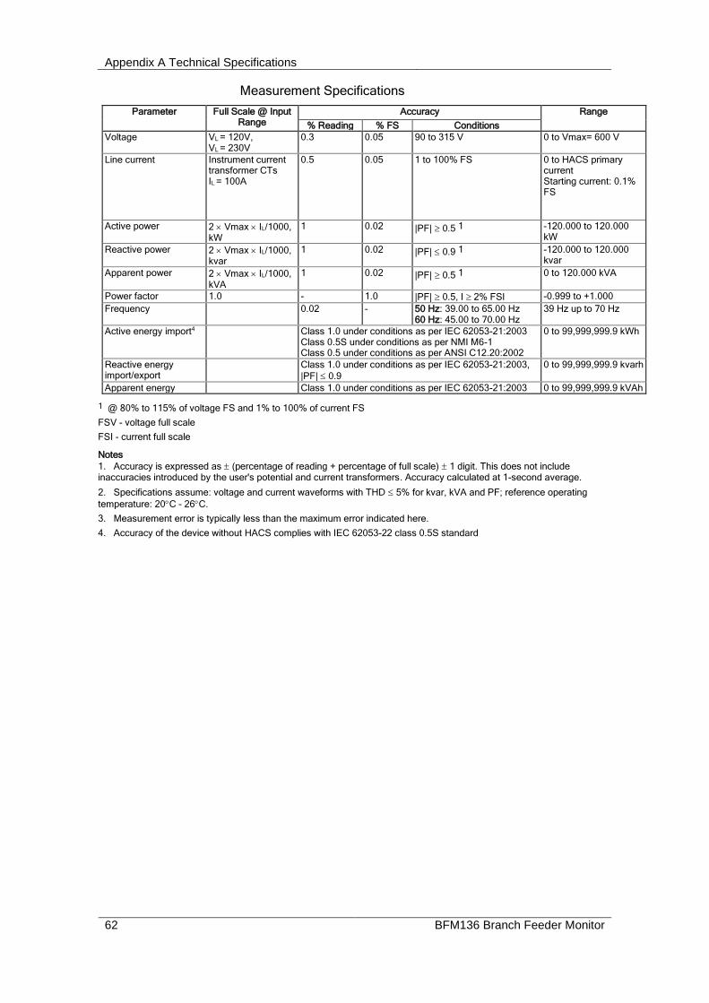
Appendix A Technical Specifications
62 BFM136 Branch Feeder Monitor
Measurement Specifications
Parameter Full Scale @ Input Range
Accuracy Range
% Reading % FS Conditions
Voltage VL = 120V, VL = 230V
0.3 0.05 90 to 315 V 0 to Vmax= 600 V
Line current
Instrument current transformer CTs IL = 100A
0.5 0.05 1 to 100% FS 0 to HACS primary current Starting current: 0.1% FS
Active power 2 Vmax IL/1000, kW
1 0.02 |PF| 0.5 1 -120.000 to 120.000 kW
Reactive power 2 Vmax IL/1000, kvar
1 0.02 |PF| 0.9 1 -120.000 to 120.000 kvar
Apparent power 2 Vmax IL/1000, kVA
1 0.02 |PF| 0.5 1 0 to 120.000 kVA
Power factor 1.0 - 1.0 |PF| 0.5, I 2% FSI -0.999 to +1.000
Frequency 0.02 - 50 Hz: 39.00 to 65.00 Hz 60 Hz: 45.00 to 70.00 Hz
39 Hz up to 70 Hz
Active energy import4 Class 1.0 under conditions as per IEC 62053-21:2003 Class 0.5S under conditions as per NMI M6-1 Class 0.5 under conditions as per ANSI C12.20:2002
0 to 99,999,999.9 kWh
Reactive energy import/export
Class 1.0 under conditions as per IEC 62053-21:2003,
|PF| 0.9
0 to 99,999,999.9 kvarh
Apparent energy Class 1.0 under conditions as per IEC 62053-21:2003 0 to 99,999,999.9 kVAh
1 @ 80% to 115% of voltage FS and 1% to 100% of current FS
FSV - voltage full scale
FSI - current full scale
Notes
1. Accuracy is expressed as (percentage of reading + percentage of full scale) 1 digit. This does not include inaccuracies introduced by the user's potential and current transformers. Accuracy calculated at 1-second average.
2. Specifications assume: voltage and current waveforms with THD 5% for kvar, kVA and PF; reference operating
temperature: 20C - 26C.
3. Measurement error is typically less than the maximum error indicated here.
4. Accuracy of the device without HACS complies with IEC 62053-22 class 0.5S standard

Appendix B HACS Connection Template
BFM136 Branch Feeder Monitor 63
Appendix B HACS Connection Template Use the following table to memorize your input assignments and wiring connections for sub-consumers.
Sub-consumer Input#1 Wire Color Cable# Phase
1
2
3
4
5
6
7
8
9
10
11
12
13
14
15
16
17
18
19
20
21
22
23
24
25
26
27
28
29
30
31
32
33
34
35
36
1 #1 through #36

Appendix C Parameters for Data Monitoring and Logging
64 BFM136 Branch Feeder Monitor
Appendix C Parameters for Data Monitoring and Logging
The following table lists parameters measured by the meter that are available for data logging and monitoring through communications. The left column shows data abbreviations used in PAS. Parameter groups are highlighted in bold.
Designation Description
NONE None (stub, read as zero)
RT PHASE 1-Cycle Phase Values
V1 V1
V2 V2
V3 V3
I1 I1 Current
I2 I2 Current
I3 I3 Current
kW L1 kW L1
kW L2 kW L2
kW L3 kW L3
kvar L1 kvar L1
kvar L2 kvar L2
kvar L3 kvar L3
kVA L1 kVA L1
kVA L2 kVA L2
kVA L3 kVA L3
PF L1 Power factor L1
PF L2 Power factor L2
PF L3 Power factor L3
V12 V12 Voltage
V23 V23 Voltage
V31 V31 Voltage
RT TOTAL 1-Cycle Total Values
kW Total kW
kvar Total kvar
kVA Total kVA
PF Total PF
PF LAG Total PF lag
PF LEAD Total PF lead
kW IMP Total kW import
kW EXP Total kW export
kvar IMP Total kvar import
kvar EXP Total kvar export
RT AUX 1-Cycle Auxiliary Values
In In (neutral) Current
FREQ Frequency
AVR PHASE 1-Second Phase Values 1
V1 V1 Voltage
V2 V2 Voltage
V3 V3 Voltage
I1 I1 Current
I2 I2 Current
I3 I3 Current
kW L1 kW L1
kW L2 kW L2
kW L3 kW L3
kvar L1 kvar L1
kvar L2 kvar L2
kvar L3 kvar L3
kVA L1 kVA L1
kVA L2 kVA L2
kVA L3 kVA L3
PF L1 Power factor L1
PF L2 Power factor L2
PF L3 Power factor L3
V12 V12 Voltage

Appendix C Parameters for Data Monitoring and Logging
BFM136 Branch Feeder Monitor 65
Designation Description
V23 V23 Voltage
V31 V31 Voltage
AVR TOTAL 1-Second Total Values 1
kW Total kW
kvar Total kvar
kVA Total kVA
PF Total PF
PF LAG Total PF lag
PF LEAD Total PF lead
kW IMP Total kW import
kW EXP Total kW export
kvar IMP Total kvar import
kvar EXP Total kvar export
AVR AUX 1-Second Auxiliary Values 1
In In (neutral) Current
FREQ Frequency
DEMANDS Present Demands 1
V1 DMD V1 Volt demand
V2 DMD V2 Volt demand
V3 DMD V3 Volt demand
I1 DMD I1 Ampere demand
I2 DMD I2 Ampere demand
I3 DMD I3 Ampere demand
kW IMP SD kW import sliding window demand
kW EXP SD kW export sliding window demand
kvar IMP SD kvar import sliding window demand
kvar EXP SD kvar export sliding window demand
kVA SD kVA sliding window demand
kW IMP ACC DMD kW import accumulated demand
kW EXP ACC DMD kW export accumulated demand
kvar IMP ACC DMD kvar import accumulated demand
kvar EXP ACC DMD kvar export accumulated demand
kVA ACC DMD kVA accumulated demand
kW IMP PRD DMD kW import predicted sliding window demand
kW EXP PRD DMD kW export predicted sliding window demand
kvar IMP PRD DMD kvar import predicted sliding window demand
kvar EXP PRD DMD kvar export predicted sliding window demand
kVA PRD DMD kVA predicted sliding window demand
SUMM ACC DMD Summary (TOU Total) Accumulated Demands
SUM REG1 ACC DMD Summary register #1 demand
SUM REG2 ACC DMD Summary register #2 demand
SUM REG3 ACC DMD Summary register #3 demand
SUM REG4 ACC DMD Summary register #4 demand
SUMM SW DMD Summary (TOU Total) Sliding Demands 1
SUM REG1 SW DMD Summary register #1 demand
SUM REG2 SW DMD Summary register #2 demand
SUM REG3 SW DMD Summary register #3 demand
SUM REG4 SW DMD Summary register #4 demand
ENERGY Total Energy 1
kWh IMPORT kWh import
kvarh IMPORT kvarh import
kWh EXPORT kWh export
kvarh EXPORT kvarh export
kVAh TOTAL kVAh total
SUMMARY REGS Summary (TOU Total) Energy Registers 1
SUM REG1 Summary energy register #1
SUM REG2 Summary energy register #2
SUM REG3 Summary energy register #3
SUM REG4 Summary energy register #4
MAX DMD Maximum Demands
V1 DMD MAX V1 Maximum volt demand
V2 DMD MAX V2 Maximum volt demand
V3 DMD MAX V3 Maximum volt demand
I1 DMD MAX I1 Maximum ampere demand
I2 DMD MAX I2 Maximum ampere demand
I3 DMD MAX I3 Maximum ampere demand
kW IMP SD MAX Maximum kW import sliding window demand
kW EXP SD MAX Maximum kvar import sliding window demand

Appendix C Parameters for Data Monitoring and Logging
66 BFM136 Branch Feeder Monitor
Designation Description
kVA SD MAX Maximum kVA sliding window demand
MAX SUMMARY DMD Maximum Summary (TOU Total) Demands
SUM REG1 DMD MAX Summary register #1 maximum demand
SUM REG2 DMD MAX Summary register #2 maximum demand
SUM REG3 DMD MAX Summary register #3 maximum demand
SUM REG4 DMD MAX Summary register #4 maximum demand
TOU PRMS TOU Parameters
ACTIVE TARIFF Active TOU tariff
ACTIVE PROFILE Active TOU profile
TOU REG1 TOU Energy Register #1 1
TOU REG1 TRF1 Tariff #1 register
TOU REG1 TRF2 Tariff #2 register
TOU REG1 TRF3 Tariff #3 register
TOU REG1 TRF4 Tariff #4 register
TOU REG1 TRF5 Tariff #5 register
TOU REG1 TRF6 Tariff #6 register
TOU REG2 TOU Energy Register #2 1
TOU REG2 TRF1 Tariff #1 register
TOU REG2 TRF2 Tariff #2 register
TOU REG2 TRF3 Tariff #3 register
TOU REG2 TRF4 Tariff #4 register
TOU REG2 TRF5 Tariff #5 register
TOU REG2 TRF6 Tariff #6 register
TOU REG3 TOU Energy Register #3 1
TOU REG3 TRF1 Tariff #1 register
TOU REG3 TRF2 Tariff #2 register
TOU REG3 TRF3 Tariff #3 register
TOU REG3 TRF4 Tariff #4 register
TOU REG3 TRF5 Tariff #5 register
TOU REG3 TRF6 Tariff #6 register
TOU REG4 TOU Energy Register #4 1
TOU REG4 TRF1 Tariff #1 register
TOU REG4 TRF2 Tariff #2 register
TOU REG4 TRF3 Tariff #3 register
TOU REG4 TRF4 Tariff #4 register
TOU REG4 TRF5 Tariff #5 register
TOU REG4 TRF6 Tariff #6 register
TOU MAX DMD REG1 TOU Maximum Demand Register #1 1
DMD1 TRF1 MAX Tariff #1 register
DMD1 TRF2 MAX Tariff #2 register
DMD1 TRF3 MAX Tariff #3 register
DMD1 TRF4 MAX Tariff #4 register
DMD1 TRF5 MAX Tariff #5 register
DMD1 TRF6 MAX Tariff #6 register
TOU MAX DMD REG2 TOU Maximum Demand Register #2 1
DMD2 TRF1 MAX Tariff #1 register
DMD2 TRF2 MAX Tariff #2 register
DMD2 TRF3 MAX Tariff #3 register
DMD2 TRF4 MAX Tariff #4 register
DMD2 TRF5 MAX Tariff #5 register
DMD2 TRF6 MAX Tariff #6 register
TOU MAX DMD REG3 TOU Maximum Demand Register #3 1
DMD3 TRF1 MAX Tariff #1 register
DMD3 TRF2 MAX Tariff #2 register
DMD3 TRF3 MAX Tariff #3 register
DMD3 TRF4 MAX Tariff #4 register
DMD3 TRF5 MAX Tariff #5 register
DMD3 TRF6 MAX Tariff #6 register
TOU MAX DMD REG4 TOU Maximum Demand Register #4 1
DMD4 TRF1 MAX Tariff #1 register
DMD4 TRF2 MAX Tariff #2 register
DMD4 TRF3 MAX Tariff #3 register
DMD4 TRF4 MAX Tariff #4 register
DMD4 TRF5 MAX Tariff #5 register

Appendix C Parameters for Data Monitoring and Logging
BFM136 Branch Feeder Monitor 67
Designation Description
DMD4 TRF6 MAX Tariff #6 register
1 Available for data logging.
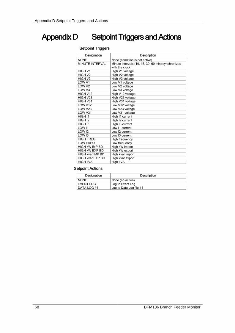
Appendix D Setpoint Triggers and Actions
68 BFM136 Branch Feeder Monitor
Appendix D Setpoint Triggers and Actions
Setpoint Triggers
Designation Description
NONE None (condition is not active)
MINUTE INTERVAL Minute intervals (10, 15, 30, 60 min) synchronized with the clock
HIGH V1 High V1 voltage
HIGH V2 High V2 voltage
HIGH V3 High V3 voltage
LOW V1 Low V1 voltage
LOW V2 Low V2 voltage
LOW V3 Low V3 voltage
HIGH V12 High V12 voltage
HIGH V23 High V23 voltage
HIGH V31 High V31 voltage
LOW V12 Low V12 voltage
LOW V23 Low V23 voltage
LOW V31 Low V31 voltage
HIGH I1 High I1 current
HIGH I2 High I2 current
HIGH I3 High I3 current
LOW I1 Low I1 current
LOW I2 Low I2 current
LOW I3 Low I3 current
HIGH FREQ High frequency
LOW FREQ Low frequency
HIGH kW IMP BD High kW import
HIGH kW EXP BD High kW export
HIGH kvar IMP BD High kvar import
HIGH kvar EXP BD High kvar export
HIGH kVA High kVA
Setpoint Actions
Designation Description
NONE None (no action)
EVENT LOG Log to Event Log
DATA LOG #1 Log to Data Log file #1

Appendix E Data Scales
BFM136 Branch Feeder Monitor 69
Appendix E Data Scales The maximum values for volts, amps and power in the BFM136 setup and in communications are limited by the voltage and current scale settings. See Basic Meter Setup in Chapter 4 on how to change the voltage scale in your meter.
The following table defines the meter data scales.
Scale Range Notes
Maximum voltage (V max) Voltage scale PT Ratio, V The default voltage scale is 600V
Maximum current (I max) HACS Primary current 2, A The default HACS primary current is 50A
Maximum power 1 V max I max 2, W
1 Maximum power is rounded to whole kilowatts. With PT=1.0, it is limited to 9,999,000 W.

Appendix F Device Diagnostic Codes
70 BFM136 Branch Feeder Monitor
Appendix F Device Diagnostic Codes
Diagnostic Code
Startup Display Message
Description Reason
2 RAM/Data Error Memory/Data error Hardware failure
3 WDT Reset Hardware watchdog reset Hardware failure
4 Sampling Fault Sampling fault Hardware failure
5 CPU Exception CPU exception Hardware failure
6 Run-Time Error Run-time software error Hardware failure
7 Software Exception Software watchdog timeout Hardware failure
8 Power Up Power Down/Up Loss of power. Normal power-up sequence
9 External Reset Warm restart/Device reset External restart via communications or by firmware upgrade
10 Configuration reset Corrupted setup data has been replaced with the default configuration
11 RTC fault The clock time has been lost
14 Expanded memory/Data flash fault
Hardware failure
See Device Diagnostics in Chapter 2 for more information on the BFM136 built-in diagnostics.