bettis™ eho electro-hydraulic operator - spartan …/media/resources/bettis/t/bettis... · table...
TRANSCRIPT
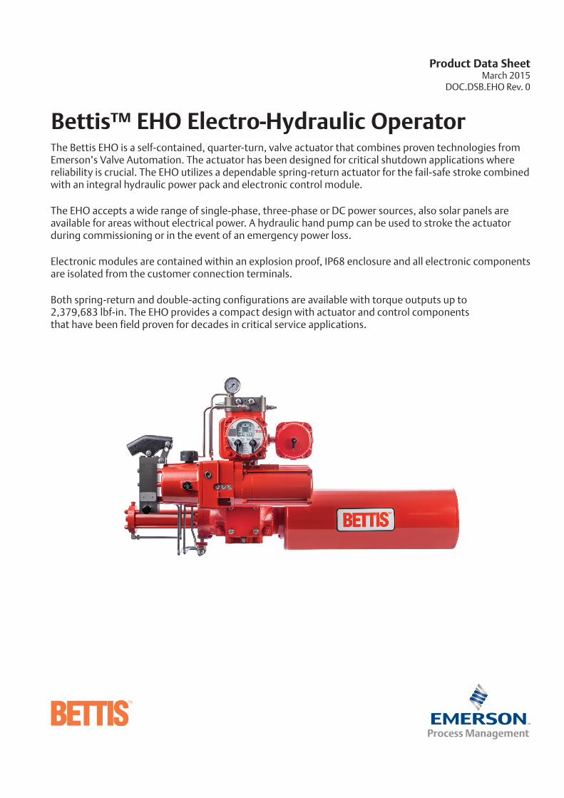
Bettis™ EHO Electro-Hydraulic OperatorThe Bettis EHO is a self-contained, quarter-turn, valve actuator that combines proven technologies from Emerson’s Valve Automation. The actuator has been designed for critical shutdown applications where reliability is crucial. The EHO utilizes a dependable spring-return actuator for the fail-safe stroke combined with an integral hydraulic power pack and electronic control module.
The EHO accepts a wide range of single-phase, three-phase or DC power sources, also solar panels are available for areas without electrical power. A hydraulic hand pump can be used to stroke the actuator during commissioning or in the event of an emergency power loss.
Electronic modules are contained within an explosion proof, IP68 enclosure and all electronic components are isolated from the customer connection terminals.
Both spring-return and double-acting configurations are available with torque outputs up to 2,379,683 lbf-in. The EHO provides a compact design with actuator and control components that have been field proven for decades in critical service applications.
Product Data Sheet March 2015 DOC.DSB.EHO Rev. 0
Table of Contents
Section 1: Product Attributes ...........................................................................3
Section 2: General Specifications .....................................................................4
Section 3: Torque Output Data......................................................................6
Spring-Return, Fail-Safe Actuator ...........................................6
Double-Acting Actuator ........................................................7
Section 4: Model Code Information................................................................9
Spring-Return, Fail-Safe Actuator ...........................................9
Double-Acting Actuator ........................................................11
Section 5: Dimension.....................................................................................13
Spring-Return, Fail-Safe Actuator ...........................................13
Double-Acting Actuator ........................................................14
EHO Product Data SheetMarch 2015 Table of Contents
2

Product Attributes
�� Easy Installation – Bettis™ EHO actuator is a totally self-contained system and designed for compactness and adaptable to new or existing valves
�� BettisTM G-Series hydraulic double-acting or spring-return, fail-safe actuator
�� ShaferTM hydraulic control technology
�� EIMTM electronics and communication technology
�� Multiple input power options with either AC or DC
�� Local lockable Remote/Local/Offline switch
�� Local open/close/stop switch
�� Partial-stroke test
�� Fast speed of operation to fail-safe position if required
�� Emergency shutdown – independent safety circuits and solenoid valve
�� Dual sealed Separate Terminal Chamber, allows installation wiring to be performed or fuses to be replaced without exposing control components to hostile environmental conditions
�� Control enclosure is made of low-copper aluminum alloy, powder-coated, salt-resistant also rated for IP68 ingress protection
�� Hydraulic hand pump manual override
�� Accumulators (optional)
�� Solar power (optional)
�� Operating pressures up to 3000 psi with standard components
�� Easy control over actuator stroking speeds – The stroking speed is controlled through adjustable hydraulic flow control valves. This enables field personnel to easily adjust actuator stroking speed to comply with field requirements
3
Product Data Sheet EHO March 2015
33
EHO.01.01.EN, Page 1 of 1, Rev. 0
4
EHO Product Data SheetMarch 2015
General Specifications
Input Power (AC)
�� Three-phase 50 Hz�— 220, 230, 240, 380, 400, 440, 460, 480, 500,
550, 575, 600 volts
�� Three-phase 60 Hz�— 208, 220, 230, 380, 440, 460, 480, 575,
600 volts
�� Single-phase 50 Hz�— 110, 115, 220, 230, 240 volts
�� Single-phase 60 Hz�— 115, 120, 208, 220, 230 volts
(DC)
�� 24 volts Note: The nominal operating voltage must be specified at time of order. Published actuator performance data is for power supply variations of a ± 10% voltage and a ± 5Hz frequency. If power supply variations are outside these limits, please consult Valve Automation to ensure that actuator performance meets your requirements.
Power Consumption (AC Units)
�� 16.2 W steady state, Running 18.2 W plus motor consumption
(DC Units)
�� 10.0 W steady state , Running 11.0 W plus motor consumption
Conduit Entry Sizes
�� Two 1” NPT, One 1.5” NPT bottom entry
�� One 1” NPT top entry
Local Operation and Display
�� Open/Close/Stop push buttons
�� Remote/Local/Offline lockable selector switch
�� Open/Close display lights
�� Local position indicator
�� Hydraulic hand pump manual override
Remote Operation (Inputs)
�� Open/Close Stop
�� ESD
(Outputs)
�� Open/Close position feedback
�� 4 – 20mA hydraulic pressure (optional)
�� Low hydraulic pressure alarm
EHO.01.02.EN, Page 1 of 2, Rev. 0
5
Product Data Sheet EHO March 2015
Limit Switches
�� 2 SPDT: 4 A @ 120 VAC, 3A @ 24 VDC
�� 4 SPDT (optional): 4 A @ 120 VAC, 3 A @ 24 VDC
Operating Temperature
�� -20°F to +140°F (-29°C to +60°C)
�� -40°F to +140°F (-40°C to +60°C) optional
Hydraulic Fluid
�� CONOCO Megaflow®AW HVI 15 For temperatures down to -20°F (-29°C)
�� EXXON Univis J13 For temperatures down to -40°F (-40°C)
Ingress Protection
�� Control enclosure: IP68
�� Hydraulic actuator: IP67M
�� Motor: IP68
�� Reservoir: IP54
Hazardous Area Classification and SIL Certification
�� CSA, Canadian Standard Association Certification �— Class I, Division I, Groups, C and D�— Group B configuration upon request
�� FM, Factory Mutual Certification�— Class I, II, and III, Groups C, D, E, F, G,
Division I, T4�— Group B configuration upon request
�� ATEX Directive�— EExd IIB T4
�� IECEx Certificate of Conformity�— Ex d IIB T4
�� SIL II Certification
EHO.01.02.EN, Page 2 of 2, Rev. 0
General Specifications (continuation)
Spring Cycle(lbf-in)
Pressure Cycle @ 2500 psig(lbf-in)
or designated pressure
Pressure Cycle @ 3000 psig(lbf-in)
or designated pressure
Spring-ReturnModel
ActuatorMOP (psig)
ActuatorDISPL (in3)
Spring ETC
(lbf-in)
SpringRUN
(lbf-in)
Spring BTC
(lbf-in)
Pressure BTO
@ 2500 psigUnless
indicated(lbf-in)
Pressure@ 2500 psig
RUN (lbf-in)
Pressure ETO
@ 2500 psig (lbf-in)
Pressure BTO
@ 3000 psig (lbf-in)
Pressure@ 3000 psig
RUN (lbf-in)
Pressure ETO
@ 3000 psig (lbf-in)
Stroke Time Power
Cycle(seconds)
AC 3-Phase
Stroke Time Pressure
Cycle(seconds)½ HP DC
Motor
SRStroke
Time to Fail Position
(seconds)
Motor HP
Required
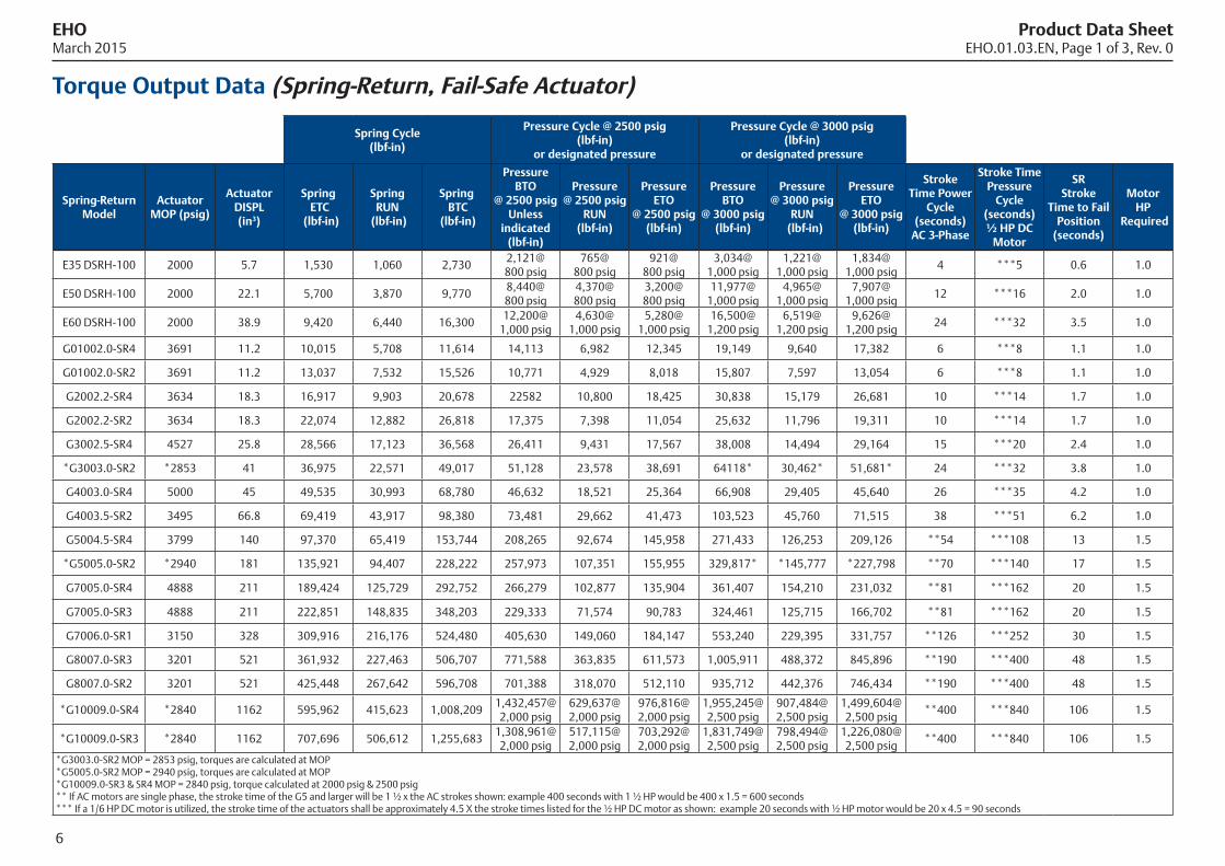
E35 DSRH-100 2000 5.7 1,530 1,060 2,7302,121@ 800 psig
765@ 800 psig
921@ 800 psig
3,034@ 1,000 psig
1,221@ 1,000 psig
1,834@ 1,000 psig
4 ***5 0.6 1.0
E50 DSRH-100 2000 22.1 5,700 3,870 9,7708,440@ 800 psig
4,370@ 800 psig
3,200@ 800 psig
11,977@ 1,000 psig
4,965@ 1,000 psig
7,907@ 1,000 psig
12 ***16 2.0 1.0
E60 DSRH-100 2000 38.9 9,420 6,440 16,30012,200@
1,000 psig4,630@
1,000 psig5,280@
1,000 psig16,500@
1,200 psig6,519@
1,200 psig9,626@
1,200 psig24 ***32 3.5 1.0
G01002.0-SR4 3691 11.2 10,015 5,708 11,614 14,113 6,982 12,345 19,149 9,640 17,382 6 ***8 1.1 1.0
G01002.0-SR2 3691 11.2 13,037 7,532 15,526 10,771 4,929 8,018 15,807 7,597 13,054 6 ***8 1.1 1.0
G2002.2-SR4 3634 18.3 16,917 9,903 20,678 22582 10,800 18,425 30,838 15,179 26,681 10 ***14 1.7 1.0
G2002.2-SR2 3634 18.3 22,074 12,882 26,818 17,375 7,398 11,054 25,632 11,796 19,311 10 ***14 1.7 1.0
G3002.5-SR4 4527 25.8 28,566 17,123 36,568 26,411 9,431 17,567 38,008 14,494 29,164 15 ***20 2.4 1.0
*G3003.0-SR2 *2853 41 36,975 22,571 49,017 51,128 23,578 38,691 64118* 30,462* 51,681* 24 ***32 3.8 1.0
G4003.0-SR4 5000 45 49,535 30,993 68,780 46,632 18,521 25,364 66,908 29,405 45,640 26 ***35 4.2 1.0
G4003.5-SR2 3495 66.8 69,419 43,917 98,380 73,481 29,662 41,473 103,523 45,760 71,515 38 ***51 6.2 1.0
G5004.5-SR4 3799 140 97,370 65,419 153,744 208,265 92,674 145,958 271,433 126,253 209,126 **54 ***108 13 1.5
*G5005.0-SR2 *2940 181 135,921 94,407 228,222 257,973 107,351 155,955 329,817* *145,777 *227,798 **70 ***140 17 1.5
G7005.0-SR4 4888 211 189,424 125,729 292,752 266,279 102,877 135,904 361,407 154,210 231,032 **81 ***162 20 1.5
G7005.0-SR3 4888 211 222,851 148,835 348,203 229,333 71,574 90,783 324,461 125,715 166,702 **81 ***162 20 1.5
G7006.0-SR1 3150 328 309,916 216,176 524,480 405,630 149,060 184,147 553,240 229,395 331,757 **126 ***252 30 1.5
G8007.0-SR3 3201 521 361,932 227,463 506,707 771,588 363,835 611,573 1,005,911 488,372 845,896 **190 ***400 48 1.5
G8007.0-SR2 3201 521 425,448 267,642 596,708 701,388 318,070 512,110 935,712 442,376 746,434 **190 ***400 48 1.5
*G10009.0-SR4 *2840 1162 595,962 415,623 1,008,2091,432,457@ 2,000 psig
629,637@ 2,000 psig
976,816@ 2,000 psig
1,955,245@ 2,500 psig
907,484@ 2,500 psig
1,499,604@ 2,500 psig
**400 ***840 106 1.5
*G10009.0-SR3 *2840 1162 707,696 506,612 1,255,6831,308,961@ 2,000 psig
517,115@ 2,000 psig
703,292@ 2,000 psig
1,831,749@ 2,500 psig
798,494@ 2,500 psig
1,226,080@ 2,500 psig
**400 ***840 106 1.5
*G3003.0-SR2 MOP = 2853 psig, torques are calculated at MOP*G5005.0-SR2 MOP = 2940 psig, torques are calculated at MOP*G10009.0-SR3 & SR4 MOP = 2840 psig, torque calculated at 2000 psig & 2500 psig ** If AC motors are single phase, the stroke time of the G5 and larger will be 1 ½ x the AC strokes shown: example 400 seconds with 1 ½ HP would be 400 x 1.5 = 600 seconds *** If a 1/6 HP DC motor is utilized, the stroke time of the actuators shall be approximately 4.5 X the stroke times listed for the ½ HP DC motor as shown: example 20 seconds with ½ HP motor would be 20 x 4.5 = 90 seconds
Torque Output Data (Spring-Return, Fail-Safe Actuator)
EHO Product Data SheetMarch 2015 EHO.01.03.EN, Page 1 of 3, Rev. 0
6
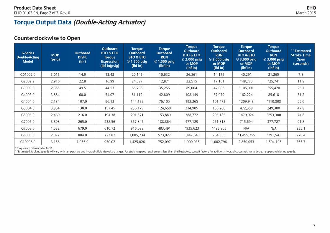
G-Series Double-Acting
Model
MOP(psig)
Outboard DISPL(In3)
OutboardBTO & ETO
Torque Expression(lbf-in/psig)
Torque OutboardBTO & ETO
@ 1,500 psig(lbf-in)
TorqueOutboard
RUN@ 1,500 psig
(lbf-in)
TorqueOutboardBTO & ETO
@ 2,000 psig or MOP(lbf-in)
Torque Outboard
RUN @ 2,000 psig
or MOP(lbf-in)
Torque OutboardBTO & ETO
@ 3,000 psig or MOP(lbf-in)
Torque Outboard
RUN@ 3,000 psig
or MOP(lbf-in)
**EstimatedStroke Time
Open (seconds)
G01002.0 3,015 14.9 13.43 20,145 10,632 26,861 14,176 40,291 21,265 7.8
G2002.2 2,916 22.8 16.99 24,387 12,871 32,515 17,161 *48,773 *25,741 11.8
G3003.0 2,358 49.5 44.53 66,798 35,255 89,064 47,006 *105,001 *55,420 25.7
G4003.0 3,884 60.0 54.07 81,112 42,809 108,149 57,079 162,224 85,618 31.2
G4004.0 2,184 107.0 96.13 144,199 76,105 192,265 101,473 *209,948 *110,808 55.6
G5004.0 3,854 138.0 157.45 236,179 124,650 314,905 166,200 472,358 249,300 47.8
G5005.0 2,469 216.0 194.38 291,571 153,889 388,772 205,185 *479,924 *253,300 74.8
G7005.0 3,898 265.0 238.56 357,847 188,864 477,129 251,818 715,694 377,727 91.8
G7008.0 1,532 679.0 610.72 916,088 483,491 *935,623 *493,805 N/A N/A 235.1
G8008.0 2,072 804.0 723.82 1,085,734 573,027 1,447,646 764,035 *1,499,755 *791,541 278.4
G10008.0 3,158 1,056.0 950.02 1,425,026 752,097 1,900,035 1,002,796 2,850,053 1,504,195 365.7
*Torques are calculated at MOP **Estimated Stroking speeds will vary with temperature and hydraulic fluid viscosity changes. For stroking speed requirements less than the illustrated, consult factory for additional hydraulic accumulator to decrease open and closing speeds.
Torque Output Data (Double-Acting Actuator) Counterclockwise to Open
Product Data Sheet EHOEHO.01.03.EN, Page 2 of 3, Rev. 0 March 2015
7
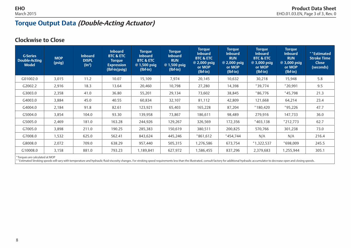
EHO Product Data SheetMarch 2015 EHO.01.03.EN, Page 3 of 3, Rev. 0
8
G-Series Double-Acting
Model
MOP(psig)
Inboard DISPL(In3)
Inboard BTC & ETC
Torque Expression(lbf-in/psig)
Torque Inboard
BTC & ETC@ 1,500 psig
(lbf-in)
TorqueInboard
RUN@ 1,500 psig
(lbf-in)
TorqueInboard
BTC & ETC@ 2,000 psig
or MOP(lbf-in)
Torque Inboard
RUN @ 2,000 psig
or MOP(lbf-in)
Torque Inboard
BTC & ETC@ 3,000 psig
or MOP(lbf-in)
Torque Inboard
RUN@ 3,000 psig
or MOP(lbf-in)
**EstimatedStroke Time
Close (seconds)
G01002.0 3,015 11.2 10.07 15,109 7,974 20,145 10,632 30,218 15,948 5.8
G2002.2 2,916 18.3 13.64 20,460 10,798 27,280 14,398 *39,774 *20,991 9.5
G3003.0 2,358 41.0 36.80 55,201 29,134 73,602 38,845 *86,776 *45,798 21.3
G4003.0 3,884 45.0 40.55 60,834 32,107 81,112 42,809 121,668 64,214 23.4
G4004.0 2,184 91.8 82.61 123,921 65,403 165,228 87,204 *180,420 *95,226 47.7
G5004.0 3,854 104.0 93.30 139,958 73,867 186,611 98,489 279,916 147,733 36.0
G5005.0 2,469 181.0 163.28 244,926 129,267 326,569 172,356 *403,138 *212,773 62.7
G7005.0 3,898 211.0 190.25 285,383 150,619 380,511 200,825 570,766 301,238 73.0
G7008.0 1,532 625.0 562.41 843,624 445,246 *861,612 *454,744 N/A N/A 216.4
G8008.0 2,072 709.0 638.29 957,440 505,315 1,276,586 673,754 *1,322,537 *698,009 245.5
G10008.0 3,158 881.0 793.23 1,189,841 627,972 1,586,455 837,296 2,379,683 1,255,944 305.1
*Torques are calculated at MOP **Estimated Stroking speeds will vary with temperature and hydraulic fluid viscosity changes. For stroking speed requirements less than the illustrated, consult factory for additional hydraulic accumulator to decrease open and closing speeds.
Torque Output Data (Double-Acting Actuator) Clockwise to Close
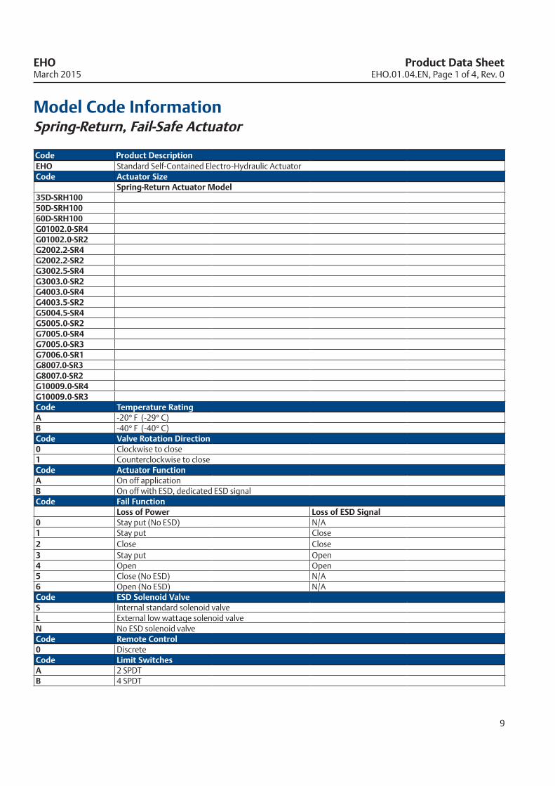
Model Code InformationSpring-Return, Fail-Safe Actuator
Code Product DescriptionEHO Standard Self-Contained Electro-Hydraulic ActuatorCode Actuator Size
Spring-Return Actuator Model 35D-SRH10050D-SRH10060D-SRH100G01002.0-SR4G01002.0-SR2G2002.2-SR4G2002.2-SR2G3002.5-SR4G3003.0-SR2G4003.0-SR4G4003.5-SR2G5004.5-SR4G5005.0-SR2G7005.0-SR4G7005.0-SR3G7006.0-SR1G8007.0-SR3G8007.0-SR2G10009.0-SR4G10009.0-SR3Code Temperature RatingA -20° F (-29° C)B -40° F (-40° C)Code Valve Rotation Direction0 Clockwise to close1 Counterclockwise to closeCode Actuator FunctionA On off application B On off with ESD, dedicated ESD signal Code Fail Function
Loss of Power Loss of ESD Signal 0 Stay put (No ESD) N/A1 Stay put Close2 Close Close3 Stay put Open4 Open Open5 Close (No ESD) N/A6 Open (No ESD) N/ACode ESD Solenoid ValveS Internal standard solenoid valveL External low wattage solenoid valveN No ESD solenoid valveCode Remote Control0 Discrete Code Limit SwitchesA 2 SPDTB 4 SPDT
EHO.01.04.EN, Page 1 of 4, Rev. 0
9
EHO Product Data SheetMarch 2015
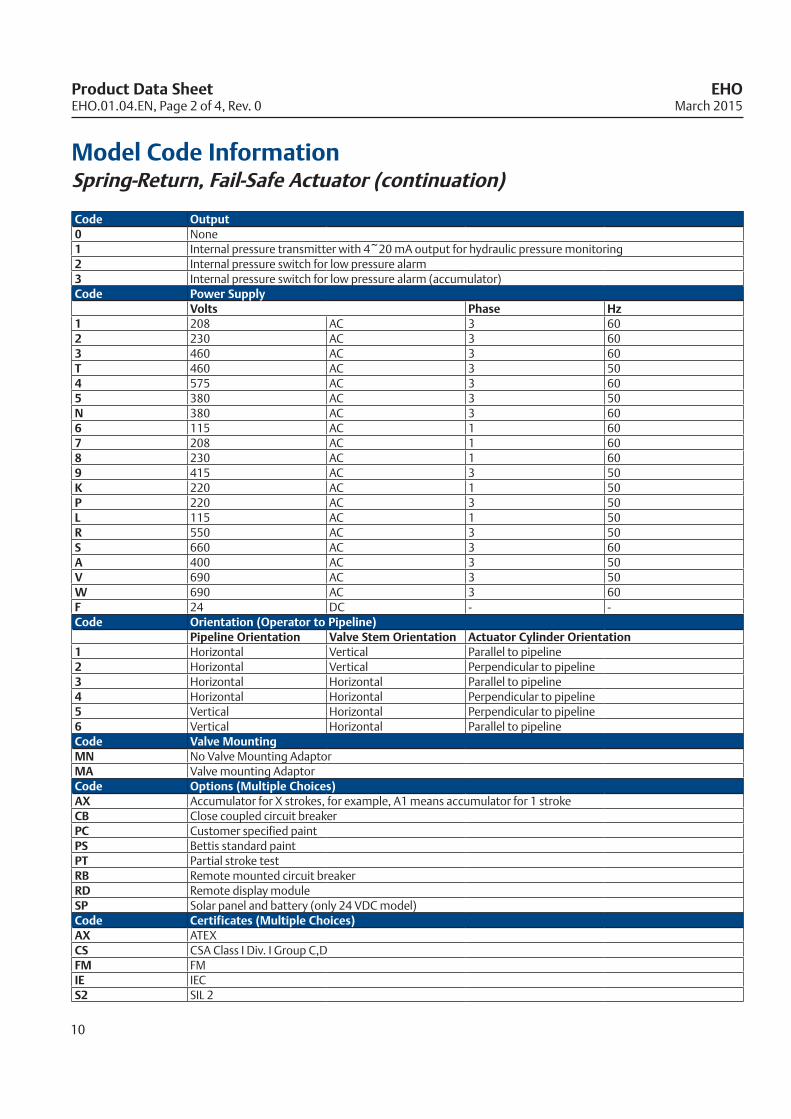
Code Output0 None1 Internal pressure transmitter with 4~20 mA output for hydraulic pressure monitoring2 Internal pressure switch for low pressure alarm3 Internal pressure switch for low pressure alarm (accumulator)Code Power Supply
Volts Phase Hz1 208 AC 3 602 230 AC 3 603 460 AC 3 60T 460 AC 3 504 575 AC 3 605 380 AC 3 50N 380 AC 3 606 115 AC 1 607 208 AC 1 608 230 AC 1 609 415 AC 3 50K 220 AC 1 50P 220 AC 3 50L 115 AC 1 50R 550 AC 3 50S 660 AC 3 60A 400 AC 3 50V 690 AC 3 50W 690 AC 3 60F 24 DC - -Code Orientation (Operator to Pipeline)
Pipeline Orientation Valve Stem Orientation Actuator Cylinder Orientation1 Horizontal Vertical Parallel to pipeline2 Horizontal Vertical Perpendicular to pipeline3 Horizontal Horizontal Parallel to pipeline4 Horizontal Horizontal Perpendicular to pipeline5 Vertical Horizontal Perpendicular to pipeline6 Vertical Horizontal Parallel to pipelineCode Valve MountingMN No Valve Mounting Adaptor MA Valve mounting Adaptor Code Options (Multiple Choices)AX Accumulator for X strokes, for example, A1 means accumulator for 1 strokeCB Close coupled circuit breakerPC Customer specified paintPS Bettis standard paintPT Partial stroke testRB Remote mounted circuit breakerRD Remote display moduleSP Solar panel and battery (only 24 VDC model)Code Certificates (Multiple Choices)AX ATEXCS CSA Class I Div. I Group C,DFM FMIE IECS2 SIL 2
Model Code InformationSpring-Return, Fail-Safe Actuator (continuation)
Product Data Sheet EHO March 2015 EHO.01.04.EN, Page 2 of 4, Rev. 0
10
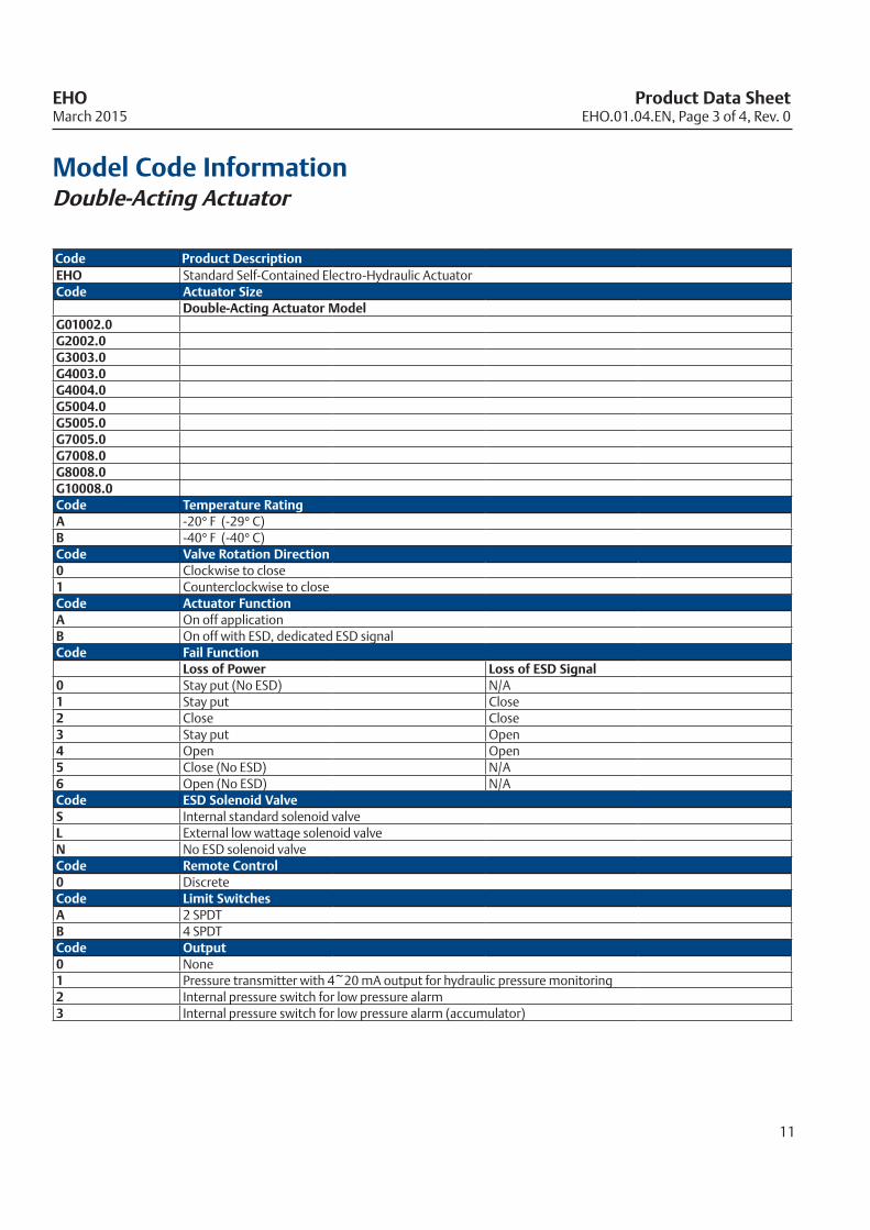
Model Code InformationDouble-Acting Actuator
Code Product DescriptionEHO Standard Self-Contained Electro-Hydraulic ActuatorCode Actuator Size
Double-Acting Actuator Model G01002.0G2002.0G3003.0G4003.0G4004.0G5004.0G5005.0G7005.0G7008.0G8008.0G10008.0Code Temperature RatingA -20° F (-29° C)B -40° F (-40° C)Code Valve Rotation Direction0 Clockwise to close1 Counterclockwise to closeCode Actuator FunctionA On off application B On off with ESD, dedicated ESD signal Code Fail Function
Loss of Power Loss of ESD Signal 0 Stay put (No ESD) N/A1 Stay put Close2 Close Close3 Stay put Open4 Open Open5 Close (No ESD) N/A6 Open (No ESD) N/ACode ESD Solenoid ValveS Internal standard solenoid valveL External low wattage solenoid valveN No ESD solenoid valveCode Remote Control0 Discrete Code Limit SwitchesA 2 SPDTB 4 SPDTCode Output0 None1 Pressure transmitter with 4~20 mA output for hydraulic pressure monitoring2 Internal pressure switch for low pressure alarm3 Internal pressure switch for low pressure alarm (accumulator)
EHO.01.04.EN, Page 3 of 4, Rev. 0
11
EHO Product Data SheetMarch 2015
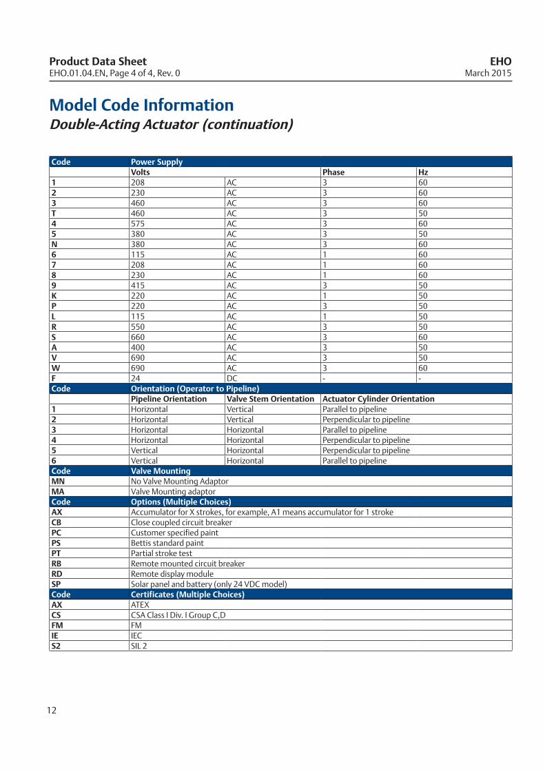
Code Power SupplyVolts Phase Hz
1 208 AC 3 602 230 AC 3 603 460 AC 3 60T 460 AC 3 504 575 AC 3 605 380 AC 3 50N 380 AC 3 606 115 AC 1 607 208 AC 1 608 230 AC 1 609 415 AC 3 50K 220 AC 1 50P 220 AC 3 50L 115 AC 1 50R 550 AC 3 50S 660 AC 3 60A 400 AC 3 50V 690 AC 3 50W 690 AC 3 60F 24 DC - -Code Orientation (Operator to Pipeline)
Pipeline Orientation Valve Stem Orientation Actuator Cylinder Orientation1 Horizontal Vertical Parallel to pipeline2 Horizontal Vertical Perpendicular to pipeline3 Horizontal Horizontal Parallel to pipeline4 Horizontal Horizontal Perpendicular to pipeline5 Vertical Horizontal Perpendicular to pipeline6 Vertical Horizontal Parallel to pipelineCode Valve MountingMN No Valve Mounting Adaptor MA Valve Mounting adaptor Code Options (Multiple Choices)AX Accumulator for X strokes, for example, A1 means accumulator for 1 strokeCB Close coupled circuit breakerPC Customer specified paintPS Bettis standard paintPT Partial stroke testRB Remote mounted circuit breakerRD Remote display moduleSP Solar panel and battery (only 24 VDC model)Code Certificates (Multiple Choices)AX ATEXCS CSA Class I Div. I Group C,DFM FMIE IECS2 SIL 2
Model Code InformationDouble-Acting Actuator (continuation)
12
Product Data Sheet EHO March 2015 EHO.01.04.EN, Page 4 of 4, Rev. 0

DimensionSpring-Return, Fail-Safe Actuator
12378
Copyright © 2014 Emerson Process Management Valve Automation, Inc.
A
3-VA
ED-A
45610 912 11
B
C
D
E
F
G
H
A
B
C
D
E
F
G
H
12378 45610 912 11
A
B
C
CYLINDER CL
MANUAL OVERRIDE
HYDRAULICMANIFOLDASSEMBLY
CYLINDER CL
E
VALVE CL
2X STOP ADJUSTMENTSCREW
SPRING MODULE
POWER MODULE
PRESSURE GAUGE
VALVE CL
CYLINDER CL
VALVE MOUNTING SURFACED
CIRCUIT BREAKER MODULE
LOCAL DISPLAY MODULE(Local/Remote Operation)
INCH MM INCH MM INCH MM INCH MM INCH MM Lbs KGG01002.0-SR2-CW 54.0 1371.6 22.6 574.0 28.1 713.7 72.7 1846.6 2.4 61.0 669 303G01002.0-SR4-CW 54.0 1371.6 22.6 574.0 28.1 713.7 72.7 1846.6 2.4 61.0 655 297G2002.2-SR2-CW 57.8 1468.1 22.6 574.0 28.7 729.0 76.9 1953.3 2.9 73.7 774 351G2002.2-SR4-CW 57.8 1468.1 22.6 574.0 28.7 729.0 76.9 1953.3 2.9 73.7 759 344G3002.5-SR4-CW 65.5 1663.7 22.6 574.0 32.1 815.3 80.1 2034.5 3.5 88.9 916 415G3003.0-SR2-CW 65.5 1663.7 22.6 574.0 32.1 815.3 80.1 2034.5 3.5 88.9 945 429G4003.0-SR4-CW 76.2 1935.5 27.7 703.6 31.7 805.2 85.9 2181.9 4.3 109.2 1229 557G4003.5-SR2-CW 76.2 1935.5 27.7 703.6 31.7 805.2 85.9 2181.9 4.3 109.2 1313 596G5004.5-SR4-CW 89.0 2260.6 31.1 789.9 35.9 911.9 93.9 2385.1 5.5 139.7 1970 894G5005.0-SR2-CW 89.0 2260.6 31.1 789.9 35.9 911.9 93.9 2385.1 5.5 139.7 2099 952G7005.0-SR3-CW 105.6 2682.2 35.7 906.8 42.4 1077.0 103.0 2616.2 6.8 172.7 3238 1469G7005.0-SR4-CW 105.6 2682.2 35.7 906.8 42.4 1077.0 103.0 2616.2 6.8 172.7 3325 1508G7006.0-SR4-CW 105.6 2682.2 35.7 906.8 42.4 1077.0 103.0 2616.2 6.8 172.7 3312 1502G8007.0-SR2-CW 139.7 3548.4 36.9 937.3 43.1 1094.7 131.0 3327.4 8.0 203.2 5447 2471G8007.0-SR3-CW 139.7 3548.4 36.9 937.3 43.1 1094.7 131.0 3327.4 8.0 203.2 5427 2462G10009.0-SR4-CW 168.6 4282.4 39.4 1000.8 45.3 1150.6 148.0 3759.2 10.5 266.7 7497 3401
OUTLINE DIMENSION AND DETAILS
Actuator A B C D E ApproximateWeight
OUTLINE DIMENSION AND DETAILS
ActuatorA B C D E Approximate
WeightINCH MM INCH MM INCH MM INCH MM INCH MM Lbs KG
G01002.0-SR2-CW 54.0 1371.6 22.6 574.0 28.1 713.7 72.7 1846.6 2.4 61.0 669 303G01002.0-SR4-CW 54.0 1371.6 22.6 574.0 28.1 713.7 72.7 1846.6 2.4 61.0 655 297G2002.2-SR2-CW 57.8 1468.1 22.6 574.0 28.1 729.0 76.9 1953.3 2.9 73.7 774 351G2002.2-SR4-CW 57.8 1468.1 22.6 574.0 28.1 729.0 76.9 1953.3 2.9 73.7 759 344G3002.5-SR4-CW 65.5 1663.7 22.6 574.0 32.1 815.3 80.1 2034.5 3.5 88.9 916 415G3003.0-SR2-CW 65.5 1663.7 22.6 574.0 32.1 815.3 80.1 2034.5 3.5 88.9 945 429G4003.0-SR4-CW 76.2 1935.5 27.7 703.6 31.7 805.2 85.9 2181.9 4.3 109.2 1229 557G4003.5-SR2-CW 76.2 1935.5 27.7 703.6 31.7 805.2 85.9 2181.9 4.3 109.2 1313 596G5004.5-SR4-CW 89.0 2260.6 31.1 789.9 35.9 911.9 93.9 2385.1 5.5 139.7 1970 894G5005.0-SR2-CW 89.0 2260.6 31.1 789.9 35.9 911.9 93.9 2385.1 5.5 139.7 2099 952G7005.0-SR3-CW 105.6 2682.2 35.7 906.8 42.4 1077.0 103.0 2616.2 6.8 172.7 3238 1469G7005.0-SR4-CW 105.6 2682.2 35.7 906.8 42.4 1077.0 103.0 2616.2 6.8 172.7 3325 1508G7006.0-SR4-CW 105.6 2682.2 35.7 906.8 42.4 1077.0 103.0 2616.2 6.8 172.7 3312 1502G8007.0-SR2-CW 139.7 3548.4 36.9 937.3 43.1 1094.7 131.0 3327.4 8.0 203.2 5447 2471G8007.0-SR3-CW 139.7 3548.4 36.9 937.3 43.1 1094.7 131.0 3327.4 8.0 203.2 5427 2462
G10009.0-SR4-CW 168.6 4282.4 39.4 1000.8 45.3 1150.6 148.0 3759.2 61.0 266.7 7497 3401
EHO.01.05.EN, Page 1 of 2, Rev. 0
13
EHO Product Data SheetMarch 2015

DimensionDouble-Acting Actuator
INCH MM INCH MM INCH MM INCH MM INCH MM Lbs KGG01001.5 39.8 1010.9 27.7 703.6 28.3 718.8 57.9 1470.7 2.4 61.0 513 233G2002.0 40.6 1031.2 28.7 729.0 29.0 736.6 58.3 1480.8 2.9 73.7 546 248G3004.0 46.8 1188.7 30.1 764.5 32.5 825.5 61.5 1562.1 3.5 88.9 626 284G4003.0 52.0 1320.8 34.5 876.3 31.9 810.3 66.8 1696.7 4.3 109.2 770 349G4004.0 53.0 1346.2 35.5 901.7 32.9 835.7 67.8 1722.1 5.3 134.6 783 355G5004.0 58.3 1480.8 37.4 950.0 34.8 883.9 73.2 1859.3 5.5 139.7 1141 518G5005.0 59.3 1506.2 38.4 975.4 35.8 909.3 74.2 1884.7 6.5 165.1 1300 590G7005.0 64.3 1633.2 40.4 1026.2 39.7 1008.4 81.6 2072.6 6.8 172.7 1786 810G7008.0 65.3 1658.6 41.4 1051.6 40.7 1033.8 82.6 2098.0 7.8 198.1 1829 830G8008.0 76.5 1943.1 427.0 10845.8 39.5 1003.3 87.5 2222.5 8.0 203.2 2461 1116G10008.0 93.6 2377.4 46.9 1191.3 43.6 1107.4 99.4 2524.8 10.5 266.7 3754 1703
OUTLINE DIMENSION AND DETAILS
Actuator A B C D E
Approximate Weight
OUTLINE DIMENSION AND DETAILS
ActuatorA B C D E Approximate
WeightINCH MM INCH MM INCH MM INCH MM INCH MM Lbs KG
G01001.5 39.8 1010.9 27.7 703.6 28.3 718.8 57.9 1470.7 2.4 61.0 513 233G2002.0 40.6 1031.2 28.7 729.0 29.0 736.6 58.3 1480.8 2.9 73.7 546 248G3004.0 46.8 1188.7 30.1 764.5 32.5 825.5 61.5 1562.1 3.5 88.9 626 284G4003.0 52.0 1320.8 34.5 876.3 31.9 810.3 66.8 1696.7 4.3 109.2 770 349G4004.0 53.0 1346.2 35.5 901.7 32.9 835.7 67.8 1722.1 5.3 134.6 783 355G5004.0 58.3 1480.8 37.4 950.0 34.8 883.9 73.2 1859.3 5.5 139.7 1141 518G5005.0 59.3 1506.2 38.4 975.4 35.8 909.3 74.2 1884.7 6.5 165.1 1300 590G7005.0 64.3 1633.2 40.4 1026.2 39.7 1008.4 81.6 2072.6 6.8 172.7 1786 810G7008.0 65.3 1658.6 41.4 1051.6 40.7 1033.8 82.6 2098.0 7.8 198.1 1829 830G8008.0 76.5 1943.1 427.0 1085.8 39.5 1003.3 87.5 2222.5 8.0 203.2 2461 1116
G10008.0 93.6 2377.4 46.9 1191.3 43.6 1107.4 99.4 2524.8 10.5 266.7 3754 1703
14
Product Data Sheet EHO March 2015 EHO.01.05.EN, Page 2 of 2, Rev. 0
World Area Configuration Centers (WACC) offer sales support, service, inventory and commissioning to our global customers. Choose the WACC or sales office nearest you:
www.emersonprocess.com/bettis
©2015 Emerson Process Management. All rights reserved. The Emerson logo is a trademark and service mark of Emerson Electric Co. Bettis is a mark of one of the Emerson Process Management family of companies. All other marks are property of their respective owners. The contents of this publication are presented for information purposes only, and while every effort has been made to ensure their accuracy, they are not to be construed as warranties or guarantees, express or implied, regarding the products or services described herein or their use or applicability. All sales are governed by our terms and conditions, which are available on request. We reserve the right to modify or improve the designs or specifications of our products at any time without notice.
NORTH & SOUTH AMERICA 19200 Northwest Freeway Houston, TX 77065 T +1 281 477 4100 F +1 281 477 2809Av. Hollingsworth, 325, Iporanga Sorocaba, SP 18087-105 Brazil T +55 15 3238 3788 F +55 15 3228 3300
ASIA PACIFIC No. 9 Gul Road #01-02 Singapore 629361 T +65 6501 4600 F +65 6268 0028 No.1 Lai Yuan Road Wuqing Development Area Tianjin 301700 P.R.China T +86 22 8212 3300 F +86 22 8212 3308
MIDDLE EAST & AFRICA P. O. Box 17033 Dubai United Arab Emirates T +971 4 811 8100 F +971 4 886 5465
P. O. Box 10305 Jubail 31961 Saudi Arabia T +966 3 340 8650 F +966 3 340 8790
24 Angus Crescent Longmeadow Business Estate East P.O. Box 6908; Greenstone; 1616 Modderfontein, Extension 5 South AfricaT +27 11 451 3700F +27 11 451 3800
EUROPE Asveldweg 11 7556 BR Hengelo (O) The Netherlands T +31 74 256 1010 F +31 74 291 0938
For complete list of sales and manufacturing sites, please visit www.emersonprocess.com/valveautomationlocations Or contact us at info.valveautomationatemerson.com