best practices for virtualizing & managing exchange 2013
TRANSCRIPT

Best Practices for Virtualizing and Managing Exchange 2013 1
1
Best Practices for
Virtualizing & Managing
Exchange 2013 v1.1 – July 2015

Best Practices for Virtualizing and Managing Exchange 2013 2
2
Copyright Information © 2013 Microsoft Corporation. All rights reserved. This document is provided "as-is." Information and
views expressed in this document, including URL and other Internet Web site references, may change
without notice. You bear the risk of using it. This document does not provide you with any legal rights to
any intellectual property in any Microsoft product. You may copy and use this document for your internal,
reference purposes. You may modify this document for your internal, reference purposes.

Best Practices for Virtualizing and Managing Exchange 2013 3
3
Table of Contents Introduction .......................................................................................... 5
Executive Summary .......................................................................................................................................................... 5
Target Audience ................................................................................................................................................................ 6
Scope ....................................................................................................................................................................................... 6
Why Virtualize Exchange? ............................................................... 7
Why Microsoft Virtualization and Management? ................... 8
Fabric Configuration .......................................................................... 9
Hardware Considerations ............................................................................................................................................. 9
Compute Considerations ............................................................................................................................................ 12
Storage Considerations ............................................................................................................................................... 17
Networking Considerations ....................................................................................................................................... 29
Host Resiliency & VM Agility ......................................................... 35
Host Clustering ................................................................................................................................................................. 35
Virtual Machine Configuration ..................................................... 44
General Supportability.................................................................................................................................................. 44
Microsoft Assessment and Planning Toolkit .................................................................................................... 44
Exchange 2013 Server Role Requirements Calculator ................................................................................ 45
Exchange 2013 Virtual Machine CPU Considerations ................................................................................. 45
Exchange 2013 Virtual Machine Memory Considerations ........................................................................ 47
Exchange 2013 Virtual Machine Storage Considerations ......................................................................... 50
Exchange 2013 Virtual Machine Network Considerations ........................................................................ 54
Exchange 2013 Resiliency ............................................................... 60
Exchange 2013 Roles .................................................................................................................................................... 60

Best Practices for Virtualizing and Managing Exchange 2013 4
4
Single Exchange 2013 Virtual Machine on a Hyper-V Cluster ................................................................ 61
Resilient Exchange Configuration on a Hyper-V Cluster ........................................................................... 62
System Center 2012 SP1 ................................................................. 66
Comprehensive Management Capabilities ....................................................................................................... 66
Virtual Machine Manager ........................................................................................................................................... 66
App Controller .................................................................................................................................................................. 76
Service Manager and Orchestrator ....................................................................................................................... 78
Operations Manager ..................................................................................................................................................... 84
Data Protection Manager ........................................................................................................................................... 87
Conclusion .......................................................................................... 90
Additional Resources ........................................................................ 91

Best Practices for Virtualizing and Managing Exchange 2013 5
5
Introduction This guide provides high-level best practices and considerations for deploying and managing Microsoft
Exchange 2013 on a Windows Server 2012 Hyper-V-based virtualization infrastructure. The
recommendations and guidance in this document aim to:
Complement the architectural design of an organization’s specific environment.
Help organizations take advantage of the key platform features in Microsoft Exchange 2013 to
deliver the highest levels of performance and availability in a virtualized environment.
Executive Summary To meet demanding and ever-changing business needs, organizations want their Exchange Server-based
messaging solution to rapidly scale and to be highly available at all times. As the demand for Exchange
Server resources increases within and across organizations, it becomes important for IT to quickly meet
those requirements. At the same time, though, IT is challenged with the need to minimize the cost of
underlying infrastructure, effectively manage risk, and save time and effort on management activities. One
solution to this challenge is virtualization.
Virtualization is now common in organizations of all sizes. Many have moved beyond the nascent stage
into being more advanced users of server virtualization for a variety of workloads, including their
messaging systems. These organizations have gained benefits in the areas of cost, efficiency, operations,
availability, agility, and resiliency.
Windows Server 2012 Hyper-V, with its enhanced capabilities, can be used to effectively virtualize
mission-critical workloads such as Exchange 2013. This guide explains these capabilities in the context of:
How organizations can virtualize Exchange 2013 on Windows Server 2012 Hyper-V.
How organizations can benefit from managing this virtualized environment with Microsoft System
Center 2012 SP1.
Working together, these three industry-leading products deliver an integrated solution that provides low
total cost of ownership (TCO) and offers mission-critical scale, performance, and high availability. The
solution also provides more enhanced end-to-end security, management, and monitoring capabilities.
Further, many organizations now want to go a step beyond and adopt an IT infrastructure that is
optimized for and ready to work in a cloud-based environment. They need an IT infrastructure that can
seamlessly span from a private to a public cloud. To achieve this goal, many organizations choose a
common virtualization platform across the infrastructure. In this regard, Windows Server 2012 Hyper-V
offers the best virtualization platform for Exchange 2013.

Best Practices for Virtualizing and Managing Exchange 2013 6
6
Target Audience This guide is intended for IT professionals and technical decision makers (TDMs), including IT consultants
and architects, IT managers, and messaging administrators. With this guide, IT professionals can better
understand how to set up an environment for virtualizing Exchange 2013 using an integrated
virtualization platform built on some of the latest Microsoft technologies, including Windows Server 2012
Hyper-V and System Center 2012 SP1. In addition, identifying key considerations and best practices can
help TDMs effectively plan and deploy Exchange 2013 in a Hyper-V environment. This guide serves the
following purposes for these key roles:
IT consultants and architects: Understand how the entire virtualization environment will work as
they design the architecture.
IT managers: Design processes to fit the overall virtualization environment so that costs are
reduced and efficiency is increased as much as possible.
Messaging administrators: Understand how Exchange 2013 can be set up and function in the
virtual environment.
Scope This guide focuses on providing an understanding of the key considerations for virtualizing Exchange
2013 on a Windows Server 2012 host system or virtual machine, or as part of an on-premises, hybrid, or
private cloud deployment. At a broad level, the guide is divided into the following sections:
Fabric configuration: Covers the key requirements, features, and considerations for infrastructure
that are necessary to set up the virtualization environment. This includes best practice
considerations for physical hosts and requirements for processors, memory, storage, and
networks.
Fabric/host resiliency: Provides information related to Hyper-V host clustering and resiliency,
and introduces features that enable resiliency on host systems, such as failover clustering and
Cluster Shared Volumes.
Virtual machine configuration for Exchange 2013 and Exchange 2013 resiliency: Highlights
best practice considerations related to configuring virtual machines for Exchange 2013. Provides
information related to Exchange 2013 resiliency in different scenarios, including virtualizing a
single Exchange 2013 virtual machine and creating resilient Exchange 2013 deployments across
multiple hosts.
System Center enhancements: Provides an overview of how System Center 2012 SP1 supports
deploying and managing Exchange 2013 across the infrastructure (that is, on-premises, in the
cloud, or hybrid).

Best Practices for Virtualizing and Managing Exchange 2013 7
7
Why Virtualize Exchange? The demand to virtualize tier-1 applications such as Exchange Server continuously increases as IT
organizations push toward completely virtualized environments to improve efficiency, reduce operational
and capital costs, and improve the management of IT infrastructure. By using Windows Server 2012
Hyper-V to virtualize Exchange application workloads, organizations can overcome potential scalability,
reliability, and performance concerns of virtualizing such a workload.
While Windows Server 2012 Hyper-V and System Center 2012 SP1 meet the deployment, manageability,
and performance requirements necessary to virtualize an Exchange 2013 environment with confidence,
the unique nature of Exchange Server means the choice of whether or not to virtualize Exchange
workloads should be considered carefully. According to a February 2013 lab validation report from the
Enterprise Strategy Group (ESG), “Capacity planning and performance analysis of existing Exchange
deployments is recommended to not only determine if your organization’s workload is suitable for
virtualization, but also to plan the processor, memory, and network resources that need to be configured
within each virtual machine.”1 This guide examines some of these considerations and provides
recommendations to enable the best performance, reliability, and manageability when virtualizing
Exchange Server.
Best Practices for Virtualizing and Managing Exchange 2013 8
8
Why Microsoft Virtualization
and Management? Organizations today want the ability to consistently and coherently develop, deploy, and manage their
services and applications across on-premises and cloud environments. Microsoft offers a consistent and
integrated platform that spans from on-premises to cloud environments. This platform is based on key
Microsoft technologies, including Windows Server 2012 Hyper-V and System Center 2012 SP1.
Windows Server 2012 Hyper-V is an optimal virtualization platform that can be used for deploying
demanding and intensive production applications, including Exchange 2013. With Hyper-V, Microsoft has
become one of the leading vendors in virtualization technology.2 This virtualization platform, based on
new technologies from Microsoft, offers many features and improvements, including improved scale and
performance, a hypervisor in the box, and enterprise features at no additional cost.
Together, Windows Server 2012 Hyper-V and Exchange 2013 deliver improved availability, flexibility,
scalability, and manageability. A virtualized Exchange environment offers low input/output (I/O) response
times with excellent performance scalability. Deploying a virtualized Exchange 2013 environment is a
quick and streamlined process, with helpful scripts and easy-to-follow wizards. In addition, the web-based
Exchange Admin Center console simplifies the management of a consolidated Exchange 2013
environment, automates some important tasks, and provides a user-friendly interface.
By combining Windows Server 2012 with System Center 2012 SP1, organizations can comprehensively
manage demanding applications, such as Exchange 2013, as well as the infrastructure—including physical
and virtual resources—in an integrated and unified manner.3 The key benefits of this integrated
virtualization and management platform by Microsoft include the following:4
Better scalability: Higher capacity virtual machines that support up to 64 virtual CPUs (vCPUs)
and 1 TB of memory per virtual machine, and greater virtual machine density (up to 1,024 per
host and 8,000 per cluster).
Better performance: Hyper-V support for Host and Guest Non-Uniform Memory Access (NUMA),
Virtual Fibre Channel (FC), Hardware Offloading, Single Root I/O Virtualization (SR-IOV), and
more.
Better availability: Faster and simultaneous live migrations, storage migrations, and shared-
nothing live migrations, along with dynamic quorum for more resilient failover clusters.
Better manageability: Comprehensive management tools in System Center 2012 SP1 for
Exchange 2013 virtual machines.

Best Practices for Virtualizing and Managing Exchange 2013 9
9
Fabric Configuration With Windows Server 2012 Hyper-V, customers can make the best use of new and existing server
hardware investments by consolidating multiple workloads as separate virtual machines, reducing the
number of physical machines in the infrastructure and improving utilization. Windows Server 2012
provides a number of compelling capabilities to help organizations build scalable, high-performing, and
reliable virtualized infrastructure for their mission-critical workloads like Exchange 2013. This section
covers many of the enhancements in Windows Server 2012 Hyper-V that can help organizations build an
optimized virtualized infrastructure.
Hardware Considerations Hyper-V requires a 64-bit processor that includes hardware-assisted virtualization and hardware-enforced
Data Execution Prevention (DEP).
Hardware-assisted virtualization is available in processors that include an option to enable the
virtualization of host machines. The Windows Server 2012 Hyper-V role supports hardware-assisted
virtualization processers from the Intel VT and AMD-V processor families. Using this feature, WIndows
Server 2012 injects the hypervisor layer, Hyper-V, between the processors enabled with hardware-assisted
virtualization and the host operating system. This facilitates interaction between guest operating systems
and the underlying hardware via the host or main operating system for better performance and control
than a system without hardware-assisted virtualization support (Figure 1).
Figure 1: Full virtualization with Hyper-V

Best Practices for Virtualizing and Managing Exchange 2013 10
10
Hardware-enforced Data Execution Prevention must be available and enabled. Specifically, you must
enable Intel XD bit (execute disable bit) or AMD NX bit (no execute bit).
The minimum system requirements for Windows Server 2012 are as follows:5
Processor: Minimum of 1.4 GHz 64-bit processor
Memory: Minimum of 512 MB
Disk: Minimum of 32 GB
Note
The above are minimum requirements only. The actual requirements will vary based on the system
configuration used to create a virtualization environment with Windows Server 2012 Hyper-V and
the applications and features installed. Therefore, we recommend carefully considering the
intended Exchange 2013 workloads and their requirements when planning for hardware resources.
For an optimal experience and better performance and stability of Windows Server 2012, customers
should utilize hardware that is Certified for Windows Server 2012. Windows Server 2012 is compatible
with most common hardware and software and has a large list of items from multiple manufacturers that
are part of the Microsoft logo testing programs. The Windows Server Catalog lists thousands of hardware
and software items compatible with Windows Server 2012. It is important to select the proper hardware to
meet your expected performance and power goals because hardware bottlenecks limit the effectiveness
of software tuning.
Windows Server 2012 provides multiple deployment options, including a Server Core Installation, Minimal
Server Interface, and Server with a GUI.6 The Server Core Installation option reduces the space required on
disk, the potential attack surface, and especially the requirements for servicing and restarting the server.
The Minimal Server Interface option in Windows Server 2012 does not include many aspects of Server
Graphical Shell. With this option enabled, you can perform most of the GUI management tasks without
requiring Internet Explorer or the full Server Graphical Shell.7 Minimal Server Interface has more
options/features than Server Core Installation, but it lacks the significant GUI components of the full
installation. The Server with a GUI option is the Windows Server 2012 equivalent of the full installation
option available in Windows Server 2008 R2.
Best Practices and Recommendations
Use the Server Core Installation option for setting up Hyper-V hosts in an Exchange virtualization
environment. This helps to reduce the servicing footprint and potential attack surface of the host.
The Server Core Installation option, however, cannot be used to host the Exchange 2013
components themselves. These should be installed on a full GUI installation of Windows Server.

Best Practices for Virtualizing and Managing Exchange 2013 11
11
Scalability Maximums of Windows Server 2012 Hyper-V
Windows Server 2012 Hyper-V provides significant scalability improvements over Windows Server 2008
R2 Hyper-V. Hyper-V in Windows Server 2012 greatly expands support for the number of host processors
and memory for virtualization—up to 320 logical processors and 4 TB physical memory, respectively. In
addition, Hyper-V includes support for up to 64 virtual processors and 1 TB memory per virtual machine, a
new VHDX virtual hard disk (VHD) format with a larger disk capacity of up to 64 TB, and additional
resiliency and alignment benefits when working with large sector disks. These features help to ensure that
Hyper-V as a virtualization platform provides the highest levels of performance for workloads that
customers may have previously thought could not be virtualized.
Table 1 highlights additional improvements by comparing the resources supported by Hyper-V in
Windows Server 2012 to those supported in Windows Server 2008 R2:8, 9
Table 1: Resources available across versions of Windows Server
Syste
m Resource
Windows Server
2008 R2 Hyper-V
Windows Server
2012 Hyper-V
Improvement
Factor
Host Logical Processors 64 320 5×
Physical Memory 1 TB 4 TB 4×
Virtual CPUs per Host 512 2,048 4×
VM Virtual CPUs per VM 4 64 16×
Memory per VM 64 GB 1 TB 16×
Active VMs per Host 384 1,024 2.7×
Guest NUMA No Yes -
Cluster Maximum Nodes 16 64 4×
Maximum VMs 1,000 8,000 8×
Significant improvements also have been made within Windows Server 2012 Hyper-V to support
increased cluster size and a higher number of active virtual machines per host. Windows Server 2012
Hyper-V supports up to 8,000 virtual machines on a 64-node failover cluster. This is eight times and four
times, respectively, the support provided by Windows Server 2008 R2.10 In addition, more advanced
performance features, such as in-guest Non-Uniform Memory Access (NUMA), are supported by Windows
Server 2012 Hyper-V virtual machines. Providing these enhancements helps to ensure that customers can
achieve the highest levels of scalability, performance, and density for their mission-critical workloads.
Microsoft Assessment and Planning Toolkit
IT infrastructure for server virtualization requires proper planning, which includes gathering details related
to the hardware that resides in current environments. The Microsoft Assessment and Planning Toolkit
provides server utilization data for Hyper-V server virtualization planning; identifies server placements;
and performs virtualization candidate assessments, including return on investment (ROI) analysis for
server consolidation with Hyper-V.

Best Practices for Virtualizing and Managing Exchange 2013 12
12
Compute Considerations Organizations need virtualization technology that can support the massive scalability requirements of a
demanding Exchange 2013 deployment. One of the key requirements to virtualizing such workloads is to
have a large amount of processing and memory power. Therefore, when planning to virtualize mission-
critical, high-performance workloads, you must properly plan for these compute resources.
Logical Processors on Hardware
Logical processors are representations or abstractions of a processor’s physical cores themselves or of the
number of threads that can be handled by a single physical core of a processor. Windows Server 2012 can
run on host servers supporting up to 320 logical processors. With Windows Server 2012, there is no
enforced limit on the virtual processor to logical processor (VP:LP) ratio. Users can have as many virtual
processors associated with a logical processor as the hardware will allow. However, it is better to test the
VP:LP ratio compatibility of the workload that needs to be virtualized to a level where the performance is
not adversely affected. For any virtual machine in an Exchange 2013 deployment, we recommend a
ratio of 1:1, but a ratio of up to 2:1 is officially supported. Oversubscribing the CPU on the
virtualization host can decrease performance, depending on how much the CPU is oversubscribed.
Hyper-V also benefits from larger processor caches, especially for loads that have a large working set in
memory and in virtual machine configurations where the VP:LP ratio is high.11
Customers can use processors that support Second Level Address Translation (SLAT) technologies (that
is, SLAT-based processors). SLAT technologies add a second level of paging functionality under the
paging tables of x86/x64 processors. They provide an indirection layer that maps virtual machine memory
addresses to physical memory addresses, which reduces load on the hypervisor for address translation
(Figure 2).
Figure 2: Virtual memory and SLAT

Best Practices for Virtualizing and Managing Exchange 2013 13
13
SLAT technologies also help to reduce CPU and memory overhead, thereby allowing more virtual
machines to be run concurrently on a single Hyper-V machine. The Intel SLAT technology is known as
Extended Page Tables (EPT); the AMD SLAT technology is known as Rapid Virtualization Indexing (RVI),
formerly Nested Paging Tables (NPT).
Best Practices and Recommendations
For optimal performance of demanding workloads like Exchange 2013, run Windows Server 2012
Hyper-V on SLAT-capable processors/hardware. This offers the additional benefits of improved
performance, greater virtual machine density per host machine, and reduced overhead as
compared to non-SLAT systems.
Virtual Processors
A virtual processor or a virtual CPU (vCPU) is a representation of the physical core of a processor or the
threads/logical processors in the core. A virtual machine is configured with at least one vCPU that
represents time on the physical CPU resource stack. Hyper-V supports configuring virtual machines with
more than one virtual processor from multiple physical or logical processors. In other words, one virtual
machine can be configured to use multiple physical processor cores at the same time, and this can
increase performance in many cases. Such virtual machines are called Symmetric Multi-Processing (SMP)
virtual machines. With SMP functionality, applications can benefit from multi-threading while running
virtual machines on Hyper-V, thereby enabling workload performance to be optimally distributed as long
as enough cores are available. This can be achieved by monitoring the CPU workload on the host.
As previously discussed, Windows Server 2012 Hyper-V supports virtual machines with up to 64 virtual
processors and 1TB memory. With increased support for 320 logical processors on a host machine, Hyper-
V in Windows Server 2012 can now support up to 2,048 virtual processors per host.
Note
Unlike the earlier version of Windows Server, there is no VP:LP ratio imposed by Hyper-V in
Windows Server 2012. However, Exchange 2013 supports a VP:LP ratio of no greater than
2:1—and a ratio of 1:1 is recommended.
Windows Server 2012 Hyper-V also provides the Weights and Reserves feature (Figure 3). Weights are
assigned to a virtual processor to grant it a larger or smaller share of CPU cycles than the average cycle
share. Reserves are set for a virtual processor to ensure that it gets at least a specified percentage of the
total possible CPU usage of a virtual machine when there is contention for CPU resources. Simply put, if
there is higher demand for CPU than is physically available, Hyper-V ensures that a virtual machine
needing CPU resources gets at least its CPU reserve when there is contention.12 This feature is especially
beneficial for system administrators who want to prioritize specific virtual machines depending on the
load they have or need to handle.

Best Practices for Virtualizing and Managing Exchange 2013 14
14
Figure 3: Weights and reserves in Windows Server 2012
Best Practices and Recommendations
The Weights and Reserves feature, when used properly, can be a great tuning mechanism for
Exchange 2013 virtual machines. If CPU resources are overcommitted through other additional
workloads, you can set weights and reserves to optimize the way these resources are used so that
the Exchange 2013 VMs have priority. Ideally, you should not oversubscribe CPU resources in
environments where Exchange 2013 is virtualized.
Non-Uniform Memory Access – Host Perspective
In single system bus architecture, all processors fetch memory from a single pool, and all requests for
memory are sent using a single system bus. One problem with this architecture is that as the speed and
number of processors increase, it becomes difficult for the system to handle a large number of memory
requests. This leads to issues such as memory latency and scalability limitations. While one solution for
such issues is to have larger cache size, this helps only to a certain extent. The issues related to memory
access can be best resolved with NUMA.13

Best Practices for Virtualizing and Managing Exchange 2013 15
15
NUMA is a memory design architecture that delivers significant advantages over the single system bus
architecture and provides a scalable solution to memory access problems. In a NUMA-supported
operating system, CPUs are arranged in smaller systems called nodes (Figure 4). Each node has its own
processors and memory, and is connected to the larger system through a cache-coherent interconnect
bus.14
Figure 4: NUMA node (processor and memory grouped together)
Multiple NUMA nodes can exist in a host system (Figure 5). In the context of multiple nodes:
Local memory is attached directly to the processor (grouped into a node).
Remote memory is local to another processor in the system (another node).
This grouping into nodes reduces the time required by a processor to access memory (locally located), as
the processor can access local memory faster than remote memory.15
Figure 5: Multiple NUMA nodes on a single host
Root/Host Reserve
Root reserve or host reserve is the amount of memory that is reserved for the root partition and is
guaranteed to be available to the root partition. It is not allocated to any of the virtual machines running
in the child partition. Hyper-V automatically calculates root reserve based on the physical memory
available on the host system and system architecture.16
Best Practices and Recommendations
The root partition must have sufficient memory to provide services such as I/O virtualization,
virtual machine snapshot, and management to support the child partitions. Hyper-V calculates an
amount of memory (known as the root reserve), which is guaranteed to be available to the root
partition. This memory is never assigned to virtual machines. Root reserve is calculated
automatically, based on the host’s physical memory and system architecture.

Best Practices for Virtualizing and Managing Exchange 2013 16
16
Page File Guidance
When a machine runs low on memory and needs more immediately, the operating system uses hard disk
space to supplement system RAM through a procedure called paging. Too much paging degrades overall
system performance. However, you can optimize paging by using the following best practices and
recommendations for page file placement.
Best Practices and Recommendations
Let the Windows Server 2012 Hyper-V host operating system handle the page file sizing. It is well
optimized in this release.
Isolate the page file on its own storage devices, or at least make sure it does not share the same
storage devices as other frequently accessed files. For example, place the page file and operating
system files on separate physical disk drives.
Place the page file on a drive that is not fault-tolerant. Note that if the disk fails, a system crash is
likely to occur. If you place the page file on a fault-tolerant drive, remember that fault-tolerant
systems are often slower to write data because they do so to multiple locations.
Use multiple disks or a disk array if you need additional disk bandwidth for paging. Do not place
multiple page files on different partitions of the same physical disk drive.
The following additional best practices and recommendations should be considered while planning and
managing host compute (CPU and memory) resources.17
Best Practices and Recommendations
While performing capacity planning for virtualizing workloads, always count the number of cores
required and not the number of logical processors/threads required.
Note: Dynamic Memory is not supported for Exchange 2013 and is not NUMA-aware. When
you are planning how to use the host server’s memory, it is important to consider the
virtualization-related overhead. Whether you choose to use NUMA and/or Dynamic Memory, both
have some overhead related to memory management in the virtualized environment. There may
be scenarios when using NUMA and/or Dynamic Memory may not be the best option. For
Exchange Server, memory allocations must be statically configured. Properly plan the memory
requirements for running Exchange 2013 workloads on Windows Server 2012, and do not
use Dynamic Memory for Exchange 2013 virtual machines. (For more information, see our
NUMA best practices and recommendations).
There is an additional load on root server processors because the root servers manage running
guest machines. This overhead varies in different scenarios; however, it is good to consider some
percent of overhead when planning/sizing the host processors.18

Best Practices for Virtualizing and Managing Exchange 2013 17
17
Storage Considerations Storage configuration is one of the critical design considerations for any Mailbox Server role in Exchange
2013. With a growing number of physical storage devices resulting in increased power use, organizations
want to reduce energy consumption and hardware maintenance costs through virtualization. Running
Exchange 2013 on hardware that is either underutilized or oversubscribed increases overall operational
costs, including the cost of providing power, cooling, and storage infrastructure, as well as the
administrative overhead of maintaining storage capacity on this hardware.
Windows Server 2012 Hyper-V has a number of different storage options for storing the virtual disks and
related data associated with a virtualized Exchange 2013 infrastructure, providing the administrator with
flexibility to choose based on desired levels of performance, resiliency, and budget.
Storage Options for Hyper-V Virtual Machines
Storage virtualization helps administrators perform backup, archiving, and recovery tasks by reducing the
complexity of storage devices and the time required to manage them. Windows Server 2012 introduces a
class of sophisticated storage virtualization enhancements that can be easily implemented to develop
resilient infrastructure. These enhancements use two new concepts: Storage Spaces and Storage Pools.
Storage Spaces
With the Storage Spaces technology, you can achieve a desired level of resiliency through automatic or
controlled allocation of heterogeneous storage media presented as one logical entity. Storage Spaces
shields the physical disks and presents selected storage capacity as pools, known as storage pools, in
which a virtual disk, known as a storage space, can be created. Storage Spaces supports two optional
resiliency modes: mirror and parity. These provide per-pool support for disks that are reserved for
replacing failed disks (hot spares), background scrubbing, and intelligent error correction. In case of a
power failure or cluster failover, the integrity of data is preserved so that recovery happens quickly and
does not result in data loss.
The Storage Spaces technology is fully integrated with failover clustering to enable continuously available
service deployments. One or more storage pools can be clustered across multiple nodes within a single
cluster. Storage Spaces supports thin provisioning to allow organizations to easily share storage capacity
among multiple unrelated data sets, thereby maximizing capacity use. Fully scriptable management is
enabled through the Windows Storage Management API, Windows Management Instrumentation (WMI),
and Windows PowerShell. Storage Spaces also can be managed through the File and Storage Services role
in Server Manager. Finally, Storage Spaces provides notifications when the amount of available capacity in
a storage pool hits a configurable threshold.
Storage Pools
Storage pools are a collection of disks used for storing replicas, shadow copies, and transfer logs and are
the fundamental building blocks for Storage Spaces (Figure 6). In Windows Server 2012, storage pools are
a collection of physical disks grouped together into one or more containers. This allows for storage
aggregation, flexible capacity expansion, and delegated administration of storage. Windows Server 2012
maps a storage pool by combining a group of hard disks and/or solid-state drives (SSDs). By simply
adding additional drives, storage pools are dynamically expanded to handle the growing size of data.

Best Practices for Virtualizing and Managing Exchange 2013 18
18
Thinly provisioned virtual disks can be provisioned from the available capacity. Thin provisioning helps to
reserve the actual capacity by reclaiming capacity on the space when files are deleted or no longer in use.
Figure 6: Conceptual deployment model for storage spaces and storage pools
Types of Storage Spaces
There are three key types of storage spaces: simple/striped spaces, mirror spaces, and parity spaces. Each
is discussed in more detail below.19
Simple spaces/striped spaces: Simple storage spaces are used for storing temporary data because they
are non-resilient to disk failures. Striping is the process of writing data across multiple disks to reduce
access and response times. Logical blocks of data with a defined size are laid out in a sequential circular
manner across multiple disks. This helps in balancing the storage load across all physical drives. Striping
provides the overall best performance in terms of reads and writes but, as noted, provides no resiliency.
In Figure 7, there are four disks, and 1 MB of data needs to be written to these disks. In this case, there are
two options for writing data to the disks: Either write all of the data to a single disk and access it from
there, or write 256 KB to each of the four disks simultaneously. The second option results in a quadruple
decrease in write times.20 The greater the number of disks Storage Spaces can stripe across, the better the
performance will be.
Figure 7: Striped storage space across four disks

Best Practices for Virtualizing and Managing Exchange 2013 19
19
Striped storage spaces can be used for the following:
Delivering the overall best performance in terms of reads and writes.
Balancing the overall storage load across all physical drives.
Backing up disks to increase backup throughput or to distribute the use of space across disks.
Mirror spaces: This data layout process uses the concept of mirroring to create copies of data on multiple
physical disks. A logical virtual disk is created by combining two or more sets of mirrored disks. Mirror
storage spaces are resilient in nature because in the event of failure, if one copy is lost, the other is still
available. To make them resilient from disk failures, mirror spaces are configured to at least one (two-way
mirror) or two (three-way mirror) concurrent physical disks.
In Figure 8, 512 KB of data needs to be written to the storage space. For the first stripe of data (A1),
Storage Spaces writes 256 KB of data to the first column, which is written in duplicate to the first two
disks. For the second stripe of data (A2), Storage Spaces writes 256 KB of data to the second column,
which is written in duplicate to the next two disks. The column-to-disk correlation of a two-way mirror is
1:2, while for a three-way mirror, the correlation is 1:3. Reads on mirror spaces are very fast because they
are done from either of the two copies of data. If disks 1 and 3 are busy servicing another request, the
needed data can be read from disks 2 and 4.
Figure 8: Mirror storage space across four disks
Mirror storage spaces are used for the following:
Enabling faster reads on data.
Increasing resiliency and protection from disk failures.
Parity spaces: Parity storage spaces store parity-bit information that helps in reconstructing data from a
failed disk. This can be useful in providing data recovery capabilities. Storage Spaces uses rotating parity
that stores data and parity information by rotating from stripe to stripe across different disks. Parity
spaces tend to have lower write performance than mirror spaces because each parity block takes time in
updating itself to the corresponding modified data block. Parity is more cost efficient than mirroring
because it requires only one additional disk per virtual disk, instead of double or triple the total number of
disks in an array.
In Figure 9, for the first stripe of data, 768 KB is written across disks 1 through 3 (A1, A2, A3), while the
corresponding parity bit (AP) is placed on disk 4. For the second stripe of data, Storage Spaces writes the
data on disks 1, 2, and 4, thereby rotating the parity to disk 3 (BP). Because parity is striped across all
disks, it provides good read performance and resiliency to single disk failure.

Best Practices for Virtualizing and Managing Exchange 2013 20
20
Figure 9: Parity storage space across four disks
Parity storage spaces are used for the following:
Providing data recovery of failed disks.
Offering efficient capacity utilization.
Delivering faster read operations.
Providing bulk backups by writing data in large sequential append blocks.
The graphs in Figure 10 show the performance scaling of a simple storage space with up to 32 disks,
which resulted in a random read 1.4 million IOPS and 10.9 GB/sec of sequential throughput.21
Figure 10: Performance scaling of a simple storage space
Storage Protocols and Additional Features
Various storage protocols can help in virtualizing workloads to connect easily and reliably to existing
storage arrays. These storage protocols include a vast number of storage feature enhancements that
increase administrative flexibility, efficiency, and control by centralizing management of storage volumes.
Apart from storage protocols, Windows Server 2012 allows efficient data movement using intelligent
storage arrays and enables rapid provisioning and migration of virtual machines. Some of these storage
protocols and features are described below.

Best Practices for Virtualizing and Managing Exchange 2013 21
21
Server Message Block 3.0
The Server Message Block (SMB) protocol is a network file sharing protocol that allows applications to
read, create, update, and access files or other resources at a remote server. The SMB protocol can be used
on top of its TCP/IP protocol or other network protocols. Windows Server 2012 introduces the new 3.0
version of the SMB protocol that greatly enhances the reliability, availability, manageability, and
performance of file servers. SMB 3.0 also allows you to create a failover cluster without shared storage or
expensive storage area networks (SANs).
Hyper-V over SMB
By enabling Hyper-V to use SMB file shares, you can greatly enhance performance with easy and
inexpensive deployments of virtual storage. Hyper-V over SMB can be used to keep virtual storage (.vhd
and .vhdx files) on a remote file server rather than requiring the Hyper-V host to manage the storage for
its many virtual machines. This allows Hyper-V hosts to provide compute resources with many processors
and RAM while using virtual storage resources provided by file servers. Hyper-V over SMB requires:
One or more computers running Windows Server 2012 with the Hyper-V and File and Storage
Services roles installed.
A common Active Directory infrastructure. (The servers running Active Directory Domain Services
do not have to run Windows Server 2012.)
Note that failover clustering on the Hyper-V side, the File and Storage Services side, or both is optional.
Hyper-V over SMB supports a variety of flexible configurations that offer different levels of capabilities
and availability. These configurations include Single-Node File Server, Dual-Node File Server, and Multi-
Node File Server, as shown in the following figures.22
Single-Node File Server: In a Single-Node File Server, Hyper-V shares are used for VHD storage (Figure
11). File servers use standalone and local storage. This configuration provides flexibility for shared storage,
as well as low costs for acquisition and operation. It does not provide continuous availability. Storage is
not fault-tolerant, and Hyper-V virtual machines are not highly available.
Figure 11: Single-Node File Server

Best Practices for Virtualizing and Managing Exchange 2013 22
22
Dual-Node File Server: In a Dual-Node File Server, file servers can be clustered storage spaces, where
shares are used for VHD storage (Figure 12). This configuration provides flexibility for shared storage,
fault-tolerant storage, and low costs for acquisition and operation. It also offers continuous availability but
with limited scalability.
Figure 12: Dual-Node File Server
Multi-Node File Server: A Multi-Node File Server uses clustered Hyper-V file servers and storage spaces,
where shares are used for VHD storage (Figure 13). This configuration provides flexibility for shared
storage, fault-tolerant storage, and low costs for acquisition and operation. It also provides continuous
availability, and Hyper-V virtual machines are highly available.
Figure 13: Multi-Node File Server
Table 2 compares the cost and availability/scalability of the three configurations for Hyper-V over SMB.
Table 2: Comparison of Hyper-V over SMB configurations
Single-Node File Server Dual-Node File Server Multi-Node File Server
Cost Lowest cost for shared
storage
Low cost for continuously
available shared storage
Higher cost, but still lower
than connecting all Hyper-V
hosts with Fibre Channel (FC)
Availability/
Scalability
Shares not continuously
available
Limited scalability (up to a
few hundred disks)
Highest scalability (up to
thousands of disks)

Best Practices for Virtualizing and Managing Exchange 2013 23
23
Best Practices and Recommendations
Fixed of dynamic virtual disks may be stored on SMB 3.0 files that are backed by block-level
storage if the guest machine is running on Windows Server 2012 Hyper-V (or a later version of
Hyper-V). The only supported usage of SMB 3.0 file shares is for storage of fixed or dynamic virtual
disks. Such file shares cannot be used for direct storage of Exchange data. When using SMB 3.0 file
shares to store fixed or dynamic virtual disks, configure the storage backing the file share for high
availability to ensure the best possible availability of the Exchange virtual machines.
SMB Multichannel
Both the SMB client and SMB server must support SMB 3.0 to take advantage of the SMB Multichannel
functionality. SMB Multichannel increases network performance and availability for file servers. SMB
Multichannel allows file servers to use multiple network connections simultaneously. This increases
throughput by transmitting more data using multiple connections for high-speed network adapters or
multiple network adapters. When using multiple network connections at the same time, the clients can
continue to work uninterrupted despite the loss of a network connection. SMB Multichannel automatically
discovers the existence of multiple available network paths and dynamically adds connections as required.
Best Practices and Recommendations
If you use SMB storage with Hyper-V, use multiple network adapters to take advantage of SMB
Multichannel, as this provides increased performance and resiliency.
SMB Direct (SMB over RDMA)
Windows Server 2012 introduces SMB Direct, a feature that provides the ability to use Remote Direct
Memory Access (RDMA) network interfaces for high throughput with low latency and CPU utilization. SMB
Direct supports the use of network adapters that have RDMA capability. Network adapters with RDMA can
function at full speed with very low latency, while using very little CPU. For workloads such as Hyper-V or
Exchange Server, this enables a remote file server to resemble local storage. SMB Direct is automatically
configured by Windows Server 2012 and includes the following benefits:
Increased throughput: Takes advantage of the full throughput of high-speed networks where
the network adapters coordinate the transfer of large amounts of data at line speed.
Low latency: Provides extremely fast responses to network requests and, as a result, makes
remote file storage feel as if it is directly attached block storage.
Low CPU utilization: Uses fewer CPU cycles when transferring data over the network, which
leaves more power available to server applications.
By supporting mission-critical application workloads, the new SMB server and client cooperate to provide
transparent failover to an alternative cluster node for all SMB operations for planned moves and
unplanned failures. This results in reduced cost, improved high availability, and increased performance for
workloads in a virtualized environment.

Best Practices for Virtualizing and Managing Exchange 2013 24
24
Best Practices and Recommendations
SMB Direct works with SMB Multichannel to transparently provide exceptional performance and
failover resiliency when multiple RDMA links between clients and SMB file servers are detected.
Also, because RDMA bypasses the kernel stack, it does not work with Network Interface Card (NIC)
Teaming, but does work with SMB Multichannel (because SMB Multichannel is enabled at the
application layer).
Customers with existing investments in enterprise-class storage arrays that support the SMB 3.0
protocol can connect these arrays directly to the Hyper-V hosts and use them to store the virtual
disks (and data) of key applications and workloads.
Loopback configurations are not supported by Hyper-V when the file server is configured on the
host where the virtual machines are running.
The ESG Lab tested the SMB 3.0 protocol by using an online transaction processing (OLTP) workload
application to simulate the activity of SQL Server users (Figure 14).23 The goal was to demonstrate the
performance, scalability, and efficiency of the SMB protocol, Hyper-V hypervisor, and SQL Server database
engine on cost-effective commodity hardware.
A database of 3,000 customers was configured within each of eight SQL Server virtual machines, with a
goal of achieving linear scalability for the number of transactions per second as the number of
consolidated SQL Server virtual machines increased. The transactions per second and average response
time were monitored as the number of customers and virtual machines increased.
Figure 14: Workload scalability with SMB 3.0 and SQL Server
As shown in the graph, as the number of Hyper-V virtual machines increased, the number of transactions
per second increased, while recorded average transaction response times were manageably low—even
though the virtual machines and respective databases resided on remote file servers accessed using SMB
3.0. The full report and further details are available here.
Best Practices for Virtualizing and Managing Exchange 2013 25
25
Internet SCSI
The Internet Small Computer System Interface (iSCSI) protocol is based on a storage networking standard
that facilitates data transfers over the Internet and manages storage over long distances, all while
enabling hosts to operate as if the disks were attached locally.
An iSCSI target is available as a built-in option in Windows Server 2012; it allows sharing block storage
remotely by using the Ethernet network without any specialized hardware. It also provides support for
diskless network boot capabilities and continuous availability configurations.
Fibre Channel
Fibre Channel (FC) is a data transmitting technology that enables server-to-storage connectivity at 16 GB
and is well suited for connecting storage controllers and drives. Fibre Channel offers point-to-point,
switched, and loop interfaces. It is designed to interoperate with SCSI, the Internet Protocol (IP), and other
protocols. With the new 16 GB FC, a bi-directional throughput of 3,200 MB/sec can deliver over 1 million
IOPS. This enhancement supports deployments of densely virtualized servers, increases scalability, and
matches the performance of multicore processors and SSD-based storage infrastructure. 16 GB FC is
backward compatible with 8/4 GB FC, allowing them to be seamlessly integrated into expansion segments
of existing FC networks.
Windows Server 2012 fully supports FC connectivity for storage of virtual machine files. In addition,
Windows Server 2012 Hyper-V provides a new capability for the virtual machines themselves, known as
Hyper-V Virtual Fibre Channel (VFC). This capability enables connecting to FC storage directly from within
virtual machines, opening up new scenarios around guest clustering and providing a more direct path to
the underlying FC fabric from within the virtual infrastructure.
Fibre Channel over Ethernet
Fibre Channel over Ethernet (FCoE) offers the benefits of using an Ethernet transport while retaining the
advantages of the FC protocol and the ability to use FC storage arrays. This solution helps to reduce costs
in several ways, including the elimination of dedicated FC switches and a reduction in cabling (which can
be a significant cost in large data center environments). For higher performance and availability, FCoE
provides direct connections to the FC host bus adapter (HBA) and SAN fabric from Hyper-V virtual
machines.
Best Practices and Recommendations
Some of the vendors supporting FCoE hardware include NetApp, Brocade, Cisco, Intel, QLogic,
EMC, and Emulex.
FCoE requires switches that have Data Center Bridging (DCB), which provides the extensions to
traditional Ethernet that make it suitable for transporting storage traffic in a lossless way. The DCB
capability is available in some 10 GbE switches. Adapters that work with FCoE are known as
converged network adapters (CNAs). Traditional Ethernet and FC host bus adapter (HBA) vendors
provide CNAs and support Ethernet and FC simultaneously over the same wire. These CNAs run at
10 Gbps for both Ethernet and FC.

Best Practices for Virtualizing and Managing Exchange 2013 26
26
Best Practices and Recommendations
Standard 10/100, 1 Gb, or 10 GbE do not support FCoE. FCoE runs on versions of Ethernet that
have been improved to provide low latency, quality of service, guaranteed delivery, and other
functionality traditionally associated with channel interfaces.
Fibre Channel, OM3, and OM4 cabling are suitable for FCoE and 10 GbE.
Multipath I/O
Microsoft Multipath I/O (MPIO) is a framework provided by Microsoft for developing multipath solutions
that contain hardware-specific information required to enhance connectivity for storage arrays. In other
words, MPIO increases the availability of storage resources by providing support for using multiple data
paths to a storage device. MPIO uses host-based software, called device-specific modules (DSMs), to
provide this multipath support. MPIO is protocol-independent and can be used with FC, iSCSI, and Serial
Attached SCSI (SAS) interfaces in Windows Server 2012. MPIO in Windows Server 2012 provides the
following enhanced features:
PowerShell management and configuration: MPIO can be configured using PowerShell as an
alternative to MPCLAIM.exe.
Heterogeneous HBA usage with MPIO: Heterogeneous HBA types now can be used together
with non-boot virtual disks only.
Support for MPIO with multiport-SAS enclosures: The use of MPIO with data volumes on a
multiport-SAS enclosure is now supported.
An MPIO/multipath driver cannot work effectively until it discovers, enumerates, and configures into a
logical group the different devices that the operating system sees through redundant adapters. Figure 15
shows that without any multipath driver, the same devices through different physical paths would appear
as different devices, leaving room for data corruption.
Figure 15: The use of multipathing software to correctly identify paths and devices

Best Practices for Virtualizing and Managing Exchange 2013 27
27
With MPIO, Windows Server 2012 efficiently manages up to 32 paths between storage devices and the
Windows host operating system, and provides fault-tolerant connectivity to storage. Further, as more data
is consolidated on SANs, the potential loss of access to storage resources is unacceptable. To mitigate this
risk, high availability solutions like MPIO have become a requirement.
MPIO provides the logical facility for routing I/O over redundant hardware paths connecting servers to
storage. These redundant hardware paths are composed of components such as cabling, HBAs, switches,
storage controllers, and possibly even power. MPIO solutions logically manage these redundant
connections so that I/O requests can be rerouted if a component along one path fails. The MPIO software
supports the ability to balance I/O workloads without administrator intervention. MPIO determines which
paths to a device are in an active state and can be used for load balancing. Each vendor’s load balancing
policy setting is set in the DSM. (Individual policy settings may use any of several algorithms—such as
Round Robin, Least Queue Depth, Weighted Path, and Least Blocks—or a vendor-unique algorithm.) This
policy setting determines how I/O requests are actually routed.
Best Practices and Recommendations
To determine which DSM to use with existing storage, it is important to check with the storage
array manufacturer. Multipath solutions are supported as long as a DSM is implemented in line with
logo requirements for MPIO. Most multipath solutions for Windows use the MPIO architecture and
a DSM provided by the storage array manufacturer. Use the Microsoft DSM provided in Windows
Server only if it is also supported by the storage array manufacturer, in lieu of the manufacturer
providing its own DSM.
A DSM from the storage array manufacturer may provide additional value beyond the
implementation of the Microsoft DSM because the software typically provides auto-configuration,
heuristics for specific storage arrays, statistical analysis, and integrated management. We
recommend that you use the DSM provided by the storage array manufacturer to achieve optimal
performance. This is because storage array manufacturers can make more advanced path decisions
in their DSMs that are specific to their arrays, which may result in quicker path failover times.
Offloaded Data Transfer
Offloaded Data Transfer (ODX) in Windows Server 2012 enables customers who have invested in storage
technologies such as iSCSI or FC SANs to accomplish more with existing external storage arrays. This is
because ODX lets you quickly move large files and virtual machines directly between storage arrays, which
reduces host CPU and network resource consumption.
ODX enables rapid provisioning and migration of virtual machines and provides significantly faster
transfers of large files, such as database or video files. By offloading the file transfer to the storage array,
ODX minimizes latencies; maximizes the use of array throughput; and reduces host resource usage, such
as CPU and network consumption. File transfers are automatically and transparently offloaded when you
move or copy files, regardless of whether you perform drag-and-drop operations in Windows Explorer or
use command-line file copy commands. No administrator setup or intervention is needed.

Best Practices for Virtualizing and Managing Exchange 2013 28
28
To eliminate the inefficient and unnecessary steps required by traditional host-based file transfers, ODX
uses a token-based mechanism for reading and writing data within or between intelligent virtual storage
database volumes (Figure 16). Instead of routing the data through the host, a small token is copied
between the source and destination. The token serves as a point-in-time representation of the data. For
example, when you copy a file or migrate a virtual machine between storage locations, Windows Server
2012 copies the token representing the virtual machine file. This removes the need to copy the underlying
data between servers.
Figure 16: Offloaded Data Transfer in Windows Server 2012
The ESG Lab tested the efficiency and functionality of Offloaded Data Transfer. Two servers were
connected to an ODX-compliant Dell EqualLogic storage array.24 The storage array consisted of 12 SAS
drives (600 GB each). A single RAID5 pool was created with two volumes: One contained a 75 GB virtual
machine, and the other was empty. Using an intuitive wizard, the ESG Lab configured a virtual machine
live migration from one server to another within a SAN. The lab specified the type of move, the server
receiving the data, move options, and destination virtual machine options. It then transferred a virtual
machine using the traditional non-ODX method and the new ODX method. The lab monitored network
utilization and elapsed time for the transfer to complete in both test cases.
The results in Figure 17 show noticeable improvements using ODX. The ODX transfer took approximately
6.5 minutes for the virtual machine to completely migrate to the other server, and the average network
bandwidth consumption was around 64 Kb/sec. Conversely, with non-ODX method, moving the 75 GB
virtual machine over the network took approximately 52 minutes and consumed 4 Mb/sec of network
bandwidth. The ODX method completed eight times faster than the non-ODX method, while consuming
virtually no server CPU or network resources.

Best Practices for Virtualizing and Managing Exchange 2013 29
29
Figure 17: Faster SAN-attached virtual machine migrations with ODX
Best Practices and Recommendations
If you are using SAS or FC in all clustered servers, all elements of the storage stack should be
identical. It is required that the MPIO and DSM software be identical. It is recommended that the
mass storage device controllers (that is, the HBA, HBA drivers, and HBA firmware attached to
cluster storage) be identical.25
If you are using iSCSI, each clustered server should have a minimum of two network adapters or
iSCSI HBAs that are dedicated to the cluster storage. The network being used for iSCSI should not
be used for network communication. In all clustered servers, the network adapters being used to
connect to the iSCSI storage target should be identical, and we recommend that you use Gigabit
Ethernet or higher. Network adapter teaming (also called load balancing and failover, or LBFO) is
not supported for iSCSI. MPIO software should be used instead.
ODX is enabled by default, but check with your storage vendor for support, as upgraded firmware
may be required.
Networking Considerations Networking in a virtualized Exchange environment is a critical component for managing traffic in an
optimal way. The appropriately architected network seamlessly routes people to their mailboxes while
maintaining a consistent end-user experience. Network performance and availability are essential for
mission-critical applications like Exchange 2013.
Windows Server 2008 R2 introduced several networking-related features that help to reduce networking
complexity while simplifying management tasks. Windows Server 2012 improves on this functionality in
several ways, including new and enhanced features for NIC Teaming, the Hyper-V Extensible Switch,
virtual LANs (VLANs), and Virtual Machine Queue (VMQ).

Best Practices for Virtualizing and Managing Exchange 2013 30
30
Host Resiliency with NIC Teaming
NIC Teaming gives the ability to bond multiple high-speed network interfaces together into one logical
NIC to support workload applications that require heavy network I/O and redundancy (Figure 18).
Windows Server 2012 offers fault tolerance of network adapters with inbox NIC Teaming. This provides
advanced networking capabilities to aggregate bandwidth from multiple network adapters and traffic
failovers to prevent connectivity loss (so that failure of one NIC within the team does not affect the
availability of the workload).
Figure 18: NIC Teaming in a virtual machine configuration
The built-in NIC Teaming solution in Windows Server 2012:
Works with all network adapter vendors.
Eliminates potential problems caused by proprietary solutions.
Provides a common set of management tools for all adapter types.
Is supported by Microsoft.
The solution also works within a virtual machine hosted on Hyper-V by allowing virtual network adapters
to connect to more than one Hyper-V switch and still have connectivity even if the NIC underlying a
certain switch gets disconnected. NIC Teaming uses two basic sets of configuration algorithms to provide
better flexibility when designing networking for complex scenarios: switch-dependent mode and switch-
independent mode.
Switch-dependent mode: These algorithms require all the network adapters of the team to be connected
to the same switch. Two common ways in which the switch-dependent mode can be configured are as
follows:
Generic, or static, teaming (IEEE 802.3ad draft v1) requires configuration on the switch and
computer to identify which links form the team.
Dynamic teaming (IEEE 802.1ax, LACP) uses the Link Aggregation Control Protocol (LACP) to
dynamically identify links between the computer and a specific switch.
Switch-independent mode: These algorithms do not require the switch to participate in the teaming. The
team network adapters can be connected to different switches because a switch does not know to which
network adapter it belongs.

Best Practices for Virtualizing and Managing Exchange 2013 31
31
Best Practices and Recommendations
We recommend that you use host-level NIC Teaming to increase resiliency and bandwidth. NIC
Teaming supports up to 32 NICs from mixed vendors. It is important to have NICs within a team
with the same speed.
Hyper-V Extensible Switch
Shown in Figure 19, the Hyper-V Extensible Switch is a layer-2 virtual interface that provides
programmatically managed and extensible capabilities to connect virtual machines to the physical
network.26 With its new features and enhanced capabilities, the Hyper-V Extensible Switch supports tenant
isolation, traffic shaping, protection against virtual machines infected with malicious code, and simplified
troubleshooting. With built-in support for Network Device Interface Specification (NDIS) filter drivers and
Windows Filtering Platform (WFP) callout drivers, the Hyper-V Extensible Switch also enables independent
software vendors (ISVs) to create extensible plug-ins (known as Virtual Switch Extensions) that can provide
enhanced networking and security capabilities.
Figure 19: Hyper-V Extensible Switch
The two public Windows platforms for extending Windows networking functionality are used as follows:
NDIS filter drivers: Used to monitor or modify network packets in Windows.
WFP callout drivers: Used to allow ISVs to create drivers to filter and modify TCP/IP packets,
monitor or authorize connections, filter IPsec-protected traffic, and filter RPCs. Filtering and
modifying TCP/IP packets provides unprecedented access to the TCP/IP packet processing path.
Best Practices for Virtualizing and Managing Exchange 2013 32
32
In this path, the outgoing and incoming packets can be modified or examined before additional
processing occurs. By accessing the TCP/IP processing path at different layers, ISVs can easily
create firewalls, antivirus software, diagnostic software, and other types of applications and
services.
Extensions can extend or replace the following three aspects of the switching process: ingress filtering,
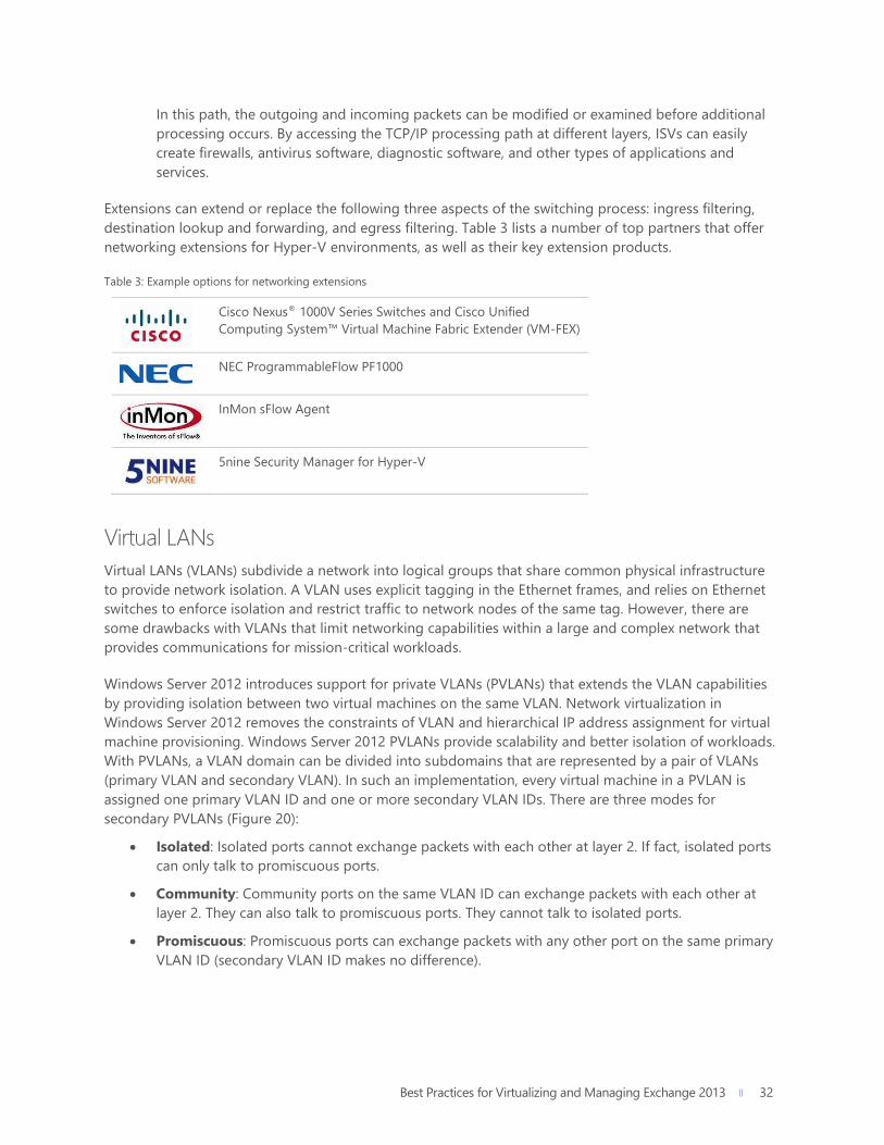
destination lookup and forwarding, and egress filtering. Table 3 lists a number of top partners that offer
networking extensions for Hyper-V environments, as well as their key extension products.
Table 3: Example options for networking extensions
Cisco Nexus® 1000V Series Switches and Cisco Unified
Computing System™ Virtual Machine Fabric Extender (VM-FEX)
NEC ProgrammableFlow PF1000
InMon sFlow Agent
5nine Security Manager for Hyper-V
Virtual LANs
Virtual LANs (VLANs) subdivide a network into logical groups that share common physical infrastructure
to provide network isolation. A VLAN uses explicit tagging in the Ethernet frames, and relies on Ethernet
switches to enforce isolation and restrict traffic to network nodes of the same tag. However, there are
some drawbacks with VLANs that limit networking capabilities within a large and complex network that
provides communications for mission-critical workloads.
Windows Server 2012 introduces support for private VLANs (PVLANs) that extends the VLAN capabilities
by providing isolation between two virtual machines on the same VLAN. Network virtualization in
Windows Server 2012 removes the constraints of VLAN and hierarchical IP address assignment for virtual
machine provisioning. Windows Server 2012 PVLANs provide scalability and better isolation of workloads.
With PVLANs, a VLAN domain can be divided into subdomains that are represented by a pair of VLANs
(primary VLAN and secondary VLAN). In such an implementation, every virtual machine in a PVLAN is
assigned one primary VLAN ID and one or more secondary VLAN IDs. There are three modes for
secondary PVLANs (Figure 20):
Isolated: Isolated ports cannot exchange packets with each other at layer 2. If fact, isolated ports
can only talk to promiscuous ports.
Community: Community ports on the same VLAN ID can exchange packets with each other at
layer 2. They can also talk to promiscuous ports. They cannot talk to isolated ports.
Promiscuous: Promiscuous ports can exchange packets with any other port on the same primary
VLAN ID (secondary VLAN ID makes no difference).

Best Practices for Virtualizing and Managing Exchange 2013 33
33
Figure 20: PVLAN in Windows Server 2012
Best Practices and Recommendations
VLANS and PVLANS can be a useful mechanism to isolate different Exchange infrastructures—for
instance, a service provider hosting multiple unrelated Exchange infrastructures. For customers
with VLAN constraints, PVLANS enable extra levels of isolation granularity within the same VLAN.
PVLANS can be configured through PowerShell.
Hardware Offloads – Dynamic Virtual Machine Queue
Virtual Machine Queue (VMQ) allows the host’s network adapter to pass DMA packets directly into
individual virtual machine memory stacks. Each virtual machine device buffer is assigned a VMQ, which
avoids needless packet copies and route lookups in the virtual switch. Essentially, VMQ allows the host’s
single network adapter to appear as multiple network adapters to the virtual machines, allowing each
virtual machine its own dedicated network adapter. The result is less data in the host’s buffers and an
overall performance improvement to I/O operations.
VMQ is a hardware virtualization technology for the efficient transfer of network traffic to a virtualized
host operating system. A VMQ-capable network adapter classifies incoming frames to be routed to a
receive queue based on filters that associate the queue with a virtual machine’s virtual network adapter.
These hardware queues may be affinitized to different CPUs, thereby enabling receive scaling on a per-
virtual network adapter basis.
Windows Server 2008 R2 allowed administrators to statically configure the number of processors available
to process interrupts for VMQ. Without VMQ, CPU 0 would run hot with increased network traffic. With

Best Practices for Virtualizing and Managing Exchange 2013 34
34
VMQ, the interrupts were spread across more processors. However, network load could vary over time. A
fixed number of processors may not have be suitable in all traffic regimes.
Windows Server 2012, on the other hand, dynamically distributes the processing of incoming network
traffic to host processors, based on processor use and network load. In times of heavy network load,
Dynamic VMQ (D-VMQ) automatically uses more processors. In times of light network load, D-VMQ
relinquishes those same processors. This helps to ensure that overall performance is optimized.
As shown in Figure 21, without the VMQ technology and RSS, the majority of network processing burdens
CPU 0 and ultimately limits the scale of the solution. With D-VMQ, processor cores are dynamically
assigned to distribute the workload.
Figure 21: Dynamically distributed workload with D-VMQ for Hyper-V
Best Practices and Recommendations
Some Intel multicore processors may use Intel Hyper-Threading Technology. When Hyper-
Threading Technology is enabled, the actual number of cores that are used by D-VMQ should be
half the total number of logical processors that are available in the system. This is because D-VMQ
spreads the processing across individual physical cores only, and it does not use hyper-threaded
sibling cores.
As an example, if the machine has an Intel processor with four physical cores and Hyper-Threading
Technology is enabled, it will show a total of eight logical processors. However, only four logical
processors are available to VMQ. (VMQ will use cores 0, 2, 4, and 6.)
VMQ provides improved networking performance for the management operating system as a
whole rather than for a specific virtual machine. For best results, treat queues as a scarce,
carefully managed resource. Because queues are allocated to virtual machines on a first-come,
first-served basis, making all virtual machines eligible for a queue may result in some queues being
given to virtual machines with light traffic instead of those with heavier traffic. Enable VMQ only
for those virtual machines with the heaviest inbound traffic. Because VMQ primarily improves
receive-side performance, providing queues for virtual machines that receive the most packets
offers the most benefit for overall performance of the management operating system.

Best Practices for Virtualizing and Managing Exchange 2013 35
35
Host Resiliency & VM Agility For mission-critical workloads, high availability and scalability are becoming increasingly important to
ensure that all users can access data and applications whenever they want. Windows Server 2012 Hyper-V
provides enhanced capabilities that help to ensure that Exchange 2013 workloads are agile, easy to
manage, and highly available at the hypervisor level.
Host Clustering This subsection discusses the key elements of host clustering, including failover clustering, Cluster Shared
Volumes, cluster networking, cluster-aware updating, virtual machine priority, virtual machine affinity, and
live migration.
Failover Clustering
Failover clustering allows you to connect physical machines (also called nodes) together to provide better
scalability and high availability. These clustered nodes work in such a way that if one or more of the active
nodes fail, the other nodes in the cluster begin to provide service (Figure 22). Clustered nodes are
continuously monitored to ensure that they are working properly. The nodes come to know each other’s
active status by using a heartbeat—a periodic signal between two directly connected machines.
Figure 22: Failover clustering—virtual machines fail over to Node 1 simultaneously

Best Practices for Virtualizing and Managing Exchange 2013 36
36
Best Practices and Recommendations
All hardware should be certified for Windows Server 2012, and the failover cluster solution should
pass all tests in the Validate a Configuration Wizard. For more information about validating a
failover cluster, see Validate Hardware for a Windows Server 2012 Failover Cluster.
Windows Server 2012 Hyper-V supports scaling clusters up to 64 nodes and 8,000 virtual machines per
cluster. Windows Server 2012 also provides Windows PowerShell cmdlets and a snap-in for Failover
Cluster Manager, which allows administrators to manage multiple clustered nodes.
The aim of failover clustering is to provide a resilient solution for workloads that are running on top of the
cluster. These could be clustered roles such as a file server, a DHCP server, or (as in the case of this paper)
a virtual machine. The Windows Server 2012 Failover Clustering capability provides resiliency for a number
of other roles or services. Additional information about this capability can be found here.
With virtual machines running on top of a Hyper-V cluster, should a Hyper-V cluster node fail, the virtual
machines also will experience downtime. However, the remaining cluster nodes immediately start working
to bring those virtual machines up again on an alternative node within the cluster—helping to ensure that
downtime is minimal and that administrator intervention is not required. This means that the workload—
in this case, Exchange 2013—has an extra level of resiliency when compared to a physical implementation.
The physical implementation requires the administrator to rely on only application-level resiliency, as
opposed to the dual layers of resiliency provided by a clustered Hyper-V implementation. This topic is
explored in more detail later in this paper.
Cluster Shared Volumes
With Cluster Shared Volumes (CSV), Windows Server 2012 provides shared storage resources for clustered
virtual machines. The CSV technology makes it easy to manage large numbers of LUNs in a failover
cluster. CSV allows simultaneous read-write permissions to the same NTFS-provisioned LUN disk from
multiple cluster nodes (Figure 23). Due to significant improvements in the CSV design in Windows Server
2012, Cluster Shared Volumes can perform an increased number of operations in direct I/O mode as
compared to previous versions of Windows Server. This feature also can be helpful while operating
workloads for failover, conducting live migration, or moving workloads. It allows workloads to share the
same volume without impacting the other workloads.
CSV provides better security for mission-critical data by supporting BitLocker Drive Encryption.
For decrypting data, CSV uses cluster name objects as identity for data decryption.
CSV provides continuous availability and scalability of file-based server storage for applications or
databases using the Scale-Out File Server feature.
CSV supports two types of snapshots, including application-consistent and crash-consistent
Volume Shadow Copy Service (VSS) snapshots.
CSV supports clustered VHD files for clustered workloads.

Best Practices for Virtualizing and Managing Exchange 2013 37
37
Figure 23: Cluster Shared Volumes
Best Practices and Recommendations
To provide high availability, use at least one separate CSV for Exchange 2013 databases/logs so
that each mailbox database copy of a particular mailbox database is stored on separate
infrastructure. In other words, in a four-copy deployment, a minimum of four CSVs should be used
to isolate database copies, and the storage and networking infrastructure used to provide access
to those CSVs should be completely isolated, as well.
The following guidelines are recommended for deploying a SAN with a failover cluster:
Confirm with the manufacturers and vendors whether the storage (including drivers,
firmware, and software) being used is compatible with failover clusters in Windows Server
2012. The Windows Server Catalog can be a useful source of guidance for this
information.
Isolate the LUN used for one set of cluster servers from all other servers through LUN
masking or zoning.
Use multipath I/O software for the highest level of redundancy and availability when
connecting your hosts to iSCSI or FC storage.

Best Practices for Virtualizing and Managing Exchange 2013 38
38
Cluster Networking
Before you begin to construct the failover cluster that will form the resilient backbone for key virtualized
workloads, it is important to ensure that the networking is optimally configured. Clusters, as a minimum,
require 2 x 1 GbE network adapters; however, for a traditional production Hyper-V failover cluster, it is
recommended that a greater number of adapters be used to provide increased performance, isolation,
and resiliency.
As a base level for customers using gigabit network adapters, 8 network adapters are recommended.
This provides the following:
2 teamed NICs used for Hyper-V host management and the cluster heartbeat.
2 teamed NICs used by a Hyper-V Extensible Switch to allow virtual machine communication.
2 teamed NICs used by Cluster Shared Volumes for traffic and communication.
2 teamed NICs used for live migration of virtual machines.
Moreover, if a customer is using iSCSI storage, an additional 2 NICs should be included for connectivity
from host to storage, and MPIO should be used instead of NIC Teaming. Alternatively, if the customer is
using SMB storage for the cluster, the hosts should have 2 NICs, but SMB Multichannel (or SMB Direct, if
RDMA is present) should be used to provide enhanced throughput and resiliency. So, in total, 10 NICs as a
minimum are mandated for a customer who:
Needs a cluster that uses Cluster Shared Volumes.
Wants to use live migration.
Requires resiliency at the NIC level.
These different networks can be combined onto fewer NICs, but isolation is recommended for optimal
performance.
Another option is to use fewer, higher bandwidth NICs, such as 2 x 10 GbE NICs that are combined into a
host-level team for an aggregated 20 Gb bandwidth. The question remains, however, how do you isolate
the different types of traffic (like CSV and live migration) on what essentially is a single NIC Team
presented at the host level? To solve this problem, you can use a converged approach.
Figure 24 provides a high-level example of this converged approach. Here, the Hyper-V cluster node has 2
x 10 GbE NICs, which are configured in a team. For the isolated networks that are required, you can create
virtual NICs (vNICs) for the host operating system. Each cluster node member uses a virtual network
adapter (for live migration, for CSV, for management, and so on) to connect to the single Hyper-V
Extensible Switch, which connects it to the physical network. Each tenant virtual machine is also connected
to the same Hyper-V Extensible Switch using a regular virtual network adapter. Windows Server 2012
Hyper-V virtual switch Quality of Service (QoS) is used to ensure that each traffic type (such as live
migration, cluster, management, and tenant) has a predictable amount of bandwidth available. Traffic
isolation is enabled by 802.1q VLAN tagging so that host traffic is not visible to the tenants. Hyper-V
virtual switch port ACLs also can be used for more granular access control at the network level.

Best Practices for Virtualizing and Managing Exchange 2013 39
39
Figure 24: High-level overview of cluster member converged networking configuration
This converged approach can significantly reduce the number of physical NICs required in each host and,
subsequently, the number of overall switch ports. Yet at the same time, the approach provides resiliency
and high levels of bandwidth for key virtual machines and workloads. More information about converged
infrastructure options can be found here on TechNet.
Cluster-Aware Updating
In the past, it has been a challenging task for administrators to appropriately update and patch failover
clusters. The Cluster-Aware Updating (CAU) feature in Windows Server 2012 simplifies this task. CAU
facilitates automated maintenance of cluster nodes/servers. Automating cluster nodes makes the server
maintenance process in a cluster faster, easier, more reliable, and more consistent with less downtime.
CAU puts each cluster node in maintenance mode, applies required updates/patches, and restores the
node to be used again. At a high level, CAU performs the following steps:27
Puts a node of the cluster in maintenance mode and takes it offline transparently.
Moves clustered roles off the node.
Installs the updates or patches, and any dependent updates.
Performs a restart, if needed.
Brings the node back online and out of maintenance mode.
Restores clustered roles on the node.
Moves to the next node and updates/patches it in the same manner.
This increases the availability of servers during the update and patching process in both environments
(virtualized and non-virtualized). It also helps to maintain the security and performance of servers in the
cluster. Administrators use the Cluster-Aware Updating Wizard for automating the update of a failover
cluster (Figure 25).
Best Practices for Virtualizing and Managing Exchange 2013 40
40
Figure 25: Cluster-Aware Updating Wizard
CAU can perform the cluster updating process in two different modes: self-updating mode and remote-
updating mode. In self-updating mode, the CAU clustered role is configured as a workload on the failover
cluster that is to be updated. In remote-updating mode, a remote computer running Windows Server
2012 or Windows 8 is configured with the CAU clustered role. This remote computer is also called the
Update Coordinator and is not part of the cluster that is updating.
Note that for many clustered roles in a cluster, the automatic updating process triggers a planned failover,
which, in turn, can cause a service interruption for a very short time (transient).28
Best Practices and Recommendations
Use the CAU feature with continuously available cluster workloads in Windows Server 2012 to
perform updates on clusters with no impact on service availability. Examples of continuously
available cluster workloads in Windows Server 2012 are file servers (file server with SMB
Transparent Failover) and Hyper-V virtual machines with live migration. With CAU, virtualized
Exchange Servers experience no downtime, even though underlying hosts are being patched and
potentially taken offline for maintenance.
Create Updating Run Profiles for different classes of failover clusters, and store and manage them
on a centralized file share. This ensures that the CAU deployments consistently apply updates to
the clusters throughout the IT organization (even across different departments, line-of-business
areas, or administrators).

Best Practices for Virtualizing and Managing Exchange 2013 41
41
CAU supports an extensible architecture that helps to update the cluster node with node-updating tools
and software updates that are not available from Microsoft or through Windows Update or Microsoft
Update. Examples include custom software installers, updates for non-Microsoft device drivers, and
network adapter/HBA firmware updating tools. This is beneficial for publishers who want to coordinate
the installation of non-Microsoft software updates.
Virtual Machine Priority
IT administrators can configure availability options for virtual machines running on Hyper-V host clusters.
An administrator sets priority for the virtual machines in a host cluster, which the host cluster uses to
identify the high-priority virtual machines and give them first preference. This ensures that high-priority
virtual machines are allocated memory and other resources first upon failover.29
In Windows Server 2012, administrators can configure availability options/settings to provide improved
and efficient allocation of cluster resources (such as when starting or maintaining nodes) in large physical
clusters and Hyper-V failover clusters. The availability options for managing clustered virtual machines
and other clustered roles include the following:30
Priority settings: This option can be applied to all clustered roles, including clustered virtual
machines. A virtual machine can be set to high priority, medium priority, low priority, or No Auto
Start. By default, every virtual machine is set to medium priority. Clustered roles with higher
priority are started and placed on nodes before those with lower priority. If a No Auto Start
priority is assigned, the role does not come online automatically after it fails, which keeps
resources available so other roles can start.
Preemption of virtual machines based on priority: This option can be applied to clustered
virtual machines. In case of a node failure, if the high-priority virtual machines do not have the
necessary memory and other resources to start, the lower priority virtual machines are taken
offline to free up resources. When necessary, preemption starts with the lowest priority virtual
machines and continues to higher priority virtual machines. Virtual machines that are preempted
are later restarted in priority order.
Best Practices and Recommendations
In case of failover, virtualized domain controllers, along with other high-priority workloads like
Exchange 2013 virtual machines, should be given the highest priority to start first.
Virtual Machine Affinity
The Virtual Machine Affinity rules in Windows Server 2012 allow administrators to configure partnered
virtual machines to migrate simultaneously at failover. For example, imagine two machines are partnered:
One virtual machine has front-end applications and the other has a back-end database.
It can also be specified that two particular virtual machines cannot coexist on the same node in a failover
scenario. This is the Virtual Machine Anti-Affinity rule. In this case, Windows Server 2012 Hyper-V migrates
the partnered virtual machines to different nodes to help mitigate a failure. For example, domain
Best Practices for Virtualizing and Managing Exchange 2013 42
42
controllers running on the same Hyper-V host can be migrated to different nodes to prevent loss of the
domain in case of failure.
Windows Server 2012 Hyper-V provides a cluster group property called AntiAffinityClassNames that can
be applied to any virtual machine in the Hyper-V cluster group. This property allows preferences to be set
to keep a virtual machine off the same node as other virtual machines of a similar kind.
Best Practices and Recommendations
Use Virtual Machine Anti-Affinity rules to keep related Exchange 2013 virtual machines apart on
hosts within a Hyper-V Cluster. This ensures that if any host is lost, whole Exchange deployments
are not taken down as a result.
Live Migration
Previous sections of this paper have focused on the failover cluster, which provides the solid, resilient
foundation for ensuring workloads like virtual machines are as continuously available as possible. Further,
with a failover cluster in place, other key capabilities that provide solutions for planned maintenance are
unlocked. Live migration is one of these capabilities.
Live migration is a process where running workloads can be moved from a source server to a destination
server without impacting the availability of running business applications or critical data. While migrating
live virtual machines, there are two major concerns: outage of applications or data, and prevention of data
loss.
Windows Server 2012 with Hyper-V provides a better way to migrate running virtual machines from one
physical server to another without hampering business availability. Hyper-V 2012 with the enhanced Live
Migration feature allows you to execute the live migration of multiple workloads at the same time, all
without downtime. During the migration process of any workload, no additional configuration changes
are required on the guest operating system.
Windows Server 2012 with Hyper-V efficiently uses the available network bandwidth on
designated Live Migration networks to reduce the time taken for the process.
Hyper-V now offers functionality to migrate multiple virtualized Exchange 2013 servers
simultaneously.
For migrating virtual machines, Hyper-V sets up a TCP connection between source and destination hosts
to transfer virtual machine configurations. The memory assigned to the migrating virtual machine is
transferred over the network to the destination virtual machine. Hyper-V keeps track of the memory
pages being modified during the transfer from the source to the destination server. Once all the modified
pages are copied completely to the destination server, Hyper-V takes care of the migration of any
associated virtual hard disk files or connectivity to physical storage attached through a virtual FC adapter.
After completing all stages of migration, Hyper-V brings up the new destination virtual machine, with no
downtime to the workload itself (Figure 26).

Best Practices for Virtualizing and Managing Exchange 2013 43
43
Figure 26: Live migration with Hyper-V
In addition to improvements made with the Live Migration feature, Windows Server 2012 now allows the
live migration of virtual machine storage—independent of the virtual machine itself and without any
downtime. This is known as live storage migration and can be initiated using the Hyper-V Manager
console, Failover Cluster console, Microsoft System Center Virtual Machine Manager (SCVMM) console, or
PowerShell. This capability can be used in several scenarios, including the need to redistribute virtual
machine storage when disk space runs low or the need to perform maintenance on underlying storage
without disrupting the virtual machine. Live storage migration for .vhd and .vhdx disks can be performed
on standalone Hyper-V servers and clustered Hyper-V servers. Live storage migrations cannot be used
with pass-through disks.
Windows Server 2012 also implements shared-nothing live migration, which helps in migrating virtual
machines using just a network cable without any downtime. Shared-nothing live migration works in
conjunction with live migration and live storage migration. First the storage is live migrated. Once the live
storage migration completes, the state of the virtual machines is copied and synchronized between the
source and destination servers over the network.

Best Practices for Virtualizing and Managing Exchange 2013 44
44
Virtual Machine Configuration In addition to configuring and establishing the host server as a virtualization server with Hyper-V, it is
important to design detailed architecture and system specifications for building virtual machines for
expected workloads. It is also necessary to plan for needed resources for the virtual machines. The
number of virtual machines you can run on any individual server depends on the server’s hardware
configuration and the anticipated workloads.
General Supportability Before you begin to virtualize Exchange 2013, it is important to understand the general supportability of
the products, as well as what combinations of products will ensure that if you encounter an issue,
Microsoft Customer Support Services will be able to support you through the process fully.
Best Practices and Recommendations
While all efforts have been made to ensure the accuracy of this supported guidance, over
time, supported configurations may change. Please refer to the Exchange Virtualization
documentation on TechNet for definitive, up to date clarification
Hypervisor support for running Exchange 2013 in a virtual machine:
Windows Server 2008 R2 SP1 Hyper-V | Hyper-V Server 2008 R2 SP1
Windows Server 2012 Hyper-V and later | Hyper-V Server 2012 and later
Any third-party hypervisor certified under the Server Virtualization Validation Program
Exchange 2013 is not supported on:
Virtual Machines running on Windows Azure Infrastructure Services
Guest operating system that is running Exchange 2013 roles must be either:
Windows Server 2008 R2 SP1
Windows Server 2012 or 2012 R2
Microsoft Assessment and Planning Toolkit Consolidating an application’s workloads can help to improve the efficiency and agility of that application.
It also can provide better control and flexibility over computing resources in terms of their placement,
sizing, and overall utilization. Consolidating Exchange workloads requires proper planning because every
element of a virtual Exchange Server deployment should comply with Exchange licensing requirements. It
is also important to account for other software products that are prerequisites for installing Exchange
Server, including Windows Server.

Best Practices for Virtualizing and Managing Exchange 2013 45
45
The Microsoft Assessment and Planning (MAP) toolkit can help organizations to properly plan their
Exchange 2013 virtualization, speed up migration to a virtual environment (Hyper-V), and start realizing
the benefits of virtualization. The MAP toolkit provides a complete software tracker that collects and
reports client access and server usage information of Exchange Server deployments. The reports and
proposals provided by the MAP toolkit include a server consolidation report, server consolidation
proposal, workload discovery report, and cost savings and ROI assessment. The information provided in
these reports and proposals can be used to consolidate Exchange workloads, better utilize hardware
resources, and determine licensing needs.
Exchange 2013 Server Role Requirements Calculator Before an Exchange 2013 deployment, whether physical or virtual, accurate capacity planning and sizing is
imperative for success. The Exchange Product Team has produced a significant amount of information and
guidance to help with the sizing of different Exchange 2013 roles. Using this guidance in conjunction with
the best practices and recommendations in this paper can help you to better plan and deploy an
Exchange 2013 infrastructure.
Best Practices and Recommendations
For detailed sizing guidance for Exchange 2013, refer to Sizing Exchange 2013 Deployments on
the Exchange Team Blog. In addition, the Exchange 2013 Server Role Requirements Calculator can
help to accelerate the sizing decisions for Exchange 2013 deployments across both physical and
virtual infrastructures.
Exchange 2013 Virtual Machine CPU Considerations This subsection discusses Non-Uniform Memory Access from the virtual machine perspective.
Best Practices and Recommendations
It is important to note that Exchange 2013 as an application is not NUMA-aware. However,
when sizing a virtual machine, you must still understand the underlying physical NUMA topology
to ensure the highest levels of performance at the guest level.
Non-Uniform Memory Access – Virtual Machine Perspective
In Windows Server 2012, NUMA is extended to the virtual environment (virtual NUMA) by making virtual
NUMA topology available to the guest operating systems. High-performance applications support NUMA
and use the computer’s NUMA topology to increase performance by considering NUMA when scheduling
threads or allocating memory. Therefore, by reflecting the underlying NUMA topology into virtual
machines, organizations can maximize performance gains from running NUMA-aware workloads in
virtualized farm environments on NUMA. Exchange 2013 is not a NUMA-aware workload, but it
appreciates NUMA to the same level as any other non-NUMA-aware application.

Best Practices for Virtualizing and Managing Exchange 2013 46
46
To identify and adapt to the virtual NUMA topology within the virtual machines, the NUMA-aware guest
operating system and applications use their inherent NUMA performance optimizations. In this way with
Windows Server 2012 Hyper-V, the default virtual NUMA topology is optimized to match the NUMA
topology of the host/physical computer, as shown in Figure 27.31
Figure 27: Guest NUMA topology by default matching host NUMA topology
The best practices below provide more guidance around managing varying CPU demand, reducing
overhead on the CPU, and optimizing processor performance for Exchange workloads.32, 33
Best Practices and Recommendations
Hyper-V publishes performance counters like Performance Monitor (Perfmon.exe) and
Logman.exe. These performance counters help to characterize the behavior of the virtualization
server and report resource usage. To measure CPU usage of the physical host, use the Hyper-V
Hypervisor Logical Processor performance counters. The Performance Tuning Guidelines for
Windows Server 2012 contain the list of available performance counters.
Do not oversubscribe the CPU for any virtual machine that you use in an Exchange 2013
infrastructure. Use a VP:LP ratio of 1:1 for optimum performance, but 2:1 is supported.
For any virtual machine that is running Exchange 2013 roles, detailed and accurate capacity
planning and sizing should be performed. This is to determine the correct amount of
processors/cores or, in this case, the minimum number of virtual CPUs that should be assigned to
the Exchange virtual machine. This value should be based on published guidance from the
Exchange team, such as that found on TechNet or the Exchange Team Blog on Sizing. The
Exchange 2013 Server Role Requirements Calculator also provides helpful guidance.
Although Exchange 2013 is not NUMA-aware, it takes advantage of the Windows scheduler
algorithms that keep threads isolated to particular NUMA nodes; however, Exchange 2013
does not use NUMA topology information.

Best Practices for Virtualizing and Managing Exchange 2013 47
47
Best Practices and Recommendations
Crossing the NUMA boundary can reduce virtual performance by as much as 8 percent. Therefore,
configure a virtual machine to use resources from a single NUMA node.34 For Exchange Server,
make sure that allocated memory is equal to or smaller than a NUMA boundary.
While setting NUMA node preferences (NUMA node balancing) for virtual machines, ensure that
all virtual machines are not assigned to the same NUMA node. If this happens, the virtual
machines may not get enough CPU time or local memory from the assigned NUMA node.35
By default, a virtual machine gets its preferred NUMA node every time it runs. However, in due
course, an imbalance in the assignment of NUMA nodes to the virtual machines may occur. This
may happen because each virtual machine has ad hoc memory requirements or because the
virtual machines can be started in any order. Therefore, we recommend that you use Perfmon to
check the NUMA node preference settings for each running virtual machine. The settings can be
checked with the following: \Hyper-V VM Vid Partition (*)\ NumaNodeIndex counter.
Perform NUMA node balancing to automatically change NUMA node assignments, depending on
the requirements of the running virtual machines.
Identify and categorize virtual machines based on the intensity of the loads they bear (high
intensity and low intensity). Then set weights and reserves on the virtual processors accordingly. In
this way, you can ensure that a large amount of the CPU cycle is available for virtual
machines/virtual processors having high-intensity loads.
Install the latest virtual machine Integration Services in each supported guest virtual machine.
Virtual machine Integration Services can help to improve I/O throughput and decrease overall CPU
usage of guests. This is because it includes enlightened drivers for Hyper-V-specific I/O devices
that reduce CPU overhead for I/O.
Exchange 2013 Virtual Machine Memory Considerations For memory in a virtualized environment, better performance and enhanced support are essential
considerations. You must be able to both quickly allocate memory to virtual machines depending on their
requirements (peak and off-peak loads) and ensure that the memory is not wasted. New enhancements in
Windows Server 2012 help to optimize the utilization of memory allocated to virtual machines.36 One of
these enhancements is known as Dynamic Memory, which allows Hyper-V to intelligently give and take
memory from a virtual machine while it is running, depending on the demand within that virtual machine
at a given time.

Best Practices for Virtualizing and Managing Exchange 2013 48
48
Best Practices and Recommendations
Microsoft does not support Dynamic Memory for virtual machines that run any of the
Exchange 2013 roles. Exchange 2013 uses in-memory data caching to provide better
performance and faster I/O operations. To achieve this, Exchange 2013 needs a substantial
amount of memory at all times and full control over the memory. If Exchange 2013 does not have
full control of the memory allocated to the physical or virtual machines on which it is running,
degraded system performance and a poor client experience can result. Therefore, Dynamic
Memory is not supported for Exchange 2013.
Dynamic Memory
While not supported with virtual machines running any Exchange 2013 roles, Dynamic Memory can
still provide a valuable and effective solution for optimizing memory usage for other virtualized
workloads. Virtual machines with Dynamic Memory enabled can coexist without issue on hosts with
other virtual machines that have Dynamic Memory disabled. Earlier versions of Hyper-V only allowed
administrators to assign a fixed amount of physical memory to a virtual machine on the host machine.
Once the memory was assigned, it was not possible to change the memory for that particular virtual
machine during its run state.37, 38 To overcome this problem, Microsoft introduced the concept of Dynamic
Memory in Windows Server 2008 R2 SP1.
With Windows Server 2012, Microsoft has enhanced the Dynamic Memory feature to provide increased
agility around how memory is allocated and managed between virtual machines running on a host.
Dynamic Memory in Windows Server 2012 has introduced two key new enhancements: minimum memory
and Hyper-V smart paging.
Minimum Memory
Minimum memory allows Hyper-V in Windows Server 2012 to reclaim the unused memory from virtual
machines. This results in increased virtual machine consolidation. However, there can be a limitation to
this feature. If you must restart one virtual machine and it has less memory than required for its startup
memory, Hyper-V needs additional memory to restart the machine. Yet, Hyper-V may not always have
additional memory available. Such a situation results in a virtual machine start failure. To overcome this
situation, Dynamic Memory in Windows Server 2012 has introduced Hyper-V Smart Paging.
Hyper-V Smart Paging
Hyper-V Smart Paging is a memory management technique that is used to cover the gap between
minimum memory and startup memory, enabling reliable restart of virtual machines (Figure 28). It uses
disk resources as additional, temporary memory when more physical memory is required to restart a
virtual machine than is currently available.39, 40

Best Practices for Virtualizing and Managing Exchange 2013 49
49
Figure 28: Hyper-V Smart Paging
Hyper-V Smart Paging can lead to some performance degradation due to slower disk access speeds.
Therefore, to ensure that the performance impact of Smart Paging is minimized, this feature is used only
when all of the following are true:
The virtual machine is being restarted.
No physical memory is available.
No memory can be reclaimed from other virtual machines that are running on the host.
Memory ballooning: Memory ballooning is a technique used to further reduce the performance impact
of Hyper-V Smart Paging. Once the virtual machine is restarted and the need for memory is less than the
startup memory, Hyper-V can stop using Smart Paging. Therefore, Hyper-V removes the temporary
memory from the virtual machine by coordinating with Dynamic Memory components inside the guest (a
process sometimes referred to as ballooning). With this technique, use of Hyper-V Smart Paging is
temporary and is not expected to be longer than 10 minutes. Figure 29 shows Hyper-V removing memory
from the virtual machine after it completes the startup process.41
Figure 29: Removing paged memory after virtual machine restart

Best Practices for Virtualizing and Managing Exchange 2013 50
50
The best practices below provide more guidance around planning and managing memory for virtual
machines running Exchange 2013 workloads.42, 43, 44
Best Practices and Recommendations
For any virtual machine that is running Exchange 2013 roles, detailed and accurate capacity
planning and sizing should be performed to determine the correct amount of minimum memory
that should be assigned to the Exchange virtual machine. This value should be based on published
guidance from the Exchange team, as well as the use of the Exchange 2013 Server Role
Requirements Calculator. The following figures are the absolute smallest supported amounts of
memory required for an Exchange 2013 deployment:
Mailbox: 8 GB minimum
Client Access: 4 GB minimum
Mailbox and Client Access combined: 8 GB minimum
The page file size minimum and maximum must be set to the operating system’s RAM plus 10 MB.
In environments where performance is critical, use SSD for Smart Paging.
Exchange 2013 Virtual Machine Storage Considerations With an optimal configuration for both CPU and memory, you need to ensure that the underlying disk
subsystem is also optimally configured for the Exchange 2013 workload. This subsection discusses two key
storage considerations for Exchange 2013: virtual disks and guest storage.
Best Practices and Recommendations
Provide at least 30 GB of space on the drive where you will install Exchange.
Add an additional 500 MB of available disk space for each Unified Messaging (UM) language pack
that you plan to install.
Add 200 MB of available disk space on the system drive.
Use a hard disk with at least 500 MB of free space to store the message queue database, which can
be co-located on the system drive, assuming you have accurately planned for enough space and
I/O throughput.
Virtual Disks
When considering virtual disks, it is important to know the capabilities and limitations of the different
types. Discussed below are the VHDX file format, dynamically expanding VHDX versus fixed-size VHDX,
and virtual IDE versus virtual SCS.

Best Practices for Virtualizing and Managing Exchange 2013 51
51
VHDX File Format
Hyper-V in Windows Server 2012 introduces VHDX, a new version of the virtual hard disk format that is
designed to handle current and future workloads. VHDX has a much larger storage capacity than the older
VHD format. It also provides protection from data corruption during power failures and optimizes
structural alignments to prevent performance degradation on new, large sector physical disks. The main
features of the VHDX format are as follows:
Support for virtual hard disk storage capacity of up to 64 TB.
Protection against data corruption during power failures by logging updates to the VHDX
metadata structures.
Improved alignment of the virtual hard disk format to work well on large sector disks.
Larger block sizes for dynamic and differencing disks, which allows these disks to attune to the
needs of the workload.
A 4-KB logical sector virtual disk that allows for increased performance when used by applications
and workloads that are designed for 4-KB sectors.
The ability to store custom metadata about a file that the user might want to record, such as
operating system version or patches applied.
Efficiency in representing data (also known as trim), which results in smaller file size and allows
the underlying physical storage device to reclaim unused space. (Trim requires physical disks
directly attached to a virtual machine or SCSI disks, and trim-compatible hardware.)
Best Practices and Recommendations
When you create virtual machines on Windows Server 2012 Hyper-V, the VHDX file format should
be the default choice. While not compatible with previous versions of Hyper-V, its capacity
advantage, better alignment with underlying storage, and stronger protection against corruption
make VHDX an ideal choice for mission-critical workloads like Exchange 2013.
Dynamically Expanding VHDX vs. Fixed-Size VHDX
Fixed-size VHDX uses the full amount of space specified during virtual hard disk creation. However, the
size of a fixed-size VHDX can be increased while the virtual machine is offline by using Hyper-V Manager
or running a PowerShell script. Note that reducing the size is not supported. Fixed-size VHDX delivers
near native-to-physical performance and slightly higher performance than dynamically expanding VHDX
files.
During virtual hard disk creation, dynamically expanding VHDX files only consume physical space based
on their actual contents. For instance, an administrator could create a dynamically expanding VHDX with a
maximum size of 127 GB. Upon creation, the actual physical size of the VHDX file may only be a few MB,
but as files are added to the VHDX inside the guest operating system, the size of the VHDX file in the
physical world grows accordingly. The guest operating system always sees the maximum size that the
administrator chose upon creation.

Best Practices for Virtualizing and Managing Exchange 2013 52
52
Best Practices and Recommendations
Each Exchange guest machine must be allocated sufficient storage space on the host machine for
the fixed disk that contains the guest's operating system, any temporary memory storage files in
use, and related virtual machine files that are hosted on the host machine. In addition, for each
Exchange guest machine, you must also allocate sufficient storage for the message queues and
sufficient storage for the databases and log files on Mailbox servers.
The storage used by the Exchange guest machine for storage of Exchange data (for example,
mailbox databases and transport queues) can be virtual storage of a fixed size (for example, fixed
virtual hard disks (VHD or VHDX) in a Hyper-V environment), dynamic virtual storage when using
VHDX files with Hyper-V, SCSI pass-through storage, or Internet SCSI (iSCSI) storage. Pass-through
storage is storage that's configured at the host level and dedicated to one guest machine. All
storage used by an Exchange guest machine for storage of Exchange data must be block-level
storage because Exchange 2013 doesn't support the use of network attached storage (NAS)
volumes, other than in the SMB 3.0 scenario outlined below. Also, NAS storage that's presented to
the guest as block-level storage via the hypervisor isn't supported.
Fixed or dynamic virtual disks may be stored on SMB 3.0 files that are backed by block-level storage
if the guest machine is running on Windows Server 2012 Hyper-V (or a later version of Hyper-V).
The only supported usage of SMB 3.0 file shares is for storage of fixed or dynamic virtual disks.
Such file shares can't be used for direct storage of Exchange data. When using SMB 3.0 file shares
to store fixed or dynamic virtual disks, the storage backing the file share should be configured for
high availability to ensure the best possible availability of the Exchange service.
Storage used by Exchange should be hosted in disk spindles that are separate from the storage
that's hosting the guest virtual machine's operating system
To reduce disk contention, do not store system files on hard drives dedicated to storing virtual
machines.
Do not use snapshots for the virtual machines in an Exchange 2013 production environment. When
you create a snapshot, Hyper-V creates a new secondary drive for the virtual machines. Write
operations occur on the new drive, and read operations occur on both drives, resulting in reduced
performance.
Be aware of underlying disk read/write contention between different virtual machines and their
virtual hard disks.
Virtual IDE vs. Virtual SCSI
Virtual machines can be configured to use virtual IDE device controllers or virtual SCSI device controllers
to connect virtual storage. When a virtual machine starts, the virtual IDE controller is used with a boot
VHD/x file because the virtual SCSI disk requires a driver to be present during boot-up. This driver is only
present when booted into the operating system. IDE is limited to 3 connected disks. (One port is retained
for the DVD drive, which is required for updating the integration components.) Virtual SCSI, on the other

Best Practices for Virtualizing and Managing Exchange 2013 53
53
hand, can have 64 connected disks per controller and 4 controllers per virtual machine, giving a total of
256 virtual SCSI disks per virtual machine. Virtual SCSI also supports hot-add/removal of disks, whereas
virtual IDE disks do not.
Best Practices and Recommendations
The virtual IDE controller must be used for booting the virtual machine; however, all other drives
should be attached to the virtual SCSI controller. This ensures optimal performance, as well as the
greatest flexibility. Each virtual machine has a single virtual SCSI controller by default, but three
more can be added while the virtual machine is offline.
Guest Storage
In addition to presenting VHD or VHDX files to Exchange 2013 virtual machines, administrators can
choose to connect the guest operating system of an Exchange virtual machine directly to existing storage
investments. Two methods provided in Windows Server 2012 Hyper-V are In-Guest iSCSI and Virtual Fibre
Channel.
In-Guest iSCSI
Deploying an Exchange 2013 virtual machine on iSCSI storage provides a more cost-effective solution for
enterprise-level virtual machine installations than an equivalent Fibre Channel solution. Instead of using
virtual disks (such as the VHD or VHDX files discussed earlier) and placing them on the iSCSI LUNS
presented to the host, the administrator can choose to bypass the host and connect the virtual machines
directly to the iSCSI array itself. The iSCSI target, which is part of the storage array, provides storage to the
Exchange 2013 virtual machine directly over the virtual machine’s network adapters. The Exchange virtual
machine uses the in-box iSCSI initiator inside the Windows Server guest operating system to consume the
storage over a vNIC that has connectivity on the iSCSI storage network. The respective Exchange Servers
can therefore store information, logs, and other critical data directly on iSCSI disk volumes.
To enact this approach, the administrator must create dedicated Hyper-V virtual switches and bind them
to appropriate physical NICs in the hosts. This ensures that the virtual machines can communicate with
the iSCSI storage on the appropriate network/VLAN. After configuration, the administrator must use the
guest operating system IQN from the iSCSI initiator to present the appropriate LUNS directly to the virtual
machine over the virtual networks. In addition, vNIC features like jumbo frames and some other offload
capabilities can help to increase performance and throughput over the network. It is important to note
that if you intend to run the virtual machine with In-Guest iSCSI on top of a Hyper-V cluster, all cluster
nodes must have the same iSCSI virtual switches created on the hosts to ensure that when the virtual
machine migrates around the cluster, connectivity to the underlying storage is not lost.
For resiliency, the administrator may want to use multiple vNICs to connect the virtual machine to the
iSCSI SAN. If this is the case, it is important to enable and configure MPIO, as discussed earlier, to ensure
optimal performance and resiliency.

Best Practices for Virtualizing and Managing Exchange 2013 54
54
Virtual Fibre Channel
In a similar way to iSCSI, Virtual Fibre Channel for Hyper-V helps to connect to FC storage from within a
virtual machine, bypassing the host’s operating system. Virtual FC for Hyper-V provides direct SAN access
from the guest operating system by using standard World Wide Node Names (WWNN) and Worldwide
Port Names (WWPN) associated with a virtual machine. Virtual FC for Hyper-V also helps to run the
Failover Clustering feature inside the guest operating system of a virtual machine connected to the
underlying, shared FC storage.
For virtualizing Exchange 2013, Virtual FC for Hyper-V allows you to use existing FC investments to drive
the highest levels of storage performance access, while also retaining support for virtual machine live
migration and MPIO.
Exchange 2013 Virtual Machine Network Considerations Networking and network access are critical to the success of an Exchange deployment. Windows Server
2012 Hyper-V provides a number of capabilities, technologies, and features that an administrator can use
to drive the highest levels of networking performance for the virtualized Exchange infrastructure.
Legacy versus Synthetic Virtual Network Adapters
When creating a virtual machine, the administrator has two choices for virtual network adapters (or
vNICs): legacy or synthetic. A legacy adapter emulates an Intel 21140-based PCI Fast Ethernet Adapter,
which results in a lower data transfer than the network adapter. Legacy network adapters (also known as
emulated NIC drivers) should only be used when booting a virtual machine in the Pre-Boot Execution
Environment (PXE) or when installing guest operating systems that are not Hyper-V-aware.
Synthetic adapters are the preferred option for most virtual machine configurations because they use a
dedicated VMBus to communicate between the virtual NIC and the physical NIC. This results in reduced
CPU cycles, as well as much lower hypervisor/guest transitions per operation. The driver for the synthetic
adapter is included with the Integration Services that are installed with the Windows Server 2012 guest
operating system.
Best Practices and Recommendations
From an Exchange 2013 perspective, there is no reason to use the Legacy vNIC. At minimum,
customers should use the default synthetic vNIC to drive higher levels of performance. In addition,
should the physical network card support them, the administrator should take advantage of a
number of the NIC offloads that can further increase performance.
Single Root I/O Virtualization
The Single Root I/O Virtualization standard was introduced by the PCI-SIG, the special interest group that
owns and manages PCI specifications as open industry standards. SR-IOV helps to virtualize demanding
workloads like Exchange 2013 that require higher network and I/O performance. It does so by enabling
virtual machines to perform I/O directly to the physical network adapter by bypassing the root partition.

Best Practices for Virtualizing and Managing Exchange 2013 55
55
In Windows Server 2012, SR-IOV can be deployed in conjunction with key capabilities such as live
migration to enable high network performance with availability.
SR-IOV provides extensions to PCI Express (PCIe) devices like network adapters to separate access to its
resources among various PCIe hardware functions. Two of these functions are PCIe Physical Function (PF)
and PCIe Virtual Functions (VFs):
PCIe Physical Function is the primary function of the device and advertises its SR-IOV
capabilities. The PF is associated with the Hyper-V parent partition in a virtualized environment.
PCIe Virtual Functions are associated with the PF of the device. A VF shares one or more physical
resources, such as memory and network ports, with the PF and other VFs on the device. Each VF is
associated with a Hyper-V child partition in a virtualized environment.
Using Hyper-V Manager, you can enable SR-IOV in Windows Server 2012 when you create a virtual switch
(Figure 30).45
Figure 30: Enabling SR-IOV in the Virtual Switch Properties window

Best Practices for Virtualizing and Managing Exchange 2013 56
56
Once the virtual switch is created, SR-IOV should also be enabled while configuring a virtual machine in
the Hardware Acceleration node (Figure 31).
Figure 31: Enabling SR-IOV in the Virtual Machine Properties window
Figure 32 shows how SR-IOV attaches a physical NIC to an Exchange 2013 virtual machine. This provides
the Exchange 2013 virtual machine with a more direct path to the underlying physical network adapter,
increasing performance and reducing latency—both of which are important considerations for the
Exchange 2013 workload.
Figure 32: SR-IOV support in Hyper-V

Best Practices for Virtualizing and Managing Exchange 2013 57
57
With the virtual machine now attached to the physical NIC through the VF, does this mean that this
particular virtual machine cannot be live migrated to another physical host? The answer is no—the virtual
machine is still free to be live migrated, with no downtime, to another available node in the cluster. This
helps to ensure that Hyper-V in Windows Server 2012 not only provides high levels of performance, but
also does so without sacrificing agility.
SR-IOV automatically fails over the network traffic from the VF to the synthetic data path of the Hyper-V
virtual machine. The transition between the VF and synthetic data paths occurs with minimum loss of
packets and prevents the loss of TCP connections. Whenever there is a state transition that requires the
hardware state to be saved, the VF is removed from the virtual machine beforehand, falling back to the
synthetic path. Once the VF is removed, any operation necessary can be performed on the virtual machine
because it is a complete software-based container at that point.
The Hyper-V child partition is being live migrated to a different host at this stage. Once the operation has
been completed, assuming hardware resources are available and other dependencies are met, the VF is
returned back to the virtual machine. This solves the problem of saving the hardware state of the virtual
machine and helps to ensure that workloads receive the highest levels of performance. The high-level
process is outlined below.46, 47, 48 Note that throughout this process, the Exchange virtual machine always
has connectivity.
SR-IOV is enabled for the Exchange virtual machine, and its VF is assigned. Traffic flows down the
VF path, not the software stack.
When live migration starts, connectivity is failed over to the synthetic path, and the VF is removed.
At this point, live migration of the virtual machine takes place from source to destination. (Traffic
is now travelling via the synthetic software stack.)
Upon arrival, the VF is reassigned and traffic now passes via the VF. Alternatively, if the virtual
machine has been migrated to a new host that does not have SR-IOV-capable hardware, the
network traffic continues to operate along the synthetic software stack.
If the Exchange virtual machine is configured to use SR-IOV, but the guest operating system does not
support it, SR-IOV VFs are not allocated to the virtual machine. We recommend that you disable SR-IOV
on all virtual machines that run guest operating systems that do not support SR-IOV.49
Best Practices and Recommendations
SR-IOV can provide the highest levels of networking performance for virtualized Exchange
virtual machines. Check with your hardware vendor for support because there may be a BIOS and
firmware update required to enable SR-IOV.
QoS Bandwidth Management
Quality of Service is a prioritization technique that gives the ability to cost effectively manage network
traffic and enhance user experiences in enterprise environments. QoS allows you to meet the service
requirements of a workload or application in an Exchange environment by measuring network bandwidth,
detecting changing network conditions (such as congestion or availability of bandwidth), and prioritizing
or throttling network traffic. QoS provides features like bandwidth management, classification and
tagging, priority-based flow control, policy-based QoS, and Hyper-V QoS.50

Best Practices for Virtualizing and Managing Exchange 2013 58
58
For Hyper-V virtual machines specifically, QoS bandwidth management helps to set a throttling rate for a
workload like Exchange 2013. Minimum Bandwidth and Maximum Bandwidth enable organizations to
enforce predictable network throughput for the Exchange workload. Apart from bandwidth management,
organizations can prioritize and tag traffic so that QoS is enforced from end-to-end across a data center.
Other Key Exchange 2013 Virtual Machine Considerations
In Windows Server 2012, Hyper-V Integration Services include six components that provide performance
enhancements to a child partition (that is, virtual machine or guest) and additional interoperability
between child and parent partitions. Integrations Services are available in a child partition only after they
are installed in a supported guest operating system. It is also possible to update Integration Services after
the initial installation, and this is usually recommended when migrating a virtual machine from an older to
a newer version of Hyper-V (for example, Windows Server 2008 R2 to Windows Server 2012) or as new
versions of the Integrations Services are released.
Best Practices and Recommendations
Running a guest operating system of Windows Server 2012 on a Windows Server 2012 Hyper-V
host does not require an update of the Integration Services—they automatically have the latest,
most optimized versions.
Integration Services are installed as user mode components in the guest operating system and are
implemented in the following services:
Hyper-V Heartbeat Service (vmicheartbeat)
Hyper-V Guest Shutdown Service (vmicshutdown)
Hyper-V Data Exchange Service (vmickvpexchange)
Hyper-V Time Synchronization Service (vmictimesync)
Hyper-V Remote Desktop Virtualization Service (vmicrdv)
Hyper-V Volume Shadow Copy Requestor Service (vmicvss)
Integration Services in a child partition communicate over a VMBus with components in the parent
partition virtualization stack that are implemented as virtual devices (VDev). The VMBus supports high-
speed, point-to-point channels for secure interpartition communication between child and parent
partitions. A dedicated VDev manages each of the parent partition Integration Services functions, just as
each dedicated service manages the different Integration Services functions in a child partition. Through
this architecture, Integration Services components provide enhanced functionality and performance for
mouse, keyboard, display, network, and storage devices installed in a virtual machine. More information
about Integration Services components is available on the TechNet Wiki.
For each virtual machine, you can configure automatic stop and start behavior if a physical computer
shuts down. The options for stop are as follows:
Save state: The current state of the virtual machine is saved. When the virtual machine is started,
Hyper-V attempts to restore the virtual machine to the state it was in.
Turn off: This is the equivalent of pulling the power plug on a server.

Best Practices for Virtualizing and Managing Exchange 2013 59
59
Shut down the guest operating system: This is the equivalent of shutting down a computer by
using the Windows shut down option.
Best Practices and Recommendations
For an Exchange 2013 virtual machine, do not configure the virtual machine to save state. We
recommend that you configure the virtual machine to use a shut down because it minimizes the
chance that the virtual machine can be corrupted. When a shut down happens, all jobs that are
running can finish, and there will be no synchronization issues when the virtual machine restarts (for
example, a Mailbox role server within a DAG replicating to another DAG member).
The opposite of an automatic stop is an automatic start. Hyper-V provides the following options when the
physical server restarts:
Do nothing: You must start the virtual machine manually regardless of its state when the physical
server shut down.
Automatically start: This option can be used if the virtual machine was running when the service
stopped.
Always start this virtual machine automatically: Hyper-V starts the virtual machine regardless
of its state when the physical server shut down.
Best Practices and Recommendations
We recommend that you select either of the first two options for automatic start. Both options are
acceptable; however, the decision is ultimately up to the IT team that manages and maintains the
virtual environment. In addition to the listed start options, you can configure a start time delay for a
virtual machine. By doing so, you reduce resource contention on a virtualization host. However, if
your start option is to do nothing, this is not an issue.

Best Practices for Virtualizing and Managing Exchange 2013 60
60
Exchange 2013 Resiliency The backbone of business communication, messaging solutions require high availability. Exchange 2013
provides advanced capabilities to deliver a messaging solution that is always available. Moreover, the data
in mailbox databases is one of the most critical business elements of any Exchange-based organization.
These mailbox databases can be protected by configuring them for high availability and site resilience.
With a virtualized Exchange 2013 environment, administrators can combine the built-in, integrated high
availability features of Exchange 2013 with the failover clustering capabilities available at the host level to
provide higher availability.
Exchange 2013 Roles Exchange 2013 has just two roles: Client Access Server (CAS) and Mailbox Server. Each provides a unit of
high availability and a unit of fault tolerance that are decoupled from one another. Client Access servers
make up the CAS array, while Mailbox servers comprise the database availability group (DAG). All of the
functionality of the Hub Transport and Unified Messaging roles found in Exchange 2010 now exist within
the Mailbox role.
Client Access Server Role
In Exchange 2013, clients (like Microsoft Outlook, Outlook Web App, and Exchange ActiveSync) connect to
the Client Access server for mailbox access. The Client Access server authenticates and proxies requests to
the appropriate Mailbox server. The Client Access server itself does not render data. The Client Access
server is a thin and stateless server; there is never anything queued or stored on it. The Client Access
server offers all the usual client access protocols: HTTP, POP and IMAP, UM, and SMTP.
The Client Access server provides high availability using a load balancer. This load balancer can detect
when a specific Client Access server has become unavailable and remove it from the set of servers that
handle inbound connections.51
Mailbox Server Role
Mailbox servers host the databases that contain mailbox and public folder data. The Exchange 2013
Mailbox Server role can be made highly available by configuring a Database Availability Group. The
Mailbox Server role uses the DAG concept to provide both high availability and site resilience features. In
addition, the new Information Store, known as the Managed Store, helps to perform failover much faster.
Data is replicated between DAG members using log shipping. Multiple copies of databases are supported
in the same site and across sites, as are automatic failovers or manual switchovers. Finally, up to 16 copies
of a database are supported across multiple servers.

Best Practices for Virtualizing and Managing Exchange 2013 61
61
Single Exchange 2013 Virtual Machine on a Hyper-V Cluster For smaller organizations that require only a single Exchange 2013 server but still need a high level of
availability, a good option is to run the Exchange 2013 server as a virtual machine on top of a Hyper-V
physical cluster. Figure 33 shows two Hyper-V cluster nodes connected, in this case, to some centralized
SAN storage. Note that this storage could be iSCSI or FC, or with Windows Server 2012 Hyper-V, it could
also be SMB 3.0-based storage.
The Exchange 2013 virtual machine has a number of virtual disks to store data and other relevant
Exchange information—which is further stored on different LUNs and spindles in the underlying disk
subsystem. If one of the physical cluster nodes fails, any virtual machines currently running on that now-
failed node will experience some downtime.
Figure 33: Virtual machine guests failing over from one node to another (active node failing)
The virtual machines, however, will restart automatically on another node in that cluster—without
administrator intervention and with minimal downtime (Figure 34). Remember one key consideration,
though: If there are multiple virtual machines on Node 1, they all now have experienced downtime.
Figure 34: Virtual machine guests failing over from one node to another
The cluster wants to start these virtual machines again on another available cluster node as quickly as
possible, but you may want to ensure that the Exchange 2013 virtual machine starts first. With this in
mind, you can set the Failover Priority setting for the Exchange 2013 virtual machine to high. This

Best Practices for Virtualizing and Managing Exchange 2013 62
62
ensures that even under contention, the Exchange 2013 virtual machine, upon failover, will successfully
start and receive the resources it needs to perform at the desired levels—taking resources from other
currently running virtual machines, if required.
Resilient Exchange Configuration on a Hyper-V Cluster A Database Availability Group is the base component of the high availability and site resilience framework
built into Exchange 2013. A group of up to 16 Mailbox servers, a DAG hosts a set of databases and
provides automatic and database-level recovery from failures. Any server in a DAG can host a copy of a
mailbox database from any other server in the same DAG. When a server is added to a DAG, it works with
the other servers in the DAG to provide automatic recovery from failures that affect the mailbox
databases, such as a disk or server failure.
When two or more virtual machines running Exchange 2013 are configured as a DAG solution, one virtual
machine will take over if any of the others fails (Figure 35).
Figure 35: Exchange virtual machines running as a DAG solution across data centers
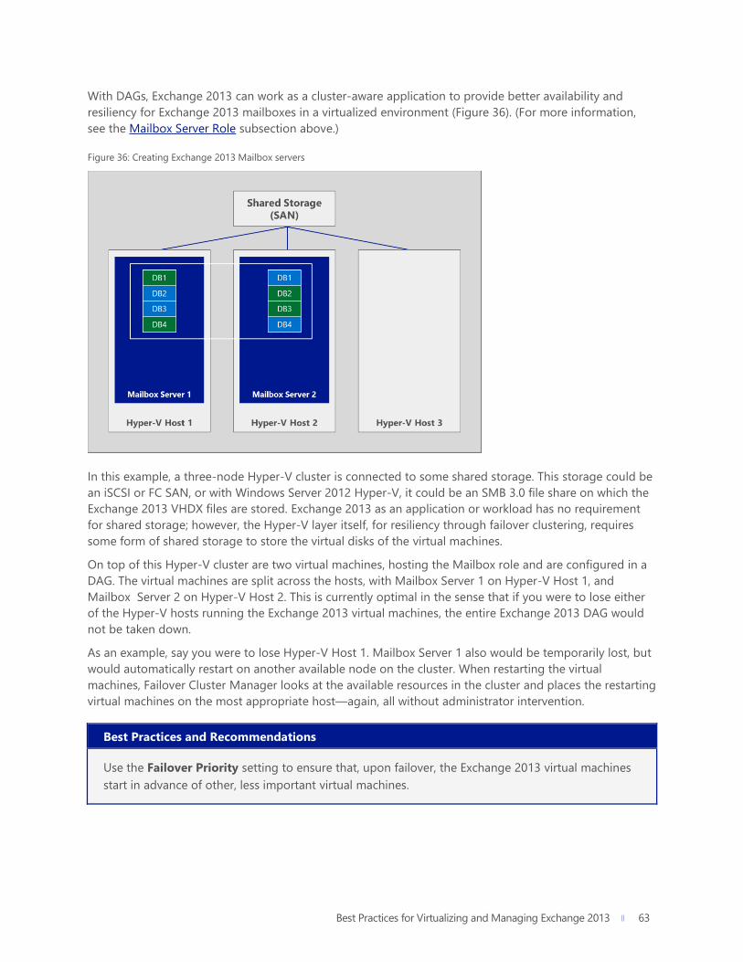
Best Practices for Virtualizing and Managing Exchange 2013 63
63
With DAGs, Exchange 2013 can work as a cluster-aware application to provide better availability and
resiliency for Exchange 2013 mailboxes in a virtualized environment (Figure 36). (For more information,
see the Mailbox Server Role subsection above.)
Figure 36: Creating Exchange 2013 Mailbox servers
In this example, a three-node Hyper-V cluster is connected to some shared storage. This storage could be
an iSCSI or FC SAN, or with Windows Server 2012 Hyper-V, it could be an SMB 3.0 file share on which the
Exchange 2013 VHDX files are stored. Exchange 2013 as an application or workload has no requirement
for shared storage; however, the Hyper-V layer itself, for resiliency through failover clustering, requires
some form of shared storage to store the virtual disks of the virtual machines.
On top of this Hyper-V cluster are two virtual machines, hosting the Mailbox role and are configured in a
DAG. The virtual machines are split across the hosts, with Mailbox Server 1 on Hyper-V Host 1, and
Mailbox Server 2 on Hyper-V Host 2. This is currently optimal in the sense that if you were to lose either
of the Hyper-V hosts running the Exchange 2013 virtual machines, the entire Exchange 2013 DAG would
not be taken down.
As an example, say you were to lose Hyper-V Host 1. Mailbox Server 1 also would be temporarily lost, but
would automatically restart on another available node on the cluster. When restarting the virtual
machines, Failover Cluster Manager looks at the available resources in the cluster and places the restarting
virtual machines on the most appropriate host—again, all without administrator intervention.
Best Practices and Recommendations
Use the Failover Priority setting to ensure that, upon failover, the Exchange 2013 virtual machines
start in advance of other, less important virtual machines.

Best Practices for Virtualizing and Managing Exchange 2013 64
64
Continuing this example, even though Mailbox Server 1 was down for a short period of time, the level of
built-in high availability in Exchange 2013, at the DAG level, ensures that users are still able to access
information and connect to their mailboxes via Mailbox Server 2, which was still running during the
outage of Hyper-V Host 1 (Figure 37).
Figure 37: Reestablishing the DAG after failing over Mailbox Server 1 on another host
This dual layer of availability—specifically, combining Exchange-level availability with host-level
availability—means that within a few minutes, both VMs will be fully online and the administrator can
then rebalance the databases within the DAG, thereby restoring the highest levels of availability that were
experienced before the outage. Whilst we’ve focused on the DAG here, the information is equally
applicable to the CAS Array to distribute the CAS functionality across multiple VMs.
With the Exchange 2013 virtual machines now stored on a Hyper-V cluster, individual virtual machines can
be moved around the cluster using live migration.
Best Practices and Recommendations
When performing live migration of DAG members, follow these key points:52
If the server offline time exceeds five seconds, the DAG node will be evicted from the
cluster. Ensure that the hypervisor and host-based clustering use the Live Migration
technology in Hyper-V to help migrate resources with no perceived downtime.
If you are raising the heartbeat timeout threshold, perform testing to ensure that
migration succeeds within the configured timeout period.
On the Live Migration network, enable jumbo frames on the network interface for each
host. In addition, verify that the switch handling network traffic is configured to support
jumbo frames.

Best Practices for Virtualizing and Managing Exchange 2013 65
65
Deploy as much bandwidth as possible for the Live Migration network to ensure that the
live migration completes as quickly as possible.
In the prior example, placing Mailbox Server 1 on a separate host from Mailbox Server 2 was ideal
because it ensured that if a host were lost, the entire DAG would not be lost as well. To help enforce this
kind of configuration, you can use some of the features within the Hyper-V cluster, such as Preferred and
Possible Owners. Importantly, to ensure that certain virtual machines stay apart on different hosts, you
also can use the AntiAffinityClassNames property of the failover cluster.
Best Practices and Recommendations
In this example, the administrator can create two Anti-Affinity Groups:
$CASAntiAffinity = New-Object System.Collections.Specialized.StringCollection
$CASAntiAffinity.Add("CAS Array")
$DAGAntiAffinity = New-Object System.Collections.Specialized.StringCollection
$DAGAntiAffinity.Add("DAG")
With the affinity class names defined, the administrator can assign them to the cluster groups.
Once again, the Get-ClusterGroup cmdlet can be used to update the value of this property for each
virtual machine:
(Get-ClusterGroup -Name EXCH-CAS1).AntiAffinityClassNames = $CASAntiAffinity
(Get-ClusterGroup -Name EXCH-CAS2).AntiAffinityClassNames = $CASAntiAffinity
(Get-ClusterGroup -Name EXCH-DAG1).AntiAffinityClassNames = $DAGAntiAffinity
(Get-ClusterGroup -Name EXCH-DAG2).AntiAffinityClassNames = $DAGAntiAffinity
In addition, customers can take advantage of the Failover Priority setting to help control the start
order of virtual machines upon failover.
These settings and configuration options can help to ensure that as you scale out an Exchange 2013
infrastructure on Hyper-V hosts, you are ensuring the highest levels of both performance and resiliency by
combining Exchange and Hyper-V high availability solutions.
Best Practices for Virtualizing and Managing Exchange 2013 66
66
System Center 2012 SP1 System Center 2012 SP1 provides several components that give IT the ability to streamline infrastructure
management and—as discussed in this guide specifically—to better deploy, manage, maintain, and
protect Exchange 2013 in a virtualized environment.
Comprehensive Management Capabilities Cloud computing is transforming the way organizations provide and consume IT services with the promise
of more productive infrastructure and more predictable applications. System Center 2012 SP1 delivers on
this promise by enabling your enterprise to benefit from private, hosted, and public cloud computing
while still supporting your unique business needs. It helps to organize your IT assets—network, storage,
and compute—into a hybrid cloud model spanning private cloud and public cloud services from a single
console view.
Infrastructure management: System Center 2012 SP1 provides a common management toolset to help
you configure, provision, monitor, and operate your IT infrastructure. If your infrastructure is like that of
most organizations, you have physical and virtual resources running heterogeneous operating systems.
The integrated physical, virtual, private, and public cloud management capabilities in System Center 2012
SP1 can help you ensure efficient IT management and optimized ROI of those resources.
Service delivery and automation: System Center 2012 SP1 helps you simplify and standardize your data
center with flexible service delivery and automation. Using the Service Manager and Orchestrator
components of System Center 2012 SP1, you can automate core organizational process workflows like
incident management, problem management, change management, and release management. You can
also integrate and extend your existing toolsets and build flexible workflows (or runbooks) to automate
processes across your IT assets and organizations.
Application management: System Center 2012 SP1 offers unique application management capabilities
that can help you deliver agile, predictable application services. Using the App Controller, Operations
Manager, and Virtual Machine Manager components of System Center 2012 SP1, you can provide
Applications as a Service—where a “service” is a deployed instance of a cloud-style application along with
its associated configuration and virtual infrastructure.
Virtual Machine Manager System Center 2012 SP1 Virtual Machine Manager (VMM) is the control center of a virtualized Exchange
2013 deployment. This subsection takes a deeper dive into VMM by discussing the following topics:
centralized fabric configuration, virtual machine creation, virtual machine deployment, Dynamic
Optimization, virtual machine priority and affinity, availability sets, and private clouds.

Best Practices for Virtualizing and Managing Exchange 2013 67
67
Centralized Fabric Configuration
System Center 2012 SP1 Virtual Machine Manager (VMM) enables the IT administrator to quickly and
easily configure and manage virtualization hosts, networking, and storage resources in order to create and
deploy virtual machines to host key Exchange 2013 components (Figure 38).
Figure 38: System Center 2012 SP1 Virtual Machine Manager - Overview
In addition to managing Hyper-V, VMM also provides management for Citrix XenServer and VMware
ESX/i hosts and host clusters on which virtual machines and services can be deployed. To help organize
hosts and the deployment of virtual machines, the IT administrator can create host groups based on
considerations such as physical site location or resource allocation.
In terms of networking, VMM manages resources such as logical networks, IP address pools, and load
balancers that are used to deploy virtual machines and services. VMM also manages storage resources
like storage classifications, LUNs, and storage pools that are made available to Hyper-V hosts and host
clusters.
Virtual Machine Creation
The VMM management console provides a number of capabilities and features that can be used to
accelerate and optimize the deployment of virtual machines to be used for Exchange 2013.
Physical-to-Virtual Conversions
VMM offers an inbox physical-to-virtual (P2V) capability to quickly and efficiently convert physical
Exchange Servers to virtual Exchange Servers that run on Hyper-V. VMM offers two methods for
conversion of physical machines: online and offline.
With an online conversion, the source computer continues to perform normal operations during the
conversion, and it is available throughout the process. VMM creates a copy of local NTFS volumes and

Best Practices for Virtualizing and Managing Exchange 2013 68
68
data from VSS-aware applications. VMM uses the Volume Shadow Copy Service (VSS) to ensure that data
is backed up consistently while the server continues to service user requests. VMM uses this read-only
snapshot to create a VHD.
For a busy Exchange Server, however, the point-in-time local copy for the online P2V will be out of date
very quickly. Therefore, an automated offline conversion may be more appropriate. Here, the source
computer restarts into the Windows Preinstallation Environment (Windows PE), and then VMM clones the
volume to a VHD. Offline P2V conversion is the only method to reliably migrate FAT volumes, and it is the
recommended method for converting domain controllers. In addition, offline P2V conversion can be the
most reliable way to ensure data consistency.
Virtual Machine Profiles and Templates
In VMM, a profile is a library resource containing specifications that can be applied to a new virtual
machine or virtual machine template. A template encapsulates a standard set of configuration settings
that can be used when creating a virtual machine. Templates can help you to quickly create virtual
machines with consistent hardware and operating system settings. This can be extremely useful for the
rapid deployment of Exchange Server virtual machines into an infrastructure. Templates also can be used
to restrict the virtual machine settings available to self-service users creating new virtual machines.
Profiles are used when creating templates. A template typically consists of a hardware profile, an
operating system profile, and a VHD that will be used by the virtual machine created with the template.
The VHD/X might be stored in the VMM library, or it might be a disk from an existing virtual machine.
The hardware and operating system profiles are discussed in more detail below:
Hardware profile: A hardware profile defines hardware configuration settings such as CPU,
memory, network adapters, video adapter, DVD drive, floppy drive, COM ports, and the priority
given the virtual machine when allocating resources on a virtual machine host (Figure 39).
Figure 39: System Center 2012 SP1 Virtual Machine Manager – Hardware Profile

Best Practices for Virtualizing and Managing Exchange 2013 69
69
Guest operating system profile: A guest operating system profile defines operating system-
configured settings that will be applied to a virtual machine created with the template. This profile
defines common operating system settings, including type of operating system, roles and features
to be enabled, computer name, administrator password, domain name, product key, time zone,
answer file, and run-once file (Figure 40).
Figure 40: System Center 2012 SP1 Virtual Machine Manager – Guest Operating System Profile
On their own, however, these profiles are not enough to be classified as a template. A template contains a
number of other key elements that help to accelerate the deployment of new virtual machines into the
infrastructure. It is important to note that templates are database objects stored in the library catalog of
the VMM database; they are not represented by physical configuration files. Templates can be created as
follows:
From an existing virtual hard disk or template stored in the library.
From an existing virtual machine deployed on a host.
Best Practices and Recommendations
One of the easiest ways to create a new template is to generate a new, blank virtual machine with
the desired hardware settings; install the chosen Windows operating system; install any relevant
updates or patches; and, once complete, shut the virtual machine down.
An administrator can then use the VMM Template Creation wizard to transform this “gold virtual
machine” into a new template. (If you want to keep the original, make a clone of the gold virtual
machine before the template creation process.) Once VMM has finished creating the template, it
will store the relevant files in the library. The administrator can then begin deploying new virtual
machines from this template.

Best Practices for Virtualizing and Managing Exchange 2013 70
70
Once the template is created, you can start to use some other profiles to enhance the template and
accelerate deployment of virtual machines that have specific applications within them. One such key
profile is the application profile. Application profiles provide instructions for installing Microsoft
Application Virtualization (Server App-V) applications, Microsoft Web Deploy applications, and Microsoft
SQL Server data-tier applications (DACs). For Exchange 2013, scripts could also be included as part of the
application profile; scripts can be used to automate an unattended installation of Exchange 2013 once the
virtual machine has been deployed. Additional information can be found on TechNet to help to guide
administrators through this process.
Service Templates
“Regular” templates, like the gold virtual machine template, can be deployed as they are, without further
modification. However, with the power of service templates, administrators (specifically Exchange
administrators) can deploy multiple virtual machines simultaneously to host Exchange.
In VMM, a service is a set of virtual machines that are configured and deployed together and are
managed as a single entity (for example, a deployment of a multi-tier line-of-business application). In the
VMM management console, you can use the Service Template Designer to create a service template,
which defines the configuration of the service. The service template includes information about what
virtual machines to deploy as part of the service, which applications to install on the virtual machines, and
what networking configuration to use for the service (including the use of a load balancer, if required).
The service template can make use of existing virtual machine templates, or you can define the service
from the ground up.
After the service template is created, you can deploy the service to a private cloud or to virtual machine
hosts. After the service is deployed, you can update the service template and then deploy those changes
to the existing service. Alternatively, you can deploy additional virtual machines to an existing service in
order to provide other resources for the service.
Virtual Machine Deployment
Thus far, this section has discussed how the template process can accelerate deployment of virtual
machines to host Exchange 2013, as well as how a template can contain scripts to install Exchange 2013 in
an unattended way. However, VMM also provides guidance on deployment: It can decide where to place
the virtual machine, and can move the virtual machine around the infrastructure if better performance for
that workload can be delivered elsewhere.
Intelligent Placement
VMM can help to identify the most appropriate physical host servers for virtualized Exchange Server
workloads. This Intelligent Placement technology not only can make administrative tasks easier, but also
can help to ensure that data center resources are deployed properly and align with business goals (Figure
41).

Best Practices for Virtualizing and Managing Exchange 2013 71
71
Figure 41: System Center 2012 SP1 Virtual Machine Manager – Intelligent Placement
Intelligent Placement in VMM inputs host system data, workload performance history, and administrator-
defined business requirements into sophisticated algorithms. This provides easy-to-understand, ranked
results that can take the guesswork out of the placement task and help to ensure that workloads are
spread across physical resources for optimal performance.
This placement also takes into account situations where a virtual machine requires specific hardware
offload capabilities, such as SR-IOV, as defined in the template. If these capabilities are not available on a
particular host, that host will not receive a star ranking as part of the Intelligent Placement destinations.
Storage Classification
VMM also provides the ability for an administrator to apply simple classifications to storage, which can be
used for storing and running Exchange Server virtual machines. Storage can be classified in any way that
the administrator wants, but common examples include terms such as “Bronze,” “Silver,” and “Gold,” which
may represent I/O characteristics, capacity, performance, and redundancy of the underlying storage array.
For example, consider the storage options and requirements for the Mailbox Server role in Exchange 2013:
Bronze might be low-capacity solid-state drives in an older SAN; Silver might be SAS drives in a newer
array; and Gold might be high-capacity SATA drives. These storage classifications can be used in an
Exchange 2013 virtual machine template so that VMM automatically ensures that a chosen type of
storage will be used for a particular deployment.53

Best Practices for Virtualizing and Managing Exchange 2013 72
72
Dynamic Optimization
Once Exchange 2013 virtual machines have been deployed onto the Hyper-V cluster, VMM actively
monitors key cluster and host metrics—such as CPU, Memory, Disk, and Network—to see if it can better
balance the virtual machine workloads across different hosts (Figure 42). For example, you may have a
number of hosts in a cluster, and one of the hosts has some Exchange 2013 virtual machines that are
exhibiting higher levels of demand than some others on other hosts. VMM can recognize this, and
automatically live migrate, with no downtime, some of the other virtual machines on that busy host to
less-busy hosts, freeing up valuable resources. This helps to ensure that workloads such as Exchange
2013, inside the virtual machines always receive the resources they need to meet demand, without
impacting other workloads running on the cluster.
Figure 42: System Center 2012 SP1 Virtual Machine Manager – Dynamic Optimization
Best Practices and Recommendations
Dynamic Optimization can be configured on a host group to migrate virtual machines within host
clusters with a specified frequency and aggressiveness. Aggressiveness determines the amount of
load imbalance that is required to initiate a migration during Dynamic Optimization. By default,
virtual machines are migrated every 10 minutes with medium aggressiveness. When configuring
frequency and aggressiveness for Dynamic Optimization, you should factor in the resource cost of
additional migrations against the advantages of balancing load among hosts in a host cluster. By
default, a host group inherits Dynamic Optimization settings from its parent host group.

Best Practices for Virtualizing and Managing Exchange 2013 73
73
Virtual Machine Priority and Affinity
If you deploy virtual machines on a host cluster, you can use VMM to configure priority settings for
them. With these settings, the cluster starts or places high-priority virtual machines before medium-priority
or low-priority virtual machines. This ensures that the high-priority virtual machines, like those running
Exchange Server, are allocated memory and other resources first, for better performance. Also, after a
node failure, if the high-priority virtual machines do not have the necessary memory and other resources
to start, the lower priority virtual machines will be taken offline to free up the necessary resources for the
high-priority machines. Virtual machines that are preempted are later restarted in priority order.
You can also configure priority settings in a virtual machine template so that any virtual machines created
with that template will have the specified virtual machine priority.
VMM also provides the ability for an administrator to influence the placement of virtual machines on the
nodes of the host cluster. As an administrator, you can do this by defining Preferred Owners and
Possible Owners for the virtual machines—ensuring that certain virtual machines can only run on certain
hosts, or certain virtual machines will never run on a particular host (Figure 43).
Figure 43: System Center 2012 SP1 Virtual Machine Manager – Preferred and Possible Ownership
Availability Sets
When you place multiple virtual machines in an availability set, VMM attempts to keep those virtual
machines on separate hosts whenever possible (Figure 44). This helps to improve continuity of service.
Another way to configure this setting is to use Windows PowerShell commands for failover clustering. In
this context, the setting appears in the Get-ClusterGroup listing and is called AntiAffinityClassNames. Note
that you can also configure availability sets in a service template to specify how virtual machines created
with that template should be placed on hosts.

Best Practices for Virtualizing and Managing Exchange 2013 74
74
Figure 44: System Center 2012 SP1 Virtual Machine Manager – Availability Set for Exchange Virtual Machines
Best Practices and Recommendations
When creating a DAG or CAS array virtualized on top of a Hyper-V host cluster, consider keeping
the individual Exchange 2013 roles on separate hosts. If one physical host is lost, it will only take
down a single node of the DAG or CAS array because the availability set within VMM will have
ensured that the DAG/CAS array nodes are running on separate hosts on the Hyper-V cluster.
Private Clouds
A cloud can be defined as the set of hardware, networks, storage, services, and interfaces that combine to
deliver aspects of computing as a service. Cloud services include the delivery of software, infrastructure,
and storage over the Internet (as either separate components or a complete platform) based on user
demand. A private cloud is a cloud infrastructure that is provisioned and managed on-premises or off-
premises by an organization or a third party. The private cloud is deployed using the organization’s own
hardware to capitalize on the advantages of the private cloud model. Through VMM, an organization can
quickly and easily manage the private cloud definition, access to the private cloud, and the underlying
physical resources (Figure 45). It also can provide granular, role-based access to end users, application
owners, or in the case of this white paper, Exchange administrators.
Figure 45: System Center 2012 SP1 Virtual Machine Manager – Create Cloud Wizard
In VMM, a private cloud provides the following benefits:
Resource pooling: Through the private cloud, administrators can collect and present an
aggregate set of resources, such as storage and networking resources. Resource usage is limited
by the capacity of the private cloud and by user role quotas.
Opacity: Self-service users have no knowledge of the underlying physical resources.

Best Practices for Virtualizing and Managing Exchange 2013 75
75
Self-service: Administrators can delegate management and use of the private cloud while
retaining the opaque usage model. Self-service users do not need to ask the private cloud
provider for administrative changes beyond increasing capacity and quotas.
Elasticity: Administrators can add resources to a private cloud to increase capacity.
Optimization: Use of underlying resources is continually optimized without affecting the overall
private cloud user experience.
Best Practices and Recommendations
From an Exchange 2013 perspective, an IT administrator can define a cloud to be used exclusively
with Exchange 2013 virtual machines. The IT organization would define the capacity of the cloud,
which can use elements such as storage classifications to ensure that all virtual machines placed in
the Exchange cloud use a certain tier of storage. In addition, specific virtual machine templates and
service templates can be assigned to the Exchange 2013 cloud, helping to ensure that the only
virtual machines deployed into this cloud are those that have been sized a certain way and will host
Exchange 2013 once deployed. The templates also can contain the appropriate unattend scripts to
install Exchange 2013 virtual machines.
During the creation process, you select the underlying fabric resources to be available in the private cloud,
configure library paths for users, and set the capacity for the private cloud. Therefore, before you create a
private cloud, you should configure the fabric resources, such as storage, networking, library servers and
shares, host groups, and hosts.
Once the Exchange private cloud is created, an IT administrator can delegate access to certain users and
groups within the IT infrastructure, such as the Exchange administrators (Figure 46). The IT administrator
can determine—through rich, granular role-based controls—who can see what inside the cloud, and who
can perform which tasks associated with it.
Figure 46: System Center 2012 SP1 Virtual Machine Manager – User Roles

Best Practices for Virtualizing and Managing Exchange 2013 76
76
Users who are part of the newly created group can then access the cloud and associated virtual machine
templates and service templates through the VMM console or, for a true self-service experience, through
System Center 2012 SP1 App Controller.
App Controller Among the advantages of a private cloud is the ability to quickly provision and deprovision compute,
networking, and storage resources through virtual machines. With System Center 2012 SP1 App
Controller, IT administrators in your organization can give certain users (such as Exchange administrators)
the ability to access and consume private and public cloud infrastructure by self-provisioning
standardized virtual machines in a controlled environment. This helps to reduce administrative overhead
and improve time to market.
When an Exchange administrator logs on to the App Controller interface, an overview screen is
dynamically generated based on identity and shows what the administrator can access (Figure 47). By
selecting the Clouds option, as shown, the Exchange administrator sees accessible clouds. Note that the
Exchange administrator has access to the Exchange cloud, of which a significant amount of capacity has
already been used.
Figure 47: Using App Controller to access an Exchange private cloud as the Exchange administrator
In Figure 48, when Virtual Machines is selected, a list appears of the current virtual machines that are
visible to this particular Exchange administrator. It is important to note here that the Exchange
administrator sees only the virtual machines that the IT administrator has specifically provided and
enabled for consumption. The Exchange administrator does not see the rest of the virtual machines on a
particular host or cluster, even though this person’s own virtual machines may be running on those hosts
or clusters. In addition, the Exchange administrator can perform only certain tasks on the virtual machine;
in this example, the Exchange administrator cannot pause or save virtual machines, but can start, stop,
shutdown, and deploy new virtual machines.

Best Practices for Virtualizing and Managing Exchange 2013 77
77
Figure 48: Virtual machine view in App Controller for an Exchange administrator
In Figure 49, the Exchange administrator chooses a particular cloud. From here, the Exchange
administrator can choose from a list of provided virtual machine templates and service templates to
determine the final pieces of configuration (such as Service Name, VM Name, and OS Name) for a
customized deployment. When the Exchange administrator clicks Deploy, the virtual machine
provisioning process starts, and VMM automatically orchestrates the deployment and placement of the
new virtual machine, which subsequently can be used to run Exchange 2013.
Figure 49: Deploying a virtual machine with App Controller

Best Practices for Virtualizing and Managing Exchange 2013 78
78
Once the virtual machine is deployed, the Exchange administrator can access it through App Controller
and perform the tasks and actions that the IT administrator has enabled (Figure 50). The Exchange
administrator also can connect to the virtual machine through remote desktop to perform Exchange-
specific actions.
Figure 50: Connecting to a virtual machine through App Controller
Service Manager and Orchestrator To review, the subsections above have discussed:
How IT administrators can define a private cloud within VMM, generate templates, and assign
users/groups.
How, from that point forward, Exchange administrators can access the rich web interface of App
Controller to deploy into that cloud virtual machines that can be used to install and run Exchange
Server.
Now consider the scenario where IT administrators want to use App Controller for Exchange
administrators to access their virtual machines, but also want to enact a mechanism through which the
Exchange administrators must request new virtual machines, as needed, instead of creating them at will.
To manage this scenario, your organization needs the Service Manager and Orchestrator components of
System Center, as well as the free Cloud Services Process Pack download. Together, these elements, along
with other System Center components like VMM, deliver a self-service infrastructure-as-a-service (IaaS)
platform that is managed by IT and consumed by end users, application owners, and Exchange
administrators.
Before examining how the components work together, it is important to understand what they provide
individually. Each component is discussed below in more detail.

Best Practices for Virtualizing and Managing Exchange 2013 79
79
Service Manager
IT service management: System Center 2012 SP1 Service Manager provides an integrated
platform for automating and adapting your organization’s IT service management best practices,
such as those found in Microsoft Operations Framework (MOF) and Information Technology
Infrastructure Library (ITIL). It provides built-in processes for incident and problem resolution,
change control, and asset lifecycle management.
ITaaS: Service Manager enables a rich self-service portal that provides role-based access to the
service catalog (Figure 51). The Self-Service Portal in System Center 2012 is a SharePoint website
that is accompanied by a set of Microsoft Silverlight applications. The SharePoint environment
provides a foundation on which the portal can be customized. It also provides a set of building
blocks for extending the features that users can access through a web browser.
Figure 51: Self-service portal in Service Manager
Integration: Connectors simplify and streamline integration between Service Manager and other
System Center components. You can use Service Manager connectors to import data as
configuration items from Active Directory Domain Services, Configuration Manager, Orchestrator,
VMM, and Operations Manager. In addition, you can import alerts from Operations Manager and
configure them to automatically generate incidents in Service Manager. You can also import data
from comma-separated value (CSV) files into the Service Manager database.
Business intelligence: Service Manager delivers a powerful data warehouse for rich, integrated
reporting. Service Manager reports enable you to collect and view data and trends from across
the business environment. For example, you can generate a report that shows the number of
incidents that occur in a specific time frame. You can then use that information to calculate the
cost of each incident (in hours) and to identify trends and take preventative measures to reduce
the cost and occurrence of incidences.

Best Practices for Virtualizing and Managing Exchange 2013 80
80
Orchestrator
Custom automation: System Center 2012 SP1 Orchestrator provides tools to build, test, debug,
deploy, and manage automation in your environment. These automated procedures, called
runbooks, can function independently or start other runbooks (Figure 52). The standard activities
defined in every installation of Orchestrator provide a variety of monitors, tasks, and runbook
controls, which you can integrate with a wide range of system processes. Each activity in a
runbook publishes data that is available to any subsequent activity in that runbook. You can use
this published data to provide dynamic decision-making capabilities (like creating emails, alerts,
log files, accounts, and more).
Figure 52: Sample runbook in Orchestrator
Your IT organization can use Orchestrator to improve efficiency and reduce operational costs to
support cross-departmental objectives. Orchestrator provides an environment with shared access
to common data. By using Orchestrator, you can evolve and automate key processes between
groups and consolidate repetitive manual tasks. You can automate cross-functional team
processes and enforce best practices for incident, change, and service management by creating
runbooks that are customized for your requirements. Through automation, regularly recurring
tasks reduce the number of manual and error-prone activities in your environment, helping to
improve reliability and predictability.
Cross-platform integration: Orchestrator integrates with System Center, other Microsoft
products, and non-Microsoft products to enable interoperability across the data center.
Orchestrator improves efficiency across multiple tools, systems, and departments by eliminating
or crossing technology and organizational process structures. You can extend the capabilities of
Orchestrator with integration packs that include additional functionality for both Microsoft and
non-Microsoft products and technologies. Orchestrator activities and integration packs reduce

Best Practices for Virtualizing and Managing Exchange 2013 81
81
unanticipated errors and shorten service delivery time by automating the common tasks
associated with enterprise tools and products.
End-to-end orchestration: Orchestration is the collective name for the automated arrangement,
coordination, and management of systems, software, and practices. It enables the management of
complex cross-domain processes. Orchestrator provides the tools for orchestration to combine
software, hardware, and manual processes into a seamless system. These tools let you connect
and automate workflows.
Just as manufacturing companies have automated common and repeatable tasks from their
production processes, you can adopt this same efficiency in the IT environment by using
Orchestrator to seamlessly perform and monitor your IT processes. Orchestrator can handle
routine tasks, ensure process enforcement, and reliably meet the demands of the largest
enterprises. Orchestrator interoperates with other System Center products to integrate IT
administrative tasks from start to finish.
Extensible structure: If you have a custom in-house solution, Orchestrator provides extensible
integration to any system through the Orchestrator Integration Toolkit. You can create custom
integrations that allow Orchestrator to connect to any environment. Orchestrator uses a
Representational State Transfer (REST)-based web service that can perform processes like start
and stop runbook jobs and get reporting information in Open Data protocol (OData) format. The
web service lets you develop applications that can use live data from Orchestrator.
Cloud Services Process Pack
Infrastructure as a service: IaaS is a service-centric model for requesting and provisioning data
center resources. The System Center Cloud Services Process Pack is the Microsoft IaaS solution
built on the System Center platform. With the Cloud Services Process Pack, your organization can
realize the benefits of IaaS while simultaneously using your existing investments in
Service Manager, Orchestrator, VMM, and Operations Manager.
Corporate data centers are in transition. The recent shift from physical to virtual environments is
now being replaced by an interest in moving to the cloud—specifically both private and public
cloud infrastructures. Private cloud management assets are being delivered with Service Manager,
and a key part of this solution is the self-service experience. This experience is now significantly
enhanced by the Cloud Services Process Pack.
Moreover, IT organizations considering IaaS need to examine and adapt their existing tools,
processes, workflows, and automation to meet the requirements of an effective cloud services
implementation. While it is critical that the underlying features (such as the Self-Service Portal,
ticketing infrastructure, notifications, workflows, and automation) integrate well with each other
and account for industry-wide best practices, the work involved to ensure an effective cloud
services implementation can be daunting and time-consuming. The Cloud Services Process Pack
addresses these concerns by enabling IaaS while incorporating domain expertise and best
practices from organizations that have successfully deployed IaaS.
Implications for Exchange Server
The Service Manager, Orchestrator, and Cloud Services Process Pack components work together to form a
powerful IaaS solution. With this solution, designated users like Exchange administrators can request

Best Practices for Virtualizing and Managing Exchange 2013 82
82
infrastructure; once the request is approved, integrated automation orchestrates delivery of and access to
the infrastructure—reducing the need for IT involvement and accelerating time to market.
Using the key components of System Center and the Cloud Services Process Pack, IT administrators can
define a rich self-service experience for Exchange administrators who want to request infrastructure to run
their Exchange workloads. In Figure 53, when the Exchange administrator logs on to the Contoso Portal,
the portal recognizes who the user is. Role-based access is key to the Service Manager self-service
experience, and the portal dynamically generates content based on the specific user.
Figure 53: Self-service portal in Service Manager
Figure 54 shows the Service Offerings page of the portal. Service Offerings essentially group together
requests that the specific user can make. In this example, the Exchange administrator selects the Service
Offering entitled Private Cloud Infrastructure Services to be presented with available requests.
Figure 54: Service Offerings page and related requests in Service Manager
The available requests are essentially the menu of choices that IT has provided for the DBA. The Cloud
Services Process Pack provides all of these in the box, and they can be used as templates for further
customization by IT. Example requests include:
Tenant Registration
Tenant Update Registration

Best Practices for Virtualizing and Managing Exchange 2013 83
83
Cloud Resources Subscription
Cloud Resources Update Subscription
Virtual Machine
Virtual Machine Update
Tenant Registration Cancellation
Cloud Resources Subscription Cancellation
From an Exchange perspective, IT can define specific requests that relate to Exchange Server. These
requests can be general or specific—for example, a request for IT to create a pool of resources for
Exchange administrators, or a request for a specific virtual machine to host a new installation of Exchange
Server. Remember the previous example where the Exchange administrator used App Controller to deploy
a virtual machine from a service template. In the current example, the same process is taking place, but
the Exchange administrator is making a request to have the activity performed (Figure 55). If the request is
approved, Orchestrator works in conjunction with Service Manager and VMM to create and deliver the
virtual machine. From there, the Exchange administrator can interact with the virtual machine through
App Controller.
Figure 55: Making a cloud resource request in Service Manager
Note that the Exchange administrator can request a private cloud and specify its capacity, recovery service
level, and antivirus and monitoring status. Once the request is submitted, the appropriate IT administrator
is notified to initiate approval. Upon approval, Orchestrator, as part of the integrated CSPP runbooks,
plugs in the relevant information from the form; orchestrates the creation of the cloud with VMM; and
sets up the relevant monitoring and protection with Operations Manager and Data Protection Manager.
The Exchange administrator receives notification upon completion and then is able to access the
resources with App Controller or through remote desktop directly into the virtual machine.

Best Practices for Virtualizing and Managing Exchange 2013 84
84
Operations Manager Microsoft has a long history of defining and refining monitoring capabilities for its products. System
Center 2012 SP1 Operations Manager continues this tradition as a solution with a deeper level of insight
and improved scalability. With Operations Manager, your organization can gain levels of visibility into its
infrastructure at every level of the stack, helping to ensure that the infrastructure is optimized and running
efficiently. Fundamentally, Operations Manager provides infrastructure monitoring that is flexible and cost
effective, better ensures the predictable performance and availability of vital applications, and offers
comprehensive oversight of your data center and cloud—both private and public.
Operations Manager enables IT administrators to monitor services, devices, and operations for many
computers in a single console (Figure 56). Operations Manager includes numerous views that show state,
health, and performance information, as well as alerts generated for availability, performance,
configuration, and security situations. With these tools, you can gain rapid insight into the state of the IT
environment and the IT services running across different systems and workloads.
Figure 56: Dashboard in Operations Manager
Exchange 2013 Management Pack
The ability to provide end-to-end management across infrastructure is a critical step in ensuring the
health of the hosts and clusters, virtual machines, and private cloud itself. Further, Operations Manager
can be used to monitor mission-critical Exchange Server workloads using the Exchange 2013
Management Pack.

Best Practices for Virtualizing and Managing Exchange 2013 85
85
The Microsoft Exchange 2013 Management Pack provides comprehensive service health information for
an Exchange infrastructure and has been engineered for organizations that include servers running
Exchange 2013. The key feature of this management pack is user-focused monitoring. The simplified
dashboard focuses on the user experience and makes it easier for an administrator to quickly determine
exactly what users are experiencing.
The management pack provides a number of useful views to help an Exchange 2013 administrator
understand the health of the Exchange 2013 infrastructure. The Active Alerts view shows you all the alerts
that are raised and currently active in your Exchange organization. You can click on any alert and see more
information about it in the details pane. This view essentially provides you with a yes/no answer to the
basic question, “Is there anything wrong in my Exchange deployment?” Each alert corresponds to one or
more issues for a particular health set. Also, depending on the particular issue, there may be more than
one alert raised.
If you see an alert in the Active Alerts view, your first step is to check the Organization Health view
(Figure 57). This is the primary source of information for the overall health of your organization. It shows
you specifically what is impacted in your organization, like Active Directory Sites and Database Availability
Groups.
Figure 57: Exchange 2013 Organization Health view in Operations Manager

Best Practices for Virtualizing and Managing Exchange 2013 86
86
The Server Health view provides details about individual servers in your organization. Here, in Figure 58,
you can see the individual health of all your servers. Using this view, you can narrow down any issues to a
particular server.
Figure 58: Exchange 2013 Server Health view in Operations Manager
While going through the three views in the Exchange 2013 dashboard, you will notice that in addition to
the State column, you have four additional health indicators (Figure 59). Each of these health indicators
provides an overview of specific aspects of your Exchange deployment.
Customer Touch Points: Shows you what your users are experiencing. If the indicator is healthy,
it means that the problem is probably not impacting your users. For example, assume that a DAG
member is having problems, but the database failed over successfully. In this case, you will see
unhealthy indicators for that particular DAG, but the Customer Touch Points indicator will show as
healthy because users are not experiencing any service interruption.
Service Components: Shows you the state of the particular service associated with the
component. For example, the Service Components indicator for Microsoft Outlook Web Access
(OWA) indicates whether the overall OWA service is healthy.
Server Resources: Shows you the state of physical resources that impact the functionality of a
server.
Key Dependencies: Shows you the state of the external resources that Exchange depends on, like
network connectivity, DNS, and Active Directory.
Figure 59: Health indicators in Operations Manager

Best Practices for Virtualizing and Managing Exchange 2013 87
87
The Exchange 2013 Management Pack provides simple but powerful views that makes it easy and fast to
determine if your organization is healthy. However, the views are also robust and structured in a way to
quickly guide you to the root of the problem, should an alert be triggered.
Best Practices and Recommendations
If the Exchange administrator does not want to install the full Operations Manager console on a
local machine or if IT is not comfortable providing that level of access, the Operations Manager
web console is a good option (Figure 60). The web console can be accessed through a browser and
offers near-parity with the full console. This allows the Exchange administrator to access key
information, alerts, dashboards, and views focused on specific areas (such as Exchange 2013).
Figure 60: Web console for Operations Manager
Data Protection Manager Data Protection Manager (DPM) has been part of the System Center family since the 2006 version was
launched, and since then, it has continued to evolve with more enhanced capabilities around backup and
workload protection. With the 2012 SP1 release, there have been further incremental improvements in
DPM that make it an excellent companion for Hyper-V, offering granular, efficient protection of virtual
machines and key Microsoft workloads like Exchange, SQL, and SharePoint (Figure 61).

Best Practices for Virtualizing and Managing Exchange 2013 88
88
Figure 61: Key capabilities of Data Protection Manager
DPM provides continuous data protection for Exchange Server. DPM performs replication,
synchronization, and recovery point creation to provide reliable protection and rapid recovery of
Exchange data by both system administrators and end users. DPM also allows users to exclude virtual
machine page files from incremental backups to improve storage usage and backup performance.
Organizations can back up and restore critical data using Exchange-aware applications that also support
VSS Writer for Exchange 2013. The VSS component of Windows Server coordinates the activities of
providers, writers, and requesters for applications that create and use shadow copies. These applications
consist of a background service that performs the backup, a scheduling service that times the backup, and
a Windows GUI application console that controls and configures the backup and restore system. 54, 55
DPM protects databases for Exchange 2013 that are contained in a DAG. DPM also can be used to recover
Exchange 2013 mailboxes and mailbox databases.56 DPM supports the following types of recovery for
Exchange 2013 mailboxes:
Recover to an Exchange Server database: Recover only to Exchange Server recovery databases.
Recover to a network location: Copy the database to a network folder.
Copy to tape: Create an on-tape copy of the database.
Likewise, DPM supports the following five types of recovery for Exchange 2013 mailbox databases:
Recover the database to its original location: Overwrite the existing copy of the database.
Recover the database to an alternate database: Restore to another database on an Exchange
Server.
Recover to an Exchange Recovery database: Recover to an Exchange Recovery database
instead of a standard mailbox database.
Recover to network location: Copy the database to a network folder.
Copy to tape: Create an on-tape copy of the database.

Best Practices for Virtualizing and Managing Exchange 2013 89
89
With System Center 2012 SP1, DPM now can back up data from the DPM server to offsite storage that is
managed by the Windows Azure Backup service. (Your organization must sign up for the service, and you
must download and install the Windows Azure Backup agent on the DPM server, which is used to transfer
the data between the server and the service.) With the new online backup capabilities in DPM, you can
expect the following benefits:
Reduced TCO: The Windows Azure Backup service can help to reduce TCO by providing
scalability, elasticity, and simplified storage management.
Peace of mind: The Windows Azure Backup service provides a reliable, secure, and robust offsite
solution for backup and recovery that is highly available. It also provides uninterrupted protection
for migrated virtual machines.
Simplicity: Windows Azure Backup workflows are seamlessly integrated into the existing DPM
backup, recovery, and monitoring workflows. The service also facilitates recovery of data from
individual mailboxes.

Best Practices for Virtualizing and Managing Exchange 2013 90
90
Conclusion Windows Server 2012 Hyper-V is a great fit for virtualizing Exchange 2013 workloads. As demand for
virtualization technology grows, Microsoft has continued to make it easier for organizations to choose to
virtualize workloads that were not previously considered good candidates. Virtualization of Exchange 2013
is a valid option for organizations looking to address the impact of any wasted resources from Exchange
deployments on underutilized hardware. In addition, Exchange virtualization delivers other significant
benefits, including increased dual-levels of resiliency, along with significant overall power and space
savings, improved server utilization, rapid server provisioning, and increased performance and
manageability. With Hyper-V technology, Microsoft provides a platform with flexible and robust
virtualization capabilities. Whether in your data center, with a service provider, or in a private cloud,
Microsoft provides flexibility and control to consume IT as a service—in whatever way best meets your
unique business needs.
Proper planning is required before virtualizing business-critical workloads like Exchange 2013, and it is
beneficial to understand the best practices and recommendations discussed in this guide. At a high level,
the fabric considerations can help you to effectively plan the physical infrastructure, including processors,
memory, storage, and network. Likewise, the agility and resiliency considerations can help you to
configure virtual machines using Exchange 2013 and Windows Server 2012 Hyper-V settings, depending
on various requirements.
Both Exchange 2013 roles (Client Access Server and Mailbox Server) are supported for virtualization.
Combining Exchange Mailbox servers that are part of a DAG with host-based failover clustering and
migration technology is also now supported. As a best practice, spend adequate time designing the
virtualized environment to avoid consequences later. For organizations that have high availability or site
resiliency needs, it is important to determine these requirements as a first step. For high availability, you
must deploy the same Exchange roles (for example, Client Access Server) across multiple physical Hyper-V
hosts to allow for load balancing and high availability. Therefore, never deploy either of the following on
the same Hyper-V host: Mailbox servers that are members of the same DAGs or all Client Access servers.
To optimize high availability and resiliency, Windows Server 2012 Hyper-V even lets you prioritize virtual
machines in a failover situation.
The Virtual Machine Configuration section provides a guide to design detailed architecture and system
specifications for building virtual machines for Exchange workloads. Remember that it is also necessary to
plan for needed resources for the virtual machines, including CPU, memory, storage, and network.
Windows Server 2012 Hyper-V offers increased virtual machine resource densities of up to 64 virtual
processors and 1 TB of RAM per virtual machine; this is a significant boost to virtualizing mission-critical,
heavy-duty workloads like Exchange Mailbox Server roles and multi-role servers.
Virtualizing Exchange 2013 with Windows Server 2012 gives organizations flexible deployment options,
both on-premises and in the cloud. System Center 2012 SP1 enables these organizations to deploy,
manage, maintain, and protect Exchange 2013 in a virtualized environment. System Center 2012 SP1
Virtual Machine Manager and Operations Manager provide a highly capable set of tools to manage and
deploy virtual machines to host the key Exchange 2013 components. Likewise, System Center 2012 SP1
Data Protection Manager provides continuous data protection and rapid data recovery for Exchange
Server using replication, synchronization, and recovery point creation.

Best Practices for Virtualizing and Managing Exchange 2013 91
91
Additional Resources For more information, please visit the following links:
Exchange 2013 for IT Pros
http://technet.microsoft.com/en-us/exchange/fp179701.aspx
Exchange 2013 Virtualization
http://technet.microsoft.com/en-us/library/jj619301(v=exchg.150).aspx
Windows Server 2012
http://www.microsoft.com/en-us/server-cloud/windows-server/default.aspx
Windows Server 2012 TechNet
http://technet.microsoft.com/en-us/windowsserver/hh534429.aspx
Microsoft System Center 2012
http://www.microsoft.com/en-us/server-cloud/system-center/default.aspx
Microsoft System Center 2012 TechNet
http://technet.microsoft.com/en-us/systemcenter/bb980621.aspx
What’s New in System Center 2012 SP1
http://technet.microsoft.com/en-us/systemcenter/bb980621.aspx

Best Practices for Virtualizing and Managing Exchange 2013 92
92
References 1 Microsoft. “Lab Validation Report: Microsoft Windows Server 2012 with Hyper-V and Exchange 2013.”
http://download.microsoft.com/download/C/2/A/C2A36672-19B9-4E96-A1E0-
8B99DED2DC77/ESG_Windows_Server_2012_with_Hyper-V_and%20Exchange_2013_Lab_Validation_Report.pdf
2 Gartner. “Magic Quadrant for x86 Server Virtualization Infrastructure.” Jun 2012.
http://www.gartner.com/technology/reprints.do?id=1-1AVRXJO&ct=120612&st=sb
3 Microsoft. “System Center 2012 - Infrastructure Management.”
http://www.microsoft.com/en-us/server-cloud/system-center/infrastructure-management.aspx
4 Microsoft TechNet Blog. “The Perfect Combination: SQL Server 2012, Windows Server 2012 and System Center 2012.” Dec 2012.
http://blogs.technet.com/b/dataplatforminsider/archive/2012/12/06/the-perfect-combination-sql-server-2012-windows-server-
2012-and-system-center-2012.aspx
5 Microsoft TechNet. “Installing Windows Server 2012.” May 2012.
http://technet.microsoft.com/en-us/library/jj134246.aspx
6 Microsoft TechNet. “Windows Server Installation Options.”
http://technet.microsoft.com/en-us/library/hh831786.aspx
7 Microsoft MSDN. “Minimal Server Interface for Windows Server 2012.”
http://msdn.microsoft.com/en-us/library/windows/desktop/hh846317(v=vs.85).aspx
8 Microsoft. “Server Virtualization: Windows Server 2012.”
http://download.microsoft.com/download/5/D/B/5DB1C7BF-6286-4431-A244-
438D4605DB1D/WS%202012%20White%20Paper_Hyper-V.pdf
9 Coombes, David. “Module 1 - VM Scale Student Manual.” Sep 2012
http://download.microsoft.com/download/F/F/1/FF10F038-26CD-4B00-858C-C99C0D9FAB93/Module%201%20-
%20VM%20Scale%20Student%20Manual.pdf
10 Microsoft. “Server Virtualization: Windows Server 2012.”
http://download.microsoft.com/download/5/D/B/5DB1C7BF-6286-4431-A244-
438D4605DB1D/WS%202012%20White%20Paper_Hyper-V.pdf
11 Microsoft TechNet Blog. “Hyper-V VM Density, VP:LP Ratio, Cores and Threads.” Apr 2011.
http://blogs.technet.com/b/virtualization/archive/2011/04/25/Hyper-V-vm-density-vp-lp-ratio-cores-and-threads.aspx
12 Armstrong, Ben (MSDN Blog). “Hyper-V CPU Scheduling–Part 1.” Feb 2011.
http://blogs.msdn.com/b/virtual_pc_guy/archive/2011/02/14/hyper-v-cpu-scheduling-part-1.aspx
13 Microsoft MSDN. “Understanding Non-Uniform Memory Access.”
http://msdn.microsoft.com/en-us/library/ms178144.aspx
14 Microsoft. “Server Virtualization: Windows Server 2012.”
http://download.microsoft.com/download/5/D/B/5DB1C7BF-6286-4431-A244-
438D4605DB1D/WS%202012%20White%20Paper_Hyper-V.pdf
15 Microsoft. “Server Virtualization: Windows Server 2012.”
http://download.microsoft.com/download/5/D/B/5DB1C7BF-6286-4431-A244-
438D4605DB1D/WS%202012%20White%20Paper_Hyper-V.pdf
16 Microsoft MSDN. “Performance Tuning Guidelines for Windows Server 2012.” Oct 2012.
http://download.microsoft.com/download/0/0/B/00BE76AF-D340-4759-8ECD-C80BC53B6231/performance-tuning-guidelines-
windows-server-2012.docx
17 ten Seldam, Matthijs (TechNet Blog). “Windows Server - Sockets, Logical Processors, Symmetric Multi-Threading.” Oct 2012.
http://blogs.technet.com/b/matthts/archive/2012/10/14/windows-server-sockets-logical-processors-symmetric-multi-threading.aspx
18 Microsoft TechNet. “Exchange 2013 Virtualization.”
http://technet.microsoft.com/en-us/library/jj619301(v=exchg.150).aspx
19 Microsoft TechNet. “Storage Spaces - Designing for Performance.”
http://social.technet.microsoft.com/wiki/contents/articles/15200.storage-spaces-designing-for-performance.aspx
20 Microsoft TechNet. “Storage Spaces - Designing for Performance.”
http://social.technet.microsoft.com/wiki/contents/articles/15200.storage-spaces-designing-for-performance.aspx

Best Practices for Virtualizing and Managing Exchange 2013 93
93
21 Microsoft TechNet. “Storage Spaces - Designing for Performance.”
http://social.technet.microsoft.com/wiki/contents/articles/15200.storage-spaces-designing-for-performance.aspx
22 Barreto, Jose (TechNet Blog). “Hyper-V over SMB - Sample Configurations.“
http://blogs.technet.com/b/josebda/archive/2013/01/26/hyper-v-over-smb-sample-configurations.aspx
23 Microsoft. “Lab Validation Report: Microsoft Windows Server 2012: Storage and Networking Analysis.” Dec 2012.
http://download.microsoft.com/download/8/0/F/80FCCBEF-BC4D-4B84-950B-07FBE31022B4/ESG-Lab-Validation-Windows-Server-
Storage.pdf 24 Microsoft. “Lab Validation Report: Microsoft Windows Server 2012: Storage and Networking Analysis.” Dec 2012.
http://download.microsoft.com/download/8/0/F/80FCCBEF-BC4D-4B84-950B-07FBE31022B4/ESG-Lab-Validation-Windows-Server-
Storage.pdf 25 Microsoft TechNet. “Failover Clustering Hardware Requirements and Storage Options.” Aug 2012.
http://technet.microsoft.com/en-in/library/jj612869.aspx
26 Microsoft. “Networking: Windows Server 2012.”
http://download.microsoft.com/download/7/E/6/7E63DE77-EBA9-4F2E-81D3-9FC328CD93C4/
WS%202012%20White%20Paper_Networking.pdf
27 Microsoft. “Windows Server 2012 Product Overview.”
http://download.microsoft.com/download/B/3/0/B301FE04-ABAB-4C89-8631-0FCBE4147B84/WS_2012_Product_White_Paper.pdf
28 Microsoft TechNet. “Cluster-Aware Updating Overview.”
http://technet.microsoft.com/en-us/library/hh831694.aspx
29 Microsoft TechNet. “Configuring Availability Options for Virtual Machines in System Center 2012 SP1 – Overview.” Jan 2013.
http://technet.microsoft.com/en-us/library/jj628163.aspx
30 Microsoft TechNet. “What's New in Failover Clustering.” Sep 2012.
http://technet.microsoft.com/en-us/library/hh831414.aspx#BKMK_PLACE
31 Microsoft. “Server Virtualization: Windows Server 2012.”
http://download.microsoft.com/download/5/D/B/5DB1C7BF-6286-4431-A244-438D4605DB1D/
WS%202012%20White%20Paper_Hyper-V.pdf
32 Microsoft MSDN. “Performance Tuning Guidelines for Windows Server 2012.” Oct 2012.
http://download.microsoft.com/download/0/0/B/00BE76AF-D340-4759-8ECD-C80BC53B6231/performance-tuning-guidelines-
windows-server-2012.docx
33 Allen, Lindsey, et al. “Running SQL Server 2008 in a Hyper-V Environment.” Oct 2008.
http://download.microsoft.com/download/d/9/4/d948f981-926e-40fa-a026-5bfcf076d9b9/sql2008inhyperv2008.docx
34 Microsoft TechNet. “Configure the Memory for the Virtual Machines.” Jan 2013.
http://technet.microsoft.com/en-us/library/ff621103.aspx#ConfigMem
35 Microsoft TechNet Blog. “NUMA Node Balancing.” Dec 2009.
http://blogs.technet.com/b/winserverperformance/archive/2009/12/10/numa-node-balancing.aspx
36 Posey, Brien (TechNet Blog). “Virtualization: Optimizing Hyper-V Memory Usage.”
http://technet.microsoft.com/en-us/magazine/hh750394.aspx
37 Microsoft. “Implementing and Configuring Dynamic Memory.” June 2010.
http://download.microsoft.com/download/E/0/5/E05DF049-8220-4AEE-818B-
786ADD9B434E/Implementing_and_Configuring_Dynamic_Memory.docx
38 Microsoft TechNet. “Hyper-V Dynamic Memory Overview.” Feb 2012.
http://technet.microsoft.com/en-us/library/hh831766.aspx
39 Coombes, David. “Module 1 - VM Scale Student Manual.” Sep 2012.
http://download.microsoft.com/download/F/F/1/FF10F038-26CD-4B00-858C-C99C0D9FAB93/Module%201%20-
%20VM%20Scale%20Student%20Manual.pdf
40 Microsoft. “Server Virtualization – Windows Server 2012.”
http://download.microsoft.com/download/5/D/B/5DB1C7BF-6286-4431-A244-
438D4605DB1D/WS%202012%20White%20Paper_Hyper-V.pdf
41 Microsoft. “Server Virtualization – Windows Server 2012.”
http://download.microsoft.com/download/5/D/B/5DB1C7BF-6286-4431-A244-
438D4605DB1D/WS%202012%20White%20Paper_Hyper-V.pdf
42 Microsoft TechNet. “Configure the Memory for the Virtual Machines.” Jan 2013.
http://technet.microsoft.com/en-us/library/ff621103.aspx#ConfigMem

Best Practices for Virtualizing and Managing Exchange 2013 94
94
43 Microsoft. “Running SQL Server with Hyper-V Dynamic Memory.” Jul 2011.
http://download.microsoft.com/download/D/2/0/D20E1C5F-72EA-4505-9F26-
FEF9550EFD44/Best%20Practices%20for%20Running%20SQL%20Server%20with%20HVDM.docx
44 Rabeler, Carl. “Running Microsoft SQL Server 2008 Analysis Services on Windows Server 2008 vs. Windows Server 2003 and
Memory Preallocation: Lessons Learned.” Jul 2008.
http://sqlcat.com/sqlcat/b/technicalnotes/archive/2008/07/16/running-microsoft-sql-server-2008-analysis-services-on-windows-
server-2008-vs-windows-server-2003-and-memory-preallocation-lessons-learned.aspx
45 Microsoft TechNet. “Everything You Wanted to Know about SR-IOV in Hyper-V (Part 5).” Mar 2012.
http://blogs.technet.com/b/jhoward/archive/2012/03/16/everything-you-wanted-to-know-about-sr-iov-in-Hyper-V-part-5.aspx
46 Howard, John (Microsoft TechNet Blog. “Everything you wanted to know about SR-IOV in Hyper-V Part 6.” Mar 2012.
http://blogs.technet.com/b/jhoward/archive/2012/03/19/everything-you-wanted-to-know-about-sr-iov-in-hyper-v-part-6.aspx 47 ten Seldam, Matthijs (Microsoft TechNet Blog). “Windows Server 2012 Hyper-V and SR-IOV.”
http://blogs.technet.com/b/matthts/archive/2012/10/13/windows-server-2012-hyper-v-and-sr-iov.aspx
48 Microsoft MSDN. “SR-IOV VF Failover and Live Migration Support.” May 2013.
http://msdn.microsoft.com/en-in/library/windows/hardware/hh440249(v=vs.85).aspx
49 Microsoft. “Server Virtualization – Windows Server 2012.”
http://download.microsoft.com/download/5/D/B/5DB1C7BF-6286-4431-A244-
438D4605DB1D/WS%202012%20White%20Paper_Hyper-V.pdf
50 Microsoft TechNet. “Quality of Service (QoS) Overview.” Mar 2013.
http://technet.microsoft.com/en-us/library/hh831679.aspx#bkmk_bandwidth
51 Microsoft TechNet. “Load Balancing.”
http://technet.microsoft.com/en-us/library/jj898588(v=exchg.150).aspx
52 Microsoft. “Best Practices for Virtualizing Exchange Server 2010 with Windows Server 2008 R2 Hyper-V.”
http://download.microsoft.com/download/D/F/E/DFE6362D-7A77-4782-9D73-73FE5977C4EE/
Best_Practices_for_Virtualizing_Exchange_Server_2010_with_Windows_Server.docx
53 Microsoft TechNet. “Exchange 2013 Storage Configuration Options.”
http://technet.microsoft.com/en-in/library/ee832792(v=exchg.150).aspx
54 Microsoft TechNet. “Backup, Restore, and Disaster Recovery.” Nov 2012.
http://technet.microsoft.com/en-us/library/dd876874.aspx
55 Microsoft MSDN. “VSS Backup and Restore Evaluation Criteria.”
http://msdn.microsoft.com/en-us/library/exchange/aa579280(v=exchg.150).aspx
56 Microsoft TechNet. “Managing Protected Servers Running Exchange.”
http://technet.microsoft.com/en-us/library/hh757902.aspx