best performance – best service – best value · • leakage rates per mss sp-61 ... high...
TRANSCRIPT


Best Performance – Best Service – Best ValueSince 1973, MOGAS Industries, Inc. has been supplying
severe service metal seated ball valves for the most severe
applications, primarily in the refining, chemical/petrochemical,
power and mining industries.
MOGAS introduced its advanced technology to the refining
and petrochemical industries with the development of the
C-Series line, utilized to ensure the operational integrity of
a process and handle the plant’s severest applications.
MOGAS has continued to provide progressive solutions for
the process industries with improved metallurgical coatings,
leak-free sealing and timely deliveries.
MOGAS Valves for ProcessThrough years of field experience, working with major process
companies and a sophisticated performance analysis
procedure, MOGAS has developed a product line dedicated
to solving the excessive maintenance problems that plague
the process industries.
MOGAS Provides Solutions for ProcessToday’s refining complexes demand products that are reliable
and consistently:
• Provide emergency isolation
• Perform under extreme conditions such as high
temperature with heavy solids and coking, packing-in,
and abrasive, corrosive or erosive media
• Reduce unexpected downtime and maintenance costs
• Increase personnel and environmental safety
This 8” 2500# MOGAS valve was inspected after 12 years of installation. Despite the viscous polymer in the line, this valve was able to operatewithout mishap and was returned to service.
The MOGAS proprietary mate-lapping process of the ball and seats ensures 100% contact over entire sealing surface.
The MOGAS Solution
- 2 -
Initially installed over 10 years ago, this valve remains in service today providing reliable performance despite high temperature and pressures.

MOGAS Quality Control
- 3 -
QualityFull employee acceptance of quality is paramount to a successful Quality Assurance Program. MOGAS has established a culture of quality throughout the company, from the first customer inquiry to the final product shipment.
The MOGAS Quality Assurance Program encompasses a complete quality management system to ensure conformancewith national reference standards including ANSI/ASME Code requirements. When used as Power Operated ReliefValves, MOGAS severe service ball valves may be stampedwith the ASME “V” Stamp, to ensure they have been designed, manufactured, inspected and tested to meet therequirements of ASME Code Sections I, II and IX.
Testing• Leakage Rates per MSS SP-61• Shell Tests performed at 1.5 x Max Cold
Working Pressure• Seat Closure Tests performed at 1.1 x Max Cold
Working Pressure• All valves meet API 607• API 598 (upon request)
Engineering ServicesAt MOGAS, there is over 30 years of valve knowledge, applications engineering, and industry innovation. When there are special requirements, MOGAS engineers find the right solution. MOGAS is involved exclusively in the engineering and manufacturing of metal seated ball valves for the most severe services. Essentially, MOGAS is an engineering company which manufactures valves specific to customer application needs. MOGAS engineering specialists are available to analyze tough applications, design valves which meet punishing criteria and solve isolation, drain and vent problems.
Customer ServiceFrom commercial flexibility to outstanding service, the MOGAS goal is complete customer satisfaction. MOGAS field service representatives are available 24 hours a day, 365 days a year. MOGAS technical advisors will assist withinstallation or training. On-site coverage extends anywhere,bringing technical support to the harshest environments and the most remote locations. MOGAS goes wherever a solution is needed.
WarrantyMOGAS Industries, Inc. is pleased to offer MOGAS ball valves with a product warranty that is superior to other ball valve manufacturers. More detailed information is available in the standard terms and conditions of sale which accompanies a valve order.
Most Technologically AdvancedMOGAS engineers are equipped with the latest and mostsophisticated tools, such as finite element analysis (FEA) software enabling engineers to analyze a valve down to themost minute detail and SolidWorks —a parametric-driven modeling software.
With SolidWorks, real-time information is provided. Drawingsand spreadsheets can be linked within SolidWorks, so if the Billof Material is changed in any way, the changes are reflected onthe drawings as well, which eliminates errors.
MOGAS can provide 3-D viewing of valves, which can be putinto the piping schematics of specific plants. This enablesclients to see whether or not the valve will fit within theirschematics. The valve is viewable from all angles, 360 degreesaround. Another benefit is that any changes needed to bemade on the valve can be done instantly through e-mail, whichmeans no waiting for faxed documents.
Over 30 years of focused design and material research, specific to severe valve applications, has increased manyclients’ plant run-time and safety.

Process Applications
- 4 -
Partial Applications List
FCCU Frac Bottoms Pump, Strainer & Heat Exchanger Isolation
Best Practice List for Chevron/Texaco
Regeneration Spent Catalyst Dump Valve
Best Practice List for Shell
Installation at Exxon-Baytown
3rd or 4th Stage Cyclone Separator
Installation at Total/Fina/Elf-Milford Haven
Delayed Cokers Overhead Vapor Isolation
Installation at Frontier-El Dorado
Coker Drum Isolation
Installation at Frontier-Cheyenne
Heat Exchanger Isolation
Installation at Shell-Martinez
Drain & Vent Valves
Installation at Premcor-Port Arthur
CCR Units Lockhopper Isolation
Vent Valves
Platforming Reactor Isolation
Catalyst Addition Valves to the Lockhopper
MOGAS is 1 of only 2 approved vendors by UOP
Atmospheric or
Vacuum Crude
Units
Furnace Isolation
Filter Isolation
Installation at Conoco/Phillips-Borger
High Pressure
Ebulating Bed
Hydrocrackers
High Pressure Letdown Control Valve Isolation
Catalyst Handling Valves
ESD Valves
Hot Oil & H2 Furnace Isolation Valves
Heavy Coking Applications
Preferred Vendor for Lummus & Axxens
VCM Units Furnace Isolation
Preferred Vendor for Dow Chemical
LDPE Product Take-Off Valves
Inlet Feed Valves
Pump Isolation Valves
Installation at Dupont-Victoria
HDPE Product Take-Off Valves
Inlet Feed Valves
Pump Isolation Valves
Installation at Chevron-Cedar Bayou
Polypropylene Product Take-Off Valves
Inlet Feed Valves
Pump Isolation Valves
Installation at Dow Chemical-Freeport
TPA, IPA, PTA Isolation b/t 1st & 2nd Crystalizers
Installation at BP/Amoco-Indonesia, Charleston
Pulp & Paper Digestor Blowdown Valves
Green Liquor Valves
Black Liquor Valves
Steam Drain & Vent Valves
PORVs
Installation at Georgia Pacific & Smurfit-Stone
Coke particles suspended in gas travel through this 16”300# VCM Furnace Isolation Valve at high speed, makingthis a very abrasive service.
Twelve (12) years of continuous operation have beenrecorded for this 12” 3rd stage Cyclone Separator Valve.
MOGAS valves are available for a standard 10-12 week delivery with an expedited delivery available upon request.
Many valves are IN STOCK – Availablefor IMMEDIATE DELIVERY

- 5 -
CA-1AS
1" - 24"
150# to 2500#
RF, BW, RTJ, Clamp
A105, F5, F9, 347SS,
Hastalloy, Ti, All
Materials Available
MOGAS Valve Selection Guide for Process Applications
CA-DRI CA-HO1 S-Series * ISOLATOR RSVP MODEL
Size
Class
End
Connections
Body Materials
Trims
Coatings
Directional
Sealing / Solids
Capability
Application
or Process
Factory Stock
Page Number
410SS, 316SS,
Inconel, Ti, All
Materials Available
HVOF Chrome
Carbide & Tungsten
Carbide, Spray &
Fuse Coatings,
Ceramic Coatings,
Diffused Coatings
Bi-Directional
Sealing / Solids
Resistant
CCR Units
Delayed Cokers
Fluid Cokers
FCC Units
Atmospheric or
Vacum Crude Units
High Pres. Ebulating
Bed Hydrocrackers
Fixed Bed
Hydrocrackers
Szorb Units
Desulfurizartion Units
Gas to Liquid Units
Gasification Units
High Pres. / Temp, O2,
H or Flue Gas
Coal Liquefaction
Units
Polypropylene
HDPE
LDPE
Acetic Acid
VCM Units
TPA
IPA
Page 6
1" - 24"
150# to 2500#
RF, BW, RTJ, Clamp
A105, F5, F9, 347SS,
Hastalloy, Ti, All
Materials Available
410SS, 316SS,
Inconel, Ti, All
Materials Available
HVOF Chrome
Carbide & Tungsten
Carbide, Spray &
Fuse Coatings,
Ceramic Coatings,
Diffused Coatings
Unidirectional
Sealing / Solids
Proof
CCR Units
Delayed Cokers
Fluid Cokers
FCC Units
Atmospheric or
Vacum Crude Units
High Pres. Ebulating
Bed Hydrocrackers
Fixed Bed
Hydrocrackers
Szorb Units
Desulfurizartion Units
Gas to Liquid Units
Gasification Units
High Pres. / Temp, O2,
H or Flue Gas
Coal Liquefaction
Units
Polypropylene
HDPE
LDPE
Acetic Acid
VCM Units
TPA
IPA
Contact MOGAS
1/2" - 3"
1500# - 4500#
SW, BW, RTJ, Clamp,
RF
A105, F5, F9, 347SS,
Hastalloy, Ti, All
Materials Available
410SS, 316SS,
Inconel, Ti, All
Materials Available
HVOF Chrome
Carbide & Tungsten
Carbide, Spray &
Fuse Coatings,
Ceramic Coatings,
Diffused Coatings
Uni- or Bi-
Directional / Solids
Resistant
High Pres. Catalyst
Handling Valves
High Pres. Ebulating
Bed Units
High Pres. / Temp, O2,
H or Flue Gas
Coal Liquefaction
Units
LDPE
Page 6
1/2" - 30+"
150# - 4500#
Any End
Connections
Unlimited
Unlimited
Unlimited
CUSTOM
Per Customer
Requirements
* Custom Built with
Heavy Engineering
Involvement
Page 6
2" - 8"
150# - 300#
RF
CF8M (316SS)
316SS or
410SS Ball & Seats
w / Stellite #3
HVOF Chrome
Carbide
Bi-Directional
Valve / Solids
Resistant
Catalyst Handling
Slurries
Hydrogen
SZORB Gas Handling
Pulp & Paper
10,000 cycles or less
CCR Units
Lethal Gas
EDC Slurries
Dowtherm Handling
Solids Handling
Fuel Gas
Page 8
1/2" - 2-1/2"
150# - 4500#
SW, BW, Clamp, RF
A105, F22, 316SS,
Other Materials
Available
410SS or
Inconel 718 Ball &
Seats
HVOF Chrome
Carbide or Spray &
Fused Chrome
Carbide
Uni-directional
Sealing / Solids
Tolerant
Drains & Vents
for any process
Page 9
* Site visits by
Engineering or Service
staff recommended
Iron Carbide Units
DRI Units
Lethal Gases or Liquids
Direct Smelt
Applications
Jet Engine Test
Equipment
Extreme
Temperatures
and / or Pressures
Extreme Cycling
Services
Extreme Temp Shock
Applications
Tungsten
HexaFluoride
Autoclaves Ni, Au, Cu
Supercritical Fluids
◊ For other applications – contact MOGAS
Valve Selection Guide

C-SeriesModel#CA-1AS
1
2
6
45
3
78
11
1 2 6
4
5
3
7 8
9 10
11
12
ApplicationsChemical / Petrochemical• Acetic Acid Handling• Catalyst Handling• Dowtherm Handling• Gas Furnace Isolation• Lethal Services• Polyethylene Isolation• Polypropylene Isolation• Solids Handling
Refining• Catalyst Slurry Handling• Coal Slurry Handling / Ash Removal• Heavy Oil Units• Hydrogen Isolation• Hydrotreating Units• Isolation in Coker Units• Isolation in FCCU Applications• Isolation in UOP Applications• LC Finings Units
Available Sizes• 1/2" to 30"
Available Classes• 150# to 4500#
Available End Connections• Flanged• Buttweld• Socketweld• Clamp
109
12
C-SeriesModel #CA-H01
- 6 -
C-Series Valve Line
Catalyst particulate and harsh solidsare easily handled with MOGAS valves.

If your smaller bore applications (1/2” - 3”) require metal seated ballvalve technology that withstands the most severe temperature andhigh pressures as well as pressure shocks, the CA-H01 is the bestvalue for that application.
Since 1973 MOGAS has engineered valve solutions thatovercome high temperature and high pressure, media build-up, cycling with solids in the line and erosive attack of materials and coatings. If an application requires a valve that isolates under the extreme conditionsoften found in the Process Industry, with more than 25 years of engineering expertise behind each valve design, the C-Series valve line is the solution for your toughestprocess applications.
Valve Components
Valve Components The MOGAS C-Series Valve Line
- 7 -

7
1
3 62
4
5
9 10
11
8
• The C-Series ball valve, Model#ISOLATOR, class 150# and300#, is the best valve for your low pressure applications.
• If your low pressure applications require reliable metal seatedball valve technology thatensures absolute shut-off and a long service life, theISOLATOR is the best value for that application.
C-SeriesModel#ISOLATOR
- 8 -
C-Series Valve Line
IN STOCK FOR IMMEDIATE DELIVERY
ISOLATORS, class 150# and 300#, sizes 2" - 8", CF8M(316SS) body material
Applications• High Temperature• Catalyst• Hydrogen• Fuel Gas• Steam Isolation• Vent and Drain• Bypass Applications• Slurries• Pulp and Paper• 10,000 cycles or less• CCR Units• EDC Slurries• Dowtherm Handling• Solids Handling
In STOCK Features• Standard MOGAS metal
seated ball valve features• Designed to meet
industrial needs forreliability and economy
• Cast body in CF8M(316SS) provides tightshut-off for temperatures up to 1100ºF (593ºC)
• Full Bore, RF Flanged• Fire Tested to API-607 Rev.4• Bi-Directional sealing capability• ISO Mounting Flange• ASME B16-34, B16.10

Features• Ball and seats are mate-lapped
for 100% sealing area contactwhich ensures absolute shutoff
• Sharp leading edges of the seatwipe the ball clean each timethe ball is operated, eliminating particle buildup
• The ball protects the seats fromflow when the valve is open or closed which reduces wear on sealing surfaces
• Extensive stuffing box with dual anti-extrusion rings keep packing in place
• Quarter turn non-rising stemdoes not deteriorate packing
• Live loading ensures zero emissions even in severetemperature shocks
• Precision machined “rigid” mounting bracket designedto support the actuator inany position
Applications• Drain and Vent Isolation• Steam• Hot Gas• Clean Gas• Hydrogen• Dowtherm Handling
Available Sizes• 1/2" - 2 1/2"
Available Classes• 150# - 4500#
Available End Connections• Flanged• Buttweld• Socketweld• Clamp
- 9 -
RSVP Valve Line
1
4
9
8
1110
12
67
3
2
5
The MOGAS RSVP valve line is used in the Power and ProcessIndustries for isolation of high pressure/high temperature drain and
vent applications. If your drain or vent applicationrequires a valve that can withstandsevere pressuresand extreme temperatures, the RSVP is your best choice for that application.
Bill of Material
ItemNo. Description Material
1 Ball410SS/HVOF-CCCInconel 718/MSF09 Ctg.
2 Seat
3 Spring Inconel 718
4 Body A182-F22, A105, F91
5 Gasket 316/Grafoil
6 Stem A276 GR431 Nitrided
7 Live Loading Inconel 718
8 Gland Thruster 316 Nitrided
9 Gland Flange 410SS
10
11
Stem Packing Expanded Graphite
Anti-Extrusion RingsBraided Graphitew/Inconel Wires
12 Retainer Ring A638-660
410SS/HVOF-CCCInconel 718/MSF09 Ctg.

BallStandard:410SS/Chromium Carbide Coated - HVOF applied
Optional:17-4PH, 329SS, 316SS, Inconels, Ferralium 255, Hastelloys,Monel, Alloy 20, Titanium, Zirconium
Features:• Machined and lapped to as perfect a sphere as possible• Every ball and seat are “blued” to assure that 100% contact
is achieved across the entire seat face• Coated to at least a hardness of 62 Rc• Oversized which allows 5 - 7% over travel which reduces
wear and eliminates an unexpected opening due to actuator stops being out of adjustment
• Edges of the bore are blunted to prevent coating fracture• Double Arcuate Cut - available for high pressure or severely
abrasive applications
Double Arcuate CutMOGAS developed the Double Arcuate Cut in response to abrasive, high velocity services that were damaging tothe ball and seat during the first few degrees of operation. The initial opening and final closing area normally createan ellipse where flow is concentrated and velocity is high. The Double Arcuate Cut increases that opening by a factor of three (3) and consequently reduces the velocity by actually spreading out the flow. A reduction in velocitywill obviously decrease damage. Velocity is reduced both on the upstream and downstream sides.
The Double Arcuate Cut notch providesa blunt, leading edge against flow.The coating is thickest at this point and the elimination of a sharp edgeminimizes coating fracture. The MOGAS Double Arcuate Cut
The MOGAS mate-lapping process eliminatesleaks through the ball and seat.
C-Series Valve Components
- 10 -

- 11 -
CoatingsIn critical services, the reliability of a valve is often dependent upon proper coating selection. In metal to metal sealing ballvalves, the ball and seat coating must provide wear and anti-gall properties.In addition, coatings must be compatible with base materials for proper adhesion,corrosion resistance and thermal stability.Our coating development and improvementis a continuing process. MOGAS has morethan 25 years of research and in-serviceexperience that has led to our expertise incoating selection.
Once the coating is selected, it is imperative that the coating vendor apply the coating correctly. MOGAS approvescoating vendors only after extensive metallurgical testing of their coating systems. Selected vendors apply coatings to exact specifications. In addition, randomsampling and a vendor audit system ensure that only the highest quality coatings are applied to MOGAS valves.
Low Pressure - Locked in Seat
High Pressure - Locked in Seat
Seat TechnologyMOGAS uses two different methods of trapping the downstream seat in place. Both methods of locking-in theseat provide sealed seat protection and easy seat removalfor repair. By trapping the seat in its proper place, debriscannot get behind the seat and cause leakage.
SeatsStandard:410SS/Chromium Carbide Coated
Optional:17-4PH, 329SS, 316SS, Stellite 6, Inconels, Hastelloys,Monel, Alloy 20, Titanium, Zirconium
Features:• Sharp leading edges of the seat ring wipe the sealing
surface clean each time the valve is operated• A wide sealing surface on each seat ring minimizes the
possibility of nicks and scratches which cause leakage• Each seat is mate-lapped front and back to ball and
body to ensure the integrity of the seals• All metal to metal seals - no Grafoil or Teflon behind
the seats

Actuator Mounting
Flange
Stem Bushing
Stem
Braided Anti-Extrusion
Rings
FormedGrafoilPacking Rings
Stem Seal Bearings
Stem Seal BearingsMOGAS utilizes coated, lapped metalring/rings between the stem shoulderand the blow out proof pocket in the body. This creates a pressure energized stem seal internal to thevalve. The lapped surfaces secure atight seal that is enhanced by line pressure exerting additional verticalforce. This seal saves the stuffing boxfrom thermal shocks and particle migration.The ring/rings also serve as a thrust bearing which eliminatesradial movement that can cause packing wear.
Packing ChamberMOGAS utilizes an industry preferredsystem of two or three sandwichedrings of die-formed Grafoil ribbonbetween upper and lower braided carbon fiber anti-extrusion rings. This is an optimum system which hasenough Grafoil to effect a seal withouthaving redundant rings for show. A heavy stainless steel gland followersecured by a minimum of four studscompresses the system. This insuresproper load strength and minimizes thepossibility of cocking.
Actuator Mounting FlangesMOGAS utilizes a rigidly securedmounting bracket for actuators, wormgears and levers. The bracket,constructed of heavy plate steel, iswelded or bolted to the valve body.The mounting plate is parallel to thebore, and perpendicular to the stem, so there is no misalignment of theoperator. MOGAS places a heavy
metal bushing inthe bracket of thevalve to guide the stem andensure that thestem does not sideload during operation. If side loading occurs, it is absorbed outside the packing chamber anddoes not deform packing.Deformation of packing caused byside loading is a major cause of stemleakage in rotary valves. All of these components work together to provide themost reliable stem seal in the industry.
ScribeLine
GlandFollower
"T" Mark on Stem
C-Series Valve Components
- 12 -

- 13 -
Stem PackingStandard Packing• Up to 850°F (456°C) - Oxygen Present• Up to 1200°F (654°C) - Reducing Atmospheres
Special Features:• Stainless steel studs and nuts are torqued to meet pressure requirements• Heavy duty gland flange• Braided carbon fiber anti-extrusion rings surround two to three die-formed
Grafoil packing rings• Double 410 stainless (typical) rings with chrome carbide coating or single
PEEK filled Teflon® make up the inner stem seal bearings
Standard Packing with Live Loading• Up to 850°F (456°C) - Oxygen Present• Up to 1200°F (654°C) - Reducing Atmospheres
Special Features:• Includes all of the features of the standard stem packing with stainless
steel Belleville spring washers and the stainless steel guide spacer
Dual Stem Packing• Up to 850°F (456°C) - Oxygen Present• Up to 1200°F (654°C) - Reducing Atmospheres
Special Features:• Includes all of the features of the standard stem packing• Two sets of braided carbon fiber anti-extrusion rings surround two to three
die-formed Grafoil packing rings• Double 410 stainless (typical) rings with chrome carbide coating or single
PEEK filled Teflon® make up the inner stem seal bearings• 316 stainless steel molycoated lantern ring situated between the two
packing sets
High Temperature Packing• 850°F-1300°F (456°C-710°C) - Oxygen Present• 850°F-1652°F (456°C-907°C) - Reducing Atmospheres
Special Features:• Top - two reinforced composite fiber braided ropes surround two oxygen
resistant, corrosion inhibited, die-formed Grafoil packing rings• Center - two ceramic fiber gasket insulators and two ceramic fiber braided
rope insulators split up to form an oxygen and heat barrier• Bottom - Grafoil impregnated, Inconel 718 anti-extrusion and sealing ring,
also includes inner stem seal bearings
Standard Packing
High Temperature Packing
Standard Packingwith Live Loading
Dual Stem Packing

- 14 -
BoltingThe coefficients of thermal expansion of body and bolting materials are important criteria inthe selection and design of the bolting on thevalve. The bolting is sized in accordance withASME Section VIII Appendix II. On both highand low pressure valves, a body bolting make-up torque is specified which provides a preload between the body and end connection. This bolting torque is sufficient toinsure there will be no relative movement during pressure or thermal cycling of the valve in service.
End ConnectionsMOGAS manufactures many valves withalmost any style of end connection. All endconfigurations are machined integral with the body and end connections of the valve,instead of multiple piece construction. The choice of end connection configurations is usually left to the discretion of the customer.
Gaskets• Spiral wound for 150# to 1500# ANSI Class,
Inconel with Grafoil for all temperatures• Pressure energized gold plated delta ring
gasket for 2500# to 4500# ANSI Class- Inconel 718 for Carbon Steel, F-22
and Nickel Alloy body materials - A638 Gr. 660 for stainless steel
body materials
After Tightening
Before Tightening
End Connect
Valve Body
Delta Ring Gasket
C-Series Valve Components

Application Temperature/Pressure Body/End Material Ball Material/Coating Seat Material/Coating
Material and Coating Selection Chart
Catalyst Slurry Low pressure/Up to 850° F A105, 304SS, 316SS 316SS, 410SS/CCC Stellite #3
Catalyst Slurry w/ Hydrogen High Pressure/Up to 850° F 347SS, 316SS 410SS, Inconel 718/CCC 410SS, Inconel 718/CCC
Catalyst Handling Low Pressure/Up to 1200° F F5, 316SS, 347SS 410SS, Inconel 718/CCC Stellite #3, 410SS, Inconel 718/CCC
Coking Up to 1200° F F5, F9 410SS/CCC 410SS/CCC
Catalyst Handling Low Pressure/Up to 1500° F 316H, 347H, Incoloy 800H Incoloy 800H/Fused Carbide Incoloy 800H/Fused Carbide
Sulphuric Acid Up to 150° F/Up to 900° F Alloy 20, Incoloy 825, Titanium Hastelloy C-22/Incoloy 825/ TCC or PSZ Stellite #3, Incoloy 825/TCC or PSZ
Steam Up to 1200° F F22 410SS, Inconel 718/CCC 410SS, Inconel 718/CCC
Acetic Acid Up to 500° F Hastelloy, Titanium, Zirconium Hastelloy, Titanium PEEK, Hastelloy, Titanium
H2S, Sour Gas Up to 400° F Titanium, Incoloy 825, Inconel 625 Incoloy 825/TCC Incoloy 825/TCC
High Chloride Service, Dry Up to 1000° F Hastelloy, Titanium Hastelloy/TCC Hastelloy/TCC
Polyethlyene/Polymers Up to 800° F A105, 316SS 410SS/CCC 410SS, 17-4PH/CCC or Stellite #3
Coal Ash Slurry Up to 1000° F F22, 316SS 410SS/CCC 410SS, 17-4PH/CCC or Stellite #3
Supercritical CO2 Process Low Temperature/High Pressure 316SS, 347SS 17-4PH/CCC 17-4 PH/CCC
Silica Catalyst Up to 1300° F 316H Incoloy 800H, Fused Carbide Incoloy 800H, Fused Carbide
Flue Gas Up to 1500° F 316H, Incoloy 800H Incoloy 800H, Fused Carbide, Hastelloy X Incoloy 800H, Fused Carbide, Hastelloy X
Material Designation Material Type Description Approx. Temp. Limit °C°F
Material Reference Chart
PEEK, Glass or Carbon Filled
A105
A182 F6A (410SS)
A182 F5, F9, F11, F22
Thermoplastic
Carbon Steel
Martensitic Steel
Low Alloy Chrome Moly Steel
Non Abrasive Services, Acetic Acid Services
General Service, Catalyst, Coal Ash, Feedwater
Standard Ball Material with Coating
High Temperature, Heavy Oils, Frac. Bottoms, Steam Service
500
800
1100
1100
260
427
649
649
A182 F304, F316, F347
Titanium, Zirconium
Alloy 2205, Ferralium 255
Alloy 20
Monel 400, Monel K-500
Inconel 718
Incoloy 825
Inconel 625
Inconel X750
Incoloy 800H or HT
Hastelloy X
Austenitic Stainless Steel
Reactive Metals
Duplex Stainless Steel
High Nickel Stainless Steel
Nickel Copper Alloy
Nickel Chromium Base Alloy
Nickel Iron Base Alloy
Nickel Chromium Base Alloy
Nickel Base Alloy
Iron Nickel Base Superalloy, 40% Iron
Nickel Base Superalloy
General Corrosive Service, High Temperature
Lightweight, Highly Corrosion Resistant
Austenitic Ferritic Stainless, Chloride Service
‘Super’ Stainless, Sulfuric Acid Service
Medium Strength, Hardenable
High Strength, Precipitation Hardenable
1500
600
500
800
900
1300
815
371
260
427
482
704
Medium Strength
Medium Strength
High Temperature, Precipitation Hardenable
High Temperature, Corrosion
High Corrosive Services, Oxidation Resistant
1300
1300
1300
1650
1800
704
704
704
899
982
Stellite #3 Cobalt Base Superalloy High Corrosive Services, Rc 55 w/o Coating 1650 899
Haynes 230 Nickel Base Superalloy NOx, Nitric Acid, Extreme High Temperatures 1800 982
These are general guidelines and are subject to review by the MOGAS EngineeringDepartment based on specific details of a given application.
C-Series Engineering Data
- 15 -
C-Series Engineering Data
B
D
C
A
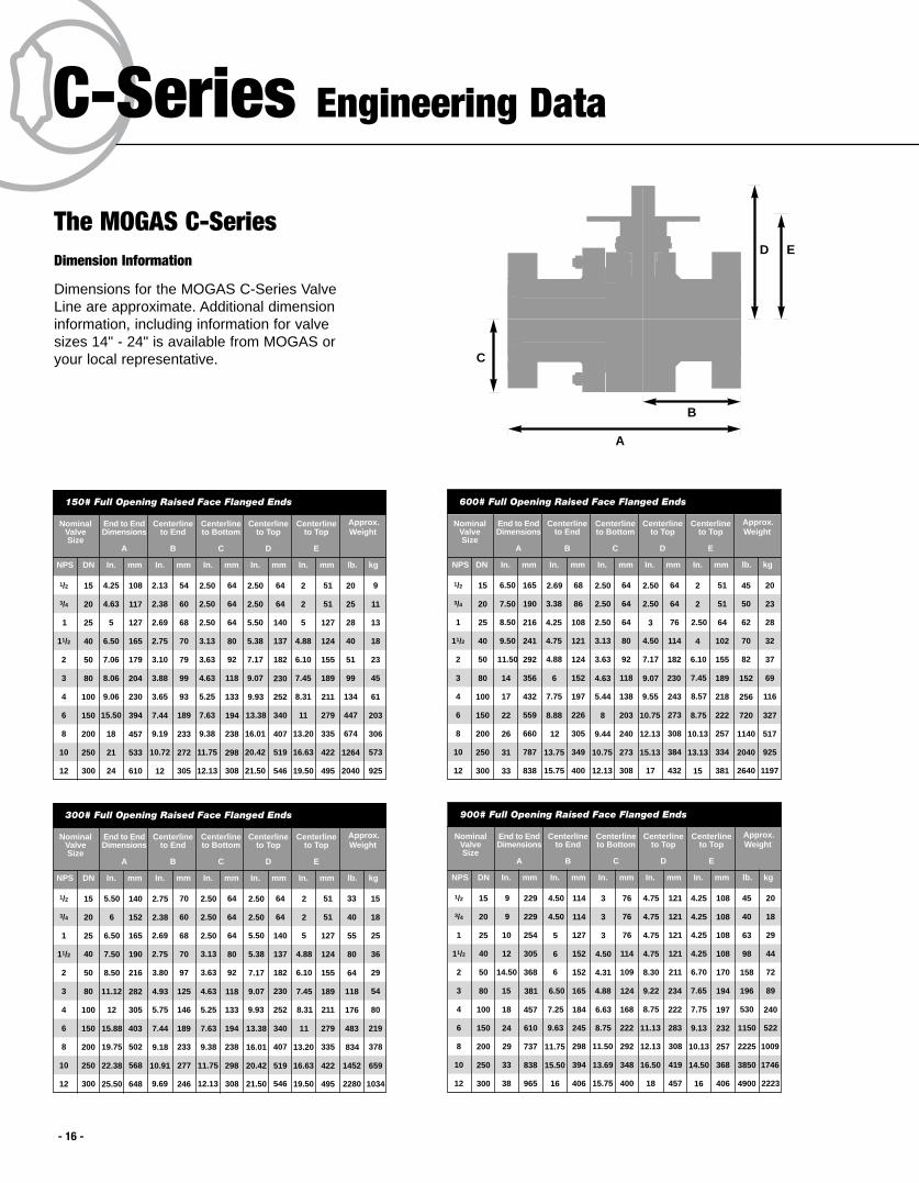
Dimension Information
Dimensions for the MOGAS C-Series ValveLine are approximate. Additional dimensioninformation, including information for valvesizes 14" - 24" is available from MOGAS oryour local representative.
NominalValveSize
NPS DN
End to EndDimensions
A
In. mm
Centerlineto End
B
In. mm
Centerlineto Bottom
C
In. mm
Centerlineto Top
D
In. mm
150# Full Opening Raised Face Flanged Ends
1/2
3/4
1
11/2
4.25
4.63
5
6.50
2.13
2.38
2.69
2.75
2.50
2.50
2.50
3.13
2.50
2.50
5.50
5.38
2
4
6
8
10
12
7.06
9.06
15.50
18
21
24
3.10
3.65
7.44
9.19
10.72
12
3.63
5.25
7.63
9.38
11.75
12.13
7.17
9.93
13.38
16.01
20.42
21.50
20
25
28
40
51
134
447
674
1264
2040
Centerlineto Top
E
In. mm
2
2
5
4.88
6.10
8.31
11
13.20
16.63
19.50
3 8.06 3.88 4.63 9.07 997.45
Approx.Weight
lb. kg
15
20
25
40
50
100
150
200
250
300
80
108
117
127
165
179
230
394
457
533
610
204
54
60
68
70
79
93
189
233
272
305
99
64
64
64
80
92
133
194
238
298
308
118
64
64
140
137
182
252
340
407
519
546
230
51
51
127
124
155
211
279
335
422
495
189
9
11
13
18
23
61
203
306
573
925
45
NominalValveSize
NPS DN
End to EndDimensions
A
In. mm
Centerlineto End
B
In. mm
Centerlineto Bottom
C
In. mm
Centerlineto Top
D
In. mm
600# Full Opening Raised Face Flanged Ends
1/2
3/4
1
11/2
2
4
6
8
10
12
Centerlineto Top
E
In. mm
3
Approx.Weight
lb. kg
15
20
25
40
50
100
150
200
250
300
80
165
190
216
241
292
432
559
660
787
838
356
68
86
108
121
124
197
226
305
349
400
152
64
64
64
80
92
138
203
240
273
308
118
64
64
76
114
182
243
273
308
384
432
230
51
51
64
102
155
218
222
257
334
381
189
20
23
28
32
37
116
327
517
925
1197
69
2.50
2.50
2.50
3.13
3.63
5.44
8
9.44
10.75
12.13
4.63
2
2
2.50
4
6.10
8.57
8.75
10.13
13.13
15
7.45
45
50
62
70
82
256
720
1140
2040
2640
152
2.50
2.50
3
4.50
7.17
9.55
10.75
12.13
15.13
17
9.07
6.50
7.50
8.50
9.50
11.50
17
22
26
31
33
14
2.69
3.38
4.25
4.75
4.88
7.75
8.88
12
13.75
15.75
6
NominalValveSize
NPS DN
End to EndDimensions
A
In. mm
Centerlineto End
B
In. mm
Centerlineto Bottom
C
In. mm
Centerlineto Top
D
In. mm
900# Full Opening Raised Face Flanged Ends
1/2
3/4
1
11/2
2
4
6
8
10
12
Centerlineto Top
E
In. mm
3
Approx.Weight
lb. kg
15
20
25
40
50
100
150
200
250
300
80
229
229
254
305
368
457
610
737
838
965
381
114
114
127
152
152
184
245
298
394
406
165
76
76
76
114
109
168
222
292
348
400
124
121
121
121
121
211
222
283
308
419
457
234
108
108
108
108
170
197
232
257
368
406
194
20
18
29
44
72
240
522
1009
1746
2223
89
45
40
63
98
158
530
1150
2225
3850
4900
196
4.75
4.75
4.75
4.75
8.30
8.75
11.13
12.13
16.50
18
9.22
9
9
10
12
14.50
18
24
29
33
38
15
4.50
4.50
5
6
6
7.25
9.63
11.75
15.50
16
6.50
3
3
3
4.50
4.31
6.63
8.75
11.50
13.69
15.75
4.88
4.25
4.25
4.25
4.25
6.70
7.75
9.13
10.13
14.50
16
7.65
NominalValveSize
NPS DN
End to EndDimensions
A
In. mm
Centerlineto End
B
In. mm
Centerlineto Bottom
C
In. mm
Centerlineto Top
D
In. mm
300# Full Opening Raised Face Flanged Ends
1/2
3/4
1
11/2
2
4
6
8
10
12
Centerlineto Top
E
In. mm
3
Approx.Weight
lb. kg
15
20
25
40
50
100
150
200
250
300
80
140
152
165
190
216
305
403
502
568
648
282
70
60
68
70
97
146
189
233
277
246
125
64
64
64
80
92
133
194
238
298
308
118
64
64
140
137
182
252
340
407
519
546
230
51
51
127
124
155
211
279
335
422
495
189
15
18
25
36
29
80
219
378
659
1034
54
5.50
6
6.50
7.50
8.50
12
15.88
19.75
22.38
25.50
11.12
2.75
2.38
2.69
2.75
3.80
5.75
7.44
9.18
10.91
9.69
4.93
2.50
2.50
2.50
3.13
3.63
5.25
7.63
9.38
11.75
12.13
4.63
33
40
55
80
64
176
483
834
1452
2280
118
2.50
2.50
5.50
5.38
7.17
9.93
13.38
16.01
20.42
21.50
9.07
2
2
5
4.88
6.10
8.31
11
13.20
16.63
19.50
7.45
E
The MOGAS C-Series
- 16 -

- 17 -
NominalValveSize
NPS DN
End to EndDimensions
A
In. mm
Centerlineto End
B
In. mm
Centerlineto Bottom
C
In. mm
Centerlineto Top
D
In. mm
2500# Full Opening RTJ Flanged Ends
1/2
3/4
1
11/2
2
4
6
8
10
12
Centerlineto Top
E
In. mm
3
Approx.Weight
lb. kg
15
20
25
40
50
100
150
200
250
300
80
229
229
254
305
454
683
927
1038
1292
1444
584
114
114
127
152
188
273
372
416
518
578
283
76
76
76
114
158
200
279
337
337
470
213
121
121
121
203
230
334
391
719
716
716
294
95
95
95
152
189
257
314
643
614
614
245
29
34
42
65
104
397
953
1588
2132
2359
204
9
9
10
12
17.87
26.88
36.50
40.87
50.88
56.88
23
4.50
4.50
5
6
7.41
10.75
14.63
16.38
20.38
22.75
11.13
3
3
3
4.50
6.13
7.88
11
13.25
13.25
18.50
8.37
3.75
3.75
3.75
6
7.45
10.13
12.38
25.30
24.19
24.19
9.63
65
75
92
143
230
875
2100
3500
4700
5200
450
4.75
4.75
4.75
8
9.05
13.13
15.38
28.30
28.19
28.19
11.59
NominalValveSize
NPS DN
End to EndDimensions
A
In. mm
Centerlineto End
B
In. mm
Centerlineto Bottom
C
In. mm
Centerlineto Top
D
In. mm
4500# Grayloc Ends
1/2
3/4
1
11/2
2
4
6
8
10
12
Centerlineto Top
E
In. mm
3
Approx.Weight
lb. kg
15
20
25
40
50
100
150
200
250
300
80
264
273
254
305
451
673
914
1022
1143
1257
584
132
137
127
152
226
337
457
511
552
524
241
76
76
76
114
143
292
330
337
337
470
238
121
121
210
216
216
546
643
716
716
716
394
95
95
184
191
165
470
567
640
614
614
289
36
45
68
113
168
544
1270
1905
N/A
N/A
202
3
3
3
4.50
5.63
11.50
13
13.25
13.25
18.50
9.38
3.75
3.75
7.25
7.50
6.50
18.50
22.31
25.19
24.19
24.19
11.38
80
100
150
250
370
1200
2800
4200
N/A
N/A
445
4.75
4.75
8.25
8.50
8.50
21.50
25.31
28.19
28.19
28.19
15.50
10.38
10.75
10
12
17.75
26.50
36
40.25
45
49.50
23
5.19
5.38
5
6
8.88
13.25
18
20.13
21.75
20.63
9.50
31
48
195
519
353
788
2101
4250
3177
7349
5947
13794
150# 300# 600# 900# 1500# 2500# 4500#Valve Size
1 x 3/4
11/2 x 1
3 x 2
4 x 3
6 x 3
6 x 4
8 x 6
10 x 8
12 x 8
12 x 10
14 x 10
14 x 12
16 x 12
16 x 14
18 x 12
18 x 14
20 x 14
20 x 16
24 x 20
9301
19917
7571
13591
11010
18879
32666
31
48
195
519
353
788
2101
4250
3177
7349
5947
13794
9301
19917
7725
14080
11242
19553
33793
31
48
195
519
353
788
2162
4502
3258
7778
6278
15502
10013
23041
8074
15242
12068
22079
39620
41
54
206
549
361
830
2376
4992
3511
9269
6983
19582
11487
30124
8735
17642
13151
25726
48754
41
54
218
632
377
917
7815
6247
3948
12411
8592
19466
14864
25787
10228
24039
15594
35175
70991
29
81
333
1071
457
1516
4641
7561
6623
10881
13347
13347
—
—
—
—
—
—
—
40
81
312
968
406
1095
3053
7018
4138
13955
9071
18818
—
—
—
—
—
—
—
Reduced Bore Cv Information
Valve Size
1/2
3/4
1
11/2
2
21/2
3
4
6
8
10
12
26
62
114
271
498
799
1176
2159
5076
9300
14866
21800
150# 300# 600# 900# 1500# 2500# 4500#*
26
62
114
271
498
799
1176
2159
5076
8985
14096
20857
26
52
85
223
432
640
1071
2014
4641
8120
12966
18579
20
33
62
145
271
432
640
1071
2603
4641
7561
10881
26
52
85
223
432
640
978
1749
4019
7023
11289
16045
6
19
38
140
271
385
670
1305
3309
6634
10565
15262
Full Bore Cv Information
26
62
114
271
498
799
1176
2159
5076
9300
14866
21800
* The CV information for the 4500# is based upon the inside diameter of the pipe schedule, while the remaining values are based upon ASME 16.34.
Cv information is approximate. Please contact MOGAS or your local representative for additional valve sizes.
Cv InformationNominal
ValveSize
NPS DN
End to EndDimensions
A
In. mm
Centerlineto End
B
In. mm
Centerlineto Bottom
C
In. mm
Centerlineto Top
D
In. mm
1500# Full Opening Raised Face Flanged Ends
1/2
3/4
1
11/2
2
4
6
8
10
12
Centerlineto Top
E
In. mm
3
Approx.Weight
lb. kg
15
20
25
40
50
100
150
200
250
300
80
203
216
254
330
368
546
705
832
991
1130
470
114
83
102
127
152
236
292
375
429
629
178
76
N/A
102
89
109
181
254
318
394
362
143
121
121
121
203
211
314
495
508
610
660
241
95
95
99
178
170
238
375
419
533
559
200
29
32
34
52
72
293
635
1043
1724
2041
166
8
8.50
10
13
14.50
21.50
27.75
32.75
39
44.50
18.50
3.75
3.75
3.88
7
6.70
9.38
14.75
16.50
21
22
7.88
65
70
75
115
158
645
1400
2300
3800
4500
365
4.75
4.75
4.75
8
8.30
12.38
19.50
20
24
26
9.50
4.50
3.25
4
5
6
9.31
11.50
14.75
16.88
24.75
7
3
N/A
4
3.50
4.31
7.13
10
12.50
15.50
14.25
5.63
- 18 -
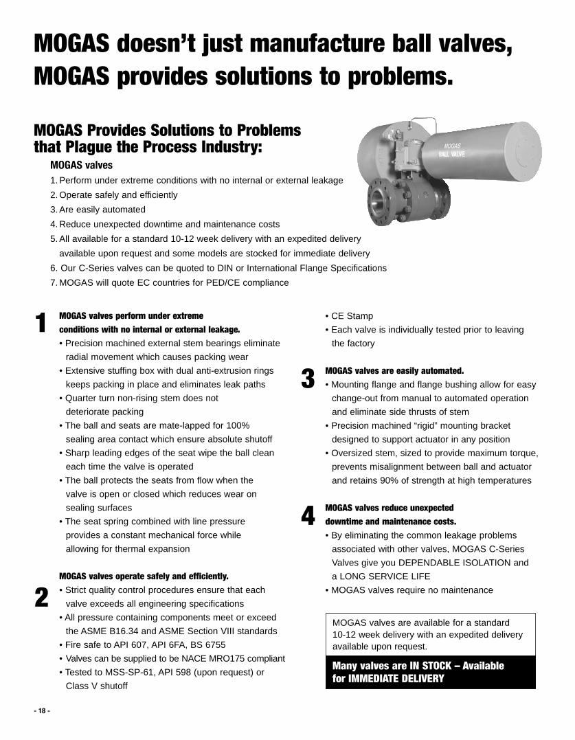
MOGAS Provides Solutions to Problems that Plague the Process Industry:
MOGAS valves1. Perform under extreme conditions with no internal or external leakage
2. Operate safely and efficiently
3. Are easily automated
4. Reduce unexpected downtime and maintenance costs
5. All available for a standard 10-12 week delivery with an expedited delivery
available upon request and some models are stocked for immediate delivery
6. Our C-Series valves can be quoted to DIN or International Flange Specifications
7. MOGAS will quote EC countries for PED/CE compliance
MOGAS valves perform under extreme conditions with no internal or external leakage.• Precision machined external stem bearings eliminate
radial movement which causes packing wear
• Extensive stuffing box with dual anti-extrusion rings
keeps packing in place and eliminates leak paths
• Quarter turn non-rising stem does not
deteriorate packing
• The ball and seats are mate-lapped for 100%
sealing area contact which ensure absolute shutoff
• Sharp leading edges of the seat wipe the ball clean
each time the valve is operated
• The ball protects the seats from flow when the
valve is open or closed which reduces wear on
sealing surfaces
• The seat spring combined with line pressure
provides a constant mechanical force while
allowing for thermal expansion
MOGAS valves operate safely and efficiently.• Strict quality control procedures ensure that each
valve exceeds all engineering specifications
• All pressure containing components meet or exceed
the ASME B16.34 and ASME Section VIII standards
• Fire safe to API 607, API 6FA, BS 6755
• Valves can be supplied to be NACE MRO175 compliant
• Tested to MSS-SP-61, API 598 (upon request) or
Class V shutoff
1
2
3
4
• CE Stamp
• Each valve is individually tested prior to leaving
the factory
MOGAS valves are easily automated.• Mounting flange and flange bushing allow for easy
change-out from manual to automated operation
and eliminate side thrusts of stem
• Precision machined “rigid” mounting bracket
designed to support actuator in any position
• Oversized stem, sized to provide maximum torque,
prevents misalignment between ball and actuator
and retains 90% of strength at high temperatures
MOGAS valves reduce unexpected downtime and maintenance costs.• By eliminating the common leakage problems
associated with other valves, MOGAS C-Series
Valves give you DEPENDABLE ISOLATION and
a LONG SERVICE LIFE
• MOGAS valves require no maintenance
MOGAS doesn’t just manufacture ball valves,MOGAS provides solutions to problems.
MOGAS valves are available for a standard10-12 week delivery with an expedited deliveryavailable upon request.
Many valves are IN STOCK – Availablefor IMMEDIATE DELIVERY
A partial list of satisfied MOGAS customers include:
• Chemical/PetrochemicalAir ProductsDow ChemicalE.I. Dupont Eastman ChemicalGB BiosciencesHanwha Chemical
• RefiningBP/AmocoChevronExxon/MobilMotivaPemexSyncrude
MOGAS engineers and manufactures severe servicemetal seated ball valves for a wide range of specificindustries and applications including:
• PowerBoiler Drain IsolationControl Valve IsolationFeedwater Heater IsolationMain Steam IsolationOverpressure Relief of Boiler /
Superheater HeaderSteam Drum Vent Isolation
• MiningAutoclave Vent Isolation and ShutdownAutoclave Discharge IsolationSlurry Transport
• Specialty Applications:MOGAS has extensive experience in servingthe needs of miscellaneous specialty applications. If your application is severe, temperatures up to 1652°F (907°C), pressuresup to 30,000 psig and has erosive/corrosive media, MOGAS can engineer a valve that will perform under harsh conditions with zero leakage.
• Hot Gases• Supercritical CO2 Extraction• Food Processing• Coal Liquification/Gasification• DRI• Iron Carbide• Pulp and Paper
The MOGAS definition of SEVERE SERVICE:• High temperature—up to 1,652˚F• High pressure—up to 30,000 psig• Entrained or abrasive media• Corrosive media
MOGAS Industries, Inc.14330 East Hardy StreetHouston, TX 77039-1405
Phone: 281.449.0291 Fax: 281.590.3412E-mail: [email protected]
www.mogas.com
© 2004-4 MOGAS Industries, Inc.