best available cop
TRANSCRIPT

,L-T-94-3077 Best Available CopLARGE AMPLITUDE NONLINEAR RESPONSEOF FLAT ALUMINUM, AND CARBON FIBER BEAMS AND
ADlmA282 440
HOWARD F. WOLFECYNTHIA A. SHROYER
JUNE 1994
INTERIM REPORT FOR 10/01/92-09/01/93
APPROVED FOR PUBLIC RELEASE; DISTRIBUTION IS UNLIMITED.
OTIClma LECTE
JUL 211994
G "D
94-22589
FLIGHT DYNAMICS DIRECTORATEWRIGHT LABORATORYAIR FORCE MATERIEL COMMANDWRIGHT PATTERSON AFB OH 45433-7562
Best Available 19py 7 ]L9' 075 "

NOTICE
When Government drawings, specifications, or other data are used forany purpose other than in connection with a definitely Government-relatedprocurement, the United States Government inzurs no responsibility or anyobligation whatsoever. The fact that the government may have formulated orin any way supplied the said dra,'i.is, specifications, or other data. is notto be regarded by implication, or otherwise in any manner construed, aslicensing the holder, or any other person or corporation; or as conveyingany rights or permission to manufacture, use, or sell any patented inventionthat may in any way be related thereto.
This report is releasable to the National Technical Information Service(NTIS). At NTIS, it will be available to the general public, includingforeign nations.
This technical report has bean reviewed and is approved for publica-tion.
Howard F. Wolfe, Aerdspace Engineer Cynthia K. Shroyer, ComputerAcoustics & Sonic Fatigue Section Scientist, Data Analysis Section
Coordination:
Ra p M. Shimovetz, Tech Manager J n T. Ach, Tech ManagerAcoustics & Sonic Fatigue Section Data Analysis Section
Js . MoschlerStructural Dynamics BranchStructures Division
If your addr 3s has changed, if you wish to be removed from ourmailing list, or if the addressee is no longer employed by yourorganization, please notify WL/FIBGD, Wright-Patterson AFB, OH 45433-6553 to help maintain a current mailing list.
Copies of this report should not be returned unless return isrscquired by security considerations, contractual obligations, ornotice on a specific document.

I31 LAIMEI NOTICE
* 118DOCUMEN IS BESTQUALITY -AVAILABLE H COPY
FCEISEDTO DTI CONTAINE
A SIGNIFCANT NUMBE OFPGES WHCH DO NOT
REPODUC LGIBLY.

"'- a - . ,,--T'--" .- ,.. aT ' mmsatr'..cm 0m t ?m~ "u't
A 2L &°. sL T t OtaAJ a.DOOar OFATS lUOUT TYM AlPC hm " 00"11,
....., NSE OF FLAT ALUI , 622ANDT- .B I -XCi'OKCe3 PLASTIC-BEAMS AND PLATES________Project: 2 01
Task: 0i4
Work Unit: 42L ard 7. L)11., Cynthia A. Shroyar
4 M'0CAdM4 _$AFAD D~a SS 70 IL PIRFOAAMG OACAZATKI.4RIMRT hM'X
Tlight Dynanct DirectoretoV ,ri-ht orty
W113 ORl44~-,5
AGENY ItUPMR VGWAStf2T ,C T DYNA2IICS DIRECTORATE
'5UlCdT 30PAT0lYATR FORCE MTE. EL CO14HANID WL-T-94-3077
WliiCT PA'fTERS0 AFB Oil 45433-7562
271cT.E~C:AV~-~l'M~ 12b. 04SRJUT11OJ COD2
Akproved for 1A!!Aic rcleaae; distribution is unlimited.
Thia proare report presents tha results of a continuing study to improve theunderntandid of nonlinear dynamic behavior of aerospace structures subjected to
bigh levels oZ excltntion. Tests were continued with ablamped-clamped
(C-C) altuminum bcaz. A suvmary of the results is presented. Tests were conductedwith I C-C carbo. r-b-r reinforced plastic (CFRP) beam and a pinned-pinned (P-P)altrninum bcm. A tt6ary of these results is also presented. Flat plate tests
began with in alamjun plate. Th* shapes of the total, axial and bending strainI povar 3peet:ral d;naitJ.eS for the C-C aluminum and the CFRP beams were quite
sinlat. Eoth 3>-0ed a small frequency increase and slight peak broadening as the
lev'111 of cxcita fin increased. The nonlinear displacement shapes for the two ceaeswovrn P:lso suite 4lilar. Further analysis is needed for the P-P aluminum beam
ci :~. ?J.nilly, wathod of ctimating the RHS s~tress for the multimodal responsep. antl la preoentid.
15. NUMB[R Of PACES
'orn lingar blvt-ton, nonLC fatigue, clatnped bcamn, clamped 90q t]L t , yntv,,,c to., tirig , dynnmic analysisi. 16. rRICI C001
' 1TY 0 VULSST ICAION 19. ' (URITY CLASSIICATION 20. LCFDYATIONO ASTRACTnol .U ic~ !W PAG: Of A CTMRAC7
V-74' Tf'wLTAS!SIFTD J ICLASSIFIED U

Th F:o ~~crtprz,,onts the results of a continuinuct~ ~ eunderstan.ding of nonlinear dynamic bjihaviora
) ~c~:,.t2c~u~isubje~cted to high levels of excitation.~ ~oti; cd with a Continued clamped-clamped (C-C)
\ -UA z" sum.,ftiry of the results is presented. Tests:c cond-,cted ~iia C-C carbon f iber reinforced plastic (CFII')
,i A2ined-nrnnedi (P-i?) aluminum beam. A summary of thes-e--t 13. Ul o ,,:esente d. Flat plate tests began with an
~ 'l~t. >h~shapes of the total, axial and bendingp0. e. ~p ~ dL1 cnsities for the C-C aluminum and the CFRP?
~ ~u~te iiiar. Both showed a small frequency increaseIi;~ ieak b::ozd2ning as the levels of excitation increased.
-,onlinear dL,-placea~ont shapes for the two cases were also-s niieir. L! rthcr analysis is needed for the P-P aluminuiiScase. Fina..2.y, a method of estimating the RMS stress for
*ultu~-a' rp n, 0f a panel is presenlted.
... ult iol rc __on1

CON'TENTS
IONPAGE
I INTRODUC ION . . . . . . . . . . . . . . . . . 1
3EAM TEST RIG 13 CLAMPED-CLAMPED (C-C) ALUMINUM
BM EXPERIMENTS .............. 2
CLAMPED-CLAMPED (C-C) CARBON FIBER REINFORCEDPLASTJIC (CFRP) BEAM DYNAMIC TESTS . . . . . 3
5 PINNED-PINNED (P-P) ALUMINUM BEAM DYNAMIC TESTS . . 4
6 LARGE AMPLXTUDE DISPLACEMENT SHAPES AND ANALYSIS . 5
7 MAGNETIC FIELD EFFECTS ON STRAIN GAUGE MEASUREMENTS 7
8 CLAMPED-CLAMPED (C-C) ALUMINUM SHAKER TEST PANEL . 8
9 CARBON FIBER REINFORCED PLASTIC (CFRP) SHAKER TESTPANELS . . . . . .
10 F7NITE ELEMENT METHODS (FEM) ........... 8
11 RECTANGULAR PLATES UNDER LARGE DEFLECTIONS . . . .
12 ESTIMATING MULTIMODAL RANDOM RESPONSE OF PLATES . . . 9
13 COCLUSIONS . . . . . . . . . . . . . . 10
14 REFERENCES ............ . . .. . . . .
TABLC I .............................. 12
Acceslon ForNTIS CRA&IDTIC TABUnannouncedJustification_
Distribution IAvailability Codes
Dit Avail and/orDist Special
±±±4

LIST OF FIGURES
PAGE1. BEAM TEST RIG, CLAMPED-CLAMPED (C-C) FIBER REINFCI.CZD
PLASTIC (CRP) BA ...... 13
2 STATIC DrLmCTIoN SHAPES FOR C-C ALUMINUM BEAM . .. 14
3 STATIC DEFLECTION SHAPES, EDGE EFFECTS, C-C ALUMINUM BEAM 15
STRAIN GAUGE LOCATIOn1S, ALUMINUM BEAM . ...... 16
S STATIC TENSION TEST, CLAMPING BLOCK 20mm FROM SG 3&6, C-CALUM Ik 4 BEAM . . . . . . . ................... 17
c, STATIC TENSION TEST, CLAMPING BLOCK 1mm FROM SG 3&6, C-CALUMINUMIN A BEA . ...................... . . . . 18
7 STATIC EEDING TEST, C-C ALUMINUH BEAM . . . . . . . . . 19
TOTAL, BINDING AND AXIAL STRAINS, 10-400 HZ RANDOM, C-CALUMINUM BEAM ...... . . . . . . . . . . . . . . . 20
9 TOTAL, BENDING AND AXIAL STRAINS, SINE DWELL, C-C ALUMINUMBEAM . . . . . . . . . . . . . . . . . . . . . . . . . . 21
10 STRAIN VS DISPACMENTr SINE DWELL, C-C ALUMINUM BEAM . 22(
11 ILOW FREQUENCY SWEEP, C-C ALUMINUM BEAM . . ........ 23
il FTATIC TENSION TEST, CLAMPING BLOCK 20mm FROM SG 3&6, C-CClRP BEAM ....... ................. . . . . . . 24
13 STOIC TENSION TEST, CLAMPING BLOCK 1mm FROM SG 356, CFRPB . . . . . ..................... . . . . 25
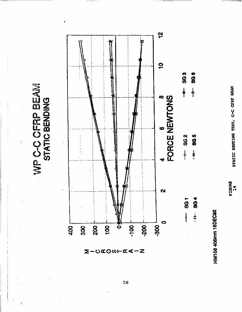
14 STATTEBMINGTZST, C-C CFRP BEAM..... . . . . . . 26
5 STATIi DISPLACEMENT VS STRAIN, C-C CPRP BEAM . . . . . . 27
1.6 CURR1+ VS DISPLACEM-NT AND STRAIN, SINE DWELL, C-C CFRPB.M . . ................. 28
27 CURREtVS TOTAL STRAIN, SINE DWELL, CFRP BEAM ...... .. 29
18 CtRPE1 'S AXIAL STRAIN, SINE DWELL, CFRP BEAM ..... 30
19 DSPLACMNT;VS STRAIN, SINE DWELL, CFRP BEAM ... ..... 31
20 FREQUENCY SWJ.EP, J1R43 EFFECT OF FIRST MODE, C-C CFRP BEAM 32
21 DISTOREDJDISPl CF&qENT SHAPE, THIRD MODE, 388.6 HZ CFRPBEAM ........ ... .......................... 33
iv

22 DISTORTED DISPLAEMM SHAPE, THIRD MODE, 406.7 KZ, CFRPB E M . . . . . . . . . . . . . . . . . . . . . . . . 3 4
23 DISTORTED DISPLACEMENT SHAPE, FIFTH MODE, 1028.4 HZ, CFRPB .M ............. ......................... 35
24 STRAIN SPECTRAL DENSITIES, SG 1, 10-1300 HZ RANDOM, C-C CyRPBEAM . . . . . . . . . . . . . . . . . . . . . . . . . . 36
25 STRAIN SPECTRAL DENSITIES, SO 2, 10-1300 HZ RANDOM, C-C CFRPBEAM ........... .......................... 37
26 STRAIN SPECTRAL DENSITIES, SG 3, 10-1300 HZ RANDOM, C-C CFRPBEAM ........ .................... . . . . . . 38
27 DISPLACEMENT SPECTRAL DENSITIES, BEAM CENTER, 10-1300 HZRANDOM, C-C CFRP BEAM ..... .............. . .. 39
28 CURRENT SPECTRAL DENSITIES, 10-1300 HZ RANDOM, C-C CFRPBEM . . . . . . . . . . . . . . . . . . . . . . . . 40
29 CURRENT VS DISPLACEMENT AND STRAIN, 10-600 HZ RANDOM, C-C
ClPP BEAM .................................. 41
30 BEAM TEST RIG, PINNED-PINNED (P-P) ALUMINUM BEAM . ... 42
31 P-P ALUMINUM BEAM AND FIXTURE DESIGN ... .......... 43
32 P-P ALUMINUM BEAM STATIC BENDING TEST .'.... . . .. 44
33 CURRENT VS DISPLACEMENT AND STRAIN, P-P ALUMINUM BEAM 45
34 INCREASING FREQUENCY SWEEP, JUMP EFFECT OF FIRST MODE, P-PALUMINUM BEAM ......................... 46
35 DECREASING FREQUENCY SWEEP, JUMP-UP EFFECT OF FIRST MODE, P-P ALUMINUM BEAM . . ................... . . . 47
36 DECREASING AMPLITUDE SWEEP, JUMP-DOWN EFFECT, FIRST MODE, P-P ALUMINUM BEAM ........ .................... 48
37 DECREASING AMPLITUDE SWEEP, JUMP-UP PHENOMENA, FIRST MODE,P-P ALUMINUM BEAM ....... ................ . . . 49
38 TOTAL STRAIN SPECTRAL DENSITIES, SG 1, 10-1000 HZ RANDOM, P-P ALUMINUM BEAM ........ ................... 50
39 TOTAL STRAIN SPECTRAL DENSITIES, SG 2, 10-1000 HZ RANDOM, P-P ALUMINUM BEAM ........ .................... 51
40 AXIAL STRAIN SPECTRAL DENSITIES, SG 1 10-1000 HZ RANDOM, P-PALUMINUM BEAM ........... ..................... 52
V

41 BENDING STRAIN SPECTRAL DENSITIES, SG 1&4, 10-1000 HZRANDOM, P-P ALUMINUM BEAM .............. 53
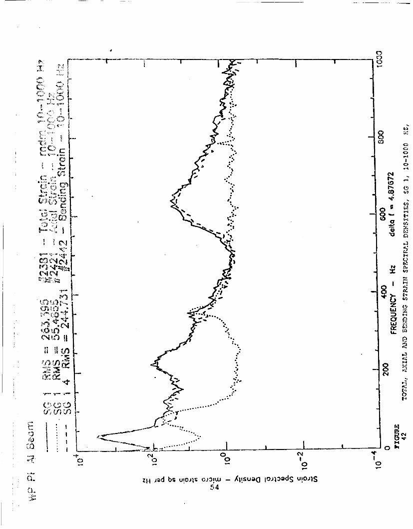
4,'2 TOTAL, XIAL AND BENDING STRAIN SPECTRAL DENSITIES, SG 1,10-1000 HZ, P-P ALUMINUM BEAM .... ............. 54
43 NONLINEAR DISPLACEMENT SHAPES, FIRST MODE, RAW DATA, C-Ci.LTUMINUM BEAM . . . . . . . . . . . . . . . . . . . . 55
4' NONLINEAR DISPLACEMENT SHAPES, THIRD MODE, SEVENTH ORDERPOLYNOMIAL FIT, C-C ALUMINUM BEAM ... ........... 56
45 FIRST MODE, SEVENTH ORDER POLYNOMIAL CURVE FIT, FIRSTDERIVATIVE, C-C ALUMINUM BEAM .... ............ 57
46 FIRST MODE, SEVENTH ORDER POLYNOMIAL CURVE FIT, SECONDDERIVATIVE, C-C ALUMINUM BEAM .... ......... . . . 58
47 NONLINEAR DISPLACEMENT SHAPES, FIRST MODE, FOURTH ORDERPOLYNOMIAL FIT, C-C ALUMINUM BEAM ... ........... 59
48 FIRST MODE, FOURTH ORDER POLYNOMIAL FIT, FIRST DERIVATIVE,C-C ALUMINUM BEAM ....... ................... 60
49' FIRST MODE, FOURTH ORDER POLYNOMIAL FIT, SECOND DERIVATIVE,C-C ALUMINUM BEAM .... ............. ..... . . . 61
50 NORMALIZED NONLINEAR DISPLACEMENT SHAPES, FIRST MODE, C-CALUMINUM BEAM .......... . . . . . . . . . . . . 62
51 MODE SHAPE, THIRD MODE, ACOUSTIC EXCITATION, C-C CFRPBEAM . .......... .......................... 62
52 NONLINEAR DISPLACEMENT SHAPES, FIRST MODE, RAW DATA, C-CCFRP BEAM .......... ....................... 63
53 NONLINEAR DISPLAC3MENT SHAPES, FIRST MODE, FOURTH ORDERPOLYNOMIAL, C-C CFRP BEAM ...... .............. 64
54 FIRST MODE, FOURTH ORDER POLYNOMIAL FIT, FIRST DERIVATE, C-CCFRP BEAM ............................. 65
55 FIRST MODE, FOURTH ORDER POLYNOMIAL FIT, SECOND DERIVATIVE,C-C CFRP BEAM ....... ................... .. 66
56 NORMALIZED NONLINEAR DISPLACEMENT SHAPES, FIRST MODE, C-CCFRP BEAM .......... ..................... 67
57 NONLINEAR DISPLACEMENT SHAPES, FIRST MODE, RAW DATA, P-P,ALUMINUM BEAM ........ ................... 68
58 NONLINEAR DISPLACEMENT SHAPES, FIRST MODE, FOURTH ORDERPOLYNOMIAL FIT, P-P ALUMINUM BEAM ... ........... 69
vi

59 FIRST MODE, FOURTH ORDER POLYNOMIAL FIT, FIRST DEF.IVATIVE,P -P ALUMI NUM B AM . . . . . . . . . .. . . . . 70
60 FIRST MODE, FOURTH ORDER POLYNOMIAL FIT, SECOND DE..iVATIVE,P-P ALUMINUZA BEAM .. .. .. .. .. .. .. .. . .. 71
61 NORMALIZED NONLINVEAR DISPLACMENT SHAPES, FIRST MODE, ?-PALUMINUM BEAM .................... 72
62 MODE SMLPE, 1:1, C-C ALUMINUM PLATE ........... 73
63 SKEWED MODE SHAPE, 3:1, C-C ALUMINUM PLATE ........ . 74
64 MODE SHAPE, 2:2, C-C ALUMINUM PLATE ...... .......... 75
65 SCEWED MODE SHAPE, 3:1, C-C ALUMINUM PLATE .. ....... .. 76
66 COMPARISON OF C-C ALUMINUM BEAM DEFLECTION TEST RESULTS WITHFEM RESULTS .. . . . . . . . . . . . . . . ....... 77
67 COMPARISON OF C-C ALUMINUM BEAM STRAIN TEST RESULTS WITH FEMRESULTS, NO PRELOAD ....................... 78
68 COMPARISON OF C-C ALUMINUM BEAM STRAIN TEST RESULTS WITH FEMRESULTS, WITH PRELOAD .................. 79
69 STATIC DEFLECTION VS STRESS, C-C PLATE, REF 3 RESULTS . 80
70 STATIC CURRENT VS STRAIN, C-C ALUMINUM BEAM TEST RESULTS 81
f -

FOREWORD
This memorandum summarizes the information contained in the MPhil!PhD Progress Report submitted in June 1993 to Professor R.G.White, Academic Supervisor, at the Institute of Sound and VibrationResearch (ISVR), University of Southampton, England. The work wasperformed under the supervision of Professor R. G. White and R. M.Shi ovetz, Technical Manager, Acoustics and Sonic Fatigue Section,Structural Dynamics Branch, Wright Laboratory, Wright-Patterson AirPorce Base (WPAFB). The initial work at ISVR, published in WL-TM-91-311-FIBG, has been continued at WPAFB. A second memorandmu waspublished, WL-TM-93-352-FIBG.
viii

wC
Thi; is the third memorandum summarizing the progress madeL A in-house research project entitled "Nonlinear Aspects ofrspace Structures at High Excitation Levels." The first and
iccnd memoraricta (I and 2] were published in May 1991 and_,( ccnber 1992. The goal of the project is to improve theunderstanding of the nonlinear dynamic behavior of aerospacestructures subjected to high excitation levels. Aluminum and__rhon fiber reinforced plastic (CFRP) beams and plates werej:tudied analytically and experimentally.
The test rig for testing the beams was modified to reducealignment problems when lightly tensioning the beams and clampingthe beams to the bed plate as shown in Fig 1. Steel blocks weremachined with protrusions to fit the grooves in the vibrationisolation bed plate. This change permitted static testmeasurements to be taken by applying a load axially to the beamwith the threaded rod assembly. One of the beam clamps was keptloose to allow movement and static tension loads to be placed on_,e beam. This method revealed errors in the strain gaugemeasurements close to the clamping block, as well as the othergauges and is discussed in the beam test sections of this report.
The annular permanent magnet mounting was changed when theforce produced by the coil in the magnetic field was found to benonlinear with coil travel. Originally, two magnets were mountedtogether which modified the magnetic field of the magnet beingused. The one magnet arrangement was found to be satisfactory.-'-w coil-magnet calibration curves were obtained relating thecoil current to force for sinusoidal and random excitation.
The strain bridge amplifiers that were used can be either ACcoupled or DC coupled. DC coupling was selected since the in-1JrAne stretching results in a DC offset or a mean value other
than zero in the strain time histories. The in-plane stretchingo)r axial strain was one of the primary effects of interest inthis study. Many sources of electronic errors can contaminatetho strain data when the bridges are DC coupled. Any DC offsetin the force excitation circuit can result in a DC shift in';train. Some possible sources are the band pass filter, currentmodifier, amplifier, strain bridge amplifier and recording3 ystem. Each source was carefully checked before the start of a
:ezt to eliminate electronic DC offsets.
A new consLant current modifier was designed and built torceplace the one developed at the Institute of Sound and Vibration<esearch (TSVR) The new modifier in combination with the new-rn!tant current amplifier provided a flatter narrow band random
1

*ut.spocttyur to excite the beams.
. CLA D-CL 4PZJ (C-C) ALU4INUM BF M4 EXPERIMENTS
Static deflection shapes were obtained by applying DC,eur:rent to the coil and measuring the displacements with a dialg ge. The resulcs, shown in Figs 2 and 3, will be useful in
'h:cking large displacement static bending theories.
Static strain gauge measurements were made and compared with6iia gauge measurements of the elongation of the beam. Thesevlues can be compared since the strain is equal to the amount ofelongation divided by the length of the beam (At/1). The strainauge locations are shown in Fig 4. Gauges 3 and 6, installed
back-to-back, were very close to the clamping block. Thisyielded erroneous data due to the clamping pressure applied to
me end of the beam and distortion of the bonding surface. The
active element of gauges 3 and 6 was 0.8128 mm in length and
mounted 1 mm from the clamp location to obtain data close to the
stress concentration. The torque values to tighten the clamping
r late were selected to prevent beam slippage. The clamping block
w s moved 19 mm from gauges 3 & 6 to determine accuracy and the
effect of clamping close to the gauges. Fig 5 shows the results
cL the tests. Although the gauge measurements were reasonably
linear, 4 out of 6 gauges were 30 microstrain below the 800
microstrain level, about 4 % accuracy. When the clamping block
was moved to 2 mm from gauges 3 & 6 (Fig 6) the results were
s.milar except for gauges 3 & 6. Gauges 3 & 6 were reasonably
linear but 34% low in level. Different adhesives, coatings,strain gauges and beams were evaluated with similar results. The
7: jor source of error was found to be the method of bonding thestrcain gauges to the beams. The static bending results, shown inF'g 7, show the nonlinear increase in strain as the static load
ilceases.
Total, axial and bending strain measurements were measured
again with random excitation at different load levels with a
variety of bandwidths to determine the effects of exciting the
following modes of vibration: first mode only, third mode only,
fifth mode only, first and third modes and first, third and fifth
modeas. These tests were conducted to study modal coupling
ez:f.-cts, if any. Preliminary results showed the modes well
ep<irated in frequency and no modal coupling. One example of the
totAl, axial and bending strain results is shown in Fig 8. Sine
dwtell tests were also conducted and are shown in Fig 9.
Displacements at the center of the beam were also measured
i,-.ing a laser vibrometer and sine dwell excitation as shown in1q 10. The besm was then excited with slow sine sweeps at low
j< 'ils to determine damping for the first mode using the half
ro,-r point bandwidth method. The following relationship was
2

d t1:ith the exciter coil attached to the beame the lossfictors rieasured were 1.89%, 1.85% and 1.92%. No measurabledifference in damping for the beam was found with or withoutretro-reflectlve laser tape used to lower noise in vibrometermeasurements. An example of a sine sweep is shown in Fig I.
* W Af
Displacement measurements of the clamping block were takenwith the vibrometer in the direction of beam motion. Only0.00305 mm peak-to-peak was measured with sinusoidal excitationof the first mode at a maximum level of 85 ma, 64.6 Hz, 230microstrain at the center of the beam, and 2.3 mm peak-to-peakdisplacement. The percent displacement of the block relative tothe beam peak displacement was only 0.133%, but the test was notperformed with a perfectly clamped boundary condition.
4. CLAMPD-CLAMPED (C-C) CARBON FIBER REINFORCED PLASTIC (CFRP)B DYNAMIC TESTS
The two CFRP beams fabricated, APC-2 Graphite/PEEK, werescrapped because distortion built up in the beams. Two moreattempts to fabricate thermoplastic beams were also unsuccessful.Fabrication of graphite epoxy beams (0*/±450/900)2, with HerculesAS4/3501-6 prepreg tape yielded flat beams suitable for testing.The dimensions were the same as the aluminum beams (2x20x631 mm)except the thickness was increased from 2 mm to 2.21 mm to obtaina symmetric ply lay-up.
Tests conducted on the graphite epoxy beam were similar topast tests for the aluminum beam using the same test rig. The
results from the static tension tests were similar for the twotypes of beams, however, the gauge measurements on the graphite
epoxy beam were about 100 microstrain lower at the 800microstrain level but still linear. Static tension test results
are shown in Fig 12 and 13. Static bending test results, shown
in Fig 14, were also similar to the aluminium beam results. The
displacement versus strain data are shown in Fig 15 for strain
gauges 1 & 3.
The sine dwell total, axial and bending strain anddisplacement data at high excitation levels are shown in Fig 16.
The peak frequency increased from 56.5 Hz to 75.3 Hz. The total
and axial strains for all 6 gauges are shown in Figs 17 and 18.
The axial strain for the gauges at the clamped edge for the
maximum load case was about 65 microstrain, whereas, the other
gauge locations were about 75 microstrain. This amounts to 14%
lower measurement than the other locations, otherwise, the axial
strains were about equal for all excitation loads. The strain
3

v. x:sj. displacement data are shown in Fig 19.
For the frequency sweep tests, the frequency was slowly-:21 from 1o; to high and high to low for the first mode of
.' oation to determine the jump characteristics. An example is;Yw in Fig 20. Likewise, amplitude effects at three differentf:equencies were determined by slow amplitude sweeps from low to: .-Sine sueeps were also recorded to determine the first moded::. ping.
Locating the third and fifth modal frequencies was moredifficult than the first. Two distorted third modes appeared at308.6 Hz and 406.7 Hz as shown in Figs 21 and 22. At the lowerfrequency the left peak was much higher than the right and at thehigher frequency, the opposite was true. The coil and beamtorsional resonances were at 2200 Hz and above, so they weredismissed as sources of contamination and coupling. The plasticz;crew attaching the coil to the beam was machined to align thecoil more nearly perpendicular to the beam. This resulted in thehigher frequency, 406.7 Hz, being more predominant although thelower frequency third mode still appeared. The instance of twothird modes did not occur with the same test rig for the aluminumoeam case. One explanation is the possibility that the compositematerial properties, which were not present in the C-C aluminumcase, may result in distortion in the higher mode of vibration.Likewise, the fifth mode was also distorted as seen in Fig 23.More examples of this phenomena can be seen from the randomexcitation plots in Figs 24 through 28.
Two bandwidths were selected for the random tests, 10 - 600HAZ and 10 - 1300 Hz. The power spectral densities for the 10 -1300 Hz cases for three strain gauge locations are shown in Figs24, 25, and 26. The displacement and current power spectraldensities are shown in Figs 27 and 28. The first mode had onepeak at all levels of excitation as did the first mode for thealuminum beam. The third and fifth modes each occurred at twodifferent frequencies at strain locations 2 and 3 as shown inrigs 25 and 26. The fifth mode peaks were not symmetric. Thelower of the two frequencies shifted to lower frequencies at higheyxcitation levels which is characteristic of a soft springnonlinearity. The power spectral densities for the displacementsa:re shown in Figure 27. The double peak phenomenon for the thirdand fifth modes was not apparent since the displacements at thece nler of the beam were much smaller than those for the firstrode. The power spectral densities for the current are shown inFiq 28. The total, axial and bending strains for thedisplacement in the 10 - 600 Hz random case are shown in Fig 29.
PI5W.D-PNM4E) (P-:) ALJUINUM BEAM DYNAMIC TESTS
A pinned-pinned beam and fixture were fabricated and
4

installed in the test rig as shown in Figs 30 and 31' A longereciter coil was also fabricated in order to maintain a linearcurrent-force relationship since the displacements were muchhigher for the P-P case than the C-C case. The mass of the new;oil assembly was 66 g, 39,6 g heavier than the coil assembly fort>o C-C case. The current modifier was changed to handle thehigher currents required.
The static bending test results are shown in Fig 32. Thedisplacement data are shown with the strain data in Fig 33.
The frequency was repeatedly swept from low to high and highto low for the first mode using increasly higher force levels inorder to observe the jump phenomenon (Figs 34 and 35). FivefErequencies were selected around the first mode and theamplitudes were slowly increased and decreased (amplitude sweeps)as shown in Figs 36 and 37. These sweeps describe the twobistable states in which the beam vibrates.
Combined plots of the strain spectral densities for thetotal strain at gauge locations 1 and 2 are shown in Figs 38 and39 for the random excitation tests. The axial and bending strainspectral densities are shown in Figs 40 and 41. A comparison ofthe total, axial and bending strain spectral densities for gaugelocation 1 is shown in Fig 42.
6. YIAiO AMLITUDK DISPULCEMENT SEAPZS AND ANALYSIS
Nonlinear displacement shapes were obtained experimentallyfor two clamped-clamped beams, an aluminium one and a CFRP one,and one pinned-pinned aluminium beam by sinusoidally excitingth;.., at large amplitudes of vibration. These experiments wereconducted as part of a study to more fully understand nonlineareffects in, sonic fatigue analysis of structures. Many recentadvances have been made in'the technology of scanning laserdoppler sensors. The rapid scanning capability as well asautomatic data collection and display methods are particularlyadvantageous in measuring mode shapes and large amplitude surfacevelocities. The upper velocity limit of 1 m/s has recently beenincreased to 10 m/s, which facilitates the measurement ofdisplacement shapes to very high amplitudes with a high degree ofaccuracy. The inherent accuracy of these sensors is due to thesmall wavelength of the light beam. These capabilities plus manyother features have made the scanning laser doppler sensor veryfavorable for obtaining experimental displacement data for highamplitude vibration of beams, as well as many other structures ofinterest.
Nonlinear displacement shapes are dependent upon theexcitation force and the tuning frequency. This differs frommode shapes which are mathematically linear, amplitude

ndont -nd occ.u- at a aingla frequency. The nonlinoar' : .v~or bitcd chaacteriotics similar to a cubic stiffnov
-A% tho cq%=tion oqf motion.
,:ha surface vlocity measurements from the scanning lacsr1-]:cv tor were electronically integrated to yield displacemontu '.' The b ama wero sinusoidally excited from low to high to
3x. one rosonant frequency in the nonlinear region ofonse. A second frequency was also obtained when the
< :z ~acy was swept from high to low, but this frequency was noti; interesting since its amplitude was much lower. AllAt :!alcement shapes were obtained by dwelling at a frequency
:olnd by swooping the frequency of oscillation from below a---ticular rasonance to a point just prior to jump through.
Curvature in the beam is related to the bending and axialr:rains-as shown in the following expressions: (31
bdx 2 y o dx
h-ra: a,, - bending straine. - axial straint - thickness of the beam
= length of the beam
Second derivative estimates of the displacement shapes can beobtained by differentiating the curve fit of the raw measureddata twice. Derivatives of the displacement shapes can be quitesensitive to instrument noise and ripple effects in the raw datasince the amplitudes are very small compared to the length of thebeam. Various smoothing methods were explored in an attempt tozpproximate the raw data. Smoothing was accomplished with a.eventh order polynomial calculated by a commercial curve fittingititine. Examples of first and third mode nonlinear displacementjhapes for a clamped-clamped aluminium beam are shown in Figs 43and 44. The frequencies increased from 54.8 Hz to 67 Rz from thenmallast to the largest displacement shapes. The maximum slopesand curvatures increased with increasing levels of excitation.The slopes and curvatures were calculated from the first and3acond derivatives with respect to distance along the length oftha beam. Examples of these are shown in Figs 45 and 46. Errorsin the second derivatives were noticed near the clamps. A fourthorder polynomial fit is shown in rig 47 and the first and secondderivatives are shown in Figs 48 and 49. The fourth order fite-iws to be more reasonable than the seventh order fit. The
max imum curvature was about 3.4 x 10-" per millimeter or 340m.croatrain, which is comparable to the strain measured. Thenormalized displacement shapes are shown in Fig 50.
Other schemes are quite plausible to obtain better accuracyin estimating the bending strain. The axial strain can be
6

~~T-1 lon i )h divided by thL,2 o t~~ Lj& Dloiplacqmant shapoo of the tLX
~&?~ i'a~ nOt Oq-u&I in amplitude. 12oe shapai3' ..d ,; o c.,uojtc e,:cit&tion levels without the coil M'1e48~d.B , ', ov and~ocd~ wore obtained. The third modi
~i~x3 :I~qthi tU:: nd thk3 fifth displace~nt *hapam tiitb. :.t :.h o:,:;..r coil attached indicated a reduction in
-1~lt-.t) ud t thG canter of tho beam.
,,cher e: ! aro shown in Fig 52 for a CP beam. Xn this'aI -,. w da z-tio shown with similar results to the aluminumLikowisa, ciilar results were obtained for the fourth
Spolynoial ffit, shown in Fig 53, the first derivativo,-. in Fig 51, th second dorivative, shown in rig 55 and the
- )-izd dic31mc ,nt shapos, shown in Fig 56.
'The disulaicor nt shapes (raw data) for the P-P aluminiumCa cso ra ahown in Fig 57, the fourth order polynomial fit in
S50, tho de.ivatives in Figs 59 and 60 and the normalizodcement in Vig 61. Since the polynovaial fit altered
.'hapa of the datu to roseable the clamped case, the'..-rivativen were utseless. The slope should be zero at the conter
c;:"- -.Jho boas and mrimum at tho ends for the pinned boundary
r:Xp5.m 3ntl ionlinoar di.placement shapes of beans withc'os boundary conditions can be obtained with relative oase
: : scrizding lac(.r vibrometers. The axial and bendingo.onts of straIn can be obtained from the nonlinear
<L:..;:c!ic t shapoi and then be used to determine the stress in:. wv. te oi:l fr 'Uno sinusoidal forced vibration case.
.!he -getic -. i(od produced by the permanent magnet coil.aator nf. ffect the ctrain gauge measurements. The strain
3 i n boam were moved close to a strong magneticL ' . prvdcc., by -1 12,000 pound shaker. The shaker was moving,.il oo.ie with 310 amperes in the field coil at 90 Hz whilo
:.,'Atrairi gauges ..ore moved through the magnetic field. The'.. un chang in -, train measurements due to moving the gauges in
' ot of thlc fiold waa only 6 microstrain. Since the shaker, : o fic tiel& is iauch larger than the coil magnet arrangement.- d in tho bcam to3ts, the change in strain measurement from a* :.2>.r magnotic field would be even less. Thus, errors due toI :nnI.-Jc ficlc. ef-73cts were considered insignificant.
7

'haker tejcs of panels provide a convenient method for.ying modal coupling effects since they provide well defined- functions. An aluminum panel was torqued down in an
,..ui ut clamping frame arrangement before installing the strainue The unclam-,ed size was 260 x 210 x 1.27 mm. Mode
- 's with acoustic excitation were measured with the vibrometerLhown in Figs 62, 63, 64 and 65. An unfortunate choice in
; ict ratio, 1.24 (length divided by width), resulted in a 2:2od 'l frequency at 656 Hz, which was within 1 Hz of a 3:1 mode..nother skewed 3:1 mode also appeared at 662 Hz. Hopefully, thenonlinear effects from higher amplitude excitation on a largeJ:aker and installation of the strain gauges will help to
pL rate these modes.
CIV4MA 1IDE RtLhTORCED PLAUTTC (CFlAP) SHAKER TEST PANELS
Three clamped-clamped (C-C) CFRP shaker panels are beingfabricated for the same fixture used for the aluminum panelshaker tests. The material will be the same as the CFRP beams,AS4/3501-6 unidirectional prepreg with AS4 fibers in a 3501-6matrix. The size will be the same as the aluminum panel exceptthe thickness of the 8 plies (0/±450/90), will be 1 mm.
Two C-C CFRP acoustic panels are being fabricated in theplane progressive wave tube (PWT). The unclamped size will be587 x 387 x 1 mm.
A P-P CFRP beam is being fabricated for testing in the beamtest rig. The same length, width and thickness of the C-C beamwill be used.
21. VITN ZL M2 2 MTHODS (FEM)
A finite element beam program is being developed byProfessor Chuh Mei at Old Dominion University. Table I shows thelinear theoretical resonant frequencies and the FEM results forI9pretensioning the C-C aluminum beam and adding the coil mass atthr,. center of the beam [4]. Adding a coil mass tends to lowerche resonant frequencies and pretensioning tends to increase theresonant frequencies. The resonant frequencies from the FEMprogram with 100 microstrain pretension and a 26.4 g coil masscompared favorably with the experimental results. The maximumdeflections measured for the C-C aluminum beam compared with FEMre,-ults for various excitation levels are shown in Fig 66.Ccparisons of the strain measurements at the center of the beamend at the clamped edges are shown in Figs 67 and 68.
8

2C.b.2 .. ... L-- GZ DELICTIONS
Chien and YuLn [5] solved the static problem of a uniformly, clamped, rectangular plate under large deflection. They
coipared their experimental results, their theoretical results,an! results from investigators Levy and Wey. At high deflection-nA high load, their theory did not agree very well with their---)eriments. An example of their experimental results is shown_.n Fig 69.
Although comparing plate data with beam data can be..... !ading, similar trends could be expected. The static testrecults for the C-C aluminum beam are shown in Fig 70. Chien andYuan's axial strains for a plate seem to increase at a faster:zate than for the beam, and bending strains seem to decrease at aslower rate. Their theory follows that of many otherinvestigators.
* . ESTnaT&TIG ICJLTIODAL RANDOM RESPONSE OF PLATES
Integrations of the strain spectral densities of the plateresponse at both low levels and high levels of random excitationsuggest that at higher levels of excitation, the third and fifthmodes contribute significantly to the overall response levels.The response energy, primarily due to the first modal response atlower levels of excitation, appears to shift from the first modalresponse to a smeared or less distinct first, third and fifthmodal response at higher levels of excitation. The less distinctresults of the integrations suggest modal coupling and nonlinearfrequency response.
The mean square stress may be expressed as:
where: 0, - static stressG,(ft) = sound power spectral densityfr= resonant frequency
= damping ratio
This equation uses only the first mode response and assumes thatthe static and dynamic deflected shapes are identical and thatthe acoustic pressure is in phase over the whole panel. Assumingthe first, third and fifth modes are the major contributingsources of response, an estimate of the total mean square stressmay be expressed as:
20, rfJX fl +3 3 X f) Y +;, G (590

wl P; Ul'ci) eqato (6). (ip a.~l,,ba)x ' s so . :* -2
hl"79 '" 13 (bla) 3 (a/b) "+21e c .
YO Yowgj modulusp denitya = width of the pltob - lenth of the plateh W thichnese
a specific pluto eize and material most of the terma may be:'o~sed at constant C or:
_23 d~ )A5C3 "5f1)
1h. stat±o pressure assumption for the first mode awsumea aLength bI and a AUidth "a" of a plate. Further approximating the:'hird and fifth mode as a length of b/3 and b/5 would facilitatea etimate of thir modal contribution.
a. i 3hap< a of the total, axial and bending strainz:: tral d&nsitie3 for the clamped-clamped CFRP bean and the.Ia pod_-la d*d aluminum beam were very similax. The amplitudesat the peaks:- wore somewhat similar, more so, however, than aithercae cosaird to the peaks in the strain spectral densities for-he V?-P 'luminum beam.
b. Ihs nonlinear displacement shapes for the clamped-ol CM beam and the clamped-clamped aluminum bean were also-ito similar' The nonlinear displacement shapes for the pinned-Zinned aluminum bnam were" noticeably different from'either of the,h r tw'o 'caeaa. The clamps at the ends of the beam prevent itgzo.m rotatinj and result in large curvatures.
c. The coil mass attached to the canter of a beam, mansloads tho bert ard decreases the resonant frequencies. The massalso digrificantly lowers the amplitude at the center of the&T_,plzcr nt shapas of the third and fifth modes.
10

1 X. 2 E UNC-3S
1. Wolfe, H.F., "Nolinear Aspects of Aerospace Structures atH-Jgh Excitation Levels, Flat Aluminium Beams and Plates Studied-Progress Report Oct 89-Sep 90," WL-TM-91-311-FIBG, Wright-Patterson AFB, OH, May 1991.
2. Wolfe, H.F. and Shroyer, C.A., "Large Amplitude NonlinearResponse of Flat Aluminum Beams and Plates - Progress Report Oct90-Sep 92," WL-TM-92-352-FIBG, Dec 1992.
3. Bennouna, M.M. and White, R.G., "The Effect of LargeVibration Amplitude on the Fundamental Mode Shape of a Clamped-Clamped Uniform Beam," Journal of Sound and Vibration (1984)96(3), P. 281-308.
4. Blevins, R.D., Formulas for Natural Freouencv and Modehhap, Robert E. Kreiger Publishing Co., Malabar, Florida, 1984.
5. Chien, W.Z., and Yuan, K.Y., "On the Large Deflection of
Rectangular Plates," Proceedings 9th International CongressApplied Mechanics, Brussels, Vol 6, P. 403, 1957.
6. Rudder, F.F. and Plumblee, H.E., "Sonic Fatigue Design Guide
For Military Aircraft," AFFDL-TR-74-112, AD-B004-600L, AFFDL,Wright-Patterson AFB, OH, May 1975, P. 315.
1:1

'440
4*r
enR
* - s

471
wooa &
fob Ob
13i

... ... . ....... . .
< LL -.
•N
1- ,- cs o 0
. E E
14

der.
z 8
021
Cc)V- 0
-New4
Q-<ow~wzE E

I
- j
a
fe
16

0400
.. . .. . . . . ..... . . . . .. . . . .. .... ...
080r C81
17NS

ou copy
LO
I I
.,.,. ..
-4
- . -.
\ N
"-"... .. "-- -' .
*%~ *- 1 - I.b~l

.. .... .. .... . ... ..... ....
fn ~ ~ ~ ..... .......... .. ...... ......
2zWi.... . ...... .. ...
...... . .. .. .. . . ... .:. . ... . ..
I-.-
9o~ *. .. 19

uJ20o............ .. .......... .
1 ........~uj
" ic
20 RO

cc
w U
919
-- . . I- :L :
.................. I, ,----A-
Urn
0 C0 0 0 0 0 40 00 C) 8 0o 0 0 0 o
zW,02; . .r00 , -2U I
t'... uO cO Xl ,-- a
4
0O
. hi
21

.... . . ...
.. ... .... ... ... ..... . .. ..
. CC.
22

w .+
C; 04.0 40
sox 10 U
- _ _ _
~dsi
Ca L23

.I . .... . .. ..... .. .. ... .... .. ..
UJI
AP VA.. .... ... .... ..... ..... ..... .. . .. ..
.......................... ....... S .......
P-4
24

!§
.. . . .* . .. . . .
'4
I-
.. . .. .. . 0. .
VM454
Qm
8 0
,. :2-o o o').-O:c<- z W
25
54
... .. .. .. .. . . .. .. .... .. .. . .. ..
........... ...... ... ..... ... .... 0V.
LAN;0U(
CLC
8~ 8
276

Z c
LID
IAL~ Z 04
UJU
CICM
O)
27

.E E
(U
CL.
.. .. .. .. .... .. .. .. ... . . .
28I

.. . .. . . . . . ... . .. . . .. . . .. . . . . . . .
...... ..... . ................... 8
U,* ' r.
..................................... . . .
29

........ ..- .. . ......... ... ..... ......
1
30
(I)
.. . . . .*~ .. . .I.. . . . . . . . .. . . . . . . .(
30w

\-V
NN
.. ..........
.. . . . . . . .. . . . . . . . ... . ... . . . . . . . . . . . . Iii
...... ... .. ..... .. .. .... .. ... 5

, I I
a, I " II . ,. I aI I Ii Ii
I S'
I I' i I
I , _ _ _ _ _ _ _ _ _
ib I
1' 1
I . . ..
'IA II1'_______ _______ ________ ______ _______ _______ _______
_I2I" IP~I"20E ;UC I ,JM FETO IS d~ -,. R BEdI

-t t Y, inH i l
111.
IWW
II I .p 11
i i 4 _______
Al
. . 33__ FIGURE
2.1F 1_ _TRE SLCMETSAE HR OE,386N PBA

.i
____ _______ ______ ___
I _ _
IL
-2.9 -1.3 ,3 1.9
:i
2 I
22: TISTOrrED DISPLACEWNT SHAPE, TMIR~D MODE, 4O6.7 HZ, CFRLP BFAM

Ii
... I I I I
I I Ii
I I II
I IilIII
p ! I I
.: .i" ' 1" 1i
H 35fIGI
n - . DI'O'E DIPACMN S____ FFTOD,_02.4_,___BA

E L' *
a~ C
S .'e3
.00.
. . . . . . . . . . . . ...
M (3 >40,.. ...
. .. *9.
.. U! -:

~~wr
rzp~
C) C
,3 ...j O- 04-o
0*. 0 C l,**yi
0 On AV4
%6-X" W KID
~~mt-~1lop
~0
0 oju(y
* 37

dVM-f- C-
-0 -0--0. .....
wpc- .. o.6P C.J0~fW 0\ 0 *
pot:''
vo
N C4 C14 CA i
oow
C44
r;Ixdbi iIlAooow - j~a oloSuoj*"36

A) r
T- It-
Cq ,wr 0:1,
,- - . c.
-,L: CL CL CL: a- a. a-! / I:
A: ,.......
I, . . .. ,...
'13 .. ;-
A : I * : I *" ....
S : II : u I...... o.... , I II U
?".sadr" beu
-339

OC) c 01
f 2'
Ut1 (P c* W U (fV
A -**-A C14 4.qc "
V C
.J~t~IO~u Pet
1'Z Z 7tZ
*~j be ) dw o1s-i)jiod ,m
40C

C4ON C~~z~ cmw< 4 E0
CIca4
... .. .. ... ..... .. .. .. ... .. .. ... .. .. ..
.......u.......j............ . .......
S0()ca
0 1


10,~
IgItII
it
4 it"i,
q e
- Z'3 . . .... .. . .. ..x'x..<, 4

. . .
...I I.. . .........goEw
CL)
'Ion
44

f
oz
:) c - - 6 or9
3 C2
IzI2 77E7 _I a.
. ,-- ,..O:I- (-Z '-0

41u Ch11 5 11 1 11 1 IC1
Iw )ja~ols(
464lot

T Lo
164
* U-
C. i
A*la coo

to
r CL)
N N
S2
(uj~~u) .u-.u
oodsS
48 Bel WOO

LL
0 @4
(ww) uawaoldsi)
49i
Best

C:OC 0T- j - VQ
_0_ 0_
fcca a Ic
Z; Z) Oi) '
5l:E lz 0 aw '
4 - 4 J 0 - --0"00000,
~Tj 001,11 N. (N ..
(0 qtLrOItT 7 re) o (7
~ ge
40 ~
0) 1 L:I (!I aoLil ,d iO I

2: 0
N C I
.0.
*~- ~*.
bs uo-saojD, :uaoloj3;Dd uloii

i 6
%V
CII-, Ce j
Is.* C)
41"4
aq4 (C -
'c' Kko uup-,oj~l 1a;I*f 3 olndsUOI

.A- 'j0
t ~ J% JLJ
zc c c c c
~~~: coc c C
14! ~49
f.r* *. W*l to InIt
T-- V-
4..
CO
I Vyj. I1A
-F3
CA w
54-.

14 )
0~
LLc
luaw):)Ddslo55I

_________________ Q
5 0r~ -iL
0k 0
C 2L
fr,
L C
0LL 4,
4'4
.4-,
*ciia,I:!
0oC- '- Os-I #4..
H
C.,I
H9w
0
I 0P
6
-~ ~ sI~r~ ~u~w~oIds!O56

4-0-
>
0
~CL
00
0C3l
V 57

LL
o 54
CN)58.
n J V 3 e)

CC
cyj8 w juwaoodsi0

.... -i
0C14
i-K- ' 4
S4?' ".4
(D E
0L0
II.- 4
CL_
00
00 0
0: t0 0 0o ,. L0'D 0 0 0 0 0
i~i adolS
6060 Bs iII~1

TV-I
0
--
.20~0 cc
C)C
0c
clii
oilI I~lal UPI

It iI
4£-4
0
0
0A.
OoO
uI~ ii ,aods~
62

rrT
CL
CL)
C) 0 C)
0 0
dSIO

C)I
00
'0000
64 4

04
o
CN 0
Ija w l~w ols(65C

L[ 1,4
0
0-
C4 IL
C)C
C;C
ado0660

00>
c
3 re.
N .4
co~
-0 0
0 0 0 5
C) 0w 0
67~
ainID~in

0
4.-4CL0
000
00 0 0.
i~adww luawa:)ldsi(
v~68

0400-
04
0
L l I I 11111 i I I i I I I I11.....LL.L..J I"
t7 (ww) >IOad wuwwoooidsio69

0
04
* 0
0-
(N
00
N I
700

0
0
C)
00
) IHca.
040
0.0
0) '4'
C). C'4 0
C~71 0s Ad~r0mi 0 0

Ir- 0
C4
0
~" in
0
In 0
0
to 00C)
000 0
0F 0
Bes ha' abl Cep0 0 0 02

00
734

CV)
Its;
VA 74

.3N
'.4
iI*1 04
~W)
U,
ii
0
0
'.4
~1.. I. "I
#7 ___ 6 975 . y...

4D±
It allI I6

11J
-~
7:)
0
U)
I
N I3 0
~
tF)
~iJp
~ ___
-~ -~
7 *7
I -

00
*4}
r!4
9 Ap
" ".3

14
51j14
0
.1 1Og,
:3~ttt flit
Of
"94'1' :1,
p - 0
S §
Isp
4.0
cz
79
-J
~

Ct
80-
WlRRPTTRWi

..... ... .... _.... ........... .......LIJ 4* . LL
.. .... ..... .. .............. ...
0 2i
"noww0 U
81CI
O4~C

.. .. .. . ... ..... ......
0 64