berger automating with step 7 in lad and...
TRANSCRIPT

Berger Automating with STEP 7 in LAD and FBD
Automating with STEP7 in LAD and FBDSIMATIC S7-300400 Programmable Controllers
by Hans Berger
5th revised and enlarged edition 2012
Publicis Publishing
Bibliographic information published by the Deutsche NationalbibliothekThe Deutsche Nationalbibliothek lists this publication in the Deutsche Nationalbibliografie detailed bibliographic data are available in the Internet at httpdnbd-nbde
The programming examples concentrate on describing the LAD and FBD functions and providing SIMATIC S7 users with programming tips for solving specific tasks with this controller
The programming examples given in the book do not pretend to be complete solutions or to be executable on future STEP 7 releases or S7-300400 versions Additional care must be taken in order to comply with the relevant safety regulations
The author and publisher have taken great care with all texts and illustrations in this book Nevertheless errors can never be completely avoided The publisher and the author accept no liability regardless of legal basis for any damage resulting from the use of the programming examples
ISBN 978-3-89578-410-15th revised and enlarged edition 2012
Editor Siemens Aktiengesellschaft Berlin and MunichPublisher Publicis Publishing Erlangencopy 2012 by Publicis Erlangen Zweigniederlassung der PWW GmbH
This publication and all parts thereof are protected by copyright Any use of it outside the strict provisions of the copyright law without the consent of the publisher is forbidden and will incur penalties This applies particularly to reproduction translation microfilming or other processingsbquo and to storage or processing in electronic systems It also applies to the use of individual illustrations or extracts from the text
Printed in Germany
The author and publisher are always grateful to hear your responses to the contents of the book
Publicis PublishingPO Box 324091050 ErlangenE-mail publishing-distributionpublicisde
Internet wwwpublicis-booksde
This book contains one Trial DVD ldquoSIMATIC STEP 7 Professional Edition 2010 SR1 Trial Licenserdquo encompasses SIMATIC STEP 7 V55 SP1 S7-GRAPH V53 SP7 S7-SCL V53 SP6 S7-PLCSIM V54 SP5 and can be used for trial purposes for 14 days
This Software can only be used with the Microsoft Windows XP 32 Bit Professional Edition SP3 or Microsoft Windows 7 3264 Bit Professional Edition SP1 or Microsoft Windows 7 3264 Bit Ultimate Edition SP1 operating systems
Additional information can be found in the internet atwwwsiemenscomscecontactwwwsiemenscomscemoduleswwwsiemenscomscetp
Preface
5
Preface
The SIMATIC automation system unites all the subsystems of an automation solution under uniform system architecture into a homoge-neous whole from the field level right up to pro-cess control This Totally Integrated Automa-tion (TIA) concept permits integrated configur-ing programming data management and com-munications within the complete automation system Fine-tuned communications mecha-nisms permit harmonious interaction between programmable controllers visualization sys-tems and distributed IOs
As the basic tool for SIMATIC STEP 7 handles the parenthesis function for Totally Integrated Automation STEP 7 is used to carry out the configuration and programming of the SIMATIC S7 SIMATIC C7 and SIMATIC WinAC automation systems Microsoft Win-dows has been selected as the operating system thus opening up the world of standard PCs with the user desktop widely used in the office envi-ronment
For block programming STEP 7 provides pro-gramming languages that comply with DIN EN 61131-3 STL (statement list an Assembler-like language) LAD (ladder logic a represen-tation similar to relay logic diagrams) FBD (function block diagram) and the S7-SCL optional package (structured control language a Pascal-like high-level language) Several optional packages supplement these languages S7-GRAPH (sequential control) S7-HiGraph (programming with state-transition diagrams) and CFC (connecting blocks similar to func-tion block diagram) The various methods of representation allow every user to select the suitable control function description This
broad adaptability in representing the control task to be solved significantly simplifies work-ing with STEP 7
This book describes the LAD and FBD pro-gramming languages for S7-300400 As a valuable supplement to the language descrip-tion and following an introduction to the S7-300400 automation system it provides valuable and practice-oriented information on the basic handling of STEP 7 for the configura-tion of SIMATIC PLCs their networking and programming The description of the ldquobasic functionsrdquo of a binary control such as eg logic operations or storage functions is particularly useful for beginners or those converting from contactor controls to STEP 7 The digital func-tions explain how digital values are combined for example basic calculations comparisons or data type conversion
The book shows how you can control the pro-gram processing (program flow) with LAD and FBD and design structured programs In addi-tion to the cyclically processed main program you can also incorporate event-driven program sections as well as influence the behavior of the controller at startup and in the event of errorsfaults The book concludes with a general over-view of the system functions and the function set for LAD and FBD The contents of this book describe Version 55 of the STEP 7 pro-gramming software
Erlangen January 2012
Hans Berger
6
Overview of theS7-300400 programmablelogic controller
Introduction
1 SIMATIC S7-300400 Programmable Controller
Structure of the Programmable Controller (Hardware Compo-nents of S7-300400)
Memory Areas
Distributed IO (PROFIBUS DP)
Communications (Subnets)
Module Addresses
Addresses Areas
2 STEP 7 Programming Software
Editing Projects
Configuring Stations
Configuring the Network
Symbol Editor
LADFBD Program Editor
Online Mode Testing LAD and FBD Programs
3 SIMATIC S7 Program
Program Processing
Block Types
Programming Code Blocks and Data Blocks
Addressing Variables Constant Representation Data Types Description
PLC functionscomparable to a contactorcontrol system
Basic functions
4 Binary Logic Operations
AND OR and Exclusive OR Functions
Nesting Functions
5 Memory Functions
Assign Set and Reset Midline Outputs
Edge Evaluation
Example of a Conveyor Belt Control System
6 Move Functions
Load and Transfer Functions
System Functions forData Transfer
7 Timers
Start SIMATIC Timers with Five Different Characteristics Resetting and Scanning
IEC Timer Functions
8 Counters
SIMATIC Counters Count up Count down Set Reset and Scan Counters
IEC Counter Functions
Handling numbers anddigital operands
Digital functions
9 Comparison Functions
Comparison According toData Types INT DINT and REAL
10 Arithmetic Functions
Four-function Math with INT DINT and REAL numbers
11 Mathematical Functions
Trigonometric Functions
Arc Functions
Squaring Square-root Extraction Exponentiation Logarithms
12 Conversion Functions
Data Type Conversion
Complement Formation
13 Shift Functions
Shifting and Rotating
14 Word Logic
Processing a AND OR and Exclusive OR Word Logic Operation
The Contents of the Book at a Glance
7
Controlling program execution block functions
Program Flow Control
15 Status Bits
Binary Flags Digital Flags
Setting and Evaluating theStatus Bits
ENENO Mechanism
16 Jump Functions
Unconditional Jump Jump if RLO = ldquo1rdquoJump if RLO = ldquo0rdquo
17 Master Control Relay
MCR Dependency MCR Area MCR Zone
18 Block Functions
Block Call Block End
Temporary and Static Local Data Local Instances
Accessing Data OperandsOpening a Data Block
19 Block Parameters
Formal Parameters Actual Parameters
Declarations and Assignments ldquoParameter Passingrdquo
Processing the user program
Program Processing
20 Main Program
Program Structure
Scan Cycle Control(Response Time Start Information Background Scanning)
Program Functions
Communications withPROFIBUS and PROFINET
GD Communications
S7 and S7 BasicCommunications
21 Interrupt Handling
Hardware InterruptsWatchdog InterruptsTime-of-Day InterruptsTime-Delay InterruptsDPV1 InterruptsMultiprocessor Interrupt
Handling Interrupt Events
22 Restart Characteristics
Cold Restart Warm Restart Hot Restart
STOP HOLD Memory Reset
Parameterizing Modules
23 Error Handling
Synchronous ErrorsAsynchronous Errors
System Diagnostics
Supplements to LAD and FBD block libraries Function overviews
Appendix
24 Supplements to Graphic Programming
Block ProtectionKNOW_HOW_PROTECT
Indirect AddressingPointers General Remarks
Brief Description of theldquoMessage Frame Examplerdquo
25 Block Libraries
Organization Blocks
System Function Blocks
IEC Function Blocks
S5-S7 Converting Blocks
TIS7 Converting Blocks
PID Control Blocks
Communication Blocks
26 Function Set LAD
Basic Functions
Digital Functions
Program Flow Control
27 Function Set FBD
Basic Functions
Digital Functions
Program Flow Control
8
The Programming Examples at a Glance
The present book provides many figures repre-senting the use of the LAD and FBD program-ming languages All programming examples can be downloaded from the publisherrsquos web-site wwwpublicisdebooks There are two li-braries LAD_Book and FBD_Book
The libraries LAD_Book and FBD_Book con-tain eight programs that are essentially illustra-tions of the graphical representation Two ex-tensive examples show the programming of functions function blocks and local instances (Conveyor Example) and the handling of data (Message Frame Example) All the examples contain symbols and comments
Library LAD_Book
Data TypesExamples of Definition and Application
Program ProcessingExamples of SFC Calls
FB 101 Elementary Data TypesFB 102 Complex Data TypesFB 103 Parameter Types
FB 120 Chapter 20 Main ProgramFB 121 Chapter 21 Interrupt ProcessingFB 122 Chapter 22 Start-up CharacteristicsFB 123 Chapter 23 Error Handling
Basic FunctionsLAD Representation Examples
Conveyor ExampleExamples of Basic Functions and Local Instances
FB 104 Chapter4 Series and Parallel CircuitsFB 105 Chapter5 Memory FunctionsFB 106 Chapter6 Move FunctionsFB 107 Chapter7 Timer FunctionsFB 108 Chapter8 Counter Functions
FC 11 Belt ControlFC 12 Counter ControlFB 20 FeedFB 21 Conveyor BeltFB 22 Parts Counter
Digital FunctionsLAD Representation Examples
Message Frame ExampleData Handling Examples
FB 109 Chapter 9 Comparison FunctionsFB 110 Chapter 10 Arithmetic FunctionsFB 111 Chapter 11 Math FunctionsFB 112 Chapter 12 Conversion FunctionsFB 113 Chapter 13 Shift FunctionsFB 114 Chapter 14 Word Logic
UDT 51 Data Structure for the Frame HeaderUDT 52 Data Structure for a MessageFB 51 Generate Message FrameFB 52 Store Message FrameFC 51 Time-of-day CheckFC 52 Copy Data Area with indirect Addressing
Program Flow ControlLAD Representation Examples
General Examples
FB 115 Chapter 15 Status BitsFB 116 Chapter 16 Jump FunctionsFB 117 Chapter 17 Master Control RelayFB 118 Chapter 18 Block FunctionsFB 119 Chapter 19 Block Parameters
FC 41 Range MonitorFC 42 Limit Value DetectionFC 43 Compound Interest CalculationFC 44 Doubleword-wise Edge Evaluation
9
The libraries are supplied in archived form Before you can start working with them you must dearchive the libraries Select the FILE (DEARCHIVE menu item in the SIMATIC Man-ager and follow the instructions (see also the READMETXT within the download files)
To try the programs out set up a project corre-sponding to your hardware configuration and then copy the program including the symbol table from the library to the project Now you can call the example programs adapt them for your own purposes and test them online
Library FBD_Book
Data TypesExamples of Definition and Application
Program ProcessingExamples of SFC Calls
FB 101 Elementary Data TypesFB 102 Complex Data TypesFB 103 Parameter Types
FB 120 Chapter 20 Main ProgramFB 121 Chapter 21 Interrupt ProcessingFB 122 Chapter 22 Start-up CharacteristicsFB 123 Chapter 23 Error Handling
Basic FunctionsFBD Representation Examples
Conveyor ExampleExamples of Basic Functions and Local Instances
FB 104 Chapter4 Series and Parallel CircuitsFB 105 Chapter5 Memory FunctionsFB 106 Chapter6 Move FunctionsFB 107 Chapter7 Timer FunctionsFB 108 Chapter8 Counter Functions
FC 11 Belt ControlFC 12 Counter ControlFB 20 FeedFB 21 Conveyor BeltFB 22 Parts Counter
Digital FunctionsFBD Representation Examples
Message Frame ExampleData Handling Examples
FB 109 Chapter 9 Comparison FunctionsFB 110 Chapter 10 Arithmetic FunctionsFB 111 Chapter 11 Math FunctionsFB 112 Chapter 12 Conversion FunctionsFB 113 Chapter 13 Shift FunctionsFB 114 Chapter 14 Word Logic
UDT 51 Data Structure for the Frame HeaderUDT 52 Data Structure for a MessageFB 51 Generate Message FrameFB 52 Store Message FrameFC 51 Time-of-day CheckFC 52 Copy Data Area with indirect Addressing
Program Flow ControlFBD Representation Examples
General Examples
FB 115 Chapter 15 Status BitsFB 116 Chapter 16 Jump FunctionsFB 117 Chapter 17 Master Control RelayFB 118 Chapter 18 Block FunctionsFB 119 Chapter 19 Block Parameters
FC 41 Range MonitorFC 42 Limit Value DetectionFC 43 Compound Interest CalculationFC 44 Doubleword-wise Edge Evaluation
Automating with STEP 7
10
Automating with STEP 7
This double page shows the ba-sic procedure for using the STEP 7 programming software
Start the SIMATIC Manager and set up a new project or open an existing project All the data for an automation task are stored in the form of objects in a project When you set up a project you create containersfor the accumulated data by set-ting up the required stationswith at least the CPUs then the containers for the user pro-grams are also created You can also create a program containerdirect in the project
In the next steps you configure the hardware and if applicable the communications connec-tions Following this you cre-ate and test the program
The order for creating the auto-mation data is not fixed Only the following general regula-tion applies if you want to pro-cess objects (data) they must exist if you want to insert ob-jects the relevant containers must be available
You can interrupt processing in a project at any time and con-tinue again from any location the next time you start the SIMATIC Manager
Automating with STEP 7
11
Contents
12
Contents
Introduction 19
1 SIMATIC S7-300400 Programmable Controller 20
11 Structure of the Programmable Controller 20
111 Components 20
112 S7-300 Station 20
113 S7-400 station 22
114 Fault-tolerant SIMATIC 23
115 Safety-related SIMATIC 24
116 CPU Memory Areas 25
12 Distributed IO 28
121 PROFIBUS DP 29
122 PROFINET IO 30
123 ActuatorSensor Interface 32
124 Gateways 33
13 Communications 35
131 Introduction 35
132 Subnets 37
133 Communications Services 40
134 Connections 42
14 Module Addresses 43
141 Signal Path 43
142 Slot Address 43
143 Logical Address 44
144 Module Start Address 44
145 Diagnostics Address 44
146 Addresses for Bus Nodes 45
15 Address Areas 45
151 User Data Area 45
152 Process Image 46
153 Consistent User Data 47
154 Bit Memories 48
2 STEP 7 Programming Software 49
21 STEP 7 Basis Package 49
211 Installation 49212 Automation License Manager 50213 SIMATIC Manager 50214 Projects and Libraries 53215 Multiprojects 54216 Online Help 54
22 Editing Projects 54
221 Creating Projects 54222 Managing Reorganizing and
Archiving 56223 Project Versions 57224 Creating and editing multiprojects 57
23 Configuring Stations 58
231 Arranging Modules 60232 Addressing Modules 60233 Parameterizing Modules 61234 Networking Modules with MPI 61235 Monitoring and Modifying
Modules 62
24 Configuring the Network 62
241 Configuring the Network View 64242 Configuring a Distributed IO
with the Network Configuration 64243 Configuring connections 65244 Gateways 68245 Loading the Connection Data 69246 Matching Projects in a
Multiproject 69
25 Creating the S7 Program 71
251 Introduction 71252 Symbol Table 71253 Program Editor 73254 Rewiring 77255 Address Priority 77256 Reference Data 78257 Language Setting 80
Contents
13
26 Online Mode 81
261 Connecting a PLC 81262 Protecting the User Program 82263 CPU Information 83264 Loading the User Program into
the CPU 83265 Block Handling 84
27 Testing the Program 86
271 Diagnosing the Hardware 87272 Determining the Cause of a STOP 87273 Monitoring and Modifying
Variables 87274 Forcing Variables 89275 Enabling Peripheral Outputs 90276 Test and process operation 91277 LADFBD Program Status 91278 Monitoring and Modifying
Data Addresses 92
3 SIMATIC S7 Program 94
31 Program Processing 94
311 Program Processing Methods 94312 Priority Classes 96313 Specifications for Program
Processing 96
32 Blocks 98
321 Block Types 98322 Block Structure 100323 Block Properties 100324 Block Interface 103
33 Programming Code Blocks 106
331 Opening Blocks 106332 Block Window 106333 Overview Window 107334 Programming Networks 108335 Addressing 109336 Editing LAD Elements 110337 Editing FBD Elements 111
34 Programming Data Blocks 113
341 Creating Data Blocks 113342 Types of Data Blocks 114343 Block Windows and Views 114
35 Variables Constants and Data Types 116
351 General Remarks Concerning Variables 116
352 Addressing Variables 117353 Overview of Data Types 119354 Elementary Data Types 120355 Complex Data Types 125356 Parameter Types 128357 User Data Types 128
Basic Functions 130
4 Binary Logic Operations 131
41 Series and Parallel Circuits (LAD) 131
411 NO Contact and NC Contact 131412 Series Circuits 132413 Parallel Circuits 132414 Combinations of Binary Logic
Operations 133415 Negating the Result of the Logic
Operation 134
42 Binary Logic Operations (FBD) 134
421 Elementary Binary Logic Operations 135
422 Combinations of Binary Logic Operations 138
423 Negating the Result of the Logic Operation 139
43 Taking Account of the Sensor Type 139
5 Memory Functions 142
51 LAD Coils 142
511 Single Coil 142512 Set and Reset Coil 142513 Memory Box 144
52 FBD Boxes 146
521 Assign 146522 Set and Reset Box 148523 Memory Box 148
53 Midline Outputs 150
531 Midline Outputs in LAD 150532 Midline Outputs in FBD 151
Contents
14
54 Edge Evaluation 152
541 How Edge Evaluation Works 152542 Edge Evaluation in LAD 152543 Edge Evaluation in FBD 153
55 Binary Scaler 154
551 Solution in LAD 154552 Solution in FBD 156
56 Example of a Conveyor Control System 156
6 Move Functions 161
61 General 161
62 MOVE Box 162
621 Processing the MOVE Box 162622 Moving Operands 163623 Moving Constants 164
63 System Functions for Data Transfer 165
631 ANY Pointer 165632 Copy Data Area 166633 Uninterruptible Copying of a
Data Area 166634 Fill Data Area 166635 Reading from Load Memory 168636 Writing into Load Memory 168
7 Timers 170
71 Programming a Timer 170
711 General Representation of a Timer 170
712 Starting a Timer 171713 Specifying the Duration of Time 172714 Resetting A Timer 173715 Checking a Timer 173716 Sequence of Timer Operations 174717 Timer Box in a Rung (LAD) 174718 Timer Box in a Logic Circuit
(FBD) 174
72 Pulse Timer 175
73 Extended Pulse Timer 176
74 On-Delay Timer 177
75 Retentive On-Delay Timer 178
76 Off-Delay Timer 179
77 IEC Timers 180
771 Pulse Timer SFB 3 TP 180772 On-Delay Timer SFB 4 TON 180773 Off-Delay Timer SFB 5 TOF 180
8 Counters 182
81 Programming a Counter 182
82 Setting and Resetting Counters 185
83 Counting 185
84 Checking a Counter 186
85 IEC Counters 186
851 Up Counter SFB 0 CTU 187852 Down Counter SFB 1 CTD 187853 Updown Counter SFB 2 CTUD 187
86 Parts Counter Example 188
Digital Functions 192
9 Comparison Functions 193
91 Processing a Comparison Function 193
92 Description of the Comparison Functions 195
10 Arithmetic Functions 197
101 Processing an Arithmetic Function 197
102 Calculating with Data Type INT 199
103 Calculating with Data Type DINT 200
104 Calculating with Data Type REAL 200
11 Mathematical Functions 202
111 Processing a Mathematical Function 202
112 Trigonometric Functions 204
113 Arc Functions 204
114 Miscellaneous Mathematical Functions 204
12 Conversion Functions 207
121 Processing a Conversion Function 207
Contents
15
122 Conversion of INT and DINT Numbers 209
123 Conversion of BCD Numbers 210
124 Conversion of REAL Numbers 210
125 Miscellaneous Conversion Functions 212
13 Shift Functions 213
131 Processing a Shift Function 213
132 Shift 215
133 Rotate 216
14 Word Logic 217
141 Processing a Word Logic Operation 217
142 Description of the Word Logic Operations 219
Program Flow Control 220
15 Status Bits 221
151 Description of the Status Bits 221
152 Setting the Status Bits 222
153 Evaluating the Status Bits 224
154 Using the Binary Result 225
1541 Setting the Binary Result BR 2251542 Main Rung ENENO Mechanism 2251543 ENO in the Case of User-written
Blocks 226
16 Jump Functions 227
161 Processing a Jump Function 227
162 Unconditional Jump 228
163 Jump if RLO = ldquo1rdquo 229
164 Jump if RLO = ldquo0rdquo 229
17 Master Control Relay 230
171 MCR Dependency 230
172 MCR Area 231
173 MCR Zone 232
174 Setting and Resetting lO Bits 233
18 Block Functions 235
181 Block Functions for Code Blocks 235
1811 Block Calls General 2361812 Call Box 2371813 CALL CoilBox 2381814 Block End Function 2391815 Temporary Local Data 2401816 Static Local Data 241
182 Block Functions for Data Blocks 244
1821 Two Data Block Registers 2441822 Accessing Data Operands 2451823 Opening a Data Block 2461824 Special Points in Data Addressing 247
183 System Functions for Data Blocks 248
1831 Creating a Data Block in Work Memory 249
1832 Creating a Data Block in Load Memory 250
1833 Deleting a Data Block 2511834 Testing a Data Block 251
19 Block Parameters 252
191 Block Parameters in General 252
1911 Defining the Block Parameters 2521912 Processing the Block Parameters 2531913 Declaration of the Block
Parameters 2531914 Declaration of the Function Value 2541915 Initializing Block Parameters 254
192 Formal Parameters 255
193 Actual Parameters 257
194 ldquoForwardingrdquo Block Parameters 260
195 Examples 260
1951 Conveyor Belt Example 2601952 Parts Counter Example 2611953 Feed Example 262
Program Processing 269
20 Main Program 270
201 Program Organization 270
2011 Program Structure 2702012 Program Organization 271
Contents
16
202 Scan Cycle Control 272
2021 Process Image Updating 2722022 Scan Cycle Monitoring Time 2742023 Minimum Scan Cycle Time
Background Scanning 2752024 Response Time 2762025 Start Information 276
203 Program Functions 278
2031 Time of day 2782032 Read System Clock 2802033 Run-Time Meter 2802034 Compressing CPU Memory 2822035 Waiting and Stopping 2822036 Multicomputing 2822037 Determining the OB Program
Runtime 2832038 Changing program protection 286
204 Communication via Distributed IO 287
2041 Addressing PROFIBUS DP 2872042 Configuring PROFIBUS DP 2912043 Special Functions for
PROFIBUS DP 3002044 Addressing PROFINET IO 3052045 Configuring PROFINET IO 3072046 Special Functions for
PROFINET IO 3142047 System blocks for distributed IO 323
205 Global Data Communication 331
2051 Fundamentals 3312052 Configuring GD communication 3332053 System Functions for
GD Communication 335
206 S7 Basic Communication 335
2061 Station-Internal S7 Basic Communication 335
2062 System Functions for Station-Internal S7 Basic Communication 336
2063 Station-External S7 Basic Communication 338
2064 System Functions for Station-External S7 Basic Communication 339
207 S7 Communication 341
2071 Fundamentals 3412072 Two-Way Data Exchange 3422073 One-Way Data Exchange 3442074 Transferring Print Data 3452075 Control Functions 3462076 Monitoring Functions 346
208 IE communication 350
2081 Basics 3502082 Establishing and clearing
down connections 3512083 Data transfer with TCP native
or ISO-on-TCP 3532084 Data transfer with UDP 355
209 PtP communication with S7-300C 357
2091 Fundamentals 3572092 ASCII driver and 3964(R)
procedure 3582093 RK512 computer coupling 359
2010 Configuration in RUN 362
20101 Preparation of Changes in Configuration 362
20102 Change Configuration 36420103 Load Configuration 36420104 CiR Synchronization Time 36520105 Effects on Program Execution 36520106 Control CiR Process 365
21 Interrupt Handling 367
211 General Remarks 367
212 Time-of-Day Interrupts 368
2121 Handling Time-of-Day Interrupts 3692122 Configuring Time-of-Day Interrupts
with STEP 7 3702123 System Functions for Time-of-Day
Interrupts 370
213 Time-Delay Interrupts 372
2131 Handling Time-Delay Interrupts 3722132 Configuring Time-Delay Interrupts
with STEP 7 3732133 System Functions for Time-Delay
Interrupts 373
Contents
17
214 Watchdog Interrupts 374
2141 Handling Watchdog Interrupts 3752142 Configuring Watchdog Interrupts
with STEP 7 376
215 Hardware Interrupts 376
2151 Generating a Hardware Interrupt 3762152 Servicing Hardware Interrupts 3772153 Configuring Hardware Interrupts
with STEP 7 378
216 DPV1 Interrupts 378
217 Multiprocessor Interrupt 380
218 Synchronous Cycle Interrupts 381
2181 Processing the Synchronous Cycle Interrupts 381
2182 Isochrone Updating Of Process Image 382
2183 Configuration of Synchronous Cycle Interrupts with STEP 7 383
219 Handling Interrupt Events 383
2191 Disabling and Enabling interrupts 3832192 Delaying and Enabling Interrupts 3842193 Reading additional Interrupt
Information 385
22 Start-up Characteristics 387
221 General Remarks 387
2211 Operating Modes 3872212 HOLD Mode 3882213 Disabling the Output Modules 3882214 Restart Organization Blocks 388
222 Power-Up 389
2221 STOP Mode 3892222 Memory Reset 3892223 Restoring the factory settings 3902224 Retentivity 3902225 Restart Parameterization 390
223 Types of Restart 391
2231 START-UP Mode 3912232 Cold Restart 3932233 Warm Restart 3932234 Hot Restart 394
224 Ascertaining a Module Address 394
225 Parameterizing Modules 397
2251 General remarks on parameterizing modules 397
2252 System Blocks for Module Parameterization 399
2253 Blocks for Transmitting Data Records 401
23 Error Handling 404
231 Synchronous Errors 404
232 Synchronous Error Handling 406
2321 Error Filters 4062322 Masking Synchronous Errors 4072323 Unmasking Synchronous Errors 4082324 Reading the Error Register 4082325 Entering a Substitute Value 408
233 Asynchronous Errors 408
234 System Diagnostics 411
2341 Diagnostic Events and Diagnostic Buffer 411
2342 Writing User Entries in theDiagnostic Buffer 411
2343 Evaluating Diagnostic Interrupts 4122344 Reading the System Status List 412
235 Web Server 415
2351 Activating the Web server 4152352 Reading out Web information 4152353 Web information 415
Appendix 417
24 Supplements to Graphic Programming 418
241 Block Protection 418
242 Indirect Addressing 419
2421 Pointers General Remarks 4192422 Area Pointer 4192423 DB Pointer 4192424 ANY Pointer 4212425 ldquoVariablerdquo ANY Pointer 421
243 Brief Description of the ldquoMessage Frame Examplerdquo 422
Contents
18
25 Block Libraries 426
251 Organization Blocks 426
252 System Function Blocks 427
253 IEC Function Blocks 430
254 S5-S7 Converting Blocks 431
255 TI-S7 Converting Blocks 432
256 PID Control Blocks 433
257 Communication Blocks 433
258 Miscellaneous Blocks 434
259 SIMATIC_NET_CP 434
2510 Redundant IO MGP V31 435
2511 Redundant IO CGP V40 435
2512 Redundant IO CGP V51 435
26 Function Set LAD 436
261 Basic Functions 436
262 Digital Functions 437
263 Program Flow Control 439
27 Function Set FBD 440
271 Basic Functions 440
272 Digital Functions 441
273 Program Flow Control 443
Index 444
Abbreviations 451
Introduction
19
Introduction
This portion of the book provides an overview of the SIMATIC S7-300400
The S7-300400 programmable controller is of modular design The modules with which it is configured can be central (in the vicinity of the CPU) or distributed without any special set-tings or parameter assignments having to be made In SIMATIC S7 systems distributed IO is an integral part of the system The CPU with its various memory areas forms the hardware basis for processing of the user programs A load memory contains the complete user pro-gram the parts of the program relevant to its execution at any given time are in a work mem-ory whose short access times are the prerequi-site for fast program processing
STEP 7 is the programming software for S7-300400 and the automation tool is the SIMATIC Manager The SIMATIC Manager is an application for the Windows operating sys-tems from Microsoft and contains all functions needed to set up a project When necessary the SIMATIC Manager starts additional tools for example to configure stations initialize mod-ules and to write and test programs
You formulate your automation solution in the STEP 7 programming languages The SIMATIC S7 program is structured that is to say it consists of blocks with defined functions that are composed of networks or rungs Differ-ent priority classes allow a graduated interrupt-ibility of the user program currently executing STEP 7 works with variables of various data types starting with binary variables (data type BOOL) through digital variables (eg data type INT or REAL for computing tasks) up to com-plex data types such as arrays or structures (combinations of variables of different types to form a single variable)
The first chapter contains an overview of the hardware in an S7-300400 programmable con-troller and the second chapter contains an over-view of the STEP 7 programming software The basis for the description is the function scope for STEP 7 Version 55
Chapter 3 ldquoSIMATIC S7 Programrdquo serves as an introduction to the most important elements of an S7 program and shows the programming of individual blocks in the programming lan-guages LAD and FBD The functions and oper-ations of LAD and FBD are then described in the subsequent chapters of the book All the descriptions are explained using brief exam-ples
1 SIMATIC S7-300400Programmable ControllerStructure of the programmable controller distributed IO communications module addresses operand areas
2 STEP 7 Programming SoftwareSIMATIC Manager processing a project configuring a station configuring a net-work writing programs (symbol table program editor) switching online testing programs
3 SIMATIC S7 ProgramProgram processing with priority classes program blocks addressing variables programming blocks with LAD and FBD variables and constants data types (over-view)
1 SIMATIC S7-300400 Programmable Controller
20
1 SIMATIC S7-300400 Programmable Controller
11 Structure of the Programmable Controller
111 Components
The SIMATIC S7-300400 is a modular pro-grammable controller comprising the following components
b RacksAccommodate the modules and connect them to each other
b Power supply (PS)Provides the internal supply voltages
b Central processing unit (CPU)Stores and processes the user program
b Interface modules (IMs)Connect the racks to one another
b Signal modules (SMs)Adapt the signals from the system to the internal signal level or control actuators via digital and analog signals
b Function modules (FMs)Execute complex or time-critical processes independently of the CPU
b Communications processors (CPs)Establish the connection to subsidiary net-works (subnets)
b SubnetsConnect programmable controllers to each other or to other devices
A programmable controller (or station) may consist of several racks which are linked to one another via bus cables The power supply CPU and IO modules (SMs FMs and CPs) are plugged into the central rack If there is not enough room in the central rack for the IO modules or if you want some or all IO modules to be separate from the central rack expansion racks are available which are connected to the central rack via interface modules (Figure 11)
It is also possible to connect distributed IO to a station (see Chapter 121 ldquoPROFIBUS DPrdquo)
The racks connect the modules with two buses the IO bus (or P bus) and the communication bus (or K bus) The IO bus is designed for high-speed exchange of input and output sig-nals the communication bus for the exchange of large amounts of data The communication bus connects the CPU and the programming device interface (MPI) with function modules and communications processors
112 S7-300 Station
Centralized configuration
In an S7-300 controller as many as 8 IO mod-ules can be plugged into the central rack Should this single-tier configuration prove insufficient you have two options for control-lers equipped with a CPU 313 or higher
b A two-tier configuration (with IM 365 up to 1 meter between racks) or
b A configuration of up to four tiers (with IM 360 and IM 361 up to 10 meters between racks)
You can operate a maximum of 8 modules in a rack The number of modules may be limited by the maximum permissible current per rack which is 12 A
The modules are linked to one another via a backplane bus which combines the functions of the P and K buses
Local bus segment
A special feature regarding configuration is the use of the FM 356 application module An FM 356 is able to ldquosplitrdquo a modules backplane bus and to take over control of the remaining mod-ules in the split-off ldquolocal bus segmentrdquo itself The limitations mentioned above regarding the
11 Structure of the Programmable Controller
21
Figure 11 Hardware Configuration for S7-300400
1 SIMATIC S7-300400 Programmable Controller
22
number of modules and the power consumption also apply in this case
Standard CPUs
The standard CPUs are available in versions that differ with regard to memory capacity and processing speed They range from the ldquosmall-estrdquo CPU 312 for lower-end applications with moderate processing speed requirements up to the CPU 319-3 PNDP with its large program memory and high processing performance for cross-sector automation tasks Equipped with the relevant interfaces some CPUs can be used for central control of the distributed IO via PROFIBUS and PROFINET A micro memory card (MMC) is required for operating the stan-dard CPUs ndash as with all innovated S7-300-CPUs This medium opens up new application possibilities compared to the previously used memory card (see Chapter 116 ldquoCPU Memory Areasrdquo)
The now discontinued CPU 318 can be re-placed by the CPUs 317 and 319
Compact CPUs
The 3xxC CPUs permit construction of com-pact mini programmable controllers Depend-ing on the version they already contain
b Integral IOsDigital and analog inputsoutputs
b Integral technology functionsCounting measurement control position-ing
b Integral communications interfacesPROFIBUS DP master or slave point-to-point coupling (PtP)
The technological functions are system blocks which use the onboard IO of the CPU
Technology CPUs
The CPUs 3xxT combine open-loop control functions with simple motion control functions The open-loop control component is designed as in a standard CPU It is configured parame-terized and programmed using STEP 7 The technology objects and the motion control com-ponent require the optional S7-Technology
package that is integrated in the SIMATIC Manager after installation
The Technology CPUs have a PROFIBUS DP interface that allows operation as DP master or DP slave The CPUs are used for cross-sector automation tasks in series mechanical equip-ment manufacture special mechanical equip-ment manufacture and plant building
Failsafe CPUs
The CPUs 3xxF are used in production plants with increased safety requirements The rele-vant PROFIBUS and PROFINET interfaces al-low the operation of safety-related distributed IO using the PROFIsafe bus profile (see ldquoSafety Integrated for the manufacturing industryrdquo un-der 115 ldquoSafety-related SIMATICrdquo) Standard modules for normal applications can be used parallel to safety-related operation
SIPLUS
The SIPLUS product family offers modules that can be used in harsh environments The SI-PLUS components are based on standard devic-es which have been specially converted for the respective application for example for an ex-tended temperature range increased resistance to vibration and shock or voltage ranges differ-ing from the standard Please therefore note the technical data for the respective SIPLUS mod-ule In order to carry out the configuration with STEP 7 use the equivalent type (the standard module on which it is based) this is specified for example on the modules nameplate
113 S7-400 station
Centralized configuration
The controller rack for the S7-400 is available in the UR1 (18 slots) UR2 (9 slots) and CR3 (4 slots) versions UR1 and UR2 can also be used as expansion racks The power supply and the CPU also occupy slots in the racks possibly even two or more per module If necessary the number of slots available can be increased using expansion racks UR1 and ER1 have 18 slots each UR2 and ER2 have 9 each
The IM 460-1 and IM 461-1 interface modules make it possible to have one expansion rack per
11 Structure of the Programmable Controller
23
interface up to 15 meters from the central rack including the 5 V supply voltage In addition as many as four expansion racks can be operated up to 5 meters away using IM 460-0 and IM 461-0 interface modules And finally IM 460-3 and IM 461-3 or IM 460-4 and 461-4 interface modules can be used to operate as many as four expansion racks at a distance of up to 100 or 600 meters away
A maximum of 21 expansion racks can be con-nected to a central rack To distinguish between racks you set the number of the rack on the coding switch of the receiving IM
The backplane bus consists of a parallel P bus and a serial K bus Expansion racks ER1 and ER2 are designed for ldquosimplerdquo signal modules which generate no hardware interrupts do not have to be supplied with 24 V voltage via the P bus require no back-up voltage and have no K bus connection The K bus is in racks UR1 UR2 and CR2 either when these racks are used as central racks or expansion racks with the numbers 1 to 6
Segmented rack
A special feature is the segmented rack CR2 The rack can accommodate two CPUs with a shared power supply while keeping them func-tionally separate The two CPUs can exchange data with one another via the K bus but have completely separate P buses for their own sig-nal modules
Multicomputing
In an S7-400 as many as 4 specially designed CPUs in a UR central rack can take part in mul-ticomputing Each module in this station is assigned to only one CPU both with its address and its interrupts For further details see Chap-ters 2036 ldquoMulticomputingrdquo and 217 ldquoMulti-processor Interruptrdquo
Connecting SIMATIC S5 modules
The IM 463-2 interface module allows you to connect S5 expansion units (EG 183U EG 185U EG 186U as well as ER 701-2 and ER 701-3) to an S7-400 and also allows central-ized expansion of the expansion units An IM 314 in the S5 expansion unit handles the link
You can operate all analog and digital modules allowed in these expansion units An S7-400 can accommodate as many as four IM 463-2 interface modules as many as four S5 expan-sion units can be connected in a distributed con-figuration to each of an IM 463-2s two inter-faces
114 Fault-tolerant SIMATIC
Two designs of SIMATIC S7 fault-tolerant automation systems are available for applica-tions with high fault tolerance demands for machines and processes software redundancy and S7-400HFH
Software redundancy
Using SIMATIC S7-300400 standard compo-nents you can establish a software-based redundant system with a master station control-ling the process and a standby station assuming control in the event of the master failing
Fault tolerance through software redundancy is suitable for slow processes because transfer to the standby station can require several seconds depending on the configuration of the program-mable controllers The process signals are ldquofro-zenrdquo during this time The standby station then continues operation with the data last valid in the master station
Redundancy of the inputoutput modules is implemented with distributed IO (ET 200M with IM 153-2 interface module for redundant PROFIBUS DP) The software redundancy can be configured with STEP 7 Version 52 and higher
Fault-tolerant SIMATIC S7-400H
The SIMATIC S7-400H is a fault-tolerant pro-grammable controller with redundant configu-ration comprising two central racks each with an H CPU and a synchronization module for data comparison via fiber optic cable Both controllers operate in ldquohot standbyrdquo mode in the event of a fault the intact controller assumes operation alone via automatic bump-less transfer The UR2-H mounting rack with two times nine slots makes it possible to estab-lish a fault-tolerant system in a single mounting rack
1 SIMATIC S7-300400 Programmable Controller
24
The IO can have normal availability (single-channel single-sided configuration) or enhanced availability (single-channel switched configuration withET 200M) Communication is carried out over a simple or a redundant bus
The user program is the same as that for a non-redundant controller the redundancy function is handled exclusively by the hardware and is invisible to the user The software package required for configuration is included in STEP 7 V53 and later The provided standard librar-ies Redundant IO contain blocks for supporting the redundant IO
115 Safety-related SIMATIC
Failsafe automation systems control processes in which the safe state can be achieved by direct switching off They are used in plants with increased safety requirements
The safety functions are located as appropriate in the safety-related user program of a corre-spondingly designed CPU and in the failsafe input and output modules An F-CPU complies with the safety requirements up to AK 6 in accor-dance with DIN V 19250DIN V VDE 0801 up to SIL 3 in accordance with IEC 61508 and up to Category 4 in accordance with EN 954-1 Safety functions can be executed parallel to a non-safety-related user program in the same CPU
Safety-related communication over PROFIBUS DP ndash also over PROFINET IO with S7 Distrib-uted Safety ndash uses the PROFIsafe bus profile This permits transmission of safety-related and non-safety-related data on a single bus cable
Safety Integrated for the manufacturing industry
S7 Distributed Safety is a failsafe automation system for the protection of machines and per-sonnel mainly for applications with machine controls and in the process industry
CPUs from the SIMATIC S7-300 S7-400 and ET 200S ranges are currently available as F-CPUs The safety-related IO modules are con-nected to S7-400 over PROFIBUS DP or PROFINET IO using the safety-related PROFIsafe bus profile With S7-300 and ET
200S use of safety-related IO modules is addi-tionally possible in the central rack
The hardware configuration and programming of the non-safety-related user program are car-ried out using the standard applications of STEP 7
The SIMATIC S7 Distributed Safety option package is required to program the safety-related parts of the program With this option package you can use the F-LAD or F-FBD pro-gramming languages to create the blocks which contain the safety-related program Interfacing to the IO is carried out using the process image as with the standard program S7 Distributed Safety also includes a library with TUumlV-certi-fied safety blocks There is an additional library available with F-blocks for press and burner controls
The safety-related user program can be exe-cuted parallel to the standard user program If an error is detected in the safety-related part of the program the CPU enters the STOP state
Safety Integrated for the process industry
S7 FFH Systems is a failsafe automation sys-tem based on S7-400 mainly for applications in the process industry The safety-related IO modules are connected over PROFIBUS DP using the safety-related PROFIsafe bus profile
An S7-400 F-CPU is provided with the safety-related control functions by application of an S7 F Systems Runtime license A non-safety-relat-ed user program can be executed parallel to the safety-related plant unit
In addition to fail-safety the S7-400FH also provides increased availability If a detected fault results in a STOP of the master CPU a re-action-free switch is made to the CPU running in hot standby mode The S7 H Systems option package is additionally required for operation as S7-400FH
The hardware configuration and programming of the non-safety-related user program are car-ried out using the standard applications of STEP 7
The S7 F Systems option package is addition-ally required for programming the safety-related program parts and additionally the
11 Structure of the Programmable Controller
25
CFC option package V50 SP3 and higher and the S7-SCL option package V50 and higher
The safety-related program is programmed using CFC (Continuous Function Chart) Pro-grammed safety-related function blocks from the supplied F-library can be called and inter-connected in this manner In addition to func-tions for programming safety functions they also contain functions for error detection and response In the event of faults and failures this guarantees that the failsafe system is held in a safe state or is transferred to a safe state If a fault is detected in the safety program the safety-related part of the plant is switched off whereas the remaining part can continue to operate
Failsafe IO
Failsafe signal modules (F-modules or F-submodules) are required for safety operation Failsafety is achieved with the integral safety functions and appropriate wiring of the sensors and actuators
The F-modules can also be used in standard applications with increased diagnostics require-ments The F-modules can be operated in redundant mode to increase the availability both in standard and safety operation with S7 FFH systems
The failsafe IO is available in various versions
b The failsafe signal modules of S7-300 design are used in the ET 200M distributed IO device or ndash with S7-Distributed Safety ndash also centrally
b Failsafe IO modules are available for the distributed IO devices in the designs ET 200S ET 200pro and ET 200eco
b For the ET 200S and ET 200pro distributed IO devices failsafe interface modules are also available as F-CPUs
b Failsafe DP standard slaves and ndash with S7-Distributed Safety also IO standard devices ndash can be used which can handle the PROFI-safe bus profile
Failsafe CPUs and signal modules are also available in SIPLUS design
116 CPU Memory Areas
Figure 12 shows the memory areas in the pro-gramming device the CPU and the signal mod-ules which are important for your program
The programming device contains the offline data These consist of the user program (pro-gram code and user data) the system data (eg hardware network and interconnection config-urations) and further project-specific data such as symbol tables and comments
The online data consist of the user program and the system data on the CPU and are accommo-dated in two areas namely load memory and work memory In addition the system memory is also present here
The IO modules contain memories for the sig-nal state of the inputs and outputs
The CPUs have a slot for a plug-in memory sub-module The load memory or parts thereof is located here (see ldquoPhysical design of CPU memoryrdquo further below) The memory sub-module is designed as a memory card (S7-400 CPUs) or as a micro memory card (S7-300 CPUs and ET200 CPUs derived from these) The firmware of the CPU operating system can also be updated using the memory submodule
Memory card
The memory module for the S7-400 CPUs is the memory card (MC) There are two types of memory card RAM cards and flash EPROM cards
If you want to expand load memory only use a RAM card A RAM card allows you to modify the entire user program online This is neces-sary for example when testing and starting up larger programs RAM memory cards lose their contents when unplugged
If you want to protect your user program includ-ing configuration data and module parametersagainst power failure following testing and starting up even without a backup battery use a flash EPROM card In this case load the entire program offline onto the flash EPROM card with the card plugged into the programming device With the relevant CPUs you can also load the program online with the memory card plugged into the CPU
1 SIMATIC S7-300400 Programmable Controller
26
Micro memory card
The memory submodule for the newer S7-300 CPUs is a micro memory card (MMC) The data on the MMC are saved non-volatile but can be read written and deleted as with a RAM This response permits data backup without a battery
The complete load memory is present on the MMC meaning that an MMC is always required for operation The MMC can be used as a portable memory medium for user pro-grams or firmware updates Using special sys-tem functions you can read or write data blocks on the MMC from the user program for exam-ple to read recipes from the MMC or to create a
measured-value archive on the MMC and to provide it with data
Load memory
The entire user program including configura-tion data (system data) is in the load memory The user program is always initially transferred from the programming device to the load mem-ory and from there to the work memory The program in the load memory is not processed as the control program
With a CPU 300 and a CPU ET 200 the load memory is present completely on the micro memory card Thus the contents of the load memory are retained even if the CPU is de-energized
Figure 12 CPU Memory Areas
11 Structure of the Programmable Controller
27
If the load memory with a CPU 400 consists of an integrated RAM or RAM memory card a backup battery is required in order to keep the user program retentive With an integrated EEPROM or a plug-in flash EPROM memory card as the load memory the CPU can be oper-ated without battery backup
From STEP 7 V51 onwards and with appro-priately designed CPUs you can save the com-plete project data as a compressed archive file in the load memory (see Chapter 222 ldquoManag-ing Reorganizing and Archivingrdquo)
Work memory
Work memory is designed in the form of high-speed RAM fully integrated in the CPU The operating system of the CPU copies the pro-gram code ldquorelevant to executionrdquo and the user data into the work memory ldquoRelevantrdquo is a characteristic of the existing objects and does not mean that a particular code block will nec-essarily be called and executed The ldquoactualrdquo control program is executed in the work mem-ory
Depending on the product the work memory can be designed either as a correlated area or divided according to program and data memo-ries where the latter can also be divided into retentive and non-retentive memories
When uploading the user program into the pro-gramming device the blocks are fetched from the load memory supplemented by the actual values of the data operands from the work mem-ory (further information can be found in Sections 264 ldquoLoading the User Program into the CPUrdquo and 265 ldquoBlock Handlingrdquo)
System memory
System memory contains the addresses (vari-ables) that you access in your program The addresses are combined into areas (address areas) containing a CPU-specific number of addresses Addresses may be for example inputs used to scan the signal states of momen-tary-contact switches and limit switches and outputs that you can use to control contactors and lamps
The system memory on a CPU contains the fol-lowing address areas
b Inputs (I)Inputs are an image (ldquoprocess imagerdquo) of the digital input modules
b Outputs (Q)Outputs are an image (ldquoprocess imagerdquo) of the digital output modules
b Bit memories (M) are information stores which are directly accessible from any point in the user pro-gram
b Timers (T)Timers are locations used to implement waiting and monitoring times
b Counters (Z)Counters are software-level locations which can be used for up and down counting
b Temporary local data (L)Locations used as dynamic intermediate buffers during block processing The tem-porary local data are located in the L stack which the CPU occupies dynamically dur-ing program execution
The letters enclosed in parentheses represent the abbreviations to be used for the different addresses when writing programs You may also assign a symbol to each variable and then use the symbol in place of the address identifier
The system memory also contains buffers for communication jobs and system messages (diagnostics buffer) The size of these data buff-ers as well as the size of the process image and the L stack are parameterizable on certain CPUs
Physical design of CPU memory
The physical design of the load memory is dif-ferent for the various types of CPU (Figure 13)
A CPU 300 or CPU ET 200 does not have an integrated load memory A micro memory card containing the load memory must always be in-serted to permit operation The load memory can be written and read like a RAM The phys-ical design means that the number of write op-erations is limited (no cyclic writing by user program) You can use the menu command COPY RAM TO ROM to transfer the current values of the data operands from the work memory to the load memory
1 SIMATIC S7-300400 Programmable Controller
28
With a CPU 300 with firmware version V2012 or later the work memory for the user data con-sists of a retentive part and a non-retentive part The control program is also present in the non-retentive part
The integrated RAM load memory in a CPU 400 is designed for small programs or for mod-ification of individual blocks if the load mem-ory is a flash EPROM memory card If the com-plete control program is larger than the inte-grated load memory you require a RAM mem-ory card for testing The tested program is then transmitted by the programming device to a flash EPROM memory card which you insert into the CPU for operation
The work memory of a CPU 400 is divided into two parts One part saves the program code the
other the user data The system and work mem-ories in a CPU 400 constitute one (physical) unit The system and work memories in the S7-400 CPUs constitute one (physical) unit If for example the size of the process image changes this has effects on the size of the work memory
12 Distributed IO
Distributed IO refers to modules connected via PROFIBUS DP or PROFINET IO PROFIBUS DP uses the PROFIBUS subnetwork for data transmission PROFINET IO the Industrial Ethernet subnetwork (for further information see Chapter 132 ldquoSubnetsrdquo)
Figure 13 Physical Design of CPU Memory
12 Distributed IO
29
121 PROFIBUS DP
PROFIBUS DP provides a standardized inter-face for transferring predominantly binary pro-cess data between an ldquointerface modulerdquo in the (central) programmable controller and the field devices This ldquointerface modulerdquo is called the DP master and the field devices are the DP slaves
The DP master and all the slaves it controls form a DP master system There can be up to 32 stations in one segment and up to 127 stations in the entire network A DP master can control a number of DP slaves specific to itself You can also connect programming devices to the PROFIBUS DP network as well as for exam-ple devices for operator control and monitor-ing ET 200 devices or SIMATIC S5 DP slaves
DP master system
PROFIBUS DP is usually operated as a ldquomono master systemrdquo that is one DP master controls several DP slaves The DP master is the only master on the bus with the exception of a tem-porarily available programming device (diag-nostics and service device) The DP master and the DP slaves assigned to it form a DP master system (Figure 14)
You can also install several DP master systems on one PROFIBUS subnet (multi master sys-
tem) However this increases the response time in individual cases because when a DP master has initialized ldquoitsrdquo DP slaves the access rights fall to the next DP master that in turn initializes ldquoitsrdquo DP slaves etc
You can reduce the response time if a DP mas-ter system contains only a few DP slaves Since it is possible to operate several DP masters in one S7 station you can distribute the DP slaves of a station over several DP master systems In multicomputing every CPU has its own DP master systems
DP master
The DP master is the active node on the PRO-FIBUS network It exchanges cyclic data with ldquoitsrdquo DP slaves A DP master can be
b A CPU with integral DP master interface or plug-in interface submodule (eg CPU 315-2DP CPU 417)
b An interface module in conjunction with a CPU (eg IM 467)
b A CP in conjunction with a CPU (eg CP 342-5 CP 443-5)
There are ldquoClass 1 mastersrdquo for data exchange in process operation and ldquoClass 2 mastersrdquo for service and diagnostics (eg a programming device)
Figure 14 Components of a PROFIBUS DP Master System in an RS485 Segment

Preface
5
Preface
The SIMATIC automation system unites all the subsystems of an automation solution under uniform system architecture into a homoge-neous whole from the field level right up to pro-cess control This Totally Integrated Automa-tion (TIA) concept permits integrated configur-ing programming data management and com-munications within the complete automation system Fine-tuned communications mecha-nisms permit harmonious interaction between programmable controllers visualization sys-tems and distributed IOs
As the basic tool for SIMATIC STEP 7 handles the parenthesis function for Totally Integrated Automation STEP 7 is used to carry out the configuration and programming of the SIMATIC S7 SIMATIC C7 and SIMATIC WinAC automation systems Microsoft Win-dows has been selected as the operating system thus opening up the world of standard PCs with the user desktop widely used in the office envi-ronment
For block programming STEP 7 provides pro-gramming languages that comply with DIN EN 61131-3 STL (statement list an Assembler-like language) LAD (ladder logic a represen-tation similar to relay logic diagrams) FBD (function block diagram) and the S7-SCL optional package (structured control language a Pascal-like high-level language) Several optional packages supplement these languages S7-GRAPH (sequential control) S7-HiGraph (programming with state-transition diagrams) and CFC (connecting blocks similar to func-tion block diagram) The various methods of representation allow every user to select the suitable control function description This
broad adaptability in representing the control task to be solved significantly simplifies work-ing with STEP 7
This book describes the LAD and FBD pro-gramming languages for S7-300400 As a valuable supplement to the language descrip-tion and following an introduction to the S7-300400 automation system it provides valuable and practice-oriented information on the basic handling of STEP 7 for the configura-tion of SIMATIC PLCs their networking and programming The description of the ldquobasic functionsrdquo of a binary control such as eg logic operations or storage functions is particularly useful for beginners or those converting from contactor controls to STEP 7 The digital func-tions explain how digital values are combined for example basic calculations comparisons or data type conversion
The book shows how you can control the pro-gram processing (program flow) with LAD and FBD and design structured programs In addi-tion to the cyclically processed main program you can also incorporate event-driven program sections as well as influence the behavior of the controller at startup and in the event of errorsfaults The book concludes with a general over-view of the system functions and the function set for LAD and FBD The contents of this book describe Version 55 of the STEP 7 pro-gramming software
Erlangen January 2012
Hans Berger
6
Overview of theS7-300400 programmablelogic controller
Introduction
1 SIMATIC S7-300400 Programmable Controller
Structure of the Programmable Controller (Hardware Compo-nents of S7-300400)
Memory Areas
Distributed IO (PROFIBUS DP)
Communications (Subnets)
Module Addresses
Addresses Areas
2 STEP 7 Programming Software
Editing Projects
Configuring Stations
Configuring the Network
Symbol Editor
LADFBD Program Editor
Online Mode Testing LAD and FBD Programs
3 SIMATIC S7 Program
Program Processing
Block Types
Programming Code Blocks and Data Blocks
Addressing Variables Constant Representation Data Types Description
PLC functionscomparable to a contactorcontrol system
Basic functions
4 Binary Logic Operations
AND OR and Exclusive OR Functions
Nesting Functions
5 Memory Functions
Assign Set and Reset Midline Outputs
Edge Evaluation
Example of a Conveyor Belt Control System
6 Move Functions
Load and Transfer Functions
System Functions forData Transfer
7 Timers
Start SIMATIC Timers with Five Different Characteristics Resetting and Scanning
IEC Timer Functions
8 Counters
SIMATIC Counters Count up Count down Set Reset and Scan Counters
IEC Counter Functions
Handling numbers anddigital operands
Digital functions
9 Comparison Functions
Comparison According toData Types INT DINT and REAL
10 Arithmetic Functions
Four-function Math with INT DINT and REAL numbers
11 Mathematical Functions
Trigonometric Functions
Arc Functions
Squaring Square-root Extraction Exponentiation Logarithms
12 Conversion Functions
Data Type Conversion
Complement Formation
13 Shift Functions
Shifting and Rotating
14 Word Logic
Processing a AND OR and Exclusive OR Word Logic Operation
The Contents of the Book at a Glance
7
Controlling program execution block functions
Program Flow Control
15 Status Bits
Binary Flags Digital Flags
Setting and Evaluating theStatus Bits
ENENO Mechanism
16 Jump Functions
Unconditional Jump Jump if RLO = ldquo1rdquoJump if RLO = ldquo0rdquo
17 Master Control Relay
MCR Dependency MCR Area MCR Zone
18 Block Functions
Block Call Block End
Temporary and Static Local Data Local Instances
Accessing Data OperandsOpening a Data Block
19 Block Parameters
Formal Parameters Actual Parameters
Declarations and Assignments ldquoParameter Passingrdquo
Processing the user program
Program Processing
20 Main Program
Program Structure
Scan Cycle Control(Response Time Start Information Background Scanning)
Program Functions
Communications withPROFIBUS and PROFINET
GD Communications
S7 and S7 BasicCommunications
21 Interrupt Handling
Hardware InterruptsWatchdog InterruptsTime-of-Day InterruptsTime-Delay InterruptsDPV1 InterruptsMultiprocessor Interrupt
Handling Interrupt Events
22 Restart Characteristics
Cold Restart Warm Restart Hot Restart
STOP HOLD Memory Reset
Parameterizing Modules
23 Error Handling
Synchronous ErrorsAsynchronous Errors
System Diagnostics
Supplements to LAD and FBD block libraries Function overviews
Appendix
24 Supplements to Graphic Programming
Block ProtectionKNOW_HOW_PROTECT
Indirect AddressingPointers General Remarks
Brief Description of theldquoMessage Frame Examplerdquo
25 Block Libraries
Organization Blocks
System Function Blocks
IEC Function Blocks
S5-S7 Converting Blocks
TIS7 Converting Blocks
PID Control Blocks
Communication Blocks
26 Function Set LAD
Basic Functions
Digital Functions
Program Flow Control
27 Function Set FBD
Basic Functions
Digital Functions
Program Flow Control
8
The Programming Examples at a Glance
The present book provides many figures repre-senting the use of the LAD and FBD program-ming languages All programming examples can be downloaded from the publisherrsquos web-site wwwpublicisdebooks There are two li-braries LAD_Book and FBD_Book
The libraries LAD_Book and FBD_Book con-tain eight programs that are essentially illustra-tions of the graphical representation Two ex-tensive examples show the programming of functions function blocks and local instances (Conveyor Example) and the handling of data (Message Frame Example) All the examples contain symbols and comments
Library LAD_Book
Data TypesExamples of Definition and Application
Program ProcessingExamples of SFC Calls
FB 101 Elementary Data TypesFB 102 Complex Data TypesFB 103 Parameter Types
FB 120 Chapter 20 Main ProgramFB 121 Chapter 21 Interrupt ProcessingFB 122 Chapter 22 Start-up CharacteristicsFB 123 Chapter 23 Error Handling
Basic FunctionsLAD Representation Examples
Conveyor ExampleExamples of Basic Functions and Local Instances
FB 104 Chapter4 Series and Parallel CircuitsFB 105 Chapter5 Memory FunctionsFB 106 Chapter6 Move FunctionsFB 107 Chapter7 Timer FunctionsFB 108 Chapter8 Counter Functions
FC 11 Belt ControlFC 12 Counter ControlFB 20 FeedFB 21 Conveyor BeltFB 22 Parts Counter
Digital FunctionsLAD Representation Examples
Message Frame ExampleData Handling Examples
FB 109 Chapter 9 Comparison FunctionsFB 110 Chapter 10 Arithmetic FunctionsFB 111 Chapter 11 Math FunctionsFB 112 Chapter 12 Conversion FunctionsFB 113 Chapter 13 Shift FunctionsFB 114 Chapter 14 Word Logic
UDT 51 Data Structure for the Frame HeaderUDT 52 Data Structure for a MessageFB 51 Generate Message FrameFB 52 Store Message FrameFC 51 Time-of-day CheckFC 52 Copy Data Area with indirect Addressing
Program Flow ControlLAD Representation Examples
General Examples
FB 115 Chapter 15 Status BitsFB 116 Chapter 16 Jump FunctionsFB 117 Chapter 17 Master Control RelayFB 118 Chapter 18 Block FunctionsFB 119 Chapter 19 Block Parameters
FC 41 Range MonitorFC 42 Limit Value DetectionFC 43 Compound Interest CalculationFC 44 Doubleword-wise Edge Evaluation
9
The libraries are supplied in archived form Before you can start working with them you must dearchive the libraries Select the FILE (DEARCHIVE menu item in the SIMATIC Man-ager and follow the instructions (see also the READMETXT within the download files)
To try the programs out set up a project corre-sponding to your hardware configuration and then copy the program including the symbol table from the library to the project Now you can call the example programs adapt them for your own purposes and test them online
Library FBD_Book
Data TypesExamples of Definition and Application
Program ProcessingExamples of SFC Calls
FB 101 Elementary Data TypesFB 102 Complex Data TypesFB 103 Parameter Types
FB 120 Chapter 20 Main ProgramFB 121 Chapter 21 Interrupt ProcessingFB 122 Chapter 22 Start-up CharacteristicsFB 123 Chapter 23 Error Handling
Basic FunctionsFBD Representation Examples
Conveyor ExampleExamples of Basic Functions and Local Instances
FB 104 Chapter4 Series and Parallel CircuitsFB 105 Chapter5 Memory FunctionsFB 106 Chapter6 Move FunctionsFB 107 Chapter7 Timer FunctionsFB 108 Chapter8 Counter Functions
FC 11 Belt ControlFC 12 Counter ControlFB 20 FeedFB 21 Conveyor BeltFB 22 Parts Counter
Digital FunctionsFBD Representation Examples
Message Frame ExampleData Handling Examples
FB 109 Chapter 9 Comparison FunctionsFB 110 Chapter 10 Arithmetic FunctionsFB 111 Chapter 11 Math FunctionsFB 112 Chapter 12 Conversion FunctionsFB 113 Chapter 13 Shift FunctionsFB 114 Chapter 14 Word Logic
UDT 51 Data Structure for the Frame HeaderUDT 52 Data Structure for a MessageFB 51 Generate Message FrameFB 52 Store Message FrameFC 51 Time-of-day CheckFC 52 Copy Data Area with indirect Addressing
Program Flow ControlFBD Representation Examples
General Examples
FB 115 Chapter 15 Status BitsFB 116 Chapter 16 Jump FunctionsFB 117 Chapter 17 Master Control RelayFB 118 Chapter 18 Block FunctionsFB 119 Chapter 19 Block Parameters
FC 41 Range MonitorFC 42 Limit Value DetectionFC 43 Compound Interest CalculationFC 44 Doubleword-wise Edge Evaluation
Automating with STEP 7
10
Automating with STEP 7
This double page shows the ba-sic procedure for using the STEP 7 programming software
Start the SIMATIC Manager and set up a new project or open an existing project All the data for an automation task are stored in the form of objects in a project When you set up a project you create containersfor the accumulated data by set-ting up the required stationswith at least the CPUs then the containers for the user pro-grams are also created You can also create a program containerdirect in the project
In the next steps you configure the hardware and if applicable the communications connec-tions Following this you cre-ate and test the program
The order for creating the auto-mation data is not fixed Only the following general regula-tion applies if you want to pro-cess objects (data) they must exist if you want to insert ob-jects the relevant containers must be available
You can interrupt processing in a project at any time and con-tinue again from any location the next time you start the SIMATIC Manager
Automating with STEP 7
11
Contents
12
Contents
Introduction 19
1 SIMATIC S7-300400 Programmable Controller 20
11 Structure of the Programmable Controller 20
111 Components 20
112 S7-300 Station 20
113 S7-400 station 22
114 Fault-tolerant SIMATIC 23
115 Safety-related SIMATIC 24
116 CPU Memory Areas 25
12 Distributed IO 28
121 PROFIBUS DP 29
122 PROFINET IO 30
123 ActuatorSensor Interface 32
124 Gateways 33
13 Communications 35
131 Introduction 35
132 Subnets 37
133 Communications Services 40
134 Connections 42
14 Module Addresses 43
141 Signal Path 43
142 Slot Address 43
143 Logical Address 44
144 Module Start Address 44
145 Diagnostics Address 44
146 Addresses for Bus Nodes 45
15 Address Areas 45
151 User Data Area 45
152 Process Image 46
153 Consistent User Data 47
154 Bit Memories 48
2 STEP 7 Programming Software 49
21 STEP 7 Basis Package 49
211 Installation 49212 Automation License Manager 50213 SIMATIC Manager 50214 Projects and Libraries 53215 Multiprojects 54216 Online Help 54
22 Editing Projects 54
221 Creating Projects 54222 Managing Reorganizing and
Archiving 56223 Project Versions 57224 Creating and editing multiprojects 57
23 Configuring Stations 58
231 Arranging Modules 60232 Addressing Modules 60233 Parameterizing Modules 61234 Networking Modules with MPI 61235 Monitoring and Modifying
Modules 62
24 Configuring the Network 62
241 Configuring the Network View 64242 Configuring a Distributed IO
with the Network Configuration 64243 Configuring connections 65244 Gateways 68245 Loading the Connection Data 69246 Matching Projects in a
Multiproject 69
25 Creating the S7 Program 71
251 Introduction 71252 Symbol Table 71253 Program Editor 73254 Rewiring 77255 Address Priority 77256 Reference Data 78257 Language Setting 80
Contents
13
26 Online Mode 81
261 Connecting a PLC 81262 Protecting the User Program 82263 CPU Information 83264 Loading the User Program into
the CPU 83265 Block Handling 84
27 Testing the Program 86
271 Diagnosing the Hardware 87272 Determining the Cause of a STOP 87273 Monitoring and Modifying
Variables 87274 Forcing Variables 89275 Enabling Peripheral Outputs 90276 Test and process operation 91277 LADFBD Program Status 91278 Monitoring and Modifying
Data Addresses 92
3 SIMATIC S7 Program 94
31 Program Processing 94
311 Program Processing Methods 94312 Priority Classes 96313 Specifications for Program
Processing 96
32 Blocks 98
321 Block Types 98322 Block Structure 100323 Block Properties 100324 Block Interface 103
33 Programming Code Blocks 106
331 Opening Blocks 106332 Block Window 106333 Overview Window 107334 Programming Networks 108335 Addressing 109336 Editing LAD Elements 110337 Editing FBD Elements 111
34 Programming Data Blocks 113
341 Creating Data Blocks 113342 Types of Data Blocks 114343 Block Windows and Views 114
35 Variables Constants and Data Types 116
351 General Remarks Concerning Variables 116
352 Addressing Variables 117353 Overview of Data Types 119354 Elementary Data Types 120355 Complex Data Types 125356 Parameter Types 128357 User Data Types 128
Basic Functions 130
4 Binary Logic Operations 131
41 Series and Parallel Circuits (LAD) 131
411 NO Contact and NC Contact 131412 Series Circuits 132413 Parallel Circuits 132414 Combinations of Binary Logic
Operations 133415 Negating the Result of the Logic
Operation 134
42 Binary Logic Operations (FBD) 134
421 Elementary Binary Logic Operations 135
422 Combinations of Binary Logic Operations 138
423 Negating the Result of the Logic Operation 139
43 Taking Account of the Sensor Type 139
5 Memory Functions 142
51 LAD Coils 142
511 Single Coil 142512 Set and Reset Coil 142513 Memory Box 144
52 FBD Boxes 146
521 Assign 146522 Set and Reset Box 148523 Memory Box 148
53 Midline Outputs 150
531 Midline Outputs in LAD 150532 Midline Outputs in FBD 151
Contents
14
54 Edge Evaluation 152
541 How Edge Evaluation Works 152542 Edge Evaluation in LAD 152543 Edge Evaluation in FBD 153
55 Binary Scaler 154
551 Solution in LAD 154552 Solution in FBD 156
56 Example of a Conveyor Control System 156
6 Move Functions 161
61 General 161
62 MOVE Box 162
621 Processing the MOVE Box 162622 Moving Operands 163623 Moving Constants 164
63 System Functions for Data Transfer 165
631 ANY Pointer 165632 Copy Data Area 166633 Uninterruptible Copying of a
Data Area 166634 Fill Data Area 166635 Reading from Load Memory 168636 Writing into Load Memory 168
7 Timers 170
71 Programming a Timer 170
711 General Representation of a Timer 170
712 Starting a Timer 171713 Specifying the Duration of Time 172714 Resetting A Timer 173715 Checking a Timer 173716 Sequence of Timer Operations 174717 Timer Box in a Rung (LAD) 174718 Timer Box in a Logic Circuit
(FBD) 174
72 Pulse Timer 175
73 Extended Pulse Timer 176
74 On-Delay Timer 177
75 Retentive On-Delay Timer 178
76 Off-Delay Timer 179
77 IEC Timers 180
771 Pulse Timer SFB 3 TP 180772 On-Delay Timer SFB 4 TON 180773 Off-Delay Timer SFB 5 TOF 180
8 Counters 182
81 Programming a Counter 182
82 Setting and Resetting Counters 185
83 Counting 185
84 Checking a Counter 186
85 IEC Counters 186
851 Up Counter SFB 0 CTU 187852 Down Counter SFB 1 CTD 187853 Updown Counter SFB 2 CTUD 187
86 Parts Counter Example 188
Digital Functions 192
9 Comparison Functions 193
91 Processing a Comparison Function 193
92 Description of the Comparison Functions 195
10 Arithmetic Functions 197
101 Processing an Arithmetic Function 197
102 Calculating with Data Type INT 199
103 Calculating with Data Type DINT 200
104 Calculating with Data Type REAL 200
11 Mathematical Functions 202
111 Processing a Mathematical Function 202
112 Trigonometric Functions 204
113 Arc Functions 204
114 Miscellaneous Mathematical Functions 204
12 Conversion Functions 207
121 Processing a Conversion Function 207
Contents
15
122 Conversion of INT and DINT Numbers 209
123 Conversion of BCD Numbers 210
124 Conversion of REAL Numbers 210
125 Miscellaneous Conversion Functions 212
13 Shift Functions 213
131 Processing a Shift Function 213
132 Shift 215
133 Rotate 216
14 Word Logic 217
141 Processing a Word Logic Operation 217
142 Description of the Word Logic Operations 219
Program Flow Control 220
15 Status Bits 221
151 Description of the Status Bits 221
152 Setting the Status Bits 222
153 Evaluating the Status Bits 224
154 Using the Binary Result 225
1541 Setting the Binary Result BR 2251542 Main Rung ENENO Mechanism 2251543 ENO in the Case of User-written
Blocks 226
16 Jump Functions 227
161 Processing a Jump Function 227
162 Unconditional Jump 228
163 Jump if RLO = ldquo1rdquo 229
164 Jump if RLO = ldquo0rdquo 229
17 Master Control Relay 230
171 MCR Dependency 230
172 MCR Area 231
173 MCR Zone 232
174 Setting and Resetting lO Bits 233
18 Block Functions 235
181 Block Functions for Code Blocks 235
1811 Block Calls General 2361812 Call Box 2371813 CALL CoilBox 2381814 Block End Function 2391815 Temporary Local Data 2401816 Static Local Data 241
182 Block Functions for Data Blocks 244
1821 Two Data Block Registers 2441822 Accessing Data Operands 2451823 Opening a Data Block 2461824 Special Points in Data Addressing 247
183 System Functions for Data Blocks 248
1831 Creating a Data Block in Work Memory 249
1832 Creating a Data Block in Load Memory 250
1833 Deleting a Data Block 2511834 Testing a Data Block 251
19 Block Parameters 252
191 Block Parameters in General 252
1911 Defining the Block Parameters 2521912 Processing the Block Parameters 2531913 Declaration of the Block
Parameters 2531914 Declaration of the Function Value 2541915 Initializing Block Parameters 254
192 Formal Parameters 255
193 Actual Parameters 257
194 ldquoForwardingrdquo Block Parameters 260
195 Examples 260
1951 Conveyor Belt Example 2601952 Parts Counter Example 2611953 Feed Example 262
Program Processing 269
20 Main Program 270
201 Program Organization 270
2011 Program Structure 2702012 Program Organization 271
Contents
16
202 Scan Cycle Control 272
2021 Process Image Updating 2722022 Scan Cycle Monitoring Time 2742023 Minimum Scan Cycle Time
Background Scanning 2752024 Response Time 2762025 Start Information 276
203 Program Functions 278
2031 Time of day 2782032 Read System Clock 2802033 Run-Time Meter 2802034 Compressing CPU Memory 2822035 Waiting and Stopping 2822036 Multicomputing 2822037 Determining the OB Program
Runtime 2832038 Changing program protection 286
204 Communication via Distributed IO 287
2041 Addressing PROFIBUS DP 2872042 Configuring PROFIBUS DP 2912043 Special Functions for
PROFIBUS DP 3002044 Addressing PROFINET IO 3052045 Configuring PROFINET IO 3072046 Special Functions for
PROFINET IO 3142047 System blocks for distributed IO 323
205 Global Data Communication 331
2051 Fundamentals 3312052 Configuring GD communication 3332053 System Functions for
GD Communication 335
206 S7 Basic Communication 335
2061 Station-Internal S7 Basic Communication 335
2062 System Functions for Station-Internal S7 Basic Communication 336
2063 Station-External S7 Basic Communication 338
2064 System Functions for Station-External S7 Basic Communication 339
207 S7 Communication 341
2071 Fundamentals 3412072 Two-Way Data Exchange 3422073 One-Way Data Exchange 3442074 Transferring Print Data 3452075 Control Functions 3462076 Monitoring Functions 346
208 IE communication 350
2081 Basics 3502082 Establishing and clearing
down connections 3512083 Data transfer with TCP native
or ISO-on-TCP 3532084 Data transfer with UDP 355
209 PtP communication with S7-300C 357
2091 Fundamentals 3572092 ASCII driver and 3964(R)
procedure 3582093 RK512 computer coupling 359
2010 Configuration in RUN 362
20101 Preparation of Changes in Configuration 362
20102 Change Configuration 36420103 Load Configuration 36420104 CiR Synchronization Time 36520105 Effects on Program Execution 36520106 Control CiR Process 365
21 Interrupt Handling 367
211 General Remarks 367
212 Time-of-Day Interrupts 368
2121 Handling Time-of-Day Interrupts 3692122 Configuring Time-of-Day Interrupts
with STEP 7 3702123 System Functions for Time-of-Day
Interrupts 370
213 Time-Delay Interrupts 372
2131 Handling Time-Delay Interrupts 3722132 Configuring Time-Delay Interrupts
with STEP 7 3732133 System Functions for Time-Delay
Interrupts 373
Contents
17
214 Watchdog Interrupts 374
2141 Handling Watchdog Interrupts 3752142 Configuring Watchdog Interrupts
with STEP 7 376
215 Hardware Interrupts 376
2151 Generating a Hardware Interrupt 3762152 Servicing Hardware Interrupts 3772153 Configuring Hardware Interrupts
with STEP 7 378
216 DPV1 Interrupts 378
217 Multiprocessor Interrupt 380
218 Synchronous Cycle Interrupts 381
2181 Processing the Synchronous Cycle Interrupts 381
2182 Isochrone Updating Of Process Image 382
2183 Configuration of Synchronous Cycle Interrupts with STEP 7 383
219 Handling Interrupt Events 383
2191 Disabling and Enabling interrupts 3832192 Delaying and Enabling Interrupts 3842193 Reading additional Interrupt
Information 385
22 Start-up Characteristics 387
221 General Remarks 387
2211 Operating Modes 3872212 HOLD Mode 3882213 Disabling the Output Modules 3882214 Restart Organization Blocks 388
222 Power-Up 389
2221 STOP Mode 3892222 Memory Reset 3892223 Restoring the factory settings 3902224 Retentivity 3902225 Restart Parameterization 390
223 Types of Restart 391
2231 START-UP Mode 3912232 Cold Restart 3932233 Warm Restart 3932234 Hot Restart 394
224 Ascertaining a Module Address 394
225 Parameterizing Modules 397
2251 General remarks on parameterizing modules 397
2252 System Blocks for Module Parameterization 399
2253 Blocks for Transmitting Data Records 401
23 Error Handling 404
231 Synchronous Errors 404
232 Synchronous Error Handling 406
2321 Error Filters 4062322 Masking Synchronous Errors 4072323 Unmasking Synchronous Errors 4082324 Reading the Error Register 4082325 Entering a Substitute Value 408
233 Asynchronous Errors 408
234 System Diagnostics 411
2341 Diagnostic Events and Diagnostic Buffer 411
2342 Writing User Entries in theDiagnostic Buffer 411
2343 Evaluating Diagnostic Interrupts 4122344 Reading the System Status List 412
235 Web Server 415
2351 Activating the Web server 4152352 Reading out Web information 4152353 Web information 415
Appendix 417
24 Supplements to Graphic Programming 418
241 Block Protection 418
242 Indirect Addressing 419
2421 Pointers General Remarks 4192422 Area Pointer 4192423 DB Pointer 4192424 ANY Pointer 4212425 ldquoVariablerdquo ANY Pointer 421
243 Brief Description of the ldquoMessage Frame Examplerdquo 422
Contents
18
25 Block Libraries 426
251 Organization Blocks 426
252 System Function Blocks 427
253 IEC Function Blocks 430
254 S5-S7 Converting Blocks 431
255 TI-S7 Converting Blocks 432
256 PID Control Blocks 433
257 Communication Blocks 433
258 Miscellaneous Blocks 434
259 SIMATIC_NET_CP 434
2510 Redundant IO MGP V31 435
2511 Redundant IO CGP V40 435
2512 Redundant IO CGP V51 435
26 Function Set LAD 436
261 Basic Functions 436
262 Digital Functions 437
263 Program Flow Control 439
27 Function Set FBD 440
271 Basic Functions 440
272 Digital Functions 441
273 Program Flow Control 443
Index 444
Abbreviations 451
Introduction
19
Introduction
This portion of the book provides an overview of the SIMATIC S7-300400
The S7-300400 programmable controller is of modular design The modules with which it is configured can be central (in the vicinity of the CPU) or distributed without any special set-tings or parameter assignments having to be made In SIMATIC S7 systems distributed IO is an integral part of the system The CPU with its various memory areas forms the hardware basis for processing of the user programs A load memory contains the complete user pro-gram the parts of the program relevant to its execution at any given time are in a work mem-ory whose short access times are the prerequi-site for fast program processing
STEP 7 is the programming software for S7-300400 and the automation tool is the SIMATIC Manager The SIMATIC Manager is an application for the Windows operating sys-tems from Microsoft and contains all functions needed to set up a project When necessary the SIMATIC Manager starts additional tools for example to configure stations initialize mod-ules and to write and test programs
You formulate your automation solution in the STEP 7 programming languages The SIMATIC S7 program is structured that is to say it consists of blocks with defined functions that are composed of networks or rungs Differ-ent priority classes allow a graduated interrupt-ibility of the user program currently executing STEP 7 works with variables of various data types starting with binary variables (data type BOOL) through digital variables (eg data type INT or REAL for computing tasks) up to com-plex data types such as arrays or structures (combinations of variables of different types to form a single variable)
The first chapter contains an overview of the hardware in an S7-300400 programmable con-troller and the second chapter contains an over-view of the STEP 7 programming software The basis for the description is the function scope for STEP 7 Version 55
Chapter 3 ldquoSIMATIC S7 Programrdquo serves as an introduction to the most important elements of an S7 program and shows the programming of individual blocks in the programming lan-guages LAD and FBD The functions and oper-ations of LAD and FBD are then described in the subsequent chapters of the book All the descriptions are explained using brief exam-ples
1 SIMATIC S7-300400Programmable ControllerStructure of the programmable controller distributed IO communications module addresses operand areas
2 STEP 7 Programming SoftwareSIMATIC Manager processing a project configuring a station configuring a net-work writing programs (symbol table program editor) switching online testing programs
3 SIMATIC S7 ProgramProgram processing with priority classes program blocks addressing variables programming blocks with LAD and FBD variables and constants data types (over-view)
1 SIMATIC S7-300400 Programmable Controller
20
1 SIMATIC S7-300400 Programmable Controller
11 Structure of the Programmable Controller
111 Components
The SIMATIC S7-300400 is a modular pro-grammable controller comprising the following components
b RacksAccommodate the modules and connect them to each other
b Power supply (PS)Provides the internal supply voltages
b Central processing unit (CPU)Stores and processes the user program
b Interface modules (IMs)Connect the racks to one another
b Signal modules (SMs)Adapt the signals from the system to the internal signal level or control actuators via digital and analog signals
b Function modules (FMs)Execute complex or time-critical processes independently of the CPU
b Communications processors (CPs)Establish the connection to subsidiary net-works (subnets)
b SubnetsConnect programmable controllers to each other or to other devices
A programmable controller (or station) may consist of several racks which are linked to one another via bus cables The power supply CPU and IO modules (SMs FMs and CPs) are plugged into the central rack If there is not enough room in the central rack for the IO modules or if you want some or all IO modules to be separate from the central rack expansion racks are available which are connected to the central rack via interface modules (Figure 11)
It is also possible to connect distributed IO to a station (see Chapter 121 ldquoPROFIBUS DPrdquo)
The racks connect the modules with two buses the IO bus (or P bus) and the communication bus (or K bus) The IO bus is designed for high-speed exchange of input and output sig-nals the communication bus for the exchange of large amounts of data The communication bus connects the CPU and the programming device interface (MPI) with function modules and communications processors
112 S7-300 Station
Centralized configuration
In an S7-300 controller as many as 8 IO mod-ules can be plugged into the central rack Should this single-tier configuration prove insufficient you have two options for control-lers equipped with a CPU 313 or higher
b A two-tier configuration (with IM 365 up to 1 meter between racks) or
b A configuration of up to four tiers (with IM 360 and IM 361 up to 10 meters between racks)
You can operate a maximum of 8 modules in a rack The number of modules may be limited by the maximum permissible current per rack which is 12 A
The modules are linked to one another via a backplane bus which combines the functions of the P and K buses
Local bus segment
A special feature regarding configuration is the use of the FM 356 application module An FM 356 is able to ldquosplitrdquo a modules backplane bus and to take over control of the remaining mod-ules in the split-off ldquolocal bus segmentrdquo itself The limitations mentioned above regarding the
11 Structure of the Programmable Controller
21
Figure 11 Hardware Configuration for S7-300400
1 SIMATIC S7-300400 Programmable Controller
22
number of modules and the power consumption also apply in this case
Standard CPUs
The standard CPUs are available in versions that differ with regard to memory capacity and processing speed They range from the ldquosmall-estrdquo CPU 312 for lower-end applications with moderate processing speed requirements up to the CPU 319-3 PNDP with its large program memory and high processing performance for cross-sector automation tasks Equipped with the relevant interfaces some CPUs can be used for central control of the distributed IO via PROFIBUS and PROFINET A micro memory card (MMC) is required for operating the stan-dard CPUs ndash as with all innovated S7-300-CPUs This medium opens up new application possibilities compared to the previously used memory card (see Chapter 116 ldquoCPU Memory Areasrdquo)
The now discontinued CPU 318 can be re-placed by the CPUs 317 and 319
Compact CPUs
The 3xxC CPUs permit construction of com-pact mini programmable controllers Depend-ing on the version they already contain
b Integral IOsDigital and analog inputsoutputs
b Integral technology functionsCounting measurement control position-ing
b Integral communications interfacesPROFIBUS DP master or slave point-to-point coupling (PtP)
The technological functions are system blocks which use the onboard IO of the CPU
Technology CPUs
The CPUs 3xxT combine open-loop control functions with simple motion control functions The open-loop control component is designed as in a standard CPU It is configured parame-terized and programmed using STEP 7 The technology objects and the motion control com-ponent require the optional S7-Technology
package that is integrated in the SIMATIC Manager after installation
The Technology CPUs have a PROFIBUS DP interface that allows operation as DP master or DP slave The CPUs are used for cross-sector automation tasks in series mechanical equip-ment manufacture special mechanical equip-ment manufacture and plant building
Failsafe CPUs
The CPUs 3xxF are used in production plants with increased safety requirements The rele-vant PROFIBUS and PROFINET interfaces al-low the operation of safety-related distributed IO using the PROFIsafe bus profile (see ldquoSafety Integrated for the manufacturing industryrdquo un-der 115 ldquoSafety-related SIMATICrdquo) Standard modules for normal applications can be used parallel to safety-related operation
SIPLUS
The SIPLUS product family offers modules that can be used in harsh environments The SI-PLUS components are based on standard devic-es which have been specially converted for the respective application for example for an ex-tended temperature range increased resistance to vibration and shock or voltage ranges differ-ing from the standard Please therefore note the technical data for the respective SIPLUS mod-ule In order to carry out the configuration with STEP 7 use the equivalent type (the standard module on which it is based) this is specified for example on the modules nameplate
113 S7-400 station
Centralized configuration
The controller rack for the S7-400 is available in the UR1 (18 slots) UR2 (9 slots) and CR3 (4 slots) versions UR1 and UR2 can also be used as expansion racks The power supply and the CPU also occupy slots in the racks possibly even two or more per module If necessary the number of slots available can be increased using expansion racks UR1 and ER1 have 18 slots each UR2 and ER2 have 9 each
The IM 460-1 and IM 461-1 interface modules make it possible to have one expansion rack per
11 Structure of the Programmable Controller
23
interface up to 15 meters from the central rack including the 5 V supply voltage In addition as many as four expansion racks can be operated up to 5 meters away using IM 460-0 and IM 461-0 interface modules And finally IM 460-3 and IM 461-3 or IM 460-4 and 461-4 interface modules can be used to operate as many as four expansion racks at a distance of up to 100 or 600 meters away
A maximum of 21 expansion racks can be con-nected to a central rack To distinguish between racks you set the number of the rack on the coding switch of the receiving IM
The backplane bus consists of a parallel P bus and a serial K bus Expansion racks ER1 and ER2 are designed for ldquosimplerdquo signal modules which generate no hardware interrupts do not have to be supplied with 24 V voltage via the P bus require no back-up voltage and have no K bus connection The K bus is in racks UR1 UR2 and CR2 either when these racks are used as central racks or expansion racks with the numbers 1 to 6
Segmented rack
A special feature is the segmented rack CR2 The rack can accommodate two CPUs with a shared power supply while keeping them func-tionally separate The two CPUs can exchange data with one another via the K bus but have completely separate P buses for their own sig-nal modules
Multicomputing
In an S7-400 as many as 4 specially designed CPUs in a UR central rack can take part in mul-ticomputing Each module in this station is assigned to only one CPU both with its address and its interrupts For further details see Chap-ters 2036 ldquoMulticomputingrdquo and 217 ldquoMulti-processor Interruptrdquo
Connecting SIMATIC S5 modules
The IM 463-2 interface module allows you to connect S5 expansion units (EG 183U EG 185U EG 186U as well as ER 701-2 and ER 701-3) to an S7-400 and also allows central-ized expansion of the expansion units An IM 314 in the S5 expansion unit handles the link
You can operate all analog and digital modules allowed in these expansion units An S7-400 can accommodate as many as four IM 463-2 interface modules as many as four S5 expan-sion units can be connected in a distributed con-figuration to each of an IM 463-2s two inter-faces
114 Fault-tolerant SIMATIC
Two designs of SIMATIC S7 fault-tolerant automation systems are available for applica-tions with high fault tolerance demands for machines and processes software redundancy and S7-400HFH
Software redundancy
Using SIMATIC S7-300400 standard compo-nents you can establish a software-based redundant system with a master station control-ling the process and a standby station assuming control in the event of the master failing
Fault tolerance through software redundancy is suitable for slow processes because transfer to the standby station can require several seconds depending on the configuration of the program-mable controllers The process signals are ldquofro-zenrdquo during this time The standby station then continues operation with the data last valid in the master station
Redundancy of the inputoutput modules is implemented with distributed IO (ET 200M with IM 153-2 interface module for redundant PROFIBUS DP) The software redundancy can be configured with STEP 7 Version 52 and higher
Fault-tolerant SIMATIC S7-400H
The SIMATIC S7-400H is a fault-tolerant pro-grammable controller with redundant configu-ration comprising two central racks each with an H CPU and a synchronization module for data comparison via fiber optic cable Both controllers operate in ldquohot standbyrdquo mode in the event of a fault the intact controller assumes operation alone via automatic bump-less transfer The UR2-H mounting rack with two times nine slots makes it possible to estab-lish a fault-tolerant system in a single mounting rack
1 SIMATIC S7-300400 Programmable Controller
24
The IO can have normal availability (single-channel single-sided configuration) or enhanced availability (single-channel switched configuration withET 200M) Communication is carried out over a simple or a redundant bus
The user program is the same as that for a non-redundant controller the redundancy function is handled exclusively by the hardware and is invisible to the user The software package required for configuration is included in STEP 7 V53 and later The provided standard librar-ies Redundant IO contain blocks for supporting the redundant IO
115 Safety-related SIMATIC
Failsafe automation systems control processes in which the safe state can be achieved by direct switching off They are used in plants with increased safety requirements
The safety functions are located as appropriate in the safety-related user program of a corre-spondingly designed CPU and in the failsafe input and output modules An F-CPU complies with the safety requirements up to AK 6 in accor-dance with DIN V 19250DIN V VDE 0801 up to SIL 3 in accordance with IEC 61508 and up to Category 4 in accordance with EN 954-1 Safety functions can be executed parallel to a non-safety-related user program in the same CPU
Safety-related communication over PROFIBUS DP ndash also over PROFINET IO with S7 Distrib-uted Safety ndash uses the PROFIsafe bus profile This permits transmission of safety-related and non-safety-related data on a single bus cable
Safety Integrated for the manufacturing industry
S7 Distributed Safety is a failsafe automation system for the protection of machines and per-sonnel mainly for applications with machine controls and in the process industry
CPUs from the SIMATIC S7-300 S7-400 and ET 200S ranges are currently available as F-CPUs The safety-related IO modules are con-nected to S7-400 over PROFIBUS DP or PROFINET IO using the safety-related PROFIsafe bus profile With S7-300 and ET
200S use of safety-related IO modules is addi-tionally possible in the central rack
The hardware configuration and programming of the non-safety-related user program are car-ried out using the standard applications of STEP 7
The SIMATIC S7 Distributed Safety option package is required to program the safety-related parts of the program With this option package you can use the F-LAD or F-FBD pro-gramming languages to create the blocks which contain the safety-related program Interfacing to the IO is carried out using the process image as with the standard program S7 Distributed Safety also includes a library with TUumlV-certi-fied safety blocks There is an additional library available with F-blocks for press and burner controls
The safety-related user program can be exe-cuted parallel to the standard user program If an error is detected in the safety-related part of the program the CPU enters the STOP state
Safety Integrated for the process industry
S7 FFH Systems is a failsafe automation sys-tem based on S7-400 mainly for applications in the process industry The safety-related IO modules are connected over PROFIBUS DP using the safety-related PROFIsafe bus profile
An S7-400 F-CPU is provided with the safety-related control functions by application of an S7 F Systems Runtime license A non-safety-relat-ed user program can be executed parallel to the safety-related plant unit
In addition to fail-safety the S7-400FH also provides increased availability If a detected fault results in a STOP of the master CPU a re-action-free switch is made to the CPU running in hot standby mode The S7 H Systems option package is additionally required for operation as S7-400FH
The hardware configuration and programming of the non-safety-related user program are car-ried out using the standard applications of STEP 7
The S7 F Systems option package is addition-ally required for programming the safety-related program parts and additionally the
11 Structure of the Programmable Controller
25
CFC option package V50 SP3 and higher and the S7-SCL option package V50 and higher
The safety-related program is programmed using CFC (Continuous Function Chart) Pro-grammed safety-related function blocks from the supplied F-library can be called and inter-connected in this manner In addition to func-tions for programming safety functions they also contain functions for error detection and response In the event of faults and failures this guarantees that the failsafe system is held in a safe state or is transferred to a safe state If a fault is detected in the safety program the safety-related part of the plant is switched off whereas the remaining part can continue to operate
Failsafe IO
Failsafe signal modules (F-modules or F-submodules) are required for safety operation Failsafety is achieved with the integral safety functions and appropriate wiring of the sensors and actuators
The F-modules can also be used in standard applications with increased diagnostics require-ments The F-modules can be operated in redundant mode to increase the availability both in standard and safety operation with S7 FFH systems
The failsafe IO is available in various versions
b The failsafe signal modules of S7-300 design are used in the ET 200M distributed IO device or ndash with S7-Distributed Safety ndash also centrally
b Failsafe IO modules are available for the distributed IO devices in the designs ET 200S ET 200pro and ET 200eco
b For the ET 200S and ET 200pro distributed IO devices failsafe interface modules are also available as F-CPUs
b Failsafe DP standard slaves and ndash with S7-Distributed Safety also IO standard devices ndash can be used which can handle the PROFI-safe bus profile
Failsafe CPUs and signal modules are also available in SIPLUS design
116 CPU Memory Areas
Figure 12 shows the memory areas in the pro-gramming device the CPU and the signal mod-ules which are important for your program
The programming device contains the offline data These consist of the user program (pro-gram code and user data) the system data (eg hardware network and interconnection config-urations) and further project-specific data such as symbol tables and comments
The online data consist of the user program and the system data on the CPU and are accommo-dated in two areas namely load memory and work memory In addition the system memory is also present here
The IO modules contain memories for the sig-nal state of the inputs and outputs
The CPUs have a slot for a plug-in memory sub-module The load memory or parts thereof is located here (see ldquoPhysical design of CPU memoryrdquo further below) The memory sub-module is designed as a memory card (S7-400 CPUs) or as a micro memory card (S7-300 CPUs and ET200 CPUs derived from these) The firmware of the CPU operating system can also be updated using the memory submodule
Memory card
The memory module for the S7-400 CPUs is the memory card (MC) There are two types of memory card RAM cards and flash EPROM cards
If you want to expand load memory only use a RAM card A RAM card allows you to modify the entire user program online This is neces-sary for example when testing and starting up larger programs RAM memory cards lose their contents when unplugged
If you want to protect your user program includ-ing configuration data and module parametersagainst power failure following testing and starting up even without a backup battery use a flash EPROM card In this case load the entire program offline onto the flash EPROM card with the card plugged into the programming device With the relevant CPUs you can also load the program online with the memory card plugged into the CPU
1 SIMATIC S7-300400 Programmable Controller
26
Micro memory card
The memory submodule for the newer S7-300 CPUs is a micro memory card (MMC) The data on the MMC are saved non-volatile but can be read written and deleted as with a RAM This response permits data backup without a battery
The complete load memory is present on the MMC meaning that an MMC is always required for operation The MMC can be used as a portable memory medium for user pro-grams or firmware updates Using special sys-tem functions you can read or write data blocks on the MMC from the user program for exam-ple to read recipes from the MMC or to create a
measured-value archive on the MMC and to provide it with data
Load memory
The entire user program including configura-tion data (system data) is in the load memory The user program is always initially transferred from the programming device to the load mem-ory and from there to the work memory The program in the load memory is not processed as the control program
With a CPU 300 and a CPU ET 200 the load memory is present completely on the micro memory card Thus the contents of the load memory are retained even if the CPU is de-energized
Figure 12 CPU Memory Areas
11 Structure of the Programmable Controller
27
If the load memory with a CPU 400 consists of an integrated RAM or RAM memory card a backup battery is required in order to keep the user program retentive With an integrated EEPROM or a plug-in flash EPROM memory card as the load memory the CPU can be oper-ated without battery backup
From STEP 7 V51 onwards and with appro-priately designed CPUs you can save the com-plete project data as a compressed archive file in the load memory (see Chapter 222 ldquoManag-ing Reorganizing and Archivingrdquo)
Work memory
Work memory is designed in the form of high-speed RAM fully integrated in the CPU The operating system of the CPU copies the pro-gram code ldquorelevant to executionrdquo and the user data into the work memory ldquoRelevantrdquo is a characteristic of the existing objects and does not mean that a particular code block will nec-essarily be called and executed The ldquoactualrdquo control program is executed in the work mem-ory
Depending on the product the work memory can be designed either as a correlated area or divided according to program and data memo-ries where the latter can also be divided into retentive and non-retentive memories
When uploading the user program into the pro-gramming device the blocks are fetched from the load memory supplemented by the actual values of the data operands from the work mem-ory (further information can be found in Sections 264 ldquoLoading the User Program into the CPUrdquo and 265 ldquoBlock Handlingrdquo)
System memory
System memory contains the addresses (vari-ables) that you access in your program The addresses are combined into areas (address areas) containing a CPU-specific number of addresses Addresses may be for example inputs used to scan the signal states of momen-tary-contact switches and limit switches and outputs that you can use to control contactors and lamps
The system memory on a CPU contains the fol-lowing address areas
b Inputs (I)Inputs are an image (ldquoprocess imagerdquo) of the digital input modules
b Outputs (Q)Outputs are an image (ldquoprocess imagerdquo) of the digital output modules
b Bit memories (M) are information stores which are directly accessible from any point in the user pro-gram
b Timers (T)Timers are locations used to implement waiting and monitoring times
b Counters (Z)Counters are software-level locations which can be used for up and down counting
b Temporary local data (L)Locations used as dynamic intermediate buffers during block processing The tem-porary local data are located in the L stack which the CPU occupies dynamically dur-ing program execution
The letters enclosed in parentheses represent the abbreviations to be used for the different addresses when writing programs You may also assign a symbol to each variable and then use the symbol in place of the address identifier
The system memory also contains buffers for communication jobs and system messages (diagnostics buffer) The size of these data buff-ers as well as the size of the process image and the L stack are parameterizable on certain CPUs
Physical design of CPU memory
The physical design of the load memory is dif-ferent for the various types of CPU (Figure 13)
A CPU 300 or CPU ET 200 does not have an integrated load memory A micro memory card containing the load memory must always be in-serted to permit operation The load memory can be written and read like a RAM The phys-ical design means that the number of write op-erations is limited (no cyclic writing by user program) You can use the menu command COPY RAM TO ROM to transfer the current values of the data operands from the work memory to the load memory
1 SIMATIC S7-300400 Programmable Controller
28
With a CPU 300 with firmware version V2012 or later the work memory for the user data con-sists of a retentive part and a non-retentive part The control program is also present in the non-retentive part
The integrated RAM load memory in a CPU 400 is designed for small programs or for mod-ification of individual blocks if the load mem-ory is a flash EPROM memory card If the com-plete control program is larger than the inte-grated load memory you require a RAM mem-ory card for testing The tested program is then transmitted by the programming device to a flash EPROM memory card which you insert into the CPU for operation
The work memory of a CPU 400 is divided into two parts One part saves the program code the
other the user data The system and work mem-ories in a CPU 400 constitute one (physical) unit The system and work memories in the S7-400 CPUs constitute one (physical) unit If for example the size of the process image changes this has effects on the size of the work memory
12 Distributed IO
Distributed IO refers to modules connected via PROFIBUS DP or PROFINET IO PROFIBUS DP uses the PROFIBUS subnetwork for data transmission PROFINET IO the Industrial Ethernet subnetwork (for further information see Chapter 132 ldquoSubnetsrdquo)
Figure 13 Physical Design of CPU Memory
12 Distributed IO
29
121 PROFIBUS DP
PROFIBUS DP provides a standardized inter-face for transferring predominantly binary pro-cess data between an ldquointerface modulerdquo in the (central) programmable controller and the field devices This ldquointerface modulerdquo is called the DP master and the field devices are the DP slaves
The DP master and all the slaves it controls form a DP master system There can be up to 32 stations in one segment and up to 127 stations in the entire network A DP master can control a number of DP slaves specific to itself You can also connect programming devices to the PROFIBUS DP network as well as for exam-ple devices for operator control and monitor-ing ET 200 devices or SIMATIC S5 DP slaves
DP master system
PROFIBUS DP is usually operated as a ldquomono master systemrdquo that is one DP master controls several DP slaves The DP master is the only master on the bus with the exception of a tem-porarily available programming device (diag-nostics and service device) The DP master and the DP slaves assigned to it form a DP master system (Figure 14)
You can also install several DP master systems on one PROFIBUS subnet (multi master sys-
tem) However this increases the response time in individual cases because when a DP master has initialized ldquoitsrdquo DP slaves the access rights fall to the next DP master that in turn initializes ldquoitsrdquo DP slaves etc
You can reduce the response time if a DP mas-ter system contains only a few DP slaves Since it is possible to operate several DP masters in one S7 station you can distribute the DP slaves of a station over several DP master systems In multicomputing every CPU has its own DP master systems
DP master
The DP master is the active node on the PRO-FIBUS network It exchanges cyclic data with ldquoitsrdquo DP slaves A DP master can be
b A CPU with integral DP master interface or plug-in interface submodule (eg CPU 315-2DP CPU 417)
b An interface module in conjunction with a CPU (eg IM 467)
b A CP in conjunction with a CPU (eg CP 342-5 CP 443-5)
There are ldquoClass 1 mastersrdquo for data exchange in process operation and ldquoClass 2 mastersrdquo for service and diagnostics (eg a programming device)
Figure 14 Components of a PROFIBUS DP Master System in an RS485 Segment
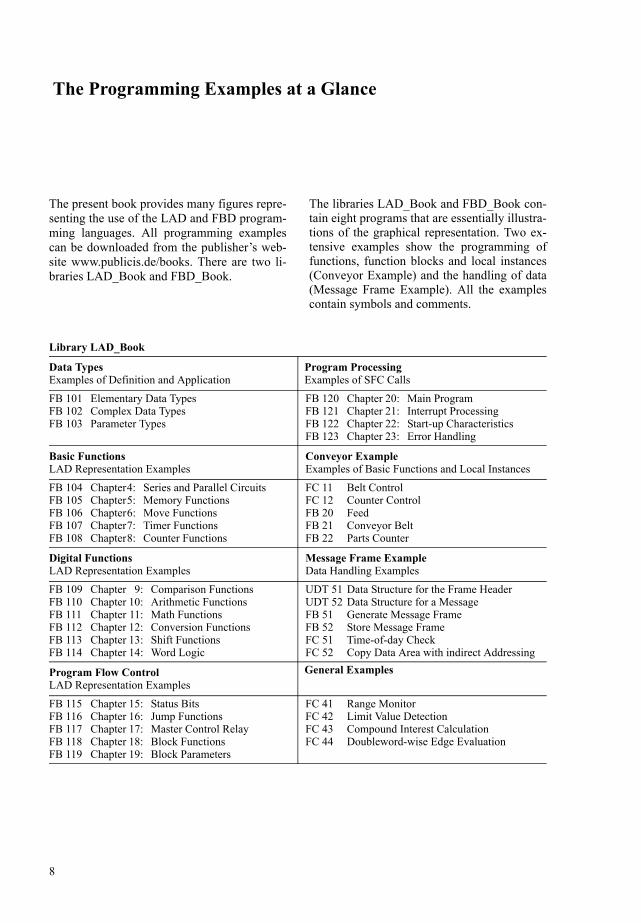

Automating with STEP 7
11
Contents
12
Contents
Introduction 19
1 SIMATIC S7-300400 Programmable Controller 20
11 Structure of the Programmable Controller 20
111 Components 20
112 S7-300 Station 20
113 S7-400 station 22
114 Fault-tolerant SIMATIC 23
115 Safety-related SIMATIC 24
116 CPU Memory Areas 25
12 Distributed IO 28
121 PROFIBUS DP 29
122 PROFINET IO 30
123 ActuatorSensor Interface 32
124 Gateways 33
13 Communications 35
131 Introduction 35
132 Subnets 37
133 Communications Services 40
134 Connections 42
14 Module Addresses 43
141 Signal Path 43
142 Slot Address 43
143 Logical Address 44
144 Module Start Address 44
145 Diagnostics Address 44
146 Addresses for Bus Nodes 45
15 Address Areas 45
151 User Data Area 45
152 Process Image 46
153 Consistent User Data 47
154 Bit Memories 48
2 STEP 7 Programming Software 49
21 STEP 7 Basis Package 49
211 Installation 49212 Automation License Manager 50213 SIMATIC Manager 50214 Projects and Libraries 53215 Multiprojects 54216 Online Help 54
22 Editing Projects 54
221 Creating Projects 54222 Managing Reorganizing and
Archiving 56223 Project Versions 57224 Creating and editing multiprojects 57
23 Configuring Stations 58
231 Arranging Modules 60232 Addressing Modules 60233 Parameterizing Modules 61234 Networking Modules with MPI 61235 Monitoring and Modifying
Modules 62
24 Configuring the Network 62
241 Configuring the Network View 64242 Configuring a Distributed IO
with the Network Configuration 64243 Configuring connections 65244 Gateways 68245 Loading the Connection Data 69246 Matching Projects in a
Multiproject 69
25 Creating the S7 Program 71
251 Introduction 71252 Symbol Table 71253 Program Editor 73254 Rewiring 77255 Address Priority 77256 Reference Data 78257 Language Setting 80
Contents
13
26 Online Mode 81
261 Connecting a PLC 81262 Protecting the User Program 82263 CPU Information 83264 Loading the User Program into
the CPU 83265 Block Handling 84
27 Testing the Program 86
271 Diagnosing the Hardware 87272 Determining the Cause of a STOP 87273 Monitoring and Modifying
Variables 87274 Forcing Variables 89275 Enabling Peripheral Outputs 90276 Test and process operation 91277 LADFBD Program Status 91278 Monitoring and Modifying
Data Addresses 92
3 SIMATIC S7 Program 94
31 Program Processing 94
311 Program Processing Methods 94312 Priority Classes 96313 Specifications for Program
Processing 96
32 Blocks 98
321 Block Types 98322 Block Structure 100323 Block Properties 100324 Block Interface 103
33 Programming Code Blocks 106
331 Opening Blocks 106332 Block Window 106333 Overview Window 107334 Programming Networks 108335 Addressing 109336 Editing LAD Elements 110337 Editing FBD Elements 111
34 Programming Data Blocks 113
341 Creating Data Blocks 113342 Types of Data Blocks 114343 Block Windows and Views 114
35 Variables Constants and Data Types 116
351 General Remarks Concerning Variables 116
352 Addressing Variables 117353 Overview of Data Types 119354 Elementary Data Types 120355 Complex Data Types 125356 Parameter Types 128357 User Data Types 128
Basic Functions 130
4 Binary Logic Operations 131
41 Series and Parallel Circuits (LAD) 131
411 NO Contact and NC Contact 131412 Series Circuits 132413 Parallel Circuits 132414 Combinations of Binary Logic
Operations 133415 Negating the Result of the Logic
Operation 134
42 Binary Logic Operations (FBD) 134
421 Elementary Binary Logic Operations 135
422 Combinations of Binary Logic Operations 138
423 Negating the Result of the Logic Operation 139
43 Taking Account of the Sensor Type 139
5 Memory Functions 142
51 LAD Coils 142
511 Single Coil 142512 Set and Reset Coil 142513 Memory Box 144
52 FBD Boxes 146
521 Assign 146522 Set and Reset Box 148523 Memory Box 148
53 Midline Outputs 150
531 Midline Outputs in LAD 150532 Midline Outputs in FBD 151
Contents
14
54 Edge Evaluation 152
541 How Edge Evaluation Works 152542 Edge Evaluation in LAD 152543 Edge Evaluation in FBD 153
55 Binary Scaler 154
551 Solution in LAD 154552 Solution in FBD 156
56 Example of a Conveyor Control System 156
6 Move Functions 161
61 General 161
62 MOVE Box 162
621 Processing the MOVE Box 162622 Moving Operands 163623 Moving Constants 164
63 System Functions for Data Transfer 165
631 ANY Pointer 165632 Copy Data Area 166633 Uninterruptible Copying of a
Data Area 166634 Fill Data Area 166635 Reading from Load Memory 168636 Writing into Load Memory 168
7 Timers 170
71 Programming a Timer 170
711 General Representation of a Timer 170
712 Starting a Timer 171713 Specifying the Duration of Time 172714 Resetting A Timer 173715 Checking a Timer 173716 Sequence of Timer Operations 174717 Timer Box in a Rung (LAD) 174718 Timer Box in a Logic Circuit
(FBD) 174
72 Pulse Timer 175
73 Extended Pulse Timer 176
74 On-Delay Timer 177
75 Retentive On-Delay Timer 178
76 Off-Delay Timer 179
77 IEC Timers 180
771 Pulse Timer SFB 3 TP 180772 On-Delay Timer SFB 4 TON 180773 Off-Delay Timer SFB 5 TOF 180
8 Counters 182
81 Programming a Counter 182
82 Setting and Resetting Counters 185
83 Counting 185
84 Checking a Counter 186
85 IEC Counters 186
851 Up Counter SFB 0 CTU 187852 Down Counter SFB 1 CTD 187853 Updown Counter SFB 2 CTUD 187
86 Parts Counter Example 188
Digital Functions 192
9 Comparison Functions 193
91 Processing a Comparison Function 193
92 Description of the Comparison Functions 195
10 Arithmetic Functions 197
101 Processing an Arithmetic Function 197
102 Calculating with Data Type INT 199
103 Calculating with Data Type DINT 200
104 Calculating with Data Type REAL 200
11 Mathematical Functions 202
111 Processing a Mathematical Function 202
112 Trigonometric Functions 204
113 Arc Functions 204
114 Miscellaneous Mathematical Functions 204
12 Conversion Functions 207
121 Processing a Conversion Function 207
Contents
15
122 Conversion of INT and DINT Numbers 209
123 Conversion of BCD Numbers 210
124 Conversion of REAL Numbers 210
125 Miscellaneous Conversion Functions 212
13 Shift Functions 213
131 Processing a Shift Function 213
132 Shift 215
133 Rotate 216
14 Word Logic 217
141 Processing a Word Logic Operation 217
142 Description of the Word Logic Operations 219
Program Flow Control 220
15 Status Bits 221
151 Description of the Status Bits 221
152 Setting the Status Bits 222
153 Evaluating the Status Bits 224
154 Using the Binary Result 225
1541 Setting the Binary Result BR 2251542 Main Rung ENENO Mechanism 2251543 ENO in the Case of User-written
Blocks 226
16 Jump Functions 227
161 Processing a Jump Function 227
162 Unconditional Jump 228
163 Jump if RLO = ldquo1rdquo 229
164 Jump if RLO = ldquo0rdquo 229
17 Master Control Relay 230
171 MCR Dependency 230
172 MCR Area 231
173 MCR Zone 232
174 Setting and Resetting lO Bits 233
18 Block Functions 235
181 Block Functions for Code Blocks 235
1811 Block Calls General 2361812 Call Box 2371813 CALL CoilBox 2381814 Block End Function 2391815 Temporary Local Data 2401816 Static Local Data 241
182 Block Functions for Data Blocks 244
1821 Two Data Block Registers 2441822 Accessing Data Operands 2451823 Opening a Data Block 2461824 Special Points in Data Addressing 247
183 System Functions for Data Blocks 248
1831 Creating a Data Block in Work Memory 249
1832 Creating a Data Block in Load Memory 250
1833 Deleting a Data Block 2511834 Testing a Data Block 251
19 Block Parameters 252
191 Block Parameters in General 252
1911 Defining the Block Parameters 2521912 Processing the Block Parameters 2531913 Declaration of the Block
Parameters 2531914 Declaration of the Function Value 2541915 Initializing Block Parameters 254
192 Formal Parameters 255
193 Actual Parameters 257
194 ldquoForwardingrdquo Block Parameters 260
195 Examples 260
1951 Conveyor Belt Example 2601952 Parts Counter Example 2611953 Feed Example 262
Program Processing 269
20 Main Program 270
201 Program Organization 270
2011 Program Structure 2702012 Program Organization 271
Contents
16
202 Scan Cycle Control 272
2021 Process Image Updating 2722022 Scan Cycle Monitoring Time 2742023 Minimum Scan Cycle Time
Background Scanning 2752024 Response Time 2762025 Start Information 276
203 Program Functions 278
2031 Time of day 2782032 Read System Clock 2802033 Run-Time Meter 2802034 Compressing CPU Memory 2822035 Waiting and Stopping 2822036 Multicomputing 2822037 Determining the OB Program
Runtime 2832038 Changing program protection 286
204 Communication via Distributed IO 287
2041 Addressing PROFIBUS DP 2872042 Configuring PROFIBUS DP 2912043 Special Functions for
PROFIBUS DP 3002044 Addressing PROFINET IO 3052045 Configuring PROFINET IO 3072046 Special Functions for
PROFINET IO 3142047 System blocks for distributed IO 323
205 Global Data Communication 331
2051 Fundamentals 3312052 Configuring GD communication 3332053 System Functions for
GD Communication 335
206 S7 Basic Communication 335
2061 Station-Internal S7 Basic Communication 335
2062 System Functions for Station-Internal S7 Basic Communication 336
2063 Station-External S7 Basic Communication 338
2064 System Functions for Station-External S7 Basic Communication 339
207 S7 Communication 341
2071 Fundamentals 3412072 Two-Way Data Exchange 3422073 One-Way Data Exchange 3442074 Transferring Print Data 3452075 Control Functions 3462076 Monitoring Functions 346
208 IE communication 350
2081 Basics 3502082 Establishing and clearing
down connections 3512083 Data transfer with TCP native
or ISO-on-TCP 3532084 Data transfer with UDP 355
209 PtP communication with S7-300C 357
2091 Fundamentals 3572092 ASCII driver and 3964(R)
procedure 3582093 RK512 computer coupling 359
2010 Configuration in RUN 362
20101 Preparation of Changes in Configuration 362
20102 Change Configuration 36420103 Load Configuration 36420104 CiR Synchronization Time 36520105 Effects on Program Execution 36520106 Control CiR Process 365
21 Interrupt Handling 367
211 General Remarks 367
212 Time-of-Day Interrupts 368
2121 Handling Time-of-Day Interrupts 3692122 Configuring Time-of-Day Interrupts
with STEP 7 3702123 System Functions for Time-of-Day
Interrupts 370
213 Time-Delay Interrupts 372
2131 Handling Time-Delay Interrupts 3722132 Configuring Time-Delay Interrupts
with STEP 7 3732133 System Functions for Time-Delay
Interrupts 373
Contents
17
214 Watchdog Interrupts 374
2141 Handling Watchdog Interrupts 3752142 Configuring Watchdog Interrupts
with STEP 7 376
215 Hardware Interrupts 376
2151 Generating a Hardware Interrupt 3762152 Servicing Hardware Interrupts 3772153 Configuring Hardware Interrupts
with STEP 7 378
216 DPV1 Interrupts 378
217 Multiprocessor Interrupt 380
218 Synchronous Cycle Interrupts 381
2181 Processing the Synchronous Cycle Interrupts 381
2182 Isochrone Updating Of Process Image 382
2183 Configuration of Synchronous Cycle Interrupts with STEP 7 383
219 Handling Interrupt Events 383
2191 Disabling and Enabling interrupts 3832192 Delaying and Enabling Interrupts 3842193 Reading additional Interrupt
Information 385
22 Start-up Characteristics 387
221 General Remarks 387
2211 Operating Modes 3872212 HOLD Mode 3882213 Disabling the Output Modules 3882214 Restart Organization Blocks 388
222 Power-Up 389
2221 STOP Mode 3892222 Memory Reset 3892223 Restoring the factory settings 3902224 Retentivity 3902225 Restart Parameterization 390
223 Types of Restart 391
2231 START-UP Mode 3912232 Cold Restart 3932233 Warm Restart 3932234 Hot Restart 394
224 Ascertaining a Module Address 394
225 Parameterizing Modules 397
2251 General remarks on parameterizing modules 397
2252 System Blocks for Module Parameterization 399
2253 Blocks for Transmitting Data Records 401
23 Error Handling 404
231 Synchronous Errors 404
232 Synchronous Error Handling 406
2321 Error Filters 4062322 Masking Synchronous Errors 4072323 Unmasking Synchronous Errors 4082324 Reading the Error Register 4082325 Entering a Substitute Value 408
233 Asynchronous Errors 408
234 System Diagnostics 411
2341 Diagnostic Events and Diagnostic Buffer 411
2342 Writing User Entries in theDiagnostic Buffer 411
2343 Evaluating Diagnostic Interrupts 4122344 Reading the System Status List 412
235 Web Server 415
2351 Activating the Web server 4152352 Reading out Web information 4152353 Web information 415
Appendix 417
24 Supplements to Graphic Programming 418
241 Block Protection 418
242 Indirect Addressing 419
2421 Pointers General Remarks 4192422 Area Pointer 4192423 DB Pointer 4192424 ANY Pointer 4212425 ldquoVariablerdquo ANY Pointer 421
243 Brief Description of the ldquoMessage Frame Examplerdquo 422
Contents
18
25 Block Libraries 426
251 Organization Blocks 426
252 System Function Blocks 427
253 IEC Function Blocks 430
254 S5-S7 Converting Blocks 431
255 TI-S7 Converting Blocks 432
256 PID Control Blocks 433
257 Communication Blocks 433
258 Miscellaneous Blocks 434
259 SIMATIC_NET_CP 434
2510 Redundant IO MGP V31 435
2511 Redundant IO CGP V40 435
2512 Redundant IO CGP V51 435
26 Function Set LAD 436
261 Basic Functions 436
262 Digital Functions 437
263 Program Flow Control 439
27 Function Set FBD 440
271 Basic Functions 440
272 Digital Functions 441
273 Program Flow Control 443
Index 444
Abbreviations 451
Introduction
19
Introduction
This portion of the book provides an overview of the SIMATIC S7-300400
The S7-300400 programmable controller is of modular design The modules with which it is configured can be central (in the vicinity of the CPU) or distributed without any special set-tings or parameter assignments having to be made In SIMATIC S7 systems distributed IO is an integral part of the system The CPU with its various memory areas forms the hardware basis for processing of the user programs A load memory contains the complete user pro-gram the parts of the program relevant to its execution at any given time are in a work mem-ory whose short access times are the prerequi-site for fast program processing
STEP 7 is the programming software for S7-300400 and the automation tool is the SIMATIC Manager The SIMATIC Manager is an application for the Windows operating sys-tems from Microsoft and contains all functions needed to set up a project When necessary the SIMATIC Manager starts additional tools for example to configure stations initialize mod-ules and to write and test programs
You formulate your automation solution in the STEP 7 programming languages The SIMATIC S7 program is structured that is to say it consists of blocks with defined functions that are composed of networks or rungs Differ-ent priority classes allow a graduated interrupt-ibility of the user program currently executing STEP 7 works with variables of various data types starting with binary variables (data type BOOL) through digital variables (eg data type INT or REAL for computing tasks) up to com-plex data types such as arrays or structures (combinations of variables of different types to form a single variable)
The first chapter contains an overview of the hardware in an S7-300400 programmable con-troller and the second chapter contains an over-view of the STEP 7 programming software The basis for the description is the function scope for STEP 7 Version 55
Chapter 3 ldquoSIMATIC S7 Programrdquo serves as an introduction to the most important elements of an S7 program and shows the programming of individual blocks in the programming lan-guages LAD and FBD The functions and oper-ations of LAD and FBD are then described in the subsequent chapters of the book All the descriptions are explained using brief exam-ples
1 SIMATIC S7-300400Programmable ControllerStructure of the programmable controller distributed IO communications module addresses operand areas
2 STEP 7 Programming SoftwareSIMATIC Manager processing a project configuring a station configuring a net-work writing programs (symbol table program editor) switching online testing programs
3 SIMATIC S7 ProgramProgram processing with priority classes program blocks addressing variables programming blocks with LAD and FBD variables and constants data types (over-view)
1 SIMATIC S7-300400 Programmable Controller
20
1 SIMATIC S7-300400 Programmable Controller
11 Structure of the Programmable Controller
111 Components
The SIMATIC S7-300400 is a modular pro-grammable controller comprising the following components
b RacksAccommodate the modules and connect them to each other
b Power supply (PS)Provides the internal supply voltages
b Central processing unit (CPU)Stores and processes the user program
b Interface modules (IMs)Connect the racks to one another
b Signal modules (SMs)Adapt the signals from the system to the internal signal level or control actuators via digital and analog signals
b Function modules (FMs)Execute complex or time-critical processes independently of the CPU
b Communications processors (CPs)Establish the connection to subsidiary net-works (subnets)
b SubnetsConnect programmable controllers to each other or to other devices
A programmable controller (or station) may consist of several racks which are linked to one another via bus cables The power supply CPU and IO modules (SMs FMs and CPs) are plugged into the central rack If there is not enough room in the central rack for the IO modules or if you want some or all IO modules to be separate from the central rack expansion racks are available which are connected to the central rack via interface modules (Figure 11)
It is also possible to connect distributed IO to a station (see Chapter 121 ldquoPROFIBUS DPrdquo)
The racks connect the modules with two buses the IO bus (or P bus) and the communication bus (or K bus) The IO bus is designed for high-speed exchange of input and output sig-nals the communication bus for the exchange of large amounts of data The communication bus connects the CPU and the programming device interface (MPI) with function modules and communications processors
112 S7-300 Station
Centralized configuration
In an S7-300 controller as many as 8 IO mod-ules can be plugged into the central rack Should this single-tier configuration prove insufficient you have two options for control-lers equipped with a CPU 313 or higher
b A two-tier configuration (with IM 365 up to 1 meter between racks) or
b A configuration of up to four tiers (with IM 360 and IM 361 up to 10 meters between racks)
You can operate a maximum of 8 modules in a rack The number of modules may be limited by the maximum permissible current per rack which is 12 A
The modules are linked to one another via a backplane bus which combines the functions of the P and K buses
Local bus segment
A special feature regarding configuration is the use of the FM 356 application module An FM 356 is able to ldquosplitrdquo a modules backplane bus and to take over control of the remaining mod-ules in the split-off ldquolocal bus segmentrdquo itself The limitations mentioned above regarding the
11 Structure of the Programmable Controller
21
Figure 11 Hardware Configuration for S7-300400
1 SIMATIC S7-300400 Programmable Controller
22
number of modules and the power consumption also apply in this case
Standard CPUs
The standard CPUs are available in versions that differ with regard to memory capacity and processing speed They range from the ldquosmall-estrdquo CPU 312 for lower-end applications with moderate processing speed requirements up to the CPU 319-3 PNDP with its large program memory and high processing performance for cross-sector automation tasks Equipped with the relevant interfaces some CPUs can be used for central control of the distributed IO via PROFIBUS and PROFINET A micro memory card (MMC) is required for operating the stan-dard CPUs ndash as with all innovated S7-300-CPUs This medium opens up new application possibilities compared to the previously used memory card (see Chapter 116 ldquoCPU Memory Areasrdquo)
The now discontinued CPU 318 can be re-placed by the CPUs 317 and 319
Compact CPUs
The 3xxC CPUs permit construction of com-pact mini programmable controllers Depend-ing on the version they already contain
b Integral IOsDigital and analog inputsoutputs
b Integral technology functionsCounting measurement control position-ing
b Integral communications interfacesPROFIBUS DP master or slave point-to-point coupling (PtP)
The technological functions are system blocks which use the onboard IO of the CPU
Technology CPUs
The CPUs 3xxT combine open-loop control functions with simple motion control functions The open-loop control component is designed as in a standard CPU It is configured parame-terized and programmed using STEP 7 The technology objects and the motion control com-ponent require the optional S7-Technology
package that is integrated in the SIMATIC Manager after installation
The Technology CPUs have a PROFIBUS DP interface that allows operation as DP master or DP slave The CPUs are used for cross-sector automation tasks in series mechanical equip-ment manufacture special mechanical equip-ment manufacture and plant building
Failsafe CPUs
The CPUs 3xxF are used in production plants with increased safety requirements The rele-vant PROFIBUS and PROFINET interfaces al-low the operation of safety-related distributed IO using the PROFIsafe bus profile (see ldquoSafety Integrated for the manufacturing industryrdquo un-der 115 ldquoSafety-related SIMATICrdquo) Standard modules for normal applications can be used parallel to safety-related operation
SIPLUS
The SIPLUS product family offers modules that can be used in harsh environments The SI-PLUS components are based on standard devic-es which have been specially converted for the respective application for example for an ex-tended temperature range increased resistance to vibration and shock or voltage ranges differ-ing from the standard Please therefore note the technical data for the respective SIPLUS mod-ule In order to carry out the configuration with STEP 7 use the equivalent type (the standard module on which it is based) this is specified for example on the modules nameplate
113 S7-400 station
Centralized configuration
The controller rack for the S7-400 is available in the UR1 (18 slots) UR2 (9 slots) and CR3 (4 slots) versions UR1 and UR2 can also be used as expansion racks The power supply and the CPU also occupy slots in the racks possibly even two or more per module If necessary the number of slots available can be increased using expansion racks UR1 and ER1 have 18 slots each UR2 and ER2 have 9 each
The IM 460-1 and IM 461-1 interface modules make it possible to have one expansion rack per
11 Structure of the Programmable Controller
23
interface up to 15 meters from the central rack including the 5 V supply voltage In addition as many as four expansion racks can be operated up to 5 meters away using IM 460-0 and IM 461-0 interface modules And finally IM 460-3 and IM 461-3 or IM 460-4 and 461-4 interface modules can be used to operate as many as four expansion racks at a distance of up to 100 or 600 meters away
A maximum of 21 expansion racks can be con-nected to a central rack To distinguish between racks you set the number of the rack on the coding switch of the receiving IM
The backplane bus consists of a parallel P bus and a serial K bus Expansion racks ER1 and ER2 are designed for ldquosimplerdquo signal modules which generate no hardware interrupts do not have to be supplied with 24 V voltage via the P bus require no back-up voltage and have no K bus connection The K bus is in racks UR1 UR2 and CR2 either when these racks are used as central racks or expansion racks with the numbers 1 to 6
Segmented rack
A special feature is the segmented rack CR2 The rack can accommodate two CPUs with a shared power supply while keeping them func-tionally separate The two CPUs can exchange data with one another via the K bus but have completely separate P buses for their own sig-nal modules
Multicomputing
In an S7-400 as many as 4 specially designed CPUs in a UR central rack can take part in mul-ticomputing Each module in this station is assigned to only one CPU both with its address and its interrupts For further details see Chap-ters 2036 ldquoMulticomputingrdquo and 217 ldquoMulti-processor Interruptrdquo
Connecting SIMATIC S5 modules
The IM 463-2 interface module allows you to connect S5 expansion units (EG 183U EG 185U EG 186U as well as ER 701-2 and ER 701-3) to an S7-400 and also allows central-ized expansion of the expansion units An IM 314 in the S5 expansion unit handles the link
You can operate all analog and digital modules allowed in these expansion units An S7-400 can accommodate as many as four IM 463-2 interface modules as many as four S5 expan-sion units can be connected in a distributed con-figuration to each of an IM 463-2s two inter-faces
114 Fault-tolerant SIMATIC
Two designs of SIMATIC S7 fault-tolerant automation systems are available for applica-tions with high fault tolerance demands for machines and processes software redundancy and S7-400HFH
Software redundancy
Using SIMATIC S7-300400 standard compo-nents you can establish a software-based redundant system with a master station control-ling the process and a standby station assuming control in the event of the master failing
Fault tolerance through software redundancy is suitable for slow processes because transfer to the standby station can require several seconds depending on the configuration of the program-mable controllers The process signals are ldquofro-zenrdquo during this time The standby station then continues operation with the data last valid in the master station
Redundancy of the inputoutput modules is implemented with distributed IO (ET 200M with IM 153-2 interface module for redundant PROFIBUS DP) The software redundancy can be configured with STEP 7 Version 52 and higher
Fault-tolerant SIMATIC S7-400H
The SIMATIC S7-400H is a fault-tolerant pro-grammable controller with redundant configu-ration comprising two central racks each with an H CPU and a synchronization module for data comparison via fiber optic cable Both controllers operate in ldquohot standbyrdquo mode in the event of a fault the intact controller assumes operation alone via automatic bump-less transfer The UR2-H mounting rack with two times nine slots makes it possible to estab-lish a fault-tolerant system in a single mounting rack
1 SIMATIC S7-300400 Programmable Controller
24
The IO can have normal availability (single-channel single-sided configuration) or enhanced availability (single-channel switched configuration withET 200M) Communication is carried out over a simple or a redundant bus
The user program is the same as that for a non-redundant controller the redundancy function is handled exclusively by the hardware and is invisible to the user The software package required for configuration is included in STEP 7 V53 and later The provided standard librar-ies Redundant IO contain blocks for supporting the redundant IO
115 Safety-related SIMATIC
Failsafe automation systems control processes in which the safe state can be achieved by direct switching off They are used in plants with increased safety requirements
The safety functions are located as appropriate in the safety-related user program of a corre-spondingly designed CPU and in the failsafe input and output modules An F-CPU complies with the safety requirements up to AK 6 in accor-dance with DIN V 19250DIN V VDE 0801 up to SIL 3 in accordance with IEC 61508 and up to Category 4 in accordance with EN 954-1 Safety functions can be executed parallel to a non-safety-related user program in the same CPU
Safety-related communication over PROFIBUS DP ndash also over PROFINET IO with S7 Distrib-uted Safety ndash uses the PROFIsafe bus profile This permits transmission of safety-related and non-safety-related data on a single bus cable
Safety Integrated for the manufacturing industry
S7 Distributed Safety is a failsafe automation system for the protection of machines and per-sonnel mainly for applications with machine controls and in the process industry
CPUs from the SIMATIC S7-300 S7-400 and ET 200S ranges are currently available as F-CPUs The safety-related IO modules are con-nected to S7-400 over PROFIBUS DP or PROFINET IO using the safety-related PROFIsafe bus profile With S7-300 and ET
200S use of safety-related IO modules is addi-tionally possible in the central rack
The hardware configuration and programming of the non-safety-related user program are car-ried out using the standard applications of STEP 7
The SIMATIC S7 Distributed Safety option package is required to program the safety-related parts of the program With this option package you can use the F-LAD or F-FBD pro-gramming languages to create the blocks which contain the safety-related program Interfacing to the IO is carried out using the process image as with the standard program S7 Distributed Safety also includes a library with TUumlV-certi-fied safety blocks There is an additional library available with F-blocks for press and burner controls
The safety-related user program can be exe-cuted parallel to the standard user program If an error is detected in the safety-related part of the program the CPU enters the STOP state
Safety Integrated for the process industry
S7 FFH Systems is a failsafe automation sys-tem based on S7-400 mainly for applications in the process industry The safety-related IO modules are connected over PROFIBUS DP using the safety-related PROFIsafe bus profile
An S7-400 F-CPU is provided with the safety-related control functions by application of an S7 F Systems Runtime license A non-safety-relat-ed user program can be executed parallel to the safety-related plant unit
In addition to fail-safety the S7-400FH also provides increased availability If a detected fault results in a STOP of the master CPU a re-action-free switch is made to the CPU running in hot standby mode The S7 H Systems option package is additionally required for operation as S7-400FH
The hardware configuration and programming of the non-safety-related user program are car-ried out using the standard applications of STEP 7
The S7 F Systems option package is addition-ally required for programming the safety-related program parts and additionally the
11 Structure of the Programmable Controller
25
CFC option package V50 SP3 and higher and the S7-SCL option package V50 and higher
The safety-related program is programmed using CFC (Continuous Function Chart) Pro-grammed safety-related function blocks from the supplied F-library can be called and inter-connected in this manner In addition to func-tions for programming safety functions they also contain functions for error detection and response In the event of faults and failures this guarantees that the failsafe system is held in a safe state or is transferred to a safe state If a fault is detected in the safety program the safety-related part of the plant is switched off whereas the remaining part can continue to operate
Failsafe IO
Failsafe signal modules (F-modules or F-submodules) are required for safety operation Failsafety is achieved with the integral safety functions and appropriate wiring of the sensors and actuators
The F-modules can also be used in standard applications with increased diagnostics require-ments The F-modules can be operated in redundant mode to increase the availability both in standard and safety operation with S7 FFH systems
The failsafe IO is available in various versions
b The failsafe signal modules of S7-300 design are used in the ET 200M distributed IO device or ndash with S7-Distributed Safety ndash also centrally
b Failsafe IO modules are available for the distributed IO devices in the designs ET 200S ET 200pro and ET 200eco
b For the ET 200S and ET 200pro distributed IO devices failsafe interface modules are also available as F-CPUs
b Failsafe DP standard slaves and ndash with S7-Distributed Safety also IO standard devices ndash can be used which can handle the PROFI-safe bus profile
Failsafe CPUs and signal modules are also available in SIPLUS design
116 CPU Memory Areas
Figure 12 shows the memory areas in the pro-gramming device the CPU and the signal mod-ules which are important for your program
The programming device contains the offline data These consist of the user program (pro-gram code and user data) the system data (eg hardware network and interconnection config-urations) and further project-specific data such as symbol tables and comments
The online data consist of the user program and the system data on the CPU and are accommo-dated in two areas namely load memory and work memory In addition the system memory is also present here
The IO modules contain memories for the sig-nal state of the inputs and outputs
The CPUs have a slot for a plug-in memory sub-module The load memory or parts thereof is located here (see ldquoPhysical design of CPU memoryrdquo further below) The memory sub-module is designed as a memory card (S7-400 CPUs) or as a micro memory card (S7-300 CPUs and ET200 CPUs derived from these) The firmware of the CPU operating system can also be updated using the memory submodule
Memory card
The memory module for the S7-400 CPUs is the memory card (MC) There are two types of memory card RAM cards and flash EPROM cards
If you want to expand load memory only use a RAM card A RAM card allows you to modify the entire user program online This is neces-sary for example when testing and starting up larger programs RAM memory cards lose their contents when unplugged
If you want to protect your user program includ-ing configuration data and module parametersagainst power failure following testing and starting up even without a backup battery use a flash EPROM card In this case load the entire program offline onto the flash EPROM card with the card plugged into the programming device With the relevant CPUs you can also load the program online with the memory card plugged into the CPU
1 SIMATIC S7-300400 Programmable Controller
26
Micro memory card
The memory submodule for the newer S7-300 CPUs is a micro memory card (MMC) The data on the MMC are saved non-volatile but can be read written and deleted as with a RAM This response permits data backup without a battery
The complete load memory is present on the MMC meaning that an MMC is always required for operation The MMC can be used as a portable memory medium for user pro-grams or firmware updates Using special sys-tem functions you can read or write data blocks on the MMC from the user program for exam-ple to read recipes from the MMC or to create a
measured-value archive on the MMC and to provide it with data
Load memory
The entire user program including configura-tion data (system data) is in the load memory The user program is always initially transferred from the programming device to the load mem-ory and from there to the work memory The program in the load memory is not processed as the control program
With a CPU 300 and a CPU ET 200 the load memory is present completely on the micro memory card Thus the contents of the load memory are retained even if the CPU is de-energized
Figure 12 CPU Memory Areas
11 Structure of the Programmable Controller
27
If the load memory with a CPU 400 consists of an integrated RAM or RAM memory card a backup battery is required in order to keep the user program retentive With an integrated EEPROM or a plug-in flash EPROM memory card as the load memory the CPU can be oper-ated without battery backup
From STEP 7 V51 onwards and with appro-priately designed CPUs you can save the com-plete project data as a compressed archive file in the load memory (see Chapter 222 ldquoManag-ing Reorganizing and Archivingrdquo)
Work memory
Work memory is designed in the form of high-speed RAM fully integrated in the CPU The operating system of the CPU copies the pro-gram code ldquorelevant to executionrdquo and the user data into the work memory ldquoRelevantrdquo is a characteristic of the existing objects and does not mean that a particular code block will nec-essarily be called and executed The ldquoactualrdquo control program is executed in the work mem-ory
Depending on the product the work memory can be designed either as a correlated area or divided according to program and data memo-ries where the latter can also be divided into retentive and non-retentive memories
When uploading the user program into the pro-gramming device the blocks are fetched from the load memory supplemented by the actual values of the data operands from the work mem-ory (further information can be found in Sections 264 ldquoLoading the User Program into the CPUrdquo and 265 ldquoBlock Handlingrdquo)
System memory
System memory contains the addresses (vari-ables) that you access in your program The addresses are combined into areas (address areas) containing a CPU-specific number of addresses Addresses may be for example inputs used to scan the signal states of momen-tary-contact switches and limit switches and outputs that you can use to control contactors and lamps
The system memory on a CPU contains the fol-lowing address areas
b Inputs (I)Inputs are an image (ldquoprocess imagerdquo) of the digital input modules
b Outputs (Q)Outputs are an image (ldquoprocess imagerdquo) of the digital output modules
b Bit memories (M) are information stores which are directly accessible from any point in the user pro-gram
b Timers (T)Timers are locations used to implement waiting and monitoring times
b Counters (Z)Counters are software-level locations which can be used for up and down counting
b Temporary local data (L)Locations used as dynamic intermediate buffers during block processing The tem-porary local data are located in the L stack which the CPU occupies dynamically dur-ing program execution
The letters enclosed in parentheses represent the abbreviations to be used for the different addresses when writing programs You may also assign a symbol to each variable and then use the symbol in place of the address identifier
The system memory also contains buffers for communication jobs and system messages (diagnostics buffer) The size of these data buff-ers as well as the size of the process image and the L stack are parameterizable on certain CPUs
Physical design of CPU memory
The physical design of the load memory is dif-ferent for the various types of CPU (Figure 13)
A CPU 300 or CPU ET 200 does not have an integrated load memory A micro memory card containing the load memory must always be in-serted to permit operation The load memory can be written and read like a RAM The phys-ical design means that the number of write op-erations is limited (no cyclic writing by user program) You can use the menu command COPY RAM TO ROM to transfer the current values of the data operands from the work memory to the load memory
1 SIMATIC S7-300400 Programmable Controller
28
With a CPU 300 with firmware version V2012 or later the work memory for the user data con-sists of a retentive part and a non-retentive part The control program is also present in the non-retentive part
The integrated RAM load memory in a CPU 400 is designed for small programs or for mod-ification of individual blocks if the load mem-ory is a flash EPROM memory card If the com-plete control program is larger than the inte-grated load memory you require a RAM mem-ory card for testing The tested program is then transmitted by the programming device to a flash EPROM memory card which you insert into the CPU for operation
The work memory of a CPU 400 is divided into two parts One part saves the program code the
other the user data The system and work mem-ories in a CPU 400 constitute one (physical) unit The system and work memories in the S7-400 CPUs constitute one (physical) unit If for example the size of the process image changes this has effects on the size of the work memory
12 Distributed IO
Distributed IO refers to modules connected via PROFIBUS DP or PROFINET IO PROFIBUS DP uses the PROFIBUS subnetwork for data transmission PROFINET IO the Industrial Ethernet subnetwork (for further information see Chapter 132 ldquoSubnetsrdquo)
Figure 13 Physical Design of CPU Memory
12 Distributed IO
29
121 PROFIBUS DP
PROFIBUS DP provides a standardized inter-face for transferring predominantly binary pro-cess data between an ldquointerface modulerdquo in the (central) programmable controller and the field devices This ldquointerface modulerdquo is called the DP master and the field devices are the DP slaves
The DP master and all the slaves it controls form a DP master system There can be up to 32 stations in one segment and up to 127 stations in the entire network A DP master can control a number of DP slaves specific to itself You can also connect programming devices to the PROFIBUS DP network as well as for exam-ple devices for operator control and monitor-ing ET 200 devices or SIMATIC S5 DP slaves
DP master system
PROFIBUS DP is usually operated as a ldquomono master systemrdquo that is one DP master controls several DP slaves The DP master is the only master on the bus with the exception of a tem-porarily available programming device (diag-nostics and service device) The DP master and the DP slaves assigned to it form a DP master system (Figure 14)
You can also install several DP master systems on one PROFIBUS subnet (multi master sys-
tem) However this increases the response time in individual cases because when a DP master has initialized ldquoitsrdquo DP slaves the access rights fall to the next DP master that in turn initializes ldquoitsrdquo DP slaves etc
You can reduce the response time if a DP mas-ter system contains only a few DP slaves Since it is possible to operate several DP masters in one S7 station you can distribute the DP slaves of a station over several DP master systems In multicomputing every CPU has its own DP master systems
DP master
The DP master is the active node on the PRO-FIBUS network It exchanges cyclic data with ldquoitsrdquo DP slaves A DP master can be
b A CPU with integral DP master interface or plug-in interface submodule (eg CPU 315-2DP CPU 417)
b An interface module in conjunction with a CPU (eg IM 467)
b A CP in conjunction with a CPU (eg CP 342-5 CP 443-5)
There are ldquoClass 1 mastersrdquo for data exchange in process operation and ldquoClass 2 mastersrdquo for service and diagnostics (eg a programming device)
Figure 14 Components of a PROFIBUS DP Master System in an RS485 Segment

Contents
14
54 Edge Evaluation 152
541 How Edge Evaluation Works 152542 Edge Evaluation in LAD 152543 Edge Evaluation in FBD 153
55 Binary Scaler 154
551 Solution in LAD 154552 Solution in FBD 156
56 Example of a Conveyor Control System 156
6 Move Functions 161
61 General 161
62 MOVE Box 162
621 Processing the MOVE Box 162622 Moving Operands 163623 Moving Constants 164
63 System Functions for Data Transfer 165
631 ANY Pointer 165632 Copy Data Area 166633 Uninterruptible Copying of a
Data Area 166634 Fill Data Area 166635 Reading from Load Memory 168636 Writing into Load Memory 168
7 Timers 170
71 Programming a Timer 170
711 General Representation of a Timer 170
712 Starting a Timer 171713 Specifying the Duration of Time 172714 Resetting A Timer 173715 Checking a Timer 173716 Sequence of Timer Operations 174717 Timer Box in a Rung (LAD) 174718 Timer Box in a Logic Circuit
(FBD) 174
72 Pulse Timer 175
73 Extended Pulse Timer 176
74 On-Delay Timer 177
75 Retentive On-Delay Timer 178
76 Off-Delay Timer 179
77 IEC Timers 180
771 Pulse Timer SFB 3 TP 180772 On-Delay Timer SFB 4 TON 180773 Off-Delay Timer SFB 5 TOF 180
8 Counters 182
81 Programming a Counter 182
82 Setting and Resetting Counters 185
83 Counting 185
84 Checking a Counter 186
85 IEC Counters 186
851 Up Counter SFB 0 CTU 187852 Down Counter SFB 1 CTD 187853 Updown Counter SFB 2 CTUD 187
86 Parts Counter Example 188
Digital Functions 192
9 Comparison Functions 193
91 Processing a Comparison Function 193
92 Description of the Comparison Functions 195
10 Arithmetic Functions 197
101 Processing an Arithmetic Function 197
102 Calculating with Data Type INT 199
103 Calculating with Data Type DINT 200
104 Calculating with Data Type REAL 200
11 Mathematical Functions 202
111 Processing a Mathematical Function 202
112 Trigonometric Functions 204
113 Arc Functions 204
114 Miscellaneous Mathematical Functions 204
12 Conversion Functions 207
121 Processing a Conversion Function 207
Contents
15
122 Conversion of INT and DINT Numbers 209
123 Conversion of BCD Numbers 210
124 Conversion of REAL Numbers 210
125 Miscellaneous Conversion Functions 212
13 Shift Functions 213
131 Processing a Shift Function 213
132 Shift 215
133 Rotate 216
14 Word Logic 217
141 Processing a Word Logic Operation 217
142 Description of the Word Logic Operations 219
Program Flow Control 220
15 Status Bits 221
151 Description of the Status Bits 221
152 Setting the Status Bits 222
153 Evaluating the Status Bits 224
154 Using the Binary Result 225
1541 Setting the Binary Result BR 2251542 Main Rung ENENO Mechanism 2251543 ENO in the Case of User-written
Blocks 226
16 Jump Functions 227
161 Processing a Jump Function 227
162 Unconditional Jump 228
163 Jump if RLO = ldquo1rdquo 229
164 Jump if RLO = ldquo0rdquo 229
17 Master Control Relay 230
171 MCR Dependency 230
172 MCR Area 231
173 MCR Zone 232
174 Setting and Resetting lO Bits 233
18 Block Functions 235
181 Block Functions for Code Blocks 235
1811 Block Calls General 2361812 Call Box 2371813 CALL CoilBox 2381814 Block End Function 2391815 Temporary Local Data 2401816 Static Local Data 241
182 Block Functions for Data Blocks 244
1821 Two Data Block Registers 2441822 Accessing Data Operands 2451823 Opening a Data Block 2461824 Special Points in Data Addressing 247
183 System Functions for Data Blocks 248
1831 Creating a Data Block in Work Memory 249
1832 Creating a Data Block in Load Memory 250
1833 Deleting a Data Block 2511834 Testing a Data Block 251
19 Block Parameters 252
191 Block Parameters in General 252
1911 Defining the Block Parameters 2521912 Processing the Block Parameters 2531913 Declaration of the Block
Parameters 2531914 Declaration of the Function Value 2541915 Initializing Block Parameters 254
192 Formal Parameters 255
193 Actual Parameters 257
194 ldquoForwardingrdquo Block Parameters 260
195 Examples 260
1951 Conveyor Belt Example 2601952 Parts Counter Example 2611953 Feed Example 262
Program Processing 269
20 Main Program 270
201 Program Organization 270
2011 Program Structure 2702012 Program Organization 271
Contents
16
202 Scan Cycle Control 272
2021 Process Image Updating 2722022 Scan Cycle Monitoring Time 2742023 Minimum Scan Cycle Time
Background Scanning 2752024 Response Time 2762025 Start Information 276
203 Program Functions 278
2031 Time of day 2782032 Read System Clock 2802033 Run-Time Meter 2802034 Compressing CPU Memory 2822035 Waiting and Stopping 2822036 Multicomputing 2822037 Determining the OB Program
Runtime 2832038 Changing program protection 286
204 Communication via Distributed IO 287
2041 Addressing PROFIBUS DP 2872042 Configuring PROFIBUS DP 2912043 Special Functions for
PROFIBUS DP 3002044 Addressing PROFINET IO 3052045 Configuring PROFINET IO 3072046 Special Functions for
PROFINET IO 3142047 System blocks for distributed IO 323
205 Global Data Communication 331
2051 Fundamentals 3312052 Configuring GD communication 3332053 System Functions for
GD Communication 335
206 S7 Basic Communication 335
2061 Station-Internal S7 Basic Communication 335
2062 System Functions for Station-Internal S7 Basic Communication 336
2063 Station-External S7 Basic Communication 338
2064 System Functions for Station-External S7 Basic Communication 339
207 S7 Communication 341
2071 Fundamentals 3412072 Two-Way Data Exchange 3422073 One-Way Data Exchange 3442074 Transferring Print Data 3452075 Control Functions 3462076 Monitoring Functions 346
208 IE communication 350
2081 Basics 3502082 Establishing and clearing
down connections 3512083 Data transfer with TCP native
or ISO-on-TCP 3532084 Data transfer with UDP 355
209 PtP communication with S7-300C 357
2091 Fundamentals 3572092 ASCII driver and 3964(R)
procedure 3582093 RK512 computer coupling 359
2010 Configuration in RUN 362
20101 Preparation of Changes in Configuration 362
20102 Change Configuration 36420103 Load Configuration 36420104 CiR Synchronization Time 36520105 Effects on Program Execution 36520106 Control CiR Process 365
21 Interrupt Handling 367
211 General Remarks 367
212 Time-of-Day Interrupts 368
2121 Handling Time-of-Day Interrupts 3692122 Configuring Time-of-Day Interrupts
with STEP 7 3702123 System Functions for Time-of-Day
Interrupts 370
213 Time-Delay Interrupts 372
2131 Handling Time-Delay Interrupts 3722132 Configuring Time-Delay Interrupts
with STEP 7 3732133 System Functions for Time-Delay
Interrupts 373
Contents
17
214 Watchdog Interrupts 374
2141 Handling Watchdog Interrupts 3752142 Configuring Watchdog Interrupts
with STEP 7 376
215 Hardware Interrupts 376
2151 Generating a Hardware Interrupt 3762152 Servicing Hardware Interrupts 3772153 Configuring Hardware Interrupts
with STEP 7 378
216 DPV1 Interrupts 378
217 Multiprocessor Interrupt 380
218 Synchronous Cycle Interrupts 381
2181 Processing the Synchronous Cycle Interrupts 381
2182 Isochrone Updating Of Process Image 382
2183 Configuration of Synchronous Cycle Interrupts with STEP 7 383
219 Handling Interrupt Events 383
2191 Disabling and Enabling interrupts 3832192 Delaying and Enabling Interrupts 3842193 Reading additional Interrupt
Information 385
22 Start-up Characteristics 387
221 General Remarks 387
2211 Operating Modes 3872212 HOLD Mode 3882213 Disabling the Output Modules 3882214 Restart Organization Blocks 388
222 Power-Up 389
2221 STOP Mode 3892222 Memory Reset 3892223 Restoring the factory settings 3902224 Retentivity 3902225 Restart Parameterization 390
223 Types of Restart 391
2231 START-UP Mode 3912232 Cold Restart 3932233 Warm Restart 3932234 Hot Restart 394
224 Ascertaining a Module Address 394
225 Parameterizing Modules 397
2251 General remarks on parameterizing modules 397
2252 System Blocks for Module Parameterization 399
2253 Blocks for Transmitting Data Records 401
23 Error Handling 404
231 Synchronous Errors 404
232 Synchronous Error Handling 406
2321 Error Filters 4062322 Masking Synchronous Errors 4072323 Unmasking Synchronous Errors 4082324 Reading the Error Register 4082325 Entering a Substitute Value 408
233 Asynchronous Errors 408
234 System Diagnostics 411
2341 Diagnostic Events and Diagnostic Buffer 411
2342 Writing User Entries in theDiagnostic Buffer 411
2343 Evaluating Diagnostic Interrupts 4122344 Reading the System Status List 412
235 Web Server 415
2351 Activating the Web server 4152352 Reading out Web information 4152353 Web information 415
Appendix 417
24 Supplements to Graphic Programming 418
241 Block Protection 418
242 Indirect Addressing 419
2421 Pointers General Remarks 4192422 Area Pointer 4192423 DB Pointer 4192424 ANY Pointer 4212425 ldquoVariablerdquo ANY Pointer 421
243 Brief Description of the ldquoMessage Frame Examplerdquo 422
Contents
18
25 Block Libraries 426
251 Organization Blocks 426
252 System Function Blocks 427
253 IEC Function Blocks 430
254 S5-S7 Converting Blocks 431
255 TI-S7 Converting Blocks 432
256 PID Control Blocks 433
257 Communication Blocks 433
258 Miscellaneous Blocks 434
259 SIMATIC_NET_CP 434
2510 Redundant IO MGP V31 435
2511 Redundant IO CGP V40 435
2512 Redundant IO CGP V51 435
26 Function Set LAD 436
261 Basic Functions 436
262 Digital Functions 437
263 Program Flow Control 439
27 Function Set FBD 440
271 Basic Functions 440
272 Digital Functions 441
273 Program Flow Control 443
Index 444
Abbreviations 451
Introduction
19
Introduction
This portion of the book provides an overview of the SIMATIC S7-300400
The S7-300400 programmable controller is of modular design The modules with which it is configured can be central (in the vicinity of the CPU) or distributed without any special set-tings or parameter assignments having to be made In SIMATIC S7 systems distributed IO is an integral part of the system The CPU with its various memory areas forms the hardware basis for processing of the user programs A load memory contains the complete user pro-gram the parts of the program relevant to its execution at any given time are in a work mem-ory whose short access times are the prerequi-site for fast program processing
STEP 7 is the programming software for S7-300400 and the automation tool is the SIMATIC Manager The SIMATIC Manager is an application for the Windows operating sys-tems from Microsoft and contains all functions needed to set up a project When necessary the SIMATIC Manager starts additional tools for example to configure stations initialize mod-ules and to write and test programs
You formulate your automation solution in the STEP 7 programming languages The SIMATIC S7 program is structured that is to say it consists of blocks with defined functions that are composed of networks or rungs Differ-ent priority classes allow a graduated interrupt-ibility of the user program currently executing STEP 7 works with variables of various data types starting with binary variables (data type BOOL) through digital variables (eg data type INT or REAL for computing tasks) up to com-plex data types such as arrays or structures (combinations of variables of different types to form a single variable)
The first chapter contains an overview of the hardware in an S7-300400 programmable con-troller and the second chapter contains an over-view of the STEP 7 programming software The basis for the description is the function scope for STEP 7 Version 55
Chapter 3 ldquoSIMATIC S7 Programrdquo serves as an introduction to the most important elements of an S7 program and shows the programming of individual blocks in the programming lan-guages LAD and FBD The functions and oper-ations of LAD and FBD are then described in the subsequent chapters of the book All the descriptions are explained using brief exam-ples
1 SIMATIC S7-300400Programmable ControllerStructure of the programmable controller distributed IO communications module addresses operand areas
2 STEP 7 Programming SoftwareSIMATIC Manager processing a project configuring a station configuring a net-work writing programs (symbol table program editor) switching online testing programs
3 SIMATIC S7 ProgramProgram processing with priority classes program blocks addressing variables programming blocks with LAD and FBD variables and constants data types (over-view)
1 SIMATIC S7-300400 Programmable Controller
20
1 SIMATIC S7-300400 Programmable Controller
11 Structure of the Programmable Controller
111 Components
The SIMATIC S7-300400 is a modular pro-grammable controller comprising the following components
b RacksAccommodate the modules and connect them to each other
b Power supply (PS)Provides the internal supply voltages
b Central processing unit (CPU)Stores and processes the user program
b Interface modules (IMs)Connect the racks to one another
b Signal modules (SMs)Adapt the signals from the system to the internal signal level or control actuators via digital and analog signals
b Function modules (FMs)Execute complex or time-critical processes independently of the CPU
b Communications processors (CPs)Establish the connection to subsidiary net-works (subnets)
b SubnetsConnect programmable controllers to each other or to other devices
A programmable controller (or station) may consist of several racks which are linked to one another via bus cables The power supply CPU and IO modules (SMs FMs and CPs) are plugged into the central rack If there is not enough room in the central rack for the IO modules or if you want some or all IO modules to be separate from the central rack expansion racks are available which are connected to the central rack via interface modules (Figure 11)
It is also possible to connect distributed IO to a station (see Chapter 121 ldquoPROFIBUS DPrdquo)
The racks connect the modules with two buses the IO bus (or P bus) and the communication bus (or K bus) The IO bus is designed for high-speed exchange of input and output sig-nals the communication bus for the exchange of large amounts of data The communication bus connects the CPU and the programming device interface (MPI) with function modules and communications processors
112 S7-300 Station
Centralized configuration
In an S7-300 controller as many as 8 IO mod-ules can be plugged into the central rack Should this single-tier configuration prove insufficient you have two options for control-lers equipped with a CPU 313 or higher
b A two-tier configuration (with IM 365 up to 1 meter between racks) or
b A configuration of up to four tiers (with IM 360 and IM 361 up to 10 meters between racks)
You can operate a maximum of 8 modules in a rack The number of modules may be limited by the maximum permissible current per rack which is 12 A
The modules are linked to one another via a backplane bus which combines the functions of the P and K buses
Local bus segment
A special feature regarding configuration is the use of the FM 356 application module An FM 356 is able to ldquosplitrdquo a modules backplane bus and to take over control of the remaining mod-ules in the split-off ldquolocal bus segmentrdquo itself The limitations mentioned above regarding the
11 Structure of the Programmable Controller
21
Figure 11 Hardware Configuration for S7-300400
1 SIMATIC S7-300400 Programmable Controller
22
number of modules and the power consumption also apply in this case
Standard CPUs
The standard CPUs are available in versions that differ with regard to memory capacity and processing speed They range from the ldquosmall-estrdquo CPU 312 for lower-end applications with moderate processing speed requirements up to the CPU 319-3 PNDP with its large program memory and high processing performance for cross-sector automation tasks Equipped with the relevant interfaces some CPUs can be used for central control of the distributed IO via PROFIBUS and PROFINET A micro memory card (MMC) is required for operating the stan-dard CPUs ndash as with all innovated S7-300-CPUs This medium opens up new application possibilities compared to the previously used memory card (see Chapter 116 ldquoCPU Memory Areasrdquo)
The now discontinued CPU 318 can be re-placed by the CPUs 317 and 319
Compact CPUs
The 3xxC CPUs permit construction of com-pact mini programmable controllers Depend-ing on the version they already contain
b Integral IOsDigital and analog inputsoutputs
b Integral technology functionsCounting measurement control position-ing
b Integral communications interfacesPROFIBUS DP master or slave point-to-point coupling (PtP)
The technological functions are system blocks which use the onboard IO of the CPU
Technology CPUs
The CPUs 3xxT combine open-loop control functions with simple motion control functions The open-loop control component is designed as in a standard CPU It is configured parame-terized and programmed using STEP 7 The technology objects and the motion control com-ponent require the optional S7-Technology
package that is integrated in the SIMATIC Manager after installation
The Technology CPUs have a PROFIBUS DP interface that allows operation as DP master or DP slave The CPUs are used for cross-sector automation tasks in series mechanical equip-ment manufacture special mechanical equip-ment manufacture and plant building
Failsafe CPUs
The CPUs 3xxF are used in production plants with increased safety requirements The rele-vant PROFIBUS and PROFINET interfaces al-low the operation of safety-related distributed IO using the PROFIsafe bus profile (see ldquoSafety Integrated for the manufacturing industryrdquo un-der 115 ldquoSafety-related SIMATICrdquo) Standard modules for normal applications can be used parallel to safety-related operation
SIPLUS
The SIPLUS product family offers modules that can be used in harsh environments The SI-PLUS components are based on standard devic-es which have been specially converted for the respective application for example for an ex-tended temperature range increased resistance to vibration and shock or voltage ranges differ-ing from the standard Please therefore note the technical data for the respective SIPLUS mod-ule In order to carry out the configuration with STEP 7 use the equivalent type (the standard module on which it is based) this is specified for example on the modules nameplate
113 S7-400 station
Centralized configuration
The controller rack for the S7-400 is available in the UR1 (18 slots) UR2 (9 slots) and CR3 (4 slots) versions UR1 and UR2 can also be used as expansion racks The power supply and the CPU also occupy slots in the racks possibly even two or more per module If necessary the number of slots available can be increased using expansion racks UR1 and ER1 have 18 slots each UR2 and ER2 have 9 each
The IM 460-1 and IM 461-1 interface modules make it possible to have one expansion rack per
11 Structure of the Programmable Controller
23
interface up to 15 meters from the central rack including the 5 V supply voltage In addition as many as four expansion racks can be operated up to 5 meters away using IM 460-0 and IM 461-0 interface modules And finally IM 460-3 and IM 461-3 or IM 460-4 and 461-4 interface modules can be used to operate as many as four expansion racks at a distance of up to 100 or 600 meters away
A maximum of 21 expansion racks can be con-nected to a central rack To distinguish between racks you set the number of the rack on the coding switch of the receiving IM
The backplane bus consists of a parallel P bus and a serial K bus Expansion racks ER1 and ER2 are designed for ldquosimplerdquo signal modules which generate no hardware interrupts do not have to be supplied with 24 V voltage via the P bus require no back-up voltage and have no K bus connection The K bus is in racks UR1 UR2 and CR2 either when these racks are used as central racks or expansion racks with the numbers 1 to 6
Segmented rack
A special feature is the segmented rack CR2 The rack can accommodate two CPUs with a shared power supply while keeping them func-tionally separate The two CPUs can exchange data with one another via the K bus but have completely separate P buses for their own sig-nal modules
Multicomputing
In an S7-400 as many as 4 specially designed CPUs in a UR central rack can take part in mul-ticomputing Each module in this station is assigned to only one CPU both with its address and its interrupts For further details see Chap-ters 2036 ldquoMulticomputingrdquo and 217 ldquoMulti-processor Interruptrdquo
Connecting SIMATIC S5 modules
The IM 463-2 interface module allows you to connect S5 expansion units (EG 183U EG 185U EG 186U as well as ER 701-2 and ER 701-3) to an S7-400 and also allows central-ized expansion of the expansion units An IM 314 in the S5 expansion unit handles the link
You can operate all analog and digital modules allowed in these expansion units An S7-400 can accommodate as many as four IM 463-2 interface modules as many as four S5 expan-sion units can be connected in a distributed con-figuration to each of an IM 463-2s two inter-faces
114 Fault-tolerant SIMATIC
Two designs of SIMATIC S7 fault-tolerant automation systems are available for applica-tions with high fault tolerance demands for machines and processes software redundancy and S7-400HFH
Software redundancy
Using SIMATIC S7-300400 standard compo-nents you can establish a software-based redundant system with a master station control-ling the process and a standby station assuming control in the event of the master failing
Fault tolerance through software redundancy is suitable for slow processes because transfer to the standby station can require several seconds depending on the configuration of the program-mable controllers The process signals are ldquofro-zenrdquo during this time The standby station then continues operation with the data last valid in the master station
Redundancy of the inputoutput modules is implemented with distributed IO (ET 200M with IM 153-2 interface module for redundant PROFIBUS DP) The software redundancy can be configured with STEP 7 Version 52 and higher
Fault-tolerant SIMATIC S7-400H
The SIMATIC S7-400H is a fault-tolerant pro-grammable controller with redundant configu-ration comprising two central racks each with an H CPU and a synchronization module for data comparison via fiber optic cable Both controllers operate in ldquohot standbyrdquo mode in the event of a fault the intact controller assumes operation alone via automatic bump-less transfer The UR2-H mounting rack with two times nine slots makes it possible to estab-lish a fault-tolerant system in a single mounting rack
1 SIMATIC S7-300400 Programmable Controller
24
The IO can have normal availability (single-channel single-sided configuration) or enhanced availability (single-channel switched configuration withET 200M) Communication is carried out over a simple or a redundant bus
The user program is the same as that for a non-redundant controller the redundancy function is handled exclusively by the hardware and is invisible to the user The software package required for configuration is included in STEP 7 V53 and later The provided standard librar-ies Redundant IO contain blocks for supporting the redundant IO
115 Safety-related SIMATIC
Failsafe automation systems control processes in which the safe state can be achieved by direct switching off They are used in plants with increased safety requirements
The safety functions are located as appropriate in the safety-related user program of a corre-spondingly designed CPU and in the failsafe input and output modules An F-CPU complies with the safety requirements up to AK 6 in accor-dance with DIN V 19250DIN V VDE 0801 up to SIL 3 in accordance with IEC 61508 and up to Category 4 in accordance with EN 954-1 Safety functions can be executed parallel to a non-safety-related user program in the same CPU
Safety-related communication over PROFIBUS DP ndash also over PROFINET IO with S7 Distrib-uted Safety ndash uses the PROFIsafe bus profile This permits transmission of safety-related and non-safety-related data on a single bus cable
Safety Integrated for the manufacturing industry
S7 Distributed Safety is a failsafe automation system for the protection of machines and per-sonnel mainly for applications with machine controls and in the process industry
CPUs from the SIMATIC S7-300 S7-400 and ET 200S ranges are currently available as F-CPUs The safety-related IO modules are con-nected to S7-400 over PROFIBUS DP or PROFINET IO using the safety-related PROFIsafe bus profile With S7-300 and ET
200S use of safety-related IO modules is addi-tionally possible in the central rack
The hardware configuration and programming of the non-safety-related user program are car-ried out using the standard applications of STEP 7
The SIMATIC S7 Distributed Safety option package is required to program the safety-related parts of the program With this option package you can use the F-LAD or F-FBD pro-gramming languages to create the blocks which contain the safety-related program Interfacing to the IO is carried out using the process image as with the standard program S7 Distributed Safety also includes a library with TUumlV-certi-fied safety blocks There is an additional library available with F-blocks for press and burner controls
The safety-related user program can be exe-cuted parallel to the standard user program If an error is detected in the safety-related part of the program the CPU enters the STOP state
Safety Integrated for the process industry
S7 FFH Systems is a failsafe automation sys-tem based on S7-400 mainly for applications in the process industry The safety-related IO modules are connected over PROFIBUS DP using the safety-related PROFIsafe bus profile
An S7-400 F-CPU is provided with the safety-related control functions by application of an S7 F Systems Runtime license A non-safety-relat-ed user program can be executed parallel to the safety-related plant unit
In addition to fail-safety the S7-400FH also provides increased availability If a detected fault results in a STOP of the master CPU a re-action-free switch is made to the CPU running in hot standby mode The S7 H Systems option package is additionally required for operation as S7-400FH
The hardware configuration and programming of the non-safety-related user program are car-ried out using the standard applications of STEP 7
The S7 F Systems option package is addition-ally required for programming the safety-related program parts and additionally the
11 Structure of the Programmable Controller
25
CFC option package V50 SP3 and higher and the S7-SCL option package V50 and higher
The safety-related program is programmed using CFC (Continuous Function Chart) Pro-grammed safety-related function blocks from the supplied F-library can be called and inter-connected in this manner In addition to func-tions for programming safety functions they also contain functions for error detection and response In the event of faults and failures this guarantees that the failsafe system is held in a safe state or is transferred to a safe state If a fault is detected in the safety program the safety-related part of the plant is switched off whereas the remaining part can continue to operate
Failsafe IO
Failsafe signal modules (F-modules or F-submodules) are required for safety operation Failsafety is achieved with the integral safety functions and appropriate wiring of the sensors and actuators
The F-modules can also be used in standard applications with increased diagnostics require-ments The F-modules can be operated in redundant mode to increase the availability both in standard and safety operation with S7 FFH systems
The failsafe IO is available in various versions
b The failsafe signal modules of S7-300 design are used in the ET 200M distributed IO device or ndash with S7-Distributed Safety ndash also centrally
b Failsafe IO modules are available for the distributed IO devices in the designs ET 200S ET 200pro and ET 200eco
b For the ET 200S and ET 200pro distributed IO devices failsafe interface modules are also available as F-CPUs
b Failsafe DP standard slaves and ndash with S7-Distributed Safety also IO standard devices ndash can be used which can handle the PROFI-safe bus profile
Failsafe CPUs and signal modules are also available in SIPLUS design
116 CPU Memory Areas
Figure 12 shows the memory areas in the pro-gramming device the CPU and the signal mod-ules which are important for your program
The programming device contains the offline data These consist of the user program (pro-gram code and user data) the system data (eg hardware network and interconnection config-urations) and further project-specific data such as symbol tables and comments
The online data consist of the user program and the system data on the CPU and are accommo-dated in two areas namely load memory and work memory In addition the system memory is also present here
The IO modules contain memories for the sig-nal state of the inputs and outputs
The CPUs have a slot for a plug-in memory sub-module The load memory or parts thereof is located here (see ldquoPhysical design of CPU memoryrdquo further below) The memory sub-module is designed as a memory card (S7-400 CPUs) or as a micro memory card (S7-300 CPUs and ET200 CPUs derived from these) The firmware of the CPU operating system can also be updated using the memory submodule
Memory card
The memory module for the S7-400 CPUs is the memory card (MC) There are two types of memory card RAM cards and flash EPROM cards
If you want to expand load memory only use a RAM card A RAM card allows you to modify the entire user program online This is neces-sary for example when testing and starting up larger programs RAM memory cards lose their contents when unplugged
If you want to protect your user program includ-ing configuration data and module parametersagainst power failure following testing and starting up even without a backup battery use a flash EPROM card In this case load the entire program offline onto the flash EPROM card with the card plugged into the programming device With the relevant CPUs you can also load the program online with the memory card plugged into the CPU
1 SIMATIC S7-300400 Programmable Controller
26
Micro memory card
The memory submodule for the newer S7-300 CPUs is a micro memory card (MMC) The data on the MMC are saved non-volatile but can be read written and deleted as with a RAM This response permits data backup without a battery
The complete load memory is present on the MMC meaning that an MMC is always required for operation The MMC can be used as a portable memory medium for user pro-grams or firmware updates Using special sys-tem functions you can read or write data blocks on the MMC from the user program for exam-ple to read recipes from the MMC or to create a
measured-value archive on the MMC and to provide it with data
Load memory
The entire user program including configura-tion data (system data) is in the load memory The user program is always initially transferred from the programming device to the load mem-ory and from there to the work memory The program in the load memory is not processed as the control program
With a CPU 300 and a CPU ET 200 the load memory is present completely on the micro memory card Thus the contents of the load memory are retained even if the CPU is de-energized
Figure 12 CPU Memory Areas
11 Structure of the Programmable Controller
27
If the load memory with a CPU 400 consists of an integrated RAM or RAM memory card a backup battery is required in order to keep the user program retentive With an integrated EEPROM or a plug-in flash EPROM memory card as the load memory the CPU can be oper-ated without battery backup
From STEP 7 V51 onwards and with appro-priately designed CPUs you can save the com-plete project data as a compressed archive file in the load memory (see Chapter 222 ldquoManag-ing Reorganizing and Archivingrdquo)
Work memory
Work memory is designed in the form of high-speed RAM fully integrated in the CPU The operating system of the CPU copies the pro-gram code ldquorelevant to executionrdquo and the user data into the work memory ldquoRelevantrdquo is a characteristic of the existing objects and does not mean that a particular code block will nec-essarily be called and executed The ldquoactualrdquo control program is executed in the work mem-ory
Depending on the product the work memory can be designed either as a correlated area or divided according to program and data memo-ries where the latter can also be divided into retentive and non-retentive memories
When uploading the user program into the pro-gramming device the blocks are fetched from the load memory supplemented by the actual values of the data operands from the work mem-ory (further information can be found in Sections 264 ldquoLoading the User Program into the CPUrdquo and 265 ldquoBlock Handlingrdquo)
System memory
System memory contains the addresses (vari-ables) that you access in your program The addresses are combined into areas (address areas) containing a CPU-specific number of addresses Addresses may be for example inputs used to scan the signal states of momen-tary-contact switches and limit switches and outputs that you can use to control contactors and lamps
The system memory on a CPU contains the fol-lowing address areas
b Inputs (I)Inputs are an image (ldquoprocess imagerdquo) of the digital input modules
b Outputs (Q)Outputs are an image (ldquoprocess imagerdquo) of the digital output modules
b Bit memories (M) are information stores which are directly accessible from any point in the user pro-gram
b Timers (T)Timers are locations used to implement waiting and monitoring times
b Counters (Z)Counters are software-level locations which can be used for up and down counting
b Temporary local data (L)Locations used as dynamic intermediate buffers during block processing The tem-porary local data are located in the L stack which the CPU occupies dynamically dur-ing program execution
The letters enclosed in parentheses represent the abbreviations to be used for the different addresses when writing programs You may also assign a symbol to each variable and then use the symbol in place of the address identifier
The system memory also contains buffers for communication jobs and system messages (diagnostics buffer) The size of these data buff-ers as well as the size of the process image and the L stack are parameterizable on certain CPUs
Physical design of CPU memory
The physical design of the load memory is dif-ferent for the various types of CPU (Figure 13)
A CPU 300 or CPU ET 200 does not have an integrated load memory A micro memory card containing the load memory must always be in-serted to permit operation The load memory can be written and read like a RAM The phys-ical design means that the number of write op-erations is limited (no cyclic writing by user program) You can use the menu command COPY RAM TO ROM to transfer the current values of the data operands from the work memory to the load memory
1 SIMATIC S7-300400 Programmable Controller
28
With a CPU 300 with firmware version V2012 or later the work memory for the user data con-sists of a retentive part and a non-retentive part The control program is also present in the non-retentive part
The integrated RAM load memory in a CPU 400 is designed for small programs or for mod-ification of individual blocks if the load mem-ory is a flash EPROM memory card If the com-plete control program is larger than the inte-grated load memory you require a RAM mem-ory card for testing The tested program is then transmitted by the programming device to a flash EPROM memory card which you insert into the CPU for operation
The work memory of a CPU 400 is divided into two parts One part saves the program code the
other the user data The system and work mem-ories in a CPU 400 constitute one (physical) unit The system and work memories in the S7-400 CPUs constitute one (physical) unit If for example the size of the process image changes this has effects on the size of the work memory
12 Distributed IO
Distributed IO refers to modules connected via PROFIBUS DP or PROFINET IO PROFIBUS DP uses the PROFIBUS subnetwork for data transmission PROFINET IO the Industrial Ethernet subnetwork (for further information see Chapter 132 ldquoSubnetsrdquo)
Figure 13 Physical Design of CPU Memory
12 Distributed IO
29
121 PROFIBUS DP
PROFIBUS DP provides a standardized inter-face for transferring predominantly binary pro-cess data between an ldquointerface modulerdquo in the (central) programmable controller and the field devices This ldquointerface modulerdquo is called the DP master and the field devices are the DP slaves
The DP master and all the slaves it controls form a DP master system There can be up to 32 stations in one segment and up to 127 stations in the entire network A DP master can control a number of DP slaves specific to itself You can also connect programming devices to the PROFIBUS DP network as well as for exam-ple devices for operator control and monitor-ing ET 200 devices or SIMATIC S5 DP slaves
DP master system
PROFIBUS DP is usually operated as a ldquomono master systemrdquo that is one DP master controls several DP slaves The DP master is the only master on the bus with the exception of a tem-porarily available programming device (diag-nostics and service device) The DP master and the DP slaves assigned to it form a DP master system (Figure 14)
You can also install several DP master systems on one PROFIBUS subnet (multi master sys-
tem) However this increases the response time in individual cases because when a DP master has initialized ldquoitsrdquo DP slaves the access rights fall to the next DP master that in turn initializes ldquoitsrdquo DP slaves etc
You can reduce the response time if a DP mas-ter system contains only a few DP slaves Since it is possible to operate several DP masters in one S7 station you can distribute the DP slaves of a station over several DP master systems In multicomputing every CPU has its own DP master systems
DP master
The DP master is the active node on the PRO-FIBUS network It exchanges cyclic data with ldquoitsrdquo DP slaves A DP master can be
b A CPU with integral DP master interface or plug-in interface submodule (eg CPU 315-2DP CPU 417)
b An interface module in conjunction with a CPU (eg IM 467)
b A CP in conjunction with a CPU (eg CP 342-5 CP 443-5)
There are ldquoClass 1 mastersrdquo for data exchange in process operation and ldquoClass 2 mastersrdquo for service and diagnostics (eg a programming device)
Figure 14 Components of a PROFIBUS DP Master System in an RS485 Segment
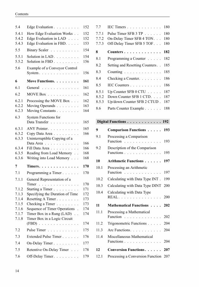
Contents
17
214 Watchdog Interrupts 374
2141 Handling Watchdog Interrupts 3752142 Configuring Watchdog Interrupts
with STEP 7 376
215 Hardware Interrupts 376
2151 Generating a Hardware Interrupt 3762152 Servicing Hardware Interrupts 3772153 Configuring Hardware Interrupts
with STEP 7 378
216 DPV1 Interrupts 378
217 Multiprocessor Interrupt 380
218 Synchronous Cycle Interrupts 381
2181 Processing the Synchronous Cycle Interrupts 381
2182 Isochrone Updating Of Process Image 382
2183 Configuration of Synchronous Cycle Interrupts with STEP 7 383
219 Handling Interrupt Events 383
2191 Disabling and Enabling interrupts 3832192 Delaying and Enabling Interrupts 3842193 Reading additional Interrupt
Information 385
22 Start-up Characteristics 387
221 General Remarks 387
2211 Operating Modes 3872212 HOLD Mode 3882213 Disabling the Output Modules 3882214 Restart Organization Blocks 388
222 Power-Up 389
2221 STOP Mode 3892222 Memory Reset 3892223 Restoring the factory settings 3902224 Retentivity 3902225 Restart Parameterization 390
223 Types of Restart 391
2231 START-UP Mode 3912232 Cold Restart 3932233 Warm Restart 3932234 Hot Restart 394
224 Ascertaining a Module Address 394
225 Parameterizing Modules 397
2251 General remarks on parameterizing modules 397
2252 System Blocks for Module Parameterization 399
2253 Blocks for Transmitting Data Records 401
23 Error Handling 404
231 Synchronous Errors 404
232 Synchronous Error Handling 406
2321 Error Filters 4062322 Masking Synchronous Errors 4072323 Unmasking Synchronous Errors 4082324 Reading the Error Register 4082325 Entering a Substitute Value 408
233 Asynchronous Errors 408
234 System Diagnostics 411
2341 Diagnostic Events and Diagnostic Buffer 411
2342 Writing User Entries in theDiagnostic Buffer 411
2343 Evaluating Diagnostic Interrupts 4122344 Reading the System Status List 412
235 Web Server 415
2351 Activating the Web server 4152352 Reading out Web information 4152353 Web information 415
Appendix 417
24 Supplements to Graphic Programming 418
241 Block Protection 418
242 Indirect Addressing 419
2421 Pointers General Remarks 4192422 Area Pointer 4192423 DB Pointer 4192424 ANY Pointer 4212425 ldquoVariablerdquo ANY Pointer 421
243 Brief Description of the ldquoMessage Frame Examplerdquo 422
Contents
18
25 Block Libraries 426
251 Organization Blocks 426
252 System Function Blocks 427
253 IEC Function Blocks 430
254 S5-S7 Converting Blocks 431
255 TI-S7 Converting Blocks 432
256 PID Control Blocks 433
257 Communication Blocks 433
258 Miscellaneous Blocks 434
259 SIMATIC_NET_CP 434
2510 Redundant IO MGP V31 435
2511 Redundant IO CGP V40 435
2512 Redundant IO CGP V51 435
26 Function Set LAD 436
261 Basic Functions 436
262 Digital Functions 437
263 Program Flow Control 439
27 Function Set FBD 440
271 Basic Functions 440
272 Digital Functions 441
273 Program Flow Control 443
Index 444
Abbreviations 451
Introduction
19
Introduction
This portion of the book provides an overview of the SIMATIC S7-300400
The S7-300400 programmable controller is of modular design The modules with which it is configured can be central (in the vicinity of the CPU) or distributed without any special set-tings or parameter assignments having to be made In SIMATIC S7 systems distributed IO is an integral part of the system The CPU with its various memory areas forms the hardware basis for processing of the user programs A load memory contains the complete user pro-gram the parts of the program relevant to its execution at any given time are in a work mem-ory whose short access times are the prerequi-site for fast program processing
STEP 7 is the programming software for S7-300400 and the automation tool is the SIMATIC Manager The SIMATIC Manager is an application for the Windows operating sys-tems from Microsoft and contains all functions needed to set up a project When necessary the SIMATIC Manager starts additional tools for example to configure stations initialize mod-ules and to write and test programs
You formulate your automation solution in the STEP 7 programming languages The SIMATIC S7 program is structured that is to say it consists of blocks with defined functions that are composed of networks or rungs Differ-ent priority classes allow a graduated interrupt-ibility of the user program currently executing STEP 7 works with variables of various data types starting with binary variables (data type BOOL) through digital variables (eg data type INT or REAL for computing tasks) up to com-plex data types such as arrays or structures (combinations of variables of different types to form a single variable)
The first chapter contains an overview of the hardware in an S7-300400 programmable con-troller and the second chapter contains an over-view of the STEP 7 programming software The basis for the description is the function scope for STEP 7 Version 55
Chapter 3 ldquoSIMATIC S7 Programrdquo serves as an introduction to the most important elements of an S7 program and shows the programming of individual blocks in the programming lan-guages LAD and FBD The functions and oper-ations of LAD and FBD are then described in the subsequent chapters of the book All the descriptions are explained using brief exam-ples
1 SIMATIC S7-300400Programmable ControllerStructure of the programmable controller distributed IO communications module addresses operand areas
2 STEP 7 Programming SoftwareSIMATIC Manager processing a project configuring a station configuring a net-work writing programs (symbol table program editor) switching online testing programs
3 SIMATIC S7 ProgramProgram processing with priority classes program blocks addressing variables programming blocks with LAD and FBD variables and constants data types (over-view)
1 SIMATIC S7-300400 Programmable Controller
20
1 SIMATIC S7-300400 Programmable Controller
11 Structure of the Programmable Controller
111 Components
The SIMATIC S7-300400 is a modular pro-grammable controller comprising the following components
b RacksAccommodate the modules and connect them to each other
b Power supply (PS)Provides the internal supply voltages
b Central processing unit (CPU)Stores and processes the user program
b Interface modules (IMs)Connect the racks to one another
b Signal modules (SMs)Adapt the signals from the system to the internal signal level or control actuators via digital and analog signals
b Function modules (FMs)Execute complex or time-critical processes independently of the CPU
b Communications processors (CPs)Establish the connection to subsidiary net-works (subnets)
b SubnetsConnect programmable controllers to each other or to other devices
A programmable controller (or station) may consist of several racks which are linked to one another via bus cables The power supply CPU and IO modules (SMs FMs and CPs) are plugged into the central rack If there is not enough room in the central rack for the IO modules or if you want some or all IO modules to be separate from the central rack expansion racks are available which are connected to the central rack via interface modules (Figure 11)
It is also possible to connect distributed IO to a station (see Chapter 121 ldquoPROFIBUS DPrdquo)
The racks connect the modules with two buses the IO bus (or P bus) and the communication bus (or K bus) The IO bus is designed for high-speed exchange of input and output sig-nals the communication bus for the exchange of large amounts of data The communication bus connects the CPU and the programming device interface (MPI) with function modules and communications processors
112 S7-300 Station
Centralized configuration
In an S7-300 controller as many as 8 IO mod-ules can be plugged into the central rack Should this single-tier configuration prove insufficient you have two options for control-lers equipped with a CPU 313 or higher
b A two-tier configuration (with IM 365 up to 1 meter between racks) or
b A configuration of up to four tiers (with IM 360 and IM 361 up to 10 meters between racks)
You can operate a maximum of 8 modules in a rack The number of modules may be limited by the maximum permissible current per rack which is 12 A
The modules are linked to one another via a backplane bus which combines the functions of the P and K buses
Local bus segment
A special feature regarding configuration is the use of the FM 356 application module An FM 356 is able to ldquosplitrdquo a modules backplane bus and to take over control of the remaining mod-ules in the split-off ldquolocal bus segmentrdquo itself The limitations mentioned above regarding the
11 Structure of the Programmable Controller
21
Figure 11 Hardware Configuration for S7-300400
1 SIMATIC S7-300400 Programmable Controller
22
number of modules and the power consumption also apply in this case
Standard CPUs
The standard CPUs are available in versions that differ with regard to memory capacity and processing speed They range from the ldquosmall-estrdquo CPU 312 for lower-end applications with moderate processing speed requirements up to the CPU 319-3 PNDP with its large program memory and high processing performance for cross-sector automation tasks Equipped with the relevant interfaces some CPUs can be used for central control of the distributed IO via PROFIBUS and PROFINET A micro memory card (MMC) is required for operating the stan-dard CPUs ndash as with all innovated S7-300-CPUs This medium opens up new application possibilities compared to the previously used memory card (see Chapter 116 ldquoCPU Memory Areasrdquo)
The now discontinued CPU 318 can be re-placed by the CPUs 317 and 319
Compact CPUs
The 3xxC CPUs permit construction of com-pact mini programmable controllers Depend-ing on the version they already contain
b Integral IOsDigital and analog inputsoutputs
b Integral technology functionsCounting measurement control position-ing
b Integral communications interfacesPROFIBUS DP master or slave point-to-point coupling (PtP)
The technological functions are system blocks which use the onboard IO of the CPU
Technology CPUs
The CPUs 3xxT combine open-loop control functions with simple motion control functions The open-loop control component is designed as in a standard CPU It is configured parame-terized and programmed using STEP 7 The technology objects and the motion control com-ponent require the optional S7-Technology
package that is integrated in the SIMATIC Manager after installation
The Technology CPUs have a PROFIBUS DP interface that allows operation as DP master or DP slave The CPUs are used for cross-sector automation tasks in series mechanical equip-ment manufacture special mechanical equip-ment manufacture and plant building
Failsafe CPUs
The CPUs 3xxF are used in production plants with increased safety requirements The rele-vant PROFIBUS and PROFINET interfaces al-low the operation of safety-related distributed IO using the PROFIsafe bus profile (see ldquoSafety Integrated for the manufacturing industryrdquo un-der 115 ldquoSafety-related SIMATICrdquo) Standard modules for normal applications can be used parallel to safety-related operation
SIPLUS
The SIPLUS product family offers modules that can be used in harsh environments The SI-PLUS components are based on standard devic-es which have been specially converted for the respective application for example for an ex-tended temperature range increased resistance to vibration and shock or voltage ranges differ-ing from the standard Please therefore note the technical data for the respective SIPLUS mod-ule In order to carry out the configuration with STEP 7 use the equivalent type (the standard module on which it is based) this is specified for example on the modules nameplate
113 S7-400 station
Centralized configuration
The controller rack for the S7-400 is available in the UR1 (18 slots) UR2 (9 slots) and CR3 (4 slots) versions UR1 and UR2 can also be used as expansion racks The power supply and the CPU also occupy slots in the racks possibly even two or more per module If necessary the number of slots available can be increased using expansion racks UR1 and ER1 have 18 slots each UR2 and ER2 have 9 each
The IM 460-1 and IM 461-1 interface modules make it possible to have one expansion rack per
11 Structure of the Programmable Controller
23
interface up to 15 meters from the central rack including the 5 V supply voltage In addition as many as four expansion racks can be operated up to 5 meters away using IM 460-0 and IM 461-0 interface modules And finally IM 460-3 and IM 461-3 or IM 460-4 and 461-4 interface modules can be used to operate as many as four expansion racks at a distance of up to 100 or 600 meters away
A maximum of 21 expansion racks can be con-nected to a central rack To distinguish between racks you set the number of the rack on the coding switch of the receiving IM
The backplane bus consists of a parallel P bus and a serial K bus Expansion racks ER1 and ER2 are designed for ldquosimplerdquo signal modules which generate no hardware interrupts do not have to be supplied with 24 V voltage via the P bus require no back-up voltage and have no K bus connection The K bus is in racks UR1 UR2 and CR2 either when these racks are used as central racks or expansion racks with the numbers 1 to 6
Segmented rack
A special feature is the segmented rack CR2 The rack can accommodate two CPUs with a shared power supply while keeping them func-tionally separate The two CPUs can exchange data with one another via the K bus but have completely separate P buses for their own sig-nal modules
Multicomputing
In an S7-400 as many as 4 specially designed CPUs in a UR central rack can take part in mul-ticomputing Each module in this station is assigned to only one CPU both with its address and its interrupts For further details see Chap-ters 2036 ldquoMulticomputingrdquo and 217 ldquoMulti-processor Interruptrdquo
Connecting SIMATIC S5 modules
The IM 463-2 interface module allows you to connect S5 expansion units (EG 183U EG 185U EG 186U as well as ER 701-2 and ER 701-3) to an S7-400 and also allows central-ized expansion of the expansion units An IM 314 in the S5 expansion unit handles the link
You can operate all analog and digital modules allowed in these expansion units An S7-400 can accommodate as many as four IM 463-2 interface modules as many as four S5 expan-sion units can be connected in a distributed con-figuration to each of an IM 463-2s two inter-faces
114 Fault-tolerant SIMATIC
Two designs of SIMATIC S7 fault-tolerant automation systems are available for applica-tions with high fault tolerance demands for machines and processes software redundancy and S7-400HFH
Software redundancy
Using SIMATIC S7-300400 standard compo-nents you can establish a software-based redundant system with a master station control-ling the process and a standby station assuming control in the event of the master failing
Fault tolerance through software redundancy is suitable for slow processes because transfer to the standby station can require several seconds depending on the configuration of the program-mable controllers The process signals are ldquofro-zenrdquo during this time The standby station then continues operation with the data last valid in the master station
Redundancy of the inputoutput modules is implemented with distributed IO (ET 200M with IM 153-2 interface module for redundant PROFIBUS DP) The software redundancy can be configured with STEP 7 Version 52 and higher
Fault-tolerant SIMATIC S7-400H
The SIMATIC S7-400H is a fault-tolerant pro-grammable controller with redundant configu-ration comprising two central racks each with an H CPU and a synchronization module for data comparison via fiber optic cable Both controllers operate in ldquohot standbyrdquo mode in the event of a fault the intact controller assumes operation alone via automatic bump-less transfer The UR2-H mounting rack with two times nine slots makes it possible to estab-lish a fault-tolerant system in a single mounting rack
1 SIMATIC S7-300400 Programmable Controller
24
The IO can have normal availability (single-channel single-sided configuration) or enhanced availability (single-channel switched configuration withET 200M) Communication is carried out over a simple or a redundant bus
The user program is the same as that for a non-redundant controller the redundancy function is handled exclusively by the hardware and is invisible to the user The software package required for configuration is included in STEP 7 V53 and later The provided standard librar-ies Redundant IO contain blocks for supporting the redundant IO
115 Safety-related SIMATIC
Failsafe automation systems control processes in which the safe state can be achieved by direct switching off They are used in plants with increased safety requirements
The safety functions are located as appropriate in the safety-related user program of a corre-spondingly designed CPU and in the failsafe input and output modules An F-CPU complies with the safety requirements up to AK 6 in accor-dance with DIN V 19250DIN V VDE 0801 up to SIL 3 in accordance with IEC 61508 and up to Category 4 in accordance with EN 954-1 Safety functions can be executed parallel to a non-safety-related user program in the same CPU
Safety-related communication over PROFIBUS DP ndash also over PROFINET IO with S7 Distrib-uted Safety ndash uses the PROFIsafe bus profile This permits transmission of safety-related and non-safety-related data on a single bus cable
Safety Integrated for the manufacturing industry
S7 Distributed Safety is a failsafe automation system for the protection of machines and per-sonnel mainly for applications with machine controls and in the process industry
CPUs from the SIMATIC S7-300 S7-400 and ET 200S ranges are currently available as F-CPUs The safety-related IO modules are con-nected to S7-400 over PROFIBUS DP or PROFINET IO using the safety-related PROFIsafe bus profile With S7-300 and ET
200S use of safety-related IO modules is addi-tionally possible in the central rack
The hardware configuration and programming of the non-safety-related user program are car-ried out using the standard applications of STEP 7
The SIMATIC S7 Distributed Safety option package is required to program the safety-related parts of the program With this option package you can use the F-LAD or F-FBD pro-gramming languages to create the blocks which contain the safety-related program Interfacing to the IO is carried out using the process image as with the standard program S7 Distributed Safety also includes a library with TUumlV-certi-fied safety blocks There is an additional library available with F-blocks for press and burner controls
The safety-related user program can be exe-cuted parallel to the standard user program If an error is detected in the safety-related part of the program the CPU enters the STOP state
Safety Integrated for the process industry
S7 FFH Systems is a failsafe automation sys-tem based on S7-400 mainly for applications in the process industry The safety-related IO modules are connected over PROFIBUS DP using the safety-related PROFIsafe bus profile
An S7-400 F-CPU is provided with the safety-related control functions by application of an S7 F Systems Runtime license A non-safety-relat-ed user program can be executed parallel to the safety-related plant unit
In addition to fail-safety the S7-400FH also provides increased availability If a detected fault results in a STOP of the master CPU a re-action-free switch is made to the CPU running in hot standby mode The S7 H Systems option package is additionally required for operation as S7-400FH
The hardware configuration and programming of the non-safety-related user program are car-ried out using the standard applications of STEP 7
The S7 F Systems option package is addition-ally required for programming the safety-related program parts and additionally the
11 Structure of the Programmable Controller
25
CFC option package V50 SP3 and higher and the S7-SCL option package V50 and higher
The safety-related program is programmed using CFC (Continuous Function Chart) Pro-grammed safety-related function blocks from the supplied F-library can be called and inter-connected in this manner In addition to func-tions for programming safety functions they also contain functions for error detection and response In the event of faults and failures this guarantees that the failsafe system is held in a safe state or is transferred to a safe state If a fault is detected in the safety program the safety-related part of the plant is switched off whereas the remaining part can continue to operate
Failsafe IO
Failsafe signal modules (F-modules or F-submodules) are required for safety operation Failsafety is achieved with the integral safety functions and appropriate wiring of the sensors and actuators
The F-modules can also be used in standard applications with increased diagnostics require-ments The F-modules can be operated in redundant mode to increase the availability both in standard and safety operation with S7 FFH systems
The failsafe IO is available in various versions
b The failsafe signal modules of S7-300 design are used in the ET 200M distributed IO device or ndash with S7-Distributed Safety ndash also centrally
b Failsafe IO modules are available for the distributed IO devices in the designs ET 200S ET 200pro and ET 200eco
b For the ET 200S and ET 200pro distributed IO devices failsafe interface modules are also available as F-CPUs
b Failsafe DP standard slaves and ndash with S7-Distributed Safety also IO standard devices ndash can be used which can handle the PROFI-safe bus profile
Failsafe CPUs and signal modules are also available in SIPLUS design
116 CPU Memory Areas
Figure 12 shows the memory areas in the pro-gramming device the CPU and the signal mod-ules which are important for your program
The programming device contains the offline data These consist of the user program (pro-gram code and user data) the system data (eg hardware network and interconnection config-urations) and further project-specific data such as symbol tables and comments
The online data consist of the user program and the system data on the CPU and are accommo-dated in two areas namely load memory and work memory In addition the system memory is also present here
The IO modules contain memories for the sig-nal state of the inputs and outputs
The CPUs have a slot for a plug-in memory sub-module The load memory or parts thereof is located here (see ldquoPhysical design of CPU memoryrdquo further below) The memory sub-module is designed as a memory card (S7-400 CPUs) or as a micro memory card (S7-300 CPUs and ET200 CPUs derived from these) The firmware of the CPU operating system can also be updated using the memory submodule
Memory card
The memory module for the S7-400 CPUs is the memory card (MC) There are two types of memory card RAM cards and flash EPROM cards
If you want to expand load memory only use a RAM card A RAM card allows you to modify the entire user program online This is neces-sary for example when testing and starting up larger programs RAM memory cards lose their contents when unplugged
If you want to protect your user program includ-ing configuration data and module parametersagainst power failure following testing and starting up even without a backup battery use a flash EPROM card In this case load the entire program offline onto the flash EPROM card with the card plugged into the programming device With the relevant CPUs you can also load the program online with the memory card plugged into the CPU
1 SIMATIC S7-300400 Programmable Controller
26
Micro memory card
The memory submodule for the newer S7-300 CPUs is a micro memory card (MMC) The data on the MMC are saved non-volatile but can be read written and deleted as with a RAM This response permits data backup without a battery
The complete load memory is present on the MMC meaning that an MMC is always required for operation The MMC can be used as a portable memory medium for user pro-grams or firmware updates Using special sys-tem functions you can read or write data blocks on the MMC from the user program for exam-ple to read recipes from the MMC or to create a
measured-value archive on the MMC and to provide it with data
Load memory
The entire user program including configura-tion data (system data) is in the load memory The user program is always initially transferred from the programming device to the load mem-ory and from there to the work memory The program in the load memory is not processed as the control program
With a CPU 300 and a CPU ET 200 the load memory is present completely on the micro memory card Thus the contents of the load memory are retained even if the CPU is de-energized
Figure 12 CPU Memory Areas
11 Structure of the Programmable Controller
27
If the load memory with a CPU 400 consists of an integrated RAM or RAM memory card a backup battery is required in order to keep the user program retentive With an integrated EEPROM or a plug-in flash EPROM memory card as the load memory the CPU can be oper-ated without battery backup
From STEP 7 V51 onwards and with appro-priately designed CPUs you can save the com-plete project data as a compressed archive file in the load memory (see Chapter 222 ldquoManag-ing Reorganizing and Archivingrdquo)
Work memory
Work memory is designed in the form of high-speed RAM fully integrated in the CPU The operating system of the CPU copies the pro-gram code ldquorelevant to executionrdquo and the user data into the work memory ldquoRelevantrdquo is a characteristic of the existing objects and does not mean that a particular code block will nec-essarily be called and executed The ldquoactualrdquo control program is executed in the work mem-ory
Depending on the product the work memory can be designed either as a correlated area or divided according to program and data memo-ries where the latter can also be divided into retentive and non-retentive memories
When uploading the user program into the pro-gramming device the blocks are fetched from the load memory supplemented by the actual values of the data operands from the work mem-ory (further information can be found in Sections 264 ldquoLoading the User Program into the CPUrdquo and 265 ldquoBlock Handlingrdquo)
System memory
System memory contains the addresses (vari-ables) that you access in your program The addresses are combined into areas (address areas) containing a CPU-specific number of addresses Addresses may be for example inputs used to scan the signal states of momen-tary-contact switches and limit switches and outputs that you can use to control contactors and lamps
The system memory on a CPU contains the fol-lowing address areas
b Inputs (I)Inputs are an image (ldquoprocess imagerdquo) of the digital input modules
b Outputs (Q)Outputs are an image (ldquoprocess imagerdquo) of the digital output modules
b Bit memories (M) are information stores which are directly accessible from any point in the user pro-gram
b Timers (T)Timers are locations used to implement waiting and monitoring times
b Counters (Z)Counters are software-level locations which can be used for up and down counting
b Temporary local data (L)Locations used as dynamic intermediate buffers during block processing The tem-porary local data are located in the L stack which the CPU occupies dynamically dur-ing program execution
The letters enclosed in parentheses represent the abbreviations to be used for the different addresses when writing programs You may also assign a symbol to each variable and then use the symbol in place of the address identifier
The system memory also contains buffers for communication jobs and system messages (diagnostics buffer) The size of these data buff-ers as well as the size of the process image and the L stack are parameterizable on certain CPUs
Physical design of CPU memory
The physical design of the load memory is dif-ferent for the various types of CPU (Figure 13)
A CPU 300 or CPU ET 200 does not have an integrated load memory A micro memory card containing the load memory must always be in-serted to permit operation The load memory can be written and read like a RAM The phys-ical design means that the number of write op-erations is limited (no cyclic writing by user program) You can use the menu command COPY RAM TO ROM to transfer the current values of the data operands from the work memory to the load memory
1 SIMATIC S7-300400 Programmable Controller
28
With a CPU 300 with firmware version V2012 or later the work memory for the user data con-sists of a retentive part and a non-retentive part The control program is also present in the non-retentive part
The integrated RAM load memory in a CPU 400 is designed for small programs or for mod-ification of individual blocks if the load mem-ory is a flash EPROM memory card If the com-plete control program is larger than the inte-grated load memory you require a RAM mem-ory card for testing The tested program is then transmitted by the programming device to a flash EPROM memory card which you insert into the CPU for operation
The work memory of a CPU 400 is divided into two parts One part saves the program code the
other the user data The system and work mem-ories in a CPU 400 constitute one (physical) unit The system and work memories in the S7-400 CPUs constitute one (physical) unit If for example the size of the process image changes this has effects on the size of the work memory
12 Distributed IO
Distributed IO refers to modules connected via PROFIBUS DP or PROFINET IO PROFIBUS DP uses the PROFIBUS subnetwork for data transmission PROFINET IO the Industrial Ethernet subnetwork (for further information see Chapter 132 ldquoSubnetsrdquo)
Figure 13 Physical Design of CPU Memory
12 Distributed IO
29
121 PROFIBUS DP
PROFIBUS DP provides a standardized inter-face for transferring predominantly binary pro-cess data between an ldquointerface modulerdquo in the (central) programmable controller and the field devices This ldquointerface modulerdquo is called the DP master and the field devices are the DP slaves
The DP master and all the slaves it controls form a DP master system There can be up to 32 stations in one segment and up to 127 stations in the entire network A DP master can control a number of DP slaves specific to itself You can also connect programming devices to the PROFIBUS DP network as well as for exam-ple devices for operator control and monitor-ing ET 200 devices or SIMATIC S5 DP slaves
DP master system
PROFIBUS DP is usually operated as a ldquomono master systemrdquo that is one DP master controls several DP slaves The DP master is the only master on the bus with the exception of a tem-porarily available programming device (diag-nostics and service device) The DP master and the DP slaves assigned to it form a DP master system (Figure 14)
You can also install several DP master systems on one PROFIBUS subnet (multi master sys-
tem) However this increases the response time in individual cases because when a DP master has initialized ldquoitsrdquo DP slaves the access rights fall to the next DP master that in turn initializes ldquoitsrdquo DP slaves etc
You can reduce the response time if a DP mas-ter system contains only a few DP slaves Since it is possible to operate several DP masters in one S7 station you can distribute the DP slaves of a station over several DP master systems In multicomputing every CPU has its own DP master systems
DP master
The DP master is the active node on the PRO-FIBUS network It exchanges cyclic data with ldquoitsrdquo DP slaves A DP master can be
b A CPU with integral DP master interface or plug-in interface submodule (eg CPU 315-2DP CPU 417)
b An interface module in conjunction with a CPU (eg IM 467)
b A CP in conjunction with a CPU (eg CP 342-5 CP 443-5)
There are ldquoClass 1 mastersrdquo for data exchange in process operation and ldquoClass 2 mastersrdquo for service and diagnostics (eg a programming device)
Figure 14 Components of a PROFIBUS DP Master System in an RS485 Segment
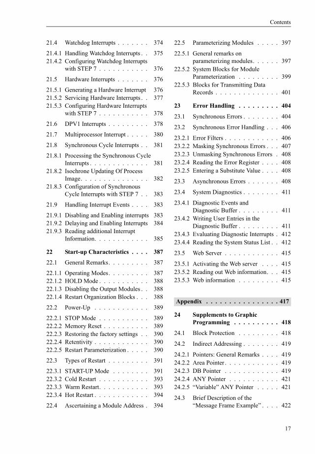
Contents
18
25 Block Libraries 426
251 Organization Blocks 426
252 System Function Blocks 427
253 IEC Function Blocks 430
254 S5-S7 Converting Blocks 431
255 TI-S7 Converting Blocks 432
256 PID Control Blocks 433
257 Communication Blocks 433
258 Miscellaneous Blocks 434
259 SIMATIC_NET_CP 434
2510 Redundant IO MGP V31 435
2511 Redundant IO CGP V40 435
2512 Redundant IO CGP V51 435
26 Function Set LAD 436
261 Basic Functions 436
262 Digital Functions 437
263 Program Flow Control 439
27 Function Set FBD 440
271 Basic Functions 440
272 Digital Functions 441
273 Program Flow Control 443
Index 444
Abbreviations 451
Introduction
19
Introduction
This portion of the book provides an overview of the SIMATIC S7-300400
The S7-300400 programmable controller is of modular design The modules with which it is configured can be central (in the vicinity of the CPU) or distributed without any special set-tings or parameter assignments having to be made In SIMATIC S7 systems distributed IO is an integral part of the system The CPU with its various memory areas forms the hardware basis for processing of the user programs A load memory contains the complete user pro-gram the parts of the program relevant to its execution at any given time are in a work mem-ory whose short access times are the prerequi-site for fast program processing
STEP 7 is the programming software for S7-300400 and the automation tool is the SIMATIC Manager The SIMATIC Manager is an application for the Windows operating sys-tems from Microsoft and contains all functions needed to set up a project When necessary the SIMATIC Manager starts additional tools for example to configure stations initialize mod-ules and to write and test programs
You formulate your automation solution in the STEP 7 programming languages The SIMATIC S7 program is structured that is to say it consists of blocks with defined functions that are composed of networks or rungs Differ-ent priority classes allow a graduated interrupt-ibility of the user program currently executing STEP 7 works with variables of various data types starting with binary variables (data type BOOL) through digital variables (eg data type INT or REAL for computing tasks) up to com-plex data types such as arrays or structures (combinations of variables of different types to form a single variable)
The first chapter contains an overview of the hardware in an S7-300400 programmable con-troller and the second chapter contains an over-view of the STEP 7 programming software The basis for the description is the function scope for STEP 7 Version 55
Chapter 3 ldquoSIMATIC S7 Programrdquo serves as an introduction to the most important elements of an S7 program and shows the programming of individual blocks in the programming lan-guages LAD and FBD The functions and oper-ations of LAD and FBD are then described in the subsequent chapters of the book All the descriptions are explained using brief exam-ples
1 SIMATIC S7-300400Programmable ControllerStructure of the programmable controller distributed IO communications module addresses operand areas
2 STEP 7 Programming SoftwareSIMATIC Manager processing a project configuring a station configuring a net-work writing programs (symbol table program editor) switching online testing programs
3 SIMATIC S7 ProgramProgram processing with priority classes program blocks addressing variables programming blocks with LAD and FBD variables and constants data types (over-view)
1 SIMATIC S7-300400 Programmable Controller
20
1 SIMATIC S7-300400 Programmable Controller
11 Structure of the Programmable Controller
111 Components
The SIMATIC S7-300400 is a modular pro-grammable controller comprising the following components
b RacksAccommodate the modules and connect them to each other
b Power supply (PS)Provides the internal supply voltages
b Central processing unit (CPU)Stores and processes the user program
b Interface modules (IMs)Connect the racks to one another
b Signal modules (SMs)Adapt the signals from the system to the internal signal level or control actuators via digital and analog signals
b Function modules (FMs)Execute complex or time-critical processes independently of the CPU
b Communications processors (CPs)Establish the connection to subsidiary net-works (subnets)
b SubnetsConnect programmable controllers to each other or to other devices
A programmable controller (or station) may consist of several racks which are linked to one another via bus cables The power supply CPU and IO modules (SMs FMs and CPs) are plugged into the central rack If there is not enough room in the central rack for the IO modules or if you want some or all IO modules to be separate from the central rack expansion racks are available which are connected to the central rack via interface modules (Figure 11)
It is also possible to connect distributed IO to a station (see Chapter 121 ldquoPROFIBUS DPrdquo)
The racks connect the modules with two buses the IO bus (or P bus) and the communication bus (or K bus) The IO bus is designed for high-speed exchange of input and output sig-nals the communication bus for the exchange of large amounts of data The communication bus connects the CPU and the programming device interface (MPI) with function modules and communications processors
112 S7-300 Station
Centralized configuration
In an S7-300 controller as many as 8 IO mod-ules can be plugged into the central rack Should this single-tier configuration prove insufficient you have two options for control-lers equipped with a CPU 313 or higher
b A two-tier configuration (with IM 365 up to 1 meter between racks) or
b A configuration of up to four tiers (with IM 360 and IM 361 up to 10 meters between racks)
You can operate a maximum of 8 modules in a rack The number of modules may be limited by the maximum permissible current per rack which is 12 A
The modules are linked to one another via a backplane bus which combines the functions of the P and K buses
Local bus segment
A special feature regarding configuration is the use of the FM 356 application module An FM 356 is able to ldquosplitrdquo a modules backplane bus and to take over control of the remaining mod-ules in the split-off ldquolocal bus segmentrdquo itself The limitations mentioned above regarding the
11 Structure of the Programmable Controller
21
Figure 11 Hardware Configuration for S7-300400
1 SIMATIC S7-300400 Programmable Controller
22
number of modules and the power consumption also apply in this case
Standard CPUs
The standard CPUs are available in versions that differ with regard to memory capacity and processing speed They range from the ldquosmall-estrdquo CPU 312 for lower-end applications with moderate processing speed requirements up to the CPU 319-3 PNDP with its large program memory and high processing performance for cross-sector automation tasks Equipped with the relevant interfaces some CPUs can be used for central control of the distributed IO via PROFIBUS and PROFINET A micro memory card (MMC) is required for operating the stan-dard CPUs ndash as with all innovated S7-300-CPUs This medium opens up new application possibilities compared to the previously used memory card (see Chapter 116 ldquoCPU Memory Areasrdquo)
The now discontinued CPU 318 can be re-placed by the CPUs 317 and 319
Compact CPUs
The 3xxC CPUs permit construction of com-pact mini programmable controllers Depend-ing on the version they already contain
b Integral IOsDigital and analog inputsoutputs
b Integral technology functionsCounting measurement control position-ing
b Integral communications interfacesPROFIBUS DP master or slave point-to-point coupling (PtP)
The technological functions are system blocks which use the onboard IO of the CPU
Technology CPUs
The CPUs 3xxT combine open-loop control functions with simple motion control functions The open-loop control component is designed as in a standard CPU It is configured parame-terized and programmed using STEP 7 The technology objects and the motion control com-ponent require the optional S7-Technology
package that is integrated in the SIMATIC Manager after installation
The Technology CPUs have a PROFIBUS DP interface that allows operation as DP master or DP slave The CPUs are used for cross-sector automation tasks in series mechanical equip-ment manufacture special mechanical equip-ment manufacture and plant building
Failsafe CPUs
The CPUs 3xxF are used in production plants with increased safety requirements The rele-vant PROFIBUS and PROFINET interfaces al-low the operation of safety-related distributed IO using the PROFIsafe bus profile (see ldquoSafety Integrated for the manufacturing industryrdquo un-der 115 ldquoSafety-related SIMATICrdquo) Standard modules for normal applications can be used parallel to safety-related operation
SIPLUS
The SIPLUS product family offers modules that can be used in harsh environments The SI-PLUS components are based on standard devic-es which have been specially converted for the respective application for example for an ex-tended temperature range increased resistance to vibration and shock or voltage ranges differ-ing from the standard Please therefore note the technical data for the respective SIPLUS mod-ule In order to carry out the configuration with STEP 7 use the equivalent type (the standard module on which it is based) this is specified for example on the modules nameplate
113 S7-400 station
Centralized configuration
The controller rack for the S7-400 is available in the UR1 (18 slots) UR2 (9 slots) and CR3 (4 slots) versions UR1 and UR2 can also be used as expansion racks The power supply and the CPU also occupy slots in the racks possibly even two or more per module If necessary the number of slots available can be increased using expansion racks UR1 and ER1 have 18 slots each UR2 and ER2 have 9 each
The IM 460-1 and IM 461-1 interface modules make it possible to have one expansion rack per
11 Structure of the Programmable Controller
23
interface up to 15 meters from the central rack including the 5 V supply voltage In addition as many as four expansion racks can be operated up to 5 meters away using IM 460-0 and IM 461-0 interface modules And finally IM 460-3 and IM 461-3 or IM 460-4 and 461-4 interface modules can be used to operate as many as four expansion racks at a distance of up to 100 or 600 meters away
A maximum of 21 expansion racks can be con-nected to a central rack To distinguish between racks you set the number of the rack on the coding switch of the receiving IM
The backplane bus consists of a parallel P bus and a serial K bus Expansion racks ER1 and ER2 are designed for ldquosimplerdquo signal modules which generate no hardware interrupts do not have to be supplied with 24 V voltage via the P bus require no back-up voltage and have no K bus connection The K bus is in racks UR1 UR2 and CR2 either when these racks are used as central racks or expansion racks with the numbers 1 to 6
Segmented rack
A special feature is the segmented rack CR2 The rack can accommodate two CPUs with a shared power supply while keeping them func-tionally separate The two CPUs can exchange data with one another via the K bus but have completely separate P buses for their own sig-nal modules
Multicomputing
In an S7-400 as many as 4 specially designed CPUs in a UR central rack can take part in mul-ticomputing Each module in this station is assigned to only one CPU both with its address and its interrupts For further details see Chap-ters 2036 ldquoMulticomputingrdquo and 217 ldquoMulti-processor Interruptrdquo
Connecting SIMATIC S5 modules
The IM 463-2 interface module allows you to connect S5 expansion units (EG 183U EG 185U EG 186U as well as ER 701-2 and ER 701-3) to an S7-400 and also allows central-ized expansion of the expansion units An IM 314 in the S5 expansion unit handles the link
You can operate all analog and digital modules allowed in these expansion units An S7-400 can accommodate as many as four IM 463-2 interface modules as many as four S5 expan-sion units can be connected in a distributed con-figuration to each of an IM 463-2s two inter-faces
114 Fault-tolerant SIMATIC
Two designs of SIMATIC S7 fault-tolerant automation systems are available for applica-tions with high fault tolerance demands for machines and processes software redundancy and S7-400HFH
Software redundancy
Using SIMATIC S7-300400 standard compo-nents you can establish a software-based redundant system with a master station control-ling the process and a standby station assuming control in the event of the master failing
Fault tolerance through software redundancy is suitable for slow processes because transfer to the standby station can require several seconds depending on the configuration of the program-mable controllers The process signals are ldquofro-zenrdquo during this time The standby station then continues operation with the data last valid in the master station
Redundancy of the inputoutput modules is implemented with distributed IO (ET 200M with IM 153-2 interface module for redundant PROFIBUS DP) The software redundancy can be configured with STEP 7 Version 52 and higher
Fault-tolerant SIMATIC S7-400H
The SIMATIC S7-400H is a fault-tolerant pro-grammable controller with redundant configu-ration comprising two central racks each with an H CPU and a synchronization module for data comparison via fiber optic cable Both controllers operate in ldquohot standbyrdquo mode in the event of a fault the intact controller assumes operation alone via automatic bump-less transfer The UR2-H mounting rack with two times nine slots makes it possible to estab-lish a fault-tolerant system in a single mounting rack
1 SIMATIC S7-300400 Programmable Controller
24
The IO can have normal availability (single-channel single-sided configuration) or enhanced availability (single-channel switched configuration withET 200M) Communication is carried out over a simple or a redundant bus
The user program is the same as that for a non-redundant controller the redundancy function is handled exclusively by the hardware and is invisible to the user The software package required for configuration is included in STEP 7 V53 and later The provided standard librar-ies Redundant IO contain blocks for supporting the redundant IO
115 Safety-related SIMATIC
Failsafe automation systems control processes in which the safe state can be achieved by direct switching off They are used in plants with increased safety requirements
The safety functions are located as appropriate in the safety-related user program of a corre-spondingly designed CPU and in the failsafe input and output modules An F-CPU complies with the safety requirements up to AK 6 in accor-dance with DIN V 19250DIN V VDE 0801 up to SIL 3 in accordance with IEC 61508 and up to Category 4 in accordance with EN 954-1 Safety functions can be executed parallel to a non-safety-related user program in the same CPU
Safety-related communication over PROFIBUS DP ndash also over PROFINET IO with S7 Distrib-uted Safety ndash uses the PROFIsafe bus profile This permits transmission of safety-related and non-safety-related data on a single bus cable
Safety Integrated for the manufacturing industry
S7 Distributed Safety is a failsafe automation system for the protection of machines and per-sonnel mainly for applications with machine controls and in the process industry
CPUs from the SIMATIC S7-300 S7-400 and ET 200S ranges are currently available as F-CPUs The safety-related IO modules are con-nected to S7-400 over PROFIBUS DP or PROFINET IO using the safety-related PROFIsafe bus profile With S7-300 and ET
200S use of safety-related IO modules is addi-tionally possible in the central rack
The hardware configuration and programming of the non-safety-related user program are car-ried out using the standard applications of STEP 7
The SIMATIC S7 Distributed Safety option package is required to program the safety-related parts of the program With this option package you can use the F-LAD or F-FBD pro-gramming languages to create the blocks which contain the safety-related program Interfacing to the IO is carried out using the process image as with the standard program S7 Distributed Safety also includes a library with TUumlV-certi-fied safety blocks There is an additional library available with F-blocks for press and burner controls
The safety-related user program can be exe-cuted parallel to the standard user program If an error is detected in the safety-related part of the program the CPU enters the STOP state
Safety Integrated for the process industry
S7 FFH Systems is a failsafe automation sys-tem based on S7-400 mainly for applications in the process industry The safety-related IO modules are connected over PROFIBUS DP using the safety-related PROFIsafe bus profile
An S7-400 F-CPU is provided with the safety-related control functions by application of an S7 F Systems Runtime license A non-safety-relat-ed user program can be executed parallel to the safety-related plant unit
In addition to fail-safety the S7-400FH also provides increased availability If a detected fault results in a STOP of the master CPU a re-action-free switch is made to the CPU running in hot standby mode The S7 H Systems option package is additionally required for operation as S7-400FH
The hardware configuration and programming of the non-safety-related user program are car-ried out using the standard applications of STEP 7
The S7 F Systems option package is addition-ally required for programming the safety-related program parts and additionally the
11 Structure of the Programmable Controller
25
CFC option package V50 SP3 and higher and the S7-SCL option package V50 and higher
The safety-related program is programmed using CFC (Continuous Function Chart) Pro-grammed safety-related function blocks from the supplied F-library can be called and inter-connected in this manner In addition to func-tions for programming safety functions they also contain functions for error detection and response In the event of faults and failures this guarantees that the failsafe system is held in a safe state or is transferred to a safe state If a fault is detected in the safety program the safety-related part of the plant is switched off whereas the remaining part can continue to operate
Failsafe IO
Failsafe signal modules (F-modules or F-submodules) are required for safety operation Failsafety is achieved with the integral safety functions and appropriate wiring of the sensors and actuators
The F-modules can also be used in standard applications with increased diagnostics require-ments The F-modules can be operated in redundant mode to increase the availability both in standard and safety operation with S7 FFH systems
The failsafe IO is available in various versions
b The failsafe signal modules of S7-300 design are used in the ET 200M distributed IO device or ndash with S7-Distributed Safety ndash also centrally
b Failsafe IO modules are available for the distributed IO devices in the designs ET 200S ET 200pro and ET 200eco
b For the ET 200S and ET 200pro distributed IO devices failsafe interface modules are also available as F-CPUs
b Failsafe DP standard slaves and ndash with S7-Distributed Safety also IO standard devices ndash can be used which can handle the PROFI-safe bus profile
Failsafe CPUs and signal modules are also available in SIPLUS design
116 CPU Memory Areas
Figure 12 shows the memory areas in the pro-gramming device the CPU and the signal mod-ules which are important for your program
The programming device contains the offline data These consist of the user program (pro-gram code and user data) the system data (eg hardware network and interconnection config-urations) and further project-specific data such as symbol tables and comments
The online data consist of the user program and the system data on the CPU and are accommo-dated in two areas namely load memory and work memory In addition the system memory is also present here
The IO modules contain memories for the sig-nal state of the inputs and outputs
The CPUs have a slot for a plug-in memory sub-module The load memory or parts thereof is located here (see ldquoPhysical design of CPU memoryrdquo further below) The memory sub-module is designed as a memory card (S7-400 CPUs) or as a micro memory card (S7-300 CPUs and ET200 CPUs derived from these) The firmware of the CPU operating system can also be updated using the memory submodule
Memory card
The memory module for the S7-400 CPUs is the memory card (MC) There are two types of memory card RAM cards and flash EPROM cards
If you want to expand load memory only use a RAM card A RAM card allows you to modify the entire user program online This is neces-sary for example when testing and starting up larger programs RAM memory cards lose their contents when unplugged
If you want to protect your user program includ-ing configuration data and module parametersagainst power failure following testing and starting up even without a backup battery use a flash EPROM card In this case load the entire program offline onto the flash EPROM card with the card plugged into the programming device With the relevant CPUs you can also load the program online with the memory card plugged into the CPU
1 SIMATIC S7-300400 Programmable Controller
26
Micro memory card
The memory submodule for the newer S7-300 CPUs is a micro memory card (MMC) The data on the MMC are saved non-volatile but can be read written and deleted as with a RAM This response permits data backup without a battery
The complete load memory is present on the MMC meaning that an MMC is always required for operation The MMC can be used as a portable memory medium for user pro-grams or firmware updates Using special sys-tem functions you can read or write data blocks on the MMC from the user program for exam-ple to read recipes from the MMC or to create a
measured-value archive on the MMC and to provide it with data
Load memory
The entire user program including configura-tion data (system data) is in the load memory The user program is always initially transferred from the programming device to the load mem-ory and from there to the work memory The program in the load memory is not processed as the control program
With a CPU 300 and a CPU ET 200 the load memory is present completely on the micro memory card Thus the contents of the load memory are retained even if the CPU is de-energized
Figure 12 CPU Memory Areas
11 Structure of the Programmable Controller
27
If the load memory with a CPU 400 consists of an integrated RAM or RAM memory card a backup battery is required in order to keep the user program retentive With an integrated EEPROM or a plug-in flash EPROM memory card as the load memory the CPU can be oper-ated without battery backup
From STEP 7 V51 onwards and with appro-priately designed CPUs you can save the com-plete project data as a compressed archive file in the load memory (see Chapter 222 ldquoManag-ing Reorganizing and Archivingrdquo)
Work memory
Work memory is designed in the form of high-speed RAM fully integrated in the CPU The operating system of the CPU copies the pro-gram code ldquorelevant to executionrdquo and the user data into the work memory ldquoRelevantrdquo is a characteristic of the existing objects and does not mean that a particular code block will nec-essarily be called and executed The ldquoactualrdquo control program is executed in the work mem-ory
Depending on the product the work memory can be designed either as a correlated area or divided according to program and data memo-ries where the latter can also be divided into retentive and non-retentive memories
When uploading the user program into the pro-gramming device the blocks are fetched from the load memory supplemented by the actual values of the data operands from the work mem-ory (further information can be found in Sections 264 ldquoLoading the User Program into the CPUrdquo and 265 ldquoBlock Handlingrdquo)
System memory
System memory contains the addresses (vari-ables) that you access in your program The addresses are combined into areas (address areas) containing a CPU-specific number of addresses Addresses may be for example inputs used to scan the signal states of momen-tary-contact switches and limit switches and outputs that you can use to control contactors and lamps
The system memory on a CPU contains the fol-lowing address areas
b Inputs (I)Inputs are an image (ldquoprocess imagerdquo) of the digital input modules
b Outputs (Q)Outputs are an image (ldquoprocess imagerdquo) of the digital output modules
b Bit memories (M) are information stores which are directly accessible from any point in the user pro-gram
b Timers (T)Timers are locations used to implement waiting and monitoring times
b Counters (Z)Counters are software-level locations which can be used for up and down counting
b Temporary local data (L)Locations used as dynamic intermediate buffers during block processing The tem-porary local data are located in the L stack which the CPU occupies dynamically dur-ing program execution
The letters enclosed in parentheses represent the abbreviations to be used for the different addresses when writing programs You may also assign a symbol to each variable and then use the symbol in place of the address identifier
The system memory also contains buffers for communication jobs and system messages (diagnostics buffer) The size of these data buff-ers as well as the size of the process image and the L stack are parameterizable on certain CPUs
Physical design of CPU memory
The physical design of the load memory is dif-ferent for the various types of CPU (Figure 13)
A CPU 300 or CPU ET 200 does not have an integrated load memory A micro memory card containing the load memory must always be in-serted to permit operation The load memory can be written and read like a RAM The phys-ical design means that the number of write op-erations is limited (no cyclic writing by user program) You can use the menu command COPY RAM TO ROM to transfer the current values of the data operands from the work memory to the load memory
1 SIMATIC S7-300400 Programmable Controller
28
With a CPU 300 with firmware version V2012 or later the work memory for the user data con-sists of a retentive part and a non-retentive part The control program is also present in the non-retentive part
The integrated RAM load memory in a CPU 400 is designed for small programs or for mod-ification of individual blocks if the load mem-ory is a flash EPROM memory card If the com-plete control program is larger than the inte-grated load memory you require a RAM mem-ory card for testing The tested program is then transmitted by the programming device to a flash EPROM memory card which you insert into the CPU for operation
The work memory of a CPU 400 is divided into two parts One part saves the program code the
other the user data The system and work mem-ories in a CPU 400 constitute one (physical) unit The system and work memories in the S7-400 CPUs constitute one (physical) unit If for example the size of the process image changes this has effects on the size of the work memory
12 Distributed IO
Distributed IO refers to modules connected via PROFIBUS DP or PROFINET IO PROFIBUS DP uses the PROFIBUS subnetwork for data transmission PROFINET IO the Industrial Ethernet subnetwork (for further information see Chapter 132 ldquoSubnetsrdquo)
Figure 13 Physical Design of CPU Memory
12 Distributed IO
29
121 PROFIBUS DP
PROFIBUS DP provides a standardized inter-face for transferring predominantly binary pro-cess data between an ldquointerface modulerdquo in the (central) programmable controller and the field devices This ldquointerface modulerdquo is called the DP master and the field devices are the DP slaves
The DP master and all the slaves it controls form a DP master system There can be up to 32 stations in one segment and up to 127 stations in the entire network A DP master can control a number of DP slaves specific to itself You can also connect programming devices to the PROFIBUS DP network as well as for exam-ple devices for operator control and monitor-ing ET 200 devices or SIMATIC S5 DP slaves
DP master system
PROFIBUS DP is usually operated as a ldquomono master systemrdquo that is one DP master controls several DP slaves The DP master is the only master on the bus with the exception of a tem-porarily available programming device (diag-nostics and service device) The DP master and the DP slaves assigned to it form a DP master system (Figure 14)
You can also install several DP master systems on one PROFIBUS subnet (multi master sys-
tem) However this increases the response time in individual cases because when a DP master has initialized ldquoitsrdquo DP slaves the access rights fall to the next DP master that in turn initializes ldquoitsrdquo DP slaves etc
You can reduce the response time if a DP mas-ter system contains only a few DP slaves Since it is possible to operate several DP masters in one S7 station you can distribute the DP slaves of a station over several DP master systems In multicomputing every CPU has its own DP master systems
DP master
The DP master is the active node on the PRO-FIBUS network It exchanges cyclic data with ldquoitsrdquo DP slaves A DP master can be
b A CPU with integral DP master interface or plug-in interface submodule (eg CPU 315-2DP CPU 417)
b An interface module in conjunction with a CPU (eg IM 467)
b A CP in conjunction with a CPU (eg CP 342-5 CP 443-5)
There are ldquoClass 1 mastersrdquo for data exchange in process operation and ldquoClass 2 mastersrdquo for service and diagnostics (eg a programming device)
Figure 14 Components of a PROFIBUS DP Master System in an RS485 Segment
Introduction
19
Introduction
This portion of the book provides an overview of the SIMATIC S7-300400
The S7-300400 programmable controller is of modular design The modules with which it is configured can be central (in the vicinity of the CPU) or distributed without any special set-tings or parameter assignments having to be made In SIMATIC S7 systems distributed IO is an integral part of the system The CPU with its various memory areas forms the hardware basis for processing of the user programs A load memory contains the complete user pro-gram the parts of the program relevant to its execution at any given time are in a work mem-ory whose short access times are the prerequi-site for fast program processing
STEP 7 is the programming software for S7-300400 and the automation tool is the SIMATIC Manager The SIMATIC Manager is an application for the Windows operating sys-tems from Microsoft and contains all functions needed to set up a project When necessary the SIMATIC Manager starts additional tools for example to configure stations initialize mod-ules and to write and test programs
You formulate your automation solution in the STEP 7 programming languages The SIMATIC S7 program is structured that is to say it consists of blocks with defined functions that are composed of networks or rungs Differ-ent priority classes allow a graduated interrupt-ibility of the user program currently executing STEP 7 works with variables of various data types starting with binary variables (data type BOOL) through digital variables (eg data type INT or REAL for computing tasks) up to com-plex data types such as arrays or structures (combinations of variables of different types to form a single variable)
The first chapter contains an overview of the hardware in an S7-300400 programmable con-troller and the second chapter contains an over-view of the STEP 7 programming software The basis for the description is the function scope for STEP 7 Version 55
Chapter 3 ldquoSIMATIC S7 Programrdquo serves as an introduction to the most important elements of an S7 program and shows the programming of individual blocks in the programming lan-guages LAD and FBD The functions and oper-ations of LAD and FBD are then described in the subsequent chapters of the book All the descriptions are explained using brief exam-ples
1 SIMATIC S7-300400Programmable ControllerStructure of the programmable controller distributed IO communications module addresses operand areas
2 STEP 7 Programming SoftwareSIMATIC Manager processing a project configuring a station configuring a net-work writing programs (symbol table program editor) switching online testing programs
3 SIMATIC S7 ProgramProgram processing with priority classes program blocks addressing variables programming blocks with LAD and FBD variables and constants data types (over-view)
1 SIMATIC S7-300400 Programmable Controller
20
1 SIMATIC S7-300400 Programmable Controller
11 Structure of the Programmable Controller
111 Components
The SIMATIC S7-300400 is a modular pro-grammable controller comprising the following components
b RacksAccommodate the modules and connect them to each other
b Power supply (PS)Provides the internal supply voltages
b Central processing unit (CPU)Stores and processes the user program
b Interface modules (IMs)Connect the racks to one another
b Signal modules (SMs)Adapt the signals from the system to the internal signal level or control actuators via digital and analog signals
b Function modules (FMs)Execute complex or time-critical processes independently of the CPU
b Communications processors (CPs)Establish the connection to subsidiary net-works (subnets)
b SubnetsConnect programmable controllers to each other or to other devices
A programmable controller (or station) may consist of several racks which are linked to one another via bus cables The power supply CPU and IO modules (SMs FMs and CPs) are plugged into the central rack If there is not enough room in the central rack for the IO modules or if you want some or all IO modules to be separate from the central rack expansion racks are available which are connected to the central rack via interface modules (Figure 11)
It is also possible to connect distributed IO to a station (see Chapter 121 ldquoPROFIBUS DPrdquo)
The racks connect the modules with two buses the IO bus (or P bus) and the communication bus (or K bus) The IO bus is designed for high-speed exchange of input and output sig-nals the communication bus for the exchange of large amounts of data The communication bus connects the CPU and the programming device interface (MPI) with function modules and communications processors
112 S7-300 Station
Centralized configuration
In an S7-300 controller as many as 8 IO mod-ules can be plugged into the central rack Should this single-tier configuration prove insufficient you have two options for control-lers equipped with a CPU 313 or higher
b A two-tier configuration (with IM 365 up to 1 meter between racks) or
b A configuration of up to four tiers (with IM 360 and IM 361 up to 10 meters between racks)
You can operate a maximum of 8 modules in a rack The number of modules may be limited by the maximum permissible current per rack which is 12 A
The modules are linked to one another via a backplane bus which combines the functions of the P and K buses
Local bus segment
A special feature regarding configuration is the use of the FM 356 application module An FM 356 is able to ldquosplitrdquo a modules backplane bus and to take over control of the remaining mod-ules in the split-off ldquolocal bus segmentrdquo itself The limitations mentioned above regarding the
11 Structure of the Programmable Controller
21
Figure 11 Hardware Configuration for S7-300400
1 SIMATIC S7-300400 Programmable Controller
22
number of modules and the power consumption also apply in this case
Standard CPUs
The standard CPUs are available in versions that differ with regard to memory capacity and processing speed They range from the ldquosmall-estrdquo CPU 312 for lower-end applications with moderate processing speed requirements up to the CPU 319-3 PNDP with its large program memory and high processing performance for cross-sector automation tasks Equipped with the relevant interfaces some CPUs can be used for central control of the distributed IO via PROFIBUS and PROFINET A micro memory card (MMC) is required for operating the stan-dard CPUs ndash as with all innovated S7-300-CPUs This medium opens up new application possibilities compared to the previously used memory card (see Chapter 116 ldquoCPU Memory Areasrdquo)
The now discontinued CPU 318 can be re-placed by the CPUs 317 and 319
Compact CPUs
The 3xxC CPUs permit construction of com-pact mini programmable controllers Depend-ing on the version they already contain
b Integral IOsDigital and analog inputsoutputs
b Integral technology functionsCounting measurement control position-ing
b Integral communications interfacesPROFIBUS DP master or slave point-to-point coupling (PtP)
The technological functions are system blocks which use the onboard IO of the CPU
Technology CPUs
The CPUs 3xxT combine open-loop control functions with simple motion control functions The open-loop control component is designed as in a standard CPU It is configured parame-terized and programmed using STEP 7 The technology objects and the motion control com-ponent require the optional S7-Technology
package that is integrated in the SIMATIC Manager after installation
The Technology CPUs have a PROFIBUS DP interface that allows operation as DP master or DP slave The CPUs are used for cross-sector automation tasks in series mechanical equip-ment manufacture special mechanical equip-ment manufacture and plant building
Failsafe CPUs
The CPUs 3xxF are used in production plants with increased safety requirements The rele-vant PROFIBUS and PROFINET interfaces al-low the operation of safety-related distributed IO using the PROFIsafe bus profile (see ldquoSafety Integrated for the manufacturing industryrdquo un-der 115 ldquoSafety-related SIMATICrdquo) Standard modules for normal applications can be used parallel to safety-related operation
SIPLUS
The SIPLUS product family offers modules that can be used in harsh environments The SI-PLUS components are based on standard devic-es which have been specially converted for the respective application for example for an ex-tended temperature range increased resistance to vibration and shock or voltage ranges differ-ing from the standard Please therefore note the technical data for the respective SIPLUS mod-ule In order to carry out the configuration with STEP 7 use the equivalent type (the standard module on which it is based) this is specified for example on the modules nameplate
113 S7-400 station
Centralized configuration
The controller rack for the S7-400 is available in the UR1 (18 slots) UR2 (9 slots) and CR3 (4 slots) versions UR1 and UR2 can also be used as expansion racks The power supply and the CPU also occupy slots in the racks possibly even two or more per module If necessary the number of slots available can be increased using expansion racks UR1 and ER1 have 18 slots each UR2 and ER2 have 9 each
The IM 460-1 and IM 461-1 interface modules make it possible to have one expansion rack per
11 Structure of the Programmable Controller
23
interface up to 15 meters from the central rack including the 5 V supply voltage In addition as many as four expansion racks can be operated up to 5 meters away using IM 460-0 and IM 461-0 interface modules And finally IM 460-3 and IM 461-3 or IM 460-4 and 461-4 interface modules can be used to operate as many as four expansion racks at a distance of up to 100 or 600 meters away
A maximum of 21 expansion racks can be con-nected to a central rack To distinguish between racks you set the number of the rack on the coding switch of the receiving IM
The backplane bus consists of a parallel P bus and a serial K bus Expansion racks ER1 and ER2 are designed for ldquosimplerdquo signal modules which generate no hardware interrupts do not have to be supplied with 24 V voltage via the P bus require no back-up voltage and have no K bus connection The K bus is in racks UR1 UR2 and CR2 either when these racks are used as central racks or expansion racks with the numbers 1 to 6
Segmented rack
A special feature is the segmented rack CR2 The rack can accommodate two CPUs with a shared power supply while keeping them func-tionally separate The two CPUs can exchange data with one another via the K bus but have completely separate P buses for their own sig-nal modules
Multicomputing
In an S7-400 as many as 4 specially designed CPUs in a UR central rack can take part in mul-ticomputing Each module in this station is assigned to only one CPU both with its address and its interrupts For further details see Chap-ters 2036 ldquoMulticomputingrdquo and 217 ldquoMulti-processor Interruptrdquo
Connecting SIMATIC S5 modules
The IM 463-2 interface module allows you to connect S5 expansion units (EG 183U EG 185U EG 186U as well as ER 701-2 and ER 701-3) to an S7-400 and also allows central-ized expansion of the expansion units An IM 314 in the S5 expansion unit handles the link
You can operate all analog and digital modules allowed in these expansion units An S7-400 can accommodate as many as four IM 463-2 interface modules as many as four S5 expan-sion units can be connected in a distributed con-figuration to each of an IM 463-2s two inter-faces
114 Fault-tolerant SIMATIC
Two designs of SIMATIC S7 fault-tolerant automation systems are available for applica-tions with high fault tolerance demands for machines and processes software redundancy and S7-400HFH
Software redundancy
Using SIMATIC S7-300400 standard compo-nents you can establish a software-based redundant system with a master station control-ling the process and a standby station assuming control in the event of the master failing
Fault tolerance through software redundancy is suitable for slow processes because transfer to the standby station can require several seconds depending on the configuration of the program-mable controllers The process signals are ldquofro-zenrdquo during this time The standby station then continues operation with the data last valid in the master station
Redundancy of the inputoutput modules is implemented with distributed IO (ET 200M with IM 153-2 interface module for redundant PROFIBUS DP) The software redundancy can be configured with STEP 7 Version 52 and higher
Fault-tolerant SIMATIC S7-400H
The SIMATIC S7-400H is a fault-tolerant pro-grammable controller with redundant configu-ration comprising two central racks each with an H CPU and a synchronization module for data comparison via fiber optic cable Both controllers operate in ldquohot standbyrdquo mode in the event of a fault the intact controller assumes operation alone via automatic bump-less transfer The UR2-H mounting rack with two times nine slots makes it possible to estab-lish a fault-tolerant system in a single mounting rack
1 SIMATIC S7-300400 Programmable Controller
24
The IO can have normal availability (single-channel single-sided configuration) or enhanced availability (single-channel switched configuration withET 200M) Communication is carried out over a simple or a redundant bus
The user program is the same as that for a non-redundant controller the redundancy function is handled exclusively by the hardware and is invisible to the user The software package required for configuration is included in STEP 7 V53 and later The provided standard librar-ies Redundant IO contain blocks for supporting the redundant IO
115 Safety-related SIMATIC
Failsafe automation systems control processes in which the safe state can be achieved by direct switching off They are used in plants with increased safety requirements
The safety functions are located as appropriate in the safety-related user program of a corre-spondingly designed CPU and in the failsafe input and output modules An F-CPU complies with the safety requirements up to AK 6 in accor-dance with DIN V 19250DIN V VDE 0801 up to SIL 3 in accordance with IEC 61508 and up to Category 4 in accordance with EN 954-1 Safety functions can be executed parallel to a non-safety-related user program in the same CPU
Safety-related communication over PROFIBUS DP ndash also over PROFINET IO with S7 Distrib-uted Safety ndash uses the PROFIsafe bus profile This permits transmission of safety-related and non-safety-related data on a single bus cable
Safety Integrated for the manufacturing industry
S7 Distributed Safety is a failsafe automation system for the protection of machines and per-sonnel mainly for applications with machine controls and in the process industry
CPUs from the SIMATIC S7-300 S7-400 and ET 200S ranges are currently available as F-CPUs The safety-related IO modules are con-nected to S7-400 over PROFIBUS DP or PROFINET IO using the safety-related PROFIsafe bus profile With S7-300 and ET
200S use of safety-related IO modules is addi-tionally possible in the central rack
The hardware configuration and programming of the non-safety-related user program are car-ried out using the standard applications of STEP 7
The SIMATIC S7 Distributed Safety option package is required to program the safety-related parts of the program With this option package you can use the F-LAD or F-FBD pro-gramming languages to create the blocks which contain the safety-related program Interfacing to the IO is carried out using the process image as with the standard program S7 Distributed Safety also includes a library with TUumlV-certi-fied safety blocks There is an additional library available with F-blocks for press and burner controls
The safety-related user program can be exe-cuted parallel to the standard user program If an error is detected in the safety-related part of the program the CPU enters the STOP state
Safety Integrated for the process industry
S7 FFH Systems is a failsafe automation sys-tem based on S7-400 mainly for applications in the process industry The safety-related IO modules are connected over PROFIBUS DP using the safety-related PROFIsafe bus profile
An S7-400 F-CPU is provided with the safety-related control functions by application of an S7 F Systems Runtime license A non-safety-relat-ed user program can be executed parallel to the safety-related plant unit
In addition to fail-safety the S7-400FH also provides increased availability If a detected fault results in a STOP of the master CPU a re-action-free switch is made to the CPU running in hot standby mode The S7 H Systems option package is additionally required for operation as S7-400FH
The hardware configuration and programming of the non-safety-related user program are car-ried out using the standard applications of STEP 7
The S7 F Systems option package is addition-ally required for programming the safety-related program parts and additionally the
11 Structure of the Programmable Controller
25
CFC option package V50 SP3 and higher and the S7-SCL option package V50 and higher
The safety-related program is programmed using CFC (Continuous Function Chart) Pro-grammed safety-related function blocks from the supplied F-library can be called and inter-connected in this manner In addition to func-tions for programming safety functions they also contain functions for error detection and response In the event of faults and failures this guarantees that the failsafe system is held in a safe state or is transferred to a safe state If a fault is detected in the safety program the safety-related part of the plant is switched off whereas the remaining part can continue to operate
Failsafe IO
Failsafe signal modules (F-modules or F-submodules) are required for safety operation Failsafety is achieved with the integral safety functions and appropriate wiring of the sensors and actuators
The F-modules can also be used in standard applications with increased diagnostics require-ments The F-modules can be operated in redundant mode to increase the availability both in standard and safety operation with S7 FFH systems
The failsafe IO is available in various versions
b The failsafe signal modules of S7-300 design are used in the ET 200M distributed IO device or ndash with S7-Distributed Safety ndash also centrally
b Failsafe IO modules are available for the distributed IO devices in the designs ET 200S ET 200pro and ET 200eco
b For the ET 200S and ET 200pro distributed IO devices failsafe interface modules are also available as F-CPUs
b Failsafe DP standard slaves and ndash with S7-Distributed Safety also IO standard devices ndash can be used which can handle the PROFI-safe bus profile
Failsafe CPUs and signal modules are also available in SIPLUS design
116 CPU Memory Areas
Figure 12 shows the memory areas in the pro-gramming device the CPU and the signal mod-ules which are important for your program
The programming device contains the offline data These consist of the user program (pro-gram code and user data) the system data (eg hardware network and interconnection config-urations) and further project-specific data such as symbol tables and comments
The online data consist of the user program and the system data on the CPU and are accommo-dated in two areas namely load memory and work memory In addition the system memory is also present here
The IO modules contain memories for the sig-nal state of the inputs and outputs
The CPUs have a slot for a plug-in memory sub-module The load memory or parts thereof is located here (see ldquoPhysical design of CPU memoryrdquo further below) The memory sub-module is designed as a memory card (S7-400 CPUs) or as a micro memory card (S7-300 CPUs and ET200 CPUs derived from these) The firmware of the CPU operating system can also be updated using the memory submodule
Memory card
The memory module for the S7-400 CPUs is the memory card (MC) There are two types of memory card RAM cards and flash EPROM cards
If you want to expand load memory only use a RAM card A RAM card allows you to modify the entire user program online This is neces-sary for example when testing and starting up larger programs RAM memory cards lose their contents when unplugged
If you want to protect your user program includ-ing configuration data and module parametersagainst power failure following testing and starting up even without a backup battery use a flash EPROM card In this case load the entire program offline onto the flash EPROM card with the card plugged into the programming device With the relevant CPUs you can also load the program online with the memory card plugged into the CPU
1 SIMATIC S7-300400 Programmable Controller
26
Micro memory card
The memory submodule for the newer S7-300 CPUs is a micro memory card (MMC) The data on the MMC are saved non-volatile but can be read written and deleted as with a RAM This response permits data backup without a battery
The complete load memory is present on the MMC meaning that an MMC is always required for operation The MMC can be used as a portable memory medium for user pro-grams or firmware updates Using special sys-tem functions you can read or write data blocks on the MMC from the user program for exam-ple to read recipes from the MMC or to create a
measured-value archive on the MMC and to provide it with data
Load memory
The entire user program including configura-tion data (system data) is in the load memory The user program is always initially transferred from the programming device to the load mem-ory and from there to the work memory The program in the load memory is not processed as the control program
With a CPU 300 and a CPU ET 200 the load memory is present completely on the micro memory card Thus the contents of the load memory are retained even if the CPU is de-energized
Figure 12 CPU Memory Areas
11 Structure of the Programmable Controller
27
If the load memory with a CPU 400 consists of an integrated RAM or RAM memory card a backup battery is required in order to keep the user program retentive With an integrated EEPROM or a plug-in flash EPROM memory card as the load memory the CPU can be oper-ated without battery backup
From STEP 7 V51 onwards and with appro-priately designed CPUs you can save the com-plete project data as a compressed archive file in the load memory (see Chapter 222 ldquoManag-ing Reorganizing and Archivingrdquo)
Work memory
Work memory is designed in the form of high-speed RAM fully integrated in the CPU The operating system of the CPU copies the pro-gram code ldquorelevant to executionrdquo and the user data into the work memory ldquoRelevantrdquo is a characteristic of the existing objects and does not mean that a particular code block will nec-essarily be called and executed The ldquoactualrdquo control program is executed in the work mem-ory
Depending on the product the work memory can be designed either as a correlated area or divided according to program and data memo-ries where the latter can also be divided into retentive and non-retentive memories
When uploading the user program into the pro-gramming device the blocks are fetched from the load memory supplemented by the actual values of the data operands from the work mem-ory (further information can be found in Sections 264 ldquoLoading the User Program into the CPUrdquo and 265 ldquoBlock Handlingrdquo)
System memory
System memory contains the addresses (vari-ables) that you access in your program The addresses are combined into areas (address areas) containing a CPU-specific number of addresses Addresses may be for example inputs used to scan the signal states of momen-tary-contact switches and limit switches and outputs that you can use to control contactors and lamps
The system memory on a CPU contains the fol-lowing address areas
b Inputs (I)Inputs are an image (ldquoprocess imagerdquo) of the digital input modules
b Outputs (Q)Outputs are an image (ldquoprocess imagerdquo) of the digital output modules
b Bit memories (M) are information stores which are directly accessible from any point in the user pro-gram
b Timers (T)Timers are locations used to implement waiting and monitoring times
b Counters (Z)Counters are software-level locations which can be used for up and down counting
b Temporary local data (L)Locations used as dynamic intermediate buffers during block processing The tem-porary local data are located in the L stack which the CPU occupies dynamically dur-ing program execution
The letters enclosed in parentheses represent the abbreviations to be used for the different addresses when writing programs You may also assign a symbol to each variable and then use the symbol in place of the address identifier
The system memory also contains buffers for communication jobs and system messages (diagnostics buffer) The size of these data buff-ers as well as the size of the process image and the L stack are parameterizable on certain CPUs
Physical design of CPU memory
The physical design of the load memory is dif-ferent for the various types of CPU (Figure 13)
A CPU 300 or CPU ET 200 does not have an integrated load memory A micro memory card containing the load memory must always be in-serted to permit operation The load memory can be written and read like a RAM The phys-ical design means that the number of write op-erations is limited (no cyclic writing by user program) You can use the menu command COPY RAM TO ROM to transfer the current values of the data operands from the work memory to the load memory
1 SIMATIC S7-300400 Programmable Controller
28
With a CPU 300 with firmware version V2012 or later the work memory for the user data con-sists of a retentive part and a non-retentive part The control program is also present in the non-retentive part
The integrated RAM load memory in a CPU 400 is designed for small programs or for mod-ification of individual blocks if the load mem-ory is a flash EPROM memory card If the com-plete control program is larger than the inte-grated load memory you require a RAM mem-ory card for testing The tested program is then transmitted by the programming device to a flash EPROM memory card which you insert into the CPU for operation
The work memory of a CPU 400 is divided into two parts One part saves the program code the
other the user data The system and work mem-ories in a CPU 400 constitute one (physical) unit The system and work memories in the S7-400 CPUs constitute one (physical) unit If for example the size of the process image changes this has effects on the size of the work memory
12 Distributed IO
Distributed IO refers to modules connected via PROFIBUS DP or PROFINET IO PROFIBUS DP uses the PROFIBUS subnetwork for data transmission PROFINET IO the Industrial Ethernet subnetwork (for further information see Chapter 132 ldquoSubnetsrdquo)
Figure 13 Physical Design of CPU Memory
12 Distributed IO
29
121 PROFIBUS DP
PROFIBUS DP provides a standardized inter-face for transferring predominantly binary pro-cess data between an ldquointerface modulerdquo in the (central) programmable controller and the field devices This ldquointerface modulerdquo is called the DP master and the field devices are the DP slaves
The DP master and all the slaves it controls form a DP master system There can be up to 32 stations in one segment and up to 127 stations in the entire network A DP master can control a number of DP slaves specific to itself You can also connect programming devices to the PROFIBUS DP network as well as for exam-ple devices for operator control and monitor-ing ET 200 devices or SIMATIC S5 DP slaves
DP master system
PROFIBUS DP is usually operated as a ldquomono master systemrdquo that is one DP master controls several DP slaves The DP master is the only master on the bus with the exception of a tem-porarily available programming device (diag-nostics and service device) The DP master and the DP slaves assigned to it form a DP master system (Figure 14)
You can also install several DP master systems on one PROFIBUS subnet (multi master sys-
tem) However this increases the response time in individual cases because when a DP master has initialized ldquoitsrdquo DP slaves the access rights fall to the next DP master that in turn initializes ldquoitsrdquo DP slaves etc
You can reduce the response time if a DP mas-ter system contains only a few DP slaves Since it is possible to operate several DP masters in one S7 station you can distribute the DP slaves of a station over several DP master systems In multicomputing every CPU has its own DP master systems
DP master
The DP master is the active node on the PRO-FIBUS network It exchanges cyclic data with ldquoitsrdquo DP slaves A DP master can be
b A CPU with integral DP master interface or plug-in interface submodule (eg CPU 315-2DP CPU 417)
b An interface module in conjunction with a CPU (eg IM 467)
b A CP in conjunction with a CPU (eg CP 342-5 CP 443-5)
There are ldquoClass 1 mastersrdquo for data exchange in process operation and ldquoClass 2 mastersrdquo for service and diagnostics (eg a programming device)
Figure 14 Components of a PROFIBUS DP Master System in an RS485 Segment
1 SIMATIC S7-300400 Programmable Controller
20
1 SIMATIC S7-300400 Programmable Controller
11 Structure of the Programmable Controller
111 Components
The SIMATIC S7-300400 is a modular pro-grammable controller comprising the following components
b RacksAccommodate the modules and connect them to each other
b Power supply (PS)Provides the internal supply voltages
b Central processing unit (CPU)Stores and processes the user program
b Interface modules (IMs)Connect the racks to one another
b Signal modules (SMs)Adapt the signals from the system to the internal signal level or control actuators via digital and analog signals
b Function modules (FMs)Execute complex or time-critical processes independently of the CPU
b Communications processors (CPs)Establish the connection to subsidiary net-works (subnets)
b SubnetsConnect programmable controllers to each other or to other devices
A programmable controller (or station) may consist of several racks which are linked to one another via bus cables The power supply CPU and IO modules (SMs FMs and CPs) are plugged into the central rack If there is not enough room in the central rack for the IO modules or if you want some or all IO modules to be separate from the central rack expansion racks are available which are connected to the central rack via interface modules (Figure 11)
It is also possible to connect distributed IO to a station (see Chapter 121 ldquoPROFIBUS DPrdquo)
The racks connect the modules with two buses the IO bus (or P bus) and the communication bus (or K bus) The IO bus is designed for high-speed exchange of input and output sig-nals the communication bus for the exchange of large amounts of data The communication bus connects the CPU and the programming device interface (MPI) with function modules and communications processors
112 S7-300 Station
Centralized configuration
In an S7-300 controller as many as 8 IO mod-ules can be plugged into the central rack Should this single-tier configuration prove insufficient you have two options for control-lers equipped with a CPU 313 or higher
b A two-tier configuration (with IM 365 up to 1 meter between racks) or
b A configuration of up to four tiers (with IM 360 and IM 361 up to 10 meters between racks)
You can operate a maximum of 8 modules in a rack The number of modules may be limited by the maximum permissible current per rack which is 12 A
The modules are linked to one another via a backplane bus which combines the functions of the P and K buses
Local bus segment
A special feature regarding configuration is the use of the FM 356 application module An FM 356 is able to ldquosplitrdquo a modules backplane bus and to take over control of the remaining mod-ules in the split-off ldquolocal bus segmentrdquo itself The limitations mentioned above regarding the
11 Structure of the Programmable Controller
21
Figure 11 Hardware Configuration for S7-300400
1 SIMATIC S7-300400 Programmable Controller
22
number of modules and the power consumption also apply in this case
Standard CPUs
The standard CPUs are available in versions that differ with regard to memory capacity and processing speed They range from the ldquosmall-estrdquo CPU 312 for lower-end applications with moderate processing speed requirements up to the CPU 319-3 PNDP with its large program memory and high processing performance for cross-sector automation tasks Equipped with the relevant interfaces some CPUs can be used for central control of the distributed IO via PROFIBUS and PROFINET A micro memory card (MMC) is required for operating the stan-dard CPUs ndash as with all innovated S7-300-CPUs This medium opens up new application possibilities compared to the previously used memory card (see Chapter 116 ldquoCPU Memory Areasrdquo)
The now discontinued CPU 318 can be re-placed by the CPUs 317 and 319
Compact CPUs
The 3xxC CPUs permit construction of com-pact mini programmable controllers Depend-ing on the version they already contain
b Integral IOsDigital and analog inputsoutputs
b Integral technology functionsCounting measurement control position-ing
b Integral communications interfacesPROFIBUS DP master or slave point-to-point coupling (PtP)
The technological functions are system blocks which use the onboard IO of the CPU
Technology CPUs
The CPUs 3xxT combine open-loop control functions with simple motion control functions The open-loop control component is designed as in a standard CPU It is configured parame-terized and programmed using STEP 7 The technology objects and the motion control com-ponent require the optional S7-Technology
package that is integrated in the SIMATIC Manager after installation
The Technology CPUs have a PROFIBUS DP interface that allows operation as DP master or DP slave The CPUs are used for cross-sector automation tasks in series mechanical equip-ment manufacture special mechanical equip-ment manufacture and plant building
Failsafe CPUs
The CPUs 3xxF are used in production plants with increased safety requirements The rele-vant PROFIBUS and PROFINET interfaces al-low the operation of safety-related distributed IO using the PROFIsafe bus profile (see ldquoSafety Integrated for the manufacturing industryrdquo un-der 115 ldquoSafety-related SIMATICrdquo) Standard modules for normal applications can be used parallel to safety-related operation
SIPLUS
The SIPLUS product family offers modules that can be used in harsh environments The SI-PLUS components are based on standard devic-es which have been specially converted for the respective application for example for an ex-tended temperature range increased resistance to vibration and shock or voltage ranges differ-ing from the standard Please therefore note the technical data for the respective SIPLUS mod-ule In order to carry out the configuration with STEP 7 use the equivalent type (the standard module on which it is based) this is specified for example on the modules nameplate
113 S7-400 station
Centralized configuration
The controller rack for the S7-400 is available in the UR1 (18 slots) UR2 (9 slots) and CR3 (4 slots) versions UR1 and UR2 can also be used as expansion racks The power supply and the CPU also occupy slots in the racks possibly even two or more per module If necessary the number of slots available can be increased using expansion racks UR1 and ER1 have 18 slots each UR2 and ER2 have 9 each
The IM 460-1 and IM 461-1 interface modules make it possible to have one expansion rack per
11 Structure of the Programmable Controller
23
interface up to 15 meters from the central rack including the 5 V supply voltage In addition as many as four expansion racks can be operated up to 5 meters away using IM 460-0 and IM 461-0 interface modules And finally IM 460-3 and IM 461-3 or IM 460-4 and 461-4 interface modules can be used to operate as many as four expansion racks at a distance of up to 100 or 600 meters away
A maximum of 21 expansion racks can be con-nected to a central rack To distinguish between racks you set the number of the rack on the coding switch of the receiving IM
The backplane bus consists of a parallel P bus and a serial K bus Expansion racks ER1 and ER2 are designed for ldquosimplerdquo signal modules which generate no hardware interrupts do not have to be supplied with 24 V voltage via the P bus require no back-up voltage and have no K bus connection The K bus is in racks UR1 UR2 and CR2 either when these racks are used as central racks or expansion racks with the numbers 1 to 6
Segmented rack
A special feature is the segmented rack CR2 The rack can accommodate two CPUs with a shared power supply while keeping them func-tionally separate The two CPUs can exchange data with one another via the K bus but have completely separate P buses for their own sig-nal modules
Multicomputing
In an S7-400 as many as 4 specially designed CPUs in a UR central rack can take part in mul-ticomputing Each module in this station is assigned to only one CPU both with its address and its interrupts For further details see Chap-ters 2036 ldquoMulticomputingrdquo and 217 ldquoMulti-processor Interruptrdquo
Connecting SIMATIC S5 modules
The IM 463-2 interface module allows you to connect S5 expansion units (EG 183U EG 185U EG 186U as well as ER 701-2 and ER 701-3) to an S7-400 and also allows central-ized expansion of the expansion units An IM 314 in the S5 expansion unit handles the link
You can operate all analog and digital modules allowed in these expansion units An S7-400 can accommodate as many as four IM 463-2 interface modules as many as four S5 expan-sion units can be connected in a distributed con-figuration to each of an IM 463-2s two inter-faces
114 Fault-tolerant SIMATIC
Two designs of SIMATIC S7 fault-tolerant automation systems are available for applica-tions with high fault tolerance demands for machines and processes software redundancy and S7-400HFH
Software redundancy
Using SIMATIC S7-300400 standard compo-nents you can establish a software-based redundant system with a master station control-ling the process and a standby station assuming control in the event of the master failing
Fault tolerance through software redundancy is suitable for slow processes because transfer to the standby station can require several seconds depending on the configuration of the program-mable controllers The process signals are ldquofro-zenrdquo during this time The standby station then continues operation with the data last valid in the master station
Redundancy of the inputoutput modules is implemented with distributed IO (ET 200M with IM 153-2 interface module for redundant PROFIBUS DP) The software redundancy can be configured with STEP 7 Version 52 and higher
Fault-tolerant SIMATIC S7-400H
The SIMATIC S7-400H is a fault-tolerant pro-grammable controller with redundant configu-ration comprising two central racks each with an H CPU and a synchronization module for data comparison via fiber optic cable Both controllers operate in ldquohot standbyrdquo mode in the event of a fault the intact controller assumes operation alone via automatic bump-less transfer The UR2-H mounting rack with two times nine slots makes it possible to estab-lish a fault-tolerant system in a single mounting rack
1 SIMATIC S7-300400 Programmable Controller
24
The IO can have normal availability (single-channel single-sided configuration) or enhanced availability (single-channel switched configuration withET 200M) Communication is carried out over a simple or a redundant bus
The user program is the same as that for a non-redundant controller the redundancy function is handled exclusively by the hardware and is invisible to the user The software package required for configuration is included in STEP 7 V53 and later The provided standard librar-ies Redundant IO contain blocks for supporting the redundant IO
115 Safety-related SIMATIC
Failsafe automation systems control processes in which the safe state can be achieved by direct switching off They are used in plants with increased safety requirements
The safety functions are located as appropriate in the safety-related user program of a corre-spondingly designed CPU and in the failsafe input and output modules An F-CPU complies with the safety requirements up to AK 6 in accor-dance with DIN V 19250DIN V VDE 0801 up to SIL 3 in accordance with IEC 61508 and up to Category 4 in accordance with EN 954-1 Safety functions can be executed parallel to a non-safety-related user program in the same CPU
Safety-related communication over PROFIBUS DP ndash also over PROFINET IO with S7 Distrib-uted Safety ndash uses the PROFIsafe bus profile This permits transmission of safety-related and non-safety-related data on a single bus cable
Safety Integrated for the manufacturing industry
S7 Distributed Safety is a failsafe automation system for the protection of machines and per-sonnel mainly for applications with machine controls and in the process industry
CPUs from the SIMATIC S7-300 S7-400 and ET 200S ranges are currently available as F-CPUs The safety-related IO modules are con-nected to S7-400 over PROFIBUS DP or PROFINET IO using the safety-related PROFIsafe bus profile With S7-300 and ET
200S use of safety-related IO modules is addi-tionally possible in the central rack
The hardware configuration and programming of the non-safety-related user program are car-ried out using the standard applications of STEP 7
The SIMATIC S7 Distributed Safety option package is required to program the safety-related parts of the program With this option package you can use the F-LAD or F-FBD pro-gramming languages to create the blocks which contain the safety-related program Interfacing to the IO is carried out using the process image as with the standard program S7 Distributed Safety also includes a library with TUumlV-certi-fied safety blocks There is an additional library available with F-blocks for press and burner controls
The safety-related user program can be exe-cuted parallel to the standard user program If an error is detected in the safety-related part of the program the CPU enters the STOP state
Safety Integrated for the process industry
S7 FFH Systems is a failsafe automation sys-tem based on S7-400 mainly for applications in the process industry The safety-related IO modules are connected over PROFIBUS DP using the safety-related PROFIsafe bus profile
An S7-400 F-CPU is provided with the safety-related control functions by application of an S7 F Systems Runtime license A non-safety-relat-ed user program can be executed parallel to the safety-related plant unit
In addition to fail-safety the S7-400FH also provides increased availability If a detected fault results in a STOP of the master CPU a re-action-free switch is made to the CPU running in hot standby mode The S7 H Systems option package is additionally required for operation as S7-400FH
The hardware configuration and programming of the non-safety-related user program are car-ried out using the standard applications of STEP 7
The S7 F Systems option package is addition-ally required for programming the safety-related program parts and additionally the
11 Structure of the Programmable Controller
25
CFC option package V50 SP3 and higher and the S7-SCL option package V50 and higher
The safety-related program is programmed using CFC (Continuous Function Chart) Pro-grammed safety-related function blocks from the supplied F-library can be called and inter-connected in this manner In addition to func-tions for programming safety functions they also contain functions for error detection and response In the event of faults and failures this guarantees that the failsafe system is held in a safe state or is transferred to a safe state If a fault is detected in the safety program the safety-related part of the plant is switched off whereas the remaining part can continue to operate
Failsafe IO
Failsafe signal modules (F-modules or F-submodules) are required for safety operation Failsafety is achieved with the integral safety functions and appropriate wiring of the sensors and actuators
The F-modules can also be used in standard applications with increased diagnostics require-ments The F-modules can be operated in redundant mode to increase the availability both in standard and safety operation with S7 FFH systems
The failsafe IO is available in various versions
b The failsafe signal modules of S7-300 design are used in the ET 200M distributed IO device or ndash with S7-Distributed Safety ndash also centrally
b Failsafe IO modules are available for the distributed IO devices in the designs ET 200S ET 200pro and ET 200eco
b For the ET 200S and ET 200pro distributed IO devices failsafe interface modules are also available as F-CPUs
b Failsafe DP standard slaves and ndash with S7-Distributed Safety also IO standard devices ndash can be used which can handle the PROFI-safe bus profile
Failsafe CPUs and signal modules are also available in SIPLUS design
116 CPU Memory Areas
Figure 12 shows the memory areas in the pro-gramming device the CPU and the signal mod-ules which are important for your program
The programming device contains the offline data These consist of the user program (pro-gram code and user data) the system data (eg hardware network and interconnection config-urations) and further project-specific data such as symbol tables and comments
The online data consist of the user program and the system data on the CPU and are accommo-dated in two areas namely load memory and work memory In addition the system memory is also present here
The IO modules contain memories for the sig-nal state of the inputs and outputs
The CPUs have a slot for a plug-in memory sub-module The load memory or parts thereof is located here (see ldquoPhysical design of CPU memoryrdquo further below) The memory sub-module is designed as a memory card (S7-400 CPUs) or as a micro memory card (S7-300 CPUs and ET200 CPUs derived from these) The firmware of the CPU operating system can also be updated using the memory submodule
Memory card
The memory module for the S7-400 CPUs is the memory card (MC) There are two types of memory card RAM cards and flash EPROM cards
If you want to expand load memory only use a RAM card A RAM card allows you to modify the entire user program online This is neces-sary for example when testing and starting up larger programs RAM memory cards lose their contents when unplugged
If you want to protect your user program includ-ing configuration data and module parametersagainst power failure following testing and starting up even without a backup battery use a flash EPROM card In this case load the entire program offline onto the flash EPROM card with the card plugged into the programming device With the relevant CPUs you can also load the program online with the memory card plugged into the CPU
1 SIMATIC S7-300400 Programmable Controller
26
Micro memory card
The memory submodule for the newer S7-300 CPUs is a micro memory card (MMC) The data on the MMC are saved non-volatile but can be read written and deleted as with a RAM This response permits data backup without a battery
The complete load memory is present on the MMC meaning that an MMC is always required for operation The MMC can be used as a portable memory medium for user pro-grams or firmware updates Using special sys-tem functions you can read or write data blocks on the MMC from the user program for exam-ple to read recipes from the MMC or to create a
measured-value archive on the MMC and to provide it with data
Load memory
The entire user program including configura-tion data (system data) is in the load memory The user program is always initially transferred from the programming device to the load mem-ory and from there to the work memory The program in the load memory is not processed as the control program
With a CPU 300 and a CPU ET 200 the load memory is present completely on the micro memory card Thus the contents of the load memory are retained even if the CPU is de-energized
Figure 12 CPU Memory Areas
11 Structure of the Programmable Controller
27
If the load memory with a CPU 400 consists of an integrated RAM or RAM memory card a backup battery is required in order to keep the user program retentive With an integrated EEPROM or a plug-in flash EPROM memory card as the load memory the CPU can be oper-ated without battery backup
From STEP 7 V51 onwards and with appro-priately designed CPUs you can save the com-plete project data as a compressed archive file in the load memory (see Chapter 222 ldquoManag-ing Reorganizing and Archivingrdquo)
Work memory
Work memory is designed in the form of high-speed RAM fully integrated in the CPU The operating system of the CPU copies the pro-gram code ldquorelevant to executionrdquo and the user data into the work memory ldquoRelevantrdquo is a characteristic of the existing objects and does not mean that a particular code block will nec-essarily be called and executed The ldquoactualrdquo control program is executed in the work mem-ory
Depending on the product the work memory can be designed either as a correlated area or divided according to program and data memo-ries where the latter can also be divided into retentive and non-retentive memories
When uploading the user program into the pro-gramming device the blocks are fetched from the load memory supplemented by the actual values of the data operands from the work mem-ory (further information can be found in Sections 264 ldquoLoading the User Program into the CPUrdquo and 265 ldquoBlock Handlingrdquo)
System memory
System memory contains the addresses (vari-ables) that you access in your program The addresses are combined into areas (address areas) containing a CPU-specific number of addresses Addresses may be for example inputs used to scan the signal states of momen-tary-contact switches and limit switches and outputs that you can use to control contactors and lamps
The system memory on a CPU contains the fol-lowing address areas
b Inputs (I)Inputs are an image (ldquoprocess imagerdquo) of the digital input modules
b Outputs (Q)Outputs are an image (ldquoprocess imagerdquo) of the digital output modules
b Bit memories (M) are information stores which are directly accessible from any point in the user pro-gram
b Timers (T)Timers are locations used to implement waiting and monitoring times
b Counters (Z)Counters are software-level locations which can be used for up and down counting
b Temporary local data (L)Locations used as dynamic intermediate buffers during block processing The tem-porary local data are located in the L stack which the CPU occupies dynamically dur-ing program execution
The letters enclosed in parentheses represent the abbreviations to be used for the different addresses when writing programs You may also assign a symbol to each variable and then use the symbol in place of the address identifier
The system memory also contains buffers for communication jobs and system messages (diagnostics buffer) The size of these data buff-ers as well as the size of the process image and the L stack are parameterizable on certain CPUs
Physical design of CPU memory
The physical design of the load memory is dif-ferent for the various types of CPU (Figure 13)
A CPU 300 or CPU ET 200 does not have an integrated load memory A micro memory card containing the load memory must always be in-serted to permit operation The load memory can be written and read like a RAM The phys-ical design means that the number of write op-erations is limited (no cyclic writing by user program) You can use the menu command COPY RAM TO ROM to transfer the current values of the data operands from the work memory to the load memory
1 SIMATIC S7-300400 Programmable Controller
28
With a CPU 300 with firmware version V2012 or later the work memory for the user data con-sists of a retentive part and a non-retentive part The control program is also present in the non-retentive part
The integrated RAM load memory in a CPU 400 is designed for small programs or for mod-ification of individual blocks if the load mem-ory is a flash EPROM memory card If the com-plete control program is larger than the inte-grated load memory you require a RAM mem-ory card for testing The tested program is then transmitted by the programming device to a flash EPROM memory card which you insert into the CPU for operation
The work memory of a CPU 400 is divided into two parts One part saves the program code the
other the user data The system and work mem-ories in a CPU 400 constitute one (physical) unit The system and work memories in the S7-400 CPUs constitute one (physical) unit If for example the size of the process image changes this has effects on the size of the work memory
12 Distributed IO
Distributed IO refers to modules connected via PROFIBUS DP or PROFINET IO PROFIBUS DP uses the PROFIBUS subnetwork for data transmission PROFINET IO the Industrial Ethernet subnetwork (for further information see Chapter 132 ldquoSubnetsrdquo)
Figure 13 Physical Design of CPU Memory
12 Distributed IO
29
121 PROFIBUS DP
PROFIBUS DP provides a standardized inter-face for transferring predominantly binary pro-cess data between an ldquointerface modulerdquo in the (central) programmable controller and the field devices This ldquointerface modulerdquo is called the DP master and the field devices are the DP slaves
The DP master and all the slaves it controls form a DP master system There can be up to 32 stations in one segment and up to 127 stations in the entire network A DP master can control a number of DP slaves specific to itself You can also connect programming devices to the PROFIBUS DP network as well as for exam-ple devices for operator control and monitor-ing ET 200 devices or SIMATIC S5 DP slaves
DP master system
PROFIBUS DP is usually operated as a ldquomono master systemrdquo that is one DP master controls several DP slaves The DP master is the only master on the bus with the exception of a tem-porarily available programming device (diag-nostics and service device) The DP master and the DP slaves assigned to it form a DP master system (Figure 14)
You can also install several DP master systems on one PROFIBUS subnet (multi master sys-
tem) However this increases the response time in individual cases because when a DP master has initialized ldquoitsrdquo DP slaves the access rights fall to the next DP master that in turn initializes ldquoitsrdquo DP slaves etc
You can reduce the response time if a DP mas-ter system contains only a few DP slaves Since it is possible to operate several DP masters in one S7 station you can distribute the DP slaves of a station over several DP master systems In multicomputing every CPU has its own DP master systems
DP master
The DP master is the active node on the PRO-FIBUS network It exchanges cyclic data with ldquoitsrdquo DP slaves A DP master can be
b A CPU with integral DP master interface or plug-in interface submodule (eg CPU 315-2DP CPU 417)
b An interface module in conjunction with a CPU (eg IM 467)
b A CP in conjunction with a CPU (eg CP 342-5 CP 443-5)
There are ldquoClass 1 mastersrdquo for data exchange in process operation and ldquoClass 2 mastersrdquo for service and diagnostics (eg a programming device)
Figure 14 Components of a PROFIBUS DP Master System in an RS485 Segment
11 Structure of the Programmable Controller
21
Figure 11 Hardware Configuration for S7-300400
1 SIMATIC S7-300400 Programmable Controller
22
number of modules and the power consumption also apply in this case
Standard CPUs
The standard CPUs are available in versions that differ with regard to memory capacity and processing speed They range from the ldquosmall-estrdquo CPU 312 for lower-end applications with moderate processing speed requirements up to the CPU 319-3 PNDP with its large program memory and high processing performance for cross-sector automation tasks Equipped with the relevant interfaces some CPUs can be used for central control of the distributed IO via PROFIBUS and PROFINET A micro memory card (MMC) is required for operating the stan-dard CPUs ndash as with all innovated S7-300-CPUs This medium opens up new application possibilities compared to the previously used memory card (see Chapter 116 ldquoCPU Memory Areasrdquo)
The now discontinued CPU 318 can be re-placed by the CPUs 317 and 319
Compact CPUs
The 3xxC CPUs permit construction of com-pact mini programmable controllers Depend-ing on the version they already contain
b Integral IOsDigital and analog inputsoutputs
b Integral technology functionsCounting measurement control position-ing
b Integral communications interfacesPROFIBUS DP master or slave point-to-point coupling (PtP)
The technological functions are system blocks which use the onboard IO of the CPU
Technology CPUs
The CPUs 3xxT combine open-loop control functions with simple motion control functions The open-loop control component is designed as in a standard CPU It is configured parame-terized and programmed using STEP 7 The technology objects and the motion control com-ponent require the optional S7-Technology
package that is integrated in the SIMATIC Manager after installation
The Technology CPUs have a PROFIBUS DP interface that allows operation as DP master or DP slave The CPUs are used for cross-sector automation tasks in series mechanical equip-ment manufacture special mechanical equip-ment manufacture and plant building
Failsafe CPUs
The CPUs 3xxF are used in production plants with increased safety requirements The rele-vant PROFIBUS and PROFINET interfaces al-low the operation of safety-related distributed IO using the PROFIsafe bus profile (see ldquoSafety Integrated for the manufacturing industryrdquo un-der 115 ldquoSafety-related SIMATICrdquo) Standard modules for normal applications can be used parallel to safety-related operation
SIPLUS
The SIPLUS product family offers modules that can be used in harsh environments The SI-PLUS components are based on standard devic-es which have been specially converted for the respective application for example for an ex-tended temperature range increased resistance to vibration and shock or voltage ranges differ-ing from the standard Please therefore note the technical data for the respective SIPLUS mod-ule In order to carry out the configuration with STEP 7 use the equivalent type (the standard module on which it is based) this is specified for example on the modules nameplate
113 S7-400 station
Centralized configuration
The controller rack for the S7-400 is available in the UR1 (18 slots) UR2 (9 slots) and CR3 (4 slots) versions UR1 and UR2 can also be used as expansion racks The power supply and the CPU also occupy slots in the racks possibly even two or more per module If necessary the number of slots available can be increased using expansion racks UR1 and ER1 have 18 slots each UR2 and ER2 have 9 each
The IM 460-1 and IM 461-1 interface modules make it possible to have one expansion rack per
11 Structure of the Programmable Controller
23
interface up to 15 meters from the central rack including the 5 V supply voltage In addition as many as four expansion racks can be operated up to 5 meters away using IM 460-0 and IM 461-0 interface modules And finally IM 460-3 and IM 461-3 or IM 460-4 and 461-4 interface modules can be used to operate as many as four expansion racks at a distance of up to 100 or 600 meters away
A maximum of 21 expansion racks can be con-nected to a central rack To distinguish between racks you set the number of the rack on the coding switch of the receiving IM
The backplane bus consists of a parallel P bus and a serial K bus Expansion racks ER1 and ER2 are designed for ldquosimplerdquo signal modules which generate no hardware interrupts do not have to be supplied with 24 V voltage via the P bus require no back-up voltage and have no K bus connection The K bus is in racks UR1 UR2 and CR2 either when these racks are used as central racks or expansion racks with the numbers 1 to 6
Segmented rack
A special feature is the segmented rack CR2 The rack can accommodate two CPUs with a shared power supply while keeping them func-tionally separate The two CPUs can exchange data with one another via the K bus but have completely separate P buses for their own sig-nal modules
Multicomputing
In an S7-400 as many as 4 specially designed CPUs in a UR central rack can take part in mul-ticomputing Each module in this station is assigned to only one CPU both with its address and its interrupts For further details see Chap-ters 2036 ldquoMulticomputingrdquo and 217 ldquoMulti-processor Interruptrdquo
Connecting SIMATIC S5 modules
The IM 463-2 interface module allows you to connect S5 expansion units (EG 183U EG 185U EG 186U as well as ER 701-2 and ER 701-3) to an S7-400 and also allows central-ized expansion of the expansion units An IM 314 in the S5 expansion unit handles the link
You can operate all analog and digital modules allowed in these expansion units An S7-400 can accommodate as many as four IM 463-2 interface modules as many as four S5 expan-sion units can be connected in a distributed con-figuration to each of an IM 463-2s two inter-faces
114 Fault-tolerant SIMATIC
Two designs of SIMATIC S7 fault-tolerant automation systems are available for applica-tions with high fault tolerance demands for machines and processes software redundancy and S7-400HFH
Software redundancy
Using SIMATIC S7-300400 standard compo-nents you can establish a software-based redundant system with a master station control-ling the process and a standby station assuming control in the event of the master failing
Fault tolerance through software redundancy is suitable for slow processes because transfer to the standby station can require several seconds depending on the configuration of the program-mable controllers The process signals are ldquofro-zenrdquo during this time The standby station then continues operation with the data last valid in the master station
Redundancy of the inputoutput modules is implemented with distributed IO (ET 200M with IM 153-2 interface module for redundant PROFIBUS DP) The software redundancy can be configured with STEP 7 Version 52 and higher
Fault-tolerant SIMATIC S7-400H
The SIMATIC S7-400H is a fault-tolerant pro-grammable controller with redundant configu-ration comprising two central racks each with an H CPU and a synchronization module for data comparison via fiber optic cable Both controllers operate in ldquohot standbyrdquo mode in the event of a fault the intact controller assumes operation alone via automatic bump-less transfer The UR2-H mounting rack with two times nine slots makes it possible to estab-lish a fault-tolerant system in a single mounting rack
1 SIMATIC S7-300400 Programmable Controller
24
The IO can have normal availability (single-channel single-sided configuration) or enhanced availability (single-channel switched configuration withET 200M) Communication is carried out over a simple or a redundant bus
The user program is the same as that for a non-redundant controller the redundancy function is handled exclusively by the hardware and is invisible to the user The software package required for configuration is included in STEP 7 V53 and later The provided standard librar-ies Redundant IO contain blocks for supporting the redundant IO
115 Safety-related SIMATIC
Failsafe automation systems control processes in which the safe state can be achieved by direct switching off They are used in plants with increased safety requirements
The safety functions are located as appropriate in the safety-related user program of a corre-spondingly designed CPU and in the failsafe input and output modules An F-CPU complies with the safety requirements up to AK 6 in accor-dance with DIN V 19250DIN V VDE 0801 up to SIL 3 in accordance with IEC 61508 and up to Category 4 in accordance with EN 954-1 Safety functions can be executed parallel to a non-safety-related user program in the same CPU
Safety-related communication over PROFIBUS DP ndash also over PROFINET IO with S7 Distrib-uted Safety ndash uses the PROFIsafe bus profile This permits transmission of safety-related and non-safety-related data on a single bus cable
Safety Integrated for the manufacturing industry
S7 Distributed Safety is a failsafe automation system for the protection of machines and per-sonnel mainly for applications with machine controls and in the process industry
CPUs from the SIMATIC S7-300 S7-400 and ET 200S ranges are currently available as F-CPUs The safety-related IO modules are con-nected to S7-400 over PROFIBUS DP or PROFINET IO using the safety-related PROFIsafe bus profile With S7-300 and ET
200S use of safety-related IO modules is addi-tionally possible in the central rack
The hardware configuration and programming of the non-safety-related user program are car-ried out using the standard applications of STEP 7
The SIMATIC S7 Distributed Safety option package is required to program the safety-related parts of the program With this option package you can use the F-LAD or F-FBD pro-gramming languages to create the blocks which contain the safety-related program Interfacing to the IO is carried out using the process image as with the standard program S7 Distributed Safety also includes a library with TUumlV-certi-fied safety blocks There is an additional library available with F-blocks for press and burner controls
The safety-related user program can be exe-cuted parallel to the standard user program If an error is detected in the safety-related part of the program the CPU enters the STOP state
Safety Integrated for the process industry
S7 FFH Systems is a failsafe automation sys-tem based on S7-400 mainly for applications in the process industry The safety-related IO modules are connected over PROFIBUS DP using the safety-related PROFIsafe bus profile
An S7-400 F-CPU is provided with the safety-related control functions by application of an S7 F Systems Runtime license A non-safety-relat-ed user program can be executed parallel to the safety-related plant unit
In addition to fail-safety the S7-400FH also provides increased availability If a detected fault results in a STOP of the master CPU a re-action-free switch is made to the CPU running in hot standby mode The S7 H Systems option package is additionally required for operation as S7-400FH
The hardware configuration and programming of the non-safety-related user program are car-ried out using the standard applications of STEP 7
The S7 F Systems option package is addition-ally required for programming the safety-related program parts and additionally the
11 Structure of the Programmable Controller
25
CFC option package V50 SP3 and higher and the S7-SCL option package V50 and higher
The safety-related program is programmed using CFC (Continuous Function Chart) Pro-grammed safety-related function blocks from the supplied F-library can be called and inter-connected in this manner In addition to func-tions for programming safety functions they also contain functions for error detection and response In the event of faults and failures this guarantees that the failsafe system is held in a safe state or is transferred to a safe state If a fault is detected in the safety program the safety-related part of the plant is switched off whereas the remaining part can continue to operate
Failsafe IO
Failsafe signal modules (F-modules or F-submodules) are required for safety operation Failsafety is achieved with the integral safety functions and appropriate wiring of the sensors and actuators
The F-modules can also be used in standard applications with increased diagnostics require-ments The F-modules can be operated in redundant mode to increase the availability both in standard and safety operation with S7 FFH systems
The failsafe IO is available in various versions
b The failsafe signal modules of S7-300 design are used in the ET 200M distributed IO device or ndash with S7-Distributed Safety ndash also centrally
b Failsafe IO modules are available for the distributed IO devices in the designs ET 200S ET 200pro and ET 200eco
b For the ET 200S and ET 200pro distributed IO devices failsafe interface modules are also available as F-CPUs
b Failsafe DP standard slaves and ndash with S7-Distributed Safety also IO standard devices ndash can be used which can handle the PROFI-safe bus profile
Failsafe CPUs and signal modules are also available in SIPLUS design
116 CPU Memory Areas
Figure 12 shows the memory areas in the pro-gramming device the CPU and the signal mod-ules which are important for your program
The programming device contains the offline data These consist of the user program (pro-gram code and user data) the system data (eg hardware network and interconnection config-urations) and further project-specific data such as symbol tables and comments
The online data consist of the user program and the system data on the CPU and are accommo-dated in two areas namely load memory and work memory In addition the system memory is also present here
The IO modules contain memories for the sig-nal state of the inputs and outputs
The CPUs have a slot for a plug-in memory sub-module The load memory or parts thereof is located here (see ldquoPhysical design of CPU memoryrdquo further below) The memory sub-module is designed as a memory card (S7-400 CPUs) or as a micro memory card (S7-300 CPUs and ET200 CPUs derived from these) The firmware of the CPU operating system can also be updated using the memory submodule
Memory card
The memory module for the S7-400 CPUs is the memory card (MC) There are two types of memory card RAM cards and flash EPROM cards
If you want to expand load memory only use a RAM card A RAM card allows you to modify the entire user program online This is neces-sary for example when testing and starting up larger programs RAM memory cards lose their contents when unplugged
If you want to protect your user program includ-ing configuration data and module parametersagainst power failure following testing and starting up even without a backup battery use a flash EPROM card In this case load the entire program offline onto the flash EPROM card with the card plugged into the programming device With the relevant CPUs you can also load the program online with the memory card plugged into the CPU
1 SIMATIC S7-300400 Programmable Controller
26
Micro memory card
The memory submodule for the newer S7-300 CPUs is a micro memory card (MMC) The data on the MMC are saved non-volatile but can be read written and deleted as with a RAM This response permits data backup without a battery
The complete load memory is present on the MMC meaning that an MMC is always required for operation The MMC can be used as a portable memory medium for user pro-grams or firmware updates Using special sys-tem functions you can read or write data blocks on the MMC from the user program for exam-ple to read recipes from the MMC or to create a
measured-value archive on the MMC and to provide it with data
Load memory
The entire user program including configura-tion data (system data) is in the load memory The user program is always initially transferred from the programming device to the load mem-ory and from there to the work memory The program in the load memory is not processed as the control program
With a CPU 300 and a CPU ET 200 the load memory is present completely on the micro memory card Thus the contents of the load memory are retained even if the CPU is de-energized
Figure 12 CPU Memory Areas
11 Structure of the Programmable Controller
27
If the load memory with a CPU 400 consists of an integrated RAM or RAM memory card a backup battery is required in order to keep the user program retentive With an integrated EEPROM or a plug-in flash EPROM memory card as the load memory the CPU can be oper-ated without battery backup
From STEP 7 V51 onwards and with appro-priately designed CPUs you can save the com-plete project data as a compressed archive file in the load memory (see Chapter 222 ldquoManag-ing Reorganizing and Archivingrdquo)
Work memory
Work memory is designed in the form of high-speed RAM fully integrated in the CPU The operating system of the CPU copies the pro-gram code ldquorelevant to executionrdquo and the user data into the work memory ldquoRelevantrdquo is a characteristic of the existing objects and does not mean that a particular code block will nec-essarily be called and executed The ldquoactualrdquo control program is executed in the work mem-ory
Depending on the product the work memory can be designed either as a correlated area or divided according to program and data memo-ries where the latter can also be divided into retentive and non-retentive memories
When uploading the user program into the pro-gramming device the blocks are fetched from the load memory supplemented by the actual values of the data operands from the work mem-ory (further information can be found in Sections 264 ldquoLoading the User Program into the CPUrdquo and 265 ldquoBlock Handlingrdquo)
System memory
System memory contains the addresses (vari-ables) that you access in your program The addresses are combined into areas (address areas) containing a CPU-specific number of addresses Addresses may be for example inputs used to scan the signal states of momen-tary-contact switches and limit switches and outputs that you can use to control contactors and lamps
The system memory on a CPU contains the fol-lowing address areas
b Inputs (I)Inputs are an image (ldquoprocess imagerdquo) of the digital input modules
b Outputs (Q)Outputs are an image (ldquoprocess imagerdquo) of the digital output modules
b Bit memories (M) are information stores which are directly accessible from any point in the user pro-gram
b Timers (T)Timers are locations used to implement waiting and monitoring times
b Counters (Z)Counters are software-level locations which can be used for up and down counting
b Temporary local data (L)Locations used as dynamic intermediate buffers during block processing The tem-porary local data are located in the L stack which the CPU occupies dynamically dur-ing program execution
The letters enclosed in parentheses represent the abbreviations to be used for the different addresses when writing programs You may also assign a symbol to each variable and then use the symbol in place of the address identifier
The system memory also contains buffers for communication jobs and system messages (diagnostics buffer) The size of these data buff-ers as well as the size of the process image and the L stack are parameterizable on certain CPUs
Physical design of CPU memory
The physical design of the load memory is dif-ferent for the various types of CPU (Figure 13)
A CPU 300 or CPU ET 200 does not have an integrated load memory A micro memory card containing the load memory must always be in-serted to permit operation The load memory can be written and read like a RAM The phys-ical design means that the number of write op-erations is limited (no cyclic writing by user program) You can use the menu command COPY RAM TO ROM to transfer the current values of the data operands from the work memory to the load memory
1 SIMATIC S7-300400 Programmable Controller
28
With a CPU 300 with firmware version V2012 or later the work memory for the user data con-sists of a retentive part and a non-retentive part The control program is also present in the non-retentive part
The integrated RAM load memory in a CPU 400 is designed for small programs or for mod-ification of individual blocks if the load mem-ory is a flash EPROM memory card If the com-plete control program is larger than the inte-grated load memory you require a RAM mem-ory card for testing The tested program is then transmitted by the programming device to a flash EPROM memory card which you insert into the CPU for operation
The work memory of a CPU 400 is divided into two parts One part saves the program code the
other the user data The system and work mem-ories in a CPU 400 constitute one (physical) unit The system and work memories in the S7-400 CPUs constitute one (physical) unit If for example the size of the process image changes this has effects on the size of the work memory
12 Distributed IO
Distributed IO refers to modules connected via PROFIBUS DP or PROFINET IO PROFIBUS DP uses the PROFIBUS subnetwork for data transmission PROFINET IO the Industrial Ethernet subnetwork (for further information see Chapter 132 ldquoSubnetsrdquo)
Figure 13 Physical Design of CPU Memory
12 Distributed IO
29
121 PROFIBUS DP
PROFIBUS DP provides a standardized inter-face for transferring predominantly binary pro-cess data between an ldquointerface modulerdquo in the (central) programmable controller and the field devices This ldquointerface modulerdquo is called the DP master and the field devices are the DP slaves
The DP master and all the slaves it controls form a DP master system There can be up to 32 stations in one segment and up to 127 stations in the entire network A DP master can control a number of DP slaves specific to itself You can also connect programming devices to the PROFIBUS DP network as well as for exam-ple devices for operator control and monitor-ing ET 200 devices or SIMATIC S5 DP slaves
DP master system
PROFIBUS DP is usually operated as a ldquomono master systemrdquo that is one DP master controls several DP slaves The DP master is the only master on the bus with the exception of a tem-porarily available programming device (diag-nostics and service device) The DP master and the DP slaves assigned to it form a DP master system (Figure 14)
You can also install several DP master systems on one PROFIBUS subnet (multi master sys-
tem) However this increases the response time in individual cases because when a DP master has initialized ldquoitsrdquo DP slaves the access rights fall to the next DP master that in turn initializes ldquoitsrdquo DP slaves etc
You can reduce the response time if a DP mas-ter system contains only a few DP slaves Since it is possible to operate several DP masters in one S7 station you can distribute the DP slaves of a station over several DP master systems In multicomputing every CPU has its own DP master systems
DP master
The DP master is the active node on the PRO-FIBUS network It exchanges cyclic data with ldquoitsrdquo DP slaves A DP master can be
b A CPU with integral DP master interface or plug-in interface submodule (eg CPU 315-2DP CPU 417)
b An interface module in conjunction with a CPU (eg IM 467)
b A CP in conjunction with a CPU (eg CP 342-5 CP 443-5)
There are ldquoClass 1 mastersrdquo for data exchange in process operation and ldquoClass 2 mastersrdquo for service and diagnostics (eg a programming device)
Figure 14 Components of a PROFIBUS DP Master System in an RS485 Segment

1 SIMATIC S7-300400 Programmable Controller
22
number of modules and the power consumption also apply in this case
Standard CPUs
The standard CPUs are available in versions that differ with regard to memory capacity and processing speed They range from the ldquosmall-estrdquo CPU 312 for lower-end applications with moderate processing speed requirements up to the CPU 319-3 PNDP with its large program memory and high processing performance for cross-sector automation tasks Equipped with the relevant interfaces some CPUs can be used for central control of the distributed IO via PROFIBUS and PROFINET A micro memory card (MMC) is required for operating the stan-dard CPUs ndash as with all innovated S7-300-CPUs This medium opens up new application possibilities compared to the previously used memory card (see Chapter 116 ldquoCPU Memory Areasrdquo)
The now discontinued CPU 318 can be re-placed by the CPUs 317 and 319
Compact CPUs
The 3xxC CPUs permit construction of com-pact mini programmable controllers Depend-ing on the version they already contain
b Integral IOsDigital and analog inputsoutputs
b Integral technology functionsCounting measurement control position-ing
b Integral communications interfacesPROFIBUS DP master or slave point-to-point coupling (PtP)
The technological functions are system blocks which use the onboard IO of the CPU
Technology CPUs
The CPUs 3xxT combine open-loop control functions with simple motion control functions The open-loop control component is designed as in a standard CPU It is configured parame-terized and programmed using STEP 7 The technology objects and the motion control com-ponent require the optional S7-Technology
package that is integrated in the SIMATIC Manager after installation
The Technology CPUs have a PROFIBUS DP interface that allows operation as DP master or DP slave The CPUs are used for cross-sector automation tasks in series mechanical equip-ment manufacture special mechanical equip-ment manufacture and plant building
Failsafe CPUs
The CPUs 3xxF are used in production plants with increased safety requirements The rele-vant PROFIBUS and PROFINET interfaces al-low the operation of safety-related distributed IO using the PROFIsafe bus profile (see ldquoSafety Integrated for the manufacturing industryrdquo un-der 115 ldquoSafety-related SIMATICrdquo) Standard modules for normal applications can be used parallel to safety-related operation
SIPLUS
The SIPLUS product family offers modules that can be used in harsh environments The SI-PLUS components are based on standard devic-es which have been specially converted for the respective application for example for an ex-tended temperature range increased resistance to vibration and shock or voltage ranges differ-ing from the standard Please therefore note the technical data for the respective SIPLUS mod-ule In order to carry out the configuration with STEP 7 use the equivalent type (the standard module on which it is based) this is specified for example on the modules nameplate
113 S7-400 station
Centralized configuration
The controller rack for the S7-400 is available in the UR1 (18 slots) UR2 (9 slots) and CR3 (4 slots) versions UR1 and UR2 can also be used as expansion racks The power supply and the CPU also occupy slots in the racks possibly even two or more per module If necessary the number of slots available can be increased using expansion racks UR1 and ER1 have 18 slots each UR2 and ER2 have 9 each
The IM 460-1 and IM 461-1 interface modules make it possible to have one expansion rack per
11 Structure of the Programmable Controller
23
interface up to 15 meters from the central rack including the 5 V supply voltage In addition as many as four expansion racks can be operated up to 5 meters away using IM 460-0 and IM 461-0 interface modules And finally IM 460-3 and IM 461-3 or IM 460-4 and 461-4 interface modules can be used to operate as many as four expansion racks at a distance of up to 100 or 600 meters away
A maximum of 21 expansion racks can be con-nected to a central rack To distinguish between racks you set the number of the rack on the coding switch of the receiving IM
The backplane bus consists of a parallel P bus and a serial K bus Expansion racks ER1 and ER2 are designed for ldquosimplerdquo signal modules which generate no hardware interrupts do not have to be supplied with 24 V voltage via the P bus require no back-up voltage and have no K bus connection The K bus is in racks UR1 UR2 and CR2 either when these racks are used as central racks or expansion racks with the numbers 1 to 6
Segmented rack
A special feature is the segmented rack CR2 The rack can accommodate two CPUs with a shared power supply while keeping them func-tionally separate The two CPUs can exchange data with one another via the K bus but have completely separate P buses for their own sig-nal modules
Multicomputing
In an S7-400 as many as 4 specially designed CPUs in a UR central rack can take part in mul-ticomputing Each module in this station is assigned to only one CPU both with its address and its interrupts For further details see Chap-ters 2036 ldquoMulticomputingrdquo and 217 ldquoMulti-processor Interruptrdquo
Connecting SIMATIC S5 modules
The IM 463-2 interface module allows you to connect S5 expansion units (EG 183U EG 185U EG 186U as well as ER 701-2 and ER 701-3) to an S7-400 and also allows central-ized expansion of the expansion units An IM 314 in the S5 expansion unit handles the link
You can operate all analog and digital modules allowed in these expansion units An S7-400 can accommodate as many as four IM 463-2 interface modules as many as four S5 expan-sion units can be connected in a distributed con-figuration to each of an IM 463-2s two inter-faces
114 Fault-tolerant SIMATIC
Two designs of SIMATIC S7 fault-tolerant automation systems are available for applica-tions with high fault tolerance demands for machines and processes software redundancy and S7-400HFH
Software redundancy
Using SIMATIC S7-300400 standard compo-nents you can establish a software-based redundant system with a master station control-ling the process and a standby station assuming control in the event of the master failing
Fault tolerance through software redundancy is suitable for slow processes because transfer to the standby station can require several seconds depending on the configuration of the program-mable controllers The process signals are ldquofro-zenrdquo during this time The standby station then continues operation with the data last valid in the master station
Redundancy of the inputoutput modules is implemented with distributed IO (ET 200M with IM 153-2 interface module for redundant PROFIBUS DP) The software redundancy can be configured with STEP 7 Version 52 and higher
Fault-tolerant SIMATIC S7-400H
The SIMATIC S7-400H is a fault-tolerant pro-grammable controller with redundant configu-ration comprising two central racks each with an H CPU and a synchronization module for data comparison via fiber optic cable Both controllers operate in ldquohot standbyrdquo mode in the event of a fault the intact controller assumes operation alone via automatic bump-less transfer The UR2-H mounting rack with two times nine slots makes it possible to estab-lish a fault-tolerant system in a single mounting rack
1 SIMATIC S7-300400 Programmable Controller
24
The IO can have normal availability (single-channel single-sided configuration) or enhanced availability (single-channel switched configuration withET 200M) Communication is carried out over a simple or a redundant bus
The user program is the same as that for a non-redundant controller the redundancy function is handled exclusively by the hardware and is invisible to the user The software package required for configuration is included in STEP 7 V53 and later The provided standard librar-ies Redundant IO contain blocks for supporting the redundant IO
115 Safety-related SIMATIC
Failsafe automation systems control processes in which the safe state can be achieved by direct switching off They are used in plants with increased safety requirements
The safety functions are located as appropriate in the safety-related user program of a corre-spondingly designed CPU and in the failsafe input and output modules An F-CPU complies with the safety requirements up to AK 6 in accor-dance with DIN V 19250DIN V VDE 0801 up to SIL 3 in accordance with IEC 61508 and up to Category 4 in accordance with EN 954-1 Safety functions can be executed parallel to a non-safety-related user program in the same CPU
Safety-related communication over PROFIBUS DP ndash also over PROFINET IO with S7 Distrib-uted Safety ndash uses the PROFIsafe bus profile This permits transmission of safety-related and non-safety-related data on a single bus cable
Safety Integrated for the manufacturing industry
S7 Distributed Safety is a failsafe automation system for the protection of machines and per-sonnel mainly for applications with machine controls and in the process industry
CPUs from the SIMATIC S7-300 S7-400 and ET 200S ranges are currently available as F-CPUs The safety-related IO modules are con-nected to S7-400 over PROFIBUS DP or PROFINET IO using the safety-related PROFIsafe bus profile With S7-300 and ET
200S use of safety-related IO modules is addi-tionally possible in the central rack
The hardware configuration and programming of the non-safety-related user program are car-ried out using the standard applications of STEP 7
The SIMATIC S7 Distributed Safety option package is required to program the safety-related parts of the program With this option package you can use the F-LAD or F-FBD pro-gramming languages to create the blocks which contain the safety-related program Interfacing to the IO is carried out using the process image as with the standard program S7 Distributed Safety also includes a library with TUumlV-certi-fied safety blocks There is an additional library available with F-blocks for press and burner controls
The safety-related user program can be exe-cuted parallel to the standard user program If an error is detected in the safety-related part of the program the CPU enters the STOP state
Safety Integrated for the process industry
S7 FFH Systems is a failsafe automation sys-tem based on S7-400 mainly for applications in the process industry The safety-related IO modules are connected over PROFIBUS DP using the safety-related PROFIsafe bus profile
An S7-400 F-CPU is provided with the safety-related control functions by application of an S7 F Systems Runtime license A non-safety-relat-ed user program can be executed parallel to the safety-related plant unit
In addition to fail-safety the S7-400FH also provides increased availability If a detected fault results in a STOP of the master CPU a re-action-free switch is made to the CPU running in hot standby mode The S7 H Systems option package is additionally required for operation as S7-400FH
The hardware configuration and programming of the non-safety-related user program are car-ried out using the standard applications of STEP 7
The S7 F Systems option package is addition-ally required for programming the safety-related program parts and additionally the
11 Structure of the Programmable Controller
25
CFC option package V50 SP3 and higher and the S7-SCL option package V50 and higher
The safety-related program is programmed using CFC (Continuous Function Chart) Pro-grammed safety-related function blocks from the supplied F-library can be called and inter-connected in this manner In addition to func-tions for programming safety functions they also contain functions for error detection and response In the event of faults and failures this guarantees that the failsafe system is held in a safe state or is transferred to a safe state If a fault is detected in the safety program the safety-related part of the plant is switched off whereas the remaining part can continue to operate
Failsafe IO
Failsafe signal modules (F-modules or F-submodules) are required for safety operation Failsafety is achieved with the integral safety functions and appropriate wiring of the sensors and actuators
The F-modules can also be used in standard applications with increased diagnostics require-ments The F-modules can be operated in redundant mode to increase the availability both in standard and safety operation with S7 FFH systems
The failsafe IO is available in various versions
b The failsafe signal modules of S7-300 design are used in the ET 200M distributed IO device or ndash with S7-Distributed Safety ndash also centrally
b Failsafe IO modules are available for the distributed IO devices in the designs ET 200S ET 200pro and ET 200eco
b For the ET 200S and ET 200pro distributed IO devices failsafe interface modules are also available as F-CPUs
b Failsafe DP standard slaves and ndash with S7-Distributed Safety also IO standard devices ndash can be used which can handle the PROFI-safe bus profile
Failsafe CPUs and signal modules are also available in SIPLUS design
116 CPU Memory Areas
Figure 12 shows the memory areas in the pro-gramming device the CPU and the signal mod-ules which are important for your program
The programming device contains the offline data These consist of the user program (pro-gram code and user data) the system data (eg hardware network and interconnection config-urations) and further project-specific data such as symbol tables and comments
The online data consist of the user program and the system data on the CPU and are accommo-dated in two areas namely load memory and work memory In addition the system memory is also present here
The IO modules contain memories for the sig-nal state of the inputs and outputs
The CPUs have a slot for a plug-in memory sub-module The load memory or parts thereof is located here (see ldquoPhysical design of CPU memoryrdquo further below) The memory sub-module is designed as a memory card (S7-400 CPUs) or as a micro memory card (S7-300 CPUs and ET200 CPUs derived from these) The firmware of the CPU operating system can also be updated using the memory submodule
Memory card
The memory module for the S7-400 CPUs is the memory card (MC) There are two types of memory card RAM cards and flash EPROM cards
If you want to expand load memory only use a RAM card A RAM card allows you to modify the entire user program online This is neces-sary for example when testing and starting up larger programs RAM memory cards lose their contents when unplugged
If you want to protect your user program includ-ing configuration data and module parametersagainst power failure following testing and starting up even without a backup battery use a flash EPROM card In this case load the entire program offline onto the flash EPROM card with the card plugged into the programming device With the relevant CPUs you can also load the program online with the memory card plugged into the CPU
1 SIMATIC S7-300400 Programmable Controller
26
Micro memory card
The memory submodule for the newer S7-300 CPUs is a micro memory card (MMC) The data on the MMC are saved non-volatile but can be read written and deleted as with a RAM This response permits data backup without a battery
The complete load memory is present on the MMC meaning that an MMC is always required for operation The MMC can be used as a portable memory medium for user pro-grams or firmware updates Using special sys-tem functions you can read or write data blocks on the MMC from the user program for exam-ple to read recipes from the MMC or to create a
measured-value archive on the MMC and to provide it with data
Load memory
The entire user program including configura-tion data (system data) is in the load memory The user program is always initially transferred from the programming device to the load mem-ory and from there to the work memory The program in the load memory is not processed as the control program
With a CPU 300 and a CPU ET 200 the load memory is present completely on the micro memory card Thus the contents of the load memory are retained even if the CPU is de-energized
Figure 12 CPU Memory Areas
11 Structure of the Programmable Controller
27
If the load memory with a CPU 400 consists of an integrated RAM or RAM memory card a backup battery is required in order to keep the user program retentive With an integrated EEPROM or a plug-in flash EPROM memory card as the load memory the CPU can be oper-ated without battery backup
From STEP 7 V51 onwards and with appro-priately designed CPUs you can save the com-plete project data as a compressed archive file in the load memory (see Chapter 222 ldquoManag-ing Reorganizing and Archivingrdquo)
Work memory
Work memory is designed in the form of high-speed RAM fully integrated in the CPU The operating system of the CPU copies the pro-gram code ldquorelevant to executionrdquo and the user data into the work memory ldquoRelevantrdquo is a characteristic of the existing objects and does not mean that a particular code block will nec-essarily be called and executed The ldquoactualrdquo control program is executed in the work mem-ory
Depending on the product the work memory can be designed either as a correlated area or divided according to program and data memo-ries where the latter can also be divided into retentive and non-retentive memories
When uploading the user program into the pro-gramming device the blocks are fetched from the load memory supplemented by the actual values of the data operands from the work mem-ory (further information can be found in Sections 264 ldquoLoading the User Program into the CPUrdquo and 265 ldquoBlock Handlingrdquo)
System memory
System memory contains the addresses (vari-ables) that you access in your program The addresses are combined into areas (address areas) containing a CPU-specific number of addresses Addresses may be for example inputs used to scan the signal states of momen-tary-contact switches and limit switches and outputs that you can use to control contactors and lamps
The system memory on a CPU contains the fol-lowing address areas
b Inputs (I)Inputs are an image (ldquoprocess imagerdquo) of the digital input modules
b Outputs (Q)Outputs are an image (ldquoprocess imagerdquo) of the digital output modules
b Bit memories (M) are information stores which are directly accessible from any point in the user pro-gram
b Timers (T)Timers are locations used to implement waiting and monitoring times
b Counters (Z)Counters are software-level locations which can be used for up and down counting
b Temporary local data (L)Locations used as dynamic intermediate buffers during block processing The tem-porary local data are located in the L stack which the CPU occupies dynamically dur-ing program execution
The letters enclosed in parentheses represent the abbreviations to be used for the different addresses when writing programs You may also assign a symbol to each variable and then use the symbol in place of the address identifier
The system memory also contains buffers for communication jobs and system messages (diagnostics buffer) The size of these data buff-ers as well as the size of the process image and the L stack are parameterizable on certain CPUs
Physical design of CPU memory
The physical design of the load memory is dif-ferent for the various types of CPU (Figure 13)
A CPU 300 or CPU ET 200 does not have an integrated load memory A micro memory card containing the load memory must always be in-serted to permit operation The load memory can be written and read like a RAM The phys-ical design means that the number of write op-erations is limited (no cyclic writing by user program) You can use the menu command COPY RAM TO ROM to transfer the current values of the data operands from the work memory to the load memory
1 SIMATIC S7-300400 Programmable Controller
28
With a CPU 300 with firmware version V2012 or later the work memory for the user data con-sists of a retentive part and a non-retentive part The control program is also present in the non-retentive part
The integrated RAM load memory in a CPU 400 is designed for small programs or for mod-ification of individual blocks if the load mem-ory is a flash EPROM memory card If the com-plete control program is larger than the inte-grated load memory you require a RAM mem-ory card for testing The tested program is then transmitted by the programming device to a flash EPROM memory card which you insert into the CPU for operation
The work memory of a CPU 400 is divided into two parts One part saves the program code the
other the user data The system and work mem-ories in a CPU 400 constitute one (physical) unit The system and work memories in the S7-400 CPUs constitute one (physical) unit If for example the size of the process image changes this has effects on the size of the work memory
12 Distributed IO
Distributed IO refers to modules connected via PROFIBUS DP or PROFINET IO PROFIBUS DP uses the PROFIBUS subnetwork for data transmission PROFINET IO the Industrial Ethernet subnetwork (for further information see Chapter 132 ldquoSubnetsrdquo)
Figure 13 Physical Design of CPU Memory
12 Distributed IO
29
121 PROFIBUS DP
PROFIBUS DP provides a standardized inter-face for transferring predominantly binary pro-cess data between an ldquointerface modulerdquo in the (central) programmable controller and the field devices This ldquointerface modulerdquo is called the DP master and the field devices are the DP slaves
The DP master and all the slaves it controls form a DP master system There can be up to 32 stations in one segment and up to 127 stations in the entire network A DP master can control a number of DP slaves specific to itself You can also connect programming devices to the PROFIBUS DP network as well as for exam-ple devices for operator control and monitor-ing ET 200 devices or SIMATIC S5 DP slaves
DP master system
PROFIBUS DP is usually operated as a ldquomono master systemrdquo that is one DP master controls several DP slaves The DP master is the only master on the bus with the exception of a tem-porarily available programming device (diag-nostics and service device) The DP master and the DP slaves assigned to it form a DP master system (Figure 14)
You can also install several DP master systems on one PROFIBUS subnet (multi master sys-
tem) However this increases the response time in individual cases because when a DP master has initialized ldquoitsrdquo DP slaves the access rights fall to the next DP master that in turn initializes ldquoitsrdquo DP slaves etc
You can reduce the response time if a DP mas-ter system contains only a few DP slaves Since it is possible to operate several DP masters in one S7 station you can distribute the DP slaves of a station over several DP master systems In multicomputing every CPU has its own DP master systems
DP master
The DP master is the active node on the PRO-FIBUS network It exchanges cyclic data with ldquoitsrdquo DP slaves A DP master can be
b A CPU with integral DP master interface or plug-in interface submodule (eg CPU 315-2DP CPU 417)
b An interface module in conjunction with a CPU (eg IM 467)
b A CP in conjunction with a CPU (eg CP 342-5 CP 443-5)
There are ldquoClass 1 mastersrdquo for data exchange in process operation and ldquoClass 2 mastersrdquo for service and diagnostics (eg a programming device)
Figure 14 Components of a PROFIBUS DP Master System in an RS485 Segment

11 Structure of the Programmable Controller
23
interface up to 15 meters from the central rack including the 5 V supply voltage In addition as many as four expansion racks can be operated up to 5 meters away using IM 460-0 and IM 461-0 interface modules And finally IM 460-3 and IM 461-3 or IM 460-4 and 461-4 interface modules can be used to operate as many as four expansion racks at a distance of up to 100 or 600 meters away
A maximum of 21 expansion racks can be con-nected to a central rack To distinguish between racks you set the number of the rack on the coding switch of the receiving IM
The backplane bus consists of a parallel P bus and a serial K bus Expansion racks ER1 and ER2 are designed for ldquosimplerdquo signal modules which generate no hardware interrupts do not have to be supplied with 24 V voltage via the P bus require no back-up voltage and have no K bus connection The K bus is in racks UR1 UR2 and CR2 either when these racks are used as central racks or expansion racks with the numbers 1 to 6
Segmented rack
A special feature is the segmented rack CR2 The rack can accommodate two CPUs with a shared power supply while keeping them func-tionally separate The two CPUs can exchange data with one another via the K bus but have completely separate P buses for their own sig-nal modules
Multicomputing
In an S7-400 as many as 4 specially designed CPUs in a UR central rack can take part in mul-ticomputing Each module in this station is assigned to only one CPU both with its address and its interrupts For further details see Chap-ters 2036 ldquoMulticomputingrdquo and 217 ldquoMulti-processor Interruptrdquo
Connecting SIMATIC S5 modules
The IM 463-2 interface module allows you to connect S5 expansion units (EG 183U EG 185U EG 186U as well as ER 701-2 and ER 701-3) to an S7-400 and also allows central-ized expansion of the expansion units An IM 314 in the S5 expansion unit handles the link
You can operate all analog and digital modules allowed in these expansion units An S7-400 can accommodate as many as four IM 463-2 interface modules as many as four S5 expan-sion units can be connected in a distributed con-figuration to each of an IM 463-2s two inter-faces
114 Fault-tolerant SIMATIC
Two designs of SIMATIC S7 fault-tolerant automation systems are available for applica-tions with high fault tolerance demands for machines and processes software redundancy and S7-400HFH
Software redundancy
Using SIMATIC S7-300400 standard compo-nents you can establish a software-based redundant system with a master station control-ling the process and a standby station assuming control in the event of the master failing
Fault tolerance through software redundancy is suitable for slow processes because transfer to the standby station can require several seconds depending on the configuration of the program-mable controllers The process signals are ldquofro-zenrdquo during this time The standby station then continues operation with the data last valid in the master station
Redundancy of the inputoutput modules is implemented with distributed IO (ET 200M with IM 153-2 interface module for redundant PROFIBUS DP) The software redundancy can be configured with STEP 7 Version 52 and higher
Fault-tolerant SIMATIC S7-400H
The SIMATIC S7-400H is a fault-tolerant pro-grammable controller with redundant configu-ration comprising two central racks each with an H CPU and a synchronization module for data comparison via fiber optic cable Both controllers operate in ldquohot standbyrdquo mode in the event of a fault the intact controller assumes operation alone via automatic bump-less transfer The UR2-H mounting rack with two times nine slots makes it possible to estab-lish a fault-tolerant system in a single mounting rack
1 SIMATIC S7-300400 Programmable Controller
24
The IO can have normal availability (single-channel single-sided configuration) or enhanced availability (single-channel switched configuration withET 200M) Communication is carried out over a simple or a redundant bus
The user program is the same as that for a non-redundant controller the redundancy function is handled exclusively by the hardware and is invisible to the user The software package required for configuration is included in STEP 7 V53 and later The provided standard librar-ies Redundant IO contain blocks for supporting the redundant IO
115 Safety-related SIMATIC
Failsafe automation systems control processes in which the safe state can be achieved by direct switching off They are used in plants with increased safety requirements
The safety functions are located as appropriate in the safety-related user program of a corre-spondingly designed CPU and in the failsafe input and output modules An F-CPU complies with the safety requirements up to AK 6 in accor-dance with DIN V 19250DIN V VDE 0801 up to SIL 3 in accordance with IEC 61508 and up to Category 4 in accordance with EN 954-1 Safety functions can be executed parallel to a non-safety-related user program in the same CPU
Safety-related communication over PROFIBUS DP ndash also over PROFINET IO with S7 Distrib-uted Safety ndash uses the PROFIsafe bus profile This permits transmission of safety-related and non-safety-related data on a single bus cable
Safety Integrated for the manufacturing industry
S7 Distributed Safety is a failsafe automation system for the protection of machines and per-sonnel mainly for applications with machine controls and in the process industry
CPUs from the SIMATIC S7-300 S7-400 and ET 200S ranges are currently available as F-CPUs The safety-related IO modules are con-nected to S7-400 over PROFIBUS DP or PROFINET IO using the safety-related PROFIsafe bus profile With S7-300 and ET
200S use of safety-related IO modules is addi-tionally possible in the central rack
The hardware configuration and programming of the non-safety-related user program are car-ried out using the standard applications of STEP 7
The SIMATIC S7 Distributed Safety option package is required to program the safety-related parts of the program With this option package you can use the F-LAD or F-FBD pro-gramming languages to create the blocks which contain the safety-related program Interfacing to the IO is carried out using the process image as with the standard program S7 Distributed Safety also includes a library with TUumlV-certi-fied safety blocks There is an additional library available with F-blocks for press and burner controls
The safety-related user program can be exe-cuted parallel to the standard user program If an error is detected in the safety-related part of the program the CPU enters the STOP state
Safety Integrated for the process industry
S7 FFH Systems is a failsafe automation sys-tem based on S7-400 mainly for applications in the process industry The safety-related IO modules are connected over PROFIBUS DP using the safety-related PROFIsafe bus profile
An S7-400 F-CPU is provided with the safety-related control functions by application of an S7 F Systems Runtime license A non-safety-relat-ed user program can be executed parallel to the safety-related plant unit
In addition to fail-safety the S7-400FH also provides increased availability If a detected fault results in a STOP of the master CPU a re-action-free switch is made to the CPU running in hot standby mode The S7 H Systems option package is additionally required for operation as S7-400FH
The hardware configuration and programming of the non-safety-related user program are car-ried out using the standard applications of STEP 7
The S7 F Systems option package is addition-ally required for programming the safety-related program parts and additionally the
11 Structure of the Programmable Controller
25
CFC option package V50 SP3 and higher and the S7-SCL option package V50 and higher
The safety-related program is programmed using CFC (Continuous Function Chart) Pro-grammed safety-related function blocks from the supplied F-library can be called and inter-connected in this manner In addition to func-tions for programming safety functions they also contain functions for error detection and response In the event of faults and failures this guarantees that the failsafe system is held in a safe state or is transferred to a safe state If a fault is detected in the safety program the safety-related part of the plant is switched off whereas the remaining part can continue to operate
Failsafe IO
Failsafe signal modules (F-modules or F-submodules) are required for safety operation Failsafety is achieved with the integral safety functions and appropriate wiring of the sensors and actuators
The F-modules can also be used in standard applications with increased diagnostics require-ments The F-modules can be operated in redundant mode to increase the availability both in standard and safety operation with S7 FFH systems
The failsafe IO is available in various versions
b The failsafe signal modules of S7-300 design are used in the ET 200M distributed IO device or ndash with S7-Distributed Safety ndash also centrally
b Failsafe IO modules are available for the distributed IO devices in the designs ET 200S ET 200pro and ET 200eco
b For the ET 200S and ET 200pro distributed IO devices failsafe interface modules are also available as F-CPUs
b Failsafe DP standard slaves and ndash with S7-Distributed Safety also IO standard devices ndash can be used which can handle the PROFI-safe bus profile
Failsafe CPUs and signal modules are also available in SIPLUS design
116 CPU Memory Areas
Figure 12 shows the memory areas in the pro-gramming device the CPU and the signal mod-ules which are important for your program
The programming device contains the offline data These consist of the user program (pro-gram code and user data) the system data (eg hardware network and interconnection config-urations) and further project-specific data such as symbol tables and comments
The online data consist of the user program and the system data on the CPU and are accommo-dated in two areas namely load memory and work memory In addition the system memory is also present here
The IO modules contain memories for the sig-nal state of the inputs and outputs
The CPUs have a slot for a plug-in memory sub-module The load memory or parts thereof is located here (see ldquoPhysical design of CPU memoryrdquo further below) The memory sub-module is designed as a memory card (S7-400 CPUs) or as a micro memory card (S7-300 CPUs and ET200 CPUs derived from these) The firmware of the CPU operating system can also be updated using the memory submodule
Memory card
The memory module for the S7-400 CPUs is the memory card (MC) There are two types of memory card RAM cards and flash EPROM cards
If you want to expand load memory only use a RAM card A RAM card allows you to modify the entire user program online This is neces-sary for example when testing and starting up larger programs RAM memory cards lose their contents when unplugged
If you want to protect your user program includ-ing configuration data and module parametersagainst power failure following testing and starting up even without a backup battery use a flash EPROM card In this case load the entire program offline onto the flash EPROM card with the card plugged into the programming device With the relevant CPUs you can also load the program online with the memory card plugged into the CPU
1 SIMATIC S7-300400 Programmable Controller
26
Micro memory card
The memory submodule for the newer S7-300 CPUs is a micro memory card (MMC) The data on the MMC are saved non-volatile but can be read written and deleted as with a RAM This response permits data backup without a battery
The complete load memory is present on the MMC meaning that an MMC is always required for operation The MMC can be used as a portable memory medium for user pro-grams or firmware updates Using special sys-tem functions you can read or write data blocks on the MMC from the user program for exam-ple to read recipes from the MMC or to create a
measured-value archive on the MMC and to provide it with data
Load memory
The entire user program including configura-tion data (system data) is in the load memory The user program is always initially transferred from the programming device to the load mem-ory and from there to the work memory The program in the load memory is not processed as the control program
With a CPU 300 and a CPU ET 200 the load memory is present completely on the micro memory card Thus the contents of the load memory are retained even if the CPU is de-energized
Figure 12 CPU Memory Areas
11 Structure of the Programmable Controller
27
If the load memory with a CPU 400 consists of an integrated RAM or RAM memory card a backup battery is required in order to keep the user program retentive With an integrated EEPROM or a plug-in flash EPROM memory card as the load memory the CPU can be oper-ated without battery backup
From STEP 7 V51 onwards and with appro-priately designed CPUs you can save the com-plete project data as a compressed archive file in the load memory (see Chapter 222 ldquoManag-ing Reorganizing and Archivingrdquo)
Work memory
Work memory is designed in the form of high-speed RAM fully integrated in the CPU The operating system of the CPU copies the pro-gram code ldquorelevant to executionrdquo and the user data into the work memory ldquoRelevantrdquo is a characteristic of the existing objects and does not mean that a particular code block will nec-essarily be called and executed The ldquoactualrdquo control program is executed in the work mem-ory
Depending on the product the work memory can be designed either as a correlated area or divided according to program and data memo-ries where the latter can also be divided into retentive and non-retentive memories
When uploading the user program into the pro-gramming device the blocks are fetched from the load memory supplemented by the actual values of the data operands from the work mem-ory (further information can be found in Sections 264 ldquoLoading the User Program into the CPUrdquo and 265 ldquoBlock Handlingrdquo)
System memory
System memory contains the addresses (vari-ables) that you access in your program The addresses are combined into areas (address areas) containing a CPU-specific number of addresses Addresses may be for example inputs used to scan the signal states of momen-tary-contact switches and limit switches and outputs that you can use to control contactors and lamps
The system memory on a CPU contains the fol-lowing address areas
b Inputs (I)Inputs are an image (ldquoprocess imagerdquo) of the digital input modules
b Outputs (Q)Outputs are an image (ldquoprocess imagerdquo) of the digital output modules
b Bit memories (M) are information stores which are directly accessible from any point in the user pro-gram
b Timers (T)Timers are locations used to implement waiting and monitoring times
b Counters (Z)Counters are software-level locations which can be used for up and down counting
b Temporary local data (L)Locations used as dynamic intermediate buffers during block processing The tem-porary local data are located in the L stack which the CPU occupies dynamically dur-ing program execution
The letters enclosed in parentheses represent the abbreviations to be used for the different addresses when writing programs You may also assign a symbol to each variable and then use the symbol in place of the address identifier
The system memory also contains buffers for communication jobs and system messages (diagnostics buffer) The size of these data buff-ers as well as the size of the process image and the L stack are parameterizable on certain CPUs
Physical design of CPU memory
The physical design of the load memory is dif-ferent for the various types of CPU (Figure 13)
A CPU 300 or CPU ET 200 does not have an integrated load memory A micro memory card containing the load memory must always be in-serted to permit operation The load memory can be written and read like a RAM The phys-ical design means that the number of write op-erations is limited (no cyclic writing by user program) You can use the menu command COPY RAM TO ROM to transfer the current values of the data operands from the work memory to the load memory
1 SIMATIC S7-300400 Programmable Controller
28
With a CPU 300 with firmware version V2012 or later the work memory for the user data con-sists of a retentive part and a non-retentive part The control program is also present in the non-retentive part
The integrated RAM load memory in a CPU 400 is designed for small programs or for mod-ification of individual blocks if the load mem-ory is a flash EPROM memory card If the com-plete control program is larger than the inte-grated load memory you require a RAM mem-ory card for testing The tested program is then transmitted by the programming device to a flash EPROM memory card which you insert into the CPU for operation
The work memory of a CPU 400 is divided into two parts One part saves the program code the
other the user data The system and work mem-ories in a CPU 400 constitute one (physical) unit The system and work memories in the S7-400 CPUs constitute one (physical) unit If for example the size of the process image changes this has effects on the size of the work memory
12 Distributed IO
Distributed IO refers to modules connected via PROFIBUS DP or PROFINET IO PROFIBUS DP uses the PROFIBUS subnetwork for data transmission PROFINET IO the Industrial Ethernet subnetwork (for further information see Chapter 132 ldquoSubnetsrdquo)
Figure 13 Physical Design of CPU Memory
12 Distributed IO
29
121 PROFIBUS DP
PROFIBUS DP provides a standardized inter-face for transferring predominantly binary pro-cess data between an ldquointerface modulerdquo in the (central) programmable controller and the field devices This ldquointerface modulerdquo is called the DP master and the field devices are the DP slaves
The DP master and all the slaves it controls form a DP master system There can be up to 32 stations in one segment and up to 127 stations in the entire network A DP master can control a number of DP slaves specific to itself You can also connect programming devices to the PROFIBUS DP network as well as for exam-ple devices for operator control and monitor-ing ET 200 devices or SIMATIC S5 DP slaves
DP master system
PROFIBUS DP is usually operated as a ldquomono master systemrdquo that is one DP master controls several DP slaves The DP master is the only master on the bus with the exception of a tem-porarily available programming device (diag-nostics and service device) The DP master and the DP slaves assigned to it form a DP master system (Figure 14)
You can also install several DP master systems on one PROFIBUS subnet (multi master sys-
tem) However this increases the response time in individual cases because when a DP master has initialized ldquoitsrdquo DP slaves the access rights fall to the next DP master that in turn initializes ldquoitsrdquo DP slaves etc
You can reduce the response time if a DP mas-ter system contains only a few DP slaves Since it is possible to operate several DP masters in one S7 station you can distribute the DP slaves of a station over several DP master systems In multicomputing every CPU has its own DP master systems
DP master
The DP master is the active node on the PRO-FIBUS network It exchanges cyclic data with ldquoitsrdquo DP slaves A DP master can be
b A CPU with integral DP master interface or plug-in interface submodule (eg CPU 315-2DP CPU 417)
b An interface module in conjunction with a CPU (eg IM 467)
b A CP in conjunction with a CPU (eg CP 342-5 CP 443-5)
There are ldquoClass 1 mastersrdquo for data exchange in process operation and ldquoClass 2 mastersrdquo for service and diagnostics (eg a programming device)
Figure 14 Components of a PROFIBUS DP Master System in an RS485 Segment
1 SIMATIC S7-300400 Programmable Controller
24
The IO can have normal availability (single-channel single-sided configuration) or enhanced availability (single-channel switched configuration withET 200M) Communication is carried out over a simple or a redundant bus
The user program is the same as that for a non-redundant controller the redundancy function is handled exclusively by the hardware and is invisible to the user The software package required for configuration is included in STEP 7 V53 and later The provided standard librar-ies Redundant IO contain blocks for supporting the redundant IO
115 Safety-related SIMATIC
Failsafe automation systems control processes in which the safe state can be achieved by direct switching off They are used in plants with increased safety requirements
The safety functions are located as appropriate in the safety-related user program of a corre-spondingly designed CPU and in the failsafe input and output modules An F-CPU complies with the safety requirements up to AK 6 in accor-dance with DIN V 19250DIN V VDE 0801 up to SIL 3 in accordance with IEC 61508 and up to Category 4 in accordance with EN 954-1 Safety functions can be executed parallel to a non-safety-related user program in the same CPU
Safety-related communication over PROFIBUS DP ndash also over PROFINET IO with S7 Distrib-uted Safety ndash uses the PROFIsafe bus profile This permits transmission of safety-related and non-safety-related data on a single bus cable
Safety Integrated for the manufacturing industry
S7 Distributed Safety is a failsafe automation system for the protection of machines and per-sonnel mainly for applications with machine controls and in the process industry
CPUs from the SIMATIC S7-300 S7-400 and ET 200S ranges are currently available as F-CPUs The safety-related IO modules are con-nected to S7-400 over PROFIBUS DP or PROFINET IO using the safety-related PROFIsafe bus profile With S7-300 and ET
200S use of safety-related IO modules is addi-tionally possible in the central rack
The hardware configuration and programming of the non-safety-related user program are car-ried out using the standard applications of STEP 7
The SIMATIC S7 Distributed Safety option package is required to program the safety-related parts of the program With this option package you can use the F-LAD or F-FBD pro-gramming languages to create the blocks which contain the safety-related program Interfacing to the IO is carried out using the process image as with the standard program S7 Distributed Safety also includes a library with TUumlV-certi-fied safety blocks There is an additional library available with F-blocks for press and burner controls
The safety-related user program can be exe-cuted parallel to the standard user program If an error is detected in the safety-related part of the program the CPU enters the STOP state
Safety Integrated for the process industry
S7 FFH Systems is a failsafe automation sys-tem based on S7-400 mainly for applications in the process industry The safety-related IO modules are connected over PROFIBUS DP using the safety-related PROFIsafe bus profile
An S7-400 F-CPU is provided with the safety-related control functions by application of an S7 F Systems Runtime license A non-safety-relat-ed user program can be executed parallel to the safety-related plant unit
In addition to fail-safety the S7-400FH also provides increased availability If a detected fault results in a STOP of the master CPU a re-action-free switch is made to the CPU running in hot standby mode The S7 H Systems option package is additionally required for operation as S7-400FH
The hardware configuration and programming of the non-safety-related user program are car-ried out using the standard applications of STEP 7
The S7 F Systems option package is addition-ally required for programming the safety-related program parts and additionally the
11 Structure of the Programmable Controller
25
CFC option package V50 SP3 and higher and the S7-SCL option package V50 and higher
The safety-related program is programmed using CFC (Continuous Function Chart) Pro-grammed safety-related function blocks from the supplied F-library can be called and inter-connected in this manner In addition to func-tions for programming safety functions they also contain functions for error detection and response In the event of faults and failures this guarantees that the failsafe system is held in a safe state or is transferred to a safe state If a fault is detected in the safety program the safety-related part of the plant is switched off whereas the remaining part can continue to operate
Failsafe IO
Failsafe signal modules (F-modules or F-submodules) are required for safety operation Failsafety is achieved with the integral safety functions and appropriate wiring of the sensors and actuators
The F-modules can also be used in standard applications with increased diagnostics require-ments The F-modules can be operated in redundant mode to increase the availability both in standard and safety operation with S7 FFH systems
The failsafe IO is available in various versions
b The failsafe signal modules of S7-300 design are used in the ET 200M distributed IO device or ndash with S7-Distributed Safety ndash also centrally
b Failsafe IO modules are available for the distributed IO devices in the designs ET 200S ET 200pro and ET 200eco
b For the ET 200S and ET 200pro distributed IO devices failsafe interface modules are also available as F-CPUs
b Failsafe DP standard slaves and ndash with S7-Distributed Safety also IO standard devices ndash can be used which can handle the PROFI-safe bus profile
Failsafe CPUs and signal modules are also available in SIPLUS design
116 CPU Memory Areas
Figure 12 shows the memory areas in the pro-gramming device the CPU and the signal mod-ules which are important for your program
The programming device contains the offline data These consist of the user program (pro-gram code and user data) the system data (eg hardware network and interconnection config-urations) and further project-specific data such as symbol tables and comments
The online data consist of the user program and the system data on the CPU and are accommo-dated in two areas namely load memory and work memory In addition the system memory is also present here
The IO modules contain memories for the sig-nal state of the inputs and outputs
The CPUs have a slot for a plug-in memory sub-module The load memory or parts thereof is located here (see ldquoPhysical design of CPU memoryrdquo further below) The memory sub-module is designed as a memory card (S7-400 CPUs) or as a micro memory card (S7-300 CPUs and ET200 CPUs derived from these) The firmware of the CPU operating system can also be updated using the memory submodule
Memory card
The memory module for the S7-400 CPUs is the memory card (MC) There are two types of memory card RAM cards and flash EPROM cards
If you want to expand load memory only use a RAM card A RAM card allows you to modify the entire user program online This is neces-sary for example when testing and starting up larger programs RAM memory cards lose their contents when unplugged
If you want to protect your user program includ-ing configuration data and module parametersagainst power failure following testing and starting up even without a backup battery use a flash EPROM card In this case load the entire program offline onto the flash EPROM card with the card plugged into the programming device With the relevant CPUs you can also load the program online with the memory card plugged into the CPU
1 SIMATIC S7-300400 Programmable Controller
26
Micro memory card
The memory submodule for the newer S7-300 CPUs is a micro memory card (MMC) The data on the MMC are saved non-volatile but can be read written and deleted as with a RAM This response permits data backup without a battery
The complete load memory is present on the MMC meaning that an MMC is always required for operation The MMC can be used as a portable memory medium for user pro-grams or firmware updates Using special sys-tem functions you can read or write data blocks on the MMC from the user program for exam-ple to read recipes from the MMC or to create a
measured-value archive on the MMC and to provide it with data
Load memory
The entire user program including configura-tion data (system data) is in the load memory The user program is always initially transferred from the programming device to the load mem-ory and from there to the work memory The program in the load memory is not processed as the control program
With a CPU 300 and a CPU ET 200 the load memory is present completely on the micro memory card Thus the contents of the load memory are retained even if the CPU is de-energized
Figure 12 CPU Memory Areas
11 Structure of the Programmable Controller
27
If the load memory with a CPU 400 consists of an integrated RAM or RAM memory card a backup battery is required in order to keep the user program retentive With an integrated EEPROM or a plug-in flash EPROM memory card as the load memory the CPU can be oper-ated without battery backup
From STEP 7 V51 onwards and with appro-priately designed CPUs you can save the com-plete project data as a compressed archive file in the load memory (see Chapter 222 ldquoManag-ing Reorganizing and Archivingrdquo)
Work memory
Work memory is designed in the form of high-speed RAM fully integrated in the CPU The operating system of the CPU copies the pro-gram code ldquorelevant to executionrdquo and the user data into the work memory ldquoRelevantrdquo is a characteristic of the existing objects and does not mean that a particular code block will nec-essarily be called and executed The ldquoactualrdquo control program is executed in the work mem-ory
Depending on the product the work memory can be designed either as a correlated area or divided according to program and data memo-ries where the latter can also be divided into retentive and non-retentive memories
When uploading the user program into the pro-gramming device the blocks are fetched from the load memory supplemented by the actual values of the data operands from the work mem-ory (further information can be found in Sections 264 ldquoLoading the User Program into the CPUrdquo and 265 ldquoBlock Handlingrdquo)
System memory
System memory contains the addresses (vari-ables) that you access in your program The addresses are combined into areas (address areas) containing a CPU-specific number of addresses Addresses may be for example inputs used to scan the signal states of momen-tary-contact switches and limit switches and outputs that you can use to control contactors and lamps
The system memory on a CPU contains the fol-lowing address areas
b Inputs (I)Inputs are an image (ldquoprocess imagerdquo) of the digital input modules
b Outputs (Q)Outputs are an image (ldquoprocess imagerdquo) of the digital output modules
b Bit memories (M) are information stores which are directly accessible from any point in the user pro-gram
b Timers (T)Timers are locations used to implement waiting and monitoring times
b Counters (Z)Counters are software-level locations which can be used for up and down counting
b Temporary local data (L)Locations used as dynamic intermediate buffers during block processing The tem-porary local data are located in the L stack which the CPU occupies dynamically dur-ing program execution
The letters enclosed in parentheses represent the abbreviations to be used for the different addresses when writing programs You may also assign a symbol to each variable and then use the symbol in place of the address identifier
The system memory also contains buffers for communication jobs and system messages (diagnostics buffer) The size of these data buff-ers as well as the size of the process image and the L stack are parameterizable on certain CPUs
Physical design of CPU memory
The physical design of the load memory is dif-ferent for the various types of CPU (Figure 13)
A CPU 300 or CPU ET 200 does not have an integrated load memory A micro memory card containing the load memory must always be in-serted to permit operation The load memory can be written and read like a RAM The phys-ical design means that the number of write op-erations is limited (no cyclic writing by user program) You can use the menu command COPY RAM TO ROM to transfer the current values of the data operands from the work memory to the load memory
1 SIMATIC S7-300400 Programmable Controller
28
With a CPU 300 with firmware version V2012 or later the work memory for the user data con-sists of a retentive part and a non-retentive part The control program is also present in the non-retentive part
The integrated RAM load memory in a CPU 400 is designed for small programs or for mod-ification of individual blocks if the load mem-ory is a flash EPROM memory card If the com-plete control program is larger than the inte-grated load memory you require a RAM mem-ory card for testing The tested program is then transmitted by the programming device to a flash EPROM memory card which you insert into the CPU for operation
The work memory of a CPU 400 is divided into two parts One part saves the program code the
other the user data The system and work mem-ories in a CPU 400 constitute one (physical) unit The system and work memories in the S7-400 CPUs constitute one (physical) unit If for example the size of the process image changes this has effects on the size of the work memory
12 Distributed IO
Distributed IO refers to modules connected via PROFIBUS DP or PROFINET IO PROFIBUS DP uses the PROFIBUS subnetwork for data transmission PROFINET IO the Industrial Ethernet subnetwork (for further information see Chapter 132 ldquoSubnetsrdquo)
Figure 13 Physical Design of CPU Memory
12 Distributed IO
29
121 PROFIBUS DP
PROFIBUS DP provides a standardized inter-face for transferring predominantly binary pro-cess data between an ldquointerface modulerdquo in the (central) programmable controller and the field devices This ldquointerface modulerdquo is called the DP master and the field devices are the DP slaves
The DP master and all the slaves it controls form a DP master system There can be up to 32 stations in one segment and up to 127 stations in the entire network A DP master can control a number of DP slaves specific to itself You can also connect programming devices to the PROFIBUS DP network as well as for exam-ple devices for operator control and monitor-ing ET 200 devices or SIMATIC S5 DP slaves
DP master system
PROFIBUS DP is usually operated as a ldquomono master systemrdquo that is one DP master controls several DP slaves The DP master is the only master on the bus with the exception of a tem-porarily available programming device (diag-nostics and service device) The DP master and the DP slaves assigned to it form a DP master system (Figure 14)
You can also install several DP master systems on one PROFIBUS subnet (multi master sys-
tem) However this increases the response time in individual cases because when a DP master has initialized ldquoitsrdquo DP slaves the access rights fall to the next DP master that in turn initializes ldquoitsrdquo DP slaves etc
You can reduce the response time if a DP mas-ter system contains only a few DP slaves Since it is possible to operate several DP masters in one S7 station you can distribute the DP slaves of a station over several DP master systems In multicomputing every CPU has its own DP master systems
DP master
The DP master is the active node on the PRO-FIBUS network It exchanges cyclic data with ldquoitsrdquo DP slaves A DP master can be
b A CPU with integral DP master interface or plug-in interface submodule (eg CPU 315-2DP CPU 417)
b An interface module in conjunction with a CPU (eg IM 467)
b A CP in conjunction with a CPU (eg CP 342-5 CP 443-5)
There are ldquoClass 1 mastersrdquo for data exchange in process operation and ldquoClass 2 mastersrdquo for service and diagnostics (eg a programming device)
Figure 14 Components of a PROFIBUS DP Master System in an RS485 Segment

11 Structure of the Programmable Controller
25
CFC option package V50 SP3 and higher and the S7-SCL option package V50 and higher
The safety-related program is programmed using CFC (Continuous Function Chart) Pro-grammed safety-related function blocks from the supplied F-library can be called and inter-connected in this manner In addition to func-tions for programming safety functions they also contain functions for error detection and response In the event of faults and failures this guarantees that the failsafe system is held in a safe state or is transferred to a safe state If a fault is detected in the safety program the safety-related part of the plant is switched off whereas the remaining part can continue to operate
Failsafe IO
Failsafe signal modules (F-modules or F-submodules) are required for safety operation Failsafety is achieved with the integral safety functions and appropriate wiring of the sensors and actuators
The F-modules can also be used in standard applications with increased diagnostics require-ments The F-modules can be operated in redundant mode to increase the availability both in standard and safety operation with S7 FFH systems
The failsafe IO is available in various versions
b The failsafe signal modules of S7-300 design are used in the ET 200M distributed IO device or ndash with S7-Distributed Safety ndash also centrally
b Failsafe IO modules are available for the distributed IO devices in the designs ET 200S ET 200pro and ET 200eco
b For the ET 200S and ET 200pro distributed IO devices failsafe interface modules are also available as F-CPUs
b Failsafe DP standard slaves and ndash with S7-Distributed Safety also IO standard devices ndash can be used which can handle the PROFI-safe bus profile
Failsafe CPUs and signal modules are also available in SIPLUS design
116 CPU Memory Areas
Figure 12 shows the memory areas in the pro-gramming device the CPU and the signal mod-ules which are important for your program
The programming device contains the offline data These consist of the user program (pro-gram code and user data) the system data (eg hardware network and interconnection config-urations) and further project-specific data such as symbol tables and comments
The online data consist of the user program and the system data on the CPU and are accommo-dated in two areas namely load memory and work memory In addition the system memory is also present here
The IO modules contain memories for the sig-nal state of the inputs and outputs
The CPUs have a slot for a plug-in memory sub-module The load memory or parts thereof is located here (see ldquoPhysical design of CPU memoryrdquo further below) The memory sub-module is designed as a memory card (S7-400 CPUs) or as a micro memory card (S7-300 CPUs and ET200 CPUs derived from these) The firmware of the CPU operating system can also be updated using the memory submodule
Memory card
The memory module for the S7-400 CPUs is the memory card (MC) There are two types of memory card RAM cards and flash EPROM cards
If you want to expand load memory only use a RAM card A RAM card allows you to modify the entire user program online This is neces-sary for example when testing and starting up larger programs RAM memory cards lose their contents when unplugged
If you want to protect your user program includ-ing configuration data and module parametersagainst power failure following testing and starting up even without a backup battery use a flash EPROM card In this case load the entire program offline onto the flash EPROM card with the card plugged into the programming device With the relevant CPUs you can also load the program online with the memory card plugged into the CPU
1 SIMATIC S7-300400 Programmable Controller
26
Micro memory card
The memory submodule for the newer S7-300 CPUs is a micro memory card (MMC) The data on the MMC are saved non-volatile but can be read written and deleted as with a RAM This response permits data backup without a battery
The complete load memory is present on the MMC meaning that an MMC is always required for operation The MMC can be used as a portable memory medium for user pro-grams or firmware updates Using special sys-tem functions you can read or write data blocks on the MMC from the user program for exam-ple to read recipes from the MMC or to create a
measured-value archive on the MMC and to provide it with data
Load memory
The entire user program including configura-tion data (system data) is in the load memory The user program is always initially transferred from the programming device to the load mem-ory and from there to the work memory The program in the load memory is not processed as the control program
With a CPU 300 and a CPU ET 200 the load memory is present completely on the micro memory card Thus the contents of the load memory are retained even if the CPU is de-energized
Figure 12 CPU Memory Areas
11 Structure of the Programmable Controller
27
If the load memory with a CPU 400 consists of an integrated RAM or RAM memory card a backup battery is required in order to keep the user program retentive With an integrated EEPROM or a plug-in flash EPROM memory card as the load memory the CPU can be oper-ated without battery backup
From STEP 7 V51 onwards and with appro-priately designed CPUs you can save the com-plete project data as a compressed archive file in the load memory (see Chapter 222 ldquoManag-ing Reorganizing and Archivingrdquo)
Work memory
Work memory is designed in the form of high-speed RAM fully integrated in the CPU The operating system of the CPU copies the pro-gram code ldquorelevant to executionrdquo and the user data into the work memory ldquoRelevantrdquo is a characteristic of the existing objects and does not mean that a particular code block will nec-essarily be called and executed The ldquoactualrdquo control program is executed in the work mem-ory
Depending on the product the work memory can be designed either as a correlated area or divided according to program and data memo-ries where the latter can also be divided into retentive and non-retentive memories
When uploading the user program into the pro-gramming device the blocks are fetched from the load memory supplemented by the actual values of the data operands from the work mem-ory (further information can be found in Sections 264 ldquoLoading the User Program into the CPUrdquo and 265 ldquoBlock Handlingrdquo)
System memory
System memory contains the addresses (vari-ables) that you access in your program The addresses are combined into areas (address areas) containing a CPU-specific number of addresses Addresses may be for example inputs used to scan the signal states of momen-tary-contact switches and limit switches and outputs that you can use to control contactors and lamps
The system memory on a CPU contains the fol-lowing address areas
b Inputs (I)Inputs are an image (ldquoprocess imagerdquo) of the digital input modules
b Outputs (Q)Outputs are an image (ldquoprocess imagerdquo) of the digital output modules
b Bit memories (M) are information stores which are directly accessible from any point in the user pro-gram
b Timers (T)Timers are locations used to implement waiting and monitoring times
b Counters (Z)Counters are software-level locations which can be used for up and down counting
b Temporary local data (L)Locations used as dynamic intermediate buffers during block processing The tem-porary local data are located in the L stack which the CPU occupies dynamically dur-ing program execution
The letters enclosed in parentheses represent the abbreviations to be used for the different addresses when writing programs You may also assign a symbol to each variable and then use the symbol in place of the address identifier
The system memory also contains buffers for communication jobs and system messages (diagnostics buffer) The size of these data buff-ers as well as the size of the process image and the L stack are parameterizable on certain CPUs
Physical design of CPU memory
The physical design of the load memory is dif-ferent for the various types of CPU (Figure 13)
A CPU 300 or CPU ET 200 does not have an integrated load memory A micro memory card containing the load memory must always be in-serted to permit operation The load memory can be written and read like a RAM The phys-ical design means that the number of write op-erations is limited (no cyclic writing by user program) You can use the menu command COPY RAM TO ROM to transfer the current values of the data operands from the work memory to the load memory
1 SIMATIC S7-300400 Programmable Controller
28
With a CPU 300 with firmware version V2012 or later the work memory for the user data con-sists of a retentive part and a non-retentive part The control program is also present in the non-retentive part
The integrated RAM load memory in a CPU 400 is designed for small programs or for mod-ification of individual blocks if the load mem-ory is a flash EPROM memory card If the com-plete control program is larger than the inte-grated load memory you require a RAM mem-ory card for testing The tested program is then transmitted by the programming device to a flash EPROM memory card which you insert into the CPU for operation
The work memory of a CPU 400 is divided into two parts One part saves the program code the
other the user data The system and work mem-ories in a CPU 400 constitute one (physical) unit The system and work memories in the S7-400 CPUs constitute one (physical) unit If for example the size of the process image changes this has effects on the size of the work memory
12 Distributed IO
Distributed IO refers to modules connected via PROFIBUS DP or PROFINET IO PROFIBUS DP uses the PROFIBUS subnetwork for data transmission PROFINET IO the Industrial Ethernet subnetwork (for further information see Chapter 132 ldquoSubnetsrdquo)
Figure 13 Physical Design of CPU Memory
12 Distributed IO
29
121 PROFIBUS DP
PROFIBUS DP provides a standardized inter-face for transferring predominantly binary pro-cess data between an ldquointerface modulerdquo in the (central) programmable controller and the field devices This ldquointerface modulerdquo is called the DP master and the field devices are the DP slaves
The DP master and all the slaves it controls form a DP master system There can be up to 32 stations in one segment and up to 127 stations in the entire network A DP master can control a number of DP slaves specific to itself You can also connect programming devices to the PROFIBUS DP network as well as for exam-ple devices for operator control and monitor-ing ET 200 devices or SIMATIC S5 DP slaves
DP master system
PROFIBUS DP is usually operated as a ldquomono master systemrdquo that is one DP master controls several DP slaves The DP master is the only master on the bus with the exception of a tem-porarily available programming device (diag-nostics and service device) The DP master and the DP slaves assigned to it form a DP master system (Figure 14)
You can also install several DP master systems on one PROFIBUS subnet (multi master sys-
tem) However this increases the response time in individual cases because when a DP master has initialized ldquoitsrdquo DP slaves the access rights fall to the next DP master that in turn initializes ldquoitsrdquo DP slaves etc
You can reduce the response time if a DP mas-ter system contains only a few DP slaves Since it is possible to operate several DP masters in one S7 station you can distribute the DP slaves of a station over several DP master systems In multicomputing every CPU has its own DP master systems
DP master
The DP master is the active node on the PRO-FIBUS network It exchanges cyclic data with ldquoitsrdquo DP slaves A DP master can be
b A CPU with integral DP master interface or plug-in interface submodule (eg CPU 315-2DP CPU 417)
b An interface module in conjunction with a CPU (eg IM 467)
b A CP in conjunction with a CPU (eg CP 342-5 CP 443-5)
There are ldquoClass 1 mastersrdquo for data exchange in process operation and ldquoClass 2 mastersrdquo for service and diagnostics (eg a programming device)
Figure 14 Components of a PROFIBUS DP Master System in an RS485 Segment

1 SIMATIC S7-300400 Programmable Controller
26
Micro memory card
The memory submodule for the newer S7-300 CPUs is a micro memory card (MMC) The data on the MMC are saved non-volatile but can be read written and deleted as with a RAM This response permits data backup without a battery
The complete load memory is present on the MMC meaning that an MMC is always required for operation The MMC can be used as a portable memory medium for user pro-grams or firmware updates Using special sys-tem functions you can read or write data blocks on the MMC from the user program for exam-ple to read recipes from the MMC or to create a
measured-value archive on the MMC and to provide it with data
Load memory
The entire user program including configura-tion data (system data) is in the load memory The user program is always initially transferred from the programming device to the load mem-ory and from there to the work memory The program in the load memory is not processed as the control program
With a CPU 300 and a CPU ET 200 the load memory is present completely on the micro memory card Thus the contents of the load memory are retained even if the CPU is de-energized
Figure 12 CPU Memory Areas
11 Structure of the Programmable Controller
27
If the load memory with a CPU 400 consists of an integrated RAM or RAM memory card a backup battery is required in order to keep the user program retentive With an integrated EEPROM or a plug-in flash EPROM memory card as the load memory the CPU can be oper-ated without battery backup
From STEP 7 V51 onwards and with appro-priately designed CPUs you can save the com-plete project data as a compressed archive file in the load memory (see Chapter 222 ldquoManag-ing Reorganizing and Archivingrdquo)
Work memory
Work memory is designed in the form of high-speed RAM fully integrated in the CPU The operating system of the CPU copies the pro-gram code ldquorelevant to executionrdquo and the user data into the work memory ldquoRelevantrdquo is a characteristic of the existing objects and does not mean that a particular code block will nec-essarily be called and executed The ldquoactualrdquo control program is executed in the work mem-ory
Depending on the product the work memory can be designed either as a correlated area or divided according to program and data memo-ries where the latter can also be divided into retentive and non-retentive memories
When uploading the user program into the pro-gramming device the blocks are fetched from the load memory supplemented by the actual values of the data operands from the work mem-ory (further information can be found in Sections 264 ldquoLoading the User Program into the CPUrdquo and 265 ldquoBlock Handlingrdquo)
System memory
System memory contains the addresses (vari-ables) that you access in your program The addresses are combined into areas (address areas) containing a CPU-specific number of addresses Addresses may be for example inputs used to scan the signal states of momen-tary-contact switches and limit switches and outputs that you can use to control contactors and lamps
The system memory on a CPU contains the fol-lowing address areas
b Inputs (I)Inputs are an image (ldquoprocess imagerdquo) of the digital input modules
b Outputs (Q)Outputs are an image (ldquoprocess imagerdquo) of the digital output modules
b Bit memories (M) are information stores which are directly accessible from any point in the user pro-gram
b Timers (T)Timers are locations used to implement waiting and monitoring times
b Counters (Z)Counters are software-level locations which can be used for up and down counting
b Temporary local data (L)Locations used as dynamic intermediate buffers during block processing The tem-porary local data are located in the L stack which the CPU occupies dynamically dur-ing program execution
The letters enclosed in parentheses represent the abbreviations to be used for the different addresses when writing programs You may also assign a symbol to each variable and then use the symbol in place of the address identifier
The system memory also contains buffers for communication jobs and system messages (diagnostics buffer) The size of these data buff-ers as well as the size of the process image and the L stack are parameterizable on certain CPUs
Physical design of CPU memory
The physical design of the load memory is dif-ferent for the various types of CPU (Figure 13)
A CPU 300 or CPU ET 200 does not have an integrated load memory A micro memory card containing the load memory must always be in-serted to permit operation The load memory can be written and read like a RAM The phys-ical design means that the number of write op-erations is limited (no cyclic writing by user program) You can use the menu command COPY RAM TO ROM to transfer the current values of the data operands from the work memory to the load memory
1 SIMATIC S7-300400 Programmable Controller
28
With a CPU 300 with firmware version V2012 or later the work memory for the user data con-sists of a retentive part and a non-retentive part The control program is also present in the non-retentive part
The integrated RAM load memory in a CPU 400 is designed for small programs or for mod-ification of individual blocks if the load mem-ory is a flash EPROM memory card If the com-plete control program is larger than the inte-grated load memory you require a RAM mem-ory card for testing The tested program is then transmitted by the programming device to a flash EPROM memory card which you insert into the CPU for operation
The work memory of a CPU 400 is divided into two parts One part saves the program code the
other the user data The system and work mem-ories in a CPU 400 constitute one (physical) unit The system and work memories in the S7-400 CPUs constitute one (physical) unit If for example the size of the process image changes this has effects on the size of the work memory
12 Distributed IO
Distributed IO refers to modules connected via PROFIBUS DP or PROFINET IO PROFIBUS DP uses the PROFIBUS subnetwork for data transmission PROFINET IO the Industrial Ethernet subnetwork (for further information see Chapter 132 ldquoSubnetsrdquo)
Figure 13 Physical Design of CPU Memory
12 Distributed IO
29
121 PROFIBUS DP
PROFIBUS DP provides a standardized inter-face for transferring predominantly binary pro-cess data between an ldquointerface modulerdquo in the (central) programmable controller and the field devices This ldquointerface modulerdquo is called the DP master and the field devices are the DP slaves
The DP master and all the slaves it controls form a DP master system There can be up to 32 stations in one segment and up to 127 stations in the entire network A DP master can control a number of DP slaves specific to itself You can also connect programming devices to the PROFIBUS DP network as well as for exam-ple devices for operator control and monitor-ing ET 200 devices or SIMATIC S5 DP slaves
DP master system
PROFIBUS DP is usually operated as a ldquomono master systemrdquo that is one DP master controls several DP slaves The DP master is the only master on the bus with the exception of a tem-porarily available programming device (diag-nostics and service device) The DP master and the DP slaves assigned to it form a DP master system (Figure 14)
You can also install several DP master systems on one PROFIBUS subnet (multi master sys-
tem) However this increases the response time in individual cases because when a DP master has initialized ldquoitsrdquo DP slaves the access rights fall to the next DP master that in turn initializes ldquoitsrdquo DP slaves etc
You can reduce the response time if a DP mas-ter system contains only a few DP slaves Since it is possible to operate several DP masters in one S7 station you can distribute the DP slaves of a station over several DP master systems In multicomputing every CPU has its own DP master systems
DP master
The DP master is the active node on the PRO-FIBUS network It exchanges cyclic data with ldquoitsrdquo DP slaves A DP master can be
b A CPU with integral DP master interface or plug-in interface submodule (eg CPU 315-2DP CPU 417)
b An interface module in conjunction with a CPU (eg IM 467)
b A CP in conjunction with a CPU (eg CP 342-5 CP 443-5)
There are ldquoClass 1 mastersrdquo for data exchange in process operation and ldquoClass 2 mastersrdquo for service and diagnostics (eg a programming device)
Figure 14 Components of a PROFIBUS DP Master System in an RS485 Segment
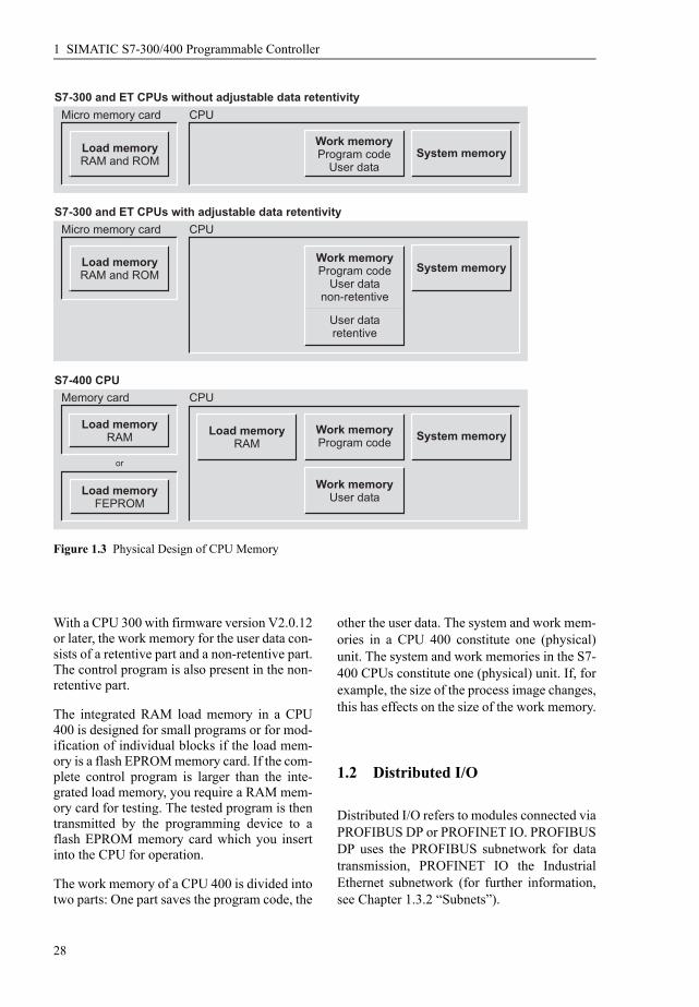