ber prediction using exit charts for bicm with iterative decoding
TRANSCRIPT
IEEE COMMUNICATIONS LETTERS, VOL. 10, NO. 1, JANUARY 2006 49
BER Prediction using EXIT Charts forBICM with Iterative Decoding
Thorsten Clevorn, Susanne Godtmann, and Peter Vary
Abstract— A method for the prediction of bit-error rates(BER) of bit-interleaved coded modulation systems with iterativedecoding (BICM-ID) is presented, which is based solely upon theextrinsic information transfer (EXIT) chart and avoids extensiveBER simulations. Comparisons show an accurate prediction, evenfor low BERs down to 10−6. Furthermore, an easy procedure toobtain the optimum rotation angle for a signal constellation setin conjunction with IQ Interleaving is described. Both methodscan be applied to all types of channels.
Index Terms— BICM-ID, EXIT chart, BER, IQ interleaving.
I. INTRODUCTION
B IT-INTERLEAVED coded modulation with iterative de-coding (BICM-ID) [1] is a bandwidth efficient coded
modulation scheme which increases the time-diversity andconsequently is especially suited for Rayleigh fading channels.At the receiver the channel decoder and the demodulatorexchange extrinsic information in a Turbo process. SuchTurbo processes are often analyzed using extrinsic informationtransfer (EXIT) charts [2]. In [2] also a method is presented topredict the BER of a Turbo code system using only the EXITchart.
We extend this method to BICM-ID. This extension isnot straightforward, because for BICM-ID no information onthe data bits is available in the EXIT chart itself. Using theproposed method extensive BER simulations can be avoided.Comparisons with such simulations demonstrate that the BERscan be very accurately predicted in the whole Eb/N0-range,even for much lower BERs (down to 10−6) than in [2].
Additionally, using elements of this algorithm we demon-strate how to obtain the optimum rotation angle in case ofIQ interleaving for a signal constellation set. These methodsare both applicable to all types of channels for which therespective EXIT chart can be generated and are not limited tothe exemplary Rayleigh fading channel.
II. THE BICM-ID SYSTEM
The considered BICM-ID transmitter encodes a block ofdata bits u by a standard non-systematic feed-forward convo-lutional encoder. The resulting encoded bits x are permuted bya pseudo-random bit-interleaver π to x and grouped consecu-tively into bit patterns xt =[x(1)
t , ... x(I)t ], where x
(i)t denotes
Manuscript received June 28, 2005. The associate editor coordinating thereview of this letter and approving it for publication was Prof. Giorgio Taricco.This work was supported by the DFG (Deutsche Forschungsgemeinschaft).
The authors have been with the Institute of Communication Sys-tems and Data Processing, RWTH Aachen University, Germany (e-mail:[email protected]). S. Godtmann is now with the Institute forIntegrated Signal Processing Systems, RWTH Aachen University, Germany.
Digital Object Identifier 10.1109/LCOMM.2006.01012.
Decoder Demod.π
π-1
P [ext,enc]CD (x) P [ext,enc]
CD (x)
P [ext]DM (x) P [ext]
DM (x)
P [ext,dec]CD (u)
u z
fromchannel
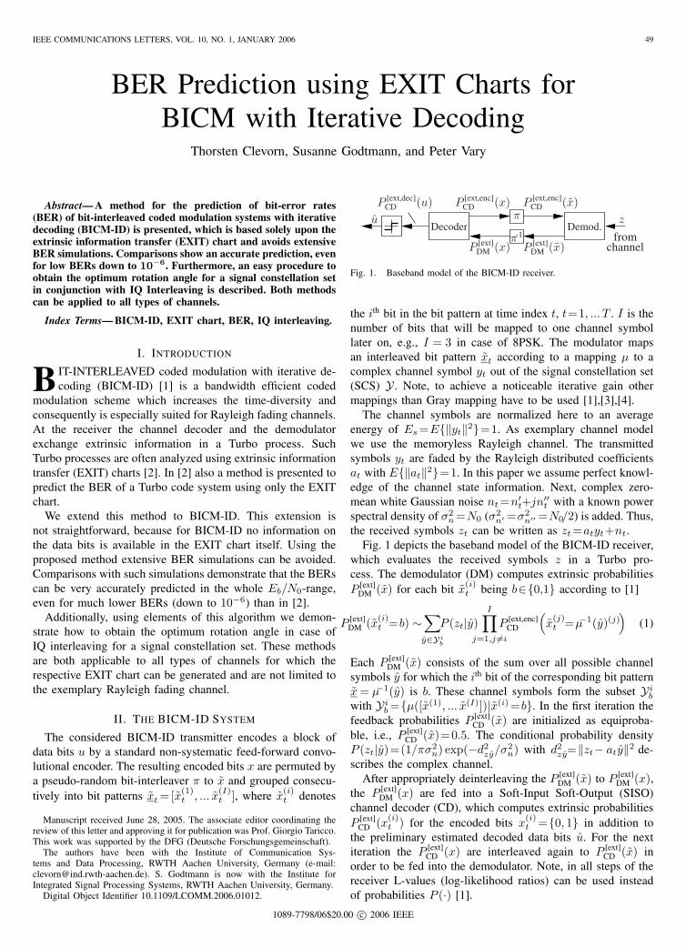
Fig. 1. Baseband model of the BICM-ID receiver.
the ith bit in the bit pattern at time index t, t=1, ... T . I is thenumber of bits that will be mapped to one channel symbollater on, e.g., I = 3 in case of 8PSK. The modulator mapsan interleaved bit pattern xt according to a mapping µ to acomplex channel symbol yt out of the signal constellation set(SCS) Y . Note, to achieve a noticeable iterative gain othermappings than Gray mapping have to be used [1],[3],[4].
The channel symbols are normalized here to an averageenergy of Es =E{‖yt‖2}=1. As exemplary channel modelwe use the memoryless Rayleigh channel. The transmittedsymbols yt are faded by the Rayleigh distributed coefficientsat with E{‖at‖2}=1. In this paper we assume perfect knowl-edge of the channel state information. Next, complex zero-mean white Gaussian noise nt =n′
t+jn′′t with a known power
spectral density of σ2n =N0 (σ2
n′ =σ2n′′ =N0/2) is added. Thus,
the received symbols zt can be written as zt =atyt+nt.Fig. 1 depicts the baseband model of the BICM-ID receiver,
which evaluates the received symbols z in a Turbo pro-cess. The demodulator (DM) computes extrinsic probabilitiesP [ext]
DM (x) for each bit x(i)t being b∈{0,1} according to [1]
P [ext]DM (x(i)
t =b) ∼∑y∈Yi
b
P (zt|y)I∏
j=1,j �=i
P [ext,enc]CD
(x
(j)t =µ−1(y)(j)
)(1)
Each P [ext]DM (x) consists of the sum over all possible channel
symbols y for which the ith bit of the corresponding bit patternx = µ−1(y) is b. These channel symbols form the subset Yi
b
with Yib ={µ([x(1), ... x(I)])|x(i) =b}. In the first iteration the
feedback probabilities P [ext]CD (x) are initialized as equiproba-
ble, i.e., P [ext]CD (x)=0.5. The conditional probability density
P (zt|y)=(1/πσ2n) exp(−d2
zy/σ2n) with d2
zy=‖zt− aty‖2 de-scribes the complex channel.
After appropriately deinterleaving the P [ext]DM (x) to P [ext]
DM (x),the P [ext]
DM (x) are fed into a Soft-Input Soft-Output (SISO)channel decoder (CD), which computes extrinsic probabilitiesP [ext]
CD (x(i)t ) for the encoded bits x
(i)t ={0, 1} in addition to
the preliminary estimated decoded data bits u. For the nextiteration the P [ext]
CD (x) are interleaved again to P [ext]CD (x) in
order to be fed into the demodulator. Note, in all steps of thereceiver L-values (log-likelihood ratios) can be used insteadof probabilities P (·) [1].
1089-7798/06$20.00 c© 2006 IEEE

50 IEEE COMMUNICATIONS LETTERS, VOL. 10, NO. 1, JANUARY 2006
0 10
1
I [apri]DM , I [ext,enc]
CD [bit]
I[ext
]D
M,I[a
pri,e
nc]
CD
[bit]
Demodulator, Eb/N0 =0 dB
Demodulator, Eb/N0 =8 dB
Channel Decoder, {15, 17}8
BE
RP
b
10−1
10−2
10−310−410−510−6
cmp. Fig. 3
Fig. 2. EXIT characteristics for 8PSK-SP, Rayleigh channel.
0 10
1
0 10
10
0 1010−6
100
I [apri,enc]CD [bit] I [ext,dec]
CD [bit] σ2u
I[ext
,dec
]C
D[b
it]
σ2 u
BE
RP
b
Fig.
2
Fig. 4
Fig. 3. The steps for BER prediction (“•” example for 8PSK-SP at 4 dB).
III. BER PREDICTION USING EXIT CHARTS
EXIT charts [2],[5] are a powerful tool to analyze andoptimize the convergence behavior of iterative systems utiliz-ing the Turbo principle, i.e., systems exchanging and refiningextrinsic information. The capabilities of the components, inour case the demodulator (DM) and the channel decoder (CD),are analyzed separately. The extrinsic mutual information I [ext]
obtained by each component for a certain a priori mutualinformation I [apri] is determined. Both, I [ext] and I [apri], arecalculated on the basis of the actual bits, e.g., x, and theavailable information, extrinsic or a priori, for these bits. Asbasis for this calculation usually histograms of the respectiveL-values, e.g., L[ext]
DM of P [ext]DM for I [ext]
DM , are used. For theEXIT characteristics the a priori L-values are simulated asuncorrelated Gaussian distributed, with variance σ2
A and meanµA =σ2
A/2. The convergence behavior of BICM-ID has beenstudied, e.g., in [6],[7],[8].
In this letter, we extend the capabilities of the EXIT chartto the prediction of BERs Pb, as proposed for Turbo codesin [2] and, e.g., applied to iterative MIMO receivers in [5].However, the adaptation is not straightforward because in con-trast to [2] the mutual information on the data bits u, I [ext,dec]
CD ,is not used in the EXIT chart, but the mutual informationon the encoded bits x, I [ext,enc]
CD . In Fig. 2 the EXIT char-acteristics for an 8-state, rate-1/2, feed-forward convolutionalcode with generator polynomials {15, 17}8 and for 8PSK-SP(set-partitioning) mapping [1] are depicted. The EXIT char-acteristic of the demodulator, I [ext]
DM =f(I [apri]DM ), depends on
the channel quality, while the channel decoder characteristic,I [ext,enc]
CD =f(I [apri,enc]CD ), is independent of Eb/N0, because the
only input for the decoder is P [ext]DM (x). Thus, also I [ext,dec]
CD , andconsequently the BER Pb of the data bits u, depend solelyon I [apri,enc]
CD =I [ext]DM . The points “◦” mark the intersections
0 1 2 3 4 5 6 7 810
−6
10−5
10−4
10−3
10−2
10−1
100
8PSK-SP
8PSK-SSPsimulated
estim. I [ext]DM (I [apri]
DM )estim. I [ext]
DM (I [apri]DM =1)
Eb/N0 [dB]
BE
RP
b
cmp. Fig. 3
Fig. 4. Simulated and predicted BERs, 8-state conv. code, Rayleigh channel.
between the EXIT characteristics of demodulator and channeldecoder and the points “�” mark the EXIT characteristics ofthe demodulator at I [apri]
DM =1 bit (cmp. Fig. 4).With the additionally measured EXIT characteristic
I [ext,dec]CD =f(I [apri,enc]
CD ) for the decoded output of the decoder(Fig. 3, left plot) and the assumption of a Gaussian distributeddecoder output L[ext]
CD (u) with variance σ2u [2] we can stepwise
calculate the BER. As example in Fig. 3 we use 8PSK-SPmapping at Eb/N0 =4 dB (point “•” in Figs. 2 and 4).• Using the respective EXIT characteristic we can obtainI [ext,dec]
CD for a given I [apri,enc]CD =I [ext]
DM (Fig. 3, left plot).• With the inverse relation σu≈J−1(I [ext,dec]
CD ) (this functioncannot be expressed in closed form; for details see [2]) thevariance σ2
u is computed (Fig. 3, center plot).
• Finally, the BER Pb is calculated as Pb = 12 erfc
(σ2
u
2√
2
)(Fig. 3, right plot)On the right side of Fig. 2 a second axis for the BER is
added. As already discussed before, the BER is independentof I [ext,enc]
CD =I [apri]DM . Thus, in contrast to the systems in [2],[5],
for the considered BICM-ID system the curves of constantBER are simply horizontal lines (not depicted in Fig. 2).
In Fig. 4 the predicted BERs are compared with simulatedBERs for the 8-state convolutional code of Fig. 2 and 8PSK-SP and 8PSK-SSP (semi-set-partitioning) mappings [1]. Theblock size is 12000 data bits per frame and 30 iterations areperformed at the receiver. For infinite block size, a perfectinterleaver, and a sufficient number of iterations the decodingtrajectory should reach the intersection of the channel decodercharacteristic and the demodulator characteristic in the EXITchart. In Fig. 2 these points are marked by “◦” for thedepicted characteristics. As visible in Fig. 4 the correspondingestimated BERs (dashed curve “◦”) quite well match thesimulated BERs (solid curve) in the whole depicted Eb/N0-range. The waterfall-region as well as the error floor are accu-rately predicted, providing a simple design tool for BICM-IDsystems for all channel conditions.
A key feature for the analysis of BICM-ID is the errorfloor [1],[3],[4]. In [7],[4] it was shown that the error floorcan be analyzed using the EXIT chart. For the analysis ofthe error floor, error-free feedback (EFF) for the demodulatoris assumed (for details see, e.g., [1]). This EFF is similarto perfect a priori knowledge, i.e., I [apri]
DM = 1 bit. Thus, theasymptotic behavior, i.e., the error floor, can be analyzed using

CLEVORN et al.: BER PREDICTION USING EXIT CHARTS FOR BICM WITH ITERATIVE DECODING 51
θ
000
101010
111
100
001110
011= x
x(1)(Bit 1) x(2)(Bit 2) x(3)(Bit 3)
y
Fig. 5. 8PSK-SSP mapping [1] with EFF decision distances.
the right axis of the EXIT chart [7],[4]. Consequently, forestimation of the error floor of the BER we have to use thedemodulator characteristics at I [apri]
DM = 1 bit (points marked“�” in Fig. 2). Furthermore, a nice feature is that these pointswith I [apri]
DM = 1 bit can also be evaluated numerically, seee.g. [7], instead of using extensive Monte-Carlo simulations.The respective curve for the BER in Fig. 4 (dashed curvemarked “�”) shows that also the asymptotic behavior alone isvery well predicted. Comparing Figs. 2 and 4 reveals that theBER for 8PSK-SP reaches the error floor at Eb/N0 ≈ 4 dB,corresponding to only I [apri]
DM ≈ 0.85 bit, indicating that (inthis case) already for I [apri]
DM > 0.85 bit the feedback can beconsidered as quasi error-free.
The curves for 8PSK-SSP (see Fig. 5) in Fig. 4 demonstratethat the proposed BER estimation is accurate for BERs downto at least 10−6. In contrast, the BER prediction for Turbocodes in [2] is only reliable for BERs down to 10−3.
IV. OPTIMUM ROTATION ANGLES FOR IQ INTERLEAVING
Using elements of the BER prediction method proposedin Section III we will in the following present a simplemethod for obtaining the optimum rotation angle θ for amapping, when the signal space diversity [9] is exploited byIQ interleaving [10] for a Rayleigh channel. With separateinterleaving of the in-phase (I) and quadrature (Q) componentthe performance is not anymore invariant to a rotation ofthe SCS [10]. Although IQ interleaving is especially suitedfor QAM SCSs, for consistency we consider exemplarily the8PSK-SSP mapping [1] (Fig. 5) used before.
The error floor performance of BICM-ID is directly relatedto the decision distances for the EFF case, shown for 8PSK-SSP in Fig. 5 (right side). With IQ interleaving these distancesshall not lie vertically or horizontally, but rather have largeI and Q components. Examining the error floor we plotI [ext]
DM (I [apri]DM =1) for different rotation angles θ in Fig. 6. Note
that, e.g., for the optimization of θ for non-iterative BICMyou would use I [ext]
DM (I [apri]DM =0). As visible the highest I [ext]
DMis obtained for θ=22.5◦, the lowest for θ=67.5◦. Intuitively,with θ = 22.5◦ all distances for bits 1 and 2 have non-zeroI and Q components and the distances for bit 3 even featureidentical I and Q components resulting in a good performance.In contrast, for θ = 67.5◦ the decision distances of bit 3 areparallel to the I or Q axis (I or Q component is zero), withbits 1 and 2 being principally similar to the θ=22.5◦ case.
With I [apri,enc]CD =I [ext]
DM the differences in required Eb/N0 fora certain I [ext]
DM are directly related to the BER as shown inFig. 7. The mentioned Eb/N0 correspond to a BER of 10−6,i.e., I [ext]
DM ≈0.904 in Fig. 6, for the respective rotation angle θ.
0.87
0.88
0.89
0.9
0.91
0.920.93
SCS rotation angle θ [◦]
I[ext
]D
M(I
[apr
i]D
M=
1)
0 90
Eb/N0 =6.8 dB
Eb/N0 =6.3 dBEb/N0 =5.9 dB
Fig. 6. I[ext]DM (I[apri]
DM =1) vs. rotation angle θ for 8PSK-SSP mapping.
4 5 6 7 10
−6
10−5
10−4
simulated
estim. I [ext]DM (I [apri]
DM =1)
Eb/N0 [dB]
BE
RP
b
θ=67.5◦
θ=22.5◦θ=0◦
5.9 dB6.3 dB
6.8 dB
Fig. 7. Simulated and predicted BERs, 8-state conv. code, 8PSK-SSP,Rayleigh channel with IQ interleaving.
V. CONCLUSION
We presented a method to predict the BER of a BICM-IDsystem based solely on the EXIT characteristics of channeldecoder and demodulator. Extensive BER simulations can beavoided. Comparisons show that the BERs of the waterfalland the error floor region are accurately estimated, evenfor relatively low BERs such as 10−6. The error floor isalready reached for an a priori mutual information lower than1 bit. Furthermore, a procedure based on the EXIT chart toobtain the optimum rotation angle for an IQ interleaved signalconstellation set is described. Both presented methods can beused in conjunction with all types of channels.
REFERENCES
[1] X. Li, A. Chindapol, and J. A. Ritcey, “Bit-interleaved coded modulationwith iterative decoding and 8PSK signaling,” IEEE Trans. Commun.,vol. 50, pp. 1250–1257, Aug. 2002.
[2] S. ten Brink, “Convergence behavior of iteratively decoded parallelconcatenated codes,” IEEE Trans. Commun., vol. 49, pp. 1727–1737,Oct. 2001.
[3] F. Schreckenbach, N. Gortz, J. Hagenauer, and G. Bauch, “Optimizationof symbol mappings for bit-interleaved coded modulation with iterativedecoding,” IEEE Commun. Lett., vol. 7, pp. 593–595, Dec. 2003.
[4] T. Clevorn, S. Godtmann, and P. Vary, “PSK versus QAM for iterativedecoding of bit-interleaved coded modulation,” in Proc. IEEE Globe-com, vol. 1, Dec. 2004, pp. 341–345.
[5] E. Biglieri, A. Nordio, and G. Taricco, “Iterative receivers for codedMIMO signaling,” J. Wireless Commun. and Mobile Computing, vol. 4,pp. 697–710, Nov. 2004.
[6] Y. Huang and J. A. Ritcey, “EXIT chart analysis of BICM-ID withimperfect channel state information,” IEEE Commun. Lett., vol. 7, pp.434–436, Sept. 2003.
[7] T. Clevorn, S. Godtmann, and P. Vary, “EXIT chart analysis of non-regular signal constellation sets for BICM-ID,” in Proc. ISITA 2004,Oct. 2004, pp. 21–26.
[8] J. Tan and G. L. Stuber, “Analysis and design of symbol mappers foriteratively decoded BICM,” IEEE Trans. Wireless Commun., vol. 3, pp.662–672, Mar. 2005.
[9] J. Boutros and E. Viterbo, “Signal space diversity: a power- andbandwidth-efficient diversity technique for the Rayleigh fading channel,”IEEE Trans. Inform. Theory, vol. 44, pp. 1453–1467, July 1998.
[10] A. Chindapol and J. A. Ritcey, “Design, analysis, and performanceevaluation for BICM-ID with square QAM constellations in Rayleighfading channels,” IEEE J. Select. Areas Commun., vol. 19, pp. 944–957,May 2001.