benefits of using new shipping industry collision risk ... · practices used in the shipping...
TRANSCRIPT

Health and Safety Executive
Assessment of the benefits to the offshore industry from new technology and operating practices used in the shipping industry for managing collision risk
Prepared by Anatec UK Limited for the Health and Safety Executive 2007
RR592 Research Report
Health and Safety Executive
Assessment of the benefits to the offshore industry from new technology and operating practices used in the shipping industry for managing collision risk
Anatec UK Limited 16 Ward Way Witchford Ely Cambs CB6 2JR
There is a continuing duty for duty holders to manage risk and to keep possible risk reduction measures under review giving account to changing circumstances, advances in technology, new knowledge and information. Good practice may change over time; new technology may make a higher standard reasonably practicable. Continuous improvement leads to repeated challenge of existing measures and approaches to safety management.
In pursuit of this, this report provides an overview of the latest technologies being employed within the maritime industry which have the potential to benefit the oil and gas industry in support of their commitment to the management of collision risk. The study builds upon the previous work carried out by the HSE and Oil and Gas UK.
This report and the work it describes were funded by the Health and Safety Executive (HSE). Its contents, including any opinions and/or conclusions expressed, are those of the authors alone and do not necessarily reflect HSE policy.
HSE Books

© Crown copyright 2007
First published 2007
All rights reserved. No part of this publication may bereproduced, stored in a retrieval system, or transmitted inany form or by any means (electronic, mechanical,photocopying, recording or otherwise) without the priorwritten permission of the copyright owner.
Applications for reproduction should be made in writing to:Licensing Division, Her Majesty’s Stationery Office,St Clements House, 216 Colegate, Norwich NR3 1BQor by email to hmsolicensing@cabinetoffice.x.gsi.gov.uk
ii

CONTENTS
1 INTRODUCTION .................................................................................................................1
1.1 BACKGROUND .....................................................................................................................11.2 OBJECTIVES .........................................................................................................................11.3 ABBREVIATIONS ..................................................................................................................1
2 CHANGES IN OFFSHORE PRACTICES .......................................................................4
2.1 INTRODUCTION ....................................................................................................................42.2 ERRV SHARING ..................................................................................................................42.3 USE OF MULTI-ROLE VESSELS...........................................................................................52.4 USE OF REMOTE NUIS ........................................................................................................5
3 SYSTEMS OVERVIEW ......................................................................................................7
4 RADAR....................................................................................................................................8
4.1 INTRODUCTION ....................................................................................................................84.2 RANGE OF DETECTION ........................................................................................................84.3 CARRIAGE REQUIREMENTS ................................................................................................94.4 MARINE RADAR PERFORMANCE STANDARDS ............................................................... 104.5 RADAR PLOTTING/TRACKING AIDS ................................................................................ 134.6 RADAR DISPLAYS............................................................................................................. 164.7 SOFTWARE SYSTEMS........................................................................................................ 164.8 CONCLUSIONS................................................................................................................... 16
5 UNIVERSAL AUTOMATIC IDENTIFICATION SYSTEM (AIS) .......................... 19
5.1 INTRODUCTION ................................................................................................................. 195.2 CARRIAGE REQUIREMENTS ............................................................................................. 195.3 OPERATIONAL REQUIREMENTS ....................................................................................... 205.4 AIS DATA OVERVIEW...................................................................................................... 205.5 TRANSMISSION OF DATA ................................................................................................. 215.6 RANGE............................................................................................................................... 225.7 DISPLAY OF AIS DATA .................................................................................................... 245.8 OTHER USEFUL AIS MESSAGE TYPES............................................................................ 265.9 LIMITATIONS OF AIS AND CAUTIONARY NOTES ON ITS USE........................................ 285.10 CONCLUSIONS .............................................................................................................. 29
6 AID TO NAVIGATION INFORMATION SERVICE (ANIS) ................................... 31
6.1 INTRODUCTION ................................................................................................................. 316.2 SYSTEM OVERVIEW.......................................................................................................... 316.3 CONCLUSION..................................................................................................................... 32
7 ECDIS................................................................................................................................... 33
7.1 INTRODUCTION ................................................................................................................. 337.2 SYSTEM OVERVIEW.......................................................................................................... 337.3 ELECTRONIC CHARTS IN ECDIS ..................................................................................... 347.4 CHART COVERAGE ........................................................................................................... 357.5 CONCLUSIONS................................................................................................................... 35
8 VOYAGE DATA RECORDERS (INCLUDING S-VDRS) ......................................... 37
8.1 INTRODUCTION ................................................................................................................. 37
iii
8.2 SYSTEM OVERVIEW.......................................................................................................... 388.3 POTENTIAL USE IN OIL AND GAS INDUSTRY.................................................................. 42
9 E-NAVIGATION................................................................................................................ 44
9.1 INTRODUCTION ................................................................................................................. 449.2 SYSTEM OVERVIEW.......................................................................................................... 449.3 CONCLUSIONS................................................................................................................... 46
10 LONG RANGE IDENTIFICATION AND TRACKING (LRIT) .............................. 47
10.1 INTRODUCTION ............................................................................................................ 4710.2 SYSTEM OVERVIEW ..................................................................................................... 4710.3 CONCLUSIONS .............................................................................................................. 48
11 IMO ROUTEING MEASURES....................................................................................... 49
11.1 INTRODUCTION ............................................................................................................ 4911.2 STANDARD INDUSTRY PRACTICE ............................................................................... 4911.3 OTHER IMO MEASURES.............................................................................................. 5111.4 CONCLUSIONS .............................................................................................................. 53
12 FISHING ACTIVITY SYSTEMS.................................................................................... 56
12.1 KIS-UKCS ................................................................................................................... 5612.2 KIS-CA......................................................................................................................... 5612.3 FISHSAFE .................................................................................................................... 5712.4 SATELLITE MONITORING............................................................................................. 5812.5 CONCLUSIONS .............................................................................................................. 5912.6 GMDSS ........................................................................................................................ 6012.7 SPECIAL USE VHF CHANNELS ................................................................................... 6112.8 NAVIGATIONAL WARNINGS........................................................................................ 6212.9 M-NOTICES .................................................................................................................. 6312.10 AIS-SART.................................................................................................................... 6412.11 ELECTRONIC CHARTS .................................................................................................. 6412.12 HYBRID SYSTEMS ........................................................................................................ 6512.13 MARITIME DATA CENTRE (WWW.MARITIMEDATA.CO.UK) ...................................... 6612.14 THE MARINE SAFETY FORUM..................................................................................... 66
13 CLOSING DISCUSSION.................................................................................................. 68
14 REFERENCES.................................................................................................................... 69
APPENDIX A: FIELD TRIALS – RADAR AND AIS COMPARISON.
iv

1 INTRODUCTION
1.1 BACKGROUND There is a continuing duty for duty holders to manage risk and to keep possible risk reduction measures under review giving account to changing circumstances, advances in technology, new knowledge and information. Good practice may change over time; new technology may make a higher standard reasonably practicable. Continuous improvement leads to repeated challenge of existing measures and approaches to safety management.
In pursuit of this, this report provides an overview of the latest technologies being employed within the maritime industry which have the potential to benefit the oil and gas industry in support of their commitment to the management of collision risk. The study builds upon the previous work carried out by the HSE and Oil & Gas UK (Refs. i and ii).
The timing of the work was driven by two key factors:
• The need to consider the recent step-change in marine technology which has considerable potential to assist the offshore industry in the management of passing and infield collision risk.
• The need to further consider the novel practices being applied offshore in relation to the use of multipurpose vessels and ERRV sharing, to ensure the effectiveness of the collision risk management strategy is not jeopardised.
It is noted that this report does not cover all possible measures available to industry but highlights several recent developments that have occurred in the maritime sector. It is the responsibility of the Operator to ensure an appropriate level of attention is given to this process bearing in mind that the energy generated by infield and passing vessel collisions are often significantly higher than the capacity of an offshore installation.
1.2 OBJECTIVES The main objectives of the document are to:
• Discuss the effects of recent offshore practices such as the use of multipurpose vessels and shared standby vessels. The aim will be to identify the affect of these practices on collision risk management.
• Provide an overview of the new technologies that have been introduced to the maritime industry which may offer benefit to the offshore industry in terms of collision risk management.
Both passing and infield vessel risk management are considered within the project.
1.3 ABBREVIATIONS AIS - Automatic Identification System ALARP - As Low As Reasonably Practicable ANIS - Aids to Navigation Information Service ARPA - Automatic Radar Plotting Aid ATA - Automatic Tracking Aid AtoN - Aid to Navigation
1

COLREGS - International Regulations for Avoiding Collisions at Sea CPA - Closest Point of Approach CRM - Collision Risk Management CRT - Cathode Ray Tube DC - Daughter Craft Defra - Department for Environment, Food and Rural Affairs DSC - Digital Selective Calling ECDIS - Electronic Chart Display and Information System EER - Evacuation, Escape and Rescue ENC - Electronic Navigational Charts EPIRB - Emergency Position-Indicating Radio Beacon ERRV - Emergency Response and Rescue Vessel EPA - Electronic Plotting Aid FRC - Fast Rescue Craft GIS - Geographical Information System GMDSS - Global Maritime Distress and Safety System GPS - Global Positioning System GT - Gross Tonnes GTA - Group Training Association HSE - Health and Safety Executive Hz - Hertz IHO - International Hydrographic Organisation IMO - International Maritime Organisation KIS - Kingfisher Information Services KIS-CA - Kingfisher Information Services – Cable Awareness LCD - Liquid Crystal Display LRIT - Long Range Identification and Tracking MCA - Maritime and Coastguard Agency MEH - Marine Electronic Highway MJ - Mega Joules MKD - Minimum Keyboard and Display MIN - Marine Information Notice MGN - Marine Guidance Notice MSF - Marine Safety Forum MSN - Marine Shipping Notice NAVTEX - NAVigational TEXt NFFO - National Federation of Fishermen's Organisations nm - Nautical Miles NUI - Normally Unattended Installation PFEER - Prevention of Fire and Explosion, and Emergency Response QRA - Quantitative Risk Assessment RADAR - Radio Detection and Ranging RNC - Raster Navigational Charts SFF - Scottish Fishermen's Federation SOLAS - Safety of Life at Sea SOTDMA - Self-Organising Time Division Multiple Access S-VDR - Simplified Voyage Data Recorder TCPA - Time to Closest Point of Approach UKCS - United Kingdom Continental Shelf VDR - Voyage Data Recorders VHF - Very High Frequency
2

VMS - Vessel Monitoring System VTS - Vessel Traffic Services WWNWS - World-Wide Navigational Warning Service
3

2 CHANGES IN OFFSHORE PRACTICES
2.1 INTRODUCTION This section provides background information on the current and emerging practices offshore which are of relevance when considering the maritime technology required for ensuring effective collision risk management.
2.2 ERRV SHARING It has recently become common practice for an ERRV to support multiple installations. The arrangements can vary widely but two generic examples are provided below.
Example 1: A permanently manned installation with a number of satellite NUIs. The ERRV normally attends the manned installation alone but when a satellite is visited the ERRV provides a safety function to both installations. This may involve moving to a position midway between the two manned installations or using a Daughter Craft (DC) or Fast Rescue Craft (FRC) in proximity to one with the mother craft at the other.
Example 2: Two permanently manned installations share an ERRV. During normal operations the ERRV may have an operating envelope normally holding position between the two installations (taking into account weather, current, etc.). When specific operations are being carried out (e.g., overside work or helicopter flights) the ERRV may offset itself so as to attend one installation more closely. Again, DC or FRC may be used in this scenario.
A key requirement of any ERRV sharing arrangement in the UK is to meet the requirement to have effective arrangements for recovery and rescue as laid out in Regulation 17 of the Offshore Installations (Prevention of Fire and Explosion, and Emergency Response) Regulations 1995. This includes effective arrangements for:
a) Recovery of persons following their evacuation or escape from the installation; and b) Rescue of persons near the installation; and c) Taking of such persons to a place of safety
The accompanying guidance states that there are many circumstances where only a suitable vessel standing by will provide effective arrangements and in these circumstances such a vessel will need to be provided.
The vessel should be maintained in a position from which it can be best used for the recovery and rescue functions required of it, taking account of nature and time of work activities - such as overside working - being carried out. Such vessels may be shared between installations provided that it does not compromise the object of securing a good prospect of recovery and rescue.
Additionally, sharing an ERRV between installations can affect the effectiveness of the collision risk management strategy. The key factors in relation to this are:
• Assuring Detection capability: Timely detection of the threat, i.e., identifying an approaching vessel on a collision course with an installation in sufficient time to both attempt control measures (discussed below) and perform a controlled evacuation of the installation should it prove necessary.
4

• Provision of adequate time to Control a collision scenario: This is the provision of time to ensure reasonable attempt can be made to control / avert the threat, such as communication with the vessel or alerting it by other means such as light and sound signals when at close-quarters. In most instances these actions are to be taken prior to making the decision for a controlled evacuation if this is necessary.
Both detection and control capability can be influenced by the technology being adopted at the field and care needs to be taken to ensure it is selected correctly and in line with the requirements of the installation(s) or field(s). For example, traditionally, detection has been carried out by radar and visual lookout but new marine technology means that other measures may now be available such as AIS, which are explored later in the report. Similarly, controlling action covers warning the vessel about the installation which traditionally meant communicating via VHF radio but again recent developments in maritime technology mean that Digital Selective Calling (DSC) and other methods may be appropriate.
2.3 USE OF MULTI-ROLE VESSELS There has been a trend in recent years on the UKCS to replace old ERRV with upgraded vessels that perform transfer operations (cargo and bulk) in addition to the traditional standby vessel role.
Again in this instance there is a need to ensure that the requirement to have effective arrangements for recovery and rescue as laid out in Regulation 17 of the Offshore Installations (Prevention of Fire and Explosion, and Emergency Response) Regulations 1995. This includes effective arrangements for can be met.
In addition collision risk management issues associated need consideration as using an ERRV in the supply vessel role can introduce potential problems in detection of a collision threat and being able to respond to the collision scenario as laid out in procedure. For example, positioning the vessel alongside an installation can result in radar shadows that could mask an approaching vessel.
It is noted that where offtake tankers are used at fields, ERRV are often used in mooring operations and to prevent fish-tailing, which again can lead to shadow sectors on radar or result in the unavailability of the vessel to respond to a collision scenario as attended, be this physically or through bridge manning levels which may be limited in this circumstance.
2.4 USE OF REMOTE NUIS As discussed in Section 2.2, performance standards for sharing an ERRV are often defined in terms of recovery and rescue of personnel when a normally unattended installation (NUI) or satellite is manned.
However, these installations are still exposed to risk of passing ship collision at other times when the ERRV may not be in such close proximity. Also there are NUIs in the UKCS which are remote from manned installations and ERRVs and therefore currently have no prospect of detection / control of a collision threat the vast majority of the time.
Whilst there may be no threat to POB, a ship collision could still have major consequences in terms of loss of life (ship’s crew), as well as financial and business costs, such as repair, production downtime, adverse publicity, etc.
5

Advancements in maritime technology may offer economical solutions to this situation whereby remote installations at marginal fields can have traffic monitoring and some form of intervention if a collision threat is detected.
6

3 SYSTEMS OVERVIEW
The following systems are considered within this work:
Table 3.1 Systems considered within study System Section Number
Radar 4 AIS 5 Aids to Navigation Information Services 6 ECDIS 7 Voyage Data Recorder 8 E-Navigation 9 Long Range Identification and Tracking 10 IMO Routeing Measures 11 Fishing Activity Systems 12 Additional 13
In addition to this, the appendix to this report provides details of an AIS/Radar performance trial that was recently carried out by Anatec UK Ltd.
7

4 RADAR
4.1 INTRODUCTION Radar is an abbreviation of Radio Detection and Ranging. Radar’s effectiveness as a navigational aid is based on the detection of backscatter of transmitted energy from an object (the echo-effect). The targets (objects) are displayed in such a way that their bearing and range is continuously available.
Due to radar being dependent on the physical backscatter of microwaves it is limited to line of sight and performance deteriorates when there are obstructions between the antenna and the target object.
Figure 4.1 Typical radar unit
4.2 RANGE OF DETECTION The theoretical range (line of sight) for radar is calculated as follows:
( )ettantenna hhRange arg23.2 +•=
where the heights, h, are measured in metres and the range given in nautical miles.
Using this equation it is possible to determine the theoretical capability of a radar system, e.g., an antenna at 15m height (50 foot) would theoretically be able to detect a 15m high vessel at a range of 17nm. It is noted that this is the theoretical range of detection and will be influenced by a number of factors that are highlighted later within this section.
8

0
5
10
15
20
25
0 1 2 3 4 5 6 7 8 9 10 11 12 13 14 15 16 17 18 19 20 21 22 23 24 25
Height of Target (m)
Theo
retic
al D
etec
tion
Ran
ge (n
m)
antenna height = 10 mantenna height = 15 mantenna height = 20 m
Figure 4.2 Radar (Theoretical Range of Detection)
4.3 CARRIAGE REQUIREMENTS Radar is the primary electronic device used by shipping to determine and display the range and bearing of radar transponders and of other surface craft, obstructions, buoys, shorelines and navigational marks to assist in navigation and in collision avoidance.
It is also the primary electronic device used by the oil and gas industry to detect vessels passing in proximity to their fields to assist in the management of collision risk. This tends to be either through radar on the ERRV or the installation, although in some instances there is prospect for shore based surveillance.
When adopting radar for platform collision risk management it is important to recognise that this is not the primary function that radar was designed for - which is to assist the Master in preserving the safety of the vessel, its crew, any passengers and cargo. As a result there are limitations associated with using radar for collision risk management that need careful consideration.
In addition, as the collision risk requirements at each field will vary depending on the impact strength of the platform, the shipping characteristics (speeds and size) and the warning time required on the installation(s) so will the performance requirement being placed upon the radar.
This requires careful selection and it will not always be the case that the radar equipment available on an ERRV will be suited to the way in which an Operator wishes to manage collision risk at a platform/field. Field specific assessments/trials are needed to assess and demonstrating whether equipment is suitably specified and fit for purpose in all conditions likely to be experienced.
9

- -- -- -- -- -- -- -
4.4 MARINE RADAR PERFORMANCE STANDARDS To develop upon the previous section, it is useful to consider the performance of radar. Overall there are four major components which need consideration;
• Antennae • Transmitter • Receiver • Display
As with any system, radar can be set up in a variety of configurations and from components of varying specifications. As a result, the performance of radar varies considerably in terms of maximum and minimum range of detection, target discrimination, etc.
Typical factors that influence radar performance include:
Signal Reception Signal-to-noise ratio
Receiver Bandwidth Receiver Sensitivity
Pulse shape Pulse compression Power Scan Rate Beam Width Pulse Repetition Frequency Antennae Gain Carrier Frequency Radar Cross Section of Target Antennae aperture
It is not within the scope of this work to consider each of these in detail but rather to highlight that when radar is being used for collision risk management care needs to be taken to ensure that the main components and the overall system are specified correctly.
IMO Resolution MSC.64(67) contains a number of minimum performance standards applicable to civil marine radar. These are laid out as minimum operational requirements under normal propagation conditions, when the radar antenna is mounted at a height of 15 metres above sea level.
The following table summarises some of the key radar performance standards in relation to collision risk management.
Table 4.1 Radar performance requirements Coastal Range Performance
At 20 nautical miles when the ground rises to 60 m. At 7 nautical miles when the ground rises to 6 m.
Surface Object Range At 7 nautical miles a ship of 5,000 gross tonnage, whatever her aspect. Performance At 3 nautical miles a small vessel of 10m in length.
At 2 nautical miles an object such as a navigational buoy having an effective echoing area of approximately 10m2.
Range Measurement Error not exceeding 1% of the maximum range of the scale in use, or 30m, whichever is greater
Bearing Measurement Maximum error of not greater that ±1°. Range Discrimination On the 1.5 nautical miles range the radar must be capable of displaying two
small similar targets at a range of 0.75 – 1.5 nautical miles and on the same
10

–
bearing when separated by no more than 40m. Bearing Discrimination On the 1.5 nautical miles range the radar must be capable of displaying two
small similar targets at a range of 0.75 1.5 nautical miles when at the same range and when separated by no more than 2.5° in bearing.
Note: There is also a requirement that the performance of the equipment should continue to be met when the ship is rolling or pitching up to 10°.
The resolution also states that a suitable means also needs to be provided for the suppression of unwanted echoes from sea clutter, rain and other forms of precipitation, clouds, sandstorms and from other radars. These need to have the ability to be adjusted manually although automatic anti-clutter controls may be fitted provided that they can be switched off.
Overall the operational requirement when the radar antenna is mounted at a height of 15 m above sea level is that the equipment should, even in the presence of sea clutter, give a clear indication of a standard reflector up to 3.5 nautical miles.
As can be seen, these standards do not assure detection capability of surface objects beyond 7 nm and the above performance capability is only assured for roll and pitch of a vessel up to 10°. In sea clutter conditions the performance of the radar is only assured to a range of 3.5nm.
This falls far short of what is generally required offshore and the oil and gas industry places reliance on radar significantly beyond this level of performance for ship monitoring. Operators need to consider this when developing collision risk management strategy for their fields.
Particular attention needs to be placed on monitoring vessels at moderate to long range from the radar scanner as radar performance is not assured at these ranges. This assessment needs to give account to the influence of weather conditions on detection performance for each of the vessel types and sizes that has potential to threaten the structural integrity of the platform, again highlighting the importance of offshore trials.
On 6 December 2004 the IMO adopted Resolution MSC.192(79) “Revised Performance Standards for Radar Equipment” which require radar to provide the integration and display of radar video, target tracking information, positional data derived from own ship’s position (EPFS) and geo referenced data.
Under this resolution it is stated that the integration and display of AIS information should be provided to complement radar. The capability of displaying selected parts of Electronic Navigation Charts and other vector chart information may also be provided to aid navigation and for position monitoring.
This resolution states that the radar, combined with other sensor or reported information (e.g. AIS), should improve the safety of navigation by assisting in the efficient navigation of ships and protection of the environment by satisfying the following functional requirements:
• in coastal navigation and harbour approaches, by giving a clear indication of land and other fixed hazards;
• as a means to provide an enhanced traffic image and improved situation awareness;
11

• in a ship-to-ship mode for aiding collision avoidance of both detected and reported hazards;
• in the detection of small floating and fixed hazards, for collision avoidance and the safety of own ship; and
• in the detection of floating and fixed aids to navigation.
Details of the revised performance standards are provided in Table 4.2, which indicates that detection range is now increased to 11nm for vessels of around 5,000 gross tonnes.
Table 4.2 Revised radar performance requirements
Target Description Target Height above Sea (m)
Detection Range in NM
X-Band S-Band
Shorelines Shorelines Shorelines SOLAS ships (>5,000 gross tonnage) SOLAS ships (>500 gross tonnage) Small vessel with radar reflector IMO Performance Standards1 meeting Navigation buoy with corner reflector Typical Navigation buoy Small vessel of length 10 m with no radar reflector
Rising to 60 Rising to 6 Rising to 3 10 5.0 4.0
3.5 3.5 2.0
20 8 6 11 8 5.0
4.9 4.6 3.4
20 8 6 11 8 3.7
3.6 3.0 3.0
The resolution recommends for Governments to ensure that radar equipment installed on or after 1 July 2008 conform to performance standards not inferior to those set out in the Annex to the resolution.
The revised standards should apply to all shipborne radar installations, used in any configuration, mandated by the 1974 SOLAS Convention, as amended. Some slight variation applies depending on ships gross tonnage.
Table 4.3 Radar requirements per ship gross tonnage Size of ship/craft <500 gt 500 to <10kgt,
HSC<10kgt All ships/craft =>10,000 gt
Min operational display area diameter 180 mm 250 mm 320 mm
Minimum display area 195 x 195 mm 270 x 270 mm 340 x 340 mm
Auto acquisition of targets - - Yes
Minimum acquired radar target capacity 20 30 40
Minimum activated AIS target capacity 20 30 40
Minimum sleeping AIS target capacity 100 150 200
Trial Manoeuvre - - Yes
12
Other performance standards remained unchanged.
Although overall the new standards are more stringent it is still apparent that the oil and gas industry tends to rely on radar well outwith these criteria for collision risk management. It is the responsibility of the Operator to demonstrate that the equipment being used is fit for purpose.
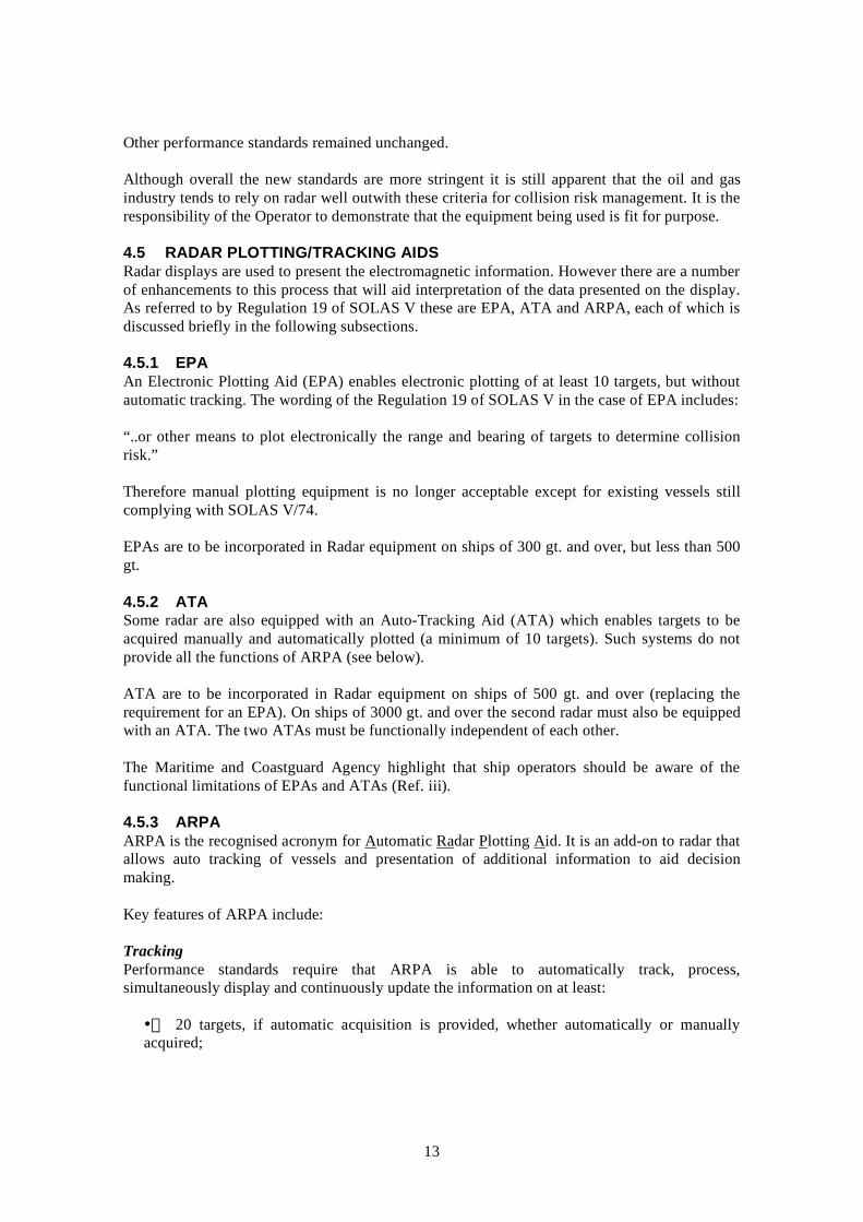
4.5 RADAR PLOTTING/TRACKING AIDS Radar displays are used to present the electromagnetic information. However there are a number of enhancements to this process that will aid interpretation of the data presented on the display. As referred to by Regulation 19 of SOLAS V these are EPA, ATA and ARPA, each of which is discussed briefly in the following subsections.
4.5.1 EPA An Electronic Plotting Aid (EPA) enables electronic plotting of at least 10 targets, but without automatic tracking. The wording of the Regulation 19 of SOLAS V in the case of EPA includes:
“..or other means to plot electronically the range and bearing of targets to determine collision risk.”
Therefore manual plotting equipment is no longer acceptable except for existing vessels still complying with SOLAS V/74.
EPAs are to be incorporated in Radar equipment on ships of 300 gt. and over, but less than 500 gt.
4.5.2 ATA Some radar are also equipped with an Auto-Tracking Aid (ATA) which enables targets to be acquired manually and automatically plotted (a minimum of 10 targets). Such systems do not provide all the functions of ARPA (see below).
ATA are to be incorporated in Radar equipment on ships of 500 gt. and over (replacing the requirement for an EPA). On ships of 3000 gt. and over the second radar must also be equipped with an ATA. The two ATAs must be functionally independent of each other.
The Maritime and Coastguard Agency highlight that ship operators should be aware of the functional limitations of EPAs and ATAs (Ref. iii).
4.5.3 ARPA ARPA is the recognised acronym for Automatic Radar Plotting Aid. It is an add-on to radar that allows auto tracking of vessels and presentation of additional information to aid decision making.
Key features of ARPA include:
Tracking Performance standards require that ARPA is able to automatically track, process, simultaneously display and continuously update the information on at least:
• 20 targets, if automatic acquisition is provided, whether automatically or manually acquired;
13
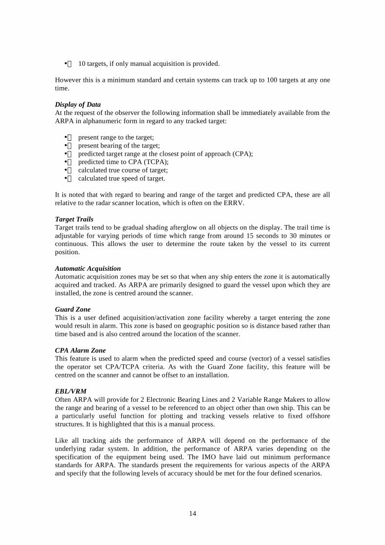
• 10 targets, if only manual acquisition is provided.
However this is a minimum standard and certain systems can track up to 100 targets at any one time.
Display of Data At the request of the observer the following information shall be immediately available from the ARPA in alphanumeric form in regard to any tracked target:
• present range to the target; • present bearing of the target; • predicted target range at the closest point of approach (CPA); • predicted time to CPA (TCPA); • calculated true course of target; • calculated true speed of target.
It is noted that with regard to bearing and range of the target and predicted CPA, these are all relative to the radar scanner location, which is often on the ERRV.
Target Trails Target trails tend to be gradual shading afterglow on all objects on the display. The trail time is adjustable for varying periods of time which range from around 15 seconds to 30 minutes or continuous. This allows the user to determine the route taken by the vessel to its current position.
Automatic Acquisition Automatic acquisition zones may be set so that when any ship enters the zone it is automatically acquired and tracked. As ARPA are primarily designed to guard the vessel upon which they are installed, the zone is centred around the scanner.
Guard Zone This is a user defined acquisition/activation zone facility whereby a target entering the zone would result in alarm. This zone is based on geographic position so is distance based rather than time based and is also centred around the location of the scanner.
CPA Alarm Zone This feature is used to alarm when the predicted speed and course (vector) of a vessel satisfies the operator set CPA/TCPA criteria. As with the Guard Zone facility, this feature will be centred on the scanner and cannot be offset to an installation.
EBL/VRM Often ARPA will provide for 2 Electronic Bearing Lines and 2 Variable Range Makers to allow the range and bearing of a vessel to be referenced to an object other than own ship. This can be a particularly useful function for plotting and tracking vessels relative to fixed offshore structures. It is highlighted that this is a manual process.
Like all tracking aids the performance of ARPA will depend on the performance of the underlying radar system. In addition, the performance of ARPA varies depending on the specification of the equipment being used. The IMO have laid out minimum performance standards for ARPA. The standards present the requirements for various aspects of the ARPA and specify that the following levels of accuracy should be met for the four defined scenarios.
14

--
-- --
Table 4.4 Accuracy values (95 per cent probability values) within one minute of steady state tracking
Scenario 1 Relative Course (°) Relative Speed (kts) CPA (nm)
1 11 2.8 1.6 2 7 0.6 3 14 2.2 1.8 4 15 1.5 2
Table 4.5 Accuracy values (95 per cent probability values) within three minute of steady state tracking
Scenario 1 Relative
Course (°) Relative
Speed (kts) CPA (nm) TCPA (min)
True Course (°)
True Speed (kts)
1 3 0.8 0.5 1 7.4 1.2 2 2.3 0.3 2.8 0.8 3 4.4 0.9 0.7 1 3.3 1 4 4.6 0.8 0.7 1 2.6 1.2
From the above it can be seen that there is uncertainty regarding the information displayed on the ARPA that requires consideration when establishing collision risk management procedures as vessels may appear to be passing an installation safely due to tracking inaccuracy when in reality it is on a collision course. Therefore when reliance is being placed on remote tracking at medium to long range consideration needs to be given to the level of uncertainty associated with the targets position. This is for all radar based systems.
Where uncertainty levels reach a significant magnitude, e.g. remote monitoring of shipping, there is the prospect to overcome this by the incorporation of a secondary scanner in closer proximity to the remote site. Alternatively AIS can also be used to improve positional accuracy although not all vessels can be tracked using AIS (see Section 5 for further details).
Again these are minimum guidelines and more sophisticated equipment is available to provide enhanced performance so careful selection is required and there is significant benefit to be had by undertaking field trials to ensure there is an accurate understanding of how the system is performing at the field and its overall capability.
1 Scenario description
Scenario 1 Scenario 2 Scenario 3 Scenario 4 Own ship course 000° 000° 000° 000°
Own ship speed (kts) 10 10 5 25
Target range (nm) 8 1 8 8
Bearing of target 000° 000° 045° 045°
Relative course of target 180° 090° 225° 225°
Relative speed of target (kts) 20 10 20 20
15

4.6 RADAR DISPLAYS There are a wide variety of radar displays which will influence the ease in which information being displayed on the radar can be interpreted.
There are two basic display types;
• CRT (Cathode Ray Tube) • LCD (Liquid Crystal Display)
Each type has different advantages that need to be considered when choosing radar.
A CRT has high contrast in normal to low light, allowing for bright and clear targets to be shown on the display. Bright sunlight will tend to make the CRT display fade and overall CRT radars work best in an environment that is either covered or out of direct sunlight.
LCD units are more compact and usually waterproof. The viewable area of a LCD is actually larger than its CRT counterpart, because it has a flat screen surface. The contrast on a LCD display is increased when it is back-lit or front-lit.
4.7 SOFTWARE SYSTEMS There are a variety of software systems that will enhance the capability of radar/ARPA and reduce some of the limitations that exist in terms of collision risk management for offshore installations.
As with radar these systems need to be carefully specified but in general they can provide significant benefit in terms of allowing:
• Alarms to be offset around several installations • Electronic charts to be used (Section 12.11) • Multiple input sources, e.g. multiple scanners or AIS devices.
Care needs to be taken to assess the performance of equipment through trials and not through the marketing material that often supports software systems.
4.8 CONCLUSIONS Radar is one of the primary electronic aids to navigation used by shipping and performance standards are set by the IMO. These systems are designed with the primary function of protecting the vessel, crew, passengers and cargo and therefore when using them for other purposes their capability and limitations require careful consideration.
Radar does not receive information from passing vessels in a positive manner, i.e. it is up to the radar and user to find the ship. Other systems such as AIS offer more reliable means of detection although only for vessels equipped with operational AIS.
The minimum performance standards for radar and ARPA, etc are set significantly lower than is often being relied upon to monitoring shipping around offshore oil and gas platforms, so careful selection of equipment is required. It may be that the equipment on an ERRV does not provide the performance that is required at the field. This needs to be identified prior to the vessel arriving at the field. Software based systems that rely on a feed from radar, e.g. VTS, REWS may also suffer from low radar performance so require assessment.
16

In terms of management of collision risk at offshore fields the main factors that require consideration are the range of detection, accuracy of information provided by the system and ability to monitor shipping to offset structures (not own ships).
Where long range detection is being relied upon close consideration needs to be given to the location of the scanner and the power of the radar. Within this process it should be borne in mind that sea state and environmental conditions, such as rain, snow, etc., will result in further degradation of the radar performance.
The accuracy of a radar system diminishes the further the target is from the scanner which means these systems are not always suitable for long range monitoring, e.g., guarding of remote assets. Remote scanners can offer improvement in this situation or this can be achieved through the use of AIS (see Section 5).
A number of add-ons to radar are available to assist in the interpretation of the data on the display. The main system used on larger vessels is ARPA which tracks vessels being displayed on the radar. These systems vary in capability with the minimum requirement being the capability to track 10 vessels. More advanced systems can track up to 100 vessels so careful consideration is required to ensure the system adopted is fit for purpose.
There are further limitations associated with ARPA which mainly relate to its auto acquiring and alarming capability as this is centred around the scanner (which is often on the ERRV). When this becomes critical (more so in when multiple installation are being guarded) software systems can be adopted to improve the ARPA capability.
Trials are the best means of demonstrating that performance of the equipment/systems being used is fit for purpose, especially as the way in which the equipment is being used is not in line with its design function, which is to protect the vessel upon which it is installed.
Radar relies on a physical process and is therefore is affected by shadow/blind sectors. This requires consideration if the ERRV is acting as a multi-role vessel and is required to work alongside a platform for extended periods.
There are a number of display systems for radar which have the potential to aid the user when interpreting a situation. In cases where additional workload is being placed on the user such as guarding multiple assets, the display of information requires more careful consideration to ensure the user does no suffer for overload.
Much of the marketing information on radar and associated equipment provides an overview of how they perform. Experience has shown that these do not form a good basis for equipment selection and this should be based on actual experience. Trials are a useful way of obtaining the information on the system performance to ensure it functions as expected and in the conditions likely to be experienced at the field.
Competence and training in the use of radar and associated tracking equipment requires careful consideration. If monitoring is being carried out on the platform an appropriate level of competence is required as those involved may otherwise have limited maritime experience. There will be sound maritime experience on the ERRV in terms of using radar and ARPA, beyond this, e.g., more complicated user interfaces with guard zone options, may require further training.
17

As radar coverage is one of the primary means of collision hazard detection consideration should be given to the operational impact of radar failure or reduced performance of radar due to weather conditions, or other reasons.
AIS can provide a suitable means of overcoming a number of limitations of radar. Full details of AIS are presented in Section 5.
18

5 UNIVERSAL AUTOMATIC IDENTIFICATION SYSTEM (AIS)
5.1 INTRODUCTION Universal AIS (or AIS, as it is commonly known) is an emerging ship and shore based broadcasting system, operating in the VHF maritime band. Two frequency channels have been designated for AIS use worldwide, on the high seas and in all other areas, unless other frequencies are designated on a regional basis for AIS purposes. The two designated frequencies are:
• AIS 1 (Channel 87B, 161.975 MHz) • AIS 2 (Channel 88B, 162.025 MHz)
An AIS station is basically a VHF radio transceiver capable of sending ship information such as identity, position, course, speed, length, ship type and cargo information etc., to other ships and suitable receivers. The information from an operational AIS unit is transmitted continuously and automatically without of the need for action by the ship’s crew so operates independent of manning levels.
Figure 5.1 Typical AIS equipment
5.2 CARRIAGE REQUIREMENTS Regulation 19 of SOLAS Chapter V - Carriage requirements for shipborne navigational systems and equipment - sets out navigational equipment to be carried on board ships, according to ship type. In 2000, IMO adopted a new requirement (as part of a revised new chapter V) for ships to carry automatic identification systems (AIS). This requires AIS to be fitted aboard all ships of 300 gross tonnes and upwards engaged on international voyages, cargo ships of 500 gross tonnes and upwards not engaged on international voyages and passenger ships irrespective of size built on or after 1 July 2002. It also applies to ships engaged on international voyages constructed before 1 July 2002, according to the following timetable:
• passenger ships, not later than 1 July 2003; • tankers, not later than the first survey for safety equipment on or after 1 July 2003; • ships, other than passenger ships and tankers, of 50,000 gross tonnage and upwards, not later than 1 July 2004.
19

An amendment adopted by the Diplomatic Conference on Maritime Security in December 2002 states that ships, other than passenger ships and tankers, of 300 gross tonnage and upwards but less than 50,000 gross tonnage, will be required to fit AIS not later than the first safety equipment survey after 1 July 2004 or by 31 December 2004, whichever occurs earlier.
5.3 OPERATIONAL REQUIREMENTS Ships fitted with AIS are required to maintain AIS in operation at all times except where international agreements, rules or standards provide for the protection of navigational information.
If the master believes that the continual operation of AIS might compromise the safety or security of his/her ship, the AIS may be switched off. This might be the case in sea areas where pirates and armed robbers are known to operate. Actions of this nature should always be recorded in the ship’s logbook together with the reason for doing so. The master should however restart the AIS as soon as the source of danger has disappeared.
5.4 AIS DATA OVERVIEW Class A AIS is mandatory under Regulation 19 of SOLAS Chapter V. The information transmitted by a ships using Class A is of three different types:
• fixed or static information, which is entered into the AIS on installation and need only be changed if the ship changes its name or undergoes a major conversion from one ship type to another;
• dynamic information, which, apart from ‘Navigational status’ information, is automatically updated from the ship sensors connected to AIS; and
• voyage-related information, which might need to be manually entered and updated during the voyage.
The following lists present the data provided via Class A AIS.
Table 5.1 AIS information Static Dynamic Voyage related
MMSI Position (Lat/Long) Draught IMO Number Time Hazardous Cargo (type) Call Sign Course over ground Destination Name Speed over ground ETA Length and Beam Heading Route Plan Type of Ship Navigational Status Type of Nav Sensor Rate of Turn
Class B AIS was specified as a much less expensive, limited range and limited feature sub-set of the original Class A with the view to be used by smaller non-SOLAS vessels. Class B carriage is not mandatory but it is felt that there will be a gradual take up of this equipment once the benefits are better understood. The reporting rate for Class B is less than a Class A (e.g. every 30 sec. when under 14 knots, as opposed to every 10 sec. for Class A). Other features are as follows:
20

• Does not transmit the vessel’s IMO number or call sign • Does not transmit ETA or destination • Does not transmit navigational status • Is only required to receive, not transmit, text safety messages • Is only required to receive, not transmit, application identifiers (binary messages) • Does not transmit rate of turn information • Does not transmit maximum present static draught
However Class B will transmit the ships position, along with MMSI number, vessel name, type of vessel and its dimensions.
5.5 TRANSMISSION OF DATA The operation of AIS depends on the Self Organizing Time Division Multiple Access (SOTDMA) data communication technology. Under SOTDMA each minute of time is divided into 2250 time slots or 26.67 ms each time slot. With a transmission speed of 9.6 kbps this translates into 256 Bits/time-slot, sufficient for one AIS report.
In order to make more efficient use of the bandwidth available, vessels which are anchored or are moving slowly transmit less frequently than those that are moving faster or are manoeuvring. The update rate of fast manoeuvring vessels is similar to that of conventional marine radar. Table 5.2 provides a summary of the transmission rates of AIS.
Table 5.2 Transmission rates of AIS class A Type of Ship Reporting Interval
Ship at anchor 3 min Ship 0-14 knots 12 sec Ship 0-14 knots and changing course 4 sec Ship 14-23 knots 6 sec Ship 14-23 knots and changing course 2 sec Ship >23 knots 3 sec Ship >23 knots and changing course 2 sec
The reporting rates for Class B are less frequent as indicated in Table 5.3.
Table 5.3 Reporting intervals for class B shipborne equipment Class B shipborne mobile equipment not moving faster than 2 knots 3 min
Class B shipborne mobile equipment moving 2-14 knots 30 sec
Class B shipborne mobile equipment moving 14-23 knots 15 sec
Class B shipborne mobile equipment moving > 23 knots 5 sec
Table 5.4 e(
Reporting intervals for other quipment Search and rescue aircraft airborne mobile 10 sec
21

equipment) Aids to navigation 3 min AIS base station (1) 10 sec
(1) The base station rate should increase to once per 3 1/3 s after the station detects that one or more stations are synchronizing to the base station
Overall the required ship reporting capacity according to the IMO performance standard amounts to a minimum of 2000 time slots per minute, though the actual system (two frequencies) provides 4500 time slots per minute.
The SOTDMA broadcast mode allows the system to be overloaded by 400 to 500% through sharing of slots, and still provide nearly 100% through put for ships closer than 8 to 10 NM to each other in a ship to ship mode. In the event of system overload, targets further away will be subject to drop-out, in order to give preference to nearer targets that are a primary concern to ship operators.
In practice, the capacity of the system is nearly unlimited, allowing for a great number of ships to be accommodated at the same time.
Figure 5.2 Principles of SOTDMA
5.6 RANGE The system coverage range is similar to other VHF applications, essentially depending on the height of the antenna. Its propagation is slightly better than that of radar, due to the longer wavelength, so it is possible to “see” around bends and behind islands if the land masses are not too high. A typical value to be expected at sea is nominally 20 nautical miles from a vessel, which extends significantly for a more elevated antennae installation. With the help of repeater stations, the coverage for both ship and VTS stations can be improved considerably.
When operational and in range, the performance of AIS in terms of target pick up is improved over radar. AIS operates through the broadcast and receipt of information over VHF compared
22

to radar which relies on detection of backscatter of transmitted energy from an object (the echo-effect) and relies more heavily on tuning and the ability to distinguish echoes from clutter. This is a particular concern with radar when being used to track smaller vessels at range or in poor weather conditions.
Data from trials carried out by Anatec UK Ltd which provides a comparison of the two systems are available within the Appendix to this report. Some summary figures are presented below:
5.3 )Figure Area of coverage (radar
Figure 5.4 Area of coverage (AIS)
23

0%
10%
20%
30%
40%
50%
60%
70%
80%
90%
100%
0 5 10 15 20 25 30 35 40 45 50 55 60
Detection Range (nm)
% V
esse
ls
AIS Average
Radar Average
Figure 5.5 Range of detection profile (ARPA vs. AIS)
5.7 DISPLAY OF AIS DATA
5.7.1 Types of display The initial carriage requirements do not specify shipboard display for use by the mariner, except for the minimal, basic numerical identification data. A typical minimum keyboard and display (MKD) is presented below:
Figure 5.6 MKD display
Alternative systems to the MKD display are the graphical displays that are often provided with an AIS transponder as shown in Figure 5.7.
24

Figure 5.7 Types of AIS display
AIS data can also be fed into AIS tracking software. These systems are similar to those used to complement radar as discussed under Section 4 and can be set up to display passing vessels on raster or ENC chart overlays as presented in Figure 5.8.
Figure 5.8 AIS software display
It is also possible to have integrated ARPA and AIS systems such that the AIS and radar data can be displayed on the radar display simultaneously to allow for improved decision making. Considerable research has been carried out to ensure that displays do not become over cluttered with information and confusion to the watchkeeper.
25

5.7.2 AIS symbols The IMO agreed on guidelines for the presentation of navigation-related symbols in 2004 (SN/Circ.236). The aim of this is to promote the display of navigation-related information on all shipborne navigational equipment in a consistent and uniform manner. The guide provides detail on the symbols recommended for the target types presented in Table 5.5.
Table 5.5 AIS symbol description
Sleeping target A sleeping target indicates only the presence of a vessel equipped with AIS in a certain location. No additional information is presented until activated, thus avoiding information overload.
Activated target
If the user wants to know more about a vessel’s motion, he has simply to activate the target (sleeping), so that the display shows immediately: - a vector (speed and course over ground), - the heading, and - ROT indication to display actually initiated course changes.
Selected target
If the user wants detailed information on a target (activated or sleeping), he may select it. Then the data received, as well as the calculated CPA and TCPA values, will be shown in an alpha-numeric window. The special navigation status will also be indicated in the alpha numeric data field and not together with the target directly
Dangerous target If an AIS target (activated or not) is calculated to pass pre-set CPA and TCPA limits, it will be classified and displayed as a dangerous target and an alarm will be given.
Lost target If a signal of any AIS target at a distance of less than a preset value is not received, a lost target symbol will appear at the latest position and an alarm will be given.
5.8 OTHER USEFUL AIS MESSAGE TYPES AIS is not solely used for tracking vessels and also has the capability to perform a wide range of other functions as are discussed in the following subsections.
5.8.1 Message 6, 7 and 8 binary messaging The IMO (International Maritime Organisation) has developed seven binary messages for worldwide use. These messages include:
• Meteorological and Hydrological Data • Number of Persons on Board • Extended Ship Static and Voyage related Data (Air draught) • Fairway Closed • Tidal Window • Dangerous Cargo Indication • Pseudo AIS targets (re-broadcasting of VTS radar targets)
The ITU has defined two additional messages for worldwide use:
• Ship’s Route Plan (containing the next Waypoints of a ship) • Recommended Ship’s Route (Recommendation of waypoints from a VTS for a vessel)
The use of Binary Messages is optional and they may be generated manually or automatically. Since the use of binary messages places an additional load on the VHF data link, care must be
26

taken not to impair the main functions of AIS for ship identification and tracking. In this regard it is recommended that longer binary messages may adversely impact the VHF data link and should be avoided.
Some of the information contained within a Meteorological and Hydrological binary message includes:
Latitude Longitude Wind gust direction Wave period Date and time Horizontal visibility Wave direction Average wind speed Surface current speed Swell height Wind gust Surface current direction Swell direction Wind direction Significant wave height Sea state
The breakdown of binary messaging is as follows:
• Message 6 is an address binary message which is sent to a specific MMSI address.
• Message 7 is a binary acknowledgement of a received addressed binary message.
• Message 8 is a binary broadcast message which is not addressed and does not require an acknowledgment.
5.8.2 Message 9: Standard SAR aircraft position report This message provides a standard position report for aircraft involved in SAR operations. The default reporting interval for this message should be 10 seconds.
5.8.3 Message 12, 13 and 14: Safety related message Short safety-related messages are fixed or free format text messages addressed either to a specified MMSI (addressed) or all ships in the area (broadcast). It is recommended that their content be relevant to the safety of navigation, e.g., an iceberg sighted or a buoy not on station. Messages should be kept as short as possible. The system allows up to 158 characters per message but the shorter the message the more easily it will find free space for transmission.
At present these messages are not further regulated, to keep all possibilities open.
• Class A shipborne mobile equipment has to be capable of receiving and transmitting short safety related messages containing important navigational or important meteorological warning.
• Class B shipborne mobile equipment has to be capable of receiving short safety related messages
The breakdown of safety related messaging is as follows:
• Message 12 is an address safety message which is sent to a specific MMSI address.
• Message 13 is a safety acknowledgement of a received addressed safety message.
27

• Message 14 is a safety broadcast message which is not addressed and does not require an acknowledgment.
5.8.4 Message 21: Aids-to-navigation report This message is to be used by a station mounted on an aid-to-navigation. It may provide a positive identification of the aid along with an accurate position and additional information such as actual tidal height or local weather; details which cannot be charted due to their dynamic and unpredictable nature. AIS transmitters on AtoN will be charted using the large circle and abbreviation ‘AIS’, in magenta.
5.9 LIMITATIONS OF AIS AND CAUTIONARY NOTES ON ITS USE
5.9.1 IMO guidance The IMO has provided guidelines for the use of Shipborne AIS within (Resolution A.917(22). Within the document attention is also placed on the inherent limitation of AIS which require careful consideration. They are listed below:
• The officer of the watch (OOW) should always be aware that other ships, in particular leisure craft, fishing boats and warships, and some coastal shore stations including Vessel Traffic Service (VTS) centres, might not be fitted with AIS.
• The OOW should always be aware that other ships fitted with AIS as a mandatory carriage requirement might switch off AIS under certain circumstances by professional judgement of the master (see Section 5.3).
• In other words, the information given by the AIS may not be a complete picture of the situation around the ship.
• The users must be aware that transmission of erroneous information implies a risk to other ships as well as their own. The users remain responsible for all information entered into the system and the information added by the sensors.
• The accuracy of AIS information received is only as good as the accuracy of the AIS information transmitted.
• The OOW should be aware that poorly configured or calibrated ship sensors (position, speed and heading sensors) might lead to incorrect information being transmitted. Incorrect information about one ship displayed on the bridge of another could be dangerously confusing.
• If no sensor is installed or if the sensor (e.g. the gyro) fails to provide data, the AIS automatically transmits the "not available" data value. However, the built-in integrity check cannot validate the contents of the data processed by the AIS.
• It would not be prudent for the OOW to assume that the information received from other ships is of a comparable quality and accuracy to that which might be available on own ship.
The IMO guidelines also provide a summary of the following cautionary points to consider with using AIS for collision avoidance situations:
28

• AIS is an additional source of navigational information. It does not replace, but supports, navigational systems such as radar target-tracking and VTS; and
• the use of AIS does not negate the responsibility of the OOW to comply at all times with the Collision Regulations.
The IMO guidelines also state that the user should not rely on AIS as the sole information system, but should make use of all safety-relevant information available and that the use of AIS on board ships is not intended to have any special impact on the composition of the navigational watch, which should continue to be determined in accordance with the STCW Convention.
5.9.2 MCA guidance - MGN 324 (M+F) The MCA has issued this MGN entitled “Radio: Operational Guidance on the Use of VHF Radio and Automatic Identification Systems (AIS) at Sea”. Within the MGN it is noted that mariners should use AIS information with caution noting the following important points:
a.) Collision avoidance must be carried out in strict compliance with the COLREGs. There is no provision in the COLREGs for use of AIS information therefore decisions should be taken based primarily on visual and/or radar information.
b.) The use of VHF to discuss action to take between approaching ships is fraught with danger and still discouraged. (See MGN 167 – Dangers in the use of VHF in collision avoidance.) The MCA’s view is that identification of a target by AIS does not remove the danger. Decisions on collision avoidance should be made strictly according to the COLREGs.
c.) Not all ships will be fitted with AIS, particularly small craft and fishing boats. Other floating objects which may give a radar echo will not be detected by AIS.
d.) AIS positions are derived from the target’s GNSS position. This may not coincide with the radar target.
e.) Faulty data input to AIS could lead to incorrect or misleading information being displayed on other vessels. Mariners should remember that information derived from radar plots relies solely upon the data measured by the own-ship’s radar and provides an accurate measurement of the target’s relative course and speed, which is the most important factor in deciding upon action to avoid collision. Existing ships of less than 500 GT which are not required to fit a gyro compass are unlikely to transmit heading information.
f.) A future development of AIS is the ability to provide “pseudo” navigation marks by enabling coastal authorities to provide an AIS symbol on the display in any position. Mariners should bear in mind that this ability could lead to the appearance of “spurious” AIS targets and therefore take particular care when an AIS target is not complemented by a radar target. It should be noted though that AIS will sometimes be able to detect targets which are in a radar shadow area.
5.10 CONCLUSIONS AIS has a significant role to play in the management of collision risk at offshore oil and gas installations.
At the time of preparing this report it was identified that most offshore installations do not broadcast an AIS signature. By placing an AIS Transceiver on a platform or drilling rig the
29

structure will then broadcast its position to any ships in the area that are equipped with AIS. This will provide details on the installation name and its position. Additionally, having AIS installed on the platform or rig will give the potential to broadcast and receive any of the other AIS messages as outlined in Section 5.8.1. These include:
• Binary Messages • SAR Position Reports • Safety Related Messaged • Aids to Navigation Report
Note: When setting up AIS on an installation it is useful to give account to the IMO Guidelines for the Installation of Shipborne Automatic Identification System (AIS) as some of the key issue remain pertinent to an installation (Ref: SN/Circ.227).
AIS operates through the broadcast and receipt of information over VHF and as a result the exchange of information will take place when the transceivers are in range of one another (approximately 20nm at ships mast height). This is different to the operation of radar which relies on detection of backscatter of transmitted energy from an object (the echo-effect) and relies more heavily on tuning and the ability to distinguish echoes from clutter. This is a particular concern with radar when being used to track smaller vessels at range or in poor weather.
AIS tracking will only identify vessels carrying AIS transceivers that are operational (working and switched on). This should be the vast majority of shipping >300GT as highlighted under Sections 5.2 and 5.3, however certain vessels will not be tracked, e.g. fishing and recreational craft, warships, etc. The impact of this in terms of collision risk management requires careful consideration.
AIS tracking offers considerable improvement when compared to radar based systems in terms of range and accuracy. In addition AIS does not suffer from blind sectors to the same extent experienced by radar, and is not influenced by weather conditions or the target size to any great extent.
Although both radar and AIS provide the basic information required for collision risk management, i.e. target presence, course and speed, AIS provides more information that can lead to improved control and response, e.g., name of vessel, size of vessel, etc.
Due to the substantial amount of data that can be gathered using AIS it can be used in a variety of ways to aid risk management. Attention should be placed on ensuring best use is made of this technology to provide a:
• better understanding the shipping hazards in an area • means of contacting regular shipping • basis for developing Hazard Management Plans including Alarm Zone Settings (CPA versus TCPA) • means of demonstrating infield vessel procedure compliance
30

6 AID TO NAVIGATION INFORMATION SERVICE (ANIS)
6.1 INTRODUCTION The objective of the Aids to Navigation Information Service (ANIS) is to provide automatically real-time information to ships on the status of aids to navigation that are critical for the safety of navigation and the protection of the marine environment.
6.2 SYSTEM OVERVIEW The concept is that an ECDIS (see Section 7) or other suitable Electronic Display used on board the ship for navigational purposes can indicate when knowledge is received that the operational status of an AtoN has changed from the information provided on charts of the area, or when aids to navigation are being used to mark uncharted wrecks or other new hazards so that mariners have up to date navigational information on the area in which they are navigating. It is possible for this to be achieved virtually in some cases whereby there is no physical AtoN and its position and supporting information is only broadcast in AIS or similar.
Under this scheme it is indicated that as shipborne display techniques develop, the method of presentation should enable mariners to assimilate the total real-time situation of charted information, AtoNs and shipping in their vicinity rapidly and unambiguously in all weather conditions. This data can include real time information on currents and tides if these are being recorded electronically.
In addition, Aid to Navigation Authorities will be able to initiate immediate warnings to shipping through ANIS if there is:
• a shipping casualty or other uncharted hazard in the local area; or, • a malfunction or defect to an Aid to Navigation is reported by any other means.
Five different types of ANIS messages are proposed, respectively containing information on the following situations:
Message type 1 - A drifting floating aid and its current position;Message type 2 - A new or uncharted hazard;Message type 3 - The malfunction of an AtoN;Message type 4 - A message to cancel any Message Type 1, 2 or 3 that is no longerapplicable;Message type 5 - A communication check message.
The messages will be connected directly to the ship’s “Operational Display” through the interface standards set out in IEC Publication 1162 – “Digital Interface – Navigation and Radio communication equipment on board ships”.
In the first instance the “Operational Display” is expected to be an Electronic Display and Information System (ECDIS). However developments are currently taking place on “Head up” chart displays and on 3-D displays that are expected to be able to reproduce the view seen from the bridge of a ship in clear weather conditions in the form of a “virtual reality display”.
31
The attention of ships’ navigating officers will be drawn to a change of the status of an AtoN by the appropriate chart symbol flashing or by a similar form of attention getting and the details of the malfunction will be available on selection. In the case of a new wreck or other uncharted hazard, the attention will be drawn to the situation by the area concerned being highlighted in a manner similar to the change of status of an AtoN and the details will be available on selection.
Message Types 1 and 3 are transmitted continuously at intervals of 2 to 3 minutes until the hazard, disruption or malfunction is removed or rectified. Information from these messages should stop being displayed on receipt of an appropriate Message type 4.
Message Type 2 is transmitted continuously at intervals of 2-3 minutes until either the hazard is removed or a period of six weeks has elapsed since the hazard was charted by the local Charting Authority. Information from these messages should stop being displayed on receipt of an appropriate Message type 4.
Message Type 5 is transmitted at intervals of 30 minutes when no messages type 1, 2, or 3 are being transmitted. Messages of this type should not be shown on the display but information about the latest communication check should be available on selection.
When no malfunction or defect has been identified or reported and there are no uncharted hazards in the area concerned, ANIS will broadcast a communication check message at intervals of 30 minutes.
6.3 CONCLUSION Surface offshore oil and gas activities will be marked by AtoN to ensure they are “visible” to the maritime community. The ANIS system has the potential to provide contingency to industry should there be a failure in a navigational aid by automatically ensuring ships in the local area are aware of the change in navigational aid status.
ANIS has the potential to allow a virtual buoy or emergency mark to appear to ships via their onboard display in the same way as a normal aid to navigation would appear but without the physical need for it to be installed. This would allow the immediate marking of new hazards rather than waiting for a ship to deploy a buoy and in the longer term, the need for some buoys may be withdrawn altogether as they can be suitably replaced in a virtual manner.
This may also allow for “virtual” cardinal marks to be located around offshore installations where there are high densities of shipping passing close to the location. Virtual markings may also offer particular benefit to temporary operations such as drilling where the costs associated with physical navigational aids can be high in relative terms.
32
7 ECDIS
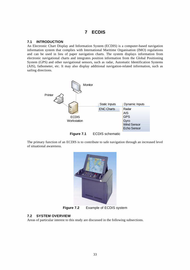
7.1 INTRODUCTION An Electronic Chart Display and Information System (ECDIS) is a computer-based navigation information system that complies with International Maritime Organisation (IMO) regulations and can be used in lieu of paper navigation charts. The system displays information from electronic navigational charts and integrates position information from the Global Positioning System (GPS) and other navigational sensors, such as radar, Automatic Identification Systems (AIS), fathometer, etc. It may also display additional navigation-related information, such as sailing directions.
i
i
Wii
i
i
Montor
Dynam c Inputs Radar AIS GPS Gyro
nd Sensor Echo Sensor
ECDIS Workstaton
Pr nter
Stat c Inputs ENC Charts
Figure 7.1 ECDIS schematic
The primary function of an ECDIS is to contribute to safe navigation through an increased level of situational awareness.
Figure 7.2 Example of ECDIS system
7.2 SYSTEM OVERVIEW Areas of particular interest to this study are discussed in the following subsections.
33

7.2.1 Radar interfacing The ability to present the ships’ radar image and ARPA information on the ECDIS display so that when the radar image is added to the ECDIS display, the chart and the radar image match in scale and in orientation.
7.2.2 Route planning The ability to carry out route planning within ECDIS including the adjustment of a planned route by, for example:
• adding waypoints to a route; • deleting waypoints from a route; • changing the position of a waypoint; • changing the order of the waypoints in the route.
ECDIS also allows the planning of alternative routes in addition to the selected route. The selected route is clearly distinguishable from the other routes within the system. The system will also provide an indication if the mariner plans a route across an own ship’s safety contour thereby reducing the risk of grounding.
7.2.3 Route monitoring For route monitoring the selected route and own ship’s position appears whenever the display covers that area. It is possible to display a sea area that does not have the ship on the display (e.g., for look ahead, route planning), while route monitoring.
ECDIS can also be set to sound an alarm if, within a specified time set by the mariner, own ship will cross the safety contour, prohibited area or of a geographical area for which special conditions exist. An alarm can also be sounded when the specified limit for deviation from the planned route is exceeded.
7.2.4 Voyage recording ECDIS stores and has the ability to reproduce certain minimum elements required to reconstruct the voyage. The following data is recorded at one minute intervals:
• Time • Position • Heading • Speed • ENC details, e.g., source, edition, date, cell and update history.
In addition, ECDIS records the complete track for the entire voyage, with time marks at intervals not exceeding 4 hours. It is not possible to manipulate or change the recorded information and ECDIS.
7.3 ELECTRONIC CHARTS IN ECDIS When used in the Raster Chart Display System mode (RCDS), the International Maritime Organisation (IMO) performance standards (A.817(19) which was amended in 1996 by resolution MSC.64 (67) and further amended in 1998 by resolution MSC 86 (70)) stipulate that the system has to be used “in conjunction with an appropriate portfolio of up-to-date paper charts”. The performance standards give no guidance on what constitutes an “appropriate” portfolio of paper charts.
34
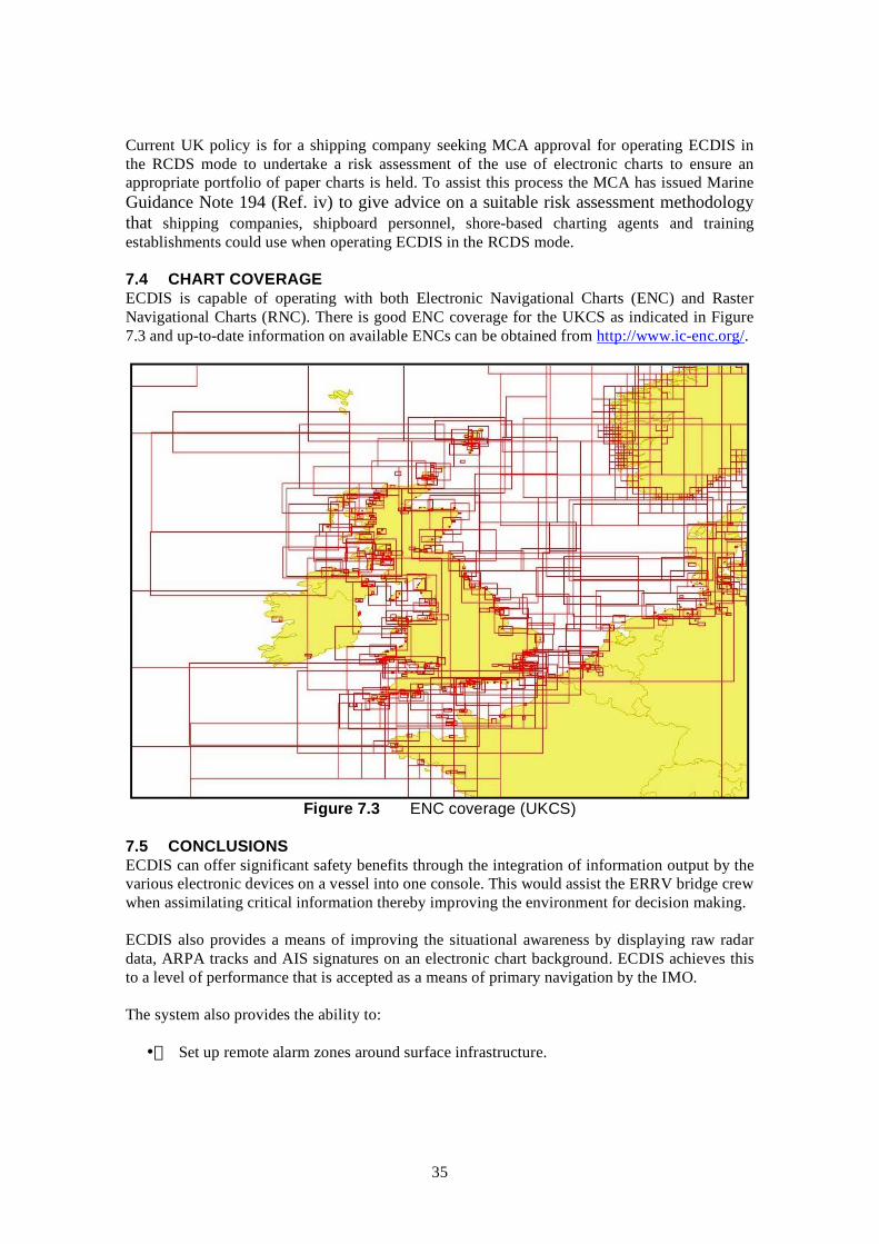
Current UK policy is for a shipping company seeking MCA approval for operating ECDIS in the RCDS mode to undertake a risk assessment of the use of electronic charts to ensure an appropriate portfolio of paper charts is held. To assist this process the MCA has issued Marine Guidance Note 194 (Ref. iv) to give advice on a suitable risk assessment methodology that shipping companies, shipboard personnel, shore-based charting agents and training establishments could use when operating ECDIS in the RCDS mode.
7.4 CHART COVERAGE ECDIS is capable of operating with both Electronic Navigational Charts (ENC) and Raster Navigational Charts (RNC). There is good ENC coverage for the UKCS as indicated in Figure 7.3 and up-to-date information on available ENCs can be obtained from http://www.ic-enc.org/.
Figure 7.3 ENC coverage (UKCS)
7.5 CONCLUSIONS ECDIS can offer significant safety benefits through the integration of information output by the various electronic devices on a vessel into one console. This would assist the ERRV bridge crew when assimilating critical information thereby improving the environment for decision making.
ECDIS also provides a means of improving the situational awareness by displaying raw radar data, ARPA tracks and AIS signatures on an electronic chart background. ECDIS achieves this to a level of performance that is accepted as a means of primary navigation by the IMO.
The system also provides the ability to:
• Set up remote alarm zones around surface infrastructure.
35

• Operate in ENC mode where alarms can be established to guard and protect subsea infrastructure for example. • Record information to assist in accident review and playback. • Established approach areas and speed restrictions around an installation for infield vessels and alarm on the vessel if these are breached. • Interface with the installation to provide improved real time information on the bridge of vessels working within proximity to the field (see Section 7.2 on Maritime Electronic Highways which provides example of this).
ECDIS also offers more general potential benefits to marine personnel working in the oil & gas industry, e.g., reduced workload for Officers of the Watch in maintaining paper charts.
36

8 VOYAGE DATA RECORDERS (INCLUDING S-VDRS)
8.1 INTRODUCTION Voyage Data Recorders (VDRs) are data recording devices that collect data from various sensors on board the vessel and then digitises, compresses and stores it in an externally mounted protective storage unit.
Figure 8.1 Typical VDR
The schedule for the fitting of VDRs is stated within Regulation 20 of SOLAS as presented in Table 8.1.
Table 8.1 Timetable for fitting of voyage data recorders Para. Type of Vessel Date by which VDR must be
fitted
1.1 Passenger ships constructed on or after 1 July 2002 Date of build
1.2 Ro-Ro passenger ships constructed before 1 July 2002 Date of first survey on or after 1 July 2002
1.3 Passenger ships other than ro-ro constructed before 1 July 2002 1 January 2004
1.4 Ships other than passenger ships of 3,000 gt. and upwards constructed on or after 1 July 2002 Date of build
Note: Administrations may exempt ships, other than ro-ro passenger ships, constructed before 1 July 2002, from being fitted with a VDR where it can be demonstrated that interfacing a VDR with the existing equipment on the ship is unreasonable and impracticable
An alternative specification has been established for a Simplified Voyage Data Recorder (S-VDR) for use by cargo vessels in order to reduce the cost of a full VDR installation. The original VDR specifications are still required for passenger ships, tankers, and those carrying hazardous cargo however the International Maritime Organisation approved the mandatory requirement for the S-VDR system during December 2005.
The new rules stipulate that existing cargo ships on international voyages shall be fitted with an S-VDR as follows:
37
2010
• 20,000 gross tonnage and upwards constructed before 1 July 2002, at the first scheduled dry-docking after 1 July 2006 but not later than 1 July 2009
• 3,000 gross tonnage and upwards but less than 20,000 gross tonnage constructed before 1 July 2002, at the first scheduled dry-docking after 1 July 2007 but not later than 1 July
• Administrations may exempt cargo ships from the application of the requirements when such ships will be taken permanently out of service within two years after the implementation date specified above.
Any non SOLAS vessel or installation can install VDRs or S-VDRs as there is no restriction on their use.
8.2 SYSTEM OVERVIEW The protective storage unit is a tamper-proof unit designed to withstand the extreme shock, impact, pressure and heat, which could be associated with a marine incident (e.g., fire, explosion, collision, sinking, etc). The VDR can either be a fixed unit or free floating unit (or combined with EPIRB). The last 12 hours of stored data can be recovered and replayed by the authorities or ship owners for incident investigation.
38

Figure 8.2 VDR overview
Performance standards for VDRs were adopted in 1997 and give details on data to be recorded and VDR specifications. They state that the VDR should continuously maintain sequential records of preselected data items relating to status and output of the ship’s equipment and command and control of the ship (see Table 8.2 and Table 8.3). The VDR should be installed in a protective capsule that is brightly coloured and fitted with an appropriate device to aid location. It should be entirely automatic in normal operation.
39

Table 8.2 VDRs data items Resolution A.861(20) Ref
Data Item Source
5.4.1 Date & time Preferably external to ship (e.g., GNSS) 5.4.2 Ship’s position Electronic Positioning system 5.4.3 Speed Ship’s SDME 5.4.4 Heading Ship’s compass 5.4.5 Bridge Audio 1 or more bridge microphones 5.4.6 Comms. Audio VHF 5.4.7 Radar data Master radar display 5.4.8 Water depth Echo Sounder 5.4.9 Main alarms All mandatory alarms on bridge 5.4.10 Rudder order & response Steering gear & autopilot 5.4.11 Engine order & response Telegraphs, controls and thrusters
5.4.12 Hull openings status All mandatory status information displayed on bridge
5.4.13 Watertight & fire door status All mandatory status information displayed on bridge
5.4.14 Acceleration & hull stresses Hull stress and response monitoring equipment where fitted
5.4.15 Wind speed & direction Anemometer when fitted
Table 8.3 S-VDRS data items Resolution MSC.163(78) Ref
Data Item Source
5.4.1 Date & time Preferably external to ship (e.g., GNSS) 5.4.2 Ship’s position Electronic Positioning system 5.4.3 Speed Ship’s SDME 5.4.4 Heading Ship’s compass 5.4.5 Bridge Audio 1 or more bridge microphones 5.4.6 Comms. Audio VHF 5.4.7 Radar data Master radar display 5.4.8 AIS Data AIS receiver
Under the new regulation, all VDRs must undergo an annual performance test.
Under Resolution MSC.214(81) which was adopted in 13th May 2006 it is a recommendation that governments ensure that VDRs and S-VDRs:
• if fitted before 1 June 2008, conform to performance standards not inferior to those specified in the Annexes to resolutions A.861(20) and MSC.163(78), respectively; and
• if fitted on or after 1 June 2008, conform additionally to the amendments to performance standards not inferior to those specified in Annexes 1 and 2 of the 214(81) resolution.
40

The Annexes to these resolutions relate to the download and playback equipment for investigation authorities and require that:
• The VDR should provide an interface for downloading the stored data and playback the information to an external computer. The interface should be compatible with an internationally recognized format, such as Ethernet, USB, FireWire, or equivalent.
• A copy of the software programme providing the capability to download the stored data and playback the information onto a connected external laptop computer and for the playback of the data should be provided for each VDR/S-VDR installation.
• The software should be compatible with an operating system available with commercial-off-the-shelf laptop computers and provided on a portable storage device such as a CD-ROM, DVD, USB-memory stick, etc.
• Instructions for executing the software and for connecting the external laptop computer to the VDR/SVDR should be provided.
• The portable storage device containing the software, the instructions and any special (not commercial-off-the-shelf) parts necessary for the physical connection of the external laptop computer, should be stored within the main unit of the VDR/S-VDR.
• Where non-standard or proprietary formats are used for storing the data in the VDR, the software for converting the stored data into open industry standard formats should be provided on the portable storage device or resident in the VDR/S-VDR.
Many software products also offer the possibility of carrying out trend analysis to monitor performance of parameters, for example, speed vs. rpm. The playback functions can also provide a valuable tool for scenario-driven crew training and recording best practices.
41

Figure 8.3 VDR playback software
Data access is not limited to the crew of the vessel as certain systems allow the transfer of a compressed data file from ship to shore via satellite communication to provide shore-side personal access to everything recorded by the VDR, including hull stress, bilge levels, engine status, watertight doors, navigational data and other shipboard data.
8.3 POTENTIAL USE IN OIL AND GAS INDUSTRY SOLAS classed production and drilling systems, e.g., FPSOs and mechanically propelled MODU’s will be required to have VDRs or S-VDRs installed. In addition VDRs will be installed on all field vessels >3,000 GT which will include many ERRVs and PSV’s, etc. For those <3,000 GT it is possible to install VDR’s as there is no restrictions in their use.
Due to the capability of the equipment there is benefit that can be taken by the oil and gas industry.
The primary benefit from VDRs is to assist in accident and incident investigation which may be required should there be a maritime incident offshore it will act as a black box recorder of all the data specified in Table 8.2 and Table 8.3. This will include all vessels being tracked by the ERRV including own ships behaviour (radar and AIS), VHF calls made and responses received, etc.
In addition the data being received by the VDR/S-VDR can be used for preventive maintenance, performance efficiency monitoring, heavy weather damage, accident avoidance and training purpose to improve safety and reduce running costs.
There is also the prospect to use the VDR information to confirm the vessels are operating in line with field procedures, for training competency assessment through review and also to assist in the assessment of best practice.
42

VDRs/S-VDRs can be installed on any structure/platform or vessels and there is no exclusivity to their use on SOLAS vessels.
43

9 E-NAVIGATION
9.1 INTRODUCTION At its 81st session the IMO Maritime Safety Committee included a high priority item on "Development of an E-navigation strategy" within the work programmes of the NAV and Radiocommunications and Search and Rescue (COMSAR) Sub-Committees.
The aim is to develop a strategic vision for E-navigation, to integrate existing and new navigational tools, in particular electronic tools, in a system that will contribute to enhanced navigational safety (with all the positive repercussions this will have on maritime safety overall and environmental protection) while simultaneously reducing the burden on the navigator.
The IMO are to take the lead in E-navigation but other organisations are to participate in its work and provide relevant input, in particular, the International Association of Marine Aids to Navigation and Lighthouse Authorities (IALA) and the International Hydrographic Organization (IHO).
9.2 SYSTEM OVERVIEW The primary user requirements of e-navigation are to satisfy the key functions in getting a ship safely between its departure and destination points. The key functions of this have been identified as:
• Voyage planning • Monitoring of the voyage plan • Position fixing • Collision avoidance • Manoeuvring and conning the vessels • Communications • Recording of navigational events • Voyage reporting
In doing so it is also identified that there is the need to link the role of the shore infrastructure in supporting the relevant navigational functions.
An example of E-navigation is the Marine Electronic Highway, IMO's 'E navigation' project in the Straits of Malacca and Singapore, which will offer the prospect of linking a shore-based marine information and communications infrastructure with the corresponding navigational and communication facilities onboard transiting ships; while also being capable of incorporating marine environmental management aids.
Essentially, the Marine Electronic Highway is being built upon a network of electronic navigational charts using ECDIS and environmental management tools, all combining in an integrated platform covering the region that allows the maximum of information to be made available both to ships and shipmasters as well as to shore-based users, such as vessel traffic services.
The overall system - which, in addition to electronic navigational charts, would include positioning systems, AIS, real-time navigational information like tidal and current data, as well as providing meteorological and oceanographic information - is designed to assist in the overall
44

traffic management of the Straits and provide the basis for sound marine environmental protection management. It is seen to be a tool for the planning and organization of pollution prevention and control operations, not to mention the safety of navigation in the region.
It will be used not only for search and rescue, navigational safety and environmental protection purposes, but also for security purposes.
Figure 9.1 MEH demonstrator project
45
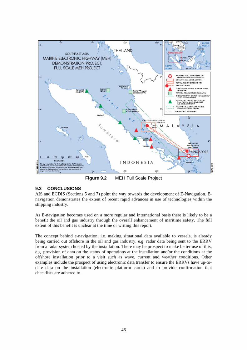
Figure 9.2 MEH Full Scale Project
9.3 CONCLUSIONS AIS and ECDIS (Sections 5 and 7) point the way towards the development of E-Navigation. E-navigation demonstrates the extent of recent rapid advances in use of technologies within the shipping industry.
As E-navigation becomes used on a more regular and international basis there is likely to be a benefit the oil and gas industry through the overall enhancement of maritime safety. The full extent of this benefit is unclear at the time or writing this report.
The concept behind e-navigation, i.e. making situational data available to vessels, is already being carried out offshore in the oil and gas industry, e.g. radar data being sent to the ERRV from a radar system hosted by the installation. There may be prospect to make better use of this, e.g. provision of data on the status of operations at the installation and/or the conditions at the offshore installation prior to a visit such as wave, current and weather conditions. Other examples include the prospect of using electronic data transfer to ensure the ERRVs have up-to-date data on the installation (electronic platform cards) and to provide confirmation that checklists are adhered to.
46
10 LONG RANGE IDENTIFICATION AND TRACKING (LRIT)
10.1 INTRODUCTION At its 81st session in May 2006 The Maritime Safety Committee (MSC) adopted new regulations for the long range identification and tracking (LRIT) of vessels together with associated performance standards and functional requirements.
The new regulation on LRIT is included in SOLAS chapter V on Safety of Navigation, through which LRIT will be introduced as a mandatory requirement for the following ships on international voyages:
• passenger ships, including high-speed craft; • cargo ships, including high-speed craft, of 300 gross tonnage and upwards, and; • mobile offshore drilling units.
The SOLAS regulation on LRIT establishes a multilateral agreement for sharing LRIT information for security and search and rescue purposes, amongst SOLAS Contracting Governments, in order to meet the maritime security needs and other concerns of such Governments.
10.2 SYSTEM OVERVIEW The LRIT information ships will be required to transmit include:
• Ship's identity; • Ship’s location; • Date and time of position.
Primarily the data will be transmitted at 6 hour intervals by tracking transponders fitted on the ships. LRIT data centres operated by its flag of administration can poll the ship to alter the transmission schedule and this process will not require input from the crew. The ship will also not incur any costs for the satellite transmissions tied to LRIT.
There will be no interface between LRIT and AIS. One of the more important distinctions between LRIT and AIS, apart from range, is that, whereas AIS is a broadcast system, data derived through LRIT will be available only to the recipients who are entitled to receive such information and safeguards concerning the confidentiality of those data are built into the regulatory provisions.
47

Figure 10.1 LRIT system schematic
Under LRIT, SOLAS Contracting Governments will be entitled to receive information about ships navigating within a distance not exceeding 1,000 nautical miles off their coast.
LRIT information will only be available to:
• The flag administration. • The administration of the port facility the ship intends to enter; and • The administration of the waters through which the ship is transiting within a distance not exceeding 1,000 nautical miles off its coast.
The regulation is expected to enter into force on 1 January 2008 and will apply to ships constructed on or after 31 December 2008 with a phased-in implementation schedule for ships constructed before 31 December 2008.
LRIT is intended to be operational with respect to the transmission of LRIT information by ships as from 31 December 2008. There is an exemption for ships operating exclusively in Sea Area A1 from the requirement to transmit LRIT information, since such ships are already fitted with AIS.
“Sea Area A1" means an area within the radiotelephone coverage of at least one VHF coast station in which continuous DSC alerting is available, and specified as such an area in Volume 5 of the Admiralty List of Radio Signals.
10.3 CONCLUSIONS Due to the restrictions on the accessibility of LRIT data there will be limited operational benefit to the Oil and Gas industry.
The Maritime and Coastguard Agency will use the system for security and terrorist monitoring which will offer security benefit to oil and gas industry.
The last position of a vessel or MODU can be obtained from LRIT (via the appropriate routes) to aid search and rescue operations.
Due to their size, the majority of offshore support vessels will be required to carry LRIT transmitters.
48

11 IMO ROUTEING MEASURES
11.1 INTRODUCTION The purpose of routeing measures is to aid the safety of navigation by requiring or advising certain categories of ships or ships carrying certain cargoes to follow designated routes or to avoid certain areas of the sea. Ships’ routeing may also be used for preventing the risk of pollution or other damage to the marine environment in or near environmentally sensitive sea areas.
11.2 STANDARD INDUSTRY PRACTICE Two measures that are common within the Oil and Gas sector are safety zones and development areas.
11.2.1 Safety zones Article 60 of the United Nations Convention on the Law of the Sea (UNCLOS) enshrines the rights of coastal States to construct and to authorise and regulate the construction, operation and use of artificial islands, installations and structures in the exclusive economic zone.
The coastal State may, where necessary, establish reasonable safety zones around such structures in which it may take appropriate measures to ensure the safety both of navigation and of the structures.
UNCLOS states that the breadth of the safety zones shall be determined by the coastal State taking into account applicable international standards. Such zones shall be designed to ensure that they are reasonably related to the nature and function of the artificial islands, installations or structures, and shall not exceed a distance of 500 metres around them, measured from each point of their outer edge, except as authorized by generally accepted international standards or as recommended by the competent international organization.
All ships must respect these safety zones and shall comply with generally accepted international standards regarding navigation in the vicinity of artificial islands, installations, structures and safety zones.
In the UK, a safety zone of 500 metres radius is automatically established around all offshore oil and gas installations which project above the sea at any state of the tide. Some subsea installations also have safety zones created by statutory instrument to protect them. Vessels of all nations are required to respect them. In the UK, it is an offence (under section 23 of the Petroleum Act 1987) to enter a safety zone except under the special circumstances outlined below.
UNCLOS also states that installations and the safety zones around them may not be established where interference may be caused to the use of recognized sea lanes essential to international navigation. In the UK, offshore oil and gas installations may be located only with Consent to Locate from the DTI. Three Acts provide the statutory framework governing Consent to Locate offshore installation on the UKCS:
• Coast Protection Act 1949
• Continental Shelf Act 1964
49

• Merchant Shipping Act 1988
These provisions require prior written consent to be obtained from the DTI to construct, alter or improve any works on, under or over tidal waters on the UKCS where danger or obstruction to navigation is likely to result. This covers all exploratory operations (except seismic surveys from vessels) and installation of production facilities, including pipelines.
When assessing an application, the DTI make judgments on the following matters:
• Evidence of shipping movements close to the proposed locations;
• Likely changes in those movements resulting from an installation;
• Constraints imposed upon local navigation by the installation;
• The danger of passing vessels colliding with the installation;
• The increased danger of ships colliding with each other, or having other misfortune, as a result of needing to avoid the installation;
• If appropriate the scope for reducing risk by taking counter measures.
It is considered good practice to address both the level of obstruction to navigation and risk to personal together at a very early stage of the development planning process.
The guidance to the Coast Protection Act states that operations in charted Deep Water Routes, Traffic Separation Schemes, and the approaches to such routes, will usually obstruct and endanger navigation and consents for sites in such waters are unlikely to be given, especially for fixed surface installations.
11.2.2 Development areas Certain fields in the UK which are in a development phase or are currently producing oil and gas, are designated development areas. Development areas are marked on hydrographic charts and although entry is not prohibited, mariners are strongly advised to keep outside these areas. The following figure presents an overview of the development area in place around the Amethyst field in the Southern North Sea.
50
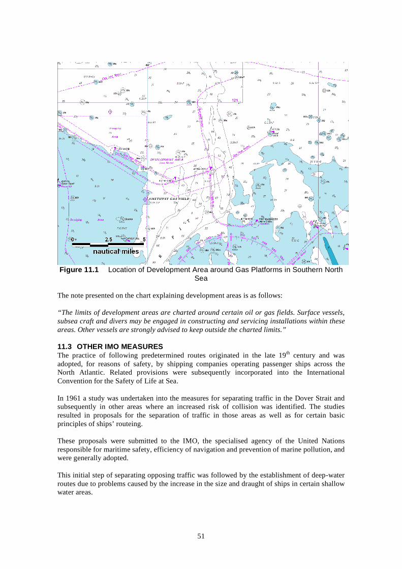
Figure 11.1 Location of Development Area around Gas Platforms in Southern North Sea
The note presented on the chart explaining development areas is as follows:
“The limits of development areas are charted around certain oil or gas fields. Surface vessels, subsea craft and divers may be engaged in constructing and servicing installations within these areas. Other vessels are strongly advised to keep outside the charted limits.”
11.3 OTHER IMO MEASURES The practice of following predetermined routes originated in the late 19th century and was adopted, for reasons of safety, by shipping companies operating passenger ships across the North Atlantic. Related provisions were subsequently incorporated into the International Convention for the Safety of Life at Sea.
In 1961 a study was undertaken into the measures for separating traffic in the Dover Strait and subsequently in other areas where an increased risk of collision was identified. The studies resulted in proposals for the separation of traffic in those areas as well as for certain basic principles of ships’ routeing.
These proposals were submitted to the IMO, the specialised agency of the United Nations responsible for maritime safety, efficiency of navigation and prevention of marine pollution, and were generally adopted.
This initial step of separating opposing traffic was followed by the establishment of deep-water routes due to problems caused by the increase in the size and draught of ships in certain shallow water areas.
51

Similarly, the hazards to navigation in certain areas and the associated danger to the marine environment have resulted in the establishment of “areas to be avoided” by certain ships.
Today, in accordance with chapter V of the International Convention for the Safety of Life at Sea (SOLAS), IMO is recognised as the only international body for establishing and adopting measures on an international level concerning routeing and areas to be avoided by ships or certain classes of ships.
The following list indicates typical IMO routeing measures currently in existence:
(i) Traffic separation scheme (TSS): A routeing measure aimed at separating opposing streams of traffic by appropriate means and by the establishment of traffic lanes. Unless a routeing measure has been designated as a mandatory ships’ routeing scheme, the use of a traffic separation scheme is optional.
However, if a vessel decides to use such a scheme, it must abide by the requirements of Rule 10 of the International Regulations for Preventing Collision at Sea 1972, as amended (“COLREGS”). A typical example is the traffic separation scheme in the Dover Strait and adjacent waters;
(ii) Areas to be avoided (ATBA): A routeing measure comprising an area within defined limits in which navigation is either difficult or where it is exceptionally important to avoid incidents including collisions and groundings and which should be avoided by all ships, or certain classes of ships. Examples include areas to be avoided in the region of the Shetland and Orkney Islands and the Fair Isle which were established to avoid the risk of oil pollution and severe damage to the environment and economy of the region;
(iii) Deep water route (DWR): A route within defined limits which has been accurately surveyed for clearance of the sea bottom and submerged obstacles, as indicated on Admiralty charts.
(iv) Other routeing measures: including two-way routes, recommended tracks, no anchoring areas, inshore traffic zones, roundabouts and precautionary areas.
In accordance with paragraphs 3.14 to 3.16 of the General Provisions on Ships' Routeing, Governments which establish routeing measures wholly within their territorial seas or in straits used for international navigation, are requested by the IMO to design them in accordance with IMO guidelines and criteria for such schemes and submit them to IMO for adoption. The UK will abide by this guidance, so that all routeing measures have international acceptance. In the unlikely event that the IMO did not approve a routeing measure the UK would carefully consider the reasons for it being rejected but reserves the right to implement a routeing measure if it is compliant with international law.
Unless specific routeing measures have been made mandatory they are generally of a recommendatory nature. Also, a routeing measure’s application to vessels is agreed when the measure is adopted and is described in the description of the specific measure in the IMO “Ships’ Routeing ” Publication. COLREG Rule 10 does not require vessels to use traffic separation schemes (e.g. certain vessels can use inshore traffic zones adjacent to a TSS) but does require them to behave in a particular way if they decide to use them.
52

Unless expressly provided otherwise, the application of Chapter V (Safety of Navigation) of the Safety of Life at Sea (SOLAS) Convention applies to all ships on all voyages. Although a national maritime administration can decide to what extent the provision of certain regulations apply for ships below 150 gross tonnage engaged on any voyage, ships below 500 gross tonnage not engaged on international voyages and fishing vessels, no such determination exists of Regulation 10 dealing with Ships’ Routeing. Compliance with the COLREGS is mandatory for all vessels on the high seas, and in all waters connected to the high seas and navigable by seagoing vessels, used or capable of being used as a means of transportation on water.
The MCA will consider routeing measure solutions as part of a scheme for management of risk in a sea area and it is unlikely that routeing measures will be implemented on a piecemeal basis.
The MCA will also utilise the UKSON Committee in developing a routeing measure proposal. Only when a scheme has been agreed by UKSON members will it go forward to the IMO for approval and adoption. The following bullets provide an overview of the process adopted by the MCA when implementing the Humber TSS.
• MCA and Trinity House held initial discussions with ABP Humber personnel to discuss the scheme in general.
• First draft of the scheme presented to the UK Safety of Navigation (UKSON) committee for consideration.
• Several iterations of the scheme were needed before UKSON was content that the scheme complied with the IMO Routeing Guide, that compliance with the requirements of COLREG Rule 10 was guaranteed and that the standard of hydrographic surveys underpinning the proposed TSS were to IMO modern standards.
• MCA prepared a submission paper to the IMO Safety of Navigation Sub-Committee in accordance with the IMO guidelines for such submissions.
• Scheme examined and approved by the Routeing Working Group of the NAV Sub-Committee.
• Entered into force six months after endorsement by the Maritime Safety Committee.
11.4 CONCLUSIONS Routeing measures offer potential benefit in the management of marine risk in relation to oil and gas developments.
It can take significant time and national effort to implement routeing measures and as a result they tend to be used in more extreme cases where other risk management measure may not be available/suitable.
The following subsections provide example of the application of routeing measure to manage collision risk:
11.4.1 Designated anchorage areas Following a number of incidents with anchors impacting on pipelines and cables in the approaches to the Humber Estuary, BP in association with the port authority instigated a study to establish a recommended designated deep water anchorage in the area. This was established
53

to reduce the likelihood of a dragged anchor impacting on offshore oil and gas cables in the area.
The note presented on the chart explaining the anchorage area is as follows:
“Mariners are advised that this anchorage is recommended for large vessels bound for the Humber. Mariners are further advised that good holding ground is in the charted designated anchorages Nos 1,2 and 3. mariners are advised to keep their vessels in a state of readiness and to be prepared to get underway at short notice.”
Figure 11.2 presents an overview of the anchorage area as marked on a hydrographic chart for the area.
Figure 11.2 Location of deep water anchorage located to minimise hazards associated with cables and pipelines
11.4.2 Traffic separation scheme (TSS) An application has been made to IMO by the MCA to extend the Off Botney Ground Traffic Separation Scheme in the Southern North Sea. The extension of this scheme will allow for the development of oil and gas activities through the installation of platforms within the separation zone of the scheme. This will provide a greater separation distance between shipping and proposed oil and gas activities. The following figures show the area with the proposed TSS extension and associated separation zone
54
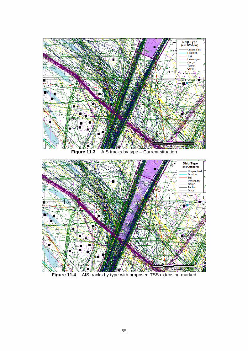
Figure 11.3 AIS tracks by type – Current situation
Figure 11.4 AIS tracks by type with proposed TSS extension marked
55

12 FISHING ACTIVITY SYSTEMS
12.1 KIS-UKCS Kingfisher Information Services UK Continental Shelf (KIS-UKCS) is a project run in co-operation with Oil & Gas UK aimed at promoting the awareness of oil and gas surface and subsea obstructions throughout the UK continental shelf.
It is a regular information service to inform fishermen of seabed obstructions via Kingfisher Yellow and Blue Cards which are published in the “Fortnightly Bulletin for Fishermen”, produced by Kingfisher in conjunction with Oil & Gas UK and the Scottish Executive. These cards list the positions of suspended wellheads and subsea operational wells in the North Sea and West of Shetland.
This information is also available in electronic chart/video plotter formats (as well as paper charts) under the KIS-UKCS project. Kingfisher Information / Sea Fish Industry Authority provide downloadable files for various fish plotter systems of all the surface and subsea oil and gas related installations for the UK continental shelf area.
Data for KIS-UKCS is supplied by oil and gas operators within the UK sector of the North Sea. It is then collated into a common standard, added to data from other sources such as the list of suspended wellheads compiled by Oil & Gas UK and the list of Safety Zones compiled by the Health & Safety Executive (HSE). The data is distributed by SeaFish free of charge (http://www.seafish.org).
12.2 KIS-CA Kingfisher Information Services – Cable Awareness (KIS-CA) – has a dedicated website (http://www.kisca.org.uk/) providing Submarine Cable locations and route information, including what to do and who to contact in an emergency.
The waters covered by the project are the North Sea, English Channel, Bristol Channel/Southwest Approaches, Irish Sea and West of Scotland (i.e. ICES Areas IV, VII and VI) and therefore include cables between the coasts of Norway, Denmark, Germany, Netherlands, Belgium, France, Ireland and the UK.
Fishermen are able to receive information on cable routes and other physical details (e.g., repeaters, splices, etc), together with emergency contact numbers and procedures in two formats:
• Paper charts - The production and distribution, free of charge to fishermen, of annual updated cable awareness charts. These are divided into six areas around the UK and show in-service and recently out-of-service cables.
• Electronic format - The production and free distribution of this data in electronic format, compatible with the most common fishing plotter systems. The data is also available for download over the Internet - both in readable text/graphic form as pdf files.
Within the UK, both the Scottish Fishermen's Federation (SFF) and the National Federation of Fishermen's Organisations (NFFO) are assisting with the local distribution of charts and discs, with Kingfisher organising physical distribution to the rest of Europe, Internet distribution, and the issue of licenses to electronic charting companies.
56

Cable awareness packs are also available to the SeaFish supported network of Group Training Associations (GTAs), who are responsible for organising fishermen's safety training in the UK, and any similar organisations in mainland Europe. Packs are to be available at SeaFish's Fisheries Development Centre, which is frequently visited by fishermen from across Northwest Europe, where small permanent cable awareness displays are to be mounted.
Figure 12.1 Kingfisher cable awareness chart (Central North Sea)
12.3 FISHSAFE FishSAFE is an electronic warning device that was developed in 1999 following the Westhaven fatal accident. FishSAFE gives an alarm on the bridge of fishing vessels when they are near oil pipelines or other subsea obstructions and legal exclusion zones, based on the KIS-UKCS data.
The system works by taking position from the onboard GPS receiver and using that to interrogate a comprehensive database of all pipelines, wellheads and cables throughout UK waters to find any nearby obstructions.
57

Figure 12.2 FishSAFE equipment
The key features of FishSafe are summarised below:
• Gives skippers more knowledge of potential hazards • Clear display of obstructions out to 6 miles • Can zoom in for maximum detail • Both visual and audio alarms • Uses new KIS-UKCS database • Suitable for any vessel
FishSAFE displays the following data types extracted from KIS-UKCS:
Surface Features • Platforms • FPSOs • Loading Buoys • Permanent marker buoys
Subsea Features • Suspended wellheads • Production wellheads • Manifolds • Templates • Other significant obstructions, including valves, piles, anchors and major debris • Pipelines • ‘Significant’ pipeline spans (i.e. over 10m long and 0.8m above the seabed) • 500m Safety Zones
12.4 SATELLITE MONITORING The Marine Fisheries Agency, an Executive Agency of the Department for Environment, Food and Rural Affairs (Defra), operates a satellite Vessel Monitoring System (VMS). The VMS is used, as part of the sea fisheries enforcement programme, to track the positions of fishing vessels exceeding 15 metres in overall length in UK waters. It is also used to track all UK-registered fishing vessels globally.
58

Vessel position reports are received approximately every 2 hours unless a vessel has a terminal on board which cannot be polled then it must report once per hour. The data covers all EC countries within British Fisheries Limits and certain Third Countries, e.g., Norway and Faroes. Vessels used exclusively for aquaculture and operating exclusively within baselines are exempt.
The tracking is carried out to meet the requirements of EC Regulation 2244/2003. To achieve this, the UK Fisheries Departments have established a technical specification for satellite-tracking devices to be installed onboard UK fishing vessels. This specification has been notified to the European Commission under the Technical Standards Directive 98/34/EC.
The identities of individual fishing vessels are not released but the following information is available:
• Date and Time • Vessel Unique Identifier (‘anonymised’) • Nationality • Gear Type (UK vessels only where available) • Speed and Course (where available)
A sample plot by nationality is presented below.
Figure 12.3 Fishing Vessel Satellite Tracking by Nationality off NE Scotland
12.5 CONCLUSIONS The KIS-UKCS and KIS-CA initiatives provide recent examples of how new technology is being used to improve safety and understanding of offshore operations within the sea fishing community.
Promulgating accurate and up-to-date information on oil and gas infrastructure to the fishing industry will assist in ensuring the two industries can work together safely and efficiently. Two
59

aspects require consideration; provision of data on permanent facilities and also for temporary operations such as drilling activities where operation details including anchor positions should be sent to [email protected]
FishSafe is another positive development co-funded by Oil & Gas UK following the Westhaven tragedy in 1997 when an Arbroath fishing vessel sank after snagging a pipeline.
These are ongoing developments which need support to ensure the information remains current as well as increasing the proportion of vessels carrying the warning devices.
Access to the fishing vessel satellite-tracking (VMS) data can be used to better understand fishing vessel activities in proximity to oil and gas structures. Since 2005 the data covers vessels above 15 metres in overall length which covers the majority of fishing activity near UK offshore fields. As well as indicating activity levels, the gear type information available for the UK fleet can be used to assess risks to subsea equipment from demersal (bottom) fishing gear, such as beam and otter trawlers.
12.5.1 Additional Information
12.6 GMDSS The Global Maritime Distress and Safety System (GMDSS) is an international system which uses terrestrial and satellite technology and ship-board radio-systems to ensure rapid, automated, alerting of shore based communication and rescue authorities, in addition to ships in the immediate vicinity, in the event of a marine distress.
Under the GMDSS regulations (chapter IV of the International SOLAS Convention), all commercial vessels of 300 gross tonnage and upwards engaged on international voyages must be equipped with radio equipment that conforms to international standards as set out in the system. The basic concept is that search and rescue authorities ashore, as well as shipping in the immediate vicinity of the ship in distress, will be rapidly alerted through satellite and terrestrial communication techniques so that they can assist in a coordinated search and rescue operation with the minimum of delay.
The system is intended to perform the following functions:
• Alerting (including position determination of the unit in distress) • Search and rescue coordination • Locating (homing) • Maritime safety information broadcasts • General communications • Bridge-to-bridge communications
Specific radio carriage requirements depend upon the ship's area of operation, rather than its tonnage. The system also provides redundant means of distress alerting, and emergency sources of power.
Specific equipment requirements for ships vary according to the sea area (or areas) in which the ship operates and the oceans are divided into four sea areas; A1 to A4. The main components of GMDSS are:
• Emergency Position-Indicating Radio Beacons (EPIRBs)
60

• NAVTEX • INMARSAT • High Frequency radiotelephone and radiotelex • Search and Rescue Radar Transponders • Digital Selective Calling
Several of these are discussed elsewhere in this study.
GMDSS telecommunications equipment is not reserved for emergency use only. The IMO encourages mariners to use that equipment for routine as well as safety telecommunications.
12.7 SPECIAL USE VHF CHANNELS A number of maritime channels are allocated for special uses only, or are available for priority users such as Coastguard. The following are of particular relevance to Collision Risk Management.
12.7.1 Channel 70 (156.525 MHz) – digital selective calling Channel 70 is used exclusively for Digital Selective Calling (DSC) under the Global Maritime Distress and Safety System (GMDSS). DSC is primarily intended to initiate ship/ship, ship/shore, and shore/ship radiotelephone and MF/HF radiotelex calls. DSC calls can also be made to individual stations, groups of stations, or all stations in range. Each DSC-equipped ship, shore station and group is assigned a unique 9-digit Maritime Mobile Service Identity (MMSI).
DSC equipment provides all the functionality of voice-only equipment and the following additional features:
• A transmitter can call a receiver automatically using Digital Selective Calling on Channel 70, using an MMSI.
• A distress button, which automatically sends a digital distress signal identifying the calling vessel and the nature of the emergency.
• A connection to a GPS receiver allowing the digital distress message to contain the distressed vessel's position.
The correct use of DSC alerts on Channel 70 has recently been highlighted in HSE Operations Notice 61 “Management of Collision Risk - Radio Communication between Offshore Installations, their Standby Vessels and Merchant Ships” issued in April 2003. This was instigated after the HSE became aware of several recent incidents where installations, or their attendant standby vessels, have been unable to establish radio communication with a vessel on a collision course with the installation. Investigation identified that radio procedures used to establish communications with the approaching vessels were often not correct, in that the initial calling was made on VHF Channel 16.
Duty holders on all installations were advised to verify that communication hardware, procedures and training meet the requirements of the GMDSS regulations, for both their installations and other rescue facilities that they may contract. Although the GMDSS applies to vessels, other installations needing to communicate with vessels in their vicinity at times of distress or urgency should be aware of the agreed GMDSS procedures. The correct method for
61

making a distress or urgency alert on VHF is to transmit the relevant DSC alert on channel 70, subsequent communication would proceed on channel 16 or channel 13.
12.7.2 Channel 16 (156.800 MHz) Channel 16 has traditionally been the international maritime VHF radio channel used for distress, safety and voice calling, monitored by SAR authorities, commercial ships and other vessel users alike. Under SOLAS (Safety of Life At Sea) it was obligatory that a “listening watch” be maintained on Channel 16 at all times. This obligation was removed in 2005 in light of DSC although many vessels still listen. From 31 January 2005, the UK Coastguard downgraded their watch on VHF Channel 16 from a dedicated "headset" watch to a "loudspeaker" watch. This lowers the chances of being heard.
12.7.3 Search-and-rescue and anti-pollution operations Certain channels have been set aside internationally for use in co-ordinated search-and-rescue (SAR) operations. In the UK, their use is co-ordinated with HM Coastguard as follows:
• In addition to its use in SAR operations, Channel 10 (156.500 MHz) is used during oil spills and other pollution incidents, and (in the UK only) to broadcast Marine Safety Information.
• Channel 67 (156.375 MHz) is used primarily for SAR operations and for safety communications with HM Coastguard.
• Channel 73 (156.675 MHz) is used primarily for SAR operations and for broadcasting Marine Safety Information in the UK.
12.8 NAVIGATIONAL WARNINGS The UKHO acts on behalf of the UK government as the NAVAREA I Co-ordinator and UK National Co-ordinator for Radio Navigational Warnings within the Worldwide Navigational Warning Service. As such, the UKHO is a focal point for receipt, assessment and promulgation of maritime safety information and issues any necessary Radio Navigation Warnings relevant to its area of responsibility.
The MCA is responsible for broadcasting the warnings issued by the UKHO to vessels at sea.
• NAVAREA I Warnings. In-force warnings are broadcast on SafetyNET immediately they are issued by the UKHO and then daily thereafter. Those relevant for the appropriate service areas of the UK NAVTEX transmitters are also broadcast twice/day on NAVTEX.
• UK Coastal Navigational Warnings - WZs. In-force warnings are broadcast by the appropriate NAVTEX station (Cullercoats, Niton, Portpatrick or Ostend) when they are first issued by the UKHO and then again at each routine transmission - every 4 hours. They are also normally broadcast by radio telephony (RT - voice) on VHF and/or MF from selected MCA locations on receipt and at 4 hourly intervals thereafter.
NAVTEX is an acronym for NAVigational TEXt messages. The NAVTEX system is used for the automatic broadcast of localised Maritime Safety Information (MSI) using Radio Telex (also known as Narrow Band Direct Printing, or NBDP). The international system operates worldwide in English on a frequency of 518 kHz. Range is over 250 nautical miles.
62

It is an integral part of the Global Maritime Distress and Safety System (GMDSS). Under the SOLAS convention, NAVTEX is compulsory on all vessels over 300 GRT engaged on international voyages. MCA guidance is that all pleasure and other small craft sailing around the coast or going offshore should have NAVTEX.
The simplest form of receiver incorporates a small printer which prints the output on a small roll of paper. The basic receiver can be programmed to receive specific transmitting stations and certain classes of messages. Messages which cannot be programmed out include distress messages, search and rescue messages, navigational warnings and meteorological warnings.
NAVTEX transmissions are generally routine broadcasts within an allocated slot time of ten minutes every four hours. However, urgent information, distress information, warnings of gales, etc., can be inserted into the system at any time.
Figure 12.4 Typical NAVTEX receiver
In terms of the offshore industry, the following will usually be considered as suitable for warnings:
• the presence of large unwieldy tows in congested waters • cable and pipe-laying activity, the towing of submerged objects for research or exploration purposes, the employment of submersible craft or other underwater operations • the establishment of offshore structures and mobile drilling rigs
For example, reporting of rig moves should take place in line with the requirements of the Coast Protection Act and HSE Operations Notice 6 guidance. This includes the MOD Hydrographer and Maritime and Coastguard Agency (MCA). This will ensure details of the drilling rig location are distributed via Notices to Mariners, NAVTEX and NAVAREA warnings, as well as to the appropriate Maritime Rescue Co-ordination Centre (MRCC).
12.9 M-NOTICES It is important that oil & gas personnel who charter vessels for use in the UK oil and gas industry are familiar with relevant UK maritime legislation and other guidance and regulations published by the MCA.
In particular, there are three different types of Marine Notices issued by the MCA:
• Merchant Shipping Notices: These are used to convey mandatory information that must be complied with under UK legislation. These MSNs relate to Statutory Instruments and contain the technical detail of such regulations.
63

• Marine Guidance Notices: These give significant advice and guidance relating to the improvement of the safety of shipping and of life at sea, and to prevent or minimise pollution from shipping.
• Marine Information Notices: These are intended for a more limited audience, e.g. training establishments or equipment manufacturers, or contain information which will only be of use for a short period of time, such as timetables for MCA examinations. MINs are numbered in sequence and have a cancellation date (which will typically be no more than twelve months after publication).
Within each series of Marine Notices suffixes are used to indicate whether documents relate to merchant ships (M), fishing vessels (F) or both (M+F).
12.10AIS-SART A research project was reported early in 2006 in which an SART (Search and Rescue Transponder) would emit signals on VHF in AIS mode. The Sub-Committee endorsed proposed draft amendments to the performance standards for Search and Rescue Transponder (SART) (currently resolution A.802(19))
The Sub-Committee also endorsed preliminary draft performance standards for survival craft AIS Search and Rescue Transmitter (AIS-SART) to supplement the existing SART performance standards and in turn endorsed draft proposed amendments to regulations in SOLAS chapter III to reflect the development of new AIS-SART performance standards.
Trials have also been carried out with AIS-SART which indicated that their performance is significantly better than that of radar-SART in poor weather conditions with their range of tracking being significantly greater.
12.11ELECTRONIC CHARTS There are currently two main types of charts:
• Electronic Navigational Charts (ENCs) • Raster Navigational Charts (RNCs)
ENCs are vector charts that also conform to IHO specifications. They are compiled from a database of individual items (‘objects’) of digitised chart data which can be displayed as a seamless chart. With ENC charts the data is “layered”, enabling the user to de-select certain categories of data, such as a range of soundings, which are not required at the time. This facility, as well as reducing chart clutter, enables the user to select a depth contour so providing an electronic safety contour which may automatically warn the watchkeeper when approaching shallow water.
64
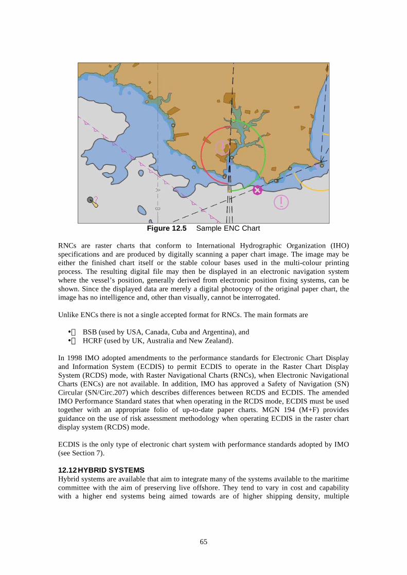
Figure 12.5 Sample ENC Chart
RNCs are raster charts that conform to International Hydrographic Organization (IHO) specifications and are produced by digitally scanning a paper chart image. The image may be either the finished chart itself or the stable colour bases used in the multi-colour printing process. The resulting digital file may then be displayed in an electronic navigation system where the vessel’s position, generally derived from electronic position fixing systems, can be shown. Since the displayed data are merely a digital photocopy of the original paper chart, the image has no intelligence and, other than visually, cannot be interrogated.
Unlike ENCs there is not a single accepted format for RNCs. The main formats are
• BSB (used by USA, Canada, Cuba and Argentina), and • HCRF (used by UK, Australia and New Zealand).
In 1998 IMO adopted amendments to the performance standards for Electronic Chart Display and Information System (ECDIS) to permit ECDIS to operate in the Raster Chart Display System (RCDS) mode, with Raster Navigational Charts (RNCs), when Electronic Navigational Charts (ENCs) are not available. In addition, IMO has approved a Safety of Navigation (SN) Circular (SN/Circ.207) which describes differences between RCDS and ECDIS. The amended IMO Performance Standard states that when operating in the RCDS mode, ECDIS must be used together with an appropriate folio of up-to-date paper charts. MGN 194 (M+F) provides guidance on the use of risk assessment methodology when operating ECDIS in the raster chart display system (RCDS) mode.
ECDIS is the only type of electronic chart system with performance standards adopted by IMO (see Section 7).
12.12HYBRID SYSTEMS Hybrid systems are available that aim to integrate many of the systems available to the maritime committee with the aim of preserving live offshore. They tend to vary in cost and capability with a higher end systems being aimed towards are of higher shipping density, multiple
65

platform guarding/ERRV sharing, and other bespoke set ups. Typical components of the higher end systems are as follows:
• Radar Signal processing and Tracking • Track Management • Sensor Management (cameras and weather stations) • SID transponders (infield vessel monitoring) • AIS transponder modules • Asset Tracking Devices • VOIP radio systems • Man-Over-Board Devices • Logistical Management Modules
12.13MARITIME DATA CENTRE (WWW.MARITIMEDATA.CO.UK) The Department of Trade and Industry has recently launched an online maritime data centre for the UK to promote the sharing of information between maritime stakeholders. The website (www.maritimedata.co.uk) is openly accessible thereby promoting the distribution and sharing of information. It features a Geographical Information System which allows viewing, interrogation and downloading of numerous data sets on maritime vessel activity, facilities and offshore development.
The project has been carried out in two phases:
• Phase 1: Completed and provides coverage of the three Strategic Environmental Areas of Greater Wash, Thames Estuary and North West (Liverpool Bay).
• Phase 2: Due for completion in 2007/8 and provides Coverage of the entire UKCS.
The development has received input from:
• Maritime and Coastguard Agency • Department for Transport • Department for Environment Food and Rural Affairs • The Crown Estate • Royal Yachting Association • Ministry of Defence • British Marine Aggregate Producers Association
Much of the information presented is useful to the oil and gas industry, for example, in screening potential impacts and sensitivities before bidding for licence blocks, in preparing Environmental Impact Assessments and in identifying potential consultees.
12.14THE MARINE SAFETY FORUM The Marine Safety Forum actively was set up to promote good safety practices and initiatives within the marine sector of the Northern European oil and gas industry. It is managed by a Steering Group of approximately 12 representatives from the membership and a secretary who meet every six weeks.
The work of the Marine Safety Forum is primarily carried out by "workgroups" which concentrate on a specific topic. The workgroup reports to the Steering Group with the eventual aim that a "Good Practice" regarding the specific issue is promulgated to the membership.
66

Every six months there is an All Members Meeting for the whole membership.
The primary aim is to improve safety within the marine sector of the industry - achieved by the following objectives:
• To air marine safety issues in an open forum of service users and providers. • To co-ordinate all marine industry workgroups and draw from industry expertise. • To highlight areas of particular concern and reach consensus on action required to minimise risk of major incidents. • To represent marine concerns within the "Step Change in Safety" initiative. • Take pre-emptive action on minor issues which have the potential to escalate. • To work together to share safety information and good practice across the whole industry.
In line with Step Change the overall target of the MSF is that "The UK is the safest place to work in the worldwide oil and gas industry by 2010."
67

13 CLOSING DISCUSSION
The way in which Operators manage their oil and gas fields is changing with the introduction of further ERRV sharing, and the use of combined operation vessels.
At all times it is the responsibility of the Operator to ensure that Regulation 17 of PFEER is met and also to demonstrate that collision risk is being effectively managed.
When assessing collision risk it is important to consider the impact strength of the structure when identifying the vessels (types, sizes, speeds) that pose threat to those working offshore, and then to ensure suitable systems are in place to manage these risks.
A field specific approach needs to be adopted as shipping characteristics and the operational requirements being placed upon the ERRV are location specific. As a result it needs to be demonstrated that the ERRV being used at the field is suitable and appropriately equipped for the way in which it is being used.
When developing and/or reviewing a collision risk management strategy for use offshore it is the responsibility of the Operator to ensure that regulations are being met and that best use is being made of the technologies that are available at that time. Equipment previously rejected on cost criteria may become more economic to use over time.
When considering the application of technologies care needs to be taken to ensure it is specified correctly. At present the IMO performance standards relate to using equipment for protection of the vessel upon which it is installed. This is not normally how the equipment is being applied offshore, as it tends to be used for the protection of assets offset from the scanner, and in practice the needs offshore can greatly exceed those of a vessel.
Trials are an essential part of this process as these can be used to demonstrate that the systems are providing the level of performance needed to preserve the safety of those working offshore from the threat of collision (in all weather conditions likely to be experienced). Marketing material is not a suitable method of demonstrating performance as this is often idealised.
Competence and manning levels require careful consideration, especially with more advanced equipment and when the tasks carried out become more complex, e.g. ERRV sharing between multiple assets.
Shipping is dynamic in nature and as a result collision risks vary over time. Regular reviews are required to demonstrate that the systems in place at the field are appropriate and that collision risks are being effectively managed. It is not suitable to implement systems indefinitely on the basis they were sufficient at the time as this can lead to serious shortfalls in the future.
Good communication between the oil & gas industry and the maritime industry needs to be continually developed to ensure both parties are aware of the advances and changing practices that are taking place.
The Maritime and Coastguard Agency and International Maritime Organisation provide a wealth of experience and information that can be used to assist in the management of safety with regard to offshore marine operations.
68

14 REFERENCES
i Effective Collision Risk Management for Offshore Installations, OTO 1999 052, Health & Safety Executive.
ii Guidelines for Ship/Installation Collision Avoidance, Oil & Gas UK, February 2003.
iii MCA, MGN 63 (M+F) Use of Electronic Aids to Navigation.
iv MCA, MGN 194 (M+F), Electronic Charts – The Use of Risk Assessment Methodology when Operating ECDIS in the Raster Chart Display System (RCDS) Mode.
69

70

Field TrialsRadar and AIS Comparison
(Appendix A)


CONTENTS
A1 INTRODUCTION ....................................................................................................1
A2 EQUIPMENT SPECIFICATION..........................................................................2
A3 TRACKS AND TRAFFIC LEVELS .....................................................................4
A4 DETECTION RANGE ANALYSIS ......................................................................6
A4.1 OVERALL.................................................................................................................6A4.2 VESSEL SIZE AND EFFECT OF WEATHER .............................................................. 6
A5 AIS CARRIAGE.......................................................................................................8
A6 AIS MANUAL DATA INPUT ACCURACY....................................................... 9
A7 RADIO CONTACT................................................................................................11
A8 GENERAL OBSERVATIONS.............................................................................12
A8.1 ARPA RADAR ......................................................................................................12A8.2 AIS SYSTEM .........................................................................................................13
A9 CONCLUSIONS .....................................................................................................16
A10 REFERENCES........................................................................................................17
A-i


A1 INTRODUCTION
This appendix presents the findings of field trials of vessel-based ARPA radar and AIS.
The trial was carried out onboard the multi-role Putford Enterprise ERRV / Supply vessel during normal operations whilst on location at the Shell Exploration and Production Clipper Field within the Southern North Sea in early April 2005.
The main objective of the trial was to assess the performance in terms of vessel detection and tracking of the AIS and ARPA onboard an ERRV in an offshore environment.
The results of an earlier survey in Autumn 2004 at the site of the planned London Array Offshore Windfarm in the Thames Estuary are also discussed where additional information is available.
A-1

A2 EQUIPMENT SPECIFICATION
Details on the radar and AIS equipment used in the Clipper trial are provided below:
• Radar: Furuno FR-2125 25 kW B Series, Type RP-2-124 Radar, with 4ft Scanner and ARPA
• AIS: JRC JHS-182 Class “A” Universal AIS
Figure 2.1 presents a photograph of the radar scanner and AIS antennae mounted on Putford Enterprise. The estimated height of the AIS antennae and radar scanner were estimated to be 16m and 17m above mean sea level, respectively.
A photograph of the radar and AIS display units on the bridge of the Putford Enterprise is presented in Figure 2.2.
Figure 2.1 Photograph of the Radar scanners and AIS antennae
A-2

Figure 2.2 Photograph of Radar and AIS display systems
A-3

A3 TRACKS AND TRAFFIC LEVELS
The tracks recorded by radar and AIS for the full 13 day survey period (1-13 April 2005) are presented below.
Figure 3.1 Radar tracks recorded during full survey period
Figure 3.2 AIS tracks recorded during full survey period
A-4
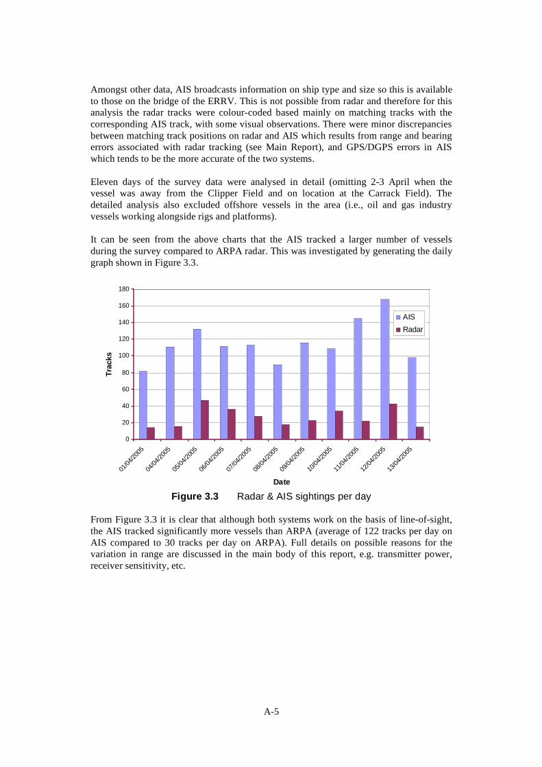
Amongst other data, AIS broadcasts information on ship type and size so this is available to those on the bridge of the ERRV. This is not possible from radar and therefore for this analysis the radar tracks were colour-coded based mainly on matching tracks with the corresponding AIS track, with some visual observations. There were minor discrepancies between matching track positions on radar and AIS which results from range and bearing errors associated with radar tracking (see Main Report), and GPS/DGPS errors in AIS which tends to be the more accurate of the two systems.
Eleven days of the survey data were analysed in detail (omitting 2-3 April when the vessel was away from the Clipper Field and on location at the Carrack Field). The detailed analysis also excluded offshore vessels in the area (i.e., oil and gas industry vessels working alongside rigs and platforms).
It can be seen from the above charts that the AIS tracked a larger number of vessels during the survey compared to ARPA radar. This was investigated by generating the daily graph shown in Figure 3.3.
0
20
40
60
80
100
120
140
160
180
01/04
/2005
04/04
/2005
05/04
/2005
06/04
/2005
07/04
/2005
08/04
/2005
09/04
/2005
10/04
/2005
11/04
/2005
12/04
/2005
13/04
/2005
Date
Trac
ks
AISRadar
Figure 3.3 Radar & AIS sightings per day
From Figure 3.3 it is clear that although both systems work on the basis of line-of-sight, the AIS tracked significantly more vessels than ARPA (average of 122 tracks per day on AIS compared to 30 tracks per day on ARPA). Full details on possible reasons for the variation in range are discussed in the main body of this report, e.g. transmitter power, receiver sensitivity, etc.
A-5

A4 DETECTION RANGE ANALYSIS
A4.1 OVERALL A more detailed analysis of detection ranges was carried out to compare the performance of both systems. This involved analysing the pick-up and drop-off ranges for AIS and drop-off range for ARPA (The pick-up range for ARPA was not considered as operational procedures required the radar display to be set at 16nm for the majority of the time). The results are presented in Figure 4.1.
0%
10%
20%
30%
40%
50%
60%
70%
80%
90%
100%
0 5 10 15 20 25 30 35 40 45 50 55 60
Detection Range (nm)
% V
esse
ls
AIS Average
Radar Average
Figure 4.1 Range of detection profile (ARPA vs. AIS)
For AIS, 98% of all vessels were detected at a distance of greater than 18nm, with 83% being detected at greater than 26nm. 64% of vessels were detected between 26 and 38nm. The greatest range at which a vessel was recorded was in the region of 90nm.
For the ARPA system, 82% of vessels had a drop off range in excess of 8nm, with 51% being 16nm or greater and 44% greater than 18nm. The maximum range was in the region of 32-34nm. It is noted that the majority of vessels in the lower drop-off ranges are as a direct result of targets being lost due to radar interference associated with multi-role vessel operations (see Section A8). Based on survey observations, it is concluded that the majority (>90%) of vessels were tracked to a minimum of 10nm.
A4.2 VESSEL SIZE AND EFFECT OF WEATHER Further analysis was conducted into vessel size and effect of weather on AIS and ARPA performance.
The performance of AIS was very consistent for the different weather conditions experienced during the trials, although higher range was noted on days with high pressure.
A-6

Vessel size (based on ship length broadcast on AIS) was not found to significantly influence AIS detection range in the Clipper trial, with both smaller and larger vessels being tracked over similar ranges. However, the earlier survey at London Array indicated a tendency for the AIS to pick up larger vessels at a greater range. This is considered to be reflective of the higher transmitter location on larger vessels which will improve the line of sight.
The radar performance exhibited more variation with weather conditions, for example, weather clutter tended to degrade performance. The locations, time periods and weather conditions experienced were not sufficiently varied to provide a full analysis of this affect, however, it is well-established from other research into ship-based radar that sea and atmospheric variations have a significant effect on detection capability (Ref. i).
Similarly, whilst it was not fully investigated in these trials, it is well-established that larger, higher targets generally have higher detection probabilities on radar due to their tendency to have a larger radar cross section area.
A-7

A5 AIS CARRIAGE
The proportion of vessels recorded on AIS was investigated to provide an indication of carriage levels.
Overall, approximately 90% of all vessels detected by ARPA during the survey were fitted with AIS. From radar track analysis and visual observations, vessels without AIS were found to be mainly fishing vessels, which is in line with the carriage requirements for AIS;
- “passenger ships, not later than 1 July 2003;
- tankers, not later than the first survey for safety equipment on or after 1 July 2003;
- ships, other than passenger ships and tankers, of 50,000 gross tonnage and upwards, not later than 1 July 2004.
- ships of 300 gross tonnage and upwards but less than 50,000 gross tonnage not later than the first safety equipment survey after 1 July 2004 or by 31 December 2004, whichever occurs earlier”
The proportion of non-AIS vessels will obviously vary in other parts of the UKCS, depending on the composition of traffic passing nearby, e.g., areas of high fishing activity would have a lower proportion of vessels on AIS.
A-8
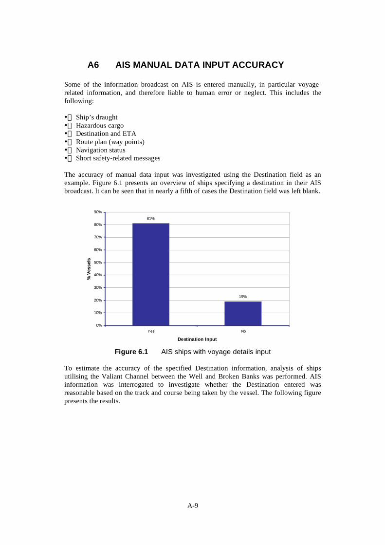
A6 AIS MANUAL DATA INPUT ACCURACY
Some of the information broadcast on AIS is entered manually, in particular voyage-related information, and therefore liable to human error or neglect. This includes the following:
• Ship’s draught • Hazardous cargo • Destination and ETA • Route plan (way points) • Navigation status • Short safety-related messages
The accuracy of manual data input was investigated using the Destination field as an example. Figure 6.1 presents an overview of ships specifying a destination in their AIS broadcast. It can be seen that in nearly a fifth of cases the Destination field was left blank.
81%
19%
0%
10%
20%
30%
40%
50%
60%
70%
80%
90%
Yes No
Destination Input
% V
esse
ls
Figure 6.1 AIS ships with voyage details input
To estimate the accuracy of the specified Destination information, analysis of ships utilising the Valiant Channel between the Well and Broken Banks was performed. AIS information was interrogated to investigate whether the Destination entered was reasonable based on the track and course being taken by the vessel. The following figure presents the results.
A-9

94%
6%
0%
10%
20%
30%
40%
50%
60%
70%
80%
90%
100%
Yes No
Correct Destination Input
% V
esse
ls
Figure 6.2 AIS ships with correct voyage details
Therefore, in the vast majority of cases (94%) the Destination information appeared accurate. In the other cases, it is likely that the Officer-of-the-Watch had not updated the information at the start of the current voyage.
Experience at other surveys has shown that other manually input fields can often be subject to input errors (such as spelling mistake or inaccurate data) or omitted. It has also been observed that vessels of the may broadcast a different type on AIS although this is uncommon.
Errors in these inputs are not considered to be critical in most cases although it could conceivably lead to confusion.
A-10

A7 RADIO CONTACT
Where vessels were not identified on AIS, radio contact was attempted in order to obtain details of the vessels and to determine the reason why AIS was not fitted. Radio contact was also attempted with vessels which were identified to have a projected CPA that encroached on an installations 500 metre safety zone. Attempted contact was made with a total of 22 vessels (3 with AIS and 19 non-AIS). The following figure presents the success rate.
100%
5%0%
95%
0%
10%
20%
30%
40%
50%
60%
70%
80%
90%
100%
AIS Non-AIS
Ship Type
VHF
Con
tact
Res
pons
e %
YesNo
Figure 7.1 Radio contact responses
All three vessels with AIS responded to VHF calls but only one non-AIS vessel answered. The non-AIS vessel was actually found to be a vessel with AIS which was defective. The remaining 18 vessels did not respond to radio calls.
It is considered that a better response rate was achieved from vessels with AIS as they were called by vessel name and/ or call sign rather than a call to an ‘anonymous’ vessel based only on its geographical position. In addition AIS vessels tend to be larger craft with non-AIS being related to fishing vessels whose crew may be busy fishing. Furthermore, the majority of vessels without AIS were not in close proximity to the Clipper Field and were therefore under no obligation to respond.
A-11

A8 GENERAL OBSERVATIONS
General observations made by survey personnel and bridge crew during the survey period have been included to provide operational details not picked up from the data analysis.
A8.1 ARPA RADAR General observations on the ARPA are listed below:
1. During cargo transfers when the survey vessel was in close proximity to the platform, target tracking on the far side of the platform was less effective. However, it was noted that the targets were still clearly visible on the radar display screen (i.e. no blind sector).
2. Acquired targets were lost when passing astern of ERRV at a range of 0-8nm. This was due to the position of the radar scanner relative to the vessel’s funnels which caused interference causing elongation of the echoes resulting in difficultly to track ships. However, it was noted that the targets were still clearly visible on the radar display screen (i.e. no blind sector).
3. Although support vessels in attendance at other platforms were clearly visible on the radar display unit, when acquired, the targets regularly jumped to the larger target of the attended platform when passing at a close distance. This is a typical occurrence (target swapping) when vessels are close to another structure (e.g. platform or buoy).
4. When acquired target passes through rain clutter (or vice versa) the target regularly jumps to the larger echo produced by the rain cloud.
An example of radar interference discussed in points 1 and 2 is presented below.
A-12

Figure 8.1 Example of Radar interference during cargo transfer
The above photograph of the radar display was taken during cargo transfer at the Clipper field. It is noted that the vessel was positioned to the southwest of the complex during transfers. As can be seen, targets to the far side of the platform and to the stern of the vessel have been elongated and proved difficult to acquire. Targets to the near side of the platform and in front of the vessel are unaffected during transfer operations.
A8.2 AIS SYSTEM General observations on the AIS are listed below:
• The AIS display unit automatically plots ship targets when VHF signals are received. The display range can be altered to the suit user requirements.
• Each ship identified is represented by a triangular icon which indicates the direction of travel. Through dial manipulation each target can be individually selected at the same time highlighting details of the ship bearing / range and name.
• During close standby duties and cargo transfer operations there was no effect on the detection performance of AIS (i.e. no blind sector).
• The following photograph shows the AIS display unit during normal operations.
A-13

Figure 8.2 AIS display unit indicating ships within 24nm of the survey vessel
• A full list of ships identified through VHF signals can be viewed on screen via the main menu. This includes vessels outside the range of the display setup (see figure below).
Figure 8.3 AIS display unit indicating list of ships identified
• Further details of each ship can be access through the main menu. These details are considered useful when attempting radio contact with approaching vessels as the vessel is
A-14

more likely to respond directly to its name and / or call sign than to geographical co-ordinates (Lat / Long) which are used when calling up based on radar information.
There are a variety of AIS displays beyond those presented in Figure 8.2 and Figure 8.3 and selection need carefully consideration to ensure the equipment used is fit for purpose. Further information on this is presented in the main body of the report.
A-15

A9 CONCLUSIONS
Based on the analysis of collected data and observations made while using the radar and AIS systems at the Clipper Field the following conclusions were made:
• The vast majority of vessels identified were fitted with AIS. In line with carriage requirements, the remainder were estimated to be small fishing vessels although one was found to be a vessel with defective AIS. This proportion of vessels carrying AIS will vary depending upon the location.
• The analysis identified that 98% of all vessels on AIS were tracked at a distance of greater than 18nm, with 83% being tracked at greater than 26nm. On ARPA radar based on target drop, 44% were tracked beyond 18nm. It is noted that the tracker drop range of ARPA will tend to be at greater ranges than the tracker pick up range.
• It was observed that AIS is not limited by the number of vessels that can be tracked whereas ARPA tends to be restricted to 20-40 simultaneous tracks (dependent of radar type / specification), with the user being able to select the vessels to be tracked. This can be a limitation of ARPA when monitoring traffic in areas with a high level of shipping, where priority may have to be given to vessels passing nearest the installation(s).
• The performance of AIS is consistent for the different weather conditions experienced during the survey trial. Radar and ARPA tended to be affected by weather clutter when acquired targets jumped to the larger echoes, e.g., rain clutter.
• The ARPA had difficulty when tracking vessel when they passed behind offshore installations especially during transfer operations when the ERRV was at close quarters to the installation. It was noted that the detection of the targets was not affected (i.e. no blind spots) just the tracking capability. The tracking capability of AIS was unaffected during close quarter operations.
• Vessel size was not found to significantly influence AIS detection range in the Clipper Field trial, with both small and larger vessels being tracked over similar ranges. The earlier London Array trial indicated a tendency for larger vessels to be tracked over greater range on AIS. It is well-established that target size and height affect the detection capability of radar,
• Whilst radio response was poor, this was mainly due to the vessels without AIS, e.g., fishing vessels not responding. When calling vessels equipped with AIS, these were much more likely to respond, as they are being called by name/call-sign, as opposed to ‘anonymous’ positional information from radar. The sample size was small for this assessment.
• Fishing vessels and very small craft were not tracked using AIS as these vessels are not required to carry this equipment. These vessels were tracked on the radar but not to a significant range and these targets were more easily lost to weather / sea clutter.
Based on the field trials, it is concluded that AIS presents an excellent aid to collision risk management, given its reliability, extended detection range as well as the additional vessel information provided to the ERRV.
A-16

i
A10 REFERENCES
HSE Offshore Technology Report OTO 97 058, Performance of Standby Vessel Radar, October 1997
A-17

Published by the Health and Safety Executive 09/07

Health and Safety Executive
Assessment of the benefits to the offshore industry from new technology and operating practices used in the shipping industry for managing collision risk There is a continuing duty for duty holders to manage risk and to keep possible risk reduction measures under review giving account to changing circumstances, advances in technology, new knowledge and information. Good practice may change over time; new technology may make a higher standard reasonably practicable. Continuous improvement leads to repeated challenge of existing measures and approaches to safety management.
In pursuit of this, this report provides an overview of the latest technologies being employed within the maritime industry which have the potential to benefit the oil and gas industry in support of their commitment to the management of collision risk. The study builds upon the previous work carried out by the HSE and Oil and Gas UK.
This report and the work it describes were funded by the Health and Safety Executive (HSE). Its contents, including any opinions and/or conclusions expressed, are those of the authors alone and do not necessarily reflect HSE policy.
RR592
www.hse.gov.uk