beneficial utilization of municipal solid waste
TRANSCRIPT

University of Central Florida University of Central Florida
STARS STARS
Electronic Theses and Dissertations, 2004-2019
2014
Beneficial Utilization of Municipal Solid Waste Incineration Ashes Beneficial Utilization of Municipal Solid Waste Incineration Ashes
as Sustainable Road Construction Materials as Sustainable Road Construction Materials
Kazi Tasneem University of Central Florida
Part of the Civil Engineering Commons
Find similar works at: https://stars.library.ucf.edu/etd
University of Central Florida Libraries http://library.ucf.edu
This Masters Thesis (Open Access) is brought to you for free and open access by STARS. It has been accepted for
inclusion in Electronic Theses and Dissertations, 2004-2019 by an authorized administrator of STARS. For more
information, please contact [email protected].
STARS Citation STARS Citation Tasneem, Kazi, "Beneficial Utilization of Municipal Solid Waste Incineration Ashes as Sustainable Road Construction Materials" (2014). Electronic Theses and Dissertations, 2004-2019. 4545. https://stars.library.ucf.edu/etd/4545

BENEFICIAL UTILIZATION OF MUNICIPAL SOLID WASTE INCINERATION ASHES
AS SUSTAINABLE ROAD CONSTRUCTION MATERIALS
by
KAZI MAHMUDA TASNEEM
B.S. Bangladesh University of Engineering & Technology, Bangladesh, 2006
M.S. Bangladesh University of Engineering & Technology, Bangladesh, 2010
M.S. Carnegie Mellon University, USA, 2011
A thesis submitted in partial fulfillment of the requirements
for the degree of Master of Science
in the Department of Civil, Environmental, and Construction Engineering
in the College of Engineering and Computer Sciences
at the University of Central Florida
Orlando, Florida
Summer Term
2014
Major Professor: BooHyun Nam

ii
© 2014 Kazi Mahmuda Tasneem

iii
ABSTRACT
Incineration of municipal solid waste (MSW) is common for energy recovery, and
management of municipal solid waste incineration (MSWI) ashes has received a growing
attention around the world. In the U.S., generation of MSW has increased up to 65% since
1980, to the current level of 251 million tons per year with 53.8% landfilled, 34.5% recycled
and composted, and 11.7% incinerated with energy recovery. In the process of incineration,
MSWI ash is being produced as byproducts; about 80 to 90% of the MSWI ash is bottom ash
(BA) and 10 to 20% is fly ash (FA) by weight. The current practice of the U.S. is to combine
both BA and FA to meet the criteria to qualify as non-hazardous, and all combined ashes are
disposed in landfills.
European countries have utilized MSWI BA as beneficial construction materials by
separating it from FA. The FA is mostly limited to landfill disposal as hazardous material due
to its high content of toxic elements and salts. BA has been actively recycled in the areas of
roadbed, asphalt paving, and concrete products in many of European and Asian countries. In
those countries, recycling programs (including required physical properties and
environmental criteria) of ash residue management have been developed so as to encourage
and enforce the reuse of MSWI ashes instead of landfill disposal. Moreover, many studies
have demonstrated the beneficial use of MSWI ashes as engineering materials with minimum
environmental impacts.
On the other hand, the U.S. has shown a lack of consistent and effective management
plans, as well as environmental regulations for the use of MSWI ashes., Due to persistent
uncertainty of engineering properties and inconsistency in the Federal and State regulations in

iv
the U.S., however, the recycling of the MSWI ashes has been hindered and they are mostly
disposed in landfills.
In this research work, current management practice, existing regulations, and
environmental consequences of MSWI ashes utilization are comprehensively reviewed
worldwide and nationwide with an emphasis of the potential area of its utilization in asphalt
paving and concrete product. This research also entails a detailed chemical and
microstructural characterization of MSWI BA and FA produced from a Refuse Derived Fuel
(RDF) facility in Florida so that the MSWI ash is well characterized for its beneficial uses as
construction materials.
The material characterization includes Scanning Electron Microscopy (SEM), Energy
Dispersive X-ray Spectroscopy (EDS), and X-ray Diffraction (XRD) techniques. In addition,
leaching experiments have been conducted to investigate the environmental properties (e.g.
leachate concentration) of BA and ash-mixed hot mix asphalt (HMA) and Portland cement
concrete (PCC). Leaching results reveals the reduced leaching potential of toxic material
from MSWI ashes while incorporated in HMA and PCC. Lastly, a preliminary experimental
approach has been devised for the vitrification of FA which is a promising thermal process of
transferring material into glassy state with higher physical and chemical integrity to reduce
toxicity so that utilization of FA can be possible.

v
Dedicated to my loving family

vi
ACKNOWLEDGMENTS
First of All, I pay my deepest gratitude to Almighty Allah for His graciousness,
benevolence and unlimited blessing.
This research work was performed in support of the Florida Department of
Transportation’s project, entitled as “Evaluating the Use of Waste-to-Energy Bottom Ash as
Road Construction Materials” under the contract BDK78-977-20.
I feel privileged to express my indebtedness and sincere thanks to my adviser Dr. Boo
Hyun Nam, Assistant Professor, Department of Civil, Environmental, and Construction
Engineering, University of Central Florida (UCF), for his invaluable suggestion and guidance
throughout this research work. I sincerely acknowledge the intellectual support and academic
guidance of Dr. Yongho Sohn, Professor, Material Science and Engineering, UCF, for my
experimental works at Advanced Materials Processing and Analysis Center, UCF. I solemnly
convey my gratitude to Dr. Jongwan Eun, Department of Civil and Environmental
Engineering, University of Wisconsin-Madison, for conducting some valuable laboratory
experiments for this research effort.
My very special thanks and gratefulness goes to my family, friends, and colleagues
for their cordial cooperation and support. Each one related directly or indirectly to this thesis
work deserves thanks for their assistance without which it would be impossible. Especially, I
would like to thank Dr. Jinyoung Kim whose wise guidance and direction was inevitable
towards my research study.
Last, but not the least, I am wholeheartedly thankful to my husband Baig Abdullah Al
Muhit for helpful discussions and insights. His intellectual and emotional supports have been
my source of inspiration to carry out the study.

vii
TABLE OF CONTENTS
LIST OF FIGURES ................................................................................................................... x
LIST OF TABLES ..................................................................................................................xiii
LIST OF ABBREVIATION ................................................................................................... xiv
CHAPTER 1 INTRODUCTION ............................................................................................ 1
1.1 Problem Statement ...................................................................................................... 1
1.2 Objectives and Overview ............................................................................................ 2
1.3 Organization of the Thesis .......................................................................................... 3
CHAPTER 2 LITERATURE REVIEW- MANAGEMENT PRACTICE OF MSWI
ASHES………………………………………………………………………………...5
2.1 Introduction ................................................................................................................. 5
2.2 Municipal Solid Waste Incineration Ashes ................................................................. 6
2.3 Overview of Incineration Technology ........................................................................ 6
2.3.1 Mass Burn (MB) Incinerators .............................................................................. 7
2.3.2 Modular Incinerators ............................................................................................ 9
2.3.3 Refuse-Derived Fuel (RDF) Incinerators............................................................. 9
2.3.4 Fluidized Bed Incinerators ................................................................................. 11
2.4 Properties of MSWI ashes ......................................................................................... 12
2.4.1 MSWI Bottom Ash ............................................................................................ 12
2.4.2 MSWI Fly Ash ................................................................................................... 14
2.5 Management Practices of MSWI ashes ..................................................................... 16
2.5.1 The Netherlands ................................................................................................. 18
2.5.2 Denmark ............................................................................................................. 18
2.5.3 Germany ............................................................................................................. 18
2.5.4 France ................................................................................................................. 19
2.5.5 Sweden ............................................................................................................... 19
2.5.6 Japan .................................................................................................................. 19
2.5.7 United States ...................................................................................................... 20
2.6 Environmental Regulations of MSWI Ashes ............................................................ 22
2.6.1 The Netherlands ................................................................................................. 22
2.6.2 Denmark ............................................................................................................. 23

viii
2.6.3 Germany ............................................................................................................. 24
2.6.4 France ................................................................................................................. 24
2.6.5 Sweden ............................................................................................................... 25
2.6.6 United States ...................................................................................................... 25
2.6.6.1 Federal Regulation ...................................................................................... 26
2.6.6.2 State Regulation .......................................................................................... 27
2.7 Comparison of Leaching Regulation among Different Countries ............................ 28
2.8 Summary ................................................................................................................... 29
CHAPTER 3 LITERATURE REVIEW- TREATMENT, UTILIZATION AND
LEACHING OF MSWI ASHES ................................................................................. 30
3.1 Introduction ............................................................................................................... 30
3.2 Treatment of MSWI Ashes ....................................................................................... 30
3.2.1 Vitrification Technology .................................................................................... 31
3.3 Utilization of MSWI Ashes ....................................................................................... 33
3.3.1 Asphalt and Road Paving Application ............................................................... 34
3.3.2 Concrete Application ......................................................................................... 35
3.4 Leaching of MSWI Ashes ......................................................................................... 37
3.4.1 Leaching Test Procedures .................................................................................. 37
3.4.1.1 Toxicity Characteristic Leaching Procedure .............................................. 37
3.4.1.2 Synthetic Precipitation Leaching Procedure ............................................... 38
3.4.2 Assessment of Leaching of MSWI Ashes ......................................................... 39
3.4.2.1 Leaching Potential of MSWI Ashes in Asphalt and Paving Application ... 40
3.4.2.2 Leaching Potential of MSWI Ashes in Concrete........................................ 44
3.4.2.3 Leaching Potential of vitrified MSWI Fly Ash .......................................... 45
3.5 Summary ................................................................................................................... 46
CHAPTER 4 CHARACTERIZATION OF MSWI ASHES ................................................ 48
4.1 Introduction ............................................................................................................... 48
4.2 Instrumental Techniques ........................................................................................... 49
4.3 Microstructure Analysis by SEM .............................................................................. 51
4.4 Compositional Analysis by EDS ............................................................................... 54
4.5 Mineralogy Analysis by XRD ................................................................................... 55
4.6 Hydrogen Gas Evolution Experiment ....................................................................... 57

ix
4.7 Summary ................................................................................................................... 61
CHAPTER 5 LEACHING EVALUATION OF MSWI BOTTOM ASHES IN HMA AND
PCC…………………………………………………………………………………..62
5.1 Introduction ............................................................................................................... 62
5.2 Leaching Characteristics of MSWI Bottom Ash in HMA ........................................ 62
5.2.1 Material and Methods ........................................................................................ 62
5.2.2 Leachate Analysis for HMA Containing Bottom Ash ....................................... 65
5.2.2.1 Effect of the Bottom Ash Contents............................................................. 65
5.2.2.2 Effect of Elapsed Time Exposed to Synthetic Rain Solution ..................... 68
5.2.2.3 Comparison with Water Quality Regulation .............................................. 71
5.3 Leaching Characteristics of MSWI Bottom Ash in PCC .......................................... 73
5.3.1 Material and Methods ........................................................................................ 74
5.3.2 Leachate Analysis for PCC Containing Bottom Ash ......................................... 75
5.3.2.1 Effect of Bottom Ash contents ................................................................... 75
5.3.2.2 Effect of Elapsed Time Exposed to Synthetic Rain Water ......................... 78
5.3.2.3 Comparison with Water Quality Regulation .............................................. 81
5.4 Summary ................................................................................................................... 83
CHAPTER 6 PRELIMINARY STUDY OF VITRIFICATION OF MSWI FLY ASH ...... 84
6.1 Introduction ............................................................................................................... 84
6.2 Theoretical Background ............................................................................................ 85
6.2.1 Structure of Glass ............................................................................................... 85
6.2.2 Stabilization Mechanisms .................................................................................. 87
6.2.3 Devitrification/Recrystallization: Heat Treatment Analysis .............................. 88
6.2.4 Phases Diagrams in Glass Formation of MSWI Fly Ash .................................. 91
6.3 Experimental Works .................................................................................................. 94
6.4 XRD Analysis ........................................................................................................... 98
6.5 Recommended Future Research ................................................................................ 99
CHAPTER 7 CONCLUSION AND RECOMMENDATION ........................................... 102
7.1 Conclusion ............................................................................................................... 102
7.2 Recommendation ..................................................................................................... 104
REFERENCES ......................................................................................................................106

x
LIST OF FIGURES
Figure 2.1: Key feature of a massburn incinerator system [14] ................................................. 8
Figure 2.2: Moving grate systems used in massburn MSW incinerators [14] ........................... 8
Figure 2.3: Typical RDF processing facility [14] .................................................................... 10
Figure 2.4: Key features of RDF incineration system [14] ...................................................... 10
Figure 2.5: Travelling grate system used in RDF-fired incinerators [14]................................ 11
Figure 2.6: Key features of RDF-fired circulating fluidized bed combustion system [14] .... 12
Figure 2.7: MSW management in European countries in 2003 and in the U.S. [4, 39] (top)
and in the U.S. [10] (bottom) ....................................................................................... 17
Figure 3.1: Rotary agitation apparatus with extraction vessels containing waste sample [99,
100] .............................................................................................................................. 38
Figure 4.1: Photos of MSWI ashes .......................................................................................... 48
Figure 4.2: Zeiss SEM equipped with EDS Detector [140]..................................................... 49
Figure 4.3: Rigaku X-ray Diffractometer [142] ....................................................................... 50
Figure 4.4: SEM images of MSWI BA with varied magnifications. ....................................... 52
Figure 4.5: SEM images of MSWI FA with varied magnifications. ....................................... 53
Figure 4.6: X-ray diffraction pattern for MSWI BA ................................................................ 55
Figure 4.7: X-ray diffraction pattern for MSWI FA ................................................................ 56
Figure 4.8: Ash experiment for measuring the H2 gas evolved from metallic Al within the BA
and FA samples ............................................................................................................ 58
Figure 5.1: HMA specimen containing BA with particle size greater than 9.5 mm................ 63
Figure 5.2: SPLP leaching test set up for HMA sample containing BA.................................. 64
Figure 5.3: Effect of BA contents for releasing major elements in 1 day from HMA with BA
...................................................................................................................................... 66

xi
Figure 5.4: Effect of BA contents for releasing minor elements in 1 day from HMA with BA
...................................................................................................................................... 67
Figure 5.5: Leaching concentration for major elements from BA mixed HMA with respect to
elapsed time ................................................................................................................. 69
Figure 5.6: Leaching concentration for minor elements from BA mixed HMA with respect to
elapsed time ................................................................................................................. 70
Figure 5.7: Leaching concentration of priority elements from BA mixed HMA compared to
SMCL and MSGP ........................................................................................................ 73
Figure 5.8: PCC specimen containing BA with particle size greater than 20 mm .................. 74
Figure 5.9: Effect of BA contents for releasing major elements in 1 day from PCC with BA 76
Figure 5.10: Effect of BA contents for releasing minor elements in 1 day from PCC with BA
...................................................................................................................................... 77
Figure 5.11: Leaching concentration for major elements from BA mixed PCC with respect to
elapsed time ................................................................................................................. 79
Figure 5.12: Leaching concentration for minor elements from BA mixed PCC with respect to
elapsed time ................................................................................................................. 80
Figure 5.13: Leaching concentration of priority elements from BA mixed PCC compared to
SMCL and MSGP ........................................................................................................ 82
Figure 6.1: Glass Structure. a) Si-O tetrahedron [154], b) random 3D network structure of
glass [155] .................................................................................................................... 86
Figure 6.2: Typical heat flow pattern obtained from DSC analysis showing characteristic
peaks of glass transition temperature (Tg), crystallization temperature (Tc) and melting
temperature (Tm) [159] ................................................................................................. 90
Figure 6.3: Binary phase diagrams correspond to glass and glass ceramic from MSWI FA .. 92

xii
Figure 6.4: Hypothetical binary phase diagram showing eutectic point .................................. 92
Figure 6.5: SiO2-CaO-Al2O3 ternary phase diagram [163] ...................................................... 93
Figure 6.6: Experimental equipment. a) laboratory furnace chamber, b) alumina crucible .... 96
Figure 6.7: Vitrification of FA. a) FA mixed with silica before melting, and b) FA with silica
melting at 1200 °C with 1 hour holding time. .............................................................. 97
Figure 6.8: X-ray diffraction pattern for the vitrified MSWI FA ............................................ 98

xiii
LIST OF TABLES
Table 2.1: Elemental compositions of MSWI Ash residues (mg/kg) [1, 2] ............................ 13
Table 2.2: Research projects on MSWI ash as road construction materials in the U.S. [3, 43].
...................................................................................................................................... 21
Table 2.3: Summary of leaching criteria for different constituents from MSWI BA residue for
utilization in various countries (mg/L) [4, 62, 63] ....................................................... 28
Table 3.1: Leaching test for MSWI combined ash and asphalt formulated with combined ash
(mg/L) [128]................................................................................................................. 43
Table 3.2: Leaching results for MSWI BA, APC residue, and formulated concrete mixture
(mg/kg) [119]. .............................................................................................................. 45
Table 3.3: Leaching test results for MSWI FA and vitrified FA (mg/L) [134] ....................... 46
Table 4.1: Average chemical composition of BA and FA (wt. %) .......................................... 54
Table 4.2: Data collection for hydrogen gas evolution from Al, Al2O3, BA and FA .............. 60
Table 5.1: Drinking water standard for elements of interest (µg/L) [63, 64, 150] .................. 72
Table 6.1: Role of different elements in glassy structure [156] ............................................... 87
Table 6.2: Effect of oxide addition in glassy matrix [156] ...................................................... 88
Table 6.3: Chemical composition of FA as oxide form ........................................................... 95
Table 6.4: Mass loss calculation for vitrification of FA .......................................................... 98
Table 6.5: Major phases in the ‘as received’ FA and the vitrified FA ..................................... 98

xiv
LIST OF ABBREVIATION
APC - Air Pollution Control
BA - Bottom Ash
BSE - Back-Scattered Electron
BUD - Beneficial Use Demonstrations
CEN - European Committee for Standardization
CEWEP - Confederation of European Waste-to-Energy Plants
CFR - Code of Federal Regulation
CTL - Cleanup Target Level
DSC - Differential Scanning Calorimetry
DSPA - Dutch Soil Protection Act
DTA - Differential Thermal Analysis
EDS - Energy Dispersive X-ray Spectroscopy
EPA - Environmental Protection Agency
FA - Fly Ash
FAC - Florida Administrative Code
FDEP - Florida Department of Environmental Protection
FDOT - Florida Department of Transportation
FHWA - Federal Highway Administration
FIT - Florida Institute of Technology
GWCTL - Groundwater Cleanup Target Levels
HMA - Hot-Mix Asphalt
HDPE - High Density Polyethylene
ICP-OES - Inductively Coupled Plasma Optical Emission Spectrometer
ISWA - International Solid Waste Association

xv
JCPDS - Joint Committee on Powder Diffraction Standards
LAGA - Board of German States of Ministers
LAP - Landelijk Afvalbeheer Plan
LEAF - Leaching Environmental Assessment Framework
LOI - Loss of Ignition
MB - Mass Burn
MCL - Maximum Contaminants Level
MSGP - Multi-Sector General Permit
MSW - Municipal Solid Waste
MSWI - Municipal Solid Waste Incineration
NF - Network Former
NM - Network Modifier
NPDES - National Pollutant Discharge Elimination System
PCC - Portland Cement Concrete
RCRA - Resource Conversation and Recovery Act
RDF - Refuse-Derived Fuel
RTL - Reuse Target Level
SE - Secondary Electrons
SEM - Scanning Electron Microscopy
SMCL - Secondary Maximum Contaminants Level
SPLP - Synthetic Precipitation Leaching Procedure
SWANA - Solid Waste Association of North America
TCLP - Toxicity Characteristic Leaching Procedure
TDS - Total Dissolved Solid
Tc - Crystallization Temperature
Tg - Glass Transition Temperature

xvi
Tm - Melting Temperature
WET - Waste Extraction Test
WTE - Waste to Energy
XRD - X-ray Diffraction
ZHE - Zero-Head Extractor

1
CHAPTER 1 INTRODUCTION
1.1 Problem Statement
Incineration of municipal solid waste (MSW) with energy recovery and management
of municipal solid waste incineration (MSWI) ashes have been receiving a growing attention
over the world. Many countries have addressed the issue of beneficial utilization of MSWI
ashes by establishing and executing strategic management plans and regulations [1-7]. For
example, many European countries have beneficially utilized MSWI bottom ash as a
sustainable transportation material with environmental criteria set by their strategic
regulations [2-4, 8].
In the U.S., higher amount of MSW are being produced than any other country in the
world; however, the recycling rate is considerably low [9]. The total MSW generation in the
U.S. has increased up to 65% since 1980, to the current level of 251 million tons per year
with 53.8% landfilled, 34.5% recycled and composted, and 11.7% incinerated with energy
recovery [10]. The total of 86 MSW Waste to Energy (WTE) plants are being operated in 24
states of the U.S. as of 2010 [11], where major users of MSWI plants are Connecticut, New
York, New Jersey, Pennsylvania, and Virginia [6]. Typical residue produced from these
incineration plants are MSWI bottom ash (BA) and fly ash (FA), and those are mostly
combined to be disposed in lined landfill in the U.S. [7].
In spite of successful demonstration on the application of MSWI ashes in a number of
construction projects [3], disposal of ashes has remained a common practice in the U.S.
which leads to negative environmental impact associated with landfilling. Therefore, efforts
are required to be taken to identify the potential area of beneficial utilization of MSWI ashes
such as Hot-Mix Asphalt (HMA) and Portland cement concrete (PCC). Chemical and

2
environmental properties associated with those applications are also needed to be addressed
so that sustainable utilization of MSWI ash can be ensured.
1.2 Objectives and Overview
In this study, the current practices and environmental consequences of MSWI ash
management were comprehensively reviewed, emphasizing the potential area of its utilization
in asphalt paving and concrete product. In order to find out the appropriate applications of
MSWI ashes utilization, characterization of chemical and microstructural properties were
conducted with MSWI ashes from one of the incineration facilities in Florida, U.S. Florida
owns the largest number of MSW WTE plants (11 facilities) in the U.S. [6]. This Thesis
presents: (1) a comprehensive review on the MSWI ash regarding environmental and
engineering properties, (2) MSW management practices in the U.S. and other countries, (3)
characterization of MSWI bottom and fly ashes by spectroscopic techniques and
microanalyses, and (4) leaching properties and behaviors of HMA and PCC containing
MSWI BA. Scanning Electron Microscopy (SEM), Energy Dispersive X-ray Spectroscopy
(EDS), and X-ray Diffraction (XRD) techniques were employed. The expected outcomes of
this research study are:
1. Comprehensive review of current management practice, existing regulations, and
environmental consequences of MSWI ashes utilization;
2. Detailed chemical and microstructural characterization of MSWI BA and FA
produced in Florida, U.S. using SEM, EDS, and XRD techniques;
3. Environmental properties and impacts (such as leachate concentration) of BA and
ash-mixed HMA and PCC using Synthetic Precipitation Leaching Procedure (SPLP);

3
4. Preliminary study of MSWI FA vitrification technology and recommendation for
future research on optimization of composition compatible to glass and glass ceramic
formation from MSWI FA.
1.3 Organization of the Thesis
Apart from this chapter, the remainder of the thesis has been divided into six
chapters. Chapter 2 represents the overview of the incineration technologies, brief
discussion on the properties of MSWI ashes and extensive review on the management
practice of MSWI ash utilization and environmental regulations in different countries.
Chapter 3 presents extension of review on the beneficial utilization of MSWI
ashes in concrete, asphalt, road paving applications. In this regard, innovative vitrification
technology was also introduced. Later section in this chapter includes the review on the
leaching test procedure commonly practiced in the U.S. and the leaching of MSWI ashes
while using as road construction materials.
Chapter 4 includes the microstructural evaluation of MSWI ashes using SEM,
compositional analysis using EDS, and mineralogical analysis using XRD techniques.
Furthermore, it covers the chemical characterization of MSWI ashes by conducting
laboratory chemistry experiment.
Chapter 5 discusses the leaching evaluation of MSWI BA in HMA and PCC.
Leaching characteristics of inorganic constituents from MSWI ashes while using in HMA
and PCC have been investigated by using the SPLP test conducted in the laboratory.

4
Chapter 6 presents the scientific concepts of energy-saving vitrification techniques
for MSWI FA. Preliminary data from initial laboratory works and future research plan on
vitrification are also presented.
Finally, chapter 7 presents the major conclusion of the study and also provides
recommendations for the further study. Attempts are made to draw conclusions from
various findings of the study and recommendations provide a basis of further study.

5
CHAPTER 2 LITERATURE REVIEW- MANAGEMENT
PRACTICE OF MSWI ASHES
2.1 Introduction
As the volume of waste generation in the U.S. has continued to raise, the emerging
concern of the management of MSW tend to adopt incineration technology that reduces waste
to ash by about 75% and also generate energy during the combustion process. Thus produced
ash is referred to as MSWI ash, which is different from coal FA. The coal FA is a byproduct
of pulverized coal combustion in electric power plants and widely known as supplementary
cementitious material in concrete manufacture. Most of the modern incinerators, however, are
equipped with an energy recovery scheme; thus, also known as WTE plant. In the process of
incineration, about 80 to 90% of the MSW by weight are BA and 10 to 20% are FA [2].
Many European and Asian countries have addressed the issue of potential reuse of
MSWI ashes by executing strategic management plans, and especially, utilizing BA as
sustainable transportation material based on environmental criteria set by their strategic
regulations. On the other hand, the U.S. is limited to the disposal of MSWI ashes into landfill
which is third largest sources of greenhouse gas emission in the U.S. [12]. Both BA and FA
are combined mostly in the U.S. to meet the criteria to qualify as non-hazardous, and most of
them are disposed in landfills.
In this chapter, relevant literature on incineration of MSW, incineration technologies,
and chemical and physical properties of MSWI ashes have been thoroughly reviewed. This
chapter also provides extensive review of management practice and environmental
regulations of MSWI ashes in European and Asian countries, and the U.S.

6
2.2 Municipal Solid Waste Incineration Ashes
Broadly, BA, FA, and air pollution control (APC) residue are the main products of
MSWI. BA is referred to as grate ash discharged from the furnace grate and collected in the
water quenching tank. During the process, the BA is combined with grate shifting (fine
particles falling through the furnace) and heat recovery ash (particulate matter collected from
the heat recovery system). FA is fine particles carried over the furnace and separated prior
injecting sorbents to treat the gaseous effluent. Gas condensate and reaction products are
produced from APC devices, such as electrostatic precipitator, scrubber, etc. APC residue is
then produced by combining the FA, sorbents, gas condensates, and reaction products
together in APC devices. In the U.S., most MSWI plants combine BA and FA from APC
devices in one stream [3, 13] referred to as combined ash, unlike European countries where
ashes are separately managed.
In the past, the major concern with the MSWI was associated with air pollution by
dioxin (C4H4O2), furan (C4H4O), and heavy metals originated from MSW [13]. Later, the
emission was reduced drastically by implementing APC devices to treat toxic flue gases with
sorbents using dry/semi dry and wet scrubber systems [2, 5, 13]. The employment of APC
devices, therefore, shifted the concern from air pollution to the leachate from disposal of
MSWI ashes into landfill.
2.3 Overview of Incineration Technology
Solid waste has been converted to beneficial material over 100 years. Incineration of
municipal solid waste with energy recovery (now known as WTE) has been accepted as safe,
effective, and environmentally sound technology. The established large-scale waste
processing technologies are, in general:

7
1. Mass Burn (MB) Incinerator
2. Modular Incinerators
3. Refuse-Derived Fuel (RDF) Incinerator
4. Fluidized Bed Incinerator
2.3.1 Mass Burn (MB) Incinerators
A mass burn technique is the incineration of MSW without prior processing or
separation scheme. Most mass burn plants, however, separate the non-combustible steel and
iron for recycling using magnetic separation processes before the incineration [2, 8].
In a typical massburn incineration (Figure 2.1), MSW to be incinerated is collected
onto a tipping floor or storage pit so that sufficient waste input is ensured for continuous
operation of incineration. The storage pit also facilitates the removal of large non-
combustible materials from the waste and uniform mixing of waste. The fairly mixed waste is
then transferred to charging hopper which is used for maintaining a continuous feeding of
waste into the incinerator. Waste is then undergoes gravity fall onto the moving stoker (also
referred to as grate system) at the bottom of incineration chamber where incineration takes
place.

8
Figure 2.1: Key feature of a massburn incinerator system [14]
A stoker is a grate system that allows the solid fuel to move through the incineration
chamber [2, 14]. In general, the system of grates in large-scale massburn incinerators are
movable (vibrating, rocking, reciprocating, or rotating) to provide agitation to the wastes,
thereby promoting combustion as seen in the Figure 2.2. The movement also facilitates the
removal of the residue from the incineration chamber.
Figure 2.2: Moving grate systems used in massburn MSW incinerators [14]

9
2.3.2 Modular Incinerators
Modular incinerators are the small scale mass burn facility with a capacity of 15 to
100 tons of waste incineration per day [2]. Modular incineration facilitates two combustion
chambers where gases generated in the primary chamber are transferred to the secondary
chamber in order to ensure complete incineration [2].
2.3.3 Refuse-Derived Fuel (RDF) Incinerators
Over one-fifth of the U.S. municipal solid waste incinerators use RDF [14]. RDF
incineration process offers extensive preprocessing of solid waste before its incineration. Pre-
processing includes removal of non-combustible items, such as glass, metals and other
recyclable materials. The residual solid waste is then shredded into smaller pieces for
incineration. Sometimes RDF materials are compacted at high pressure to produce fuel
pellets. Therefore, the unique feature of RDF systems is in the pre-processing of waste as
seen in the following diagram of a typical RDF processing facility in Figure 2.3. Entering
MSW passes through pre-trommel, followed by passing through secondary trammel, and then
going to the shredder. A magnetic separator removes ferrous metals and the balance of the
material is fired in the furnace. Due to the processing of waste input, RDF process entails the
reduced potential of the heavy metal emissions from the incinerators. These may reduce the
heavy metal content of MSW as follows: lead 52%, cadmium 73%, chromium 63% [15].

10
Figure 2.3: Typical RDF processing facility [14]
RDF incineration process design is similar to the massburn facility. There is,
however, some key distinctions between the designs [2, 14]. RDF incinerators usually have a
travelling grate at the bottom of the incinerator in order to allow continuous travel of finer
feed particles, as opposed to the moving or agitating grates incorporated in massburn
incinerators. Besides, pneumatic or high velocity mechanical injection type feeding system is
associated with RDF combustion systems whereas massburn facilities use gravity driven
charging hopper. RDF incineration schematic is presented in Figure 2.4.
Figure 2.4: Key features of RDF incineration system [14]

11
The stoker commonly employed stoker system in large RDF incinerators is a
travelling grate which consists of a set of hinged grate sections, configured as a conveyor belt
as shown in Figure 2.5.
Figure 2.5: Travelling grate system used in RDF-fired incinerators [14]
2.3.4 Fluidized Bed Incinerators
In a fluidized bed incinerator, solid waste is incinerated within a chamber containing a
high temperature bed of a fluidized, granular, noncombustible medium, such as sand. This
technique offers almost complete incineration of solid waste by providing intimate contact
with hot bed medium in the incineration chamber which results in little residual unburned
carbon. Design concept for fluidized bed incineration requires particulate type feed input.
Thus, RDF is the typical form of solid waste that is supplied to fluidize bed combustion units
as shown in Figure 2.6.
Although fluidized bed incinerator is associated with higher cost than massburn units,
it certainly offers few advantages over the latter in terms of higher thermal efficiency, lower
unburned residual ash and low emission of air pollutants [2, 14].

12
Figure 2.6: Key features of RDF-fired circulating fluidized bed combustion system [14]
2.4 Properties of MSWI ashes
Based on historical data [1, 2], different elemental compositions of MSWI ash
products, BA, FA, and APC residues, were investigated and they are summarized in Table
2.1.
2.4.1 MSWI Bottom Ash
MWSI BA is the major by-product residue of the MSWI process (85-95 wt. %) and is
a porous, grayish, and coarse gravel material, containing primarily glasses, ceramics,
minerals, ferrous and non-ferrous materials with small contents of unburned materials, and
organic carbon [2, 3]. Major forms of compounds are oxides, hydroxides, and carbonates.
According to research studies using different spectroscopic analyses [16-19], the main
compounds (> 10 wt. %) of BA are SiO2, CaO, Fe2O3, and Al2O3, whereas Na2O, K2O, MgO,
and TiO2 are found in minor concentrations (0.4-5.0 wt. %), as predominant form of oxides.
SiO2 is found to be predominant compound in BA, which constitutes up to 49% [20]. Ba, Zn,

13
Cl, Mn, and Pb are trace elements (< 1 wt. %) as shown in Table 1. S is found in minor
concentrations in the fine fractions (< 1 mm) [16]. The presence of trace and minor elements
(Pb, Cl, and S) in smaller particles is reported to be attributed to the deposition of such
elements onto particles with higher surface area [2]. The BA has a pH ranging from 10.5 to
12.2, partly due to the presence of hydroxide formation of CaO [2].
Table 2.1: Elemental compositions of MSWI Ash residues (mg/kg) [1, 2]
Element BA FA APC residue
(dry/semi dry system)
Wet APC residue
(excluding FA)
Ag 0.29-37 2.3-100 0.9-60 -
Al 22,000-73,000 49,000-90,000 12,000-83,000 21,000-39,000
As 0.12-190 37-320 18-530 41-210
B 38-310 - - -
Ba 400-3,000 330-3,100 51-14,000 55-1,600
C 10,000-60,000 - - -
Ca 37,000-120,000 74,000-130,000 110,000-350,000 87,000-200,000
Cd 0.3-71 50-450 140-300 150-1,400
Cl 800-4,200 29,000-210,000 62,000-380,000 17,000-51,000
Co 6-350 13-87 4-300 0.5-20
Cr 23-3,200 140-1,100 73-570 80-560
Cu 190-8,200 600-3,200 16-1,700 440-2,400
Fe 4,100-150,000 12,000-4,4000 2,600-71,000 20,000-97,000
Hg 0.02-7.8 0.7-30 0.1-51 2.2-2,300
K 750-16,000 22,000-62,000 5,900-40,000 810-8,600
Mg 400-26,000 11,000-19,000 5,100-14,000 19,000-17,0000
Mn 83-2,400 800-1,900 200-900 5,000-12,000
Mo 2.5-280 15-150 9.3-29 1.8-44
N 110-900 - - 1,600
Na 2,900-42,000 15,000-57,000 7,600-29,000 720-3,400
Ni 7-4,300 60-260 19-710 20-310
O 400,000-500,000 - - -
P 1,400-6,400 4,800-9,600 1,700-4,600 -
Pb 98-14,000 5,300-26,000 2,500-1,0000 3,300-22,000
S 1,000-5,000 11,000-45,000 1,400-2,5000 2,700-6,000
Sb 10-430 260-1,100 300-1,100 80-200
Se 0.05-10 0.4-31 0.7-29 -
Si 91,000-310,000 95,000-210,000 36,000-120,000 78,000
Sn 2-380 550-2,000 620-1,400 340-450
Sr 85-1,000 40-640 400-500 5-300
Ti 2,600-9,500 6,800-14,000 700-5,700 1,400-4,300
V 20-120 29-150 8-62 25-86
Zn 610-7,800 9,000-70,000 7,000-20,000 8,100-53,000
With respect to the utilization of BA, important properties of BA are loss on ignition
(LOI) and presence of metallic Al. A study in Denmark [2] reported that the mean value of

14
BA LOI varies from 1.9 to 6.3% based on the efficiency of the incineration process. Modern
MSWI plants facilitate proper incineration that results in lower LOI, where the LOI less than
3% is indicative to satisfactory burn out [2]. On the other hand, the presence of metallic Al is
one of the biggest hindrances of BA utilization in PCC due to the evolution of hydrogen gas
originated from the reaction of metallic Al [2, 8, 21-25]. However, it has been reported that if
the BA ash is separated from grate shifting that contains more metallic Al content, the
problem of metallic Al can be greatly reduced [2].
Despite of the fact that the BA has considerable amount of heavy metals, due to the
relatively low level of leaching potential, the BA is often considered as a benign material.
The aging and weathering processes of BA can further reduce the reactivity and potential of
heavy metal release by the reaction between CO2 and water, which form stable complex
compounds in BA [26-30]. Aging is also known to transform metallic Al to stable Al2O3,
thereby reduce the potential of hydrogen gas formation [2, 31]. Therefore, the aging and
weathering of BA can eventually improve the quality of BA, making its recycling a viable
option in the area of road construction material.
2.4.2 MSWI Fly Ash
In general, MSWI FA is referred to as the entire ash residues from the APC devices.
Hence, properties of FA greatly vary with different APC systems, such as dry/semi-dry or
wet scrubber equipped with electrostatic precipitator or fabric filter [2]. The FA is
characterized with fine particulate matters, dusty appearance with gray to dark gray color [2,
32]. The FA mostly contains oxide form of calcium, different metal salts, chloride
compounds, and heavy metals [2, 20]. The major elements found in FA are O, Cl, Ca, Fe, Al,
Na, K, Ph, Zn, and S, whereas trace elements are Hg, Cd, Cr, Ni, As, and Co as listed in

15
Table 1. CaO is found to be predominant compound in FA, which constitutes up to 46% [20].
When FA is subjected to a treatment with lime (CaO) scrubber, Ca(OH)2 is obtained as end
product [2].
FA is generally considered more toxic material than BA, because the FA comprises
higher concentration of heavy metals, salts, and organic micro-pollutants due to the
volatilization and condensation of different elements during the incineration [20, 33, 34]. Due
to the presence of highly soluble salts, Cl, and heavy metals, the FA is not considered for
direct utilization as transportation materials [2, 3, 5, 20]. Especially, high content of Cl in FA
may increase corrosion probability of reinforced concrete structure when mixed with cement.
In addition, when the FA with lime scrubber treatment is incorporated in construction
materials, the workability is considerably reduced due to the high water absorption
characteristic of hygroscopic CaCl2 [2]. Moreover, similar to the BA, large content of
metallic Al in FA makes the utilization of FA uncertain [35-37].
The presence of readily soluble salt, such as Cl and Na in FA can significantly
contaminate drinking water system [20, 33]. Although dioxin and furan do not leach easily,
high potential of heavy metals and trace metals is another concern that can pose a threat to
human health [5, 7, 20]. In order to reduce the adverse effect of FA, different treatment
techniques are being practiced. These treatments are (1) extraction and separation using water
or acid [5], (2) chemical stabilization using carbon dioxide/phosphoric acid (CO2/H3PO4),
ferrous sulphate (FeSO4) [5], sodium sulfide (Na2S) [5], and orthophosphate (PO43-
) [2], (3)
solidification using lime, cement, asphalt, and gypsum [5, 8], and (4) thermal treatment, such
as vitrification and pyrolysis [2, 5].

16
2.5 Management Practices of MSWI ashes
Confederation of European Waste-to-Energy Plants (CEWEP) [38] reported that
around 371 WTE plants treated approximately 85% of the total MSW in Europe during 2001
to 2011. As a result, incineration and recycling were increased by 7% and 12%, respectively,
and landfilling was reduced by 19% [38]. Figure 2.7 shows MSW production and recycling in
European countries in 2003 [4] and in the U.S. [10, 39]. Compared with other European
countries, the U.S. is the highest waste-generation country [9] but has very low recycling in
terms of ferrous and non-ferrous metal removal only. Most countries consider the separation
of BA from FA and APC residue, and employ separate treatment schemes for utilization of
BA and for environmentally safe landfill of FA and APC residue with least leachability [3-5].
In the U.S., on the contrary, most MSWI plants combine BA and FA in one stream and
disposed in landfills [3, 13].

17
Figure 2.7: MSW management in European countries in 2003 and in the U.S. [4, 39] (top)
and in the U.S. [10] (bottom)
0
10
20
30
The Netherlands Denmark Germany France Sweden USA
Incineration of Waste
Bottom Ash Production
Bottom Ash Reused
Mas
s (M
illi
on
To
ns)
0
50
100
150
200
250
300
1960 1965 1970 1975 1980 1985 1990 1995 2000 2005 2011 2012
Mas
s (M
illl
ion
To
ns)
Year
MSW Production in the U.S.
MSW Recycling in the U.S.

18
The managements of MSWI ash in several countries, including European countries,
Japan, and U.S. are summarized below.
2.5.1 The Netherlands
Approximately 80% of the BA produced is recycled in civil engineering purpose after
certain treatment scheme, such as ferrous and non-ferrous metal recovery and size reduction
[4]. It is encouraged to use BA, considering it as a special category for the application as
embankment fill, road base, and disposal into landfill [4]. Only the Netherlands among
European countries utilizes FA in a small extent [3, 5]. About 30% of FA and APC residue
are used as filler material in asphalt as the alternative of limestone [5]. Significant part of
these residues has been exported to German and used as backfilled material in coal and salt
mines [5].
2.5.2 Denmark
BA is considered as a suitable gravel substitute as subbase material when used with
asphalt or concrete cover to avoid a direct contact with soil and water [4]. Denmark aimed at
recycling 98% of BA into building and road construction and embankment fill after
screening, crushing, and ferrous metal recovery [4]. APC residues, including FA and acid
cleaning end product are considered as special hazardous waste, required to landfill after
treatments [5]. Denmark exports APC residue to Norway for the use in neutralizing acid
waste or to Germany in order to use as backfill in salt mines [5].
2.5.3 Germany
Germany recycles BA about 65%, while landfills 28% after the reduction of salt
content by water quenching, followed by ferrous and non-ferrous metal recovery and 3-

19
month maturation [2, 4]. A reduction in leaching potential makes BA suitable for the
utilization as road construction and secondary building materials [3, 8]. Salt content of ash
and dry scrubber residues are subjected to backfill in the old mines to prevent subsidence [3,
5]. Small quantity of APC residue is disposed into landfill after stabilization [5].
2.5.4 France
France recycles 79% of BA produced in the civil constructions [4]. BA treatments
involve ferrous and non-ferrous metal removal, size reduction, and sometimes cement
stabilization [4]. APC residue management is mostly done by cement and chemical
stabilization using NaHCO3, and disposal into landfill designated for hazardous waste [5].
Thermal treatment is also considered as a new option for ash treatment, which is not very
common, yet [5].
2.5.5 Sweden
Having enough natural resources accompanied by less incentive of ash utilization, BA
and FA are collected separately, and BA is disposed into the landfills without any treatment
[4]. On the other hand, FA is disposed in the special lined landfill or cell after treatments [3].
Sweden exports their APC residues to Norway for neutralization of acid waste and landfilling
after solidification and stabilization [5].
2.5.6 Japan
Due to a very large number of incinerators, a great amount of ashes is being
producing, and lack of land space for landfilling makes Japan to predominantly practice
thermal and melting treatment of MSWI combined ashes [40-42]. FA is permitted to be
disposed in landfill after melting, followed by solidification or stabilization with cement or

20
chemicals and acid or solvent extraction [5]. Molten slag produced from the melting
processes are considered for civil engineering application, such as filler material, interlocking
blocks, roadbeds, and aggregate for asphalt paving [3].
2.5.7 United States
Combined ash (mixed BA and FA) are mostly disposed in landfills. Predominant
method for the management of combined ash is disposal in monofill, lined with clay,
synthetic liners, or a combinations of those methods that is associated with the facility for
leachate collection and treatment scheme [3]. Currently, there is no recycling of MSWI ash;
instead, ash management only involves with preprocessing, such as recovery of ferrous
metals using magnetic separators and non-ferrous metals using an eddy current in facilities
incorporated with incineration plants [1, 3, 7].
Although currently there is no recycling of combined ash or BA as a road construction
materials, field research and demonstration projects for the beneficial use of ash have been
conducted over 25 years in the U.S. [3]: (1) geotechnical applications, including base and
subbase, embankment [43, 44], (2) hot-mix asphalt [45, 46], and (3) Portland cement concrete
[3, 46]. BA and combined ash used as asphalt pavement aggregate, Portland cement concrete,
block aggregate, structural fill, landfill cover, and road base as gravel replacement in the U.S.
are summarized in Table 2.2 [3, 43].

21
Table 2.2: Research projects on MSWI ash as road construction materials in the U.S. [3, 43].
Utilization area Location Description Report
Hot Mix Asphalt Houston, TX 300 feet of test section, 6 inch base course contained 100%
ash aggregate, 9% binder, 2% lime
Excellent
Philadelphia,
PA
900 feet test section, 1 ½ inch surface course contained 50%
replacement of rock with ash, 7.4% binder, lime 2.5%
Acceptable
Delaware
County, PA
60 feet test section, 1 ½ inch surface course contained 50%
replacement of rock with ash, binder content 7%, lime 2.5%
Acceptable
Harrisburg, PA test road section 220 feet long Poor
1 ½ inch surface course, vitrified ash 100% aggregate,
binder content 6.7%, no lime addition
Vitrified ash, excellent
Washington,
DC
400 feet of 4 ½ inch base course with ash as 70% and 100%
aggregate, binder content 9%, lime 2%
Good
Albany, NY Replacement of gravel as subbase in a parking lot, 2 ½ inch
wearing course of asphalt concrete, 12 inches BA after
ferrous recovery placed on geotextile filter membrane
Good physical condition,
Environmental:
groundwater testing, no
hazard found
Tampa, FL McKaynite, proprietary aggregate processed by crushing,
screening and chemically stabilizing the combined ash, 5%,
10%, 15% replacement in sand component in 500 feet test
section each
Up to 10% replacement
was satisfactory, beyond
this mix proportion it
introduced some wear
Shelton, CT BA passing ¾ inch screening and 50% mixed with gravel as
structural fill of 3 meter depth
BA acted satisfactorily as
structural fill and
bituminous pavement
Laconia, NH BA replaced 50% of natural aggregate in asphalt pavement
binder course
No environmental hazard
Honolulu, HI Combined ash placed on an up ramp Ash was too wet for
bitumen, but with reduced
ash content, suitable
mixture can be obtained
Concrete Albany, NY After ferrous removal and size reduction at smaller than ¾
inch, BA replaced all coarse and partial fine aggregate in
concrete block foundation
Excellent,
no ground, water and air
pollution
Rochester, MA Boiler Aggregate, BA processed by ferrous removal and
screening, used in concrete block for building frontage and
concrete curbing
No environmental risk
Long Island,
NY
Processed after ferrous recovery and screened to size,
stabilized BA and combined ash (85% ash and 15% type II
portland cement) used in masonry blocks and artificial reef
Blocks were stronger than
original concrete blocks.
No ground/water pollution
Montgomery
County, OH
BA, before and after ferrous removal, used as aggregate in
building blocks. Spalling was observed due the ferrous
metal for the former condition
Ferrous metal recovery is
effective before use of BA
in block manufacturing
Los Angeles,
CA
90% ash, smaller than 1 inch, mixed with 10% type II
portland cement. Cured blocks were crushed to gravel size
aggregate to use as road surface
Satisfactorily acceptable
Ruskin, FL Ash used as partial replacement of coarse aggregate in
portland cement mix
Acceptable
Islip, NY Combined ash treated with portland cement in a patented
process, named as Rolite, used as gas venting layer at
landfill and lightweight fill in closed area
Acceptable
Palm Beach,
FL
waste tire-clad and concrete log with ash aggregate content,
named as Tirelog, used as reef barrier and highway guard
rail
Feasible
Landfill Cover Honolulu, HI Combined ash used as landfill cover at landfill Very well performance
Blydenburgh,
NY
portland cement treated combined ash, Rolite was used as
landfill cover
Feasible
Embankment
Fill
Pinellas
County, FL
Phosphate treated (WES-PHix process) combined ash was
used as embankment fill
Acceptable

22
2.6 Environmental Regulations of MSWI Ashes
European countries have implemented more strategic and scientific regulations for
MSWI ash management compared to those of U.S. Environmental regulations in European
countries are based on leaching criteria set by standard test procedures [4] for beneficial
utilization of BA and disposal of FA after treatments. In the U.S., on the contrary, BA and FA
are combined to be disposed as combined ash. Environmental regulations of MSWI ashes in
European countries and U.S. are summarized below.
2.6.1 The Netherlands
It is encouraged to use BA as embankment fill and road base with ensuring minimum
rain water infiltration [4]. The regulatory framework, Federal Waste Management Plan
(Landelijk Afvalbeheer Plan, LAP) does not permit mixing of BA and FA [3, 4] and Dutch
Waste Incineration Directive requires the LOI to be less than 5% [4]. Based on the standard
column leaching test (NEN 7343, liquid/solid ratio (L/S) = 1-10) [47], two utilization
categories (1 and 2) are distinguished for the BA application of maximum 15-m layer [4]:
There is no restriction for category 1 with allowed filtration of 300 mm/year.
Utilization is restricted for category 2 with allowed filtration of 6 mm/year through
the liners.
Since high leaching of Cu and Mo from BA hardly meets the leaching criteria for the
category 2 utilization, Dutch Ministry of Environment consider MSWI BA as special
category with less stringent leaching criteria for Cu, Mo, and Sb, in order for the continuous
utilization of BA [4].

23
2.6.2 Denmark
European Committee for Standardization (CEN) sets three categories, 1 to 3, based on
the leaching criteria using the compliance standard batch leaching test (CEN prEN 12457,
L/S = 2,) [48]. Categories 1 and 2 have the strict leaching criteria, while category 3 has
lenient criteria. MSW ash is categorized as soil and inorganic residue; BA mostly falls under
category 3 and never falls under category 1 due to the high inorganic constituent. Some of the
details of the regulations are as follow [3, 4]:
Category 2 BA can be utilized in roads, paths, cable graves, floors and foundations,
parking lots, noise banks, and ramps.
Category 3 BA is not allowed to utilize in parking lots, noise banks, and ramps.
Ash residue can be applied to dikes, dams, and embankments with the approval from
Danish Environmental Protection Act [4].
All MSWI ash application should be covered with liner.
Utilization site has to be remote from drinking water well over 30 m.
BA should be placed above the ground water table.
The average thickness of the BA layer should be 1 m, while thickness requirements
for the specific applications are: 0.3 m for path, 4 m for ramps, and 5 m for noise
bank.
Danish Highway Department also set some performance criteria for BA use as
subbase in road construction:
Maximum particle size should be 50 mm.
Fine contents should be less than 9% below 0.075 mm and less than 8% below 0.063
mm.

24
Water content range should be between 17 and 25 %.
However, according to Danish Soil Pollution Act [4], it is recognized that BA
utilization area was determined as contaminated land that pose obstacle for BA beneficial
use.
2.6.3 Germany
Despite having state wide variation in regulations, Germany encourages the research
and development in an effort to improve treatment techniques, separation schemes, and
beneficial utilization of MSWI ash [3, 4]. Based on the German regulation set by Board of
German States of Ministers (LAGA) [4], BA is required some treatment schemes before
utilization as road construction:
Reduction of salt content by water quenching.
Ferrous and non-ferrous metal recovery.
3-month maturation.
Meeting the standard leaching criteria based on batch leaching test (DEV S4, L/S =
10) [49]
Total organic carbon content should be less than 1.0 wt. %.
In addition, ash beneficial use as secondary building material is required to meet
additional standard for mechanical properties [4, 8], including density, mechanical strength,
grain size distribution, and freeze-thaw-stability.
2.6.4 France
Standard batch leaching test (NF X31-210, L/S = 20) [50] has been designed to
classify BA in three categories, V, M, and L, for the utilization in civil application.

25
Category V: BA with low leaching potential for immediate use as road base.
Category M: after 12-month maturation, BA should be tested to confirm if the
material is eligible for reuse.
Category L: must be landfilled.
It has been reported that after 9 months of maturation, BA mostly meet category V,
exhibiting least leaching potential [4]. In order to utilize those BA with 9-month maturation,
however, additional requirements must be met [4]:
Physical and chemical data of aged BA must be documented.
Embankment thickness should be less than 3 m.
Application should be limited in area with less potential of inundation.
Distant from drinking water well should be no less than 30 m.
2.6.5 Sweden
There is no national regulation on the use of BA, thus the rules on its use significantly
vary regionally regulated by local environmental authority. However, Denmark enforces
higher landfill tax in order to encourage the alternative beneficial use option for BA [4, 5].
2.6.6 United States
Despite of having many studies regarding successful demonstration projects of MSWI
ash utilization in transportation applications [3, 43, 44], acceptance of ash is still under
debate. Absence of proper Federal regulation and guidance and their variable applicability in
different states hinder the implementation of the beneficial use of MSWI ash.

26
2.6.6.1 Federal Regulation
In the U.S., BA and FA are mixed together and disposed in landfill as combined ash
[13]. According to Resource Conversation and Recovery Act (RCRA), MSWI ashes are
required to pass the Toxicity Characteristic Leaching Procedure (TCLP) (SW-846 EPA
Method 1311) [51, 52] to be considered as non-hazardous waste. FA often fails TCLP;
however, BA with lower in hazardous constituents generally passes. Hence, in the U.S. the
two are combined and disposed in order to avoid the high cost and negative stigma that
requires special disposal technique for hazardous waste.
Without considering the field leaching scenario, Environmental Protection Agency
(EPA) devised the TCLP leaching test using acetic acid to classify simply whether ash is
hazardous or non-hazardous. Hence, TCLP leaching test results often overestimate leaching
potential as compared to field condition [3]. For this reason, alternative leaching tests method
has been developed to better simulate the field performance. The Synthetic Precipitation
Leaching Procedure (SPLP) (EPA Method 1312) [3] has been practiced using sulfuric/nitric
acid of 40/60 by weight and EPA has been working with Leaching Environmental
Assessment Framework (LEAF) to characterize leachates and run off from the field [53].
LEAF tests are designed to understand the dependence of pH and mass transfer rate on batch
or column leaching test with varied liquid to solid ratio [53]. In addition to the environmental
criteria set by EPA, Federal Highway Administration (FHWA) provided guideline for the use
of MSWI BA and combined ash in pavement construction [54], such as granular base and
asphalt concrete application.

27
2.6.6.2 State Regulation
Several states have been considering MSWI ash for beneficial use by implementing
some state rules and regulations. One extensive survey [55] revealed that 28 states require
TCLP tests, while 9 states have their substitute testing procedures. 20 states permit ash
utilization, but 9 states do not permit [3, 55]. Disposal as ash monofill with daily cover is a
typical practice for ash management with limited application in asphalt paving and concrete
[3, 7].
Few states, including New Hampshire and Massachusetts permit demonstration
research projects [3]. Some states have their own administrative codes that include
groundwater, surface water, soil, or air quality [3]. For example, Washington DC and
California enforce leaching test, Waste Extraction Test (WET) [3, 56, 57] with more stringent
threshold limit for inorganic substance than those of TCLP test. Similarly, New York has
comprehensive waste management regulations requires TCLP test and SW-924 extraction test
[3] using distilled water as a leachant. Some states, including Pennsylvania and Illinois only
recognize ash as special waste [3, 57, 58].
Having the highest number of MSWI plants and aiming at 75% recycling by 2020
[59], Florida Administrative Code (FAC) includes chapter intended to the extensive ash
management strategy for landfill and recycling to meet TCLP and drinking water standard,
respectively [53, 60]. Reuse Target Levels (RTLs) are also recommended by Florida
Department of Environmental Protection (FDEP) as describes in the document of Guidance
for Preparing Municipal Waste-to-Energy Ash Beneficial Use Demonstration [61]. This
document provides the guidance for the Department and the WTE ash generator to prepare
the acceptable Beneficial Use Demonstrations (BUDs).

28
2.7 Comparison of Leaching Regulation among Different Countries
Different countries implemented their own leaching test procedure depending on the
regulatory and environmental perspective that results in wide variation in threshold values for
particular chemical constituent for the MSWI ash utilization. In order to compare the
variation among different country standards, an effort was made to compile the legislative
limit values and they are summarized in Table 2.3.
Table 2.3: Summary of leaching criteria for different constituents from MSWI BA residue for
utilization in various countries (mg/L) [4, 62, 63]
Element The Netherlands
Column
(L/S = 1-10)
2005
Denmark
Batch
(L/S = 2)
2000
Germany
Batch
(L/S = 5)
1994
France
Batch
(L/S = 5)
1994
US EPA
Toxicity
Criteriab
1987
US Drinking
Water
Standard
2009
Cl 440 300 125
F 14.4 4
SO4
3,250 400 300 500
Na 150
As 0.35 0.005 0.1 5 0.01
Ba 7.75 0.4 100 2
Pb 0.41 0.01 0.025 0.5 5 0.015
Cd 0.00305 0.004 0.0025 0.05 1 0.005
Cr 0.06 0.05 0.1 0.05 5 0.1
Cu 0.165/1.15a 0.2 0.15 1
c
Hg 0.00375 0.0001 0.00005 0.01 0.2 0.002
Mn 0.1
Ni 0.175 0.007 0.02 0.1
Zn 0.7 0.15 0.15 5c
Co 0.115
Mo 0.13/1.15a
Sb 0.06/0.1a 0.006
Se 0.0135 1 0.05
Sn 0.115
V 4.8
Ag 5 0.1c
Tl 0.001 a The Netherlands consider BA to fall under special category with less strict leaching criteria for Cu, Mo, and Sb
[4] b Code of Federal Regulation (CFR) 40-261.24 [62]
c Secondary drinking water standards [64]

29
2.8 Summary
In the process of incineration, about 80 to 90% of the MSW by weight are BA and 10
to 20% are FA. In the U.S., both bottom and FA are combined mostly to meet the criteria to
qualify as non-hazardous, and most of them are disposed in landfills. The current practice of
the U.S. combines MSWI BA and FA, and the combined ashes are being disposed in
landfills. This may be due to the state-wide inconsistency in ash management, regulations,
and standard leaching test procedures. In addition, debates regarding highly soluble salt
content and heavy metal concentration in MSWI ashes further discourage its utilization.
In the contrary, many of European and Asian countries have already successfully
implemented systematic approach towards the beneficial utilization of MSWI ashes.
European countries aim at utilizing MSWI BA as beneficial construction materials by
separating it from FA. The FA is mostly limited to landfill disposal as hazardous material due
to its high content of toxic elements and salts. FA can be utilized by vitrification technology
which is a thermal process of transferring material into glassy state with higher physical and
chemical integrity to reduce toxicity.

30
CHAPTER 3 LITERATURE REVIEW- TREATMENT,
UTILIZATION AND LEACHING OF MSWI ASHES
3.1 Introduction
Beneficial utilization of MSWI ashes are growing interest due to the limited space
requirement and cost associated with landfill disposal, natural resource recovery, and
environmental pollution perspective. Common utilization of the MSWI ashes has included
PCC, HMA, base and subbase layer, and embankment. Chemically reactive MSWI ashes are
required to be pretreated prior the utilization in order to reduce the vulnerability of toxic
release. However, utilization of MSWI ashes such cement and asphalt stabilization can render
further encapsulation of toxic elements so that environmental exposure can be minimized.
Due to the high soluble salt and heavy metals contained in MSWI ashes, the risk of toxic
leaching associated with ash beneficial utilization can be a concern. Therefore, assessment of
leaching potential using proper leaching tests is required prior to the utilization in the field so
that environmental safety is confirmed.
3.2 Treatment of MSWI Ashes
Treatment of MSWI ashes by means of stabilization is considered to be a viable
option for the beneficial utilization of MSWI ashes because the treatments can improve
environmental and structural properties of the MSWI ashes. Prior to the utilization, treatment
such as carbonation and weathering, water washing, and/or washing and chemical treatments
with lime, phosphoric acid, etc. [2, 5, 55] are required to stabilize MSWI ashes in order to
make it feasible in construction application with minimum environmental risk. Additives
used as stabilizer includes the combination of hydraulic binder, lime, pozzolans gypsum, and
silicates [2, 3, 5, 8]. Stabilizing agent such as cement and asphalt can be used as a means to

31
transform the chemical properties of MSWI ashes, and reduce the solubility of trace elements
contained in ashes [2, 20]. Addition of these additives can limit the metal release; thus, offer
better suitability of MSWI ash for the purpose of manufacturing construction aggregate.
Chemical treatment and water washing can lead to the removal of high soluble salts and
chloride contents [2].
Innovative thermal technique has also been introduced to treat MSWI FA by means of
transferring toxic material into glassy matrix so that glass derived product can be utilized
beneficially [40, 65, 66]. Currently, this technology has been adopted to vitrify MSWI ash to
obtain physically and chemically highly durable product that can be further utilized as a
secondary building material. A detail discussion on vitrification technology is presented
below.
3.2.1 Vitrification Technology
MSWI BA has been successfully utilized in civil engineering applications [2, 4], but
in contrast, final destination of MSWI FA is still, mostly, limited to landfill disposal as
hazardous material [5]. In this regard, Japan, Korea, Taiwan have been implementing the
unique vitrification technique to treat MSWI FA due to their limited land availability for
disposal option and in order to produce inert glassy product with least leachability and reuse
potential of MSWI FA bearing glassy materials [40, 65-67].
Vitrification is a thermal process of transferring material into glassy state with higher
physical integrity and chemical durability. This is an attractive and promising technique of
the treatment of MSWI FA by integrating its inorganic elements in glass network or by
encapsulating them into the final glass product. Although, vitrification is highly energy
intensive thermal process, it reduces the waste volume and produces durable waste glass with

32
limited leachability that can be considered as aggregate. Also, devitrification or
recrystallization technique can be associated with it in order to improve the physical integrity
of the final waste glass ceramic product. Vitrification of waste material results in high
quality glass product which has fundamentally important feature of chemical stability with
the incorporation of toxic elements into its matrix. Therefore, not only landfilling of MSWI
ash can be made without further concern, but also secondary reuse of the material is possible.
Vitrification has been considered a promising option for MSWI ashes (BA and FA)
treatment in Asian countries such as Korea and Japan due to the lacking of land requirement
for disposal [40, 41, 65, 67] and China also has been demonstrated research study on
vitrification technology to handle large quantity of residue ashes [68]. Environment
Protection Administration policy enforces Taiwan to reuse the FA that leads to the
vitrification of FA to make inert material [69]. As another treatment method such as cement
solidification and chemical treatments are appeared to be less effective in Korea due to their
FA containing higher quantity of chlorine. Therefore, Korea is more likely to adopt the
thermal treatment technology [65].
Among different treatment techniques for MSWI FA, vitrification offers the highest
quality of product with least leaching results. Therefore, this technique can be utilized
extensively if innovative approach can be made to reduce the temperature of melting process
which involves the high cost in terms of energy consumption required for vitrification.
Melting technology can be classified as follows: fuel burning melting systems and electric
melting systems [40]. However, plasma torch electric melting system has gained attention
due to the superior treatment quality, but improvement in thermal efficiency is warranted to
make it a viable alternative [70, 71].
33
Mostly reported MSWI FA compositions are, in general, deficient of silica content
which is considered as glass former. Hence, addition of other materials (MSWI BA, glass
cullet, silica sand, feldspar waste, iron slag, clay by-product) with FA has been demonstrated
by researchers [72-75]. Based on the average composition, MSWI FA is pertinent to SiO2-
CaO-Al2O3 system. Additionally, due to the presence of Fe2O3 or TiO2, phase separation and
heterogeneous nucleation and crystallization occurs during the vitrification of FA which
results in the formation of glass-ceramics though controlled heat treatment scheme [76-79].
Attempts also has been made to reduce the melting point of vitrification of FA with lime
addition [80].
The FA vitrified at around 1500 oC with the addition of other materials to improve the
melt quality for glass formation and glass ceramic formation by subsequent heat treatment
followed by crystallization has been reported to offer excellent leaching resistance against
cadmium, chromium, copper and other potential heavy metals [65, 68, 73, 77, 81, 82].
However, glass product shows slightly superior leaching resistance compared to glass
ceramic which contains crystalline phases bearing toxic heavy metals [83]. Several potential
applications of the vitrified FA are road base material, embankments, blasting grit, partial
substitution of fine aggregate in concrete, ceramic tiles, pavement blocks [84].
3.3 Utilization of MSWI Ashes
The European countries have developed the successful practice of reusing the MSWI
ashes and the ashes are now commonly used in road construction as a gravel material in
compacted base layers [84-86]. It was also demonstrated that MSWI BA is classifiable as
adequate soil for embankment and landfill, and a proper material for granular layers (bases
and sub-bases) [84]. Applications of MSWI ashes as partial replacement of fine or coarse

34
aggregate in asphalt paving and concrete formulation have been also employed [2-4, 7, 8].
These applications are promising and effective from environmental safety perspective. In the
ash utilization into concrete, cement matrix captures the heavy metals in physical and
chemical manner and they are transformed into more stable and insoluble compounds,
making it less vulnerable to potential contamination [87]. Leaching potential from the ash in
HMA can be reduced significantly by being physically encapsulated in asphalt binder [45,
88].
3.3.1 Asphalt and Road Paving Application
MSWI ashes can be utilized as a substitute of crushed rock and gravel in many civil
engineering applications, such as base course and sub-base. These are widely used in
European countries in road construction as compacted road base, structural fill in wind
barrier, highway ramps, sound barriers, and in asphalt application [2, 7, 8].
Sweden successfully used MSWI BA as sub-base material instead of gravel in the test
road which demonstrated no effect of heavy metal release to the environment [20]. In France,
three-year study has been conducted for the utilization of MSWI BA in road pavement where
leachate concentrations of heavy metals were below the authorized limit of potable water,
indicating environmentally safe utilization of MSWI BA [20]. Approximately half of MSWI
ashes produced in Germany have been utilized beneficially in road construction.
The Netherland, having many years of experience in handling of MSWI FA, has
implemented the use of FA in asphalt application as a substitute of natural aggregate without
imposing environmental impact by toxic leaching [3, 7, 8]. One of the possible utilization of
MSWI FA is soil stabilization as a replacement of lime or cement due to having pozzolanic
reactivity [23]. Researcher also reported the potential use of MSWI FA as substitute for filler

35
material [23, 89]. Environmental concern regarding leaching of contaminants into soil and
groundwater can be mitigated by pre-treatment of washing of ash which can greatly reduce
the leaching and eventually increase the potential of utilization of MSWI ashes [84].
In the U.S., MSWI ashes was investigated showing satisfactory performance in
demonstration projects for more than 20 years [3]. Unbound ashes by asphalt or cement were
used as gravel and aggregate substitute in road base layer. In asphalt concrete, substitution of
rock aggregate by MSWI ashes with reduced particle size smaller than ¾ inches
demonstrated potential utilization option for MSWI ashes in several projects in the U.S.
without any environmental effect. [3]. MSWI ashes are desirably applicable as base and filler
material due to having high stability and low density with some consideration of low
durability [3].
FHWA provides an extensive set of guidelines for using MSWI BA and combined
ashes in pavement construction [54]. According to FHWA, after removal of metal, ash
passing ¾ inch screen can be used as a replacement of 10% to 25% of natural aggregate in
bituminous surface courses and up to 50% in base and binder course. Addition of hydrated
lime by 2% by weight with MSWI ash has also been suggested in order to prevent striping
problem of asphalt binder from the ash [54]. Ash storing for maturation for 30 days are
required until 20% of replacement of pavement material in order to stabilize potentially
reaction ingredients. In granular base application, use of the ash passing ½ inch screening
after 1 to 3 months of maturation has been suggested [3, 54].
3.3.2 Concrete Application
MSWI ashes are assumed to cause pozzolanic reactivity when Ca component is
retained from APC devices in the ash and then the ash can act as a partial replacement of

36
Portland cement and also MSWI BA can substitute as rock aggregate in PCC [3, 23, 84]. In
European countries, several studies used the MSWI BA and FA as partial replacement of
cement in order to investigate their effect on the cement paste and PCC [21, 86, 90-94].
MSWI ashes has been also utilized as substitute of rock aggregate in concrete blocks in
several states in the U.S. [3]. MSWI ashes in PCC appeared to be promising, however,
metals, glass, and soluble salts removal prior utilization is necessary which comprise the
strength of the final product [3].
However, some of side effects in PCC applications have been reported. Although
sometimes MSWI FA is considered to have similar properties with cement [20, 95, 96],
experimental observation reveals that both ashes contain considerable amount of metallic Al
that can generate hydrogen gas , resulting in volume expansion, cracks and voids in cement
paste specimens [21, 22, 36, 92, 97]. In addition, the FA contains significant amount of Cl,
which may increase corrosion probability of reinforcing steel in reinforced concrete structure.
Due to the swelling originated from hydrogen gas evolution, cement pastes containing
MSWI BA exhibit inferior mechanical properties compared to those of control specimen of
cement paste [21]. On the other hand, the compressive strength of the cement paste
containing the FA is sometimes similar or higher than those of control specimens [94].
Unlike the addition of MSWI BA, the FA addition in concrete reduces the workability
because of smaller particles of MSWI FA [21]. Washing of FA is effective to reduce the
soluble salt and Cl content in the FA and wet grinding of the BA would be viable option to
facilitate gas production before its addition as cement replacement in concrete production
[21, 90-92, 96]. According to the findings through the literature study, the concrete
application for the MSWI BA and FA is promising to minimize potential of environmental

37
leachate but material treatments would be necessary to remove deleterious chemical
components and to improve the structural properties of ash-combined concrete products.
3.4 Leaching of MSWI Ashes
Due to the presence of heavy soluble salt and heavy metals in MSWI ashes, leaching
properties of MSWI BA, FA, and combined ash have been considered as one of the most
critical parameters for years in order to utilize MSWI ashes without impairing the
environment, [30, 98]. Different countries implemented their own standard procedure of
leaching test and set threshold limit for toxic elements to evaluate the leaching potential of
heavy metals and soluble salts when the MSWI ashes are either landfilled or exposed to soil
and water [1-5].
3.4.1 Leaching Test Procedures
In the U.S., TCLP is the federal regulatory leaching test using acetic acid to determine
if the waste is hazardous or non-hazardous [51]. TCLP test, however, is associated with
overestimation of leaching potential in compared to field condition. Thus, the SPLP (EPA
Method 1312) using sulfuric/nitric acid of 40/60 by weight has been devised for more
realistic assessment of leaching scenario of MSWI ashes [3]. Brief description of TCLP and
SPLP are summarized below.
3.4.1.1 Toxicity Characteristic Leaching Procedure
The TCLP is designed to determine the leachability of inorganic and organic
constituent of waste material. TCLP is EPA method 1311 [99] which involves agitated
extraction of contaminants from waste sample passing through 9.5 mm standard sieve using
acetic acid as extraction fluid with 20:1 liquid to solid ratio by weight in a zero-head extractor

38
(ZHE) or High Density Polyethylene (HDPE) extraction vessel. ZHE vessel facilitates the
separation liquid and solid which is important for the analysis of volatile component. After
agitation in a rotary tumbler at 30 rpm for 18 hours (see Figure 3.1), the intimate mixture of
waste sample and extraction fluid is filtered through glass fiber filter under 50 psi pressure.
The collected filtrate is then analyzed for the constituent of interest.
Figure 3.1: Rotary agitation apparatus with extraction vessels containing waste sample [99,
100]
Prior to the sample extraction, percent of solid is determined for the liquid waste. The
sample which has less than 5% of solid undergoes filtration through a 0.6 to 0.8 µm glass
fiber filter. Thus, the extract collected is referred to as TCLP extract and constituents of
interest are analyzed without extraction. Waste containing greater than or equal to 0.5% of
solids are required to necessary side reduction and be extracted from the liquid according to
the above mentioned extraction procedure.
3.4.1.2 Synthetic Precipitation Leaching Procedure
The SPLP [100] is EPA 1312 method which is a single batch agitated extraction
process to determine leaching potential of inorganic and organic constituents of waste
material. This leaching procedure is similar to that of TCLP except for the use of extraction
fluid which comprises sulfuric/nitric acid of 40/60 by weight instead of acetic acid in the case

39
of TCLP. TCLP is intended to simulate the landfill leaching scenario, whereas, SPLP is
devised to simulate the leachate scenario due to the rainfall [3]. For the solid waste material,
extraction fluid pH is maintained at 4.2 [100]. SPLP test, in fact, appears more realistic to
assess the leaching potential of waste material while used in application site exposed to
rainwater percolation.
Determination of percent of solids is also done for SPLP and particle size of waste
sample is maintained at passing 9.5 mm sieve, if necessary. Sample extraction is conducted
with 20:1 liquid to solid by weight in extraction vessel for 18 hours of agitation period in a
rotary agitation apparatus (see Figure 3.1). Agitation followed by filtration though glass filter
fiber under 50 psi pressure, and thus derived SPLP extract are collected for further analysis is
done for organic and/or inorganic components of interest in order to compare with drinking
water standards [63] and toxicity standards [62].
3.4.2 Assessment of Leaching of MSWI Ashes
Evaluation of leachate from MSWI ashes run off from landfill and application sites
have been performed mostly in European countries [2-4, 8], but also at small extent in the
U.S. [3, 7]. Leaching test results reveal that MSWI FA contains significantly higher soluble
salt content (i.e., Na, K, Ca, Cl) and toxic elements (i.e., Pb, Zn, Cr, Ni, Cu) with compared
to MSWI BA [101, 102]. Oxyanions, such as Zn and Pb are termed as amphoteric, are
characterized with high leaching potential at both high and low pH. Release of such
amphoteric heavy metals from the FA can be significantly increased due to the high pH of FA
originated from APC devices which contain scrubber lime solution [103]. Substantial Pb
leaching has also been confirmed by the researchers in Korea and Japan [104]. Danish
researchers [105] evaluated MSWI BA and FA from 25 MSWI plants from 1998 to 2010 and

40
reported that the FA is likely to exceed the leaching limit values for Cl, SO4, Cd, Cr, Hg, Mo,
Pb, and Zn whereas the BA is likely to exceed limit values for Cl, SO4, Cu, Mo, Sb, and Se.
Weathering and carbonation of MSWI BA [29, 106-109] and FA [110] may decrease
the pH of the ashes and reduce toxic metal release. Although carbonation technique is less
effective in the leaching of Mo and Sb, it is effective for the release of Cu [111]. Although Cu
in the leachate is immobile in neutral and basic condition; in acidic condition, Cu exists as
highly mobile ions that substantially increase its leaching [112, 113]; thus, Cu release is
considered to be a critical concern. Dissolved organic carbon is believed to be responsible for
Cu and Ni release due to the potential complexation of these metals [114, 115]. Similarly, Zn
leaching also follows the same characteristics of Cu when the BA is in acidic condition [116].
Leaching tests have been conducted to evaluate toxic elements release from the
leachate of MSWI BA, FA, and combined ash when used as base or sub-base course in
asphalt pavement [84, 86, 117-125], PCC product [21, 36, 92, 93, 97, 98], and embankment
fill [43, 126, 127]. The U.S. studies reported that heavy metal concentration in leachate
mostly meets the leaching requirements [51] and often meets the U.S. drinking water
standard [63]. It was also reported that the concentration of dioxin and furan, especially in the
FA, does not pose any threat in regard of the environment and health [13]. However, although
heavy metal concentrations in the ash leachate are found mostly below the threshold limits in
the U.S., salt concentration was reported to be much higher than the limit of the drinking
water standard [7, 105].
3.4.2.1 Leaching Potential of MSWI Ashes in Asphalt and Paving Application
Significant reduction of leachability in MSWI ashes has been observed while
beneficially utilized as aggregate substitute in asphalt and road paving application [32, 88,

41
120-125, 128-130]. Asphalt is a hydrophobic material that can form an immobile barrier to
encapsulate toxic heavy metals, acting as a more effective stabilization and solidification
agent for MSWI ashes compared to cement stabilization [88, 129].
In France, researchers used MSWI BA in test road section [121] BA was screened to
remove particle larger than 33 mm and matured for 3 months, and has been utilized as 25 cm
thick subbase layer. Long term leaching behavior has been investigated for 10 years.
Leachate pH and concentration of major elements (Na, Al, Ca, Cl) and heavy metals (Pd, Zn,
Cu) were found to decrease eventually over 2 years and obtain a minimum value within 10
years. Only SO4 concentration is the exception in comparison to natural calcareous aggregate
as subbase. Due to the interaction with CO2, MSWI BA mineralogy changes to a more stable
form that reduces the leaching potential significantly with time [121]. MSWI BA was also
utilized as subbase material in Greenland’s road construction [120]. It was found to be in
compliance with Danish regulation for the application of BA as road construction material.
Leaching test results indicated that Cu and Cr release rate was higher for smaller grain size of
BA which problem can be minimized my removing smaller size particle to improve the
potential use of BA.
Leaching behavior of BA as aggregate substitute in unbound pavement layer has been
investigated [123]. After quenching, air drying, removal of metallic fraction and unburned
material, and several months of maturation, MSWI BA was prepared to use in test road
section. 0.5 m BA layer used as unbound granular road base, covered with limestone
aggregate layer. Field leaching test results shows higher concentration of Cl and SO4. Pb, Cd,
Zn were found to be highly immobile, whereas Cu release was much higher due to the
organic compounds in the ash. Complete combustion would be an approach to reduce the
potential release of elements.

42
Road site built with MSWI un-weathered combined ash has been investigated for
leaching potential of toxic elements [124]. Leaching test result indicates major elements are
Al, Ca, Na, K, Cl, SO4, and trace elements are As, Cd, Cr, Pb, Cu. Results implies that
weathering or maturation of ash would give improved leaching potential. However, metal
release did not exceed the Dutch Soil Protection Act (DSPA) threshold limit and leachate
percolation to the soil was also found to be insignificant.
In the U.S., field demonstration project was conducted by Florida Department of
Transportation (FDOT) with Florida Institute of Technology (FIT) for the beneficial
utilization of MSWI combined ash as embankment fill material [43]. The concentration of
heavy metals was investigated for comparison with U.S. drinking water standard [63] and
toxicity standard [62]. Combined ash was collected used for embankment construction was
obtained from Pinellas County’s RDF incinerator facility. After metal recovery, ashes were
intended to beneficial use for embankment fill. The concentration of metals in leachate, run-
off and rain water was collected over one year from the embankment fill and environmental
characteristics of ash (combined ash) have been evaluated suggesting its potential for using as
highway construction material [43] With few exception, the concentration of metals (arsenic,
barium, cadmium, chromium, lead, mercury, selenium and silver) was observed to be lower
than the limit of drinking water standard and toxicity characteristic.
MSWI BA used as aggregate substitute in asphalt concrete formulation with 10, 20,
30, and 40% of replacement [88]. Taiwan TCLP test results for MSWI BA showed that
leachate concentration of Cd, Cu, Cr, Pb, As, Hg were below the Taiwan TCLP regulatory
standard, whereas, MSWI BA mixed asphalt concrete resulted in non-detectable heavy metal
concentration. For large scale application of MSWI BA, certain period time storing has been
advised by researchers [88] which can stabilize the toxic heavy metals prior using as

43
construction material. MSWI FA has been used as a partial replacement of fine aggregate in
stone matrix asphalt mixture [129]. TCLP test results indicated that asphalt effectively limits
the leaching of Cu, Cd, Pb, Zn and Cr. Stabilization of Ni, however, appeared to be less
effective [129].
Using column test, leaching potential has also been investigated for manufactured hot-
mix asphalt with MSWI combined ash with 25% replacement of natural aggregate [128].
Hardened asphalt concrete samples were screened to 9.5 mm particle size for the leaching test
in order to assess the risk potential if MSWI ash containing asphalt gets exposed to the
environment after in the road [128]. Leaching test was intended to compare the metal
concentrations of elements of interest with Florida Groundwater Cleanup Target Levels
(GWCTL) criteria [131]. Leaching results (see Table 3.1) revealed that the concentration of
Cl and total dissolved solid (TDS) exceeded the target level initially which eventually
decreased below the limit during 75 days of experiments. Aluminum concentration,
originated from MSWI ash, however, found to exceed the standard.
Table 3.1: Leaching test for MSWI combined ash and asphalt formulated with combined ash
(mg/L) [128]
Element SPLP
a leachate concentration
Florida GWCTLc
MSWI combined ash Asphalt formulation with MSWI ashb
Al 10.3 ± 1.8 1.28 ± 0.5 0.2
As < 0.012 < 0.012 0.05
Ba 0.15 ± 0.01 0.15 ± 0.03 2.0
Cd < 0.001 < 0.001 0.005
Cl 890 ± 25 385 ± 200 250
Cr 0.02 ± 0.003 0.01 ± 0.004 0.1
Pb 0.014 ± 0.002 < 0.005 0.015
TDSd
2340 1001 ± 470 500 a SPLP = Synthetic Precipitation Leaching Procedure [100]
b Leachate collected on day 5 within 75 days long column experiment [128]
c GWCTL = Groundwater Cleanup Target Levels [131]

44
3.4.2.2 Leaching Potential of MSWI Ashes in Concrete
Several researchers confirmed significant reduction of leaching potential of MSWI
BA, FA, and combined ash when they are incorporated into cement and concrete [84, 93, 98,
119]. Researchers used MSWI FA in concrete production as a replacement of cement.
Initially, leaching toxicity was higher, but over time, heavy metal release was greatly
reduced, even far below the Chinese national standard [98].
Spanish researchers formulated granulated material with combined ash and cement to
use as secondary building material [119]. In this research study, batch leaching tests were
performed to evaluate leaching behavior of BA, APC, and combined ash containing concrete.
Concrete mixtures were prepared with 10% cement, 10% APC, and 80% BA by weight. The
test results are provided in Table 3.2 with threshold values established by utilization criteria
[132] and three categories of landfill criteria [133] set by Spanish Government for MSWI BA
utilization as secondary building material. It is indicated that a significant reduction of
leaching was observed for the combined ash mixed concrete formulation and heavy metal
concentrations were below the criteria of utilization. A considerable reduction in leaching of
heavy metals from MSWI ashes by chemically encapsulating within concrete has also been
confirmed by many other researchers [84, 93, 98, 117].
Another researcher [118] suggested the use of weathered MSWI BA rather than
“fresh” one as secondary building material. As a replacement of aggregate, BA combined
with FA at the proportion of 90:10 and 95:5 BA: FA and used for concrete formulation with
cement to aggregate ratio of 1:4 which can be utilized as non-structured concrete application.
These combinations of BA and FA utilization were found to exhibit highest compressive
strength above 15 MPa and lowest leaching potential. Washing off the ash prior to the
application also leads to improved leaching potential.

45
Table 3.2: Leaching results for MSWI BA, APC residue, and formulated concrete mixture
(mg/kg) [119].
Element BA APC Combined
Ash
Concrete
with
Combined
Ash
Criteria for
Utilizationb
Criteria for Landfillc
Inert Non-
hazardous
Hazardous
As 0.003 0.004 0.003 0.001 1.0 0.50 2 25
Ba 0.504 43.682 5.302 15.04 - 20.0 100 300
Cd 0.043 0.040 0.043 0.026 1.0 0.04 1 5
Cr 0.390 3.643 0.751 0.050 5.0 0.50 10 70
Cu 0.989 4.999 1.435 0.938 20 2.00 50 100
Hg <0.01 <0.01 0.010 <0.010 0.2 0.01 0.2 2
Mo 0.401 2.611 0.647 0.117 - 0.50 10 30
Ni 0.060 1.290 0.197 0.170 5.0 0.40 10 40
Pb 0.079 138.284 15.435 2.139 5.0 0.50 10 50
Sb 0.460 0.040 0.413 0.079 - 0.06 0.7 5
Se 0.007 0.092 0.016 <LODa - 0.10 0.5 7
Zn 0.818 35.083 4.625 1.008 20.0 4.00 50 200 a LOD = limit of detection
b Spanish utilization criteria [133]
c Spanish landfill criteria [132]
3.4.2.3 Leaching Potential of vitrified MSWI Fly Ash
Major environmental concern comes from FA (residue from APC devices) which is
significantly rich in readily soluble salt, such as Cl and Na that significantly contaminate
drinking water system. High potential of heavy metals and trace metals are of another
concern that pose threat to human health risk has gained attention. Although dioxin and furan
does not leach easily, these are of importance due to their toxicity. In this regard, vitrification
appears to be the most credible technique for the treatment of FA with least leachability.
Researchers [72-75] demonstrated the feasibility of the vitrification of MSWI FA and
investigated the chemical properties of the vitrified FA [80, 134-136].
Taiwan researchers conducted TCLP in order to investigate the leaching potential of
vitrified MSWI FA [134]. FA was premixed with glass cullet at 3:1 mass ratio has been
undergone vitrification treatment at 1450 0C. TCLP extracts were analyzed by Inductively
Coupled Plasma Optical Emission Spectrometer (ICP-OES). Leaching test results (see Table

46
3.3) reveals excellent leaching resistance of vitrified FA in compared to as received FA based
on Taiwan regulated standard [134].
Table 3.3: Leaching test results for MSWI FA and vitrified FA (mg/L) [134]
Element TCLPa leachate concentration
Taiwan Standard
b
MSWI FA Vitrified MSWI ashb
Al 50.7 0.001 -
Cd 100.0 0.001 1.0
Co 100.0 0.004 -
Cr 66.1 0.003 5.0
Cu 98.3 0.001 15.0
Fe 93.8 0.003 -
Mn
98.3 0.001 -
Ni 97.4 0.010 -
Pb 99.9 0.004 5.0
Zn 97.9 0.001 - a TCLP = Toxicity Characteristic Leaching Procedure [99]
b Taiwan Environmental Protection Administration Standards [134]
FA contains higher amount of chlorine which appears to be less soluble into glassy
matrix [137]. Still research is underway to better predict the behavior of chlorine stability in
glass material. However, water washing prior to vitrification and sintering technique would
be effective as suggested by researchers [69, 74, 82, 138].
3.5 Summary
Beneficial utilization of MSWI ashes has been practiced for years as road construction
material in concrete and asphalt formulation, and road paving. Although MSWI BA, in
general, has been employed for the civil engineering applications, MSWI FA is mostly
destined to landfill disposal due to toxicity. With the consideration of large landfill space
requirement, innovative vitrification technology has been devised in order to produce glass or
glass ceramic from FA with superior physical and chemical property. Vitrified ash also offer
excellent toxicity resistance.

47
Since heavy metal content and highly soluble salts in MSWI ashes are the hindrance
for their application, different countries adopted different leaching methods with
distinguished limit standard to investigate the environmental risk associated with their
beneficial application. Leaching test results appears to be promising indicating the significant
reduction of leachability of MSWI ashes while using in asphalt and concrete due to
stabilization by physical and chemical encapsulation.

48
CHAPTER 4 CHARACTERIZATION OF MSWI ASHES
4.1 Introduction
In an effort to address the potential utilization of MSWI ash as transportation material
applications, BA and FA (Figure 4.1) were collected from one of RDF incineration facilities
in Florida, U.S., and chemical and microstructural characterization of the MSWI BA and FA
have been carried out. The RDF facility preprocesses MSWs with shredding and metal
removal prior to the incineration in order to make the feeding wastes more effective for
combustion. After the combustion, the BA is water quenched, while the FA is lime-scrubber
treated in an APC device for reducing the acid gases. Thus, the FA characterized in this study
is technically APC residues but referred as FA as a general term.
(a) BA
(b) FA
Figure 4.1: Photos of MSWI ashes
The MSWI ashes were oven dried at 110 ºC for 2 hours. The microstructure,
morphology, chemical composition, and mineralogy of the BA and FA specimens were then
characterized by utilizing SEM, EDS, and XRD. Finally, a laboratory chemistry experiment
was conducted to measure the hydrogen gas evolution from the BA and FA and to back
calculate the amount of metallic aluminum in the BA.

49
4.2 Instrumental Techniques
The utilized microscopic analysis tools were SEM and EDS. The SEM analysis
utilized the Zeiss Ultra-55 SEM Spectrometer with acceleration voltage of 5 to 20 kV,
equipped with Ultra-Dry silicon drift EDS detector as shown in the Figure 4.2. Two different
modes of detection utilized in this study are secondary electrons (SE) and back-scattered
electron (BSE). In the secondary electron imaging, a primary electron beam collides with
electrons from the sample atom and results in low energy electrons that gives near surface
images of the sample. In the back-scattered imaging, high energy beam electrons are
scattered by the sample. Heavier elements with higher atomic number produce stronger BSE
than lighter elements having lower atomic number; thus, they appear brighter in the image.
Therefore, the BSE are commonly used to identify the prominent contrast between areas with
different phase and chemical compositions [139].
Figure 4.2: Zeiss SEM equipped with EDS Detector [140]
The EDS provides chemical compositions of the sample at a particular spot either
point or area. In EDS, a high electron beam is bombarded with sample and produces X-ray

50
spectrums that are detected by an energy dispersive detector. This technique produces a set of
peaks on a continuous background where every peak is the chemical information of particular
elements, and thus the position of peaks and corresponding relative intensity enables the
identification of different elements within the sample [139].
The mineralogical analysis was carried out using Rigaku X-ray diffractometer (Figure
4.3) which is equipped with 40KV Copper X-ray tube, 2 Theta Goniometer. It is facilitated
with Datascan 4 Acquisition Software and, Jade 7 Analysis Software with JCPDS (Joint
Committee on Powder Diffraction Standards) Database. X-Ray diffraction is a technique that
measures the characteristic intensity of X-rays, diffracted by a sample specimen which
corresponds to crystallographic information from that particular material [141]. XRD analysis
offers the determination of the crystal structure and lattice parameters of crystalline materials
using the JCPDS database for phase identification of unknown samples [141].
Figure 4.3: Rigaku X-ray Diffractometer [142]
51
4.3 Microstructure Analysis by SEM
Surface morphology and texture of the ash samples were investigated using Zeiss
Ultra-55 SEM Spectrometer with acceleration voltage of 5 to 20 kV. Thin sections of sample
were coated with Gold-Palladium using a sputter coater. Figure 4.4 and 4.5 show the SEM
images of BA and FA at different magnifications. It is observed that the BA exhibits poor
crystalline structure. The FA, on the other hand, exhibits more angular shape than the BA;
therefore, it is expected that mixing FA with cement will cause a lower workability. BA
particles are mostly rounded, with no distinguishable crystal structures due to having
amorphous phase, while FA exhibits planar, cylindrical, and spherical particles on sintered
clusters with highly crystalline phase [87]. It can be assessed from Figure 4.1 that the particle
size of FA appears to be smaller than that of BA. Therefore, FA with smaller particle size is
likely to render an intense filling effect by incorporating into the cement grain when used in
cement paste.

52
(a) 500X (b) 1,000X
(c) 2,000X (d) 4,000X
(e) 8,000X
Figure 4.4: SEM images of MSWI BA with varied magnifications.

53
(a) 1,000X (b) 2,000X
(c) 3,000X (d) 4,000X
(e) 7,000X (f) 8,000X
Figure 4.5: SEM images of MSWI FA with varied magnifications.

54
4.4 Compositional Analysis by EDS
Chemical elemental analysis was carried out for the BA and FA using the EDS. Average
chemical compositions (elemental and oxide form) are listed in Table 4.1. The EDS results
show that the major elements of the BA are Ca, Si, and Al and the minor elements are Na,
Mg, Fe, and Ti with small amount of K, Cl, and Zn. It is apparent that oxygen is the
predominant element; thus, it can be assumed that most chemical elements exist in oxide
form. On the other hand, higher amount of Cl and Hg (highly volatile element) are observed
in the FA. Major elements of the FA are Cl, Ca, K, Na, and Hg and minor elements are Si,
Al, Cu, and Co. Due to the lime scrubber treatment that absorbs acid gases and produces
different salts, higher amount of Ca than what expected is observed in the FA.
Table 4.1: Average chemical composition of BA and FA (wt. %)
Element BA FA Oxide form BA FA
O 45.19 6.83
Na 3.90 3.09 Na2O 5.74 4.35
Mg 1.70 0.21 MgO 3.12 0.40
Al 4.60 1.00 Al2O3 9.50 1.96
Si 8.00 1.07 SiO2 18.81 2.39
P 0.90 - P2O5 2.28 -
S 3.70 0.43 SO3 10.16 1.12
Cl 2.00 32.24 Cl 2.25 33.70
K 0.87 11.02 K2O 1.15 13.89
Ca 25.30 25.25 CaO 38.92 18.50
Ti 1.38 - TiO2 2.52 -
Cr - 0.08 Cr2O3 - 0.12
Mn - 0.14 MnO - 0.18
Fe 1.10 1.76 Fe2O3 3.68 2.63
Co - 0.29 CoO - 0.38
Ni - 1.68 NiO - 2.23
Cu 0.80 0.93 CuO 1.10 1.21
Zn 0.56 6.81 ZnO 0.77 8.85
Hg - 7.17 HgO - 8.09
Total 100 100 Total 100 100

55
4.5 Mineralogy Analysis by XRD
Rigaku X-ray diffractometer with CuKα radiation, 2θ scanning from 5 to 80º with
0.02º step size and 1 second per step was employed for the mineralogical analysis of the BA
and FA samples. The XRD results for the BA and the FA are presented in Figure 4.6 and 4.7,
respectively. The XRD result for the BA appears to have relatively less crystal peaks
compared to those of FA due to poor crystallinity in BA. This is in agreement with the
observation from the SEM images (Figure 4.4) that BA has amorphous phase without
distinguishable crystal structures. On the contrary, the FA exhibits highly crystalline phase as
seen in Figure 4.5 that is in good agreement with the X-ray diffraction results with numerous
peaks of crystals.
Figure 4.6: X-ray diffraction pattern for MSWI BA
0 10 20 30 40 50 60 70 80 90
2 Theta
XRD data for MSWI BA
1
2
34
52
42
1. CAH: [Ca2Al(OH)7.5H2O] Ca(OH)2
2. Ca(OH)2
3. Quartz: SiO2
4. CaCO3
5. Jaffeite
6. C3A: Ca3Al2O6
6

56
Figure 4.7: X-ray diffraction pattern for MSWI FA
XRD pattern shows major mineral phases in the BA, such as portlandite (Ca(OH)2),
quartz (SiO2), and calcite (CaCO3) and minor compounds are calcium aluminum hydrate
(Ca2Al(OH)7∙5H2O), jaffeite (Ca6(Si2O7)(OH)6), and tricalcium aluminate (Ca3Al2O6). Very
minor peak appears to be xonolite (Ca6Si6O17.(OH)2). In the BA, oxide and hydrated phases
are present: jeffeite, poorly crystalline calcium silicate hydrate in high temperature [143]
which is relevant to the high temperature incineration of MSW; Ca3Al2O6, an integrated
component of cement grain [144]; and xonolite, a natural equivalent to tricalcium silicate
hydrate that happened to be cement constituent [145]. Jeffeite, which is produced at high
temperature during the incineration process, is known to be a strength building component,
contributing to the strength development when used in concrete [143]. Presence of several
0 10 20 30 40 50 60 70 80 90
2 Theta
XRD Data for MSW FA
1. CaCl2.Ca(OH)2.2H2O
2. CaSO4
3. KCl
4. CaCO3
5. NaCl
6. Al2O3
1
2
3
4
5
1
3
5
1
51 6 5

57
strength building hydrated phases from the BA XRD analyses are in agreement with the
findings by other researchers [16, 17].
XRD pattern of the FA results in numerous peaks. Major phases are halite (NaCl),
sylvite (KCl) and calcium chloride hydroxide hydrate (CaCl2.Ca(OH)2.2H2O). Minor phases
are calcium sulphate (CaSO4), calcite (CaCO3), and Alumina (Al2O3). XRD analysis supports
the chemical composition analysis (Table 5) that the prevalence of Cl in FA and the presence
of several salts of K and Na with comparative abundance of Ca and Cl compounds. These
findings of presence of highly soluble Na and K salts are in good agreement with the results
addressed by fellow researchers [66, 87, 135, 136, 146, 147]. Compound CaCl2∙Ca(OH)2∙H2O
appears to be originated from FA treatment with lime scrubber. CaCl2 is believed to be
hardened and filled the gap between FA particles, thus the presence of CaCl2∙Ca(OH)2∙H2O is
expected to indirectly improve the mechanical strength of FA [2].
4.6 Hydrogen Gas Evolution Experiment
Hydrogen gas generation problem is associated with the beneficial use of MSWI BA
and FA in construction materials [2, 8], especially in cement paste and concrete due to the
hydrolysis of metallic Al which is present in MSWI BA and FA as confirmed by material
characterization [24, 25, 35]. In order to investigate the hydrogen (H2) gas generation from
MSWI BA and FA and to estimate the relative amount of metallic Al in total Al content in
the MSWI ashes, both the BA and the FA were treated with an excess amount of 1, 2 and 3 M
NaOH solution and reaction product H2 gas was collected in an inverted cylinder over water
as shown in the Figure 4.8.

58
Figure 4.8: Ash experiment for measuring the H2 gas evolved from metallic Al within the BA
and FA samples
Experiments were carried out to measure the hydrogen gas by using varied amount of
Al, Al2O3, BA and FA samples (with same particle size of 90 μm) in NaOH aqueous solution
at different volume and concentration. Aluminum and aluminum oxide powders used in this
test were obtained from Alcoa, Inc., Rockdale, TX and N.T. Ruddock Company, Cleveland,
OH, respectively. According to the material data sheet provided by each manufacturer, both
powders have particle sizes of 90 μm (0.0035 in.) and over 99% of purity. Molecular biology
grade sodium hydroxide beads were ordered from Fisher Scientific, Hanover Park, IL. All
reaction materials used in this test were prepared their particle size smaller than or equal to 90
μm (0.0035 in.).
In separate experimental trials, pure Al, Al2O3, BA and FA samples were added in
Erlenmeyer flask and the flask was facilitated with magnetic stirrer for proper mixing. NaOH
59
solution was added from the top of the flask though septum in order to prevent any gas
produced to vent from the system. Gas evolved due to the reaction of sample with NaOH
solution was collected through Tygon tubing from the flask and collected in an inverted
graduated cylinder over water. Since H2 gas is sparingly soluble in water, the water over
which H2 gas collected did not require pre-saturation with H2 gas. However, the graduation
marks in the cylinder were recorded before and after the reaction for 24 hours; the volume
changes within the cylinder correspond to the production of H2 gas. Theoretical amount of H2
gas produced from metallic Al [148]:
2 Al (s) + 6 H2O + 2OH- (aq) = 2 [Al(OH)4]
- (aq) + 3 H2 (g) (1)
On the contrary, Al2O3 does not produce H2 gas as shown in following reaction scheme
[149]:
Al2O3 (s) + 6H3O+ (aq) + 3 H2O (l) = 2[Al(H2O)6]
3+ (aq) (2)
Al2O3 (s) + 2OH- (aq) + 3 H2O (l) = 2[Al(OH)4]
3+ (aq) (3)
In all separate experimental setup (shown in Figure 4.8) for Al, BA, and FA, H2 gas
evolution has been observed in the inverted graduated cylinder according to Eq. (1).
However, as expected from Eq.s (2) and (3), no H2 gas production was observed from Al2O3.
The experimental data are summarized in Table 4.2.

60
Table 4.2: Data collection for hydrogen gas evolution from Al, Al2O3, BA and FA
Material (g) Solution
(NaOH)
Gas
Production
(ml)
Mass
Difference
(g)
Gas
Production
per gm
(ml/g)
Avg. Gas
Production
(ml/g)
Theoretical
Gas
production
(ml/g)
Backcalculated
Al content (g/g)
wt% (M) (ml)
Al 0.29 1 10 390 0.19 1344.82 1344.82 1350
Al2O3 1.05 1 10 0 0.78 0 0 - -
150 3 400 0 1.4 0
FA 20 1 150 0 0 0
0.383 - 0.028 40 3 100 0 0.97 0
80 3 200 20 1.57 0.25
100 2 400 50 0.93 0.5
150 3 400 60 1.31 0.4
BA 10 1 30 0 0.2 0
0.333 - 0.025 50 1 100 10 1.13 0.2
100 2 400 40 1.17 0.4
150 3 400 60
1.3 0.4
In Table 4.2, theoretical volume of hydrogen gas evolution per unit mass of metallic
Al is 1,350 ml/g at temperature of 23 ºC and atmospheric pressure and experimental
hydrogen gas volume was 1,344.8 ml/g; thus, the calculated metallic aluminum content of the
aluminum powder used in this test is 99.62% by weight. As expected, no development of
hydrogen gas was detected as a result of the hydrolysis reaction of Al2O3 in alkaline sodium
hydroxide solution even when the concentration of solution was increased to 3 M. When a
small quantity of ashes was used with low sodium hydroxide concentration, the reaction rate
appeared to be significantly reduced and therefore, hydrogen gas was not detected during 24
hours. Except for the initial two cases for both ashes when small quantities were used in low
concentrated solution, the calculated aluminum contents in both ashes were approximately
0.03% by weight. Aluminum content in the BA and the FA as observed by the chemical
experimentation appears considerably small; thus, they are not evident from the XRD
analyses (shown in Figure 4.6, and 4.7).

61
4.7 Summary
In order to investigate the potential beneficial utilization of MSWI ashes as
construction material, extensive material and chemical characterization have been conducted.
According to the microstructural analyses, the FA particles exhibit more irregular, angular
morphology and internal porosity compared to the BA; thus, it may cause the reduced
workability and high leaching potential from FA while using in cement and asphalt. Based on
the chemical composition and phase analyses using EDS and XRD, respectively, beneficial
components are present in both MSWI BA and FA. Hydrogen gas evolution test, however,
shows evolution of hydrogen gas even from significantly small amount of metallic Al which
appears to present in MSWI BA and FA eventually will lead to inferior mechanical
performance of the ash-mixed concrete. High content of soluble salts, Cl, and heavy metals
were also observed in the FA that is attributed to potential leaching from FA application site.

62
CHAPTER 5 LEACHING EVALUATION OF MSWI BOTTOM
ASHES IN HMA AND PCC
5.1 Introduction
Significant reduction of toxic element leaching has been observed due to the physical
and chemical encapsulation while MSWI ashes are incorporated into HMA and PCC.
Environmental impacts of the MSWI BA used as a partial replacement of fine aggregate in
HMA and PCC were evaluated. Leaching properties and behaviors of those HMA and PCC
containing varied amount of the BA have been investigated by conducting a number of SPLP
batch tests. Details of leaching tests are presented in this chapter.
5.2 Leaching Characteristics of MSWI Bottom Ash in HMA
In this section, the leaching characteristics of major and minor inorganic elements
from HMA containing different amount of BA were investigated.
5.2.1 Material and Methods
BA-combined HMA specimens were prepared by replacing fine aggregate with 0
(control specimen), 10, 20, 30, and 40% of BA. The BA with particle size smaller than sieve
No. 4 (4.45 mm) was used as replacement of fine aggregate in HMA. Marshall Mix Design
was employed for the specimen preparation. 4-in. diameter HMA specimens were prepared
with the optimum binder content of 5.7% based on the mix design. Compacted (hardened)
HMA specimens containing the BA were then crushed to obtain sample size greater than 9.5
mm which were subject to standard SPLP tests as shown in Figure 5.1.

63
Figure 5.1: HMA specimen containing BA with particle size greater than 9.5 mm
After the samples were prepared, leaching tests were outsourced because of incapacity
of testing facility in the laboratory. Batch SPLP tests [100] has been devised in the laboratory
(see Figure 5.2) in order to simulate leaching scenario from BA application site due to the
rain water percolation. Extraction fluid was prepared by mixing sulfuric and nitric acids to
obtain solution with pH 4.2 to simulate rain at the east of the Mississippi river. BA-mixed
HMA specimens with particle size greater than 9.5 mm were subject to the leaching
experiment in 2 L High Density Polyethylene (HDPE) extraction vessel at solid-to-liquid
ratio of 1:20 by mixing 1.5 L of synthetic rain and 75 g of HMA with BA. The HDPE vessels
containing leaching solution and sample were agitated in a rotary tumbler at 30 rpm for 18
hours. All SPLP extracts were then filtered out by using a 0.25-μm filter paper under 50 psi
pressure, preserved with nitric acid, and stored at 4 °C. Leaching tests were conducted in
triplicate.

64
a) Extraction vessels and samples
b) Preparation of extraction fluid
c) Vessels placed in tumbler
d) Rotary tumbler at 30 rpm
Figure 5.2: SPLP leaching test set up for HMA sample containing BA
Major alkaline elements and trace heavy metal concentrations in the eluate were
determined with inductively coupled plasma optical emission spectrometry (ICP-OES, Vista-
MPX CCD Simultaneous ICP-OES, Varian Inc., CA, US). Total ten elements, Al, Ca, Na, Si,
and K (major elements) and Cu, Fe, Mg, Ti, and Zn (minor element) were chosen to be
evaluated in this study. Major elements including Al, Ca, Na, Si and K have too high
concentration to detect with minor elements. Sampling solution was diluted at 1:50 and
reanalyzed the concentration of the major elements.

65
5.2.2 Leachate Analysis for HMA Containing Bottom Ash
5.2.2.1 Effect of the Bottom Ash Contents
Batch leaching tests for HMA containing different amount of BA from 0, 10, 20, 30,
and 40% were conducted to investigate the effect of BA content on leaching behavior. As a
control specimen, the case of BA without HMA also was tested.
For major element such as Ca, Al, Si, Na, and K which are large portion of
component in HMA with BA in terms of weight, release concentration increases with
increasing the BA content as shown in Figure 5.3. With increasing BA contents, the major
elements are more exposed to synthetic rain solution and cause more leachates. Since these
elements are more abundant in the BA than the HMA, the leachate of the elements from
HMA containing the BA is similar or less than those from the BA without HMA.
However, minor elements such as Cu, Fe, Mg, Ti, and Zn show different leaching
behavior from the major elements. Generally, minor elements are slightly reduced in lower
contents of the BA (e.g., 10 and 20% of BA) and then increase again in higher contents of the
BA (e.g., 30 and 40%) as shown in Figure 5.4. Significantly reduced leaching of heavy
metals (except Zn) with time are observed for BA combined HMA with compare to BA itself.
Zn is believed to be originated from HMA itself thus higher leaching of Zn is the
results of adding HMA with BA. One of potential reasons of this trend is attributed to the
adhesiveness of the HMA that can capture the minor elements to impede release into the
solution, as also observed by other researchers [2, 88, 129]. In comparison with the control
specimen, the concentration of release from HMA containing BA is similar or less than those
from BA without HMA (see Figure 5.3 and 5.4) for major and minor components.
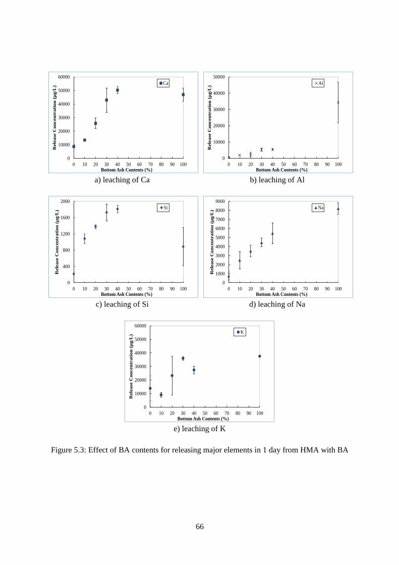
66
a) leaching of Ca
b) leaching of Al
c) leaching of Si
d) leaching of Na
e) leaching of K
Figure 5.3: Effect of BA contents for releasing major elements in 1 day from HMA with BA
0
10000
20000
30000
40000
50000
60000
0 10 20 30 40 50 60 70 80 90 100
Rele
ase
Con
cen
trati
on
(µ
g/L
)
Bottom Ash Contents (%)
Ca
0
10000
20000
30000
40000
50000
0 10 20 30 40 50 60 70 80 90 100
Rele
ase
Con
cen
trati
on
(µ
g/L
)
Bottom Ash Contents (%)
Al
0
400
800
1200
1600
2000
0 10 20 30 40 50 60 70 80 90 100
Rele
ase
Con
cen
trati
on
(µ
g/L
)
Bottom Ash Contents (%)
Si
0
1000
2000
3000
4000
5000
6000
7000
8000
9000
0 10 20 30 40 50 60 70 80 90 100
Rele
ase
Con
cen
trati
on
(µ
g/L
)
Bottom Ash Contents (%)
Na
0
10000
20000
30000
40000
50000
60000
0 10 20 30 40 50 60 70 80 90 100
Rele
ase
Con
cen
trati
on
(µ
g/L
)
Bottom Ash Contents (%)
K

67
a) leaching of Cu
b) leaching of Fe
c) leaching of Mg
d) leaching of Ti
e) leaching of Zn
Figure 5.4: Effect of BA contents for releasing minor elements in 1 day from HMA with BA
0
10
20
30
40
50
60
70
0 10 20 30 40 50 60 70 80 90 100
Rele
ase
Con
cen
trati
on
(µ
g/L
)
Bottom Ash Contents (%)
Cu
0
2
4
6
8
10
0 10 20 30 40 50 60 70 80 90 100
Rele
ase
Con
cen
trati
on
(µ
g/L
)
Bottom Ash Contents (%)
Fe
0
100
200
300
400
500
600
700
800
0 10 20 30 40 50 60 70 80 90 100
Rele
ase
Con
cen
trati
on
(µ
g/L
)
Bottom Ash Contents (%)
Mg
0
0.25
0.5
0.75
1
0 10 20 30 40 50 60 70 80 90 100
Rele
ase
Con
cen
trati
on
(µ
g/L
)
Bottom Ash Contents (%)
Ti
0
2
4
6
8
10
12
0 10 20 30 40 50 60 70 80 90 100
Rele
ase
Con
cen
trati
on
(µ
g/L
)
Bottom Ash Contents (%)
Zn

68
5.2.2.2 Effect of Elapsed Time Exposed to Synthetic Rain Solution
Typically, the concentration of major elements increases with increasing time except
Ca. However, the concentration of minor elements is stable or reduced with increasing time
(see Figure 5.5) which appears to be the characteristics of availability control leaching [2, 33]
where leaching of elements is a function of “availability of leaching”. However, the source of
Ca, Al, Na are from BA itself, whereas, both BA and HMA contribute to the concentration of
K. In addition, higher leaching of Al at low pH condition with the progress of time is
attributed to the characteristics of amphoteric element [2, 33] which exhibits high release
concentration of element both at low and high pH condition.
Ca is out-ranged from detection limit, which shows approximate 50000 µg/L
regardless high contents of BA. High concentration of Ca is believed to be partially
originated from limestone which was used in HMA as coarse aggregate, is predominantly
CaCO3. Limestone disintegrated during the crushing of HMA as the sample preparation for
the leaching test; thus broken limestone aggregate particles were exposed to the acidic
extraction fluid which leads to the high content of Ca leaching with time.
The concentration of minor elements exhibit steady or even reduced leaching trends
with time for the HMA specimens containing 10 and 20% BA (see Figure 5.6). Higher
proportion of BA provides higher content of minor elements available for acid leaching; thus,
with elapsed time minor element leaching increased for the specimens containing 30 and 40
% BA. Acidic pH of the synthetic rain solution over 3 day period cause to lower the pH of the
leachate, thus available elements in the specimens were subject to release over the elapsed
time.

69
a) leaching of Ca
b) leaching of Al
c) leaching of Si
d) leaching of Na
e) Leaching of K
Figure 5.5: Leaching concentration for major elements from BA mixed HMA with respect to
elapsed time
0.0
10,000.0
20,000.0
30,000.0
40,000.0
50,000.0
60,000.0
0.5 1.0 1.5 2.0 2.5 3.0 3.5
Rele
ase
Co
ncen
tra
tion
(µ
g/L
)
Elapsed Time (d)
HMA+ 0% BA
HMA+ 10% BA
HMA+ 20% BA
HMA+ 30% BA
HMA+ 40% BA
BA only
0.0
5,000.0
10,000.0
15,000.0
20,000.0
25,000.0
30,000.0
35,000.0
40,000.0
45,000.0
0.5 1.0 1.5 2.0 2.5 3.0 3.5
Rele
ase
Con
cen
tra
tion
(µ
g/L
)
Elapsed Time (d)
HMA+ 0% BA
HMA+ 10% BA
HMA+ 20% BA
HMA+ 30% BA
HMA+ 40% BA
BA only
0.0
500.0
1,000.0
1,500.0
2,000.0
2,500.0
0.5 1.0 1.5 2.0 2.5 3.0 3.5
Rele
ase
Co
ncen
tra
tion
(µ
g/L
)
Elapsed Time (d)
HMA+ 0% BA
HMA+ 10% BA
HMA+ 20% BA
HMA+ 30% BA
HMA+ 40% BA
BA only
0.0
5,000.0
10,000.0
15,000.0
20,000.0
25,000.0
30,000.0
0.5 1.0 1.5 2.0 2.5 3.0 3.5
Rele
ase
Co
ncen
tra
tion
(µ
g/L
)
Elapsed Time (d)
HMA+ 0% BA
HMA+ 10% BA
HMA+ 20% BA
HMA+ 30% BA
HMA+ 40% BA
BA only
0.0
5,000.0
10,000.0
15,000.0
20,000.0
25,000.0
30,000.0
35,000.0
40,000.0
0.5 1.0 1.5 2.0 2.5 3.0 3.5
Rele
ase
Co
ncen
tra
tion
(µ
g/L
)
Elapsed Time (d)
HMA+ 0% BA
HMA+ 10% BA
HMA+ 20% BA
HMA+ 30% BA
HMA+ 40% BA
BA only

70
a) leaching of Cu
b) leaching of Fe
c) leaching of Mg
d) leaching of Ti
e) leaching of Zn
Figure 5.6: Leaching concentration for minor elements from BA mixed HMA with respect to
elapsed time
1.0
10.0
100.0
0.5 1.0 1.5 2.0 2.5 3.0 3.5
Rele
ase
Co
ncen
tra
tion
(µ
g/L
)
Elapsed Time (d)
HMA+ 0% BA
HMA+ 10% BA
HMA+ 20% BA
HMA+ 30% BA
HMA+ 40% BA
BA only
0.0
1.0
2.0
3.0
4.0
5.0
6.0
0.5 1.0 1.5 2.0 2.5 3.0 3.5
Rele
ase
Co
ncen
tra
tion
(µ
g/L
)
Elapsed Time (d)
HMA+ 0% BA
HMA+ 10% BA
HMA+ 20% BA
HMA+ 30% BA
HMA+ 40% BA
BA only
0.0
100.0
200.0
300.0
400.0
500.0
600.0
0.5 1.0 1.5 2.0 2.5 3.0 3.5
Rele
ase
Co
ncen
tra
tion
(µ
g/L
)
Elapsed Time (d)
HMA+ 0% BA
HMA+ 10% BA
HMA+ 20% BA
HMA+ 30% BA
HMA+ 40% BA
BA only
0.0
0.1
0.2
0.3
0.4
0.5
0.6
0.5 1.0 1.5 2.0 2.5 3.0 3.5
Rele
ase
Co
ncen
tra
tion
(µ
g/L
)
Elapsed Time (d)
HMA+ 0% BA
HMA+ 10% BA
HMA+ 20% BA
HMA+ 30% BA
HMA+ 40% BA
BA only
0.0
1.0
2.0
3.0
4.0
5.0
6.0
7.0
0.5 1.0 1.5 2.0 2.5 3.0 3.5
Rele
ase
Co
ncen
tra
tion
(µ
g/L
)
Elapsed Time (d)
HMA+ 0% BA
HMA+ 10% BA
HMA+ 20% BA
HMA+ 30% BA
HMA+ 40% BA
BA only

71
5.2.2.3 Comparison with Water Quality Regulation
In order to address the potential of contamination from reuse of MSWI ashes,
leaching concentration of elements of interest were compared with the stringent drinking
water standards [63] and more pragmatic Multi-Sector General Permit for Stormwater
Discharges Associated with Industrial Activity, the “2008 MSGP” [150], both of which are
regulated by the U.S. Environmental Protection Agency (U.S. EPA).
Leachate originated from the waste utilization site, can infiltrate in the groundwater
and contaminate the drinking water sources. Drinking water standard includes Maximum
Contaminants Level (MCL) and Secondary Maximum Contaminants Level (SMCL) [63, 64].
MCLs are enforceable standards for the elements directly toxic for health and SMCL are the
non-mandatory standards limiting the elements for aesthetic concern.
Due to the stormwater percolation through the waste application site, runoff can carry
the pollutants from the application site to the receiving water; thereby, contaminate the
nearby waterbodies via storm-sewer system. Therefore, U.S. EPA classified waste
management as an activity at industrial facilities which can be considered as a major source
of pollutants in stormwater [151] and enforced 2008 Multi-Sector General Permit (MSGP) to
regulate the stormwater discharge [150].
MCLs, SMCLs and MSGP benchmarks for different elements of interest are
summarized in Table 5.1. Release concentration of Fe, Zn and Al were compared with
SMCLs and MSGP benchmarks. Although Cu has both MCL and SMCL, more stringent
SMCL and MSGP benchmark value were considered to compare with the leachate
concentration of Cu.

72
Table 5.1: Drinking water standard for elements of interest (µg/L) [63, 64, 150]
Element MCLa
SMCLb
MSGPc
Cu 1300 1000 14000
Fe - 300 1000000
Zn - 5000 120000
Al - 200 750000 aMCL = Maximum Contaminants Level
bSMCL = Secondary Maximum Contaminants Level
cMSGP = Multi-Sector General Permit
The average concentration of Cu, Fe, and Zn from BA and BA-mixed HMA were far
below their corresponding SMCLs (see Figure 5.7. a, b, c). Highest concentration of Cu
found in the BA was in the range of 35 – 45 µg/L which is insignificant compared to SMCL
(1000 µg/L) and MSGP (14000 µg/L). Similarly, Fe concentration was found to be highest in
the only BA specimens. The maximum concentration of Fe did not exceed 6 µg/L whereas
SMCL and MSGP values are 300 µg/L and 1000000 µg/L, respectively. Although the
leaching of Zn from BA is minimal, HMA containing 20% of BA exhibited comparatively
higher extent of leaching in the range of 0.63 – 6.5 µg/L which is well below the SMCL of
5000 µg/L and MSGP of 120000 µg/L.
On the contrary, large amount of Al leaching resulted from BA and HMA containing
BA specimens compared to the SMCL value of 200 µg/L (see Figure 5.7. d). However, Al
leaching is considerably below the MSGP benchmark value of 750000 µg/L. Leaching results
obtained from control specimen (0 % BA) also gives higher Al concentration than the SMCL,
but lower than MSGP limit. The concentration of Al in BA (more than 40000 µg/L) is almost
2 to 3 times higher than those of BA mixed HMA samples (range of 5000 – 14600 µg/L from
HMA containing 30 % BA). However, it is evident that such higher concentration of Al
mostly originated from BA, although HMA contribute to the high leaching of Al.

73
a) leaching of Cu
b) leaching of Fe
c) leaching of Zn
d) leaching of Al
Figure 5.7: Leaching concentration of priority elements from BA mixed HMA compared to
SMCL and MSGP
5.3 Leaching Characteristics of MSWI Bottom Ash in PCC
In this section, leaching behavior has been investigated for concrete specimens
containing different proportion of MSWI BA as partial substitute of fine aggregate. Leaching
concentrations were obtained for the inorganic constituents originated from BA incorporated
in concrete specimen with a different range of particle size.
1.0
10.0
100.0
1,000.0
10,000.0
100,000.0
0.0 0.5 1.0 1.5 2.0 2.5 3.0 3.5Rel
ease
Co
nce
ntr
ati
on
(µ
g/L
)
Elapsed Time (d)
HMA+ 0% BA HMA+ 10% BA
HMA+ 20% BA HMA+ 30% BA
HMA+ 40% BA BA only
SMCL (1000 µg/L)
MSGP (14000 µg/L)
1.0
10.0
100.0
1,000.0
10,000.0
100,000.0
1,000,000.0
10,000,000.0
0.0 0.5 1.0 1.5 2.0 2.5 3.0 3.5Rel
ea
se C
on
cen
tra
tio
n (
µg
/L)
Elapsed Time (d)
HMA+ 0% BA HMA+ 10% BAHMA+ 20% BA HMA+ 30% BAHMA+ 40% BA BA only
SMCL (300 µg/L)
MSGP (1000000 µg/L)
0.1
1
10
100
1000
10000
100000
1000000
0.0 0.5 1.0 1.5 2.0 2.5 3.0 3.5
Rele
ase
Co
ncen
tra
tio
n (
µg
/L)
Elapsed Time (d)
HMA+ 0% BA HMA+ 10% BA
HMA+ 20% BA HMA+ 30% BA
HMA+ 40% BA BA only
SMCL (5000 µg/L)
MSGP (120000 µg/L)
1
10
100
1000
10000
100000
1000000
0.0 0.5 1.0 1.5 2.0 2.5 3.0 3.5
Rele
ase
Con
cen
trati
on
(µ
g/L
)
Elapsed Time (d)
HMA+ 0% BA HMA+ 10% BAHMA+ 20% BA HMA+ 30% BAHMA+ 40% BA BA only
SMCL (200 µg/L)
MSGP (750000 µg/L)
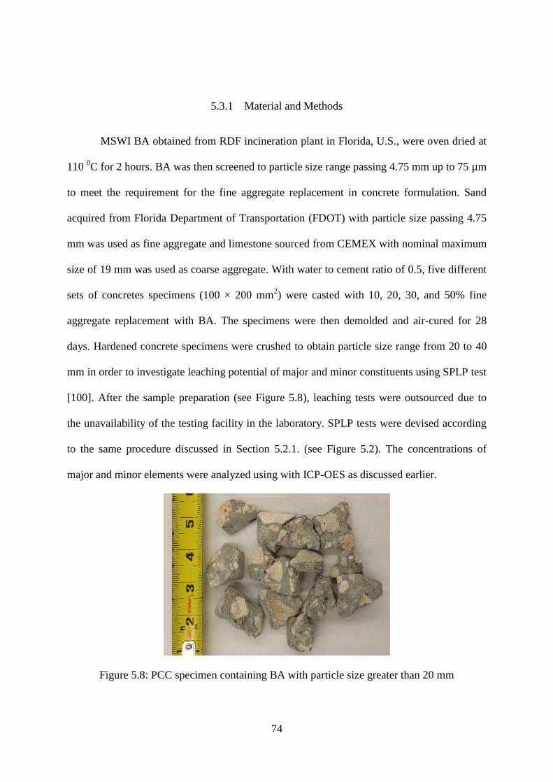
74
5.3.1 Material and Methods
MSWI BA obtained from RDF incineration plant in Florida, U.S., were oven dried at
110 0C for 2 hours. BA was then screened to particle size range passing 4.75 mm up to 75 µm
to meet the requirement for the fine aggregate replacement in concrete formulation. Sand
acquired from Florida Department of Transportation (FDOT) with particle size passing 4.75
mm was used as fine aggregate and limestone sourced from CEMEX with nominal maximum
size of 19 mm was used as coarse aggregate. With water to cement ratio of 0.5, five different
sets of concretes specimens (100 × 200 mm2) were casted with 10, 20, 30, and 50% fine
aggregate replacement with BA. The specimens were then demolded and air-cured for 28
days. Hardened concrete specimens were crushed to obtain particle size range from 20 to 40
mm in order to investigate leaching potential of major and minor constituents using SPLP test
[100]. After the sample preparation (see Figure 5.8), leaching tests were outsourced due to
the unavailability of the testing facility in the laboratory. SPLP tests were devised according
to the same procedure discussed in Section 5.2.1. (see Figure 5.2). The concentrations of
major and minor elements were analyzed using with ICP-OES as discussed earlier.
Figure 5.8: PCC specimen containing BA with particle size greater than 20 mm

75
5.3.2 Leachate Analysis for PCC Containing Bottom Ash
5.3.2.1 Effect of Bottom Ash contents
Batch leaching tests for PCC combined with 10, 20, 30, and 50% of BA were
conducted to examine the effect of BA content on leaching performance. BA without HMA
was also tested as a control specimen to evaluate the leaching potentials from the reuse of BA
in PCC.
For most major element such as Ca, Al, K and Na, which are large portion of
component in PCC with BA in terms of weight, release concentration increases with
increasing BA contents except Si as shown in Figure 5.9. With increasing BA contents, the
major element of BA is more exposed to synthetic rain solution and leachates more.
Significant reduction of the release of Al, Si, and Na were observed due to the incorporation
of BA in PCC as compared to the BA control specimen (see Figure 5.9. b, c, d). Since
Ca(OH)2 is major composition in PCC itself [119, 143], both PCC and BA were responsible
for the Ca release.
However, minor (metal) elements shows different leaching behavior from the major
elements. Generally, minor elements increase with increasing the amount of BA as shown in
Figure 5.10. Unlike the case of the HMA, the PCC impede releasing the element from the BA
in lesser extent. Ca bearing minerals are believed to encapsulate heavy metals into the PCC,
PCC itself contains Fe as an integrated component in the strength building cement matrix
[143], thus higher leaching of Fe from BA-mixed PCC has been observed with compared to
the BA control specimen (see Figure 5.10. b). The leaching concentrations of elements from
PCC containing BA, however, appeared to be lower than the control BA specimen (see

76
Figure 5.9 and 5.10). Replacement of 50% of BA in PCC resulted in significantly increased
leaching for most of the heavy metals.
a) leaching of Ca
b) leaching of Al
c) leaching of Si
d) leaching of Na
e) leaching of K
Figure 5.9: Effect of BA contents for releasing major elements in 1 day from PCC with BA
0
10000
20000
30000
40000
50000
60000
0 10 20 30 40 50 60 70 80 90 100
Rele
ase
Co
ncen
tra
tio
n (
µg
/L)
Bottom Ash Contents (%)
Ca
0
10000
20000
30000
40000
50000
0 10 20 30 40 50 60 70 80 90 100
Rele
ase
Con
cen
tra
tio
n (
µg/L
)Bottom Ash Contents (%)
Al
0
200
400
600
800
1000
1200
1400
0 10 20 30 40 50 60 70 80 90 100
Rele
ase
Co
ncen
tra
tio
n (
µg
/L)
Bottom Ash Contents (%)
Si
0
10000
20000
30000
40000
50000
60000
0 10 20 30 40 50 60 70 80 90 100
Rele
ase
Co
ncen
tra
tio
n (
µg
/L)
Bottom Ash Contents (%)
Na
0
10000
20000
30000
40000
0 10 20 30 40 50 60 70 80 90 100
Rele
ase
Co
ncen
tra
tio
n (
µg
/L)
Bottom Ash Contents (%)
K

77
a) leaching of Cu
b) leaching of Fe
c) leaching of Mg
d) leaching of Ti
e) leaching of Zn
Figure 5.10: Effect of BA contents for releasing minor elements in 1 day from PCC with BA
0
20
40
60
80
100
0 10 20 30 40 50 60 70 80 90 100
Rele
ase
Co
ncen
tra
tio
n (
µg
/L)
Bottom Ash Contents (%)
Cu
0
3
6
9
12
15
18
0 10 20 30 40 50 60 70 80 90 100
Rele
ase
Co
ncen
tra
tio
n (
µg
/L)
Bottom Ash Contents (%)
Fe
0
100
200
300
400
500
600
700
800
0 10 20 30 40 50 60 70 80 90 100
Rele
ase
Co
ncen
tra
tio
n (
µg
/L)
Bottom Ash Contents (%)
Mg
0
0.1
0.2
0.3
0.4
0.5
0 10 20 30 40 50 60 70 80 90 100
Rele
ase
Co
ncen
tra
tio
n (
µg
/L)
Bottom Ash Contents (%)
Ti
0
0.5
1
1.5
2
2.5
3
0 10 20 30 40 50 60 70 80 90 100
Rele
ase
Con
cen
trati
on
(µ
g/L
)
Bottom Ash Contents (%)
Zn

78
5.3.2.2 Effect of Elapsed Time Exposed to Synthetic Rain Water
Typically, the concentration of major elements such as Al and Na increases with
increasing time (see Figure 5.11). These elements were available to leach due to the exposure
to the synthetic rain water. Increasing release of Ca with time from the BA-mixed PCC was
attributed to the Ca(OH)2 dissolution [119] from the PCC matrix due to the acidic pH
condition (Figure 5.11. a). Si showed reduced leaching with the passage of time (Figure 5.11
c). K release appears to be stable with the increasing exposure to acidic rain water (Figure
5.11 e).
Among the minor elements, Cu, Fe, and Zn exhibit significant increase in leaching
with time. Due to the acidic extraction, such increasing trend is observed. The concentrations
of Fe and Zn increase rapidly in 3days due the characteristic feature of amphoteric elements
exposed to acidic synthetic rain water (Figure 5.12. b and e). On the other hand, the
concentrations of Mg and Ti are reduced or fluctuated with time (see Figure 5.12. c and d).

79
a) leaching of Ca
b) leaching of Al
c) leaching of Si
d) leaching of Na
e) Leaching of K
Figure 5.11: Leaching concentration for major elements from BA mixed PCC with respect to
elapsed time
0
10000
20000
30000
40000
50000
60000
0.0 0.5 1.0 1.5 2.0 2.5 3.0 3.5
Rele
ase
Co
ncen
tra
tio
n (
µg
/L)
Time (d)
PCC + 10% BA
PCC + 20% BA
PCC + 30% BA
PCC + 50% BA
BA only0
5000
10000
15000
20000
25000
30000
35000
40000
45000
0.0 0.5 1.0 1.5 2.0 2.5 3.0 3.5
Rele
ase
Co
ncen
tra
tio
n (
µg
/L)
Time (d)
PCC + 10% BAPCC + 20% BAPCC + 30% BAPCC + 50% BABA only
0.0
100.0
200.0
300.0
400.0
500.0
600.0
700.0
800.0
900.0
1,000.0
0.0 0.5 1.0 1.5 2.0 2.5 3.0 3.5
Rel
ease
Con
cen
trat
ion
(µ
g/L
)
Time (d)
PCC + 10% BAPCC + 20% BAPCC + 30% BAPCC + 50% BABA only
0
5000
10000
15000
20000
25000
30000
35000
40000
45000
0.0 0.5 1.0 1.5 2.0 2.5 3.0 3.5
Rel
ease
Co
nce
ntr
ati
on
(µ
g/L
)
Time (d)
PCC + 10% BA
PCC + 20% BA
PCC + 30% BA
PCC + 50% BA
BA only
0
5000
10000
15000
20000
25000
30000
35000
40000
0.0 0.5 1.0 1.5 2.0 2.5 3.0 3.5
Rel
ease
Co
nce
ntr
ati
on (
µg
/L)
Time (d)
PCC + 10% BAPCC + 20% BAPCC + 30% BAPCC + 50% BABA only

80
a) leaching of Cu
b) leaching of Fe
c) leaching of Mg
d) leaching of Ti
e) leaching of Zn
Figure 5.12: Leaching concentration for minor elements from BA mixed PCC with respect to
elapsed time
0.0
5.0
10.0
15.0
20.0
25.0
30.0
35.0
40.0
45.0
50.0
0.0 0.5 1.0 1.5 2.0 2.5 3.0 3.5
Rele
ase
Co
ncen
tra
tio
n (
µg
/L)
Time (d)
PCC + 10% BAPCC + 20% BAPCC + 30% BAPCC + 50% BABA without PCC
0.0
2.0
4.0
6.0
8.0
10.0
12.0
14.0
16.0
18.0
20.0
0.0 0.5 1.0 1.5 2.0 2.5 3.0 3.5
Rele
ase
Co
ncen
tra
tio
n (
µg
/L)
Time (d)
PCC + 10% BA
PCC + 20% BA
PCC + 30% BA
PCC + 50% BA
BA without PCC
0.0
50.0
100.0
150.0
200.0
250.0
300.0
350.0
400.0
450.0
500.0
0.0 0.5 1.0 1.5 2.0 2.5 3.0 3.5
Rel
ease
Co
nce
ntr
ati
on
(µ
g/L
)
Time (d)
PCC + 10% BAPCC + 20% BAPCC + 30% BAPCC + 50% BABA without PCC
0.0
0.1
0.2
0.3
0.4
0.5
0.6
0.0 0.5 1.0 1.5 2.0 2.5 3.0 3.5
Rel
ease
Co
nce
ntr
ati
on
(µ
g/L
)
Time (d)
PCC + 10% BAPCC + 20% BAPCC + 30% BAPCC + 50% BABA without PCC
0.0
2.0
4.0
6.0
8.0
10.0
12.0
14.0
16.0
18.0
20.0
0.0 0.5 1.0 1.5 2.0 2.5 3.0 3.5
Rel
ease
Co
nce
ntr
ati
on
(µ
g/L
)
Time (d)
PCC + 10% BA
PCC + 20% BA
PCC + 30% BA
PCC + 50% BA
BA without PCC

81
5.3.2.3 Comparison with Water Quality Regulation
To investigate the environmental risk associated with application of BA in PCC,
leaching concentration of priority elements from BA-mixed PCC were compared with the
drinking water standards, particularly SMCLs, and stormwater discharge limit, named as
MSGP benchmarks as discussed in Section 5.2.2.3. Leachate concentration of Cu, Fe, Zn and
Al were compared with the corresponding SMCLs and MSGPs (see Figure 5.13).
The average concentration of Cu, Fe, and Zn (except Al) from BA and BA-mixed
PCC were far below the SMCLs (see Figure 5.13). However, release concentration of these
elements (including Al) remains considerably below the MSGPs. Maximum Cu
concentration, found in BA, was in the range of 70.1 - 22.9 µg/L which is minor compared to
the SMCL (1000 µg/L) and MSGP (14000 µg/L). Unlike BA-mixed HMA specimens, BA
combined with PCC, however, did not show significant reduction of Cu and Zn leaching.
Over 3 day period, PCC combined with 50% BA was found to leach 35.56 µg/L of Cu with
compared to 32.26 µg/L of Cu from BA itself.
Leaching of Fe did not improve by the application of BA in PCC, rather leaching of
Fe increased with the addition of PCC. With elapsed time, release of Zn increased
significantly such that BA-combined PCC specimens resulted in higher leaching of Zn
compared to BA specimen. Highest concentration of Zn leaching from 20% BA-mixed PCC
found to be 18.3 µg/L. which is considerably below the SMCL value of 5000 µg/L and
MSGP value of 120000 µg/L. Maximum concentration of Fe was found to be 16.5 µg/L from
the specimen of PCC with 50% BA which is still well below the SMCL (300 µg/L) and
appears insignificant compared to MSGP benchmark value of 1000000 µg/L.
Release of Al from all the specimens including BA itself exceeded the SMCL (200
µg/L), meets the criteria for MSGP limit (750000 µg/L). Unlike the HMA specimens,
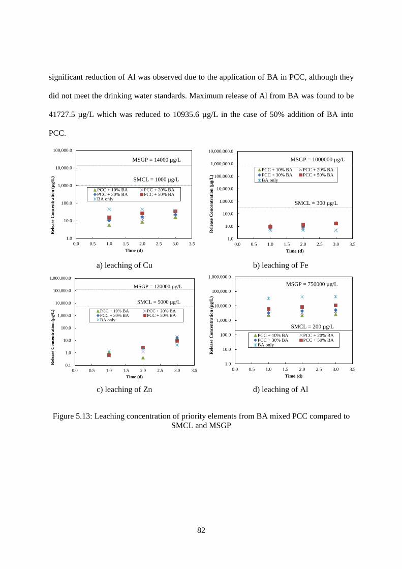
82
significant reduction of Al was observed due to the application of BA in PCC, although they
did not meet the drinking water standards. Maximum release of Al from BA was found to be
41727.5 µg/L which was reduced to 10935.6 µg/L in the case of 50% addition of BA into
PCC.
a) leaching of Cu
b) leaching of Fe
c) leaching of Zn
d) leaching of Al
Figure 5.13: Leaching concentration of priority elements from BA mixed PCC compared to
SMCL and MSGP
1.0
10.0
100.0
1,000.0
10,000.0
100,000.0
0.0 0.5 1.0 1.5 2.0 2.5 3.0 3.5
Rel
ease
Co
nce
ntr
ati
on
(µ
g/L
)
Time (d)
PCC + 10% BA PCC + 20% BAPCC + 30% BA PCC + 50% BABA only
SMCL = 1000 µg/L
MSGP = 14000 µg/L
1.0
10.0
100.0
1,000.0
10,000.0
100,000.0
1,000,000.0
10,000,000.0
0.0 0.5 1.0 1.5 2.0 2.5 3.0 3.5
Rel
ease
Co
nce
ntr
ati
on
(µ
g/L
)
Time (d)
PCC + 10% BA PCC + 20% BAPCC + 30% BA PCC + 50% BABA only
SMCL = 300 µg/L
MSGP = 1000000 µg/L
0.1
1.0
10.0
100.0
1,000.0
10,000.0
100,000.0
1,000,000.0
0.0 0.5 1.0 1.5 2.0 2.5 3.0 3.5
Rel
ease
Co
nce
ntr
ati
on
(µ
g/L
)
Time (d)
PCC + 10% BA PCC + 20% BAPCC + 30% BA PCC + 50% BABA only
SMCL = 5000 µg/L
MSGP = 120000 µg/L
1.0
10.0
100.0
1,000.0
10,000.0
100,000.0
1,000,000.0
0.0 0.5 1.0 1.5 2.0 2.5 3.0 3.5
Rel
ease
Co
nce
ntr
ati
on
(µ
g/L
)
Time (d)
PCC + 10% BA PCC + 20% BAPCC + 30% BA PCC + 50% BABA only
SMCL = 200 µg/L
MSGP = 750000 µg/L

83
5.4 Summary
BA reuse in the HMA matrix appears likely for the significant reduction of heavy
metal release, except for the release of Al. 10 to 20% addition of BA into HMA shows
satisfactory performance to limit the release of heavy metals. HMA facilitates adhesiveness
that aid to encapsulate the trace elements within the HMA. On the other hand, BA
incorporation in PCC appears to be less promising to encapsulate the heavy metals. PCC
specimens, however, demonstrate significant reduction of major elements except Al.
Ineffectiveness to capture heavy metals into PCC matrix can be attributed to the dissolution
of Ca(OH)2 due to the acidic synthetic rain water extraction. Ca bearing such mineral phases
is believed to provide adsorption sites of encapsulation of heavy metals in PCC [33, 118].
SMCLs are associated with aesthetic concern of drinking water quality, thus this limit
criteria appears to be stringent in the context of Al concentration release from the reuse of BA
in HMA and PCC. Moreover, results from acid leaching do not necessarily simulate the field
area of application, especially for this large amount of Al and Ca leaching. Contamination
induced by stormwater infiltration through the waste application site can be considered as
appropriate practical scenario of MSWI utilization. Thus, stormwater discharge limit of
MSGP for the priority pollutants would be more reasonable for utilization of BA. Based on
the latter criteria, leaching from BA-mixed HMA and PCC meets the stormwater discharge
limits. Further leaching investigation is recommended to better simulate the field scenario.
Extensive research study should be warranted for the stabilization and/or removal of major
and minor elements so that BA in HMA and PCC application can be viable with least
leaching potential of heavy metals.

84
CHAPTER 6 PRELIMINARY STUDY OF VITRIFICATION OF
MSWI FLY ASH
6.1 Introduction
Vitrification is one of the most effective techniques to treat hazardous waste materials
to encapsulate toxics into an amorphous glassy matrix. In particular, vitrification of MSWI
FA has been extensively investigated throughout the world [152]. As MSWI ash, in general,
contains significant amount of SiO2, Al2O3 and CaO which are the major ingredient of glass;
thus, it has glass forming capability. It can offer a large reduction in volume up to 80 to 90%
and also provide more environmentally stable and chemically resistant glassy slag which can
be used as secondary material such as road base material, blasting grit, embankments,
pavement bricks and water-permeable blocks [20]. It is demonstrated that dioxin, furan other
toxic compounds are destructed during vitrification above 1400 oC. However, high melting
temperature requires high cost associated with vitrification process and release of
contaminants during melting can be an another potential concern [20]. Therefore, further air
pollution control scheme may be required.
In spite of the reliability of vitrification technology, high cost due to high vitrification
temperature allows this technique only for high toxic waste materials with which
environment is the highest priority [152]. In this chapter, efforts have been made to develop a
concept of an energy-saving vitrification technique of MSWI FA. This chapter summarizes
the scientific background of vitrification, experimental works for MSWI FA vitrification and
future direction for successful vitrification technique with the proof of theoretical concept.
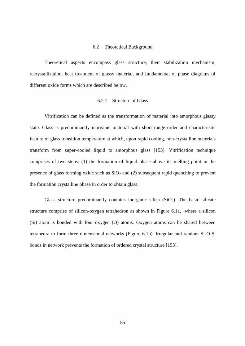
85
6.2 Theoretical Background
Theoretical aspects encompass glass structure, their stabilization mechanism,
recrystallization, heat treatment of glassy material, and fundamental of phase diagrams of
different oxide forms which are described below.
6.2.1 Structure of Glass
Vitrification can be defined as the transformation of material into amorphous glassy
state. Glass is predominantly inorganic material with short range order and characteristic
feature of glass transition temperature at which, upon rapid cooling, non-crystalline materials
transform from super-cooled liquid to amorphous glass [153]. Vitrification technique
comprises of two steps: (1) the formation of liquid phase above its melting point in the
presence of glass forming oxide such as SiO2 and (2) subsequent rapid quenching to prevent
the formation crystalline phase in order to obtain glass.
Glass structure predominantly contains inorganic silica (SiO2). The basic silicate
structure comprise of silicon-oxygen tetrahedron as shown in Figure 6.1a, where a silicon
(Si) atom is bonded with four oxygen (O) atoms. Oxygen atoms can be shared between
tetrahedra to form three dimensional networks (Figure 6.1b). Irregular and random Si-O-Si
bonds in network prevents the formation of ordered crystal structure [153].

86
a) Silicon-Oxygen Tetrahedron
b) Silicate Network
Figure 6.1: Glass Structure. a) Si-O tetrahedron [154], b) random 3D network structure of
glass [155]
In the glass structure, the oxygen covalently bonded with Si is termed as bridging
oxygen while the bond is between Si and O. When other elements are present in the glassy
structure, for instance, sodium making bond with O ionically, interrupts the network
continuity. Oxygen thus bonded ionically with other elements is called non-bridging oxygen.
Some elements can replace Si in the glass network and make covalent bond with O are
denoted as Network Former (NF) and elements those create ionic bond with O are known as
Network Modifier (NM). Here is a list of elements acting as NF and NM in the Table 6.1.
Alkali metals typically act as modifier. Aluminum may be a network former and sometimes
modifier depending upon the alkali contents in the glass, thus is called intermediate. The role
of iron depends on redox condition or oxygen availability on the molten material. For
example, Fe(III) is a network former [156].

87
Table 6.1: Role of different elements in glassy structure [156]
Glass Former Intermediates Glass Modifier
Boron (B) Aluminum (Al) Zinc (Zn)
Silicon (Si) Lead (Pb) Barium (Ba)
Phosphorus (P) Zinc (Zn) Calcium (Ca)
Vanadium (V) Beryllium (Be) Sodium (Na)
Arsenic (As) Potassium (K)
Antimony (Sb)
Germanium (Ge)
6.2.2 Stabilization Mechanisms
Stabilization mechanism for different elements in glassy network can be
accomplished by chemical bonding: a) covalent bond, replace silicon, network former and b)
ionic bond, bond with oxygen, network modifier; and another mechanism is encapsulation of
the inorganic materials by surrounding molten phase and then cooled to glassy phase. In
order to keep the integrity of the glass structure, network former is more involved rather than
network modifier. To reduce the melting temperature of silica, alkali oxides are added which
is again associated with the problem of decreasing durability and increasing leaching
potential [2]. Presence of alkali and earth alkali metals oxides increases the O to NF ratio
produced singly bonded oxygen, breaks up glass network that result in less durable glassy
phase with slightly inferior leaching potential. In order to compensate the structural integrity
issue, Al2O3, Fe2O3 addition would be beneficial to increase durability along with an increase
with melting temperature of material and crystal formation in glassy matrix. Thus, proper
understanding and knowledge of the roles of different oxides in the glass formation is
warranted. It is necessary to optimize the addition of materials for the vitrification of MSWI
FA so that reasonable decrease in melting temperature with increased strength of the product
and improved leaching behavior can be obtained. Table 6.2 shows a list of different oxides
and their roles in glass processing [156].

88
Table 6.2: Effect of oxide addition in glassy matrix [156]
oxides Roles in glass processing
viscosity waste solubility tendency to
crystallize
durability
SiO2 increase greatly reduces increase
B2O3 reduce increase slightly increase
Na2O reduce increase reduce
Li2O reduce greatly increase slightly reduce
K2O reduce increase increase reduce greatly
CaO increase then reduce increase then reduce
MgO increase then reduce increase increase then reduce
TiO2 slightly reduce increase then reduce increase increase
Al2O3 increase increase increase
Fe2O3 reduce reduce greatly increase
NiO reduce greatly increase increase
MnO reduce greatly increase
6.2.3 Devitrification/Recrystallization: Heat Treatment Analysis
In general, vitrification is followed by crystallization, either by cooling from the melt
or by controlled secondary heat treatment for the formation of crystalline phases within
glassy matrix. Controlled crystallization involves two stages of heat treatment, such as,
nucleation and crystallization stages, within a certain glass composition range [147, 157,
158]. Small nuclei are formed during the nucleation stage and after the stabilization of nuclei,
growth of crystalline phase results in crystallization in latter stage. Proper understanding of
nucleation and crystallization is necessary to achieve desired microstructure and properties of
derived glass-ceramic. During the formation of glass ceramic from MSWI FA, nucleating
agents (Fe2O3, TiO2) are present and sometimes reported to be added in the initially formed
glass systems [73, 147] to facilitate crystallization.
Controlled recrystallization or divitrification are employed for the production of glass-
ceramics which are characterized with better physical, mechanical and chemical durability.
Glass-ceramic are fine grained polycrystalline materials derived when glasses at suitable

89
composition are undergone heat treatment to obtain controlled crystallization with lower
stable energy state. Formation of long range ordered crystals from liquid or solid phase
following two steps nucleation and crystal growth is termed as crystallization [153, 157].
During nucleation, structural lattice of atoms, ions or molecules spontaneously organize
themselves as cluster of a characteristic crystal structure. Being thermodynamically stable by
reaching a critical cluster size of few nanometers, nuclei start to growth as a subsequent stage
of crystal growth with a definite order. This technique of crystallization is termed as heat
treatment. Another means of densification of glass –ceramic is sintering which involves the
heating of powdered glass below the melting point to allow the diffusion across grain
boundary and fusing to each other to facilitate denser product with improved properties.
Sintering process is governed by surface crystallization whereas heat treatment is mostly by
bulk crystallization [72, 157].
Based on the composition of raw material, nucleation and crystal growth are
associated with characteristic temperatures which are required to obtain precisely using
Differential Thermal Analysis (DTA) or Differential Scanning Calorimetry (DSC). Key
terminology of those temperatures is described below.
Tg (glass transition temperature): It is a temperature below which the physical
properties of amorphous materials behave like glassy state, and above which
amorphous materials behave like liquids. It is also the mid-point of a temperature
range (usually at 600–700 °C) in which the materials gradually become more viscous
and change from being liquid to solid.
Tc (crystallization temperature): Above this temperature, a crystallization process
consisting nucleation followed by crystal growth. During this process, a sharp

90
exothermic peak (usually between 700 and 800 °C) on the DSC figure could be clearly
observed.
Tm (melting temperature): Liquid temperature is the temperature at which the
specimen changes from solid to liquid state. It represents the temperature for the
dissolution or melting of crystals, and is usually above 1200 °C.
Typical DSC or DTA analysis is shown in Figure 6.2, the plot of heat flow of the
material against the temperature that produces characteristic exothermic peaks of
crystallization and endothermic peak of glass transition and melting temperature. In general,
there is another exothermic peak (not sharp) that correspond to nucleation temperature in
between Tg and Tc.
Figure 6.2: Typical heat flow pattern obtained from DSC analysis showing characteristic
peaks of glass transition temperature (Tg), crystallization temperature (Tc) and melting
temperature (Tm) [159]
According to the DSC or DTA analysis, the parent glass is then heated at the
maximum nucleation temperature and then heated to a higher temperature which refers to

91
crystallization temperature for a certain time for each step, and finally it is allowed to cool to
develop glass ceramic. Microcrystalline glass-ceramics are produced by extensive nucleation
containing higher number of nuclei are significantly mechanically superior [76]. In the case
devitrified MSWI FA, most crystalline phases appears after heat treatment and sintering are
reported to be gelhlenite (2.CaO.SiO2.Al2O3), wollastonite (CaSiO3), and other silicate and
alumino-silicate phases (pyroexen groups) as observed by previous researchers [66, 72, 74,
76, 79, 80].
6.2.4 Phases Diagrams in Glass Formation of MSWI Fly Ash
MSWI FA, in general, belongs to SiO2-CaO-Al2O3 system based on its compositions.
This chemical system is termed as ternary phase diagram which is originated and constructed
from three binary phase diagram systems [153] as shown in the Figure 6.3. These phase
diagrams facilitate information regarding relative composition of components in a particular
phase at a certain temperature.
Another important feature of phase diagram is Eutectic point. A eutectic system is a
mixture of chemical compounds or elements that has a single chemical composition that
solidifies at a lower temperature than any other composition. This composition is known as
the eutectic composition and the temperature is known as the eutectic temperature. The
eutectic point can be seen in the Figure 6.4 for a hypothetical A-B binary phase system.

92
a. SiO2-Al2O3 phase diagram [160]
b. SiO2-CaO phase diagram [161]
c. Al2O3-CaO phase diagram [162]
Figure 6.3: Binary phase diagrams correspond to glass and glass ceramic from MSWI FA
Figure 6.4: Hypothetical binary phase diagram showing eutectic point

93
SiO2-Al2O3, SiO2-CaO, and Al2O3-CaO binary systems (Figure 6.3) can be utilized to
form ternary phase of SiO2-CaO-Al2O3 system as shown in Figure 6.5. This represents the
phases present during the glass transformation of MSWI FA, in general. In the Figure 6.5, the
eutectic composition in the ternary system has been found to be 23.25 wt% CaO, 14.75 wt%
Al2O3, 62 wt% SiO2 at lowest melting temperature of 1170 0C.
Figure 6.5: SiO2-CaO-Al2O3 ternary phase diagram [163]
Figure 6.5 shows that, of all possible mixtures of minerals made only of calcium,
aluminum, silicon and oxygen: anorthite (calcium feldspar), quartz and wollastonite, will
melt at precisely 1170°C. MSWI FA composition falls under the dark circle zone of the
Figure 6.5. Therefore, it is required to add other oxides in proper proportion with FA to
obtain theoretical eutectic composition that correspond to minimum melting temperature at
eutectic point.

94
Based on the waste composition of SiO2, CaO and Al2O3 of particular MSWI FA and
melting temperature obtained from DTA or DSC analysis, it is possible to locate the position
of that sample within this ternary diagram that will further give the idea about the crystalline
characteristics and microstructure of resultant glass derived ceramics. This theoretical
information can further be investigated for the thorough characterization of vitrified ash in
terms of their chemical durability which is closely tied with the improved leaching behavior.
This is an important issue for the use of vitrified ash in the context of environmental point of
view.
6.3 Experimental Works
Experimental strategies have been devised for the vitrification of MSWI FA based on
the theoretical aspects of glass structure, their stabilization mechanisms, and heat treatment
scheme along with the aid of fundamental phase diagrams of different oxide compounds
which are discussed below.
As discussed in Chapter 4, MSWI FA was obtained from a RDF plant in Florida. The
RDF facility preprocesses raw MSWs with shredding and metal removal prior to the
combustion; thus, feeding wastes become smaller size and more homogeneous for more
effective combustion. After the combustion, FA goes to an APC device where lime-scrubber
treatments are applied to the FA for reducing the acid gases. Thus, the FA characterized in
this study is technically APC residues but referred as FA as a general term.
The experimental work focused on characterization of derived glass and crystallized
glass-ceramic phases. Previous researchers have utilized glass-forming materials such as,
silica, iron waste, alumina waste, and glass cullet for the MSWI FA to obtain desired and
suitable composition for making glass [72-74]. During the glass formation, quenching was
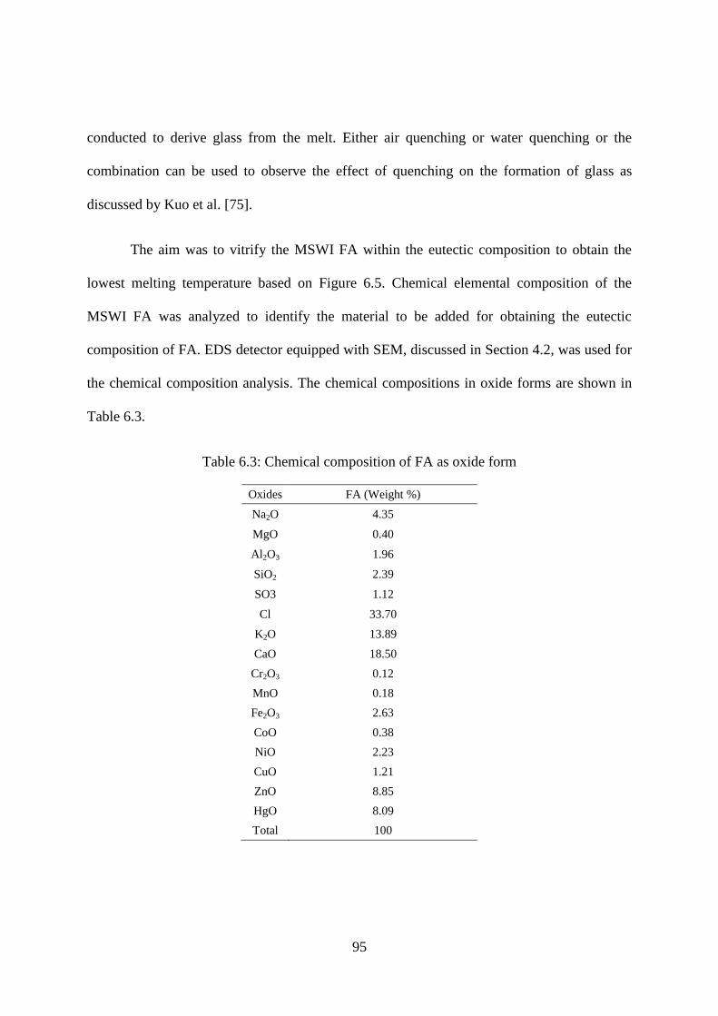
95
conducted to derive glass from the melt. Either air quenching or water quenching or the
combination can be used to observe the effect of quenching on the formation of glass as
discussed by Kuo et al. [75].
The aim was to vitrify the MSWI FA within the eutectic composition to obtain the
lowest melting temperature based on Figure 6.5. Chemical elemental composition of the
MSWI FA was analyzed to identify the material to be added for obtaining the eutectic
composition of FA. EDS detector equipped with SEM, discussed in Section 4.2, was used for
the chemical composition analysis. The chemical compositions in oxide forms are shown in
Table 6.3.
Table 6.3: Chemical composition of FA as oxide form
Oxides FA (Weight %)
Na2O 4.35
MgO 0.40
Al2O3 1.96
SiO2 2.39
SO3 1.12
Cl 33.70
K2O 13.89
CaO 18.50
Cr2O3 0.12
MnO 0.18
Fe2O3 2.63
CoO 0.38
NiO 2.23
CuO 1.21
ZnO 8.85
HgO 8.09
Total 100
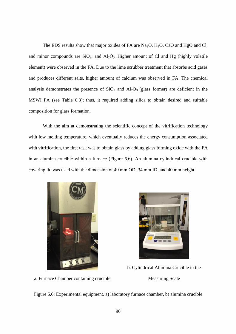
96
The EDS results show that major oxides of FA are Na2O, K2O, CaO and HgO and Cl,
and minor compounds are SiO2, and Al2O3. Higher amount of Cl and Hg (highly volatile
element) were observed in the FA. Due to the lime scrubber treatment that absorbs acid gases
and produces different salts, higher amount of calcium was observed in FA. The chemical
analysis demonstrates the presence of SiO2 and Al2O3 (glass former) are deficient in the
MSWI FA (see Table 6.3); thus, it required adding silica to obtain desired and suitable
composition for glass formation.
With the aim at demonstrating the scientific concept of the vitrification technology
with low melting temperature, which eventually reduces the energy consumption associated
with vitrification, the first task was to obtain glass by adding glass forming oxide with the FA
in an alumina crucible within a furnace (Figure 6.6). An alumina cylindrical crucible with
covering lid was used with the dimension of 40 mm OD, 34 mm ID, and 40 mm height.
a. Furnace Chamber containing crucible
b. Cylindrical Alumina Crucible in the
Measuring Scale
Figure 6.6: Experimental equipment. a) laboratory furnace chamber, b) alumina crucible

97
In the laboratory furnace, 5 gram of the FA was placed in the alumina crucible with
the lid and it was mixed with 2.3 gram of amorphous silica powder as shown in Figure 6.7 a.
Amorphous silica powder with 0.2-μm particle size was purchased from Geltech, Inc. The
amount of silica to be added was determined in order to meet the requirement for the eutectic
composition as discussed in Figure 6.5. The mixed powder was then placed in the alumina
crucible with the lid, and heat-treated at 800 0C for 1 hour, followed by melting in a
laboratory furnace at 1200 0C for 1 hour. After air quenching, the final product appeared to be
glassy as seen in the Figure 6.7 b.
a) FA with silica before melting
b) FA with silica after melting
Figure 6.7: Vitrification of FA. a) FA mixed with silica before melting, and b) FA with silica
melting at 1200 °C with 1 hour holding time.
In order to determine the mass loss, weight before and after the vitrification was
measured. Mass loss calculation is summarized in Table 6.4. Mass loss due to evaporation
appeared to be negligible.

98
Table 6.4: Mass loss calculation for vitrification of FA
Initial mass:
Crucible + lid + 5 gram
of FA + 2.3 gm of Silica
Intermediate mass:
After 800 °C heating with
1 hour holding time
Final mass:
After melting at 1200 °C
with 1 hour holding time
Mass, gm 91.5149 90.3023 89.3081
Mass loss, % - 1.33 2.4
6.4 XRD Analysis
Rigaku X-ray diffractometer with CuKα radiation, 2θ scanning from 5 to 80º with 0.05º
step size and 3 second dwell time per step was conducted for the vitrified silica-mixed FA
sample. The XRD result for the vitrified FA is presented in Figure 6.8 and major phases in as
received FA and vitrified FA from XRD results are summarized in Table 6.5.
Figure 6.8: X-ray diffraction pattern for the vitrified MSWI FA
Table 6.5: Major phases in the ‘as received’ FA and the vitrified FA
Major Phases in as received FA Major Phases in vitrified FA
Halite (NaCl) Sodium oxide (Na2O)
Sylvite (KCl) Silica (SiO2)
Calcium Chloride Hydroxide Hydrate (CaCl2.Ca(OH)2.2H2O) Calcium Oxide (CaO)
Calcium Sulphate (CaSO4)
Calcite (CaCO3)
0 10 20 30 40 50 60 70 802 Theta
Vitrified FA with
Silica_1200 C
2
3
2
13
1. SiO2
2. Na2O
3. CaO
3
1
2

99
In spite of the exhibiting characteristic amorphous structure of glass, XRD pattern of
the vitrified FA (Figure 6.8) shows major crystalline peaks which are associated with mostly
stable oxide forms; Sodium oxide (Na2O), Silica (SiO2) and Calcium Oxide (CaO). In
contrast, major phases in the XRD pattern of ‘as received’ FA are Halite (NaCl), Sylvite
(KCl) and Calcium Chloride Hydroxide Hydrate (CaCl2.Ca(OH)2.2H2O) as discussed in
Section 4.5 (Figure 4.7) and Table 6.5. During melting, unstable compounds in the FA have
been transformed into chemically more stable oxide forms and there were the evaporation of
NaCl and KCl and dissociation of CaCl2.Ca(OH)2.2H2O at high temperature. This is in
agreement with other researcher’s work which revealed that NaCl and KCl in FA are
evaporated at 804 and 779 °C and CaCl2.Ca(OH)2.2H2O is dissociated to remove chlorides at
689 °C [66]. The XRD analysis also supports the EDS results as shown in Table 6.3. Since
Mercury oxide (HgO) transform to highly volatile elemental mercury (Hg) at high
temperature [148], any significant peak was not evident in XRD data of the vitrified FA.
Although, this preliminary experimentation did not result in effective glass formation of
MSWI FA, it appeared to be promising by the evidence of the formation of more stable
chemical forms of FA after vitrification with the aid of glass forming oxide of silica.
6.5 Recommended Future Research
Future work for the successful vitrification of MSWI FA is recommended, which is
further investigations of making glass with FA and corresponding temperature behavior with
the addition of other oxides using thermal analysis tool, such as, DTA or DSC as described in
the previous section. A proof-of-concept test is proposed and each task is presented as
followed.

100
1) Pure oxides to form glass
MSWI FA, in general, possesses SiO2-CaO-Al2O3 system as discussed in the previous
section. From the ternary phase diagram (Figure 6.5), an eutectic point refers to the lowest
melting temperature of 1170 0C with composition of 23.25 wt. % CaO, 14.75 wt. % Al2O3, 62
wt. % SiO2. Glass will be prepared using these compositions of glass forming oxides. Prior to
the vitrification, ball milling may be necessary to reduce and control the particle size
distribution throughout the sample. This is widely practiced in glass-ceramic industry to
make more homogeneous material for further vitrification and processing [164]. The thermal
analysis can be conducted by using the DSC or DTA to obtain featured temperatures
associated with vitrification and subsequent crystallization; thus, the theoretical melting
temperature shown in the ternary phase diagram (see Figure 6.5) is confirmed.
2) Adding other oxides to lower the melting points
Secondly, the research work will be aimed at reducing the melting temperature of glass.
Table 6.2 demonstrates the effect of presence of different oxides within the glassy matrix.
From this perspective, alkali oxide, for instance, K2O can be added with the glass forming
oxide powders to form glass. The DSC analysis can be then conducted to determine the effect
of addition of alkali oxide regarding the melting temperature of the sample.
3) Adding oxides to make it more durable
Since addition of alkali oxide reduces the durability of glass (see Table 6.2), the proposed
third task is associated with further addition of other oxide that can improve the durability of
glass. In this case, Fe2O3 can be added to enhance the durability of vitrified glass; however,

101
addition of Fe2O3 may slightly increase the melting temperature of the sample which can be
observed by DSC analysis.

102
CHAPTER 7 CONCLUSION AND RECOMMENDATION
7.1 Conclusion
Many countries, especially European and Asian countries, have already successfully
implemented systematic approach towards beneficial utilization of municipal solid waste
incineration (MSWI) ashes in civil construction sectors. MSWI bottom ash (BA), in general,
has been utilized in the area of asphalt, road paving, and concrete products. Due to higher
content of deleterious elements, MSWI fly ash (FA) is mostly disposed in the landfill after
stabilization treatments. Successful recycling programs are being enforced in different
countries so as to encourage the beneficial use of MSWI ashes with minimum environmental
consequence.
Although research and demonstration projects ensure the beneficial utilization of
MSWI ashes as a feasible option, currently there is no recycling of the ashes in the U.S. The
current practice of the U.S. combines MSWI BA and FA, and the combined ashes are being
disposed in landfills. This may be due to the statewide inconsistency in ash management,
regulations, and standard leaching test procedures of the MSWI ash. In addition, debates
regarding highly soluble salt content and heavy metal concentration in MSWI ashes further
discourage its utilization.
Microstructural evaluation of MSWI ashes through SEM analysis reveals that FA
possess more internal porosity and exhibits irregular and angular morphology in comparison
to those of BA. This can be attributed to reduced workability of FA being used in asphalt and
concrete mixtures and also increase of leaching susceptibility.
Based on compositional and mineralogical analysis by EDS and XRD, respectively,
BA appears to contain higher amount of strength-building components (e.g. silica rich) than

103
FA, and FA mostly contains highly soluble salts, Cl, and heavy metals, which needed to be
treated prior to utilization.
Metallic Al appears to be present in BA and FA based on the chemistry laboratory
experiment. It demonstrates the evolution of hydrogen gas due to the metallic Al in both
ashes, which is very small amount and was not detected in the XRD analysis. According to
the back-calculation from the hydrogen gas measurement, both BA and FA contain
approximately 0.03% of Al by weight. The presence of Al leads to the inferior performance
of concrete product due to the hydrogen gas evolution produced as a result of hydrolysis of
Al in highly alkaline environment.
Since highly soluble inorganic salts, Cl compounds, and heavy metals were mostly
found from MSWI FA, the utilization of MSWI BA or combined ash (mixture of BA and FA)
might be a potential candidate with reduced probability of deterioration. Among several
options to reuse MSWI ashes, incorporating the MSWI bottom and combined ashes into hot-
mix asphalt (HMA) and Portland cement concrete (PCC) are appears to be encouraging
option because these can result in significant reduction of the release of toxic elements as
well as sufficient level of structural integrity.
Standard leaching experiments have been conducted to investigate the environmental
properties (e.g. leachate concentration of inorganic major and minor elements) of BA and
ash-mixed HMA and PCC. Leaching results reveals the reduced leaching potential of toxic
material from MSWI ashes while being incorporated into asphalt and concrete formulation.
Release of most of the toxic elements of interest (except Al) meets the drinking water
standards. However, leaching of all of the priority elements (including Al) are well below the
stormwater runoff discharge limit.

104
As a means of advance technique to stabilize FA, vitrification appears to be a
promising technique in terms of encapsulating toxic elements in glassy matrix. Preliminary
study on FA vitrification demonstrates the formation of more stable form of mineral phases in
fly while vitrified with the aid of glass forming compounds.
7.2 Recommendation
Weathering and proper pretreatment are highly advised prior to the utilization of
MSWI ashes that can reduce the deleterious substances. Extensive research efforts should be
made for the development of material processing technology to make the utilization of treated
MSWI ashes as a promising option for a sustainable transportation material.
In order to utilize MSWI BA as aggregate replacement in concrete application,
appropriate chemical treatment is warranted to eliminate metallic Al which produces
hydrogen gas causing inferior properties of MSWI ash amended products.
Mechanical and environmental properties are required to be investigated thoroughly
to obtain the optimum % replacement of MSWI ashes in asphalt and concrete in order to
ensure desirable engineering performance and minimum environmental impact.
Further leaching experiments which can better represent the field condition is the
context of release of Al should be devised. Effective technique of the stabilization or removal
of the major and minor elements of concern is also essential in order to make BA utilization a
sustainable one from environmental perspective. Besides, more relevant limit criteria should
be designed that can appropriately represent the environmental consequences of BA
utilization.
Extensive research needs to be conducted for the further study on vitrification of FA
which demonstrates excellent leaching reduction. Since vitrification is a cost intensive and

105
energy consuming thermal technology, efforts are required to make this technique more
economic by lowering the melting temperature by adding appropriate compounds based on
glass chemistry. Glass ceramic products are merited with higher physical integrity, thus,
experimental works should be planned to make glass ceramic from FA vitrification which
will eventually enhance the potential of utilization of vitrified FA.

106
REFERENCES
1. Wiles, C.C., Municipal Solid Waste Combustion Ash: State-of-the-Knowledge.
Journal of Hazardous Materials, 1996. 47(1–3): p. 325-344.
2. Chandler, A.J., T.T. Eighmy, J. Hartlén, Helmar, O., D.S. Kosson, S.E. Sawell, H.A.
van der Sloot, and J. Vehlow, Municipal Solid Waste Incinerator Residues. Studies in
Environmental Science 67. 1997, Amsterdam, the Netherlands: Elsevier.
3. Wiles, C. and P. Shepherd, Beneficial Use and Recycling of Municipal Waste
Combustion Residues -A Comprehensive Resource Document. 1999, National
Renewable Energy Laboratory (NREL): Boulder, CO.
4. Management of Bottom Ash from WTE Plant. 2006, Working Group on Thermal
Treatment of Waste, The International Solid Waste Association (ISWA).
5. Management of APC residues from W-t-E Plants. 2008, Working Group on Thermal
Treatment of Waste, International Solid Waste Association (ISWA).
6. Psomopoulos, C.S., A. Bourka, and N.J. Themelis, Waste-to-Energy: A Review of the
Status and Benefits in USA. Waste Management, 2009. 29(5): p. 1718-1724.
7. Hasselriis, F., Waste-to-Energy Ash Management in the United States, in
Encyclopedia of Sustainability Science and Technology. 2012, Springer: NY. p.
11737-11758.
8. Vehlow, J., Waste-to-Energy Ash Management in Europe, in Encyclopedia of
Sustainability Science and Technology. 2012, Springer: NY. p. 11720-11736.
9. Environmental Data. 2007, The Organisation for Economic Co-operation and
Development (OECD).

107
10. Municipal Solid Waste Generation, Recycling, and Disposal in the United States:
Facts and Figures for 2012. 2012 U.S. Environmental Protection Agency (U.S. EPA),
Washington DC.
11. Michaels, T., The 2010 ERC Directory of Waste-to-Energy Plants. 2010.
12. U.S.EPA, Inventory of U.S. Greenhouse Gas Emissions and Sinks: 1990-2010. 2012.
13. Millrath, K., F.J. Roethel, and D.M. Kargbo. Waste-To-Energy Residues - The Search
for Beneficial Uses. in 12th North American Waste To Energy Conference (NAWTEC
12). 2004. Savannah, GA.
14. Incineration and Thermal Conversion. International Environmental Technology
Centre [cited 2014 June 13]; Available from:
http://www.unep.or.jp/ietc/publications/spc/solid_waste_management/Vol_I/19-
Chapter13.pdf.
15. Tillman, D.A., A.J. Rossi, and K.M. Vick, Incineration of Municipal and Hazardous
Solid Wastes. 1989, San Diego, California: Academic Press, Inc.
16. Speiser, C., T. Baumann, and R. Niessner, Morphological and Chemical
Characterization of Calcium-Hydrate Phases Formed in Alteration Processes of
Deposited Municipal Solid Waste Incinerator Bottom Ash. Environmental Science &
Technology, 2000. 34(23): p. 5030-5037.
17. Qiao, X.C., M. Tyrer, C.S. Poon, and C.R. Cheeseman, Novel Cementitious Materials
Produced from Incinerator Bottom Ash. Resources, Conservation and Recycling,
2008. 52(3): p. 496-510.
18. Bayuseno, A.P. and W.W. Schmahl, Understanding the Chemical and Mineralogical
Properties of the Inorganic Portion of MSWI Bottom Ash. Waste Management, 2010.
30(8–9): p. 1509-1520.

108
19. Wei, Y., T. Shimaoka, A. Saffarzadeh, and F. Takahashi, Mineralogical
Characterization of Municipal Solid Waste Incineration Bottom Ash with an
Emphasis on Heavy Metal-bearing Phases. Journal of Hazardous Materials, 2011.
187(1–3): p. 534-543.
20. Lam, G.H.K., A.W.M. Ip, J.P. Barford, and G. McKay, Use of Incineration MSW
Ash: A Review. Sustainability, 2010. 2: p. 1943-1968.
21. Bertolini, L., M. Carsana, D. Cassago, A. Quadrio Curzio, and M. Collepardi, MSWI
Ashes as Mineral Additions in Concrete. Cement and Concrete Research, 2004.
34(10): p. 1899-1906.
22. Müller, U. and K. Rübner, The Microstructure of Concrete Made with Municipal
Waste Incinerator Bottom Ash as an Aggregate Component. Cement and Concrete
Research, 2006. 36(8): p. 1434-1443.
23. Siddique, R., Use of Municipal Solid Waste Ash in Concrete. Resources, Conservation
and Recycling, 2010. 55(2): p. 83-91.
24. Grosso, M., L. Biganzoli, and L. Rigamonti, A Quantitative Estimate of Potential
Aluminium Recovery from Incineration Bottom Ashes. Resources, Conservation and
Recycling, 2011. 55(12): p. 1178-1184.
25. Biganzoli, L., A. Ilyas, M.v. Praagh, K.M. Persson, and M. Grosso, Aluminium
Recovery vs. Hydrogen Production as Resource Recovery Options for Fine MSWI
Bottom Ash Fraction. Waste Management, 2013. 33(5): p. 1174-1181.
26. Arickx, S., T. Van Gerven, and C. Vandecasteele, Accelerated Carbonation for
Treatment of MSWI Bottom Ash. Journal of Hazardous Materials, 2006. 137(1): p.
235-243.

109
27. Rendek, E., G. Ducom, and P. Germain, Carbon Dioxide Sequestration in Municipal
Solid Waste Incinerator (MSWI) Bottom Ash. Journal of Hazardous Materials, 2006.
128(1): p. 73-79.
28. Arickx, S., V. De Borger, T. Van Gerven, and C. Vandecasteele, Effect of
Carbonation on the Leaching of Organic Carbon and of Copper from MSWI Bottom
Ash. Waste Management, 2010. 30(7): p. 1296-1302.
29. Baciocchi, R., G. Costa, E. Lategano, C. Marini, A. Polettini, R. Pomi, P. Postorino,
and S. Rocca, Accelerated Carbonation of Different Size Fractions of Bottom Ash
from RDF Incineration. Waste Management, 2010. 30(7): p. 1310-1317.
30. Santos, R.M., G. Mertens, M. Salman, Ö. Cizer, and T. Van Gerven, Comparative
Study of Ageing, Heat Treatment and Accelerated Carbonation for Stabilization of
Municipal Solid Waste Incineration Bottom Ash in View of Reducing Regulated
Heavy Metal/Metalloid Leaching. Journal of Environmental Management, 2013.
128(0): p. 807-821.
31. Integrated Pollution Prevention and Control: Reference Document on the Best
Available Techniques for Waste Incineration. 2006, European Commission (EC).
32. Alhassan, H.M. and A.M. Tanko, Characterization of Solid Waste Incinerator Bottom
Ash and the Potential for its Use. International Journal of Engineering Research and
Applications (IJERA), 2012. 2(4): p. 516-522.
33. Sabbas, T., A. Polettini, R. Pomi, T. Astrup, O. Hjelmar, P. Mostbauer, G. Cappai, G.
Magel, S. Salhofer, C. Speiser, et al., Management of Municipal Solid Waste
Incineration Residues. Waste Management, 2003. 23(1): p. 61-88.

110
34. Penque, A., Examination of Chlorides in Municipal Solid Waste to Energy
Combustion Residue: Origins, Fate and Potential for Treatment. 2007, Columbia
University: NY.
35. Aubert, J.E., B. Husson, and A. Vaquier, Metallic Aluminum in MSWI Fly Ash:
Quantification and Influence on the Properties of Cement-based Products. Waste
Management, 2004. 24(6): p. 589-596.
36. Aubert, J.E., B. Husson, and N. Sarramone, Utilization of Municipal Solid Waste
Incineration (MSWI) Fly Ash in Blended Cement: Part 1: Processing and
Characterization of MSWI Fly Ash. Journal of Hazardous Materials, 2006. 136(3): p.
624-631.
37. Aubert, J.E., B. Husson, and N. Sarramone, Utilization of Municipal Solid Waste
Incineration (MSWI) Fly Ash in Blended Cement: Part 2. Mechanical Strength of
Mortars and Environmental Impact. Journal of Hazardous Materials, 2007. 146(1–2):
p. 12-19.
38. 2012 Country Reports on Waste Management. Confederation of European Waste-to-
Energy Plants (CEWEP) [cited 2013 July 30]; Available from:
http://www.cewep.eu/information/data/subdir/index.html.
39. Haaren, R.T., N and Goldstein, N., The State of Garbage in America. 2010, Biocycle.
p. 16-23
40. Sakai, S. and M. Hiraoka, Municipal Solid Waste Incinerator Residue Recycling by
Thermal Processes. Waste Management, 2000. 20(2–3): p. 249-258.
41. Kaufman, S.M., N. Goldstein, K. Millrath, and N.J. Themelis, The State of Garbage
in America, in BioCycle. 2004. p. 31–41.

111
42. Yoshida, F., Case Studies of Environmental Politics in Japan, in Environmental
Policy In Japan. 2005, Edward Elgar: Cheltenham, UK. p. 185–214.
43. Cosentino, P.J., Kalajian, E.H., Heck, H.H. and Shieh, C.S., Developing Specification
for Waste Glass, Municipal Waste Combustor Ash and Waste Tires as Highway Fill
Materials. Volume 1 of 3 (Municipal Waste Combustor Ash). 1995, Florida
Department of Transportation, FL.
44. Shieh, C.D., Managing Florida’s Municipal Waste Combustor Ash: Evaluation of
Leaching Tests and Development of Utilization Protocol. 1996, Florida Institute of
Technology.
45. Lucido, S.P. The Use of Municipal Waste Combustor Ash as a Partial Replacement of
Aggregate in Bituminous Paving Material. in 8th Annual North American Waste-to-
Energy Conference. 2000. Nashville, TN: Solid Waste Association of North America
(SWANA).
46. Sawyers, D.E. Challenging the Status Quo: Innovations in MSW Ash Management. in
SWANA’s 34th Annual International Solid Waste Exposition. 1996.
47. Leaching Characteristics of Building and Solid Waste Material, Leaching Tests,
Determination of the Leaching of Inorganic Components from the Granular Materials
with the Column Test. 1995, Nederlandse Norm NEN 7343.
48. Characterization of Waste. Leaching. Compliance Test for Leaching of Granular
Waste Materials. Determination of the Leaching of Constituents from Granular Waste
Materials and Sludges. 1996, Draft European Standard: prE 12457, Comité Européen
de Normalisation (European National Standard) CEN/TC 292.
49. German Standard Procedure for Water, Wastewater and Sediment Testing. Group S
(Sludge and Sediment). Determination of Leachability (S4). 1984, Deutsches Institut

112
für Normung (German Institute for Standardization) DIN 38414 DEV 4: Institüt für
Normung, Berlin.
50. Méhu, J., Y. Perrodin, B. Sarrazin, and J. Véron, French Approach Towards the
Evaluation of Monolithic and Solidified Waste: Development of a New Leaching
Procedure, in Studies in Environmental Science. 1991, Elsevier. p. 293-300.
51. Guidance for the Sampling and Analysis of Municipal Waste Combustion Ash for the
Toxicity Characteristic. 1995, U.S. Environmental Protection Agency (U.S. EPA),
Washington, DC.
52. RCRA Solid Waste Programs. EPA530-K-02-019I. Waste and Emergency Response.
2001, U.S. Environmental Protection Agency (U.S. EPA), Washington, DC.
53. Leaching Environmental Assessment Framework (LEAF). [cited 2013 July 30];
Available from: http://www.vanderbilt.edu/leaching/leaf/.
54. User Guidelines for Waste and Byproduct Materials in Pavement Construction. 2012,
Federal Highway Administration (FHWA), Washington, DC.
55. Rogoff, M.J. and B.J. Guzzonne, 1996 Municipal Waste Combustor Ash Recycling &
Reuse Survey. 1998, Silver Spring, MD: Solid Waste Association of North America
(SWANA).
56. Frampton, J., Comparison of California’s Waste Extraction Test (WET) and the U.S.
EPA’s Toxicity Characteristic Procedure (TCLP). 1998, California Department of
Toxic Substances Control.
57. An Assessment of Laboratory Leaching Tests for Predicting the Impacts of Fill
Material on Ground Water and Surface Water Quality. 2003, Department of
Ecology, State of Washington: Toxics Cleanup Program Olympia, Washington
98504-7600.

113
58. Tier II Guidance Document for Beneficial Use Determination of Non-Hazardous
Materials. 2002, Technology Acceptance and Reciprocity Partnership (TARP).
59. 75% Recycling Goal Report to the Legislature. 2010, Florida Department of
Environmental Protection (FDEP).
60. Florida Administrative Code and Register. [cited 2013 April 28]; Available from:
http://flrules.eregulations.us/code/title.
61. Guidance for Preparing Municipal Waste-to-Energy Ash Beneficial Use
Demonstration. 2001, Department of Environmental Protection (FDEP): Tallahassee,
FL.
62. Code of Federal Regulation CFR 40-261.24, EPA Toxicity Characteristics Data.
1987, U.S. Environmental Protection Agency (U.S. EPA), Washington, DC.
63. Drinking Water Contaminants. EPA 816-F-09-0004. 2009, U.S. Environmental
Protection Agency (U.S. EPA), Washington DC.
64. National Secondary Drinking Water Regulations. 1988, U.S. Environmental
Protection Agency (U.S. EPA), Washington, DC.
65. Park, Y.J. and J. Heo, Vitrification of Fly Ash from Municipal Solid Waste
Incinerator. Journal of Hazardous Materials, 2002. 91(1–3): p. 83-93.
66. Kim, J.-M. and H.-S. Kim, Glass-Ceramic Produced from a Municipal Waste
Incinerator Fly Ash with High Cl Content. Journal of the European Ceramic Society,
2004. 24(8): p. 2373-2382.
67. Byun, Y., W. Namkung, M. Cho, J.W. Chung, Y.S. Kim, J.H. Lee, C.R. Lee, and
S.M. Hwang, Demonstration of Thermal Plasma Gasification/Vitrification for
Municipal Solid Waste Treatment. Environmental Science & Technology, 2010.
44(17): p. 6680-6684.

114
68. Wang, Q., J.H. Yan, Y. Chi, X.-D. Li, and S.-Y. Lu, Application of Thermal Plasma
to Vitrify Fly Ash From Municipal Solid Waste Incinerators. Chemosphere, 2010.
78(5): p. 626-630.
69. Wey, M.Y., K.Y. Liu, T.H. Tsai, and J.T. Chou, Thermal Treatment of the Fly Ash
from Municipal Solid Waste Incinerator with Rotary Kiln. Journal of Hazardous
Materials, 2006. 137(2): p. 981-989.
70. Themelis, N. and A. Vardelle, Plasma-Assisted Waste-to-Energy (WTE) Processes, in
Encyclopedia of Sustainability Science and Technology, R. Meyers, Editor. 2012,
Springer New York. p. 8097-8112.
71. Gomez, E., D.A. Rani, C.R. Cheeseman, D. Deegan, M. Wise, and A.R. Boccaccini,
Thermal Plasma Technology for the Treatment of Wastes: A Critical Review. Journal
of Hazardous Materials, 2009. 161(2–3): p. 614-626.
72. Karamanov, A., M. Pelino, and A. Hreglich, Sintered Glass-Ceramics from Municipal
Solid Waste-Incinerator Fly Ashes—Part I: The Influence Of the Heating Rate on the
Sinter-Crystallisation. Journal of the European Ceramic Society, 2003. 23(6): p. 827-
832.
73. Yang, J., B. Xiao, and A.R. Boccaccini, Preparation of Low Melting Temperature
Glass–Ceramics from Municipal Waste Incineration Fly Ash. Fuel, 2009. 88(7): p.
1275-1280.
74. Barbieri, L., A. Karamanov, A. Corradi, I. Lancellotti, M. Pelino, and J.M. Rincon,
Structure, Chemical Durability and Crystallization Behavior of Incinerator-Based
Glassy Systems. Journal Of Non-Crystalline Solids, 2008. 354(2–9): p. 521-528.

115
75. Kuo, Y.M., J.W. Wang, C.T. Wang, and C.H. Tsai, Effect of Water Quenching and
SiO2 Addition during Vitrification of Fly Ash: Part 1: On the Crystalline
Characteristics of Slags. Journal of Hazardous Materials, 2008. 152(3): p. 994-1001.
76. Boccaccini, A.R., M. Köpf, and W. Stumpfe, Glass-Ceramics from Filter Dusts from
Waste Incinerators. Ceramics International, 1995. 21(4): p. 231-235.
77. Cheng, T.W. and Y.S. Chen, On Formation Of CaO–Al2O3–SiO2 Glass–Ceramics by
Vitrification of Incinerator Fly Ash. Chemosphere, 2003. 51(9): p. 817-824.
78. Cheng, T.W. and Y.S. Chen, Characterisation Of Glass Ceramics Made From
Incinerator Fly Ash. Ceramics International, 2004. 30(3): p. 343-349.
79. Barbieri, L., A.M. Ferrari, I. Lancellotti, C. Leonelli, J.M. Rincòn, and M. Romero,
Crystallization of (Na2O–MgO)–CaO–Al2O3–SiO2 Glassy Systems Formulated from
Waste Products. Journal of the American Ceramic Society, 2000. 83(10): p. 2515-
2520.
80. Károly, Z., I. Mohai, M. Tóth, F. Wéber, and J. Szépvölgyi, Production of Glass–
Ceramics from Fly Ash using Arc Plasma. Journal of the European Ceramic Society,
2007. 27(2–3): p. 1721-1725.
81. Park, K., J. Hyun, S. Maken, S. Jang, and J.W. Park, Vitrification of Municipal Solid
Waste Incinerator Fly Ash Using Brown's Gas. Energy & Fuels, 2004. 19(1): p. 258-
262.
82. Liu, Y., L. Zheng, X. Li, and S. Xie, SEM/EDS and XRD Characterization of Raw
and Washed MSWI Fly Ash Sintered at Different Temperatures. Journal of Hazardous
Materials, 2009. 162(1): p. 161-173.

116
83. Rincó, J.M., M. Romero, and A.R. Boccaccini, Microstructural Characterisation of a
Glass and a Glass-Ceramic Obtained from Municipal Incinerator Fly Ash. Journal of
Materials Science, 1999. 34(18): p. 4413-4423.
84. Forteza, R., M. Far, C. Segu , and V. Cerdá, Characterization of Bottom Ash in
Municipal Solid Waste Incinerators for Its Use in Road Base. Waste Management,
2004. 24(9): p. 899-909.
85. Hill, A.R., A.R. Dawson, and M. Mundy, Utilisation of Aggregate Materials in Road
Construction and Bulk Fill. Resources, Conservation and Recycling, 2001. 32(3–4):
p. 305-320.
86. Pecqueur, G., C. Crignon, and B. Quénée, Behaviour of Cement-treated MSWI Bottom
Ash. Waste Management, 2001. 21(3): p. 229-233.
87. Rachakornkij, M., Utilization of Municipal Solid Waste Incinerator Fly Ash in
Cement Mortars. 2000, New Jersey Institute of Technology: NJ.
88. Chen, J.S., P.Y. Chu, J.E. Chang, H.C. Lu, Z.H. Wu, and K.Y. Lin, Engineering and
Environmental Characterization of Municipal Solid Waste Bottom Ash as an
Aggregate Substitute Utilized for Asphalt Concrete. Journal of Materials In Civil
Engineering, 2008. 20: p. 432-439.
89. Tay, J.H. and A.T.C. Goh, Engineering Properties of Incinerator Residue. Journal of
Environmental Engineering, 1991. 117(2): p. 224-235.
90. Pan, J.R., C. Huang, J.J. Kuo, and S.H. Lin, Recycling MSWI Bottom and Fly Ash as
Raw Materials for Portland Cement. Waste Management, 2008. 28(7): p. 1113-1118.
91. Collivignarelli, C. and S. Sorlini, Reuse of Municipal Solid Wastes Incineration Fly
Ashes in Concrete Mixtures. Waste Management, 2002. 22(8): p. 909-912.
117
92. Aubert, J.E., B. Husson, and A. Vaquier, Use of Municipal Solid Waste Incineration
Fly Ash in Concrete. Cement and Concrete Research, 2004. 34(6): p. 957-963.
93. Li, X.G., Y. Lv, B.G. Ma, Q.B. Chen, X.B. Yin, and S.W. Jian, Utilization of
Municipal Solid Waste Incineration Bottom Ash in Blended Cement. Journal of
Cleaner Production, 2012. 32(0): p. 96-100.
94. Cai, Z., D.H. Bager, and T.H. Christensen, Leaching from Solid Waste Incineration
Ashes Used in Cement-treated Base Layers for Pavements. Waste Management, 2004.
24(6): p. 603-612.
95. Huang, W.J. and S.C. Chu, A Study on the Cementlike Properties of Municipal Waste
Incineration Ashes. Cement and Concrete Research, 2003. 33(11): p. 1795-1799.
96. Ferreira, C., A. Ribeiro, and L. Ottosen, Possible Applications for Municipal Solid
Waste Fly Ash. Journal of Hazardous Materials, 2003. 96(2–3): p. 201-216.
97. Pera, J., L. Coutaz, J. Ambroise, and M. Chababbet, Use of incinerator bottom ash in
concrete. Cement and Concrete Research, 1997. 27(1): p. 1-5.
98. Shi, H.S. and L.L. Kan, Leaching Behavior of Heavy Metals from Municipal Solid
Wastes Incineration (MSWI) Fly Ash Used in Concrete. Journal of Hazardous
Materials, 2009. 164(2–3): p. 750-754.
99. EPA Method 1311–Toxicity Characteristic Leaching Procedure (TCLP) 1992, U.S.
Environmental Protection Agency (U.S. EPA), Washington, DC.
100. EPA Method 1312–Synthetic Precipitation Leaching Procedure (SPLP) 1994, U.S.
Environmental Protection Agency (U.S. EPA), Washington, DC.
101. Quina, M.J., J.C.M. Bordado, and R.M. Quinta-Ferreira, Percolation and Batch
Leaching Tests to Assess Release of Inorganic Pollutants from Municipal Solid Waste
Incinerator Residues. Waste Management, 2011. 31(2): p. 236-245.

118
102. Kida, A., Y. Noma, and T. Imada, Chemical Speciation and Leaching Properties of
Elements in Municipal Incinerator Ashes. Waste Management, 1996. 16(5–6): p. 527-
536.
103. Polettini, A., R. Pomi, P. Sirini, and F. Testa, Properties of Portland Cement —
Stabilised MSWI fly ashes. Journal of Hazardous Materials, 2001. 88(1): p. 123-138.
104. Shim, Y.S., S.W. Rhee, and W.K. Lee, Comparison of Leaching Characteristics of
Heavy Metals from Bottom and Fly Ashes in Korea and Japan. Waste Management,
2005. 25(5): p. 473-480.
105. Hjelmar, O. How Can Ashes be Expected to Perform in Relation to End-of Waste
Criteria for Waste-derived Aggregates? in Ash Utilization 2012, Ashes in a
Sustainable Society. 2012. Stockholm, Sweden.
106. Astrup, T., Pretreatment and Utilization of Waste Incineration Bottom Ashes: Danish
Experiences. Waste Management, 2007. 27(10): p. 1452-1457.
107. Chimenos, J.M., A.I. Fernández, L. Miralles, M. Segarra, and F. Espiell, Short-term
Natural Weathering of MSWI Bottom Ash as a Function of Particle Size. Waste
Management, 2003. 23(10): p. 887-895.
108. Todorovic, J., M. Svensson, I. Herrmann, and H. Ecke, Artificial Carbonation for
Controlling the Mobility of Critical Elements in Bottom Ash. Journal of Material
Cycles and Waste Management, 2006. 8(2): p. 145-153.
109. Freyssinet, P., P. Piantone, M. Azaroual, Y. Itard, B. Clozel-Leloup, D. Guyonnet,
and J.C. Baubron, Chemical Changes and Leachate Mass Balance of Municipal Solid
Waste Bottom Ash Submitted to Weathering. Waste Management, 2002. 22(2): p. 159-
172.

119
110. Li, X., M.F. Bertos, C.D. Hills, P.J. Carey, and S. Simon, Accelerated Carbonation of
Municipal Solid Waste Incineration Fly Ashes. Waste Management, 2007. 27(9): p.
1200-1206.
111. Van Gerven, T., E. Van Keer, S. Arickx, M. Jaspers, G. Wauters, and C.
Vandecasteele, Carbonation of MSWI-bottom Ash to Decrease Heavy Metal
Leaching, in View of Recycling. Waste Management, 2005. 25(3): p. 291-300.
112. Yao, J., W. Li, F. Xia, J. Wang, C. Fang, and D. Shen, Investigation of Cu Leaching
from Municipal Solid Waste Incinerator Bottom Ash with a Comprehensive Approach.
Frontiers in Energy, 2011. 5(3): p. 340-348.
113. van der Sloot, H.A., D.S. Kosson, and O. Hjelmar, Characteristics, Treatment and
Utilization of Residues from Municipal Waste Incineration. Waste Management,
2001. 21(8): p. 753-765.
114. Olsson, S., J.P. Gustafsson, D. Berggren Kleja, D. Bendz, and I. Persson, Metal
Leaching from MSWI Bottom Ash as Affected by Salt or Dissolved Organic Matter.
Waste Management, 2009. 29(2): p. 506-512.
115. Hyks, J., T. Astrup, and T.H. Christensen, Leaching from MSWI Bottom Ash:
Evaluation of Non-equilibrium in Column Percolation Experiments. Waste
Management, 2009. 29(2): p. 522-529.
116. Yao, J., W.B. Li, Q. Kong, F. Xia, and D.S. Shen, Effect of Weathering on the
Mobility of Zinc in Municipal Solid Waste Incinerator Bottom Ash. Fuel, 2012. 93(0):
p. 99-104.
117. Sørensen, M.A., E.P.B. Mogensen, K. Lundtorp, D.L. Jensen, and T.H. Christensen,
High Temperature Co-treatment of Bottom Ash and Stabilized Fly Ashes from Waste
Incineration. Waste Management, 2001. 21(6): p. 555-562.

120
118. Ginés, O., J.M. Chimenos, A. Vizcarro, J. Formosa, and J.R. Rosell, Combined use of
MSWI bottom ash and fly ash as aggregate in concrete formulation: Environmental
and mechanical considerations. Journal of Hazardous Materials, 2009. 169(1–3): p.
643-650.
119. del Valle-Zermeño, R., J. Formosa, J.M. Chimenos, M. Martínez, and A.I. Fernández,
Aggregate Material Formulated with MSWI bottom Ash and APC Fly ash for Use as
Secondary Building Material. Waste Management, 2013. 33(3): p. 621-627.
120. Kirkelund, G.M., A.S. Joergensen, T. Ingeman-Nielsen, and A. Villumsen.
Characterisation of MSWI Bottom Ash for Potential Use as Subbase in Greenlandic
Road Construction. in 4th International Conference on Engineering for Waste and
Biomass Valorisation. 2012. Porto, Portugal.
121. Dabo, D., R. Badreddine, L. De Windt, and I. Drouadaine, Ten-year Chemical
Evolution of Leachate and Municipal Solid Waste Incineration bottom Ash Used in a
Test Road Site. Journal of Hazardous Materials, 2009. 172(2–3): p. 904-913.
122. De Windt, L., D. Dabo, S. Lidelöw, R. Badreddine, and A. Lagerkvist, Mswi Bottom
Ash Used as Basement at Two Pilot-scale Roads: Comparison of Leachate Chemistry
and Reactive Transport Modeling. Waste Management, 2011. 31(2): p. 267-280.
123. Izquierdo, M., X. Querol, A. Josa, E. Vazquez, and A. López-Soler, Comparison
Between Laboratory and Field Leachability of MSWI Bottom Ash as a Road Material.
Science of The Total Environment, 2008. 389(1): p. 10-19.
124. François, D. and K. Pierson, Environmental Assessment of a Road Site Built with
MSW Residue. Science of The Total Environment, 2009. 407(23): p. 5949-5960.

121
125. Hjelmar, O., J. Holm, and K. Crillesen, Utilisation of MSWI Bottom Ash as Sub-base
in Road Construction: First Results from a Large-scale Test Site. Journal of
Hazardous Materials, 2007. 139(3): p. 471-480.
126. Andrews, C.A. Analysis of Laboratory and Field Leachate Test Data for Ash from
Twelve Municipal Waste Combustors. in USEPA and Air and Waste Management
Association Annual International Specialty Conference on Municipal Waste
Combustion. 1991. Tampa, Florida.
127. Roffman, H. Effects of Municipal Waste Combustion Ash Monofills Long Term
Monitoring. in Tenth International Conference on Municipal Solid Waste Ash
Utilization. 1998. Arlington,VA.
128. Dubey, B. and T. Townsend, Leaching of Milled Asphalt Pavement Amended with
Waste to Energy Ash. International Journal of Environment and Waste Management,
2007. 1(2/3): p. 145-158.
129. Xue, Y., H. Hou, S. Zhu, and J. Zha, Utilization of municipal solid waste incineration
ash in stone mastic asphalt mixture: Pavement performance and environmental
impact. Construction and Building Materials, 2009. 23(2): p. 989-996.
130. Lind, B.B., J. Norrman, L.B. Larsson, S.Å. Ohlsson, and H. Bristav, Geochemical
Anomalies from Bottom Ash in a Road Construction – Comparison of the Leaching
Potential Between an Ash Road and the Surroundings. Waste Management, 2008.
28(1): p. 170-180.
131. Development of Cleanup Target Levels (CTLs) for Chapter 62-777, F.A.C. 2005,
Department of Environmental Protection (FDEP): Gainesville, FL.

122
132. Diari Oficial de la Generalitat de Catalunya (DOGC), 2009. 5370. 2009, Decret pel
qual s’estableixen els criteris i els procediments d’admisió de residus en els dipòsits
controlats.
133. Diari Oficial de la Generalitat de Catalunya (DOGC), 1996. 2181. 1996, Ordre de 15
de febrero de 1996, sobre valorització d’escòries.
134. Kuo, Y.M., K.L. Huang, and C. Lin, Metal Behavior during Vitrification of Municipal
Solid Waste Incinerator Fly Ash. Aerosol and Air Quality Research, 2012. 12: p.
1379-1385.
135. Lin, K.L., K.S. Wang, B.Y. Tzeng, and C.Y. Lin, The Hydration Characteristics and
Utilization of Slag Obtained by the Vitrification of MSWI Fly Ash. Waste
Management, 2004. 24(2): p. 199-205.
136. Sun, C.J., M.G. Li, S.H. Gau, Y.H. Wang, and Y.L. Jan, Improving the Mechanical
Characteristics and Restraining Heavy Metal Evaporation from Sintered Municipal
Solid Waste Incinerator Fly Ash by Wet Milling. Journal of Hazardous Materials,
2011. 195(0): p. 281-290.
137. Siwadamrongpong, S., M. Koide, and K. Matusita, Prediction of Chloride Solubility
In CaO–Al2O3–SiO2 Glass Systems. Journal of Non-Crystalline Solids, 2004. 347(1–
3): p. 114-120.
138. Dimech, C., C.R. Cheeseman, S. Cook, J. Simon, and A.R. Boccaccini, Production Of
Sintered Materials from Air Pollution Control Residues from Waste Incineration.
Journal of Materials Science, 2008. 43(12): p. 4143-4151.
139. Stutzman, P., Scanning Electron Microscopy Imaging of Hydraulic Cement
Microstructure. Cement and Concrete Composites, 2004. 26(8): p. 957-966.

123
140. Scanning Electron Microscopy. Materials Characterization Facility, University of
Central Florida [cited 2014 June 13]; Available from:
http://www.nanoscience.ucf.edu/chanda/images/equipment/sem.jpg.
141. Waseda, Y., E. Matsubara, and K. Shinoda, X-Ray Diffraction Crystallography. 2011,
Berlin, Heidelberg: Springer.
142. NCMN Central Facility for X-Ray Structural Characterization. University of
Nebraska–Lincoln [cited 2014 June 13]; Available from:
http://ncmn.unl.edu/xray/3.XRay%20DiffractionUNfixed.jpg.
143. Hewlett, P.C. 4 ed. Lea’s Chemistry of Cement and Concrete. 1998, NY: John Wiley
& Sons.
144. Mindess, S., J. Young, and D. Darwin, Concrete. 2nd Ed. ed. 2003, Upper Saddle
River, NJ: Prentice Hall.
145. Sarp, H. and D.R. Peacor, Jaffeite, a New Hydrated Calcium Silicate from the Kombat
Mineo Namibia. American Mineralogist, 1989. 74: p. 1203-1206.
146. Lin, K.L., K.S. Wang, B.Y. Tzeng, and C.Y. Lin, The Reuse of Municipal Solid Waste
Incinerator Fly Ash Slag as a Cement Substitute. Resources, Conservation and
Recycling, 2003. 39(4): p. 315-324.
147. Romero, M., R.D. Rawlings, and J.M. Rincon, Development of a New Glass-Ceramic
by Means of Controlled Vitrification and Crystallization of Inorganic Wastes from
Urban Incineration. Journal of the European Ceramic Society, 1999. 19: p. 2049-
2058.
148. Patnaik, P., Handbook of Inorganic Chemicals. 2002: McGraw-Hill Companies, Inc.
149. Hill, J.W., R.H. Petrucci, T.W. McCreary, and S.S. Perry, General Chemistry. 4th ed.
2005, New Jersey, USA: Pearson Prentice Hall.

124
150. Multi-Sector General Permit for Stormwater Discharges Associated with Industrial
Activity (MSGP). 2008, National Pollutant Discharge Elimination System (NPDES),
U.S. Environmental Protection Agency (U.S. EPA), Washington DC.
151. Developing your Stormwater Pollution Prevention Plan: A Guide for Industrial
Operators. 2009, U.S. Environmental Protection Agency (U.S. EPA), Washington,
DC.
152. Bernardo, E., G. Scarinci, and P. Colombo, Vitrification of Waste and Reuse of Waste-
Derived Glass, In Encyclopedia Of Sustainability Science And Technology, R.
Meyers, Editor. 2012, Springer New York. p. 11581-11613.
153. Callister, W.D., Materials Science and Engineering: An Introduction. 7 ed. 2006, NY,
USA: John Wiley and Sons.
154. Silicate Structure. [cited 2014 June 8]; Available from:
http://www.chemcases.com/silicon/images/f19_042.jpg.
155. Amorphous Structure. [cited 2014 June 8]; Available from:
http://www.civil.pdn.ac.lk/Materials/crystals/amorphous/amorphous_files/image002.j
pg.
156. U.S.EPA, Vitrification Technologies for Treatment of Hazardous and Radioactive
Waste. 1992, Cincinnati, OH: Office of Research and Development, U.S.
Environmental Protection Agency.
157. Strnad, Z., Glass-Ceramic Materials. 1986, Amsterdam: Elsevier Science.
158. Hernández-Crespo, M.S., M. Romero, and J.M. Rincón, Nucleation and Crystal
Growth sf Glasses Produced by a Generic Plasma Arc-Process. Journal of the
European Ceramic Society, 2006. 26(9): p. 1679-1685.

125
159. Differential Scanning Calorimetry. [cited 2014 June 9]; Available from:
http://pslc.ws/macrog/images/dsc08.gif.
160. Ceramic: SiO2-Al2O3 Phase Diagram. [cited 2014 June 9]; Available from:
http://webpages.charter.net/dawill/tmoranwms/Cer_SiO2-Al2O3.gif.
161. Gaskell, D.R., The Determination of Phase Diagrams For Slag Systems, in Methods
For Phase Diagram Determination, J.C. Zhao, Editor. 2007, Elsevier: Oxford, UK. p.
442-458.
162. Al2O3-CaO Phase Diagram. [cited 2014 June 9]; Available from:
http://upload.wikimedia.org/wikipedia/commons/thumb/3/3a/CaAluminatesPhaseDia
gram.JPG/800px-CaAluminatesPhaseDiagram.JPG.
163. CaO-Al2O3-SiO2 Ternary Phase Diagram. [cited 2014 June 9]; Available from:
http://ceramicartsdaily.org/wp-content/uploads/2009/11/ternary-diagram-large-
150x254.jpg.
164. Bethanis, S., C.R. Cheeseman, and C.J. Sollars, Properties and Microstructure of
Sintered Incinerator Bottom Ash. Ceramics International, 2002. 28(8): p. 881-886.