bench-scale testing of an advanced carbon sorbent- based
TRANSCRIPT

333 Ravenswood Avenue • Menlo Park, CA 94025-3493 • (650) 859-2000 • www.sri.com
Bench-Scale Testing of an Advanced Carbon Sorbent-Based Process for Post-Combustion Carbon Capture
Topical Report: Bench Scale Testing at the National Carbon Capture Center
Contributors: Dr. Marc Hornbostel, Dr. Jordi Perez, Mr. Anoop Nagar, and Dr. Gopala
N. Krishnan Date Report Issued: September 2014 DOE Award Number: Cooperative Agreement No. DE-FE0013123
Submitting Organization: SRI International 333 Ravenswood Avenue Menlo Park, CA 94025 SRI Project Number: P22221
Prepared for: National Carbon Capture Center
31800 Highway 25 North Wilsonville, AL 35186

2
DISCLAIMER
This report was prepared as an account of work sponsored by an agency of the United States Government. Neither the United States Government nor any agency thereof, nor any of their employees, makes any warranty, express or implied, or assumes any legal liability or responsibility for the accuracy, completeness, or usefulness of any information, apparatus, product, or process disclosed, or represents that its use would not infringe privately owned rights. Reference herein to any specific commercial product, process, or service by trade name, trademark, manufacturer, or otherwise does not necessarily constitute or imply endorsement, recommendation, or favoring by the United States Government or any agency thereof. The views and opinions of authors expressed herein do not necessarily state or reflect those of the United States Government or any agency thereof.

3
CONTENTS
DISCLAIMER ...................................................................................................................... 2
LIST OF ILLUSTRATIONS ................................................................................................ 4
LIST OF TABLES ............................................................................................................... 5
EXECUTIVE SUMMARY................................................................................................... 6
INTRODUCTION ................................................................................................................ 8
DESCRIPTION OF THE BENCH SCALE UNIT ............................................................... 9
RESULTS AND DISCUSSION ........................................................................................... 13
GAS AND SOLID FLOWS ........................................................................................ 13
REACTIOR TEMPERATURE PROFILES .............................................................. 16
STEAM DEMAND MEASUREMENTS .................................................................. 17
CO2 CAPTURE FROM FLUE GAS ......................................................................... 22
CONCLUSIONS ................................................................................................................... 27

4
LIST OF ILLUSTRATIONS
1. A photograph of the skid installed at the NCCC site ................................................. 10
2. Piping and instrumentation diagram of the system installed at NCCC site ............... 11
3. Composition profiles of the major gaseous components in the reactor column ......... 12
4. Flow control test demonstrating control of flue gas flow between 1500 and 2000 LPM ............................................................................................................................. 13
5. Oscillation of lean gas concentration as a result of column pressure preventing uniform solid flow ....................................................................................................... 14
6. Oscillation of lean gas concentration as a result of condensation in the stripper ....... 15
7. Stable adsorption of CO2 concentrations demonstrating uniform sorbent flow ........ 16
8. The observed temperatures at the various sections of the reactor ............................... 17
9. Baseline steam demand ............................................................................................... 18
10. Steam demand and sorbent temperature at various sorbent flow rates ....................... 19
11. Effective heat transfer coefficient as a function of sorbent flow rate ........................ 20
12. Increase in total steam demand due to direct steam generation ................................. 21
13. The capture efficiency of CO2 in the adsorber ........................................................... 22
14. Changes in the temperature at the adsorber top and bottom positions ........................ 23
15. The observed temperatures at the various sections of the reactor .............................. 24
16. The observed CO2 purity and flow in the stripper exhaust ......................................... 24
17. Steam demand and performance during full operation ............................................... 25

5
LIST OF TABLES
1. Design parameters and their values used in the field test at NCCC ........................... 9
2. Design and observed temperatures during a test at NCCC ........................................ 16
3. Efficiency of steam generation for use in the stripper ................................................ 21

6
EXECUTIVE SUMMARY
The CO2 capture process that is being investigated uses circulating, falling microbeads of an advanced carbon sorbent (ACS) to capture the CO2 in the flue gas of a pulverized coal (PC)-fired boiler. The ACS has several advantages, including: low heat of adsorption, high CO2 adsorption capacity, and excellent selectivity. In January- September, 2013, a large bench-scale unit (flue gas equivalent to 40 kWe) was designed and fabricated for testing at the National Carbon Capture Center (NCCC) in Wilsonville, AL.
The main objective of the bench-scale test at the National Carbon Capture Center is to perform a field test of the process with flue gas from a pulverized coal boiler. The tests were to determine the efficiency of CO2 capture and the purity of the CO2 product gas under steady-state conditions. The results from the field test will be used to design an ACS pilot plant for future testing and further development of the process.
Several issues were identified during operation of the 40 kWe bench unit, and successful remedies were implemented. The pneumatic lift system needed to be modified to allow transport of increased solid circulation. The disengagement section at the top of the adsorber was modified to separate the solids from the pneumatic air flow. One heat exchanger was replaced because of weld defects. The bench-scale unit was operated for a cumulative duration of approximately 250 h. The following conclusions are derived from the operational results:
• Although the CO2 capture efficiency was ~67%, the cause of the decreased efficiency is due to high adsorber temperature and decreased gas residence time in the adsorber. The adsorber temperature was influenced mainly by the extent of sorbent cooling in the sorbent cooler and secondarily the ambient temperature. If the adsorber temperature and residence time parameters were controlled to approach the design values, then the CO2 capture efficiency would have reached the design value. Increased heat transfer rate at the sorbent cooler and a taller adsorber section will satisfy these requirements with minimal changes.
• The CO2 purity at the stripper exit gas was approximately 93%, slightly lower than what was achieved earlier in small bench-scale tests. This reduced purity is due to the changes in the relative dimensions of the transition section. To approach 100% CO2 purity, the transition section will be redesigned with a taller height and narrower cross-section than was designed.
• The large pressure difference between the positive pressure flue gas supply and negative pressure return line caused difficulties in the control of gas and sorbent flows in the reactor column and required constant manual attention. Successful, unattended operation would require a more sophisticated control valve arrangement than the

7
simple damper controls used in the current skid and such controls will be implemented in the pilot unit design.
• Steam use measurements indicated that the steam demand was larger than anticipated due to severe heat losses. However, analysis of the data indicates that the heat requirements can be close to the original assumed value of 50 kJ/mole of CO2 when a more adiabatic system is used.
• Sorbent breakage that was observed in the test was mainly due to high velocity impact collisions in the pneumatic transport and disengagement sections.
• The issues encountered in the skid operation were mostly mechanical in nature as they are not uncommon during scale-up. A more conservative design could have been adapted, but the design parameters were pushed to expose the limits. The experience provided the critical knowledge for the pilot plant design so as not to over-design with the concomitant increase in the construction cost.
8
INTRODUCTION
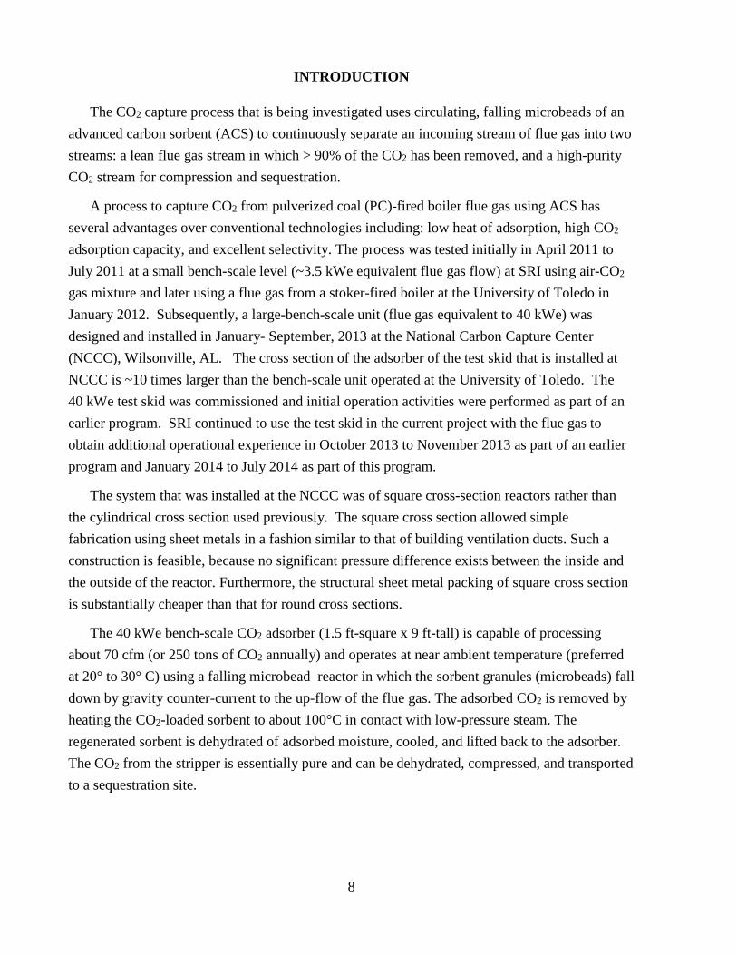
The CO2 capture process that is being investigated uses circulating, falling microbeads of an advanced carbon sorbent (ACS) to continuously separate an incoming stream of flue gas into two streams: a lean flue gas stream in which > 90% of the CO2 has been removed, and a high-purity CO2 stream for compression and sequestration.
A process to capture CO2 from pulverized coal (PC)-fired boiler flue gas using ACS has several advantages over conventional technologies including: low heat of adsorption, high CO2 adsorption capacity, and excellent selectivity. The process was tested initially in April 2011 to July 2011 at a small bench-scale level (~3.5 kWe equivalent flue gas flow) at SRI using air-CO2 gas mixture and later using a flue gas from a stoker-fired boiler at the University of Toledo in January 2012. Subsequently, a large-bench-scale unit (flue gas equivalent to 40 kWe) was designed and installed in January- September, 2013 at the National Carbon Capture Center (NCCC), Wilsonville, AL. The cross section of the adsorber of the test skid that is installed at NCCC is ~10 times larger than the bench-scale unit operated at the University of Toledo. The 40 kWe test skid was commissioned and initial operation activities were performed as part of an earlier program. SRI continued to use the test skid in the current project with the flue gas to obtain additional operational experience in October 2013 to November 2013 as part of an earlier program and January 2014 to July 2014 as part of this program.
The system that was installed at the NCCC was of square cross-section reactors rather than the cylindrical cross section used previously. The square cross section allowed simple fabrication using sheet metals in a fashion similar to that of building ventilation ducts. Such a construction is feasible, because no significant pressure difference exists between the inside and the outside of the reactor. Furthermore, the structural sheet metal packing of square cross section is substantially cheaper than that for round cross sections.
The 40 kWe bench-scale CO2 adsorber (1.5 ft-square x 9 ft-tall) is capable of processing about 70 cfm (or 250 tons of CO2 annually) and operates at near ambient temperature (preferred at 20° to 30° C) using a falling microbead reactor in which the sorbent granules (microbeads) fall down by gravity counter-current to the up-flow of the flue gas. The adsorbed CO2 is removed by heating the CO2-loaded sorbent to about 100°C in contact with low-pressure steam. The regenerated sorbent is dehydrated of adsorbed moisture, cooled, and lifted back to the adsorber. The CO2 from the stripper is essentially pure and can be dehydrated, compressed, and transported to a sequestration site.

9
DESCRIPTION OF THE BENCH-SCALE UNIT
As shown in Figure 1, the 40 kWe bench-scale unit consisted of the following sections from top to bottom: adsorber, transition, stripper, dehydrator, cooler, and sorbent lift. The sorbent microbeads move by gravity from the top of the adsorber to the bottom of the cooler from which they are lifted back to the top. The adsorber, transition, and the stripper sections of the system were filled with structural packing to allow uniform distribution of the sorbent within the sections. The design conditions of the bench-scale unit are listed in Table 1, while Figure 2 is a schematic piping and instrumentation diagram, as designed.
.
Table 1. Design Parameters and Their Values Used in the Field Test at NCCC
Parameter Unit Nominal Value Adsorber column size (square) Meters 0.46 Adsorber column size height Meters 3 Stripper column size (square)
Meters 0.30
Stripper column height Meters 2.5 Total height of the system Meters 15 Flue gas flow rate Liters/min (STP) 1000 to 2000 CO2 level in the flue gas % 4.5 to 12 SO2 level in the flue gas ppm <10 CO2 product flow liters/min (STP) 100 to 200 Pressure drop in the adsorber Pa (inch water) 125 to 250 (0.5 to 1.0) Sorbent flow rate kg/min 12 Adsorber temperature Degrees Kelvin (Celsius) 293 to 303 (20 to 30) Stripper temperature Degrees Kelvin (Celsius) 373 to 393 (100 to 120) Dehydrator temperature Degrees Kelvin (Celsius) 313 to 393 (40 to 120) Cold Sorbent temperature Degrees Kelvin (Celsius) 298 to 303 (25 to 30)
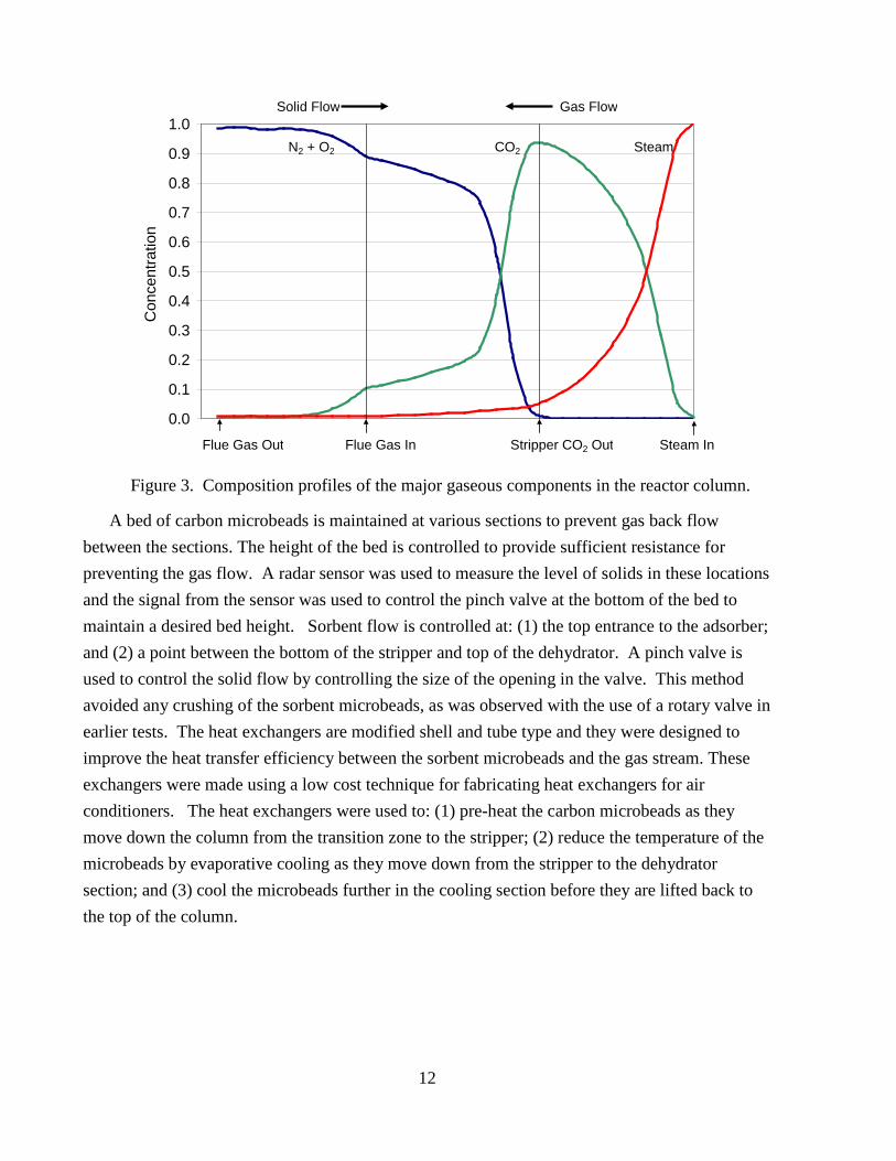
The composition profile of the major gas components in the column is illustrated schematically in Figure 3. The flue gas enters the base of the adsorber section and proceeds upward, where the CO2 is adsorbed by a counter-flow of regenerated CO2-lean sorbent. The CO2-loaded sorbent continues down the column, where it encounters an increasing concentration of CO2 from the CO2 stripper unit. This causes the residual, adsorbed components of air to be swept up the column to exit with the lean flue gas. The sorbent continues down into the CO2
stripper where steam input causes the sorbent temperature to increase, releasing the adsorbed CO2. Note that the steam is used mainly to heat the sorbent microbeads and not necessarily as a carrier gas. The sorbent then proceeds through a dehydrator, where the sorbent is cooled by

10
evaporation of adsorbed steam by a counter flow of air, and finally by a supplemental cooler to bring the sorbent back down to ambient temperature. The steam-air mixture can be sent to the top of the stripper, where the thermal energy in the steam can be used to preheat the sorbent. The cold sorbent microbeads are lifted to the top of the adsorber by pneumatic transport.
Figure 1. A photograph of the skid installed at the NCCC site.
CO2 Lean Flue gas to Stack
CO2 to Stack
SorbentRecirculation
CO2 Adsorber
CO2 Desorber
Dehydrator
Cooler
Flue Gas from FGD
AirAir
Steam
Cooling Water

11
Figure 2. Piping and instrumentation diagram of the system installed at NCCC site.
12
Figure 3. Composition profiles of the major gaseous components in the reactor column.
A bed of carbon microbeads is maintained at various sections to prevent gas back flow between the sections. The height of the bed is controlled to provide sufficient resistance for preventing the gas flow. A radar sensor was used to measure the level of solids in these locations and the signal from the sensor was used to control the pinch valve at the bottom of the bed to maintain a desired bed height. Sorbent flow is controlled at: (1) the top entrance to the adsorber; and (2) a point between the bottom of the stripper and top of the dehydrator. A pinch valve is used to control the solid flow by controlling the size of the opening in the valve. This method avoided any crushing of the sorbent microbeads, as was observed with the use of a rotary valve in earlier tests. The heat exchangers are modified shell and tube type and they were designed to improve the heat transfer efficiency between the sorbent microbeads and the gas stream. These exchangers were made using a low cost technique for fabricating heat exchangers for air conditioners. The heat exchangers were used to: (1) pre-heat the carbon microbeads as they move down the column from the transition zone to the stripper; (2) reduce the temperature of the microbeads by evaporative cooling as they move down from the stripper to the dehydrator section; and (3) cool the microbeads further in the cooling section before they are lifted back to the top of the column.
0.0
0.1
0.2
0.3
0.4
0.5
0.6
0.7
0.8
0.9
1.0
Con
cent
ratio
n
Flue Gas InFlue Gas Out Stripper CO2 Out Steam In
N2 + O2 CO2 Steam
Solid Flow Gas Flow

13
RESULTS AND DISCUSSION
GAS AND SOLID FLOWS
The flue gas flow to the bench-scale unit was provided by NCCC through a 0.1 m (4-inch) diameter pipe at a nominal positive pressure of 12.5 kPa (50 in WC) (with respect to the ambient pressure). The flow was controlled initially by a damper valve and measured by a vortex type flow meter. The gas streams from the bench-scale unit were vented through the return line at NCCC and the return line was at a negative pressure of 3.1 kPa (25 in WC) (with respect to the ambient pressure). The pressure in the flue gas supply line and the vacuum in the return line were larger than expected and prevented the gas flow and column pressure control system from operating as designed. The control dampers did not restrict the flow enough, even when fully-closed, to control the flue gas flow. This was resolved by throttling the flue gas flow using a manual valve. Under these conditions, the flue gas flow was controlled in the design flow range (Figure 4).
Figure 4. Flow control test demonstrating control of flue gas flow between 1500 and 2000 LPM.

14
The flow of solids through the reactor was not measured directly. Instead, a screw feeder controlled the flow rate of microbeads to the pneumatic lift. The feeder was calibrated to provide the flow rate as a function of the rotational rate of the feed screw. Screw feeder rotation was controlled by a speed controller of the motor driving the screw. As observed in the previous bench scale tests, the adsorption and desorption of CO2 on and from the sorbent microbeads are fast. Hence, the concentration of CO2 in the gas can be used to infer the flow of solids through the reactor.
Uniform sorbent flow is required for stable CO2 adsorption. Therefore, the concentration of CO2 in the flue gas exhaust stream (lean out) provides a diagnostic for the uniformity of the solid flow. Two conditions were identified that prevent uniform flow of the sorbent through the adsorber: column back-pressure and condensation of moisture in the column.
The solid flow is controlled through pinch valves: (1) at the top of the adsorber and (2) at the bottom of the stripper. In both cases, a dense bed of sorbent microbeads is used to prevent flow of process gas across the valve. If the process gas pressure below the valve is too large, the gas will push the column of solids up through the pinch valve, momentarily stopping the flow of solids. This condition results in an oscillating flow of sorbent into the adsorber or the dehydrator. The oscillation is observable as an oscillating concentration of CO2 in the flue gas exhaust stream, as shown in Figure 5.
Figure 5. Oscillation of Lean gas concentration as a result of column pressure preventing
uniform solid flow.

15
The back-pressure that caused the flow oscillations was traced to back-pressure in the screen filters that were initially used to disengage the exit gas streams from the solids. These screen filters were replaced by impact separators, which allowed the solids to disengage from the gas stream and return to the main column without creating large back-pressure in the column. After changing the disengagement design, the back-pressure was typically about 1 in WC.
Initially, condensation of moisture as liquid in the stripper resulted in the formation of wet sorbent plugs that prevent smooth sorbent flow. This condition was observed during operation with direct steam injection (Figure 6). The process is designed to prevent condensation of free water in the column through adsorption of the direct steam within the pores of the sorbent. If the adsorbed moisture in the sorbent is not removed effectively in the dehydrator, then the sorbent accumulates moisture until the sorbent does not have enough capacity to adsorb the injected steam. This condition was resolved by increasing the dehydrator air flow to remove more moisture from the sorbent and by reducing the amount of injected steam. A steady sorbent flow was achieved after resolving the back-pressure and steam condensation issues, as shown in Figure 7.
Figure 6: Oscillation of lean gas concentration as a result of condensation in the stripper.

16
Figure 7. Stable adsorption of CO2 concentrations demonstrating uniform sorbent flow.
REACTOR TEMPERATURE PROFILES
Table 2 summarizes the design and observed operating temperatures for various sections of the bench unit, while Figure 8 shows the observed temperatures during testing at the NCCC.
Table 2. Design and Observed Temperatures During a Test at NCCC
Parameter Design Value Observed Value Adsorber temperature (°C) 20 to 30 50 to 60 Stripper temperature (°C) 100 to 120 120 Dehydrator top temperature (°C) 120 130 Cold Sorbent temperature (°C) 25 to 35 45 to 50
The temperature of the adsorber top was approximately 50°C or close to the temperature at the base of the sorbent cooler, indicating that the sorbent did not cool significantly during its pneumatic transport to the top of the adsorber. During previous bench-scale tests, the sorbent microbeads were cooled to the design conditions. It is believed that the higher than expected temperature of the sorbent leaving the sorbent cooler is due to the relatively large gap between the tubes in the heat exchanger. The low cost fabrication method did not allow the use of small diameter tubes and tight spacing. The larger spacing between the tubes allowed reduced heat transfer between the tubes and the sorbent microbeads.

17
Figure 8. The observed temperatures at the various sections of the reactor.
The temperature at the bottom of the adsorber increased to 55 to 60°C during NCCC testing, which is mainly due to the adsorption of gases, particularly CO2 on the sorbent. The temperature at the top of the stripper was at 120°C, close to its design value. The temperature at the top of the dehydrator (130°C) was slightly higher than the design value, mainly due to the fact that steam was supplied to the tubes in the dehydrator at 40 psig. The pressure of the steam was set to that value because the steam pipe supplied steam to several other locations (see below). The dehydrator can operate effectively at the design temperature.
STEAM DEMAND MEASUREMENTS
A series of experiments in August 2014 was conducted to determine the total steam consumption of the bench unit under a variety of operating conditions. For these tests, a vortex-style steam flow meter was installed on the steam feed line downstream of the pressure reduction valve. The steam meter was factory supplied to read out pounds per hour of steam for 40 psig steam. This steam line supplies steam for the heat recovery unit (simulating sorbent preheating from the dehydrator exhaust), the dehydration unit, and the steam-to-steam heat exchanger for

18
direct steam injection. The steam demand was measured under four different conditions to characterize the various heat loads in the system.
1. Baseline heat loss was determined by measuring steam demand with all other flows (i.e., flue gas, sorbent and dehydrator-air) off. This measurement was performed overnight three times.
2. Heat transfer to the circulating sorbent was measured by varying the sorbent recirculation rate with no flue gas flow.
3. Heat load for the direct steam generator was measured by determining the change in steam demand as the water flow to the steam generator was increased.
4. Total steam demand was measured during full operation of the system.
The baseline steam demand as a function of time for three overnight measurements is shown in Figure 9. This baseline steam demand represents parasitic heat losses from the column and inefficiency in the thermostatic steam traps, releasing steam into the condensate line. The average baseline steam demand is 12-times the projected energy (50 kJ/mole of CO2) demand for the process. This is a result of the small-scale of the current system with limited insulation and large surface area-to-volume ratio. As the process is scaled-up, the total steam demand will approach the adiabatic value.
Figure 9. Baseline steam demand. Note: The various colors represent consecutive days of operation.

19
Dry Sorbent Circulation
The steam demand was monitored at three different sorbent recirculation rates. The temperature of the column was measured above and below the heat exchanger situated between the transition and stripper sections. In the pilot-scale system, this heat exchanger will be used to recover the heat value of the dehydrator exhaust. In this bench system, this heat recovery was simulated by feeding steam to this heat exchanger. The heat exchanger has a novel design to accommodate three distinct flows: the counter-current flows of the sorbent and process gas on the shell-side, and the flow of the hot dehydrator exhaust on the tube-side to provide heating. The dry sorbent recirculation test allowed the characterization of heat transfer from the steam on the tube-side to the sorbent on the shell-side, without the complicating counter-flow of the process gas. This represents the lower limit on heat transfer since the process gas flow will increase the heat transfer rate. By varying the sorbent flow, the effect of changing sorbent density in the heat exchanger effectiveness was characterized. Figure 10 shows the steam demand and the temperature above and below the heat exchanger at four different sorbent flow rates: 0, 6, 12, and 18 kg/min. During the initial 120 min, no sorbent was circulated.
Figure 10. Steam demand and sorbent temperature at various sorbent flow rates.
From the above data, the effective heat transfer coefficient of the heat exchanger was calculated by two methods. First, the temperature difference between the steam (at 140°C) and the sorbent above and below the heat exchanger was determined. From the heat capacity and sorbent flow rate, the surface area of the heat exchanger tubes, and the temperature differences; an effective heat transfer coefficient was calculated for the heat exchanger. For the second

20
method, the increased steam demand was used to calculate the heat transferred to the sorbent. The results are shown in Figure 11. The difference in estimated heat transfer is a result of inefficiency in heat transfer between the steam and the sorbent. The heat delivered to the sorbent is approximately 50% of the heat supplied by the increase of steam flow. The remaining energy represents thermal losses due to the small-scale of this system.
Figure 11. Effective heat transfer coefficient as a function of sorbent flow rate.
The heat transfer rate is found to increase significantly as the sorbent flow rate is increased. This is a result of the increased sorbent density in the heat exchanger, providing more contact between sorbent and heat exchange tubes. This means that it is possible to improve heat exchanger performance while also reducing cost by decreasing the heat exchanger diameter. Modeling of the gas flow rate at this location in the column shows that the heat exchanger cross-sectional area could be reduced by a relative factor of five, resulting in a significant capital cost savings.
Steam Generator for Direct Steam Injection
The direct steam injector used in this system was designed to provide direct steam at a well-controlled rate. Reliable steam flow meters are not available at very small sizes so it is not possible to simply regulate the steam flow from the house steam line using a control signal from a steam meter. Instead, steam was produced by vaporizing a regulated flow of water using a steam-to-steam heat exchanger. The energy to vaporize the direct steam was provided by the house steam. The increase in steam demand can be observed as the water flow to the steam generator is increased (Figure 12).

21
Figure 12. Increase in total steam demand due to direct steam generation.
From these data, the efficiency of the steam generator was estimated by taking the ratio of the direct steam flow rate and the increase in total steam flow. The results are shown in Table 3 below.
Table 3. Efficiency of Steam Generation for Use in the Stripper
Water Injection Rate (g/min) Steam Generated
kg/hr (lb/hr) Increase in steam load
kg/h (lb/hr) Efficiency
100 5.9 (13) 10.5 (23) 57% 150 9.1 (20) 18.6 (41) 49% 200 11.8 (26) 26.8 (59) 45%

22
CO2 CAPTURE FROM THE FLUE GAS
A CO2 capture efficiency of approximately 68% was achieved as calculated from the composition of adsorber inlet and outlet gas streams (Figure 13). The decreased capture efficiency, compared to previous bench scale tests, was due to two factors: increased temperature of the sorbent in the adsorber and reduced height of the adsorber. The temperature of the sorbent microbeads at the adsorber top (Figure 14) was higher than the design value due to insufficient cooling at the sorbent cooler section at the bottom of the column. Comparing Figures 13 and 14, it is apparent that the CO2 capture efficiency correlates strongly with adsorber temperature. As the adsorber temperature decreases, the capture efficiency increases. In addition, the reduced efficiency observed in these tests is due to a short residence time of the gas in the adsorber. The short residence time was due to an adsorber height reduction of 10% to allow a taller disengagement section for separating the sorbent microbeads from the pneumatic feed air.
Figure 13. The capture efficiency of CO2 in the adsorber.

23
Figure 14. Changes in the temperature at the adsorber top and bottom positions.
The small changes in CO2 concentration described in Figure 13 are due to pressure fluctuations in the flue gas feed line and discharge line at NCCC. The adsorber, transition, and stripper sections in the bench-scale unit have very low pressure drop (~1-inch WC measured across adsorber and <1 inch WC in transition and stripper section) and hence, they are susceptible to such fluctuations. The large pressure difference between the positive pressure flue gas supply and negative pressure return line caused difficulties in the control of gas and sorbent flows in the reactor column and required constant manual attention. Successful, unattended operation would require a more sophisticated control valve arrangement than the simple damper controls used in the current skid and they will be implemented in a future, pilot-scale unit.
Figure 15 illustrates the temperatures in other sections of the reactor column during this test. Figure 16 illustrates the characteristics of the stripper exhaust stream. The purity of the CO2 gas was about 93% and the CO2 flow was approximately 95 liters/min. The variation in CO2 flow is due to manual adjustment of the stripper exhaust value. The CO2 flow agrees reasonably with the quantity of CO2 captured in the adsorber (~100 liters/min), indicating that very little CO2 exits with the sorbent at the bottom of the stripper.

24
Figure 15. The observed temperatures at various sections of the bench unit.
Figure 16. The observed CO2 purity and flow in the stripper exhaust.

25
The total steam demand was monitored during a daytime run of full system operation (Figure 17). Also shown are the CO2 concentrations of the flue gas supply, the flue gas exit and the stripper exit. The increased steam demand of 45 kg/h (100 lb/hr) from the overnight baseline is approximately four-times the expected demand for an adiabatic system of this size. This factor can be understood as due to two effects. First, the current bench system is not recovering the heat value from the dehydrator exhaust, but the effect of that heat recovery was simulated using steam in the heat recovery heat exchanger. The result is that the net steam demand is doubled compared to a system where the dehydrator exhaust is used to preheat the sorbent in the stripper. Second, the efficiency of heat delivery from the steam supply to the system was found to be only about 50% (Table 3), resulting in another factor of two increase in steam compared to an adiabatic system.
The steam demand measurements can be interpreted as follows: the steam used in the bench-scale unit during flue gas flow is approximately 127 kg/h (280 lb/h), comprised of 72 kg/h (160 lb/h) for baseline demand, 36 kg/h (80 lb/h) for sorbent preheating, and 18 kg/h (40 lb/h) for generation of steam for injection into the stripper. The sensible heat in the sorbent microbeads is not recovered in this bench-scale operation.
Figure 17. Steam demand and performance during full operation.
For estimation purposes, it is assumed that 40 lb/h is the steam demand for recovering CO2 in the stripper. This steam consumption is higher than the value for adiabatic operation, because heat losses in the stripper were not measured during standby mode. Note that the heat losses during flue gas operation can be more than the baseline demand as the stripper is at a higher

26
temperature (100 to 120°C) than during the overnight standby conditions. This assumption is valid, because the preheater is situated above the stripper section and it cannot heat the stripper section.
The stripper CO2 flow rate is 11 kg/h (24 lb/h) and the observed steam demand is approximately 1.7 kg of steam/kg CO2. This value is within a factor of two for conditions in which no recovery of the sorbent sensible heat is practiced. Note that the steam demand is dominated by the sensible heat of the sorbent. If the CO2 capture efficiency approached the design goal of 90%, more CO2 would have been captured and the steam demand per unit of CO2 captured would have been reduced correspondingly.

27
CONCLUSIONS
The main objective of the 40 kWe bench-scale test at the NCCC was to field test the carbon sorbent microbead process using a slipstream of coal-derived flue gas from a PC-fired boiler. Previous tests used either an air-CO2 gas mixture or flue gas from a stoker-fired boiler. The tests were to determine the efficiency of CO2 capture and the purity of the CO2 product gas under steady-state conditions. The information obtained in the field test will be used to design a pilot plant system in the future.
The bench-scale unit was operated for a cumulative duration of ~250 h. Several issues were identified during the operation and successful remedies were implemented. Also, the flue gas availability was sporadic at the NCCC site. The following conclusions can be derived from the operational results:
• Although the CO2 capture efficiency was ~67%, the cause of the decreased efficiency is due to high adsorber temperature and decreased gas residence time in the adsorber. The adsorber temperature was influenced mainly by the extent of sorbent cooling in the sorbent cooler and secondarily the ambient temperature. If the adsorber temperature and residence time parameters were controlled to approach the design values, then the CO2 capture efficiency would have reached the design value. Increased heat transfer rate at the sorbent cooler and a taller adsorber section will satisfy these requirements with minimal changes.
• The CO2 purity at the stripper exit gas was approximately 93%, slightly lower than what was achieved earlier in small bench-scale tests. This reduced purity is due to the changes in the relative dimensions of the transition section. To approach 100% CO2 purity, the transition section will be redesigned with a taller height and narrower cross-section than was designed.
• The large pressure difference between the positive pressure flue gas supply and negative pressure return line caused difficulties in the control of gas and sorbent flows in the reactor column and required constant manual attention. Successful, unattended operation would require a more sophisticated control valve arrangement than the simple damper controls used in the current skid and such controls will be implemented in the pilot unit design.
• Steam use measurements indicated that the steam demand was larger than anticipated due to severe heat losses. However, analysis of the data indicates that the heat
28
requirements can be close to the original assumed value of 50 kJ/mole of CO2 when a more adiabatic system is used.
• Sorbent breakage that was observed in the test was mainly due to high velocity impact collisions in the pneumatic transport and disengagement sections.
• The issues encountered in the skid operation were mostly mechanical in nature as they are not uncommon during scale-up. A more conservative design could have been adapted, but the design parameters were pushed to expose the limits. The experience provided the critical knowledge for the pilot plant design so as not to over-design with the concomitant increase in the construction cost. If the pilot unit would have been designed based on earlier, small bench scale test data (a scale up factor of 250), it will be either over designed or cost of corrective action could be excessively high.
a. The pneumatic lift of the sorbent microbeads is not the preferred design for the pilot scale unit. A bucket elevator will be used to lift the sorbent microbeads. The operation of the skid provided valuable information for the design of the pilot scale unit, if the pneumatic lift is to be used.
b. The operation also showed that pinch valves can be used successfully to control the flow of the sorbent microbeads within the integrated column.
c. Preliminary design information was obtained on the effectiveness of the heat exchangers. The density of the tubes within the heat exchanger needs to be increased.
d. Direct steam injection must be used to a minimum level by preheating the sorbent microbeads.
e. Structured packing gas-solid disengagement effectively separates the sorbent microbeads with very low pressure drop. These separators can be operated hot and do not become plugged by accumulation of fines, but require multiple layers of packing for complete separation.
f. Corrosion was observed in 304 grade stainless steel in the hot areas (stripper) of the reactor, suggesting that 316 grade stainless steel will be required for such sections.