beibei ren, yeqin wang & qing-chang zhong
TRANSCRIPT

Full Terms & Conditions of access and use can be found athttp://www.tandfonline.com/action/journalInformation?journalCode=tcon20
Download by: [Texas Tech University Libraries] Date: 14 February 2016, At: 12:58
International Journal of Control
ISSN: 0020-7179 (Print) 1366-5820 (Online) Journal homepage: http://www.tandfonline.com/loi/tcon20
UDE-based control of variable-speed wind turbinesystems
Beibei Ren, Yeqin Wang & Qing-Chang Zhong
To cite this article: Beibei Ren, Yeqin Wang & Qing-Chang Zhong (2016): UDE-basedcontrol of variable-speed wind turbine systems, International Journal of Control, DOI:10.1080/00207179.2015.1126678
To link to this article: http://dx.doi.org/10.1080/00207179.2015.1126678
Accepted author version posted online: 03Dec 2015.Published online: 04 Jan 2016.
Submit your article to this journal
Article views: 51
View related articles
View Crossmark data

INTERNATIONAL JOURNAL OF CONTROL, http://dx.doi.org/./..
UDE-based control of variable-speed wind turbine systems
Beibei Rena, Yeqin Wangb and Qing-Chang Zhongc
aDepartment of Mechanical Engineering, Texas Tech University, Lubbock, TX, USA; bNational Wind Institute, Texas Tech University, Lubbock, TX,USA; cDepartment of Electrical and Computer Engineering, Illinois Institute of Technology, Chicago, IL, USA
ARTICLE HISTORYReceived February Accepted November
KEYWORDSWind turbine; UDE; vectorcontrol; current decouplingcontrol; DC-link voltageregulation; modeluncertainty; back-to-backconverters
ABSTRACTIn this paper, the control of a PMSG (permanent magnet synchronous generator)-based variable-speed wind turbine system with a back-to-back converter is considered. The uncertainty and dis-turbance estimator (UDE)-based control approach is applied to the regulation of the DC-link voltageand the control of the RSC (rotor-side converter) and the GSC (grid-side converter). For the rotor-sidecontroller, the UDE-based vector control is developed for the RSC with PMSG control to facilitate theapplication of the MPPT (maximum power point tracking) algorithm for the maximum wind energycapture. For the grid-side controller, the UDE-based vector control is developed to control the GSCwith the power reference generated by a UDE-based DC-link voltage controller. Compared with theconventional vector control, the UDE-based vector control can achieve reliable current decouplingcontrol with fast response. Moreover, the UDE-based DC-link voltage regulation can achieve stableDC-link voltage undermodel uncertainties and external disturbances, e.g. wind speed variations. Theeffectiveness of the proposed UDE-based control approach is demonstrated through extensive sim-ulation studies in the presence of coupled dynamics, model uncertainties and external disturbancesunder varying wind speeds. The UDE-based control is able to generate more energy, e.g. by 5% forthe wind profile tested.
1. Introduction
Wind energy has been regarded as an environmentallyfriendly alternative energy source and has attracted mostof attention (Zhong&Hornik, 2012). In contrast to fixed-speed wind turbines, variable-speed wind turbines aredesigned to follow wind speed variations in low windsto maximise aerodynamic efficiency, so they have thepotential to produce more energy than fixed-speed ones(Ozbay, Zergeroglu, & Sivrioglu, 2008; Palejiya, Shaltout,Yan, & Chen, 2015). PMSG (permanent magnet syn-chronous generator) is one of the popular power genera-tors in variable-speedwind turbine systems, as PMSGhasexcellent advantages, such as the elimination of DC exci-tation, high power density, high efficiency, and high reli-ability (Li, Haskew, Swatloski, & Gathings, 2012; Shariat-panah, Fadaeinedjad,&Rashidinejad, 2013; Zhang, Zhao,Qiao, & Qu, 2014).
In PMSG-based variable-speed wind turbine systems,full-scale back-to-back converters are often adopted forachieving maximum capture of wind power, provid-ing low harmonic distortion of current, and operat-ing the wind farm for provision of ancillary services(Seixas, Melicio, & Mendes, 2014; Zhong, Ma, Ming, &Konstantopoulos, 2015). The full-scale back-to-back
CONTACT Qing-Chang Zhong [email protected]
converters include a RSC (rotor-side converter) con-nected with the generator, a GSC (grid-side converter)connected to the grid, and a DC-link capacitor placedbetween the RSC and the GSC. The vector control, a con-ventional and classical control strategy based on the d–q reference frame, is still applied in both the RSC forPMSG control and the GSC for power output control(Li et al., 2012; Shariatpanah et al., 2013; Yuan, Wang,Boroyevich, Li, & Burgos, 2009). However, the conven-tional vector control faces some difficulties, for example,it is sensitive to parameters tuning and uncertainty inthe d–q reference frame for current decoupling control(Zhong et al., 2015), the parameters tuning and uncer-tainty also reduce system stability and reliability (Li et al.,2012), the system response with current control is lim-ited by time constant of the armature winding (Zhong,Rahman, Hu, & Lim, 1997), and the coupled currentdynamics in d–q reference frame enhance the difficultyof current regulation (Mohamed & Lee, 2006; Sneyers,Novotny, & Lipo, 1985). In recent years, the conventionalvector control was improved by feed-forward compen-sation (Mohamed & Lee, 2006; Morimoto, Sanada, &Takeda, 1994) for current decoupling control, and hys-teresis band PWM strategy (Rebeiro & Uddin, 2012)for nonlinear effect. The direct-current vector control
© Taylor & Francis
Dow
nloa
ded
by [
Tex
as T
ech
Uni
vers
ity L
ibra
ries
] at
12:
58 1
4 Fe
brua
ry 2
016

2 B. REN ET AL.
(Li et al., 2012) was proposed to enhance system stability,reliability and efficiency for PMSG-based wind turbines.The direct torque control was compared with conven-tional vector control for PMSM (permanent magnet syn-chronous motor) control to achieve fast system response(Zhong et al., 1997), and was also adopted in PMSG-based wind turbines (Haque, Saw, & Chowdhury, 2014;Zhang et al., 2014). The synchronverter technology wasproposed for PMSG-based wind turbines system both onthe RSC and the GSC in Zhong et al. (2015) to make thesystem more friendly to the grid, as synchronverter tech-nology is independent to system parameters.
Although the back-to-back converters with vectorcontrol are widely used because it simplifies the controldesign, it has potential difficulties to achieve maximumwind power capture and DC-link voltage regulation forthe whole wind turbine system, as the disturbance anduncertainties are difficult to handle (Chen, Yang, Guo, &Li, 2015; Li, Yang, Chen, & Chen, 2014). The wind tur-bines are large with flexible structures operating in noisyenvironments, and aerodynamic loads on the turbinesare highly nonlinear (Johnson, Fingersh, Balas, & Pao,2004; Leith & Leithead, 1997). The wind speed measure-ment on the nacelle is not suitable for feed forward con-trol, and precise estimation of wind speed is very difficult(Soltani et al., 2013). The DC-link voltage is influencedbymany factors, such as fluctuating power captured fromwind, non-sinusoidal currents and reactive power deliv-ered to the grid, and equivalent series resistance andinductance in the DC-link capacitor (Shariatpanah et al.,2013). In order to achieve themaximumwind power cap-ture, someMPPT (maximumpower point tracking) algo-rithms have been studied with fuzzy-logic-based control(Chedid, Karaki, & El-Chamali, 2000; Simoes, Bose, &Spiegel, 1997), wind speed estimation-based algorithm(Bhowmik, Spee, & Enslin, 1999) and optimal torquecontrol (Morimoto, Nakayama, Sanada, & Takeda, 2005).Adaptive control scheme was proposed in Johnson et al.(2004) and Johnson, Pao, Balas, and Fingersh (2006) todeal with complex aerodynamics for MPPT. The conven-tional PI (proportional-integral) controller is still widelyadopted in Shariatpanah et al. (2013), Li et al. (2012) andZhong et al. (2015) forDC-link voltage regulation inwindturbine systems.
In this paper, a PMSG-based variable-speed wind tur-bine system with back-to-back converters is studied withthe goals of maximum wind power capture and PMSGcontrol in the rotor-side controller, and DC-link volt-age regulation and power output control in the grid-side controller. To achieve these goals, the model of aPMSG-based variable-speed wind turbine with back-to-back converters is established at first, then the UDE(uncertainty and disturbance estimator)-based control
approach is applied for the RSC, the GSC and DC-link voltage regulation, respectively. The UDE algo-rithm, which was proposed in Zhong and Rees (2004), isbased on the assumption that the uncertainty and distur-bance can be estimated by using a filter with the appro-priate bandwidth. In recent years, the UDE algorithmdemonstrated excellent performance in handling uncer-tainties and disturbances in different systems, and wasemployed to robustify an input–output linearisation con-troller (Talole & Phadke, 2009; Talole, Chandar, & Kolhe,2011) and input–output delay systems (Sun, Zhang, Li,Lee, & Zhang, 2015), and applied to robust trajectorytracking (Kolhe, Shaheed, Chandar, & Taloe, 2013), aclass of non-affine nonlinear systems (Ren, Zhong, &Chen, 2015), three-DOF experimental helicopters (Zhu,Liu, & Li, 2015), piezoelectric actuator (Chen, Ren, &Zhong, 2015), and quadrotor vehicles (Sanz, Garcia,Zhong, & Albertos, 2015). In this paper, in the rotor-sidecontroller, the optimal torque MPPT is first adopted formaximumwind energy capture, then theUDE-based vec-tor control is developed for RSC with PMSG control tofacilitate the application of the MPPT. In the grid-sidecontroller, the UDE-based DC-link voltage regulationcontrol is proposed to generate a power output reference,then the UDE-based vector control is developed for theGSC with power output control to facilitate the achieve-ment of reliable DC-link voltage regulation. Comparedwith the convectional vector control, the UDE-based vec-tor control can achieve the reliable current decouplingcontrol in the d–q reference frame with fast response invarying wind speed conditions. And compared with theconvectional PI controller, the UDE-based DC-link volt-age regulation control can achieve the model uncertaintycompensation and external disturbance rejection.
The main contributions of this paper are highlightedas follows:
� TheUDE-based vector control is developed for boththe RSC with PMSG control and the GSC withpower output control to achieve reliable currentdecoupling control with fast response in varyingwind speed conditions.
� Reliable DC-link voltage regulation control is devel-oped based on the UDE algorithm to deal withmodel uncertainty, such as power losses, equivalentseries resistance, equivalent series inductance andthe reactive power on the capacitor, and external dis-turbances with varying wind speed conditions.
The effectiveness of the proposed UDE-based controlapproach is demonstrated through extensive simulationstudies using theMatlab/Simulink/Simpowersystem. Thecomparison with the conventional PI control is also pro-vided to show the robustness and higher energy captureof the proposed approach.
Dow
nloa
ded
by [
Tex
as T
ech
Uni
vers
ity L
ibra
ries
] at
12:
58 1
4 Fe
brua
ry 2
016

INTERNATIONAL JOURNAL OF CONTROL 3
The rest of the paper is organised as follows. Section 2briefly introduces mechanical part, electrical part andcontrol part of a PMSG-based variable-speed wind tur-bine system with back-to-back converters. Section 3details the modelling for this wind turbine system. Therotor-side controller is designed in Section 4 and the grid-side controller in Section 5. Effectiveness of the proposedapproach is demonstrated through simulation studies inSection 6, before the concluding remarks are made inSection 7.
2. System description
Figure 1 shows a PMSG-based wind turbine system,which consists of three parts: mechanical part, electri-cal part and control part. In mechanical part, the rota-tional blades catch wind energy that is then transferredto the generator through a gear box. The gear box con-verts high-torque, low-speed mechanical power on theblade side to low-torque, high-speed mechanical poweron the generator side. The generator, convertingmechan-ical power into AC electrical power, is a standard surface-mounted PMSG with its stator windings connected tothe RSC.
The electrical part is the standard back-to-back con-verters with one side connected to a generator and theother side connected to the grid. The RSC converts vari-able frequency AC power generated by PMSG to DCpower fed into the GSC. The GSC converts the DC powerto fixed frequency electricity that is compatible with theAC grid. And a DC-link capacitor is placed betweenthe RSC and the GSC to smooth the DC-link voltage.Three-phase LC (inductor and capacitor) filters are addedbetween the GSC and the grid to filter the PWM (pulse-width modulation) voltages generated by the GSC.
In this paper, a control structure as shown in Figure 1,including the rotor-side controller and the grid-side con-troller, is employed for the RSC and theGSC, respectively.The DC-link is the key linkage between the RSC and theGSC, and a stable DC-link voltage guarantees the sta-ble operation of both the RSC and the GSC. The goalsof the rotor-side controller are maximum power capturefrom the wind with the MPPT (maximum power pointtracking) control algorithm, and converting AC power toDC power (the same as PMSG control) with the UDE-based vector control. The goals of the grid-side controllerare keeping the DC-link voltage stable with the UDE-based DC-link voltage control, and converting DC powerto grid AC power (the same as power output control)with theUDE-based vector control. For the grid-side con-troller, the UDE-based DC-link voltage regulation con-trol regulates the DC-link voltage at a desired constantlevel through sending almost all the DC power generatedby the RSC to the grid. As a result, a stable DC-link volt-age is achieved.
3. Systemmodelling
3.1 Wind power
The power produced by a wind turbine can be calculatedas (Heier &Waddington, 1998)
Pm = 12ρπR2v3
wCp(λ, β), (1)
where ρ is the air density, R is the radius of the rotor, vw
is the wind speed, Cp(λ, β) is the power coefficient that isdependent on the turbine design, β is the pitch angle, and
Turbine
Wind
PMSG
A
B
CLC Filter
-
+GearBox
RSC Grid
GSC
Rotor side controller
MPPTUDE-based
vector control for RSC
Grid side controller
UDE-based DC link voltage
regulation control
UDE-based vector control
for GSC
,,
Figure . Schematic diagram of a PMSG-based wind turbine with back-to-back converters.
Dow
nloa
ded
by [
Tex
as T
ech
Uni
vers
ity L
ibra
ries
] at
12:
58 1
4 Fe
brua
ry 2
016

4 B. REN ET AL.
Cp
Tip speed ratio λλ
opt
Figure . Power coefficient Cp as a function of the tip-speed ratioλ (Zhong & Hornik, ).
the tip-speed ratio λ is defined as
λ = ωrR/vw, (2)
where ωr is the rotor speed of the wind turbine.The power coefficient Cp is a highly nonlinear func-
tion of λ and β , which can be approximated as (Heier &Waddington, 1998)
Cp = c1(c2λi
− c3β − c4)e−
c5λi , (3)
with
1λi
= 1λ + c6
− c7β3 + 1
,
where c1–c7 are constant coefficients. For wind turbineswith a fixed pitch angle β , the relationship between Cpand the tip speed ration λ often has the shape shown inFigure 2.
3.2 Dynamicmodel of a PMSG-basedwind turbinewith back-to-back converters
Figure 1 shows the schematic diagram of a PMSG-basedwind turbine with back-to-back converters where theRSC is connected with the generator and the GSC is con-nectedwith the grid. ADC-link capacitor is used betweenthe RSC and the GSC to smooth the DC-link voltage.
.. Model of the PMSG-basedwind turbine with theRSCIn Figure 1, the RSC is used to convert variable frequencyAC power generated by PMSG to DC power fed into theGSC. As shown in Figure 3, the dynamics of the windturbine transmission system (including the gear box, theshafts) between the blades and the generator aremodelledas the spring damper model in Soltani et al. (2013):
Jmωr = Tm − Kθ θ − (Bm + Bθ )ωr + Bθ
γωe, (4)
Jeωe = ηtKθ
γθ + ηtBθ
γωr −
(ηtBθ
γ 2 + Be
)ωe + Te,
(5)
θ = ωr − 1γ
ωe, (6)
where Jm represents the moment of inertia of the bladesand shaft on the low-speed blade side, Bm the viscousdamper of main rotor bearing, and Tm the shaft torquesat the blade end. Stiffness and damping of drive trainare combined into one spring and one damper on bladesside with coefficients Kθ and Bθ . Je is the moment ofinertia of the shaft, gear box and rotor of generator onthe high-speed generator side, Be is the friction-relateddamping constants in generator side. Te is the electro-magnetic torque of PMSG. ηt is the efficiency of the drivetrain. ωr is the angular speed of the shaft at the blade end,ωe is the angular speed of the shaft at the PMSG end,and θ e is the corresponding electrical angle. θ is the shaft
Blade side
Generator side
Figure . Mechanical scheme of the wind turbine transmission system.
Dow
nloa
ded
by [
Tex
as T
ech
Uni
vers
ity L
ibra
ries
] at
12:
58 1
4 Fe
brua
ry 2
016

INTERNATIONAL JOURNAL OF CONTROL 5
torsion on the low-speed shaft. γ is the gear ratio of thegearbox.
It is well known that
Tm = Pmωr
, (7)
where Pm denotes the wind power given by (1).The PMSG can be modelled in the a–b–c coordinates,
α–β coordinates, or d–q coordinates, which can be linkedthrough Clarke transformation or Park transformation.The PMSG model in the d–q coordinates are describedas (Fitzgerald, Kingsley, & Umans, 2003)
Usd = Lsdird + Rsird − pωeLsqirq, (8)Usq = Lsqirq + Rsirq + pωeLsdird + pωeψ f , (9)
whereUsd andUsq represent the stator voltages, ird and irqare the stator currents, Rs represents the stator windingresistance, Lsd and Lsq represent the stator winding induc-tance, p is the number of pole pairs, and ψ f is the coremagnetic flux.
The electromagnetic torqueTe of the PMSGcan be cal-culated as
Te = 32p[ψ f irq − (Lsq − Lsd )irdirq
]. (10)
As the PMSG is considered as the surface-mounted mag-net type, Lsd and Lsq are equal. Then, ird = 0 control canbe adopted for the torque control and Te in (10) can bereduced to
Te = 32pψ f irq, (11)
which indicates that the torque outputTe of PMSG can becontrolled through the adjustment of the q-axis currentirq directly.
.. Model of the GSCwith the DC-link and the gridIn Figure 1, the GSC is used to absorb the DC power fromthe RSC and convert it to the AC grid power. A DC-linkcapacitor between the RSC and the GSC is used to bal-ance the DC-link voltage. However, the DC-link capac-itor can only filter high-order fluctuation on the RSCand the GSC sides. In order to keep the DC-link volt-age stable, the power coming out of the DC-link capac-itor should be equal to the power injected into the capac-itor. In order to filter the PWM (pulse-widthmodulation)noise on the grid side, three-phase LC (inductors andcapacitors) filters are also added between theGSC and thegrid.
The full DC-link dynamics are very complex and can-not be used for control directly (Shariatpanah et al., 2013).
ADC-link voltage equation simplified fromShariatpanahet al. (2013) with unknown parameters is shown as
Vdc = PinCVdc
− PoutCVdc
− PlossCVdc
+ �v0, (12)
where Vdc is the DC-link voltage, C is the capacitancevalue of the DC-link capacitor, Pin represents the DCpower from the RSC, Pout represents the real power out-put of the GSC, Ploss denotes the power losses on theDC-link capacitor and the GSC, and �v0 represents theeffects of unknown parameters, such as equivalent seriesresistance, equivalent series inductance and the reactivepower. TheDC-link dynamics (12) show that theDC-linkvoltage Vdc can be controlled through the adjustment ofthe real power output Pout of the GSC. Normally, Pin canbe measured directly, but Ploss and �v0 are difficult to bemeasured directly.
Similar to the PMSGmodelling in the d–q coordinates,the three-phase grid also can bemodelled in the d–q coor-dinates as Shariatpanah et al. (2013)
Ugd = Lgigd + Rgigd − ωgLgigq + ugd, (13)
Ugq = Lgigq + Rgigq + ωgLgigd + ugq, (14)
where Ugd and Ugq represent the output voltages of theGSC, igd and igq are the output currents of the GSC, Rgand Lg represent the line resistance and inductance, ugdand ugq are the grid voltage, ωg is the grid frequency, andthe corresponding phase angle θ g can be calculated by aPLL (phase-locked-loop). Note that the capacitance Cg ofthe filter capacitors in Figure 1 is very small and only usedfor filtering the high-order noise, which can be ignored inthe modelling for simplification.
The instantaneous real power output Pout and reactivepower output Qout generated from the GSC are definedas
Pout = Ugdigd +Ugqigq, (15)
Qout = Ugdigq +Ugqigd. (16)
For the real power Pout output control of the GSC, igq = 0control is often adopted in the vector control. Then, (15)and (16) can be simplified as
Pout = Ugdigd, (17)
Qout = Ugqigd. (18)
Dow
nloa
ded
by [
Tex
as T
ech
Uni
vers
ity L
ibra
ries
] at
12:
58 1
4 Fe
brua
ry 2
016

6 B. REN ET AL.
4. Design of the rotor-side controller
The control scheme of rotor-side controller (shown inFigure 4) is developed to achieve maximum wind powercapture and PMSG control. In the outer loop, the MPPTcontrol algorithm is adopted to generate a torque refer-ence T∗
e . In the inner loop, the UDE-based vector controlis developed to control the currents ird and irq to achievethe PMSG torque control and convert AC power to DCpower simultaneously.
4.1 MPPT control without wind speed information
It is well known that there are four wind speed regionsfor wind turbine control (Wu, Lang, Zargari, & Kouro,2011). In Region I, the wind speed is lower than the cut-in speed and the wind turbine is closed; in Region II,MPPT control is adopted to extract the maximum windpower at different wind speeds through keeping the opti-mal tip-speed ratio λopt; in Region III, the wind speed ishigher than the rated wind speed and the pitch controlis adopted to keep constant power generation; in RegionIV, the wind speed is higher than the cut-off speed andfull pitch control is adopted to protect the wind turbine.In this work, it is assumed that the wind turbine is oper-ated in Region II to extract the maximum power fromthe wind. In the outer loop of the rotor-side controllershown in Figure 4, the optimal torqueMPPT algorithm inMorimoto et al. (2005) is adopted to catch the maximumpower via adjusting the tip-speed ratio λ in (2) withoutthe wind speed information, as the precise estimation ofwind speed is very difficult (Soltani et al., 2013).
As the power coefficient Cp is a nonlinear functionof λ and β , there is an optimal tip-speed ratio λopt toachieve the optimal power coefficientCp−opt for a constantβ . According to (1) and (7), the optimal torqueTm−opt canbe expressed as
Tm−opt = Koptω2r−opt , (19)
where
Kopt = ρπCp−optR5
2λ3opt
. (20)
According to (2), the optimal blade shaft speedωr−opt sat-isfies
ωr−opt = λoptvω
R.
Replacing ωr−opt with the blade shaft speed ωr in (19)and considering (4)–(6) with the steady angular speed ofthe shaft, steady generator speed and steady shaft torsion
ωr = 0, ωe = 0, θ = 0,
the generator torque reference by the PMSG can beexpressed as
T∗e = −ηtKoptω
2e
γ 3 + ηtBmωe
γ 2 + Beωe.
Here, the generator speedωe is usually adopted to replacethe blade shaft speed ωr for the torque MPPT algorithm,as ωe is easy to obtain.
Usually, the mechanical losses of drive train in (5) canbe ignored with ηt = 1 as it is very small. The referencetorque can be reduced to
T∗e = −Koptω
2e
γ 3 + Bmωe
γ 2 + Beωe. (21)
4.2 UDE-based vector control for RSC-PMSG
In Figure 4, the control objective of the inner loop onthe rotor-side controller is to make the torque output ofPMSG to follow the torque reference T∗
e in (21) throughregulating the PMSG currents in the d–q coordinates. Inparticular, the tracking errors eird = i∗rd − ird and eirq =i∗rq − irq are specified to satisfy the following dynamics:
Coordinate transf.
SVPWM signals
generatorRSC
PARK transf.
CLARKE transf.
MPPT(21)
UDE-basedcontrol (33)
UDE-basedcontrol (34)
Figure . The proposed control scheme on the rotor-side controller.
Dow
nloa
ded
by [
Tex
as T
ech
Uni
vers
ity L
ibra
ries
] at
12:
58 1
4 Fe
brua
ry 2
016

INTERNATIONAL JOURNAL OF CONTROL 7
eird = −Kirdeird, (22)
eirq = −Kirqeirq. (23)
It is noted that in the PMSG model (8) and (9), there arecoupled current dynamics in the d–q coordinates, whichenhance the difficulty of current regulation in the vec-tor control. In this work, the coupled current dynamicswill be regarded as the disturbance terms and handled bythe UDE-based current decoupling control. To facilitatethe control design, the PMSG models (8) and (9) can berewritten as
U ∗sd = Lsdird + Rsird + �ird, (24)
U ∗sq = Lsqirq + Rsirq + pωeψ f + �irq, (25)
where �ird = −pωeLsqirq, �irq = pωeLsdird represent thecoupled terms, which are treated as uncertainties. Com-bining Equations (24) and (22) and combining Equations(25) and (23), then
i∗rd + Rs
Lsdird − U ∗
sd
Lsd+ �ird
Lsd= −Kirdeird,
i∗rq + Rs
Lsqirq − U ∗
sq
Lsq+ pωeψ f
Lsq+ �irq
Lsq= −Kirqeirq.
So, the stator voltage referencesU ∗sd andU
∗sq need to satisfy
U ∗sd = Lsdi∗rd + Rsird + LsdKirdeird + �ird, (26)
U ∗sq = Lsqi∗rq + Rsirq + pωeψ f + LsqKirqeirq + �irq. (27)
According to the system dynamics in (24) and (25), theuncertainty terms can be represented as
�ird = U ∗sd − Lsdird − Rsird,
�irq = U ∗sq − Lsqirq − Rsirq − pωeψ f .
Following the procedures provided in Zhong and Rees(2004), it is assumed that girdf(t) and girqf(t) are theimpulse response of strictly proper stable filters Girdf(s)and Girgf(s) with appropriate frequency characteristicsover the spectrum of �ird and �irq, respectively. Then,�ird and �irq can be accurately approximated by
�ird = �ird ∗ girdf = (U ∗sd − Lsdird − Rsird ) ∗ girdf, (28)
�irq = �irq ∗ girqf = (U ∗sq − Lsqirq − Rsirq
− pωeψ f ) ∗ girqf, (29)
where �ird is an estimate of�ird, and �irq is an estimate of�irq. Replacing �ird with �ird , and �irq with �irq, respec-tively, in (26) and (27) results in
U ∗sd = Lsdi∗rd + Rsird + LsdKirdeird
+ (U ∗sd − Lsdird − Rsird ) ∗ girdf,
U ∗sq = Lsdi∗rq + Rsirq + pωeψ f + LsqKirqeirq
+ (U ∗sq − Lsqirq − Rsirq − pωeψ f ) ∗ girqf.
These result in the UDE-based control laws
U ∗sd = Rsird + L−1
{1
1 − Girdf(s)
}∗ (Lsdi∗rd + LsdKirdeird )
− L−1{
sGirdf(s)1 − Girdf(s)
}∗ (Lsdird ), (30)
U ∗sq = Rsirq + pωeψ f + L−1
{1
1 − Girqf(s)
}
∗ (Lsdi∗rq + LsqKirqeirq)
− L−1{
sGirqf(s)1 − Girqf(s)
}∗ (Lsqirq). (31)
The filter design is very important in the UDE algo-rithm, as the filter should cover the spectrum of distur-bances with the unity gain and zero phase shift. Differ-ent choices of filters will result in different forms of UDEcontroller, which depends on system dynamics and per-formance requirements. In this paper, it is sufficient tochoose Girdf(s) and Girqf(s) as the following first-orderlow-pass filters:
Girdf(s) = 11 + τirds
, Girqf(s) = 11 + τirqs
. (32)
Then,
11 − Girdf(s)
= 1 + 1τirds
,1
1 − Girqf(s)= 1 + 1
τirqs,
and
sGirdf(s)1 − Girdf(s)
= 1τird
,sGirqf(s)
1 − Girqf(s)= 1
τirq.
Therefore, the UDE-based control laws (30) and (31) arecalculated as
U ∗sd = Rsird + Lsdi∗rd + Lsd
τird(1 + τirdKird )eird
+ LsdKird
τird
∫ t
0eirddt,
U ∗sq = Rsirq + Lsdi∗rq + pωeψ f
+ Lsqτirq
(1 + τirqKirq)eirq + LsqKirq
τirq
∫ t
0eirqdt.
Dow
nloa
ded
by [
Tex
as T
ech
Uni
vers
ity L
ibra
ries
] at
12:
58 1
4 Fe
brua
ry 2
016

8 B. REN ET AL.
From Figure 4, it can be seen that i∗rq is generated fromthe torque reference T∗
e where the relationship betweeni∗rq and T∗
e is shown in (11). Since the surface-mountedmagnet type of PMSG is considered, i∗rd is set to zero, andits derivative is also zero. Then, the UDE-based controllaws are reduced to
U ∗sd = Rsird + Lsd
τird(1 + τirdKird )eird + LsdKird
τird
∫ t
0eirddt,
(33)
U ∗sq = Rsirq + Lsdi∗rq + pωeψ f + Lsq
τirq(1 + τirqKirq)eirq
+ LsqKirq
τirq
∫ t
0eirqdt, (34)
where the currents ird and irq can be obtained from three-phase currents ira and irb through the Clarke transforma-tion and Park transformation as shown in Figure 4. Theoutputs of the aboveUDE-based control laws,U ∗
sd andU∗sq,
are converted to six SVPWM (space-vector pulse widthmodulation) signals to drive power electronics of the RSCthrough a coordinate transformation and a SVPWMgen-eration module. The details about the vector control canbe found in Sul (2011).
5. Design of the grid-side controller
In order to achieve the DC-link voltage regulation andpower output control, the control scheme of grid-sidecontroller is shown in Figure 5. In the outer loop of thegrid-side controller, the DC-link voltage regulation withthe UDE algorithm is designed to generate a real poweroutput reference P∗
out . In the inner loop of the grid-sidecontroller, the UDE-based vector control is developed toregulate the currents igd and igq to achieve real poweroutput control and convert DC power to grid AC powersimultaneously.
5.1 UDE-based DC-link voltage regulation
For the grid-side controller, the control objective of theouter loop in Figure 5 is to generate a real power outputreference P∗
out such that the DC-link voltage Vdc in (12)asymptotically tracks a reference voltageV0, in particular,the tracking error ev =Vo −Vdc asymptotically convergesto zero by following the desired error dynamics
ev = −Kvev , (35)
whereKv is an error feedback gain. Instead of the nominalmodel (12), the following modified model is considered
in the presence of the uncertainties and disturbances:
Vdc = PinCV0
− P∗out
CV0+ �v , (36)
where V0 is a constant reference value for Vdc, and �v
represents the lumped uncertainty and disturbance term�v = Pin
CVdc− Pout
CVdc− Ploss
CVdc+ �v0 − Pin
CV0+ Pout
CV0. In the nor-
mal operation condition, the DC-link voltage Vdc shouldbe close to V0.
Combining Equations (35) and (36), there is
V0 − PinCV0
+ P∗out
CV0− �v = −Kvev .
The real power output reference P∗out needs to satisfy
P∗out = −CV0V0 + Pin +CV0�v −CV0Kvev . (37)
According to the system dynamics in (36),�v can be rep-resented as
�v = Vdc − PinCV0
+ P∗out
CV0.
Assume that gvf(t) is the impulse response of a strictlyproper stable filter Gvf(s) with the appropriate frequencycharacteristics over the spectrum of �v . Following thesimilar procedures in Section 4.2, the UDE-based controllaw can be expressed as
P∗out = Pin +CV0
[L−1
{1
1 − Gv f (s)
}∗ (−Kvev )
+ L−1{
sGv f (s)1 − Gv f (s)
}∗Vdc
]. (38)
If the filter Gvf(s) is chosen as the following first-orderlow-pass filter:
Gv f (s) = 11 + τv s
,
the UDE-based control law (38) is derived as follows:
P∗out = Pin −CV0V0 − CV0
τv
[(Kvτv + 1) ev + Kv
∫ t
0evdt
].
Considering V0 as a constant value, V0 = 0. Then, theUDE-based control law can be reduced to
P∗out = Pin − CV0
τv
[(Kvτv + 1) ev − Kv
∫ t
0evdt
].
(39)
Dow
nloa
ded
by [
Tex
as T
ech
Uni
vers
ity L
ibra
ries
] at
12:
58 1
4 Fe
brua
ry 2
016

INTERNATIONAL JOURNAL OF CONTROL 9
Coordinate transf.
SVPWM signals
generatorGSC
PARK transf.
CLARKE transf.
UDE-basedcontrol (39)
UDE-basedcontrol (46)
UDE-basedcontrol (47)
Phase locked loop
PARK transf.
CLARKE transf.
Figure . The proposed control scheme for the grid-side controller.
5.2 UDE-based vector control for GSCwith realpower output control
In Section 5.1, the UDE-based DC-link voltage regula-tion control is used to generate a real power output ref-erence P∗
out in (39) of the grid-side controller to achievethe DC-link voltage regulation. Similar to the modifiedvector control of PMSG in Section 4.2, in this section,the UDE-based vector control is developed to achieve theGSC real power output control by adjusting the currentigd as shown in Figure 5.
The objective is to make the grid currents track thereference currents in d–q coordinates which are obtainedby the real power output reference P∗
out , and the trackingerrors eigd = i∗gd − igd , eigq = i∗gq − igq asymptotically con-verge to zero with the desired error dynamics specifiedas
eigd = −Kigdeigd, (40)eigq = −Kigqeigq. (41)
Similar to the voltage equations of PMSG, the currentcoupling items in Equations (13) and (14) can be rep-resented as uncertainty terms �igd = −ωgLgigq, �igq =ωgLgigd to facilitate the current decoupling control of igdand igq as
Ugd = Lgigd + Rgigd + ugd + �igd, (42)Ugq = Lgigq + Rgigq + ugq + �igq. (43)
Following the similar procedures of the UDE-based con-trol in Section 4.2, the control laws can be obtainedas
U ∗gd = Rgigd + ugd + L−1
{1
1 − Gigdf(s)
}
∗ (Lgi∗gd + LgKigdeigd )
− L−1{
sGirdf(s)1 − Girdf(s)
}∗ (Lgigd ), (44)
U ∗gq = Rgigq + ugq + L−1
{1
1 − Gigqf(s)
}
∗ (Lsdi∗rq + LgKigqeigq)
− L−1{
sGirqf(s)1 − Girqf(s)
}∗ (Lgigq), (45)
where gigdf(t) and gigqf(t) are the impulse response ofstrictly proper stable filters Gigdf(s) and Gigqf(s) withappropriate frequency characteristics over the spectrumof �igd and �igq, respectively. When both filters Gigdf(s)and Gigqf(s) are designed as the following first-order low-pass filters
Gigdf(s) = 11 + τigds
, Gigqf(s) = 11 + τigqs
,
theUDE-based control laws (44) and (45) can be obtainedas
U ∗gd = Rgigd + ugd + Lgi∗gd + Lg
τigd(1 + τigdKigd )eigd
+ LgKigd
τigd
∫ t
0eigddt,
U ∗gq = Rgigq + ugq + Lgi∗gq + Lg
τigq(1 + τigqKigq)eigq
+ LgKigq
τigq
∫ t
0eigqdt.
Dow
nloa
ded
by [
Tex
as T
ech
Uni
vers
ity L
ibra
ries
] at
12:
58 1
4 Fe
brua
ry 2
016
10 B. REN ET AL.
From Figure 5, it can be seen that i∗gd is generated fromthe real power output reference P∗
out where the relation-ship between i∗gd and P
∗out is shown in (17). i∗gq is set to zero,
and its derivative is also zero. Then, the UDE-based con-trol laws can be reduced to
U ∗gd = Rgigd + ugd + Lgi∗gd + Lg
τigd(1 + τigdKigd )eigd
+ LgKigd
τigd
∫ t
0eigddt, (46)
U ∗gq = Rgigq + ugq + Lg
τigq(1 + τigqKigq)eigq
+ LgKigq
τigq
∫ t
0eigqdt. (47)
It is worth noting that the minimal value ofU ∗gd is the ugq,
which can be measured as shown in Figure 5. So, U ∗gd is
non-zero and can be used as a denominator in Figure 5 togenerate i∗gd . Then,U
∗gd andU
∗gq are adopted to generate the
SVPWM signals to drive power electronics of the GSC.
6. Simulation studies
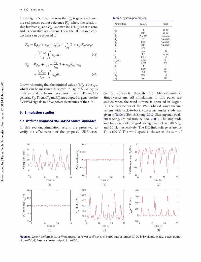
6.1 With the proposed UDE-based control approach
In this section, simulation results are presented toverify the effectiveness of the proposed UDE-based
Table . System parameters.
Parameters Values Unit
Jm kg m
Je . kg m
Kθ
× Nm/radBm Nm/rad/sBθ
. Nm/rad/sBe . Nm/rad/sγ . –R . mρ . kg m
Rs . �
Lsd , Lsq . mHψ f . V sp –C µFLg . mHRg . �
Cg µF
control approach through the Matlab/Simulink/Simpowersystem. All simulations in this paper arestudied when the wind turbine is operated in RegionII. The parameters of the PMSG-based wind turbinesystem with back-to-back converters under study aregiven in Table 1 (Ren & Zhong, 2013; Shariatpanah et al.,2013; Song, Dhinakaran, & Bao, 2000). The amplitudeand frequency of the grid voltage are set as 380 Vrmsand 50 Hz, respectively. The DC-link voltage referenceV0 is 600 V. The wind speed is chosen as the sum of
0 10 20 304
6
8
10
12
14
16
Win
d sp
eed
v w (
m/s
)
Time (s)0 10 20 30
0.41
0.415
0.42
0.425
0.43
Pow
er c
oeff
icie
nt C
p
Time (s)0 10 20 30
−40
−30
−20
−10
0
PM
SG
out
put t
orqu
e T
e (N
m)
Time (s)
0 10 20 30596
598
600
602
604
DC
link
vol
tage
Vdc
(V
)
Time (s)0 10 20 30
0
2000
4000
6000
8000
10000
12000
Pou
t of
GS
C (
W)
Time (s)0 10 20 30
−200
0
200
400
600
800
Qou
t of
GS
C (
Var
)
Time (s)
(a) (b) (c)
(d) (e) (f)
Figure . System performance. (a) Wind speed. (b) Power coefficient. (c) PMSG output torque. (d) DC-link voltage. (e) Real power outputof the GSC. (f ) Reactive power output of the GSC.
Dow
nloa
ded
by [
Tex
as T
ech
Uni
vers
ity L
ibra
ries
] at
12:
58 1
4 Fe
brua
ry 2
016

INTERNATIONAL JOURNAL OF CONTROL 11
one constant signal and several sinusoidal signals vw =[9 + sin (0.2π t) + 2∗sin (0.4π t − π /2) + 2∗sin (0.8π t+ π /2)] (m/s) with the variation range of ±4 m/s. Thepower coefficient Cp in (3) is chosen as
Cp = 0.545[19λ
(1 − 0.03λ) − 7]e−( 3
λ−0.09)
with pitch angle β= 0. Cp reaches the maximumvalue with Cp−opt =0.4205 when λopt =1.37. The con-trol parameters used in the rotor-side controller andthe grid-side controller are provided in Tables 2 and 3,respectively.
The system performance is shown in Figure 6. Thewind speed is plotted in Figure 6(a). The correspondingpower coefficient is shown in Figure 6(b) and the output
Table . Parameters of the rotor-side controller.
Parameters Values Parameters Values
Kopt . Kirq Kird τ irq . sτ ird . s – –
Table . Parameters of the grid-side controller.
Parameters Values Parameters Values
Kv τ igd . sτ v . s Kigq Kigd τ igq . s
torque of PMSG is plotted in Figure 6(c). It can be seenthat the power coefficient Cp can almost keep to the max-imum value 0.4205, and the trend of the output torque of
0 10 20 303
4
5
6
7
8
Rot
or s
peed
ωe (
rad/
s)
Time (s)0 10 20 30
1
1.2
1.4
1.6
1.8
tip−
spee
d ra
tio
λ
Time (s)0 10 20 30
−40
−30
−20
−10
0
Ref
eren
ce to
rque
T* e (
Nm
)Time (s)
0 10 20 30−0.4
−0.2
0
0.2
Time (s)
Com
pari
son
of i* rd
and
i rd
i*rd
ird
0 10 20 30−0.2
−0.1
0
0.1
0.2
i rd tr
acki
ng e
rror
(A
)
Time (s)0 10 20 30
−60
−50
−40
−30
−20
−10
0
Time (s)
Com
pari
son
of i* rq
and
i rq (
A)
i*rq
irq
0 10 20 30−0.2
−0.1
0
0.1
0.2
i rq tr
acki
ng e
rror
(A
)
Time (s)0 10 20 30
0
0.2
0.4
0.6
0.8
U* sd
for
RS
C (
pu)
Time (s)0 10 20 30
0.2
0.3
0.4
0.5
0.6
0.7
U* sq
for
RS
C (
pu)
Time (s)
(a) (b) (c)
(d) (e) (f)
(g) (h) (i)
Figure . Simulation results on the rotor side. (a) Rotor speed. (b) Tip-speed ratio. (c) PMSG reference torque. (d) d-axis stator current. (e)d-axis stator current tracking error. (f ) q-axis stator current. (g) q-axis stator current tracking error. (h) d-axis stator voltage reference. (i)q-axis stator voltage reference.
Dow
nloa
ded
by [
Tex
as T
ech
Uni
vers
ity L
ibra
ries
] at
12:
58 1
4 Fe
brua
ry 2
016

12 B. REN ET AL.
PMSG follows the trend of the wind speed well. Both ofthem verify the effectiveness of the MPPT control algo-rithm and the proposed UDE-based vector control forthe rotor-side controller. The small fluctuation of Cp iscaused by dynamic turning of the output torque of PMSGdue to the big variation of wind speed. The DC-link volt-age is shown in Figure 6(d), which is maintained aroundthe target value 600 V under varying wind speed con-ditions, and the trend of real power output of the GSCshown in Figure 6(e) also follows the trend of the windspeed well. Both of them verify the effectiveness of theproposed UDE-based DC-link voltage regulation controland the UDE-based vector control in the grid-side con-troller. The reactive power output of the GSC is shown inFigure 6(f). It can be seen that Qout has some fluctuation,which is reasonable as the igq = 0 control is adopted here.
The detailed simulation results for the rotor side areshown in Figure 7. The rotor speed is plotted in Fig-ure 7(a), where the trend of rotor speed follows the windspeed in Figure 6(a) well. The tip-speed ratio almostkeeps to the optimal value λopt = 1.37, which also showsthe maximum wind power is captured. The torque ref-erence T∗
e generated by the MPPT control algorithm isshown in Figure 7(c), which is very close to PMSG out-put torque Te in Figure 6(c). The tracking performance ofthe stator currents in d–q axes are shown in Figure 7(d)–(g). The tracking errors are within ±1%, which indicatesthat the UDE-based vector control is very effective toachieve the current decoupling control and achieve thegood tracking performance. The corresponding voltagereferencesU ∗
sd andU∗sq are shown in Figure 7(h) and 7(i).
The trends ofU ∗sd andU
∗sq look the same.However, the aim
0 10 20 30596
598
600
602
604
Time (s)
DC
link
vol
tage
(V
)
V0
Vdc
0 10 20 30−4
−2
0
2
4
Vdc
trac
king
err
or (
V)
Time (s)0 10 20 30
0
2000
4000
6000
8000
10000
Ref
eren
ce r
eal p
ower
P* ou
t (W
)Time (s)
0 10 20 30−15
−5
5
15
25
Time (s)
Com
pari
son
of i* gd
and
i gd (
A)
i*gd
igd
0 10 20 30−0.2
−0.1
0
0.1
0.2
i gd tr
acki
ng e
rror
(A
)
Time (s)0 10 20 30
−0.4
−0.2
0
0.2
Time (s)
Com
pari
son
of i* gq
and
i gq (
A)
i*gq
igq
0 10 20 30−0.2
−0.1
0
0.1
0.2
i gq tr
acki
ng e
rror
(A
)
Time (s)0 10 20 30
0.89
0.895
0.9
0.905
0.91
0.915
0.92
U* gd
for
GS
C (
pu)
Time (s)0 10 20 30
0
0.02
0.04
0.06
0.08
U* gq
for
GS
C (
pu)
Time (s)
(a) (b) (c)
(d) (e) (f)
(g) (h) (i)
Figure . Simulation results on the grid side. (a) DC-link voltage. (b) DC-link voltage tracking error. (c) Real power output reference. (d)d-axis grid current. (e) d-axis grid current tracking error. (f ) q-axis grid current. (g) q-axis grid current tracking error. (h) d-axis GSC outputvoltage reference. (i) q-axis GSC output voltage reference.
Dow
nloa
ded
by [
Tex
as T
ech
Uni
vers
ity L
ibra
ries
] at
12:
58 1
4 Fe
brua
ry 2
016

INTERNATIONAL JOURNAL OF CONTROL 13
Table . PI control parameters.
Parameters Proportional gain Kp Integral gain KI
ird tracking . .irq tracking . .Vdc tracking igd tracking . .igq tracking . .
Table . Comparisonof the average real powergeneratedbythe UDE and PI controllers.
Average The UDE-based The PIreal control controller Comparisonpower (UDE) (PI) ( UDE−PI
PI × 100%)
Case I . W . W −.%Case II . W . W .%
ofU ∗sd is to keep ird around 0, and is more related with the
rotor speed; while the aim ofU ∗sq is to regulate irq to follow
the output torque reference T∗e .
Similarly, as shown in Figure 8, the good performanceis achieved on the grid side for the DC-link voltageregulation and the real power output control with theproposed UDE-based DC-link voltage regulation control
and the proposed UDE-based vector control. It can benoticed that the minimum value of U ∗
gd in Figure 6(h) isnonzero, and, thus, it can be used in Figure 5 as a denom-inator to generate i∗gd . In addition, according to (18), thefluctuation of Qout in Figure 6(f) is caused by the fluctu-ation of igd (shown in Figure 8(d)), and the fluctuationof Ugq (Ugq is very difficult to be measured; however, it isvery close toU ∗
gq (shown in Figure 8(i))).From the simulation results, the proposed UDE-based
control approach can achieve the good control perfor-mance for the rotor-side controller with maximum windpower capture and PMSG control and for the grid-sidecontroller with DC-link voltage regulation and the poweroutput control within varying wind speed conditions.
6.2 Comparisonwith the PI controller
In order to show the advantages of the proposed UDE-based control over conventional control methods, thePI control shown in Figure 9 is also implemented forthe same PMSG-based wind turbine system. The con-trol parameters, as shown in Table 4, are tuned in sucha way that the performance of the PI control is similar
Coordinate transf.
SVPWM signals
generatorRSC
PARK transf.
CLARKE transf.
MPPT(21)
PI control
PI control
Coordinate transf.
SVPWM signals
generatorGSC
PI control
Phase locked loop
PARK transf.
CLARKE transf.
PI control
PI control
(a)
(b)
Figure . The PI control structure (a) for the rotor-side controller; (b) for the grid-side controller.
Dow
nloa
ded
by [
Tex
as T
ech
Uni
vers
ity L
ibra
ries
] at
12:
58 1
4 Fe
brua
ry 2
016

14 B. REN ET AL.
0 10 20 304
6
8
10
12
14
16
Win
d sp
eed
v w (
m/s
)
Time (s)
(a) (b) (c)
0 10 20 300.405
0.41
0.415
0.42
0.425
Time (s)
Pow
er c
oeff
icie
nt C
p
UDE
PI
0 10 20 30594
596
598
600
602
604
Time (s)
DC
link
vol
tage
Vdc
(V
)
UDE
PI
Figure . Nominal performance. (a) Wind speed vw . (b) Power coefficient Cp. (c) DC-link voltage Vdc.
0 10 20 304
6
8
10
12
14
16
Win
d sp
eed
v w (
m/s
)
Time (s)0 10 20 30
0.3
0.32
0.34
0.36
0.38
0.4
0.42
0.44
Time (s)
Pow
er c
oeff
icie
nt C
p
UDE
PI
0 10 20 30585
590
595
600
605
610
Time (s)
DC
link
vol
tage
Vdc
(V
)
UDE
PI
(a) (b) (c)
Figure . Robust performance. (a) Wind speed vw . (b) Power coefficient Cp. (c) DC-link voltage Vdc.
to that of the UDE-based control when the wind speedis vw = [9 + sin (0.2π t)] (m/s) (Case I). The simulationresults are shown in Figure 10. For both control algo-rithms, the Cp is kept to be around the optimal value tocapture the maximum wind power and the Vdc is keptmore or less constant. The average real power generatedwith the UDE-based control is almost the same as thatwith the PI controller, as shown in Table 5.
To test the robustness of the proposed UDE-basedcontrol approach with comparison to the PI controller,another wind speed profile with differentmagnitudes andfrequencies vw = [9 + sin (0.6π t) + 2∗sin (1.2π t − π /2)+ 2∗sin (2.4π t+ π /2)] is considered as Case II. The sim-ulation results are shown in Figure 11. Both the fluctua-tions ofCp andVdc with the UDE-based control approachare smaller than those of the PI controller. The proposedUDE-based control approach can achieve better controlperformance than the PI controller for maintaining Cpto the optimal value and keeping Vdc stable. So, the pro-posedUDE-based control approach has better robustnessto deal with both magnitude and frequency changes ofwind speed than the PI controller. Also, the UDE-basedvector control can achieve better current decoupling con-trol with fast response for both the RSC with PMSGcontrol and the GSC with power output control than PIcontroller. The UDE-based DC-link voltage regulation
control can regulate more stable DC-link voltage than thePI controller with model uncertainty and external dis-turbances under extreme varying wind speed conditions.The real power generated in both cases with the two dif-ferent controllers is given inTable 5. TheUDE-based con-trol generates almost 5%more real power than the PI con-troller in this case.
7. Conclusion
In this paper, the UDE-based control approach has beenapplied for a PMSG-based variable-speed wind turbinesystem with back-to-back converters. The convectionalvector control has beenmodifiedwith theUDE algorithmin both the rotor-side controller for the PMSG controland the grid-side controller for power output control toachieve the reliable current decoupling control with fastresponse. For maximum wind power capture, the opti-mal torque MPPT has been adopted in the rotor-sidecontroller. For the DC-link voltage regulation, the UDE-based control has been developed to replace the conven-tional PI controller to deal with the model uncertaintyand external disturbances in the grid-side controller.Simulation results of the whole system have been pro-vided to demonstrate the good performance of the pro-posedUDE-based control approach in the presence of the
Dow
nloa
ded
by [
Tex
as T
ech
Uni
vers
ity L
ibra
ries
] at
12:
58 1
4 Fe
brua
ry 2
016

INTERNATIONAL JOURNAL OF CONTROL 15
coupled dynamics, model uncertainty and external dis-turbances. Also, the proposed approach has shown bet-ter robustness to handle extreme varyingwind conditionsthan the PI controller with higher real power generation.
Acknowledgements
The authors would like to thank the reviewers and the edi-tors for their constructive and detailed comments and sugges-tions, which have helped significantly improve the quality of thepaper.
Disclosure statement
No potential conflict of interest was reported by the authors.
References
Bhowmik, S., Spee, R., & Enslin, J.H.R. (1999). Performanceoptimization for doubly fed wind power generation sys-tems. IEEE Transactions on Industry Applications, 35(4),949–958.
Chedid, R., Karaki, S., & El-Chamali, C. (2000). Adaptive fuzzycontrol for wind-diesel weak power systems. IEEE Transac-tions on Energy Conversion, 15(1), 71–78.
Chen, J., Ren, B., & Zhong, Q.-C. (2015, July). Hysteresiscompensation in piezoelectric actuator positioning controlbased on the uncertainty and disturbance estimator. In Pro-ceedings of American Control Conference (pp. 2537–2542),Chicago, IL.
Chen, W.-H., Yang, J., Guo, L., & Li, S. (2015). Distur-bance observer-based control and related methods: Anoverview. IEEE Transactions on Industrial Electronics.doi:10.1109/TIE.2015.2478397
Fitzgerald, A.E., Kingsley, C., & Umans, S.D. (2003). Electricmachinery (6th ed.). New York, NY: McGraw-Hill.
Haque,M.E., Saw, Y.C., & Chowdhury,M.M. (2014). Advancedcontrol scheme for an IPM synchronous generator-basedgearless variable speed wind turbine. IEEE Transactions onSustainable Energy, 5(2), 354–362.
Heier, S., & Waddington, R. (1998). Grid integration of windenergy conversion systems. Chichester: Wiley.
Johnson, K., Fingersh, L., Balas, M., & Pao, L. (2004). Methodsfor increasing region 2 power capture on a variable speedwind turbine. Journal of Solar Energy Engineering, 126(4),1092–1100.
Johnson, K., Pao, L., Balas,M., & Fingersh, L. (2006). Control ofvariable-speed wind turbines: Standard and adaptive tech-niques for maximizing energy capture. IEEE Control Sys-tems Magazine, 26(3), 70–81.
Kolhe, J.P., Shaheed, M., Chandar, T.S., & Taloe, S.E. (2013).Robust control of robot manipulators based on uncertaintyand disturbance estimation. International Journal of Robustand Nonlinear Control, 23, 104–122.
Leith, D.J., & Leithead, W.E. (1997). Implementation of windturbine controllers. International Journal of Control, 66(3),349–380.
Li, S., Haskew, T.A., Swatloski, R.P., & Gathings, W. (2012).Optimal and direct-current vector control of direct-driven
PMSGwind turbines. IEEE Transactions on Power Electron-ics, 27(5), 2325–2337.
Li, S., Yang, J., Chen, W.-H., & Chen, X. (2014). Distur-bance observer-based control: Methods and applications.Boca Raton, FL: CRC Press.
Mohamed, Y.A.-R.I., & Lee, T.K. (2006). Adaptive self-tuningMTPA vector controller for IPMSM drive system. IEEETransactions on Energy Conversion, 21(3), 636–644.
Morimoto, S., Nakayama, H., Sanada, M., & Takeda, Y. (2005).Sensorless output maximization control for variable-speedwind generation system using IPMSG. IEEE Transactionson Industry Applications, 41(1), 60–67.
Morimoto, S., Sanada, M., & Takeda, Y. (1994). Effects andcompensation of magnetic saturation in flux-weakeningcontrolled permanent magnet synchronous motor drives.IEEE Transactions on Industry Applications, 30(6), 1632–1637.
Ozbay, U., Zergeroglu, E., & Sivrioglu, S. (2008). Adaptive back-stepping control of variable speed wind turbines. Interna-tional Journal of Control, 81(6), 910–919.
Palejiya, D., Shaltout, M., Yan, Z., & Chen, D. (2015). Stabilityof wind turbine switching control. International Journal ofControl, 88(1), 193–203.
Rebeiro, R.S., & Uddin, M.N. (2012). Performance analysis ofan FLC-based online adaptation of both hysteresis and PIcontrollers for IPMSMdrive. IEEE Transactions on IndustryApplications, 48(1), 12–19.
Ren, B., & Zhong, Q.-C. (Nov. 2013). UDE-based robust con-trol of variable-speed wind turbines. In Proceedings of 39thAnnual Conference of the IEEE Industrial Electronics Society(pp. 3818–3823), Vienna.
Ren, B., Zhong, Q.-C., & Chen, J. (2015). Robust control for aclass of non-affine nonlinear systems based on the uncer-tainty and disturbance estimator. IEEE Transactions onIndustrial Electronics, 62(9), 5881–5888.
Sanz, R., Garcia, P., Zhong, Q.-C., & Albertos, P. (2015, June).Control of disturbed systems with measurement delays:Application to quadrotor vehicles. In Proceedings of Controland Automation (pp. 927–932), Torremolinos.
Seixas, M., Melicio, R., & Mendes, V.M.F. (2014). Fifth har-monic and sag impact on PMSG wind turbines with a bal-ancing new strategy for capacitor voltages. Energy Conver-sion and Management, 79, 721–730.
Shariatpanah, H., Fadaeinedjad, R., & Rashidinejad, M. (2013).A new model for PMSG-based wind turbine with yaw con-trol. IEEE Transactions on Energy Conversion, 28(4), 929–937.
Simoes, M.G., Bose, B.K., & Spiegel, R.J. (1997). Design andperformance evaluation of a fuzzy-logic-based variable-speed wind generation system. IEEE Transactions on Indus-try Applications, 33(4), 956–965.
Sneyers, B., Novotny, D.W., & Lipo, T.A. (1985). Field weak-ening in buried permanent magnet AC motor drives. IEEETransactions on Industry Applications, 21(2), 398–407.
Soltani, M.N., Knudsen, T., Svenstrup, M., Wisniewski, R.,Brath, P., Ortega, R., & Johnson, K. (2013, July). Estimationof rotor effective wind speed: A comparison. IEEE Transac-tions on Control Systems Technology, 21(4), 1155–1167.
Song, Y.D., Dhinakaran, B., & Bao, X.Y. (2000). Variable speedcontrol of wind turbines using nonlinear and adaptive algo-rithms. Journal of Wind Engineering and Industrial Aerody-namics, 85, 293–308.
Dow
nloa
ded
by [
Tex
as T
ech
Uni
vers
ity L
ibra
ries
] at
12:
58 1
4 Fe
brua
ry 2
016

16 B. REN ET AL.
Sul, S.K. (2011). Control of electric machine drive systems.Hoboken, NJ: Wiley-IEEE Press.
Sun, L., Zhang, Y., Li, D., Lee, K.Y., & Zhang, X. (2015, July).UDE-based 2-DOF control design for input/output delaysystem. In Proceedings of American Control Conference(pp. 3974–3979), Chicago, IL.
Talole, S.E., Chandar, T.S., & Kolhe, J.P. (2011). Design andexperimental validation of UDE based controller-observerstructure for robust input–output linearisation. Interna-tional Journal of Control, 84(5), 969–984.
Talole, S.E., & Phadke, S.B. (2009). Robust input–output lineari-sation using uncertainty and disturbance estimation. Inter-national Journal of Control, 82(10), 1794–1803.
Wu, B., Lang, Y., Zargari, N., & Kouro, S. (2011). Power con-version and control of wind energy systems. Hoboken, NJ:Wiley-IEEE Press.
Yuan, X., Wang, F., Boroyevich, D., Li, Y., & Burgos, R. (2009).DC-link voltage control of a full power converter for windgenerator operating in weak-grid systems. IEEE Transac-tions on Power Electronics, 24(9), 2178–2192.
Zhang, Z., Zhao, Y., Qiao, W., & Qu, L. (2014). A space-vector-modulated sensorless direct-torque control for direct-drive
PMSG wind turbines. IEEE Transactions on Industry Appli-cations, 50(4), 2331–2341.
Zhong, L., Rahman, M.F., Hu, W.Y., & Lim, K.W. (1997). Anal-ysis of direct torque control in permanent magnet syn-chronous motor drives. IEEE Transactions on Power Elec-tronics, 12(3), 528–536.
Zhong, Q.-C., & Hornik, T. (2012). Control of power invertersin renewable energy and smart grid integration. Chichester:Wiley-IEEE Press.
Zhong, Q.-C., Ma, Z., Ming, W.-L., & Konstantopoulos, G.C.(2015). Grid-friendly wind power systems based on thesynchronverter technology. Energy Conversion and Man-agement, 89, 719–726.
Zhong, Q.-C., & Rees, D. (2004). Control of uncertain LTIsystems based on an uncertainty and disturbance estima-tor. Journal of Dynamic System, Measurement, and Control,ASME, 126(4), 905–910.
Zhu, B., Liu, H.H.-T., & Li, Z. (2015). Robust distributed atti-tude synchronization of multiple three-DOF experimentalhelicopters. Control Engineering Practice, 36, 87–99.
Dow
nloa
ded
by [
Tex
as T
ech
Uni
vers
ity L
ibra
ries
] at
12:
58 1
4 Fe
brua
ry 2
016