behavior of concrete damaged by high temperature exposureand confined with cfrp fabrics
TRANSCRIPT
International Journal of Civil Engineering and Technology (IJCIET), ISSN 0976 – 6308 (Print),
ISSN 0976 – 6316(Online), Volume 5, Issue 8, August (2014), pp. 148-162 © IAEME
148
BEHAVIOR OF CONCRETE DAMAGED BY HIGH TEMPERATURE
EXPOSUREAND CONFINED WITH CFRP FABRICS
Yaman S.S. Al-Kamaki1, Riadh Al-Mahaidi
2, Azad A. Mohammed
3
1(PhD candidate, Faculty of Science, Engineering and Technology, Swinburne University of
Technology, Australia& University of Duhok (UoD), Duhok, Kurdistan Region- Iraq) 2(Professor of Structural Engineering, Faculty of Science, Engineering and Technology, Swinburne
University of Technology, Australia) 3(Professor of Structural Engineering, University of Sulaimani, Sulaimani, Kurdistan Region- Iraq)
ABSTRACT
This paper describes an experimental study of the axial compression behavior of plain and reinforced concrete (RC) cylinders. 28 identical cylinders were fabricated, of which 22 were subjected to high temperature then confined with CFRP sheets after air cooling. The variables considered in these tests included the presence and type of reinforcement and the number of CFRP sheet layers. It was found that it is possible to repair heat damaged concrete even to the extent of achieving the original compressive strength prior to heating through the use of appropriate CFRP materials. The use of CFRP materials was found to not only increase the compressive strength but also the ductility of both un-heated and heat-damaged concrete. Test results also show that the axial toughness increases with number of carbon fiber reinforced polymer (CFRP) layers. The lateral toughness of damaged concrete not wrapped with CFRP sheets is less than that of concrete undamaged by exposure to high temperature and of that achieved by cylinders repaired by CFRP. The compressive failure mode of all cylinders wrapped with CFRP sheets correlated with a sudden rupture of the sheets approximately at the mid-height of cylinders.
Keywords:FRP-Confined Concrete Cylinders, Heating, Stress, Strain, Toughness. 1. INTRODUCTION
In recent years, the construction industry has shown significant interest in the use of fiber
reinforced polymer (FRP) materials for the repair and strengthening of concrete structures. This can be attributed to the numerous advantages of FRPs, including their extremely high strength-to-weight
INTERNATIONAL JOURNAL OF CIVIL ENGINEERING
AND TECHNOLOGY (IJCIET)
ISSN 0976 – 6308 (Print)
ISSN 0976 – 6316(Online)
Volume 5, Issue 8, August (2014), pp. 148-162
© IAEME: www.iaeme.com/ijciet.asp
Journal Impact Factor (2014): 7.9290 (Calculated by GISI)
www.jifactor.com
IJCIET
©IAEME

International Journal of Civil Engineering and Technology (IJCIET), ISSN 0976 – 6308 (Print),
ISSN 0976 – 6316(Online), Volume 5, Issue 8, August (2014), pp. 148-162 © IAEME
149
ratios, versatility, and resistance to electrochemical corrosion, which give FRP materials superiority over conventional materials such as steel. A particularly attractive use of carbon fiber reinforced polymer (CFRP) in structural engineering applications involves the strengthening of existing reinforced concrete (RC) columns by bonding CFRP wraps to the external surface of the member. Indeed, the use of such wrapping of RC columns is now considered the method of choice for strengthening these types of members to resist static and dynamic loads. Various studies have shown that this form of circumferential reinforcement can significantly increase both the strength and ductility of RC members. Hence, CFRP applications have been used widely in the repair and restoration of RC columns(Ilki et al., 2002, Green et al., 2006, Chowdhury et al., 2007). This is also the case where concrete has been damaged by fire.
(Lea, 1920) and, (Lea and Stradling, 1922) studied the effect of high temperatures on the strength of concrete. Since that time many researchers (Malhotra, 1956, Mohamedbhai, 1982, Schneider, 1988, Khoury, 1992, Khoury, 2000, Xiao and König, 2004, Annerel and Taerwe, 2009) have studied various aspects of the effect of high temperature / fire exposure on concrete strength including the strength at room temperature and the strength following exposure to heating (and cooling). The strength after exposure to heating and air cooling is referred to in the literature as the residual strength and is relevant to an understanding of the strength of a concrete structure after a fire (Bazant and Kaplan, 1996).
In a standard fire (ISO 834, 2012), the temperature reaches 500°C in less than 5 minutes and 950°C in around 60 minutes. The temperature reached by the concrete depends on the thermal properties of the concrete and duration of exposure such that with practical members a temperature gradient is likely to exist throughout the member cross-section. The effect of heating on concrete starts in the form of surface cracking (Ali et al., 2004) which becomes visible when the temperature reaches 600°C (Arioz, 2007). According to (Chan et al., 1999), the range between 400°C and 800°C is most critical to strength loss at elevated temperature.
The effect of fire on the mechanical properties of concrete after the member has cooled (i.e. the residual strength) is well documented and it has been shown that exposure to high temperatures leads to reduced modulus of elasticity and compressive strength (i.e. residual properties) and the compressive strength and ductility of concrete cylinders have been found to be enhanced significantly when they are wrapped with CFRP sheets (Saafi, 2002, Lau and Anson, 2006, Youssef and Moftah, 2007, Ji et al., 2008). Test results (Poon et al., 2004) have shown that after exposure to 600°C and 800°C, plain concrete retains 45% and 23% of its compressive strength, on average, respectively. The results also show that after concrete is exposed to elevated temperatures, the loss of stiffness is much quicker than the loss in compressive strength, but the loss of energy absorption capacity is relatively slower.
(Bisby et al., 2011) used FRP confinement to strengthen fire-damaged plain concrete circular columns using a single layer of unidirectional CFRP sheets after they had been heated to a temperature of 300°C, 500°C, or 686°C for durations of total heating ranging from 120 to 240 min. The results showed that cylinders (before wrapping) exposed to temperatures of 500°C and 686°C for 120 min experienced reductions in compressive strength in the order of 29% and 50% respectively. Specimens exposed to a temperature of 686°C for 240 min experienced a compressive strength reduction in the order of 58%. The ultimate axial strains of the FRP-confined concrete were increased by more than 100% in all cases when compared with the unconfined concrete. (Yaqub and Bailey, 2011) conducted experiments to investigate the strength and ductility of post-heated circular RC columns repaired with epoxy resin mortar, glass fiber reinforced polymer (GFRP) and CFRP jackets. The columns were heated in an electric furnace to 500°C. They concluded that after heating RC circular columns to 500°C, their strength was reduced by up to 42%. The strength of post-heated

International Journal of Civil Engineering and Technology (IJCIET), ISSN 0976 – 6308 (Print),
ISSN 0976 – 6316(Online), Volume 5, Issue 8, August (2014), pp. 148-162 © IAEME
150
column repaired with FRP jackets increased by 29% more than that of the control columns (unheated) and 122% higher than that of post-heated (but unwrapped) columns.
There is a need for an improved understanding of the effect of fire on practical concrete members and the subsequent use of CFRP fabric for restoring the residual strength of concrete after fire exposure. Such knowledge can contribute to the development of an engineering methodology to assess the residual strength of a concrete member and the enhancement in mechanical properties that can be achieved through the use of CFRP. The purposes of this paper are (1) to provide experimental data on the residual compressive strength of concrete after heating to temperatures up to 500°C; (2) to provide test data on the effectiveness of using CFRP fabric for repairing such fire- damaged concrete; (3) to study the deformation behavior of damaged concrete cylinders and the modes of failure as affected by the variables studied in the research.
2. EXPERIMENTAL PROGRAM
2.1 Materials
Ordinary Portland cement (Type I) produced by the Kurtlen company in Turkey was used throughout the experimental program. Both the chemical composition and the physical properties indicate that the cement conforms to the (Iraqi Standard Specification No.5, 1984). Natural, normal weight fine aggregate (clean, and well-graded) taken from Pishabeer pit in the Zakho region was used and was found to have a fineness modulus of 2.48. Sieve analysis was carried out and the results indicated that the fine aggregate conformed to (ASTM/C33, 2003). Natural river gravel from the Pishabeer pit was used throughout the experimental program as coarse aggregate. The maximum size was found to be 9.5 mm and the specific gravity 2.68. Potable water was used for both mixing and curing the specimens.
Three types of steel reinforcement with the properties shown in Table 1 were used throughout the research. A CYBERTRONIC universal tensile/compression machine was used for testing purposes. The results for yield strength, ultimate strength and elongation at ultimate are shown in Table 1.
SikaWrap®-230C, a unidirectional woven carbon fiber fabric with the properties shown in Table 2, was used for the purpose of wrapping specimens. The epoxy material used for bonding was a two-component epoxy matrix material (A: white & B: grey) Sikadur®-330. The system properties are summarized in Table 3.
Table 1: Properties of steel reinforcement
Type of Reinforcement fy
(MPa) fu
(MPa) Elongation, % (at ultimate)
Ø 2.48 mm smooth 393 455.5 - Ø 6 mm deformed 636 707.8 10
Ø 12 mm deformed 548.6 665.4 16.6
Table 2: Material properties of CFRP
Type SikaWrap®-230C is a unidirectional woven carbon fiber fabric
Material specification Fiber Areal Weigh 230 g/cm2 ± 10 g/cm2 Young’s modulus 238000 MPa Tensile strength 4300 MPa Thickness 0.131 mm (based on fiber content) Elongation at break 1.8 %

International Journal of Civil Engineering and Technology (IJCIET), ISSN 0976 – 6308 (Print),
ISSN 0976 – 6316(Online), Volume 5, Issue 8, August (2014), pp. 148-162 © IAEME
151
Table 3: Epoxy material properties
Description Sikadur®-330 Solvent free, thixotropic 2-component impregnation resin on epoxy resin base
Mix ratio (A:B) 4: 1 by weight
Density 1.31 Kg / l (comp. A + B mixed)
Tensile Strength 30 MPa
Flexural E-Modulus 3800
2.2 Details of specimens
Four groups, including plain and reinforced concrete 150 × 250 mm cylinders (total of 28 specimens) were prepared and tested. Each group permitted the testing of nominally identical specimens. Groups 1 (3 × 2 repeats) and 2 (4 × 2 repeats) consisted of plain concrete cylinders and Groups 3 (4 × 2 repeats) and 4 (3 × 2 repeats) consisted of reinforced cylinders with Group 4 having both axial and tangential steel reinforcement. Group 1 (control) were wrapped with 0, 1 and 2 layers of CFRP but were not subjected to heating. The other groups (i.e. Groups 2, 3 and 4 were exposed to 500°C for 1 hour before wrapping. Groups 2 and 3 cylinders were wrapped with 0, 1, 2 and 3 layers whilst Group 4 was wrapped with 0, 1 and 2 layers. Groups 1 and 2 specimens contained no reinforcement, Group 3 contained longitudinal reinforcements and Group 4 cylinders were reinforced with both axial and tangential reinforcements. The arrangement of the main and transverse reinforcement for the specimens and details of the wrapping can be found in Table 4.
Table 4: Details and test results of specimens
Group Cylinder Symbol
f′c (MPa)
Heating Condition
CFRP Layers
Arrangement of Reinforcement Ultimate
Compression Load (kN)
Compressive Strength (MPa)
Notes Main Secondary
1
PC_0
23.5 -
-
- -
508.5 28.8 Unheated unwrapped
plain cylinder
PC_1 1 896.6 50.7 Unheated wrapped
plain cylinder with 1 CFRP layer
PC_2 2 1256.6 71.1 Unheated wrapped
plain cylinder with 2 CFRP layers
2
HPC_0
25 500oC
for 1 hr
-
- -
166.3 9.4 Heated plain
cylinder, unwrapped
HPC_1 1 711.4 40.3 Heated plain
cylinder, wrapped with 1 CFRP layer
HPC_2 2 1055.9 59.8 Heated plain
cylinder, wrapped with 2 CFRP layers
HPC_3 3 1374.2 77.8 Heated plain
cylinder, wrapped with 3 CFRP layers

International Journal of Civil Engineering and Technology (IJCIET), ISSN 0976 – 6308 (Print),
ISSN 0976 – 6316(Online), Volume 5, Issue 8, August (2014), pp. 148-162 © IAEME
152
3
HRC_M_0
26.5 500oC
for 1 hr
-
4Ø 12 mm Ø 2.48mm
288.2 12.9* Heated reinforced cylinder with main bars, unwrapped
HRC_M_1 1 919.4 48.9*
Heated reinforced cylinder with main
bars, wrapped with 1 CFRP layer
HRC_M_2 2 1296.5 70.4*
Heated reinforced cylinder with main
bars, wrapped with 2 CFRP layers
HRC_M_3 3 1738.0 95.6*
Heated reinforced cylinder with main
bars, wrapped with 3 CFRP layers
4
HRC_MS_0
27 500oC
for 1 hr
-
4Ø 12 mm 4 Ø 6mm @
6cm c/c
445.3 21.9*
Heated reinforced cylinder with main
bars and rings, unwrapped
HRC_MS_1 1 961.8 51.4*
Heated reinforced cylinder with main
bars and ties, wrapped with 1
CFRP layer
HRC_MS_2 2 1347.8 73.3*
Heated reinforced cylinder with main
bars and ties, wrapped with 2
CFRP layers
C= cylinder, P= plain, R = reinforced, H=heating, M= main reinforcement and S= secondary reinforcement (ties) *Compressive Strength= (Pc/A-As), Pc= Pu-Ps, Ps= Asfy ,Pc= Force in concrete (N), A= Area of specimen (mm2), As= Total area of longitudinal steel reinforcement (mm2), Pu= Ultimate load (N), Ps= Force carried by longitudinal steel (N), fy= Yield stress of longitudinal steel (MPa)
2.3 Preparation of specimens
A concrete mixture of 1: 1.5: 3: 0.45 (cement: sand: gravel: w/c ratio by weight) was used for preparing the concrete specimens. First, all the materials were accurately weighed and prepared and then fine and coarse aggregates were placed in an electric mixer. The cement was then added and left to mix with the fine and coarse materials for two minutes. The water was then added and the mixture was rotated for another two minutes until a homogenous mixture was obtained.
For reinforced concrete specimens, a small amount of concrete was first put in the mold to form the bottom concrete cover, and then the steel reinforcement cage (longitudinal and tangential reinforcement) was put in the cylindrical mold. The mixture was then poured in three layers, each layer being compacted by 25 strikes using a 16 mm diameter standard steel rod, as recommended for casting plain concrete in the (ASTM/C470, 2002) and (ASTM/C192, 2002) specifications. Furthermore, for each layer, external compaction was achieved by striking the molds gently with a rubber hammer to exclude any remaining air bubbles and to ensure the set of the cover. The top surface of the concrete was then finished using a trowel and the specimens were left inside the mold for 24 hours. After demolding, the specimens were put in a water tank in the laboratory for curing for 28 days.
After 28 days the specimens were removed from the water tank and stored at room temperature for one day, and then all specimens were dried in an oven at 110 ± 5°C for 24 hours.
Immediately after drying, the cylinders were placed in the electric Muffle furnace, shown in Fig. 1(a) and subjected to an elevated temperature rise of 12°C/min, Fig. 1(b). After reaching 500°C

International Journal of Civil Engineering and Technology (IJCIET), ISSN 0976 – 6308 (Print),
ISSN 0976 – 6316(Online), Volume 5, Issue 8, August (2014), pp. 148-162 © IAEME
153
the heating was continued for one hour. After heating the specimens were allowed to cool to room temperature.
As a result of heating, hairline cracks were formed. The cracks were marked and an image of these cracks can be seen in Fig. 2(a). The surfaces of all specimens to be wrapped with CFRP sheets were then carefully cleaned using a steel brush to remove any dirt and dust. This process is essential to provide a coarse surface texture to increase the bond between the concrete surface and the CFRP layers when using epoxy for bonding. The CFRP sheet was then cut and prepared according to the surface area to be wrapped. For all wrapped specimens a constant overlap length of the CFRP sheet equal to 100 mm was provided to avoid debonding and to provide full confinement. The epoxy resin was then prepared by mixing the two components A and B at a ratio of 4:1. The preparation of the CFRP sheets was followed by carefully painting the cylinder surfaces with epoxy using a soft paintbrush. CFRP sheets were then carefully pasted on each specimen according to the requirements for each specimen. A steel roller was used in order to distribute the epoxy on the CFRP layer to ensure good impregnation and that all entrapped air bubbles were removed. The entire process of applying the CFRP sheets was completed within 30 minutes. Before testing commenced, the specimens were left to cure for 7 days according to the manufacturer’s recommendations.
Before testing, all specimens were capped according to the recommendation of (ASTM/C617, 2003). The capping process is important to ensure a plane surface in order to distribute the load uniformly. For capping, gypsum was used, and the dry gypsum was sieved using a No.16 sieve to remove any deleterious substances. The steel base for the capping device was filled with gypsum paste and the specimen was inverted and left for 30 minutes. After hardening of the gypsum the base sides were released and the excess gypsum removed. The specimens were then ready for testing. Specimens prepared for testing are illustrated in Fig. 2(b).
With each group, three 150 × 300 mm cylinders were cast to measure the control plain compressive strength. The concrete cylinders were left inside the mold for one day, before being marked and removed from the molds and immersed in water for 28 days.
(a) (b)
Fig.1: (a) MATEST electric furnace, (b) Cylinders heating cycle
0
100
200
300
400
500
600
0 50 100 150 200 250 300 350 400 450 500
Tem
pera
tu
re (°C
)
Time (Minutes)
500°C
42 minutes
102 minutes

International Journal of Civil Engineering and Technology (IJCIET), ISSN 0976 – 6308 (Print),
ISSN 0976 – 6316(Online), Volume 5, Issue 8, August (2014), pp. 148-162 © IAEME
154
(a) (b)
Fig. 2: (a) Hairline cracking resulting from heating, (b) Specimen ready for testing after wrapping and capping processes
2.4 Testing technique
A Walter + Bai AG, Switzerland universal computerized testing machine was used for testing the concrete specimens. A general view of the testing machine is shown in Fig. 3(a). The testing was undertaken under load control at 0.3 MPa / sec. The lateral deformation of the specimens was measured by using two dial gauges with an accuracy equal to 0.01 mm, placed at 180° apart and located at the mid-height of each specimen. The gauges were placed on a specially fabricated metal base with adjustable and moveable metal arms to control the required position, as illustrated in Figs. 3(b) and 3(c). The lateral (or radial) deformation was obtained by taking the average of the readings of the two dial gauges for each load increment. To measure axial displacement, one dial gauge was attached to the cylinder using a specially manufactured metal ring located on the top third of the cylinder. The measurement of axial deformations was carried out using a dial gauge attached to a collar wrapped around the top edge of the cylinder. The needle of the gauge made contact with a lever connected to a collar wrapped around the bottom edge of the cylinder, as shown in Figs. 3(b) and (c). The gauge length for axial deformation was the center-to-center distance between the plate rings, which was equal to 210 mm. The load and displacement data were collected using four digital video recorders (1 for load and 3 for dial gauges) and recorded every 10 sec up until failure.
(a) (b) (c)
Fig. 3: (a) View of the testing machine, (b) Schematic view of specimen showing the measurement units measurement units, (c) View of specimen showing the measurement units

International Journal of Civil Engineering and Technology (IJCIET), ISSN 0976 – 6308 (Print),
ISSN 0976 – 6316(Online), Volume 5, Issue 8, August (2014), pp. 148-162 © IAEME
155
3. RESULTS AND DISCUSSION
The test results for each of the cylinders are summarized in Table 4. The ultimate
compression loads as obtained directly from the tests are given as are the concrete compressive strengths (stress) which has been obtained by applying the equations given in the footnotes of Table 4 which permits the effect of longitudinal steel (present in Groups 3 and 4) to be discounted. The test results are discussed in the following sections. For Figures, the following terminology-PC (plain cylinder-Group 1), HPC (heated plain cylinder-Group 2), HRC_M (heated cylinder with only longitudinal reinforcement-Group 3) and HRC_MS (heated cylinder with longitudinal reinforcement and steel ties-Group 4).
3.1 Effect of elevated temperature on compressive strength
The concrete strength of the post-heated plain and RC circular cylinders was found to have been reduced after heating to 500°C for one hour. The strengths were reduced up to 67.4%, 55.2% and 23.9% for plain specimens, specimens with main reinforcement and specimens with main and secondary reinforcement, respectively, as shown in Fig. 4(a).
3.2 Effect of CFRP layers
The full CFRP system led to enhancement in the ultimate residual concrete compressive strength relative to that of the unwrapped cylinders, as shown in Fig. 4(b). The post-heated cylinders wrapped with one, two or three layers of CFRP fabric had more strength than the un-heated columns. This indicates the usefulness of wrapping to restore the strength lost due to high temperature. For example, the strength of the control group (Group 1) was increased by 76% and 146.9% after confinement by 1 and 2 layers of CFRP respectively. The strength of post-heated plain cylinders (Group 2) was reduced to 9.4 MPa, then when repaired with 1, 2 or 3 layers of CFRP sheets, it increased by 39.9%, 107.6% and 170.1% more than the original strength of the unheated cylinders. Fig. 4(b) shows the variation of ultimate concrete compressive strength with different numbers of CFRP layers.
3.3 Effect of CFRP layers and main reinforcement on post heated cylinders
When post-heated concrete cylinder is confined by CFRP and contains only vertical steel bars (Group 3), its apparent concrete compressive strength is higher than for cylinders without vertical steel bars (Group 2). However, this effect is relatively small compared with the effect of CFRP confinement and the number of layers as shown in Fig. 4(c). 3.4 Effect of CFRP layers, main and secondary reinforcement on post heated cylinders
When post-heated concrete cylinders have both longitudinal reinforcement and steel ties (Group 4) their concrete compressive strengths were only slightly increased over those obtained for longitudinal bars only (Group 3). This was the same for one layer and two layers of CFRP. This is shown in Fig. 4(d). This figure illustrates that the compressive strength of concrete cylinders depends mainly on the CFRP. The reason for this is that when CFRP reaches its ultimate strain, the strains of steel reinforcement of Groups 3 and 4 are still within yielding and ultimate strains.

International Journal of Civil Engineering and Technology (IJCIET), ISSN 0976 – 6308 (Print),
ISSN 0976 – 6316(Online), Volume 5, Issue 8, August (2014), pp. 148-162 © IAEME
156
Fig. 4: (a) Effect of 500°C of heating for 1 hour on residual concrete compressive strength, (b) Effect
of number of CFRP layers on concrete compressive strength, (c) Effect of number of CFRP layers and main reinforcement on concrete compressive strength, (d) Effect of number of CFRP layers,
main reinforcement and steel ties on concrete compressive strength
3.5 Stress-strain relationship
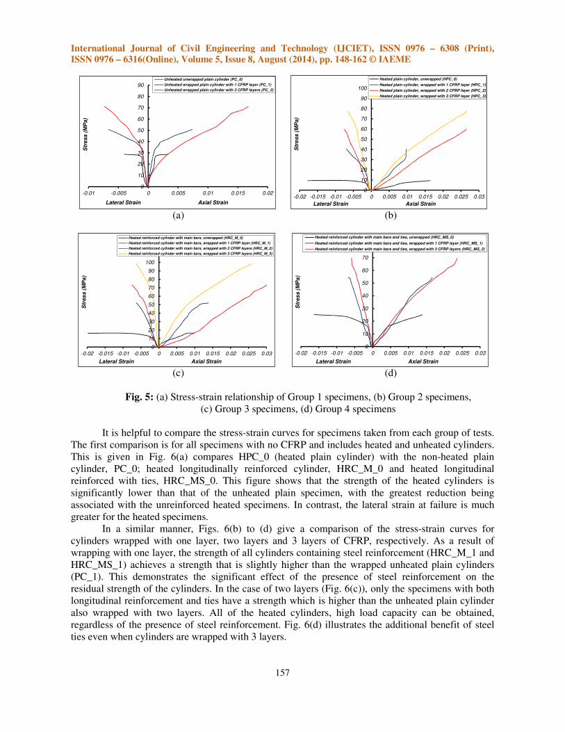
The stress-strain relationships have been derived from the load displacement measurements. In the case of longitudinal strain, this has been calculated by dividing the measured displacement by the gauge length. The lateral strain was calculated by dividing the average lateral displacement by the diameter of the cylinder. These relationships are shown in Figs. 5(a) to (d) for cylinders in Groups 1, 2, 3 and 4. It can be noted from these figures that the shape of the relationships change depending on the presence or absence of CFRP layers and the number of layers. This is true for both plain and RC concretes cylinders.
As a result of wrapping, the slope of the last portion of the stress-strain relationships is increased and failure usually occurs at a larger axial strain value compared with the unwrapped control specimens. This increase in the failure strain is a function of the number of CFRP layers applied to the concrete. There is also a difference in the behavior of heated and unheated concretes in relation to lateral strain. In unheated specimens the lateral strain at failure increases as a result of the addition of CFRP (see Fig. 5(a)). However, in the case of the heated specimens the lateral failure strain reduces (see Figs. 5(b) to (d)), but not all results change with further addition of CFRP layers.
International Journal of Civil Engineering and Technology (IJCIET), ISSN 0976 – 6308 (Print),
ISSN 0976 – 6316(Online), Volume 5, Issue 8, August (2014), pp. 148-162 © IAEME
157
(a) (b)
(c) (d)
Fig. 5: (a) Stress-strain relationship of Group 1 specimens, (b) Group 2 specimens, (c) Group 3 specimens, (d) Group 4 specimens
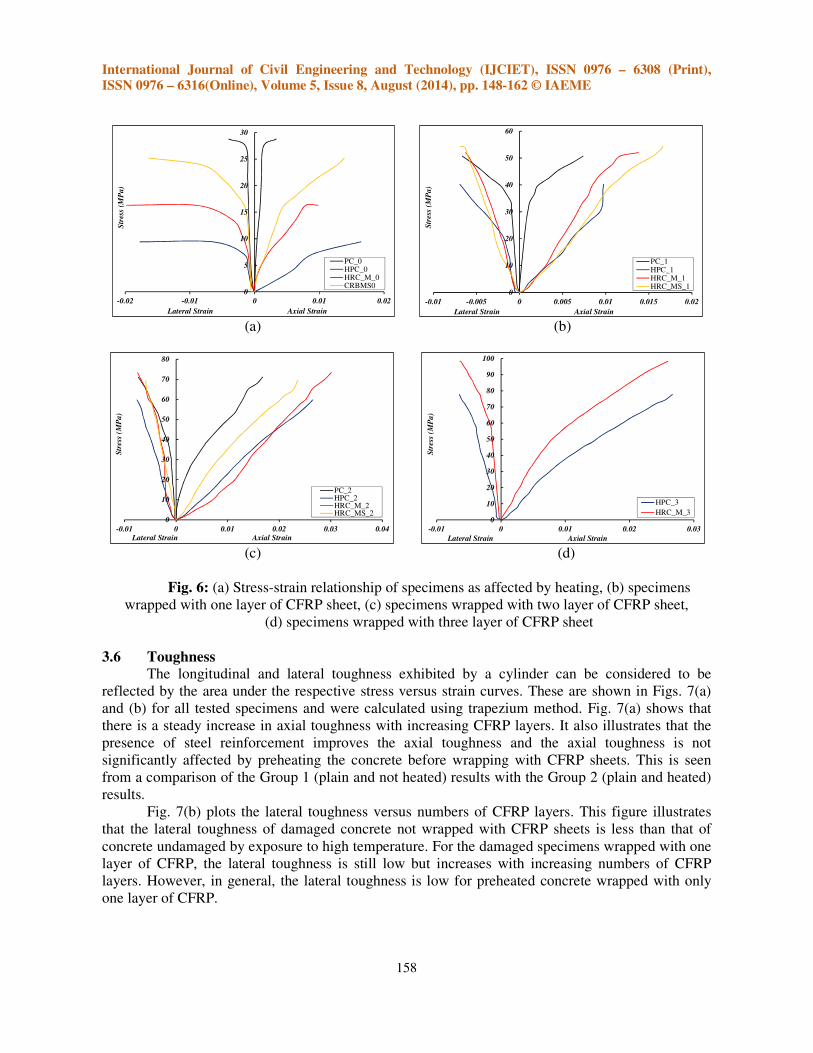
It is helpful to compare the stress-strain curves for specimens taken from each group of tests.
The first comparison is for all specimens with no CFRP and includes heated and unheated cylinders. This is given in Fig. 6(a) compares HPC_0 (heated plain cylinder) with the non-heated plain cylinder, PC_0; heated longitudinally reinforced cylinder, HRC_M_0 and heated longitudinal reinforced with ties, HRC_MS_0. This figure shows that the strength of the heated cylinders is significantly lower than that of the unheated plain specimen, with the greatest reduction being associated with the unreinforced heated specimens. In contrast, the lateral strain at failure is much greater for the heated specimens.
In a similar manner, Figs. 6(b) to (d) give a comparison of the stress-strain curves for cylinders wrapped with one layer, two layers and 3 layers of CFRP, respectively. As a result of wrapping with one layer, the strength of all cylinders containing steel reinforcement (HRC_M_1 and HRC_MS_1) achieves a strength that is slightly higher than the wrapped unheated plain cylinders (PC_1). This demonstrates the significant effect of the presence of steel reinforcement on the residual strength of the cylinders. In the case of two layers (Fig. 6(c)), only the specimens with both longitudinal reinforcement and ties have a strength which is higher than the unheated plain cylinder also wrapped with two layers. All of the heated cylinders, high load capacity can be obtained, regardless of the presence of steel reinforcement. Fig. 6(d) illustrates the additional benefit of steel ties even when cylinders are wrapped with 3 layers.
0
10
20
30
40
50
60
70
80
90
-0.01 -0.005 0 0.005 0.01 0.015 0.02
Str
ess
(M
Pa)
Lateral Strain Axial Strain
Unheated unwrapped plain cylinder (PC_0)
Unheated wrapped plain cylinder with 1 CFRP layer (PC_1)
Unheated wrapped plain cylinder with 2 CFRP layers (PC_2)
0
10
20
30
40
50
60
70
80
90
100
-0.02 -0.015 -0.01 -0.005 0 0.005 0.01 0.015 0.02 0.025 0.03
Str
ess
(M
Pa)
Lateral Strain Axial Strain
Heated plain cylinder, unwrapped (HPC_0)
Heated plain cylinder, wrapped with 1 CFRP layer (HPC_1)
Heated plain cylinder, wrapped with 2 CFRP layer (HPC_2)
Heated plain cylinder, wrapped with 3 CFRP layer (HPC_3)
0
10
20
30
40
50
60
70
80
90
100
110
120
-0.02 -0.015 -0.01 -0.005 0 0.005 0.01 0.015 0.02 0.025 0.03
Str
es
s (
MP
a)
Lateral Strain Axial Strain
Heated reinforced cylinder with main bars, unwrapped (HRC_M_0)
Heated reinforced cylinder with main bars, wrapped with 1 CFRP layer (HRC_M_1)
Heated reinforced cylinder with main bars, wrapped with 2 CFRP layers (HRC_M_2)
Heated reinforced cylinder with main bars, wrapped with 3 CFRP layers (HRC_M_3)
0
10
20
30
40
50
60
70
80
-0.02 -0.015 -0.01 -0.005 0 0.005 0.01 0.015 0.02 0.025 0.03
Str
es
s (
MP
a)
Lateral Strain Axial Strain
Heated reinforced cylinder with main bars and ties, unwrapped (HRC_MS_0)
Heated reinforced cylinder with main bars and ties, wrapped with 1 CFRP layer (HRC_MS_1)
Heated reinforced cylinder with main bars and ties, wrapped with 2 CFRP layers (HRC_MS_2)
International Journal of Civil Engineering and Technology (IJCIET), ISSN 0976 – 6308 (Print),
ISSN 0976 – 6316(Online), Volume 5, Issue 8, August (2014), pp. 148-162 © IAEME
158
(a) (b)
(c) (d)
Fig. 6: (a) Stress-strain relationship of specimens as affected by heating, (b) specimens
wrapped with one layer of CFRP sheet, (c) specimens wrapped with two layer of CFRP sheet, (d) specimens wrapped with three layer of CFRP sheet
3.6 Toughness
The longitudinal and lateral toughness exhibited by a cylinder can be considered to be reflected by the area under the respective stress versus strain curves. These are shown in Figs. 7(a) and (b) for all tested specimens and were calculated using trapezium method. Fig. 7(a) shows that there is a steady increase in axial toughness with increasing CFRP layers. It also illustrates that the presence of steel reinforcement improves the axial toughness and the axial toughness is not significantly affected by preheating the concrete before wrapping with CFRP sheets. This is seen from a comparison of the Group 1 (plain and not heated) results with the Group 2 (plain and heated) results.
Fig. 7(b) plots the lateral toughness versus numbers of CFRP layers. This figure illustrates that the lateral toughness of damaged concrete not wrapped with CFRP sheets is less than that of concrete undamaged by exposure to high temperature. For the damaged specimens wrapped with one layer of CFRP, the lateral toughness is still low but increases with increasing numbers of CFRP layers. However, in general, the lateral toughness is low for preheated concrete wrapped with only one layer of CFRP.
0
5
10
15
20
25
30
-0.02 -0.01 0 0.01 0.02
Str
ess
(MP
a)
Lateral Strain Axial Strain
PC_0HPC_0HRC_M_0CRBMS0
0
10
20
30
40
50
60
-0.01 -0.005 0 0.005 0.01 0.015 0.02
Str
ess
(M
Pa
)
Lateral Strain Axial Strain
PC_1HPC_1HRC_M_1HRC_MS_1
0
10
20
30
40
50
60
70
80
-0.01 0 0.01 0.02 0.03 0.04
Str
ess
(M
Pa
)
Lateral Strain Axial Strain
PC_2HPC_2HRC_M_2HRC_MS_2
0
10
20
30
40
50
60
70
80
90
100
-0.01 0 0.01 0.02 0.03
Str
ess
(M
Pa
)
Lateral Strain Axial Strain
HPC_3
HRC_M_3

International Journal of Civil Engineering and Technology (IJCIET), ISSN 0976 – 6308 (Print),
ISSN 0976 – 6316(Online), Volume 5, Issue 8, August (2014), pp. 148-162 © IAEME
159
(a) (b)
Fig. 7: (a) Variation of axial toughness with CFRP layer,
(b)Variation of lateral toughness with CFRP layer
3.7 Failure modes
Typical failure modes of the control and wrapped test specimens are shown in Fig. 8. The failure mode for cylinders not confined by CFRP exhibited, prior to failure, vertical cracking starting from the top of the cylinders and propagating downward along the length of the cylinders in the direction of loading. These cylinders failed by splitting as the result of shear stresses, as shown in Fig. 8. The maximum compressive load of these specimens was achieved shortly after cracks developed and propagated with a corresponding rapid reduction in load resistance.
In the case of the cylinders confined by CFRP, the failure mode depended on the lateral confining pressure. All wrapped concrete specimens failed by tensile rupture of the CFRP wrap in the column mid-height region in a sudden explosive manner (sudden fracture) with loud acoustic emission as the CFRP wrapping experienced excessive tension in the hoop direction, as seen in Fig.8.This is the most common failure pattern observed in CFRP/epoxy/concrete systems at normal ambient circumstances. None of the confined concrete specimens failed at the lap location of the CFRP wrapping demonstrating adequate load transfer at the lapped joint. The failed CFRP wrapping had concrete bonded to it after failure, indicating adequate adhesion and proper load transfer between the CFRP and concrete substrate. Confined concrete cylinders resisted load beyond failure of the concrete core as a result of the CFRP confinement actively provided lateral support.
Specimens confined with one layer of CFRP fabric lost strength suddenly due to rupture of the CFRP. On the other hand, the strength loss was gradual, in more than one step, with rupture of different layers for cylinders wrapped with 2 or 3 layers. After removal of the ruptured wrap post-test, the severely crushed state of the concrete was evident and the concrete failure plane was generally conical. For the CFRP-confined cylinders, the stirrup steel was found to have fractured due to buckling of the longitudinal steel bars.
0
5
10
15
20
25
30
0 1 2 3
Ax
ial T
ou
gh
ness
(k
N.m
m/m
m)
No. of CFRP Layers
Unheated wrapped plain cylinder (PC)
Heated wrapped plain cylinder (HPC)
Heated wrapped RC cylinder with main bars (HRC_M)
Heated wrapped RC cylinder with main bars and ties (HRC_MS)
0
1
2
3
4
5
6
7
8
0 1 2 3
La
teral T
ou
gh
ness
(k
N.m
m/m
m)
No. of CFRP Layers
Unheated wrapped plain cylinder (PC)Heated wrapped plain cylinder (HPC)Heated wrapped RC cylinder with main bars (HRC_M)Heated wrapped RC cylinder with main bars and ties (HRC_MS)

International Journal of Civil Engineering and Technology (IJCIET), ISSN 0976 – 6308 (Print),
ISSN 0976 – 6316(Online), Volume 5, Issue 8, August (2014), pp. 148-162 © IAEME
160
Fig. 8: Failure patterns of specimens and CFRP rupture
4. CONCLUSION
The following conclusions can be drawn based on the results of the present experimental
study:
1. Heating of concrete to elevated temperatures followed by air cooling, as experienced in real fires, can have a very significant effect on the residual properties of the concrete. Heating to 500°C for one hour resulted in a 67.4% reduction in axial strength for plain concrete but was less for concrete reinforced with steel either longitudinally or laterally.
2. CFRP sheets can be used to repair concrete damaged by exposure to high temperature. Compared with a non-heated unwrapped cylinder-PC_0 (Group 1), the residual compressive strength ratios were found to be 76.04% and 146.88% as a result of wrapping with one and two layers of CFRP, respectively. There is a proportional increase in the percentages of residual compressive strength with the number of CFRP sheet layers for all other Groups.
3. The presence of axial reinforcement and/or ties reduces the impact of heating on the residual strength of a compression member, however a significant (although lesser) loss of strength occurs. The addition of CFRP layers can enhance the strength and ductility of such temperature damaged members.
4. The lateral toughness of damaged concrete not wrapped with CFRP sheets is less than that of concrete undamaged by exposure to high temperature. Also the addition of CFRP layers increases the axial toughness with this increase being proportional to the number of layers.
5. All wrapped concrete specimens failed by tensile rupture of the CFRP wrap almost in the column mid-height region in a sudden explosive manner.

International Journal of Civil Engineering and Technology (IJCIET), ISSN 0976 – 6308 (Print),
ISSN 0976 – 6316(Online), Volume 5, Issue 8, August (2014), pp. 148-162 © IAEME
161
5. ACKNOWLEDGEMENTS
The tests described in this paper were carried out in the Department of Civil Engineering of
the School of Engineering in the Faculty of Engineering and Applied Science at the University of Duhok (UoD) in the Iraqi Kurdistan Region. Thanks are due to all demonstrators in the Civil Engineering Department at UoD for their role in collecting the experimental data.
REFERENCES
[1] Ilki A, Kumbasar N, Koc V. Strength and deformability of low strength concrete confined by carbon fiber composite sheets. Proceedings of the 15th ASCE engineering mechanics conference, New York, On CD Paper, no 101, 2002.
[2] Green MF, Bisby LA, Fam AZ, Kodur VKR. FRP confined concrete columns: Behaviour under extreme conditions. Cement and Concrete Composites. 2006; 28(10):928-37.
[3] Chowdhury EU, Bisby LA, Green MF, Kodur VKR. Investigation of insulated FRP-wrapped reinforced concrete columns in fire. Fire Safety Journal. 2007; 42(6-7):452-60.
[4] Lea F. The effect of temperature on some of the properties of materials. Engineering. 1920; 110(3):293-8.
[5] Lea F, Stradling R. The resistance to fire of concrete and reinforced concrete. Engineering. 1922; 114(2959):341-4, 38-82.
[6] Malhotra HL. The effect of temperature on the compressive strength of concrete. Magazine of Concrete Research. 1956; 8(23):85.
[7] Mohamedbhai GTG. Residual strength of reinforced concrete members subjected to elevated temperatures. Proceedings of the Institution of Civil Engineers (London). 1982; 73(pt 2): 407-20.
[8] Schneider U. Concrete at high temperatures - A general review. Fire Safety Journal. 1988; 13(1):55-68.
[9] Khoury GA. Compressive strength of concrete at high-temperatures - A reassessment. Magazine of Concrete Research. 1992; 44(161):291-309.
[10] Khoury GA. Effect of fire on concrete and concrete structures. Progress in Structural Engineering and Materials. 2000; 2(4):429-47.
[11] Xiao J, König G. Study on concrete at high temperature in China - An overview. Fire Safety Journal. 2004; 39(1):89-103.
[12] Annerel E, Taerwe L. Approaches for the assessment of the residual strength of concrete exposed to fire. In Proc 2nd IntConfConc Repair, Rehabil Retrofit (ICCRRR08). Taylor & Francis, UK, 2009. p. 245-6.
[13] Bazant ZP, Kaplan MF. Concrete at high temperature: Material properties and mathematical modelsHarlow, England: Longman Group Limited, Essex 1996.
[14] ISO 834. Fire resistance tests – Elements of building construction: International Organization for Standardization, Geneva, Switzerland; 2012.
[15] Ali F, Nadjai A, Silcock G, Abu-Tair A. Outcomes of a major research on fire resistance of concrete columns. Fire Safety Journal. 2004; 39(6):433-45.
[16] Arioz O. Effects of elevated temperatures on properties of concrete. Fire Safety Journal. 2007; 42(8):516-22.
[17] Chan YN, Peng GF, Anson M. Residual strength and pore structure of high-strength concrete and normal strength concrete after exposure to high temperatures. Cement and Concrete Composites. 1999; 21(1):23-7.

International Journal of Civil Engineering and Technology (IJCIET), ISSN 0976 – 6308 (Print),
ISSN 0976 – 6316(Online), Volume 5, Issue 8, August (2014), pp. 148-162 © IAEME
162
[18] Saafi M. Effect of fire on FRP reinforced concrete members. Composite Structures. 2002; 58(1):11-20.
[19] Lau A, Anson M. Effect of high temperatures on high performance steel fibre reinforced concrete. Cement and Concrete Research. 2006; 36(9):1698-707.
[20] Youssef MA, Moftah M. General stress-strain relationship for concrete at elevated temperatures. Engineering Structures. 2007; 29(10):2618-34.
[21] Ji G, Li G, Li X, Pang SS, Jones R. Experimental study of FRP tube encased concrete cylinders exposed to fire. Composite Structures. 2008; 85(2):149-54.
[22] Poon CS, Shui ZH, Lam L. Compressive behavior of fiber reinforced high-performance concrete subjected to elevated temperatures. Cement and Concrete Research. 2004; 34(12):2215-22.
[23] Bisby LA, Chen JF, Li SQ, Stratford TJ, Cueva N, Crossling K. Strengthening fire-damaged concrete by confinement with fibre-reinforced polymer wraps. Engineering Structures. 2011; 33(12):3381-91.
[24] Yaqub M, Bailey CG. Repair of fire damaged circular reinforced concrete columns with FRP composites. Construction and Building Materials. 2011; 25(1):359-70.
[25] Iraqi Standard Specification No.5. Properties of ordinary portland cement. Baghdad, Iraq: Central Apparatus for Standardization and Control1984.
[26] ASTM/C33. Standard specification for concrete aggregate. Annual book of ASTM standard, American Society for Testing and Material, Philadelphia. 2003.
[27] ASTM/C470. Specification for molds for forming concrete test cylinders vertically. American Society for Testing and Materials, west Conshohocken Pennsylvania.2002.
[28] ASTM/C192. Method of making and curing concrete test specimens in the laboratory. American Society for Testing and Materials, west Conshohocken Pennsylvania.2002.
[29] ASTM/C617. Standard practice for capping cylindrical concrete specimens. American Society for Testing and Materials, west Conshohocken Pennsylvania.2003.