beetle netpos - diebold nixdorf ag · beetle netpos and thus implement a wide range of expansion...
TRANSCRIPT

BEETLE NetPOS
Modular POS System
User Guide
Edition November 2000

Copyright© Wincor Nixdorf GmbH & Co. KG, 2000
The reproduction, transmission or use of this document or its contents is not
permitted without express authority.
Linux™ is a registered trademark of Linus Torvalds
Pentium™ is a registered trademark of the Intel CorporationMS-DOS™, Windows 95™, Windows 98™, Windows NT™ and Windows CE™ are
registered trademarks of the Microsoft CorporationBEETLE™ is a registered trademark of Wincor Nixdorf GmbH & Co. KG

Contents
Manufacturers Certification . . . . . . . . . . . . . . . . 1Tested Safety . . . . . . . . . . . . . . . . . . . . . . . . . . . . . . . 1FCC-Class A Declaration . . . . . . . . . . . . . . . . . . . . . . . . . 1Important notes . . . . . . . . . . . . . . . . . . . . . . . . . . . . . . 2
Introduction . . . . . . . . . . . . . . . . . . . . . . . . 4About this manual . . . . . . . . . . . . . . . . . . . . . . . . . . . . . 5Care of the BEETLE NetPOS . . . . . . . . . . . . . . . . . . . . . . . 5Recycling the BEETLE NetPOS . . . . . . . . . . . . . . . . . . . . . . 6Warranty. . . . . . . . . . . . . . . . . . . . . . . . . . . . . . . . . . 7
BEETLE NetPOS . . . . . . . . . . . . . . . . . . . . . 8Overview . . . . . . . . . . . . . . . . . . . . . . . . . . . . . . . . . 8
BEETLE NetPOS Peripherals . . . . . . . . . . . . . . . . . . . . . 9BEETLE NetPOS in a network . . . . . . . . . . . . . . . . . . . . 10
Before switching on the System . . . . . . . . . . . . . . . . . . . . . 11Unpacking and checking the System . . . . . . . . . . . . . . . . . 11Setting up the device . . . . . . . . . . . . . . . . . . . . . . . . . 11Cabling of the BEETLE NetPOS . . . . . . . . . . . . . . . . . . . 11Disconnecting cables . . . . . . . . . . . . . . . . . . . . . . . . . 12Mounting the cable cover . . . . . . . . . . . . . . . . . . . . . . . 13Connecting to the mains power supply . . . . . . . . . . . . . . . . 14Basic settings . . . . . . . . . . . . . . . . . . . . . . . . . . . . . 14Adjusting the loudspeaker. . . . . . . . . . . . . . . . . . . . . . . 15Light emitting diode (LED) . . . . . . . . . . . . . . . . . . . . . . 15
Connecting peripherals . . . . . . . . . . . . . . . . . . . . . . . . . 15Keyboard (KYBD) . . . . . . . . . . . . . . . . . . . . . . . . . . . 16Scanners and scales (COM1 - COM4*) . . . . . . . . . . . . . . . . 16Customer display (COM2* or COM4*) . . . . . . . . . . . . . . . . 17Cashier display (COM3*) . . . . . . . . . . . . . . . . . . . . . . . 17Monitor . . . . . . . . . . . . . . . . . . . . . . . . . . . . . . . . 17TFT - LCD display. . . . . . . . . . . . . . . . . . . . . . . . . . . 18Connecting standard PC peripherals (COM1) . . . . . . . . . . . . 18Network . . . . . . . . . . . . . . . . . . . . . . . . . . . . . . . . 19Modular printers . . . . . . . . . . . . . . . . . . . . . . . . . . . 19Cash drawer (1,2) . . . . . . . . . . . . . . . . . . . . . . . . . . . 20

BEETLE NetPOS - the components . . . . . . . . . . . 21Overview . . . . . . . . . . . . . . . . . . . . . . . . . . . . . . . . . 21Floppy disk drive . . . . . . . . . . . . . . . . . . . . . . . . . . . . . 23
General . . . . . . . . . . . . . . . . . . . . . . . . . . . . . . . . 23Inserting a disk . . . . . . . . . . . . . . . . . . . . . . . . . . . . 24Removing a disk . . . . . . . . . . . . . . . . . . . . . . . . . . . 24
Power Supply . . . . . . . . . . . . . . . . . . . . . . . . . . . . . . 24
Configuration variants . . . . . . . . . . . . . . . . . . 26Submodules for the CPU. . . . . . . . . . . . . . . . . . . . . . . . . 26
LAN controller 10/100 Mbit (PCI) . . . . . . . . . . . . . . . . . . . 26CRT- or TFT-adapter . . . . . . . . . . . . . . . . . . . . . . . . . 26Installing the submodules when using a TFT/CRT adapter. . . . . . 27Installing the submodules . . . . . . . . . . . . . . . . . . . . . . . 28
Change of the hard disk . . . . . . . . . . . . . . . . . . . . . . . . . 29
Retail Software . . . . . . . . . . . . . . . . . . . . . . 30Wincor Nixdorf store solutions . . . . . . . . . . . . . . . . . . . . . . 30Platforms and products . . . . . . . . . . . . . . . . . . . . . . . . . 31
Microsoft . . . . . . . . . . . . . . . . . . . . . . . . . . . . . . . 31Linux . . . . . . . . . . . . . . . . . . . . . . . . . . . . . . . . . 32Technology evaluation . . . . . . . . . . . . . . . . . . . . . . . . 32
Starting up the system. . . . . . . . . . . . . . . . . . 33Start and runup behaviour . . . . . . . . . . . . . . . . . . . . . . . . 33
Appendix . . . . . . . . . . . . . . . . . . . . . . . . . 36Technical data for the BEETLE NetPOS. . . . . . . . . . . . . . . . . 36Installation BA7x on NetPOS . . . . . . . . . . . . . . . . . . . . . . 37
Supplement . . . . . . . . . . . . . . . . . . . . . . . . . . . . . . 40Glossary . . . . . . . . . . . . . . . . . . . . . . . . . . . . . . . . . 41Abbreviations. . . . . . . . . . . . . . . . . . . . . . . . . . . . . . . 43

Manufacturers Certification
The device complies with the requirements of the EECdirective 89/336/EEC with regard to ‘Electromagneticcompatibility" and 73/23/ECC “Low Voltage Directive”.
Therefore, you will find the CE mark on the device or packaging.
Tested Safety
The POS system has been provided with the symbol for“Tested Safety”.
In addition, the BEETLE has received the UL symbol and cULsymbol.
FCC-Class A Declaration
This equipment has been tested and found to comply with the limits for aClass A digital device, pursuant to part 15 of the FCC Rules. These limitsare designed to provide reasonable protection against harmful interferencewhen the equipment is operated in a commercial environment. Thisequipment generates, uses, and can radiate radio frequency energy and, ifnot installed and used in accordance with the instruction manual, maycause harmful interference to radio communications.
Operation of this equipment in a residential area is likely to cause harmfulinterference in which case the user will be required to correct theinterference at his own expense.
Le présent appareil numérique ne génère pas de bruits radioélectriquesdépassant les limites applicable aux appareils numériques de la “Class A”prescrites dans le Règlement sur le brouillage radioélectrique édicté par leministère des Communications du Canada.
1
TESTED SAFETY
geprüfteSicherheit

Important notes
The modular POS system BEETLE NetPOS conforms to the current safetystandards for data processing equipment.
If this device is taken from a cold environment into the operating room,moisture condensation may form. The device must be absolutely dry beforebeing put into service; an acclimatization period of at least two hours musttherefore be observed.
� This device is equipped with a safety-tested power cable and may beconnected only to a prescribed grounded-contact power socket.
� When setting up the device, ensure that the power socket on the deviceand the grounded-contact power socket are easily accessible.
� To disconnect the device from the supply voltage completely, switch offthe device and disconnect the power plug.
� Ensure that no foreign objects (c.g. office clips) find their way into thedevice, as this may lead to electric shocks or short-circuits.
� Never plug in or unplug data communication lines duringthunderstorms.
� Protect devices from vibrations, dust, moisture and heat.
� Always dispose of used parts, such as batteries, in an environmentallysafe manner.
� The lithium battery must be disposed of in accordance with localregulations for special waste.
� In emergencies (e.g. damaged housing or damaged power cable,penetration by liquids or foreign bodies), the device must be switchedoff immediately, the power plug disconnected and the CustomerService of Wincor Nixdorf (WN) or your dealer must be notified.
� The device may only be repaired by authorized qualified personnel.Unauthorized opening of the device and inexpertly carried-out repairsmay not only seriously jeopardize the safety of the user, but also cancelall warranty and liability agreements.
IMPORTANT NOTES
2

� You should connect your BEETLE or other IT-devices only to poersupply systems with serarately guided protective earth conductor (PE).This kind of electricity system is known as TN-S network. Do not usePEN conductors!
� Please also observe the recommendations of the norm DIN VDE 0100,Part 540, Appendix C2 as well as EN50174-2, §5.4.3. Thus you canhelp to avoid possible malfunctions.
3
IMPORTANT NOTES

Introduction
The BEETLE NetPOS is the compact, powerful and economical basis foryour POS system.
The BEETLE conforms to the PC industry standard. Powerful processorsensure a quick processing of all operations.
You can connect a variety of different peripheral devices to your BEETLEand even the choice of the software is not limited to a certain product.
Optional the BEETLE NetPOS can be equipped with a floppy disk drive or amemory card adapter, a hard disk or a compact flash.
This provides you with a considerable degree of flexibility when arrangingthe configuration of your POS system.
The BEETLE can also be connected to a network once an appropriatenetwork card has been installed.
In the event of a mains voltage failure, the version with battery andcorresponding software enables you to save the data by means of acontrolled program shutdown.
Whatever configuration you need: Wincor Nixdorf offers the right solution.So, whenever you want to expand your BEETLE NetPOS, please contactyour Wincor Nixdorf GmbH branch office or your dealer.
INTRODUCTION
4

About this manual
This manual describes the modular POS system BEETLE NetPOS.
This documentation is intended to help you work with the POS system andto serve as a reference work. The detailed table of contents help you findthe desired information quickly and easily.
The first section describes� everything you need to do before switching on the POS system and� how to connect peripherals to the BEETLE NetPOS.
The second section contains� a brief overview of the components of your BEETLE POS system.
Here, you will also find a detailed description of recurring actions, forexample, how to use the disks.
The third selection provides� a brief overview of the Wincor Nixdorf Retail Software.
The Appendix� contains the most important technical data, a glossary and a list of
abbreviations.
Notes in the manual are marked by this symbol.
This symbol is used for warnings.
The type and scope of application programs depend on the customer’s ownselection; therefore, software will not be discussed further in this manual.
Separate manuals are included in the scope of the connectable peripherals.For this reason, a more detailed description of these devices will not beprovided here. For more information, see the relevant manuals.
Care of the BEETLE NetPOS
Clean your BEETLE NetPOS at regular intervals with a suitableplastic-surface cleaner. Make sure that the power plug is disconnected,connector cables are unplugged and that no liquid finds its way into thedevice.
5
ABOUT THIS MANUAL

Recycling the BEETLE NetPOS
Environmental protection does not begin whenit comes time to dispose of the BEETLE; itbegins with the manufacturer. This product wasdesigned according to our internal norm“Environmental conscious product design anddevelopment”
The modular BEETLE NetPOS POS System is manufactured without theuse of CFCs and CCHS and is produced mainly from reusable componentsand materials.
The processed plastics can, for the most part, be recycled. Even theprecious metals can be recovered, thus saving energy and costly rawmaterials.
Please do not stick labels onto plastic case parts. This would help us tore-use components and material.
You can protect our environment by only switching on your equipment whenit is actually needed. If possible, even avoid the stand-by-mode as thiswastes energy, too. Also switch your equipment off when you take a longerbreak or finish your work.
At this time, there are still some parts that are not reusable. Wincor Nlxdorfguarantees the environmentally safe disposal of these parts in theRecycling Center, which is certified pursuant to ISO 9001.
So don’t simply throw your BEETLE POS system on the scrap heap when ithas served its time, but take advantage of the environmentally smart,up-to-date recycling methods!
Please contact your competent branch or the department environmentalprotection for information on how to return and re-use devices anddisposable materials under the following fax number:
Fax: +49 (0) 5251 8-18015
We look forward to your telephone call or your fax.
RECYCLING THE BEETLE NETPOS
6

Warranty
Wincor Nixdorf guarantees a limited warranty engagement for 12 monthsbeginning with the date of delivery. This warranty engagement covers allthose damages which occur despite a normal use of the product.
Damages because of
� Improper or insufficient maintenance,� Improper use of the product or unauthorized modifications of the
product,� Inadequate location or surroundings
will not be covered by the warranty.
All parts of the product which are subject to wear and tear are not includedin the warranty engagement. Please order spare parts at the Wincor Nixdorfcustomer service.
7
WARRANTY

BEETLE NetPOS
Overview
You can connect a variety of peripherals to your modular POS systemBEETLE NetPOS and thus implement a wide range of expansion stages.You can connect a two or four-line alphanumeric customer display and afour line cashier display. Alternatively you can connect Flat screens, suchas BA69 (VGA/4), BA70 (b/w) or BA71 and BA72 (color), use various typesof scanners such as distance, touch or stationary scanners, use scales andscanner scales (please take into account the official certificationregulations), connect various printers, use POS keyboards with or without aswipecard reader, use different types of cash drawers, connect a monitor,install the POS workplace SNIkey, integrate the BEETLE NetPOS in anetwork.
This means that the BEETLE NetPOS can meet your requirements at alltimes, without having to exchange the complete system for a new one, thussaving you time and money.
The illustration below show you how your modular POS system can grow -from a scanner to integration in a network.
8

BEETLE NetPOS Peripherals
9
OVERVIEW
PrinterScanner
Cash drawer
Scales
MonitorFlatscreendisplay
Keyboard
BA69
Customer or cashier display
SNIkey

BEETLE NetPOS in a network
OVERVIEW
10
Ethernet 10/100 Base TServer
BEETLE NetPOS

Before switching on the System
Unpacking and checking the System
Unpack the parts and check to see whether the delivery matches theinformation on the delivery note.
The carton contains the basic unit and a country-specific accessories kit.Some ordered composition may be installed.
If damage has occurred during shipping or if the package contents do notmatch the delivery note, promptly inform your Wincor Nixdorf sales outlet.
Transport the device only in its original packaging (to protect it againstimpact and shock).
Setting up the device
Set up the BEETLE NetPOS POS system where it will not be exposed toextreme environmental conditions. Protect the device from vibrations, dust,moisture, heat and strong magnetic fields.
Make sure that the side ventilation slots on the BEETLE NetPOS and theexternal power supply are not obstructed in order to ensure that the devicehas sufficient ventilation.
Cabling of the BEETLE NetPOS
Follow the steps below in the order given when installing devices:
� The cable cover must be removed, if present.
� Plug one end of the power cable into the external power supply andconnect the other end to the main power supply.
� Plug one end of the other power cable into a grounded-contact powersocket of the external power supply and the other into the socket of theBEETLE NetPOS.
� Plug in and secure the data cable.
11
BEFORE SWITCHING ON THE SYSTEM
Always make sure that the system is switched off when you do cablingworks.
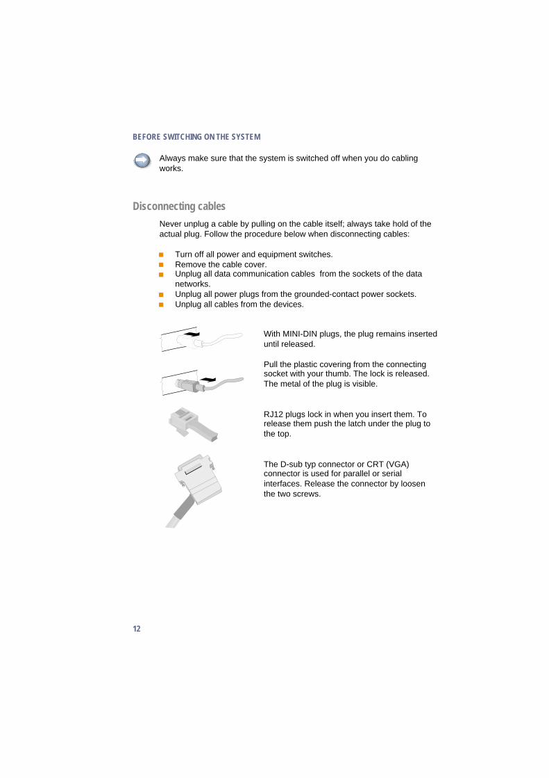
Disconnecting cables
Never unplug a cable by pulling on the cable itself; always take hold of theactual plug. Follow the procedure below when disconnecting cables:
� Turn off all power and equipment switches.� Remove the cable cover.� Unplug all data communication cables from the sockets of the data
networks.� Unplug all power plugs from the grounded-contact power sockets.� Unplug all cables from the devices.
With MINI-DIN plugs, the plug remains inserteduntil released.
Pull the plastic covering from the connectingsocket with your thumb. The lock is released.The metal of the plug is visible.
RJ12 plugs lock in when you insert them. Torelease them push the latch under the plug tothe top.
The D-sub typ connector or CRT (VGA)connector is used for parallel or serialinterfaces. Release the connector by loosenthe two screws.
BEFORE SWITCHING ON THE SYSTEM
12

Take hold of the USB connector housing andrelease the connection.
Loosen the plug of the USB powered connectorby pressing the plastic latch.
Release the TFT connector by pressing thelatches on the left and right inwards.
Mounting the cable cover
The scope of supply of your BEETLE NetPOS includes a cable cover.Before mounting the device, you should first remove the cable openingswhere necessary.Tools are not required as the plastic parts can be removed by hand.
In order to mount the cable cover, insert it in the guide � and turn it to theBEETLE box. Press from the inside against the exterior and pull it to the
13
BEFORE SWITCHING ON THE SYSTEM
�
�

rear side until it is fixed in the second pin � on the back of the BEETLE
box.
In doing so, ensure that the cable cover does not fit askew.
Connecting to the mains power supply
All devices belonging to the modular BEETLE NetPOS system that have aseparate power cable must be connected to the same electric circuit.
� Make sure that all data cables on the system unit and peripherals areconnected correctly.
� Make sure that the DC cable is connected to power supply and tosystem unit.
� Plug all power cables belonging to the BEETLE and the peripherals intothe grounded-contact power sockets.
You can now switch onthe BEETLE NetPOS bymeans of the switch onthe external powersupply. Push the ON/OFFbutton at the front of thebox.
The power supply can be connected to all standard power supply networks.The unit adjusts automatically to the respective voltage. The maximumoutput of the power pack is 150 W.
Basic settings
Ex works, the BEETLE NetPOS is configured to your order. Yourconfiguration must be subsequently adapted to support supplementarydevices such as scanners. For more information, contact the WN branchoffice responsible for your area.
BEFORE SWITCHING ON THE SYSTEM
14
ON/OFF button
ON/OFF switch

Adjusting the loudspeaker
You can set the volume as desired by means of a menu described in themanual “BEETLE POS Motherboard”, chapter “BIOS Setup”.
Light emitting diode (LED)
The left LED green (POWER) lights when theBEETLE NetPOS is switched on.
The right, yellow LED (HDD) lights up whilethe hard disk is being accessed.
Connecting peripherals
The peripherals mentioned here are available as options and are not part ofthe basic configuration. A separate manual is provided for each of theconnectable components. For more detailed information, please consult therelevant documentation.
The figure shows the back panel of the BEETLE NetPOS with the locationsof the connecting sockets and connecting plugs. If you wish to connect amonitor, however, you must also have a video board.
CRT and TFT interfaces are used alternatively.
Connecting peripherals with the system switched on is not allowed.
Rear panel of the BEETLE NetPOS
15
CONNECTING PERIPHERALS
KYBD COM1
VGA
COM4* COM3* COM2*USB LAN/ASYN
LPT1
SPKMIC
DC IN
Power Connector

Rear panel of the power supply
Keyboard (KYBD)
The BEETLE NetPOS has a 6-pin mini-DIN jack for connecting a keyboard.Make sure that the connector is plugged firmly into the socket to preventmalfunctioning. Power is supplied to the keyboard via this socket. If youwish to connect a standard PC keyboard with DIN connector, you must usea special adapter cable, obtainable from the WN branch office responsiblefor your area.
When removing cables with locks, please grip the cable at the connectorhousing.
Scanners and scales (COM1 - COM4*)
Depending on the systems configuration, scanners without an independentpower supply are connected to the COM2*, COM3* or COM4* serialinterface (standard setting COM3). Connect scales with their own powersupply to the COM1 interface. COM1 is designed as a 9-pin D-sub plug,whereas COM2* - COM4* are 9-pin D-sub jacks.Make sure that the scanner connector is plugged securely into the socket toprevent possible malfunctioning.
If you connect scales to the BEETLE NetPOS which are not supplied byWincor Nixdorf, you must obtain a licence for the driver software.
CONNECTING PERIPHERALS
16
SubconnectorMains
0 I
DC 24V
100-120 V ~ 2A max.200-240 V ~ 1A max.
1 2cashdr only
ON/OFF Cash Drawer 1, 2POS Printer Power
Mains Socket

The COM2 interface is without effect if the onboard TFT adapter with touchscreen function is installed.
Customer display (COM2* or COM4*)
With the BEETLE NetPOS, and depending on the system´s configuration,the customer display is connected to either the COM2* or COM4* serialinterface. The interface connection is a 9-pin D-sub jack. Make sure that theconnector for the customer display is screwed firmly to the socket to preventpossible malfunctioning. Power is supplied via this jack.
Cashier display (COM3*)
Connect the cashier display to the serial interface COM3*. This port is a9-pin D-sub jack.
Make sure that the connector for the cashier display is screwed firmly to thesocket to prevent possible malfunctioning.
Monitor
If a CRT adapter is installed, you can connect a monitor to the system viathe 15-pin D-sub jack on the CRT adapter. The power supply of the monitoris done by the rubber socket of the external power pack. The socket issituated at the front of the power pack.
17
CONNECTING PERIPHERALS

A LCD screen can be connected alternatively if a TFT adapter is installed.
TFT - LCD display
If a TFT adapter is installed you can connect a SNIkeyTFT/ BA71/ BA72/BA73 to the BEETLE NetPOS without using an ISA slot. Connect the 50-pindata cable of the LCD to the system. The signals for the touch screenfunction and the power supply are also made via this cable. To implementthe touch screen functionality for the COM2 interface you have to changesome system settings ( see manual “BEETLE POS Motherboard”, chapter“Technical data”).
If the display is equipped with a keyboard cable connect this with the KYBDterminal. You can only connect one keyboard cable to the BEETLE NetPOSat a time - either that of the LCD or that of the free standing keyboard (e.g.PC keyboard, TA57, TA61)
To find out how to connect a second keyboard, refer to the user guide of thedisplay.
Connecting standard PC peripherals (COM1)
You can connect supplementary standard peripherals to theBEETLE NetPOS via the COM1 serial interface.
Make sure that all supplementary devices have been tested for RFIsuppression pursuant to the legal requirements of your country.
CONNECTING PERIPHERALS
18

Network
If a network board is installed, the system can be connected to a network(LAN) from the POS terminal back panel.
Modular printers
The standard parallel interface LPT1 is intended for connecting a printer.
Appropriate POS printers can also be connected via the low-voltage jack24V, max. 2A at the external power supply. A connecting cable with aHOSIDEN plug is required for this.
Do not connect the HOSIDEN plug when the system is turned on, this canlead to an automatic reboot of the system.
Connect only cable to the 24V connector which are marked with DP-1 orDP-2.
19
CONNECTING PERIPHERALS

Cash drawer (1,2)
The BEETLE NetPOS has two RJ12 sockets at the external power supplyfor connecting cash drawers. Make sure that the connector is plugged firmlyinto the socket to prevent malfunctioning. RJ12 plugs lock in when youinsert them. Power is supplied to the cash drawer via this socket,+24V +5% / -10%.
Connecting daisy chained cash drawers and 12V OEM-drawers isprohibited!
CONNECTING PERIPHERALS
20

BEETLE NetPOS - the components
Overview
The following figure shows the outside of the BEETLE NetPOS.
21
LEDs(POWER, HDD)
ON/OFF
Floppy Disk

The figure below shows the inside of the BEETLE NetPOS.
OVERVIEW
22
Floppy Disk
TFTAdapter
Hard Disk
SD RAM

Floppy disk drive
General
The BEETLE NetPOS is equipped with a floppy disk drive for 3.5" disks.The LED at the drive lights up whenever the system accesses the drive.
The disks can be used for a variety of applications, such as:
� Loading programs� Saving data (e.g. daily sales figures)� Access control (electronic key)
The disk can be write protected to protect your data from accidentally beingoverwritten. The slide is located at the bottom left of the diskette.
23
FLOPPY DISK DRIVE
Writing is possible
Writing is not possible

Inserting a disk
Hold the disk so that the arrow symbol is at the top and points away fromyou. Now insert the disk in the drive slot provided. The disk has beencorrectly inserted when the grey ejection button has popped out.
Removing a disk
Press the ejection button next to the drive slot. You can now remove thedisk.
Never remove the disk while the drive is being accessed, i.e. when the LEDindicator for the drive is illuminated. Otherwise, you could damage the driveand the disk.
Power Supply
The power supply automatically adjusts itself to the particular voltage. Thepower output of the power supply is maximum 150 W.
The power cord receptacle and the ON/OFF switch are located on the backof the power supply. At the front side of the BEETLE NetPOS you will findthe ON/OFF button which will turn on the system if the ON/OFF switch atthe rear side of the external power supply is in the position ON. Pushing theON/OFF button again (push at least 4 sec.) will turn the system into theStand by mode.
POWER SUPPLY
24
ejection button

Rear panel of the power supply
25
POWER SUPPLY
0 I
DC 24V
100-120 V ~ 2A max.200-240 V ~ 1A max.
1 2cashdr only
ON/OFF Cash Drawer 1, 2POS Printer Power
SubconnectorMains Mains Socket
ON/OFF button ON/OFF switch

Configuration variants
Submodules for the CPU
Various controllers can be plugged in on the CPU. The following is a briefdescription of the available options:
LAN controller 10/100 Mbit (PCI)
This controller can be used to incorporate the BEETLE NetPOS in anEthernet network (10/100 Base T). It uses the internal PCI bus.
CRT- or TFT-adapter
Both adapters must be installed alternatively. You can connect either a CRTmonitor or a TFT-LCD module with optional touch screen functionality.When installing a TFT adapter with touch screen functionality make surethat the internal loudspeaker will be taken off to activate the loudspeaker inthe screen display (see chapter installation in the manual of the screendisplay) and the touch functionality will be activated via jumper (see jumpersettings in the manual “BEETLE POS Motherboard”).The COM2 interface is no longer valid for external use. If the BEETLEsystem is pre-installed ex works, COM2 will delivered with a cover.
SUBMODULES FOR THE CPU
26

Installing the submodules when using a TFT/CRT adapter
First ensure that the system is switched off and that the power connector isdisconnected.Loosen the screws at the rear side (see arrows).
Then lift off the top cover.
When using a TFT or CRT adapter, loosen the screws on the rear side ofthe adapter (see arrows).
Loosen the connector of the adapter from the motherboard, loosen thescrews and shift the adapter through the open slot �. Remove the metalcover of the LAN/ASYNC interface �.
27
SUBMODULES FOR THE CPU
�
�

Plug in the submodule (see drawing).
Fix the submodule (here LAN controller) with two screws at the rear side ofthe BEETLE system � and push the TFT adapter or CRT adapter throughthe slide back in the right position�. After connecting it with themotherboard fix the adapter with the two screws.
Installing the submodules
Proceed according to the description in the section before, however withoutinstallation of the TFT or CRT adapter.
SUBMODULES FOR THE CPU
28
LAN Controller
�
�

Change of the hard disk
To change the hard disk open your BEETLE NetPOS as described on thepages before.
Pull out the connectors, lift up the hard disk� floppy disk.
Leverage the hard disk out of the guide rail. Loosen the screws and changethe hard disk. Fix the new hard disk with the screws. Shift the carrier of thehard disk into the guide until you hear a click.
Plug in the connectors again and close the cover. Plug the power cable(external power supply) and switch on the system.
29
CHANGE OF THE HARD DISK

Retail SoftwareThe market for retail store solutions presents a broad array of requirements
for the functions in these solutions as well as for the software technologies
used. Moreover, the software and hardware is used internationally, and
must meet a wide range of regional requirements. This means, for example,
that solutions that fulfill the regional requirements of Central Europe mayturn out to be inadequate for Asia or Latin America. Wincor Nixdorf provides
customers worldwide with standard products appropriate to the commercial
and technical complexity of their organizations. In keeping with this strategy,
Wincor Nixdorf has defined a portfolio of in-store solutions that
accommodates this variety of requirements. The portfolio offers in-storesolutions for the different operating system platforms that are prominently
used worldwide (Microsoft and Linux), and also offers varying degrees of
solution complexity. Besides demanding products that will remain viable in
the future, today’s retail customers also require that a solution provider offer
other services, such as project management, customization and integrationservices, as well as advice in the selection of basic core technologies.
Wincor Nixdorf store solutions
As an international product provider, we are oriented to marketdevelopments and standards that are available worldwide, allowing us to
offer our customers open solutions and services with guaranteed viability
into the future.
Software must of course meet the customers’ needs, and these can oftenvary greatly. But for the software to be a long-term success, its design and
implementation must also take into account the fundamental trends and
standards that are emerging in the market. Only if you stay open to the
dynamics of retail, it can be ensured that new commercial trends will be
reflected within the scope of the solutions provided. To accommodate thesedynamics, Wincor Nixdorf must have the appropriate technical expertise.
When working on product development, projects or consulting, this
expertise is essential to effectively meet current as well as future
requirements.
WINCOR NIXDORF STORE SOLUTIONS
30

Platforms and products
Solution platforms today are expected to utilize state-of-the-art,standardized operating systems. Some of the decisive factors in selecting
an operating system in the retail trade include:
� An operating system should provide software administration
mechanisms to help minimize the total cost of ownership� The flexibility of an operating system for use with different hardware
and peripherals� Global availability to ensure complete coverage, as well as� Scalability with regard to user requirements.
In light of these criteria, the Microsoft operating systems have established
themselves in the market, and the Microsoft Windows NT platform is now
positioned as an important technological factor.
However, the growing discussion of operating system scalability, as well asthe demand for continued reduction of the total cost of ownership, have led
to the emergence of other operating systems. The strongest trend has been
to Linux. Regardless of the industry involved, Linux offers itself as an
interesting supplemement to the world of Microsoft.
In view of this trend, Wincor Nixdorf has defined a software strategy that
accommodates both Linux and the popular Microsoft platform:
Microsoft
Wincor Nixdorf currently offers two products for retail customers based on
the Microsoft platform - the successful POSition store solution and the
next-generation Trading Post software.
With POSition, Wincor Nixdorf offers an optimized solution for use in the
self-service food and self-service non-food market segments. It is a flexible
and highly integrative solution. Meeting the needs of its international
clientele, it is based on a client/server architecture with MS-DOS at the POSterminals and a Windows NT-based server.
Trading Post presents itself as an object-based POS solution which uses
the Microsoft Windows NT operating system throughout. Withstandardization concepts for interfacing POS peripherals (OPOS), an
31
PLATFORMS AND PRODUCTS

innovative, modular customizing concept and a graphical user interface at
the POS terminal, Trading Post is positioned in markets with demandingrequirements for system architecture and application versatility.
Linux
With CALYPSO, Wincor Nixdorf provides an international, high-performancesales system for the control and administration of sales activities in the
self-service food and self-service non-food market segments. It is based on
a Linux server and MS-DOS or Linux clients. The system architecture and
platform guarantee optimal security and performance. CALYPSO is one of
the first retail solutions with a homogenous Linux platform throughout.
Technology evaluation
The further development of Wincor Nixdorf retail solutions takes place in
dialog with its customers. Before being included in existing products, newtrends and technologies are carefully examined with regard to their
readiness for the market. To ensure market acceptance and market
orientation in the selection of technologies, Wincor Nixdorf conducts
technology evaluation projects with its customers and partners. This
significantly reduces technological risks.
PLATFORMS AND PRODUCTS
32

Starting up the systemThe configuration label shows you the equipment included in your modularBEETLE /NetPOS system.The label is located at the underside of the BEETLE /NetPOS. The dataspecified there are required for entering the setup parameters (see sectionSetup in the manual “BEETLE POS Motherboard”).
Start and runup behaviour
After installing the BEETLE /NetPOS, switch on the POS system using theON/OFF button on the front panel and the power switch on the powersupply.
The system first performs an automatic self-test to test its basic functions.
For example, you may see the following message (irrespective of processortype) on the four-line cashier display or on the monitor:
xx/xx is the place holder of the BIOS version number
The system then determines the medium from which the operating systemand POS application are to be booted. Each medium is assigned a logicaldrive according to the configuration of your BEETLE /NetPOS.
The following media can be assigned a drive:
� Disk� Network� Hard disk� Memory card� CD-ROM (not for BEETLE /NetPOS)
The logical drives are designated A:, B:, C: and D:.
33
START AND RUNUP BEHAVIOUR
WN POS xx/xx Date

If the system is to be booted from disk, this medium must always beassigned drive A:. The network is always assigned to the C: drive during therunup procedure. The hard disk can be assigned to the C: or D: drive. Thesystem can only be started from the hard disk if the disk has beenconfigured as the C: drive.
Corresponding to the Setup configuration the modular BEETLE /NetPOSPOS system can be booted from the following drives:
� Floppy disk in drive A:� Hard disk in drive C:� CDROM in EL TORITO format� Network adapter with BOOTPROM
Please mind that the storage medium must be system-boot-capable.
The following priorities apply:
Floppy disk (A:) High priority
Network (C:) Medium priority
Hard disk (C:) Low priority
As standard the POS system always attempts to boot from a disk first if it isinserted in the respective drive.
If the POS system does not find a disk resp. a CD-ROM in drive A:, itautomatically continues the loading process from drive C:.
If drive A: contains a disk on which no operating system is stored, the POSsystem cannot be booted. In this case, either replace the disk with one thatis system-boot-capable or remove the disk altogether.
The operating system responds with additional messages on the cashierdisplay or monitor, as shown in the illustration below.
START AND RUNUP BEHAVIOUR
34
C >P:

If the operating system has started up without error, the POS applicationsoftware is automatically booted if necessary.
A message is displayed as soon as the BEETLE /NetPOS is ready foroperation. For more detailed information, see the description of yourapplication program.
35
START AND RUNUP BEHAVIOUR

Appendix
Technical data for the BEETLE NetPOS
TECHNICAL DATA FOR THE BEETLE NETPOS
36
BoxWidth 288 mm 11.34 inDepth 255 mm 10.04 inHeight 58 mm 2.24 inCable cover 80 mm 3.15 in
Power SupplyWidth 162 mm 6.38 inDepth 223 mm 8.87 inHeight 80 mm 3.15 in
WeightBox approx. 3.5 kgPower supply approx. 2.5 kg
Climatic categoryOperating IEC 721-3-3 Class 3K3 +5°C to +40°CTransport IEC 721-3-2 Class 2K2 -25°Cto +60°CStorage IEC 721-3-1 Class 1K2 +5°C to +40°C
Input voltage 100 - 120 VAC200 - 240 VAC
Max. power consumption 3A: 200 - 240V5A: 100 - 120V
Frequency of system voltage 50 - 60 Hz

Installation BA7x on NetPOS
Loosen the screws �, slightly lift up the cover of the NetPOS � and pull outforward �.
Take the pre-mounted cover, put it on the NetPOS system and push it to therear. Fasten the screws.
37
INSTALLATION BA7X ON NETPOS
�
�
�
�
�

Open the cable cover of the display (see arrow) on the rear side andremove it. You see the cableconnection.
Put the grey connection part into the display swivel joint� and fix it withthe screw �.
Add the swivel joint into the mounting foot. Press your finger on the screw�, so that the grey connection part is in the back. Shift the display into themounting foot until A fits in B.
INSTALLATION BA7X ON NETPOS
38
�A B
�
�

Fasten the swivel joint at the display (see figure). Plug the cableconnection and reinsert the cable cover.
Tilt the display backwards. Set the locking noses of the impact-blind into thesupport angles of the swivel joint � and press the impact-blind until it islocked �.
Install the impact-blind to avoid injuries.
39
INSTALLATION BA7X ON NETPOS
�
�

Supplement
It is possible to lay an additional cable into the mounting foot beside thedisplay cable . Minimum distances are depending upon type of cable (�cable of swipe card reader,� cable of smart card reader, values ± 5 mmapply to BA70, BA71 and BA72).
INSTALLATION BA7X ON NETPOS
40
150 mm
140 mm
�
150 mm
320 mm
�

Glossary
BitA bit is a binary digit (0 or 1). It is the smallest unit used in data processing.
BPPBits per Pixel, depth of colour.
ControllerServes to control data input and output in a data processing system orbetween a computer and the connected peripherals.
CPUAbbreviation of central processing unit. It includes the main components ofa data processing system. The CPU monitors all operations and providesdata and programs. It comprises the control unit for input and output, thecomputer and the main memory, divided into ROM and immediate accessstorage.
InterfaceDesignates the transition point between different hardware units andsoftware units or between hardware and software units of computers or theirperipherals.
JEIDAAbbreviation of Japan Electronic Industry Development Association.Industry standard for memory cards.
Operating systemRefers to all programs that are a component of a computer and are requiredfor operating the system and executing application programs.
PCMCIAAbbreviation for Personal Computer Memory Card International Association.Industry standard for memory cards.
Plug and PLay (PnP)PnP means the automatic recognition of hardware components by thesystem. Thus the installation, integration and configuration of newcomponents is made substantially easier.
41
GLOSSARY

PeripheralsDevices serving as an input/output device or storage for a computer. Thisincludes, for example, document readers, keyboards, printers and diskstorage.
ServerThis is a computer connected to a local network and whose services areavailable to all of the network subscribers, e.g. a print server for printing thedata from all of the network subscribers on the printer connected to theserver.
VGAStands for Video Graphics Array and is the interface for connecting colourmonitors.
GLOSSARY
42

Abbreviations
AT Advanced TechnologyATA AT-AttachmentBIOS Basic Input Output SystemCOM Communication PortCPU Central Processing UnitCRT Cathode Ray TubecUL canada Underwriters LaboratoriesDIMM Dual Inline Memory ModuleECP Extended Capability PortEPP Enhanced Parallel PortEPROM Erasable Programmable Read Only MemoryFD Floppy DiskGS “Geprüfte Sicherheit” (Tested Safety)HDD Hard Disk DriveHFT High Frequency TableHSF Hash File Access MethodIDE Integrated Drive ElectronicISA Industrial Standard ArchitectureISO International Standardization OrganizationJEIDA Japan Electronic Industry Development AssociationLAN Local Area NetworkLBA Logical Block AddressingLED Light Emitting DiodeLPT Line PrinterOEM Original Equipment ManufacturesPCI Peripheral Component InterconnectPCMCIA Personal Computer Memory Card Intern. AssociationPnP Plug and PlayRAM Random Access MemoryROM Read Only MemorySCSI Small Computer Systems InterfaceSD RAM Synchronous Dynamic Random Access MemorySIMM Single In Line Memory ModuleSRAM Static Random Access MemorySVGA Super Video Graphics ArrayTFT Thin Film TransistorUPS Unbreakable Power SupplyUL Underwriters LaboratoriesUSB Universal Serial BusXMS Extended Memory Specification
43
ABBREVIATIONS