bedienungsanleitung user’s manual advanced-h40d manuel d...
TRANSCRIPT

Germ
anEnglish
FrenchItalian
BedienungsanleitungUser’s manual
Manuel d’utilisationManuale utente
Ver. 1.0
Design-Satellitenantenne mit einer dual-linearen Polarisation
Advanced-H40D Series
Advanced-H40D Series

Germ
anInhalt
Um was handelt es sich bei der HUMAX Advanced-H40D?. . . . . . . . . . . . . . . . . . . . . . . . . . . . . . . . . . . . . . . . . . . . . . . . . .Um was handelt es sich bei der HUMAX Advanced-H40D 2|
Sicherheitsanweisungen. . . . . . . . . . . . . . . . . . . . . . . . . . . . . . . . . . . . . . . . . . . . . . . . . . . . . . . . . . . . . . . . . . . . . . . . . . . . . . . . . . . .Sicherheitsanweisungen 2|
Lieferumfang. . . . . . . . . . . . . . . . . . . . . . . . . . . . . . . . . . . . . . . . . . . . . . . . . . . . . . . . . . . . . . . . . . . . . . . . . . . . . . . . . . . . . . . . . . . . . . . .Lieferumfang 3|
So wird sie installiert?. . . . . . . . . . . . . . . . . . . . . . . . . . . . . . . . . . . . . . . . . . . . . . . . . . . . . . . . . . . . . . . . . . . . . . . . . . . . . . . . . . . . . . . .
. . . . . . . . . . . . . . . . . . . . . . . . . . . . . . . . . . . . . . . . . . . . . . . . . . . . . . . . . . . . . . . . . . . .
. . . . . . . . . . . . . . . . . . . . . . . . . . . . . . . . . . . . . . . . . . . . . . . . . . . . . . . . . . . . . . . . . . . . . . .
. . . . . . . . . . . . . . . . . . . . . . . . . . . . . . . . . . . . . . . . . . . . . . . . . . . . . . . . . . . . . . . . . . . . . . . . . . . .
. . . . . . . . . . . . . . . . . . . . . . . . . . . . . . . . . . . . . . . . . . . . .
. . . . . . . . . . . . . . . . . . . . . . . . . . . . . . . . . . . . . . . . . . . . . . . .
. . . . . . . . . . . . . . . . . . . . . . . . .
. . . . . . . . . . . . . . . . . . . . . . . . . . . . . . . . . . . . . . . . . . . . . . . . . . . .
. . . . . . . . . . . . . . . . . . . . . . . . . . . . . . . . . . . . . . . . . . . . . . . . . . . . . . . . . . . . .
. . . . . . . . . . . . . . . . . . . . . . . . . . . . . . . . . . . . . . . . . . . . . . . . . . . . . . . . . . . . . . . . . . . . . . . . . . . . .
. . . . . . . . . . . . . . . . . . . . . . . . . . . . . . . . . . . . . . . . . . . . . . . . . . . . . . . . . . . . . . . . . . . . . . . .
. . . . . . . . . . . . . . . . . . . . . . . . . . . . . . . . . . . . . . . .
So wird sie installiert?
Schritt 1 : Wo kann man sie installieren?
Schritt 2 : Informationen überprüfen
Schritt 3 : Teile zusammenfügen
Schritt 4 : Verbinden der Antenne mit dem Digitalempfänger
Schritt 5 : Feinabstimmung und Fixierung der Verbindung
|
|
|
|
|
|
1) Fixieren Sie die Schrägstellung (Gelenk Winkel Verbindung und Antenne)2) Höhe fixieren (Gelenk Antenne und Hauptstütze)3) Montage der Wand- bzw. Masthalterung4) Montage der Hauptstütze
A) Wie präpariert man das Kabel?B) So verbindet man Kabel mit Antenne und Digitalempfänger
4
4
5
5
6
7
5566
77
Störungsbehebungs-Prüfliste für die Erstinstallation. . . . . . . . . . . . . . . . . . . . . . . . . . . . . . . . . . . . . . . . . . . . . . . . . . . . . . .Störungsbehebungs-Prüfliste für die Erstinstallation 8|
Verlust des Signals / Regen-Verblassung. . . . . . . . . . . . . . . . . . . . . . . . . . . . . . . . . . . . . . . . . . . . . . . . . . . . . . . . . . . . . . . . . . .Verlust des Signals / Regen-Verblassung 8|

2
WARNUNG Nicht korrekt oder an eine unpassende Struktur angebrachte Antennen sind leicht durch den Wind zu beschädi-gen. Diese Schäden können sehr ernsthafter Natur und sogar lebensgefährlich sein. Der Eigentümer und Antennen-Installateur übernimmt die volle Verantwortung dafür, dass die Installation strukturell in Ordnung ist, damit sie sämtliche Lasten tragen kann (Gewicht, Wind und Eis) und gegen lecke Stellen vorschriftsmäßig abgedichtet ist. Der Hersteller übernimmt aufgrund der vielen unbekannt variierenden Anwendungen keine Haftung für Schäden, die durch ein Satellitensystem verursacht worden sind.
Vor dem Gebrauch dieses Produkts lesen Sie bitte diese Bedienungsanleitung sorgfältig durch und befolgen sie Installations-, Montage- und Ausrichtungsanweisungen genau.Alle Anweisungen sollten befolgt werden, um technische Probleme zu vermeiden.Jegliches elektrische oder magnetische Feld, das sich in der Nähe der HUMAX Advanced-H40D befindet, kann zu schlechtem Empfang führen oder sogar dafür verantwortlich sein, dass das Gerät vollständig vom Signal getrennt wird.Bohren Sie den Kunststoffdeckel der Antenne, der diese vor Feuchtigkeit schützt, nicht an. Gehen Sie vorsichtig mit der Antenne um, da jeglicher Stoß die Geräteelektronik beschädigt. Öffnen Sie den Deckel nicht, jeglicher Reparatur-Versuch einer nicht entsprechend ausgebildeten Person kann gefährlich sein und die Garantieansprüche erlöschen lassen.Jegliches Hindernis (Gebäude, Bäume, etc.) blockiert den Empfang des Signals vom Satelliten an die Antenne. Malen Sie nichts auf den Antennendeckel oder fügen diesem irgendeine Substanz zu, da dies den Empfang des Signals vom Satelliten blockiert. Das Kabel zwischen der Antenne und dem Satellitenempfänger darf nicht länger als 30 m sein, da dies zur Qualitätsminderung des zu empfangenden Signals führt. Vergessen Sie nicht, die Antenne und die Halterung an die Kreuzpolarität anzupassen (bei schiefem Winkel sehen Sie bitte in Schritt 5 nach). Ziehen Sie alle Antennenschrauben an, wenn Sie sämtliche Anpassungen vorgenommen haben. Dieses Produkt enthält einen Universal-LNB, es ist untersagt, einen LNB hinzuzufügen, ihn auszuwechseln oder zu verändern. Um Näheres über die oben genannten Punkte oder sonstige weitere Informationen zu erfahren, wenden Sie sich bitte an Ihren Händler oder den Kundendienst.
•
••
•••
••
•
•
•
•
Sicherheitsanweisungen
Um was handelt es sich bei der HUMAX Advanced-H40D?Die HUMAX Advanced-H40D ist eine Satellitenantenne vom Typ Hornanordnung mit doppelter Linear- Polarisation, die Signale von großen Satelliten empfangen kann und eine normale Parabol-Antenne, wie es sie früher gab, ersetzen kann.Da sie klein, unauffällig und bedienungsfreundlich ist, kann sie innerhalb von wenigen Minuten aufgestellt werden und als tragbare Antenne für sämtliche Arten des Satellitenempfangs verwendet werden.Die HUMAX Advanced-H40D kann sowohl für den Empfang frei zugänglicher als auch den verschlüs-selter Kanäle verwendet werden (wobei in diesem Fall ein Abonnement bei einem Betreiber benötigt wird); sie kann auch alle Kanäle mit hochauflösenden und deshalb hervorragenden Fernsehbildern empfangen.Um Näheres über Gebrauch und Installation zu erfahren, lesen Sie bitte die nun folgenden Anweisungen und Installationshinweise sorgfältig durch.
Nutzen Sie zuhause mehr als einen Fernseher?
Nehmen Sie einen HUMAX mit mehrfachem AusgangEs ist möglich 2 Kanäle gleichzeitig mit der HUMAX Advanced-H40D2 zu schauen
Wollen Sie 4 Kanäle gleichzeitig geniessen? Dies ist möglich mit der HUMAX Advanced-H40D4
H40D2 H40D4

3
Germ
an
Nr.
1
2
3
4
5
6
7
8
9
10
11
12
1
1
1
1
2
1
1
3
1
3
4
7
A1
B1
B2
B3
B4
B5
C1
S1
S2
S3
S4
N1
Antennen-Hauptteil
Winkelhalterung
Hauptstütze
Fixierungshalterung A
Fixierungshalterung B
Schraubenschlüssel
Kompass
Mutter M6
Symbol Teilename Abbildung Abbildung
Lieferumfang
SechskantschraubeM6x18 SEMS2
SechskantschraubeM6X50 SEMS2
Halbrund-Vierkant-Halsschraube
M6x50
Halbrund-Vierkant-Halsschraube
M6x30

4
AnmerkungAls Bezug nehmen Sie bitte die Tabelle der Azimut-Winkel, die auf den letzten Seiten dieser Bedienungsanleitung aufgeführt sind.
Anmerkung
< Kompass > < Azimut-WInkel >
Zur Sicherstellung einer genauen Ablesung am Kompass, führen Sie die Messungen ausserhalb der Wohnung durch und achten Sie bei der Ablesung bitte darauf, dass Sie sich nicht in der Nähe von großen Metallobjekten befinden, insbesondere Elektrokabeln. Führen Sie außerdem die Ablesung mehrfach durch.
Signal wird schlecht empfangen
Schlecht!Schlecht! Gut!Gut!
Signal wird gut empfangen
Azimut-WInkel
S 180o
N 0o
Satellite position
So wird sie installiert?Indem man die Anweisungen Schritt für Schritt befolgt, ist es einfach, die HUMAX Advanced-H40D selbst oder mit Hilfe eines professionellen Antenneninstallateurs zu installieren.
Schritt 1 : Wo kann man sie installieren?Um ein Signal vom Satelliten zu erhalten, sollte die HUMAX Advanced-H40D an einer prozessparallelen Stelle (außerhalb des Hauses oder der Wohnung) in Richtung des Satelliten zum Äquator hin installiert werden. Hierzu benötigen Sie einen Kompass, um die HUMAX Advanced-H40D genau auf den Satelliten hin auszurichten.
Stellen Sie sicher, dass sich keine Hindernisse, wie etwa Gebäude oder Bäume, vor der HUMAX Advanced-H40D befinden, die die Qualität des Signalempfangs beeinträchtigen (denken Sie daran, dass Bäume wachsen und das Signal blockieren können).
Um Ihre Antenne einfach zu befestigen und zu installieren, können Sie einen leicht zugänglichen Ort ohne irgendwelche potenziellen Gefahren für die Installation auswählen.
Denken Sie daran, wie Sie mit dem Sat-Kabel vorbei ungehindert von der HUMAX Advanced-H40D zu Ihrem Digitalempfänger gelangen können. Die Antenne sollte sich nicht zu weit entfernt von Ihrem Satellitenempfän-ger befinden; ein mehr als 30 Meter langes Kabel kann zu einer Verschlechterung der Bildqualität führen.
Vor dem Installieren Ihrer Antenne prüfen Sie bitte, ob alle unter "Lieferumfang" genannten Teile in der Verpackung sind. Sollten Teile fehlen, kontaktieren Sie bitte Ihren Händler.

5
Germ
anSchritt 2 : Informationen überprüfenUm die Antenne zu installieren müssen Sie die richtige Schrägstellung (Sky), Höhe (Elevation) und den Azimuth-Winkel finden, wie in den letzten Seiten der Bedienungsanleitung angegeben. Wenn Sie lhren Standort in der Tabelle nicht finden, nehmen Sie bitte den der Ihnen am nächsten ist. Als Beispiel wird die Installation für den Astra1 Satelliten in Wien gezeigt.Die Winkelinformation ist wie folgt : Schrägstellung : -19.7 Höhe : 30 , Azimuth : 149.6
Schritt 3 : Teile zusammenfügen
S1 S1
S1
-19.7
Überprüfung
Überprüfung 30
A1
A1
B1 B1
S3
S1
S2
N1
A1
B1
B2
B1
Fixieren Sie die Schrägstellung (Gelenk Winkel Verbindung und Antenne)Gelenk Winkel Verbindung und Antenne auf Schrägstellung -19.7 stellen.
1)
Höhe fixieren (Gelenk Antenne und Hauptstütze)Gelenk Winkel Verbindung und Hauptstütze. Für die empfindliche Abstimmung und für den Azimuth-Winkel, fixieren Sie den .Bolzen und die Mutter nicht zu fest.
2)

6
Schritt 4 : Verbinden der Antenne mit dem DigitalempfängerSobald Sie die Antenne an einem prozessparallelen Ort und so installiert haben, wie Sie es wünschen, ist der nächste Schritt, alles miteinander zu verbinden.
Um Ihre Lieblings-Satellitenprogramme ansehen zu können, müssen Sie Ihre Satellitenantenne mittels eines Kabels mit einem Empfänger verbinden.Das Kabel zwischen der Antenne und dem Satellitenempfänger sollte nicht länger als 30 Meter sein, da es den Signalempfang beeinträchtigt.Der Gebrauch eines langen Kabels oder eines von schlechter Qualität und nicht-isolierter Buchsen kann zu einem Verlust des Signalpegels führen, verwenden Sie ein hochwertiges Sat-Kabel.
S4
N1
S4
B3
B3B4
B4
Verwenden Sie Dübel & Schrauben.Nicht im Lieferumfang enthalten.
Wand
Mast
Wand
B2B2
Montage der Wand- bzw. MasthalterungSie müssen die Fixier-Verbindung A(B3) unter Berücksichtigung des Installationsplatzes (Mastmontage, Wandmontage) wie nachstehend abgebildet fixieren. Versichern Sie sich, daß die fertig montierte Halterung in Richtung des Satelliten zeigt. Als Unterstützung für die Antenne, ziehen Sie die Mutter (N1) fest an. Für die Wandmontage kaufen Sie bitte die für die Wandmontage notwendigen Schrauben & Dübel.
3)
Montage der Hauptstütze (B2)Befestigen Sie die Hauptstütze (B2) wie abgebildet mit den 2 Schrauben (S3) und Muttern am Fixierhalter (B3). Ziehen Sie die Muttern (N1) fest an.
4)
Mast
N1
N1
S3S3

7
Germ
anA) Wie präpariert man das Kabel?
Es ist wichtig, dass das Koaxial-Kabel während der Installation nicht beschädigt oder geknickt wird.
B) So verbindet man Kabel mit Antenne und Digitalempfänger
Eine seitezur Antenne
Andere seitezumDigitalempfänger
Kabel
15mm Steckerabdeckung
F-stecker
8mm
3mm
Antennenausrichtungs-Menü
Satelite : ASTRA 1Transponder : 23Polarisation : HorizontalFrequenz : 12640
Schritt 5 : Feinabstimmung und Fixierung der VerbindungWenn die Feinabstimmung für den Signalempfang abgeschlossen ist, ziehen Sie den Bolzen und die Mutter fest.
Sobald Sie dies getan haben, entfernen Sie das Dämpfungskissen (platzieren Sie es an einem sicheren Ort, um es künftig transportieren zu können), stellen Sie sicher, dass alle Schrauben gut angezogen sind, um zu verhindern, dass die Antenne ihre Position verändert.
Die Signalstärke und Qualität ist am TV Bildschirm zu sehen und verändert sich bzw. die Farbe während der Einstellungen und Bewegungen der Antenne um die richtigen Winkel zu finden (Azimuth-, Höhenwinkel)Der Level zeigt die Leistung des Signals und die Farbe ist die Signalempfangsqualität des ausgewählten Satelliten.

8
Stellen Sie sicher, dass sämtliche Kabelverbindungen intakt sind und jede Verbindung ordnungsgemäß sitzt/festgeschraubt ist. Untersuchen Sie das Innere jedes Kabelsteckers auf Schmutz oder einen möglichen Stecker-Gehäuseschluss/ Schirmschluss. Überprüfen Sie anhand der Tabelle den Azimuthwinkel, den Erhebungspunkt und die Neigungswinkel.Stellen Sie sicher, dass die Neigungs- und Erhebungsausrichter korrekt auf ihre Skalen ausgerichtet sind. Verwenden Sie keine Unterlegscheibe oder Schraube als Bezugspunkt. Stellen Sie sicher, dass die Neigungsausrichtung keine andere ist als die für den Ort der Antenne empfohlene Einstellung.Entfernen Sie bestehende, für das Fernsehgerät spezifische Bauteile, wie etwa Fernsehverteiler, etc.; reduzieren Sie die Installation auf die Grundverbindungen, auf die in dieser Bedienungsanleitung eingegangen wird. Stellen Sie sicher, dass es keine Hindernisse gibt (Bäume, Gebäude, Fenster, Ecken oder Überhänge Ihres Daches, Ihres Körpers, Ihrer Hände) – das Signal geht nicht durch Blätter, Äste, Glas etc. hindurch. Ein Antennen-Kabel mit festem Kupferkern-Leiter wird dringend empfohlen, weil es einen wesentlich geringeren Gleichstrom-Spannungsabfall aufweist verglichen mit einem Antennen-Kabel mit einem kupferbeschichteten Stahlkern-Leiter. Ein Standard RG 59-Kabel verursacht einen zu hohen Gleichstrom- und Signal-Abfall; es kann für eine Weitergabe des Satellitensignals nicht verwendet werden. Hierfür muss ein RG 6-Koaxial-Kabel verwendet werden. Einige Wartungs-/ Ersatz-, Standard-Zusatzbauteile entsprechen möglicherweise nicht der Funktion, wie sie beworben worden sind. Möglicherweise funktionieren sie nicht oder verursachen zusätzliche Gleichstrom-Ausfälle und Signalamplituden-Dämpfungen. Entfernen Sie derartige Bauteile, gehen Sie zurück zu den Grundverbindungen, auf die in dieser Bedienungsanleitung eingegangen wird und führen Sie erneute Überprüfungen durch. Stellen Sie sicher, dass das Satellitenkabel mit der „Sat Ein“-Buchse verbunden ist.Wenn alles korrekt durchgeführt wird, das Signal aber noch immer nicht gefunden wird, dann ändern Sie bitte die Erhebungsausrichtung der Antenne etwas (± 2°, dann ± 4° abweichend von der geforderten Einstellung) und wiederholen das Verfahren. Stellen Sie sicher, daß Ihr Sat-Empfänger auf ein frei empfangbares Sat-Programm geschaltet ist.
•
•
••
•
•
•
•
•
•
••
•
Störungsbehebungs-Prüfliste für die Erstinstallation
Das Satellitensignal kann vorübergehend aufgrund von ungewöhnlich starkem Regenfall verloren gehen. Eine optimal ausgerichtete Antenne sowie der am kürzesten mögliche Kabelverlauf minimieren die Gefahr einer solchen „Regen-Verblassung“. Stellen Sie sicher, dass die Antenne sicher montiert ist, damit sie bei starkem Wind nicht ihre Ausrichtung verliert. Starke Schneeanhäufung auf der Antenne können zu einem schwächeren Satellitensignal führen; Schnee sollte so schnell wie möglich von der Antenne beseitigt werden. Wachsende Baumblätter in die Visierlinie der Antenne zum Satelliten hinein können zu graduellem Bildverlust führen.
•
••
•
Verlust des Signals / Regen-Verblassung
Wenn das Signal nicht gefunden wird, dann stellen Sie sicher, dass die Anweisungen in der Empfänger-Bedienungsanleitung und der Antennen-Bedienungsanleitung genau befolgt worden sind, dazu prüfen Sie bitte Folgendes :

English
Contents
What is HUMAX Advanced-H40D?. . . . . . . . . . . . . . . . . . . . . . . . . . . . . . . . . . . . . . . . . . . . . . . . . . . . . . . . . . . . . . . . . . . . . . . . . .What is HUMAX Advanced-H40D? 2|
Safety Instructions. . . . . . . . . . . . . . . . . . . . . . . . . . . . . . . . . . . . . . . . . . . . . . . . . . . . . . . . . . . . . . . . . . . . . . . . . . . . . . . . . . . . . . . . . . .Safety Instructions 2|
Box Content. . . . . . . . . . . . . . . . . . . . . . . . . . . . . . . . . . . . . . . . . . . . . . . . . . . . . . . . . . . . . . . . . . . . . . . . . . . . . . . . . . . . . . . . . . . . . . . . .Box Content 3|
How to Install?. . . . . . . . . . . . . . . . . . . . . . . . . . . . . . . . . . . . . . . . . . . . . . . . . . . . . . . . . . . . . . . . . . . . . . . . . . . . . . . . . . . . . . . . . . . . . . .
. . . . . . . . . . . . . . . . . . . . . . . . . . . . . . . . . . . . . . . . . . . . . . . . . . . . . . . . . . . . . . . . . . . . . . . . . . . . . . . . . . . .
. . . . . . . . . . . . . . . . . . . . . . . . . . . . . . . . . . . . . . . . . . . . . . . . . . . . . . . . . . . . . . . . . . . . . . . . . . . . . . . . . .
. . . . . . . . . . . . . . . . . . . . . . . . . . . . . . . . . . . . . . . . . . . . . . . . . . . . . . . . . . . . . . . . . . . . . . . . . . . . . . . . . . . . . . .
. . . . . . . . . . . . . . . . . . . . . . . . . . . . . . . . . . . . . . . . . . . . . . . . . . . . .
. . . . . . . . . . . . . . . . . . . . . . . . . . . . . . . . . . . . . . . . . . . . . . . . . . . . . . . . . . . . . . . . . . . .
. . . . . . . . . . . . . . . . . . . . . . . . . . . . . . . . . . . . . . . . . . . . . . . . . . .
. . . . . . . . . . . . . . . . . . . . . . . . . . . . . . . . . . . . . . . . . . . . . . .
. . . . . . . . . . . . . . . . . . . . . . . . . . . . . . . . . . . . . . . . . . . . . . . . . . . . . . . . . . . . . . . . . . . . . . . . . . . .
. . . . . . . . . . . . . . . . . . . . . . . . . . . . . . . . . . . . . . . . . . . . . . . . . . . . . . . . . . . .
. . . . . . . . . . . . . . . . . . . . . . . . . . . . . . . . . . . . . . . . . . . . . . . . . . . . . . . . . . . . . . . . . . . . . . . . . . . .
. . . . . . . . . . . . . . . . . . . . . . . . . . . . . . . . . . . .
How to Install?
Step 1 : Where to Install?
Step 2 : Check Information
Step 3 : Part Assembly
Step 4 : Connecting the Antenna and the Set top box
Step 5 : Fine Tuning and Fix the Bracket
|
|
|
|
|
|
1) Fix Skew (Joint Angle Bracket and Antenna Body)2) Fix Elevation (Joint Antenna Body and Main Support)3) Installation of Fix Bracket A4) Joint Antenna Body and Fix Bracket A(B3)
A) How to prepare the cable?B) How to connect the cable to the antenna and the set top box?
4
4
5
5
6
7
5566
77
Troubleshooting Check List for Initial Installation. . . . . . . . . . . . . . . . . . . . . . . . . . . . . . . . . . . . . . . . . . . . . . . . . . . . . . . . . .Troubleshooting Check List for Initial Installation 8|
Loss of Signal / Rain Fade. . . . . . . . . . . . . . . . . . . . . . . . . . . . . . . . . . . . . . . . . . . . . . . . . . . . . . . . . . . . . . . . . . . . . . . . . . . . . . . . . . . .Loss of Signal / Rain Fade 8|

2
WarningAntennas improperly installed or installed to an inadequate structure are very susceptible to wind damage. This damage can be very serious or even life threatening. The owner and installer assumes full responsibility that the installation is structurally sound to support all loads (weight, wind & ice) and properly sealed against leaks. The manufacturer will not accept liability for any damage caused by a satellite system due to the many unknown variable applications.
Before using this product please read this manual carefully and follow exactly all installation, mounting & orientation instructions.All the instructions should be followed in order to avoid any technical problems.Any electric or magnetic field close to the HUMAX Advanced-H40D may cause a bad reception or even cut off the signal completely.Do not drill the plastic cover of the antenna, which seals the antenna from moisture.Handle the antenna with care as any impact will cause damage to the electronics. Do not open the cover, any attempt to repair by a non-qualified person can be dangerous and void the warranty.Any obstacle (buildings, trees, etc....) will block the reception of the signal from the satellite to the antenna. Do not paint or add any substance on the antenna cover, this will block the reception of the signal from the satellite. The cable between the antenna and the Satellite receiver should not exceed 30m as it will decrease the quality of the signal. The use non- isolated jacks will result in a loss of the signal level.Tighten all the screws of the antenna once you have finished the adjustments. This product contains one universal LNB, it is forbidden to add, change or modify the LNB. For more precise details on the above points or for any information, please ask your retailer or customer service.
•
••
•••••
•
••••
Safety Instructions
What is HUMAX Advanced-H40D?HUMAX Advanced-H40D is a Horn Array Type Satellite Antenna with Dual Linear Polariza-tion, it can receive signal from major Satellites and would replace a normal former Parabolic Dish.Small, discreet and easy to use, it can be installed in a few minutes. HUMAX Advanced-H40D can be used for both free to air and encrypted (requiring a subscription with an operator) channel reception; it can also receive all High Definition channels with a superior image quality. For the use and installation, please read the follow-ing instructions and installation materials carefully.
Do you have a TV’s at home more than one?
Then, take HUMAX built in multi LNB outputIt is possible to watch 2 channels with HUMAX advanced-H40D2
Also, 4 channels with HUMAX advanced-H40D4
H40D2 H40D4

3
English
No
1
2
3
4
5
6
7
8
9
10
11
12
1
1
1
1
2
1
1
3
1
3
4
7
A1
B1
B2
B3
B4
B5
C1
S1
S2
S3
S4
N1
Antenna Body
Angle Bracket
Main Support
Fix Bracket A
Fix Bracket B
Spanner
Compass
Screw M6x18 SEMS2
Screw M6x50 SEMS2
Flanged Nut M6
Symbol Part name Image Quantity
Box Content
Round Head SquareNeck Bolt M6x50
Round Head SquareNeck Bolt M6x75

4
Noteplease take reference to the table of the Azimuth angles specified in the back pages of this manual.
Note
< Compass > < Azimuth Angle >
To ensure an accurate compass reading, stay away from large metal objects, specifically electrical cables and then make multiple readings.
Bad Quality Singnal Reception
BAD!BAD!
Good Quality Singnal Reception
GOOD!GOOD!
AzimuthAngle
S 180o
N 0o
Satellite position
How to Install?By following the instructions step by step, you can proceed easily to installHUMAX Advanced-H40D by yourself or with the help of a professional antenna installer.
Step 1: Where to Install?In order to receive a signal from the Satellite, HUMAX Advanced-H40D is to be installed in an open loop space (outside the house or the apartment), in the direction of the satellite towards the equator, for which, you will need a compass to exactly orient HUMAX Advanced-H40D toward the satellite.
Make sure that there are no obstacles in front of HUMAX Advanced-H40D which can decrease the signal reception quality, such as buildings or trees (you may keep in mind that trees will grow and may block the signal).
In order to be able to fix and install your antenna easily, you might choose an easily accessible place without any potential danger for installation.
Think about the way you might pass your cable in a discreet way from the HUMAX Advanced-H40D to your Set top Box. The antenna should not be too distant from your satellite receiver; a cable longer than 30 meters may decrease the quality of the signal.
Before installing your antenna, you check that HUMAX Advanced-H40D box contains all the items listed above in the ‘Box Content’. In the event of any missing parts, please contact your distributor.

5
English
Step 2: Check Information In order to install antenna, you need to find skew, elevation and azimuth angle by referring the table on the back of the manual. If you can’t find your location, please refer to the information of the nearest place from your location. This manual will show you the installation example to receive ASTRA1 satellite in Brest region of France. The angle information for Brest region is Skew : -19.7, El : 30, Az : 149.6
Step 3: Part Assembly
S1 S1
S1
-19.7
Check
A1
A1
B1 B1
S3
S1
S2
N1
Check 30
A1
B1
B2
B1
Fix Skew (Joint Angle Bracket and Antenna Body) Joint Angle Bracket and Antenna Body by screw adjusting skew angle at -19.7
1)
Fix Elevation (Joint Antenna Body and Main Support) Joint Antenna Body and Main Support. For delicate adjustment elevation and azimuth angle, please don’t fix bolt and nut tightly.
2)

6
Step 4: Connecting the Antenna and the Set top boxOnce you have installed the antenna in an open loop space and mounted the way you want it to be the next step is to connect it all together.
In order to be able to watch your favorite satellite programs, you need to connect your satellite antenna to a receiver by a cable. The cable between the antenna and the Satellite receiver should not exceed 30m as it will decrease the quality of the signal. The use of a long or bad quality cable and not isolated jacks can cause a loss of the signal level, it would be preferable to use an RG6 Coaxial cable (HF 17VATC or 19VATC cable), in order to minimize a signal loss.
S4
N1
N1N1
S4
S3S3
B3
B3B4
B4
Use anchor bolt.It is not included.
Wall
Wall
B2 B2
Installation of Fix Bracket A You need to install Fix Bracket A(B3) considering installation place (Clamp Type, Wall Mounting Type). Make sure that direction should be toward satellite. In order to support antenna, nut (N1) should be jointed as tightly as it can. Please purchase anchor bolt separately for wall mounting installation.
3)
Joint Antenna Body and Fix Bracket A(B3) Joint assembled Antenna Body and Fix Bracket A. In order to support antenna, nut (N1) should be jointed as tightly as it can.
4)

7
English
A) How to prepare the cable?
It is important that the coaxial cable does not become damaged or kinked during the installation procedure.
B) How to connect the cable to the antenna and the set top box?
One sideTo Antenna
Other sideTo receiver
Cable
15mm CONNECTOR COVER
F CONNECTOR
8mm
3mm
Antenna Pointing Menu
Signal: 0
Satelite : ASTRA 1Transponder : 23LNB : ONFrequency : 12640
Step 5: Fine Tuning and Fix the BracketOnce fine tuning is completed for signal reception, please tighten bolt and nut.
Once all connected, turn on the TV and the Satellite receiver.Select the Antenna Pointing Menu on your set top box.You can check signal level on your TV.Do not forget to choose “LNB : ON”You will need someone to stay in front of the TV to tell you when the signal is “good” while you’re outside trying to adjust the antenna the best way possible.
The signal level and quality is indicated on the TV screen and will fluctuate and change colour according to the adjustment & movement of the antenna while you are pointing & finding (azimuth, elevation angle). The level indicates the power of the signal and the colour is the signal reception quality from the chosen satellite.

8
Make sure all cable connections are correct and each connection is seated / tightened properlyInspect the inside of each cable connector for dirt or possible connector to case/shield short.Verify the Azimuth, Elevation and Tilt angles for your location by ZIP code.Make sure the Tilt and Elevation pointers are aligned correctly to the scales. Do not use washer or bolt as reference.Make sure the Tilt adjustment is not changed from the recommended setting for the antenna location.Remove existing TV-specific components, such as TV splitter, etc; reduce the installation to the basic connections called out in this guide. Such components may not work with the satellite signal and they may be in the wall where you can’t see them. When in doubt. Run RG6 cable directly to your receiver.Make sure there are no obstructions (trees, buildings, windows, corner or overhang of your roof, your body or hands) – the signal does not pass leaves, branches, glass, etc.RG 6 cable with solid copper center conductor is highly recommended because it has much lower DC voltage drop compared to RG 6 cable with a copper-coated, steel center conductor.Standard RG 59 cable causes too much DC drop and signal drop; it cannot be used to pass the satellite signal. RG 6 coaxial cable must be used.Some after-market, off-the-shelf add-on components may not be as advertised. They might not work or could cause additional DC drops and signal amplitude attenuation. Remove such components. Go back to the basic connections called out in this manual and re-verify.Make sure the satellite cable is connected to the “Sat In” jack, not the “Antenna In” jack, The “Antenna In” jack at the back of the receiver is for off-air antenna input or cable TV input.If all are done correctly but the signal is still not found. Change the Elevation adjustment of the antenna slightly (±2°, then ±4°from the called-for setting) and repeat the procedure.Make sure the Access Card from your receiver is fully inserted into the Access Card slot and oriented correctly.
••••
••
•
•
•
•
•
•
•
Troubleshooting Check List for Initial Installation
The satellite signal may be lost temporarily due to unusually heavy rainfall. An optimally aligned antenna, along with the shortest possible cable run, minimizes the chances of “rain fade.”Make sure the antenna is mounted securely to prevent it from being blown out of alignment in a heavy wind.Heavy snow accumulation on the antenna may reduce the satellite signal strength, snow should be swept away as soon as possible.Tree foliage growth into antenna’s line-of-sight to the satellite may result in gradual loss of picture.
•
••
•
Loss of Signal / Rain Fade
If the signal is not found, be sure the receiver user manual and the antenna user manual have been followed closely, check the following:

French
Contenu
Qu’est-ce que HUMAX Advanced-H40D?. . . . . . . . . . . . . . . . . . . . . . . . . . . . . . . . . . . . . . . . . . . . . . . . . . . . . . . . . . . . . . . . . . .Qu’est-ce que HUMAX Advanced-H40D? 2|
Consignes de Sécurité. . . . . . . . . . . . . . . . . . . . . . . . . . . . . . . . . . . . . . . . . . . . . . . . . . . . . . . . . . . . . . . . . . . . . . . . . . . . . . . . . . . . . . .Consignes de Sécurité 2|
CONTENU DE LA BOITE. . . . . . . . . . . . . . . . . . . . . . . . . . . . . . . . . . . . . . . . . . . . . . . . . . . . . . . . . . . . . . . . . . . . . . . . . . . . . . . . . . . . . .CONTENU DE LA BOITE 3|
Comment l’installer?. . . . . . . . . . . . . . . . . . . . . . . . . . . . . . . . . . . . . . . . . . . . . . . . . . . . . . . . . . . . . . . . . . . . . . . . . . . . . . . . . . . . . . . . .
. . . . . . . . . . . . . . . . . . . . . . . . . . . . . . . . . . . . . . . . . . . . . . . . . . . . . . . . . . . . . . . . . . . . . . . . . . . . . . . . . . . . . . .
. . . . . . . . . . . . . . . . . . . . . . . . . . . . . . . . . . . . . . . . . . . . . . . . . . . . . . . . . . . . . . . . . . . . . . . . . . . . . . . . . . .
. . . . . . . . . . . . . . . . . . . . . . . . . . . . . . . . . . . . . . . . . . . . . . . . . . . . . . . . . . . . . . . . . . . . . . . . . . . .
. . . . . . . . . . . . . . . . . . . . . . . . . . . . . . . . . . . . . . . . . . . . . . . . . .
. . . . . . . . . . . . . . . . . . . . . . . . . . . . . . . . . . . . . . . . . . . . . . . . . . . . . . . . . . . . . . . . . . . . . .
. . . . . . . . . . . . . . . . . . . . . . . . . .
. . . . . . . . . . . . . . . . . . . . . . . . . . . . . . . . .
. . . . . . . . . . . . . . . . . . . . . . . . . . . . . . . . . . . . . . . . . . . . . . . . . . . . . . . . . . . . . . . . . . . . . .
. . . . . . . . . . . . . . . . . . . . . . . . . . . . . . . . . . . . . . . . . . . . . . . . . . . . . . . . . . . . . .
. . . . . . . . . . . . . . . . . . . . . . . . . . . . . . . . . . . . . . . . . . . . . . . . . . . . . . . . . . . . . . . . . . . . . . . . .
. . . . . . . . . . . . . . . . . . . . . . . . . . . . . . .
Comment l’installer?
Etape 1 : Où l’installer?
Etape 2 : Pour Information
Etape 3 : Comment Assembler?
Etape 4 : Connexion de l’Antenne au Récepteur Satellite
Etape 5 : Menu Pointage de l’Antenne
|
|
|
|
|
|
1) Fixer l'inclinaison (joindre le bras de fixation carre a l'arriere de l'antenne)2) Fixer l’angle d’élévation (entre l’antenne et le support de fixation) 3) Installation du Bras de Fixation A4) L’arrière bras et les Bras de fixation A(B3)
A) Comment préparer le câble ?B) Comment connecter le câble à l’Antenne et au Récepteur Satellite ?
4
4
5
5
6
7
5566
77
Liste de dépannage pour Installation Initiale. . . . . . . . . . . . . . . . . . . . . . . . . . . . . . . . . . . . . . . . . . . . . . . . . . . . . . . . . . . . . . .Liste de dépannage pour Installation Initiale 8|
Perte de Signal / « Affaiblissement dû à la pluie ». . . . . . . . . . . . . . . . . . . . . . . . . . . . . . . . . . . . . . . . . . . . . . . . . . . . . . . . . .Perte de Signal / « Affaiblissement dû à la pluie » 8|

2
AVERTISSEMENTLes antennes installées de façon incorrecte ou sur une structure inadéquate sont fortement susceptibles d’entraîner des dommages. Ces dommage peuvent être très importants voire mortels. Le propriétaire et l’installateur assument l’entière responsabilité de l’installation sensée supporter toutes les charges (poids, vent et glace) et de l’étanchéité aux fuites. En raison de nombreuses demandes dont les tenants sont inconnus, le fabricant n’acceptera pas que sa responsabilité soit engagée pour tout dommage causé par un système satellite.
Avant d’utiliser ce produit, veuillez lire attentivement ce manuel et suivre à la lettre toutes les instructions d’installation, de montage et d’orientation.Les instructions doivent être respectées afin d’éviter tout problème technique.Tout champ électrique ou magnétique situé près du HUMAX Advanced-H40D peut entraîner une mauvaise réception voire même couper complètement le signal.Ne percez pas la protection en plastique de l’antenne qui la rend étanche et la protège de l’humidité.Manipulez l’antenne avec précaution car tout choc risque d’endommager l’électronique.N’ouvrez pas le cache de protection, toute tentative de réparation par une personne non qualifiée peut être dangereuse et entraîner l’annulation de la garantie.Tout obstacle (bâtiments, arbres, etc…) bloquera la réception du signal provenant du satellite vers l’antenne.Ne peignez pas et n’ajoutez aucune substance sur le cache de protection de l’antenne, cela bloquera la réception du signal provenant du satellite.Le câble reliant l’antenne au récepteur Satellite ne devrait pas excéder 30m car cela diminuerait la qualité du signal.L’utilisation de prise non isolée entraînera une perte du niveau de signal.Serrez toutes les vis de l’antenne lorsque vous avez terminé les réglages.Ce produit contient un Convertisseur de Fréquences Descendant universel (LNB), il est interdit d’en ajouter un autre, de le changer ou de le modifier.Pour obtenir des renseignements plus précis quant aux indications ci-dessus ou pour toute information, veuillez contacter votre détaillant ou le service après-vente.
•
••
•••
•
•
•
•••
•
Consignes de Sécurité
Qu’est-ce que HUMAX Advanced-H40D?HUMAX Advanced-H40D est une Antenne Satellite à Double Polarisation Linéaire, elle peut capter le signal des satellites majeurs et remplace votre ancienne Parabole. Petite, discrète et facile d’utilisation, elle peut être installé en quelques minutes et égale-ment être utilisée comme antenne portable pour toutes réceptions satellites.HUMAX Advanced-H40D peut être utilisé aussi bien pour la réception de chaînes en clair qu’en crypter (ces dernières exigeant la souscription d’un abonnement auprès d’un opéra-teur) ; Elle peut aussi recevoir toutes les chaînes Haute Définition avec une qualité d’image supérieure. Pour l’utilisation et l’installation, veuillez lire attentivement les instructions et les modalités d’installation du matériel suivantes.
Avez-vous plus d’une TV chez vous?
Alors essayez HUMAX avec sa sortie LNB multiple.
Regarder 2 chaines est maintenant possible grace a la HUMAX advanced-H40D2 Il est meme possible de profiter de 4 chaines grace a la HUMAX advanced-H40D4
H40D2 H40D4

3
French
No
1
2
3
4
5
6
7
8
9
10
11
12
1
1
1
1
2
1
1
3
1
3
4
7
A1
B1
B2
B3
B4
B5
C1
S1
S2
S3
S4
N1
Corps de l’Antenne
Equerre de Support
Support Principal
Support de Fixation A
Support de Fixation B
Clé à Boulon
Boussole
Ecrou à Collet carré M6
Symbole Nom de la Piece Image Quantite
CONTENU DE LA BOITE
Vis a Tete Bombee aCollet Carre M6x50
Vis a Tete Bombee aCollet Carre M6x75
Ancrage HexagonalM6x18 SEMS2
Ancrage HexagonalM6x50 SEMS2

4
A noter Veuillez vous référer à la table des angles d’Azimut que vous trouverez dans les dernières pages de ce manuel.
A noter
< Boussole > < Angle d’Azimut >
Afin d’assurer une lecture précise de la boussole,restez éloignés de grands objets métalliques, plus particulièrement des câbles électriques, et effectuez de nombreuses lectures.
Réception du signal de Mauvaise Qualité
Mauvais!Mauvais!
Réception du signal de Bonne Qualité
Bon!Bon!
Angled’Azimut
S 180o
N 0o
Position du satellite
Comment l’installer?En suivant les instructions pas à pas, vous pouvez installer facilement HUMAX Advanced-
H40D vous-même ou faire appel à un installateur d’antenne professionnel.
Etape 1 : Où l’installer?Afin de recevoir un signal provenant du Satellite, HUMAX Advanced-H40D doit être installé dans un espace à ciel ouvert (à l’extérieur de la maison ou de l’appartement), en direction du satellite vers le sud. Vous aurez besoin d’une boussole afin d’orienter avec exactitude HUMAX Advanced-H40D vers le satellite.
Assurez-vous qu’il n’y ait aucun obstacle susceptible de diminuer la qualité de réception du signal devant HUMAX Advanced-H40D, tels que des bâtiments ou des arbres (gardez cependant à l’esprit que les arbres vont pousser et qu’ils pourraient alors bloquer le signal).
Afin d’être en mesure de fixer et d’installer facilement votre antenne, choisissez un endroit aisément accessible, sans danger potentiel pour l’installation.
Réfléchissez à la façon dont vous pourriez passer votre câble de la HUMAX Advanced-H40D jusqu’à votre décodeur discrètement. L’antenne ne doit pas être trop éloignée de votre récepteur satellite ; un câble de plus de 30 mètres pourrait diminuer la qualité du signal.
Avant d’installer votre antenne, assurez-vous que la boîte HUMAX Advanced-H40D contient toutes les pièces listées ci-dessus dans la rubrique « Contenu de la boîte ». En cas de pièce manquante, veuillez contacter votre
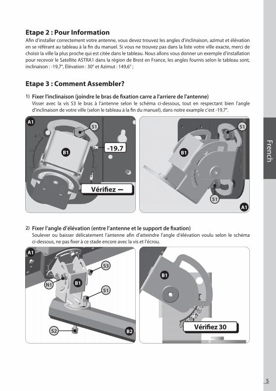
5
French
Etape 2 : Pour InformationAfin d’installer correctement votre antenne, vous devez trouvez les angles d’inclinaison, azimut et élévation en se référant au tableau à la fin du manuel. Si vous ne trouvez pas dans la liste votre ville exacte, merci de choisir la ville la plus proche qui est citée dans le tableau. Nous allons vous donner un exemple d’installation pour recevoir le Satellite ASTRA1 dans la région de Brest en France, les angles fournis selon le tableau sont, inclinaison : -19,7°, Elévation : 30° et Azimut : 149,6° ;
Etape 3 : Comment Assembler?
S1 S1
S1
-19.7
Vérifiez
A1
A1
B1 B1
S3
S1
S2
N1
Vérifiez 30
A1
B1
B2
B1
Fixer l'inclinaison (joindre le bras de fixation carre a l'arriere de l'antenne) Visser avec la vis S3 le bras à l’antenne selon le schéma ci-dessous, tout en respectant bien l’angle d’inclinaison de votre ville (selon le tableau à la fin du manuel), dans notre example c’est -19,7°.
1)
Fixer l’angle d’élévation (entre l’antenne et le support de fixation) Soulever ou baisser délicatement l’antenne afin d’atteindre l’angle d’élévation voulu selon le schéma ci-dessous, ne pas fixer à ce stade encore avec la vis et l’écrou.
2)

6
Etape 4 : Connexion de l’Antenne au Récepteur SatelliteAprès avoir installé l’antenne dans un espace à ciel ouvert et l’avoir monté de la façon dont vous le souhaitiez, l’étape suivante consiste à connecter l’ensemble. Afin de pouvoir regarder vos programmes satellites préférés, vous devez connecter votre antenne satellite à un récepteur par un câble. Le câble reliant l’antenne au récepteur Satellite ne doit pas excéder 30m car cela diminuerait la qualité du signal.
L’utilisation d’un câble long ou de mauvaise qualité et de prise non isolée peut entraîner une perte du niveau de signal, il serait donc préférable d’utiliser un câble coaxial RG6 (câble HF 17 VATG ou 19 VATG) afin de minimiser la perte de signal.
S4
N1
S4
B3
B3B4
B4
Utilisez des écrous à griffes.Ceci n’est pas inclus avec.
Mur
Mur
B2B2
Installation du Bras de Fixation ASelon l’emplacement de l’antenne et le type d’installation vous devez posez le bras de fixation A(B3 sur la figure) soit en type rambarde de balcon ou en accroche murale. Soyez sûr que vous êtes dans le bonne direction vers le satellite et qu’il n’y ait aucun obstacle. Afin de supporter le poids de l’antenne il va falloir bien visser les écrous (N1). Pour l’accroche murale des vis spéciaux seront nécessaires selon votre type de mur, merci de les acheter séparément.
3)
L’arrière bras et les Bras de fixation A(B3)Monter l’ensemble selon le schéma ci-joint, afin de pouvoir tenir correctement l’antenne, il va falloir bien visser les écrous (N1) selon le shcéma.
4)
N1
N1
S3S3

7
French
A) Comment préparer le câble ?
Il est essentiel que le câble coaxial ne soit pas endommagé ou tordu durant la procédure d’installation.
B) Comment connecter le câble à l’Antenne et au Récepteur Satellite ?
Un côté relié àI’antenne
L’antre côté reliéau récepteur
Câble
15mm Cache de protection connecteur
Conecteur femelle
8mm
3mm
Menu Pointage Antenne
Signal: 0
Satelite : ASTRA 1Répéteur : 23Convertisseur de Fréquences : ON Frequenz : 12640
Etape 5 : Menu Pointage de l’AntenneLorsque tout est connecté, allumez la TV et le récepteur Satellite. Sélectionnez le Menu Pointage de l’Antenne sur votre décodeur. Cette image montre le niveau de signal et l’écran qui apparaîtra sur votre TV.N’oubliez pas de mettre le Convertisseur de Fréquence Descendant sur ON. Vous aurez besoin que quelqu’un reste devant la TV pour vous indiquer quand le signal sera « bon » tandis que vous serez à l’extérieur pour essayer de régler l’antenne le mieux possible.
Le niveau et la qualité du signal sont indiqués sur l’écran de TV ; ils fluctueront et changeront de couleur en fonction du réglage et du mouvement de l’antenne pendant que vous serez en train de pointer et de constater (azimut, angle d’élévation et angle de déflexion). Le niveau indique la puissance du signal et la couleur correspond à la qualité de réception du signal émanant du satellite choisi.

8
Assurez-vous que toutes les connections de câble sont correctes et que chaque connection est correctement placée et resserée.Vérifiez que l’interieur de chaque connecteur de câble est propre.Vérifiez l’Angle d’Azimut, d’Elévation et d’Inclinaision correspondant à votre situation géographique par le biais du code de zone.Assurez-vous que le réglage d’Inclinaison n’est pas différent de celui recommandé en fonction de l’endroit où est fixée l’antenne.Assurez-vous que le réglage d’Inclinaison n’est pas différent de celui recommandé en fonction de l’endroit où est fixée l’antenne.Un câble RG6 doté d’un solide conducteur en central en cuivre est fortement recommendé car il entraine une chute de tension continue plus faible que le câble RG6 cuivré, à conducteur central en acier.Un câble standard RG59 etraine trop de tesion continue et de baisse de signal, il ne peut être utilisé pour faire passer le signal satellite. Utilisez un câble coaxial RG6.Nous n’encourageous pas l’utilisation de composants complémentaires immédiatement disponibles sur certains marchés. Ils pourraient ne pas fonctionner ou entraîner des chutes supplémentaires detension continue et l’atténuation de l’amplitude du signal.Otez de tels composants et revenez aux connexions de base stipulées dans ce manuel puis revérifiez.Otez les composants spécifiques à la TV existants, tel que le répartiteur TV, etc ; réduisez l’installation au connexions de base stipulées dans ce guide. De tels composants ne fonctionneront pas avec le signal satellite et ils peuvent se trouver dans le mur où vous ne pouvezles voir. Dans le doute, branchez directement le câble RG6 à votre récepteur.Assurez-vous qu’il n’y ait pas d’obstacle(arbres, bâtiments, fenêtres, coins ou avancées du toit, votre corps ou vos mains)-le signal ne passe pas à travers les feuilles, les branches, le verre, etc.Assurez-vous que le câble du satellite est connecté à la “prise d’entrée” du satellite et non à la “prise d’entrée” de l’Antenne. La prise d’entrée de l’Antenne à l’arriére du récepteur sert à l’entrée de l’antenne hors émission ou à l’entrée du câble TV.Si tout a été effectué correctement et qu’aucun signal n’est capté, changez légèrement le réglage de l’angle d’élévation de l’antenne(+ /- 2 。, puis + /- 4 。par rapport aux réglage exigés) et recommencez la procédure.
•
••
•
•
•
•
•
••
•
•
•
Liste de dépannage pour Installation Initiale
Le signal du satellite peut être emporairement perdu cause d’inhabituelles chutes de pluie. Une antenne alignée de façon optimale et un câble le plus court possible minimise le risque d’“Evanouissement dû à la pluie”.Assurez-vous que l’antenne est montée solidement afin d’éviter qu’elle ne soit soufflée et sortie de son alignement par un vent fort.L’accumulation de neige sur l’antenne peut réduire la puissance du signal du satellite ; la neige doit être balayée dès que possible.La croissance du feuillage dans la ligne de visée de l’antenne vers le satellite peut entrîner une perte progessive d’image.
•
•
•
•
Perte de Signal / « Affaiblissement dû à la pluie »
Si aucun signal n’est perçu, assurez-vous que les manuels d’utilisation du récepteur
et de l’antenne ont été suivis à la lettre. Vérifiez ce qui suit :

Italian
Sommario
Che cosa è HUMAX Advanced-H40D?. . . . . . . . . . . . . . . . . . . . . . . . . . . . . . . . . . . . . . . . . . . . . . . . . . . . . . . . . . . . . . . . . . . . . . .Che cosa è HUMAX Advanced-H40D? 2|
Sicurezza. . . . . . . . . . . . . . . . . . . . . . . . . . . . . . . . . . . . . . . . . . . . . . . . . . . . . . . . . . . . . . . . . . . . . . . . . . . . . . . . . . . . . . . . . . . . . . . . . . . . .Sicurezza 2|
CONTENUTO DELLA CONFEZIONE. . . . . . . . . . . . . . . . . . . . . . . . . . . . . . . . . . . . . . . . . . . . . . . . . . . . . . . . . . . . . . . . . . . . . . . . . .CONTENUTO DELLA CONFEZIONE 3|
Installarla. . . . . . . . . . . . . . . . . . . . . . . . . . . . . . . . . . . . . . . . . . . . . . . . . . . . . . . . . . . . . . . . . . . . . . . . . . . . . . . . . . . . . . . . . . . . .
. . . . . . . . . . . . . . . . . . . . . . . . . . . . . . . . . . . . . . . . . . . . . . . . . . . . . . . . . . . . . . . . . . . . . . . . . . . . . . . . . . . . . .
. . . . . . . . . . . . . . . . . . . . . . . . . . . . . . . . . . . . . . . . . . . . . . . . . . . . . . . . . . . . . . . . . . . . . . . . . . . . . .
. . . . . . . . . . . . . . . . . . . . . . . . . . . . . . . . . . . . . . . . . . . . . . . . . . . . . . .
. . . . . . . . . . . . . . . . . . . . . . . . . . . . . . . . . . . . . . . . . . . . . . . . . . . . . .
. . . . . . . . . . . . . . . . . . . . . . . . . . . . . . . . . . . . . . . . . . . . . . . . . . . . . . . . . . . .
. . . . . . . . . . . . . . . . . . . . . . . . . . . . . . . . . . . . . . . . . . . . . .
. . . . . . . . . . . . . . . . . . . . . . . . . . .
. . . . . . . . . . . . . . . . . . . . . . . . . . . . . . . . . . . . . . . . . . . . . . . . . . . . . . . . . . . . . . . . . . . . . . . . .
. . . . . . . . . . . . . . . . . . . . . . . . . . . . . . . . . . . . . . . . . . . . . . . . . . . . . . . . . . . . .
. . . . . . . . . . . . . . . . . . . . . . . . . . . . . . . . . . . . . . . . . . . . . . . . . . . . . . . . . . . . . . . . . . . . . . . . . . . . . . .
. . . . . . . . . . . . . . . . . . . . . . . . . . . . . . . . . . . . . . . . . . . . . . . . .
Come installarla?
Fase 1: Dove installarla?
Fase 2: Scelta dell’installazione
Fase 3: Collegamento dell’antenna e del Set top box
Fase 4: Collegamento dell’antenna e del Set top box
Fase 5: Regolazione fine e fissaggio finale staffe
|
|
|
|
|
|
1) Regolare lo Skew (staffa B1 sul corpo dell 'antenna A1)2) Regolare l’Elevazione (unire il corpo antenna con il supporto principale)3) Installazione di una staffa fissa4) Fissaggio corpo antenna alla staffa A(B3)
A) Come preparare il cavo?B) Come collegare il cavo all’antenna e al set top box ?
4
4
5
5
6
7
5566
77
Individuazione ed eliminazione di problemi alla prima installazione. . . . . . . . . . . . . . . . . . . . . . . . . . . . . . . . . . . . . .Individuazione ed eliminazione di problemi alla prima installazione 8|
Perdita di segnale / attenuazione da pioggia. . . . . . . . . . . . . . . . . . . . . . . . . . . . . . . . . . . . . . . . . . . . . . . . . . . . . . . . . . . . . . .Perdita di segnale / attenuazione da pioggia 8|

2
H40D2 H40D4
ATTENZIONELe antenne non correttamente installate o installate in una struttura inadeguata sono facilmente danneg-giabili dal vento. Tali danni possono essere molto seri o addirittura mortali. Il proprietario e l’installatore sono pienamente responsabili del fatto che l’installazione sia strutturalmente adeguata per sopportare tutti i carichi (peso, vento e gelo) e adeguatamente sigillata contro dispersioni. Il costruttore non si riterrà responsabile per qualsiasi tipo di danno causato dal sistema satellitare dovuto alle molteplici e variabili applicazioni.
Prima di utilizzare questo prodotto, leggere attentamente il presente manuale e seguire esattamente le istruzioni di installazione, montaggio e orientamento.Vi preghiamo di seguire le seguenti istruzioni per evitare ogni problema tecnico.Qualsiasi campo magnetico vicino al HUMAX Advanced-H40D può causare una cattiva ricezione del segnale o addirittura comprometterla del tutto.Non perforare l’involucro di plastica dell’antenna, che la sigilla contro l’umidità.Maneggiare l’antenna con cura: qualsiasi urto può danneggiarne i componenti elettronici.Non togliere l’involucro: qualsiasi tentativo di riparazione da parte di personale non qualificato può essere pericoloso e annullare la garanzia.Ostacoli come costruzioni, alberi ecc. possono bloccare la ricezione del segnale dal satellite.Non dipingere o aggiungere altre sostanze sull’antenna, poiché possono impedire la ricezione del segnale dal satellite.Il cavo tra l’antenna e il ricevitore satellitare non deve superare i 30 m, pena la diminuzione della qualità el segnale.L’utilizzo di un jack non isolato può determinare perdita del segnale.Una volta effettuata la regolazione, stringere bene tutte le viti dell’antenna.Questo prodotto contiene un solo LNB universale ed è formalmente vietato aggiungere, cambiare o modificare l’LNB.Per maggiori dettagli sui punti precedenti o per qualsiasi altra informazione contattare il rivenditore o direttamente il servizio clienti.
•
••
•••
•••••••
Sicurezza
Che cosa è HUMAX Advanced-H40D?HUMAX Advanced-H40D è un’antenna satellitare piatta con doppia polarizzazione lineare; riceve il segnale dai maggiori satelliti e sostituisce il disco della vecchia parabola. Piccola, discreta e facile da usare, si installa in pochi minuti e si può utilizzare come antenna portatile per le ricezioni satellitari. HUMAX Advanced-H40D è utilizzabile per la ricezione di trasmis-sioni in chiaro e criptate (che richiedono un abbonamento con l’operatore); riceve inoltre i canali HD. Per l’utilizzo e l’installazione, leggere e seguire attentamente le istruzioni del manuale.
Usate piu di due televisioni a casa?
Guardare 2 canali e' possibile attraverso HUMAX advanced-H40D2Guardare anche 4 canali e' possibile attraverso HUMAX advanced-H40D4

3
Italian
N.
1
2
3
4
5
6
7
8
9
10
11
12
1
1
1
1
2
1
1
3
1
3
4
7
A1
B1
B2
B3
B4
B5
C1
S1
S2
S3
S4
N1
Antenna
Staffa angolare
Supporto principale
Staffa fissaggio A
Staffa fissaggio B
Chiave
Bussola
Vite M6x18 SEMS2
Vite M6x50 SEMS2
Dado testa quadra M6x50
Dado testa quadra M6x75
Dado M6
Simbolo Nome parte Immagine Quantità
CONTENUTO DELLA CONFEZIONE

4
Notafar riferimento alla tavola degli angoli di Azimut nell’ultima pagina del presente manuale.
Nota
< Bussola> < Angolo di Azimut >
per garantire un’accurata lettura della bussola, la preghiamo di tenersi lontani da grandi oggetti di metallo, nello specifico cavi elettrici, ed effettuare letture a più riprese.
Cattiva qualità del segnale
NO!NO!
Buona qualità del segnale
Si!Si!
Angolo di Azimut
S 180o
N 0o
Posizione satellite
InstallarlaSeguendo passo a passo le istruzioni è possibile installare con facilità HUMAX Advanced-H40D da soli o con l’aiuto di un antennista professionista.
Fase 1: Dove installarla?Per ricevere il segnale dal satellite, HUMAX Advanced-H40D va installata in uno spazio aperto (fuori casa/appartamento) nella direzione del satellite, verso l’equatore (il sud). Sarà necessaria la bussola per orientare esattamente HUMAX Advanced-H40D nella giusta direzione.
Verificare che non vi siano ostacoli davanti a HUMAX Advanced-H40D che possano diminuire la qualità della ricezione del segnale quali: costruzioni, alberi o altro (ricordarsi che gli alberi normalmente crescono e possono bloccare il segnale).
Per poter fissare e installare facilmente l’antenna si deve scegliere un’ubicazione accessibile e priva di potenziali pericoli per l’installazione.
È necessario valutare a come far passare il cavo in modo discreto da HUMAX Advanced-H40D fino al Set top Box (decodificatore). L’antenna non va messa troppo distante dal ricevitore satellitare; un cavo lungo più di 30 m. diminuisce la qualità del segnale.
Prima di installare l’antenna verificare che la scatola di HUMAX Advanced-H40D contenga tutti gli elementi citati nel “Contenuto della confezione”. Nell’eventualità di parti mancanti, contattare il rivenditore.
5
Italian
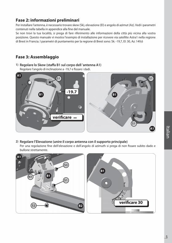
Fase 2: informazioni preliminariPer installare l'antenna, è necessario trovare skew (Sk), elevazione (El) e angolo di azimut (Az). Vedi i parametri contenuti nella tabella in appendice alla fine del manuale.Se non trovi la tua località, si prega di fare riferimento alle informazioni della città più vicina alla vostra posizione. Questo manuale vi mostra l'esempio di installazione per ricevere via satellite Astra1 nella regione di Brest in Francia. I parametri di puntamento per la regione di Brest sono: Sk: -19,7, El: 30, Az: 149,6
Fase 3: Assemblaggio
S1 S1
S1
-19.7
verificare
A1
A1
B1 B1
S3
S1
S2
N1
verificare 30
A1
B1
B2
B1
Regolare lo Skew (staffa B1 sul corpo dell 'antenna A1)Regolare l’angolo di inclinazione a -19,7 e fissare i dadi.
1)
Regolare l’Elevazione (unire il corpo antenna con il supporto principale)Per una regolazione fine dell’elevazione e dell’angolo di azimuth si prega di non fissare subito dado e bullone strettamente.
2)

6
Fase 4: Collegamento dell’antenna e del Set top boxDopo aver installato l’antenna in uno spazio aperto e averla montata nella maniera prescelta, procedere ad effettuare tutti i collegamenti.. Per poter vedere i propri programmi preferiti, collegare l’antenna satellitare al ricevitore tramite cavo. Il cavo tra l’antenna e il ricevitore satellitare non deve superare i 30m, pena la diminuzione della qualità del segnale.
Un cavo troppo lungo o di cattiva qualità e jack non isolati possono comportare una perdita del livello del segnale; è preferibile utilizzare un cavo coassiale RG6 (cavo HF 17VATC o 19VATC) per ridurre al minimo la perdita di segnale..
S4
N1
S4
B3
B3B4
B4
tasselli di fissaggionon inclusi
Muro
Muro
B2B2
Installazione di una staffa fissa È necessario installare la staffa di ancoraggio A(B3 nella figura) in base al tipo di installazione (montaggio su palo o balcone, montaggio a parete). Assicurarsi che la direzione sia verso il satellite. Al fine di sostenere l'antenna, il dado (N1), dovrebbe essere stretto quanto possibile.Per l'installazione a muro effettuare il fissaggio con appositi tasselli (non forniti)
3)
Fissaggio corpo antenna alla staffa A(B3)Fissare la staffa principale dell'antenna B2 alla staffa B3.Stringere i dadi (N1) quanto possibile.
4)
N1
N1
S3

7
Italian
A) Come preparare il cavo?
È importante che il cavo coassiale non venga danneggiato o piegato durante le procedure di installazione.
B) Come collegare il cavo all’antenna e al set top box ?
Lato antenna
Lato ricevitore
Cavo
15mm RIVESTIMENTO CONNETTORE
CONNETTORE F
8mm
3mm
Menù Puntamento antenna
Signal: 0
Satelite : ASTRA 1Transponder: 23LNB: ONFrequenza: 12640
Fase 5: Regolazione fine e fissaggio finale staffeUna volta completata la messa a punto per la ricezione del segnale, si prega di avvitare bulloni e dadi.
E' possibile verificare il livello e la qualità del segnale tramite il decoder direttamente sullo schermo del televisore. Il livello indica la potenza del segnale e il colore indica la qualità di ricezione del segnale del satellite scelto. Durante la fase di regolazione dell'antenna (azimuth, elevazione) tali livelli variano in base ai movimenti dell'antenna.
8
Verificare che tutte le connessioni dei cavi siano corrette e che ogni connessione sia correttamente alloggiata/fissata.Ispezionare l’interno di ogni connettore di cavo per spolverarlo o cotrollare che non vi siano possibili corti circuiti tra l’interno del connettore e la copertura.Verificare angoli di Azimut, Elevazione e Inclinazione in base al proprio CAP.Verificare che i puntatori di Inclinazione e Elevazione siano correttamente allineati alle scale. Non utilizzare rondelle o dadi come riferimento.Verificare che la regolazione di Inclinazione non sia cambiata rispetto all’impostazione raccomandata per la posizione dell’antenna.Il cavo RG6 con conduttore centrale solido in rame è caldamente raccomandato perché ha una più bassa caduta di tensione DC rispetto ai cavi RG 6 con conduttore in acciaio rivestito in rame.Il cavo RG 59 standard causa eccessiva caduta di tensione DC e perdita di segnale; non può essere utilizzato per il segnale satellitare. Va utilizzato un cavo coassiale RG 6.Alcuni componenti di ricambio e accessori esistenti in commercio potrebbero avere caratteristiche diverse da quelle pubblicizzate. Potrebbero non funzionare o causare ulteriori cadute di tensione e attenuazioni dell’ampiezza del segnale.Eliminare tali componenti, limitarsi alle connessioni base specificate nel manuale e riverificare.Rimuovere i componenti specifici preesistenti della TV, come splitter ecc.Lasciare solo i collegamenti base descritti in questa guida. Tali componenti possono non funzionare con il segnale satellitare e possono essere invisibili poiché a muro. In caso di dubbio, far passare il cavo RG 6 direttamente al ricevitore.Verificare l’assenza di ostacoli (alberi, costruzioni, finestre, angoli o sporgenze del tetto, il proprio corpo o mani) – il segnale non oltrepassa fogliame, rami, vetro ecc.Verificare che il cavo satellitare sia connesso alla presa “Sat-In” e non alla presa “Antenna-In”. La presa “Antenna In”sul retro del ricevitore è per l’ingresso antenna terrestre o TV via cavo.Se tutto è stato eseguito correttamente, ma il segnale è ancora assente, cambiare leggermente la regolazione di elevazione dell’antenna (± 2°, poi ± 4° rispetto a quanto richiesto per l’impostazione) e ripetere la procedura.Verificare che la scheda di accesso del ricevitore sia completamente inserita nell’apposito slot e correttamente orientata.
•
•
••
•
•
•
•
•••
•
•
•
•
Il segnale satellitare può essere temporaneamente assente a causa di pioggia particolarmente violenta. Un ottimale allineamento dell’antenna, associato a un cavo il più corto possibile, minimizza l’attenuazione da pioggia.Verificare che l’antenna sia montata stabilmente per evitare che possa perdere l’allineamento in caso di vento forte.Un’importante caduta di neve che si accumula sull’antenna può ridurre la potenza del segnale; va eliminata al più presto.La crescita di fogliame sulla linea di veduta dell’antenna può generare una graduale perdita dell’immagine.
•
••
•
Perdita di segnale / attenuazione da pioggia
Se il segnale non viene trovato e i manuali utente antenna e utente ricevitore sono stati seguiti adeguatamente, effettuare i seguenti controlli :
Individuazione ed eliminazione di problemi alla prima installazione


