bearings and spacers rg36 a2 - reliance precision limited · 3 10 mm bore 123 bronze bearings...
TRANSCRIPT

Bearings and Spacers


Bea
rings
and
Spa
cers
12
Section Contents
Ball Bearings P4 ......................................................................Page 122
Bronze Bearings ........................................................................Page 123
Moulded Bearings......................................................................Page 124
Bearing Preload Washers ........................................................Page 125
Bearing Spacers ........................................................................Page 126
Technical Information................................................................Page T121

122 Contact us for product information, design support and custom [email protected] +44 (0) 1484 601002 www.reliance.co.uk
Bearings andSpacers
Associated ProductsShafts: page 112
Bearing preload washers: page 125Bearing spacers: page 126
Part number selection tablePlain Flanged
Part Number Dimensions Specification
Plain FlangedBoreDiaØB
O/DØD
Max Min
Width
W
Radii
R(min)
FlangeDiaØA
Max Min
FlangeWidth
EMax Min
Load RatingsN
DynamicC
StaticCo
B1102SP4B1103SP4B1104SP4B1105SP4B1106SP4B1108SP4B1110SP4
B2102SP4B2103SP4B2104SP4B2105SP4B2106SP4B2108SP4B2110SP4
234568
10
57911131619
4.9966.9968.99610.99612.99615.99618.995
2.33.04.05.05.06.07.0
0.080.100.100.150.150.200.30
6.158.15
10.3512.5515.0518.0521.05
6.058.05
10.2512.4514.9517.9520.95
0.60.81.01.01.11.31.5
0.560.760.960.921.021.221.38
192432658734
109617951922
59149226282437776915
Features and options• Operating temperature range: 73ºC to +121ºC• Lubricant: grease to MILG21164 and MILG23827• Double shielded• Imperial sizes available
Technical support• Spur gear and bearing load calculation see page T121• Bearing force sharing see page T123• Bearing installation and housing considerations see page T124
P4 Ball Bearings
All dimensions in mmGenerally in accordance with ISO 492,tolerance class 4Material: X65Cr13 stainless steel

3 10 mm Bore
123
Bronze Bearings
Contact us for product information, design support and custom [email protected] +44 (0) 1484 601002 www.reliance.co.uk
Bea
rings
and
Spac
ers
All dimensions in mmGeneral tolerances ±0.13 mmMaterial: Bronze ASTM B 438
Type 2, Grade 1
Associated ProductsShafts: page 112
Part number selection tablePart Number Bore
ØB1O/DØD
LengthL
Flange DiaØA
Flange WidthEPlain Flanged
BBM13BBM14BBM15BBM16BBM18BBM110
BBM23BBM24BBM25BBM26BBM28BBM210
34568
10
688
101213
61212121216
912141616
1.52.0
2.02.01.5
1 Bearing bore tolerances after assembly are: plain bearings H7, flanged bearings H8.Recommended housing bore H7
Plain Flanged
Features and options• Operating temperature range: 20ºC to +100ºC• Oil impregnated• Max speed 30,000 rpm• p.v (@0.5 m/s) = 1.75 N/mm2.m/s• pmax =13.8 N/mm• vmax = 6.1 m/s (rotational)• Imperial sizes available

2 12 mm Bore
124
Moulded Bearings
Contact us for product information, design support and custom [email protected] +44 (0) 1484 601002 www.reliance.co.uk
Bearings andSpacers
Associated ProductsShafts: page 112
Leadscrews: page 71Bearing spacers: page 126
All dimensions in mmGeneral tolerances ±0.13 mmMaterial: Self lubricating mouldedthermoplastic
Part Number BoreØB #
O/DØD
LengthL
Flange DiaØA
Flange WidthEPlain Flanged
BM82 2.0542.014 3.5 3.00
2.86
BM83 BM93 3.0543.014 4.5 3.00
2.867.467.24 0.75
BM84 BM94 4.0684.020 5.5 4.00
3.829.469.24 0.75
BM85 5.0405.010 7.0 5.00
4.82
BM95 5.0685.020 7.0 5.00
4.8210.9510.68 1.00
BM86 BM96 6.0686.020 8.0 6.00
5.8211.9511.68 1.00
BM88 8.0838.025 10.0 8.00
7.78
BM98 8.0838.025 10.0 9.50
9.2814.9514.68 1.00
BM810 BM910 10.08310.025 12.0 10.00
9.7817.9517.68 1.00
BM812 BM912 12.10212.032 14.0 12.00
11.7319.9319.61 1.00
Part number selection table
# Tolerance for ØB is after press fitting into a housing bore of tolerance H7
Plain Flanged
Features and options• Operating temperature tange: 40ºC to +130ºC• (p.v)max = 1.0 N/mm2.m/s• pmax = 80 N/mm2
• vmax = 1.0 m/s (rotational) or 4.0 m/s (linear)• Imperial sizes available
4.5 15 mm Bore
125
Bearing Preload Washers
Contact us for product information, design support and custom [email protected] +44 (0) 1484 601002 www.reliance.co.uk
Bea
rings
and
Spac
ers
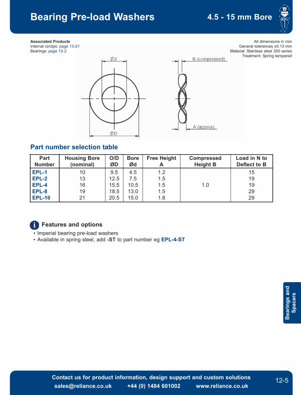
All dimensions in mmGeneral tolerances ±0.13 mm
Material: Stainless steel 300 seriesTreatment: Spring tempered
Associated ProductsInternal circlips: page 1321Bearings: page 122
PartNumber
Housing Bore(nominal)
O/DØD
BoreØd
Free HeightA
CompressedHeight B
Load in N toDeflect to B
EPL1EPL2EPL4EPL8EPL10
1013161921
9.512.515.518.520.5
4.57.510.513.015.0
1.21.51.51.51.8
1.0
1519192929
Part number selection table
Features and options• Imperial bearing preload washers• Available in spring steel, add ST to part number eg EPL4ST

Inner Race
126
Bearing Spacers
Contact us for product information, design support and custom [email protected] +44 (0) 1484 601002 www.reliance.co.uk
Bearings andSpacers
Associated ProductsShafts: page 112
Leadscrews: page 71Bearings: page 122
All dimensions in mmGeneral tolerances ±0.13 mmMaterial: Stainless steel 300 series
ShaftNominal
Spacer BoreØd
Spacer O/DØD
234568
10
234568
10
3.04.15.36.77.9
10.212.3
NominalShaft Dia
Ød
Thickness B± 0.025
0.05 0.10 0.15 0.20 0.25 0.30 0.40 0.50234568
10
SS1117SS1125SS1133SS1137SS1145SS1149SS1153
SS1118SS1126SS1101SS1138SS1105SS1109SS1113
SS1119SS1127SS1102SS1139SS1106SS1110SS1114
SS1120SS1128SS1134SS1140SS1146SS1150SS1154
SS1121SS1129SS1103SS1141SS1107SS1111SS1115
SS1122SS1130SS1135SS1142SS1147SS1151SS1155
SS1123SS1131SS1104SS1143SS1108SS1112SS1116
SS1124SS1132SS1136SS1144SS1148SS1152SS1156
Dimensions
Part number selection table
Product options• Imperial sizes available
Outer Race
127
Bearing Spacers
Contact us for product information, design support and custom [email protected] +44 (0) 1484 601002 www.reliance.co.uk
Bea
rings
and
Spac
ers
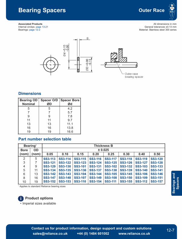
All dimensions in mmGeneral tolerances ±0.13 mm
Material: Stainless steel 300 series
Associated ProductsInternal circlips: page 1321Bearings: page 122
Bearing ODNominal
Spacer O/DØD
Spacer BoreØd
57911131619
57911131619
4.25.77.89.711.113.816.6
Bearing1 Thickness BBore(nom)
OD(nom)
± 0.0250.05 0.10 0.15 0.20 0.25 0.30 0.40 0.50
234568
10
57911131619
SS3113SS3121SS3129SS3134SS3142SS3147SS3152
SS3114SS3122SS3130SS3135SS3143SS3148SS3153
SS3115SS3123SS3101SS3136SS3104SS3107SS3110
SS3116SS3124SS3131SS3137SS3144SS3149SS3154
SS3117SS3125SS3102SS3138SS3105SS3108SS3111
SS3118SS3126SS3132SS3139SS3145SS3150SS3155
SS3119SS3127SS3103SS3140SS3106SS3109SS3112
SS3120SS3128SS3133SS3141SS3146SS3151SS3157
Dimensions
Part number selection table
Product options• Imperial sizes available
1 Applies to standard Reliance bearing sizes

TechnicalInformation
T121
Bearings and Spacers
Contact us for product information, design support and custom [email protected] +44 (0) 1484 601002 www.reliance.co.uk
Tech
nica
lIn
form
atio
n
SPECIFICATION
The first step in choosing the correct bearing for an application is to determine the forces which it willsupport in service. The forces will depend on the exact configuration of the system and will probablyinclude some, or all, of the following:
• The weight of the shaft, including gears and other shaft attachments.• Gear mesh reaction forces, due to torque transmission (see below).• Gear separation due to antibacklash forces.• Forces due to belt or pulley tensions.• Axial preload forces.
GEAR MESH REACTIONS
In order to calculate the loads which will be applied to the bearings in the simply supported spur gearpass arrangement shown on the next page, it is first necessary to calculate the forces at the gearmesh.
The tangential force at the gear mesh can be calculated from the following equation:
where T = Torqueand r = Radius
and the separating force at the gear mesh can be calculated from:
Wr' = Wt tanφt where φt = transverse pressure angle= normal pressure angle for spur gears= 20º for our standard gears
(for 20º pressure angle spur gear)
If required, the total radial load at the gear mesh can be calculated from the final equation:
Bearing loads
PositionForces At These Positions
Tangential Force Separating Force Total Radial Load
Gear Mesh
Bearing A
Bearing B
Bearing C
Bearing D
Wt = T/r
Wr' = 0.364Wt
Wr = (Wt)2 + (Wr')2

TechnicalInformation Bearings and Spacers
T122 Contact us for product information, design support and custom [email protected] +44 (0) 1484 601002 www.reliance.co.uk
TechnicalInform
ation
Bearing loads and gear mesh forces diagram
For bearing life calculations based on these radial loads see page T123.
Note These equations can only be used for spur gear calculations, because they are not affected byselfgenerated axial forces.
TechnicalInformation
T123
Bearings and Spacers
Contact us for product information, design support and custom [email protected] +44 (0) 1484 601002 www.reliance.co.uk
Tech
nica
lIn
form
atio
n
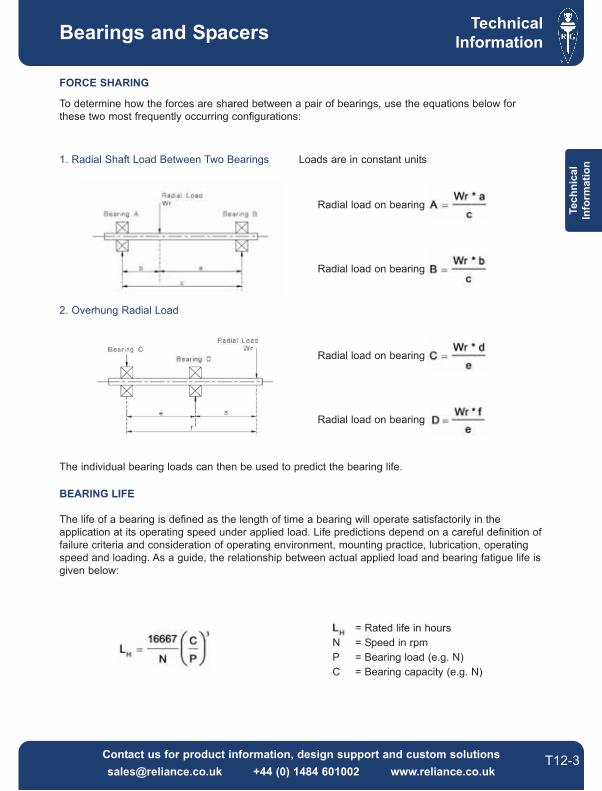
Radial load on bearing
Radial load on bearing
1. Radial Shaft Load Between Two Bearings Loads are in constant units
FORCE SHARING
To determine how the forces are shared between a pair of bearings, use the equations below forthese two most frequently occurring configurations:
2. Overhung Radial Load
Radial load on bearing
Radial load on bearing
The individual bearing loads can then be used to predict the bearing life.
BEARING LIFE
The life of a bearing is defined as the length of time a bearing will operate satisfactorily in theapplication at its operating speed under applied load. Life predictions depend on a careful definition offailure criteria and consideration of operating environment, mounting practice, lubrication, operatingspeed and loading. As a guide, the relationship between actual applied load and bearing fatigue life isgiven below:
= Rated life in hoursN = Speed in rpmP = Bearing load (e.g. N)C = Bearing capacity (e.g. N)

TechnicalInformation Bearings and Spacers
T124 Contact us for product information, design support and custom [email protected] +44 (0) 1484 601002 www.reliance.co.uk
TechnicalInform
ation
INSTALLATION AND HOUSING CONSIDERATIONS
The installation of a bearing will usually be determined by how it fits with its mating components.Interference or transition fits provide the most positive location of the bearing, however, they willrequire pressing during installation. Clearance fits allow the bearing to be assembled very easily, butcould potentially lead to problems depending on the operating conditions. If a press fit is required, it isessential that no appreciable force is transferred through the rolling elements of the bearing duringinstallation.
Special care must be taken when using bearings in aluminium housings, especially when widetemperature variations are expected. It is possible for the contraction of the housing to squash thebearing raceway and remove the radial clearance required for the bearing to operate.
Potential problems with clearance fits:Fretting Wearing away of the surface due to rubbing of the components.Accuracy Accuracy can be compromised due to unpredictable movement.
Potential problems with interference fits:Assembly Can be difficult or impossible without damaging the bearing.Radial clearance Can be reduced if the interference is too great.

RG36 Issue A2