beamnrc users manual
TRANSCRIPT

BEAMnrc Users Manual
D.W.O. Rogers, B. Walters, I. KawrakowIonizing Radiation Standards
National Research Council of CanadaOttawa, K1A OR6
drogers at physics.carleton.cabwalters at irs.phy.nrc.ca
iwan at irs.phy.nrc.caPrinted: May 18, 2011(last edited 2011/05/09 19:16:55 )
NRCC Report PIRS-0509(A)revL
BEAM simulation AECL Therac 20:
20 MeV electron radiotherapy beam
acceleratorvacuum exit
window
monitor ion chamber
adjustable jaws
patientplane
electron tracks bluephoton tracks yellow
beam applicator
Source tex file is: $OMEGA HOME/doc/pirs0509/pirs0509.texAvailable on-line via:
http://www.irs.inms.nrc.ca/inms/irs/BEAM/beamhome.html
c©NRC Canada, 2007

2 NRCC Report PIRS-0509(A)revL
BEAM Code System General Licence
The BEAM code system (i.e. all pieces of code saying they are subject to the BEAMGeneral License, including routines related to the 1999 and later versions of BEAM orBEAMnrc, DOSXYZ or DOSXYZnrc, BEAMDP, ctcreate and EGS Windows, as well asthe CMs (BEAM component modules), scripts, all the auxiliary routines except those fromthe EGS4 Monte Carlo system and all associated documentation) are copyrighted materialowned by the National Research Council of Canada, all rights reserved.
1) The NRC grants the user a non-transferable, non-exclusive licence to use this systemfree of charge only for non-commercial research or educational purposes. All proprietaryinterest, right, title and copyright in the BEAM code system remains with NRC.
2) The express, written consent of NRC is required if the BEAM code system or any partthereof is used by an individual or an organization for developing a commercial product orservice, or data generated by the code is used to develop commercial products or services.
3) The express, written consent of NRC is required if this code system or any part thereofis to be used in a fee for service application, either clinically or by consultants.
4) The code system must be obtained from NRC. Users may not copy nor distribute thecode system or parts thereof.
5) NRC disclaims any warranties, expressed, implied or statutory, of any kind or naturewith respect to the software, including without limitation any warranty of merchantabilityor fitness for a particular purpose. NRC shall not be liable in any event for any damages,whether direct or indirect, special or general, consequential or incidental, arising from theuse of the software.
6) This licence supersedes all prior communications, negotiations and agreements, writtenor oral, concerning the BEAM code system. No amendment or waiver of terms is effectiveunless in writing, signed by both parties and specifically states the intention to affect thislicence.
7) This licence is governed by the laws of Ontario and Canada applicable therein. Theuser consents to the jurisdiction of the federal court and the courts of Ontario.
—————- End of Licence ———————————-
Requests:Please report all bugs (and corrections if possible) to bwalters at irs.phy.nrc.ca ordrogers at physics.carleton.ca. Corrections will be patched into the code and explicitmention given in the documentation to the person providing a workable solution.
BEAMnrc Users Manual 3
Abstract
BEAMnrc is a Monte Carlo simulation system (Med. Phys. 22,1995,503 – 524) for modellingradiotherapy sources which was developed as part of the OMEGA project to develop 3-Dtreatment planning for radiotherapy (with the University of Wisconsin). BEAMnrc is builton the EGSnrc Code System[1]. Until 2004, BEAMnrc could only be run on Unix/Linux sys-tems. However, with the recent port of BEAMnrc to the EGSnrcMP system[2], BEAMnrccan also run on Windows-based systems. The purpose of this manual is to be a refer-ence/guide to someone using the BEAMnrc system.
This user’s manual covers general BEAMnrc inputs and component module (CM) ge-ometries and inputs. It discusses how to use the various variance reduction techniques whichare part of the system, most importantly, range rejection, bremsstrahlung splitting, photonforcing in a specific region and Russian Roulette. It also covers the structure of the direc-tory system used for the BEAMnrc system, the utility codes available (readphsp, addphsp,checkCM8 etc.), the installation procedure, the phase space file definition and it has crossreferences to all related BEAMnrc documentation. Appendix A gives a specification forwriting new component modules.
Contents
1 Overview of BEAMnrc 12
1.1 The Physics in BEAMnrc . . . . . . . . . . . . . . . . . . . . . . . . . . . . 12
1.2 Other documents available . . . . . . . . . . . . . . . . . . . . . . . . . . . . 13
1.3 Overview of the directory structure . . . . . . . . . . . . . . . . . . . . . . . 13
1.4 Overview of running BEAMnrc . . . . . . . . . . . . . . . . . . . . . . . . . 17
2 Building/compiling/running BEAMnrc 18
2.1 “Specifying” Accelerators . . . . . . . . . . . . . . . . . . . . . . . . . . . . . 19
2.2 Building an Accelerator: The beam build Code . . . . . . . . . . . . . . . . 19
2.3 Compiling an Accelerator using make . . . . . . . . . . . . . . . . . . . . . . 20
2.3.1 Compiling an Accelerator as a Shared Library . . . . . . . . . . . . . 21
Last edited 2011/05/09 19:16:55 CONTENTS
4 NRCC Report PIRS-0509(A)revL
2.4 Compiling an Accelerator using mf (Unix/Linux specific) . . . . . . . . . . . 22
2.5 Building/Compiling with the BEAM GUI . . . . . . . . . . . . . . . . . . . 22
2.6 Internal Documentation & Input Description . . . . . . . . . . . . . . . . . . 22
2.7 Running an Accelerator Simulation . . . . . . . . . . . . . . . . . . . . . . . 23
2.7.1 Batch Runs . . . . . . . . . . . . . . . . . . . . . . . . . . . . . . . . 24
2.8 Running BEAMnrc using the GUI . . . . . . . . . . . . . . . . . . . . . . . . 25
2.9 A Note on Temporary Working Directories . . . . . . . . . . . . . . . . . . . 25
2.10 BEAMnrc Output Files . . . . . . . . . . . . . . . . . . . . . . . . . . . . . . 25
2.11 Changing the defaults . . . . . . . . . . . . . . . . . . . . . . . . . . . . . . 28
2.12 Some Details . . . . . . . . . . . . . . . . . . . . . . . . . . . . . . . . . . . 29
2.12.1 The BEAM myaccel.io File . . . . . . . . . . . . . . . . . . . . . . . . 29
2.12.2 What’s in BEAM myaccel macros.mortran and BEAM myaccel cm.mortran 30
2.12.3 Files used during Compilation with make . . . . . . . . . . . . . . . . 31
2.12.4 Files Concatenated to Create mortjob.mortran . . . . . . . . . . . . 33
3 Description of main BEAMnrc input file 36
3.1 Sample input files . . . . . . . . . . . . . . . . . . . . . . . . . . . . . . . . . 62
4 Source Routines 63
4.1 ISOURC=0: Parallel Circular Beam . . . . . . . . . . . . . . . . . . . . . . . 64
4.2 ISOURC=1: Isotropic Point Source on Z-axis . . . . . . . . . . . . . . . . . 65
4.3 ISOURC=3: Interior Isotropic Cylindrical Source . . . . . . . . . . . . . . . 66
4.4 ISOURC=5: NRC Swept BEAM . . . . . . . . . . . . . . . . . . . . . . . . 67
4.5 ISOURC=6: Parallel Rectangular Beam . . . . . . . . . . . . . . . . . . . . 68
4.6 ISOURC=7: Scanning Sawtooth Beam . . . . . . . . . . . . . . . . . . . . . 69
4.7 ISOURC=8: Scanned Point Source for MM50–Uniform . . . . . . . . . . . . 70
4.8 ISOURC=9: Scanned Point Source for MM50–Discrete . . . . . . . . . . . . 71
4.9 ISOURC=10: Parallel Circular Beam Incident from Side . . . . . . . . . . . 72
4.10 ISOURC=13: Parallel Rectangular Beam Incident from Side . . . . . . . . . 73
4.11 ISOURC=15: NRC Swept Beam (Radial Variation, Divergence) . . . . . . . 74
4.12 ISOURC=19: Elliptical Beam with Gaussian Distributions in X and Y, Par-allel or with Angular Spread . . . . . . . . . . . . . . . . . . . . . . . . . . . 76
CONTENTS CONTENTS

BEAMnrc Users Manual 5
4.13 ISOURC=21: Phase Space Source . . . . . . . . . . . . . . . . . . . . . . . . 77
Value of NRCYCL . . . . . . . . . . . . . . . . . . . . . . . . . . . . . . 78
Inputs IPARALLEL and PARNUM . . . . . . . . . . . . . . . . . . . . . . 79
Inputs re DBS . . . . . . . . . . . . . . . . . . . . . . . . . . . . . . . 79
4.14 ISOURC=24: Phase Space Source Incident from User-specified Angle . . . . 80
4.15 ISOURC=23: BEAM Simulation Source Incident from User-specified Angle . 81
4.16 ISOURC=31: Phase Space Reconstructed Using BeamModels . . . . . . . . . . . . . . . . . . . . . . . . . . . . . . . . . . . . . . . 83
5 Monoenergetic vs Energy Spectrum Sources 84
6 Variance Reduction in BEAMnrc 85
6.1 Range Rejection . . . . . . . . . . . . . . . . . . . . . . . . . . . . . . . . . . 85
6.2 Photon Forcing . . . . . . . . . . . . . . . . . . . . . . . . . . . . . . . . . . 86
6.3 Brem Splitting and Russian Roulette . . . . . . . . . . . . . . . . . . . . . . 87
6.3.1 Uniform Bremsstrahlung Splitting . . . . . . . . . . . . . . . . . . . . 87
6.3.2 Selective Bremsstrahlung Splitting . . . . . . . . . . . . . . . . . . . 87
6.3.3 Charged Particle Russian Roulette . . . . . . . . . . . . . . . . . . . 88
6.3.4 Directional Bremsstrahlung Splitting (DBS) . . . . . . . . . . . . . . 89
DBS inputs . . . . . . . . . . . . . . . . . . . . . . . . . . . . . . . . 89
Outline of the DBS algorithm . . . . . . . . . . . . . . . . . . . . . . 91
DBS parameter selection . . . . . . . . . . . . . . . . . . . . . . . . . 92
Augmented range rejection with DBS . . . . . . . . . . . . . . . . . . 93
6.4 BCSE . . . . . . . . . . . . . . . . . . . . . . . . . . . . . . . . . . . . . . . 94
6.4.1 BCSE inputs . . . . . . . . . . . . . . . . . . . . . . . . . . . . . . . 94
6.4.2 Simulation optimization with BCSE . . . . . . . . . . . . . . . . . . . 95
6.4.3 Restrictions . . . . . . . . . . . . . . . . . . . . . . . . . . . . . . . . 96
6.4.4 Outline of the BCSE algorithm . . . . . . . . . . . . . . . . . . . . . 96
7 Phase Space Files 97
7.1 Description of Phase Space Files . . . . . . . . . . . . . . . . . . . . . . . . . 97
7.2 Directory for Phase Space Output . . . . . . . . . . . . . . . . . . . . . . . . 100
7.3 IAEA-format phase space data . . . . . . . . . . . . . . . . . . . . . . . . . . 101
Last edited 2011/05/09 19:16:55 CONTENTS

6 NRCC Report PIRS-0509(A)revL
7.3.1 IAEA format . . . . . . . . . . . . . . . . . . . . . . . . . . . . . . . 101
7.3.2 Writing IAEA phase space data . . . . . . . . . . . . . . . . . . . . . 103
7.3.3 Reading IAEA phase space data . . . . . . . . . . . . . . . . . . . . . 103
7.4 readphsp . . . . . . . . . . . . . . . . . . . . . . . . . . . . . . . . . . . . . . 103
7.5 BEAMDP . . . . . . . . . . . . . . . . . . . . . . . . . . . . . . . . . . . . . 104
8 Tracking a Particle’s History using LATCH 104
9 Calculating Dose Components 108
10 Other Input Variables 109
10.1 IWATCH . . . . . . . . . . . . . . . . . . . . . . . . . . . . . . . . . . . . . 109
10.2 ISTORE . . . . . . . . . . . . . . . . . . . . . . . . . . . . . . . . . . . . . . 110
10.3 IRESTART . . . . . . . . . . . . . . . . . . . . . . . . . . . . . . . . . . . . 110
10.4 IO OPT . . . . . . . . . . . . . . . . . . . . . . . . . . . . . . . . . . . . . . 111
10.5 IDAT . . . . . . . . . . . . . . . . . . . . . . . . . . . . . . . . . . . . . . . . 111
10.6 IZLAST . . . . . . . . . . . . . . . . . . . . . . . . . . . . . . . . . . . . . . 112
10.7 NCASE . . . . . . . . . . . . . . . . . . . . . . . . . . . . . . . . . . . . . . 112
10.8 IXXIN, JXXIN . . . . . . . . . . . . . . . . . . . . . . . . . . . . . . . . . . 112
10.9 TIMMAX . . . . . . . . . . . . . . . . . . . . . . . . . . . . . . . . . . . . . 113
10.10 ECUTIN . . . . . . . . . . . . . . . . . . . . . . . . . . . . . . . . . . . . . 113
10.11 PCUTIN . . . . . . . . . . . . . . . . . . . . . . . . . . . . . . . . . . . . . 114
10.12 ESTEPIN, SMAX, IDORAY, IFLUOR . . . . . . . . . . . . . . . . . . . . 114
10.13 ICM SPLIT, NSPLIT PHOT, NSPLIT ELEC . . . . . . . . . . . . . . . . . 115
11 EGSnrc inputs 115
11.1 Global ECUT (ECUT) . . . . . . . . . . . . . . . . . . . . . . . . . . . . . . . 116
11.2 Global PCUT (PCUT) . . . . . . . . . . . . . . . . . . . . . . . . . . . . . . . 116
11.3 Global SMAX (SMAXIR) . . . . . . . . . . . . . . . . . . . . . . . . . . . . . . 116
11.4 ESTEPE (ESTEPE) . . . . . . . . . . . . . . . . . . . . . . . . . . . . . . . . . 116
11.5 XImax (XIMAX) . . . . . . . . . . . . . . . . . . . . . . . . . . . . . . . . . . . 117
11.6 Boundary crossing algorithm (BCA) (bca algorithm) . . . . . . . . . . . 117
11.7 Skin depth for BCA (skindepth for bca) . . . . . . . . . . . . . . . . . . 117
CONTENTS CONTENTS

BEAMnrc Users Manual 7
11.8 Electron-step algorithm (transport algorithm) . . . . . . . . . . . . . 118
11.9 Spin effects (spin effects) . . . . . . . . . . . . . . . . . . . . . . . . . 118
11.10 Brems angular sampling (IBRDST) . . . . . . . . . . . . . . . . . . . . . . 118
11.11 Brems cross sections (IBR NIST) . . . . . . . . . . . . . . . . . . . . . . 118
11.12 Bound Compton scattering (IBCMP) . . . . . . . . . . . . . . . . . . . . . . 119
11.13 Compton cross sections (comp xsections) . . . . . . . . . . . . . . . . . 119
11.14Radiative Compton corrections (radc flag) . . . . . . . . . . . . . . . . 120
11.15 Pair angular sampling (IPRDST) . . . . . . . . . . . . . . . . . . . . . . . 120
11.16 Pair cross sections (pair nrc) . . . . . . . . . . . . . . . . . . . . . . . 120
11.17 Photoelectron angular sampling (IPHTER) . . . . . . . . . . . . . . . . . 120
11.18 Rayleigh scattering (IRAYLR) . . . . . . . . . . . . . . . . . . . . . . . . 121
11.19 Atomic Relaxations (IEDGFL) . . . . . . . . . . . . . . . . . . . . . . . . . 121
11.20 Electron impact ionization (eii flag) . . . . . . . . . . . . . . . . . . 122
11.21 Photon cross sections (photon xsections) . . . . . . . . . . . . . . . . 122
11.22Photon cross-sections output (xsec out) . . . . . . . . . . . . . . . . . 123
12 Custom user inputs 123
13 Parallel Processing 123
13.1 Random Number Seeds with Parallel Jobs . . . . . . . . . . . . . . . . . . . 125
13.2 Phase Space Sources with Parallel Jobs . . . . . . . . . . . . . . . . . . . . . 125
13.3 Combining Results from Parallel Jobs . . . . . . . . . . . . . . . . . . . . . . 125
13.4 Combining Phase Space Files from Parallel Runs using addphsp . . . . . . . 126
13.5 Parallel Jobs Run from the GUI . . . . . . . . . . . . . . . . . . . . . . . . . 127
13.6 Restarting Parallel Jobs . . . . . . . . . . . . . . . . . . . . . . . . . . . . . 127
14 Statistics in BEAMnrc 128
15 Component Modules 128
15.1 Introduction . . . . . . . . . . . . . . . . . . . . . . . . . . . . . . . . . . . . 128
15.2 What Each Component Module Does . . . . . . . . . . . . . . . . . . . . . . 128
15.3 Geometry and Input Parameters of Component Modules . . . . . . . . . . . 132
15.3.1 Overview . . . . . . . . . . . . . . . . . . . . . . . . . . . . . . . . . 132
Last edited 2011/05/09 19:16:55 CONTENTS

8 NRCC Report PIRS-0509(A)revL
15.3.2 SLABS . . . . . . . . . . . . . . . . . . . . . . . . . . . . . . . . . . . 133
15.3.3 CONS3R . . . . . . . . . . . . . . . . . . . . . . . . . . . . . . . . . 135
15.3.4 CONESTAK . . . . . . . . . . . . . . . . . . . . . . . . . . . . . . . 138
15.3.5 FLATFILT . . . . . . . . . . . . . . . . . . . . . . . . . . . . . . . . 141
15.3.6 CHAMBER . . . . . . . . . . . . . . . . . . . . . . . . . . . . . . . . 144
15.3.7 JAWS . . . . . . . . . . . . . . . . . . . . . . . . . . . . . . . . . . . 151
15.3.8 DYNJAWS . . . . . . . . . . . . . . . . . . . . . . . . . . . . . . . . 154
15.3.9 APPLICAT . . . . . . . . . . . . . . . . . . . . . . . . . . . . . . . . 158
15.3.10CIRCAPP . . . . . . . . . . . . . . . . . . . . . . . . . . . . . . . . . 162
15.3.11PYRAMIDS . . . . . . . . . . . . . . . . . . . . . . . . . . . . . . . . 164
15.3.12BLOCK . . . . . . . . . . . . . . . . . . . . . . . . . . . . . . . . . . 168
15.3.13MLC . . . . . . . . . . . . . . . . . . . . . . . . . . . . . . . . . . . . 172
15.3.14MLCQ . . . . . . . . . . . . . . . . . . . . . . . . . . . . . . . . . . . 176
15.3.15VARMLC . . . . . . . . . . . . . . . . . . . . . . . . . . . . . . . . . 180
15.3.16MLCE . . . . . . . . . . . . . . . . . . . . . . . . . . . . . . . . . . . 187
15.3.17DYNVMLC . . . . . . . . . . . . . . . . . . . . . . . . . . . . . . . . 193
15.3.18MESH . . . . . . . . . . . . . . . . . . . . . . . . . . . . . . . . . . . 205
15.3.19MIRROR . . . . . . . . . . . . . . . . . . . . . . . . . . . . . . . . . 208
15.3.20XTUBE . . . . . . . . . . . . . . . . . . . . . . . . . . . . . . . . . . 211
15.3.21SIDETUBE . . . . . . . . . . . . . . . . . . . . . . . . . . . . . . . . 215
15.3.22ARCCHM . . . . . . . . . . . . . . . . . . . . . . . . . . . . . . . . . 218
15.3.23SYNCJAWS . . . . . . . . . . . . . . . . . . . . . . . . . . . . . . . . 222
15.3.24SYNCVMLC . . . . . . . . . . . . . . . . . . . . . . . . . . . . . . . 222
15.3.25SYNCMLCE . . . . . . . . . . . . . . . . . . . . . . . . . . . . . . . 222
16 Cross-Section Data – PEGS4 223
16.1 Creating additional cross section data . . . . . . . . . . . . . . . . . . . . . . 223
16.2 Choice of AE,AP . . . . . . . . . . . . . . . . . . . . . . . . . . . . . . . . . 225
17 Distribution / Installation 226
17.1 Installing EGSnrcMP . . . . . . . . . . . . . . . . . . . . . . . . . . . . . . . 227
17.2 Installing OMEGA/BEAM . . . . . . . . . . . . . . . . . . . . . . . . . . . . 230
CONTENTS CONTENTS

BEAMnrc Users Manual 9
17.2.1 Using the Self-extracting Wizard . . . . . . . . . . . . . . . . . . . . 230
17.2.2 Using the Installation Wizard with Files Downloaded Separately . . . 232
17.2.3 Using the install beam Script (Unix/Linux only) . . . . . . . . . . . 233
17.2.4 A Note on Tcl/Tk . . . . . . . . . . . . . . . . . . . . . . . . . . . . 235
18 Known Problems/Restrictions 235
19 History of Revisions 236
19.1 Changes from BEAMnrc08 to BEAMnrc09 . . . . . . . . . . . . . . . . . . . . . 236
19.2 Changes from BEAMnrc07 to BEAMnrc08 . . . . . . . . . . . . . . . . . . . . . 237
19.3 Changes from BEAMnrc06 to BEAMnrc07 . . . . . . . . . . . . . . . . . . . . . 238
19.4 Changes from BEAMnrc05 to BEAMnrc06 . . . . . . . . . . . . . . . . . . . . . 238
19.5 Changes from BEAMnrc03 to BEAMnrc05 . . . . . . . . . . . . . . . . . . . . . 239
19.6 Changes from BEAMnrc02 to BEAMnrc03 . . . . . . . . . . . . . . . . . . . . . 240
19.7 Changes from BEAM00 to BEAMnrc02 . . . . . . . . . . . . . . . . . . . . . . . 240
20 Acknowledgements 242
21 References 243
Appendix A: Specifications for Component Modules for BEAMnrc 248
A.1 Overview . . . . . . . . . . . . . . . . . . . . . . . . . . . . . . . . . . . . . . 249
A.2 Writing Component Modules . . . . . . . . . . . . . . . . . . . . . . . . . . . 250
A.2.1 Tips . . . . . . . . . . . . . . . . . . . . . . . . . . . . . . . . . . . . 250
A.3 Specifications–CMNAME macros.mortran . . . . . . . . . . . . . . . . . . . 251
A.3.1 COMIN/CM $CMNAME macro . . . . . . . . . . . . . . . . . . . . . 252
A.3.2 $CMNAME CM HOWNEAR(#) macro . . . . . . . . . . . . . . . . 252
A.4 Specifications–CMNAME cm.mortran . . . . . . . . . . . . . . . . . . . . . . 252
A.4.1 SUBROUTINE INPUT $CMNAME . . . . . . . . . . . . . . . . . . 253
A.4.2 SUBROUTINE ISUMRY $CMNAME . . . . . . . . . . . . . . . . . 255
A.4.3 SUBROUTINE HOWFAR $CMNAME . . . . . . . . . . . . . . . . . 255
A.4.4 SUBROUTINE WHERE AM I $CMNAME . . . . . . . . . . . . . . 255
A.4.5 SUBROUTINE HOWNEAR $CMNAME . . . . . . . . . . . . . . . . 256
Last edited 2011/05/09 19:16:55 CONTENTS

10 NRCC Report PIRS-0509(A)revL
A.5 Specifications–COMIN/CMs/ . . . . . . . . . . . . . . . . . . . . . . . . . . 256
A.6 Useful Utilities . . . . . . . . . . . . . . . . . . . . . . . . . . . . . . . . . . 257
Index 258
List of Figures
1 Components of $OMEGA HOME subdirectory. . . . . . . . . . . . . . . . . . . . 14
2 Structure of EGSnrcMP directory, i.e the $HEN HOUSE. . . . . . . . . . . . . 15
3 The user’s $EGS HOME area. . . . . . . . . . . . . . . . . . . . . . . . . . . 16
4 Steps involved in using the BEAMnrc code . . . . . . . . . . . . . . . . . . . 17
5 Files making up the complete BEAM source code. . . . . . . . . . . . . . . . 34
6 ISOURC=0: Parallel circular beam. . . . . . . . . . . . . . . . . . . . . . . . 64
7 ISOURC=1: Point isotropic source on Z-axis. . . . . . . . . . . . . . . . . . 65
8 ISOURC=3: Interior isotropic cylindrical source. . . . . . . . . . . . . . . . . 66
9 ISOURC=5: NRC swept beam . . . . . . . . . . . . . . . . . . . . . . . . . 67
10 ISOURC=6: Parallel rectangular beam. . . . . . . . . . . . . . . . . . . . . . 68
11 ISOURC=7: Scanning sawtooth beam . . . . . . . . . . . . . . . . . . . . . 69
12 ISOURC=8: Scanned circular uniform source. . . . . . . . . . . . . . . . . . 70
13 ISOURC=9: Discrete beams from point source. . . . . . . . . . . . . . . . . 71
14 ISOURC=10: Circular beam for XTUBE. . . . . . . . . . . . . . . . . . . . 72
15 ISOURC=13: Rectangular beam for XTUBE. . . . . . . . . . . . . . . . . . 73
16 ISOURC=15: NRC swept beam with radial intensity distribution and divergence 75
17 ISOURC=19: Elliptical beam with gaussian distributions in X and Y. . . . . 76
18 ISOURC=24: Phase-space Source Incident from User-specified Angle . . . . 80
19 Example of LATCH settings. . . . . . . . . . . . . . . . . . . . . . . . . . . . 107
20 SLABS CM geometry . . . . . . . . . . . . . . . . . . . . . . . . . . . . . . . 133
21 CONS3R CM geometry . . . . . . . . . . . . . . . . . . . . . . . . . . . . . . 135
22 CONESTAK CM geometry . . . . . . . . . . . . . . . . . . . . . . . . . . . 138
23 FLATFILT CM geometry . . . . . . . . . . . . . . . . . . . . . . . . . . . . 141
24 CHAMBER CM geometry . . . . . . . . . . . . . . . . . . . . . . . . . . . . 144
25 CHAMBER CM as a phantom . . . . . . . . . . . . . . . . . . . . . . . . . . 145
LIST OF FIGURES LIST OF FIGURES

BEAMnrc Users Manual 11
26 JAWS CM geometry . . . . . . . . . . . . . . . . . . . . . . . . . . . . . . . 151
27 APPLICAT CM geometry . . . . . . . . . . . . . . . . . . . . . . . . . . . . 158
28 CIRCAPP CM geometry . . . . . . . . . . . . . . . . . . . . . . . . . . . . . 162
29 PYRAMIDS CM geometry . . . . . . . . . . . . . . . . . . . . . . . . . . . . 165
30 BLOCK CM geometry . . . . . . . . . . . . . . . . . . . . . . . . . . . . . . 169
31 MLC CM geometry . . . . . . . . . . . . . . . . . . . . . . . . . . . . . . . . 173
32 MLCQ CM geometry . . . . . . . . . . . . . . . . . . . . . . . . . . . . . . . 177
33 VARMLC CM geometry . . . . . . . . . . . . . . . . . . . . . . . . . . . . . 181
34 MLCE CM geometry . . . . . . . . . . . . . . . . . . . . . . . . . . . . . . . 188
35 DYNVMLC CM geometry . . . . . . . . . . . . . . . . . . . . . . . . . . . . 194
36 MESH CM geometry . . . . . . . . . . . . . . . . . . . . . . . . . . . . . . . 205
37 MIRROR CM geometry. . . . . . . . . . . . . . . . . . . . . . . . . . . . . . 208
38 XTUBE CM geometry. . . . . . . . . . . . . . . . . . . . . . . . . . . . . . . 211
39 SIDETUBE CM geometry. . . . . . . . . . . . . . . . . . . . . . . . . . . . . 215
40 ARCCHM CM geometry. . . . . . . . . . . . . . . . . . . . . . . . . . . . . . 219
41 Screen shot of the egs gui set to run PEGS4 to create an air data set. Fillingin this form is much easier than creating an input file and access to the densityeffect corrections is easy. The GUI does not allow any value except IUNRST =
0. For details, see PIRS-877[2]. . . . . . . . . . . . . . . . . . . . . . . . . . 225
42 Example of effects of AE=0.521 vs 0.700 on electron beam energy spectrum. 226
Last edited 2011/05/09 19:16:55 LIST OF FIGURES

12 NRCC Report PIRS-0509(A)revL
1 Overview of BEAMnrc
An extensive paper describing the BEAM system and its application has been published(ref [3]) and it is assumed that the user is familiar with that paper which is also available on-line at http://www.physics.carleton.ca/ drogers/pubs/papers/Ro95.pdf. We draw attention tothe index in the present document since a great deal of effort has gone into making it and wefind it a useful way to find information in this manual. This manual was originally writtenbefore the BEAM graphical user interface (GUI) was developed[4] and, thus, those sectionsdescribing input formats are somewhat redundant since the GUI makes the formatting ofthe input much easier. The EGSnrc system[5, 1, 6] was released in February 2000 and theBEAM code system was ported to using EGSnrc in 2001, used at the course in October 2001and generally released in Feb 2002. In spring 2004 a version of the code was released tocourse participants with Directed Brem Splitting available. In fall 2004 this version of thecode was made available generally with a port to the EGSnrcMP system which allows thecode system to be run on Windows systems as well as the traditional Unix/Linux systems.There is a ‘new version’ of this manual with each release of the code (usually with the annualcourse) and there have been five major revisions[7, 8, 9, 10, 11] with changes in authorshipto represent those primarily responsible for the current version.
1.1 The Physics in BEAMnrc
BEAMnrc uses the EGSnrc Monte Carlo system of radiation transport. The physics inEGSnrc is described in detail in the EGSnrc manual [1]. The transport physics in EGSnrcis greatly improved over that in EGS4 (the basis for all BEAM versions up to and includingBEAM00). Among the improvements are the ability to include relativistic spin effects inelastic scattering cross-sections for electrons, the ability to simulate atomic relaxations afterCompton and photoelectric events and improved electron transport and multiple scatteringalgorithms. All these improvements increase the accuracy of EGSnrc over EGS4, especiallyat lower energies. The user has control over the extent to which the new physics is usedin a simulation and also over some parameters required for the new physics. This meansthere are additional inputs for BEAMnrc that did not exist in previous versions of BEAM.On the other hand, the introduction of EGSnrc has eliminated the need for PRESTA andits associated inputs. Also, the EGSnrc inputs supersede some of the main BEAM inputs(such as IDORAY for controlling Rayleigh scattering, and IFLUOR for turning on K-shell X-rayfluorescence). See section 11 for a full description of the EGSnrc inputs and a more detaileddescription of the improved physics. The default EGSnrc parameters used by BEAMnrcwere selected to balance efficiency and accuracy for typical accelerator simulations so, eg.,the EGSnrc default EXACT boundary crossing algorithm (BCA) is used instead of the fasterPRESTA-I BCA because the latter has been shown to result in significant overestimates ofdose when the CHAMBER component module is used as a phantom[12], however, atomicrelaxations in BEAMnrc default to “off” (default in EGSnrc is “on”) because their effect isinsignificant at accelerator energies.
BEAMnrc retains compatibility with older BEAM input files that do not include EGSnrcinputs. In this case, the EGSnrc parameters simply revert to the default values used inBEAMnrc which differ from the EGSnrc defaults (see section 11).
1 OVERVIEW OF BEAMNRC

BEAMnrc Users Manual 13
1.2 Other documents available
There are several other documents which describe associated subjects. Many of thesedocuments are available on-line via links from the BEAMnrc home page. The BEAMnrchome page URL is http://www.irs.inms.nrc.ca/inms/irs/BEAM/beamhome.html.
BEAMnrc, DOSXYZnrc and BEAMDP GUI User’s Manual: Describes how to in-stall and use these graphical user interfaces to BEAMnrc and related codes[4].
BEAMDP as a General-Purpose Utility: User’s manual for using BEAMDP to do sim-ple analysis of phase space files - presenting spectra, fluence distributions, average en-ergies, listings, angular distributions etc., including the possibility of using the LATCH
values in the phase space file[13].
QA for the BEAMnrc System: Component Modules, Variance Reduction Options andSource Routines. This 100 page document is for internal use at NRC but describes theextensive QA program carried out on component modules, variance reduction optionsand source routines. It also describes the automated system for on-going QA[14].
DOSXYZnrc User’s Manual: DOSXYZnrc is an associated code for doing dose distribu-tion studies in a CT voxel phantom irradiated by a beam calculated using BEAMnrc[15].
Specifications for Component Modules for BEAMnrc: This document is for code de-velopers who need to know what is going on in the code so they can write a new CM.It is attached as Appendix A(section A.1).
EGS Windows 4.0 User’s Manual: User’s manual for an X-windows based display toolfor EGS histories and BEAMnrc geometries[16].
The EGSnrc Code System Manual- PIRS-701: Complete manual describing the useof the EGSnrc simulation system[1].
EGSnrcMP: the multi-platform environment for EGSnrc- PIRS-877: Manual de-scribing the EGSnrcMP system[2]. Essential reading to understand how the currentversion of BEAMnrc is compiled and run.
History by history statistical estimators in the BEAM code system: Med Phys 29(2002) 2745–2752: In-depth description of the method used to estimate uncertainty inBEAMnrc and DOSXYZnrc[17].
Large efficiency improvements in BEAMnrc using directional brem splitting:Med Phys 31 (2004) 2883 – 2898. Describes major improvement in efficiency for photonbeam simulations[18].
1.3 Overview of the directory structure
The OMEGA/BEAM system has a well defined structure of directories. It can be thoughtof as having two or possibly three general parts. The first sub-system is generally referred
Last edited 2011/05/09 19:16:55 1.2 Other documents available

14 NRCC Report PIRS-0509(A)revL
to as $OMEGA_HOME and contains all the source code needed to run BEAMnrc and asso-ciated codes such as readphsp, BEAMDP etc.. In practice $OMEGA_HOME is the directory$HEN HOUSE/omega (more about $HEN HOUSE below). Figure 1 outlines the $OMEGA_HOME
subsystem. Note that this part of the system contains no execute modules related to beamsimulation. These all reside on the user’s $EGS HOME area described below.
toolsbeam_build.mortran
MakefileCMNAME_cm.mortran
CMNAME_macros.mortran
CMs
for all CMs
ctcreate_examples
CT_example_electron.egsinpCT_ctcreate.inp
CT_example_photon.egsinp
readphspreadphsp.mortran
Makefile
addphspaddphsp.mortran
Makefile
CHANGES_from_BEAMii.for.BEAMjj
doc
gui_um.pdfpaw.pdf
multiple_source.pdfstatdose.pdf
dosxyz_show_um.pdfbeamdp_utility.pdfbeamdp_um.pdf
pirs794.pdfpirs0509.pdf
statdosestatdose.mortran
Makefile
progs
dosxyz_showdosxyz_show.c
Makefile
beamdp
OMEGA/BEAMnrc System
beamdp.mortranbeammodel_macros.mortranbeammodel_routines.mortran
Makefile
BEAMDP_examplesbeammodel.inp
dosxyznrc_test_electron_model.egsinpdosxyznrc_test_electron_phsp.egsinp
dosxyznrc_test_electron_medium.egsphsp1
CT
CADPLANeg files
AAPMeg files
DICOM eg files
Pinnacleeg files
gui
beamdp beamnrcbeamdp_gui.tcl
etcbeamnrc_gui.tcl
etcdosxyznrc_gui.tcl
dosxyznrc
etc
beamnrc.mortranbeam_main.mortran
beamnrc
beam_lib.mortran
default_beam.io
sbsnrc_macros.mortranbeamnrc_user_macros.mortran
beamnrc_cm_macros.hdr
README_examplesEX10MeVeEX16MVp
EXphantom
BEAMnrc_examples
EXslabs
ctcreatectcreate.mortranReadCT_DICOM.c
Makefiletags_ct.h
OMEGA_HOME
Figure 1: Main components of the $OMEGA HOME directory. $OMEGA HOME is a subdirectory,called omega, of $HEN HOUSE which is given in fig 2
$OMEGA HOME resides (as directory omega) within the $HEN HOUSE, which contains theEGSnrcMP system. This is shown in more detail in fig 2. Originally, EGSnrc was aUnix-based script system developed primarily by Alex Bielajew and Dave Rogers at NRC.With the advent of EGSnrcMP[2] and the requirement for compiling on Windows-basedsystems in addition to Unix-based systems, we have largely eliminated the scripts and,in the case of compilation, replaced them with the GNU make utility. For more detailabout the EGSnrcMP system and how it works, see the EGSnrcMP manual [2]. For usersof the previous BEAM/BEAMnrc systems, note that in the past the $HEN HOUSE was acomponent of $OMEGA HOME since the EGS system was distributed as a component of BEAMwhereas in the EGSnrcMP system, BEAMnrc is a special subcomponent of $HEN HOUSE andDOSXYZnrc is treated as just another user-code.
The final component of the OMEGA/BEAM structure is the user’s area which is shownin fig 3. This is known as $EGS HOME and is usually the subdirectory $HOME/egsnrc mp. The
1 OVERVIEW OF BEAMNRC 1.3 Overview of the directory structure

BEAMnrc Users Manual 15
DOSXYZnrc_examples
dosxyznrcMakefile
dosxyznrc.make
dosxyznrc.mortransrcxyznrc.mortran
dosxyznrc_user_macros.mortransrcxyznrc.macros
dosxyznrc.io
inputs*.pegs4inp
data*.pegs4dat
density_corrections
compoundselements
omegaSee descriptionof OMEGA_HOME
dataincoh.datamsnew.data
nist_brems.dataphoto_cs.data
photo_relax.dataspinms.dataeii_ik.data
mortran3
check77.rawmornew77.raw
mortran3.fMakefile
mohan24.spectrumir192bare.spectrum
spectrabareco60.spectrum
other ensrc formatfiles
cutilsegs_c_utils.cegs_c_utils.h
load_beamlib.c
iaea_phsp
iaea_header.cppiaea_header.hiaea_phsp.cppiaea_phsp.h
iaea_record.cppiaea_record.h
iaea_config.h
utilities.cpputilities.h
Makefileiaea_phsp.a
EGSnrcMP SystemHEN_HOUSE
lib
config
bin
other executablesbeamdp*
pegs4.exebeam_build.exe
mortran3.datmortran3.exe
one for eachconfig supported
makefiles
standard_makefilebeam_makefile
dosxyznrc_config1.specdosxyznrc_config2.spec
beamnrc.specall_common.spec
windows.specunix.spec
config2.confconfig1.conf
specsegsnrc_cshrc_additionsegsnrc_bashrc_additions
scripts
switch_config_bashrc*
beamnrc_bashrc_additions
switch_config_cshrc*
batch_options.pbsbatch_options.nqsbatch_options.at
run_user_code_batch*run_user_code*
mortran_compile*
beamnrc_cshrc_additions
finalize_beam_foruserfinalize_egs_foruser
egsnrc.mortranegs_utilities.mortranget_inputs.mortran
egs_parallel.mortranranmar.mortranranlux.mortran
src
transportp.macrosranlux.macrosranmar.macrosegsnrc.macros
lnblnk1.mortran
machine.macrosmachine.mortran
config
egs_config1.hegs_c_utils.o
read_write_pardose.o
user_codes pegs4
nrcaux.mortrantiming.macrosxvgrplot.mortran
phsp_macros.mortraniaea_phsp_macros.mortran
utils
Figure 2: The structure of the EGSnrc system. Note that the $OMEGA HOME subsystem shownin fig 1 is included in this structure.
Last edited 2011/05/09 19:16:55 1.3 Overview of the directory structure

16 NRCC Report PIRS-0509(A)revL
BEAM installation will set up much of this automatically if it is not in place. One of the
Makefile*modules.make*sources.make*
BEAM_accel2.ioBEAM_accel2_macros.mortranBEAM_accel2_config1.mortlst
BEAM_accel2_config1.f/Fmortjob.mortran
run1.egsinprun1.egslstrun1.egslogrun1.egsphsp1run1.egsdatrun1.egsplotrun1.egsrnsrun1.eorun1.errors
BEAM_accel2
BEAM_accel1*BEAM_accel2*
config2
bin
other executables
config3config1
user_code1pegs4
data inputs
User’s EGSnrcMP area EGS_HOME
BEAM_accel1 BEAM_accel3beamnrc
spec_modules
accel1.moduleaccel2.moduleaccel3.module
Figure 3: The user’s $EGS HOME area (usually $HOME/egsnrc mp). A ∗ indicates an executablefile. In the example shown, the user has 3 accelerator models and the disk system is beingused with three different configurations, eg., gcc, pgf77 and Windows. The complete directorycontents are only shown for accel2 and config2. Other EGSnrc user codes (eg DOSXYZnrc)also reside in the $EGS HOME area.
main complications is that the EGSnrcMP and BEAMnrcMP systems are set up to use onedisk system to support multiple configurations and their associated compilers. Thus, allexecute modules and various compiler options etc. must be handled separately for eachconfiguration. Within the bin area, the modules within each subdirectory apply only to theconfiguration shown.
1 OVERVIEW OF BEAMNRC 1.3 Overview of the directory structure

BEAMnrc Users Manual 17
1.4 Overview of running BEAMnrc
Figure 4 presents a schematic of the overall steps required to do an accelerator simulation.At the specify accelerator and build accelerator steps, the user is instructing the system howto pull together the source code and make an execute module. At this stage, only a broad
users input file−geometry−incident beam−output spec−simulation parameters
BEAMnrcSpecify
Accelerator
Accelerator
Do Simulationdata
cross−section
phase spacefiles
outputlisting
graphics
programsanalysis
simulationpatient
Build/Compile
Figure 4: The steps involved in using the BEAMnrc system, from ref [3].
class of accelerator is defined (eg. whether the flattening filter is before or after the primarycollimator). During the execution stage, the program reads in a large quantity of datarelated to photon and electron cross sections for the specific materials in this acceleratormodel. These data are generated by a code, called PEGS4 (which is included with theEGSnrc system see section 16) or read from data files such as msnew.data, spinms.data,etc, which are contained in the $HEN HOUSE/data subdirectory. Also the user creates an input
Last edited 2011/05/09 19:16:55 1.4 Overview of running BEAMnrc
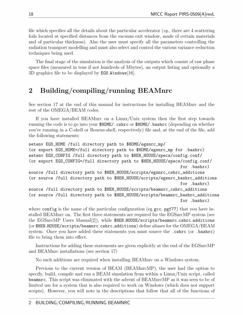
18 NRCC Report PIRS-0509(A)revL
file which specifies all the details about the particular accelerator (eg., there are 4 scatteringfoils located at specified distances from the vacuum exit window, made of certain materialsand of particular thickness). Also the user must specify all the parameters controlling theradiation transport modelling and must also select and control the various variance reductiontechniques being used.
The final stage of the simulation is the analysis of the outputs which consist of raw phasespace files (measured in tens if not hundreds of Mbytes), an output listing and optionally a3D graphics file to be displayed by EGS Windows[16].
2 Building/compiling/running BEAMnrc
See section 17 at the end of this manual for instructions for installing BEAMnrc and therest of the OMEGA/BEAM codes.
If you have installed BEAMnrc on a Linux/Unix system then the first step towardsrunning the code is to go into your $HOME/.cshrc or $HOME/.bashrc (depending on whetheryou’re running in a C-shell or Bourne-shell, respectively) file and, at the end of the file, addthe following statements:
setenv EGS_HOME /full directory path to $HOME/egsnrc_mp/
(or export EGS_HOME=/full directory path to $HOME/egsnrc_mp for .bashrc)
setenv EGS_CONFIG /full directory path to $HEN_HOUSE/specs/config.conf/
(or export EGS_CONFIG=/full directory path to $HEN_HOUSE/specs/config.conf/
for .bashrc)
source /full directory path to $HEN_HOUSE/scripts/egsnrc_cshrc_additions
(or source /full directory path to $HEN_HOUSE/scripts/egsnrc_bashrc_additions
for .bashrc)
source /full directory path to $HEN_HOUSE/scripts/beamnrc_cshrc_additions
(or source /full directory path to $HEN_HOUSE/scripts/beamnrc_bashrc_additions
for .bashrc)
where config is the name of the particular configuration (eg gcc, pgf77) that you have in-stalled BEAMnrc on. The first three statements are required for the EGSnrcMP system (seethe EGSnrcMP Users Manual[2]), while $HEN HOUSE/scripts/beamnrc cshrc additions
(or $HEN HOUSE/scripts/beamnrc cshrc additions) define aliases for the OMEGA/BEAMsystem. Once you have added these statements you must source the .cshrc (or .bashrc)file to bring them into effect.
Instructions for adding these statements are given explicitly at the end of the EGSnrcMPand BEAMnrc installations (see section 17)
No such additions are required when installing BEAMnrc on a Windows system.
Previous to the current version of BEAM (BEAMnrcMP), the user had the option tospecify, build, compile and run a BEAM simulation from within a Linux/Unix script, calledbeamnrc. This script was eliminated with the advent of BEAMnrcMP as it was seen to be oflimited use for a system that is also required to work on Windows (which does not supportscripts). However, you will note in the descriptions that follow that all of the functions of
2 BUILDING/COMPILING/RUNNING BEAMNRC
BEAMnrc Users Manual 19
the beamnrc script can be performed (in a much more user-friendly manner) from within theBEAM GUI.
2.1 “Specifying” Accelerators
Before compiling and running a BEAM accelerator simulation, you must “specify” whichcomponent modules are to be used and in what order. The available CMs are discussedin detail in section 15. Each CM can be used in a wide variety of applications and usershould not restrict themselves by the names. For example, the JAWS CM is well suited tosimulating a wedge. It is useful to select identifiers (8 characters or less) which are physicallymeaningful (eg xit win, scatfoil, jaws etc.) since these will appear throughout the code andlisting files and thereby help the user understand what is going on in various applications.The user may use the same CM as often as needed, as long as the identifiers used are unique.One restriction is that the identifier name should not start with the word “exit” since theMORTRAN compiler gets confused with this.
Accelerators are stored in a very simple format in myaccel.module files that reside inthe user’s $EGS HOME/beamnrc/spec modules subdirectory (see Figure 3 above). When builtand compiled, the executable code will have the name BEAM myaccel, so it is useful to havemyaccel indicate the machine you are modeling.
The myaccel.module file created from scratch using the BEAM GUI (just select “Specifya new accelerator” from the “File” menu), or you can copy an existing .module file (eg oneof the examples included with the distribution) into myaccel.module and modify the latterfor your own purposes using an editor.
Any number of specified accelerators can coexist at the same time.
2.2 Building an Accelerator: The beam build Code
Once the accelerator has been specified, it must be “built”, which corresponds to concate-nating all of the relevant source code for the CMs and editing it to avoid duplicate variablenames (this is discussed below for those who need details). The resulting files are on theuser’s area and are $EGS_HOME/BEAM_myaccel/BEAM_myaccel_cm.mortran and$EGS_HOME/BEAM_myaccel/BEAM_myaccel_macros.mortran. Note that the name of the sub-directory and the file names themselves are just the name of the specification module withthe prefix BEAM_.
If you are modifying the code at all, an accelerator must be re-built every time any ofthe CMs are modified, but not when the main beamnrc.mortran code is modified.
An accelerator is built using the MORTRAN code beam build.mortran. The commandfor running this code to build the accelerator specified by myaccel.module is:
beam_build.exe myaccel
beam build.exe creates the BEAM myaccel cm.mortran and BEAM myaccel macros.mortran
files and puts them in the BEAM myaccel subdirectory (creating the subdirectory on the way
Last edited 2011/05/09 19:16:55 2.1 “Specifying” Accelerators

20 NRCC Report PIRS-0509(A)revL
if it does not already exist).
In addition, beam build creates the files Makefile, modules.make and sources.make
and puts them in the BEAM myaccel subdirectory. These files are used for compiling beam.More details are given in section 2.12.3, on page 31, below.
If the beam build utility has not already been compiled for your particular configuration(this may be the case if you have switched configurations after installing BEAMnrc), then be-fore typing the above command line, go into $HEN HOUSE/omega/beamnrc/tools/beam build
and type make. This will put a copy of the beam build.exe executable in the appropriatesubdirectory of $HEN HOUSE/bin.
2.3 Compiling an Accelerator using make
Once specified and built, the accelerator must be compiled. This requires using the MORTRAN
compiler (which is supplied as part of the EGSnrc system) followed by the FORTRAN compiler.
In previous versions of BEAM, compiling of accelerators was completely driven by Unixscripts. However, with the necessity to run on non-Unix platforms, EGSnrcMP now uses theGNU make utility. For more detailed information on make, see the EGSnrcMP manual [2].
To compile an accelerator, go into the BEAM myaccel subdirectory and type:
make [options]
The options for make are:
make Compile the accelerator executable with default optimization
make opt turned on. Default optimization is level 3 (-O3).
make noopt Compile the accelerator executable with optimization
turned off.
make debug Compile an accelerator executable for debugging.
make fortran Do mortran compilation only, leaving behind the fortran
file BEAM\_myaccel\_config.F.
make clean Remove the fortran file, mortjob file, mortlst file
and the various executables.
Upon typing make you will see output to the screen indicating files that are being con-catenated together to create the final .mortran code that is then compiled.
After compiling an accelerator, the following files will be left behind:
In the accelerator directory:
mortjob.mortran The concatenated MORTRAN file which is MORTRAN compiled.
2 BUILDING/COMPILING/RUNNING BEAMNRC 2.3 Compiling an Accelerator using make

BEAMnrc Users Manual 21
BEAM myaccel config.mortlst Listing from the MORTRAN compiler. Contains theconcatenated MORTRAN code, formatted with levels of loops and IF blocksindicated. Output at the end of the file indicates if there were any MORTRANerrors and, if so, how many and of what type.
BEAM myaccel config.F Fortran output from the MORTRAN compiler. This is thef77 code that is ultimately Fortran compiled. The use of capital “F” indicatesthat some C routines are to be linked with the Fortran code at compile time. Inthe case of BEAM, these C routines pertain to parallel job submissions.
In the $EGS HOME/bin/config directory:
BEAM myaccel* The executable code.
If none of the MORTRAN source coding or macros have changed since the last compila-tion and the file BEAM myaccel config.F exisits in the accelerator directory and there is anexecutable in your $EGS HOME/bin/config directory, then typing make will not recompilethe accelerator.
If you want to include the beam characterization source in the accelerator, see the in-structions in section 4.16 page 83.
2.3.1 Compiling an Accelerator as a Shared Library
DOSXYZnrc[15] and other EGSnrc user codes[19] allow the user to use a full BEAM simu-lation as a particle source (instead of a stored phase space file). In order to use this source,the BEAM accelerator code must first be compiled as a shared library.
Once an accelerator has been built, it can be compiled as a shared library by going into$EGS HOME/BEAM myaccel and typing:
make library
The codes concatenated to create the mortjob.mortran file are the same as those used fora standard BEAM compilation with the exception that$OMEGA HOME/beamnrc/beam lib.mortran is used in place of$OMEGA HOME/beamnrc/beam main.mortran (see section 2.12.4, page 33). The library com-pilation also leaves behind libBEAM myaccel config.mortlst (output from MORTRANcompiler) and libBEAM myaccel config.F (Fortran source code), where config is the nameof your configuration.
The BEAM shared library is archived as the file libBEAM myaccel.so (for unix/Linuxmachines) or BEAM myaccel.dll (for Windows machines) in directory $EGS HOME/bin/config.
Note that previous versions of BEAMnrc required the static g2c library, libg2c.a, whencompiling shared libraries on Unix/Linux machines. Use of this library prevented confusionof I/O units between BEAM and the code using BEAM as a source (the “driving” code).In the current version of BEAMnrc, however, the opening of I/O units has been recoded sothat only those units not already being used by the driving code are available to BEAMnrc.
Last edited 2011/05/09 19:16:55 2.3 Compiling an Accelerator using make

22 NRCC Report PIRS-0509(A)revL
When using the BEAM shared library as a source, you must also supply a workinginput file and the pegs data for the BEAM simulation. The input file must exist in your$EGS HOME/BEAM myaccel directory and be set up to write a phase space file at a scoringplane. See the DOSXYZnrc Manual[15] and the manual for EGSnrc user codes[19] for moredetails about this source.
2.4 Compiling an Accelerator using mf (Unix/Linux specific)
To preserve compatibility with old usage, an accelerator can also be compiled using mf, whichis aliased to the Unix script $HEN HOUSE/scripts/compile user code. To compile usingmf, go into the BEAM myaccel directory and type:
m[f] BEAM_myaccel [a] [opt|noopt|debug]
The options for mf are: mf => Mortran and Fortran compile and then linkm => Mortran compile and create the Fortran fileopt => use optimizationnoopt => use no optimizationdebug => create executable ready for a debug runThe parameter “a” is not used and is only present for compatibility with the previous versionof mf.
Once the mf command is issued, the compile user code script then calls make with theappropriate options.
2.5 Building/Compiling with the BEAM GUI
Building and compiling are done in a single step when using the BEAM GUI. Once an ac-celerator .module file has been specified or read into the GUI, then it can be built/compiledby selecting “Compile” from the “Execute” menu. This opens up a window in which youcan choose any of the make options outlined in section 2.3 above. Then press the “BUILD &COMPILE” to run beam build followed by make. If there is no beam build.exe* executablein the appropriate $EGS HOME/bin/config directory, then the GUI will automatically com-pile beam build for your configuration.
2.6 Internal Documentation and Input Description
Since a given accelerator model can have an arbitrary structure, defining the input file for agiven accelerator must be done after the accelerator is specified. Extensive descriptions of themain BEAM inputs and individual CM inputs are given at the top of the beamnrc.mortran
and CM cm.mortran codes, however the BEAMnrc graphical user interface (GUI) providesextensive descriptions of each input variable in addition to being able to display graphicalrepresentations of component module and accelerator geometries as input by the user. Thus,the GUI is the preferred method for generating input files. For more information on theBEAMnrc gui, see the BEAMnrc, DOSXYZnrc and BEAMDP GUI User’s Manual[20].
2 BUILDING/COMPILING/RUNNING BEAMNRC2.4 Compiling an Accelerator using mf (Unix/Linux specific)

BEAMnrc Users Manual 23
2.7 Running an Accelerator Simulation
Once the accelerator model is compiled, the user may run a simulation. To run a simulationfrom the command line, type:
BEAM_myaccel -i inputfile -p pegsdata
where inputfile is the name of the BEAM inputfile (with no .egsinp extension) andpegsdata is the name of the PEGS4 material data file (with no .pegs4dat extension).These two files are discussed in more detail below.
To preserve compatibility with old usage, accelerators can also be run with the “ex”command:
ex BEAM_myaccel inputfile pegsdata
“ex” is aliased to the Unix script $HEN HOUSE/scripts/run user code. This script uses thenon-script command line shown above to actually run the accelerator, but first it checks forthe existence of the relevant directories ($EGS HOME and the BEAM myaccel subdirectory). Italso checks for the existence of the BEAM myaccel* executable and compatibility between theconfig.conf file you are using and the actual configuration that you are running on.
The users input file, i.e. inputfile.egsinp, defining the geometry of the accelerator andthe BEAM simulation parameters, must exist in $EGS_HOME/BEAM_myaccel. The best wayfor a new user to begin creating a new input file is to use the BEAM GUI[20]. From theGUI, you can either begin a new input file from scratch or read in an existing input file (forthe same accelerator) and modify the parameters accordingly. More experienced users mayfind it faster to use an editor to modify an existing input file.
Note that the input file extension is .egsinp. Theoretically, BEAMnrc can run aBEAM00 .egs4inp input file, however, depending on the parameters, there may be newinputs that will cause an error on reading the older file. It is safer to read the old .egs4inp
file into the GUI and resave it. The GUI will then write to the file all the necessary inputs forthe current version of BEAM. Note that .egs4inp files do not contain any EGSnrc transportparameter inputs, so standard BEAMnrc defaults for these parameters will be used whenolder files are read into the GUI and/or used in a BEAM simulation.
Much of the rest of this document is devoted to discussing the meaning of all the optionsavailable through the input file.
In order to run an accelerator, you also have to enter the name of the .peg4dat filecontaining the cross section data for the materials in the model. Note that all of the materialnames used in the input file must exist in the .pegs4dat file used. There is more informationin section 16 but basically the files 700icru.pegs4dat and 521icru.pegs4dat contain datafor a large number of commonly used materials. The numbers in the names correspond toAE=521 and AE=700, i.e. thresholds for secondary electron production of 10 and 189 keVkinetic energy respectively. The data sets go up to 55 MeV in both cases. These data setsare on the distribution on area $HEN_HOUSE/pegs4/data. If the user wishes to make theirown data files using the program PEGS4, these files can be put either on that area, or onthe user’s pegs4 area, viz. $EGS_HOME/pegs4/data.
Last edited 2011/05/09 19:16:55 2.7 Running an Accelerator Simulation

24 NRCC Report PIRS-0509(A)revL
2.7.1 Batch Runs
Thus far, we have described interactive BEAM runs, in which the BEAM input and jobexecution information is echoed to the screen and where the window in which the job isrunning cannot be used for anything else while the job is executing. However, if you arerunning on a Unix/Linux system, then it is often desirable to run simulations in batch mode.For example, batch job submission can make use of a network queuing system (eg PBS orNQS) and is required for parallel jobs (see section 13 in this manual for more informationon parallel jobs).
Submitting a batch job uses the exb command, which is aliased to the Unix script$HEN HOUSE/scripts/run user code batch. The syntax of the exb command is:
exb BEAM_myaccel inputfile pegsdata [short|medium|long] [batch=batch_system] [p=N]
The input [short|medium|long] determines the name of the queue to be used (thedefault is long). With our naming system at the NRC, the short queue has the lowestmaximum CPU time but the highest priority, while long has an unlimited CPU time withlowest priority.
The batch=batch system input determines the name of the queuing system to use. Therun user code batch script sources the file $HEN HOUSE/scripts/batch options.batch system,which defines the batch submission commands for the particular queuing system chosen andmay redefine the names of the queues available on that system (this means that the queuenames short|medium|long are not necessarily general). Currently, batch system can be setto at (the standard Unix batch command), pbs (for the PBS queuing system) or nqs (for theNQS queuing system). This means that the files batch options.at, batch options.pbs
and batch options.nqs are included with the EGSnrcMP distribution. However, the batchsubmission commands in these files are for our system at the NRC and you may have tomake some changes for your system. The default value for batch system is at, unless youhave the environment variable $EGS BATCH SYSTEM set to something else.
Finally, the p=N input is used if you want to split the simulation into N parallel jobs. Formore information on parallel runs, see section 13, page 123.
In addition to the files which are output from an interactive accelerator simulation, abatch run will also output a inputfile.egslog and file and a inputfile.eo file. The.egslog file contains all the output that would be echoed to the screen during an interactiverun. IT IS IMPORTANT TO LOOK AT THE .egslog FILE TO SEE IF ANYINPUT OR RUN TIME ERRORS OCCURRED. The .eo file contains messagesfrom the queuing system. If, for some reason, a job did not get submitted properly, thenthis file may contain clues to the problem. More information on BEAM output files is givenin section 2.10, page 25 below.
For more information on submitting batch jobs, see the EGSnrcMP manual [2].
2 BUILDING/COMPILING/RUNNING BEAMNRC 2.7 Running an Accelerator Simulation
BEAMnrc Users Manual 25
2.8 Running BEAMnrc using the GUI
It is possible to use the BEAM GUI to submit interactive, and if your system is set to handlebatch jobs, batch and parallel runs. To do this, select “Run” from the “Execute” menu. Thisopens a running window which will give you the option to switch from an interactive to abatch (and parallel) run, and will allow you to select the queue you wish to run on. Ifyou have not set the environment variable $EGS BATCH SYSTEM, then the GUI automaticallysubmits to a PBS network queuing system (ie sets batch system=pbs). When you press the“Execute” button, the GUI then assembles and executes the appropriate command line asdescribed in the sections above. Output which would normally appear on the screen duringan interactive run is now displayed in the GUI running window.
2.9 A Note on Temporary Working Directories
Before a BEAM run (batch or interactive), a temporary working directory,$EGS HOME/BEAM myaccel/egsrun pid inputfile hostname is created, where pid is theprocess ID number, inputfile is the name of the input file (no .egsinp extension), andhostname is the name of the computer the job is running on. All output files from a run(more about output files in the next section) are written to this directory with the exceptionof phase space (.egsphsp#) files, which are written directly to the $EGS HOME/BEAM myaccel
directory. Once the run is finished, all output files are moved from$EGS HOME/BEAM myaccel/egsrun pid inputfile hostname into $EGS HOME/BEAM myaccel
directory and the temporary working directory is removed. The reason phase space files arewritten directly to the accelerator directory is that they often end up being large, whichmakes moving them from one directory to another time consuming. If, for some reason, thesimulation terminates prematurely, the temporary working directory, containing its outputfiles, will be left behind.
2.10 BEAMnrc Output Files
Each of the BEAM output files that will be found in your $EGS HOME/BEAM myaccel directoryat the end of a run is described briefly below.
.egslst This may be considered the “main output file” because it contains all of the doseand fluence results of the simulation. The file is broken up into different sections:
Error and Warning Messages Most error and warning messages that appear onscreen (or in the log file) during input are repeated at the top of the listing file.
Summary of the Main BEAMnrc Inputs This section summaries those inputsthat are not CM-specific, such as the number of histories to run, photon forc-ing inputs, etc.. The section also includes some characteristics of a phase spacesource (if used), such as the total number of particles in the source, the maximumkinetic energy of the source, etc.. If range rejection was chosen, this section alsocontains a table of maximum electron range versus electron energy for the variousmaterials to be used in the simulation.
Last edited 2011/05/09 19:16:55 2.8 Running BEAMnrc using the GUI

26 NRCC Report PIRS-0509(A)revL
Material Data Shows relevant data (density, AE, AP, etc.) for all materials used inthe simulation as read from the .pegs4dat file.
Source Parameters This is a summary of parameters such as the type of source, theZ location of the face on which the source is incident, etc. For a phase spacesource, this section repeats the source characteristics found in the first section ofthe file.
Region and Range Rejection Summary This is a very useful summary of all ofthe regions in the simulation. Regions are identified by both their absolute andlocal numbers. The absolute region number identifies the region within the entiresimulation geometry, the local region number identifies the region within its owncomponent module. The region summary indicates what component module aregion is in, the dose zone number and bit number the user has assigned to aregion (called the “bit region”) and the material that the user has specified theregion to be made of. If range rejection is turned on, this summary also containsthe value of ECUTRR (the minimum energy an electron must possess in a region inorder for it to reach the bottom of the simulation geometry) the residual rangeand the value of ESAVE (maximum electron energy at which range rejection isconsidered) for each region.
Component Module Summary This section of the listing files summaries the ge-ometry and region information for each component module in the order that thecomponent modules appear in the simulation geometry. This section is useful formaking sure that the geometry, as interpreted by BEAMnrc, is the same as thegeometry the user intended to input. This section gives specific dimensions of acomponent module and the specific location of each region within a componentmodule. For each region, ECUT, PCUT, ECUTRR, ESAVE, the material, the dose zone,and the bit number are output. There is enough information in the componentmodule summary to reconstruct the input file.
Execution Information and Warning Messages This section contains a post-runsummary of some relevant run-specific information, such as the elapsed and CPUtime required for the run, the total number of charged particle steps, the fractionof steps for which multiple scattering was switched off, etc. When a phasespace source is used, this section contains a summary of the source characteristics(number of electrons, number of photons, maximum energy, etc.) determinedfrom those particles actually used in the simulation. Some warning messages,such as those printed when all particles in a phase space source have been usedand the source must be restarted with the first particle, are printed in this section.
Number, Fluence, Average Energy and Average Angle Results This sectionsummaries the results for all scoring planes in the geometry. BEAMnrc outputsa summary of each scoring plane, including the plane’s Z-position, the number ofparticles that crossed it, and the radii (half-widths) of the scoring zones, followedby the actual fluence results for the plane. The fluence is taken as the weightedsum of 1/cosθ where θ is the angle of the particle with respect to the z-axis. Thenumber averaged energy and number averaged angle are also output. Scoringzones are numbered in order of increasing radius (half-width). Note that thefluence results may be output for one more scoring zone than the number of
2 BUILDING/COMPILING/RUNNING BEAMNRC 2.10 BEAMnrc Output Files

BEAMnrc Users Manual 27
scoring zones input by the user. This “extra” scoring zone represents the area ofthe scoring plane not covered by the scoring zones. Fluence results for particlescrossing the scoring plane only once and those for particles crossing the plane twoor more times (“multiple passers”) are output separately. Note that all relevantresults (number, fluence, dose, energy deposited) are normalized per initial sourceparticle in the entire accelerator model, i.e. per initial particle which is not froma phase space file. This is done by using the variable NINCPHSP discussed insection 7.1. one advantage of this method is that the same results are obtainedautomatically, whether the calculation is split up into several components or not.
Dose Results The first table shows the total dose and total energy deposited in eachof the dose scoring zones set up in the accelerator. Note that each dose scoringzone may include several geometric regions. The second table (if contaminant dosecalculations are asked for) shows the dose in each region due to the contaminantparticles which are defined as the charge state selected by the user as the particlescross a certain planar boundary. This was designed for calculation of dose in aphantom but is applied in general. Finally, the doses in each region with bitfilters applied are given. Note that these dose components are not exclusive; thatis, dose components from particles that have been in a specified scraper includecontributions from particles that have been in other scrapers before and/or afterpassing through/interacting in the specified scraper.
.egslog The log file (created only for a batch run) contains all of the dialogue that wouldbe appear on the screen during an interactive run. Thus, input parameters are echoedand any input errors will appear here. Below the input is a summary of the mate-rials in the simulation (and whether or not Rayleigh scattering data is available foreach material), a summary of PRESTA parameters, followed by the run-time executionmessages (number of histories completed, CPU time for a batch, warning and errormessages, etc.). After completion of a batch job, looking in the log file is often theeasiest way to make sure that all histories were completed and that no run-time errors,such as endless loops, or negative USTEP errors, occurred. When using a phase spacefile for the source, the log file contains a warning line every time the particles in thephase space source are all used and the source file is reused from the beginning.
.egsdat This file contains all of the information required to restart a run and also theinformation required to obtain dose and fluence when parallel jobs are recombined.Data stored in the .egsdat file include:
1.∑nhist
i=1 (energy deposited)i,∑nhist
i=1 (energy deposited)2i ,
∑nhisti=1 (fluence)i, and∑nhist
i=1 (fluence)2i in each dose and fluence scoring zone, where nhist is the number
of primary (non-phase space) histories completed.
2. elapsed CPU time
3. no. of histories completed, no. of primary histories completed
4. state of the random number generator at the end of the last batch
When a run is restarted, BEAMnrc reads the energy deposited and fluence data (item 1above) for the previous run from the .egsdat file and then adds it to the current results
Last edited 2011/05/09 19:16:55 2.10 BEAMnrc Output Files
28 NRCC Report PIRS-0509(A)revL
before calculating doses, fluence values and uncertainties [17]. When recombiningparallel jobs, BEAMnrc reads the energy deposited and fluence data for each paralleljob from its .egsdat file, sums the data across all jobs and (without running any furthersimulations) calculates the doses, fluence values and uncertainties for the completesimulation. See section 10.3 about the input variable IRESTART and Section 13about parallel runs.
.egsrns This file contains the complete state of the random number generator at the startthe current batch (ISTORE=0) or current history (ISTORE=1) in a simulation. This isonly used for debugging problems which occur. These data are used to restart the runwith this RNG when ISTORE is set to -1.
.egsplot This file contains dose vs depth for all dose components when a CHAMBER CMis used as a depth dose phantom. The format of the file is suitable for plotting withxmgr or xmgrace. Note that the output of the file only makes sense for doses scored ina CHAMBER depth dose phantom.
.egsphsp1(2 or 3) These files contain phase space information (see section 7) for all parti-cles crossing the scoring planes. If IO_OPT is set to 1 (see section 10.4), no phase spaceis scored, and these files are empty.
.egsgeom If a graphical output is requested (IWATCH=4), this file specifies the acceleratorgeometry for display by EGS Windows [16].
.egsgph If a graphical output is requested, this file contains the track histories for displayby EGS Windows. Note that this file becomes large for even a few 10’s of histories.
.errors Lists any errors in the EGSnrc transport parameter inputs. The contents of this fileare generated by the code $HEN HOUSE/src/get inputs.mortran, which takes care ofreading the EGSnrc transport parameter inputs in BEAM (and other user codes).
.eo Contains output from the network queuing system (batch job submissions only).
Since the .egsphsp files are often very large, and may exceed the available disk space,BEAMnrc provides options for changing the output directory for .egsphsp files from thedefault output directory, $EGS HOME/BEAM myaccel (see Section 7.2 for more information).Changing the output directory for the other output files, however, is more complicated, andinvolves going into $HEN HOUSE/src/egs utilities.mortran and changing the directorypath specified in subroutine egs open file.
2.11 Changing the defaults
At the top of the .egslog file, there is a list of 10 user selectable internal parameters whichthe user may wish to vary. These are all found in$OMEGA_HOME/beamnrc/beamnrc_user_macros.mortran along with 10 or so other parame-ters you may change.
2 BUILDING/COMPILING/RUNNING BEAMNRC 2.11 Changing the defaults

BEAMnrc Users Manual 29
The following internal parameters are set:
Max number of CMs: 20 Max number of media 12
Max number of regions: 250 Max stack: 10000
Max bremsstrahlung split: 2000 Max number dose zones: 50
Max number of scoring planes: 3 Max number of scoring zones: 5
Max number dose components: 12 Minimum air gap: 0.0100 cm
All of above can be adjusted in beamnrc_user_macros.mortran
Some of these parameters are obviously correlated, so eg. the Max stack should havea value at least 4 times greater than Max bremsstrahlung split. Nonetheless, the usershould feel free to vary these parameters if they need to. The default settings should be OKusing directional bremsstrahlung splitting.
Once any of the parameters in beamnrc user macros.mortran have been changed, theaccelerator must be recompiled to make the changes effective.
On a stand alone system you may be able to change$OMEGA HOME/beamnrc/beamnrc user macros.mortran but this change will affect all accel-erator models recompiled after that. If you wish to make the change for just one accelerator,then copy $OMEGA HOME/beamnrc/beamnrc user macros.mortran to the directory of the lo-cal accelerator, make the changes in that copy and then edit the sources.make file and delete$(BEAM HOME) before beamnrc user macros.mortran. When the accelerator is recompiled,it will pick up the new version of beamnrc user macros.mortran.
2.12 Some Details
This section can be skipped without problems for new users.
2.12.1 The BEAM myaccel.io File
This file (which is a renamed copy of $OMEGA HOME/beamnrc/default beam.io) is put intoyour BEAM myaccel directory by beam build when you build your accelerator. This filecan be used to associate file names with Fortran unit numbers. In the current versionof BEAMnrc, all output files (eg .egsphsp#, .egsdat, .egsplot, etc) are opened ex-plicitly from within the code and so the default BEAM myaccel.io is empty (except forcomments at the top). However, the file is useful if you wish to customize BEAMnrc towrite your own output quantities. For example, if you wish to output QUANTITY to the fileinputfile.myoutput, the easiest way is to go into beamnrc.mortran and add statements,WRITE(UNIT,FORMAT)QUANTITY; (where UNIT is an arbitrary Fortran unit number), whererequired and then add the line:
UNIT .myoutput
to the BEAM myaccel.io file (Note that the only the file extension needs to be specified).
Files specified in BEAM myaccel.io are opened at the beginning of the simulation andare not closed until the simulation has completed. Moreover, the files specified here areALWAYS opened (ie there are no conditions on whether the file is created or not), so if no
Last edited 2011/05/09 19:16:55 2.12 Some Details

30 NRCC Report PIRS-0509(A)revL
quantity is written an empty file will be created. For more information about .io files, seethe EGSnrcMP Manual [2].
2.12.2 What’s in BEAM myaccel macros.mortran and BEAM myaccel cm.mortran
The file BEAM myaccel macros.mortran, created by beam build when you build an acceler-ator, comprises the following code (in this order):
• beamnrc cm macros.hdr. Copied from $OMEGA HOME/beamnrc, this is a short headerfile with nothing but comments.
• $CM LIST macro. This macro has the form:
REPLACE{$CM_LIST} WITH {CMLIST(
CMID1,
CMID2,
CMID3,
CMID4
)}
where CMID1 is the identifier for the first CM, CMID2 is the identifier of the secondCM, etc., as specified in the myaccel.module file. This is ultimately expanded duringMORTRAN compilation of the accelerator to generate a list of CM identifiers (ieCMLIST(1)=’CMID1’, etc) which is used in many places in the BEAM code.
• $CM TYPE macro, which has the form:
REPLACE{$CM_TYPE} WITH {CMTYPE(
CM1,
CM2,
CM3,
CM4
)}
where CM1 is the name of the first CM (eg SLABS), CM2 is the name of the second CM,etc, as specified in myaccel.module. During MORTRAN compilation, this macro getsexpanded to a list of CM names (ie CMTYPE(1)=’CM1’, etc), which is used in manyplaces in the BEAM code.
• CM macros.mortran for each CM in the accelerator model (in the order in which theyappear in the myaccel.module file) with CM replaced by the CM identifier as speci-fied in myaccel.module. The CM macros.mortran files are copied from the directory$OMEGA HOME/beamnrc/CMs. Note that even if a given CM is used more than once inan accelerator, a CM macros.mortran file for each occurence of the CM will be copiedinto BEAM myaccel macros.mortran, but, of course, the identifier used to replace CM
will be different in each case.
2 BUILDING/COMPILING/RUNNING BEAMNRC 2.12 Some Details
BEAMnrc Users Manual 31
The BEAM myaccel cm.mortran file, also created by beam build when you build an accel-erator, consists of the CM cm.mortran files for every CM in the accelerator (in the order speci-fied in myaccel.module) with CM replaced by the CM identifier specified in myaccel.module.Similar to BEAM myaccel macros.mortran, even if a CM occurs more than once in the ac-celerator, CM cm.mortran is copied into BEAM myaccel cm.mortran for every occurence ofthe CM, but the identifier in each case will be different. The CM cm.mortran files are copiedfrom $OMEGA HOME/beamnrc/CMs.
2.12.3 Files used during Compilation with make
The make command uses several different files to direct the concatenation and compilationof the final MORTRAN code. This section those files, along with their functions, which arelikely to be relevant to BEAM users. For a more complete description of the files involvedin the make command, see the EGSnrcMP manual [2].
Makefile Located in the BEAM myaccel subdirectory and created by beam build when theaccelerator is built. This provides the “overall” instructions for compilation. It tellsthe compilation to include the $HEN HOUSE/specs/config.conf for your particular“config” (ie gcc, pgf77, Windows, etc). It also instructs the compilation to include thefiles $HEN HOUSE/specs/beamnrc.spec and $HEN HOUSE/makefiles/beam makefile.Finally it defines the name of the accelerator (ie myaccel) for use in other files.
config.conf Located in the $HEN HOUSE/specs subdirectory, where config is the name ofthe configuration you are running (eg gcc, pgf77, win2k, etc). This file contains manydefinitions essential for compiling all user codes. Definitions include:
• DSEP The directory separator for your machine (”/” for Unix/Linux, ”” for Windows).
• my machine The name of your machine.
• make prog The make command used on installation.
• Definitions of $HEN HOUSE, $EGS HOME and $SPEC DIR (directory where the config.conffile is found)
• Definitions of the f77 and C compilers to be used, along with the default compileroptions (eg optimization levels).
Other variables defined in config.conf include:
• CUTIL OBJECTS Object files compiled from the C utility codes (such as file lockingfunctions, etc) linked with BEAM at compile time. On Unix/Linux, machinesthis will point to egs c utils.o if you have a working C compiler and is emptyotherwise. On Windows machines, CUTIL OBJECTS will point to egs c utils.obj,a precompiled object file that eliminates the need to have a working C compilerwhen using these functions on a Windows machine.
• BEAMLIB OBJECTS The object file required at compilation if a user code (suchas DOSXYZnrc) is to use a BEAM shared library as a source. On Unix/Linux
Last edited 2011/05/09 19:16:55 2.12 Some Details

32 NRCC Report PIRS-0509(A)revL
systems, BEAMLIB OBJECTS will point to load beamlib.o if you have a working Ccompiler, and will be empty otherwise. On Windows machines BEAMLIB OBJECTS
will point to load beamlib.obj, which is a precompiled object file and elminatesthe need to have a C compiler when using a BEAM library source on a Windowsmachine.
• BEAMLIB EXTRA LIBS The library required at compilation if a user code is to beable to use a BEAM shared library source (-ldl on Unix/Linux machines witha working C compiler, nothing otherwise), and also $(IAEA LIB), which, if set,points to the library required for a user code to use IAEA-format phase space filesas sources (see next item).
• IAEA LIB and IAEA PHSP MACROS Variables defining the library of IAEA phasespace handling routines (IAEA LIB) and the Mortran macros which use these rou-tines (IAEA PHSP MACROS). If your system does not have a working C++ compiler,then the IAEA phase space handling routines cannot be compiled and these twovariables will be left blank. Variables are used during the compilation of BEAM-nrc and other EGSnrc user codes and must be defined in order to be able toread/write phase space data in IAEA format.
The config.conf file also instructs compilation to include the files$HEN HOUSE/specs/[unix.spec or windows.spec] and$HEN HOUSE/specs/all common.spec described below.
unix.spec or windows.spec Contains definitions (such as the extension to add to an exe-cutable file) unique to Unix or Windows.
all common.spec Contains definitions common to all systems. This including the mortransources and macros required to compile a generic EGSnrcMP user code. This file alsodefines the variable RANDOM, for the random number generator, but the definition ofRANDOM in beamnrc.spec (see below) overrides this one.
beamnrc.spec Located in the $HEN HOUSE/specs subdirectory, this file contains definitionsrequired for compiling codes in the BEAM system. Among these are the definitionsof directories, $OMEGA HOME, $BEAM HOME, $DOSXYZ HOME and $CM HOME. beamnrc.specalso defines the extension, FEXT to add to the Fortran code output by the MORTRANcompiler. Currently, FEXT = F, which instructs the compiler to use the C-preprocessorbefore compiling the code. This is necessary for the new implementation of parallelprocessing in BEAM. If, for some reason, you do not have a C compiler on yoursystem, then the installation will set FEXT = f. In addition, the variable SOURCES inbeamnrc.spec defines all the MORTRAN macros and codes to concatenate and theorder in which to concatenate them to create the final mortjob.mortran file that isthen Fortran compiled (see section 2.12.4 below for more details). beamnrc.spec alsodefines the variable LIB SOURCES, which lists the macros and codes (in order) that areconcatenated to create the mortjob.mortran when BEAMnrc is compiled as a sharedlibrary for use as a source in DOSXYZnrc and other user codes (see section 2.3.1for more information). In practice, the definitions of SOURCES and LIB SOURCES arecopied into a file called sources.make in the accelerator directory when the acceleratoris built, and these latter definitions supersede those in beamnrc.spec (see below for
2 BUILDING/COMPILING/RUNNING BEAMNRC 2.12 Some Details

BEAMnrc Users Manual 33
more about sources.make). Finally, beamnrc.spec defines the variable RANDOM,which determines the random number generator to be used in the simulation. Tworandom number generators, RANLUX and RANMAR are included in the EGSnrcMP system.Currently, RANMAR is the default random number generator. See section 10.8 for moreinformation about the random number generators and how to switch from the defaultRANMAR to RANLUX.
beam makefile Located in $HEN HOUSE/makefiles, this defines the final compilation of theMORTRAN and Fortran codes. All of the make options outlined above are taken careof here. In addition, this file sources the files$EGS HOME/BEAM myaccel/modules.make and $EGS HOME/BEAM myaccel/sources.make
created when the accelerator was built (more about these files below). beam makefile
ensures that the accelerator will be recompiled if there is a change in any of the MOR-TRAN code or macro files used by the accelerator (these are compiler “dependencies”).beam makefile also automatically rebuilds (by calling beam build.exe) the accelera-tor if there is a change in any of the individual CM macros or MORTRAN codes or ifmyaccel.module has been changed to use different CMs and/or CM identifiers (theseare build “dependencies”).
modules.make Located in $EGS HOME/BEAM myaccel and created by beam build when theaccelerator is built. This file is a list of the MORTRAN codes($HEN HOUSE/omega/beamnrc/CMs/CM cm.mortran) and macros$HEN HOUSE/omega/beamnrc/CMs/CM macros.mortran) for all CMs used in the accel-erator. It is through the modules.make file that beam makefile has access to theindividual CM macros and MORTRAN codes and can, thus, rebuild the accelerator ifany of the CM coding changes. The user should not modify this file since it
sources.make Located in $EGS HOME/BEAM myaccel and created by beam build when theaccelerator is built. This file contains definitions of the variables SOURCES and LIB SOURCES
copied from the beamnrc.spec file (see above). These definitions override those inbeamnrc.spec and allow the user to customize their accelerator, adding their ownsource code and/or changing the directory from which source codes are picked up.Note when adding your own coding that macros must appear above the MORTRANcoding they are used in and, in the case where there are several occurrences/versionsof the same macro, the last occurrence is the one that is used. Note that changes madeto this file will be lost if you execute beam build or build the accelerator using theGUI. This file must be adjusted to include source 31 for beam characterization (seesection 4.16.
2.12.4 Files Concatenated to Create mortjob.mortran
mortjob.mortran, the file which is actually MORTRAN compiled on the way to creating anexecutable for your accelerator, consists of many concatenated macros and MORTRAN files.The files which are concatenated and the order in which they are concatenated are determinedby the SOURCES (for stand-alone accelerators) or LIB SOURCES (for shared libraries) defini-tion in the file $EGS HOME/BEAM myaccel/sources.make discussed in section 2.12.3 above.
Last edited 2011/05/09 19:16:55 2.12 Some Details

34 NRCC Report PIRS-0509(A)revL
Figure 5 below shows all the files that are concatenated to create a mortjob.mortran for astand-alone accelerator simulation.
Note that macros must appear before the MORTRAN code in which they are used.Hence, the first portion of mortjob.mortran consists entirely of macro files.
HEN_HOUSE/src/get_inputs.mortranHEN_HOUSE/src/ranlux.mortran
(or HEN_HOUSE/src/ranmar.mortran)HEN_HOUSE/utils/nrcaux.macrosHEN_HOUSE/lib/config/machine.mortranHEN_HOUSE/src/egs_parallel.mortranHEN_HOUSE/src/egsnrc.mortran
HEN_HOUSE/src/egsnrc.macrosHEN_HOUSE/utils/timing.macrosHEN_HOUSE/lib/config/machine.macrosHEN_HOUSE/src/ranlux.macros(or HEN_HOUSE/src/ranmar.macros)
HEN_HOUSE/src/transportp.macros
OMEGA_HOME/sbsnrc_macros.mortranOMEGA_HOME/phsp_macros.mortranOMEGA_HOME/beamnrc_user_macros.mortran
EGS_HOME/BEAM_myaccel/BEAM_myaccel_macros.mortran
HEN_HOUSE/src/egs_utilities.mortran
EGS_HOME/BEAM_myaccel/BEAM_myaccel_cm.mortran
HEN_HOUSE/utils/xvgrplot.mortran
OMEGA_HOME/beamnrc.mortran
mortjob.mortran
MORTRAN code
macros
Figure 5: Files concatenated to form the complete BEAM source code, mortjob.mortran,where BEAM myaccel cm.mortran and BEAM myaccel macros.mortran contain the sourcecode related to all the selected CMs. The files and the order of concatenation are defined bythe SOURCES variable in $EGS HOME/BEAM myaccel/sources.make.
A brief description of each of these files follows:
egsnrc.macros Macros for the EGSnrc system. This includes common blocks, such asSTACK, that are used by all user codes. See the EGSnrc Manual[1] for more details.
timing.macros Definitions of timing macros used in BEAMnrc (and other user codes).Replaces the macros with calls to EGS subroutines used to determine elapsed CPUtime, elapsed total time, etc.
phsp macros.mortran Macros used by BEAMnrc to read/write data from/to phase spacefiles. See section 7 for more details.
iaea phsp macros.mortran Macros used by BEAMnrc to read/write phase space data inIAEA format. This file is only present if there is a working C++ compiler (required to
2 BUILDING/COMPILING/RUNNING BEAMNRC 2.12 Some Details

BEAMnrc Users Manual 35
compile the library of IAEA phase space handling routines). Otherwise, these macrosare defined as blank (“;”) in phsp macros.mortran and IAEA-format phase spacedata cannot be handled.
machine.macros Machine/compiler-dependent macros. Defines $LONG INT as integer*8 ifit is available on this machine, the record length factor ($RECL-FACTOR) for a 4-byterecord in a phase space file, etc. See the EGSnrcMP Manual[2] for more details.
ranmar.macros (or ranlux.macros) Macros used by BEAMnrc (and other user codes) toobtain random numbers, store random number states to a file, retrieve random numberstates from a file and initialize the random number generator.
transportp.macros Macros used by get inputs to define text patterns searched for in theEGSnrc input section of a BEAMnrc input file (see section 11).
beamnrc user macros.mortran Macros defining many default BEAMnrc parameters suchas the maximum number of dose/fluence scoring zones, the maximum stack depth, etc.These parameters often need to be changed by the user. See section 2.11 for moredetails.
sbsnrc macros.mortran Macros used by BEAMnrc when performing selective bremsstrahlungsplitting (SBS). See section 6.3.2 for more details.
BEAM myaccel macros.mortran Macros for all CMs that comprise myaccel concatenatedtogether by beam build with the names of the CMs replaced by their identifiers asspecified in the myaccel.module file. See section 2.2 for more details.
egs utilities.mortran Various EGSnrc utility codes. Includes the egs init functioningfor initializing variable arrays and opening any Fortran output units with the namesgiven in BEAM myaccel.io (see section 2.12.1). Also includes egs combine runs rou-tine for recombining results after parallel runs (see section 13.3).
beam main.mortran BEAMnrc main code. Consists of calls to the main BEAMnrc subrou-tines, beam init, beam shower loop and beam finish (in that order). These subrou-tines are in beamnrc.mortran (see below).
beam lib.mortran Used instead of beam main.mortran when compiling BEAMnrc as ashared library for use as a source (in DOSXYZnrc or other EGSnrc user code). Con-tains macro (re)definitions essential for use as a source along with subroutines forinitializing and sampling the BEAMnrc source. Among these is a redefinition of themain phase space writing macro which causes phase space data that would normallybe written to a phase space file to be stored in an array instead. Incident particles forthe simulation using the BEAMnrc simulation as a source are then sampled from thisarray.
beamnrc.mortran Contains definitions of macros used by BEAMnrc, common blocks usedby BEAMnrc and all BEAMnrc subroutines.
xvgrplot.mortran Subroutine for creating a data file suitable for plotting with xmgr/xmgrace.BEAMnrc uses this subroutine to output an .egsplot file (see section 2.10).
Last edited 2011/05/09 19:16:55 2.12 Some Details

36 NRCC Report PIRS-0509(A)revL
BEAM myaccel cm.mortran Subroutines for all CMs comprising myaccel concatenated to-gether by beam build with CM names replaced by their identifiers as specified inmyaccel.module. See section 2.2 for more details.
get inputs.mortran Coding for reading EGSnrc inputs from the BEAMnrc input file. Seesection 11 for more about these inputs.
ranmar.mortran (or ranlux.mortran) Subroutines used by the RANMAR (or RANLUX)random number generator. Many of the macros defined in ranmar.macros (or ranlux.macros)include calls to these subroutines.
nrcaux.mortran Auxiliary MORTRAN routines used by BEAMnrc (and other EGSnrcuser codes). Includes SUBROUTINE WATCH, which outputs details of each particlestep/interaction or particle tracks to the .egsgeom file for display using EGS Windows,depending on the value of the input variable IWATCH (see section 10.1 for more onIWATCH).
machine.mortran Machine/configuration-dependent routines such as date/time routinesand system calls. This file is created during EGSnrcMP installation. See the EGSnrcUsers Manual[1] and EGSnrcMP Users Manual[2] for more info.
egs parallel.mortran Subroutines for creating, opening, reading from and writing to thejob control (.lock) file during a parallel run (see section 13).
egsnrc.mortran EGSnrc subroutines. See the EGSnrc Manual[1] for more details.
Note that in previous versions of BEAMnrc, all of the BEAMnrc-specific coding wascontained in the file $OMEGA HOME/beamnrc/beamnrc.mortran. Now, however, this codinghas been broken up into two files: the BEAMnrc main code is in$OMEGA HOME/beamnrc/beam main.mortran, and the rest of the macro/subroutine defini-tions in $OMEGA HOME/beamnrc/beamnrc.mortran. Separating out the BEAMnrc main codewas necessary to allow us to compile BEAMnrc as a shared library for use as a source inDOSXYZnrc and other EGSnrc user codes, since shared libraries do not use the BEAMnrcmain code. See section 2.3.1 (page 21) for more information about BEAMnrc as a sharedlibrary.
3 Description of main BEAMnrc input file
The first section of an input file (.egsinp) for BEAMnrc concerns all issues not related toindividual CMs. The following is taken from the source code. More detailed discussion ofmost of these options is given in the following sections (use the Index to find where in mostcases), but this is included here as a short summary/reference. Note that the graphical userinterface (BEAMnrc GUI) greatly simplifies the task of creating input files[20] and the helpfiles in the GUI mostly duplicate what is below.
FORMAT OF PARAMETER-DEFINITION(input) FILE******************************************
3 DESCRIPTION OF MAIN BEAMNRC INPUT FILE

BEAMnrc Users Manual 37
GENERAL INPUT/OUTPUT PARAMETERS*******************************
First record TITLE 80A1************
Next Record MEDIUM for nominal air (as in pegs4dat file)***********
In many CMs, the region about the central-axis or at thefront or back of the CM, is assumed to be this medium.It is thought of and refered to as air, but can be anything.Default is VACUUM. MEDIUM must exactly match name in pegs4dat
-----------------------------------------------------------------------------
Next Record***********
IWATCH,ISTORE,IRESTART,IO_OPT,IDAT,LATCH_OPTION,IZLAST
IWATCH = 0 for normal output (the default)= 1 output for every discrete interaction= 2 output for every electron/photon step as well= 4 outputs file for graphics= -N set to 2 on history N, set to 0 on all other
histories (for debugging purposes)ISTORE = 0 store rn seeds for the 1st history of a batch
= 1 store initial rn status (unit 2) for each historybeing simulated
=-1 start first history with rn status from file (unit 2)This is a debugging tool. If run quits, rerun withISTORE=1, then again ISTORE=-1 and IWATCH = 1/2and/or the debugger on.
IRESTART = 0 first run for this data set (the default)= 1 restart of a previous run= 2 just create the input file and exit= 3 read in the raw data from a previous run and do
the statistical analysis on dose etc.= 4 read in the .egsdat files from parallel jobs
having the same base name as the input file butwith the extension _w#, where #can be any positive integer. These .egsdat fileswill be summed and then the result analyzed similarto IRESTART=3.
IO_OPT = 0 phase-space output at each scoring plane(the default)= 1 no phase-space output when particles cross scoring
plane= 2 no phase-space output but do data analysis for
simplified source models= 3 phase-space output up to 100 k particle histories
then do analysis only for simplified source models
Last edited 2011/05/09 19:16:55

38 NRCC Report PIRS-0509(A)revL
= 4 output phase space in IAEA formatIDAT = 0 store data arrays for re-use (takes time but safer)
= 1 don’t store themLATCH_OPTION = 0 defaults to 2
= 1 LATCH for secondaries not inherited from primariesBits 1-23 set for all regions particle is in
= 2 LATCH bits set for all regions particle is inand inherited by secondariesalso record bit regions where secondaries createdand whether they were created by brem photons
= 3 = option 2 but the region numbers are recordedfor photons where they interact rather than wherethey pass through
IZLAST = 0 do not score ZLAST etc. (the default)= 1 score the z-position of the last site of interaction
for photons and creation of electrons by a photon.= 2 score the xyz-position of the last site of
interaction in the file $.egs4gph to be used byEGS_WINDOWS. IWATCH=4 must not be used at same time.Note that for phase space inputs, ZLAST is passedthrough, but XLAST and YLAST are not.
----------------------------------------------------------------------------
Next Record MONTE CARLO CONTROL INPUT*********** *************************
NCASE,IXXIN,JXXIN,TIMMAX,IBRSPL,NBRSPL,IRRLTT,ICM_SPLITNCASE = # of histories to run for this simulation
(min:$NCASEMIN = 100 for IWATCH=0)IXXIN = 1st random number initial seed (blank or 0 OK)
Note that, if using the ranlux random no. generator,this input is the luxury level and should have avalue >=0 and <=4. Otherwise, a default luxurylevel of 1 will be used.
JXXIN = 2nd random number initial seed (blank or 0 OK)TIMMAX = max cpu time allowed for this run in hours
(default=0.99)IBRSPL = 0 no brem splitting
= 1 with uniform brem splitting= 2 with directional bremsstrahlung splitting (DBS)= 29 with selective bremsstrahlung splitting
NBRSPL = (if IBRSPL = 1 or 2) brem splitting number ANDannihilation splitting number (if IRRLTT=2)
= (if IBRSPL = 29) max. brem splitting numberIRRLTT = 0 no Russian Roulette (the default). Also, no
annihilation or higher-order splitting.= 1 no longer used. This defaults to IRRLTT=2= 2 perform Russian Roulette--eliminates all but one
of secondary charged particles created by split
3 DESCRIPTION OF MAIN BEAMNRC INPUT FILE

BEAMnrc Users Manual 39
photons.If the surviving particle undergoes another (higher-order) bremsstrahlung event or an annihilation,resulting photons are split again by NBRSPL forIBRSPL=1. (ie uniform splitting) and by NMINfor IBRSPL=29 (i.e. selective brem splitting)
Note: The input IRRLTT is automatically set to 0 if IBRSPL=2This is because Directional Bremsstrahlung Splittingdoes not use the built-in Russian Roulette of EGSnrc
ICM_SPLIT = 0 no splitting of photons and electrons as they crossa plane at the start of a user-specified CM
> 0 Split photons and electrons a user-specified numberof times as soon as they cross the arbitrarysplitting plane at the top of this CM #.
Next record (if IBRSPL=2 or 29)***********
FS,SSD,(NMIN),(ICM_DBS,ZPLANE_DBS,IRAD_DBS,ZRR_DBS) (3F12.0 or 6F12.0)FS = radius of field (cm) into which bremsstrahlung photons
must be directed if they are to be split (IBRSPL=2)or length of side of square field (cm) in whichselective bremsstrahlung splitting probabilities arecalculated for IBRSPL=29.
SSD = distance from bremsstrahlung target where FSis defined. FS and SSD only define an angle which isused (IBRSPL=29).
NMIN = background bremsstrahlung splitting number (ie evenoutside the field, bremsstrahlung events will besplit into NMIN photons). Also equal to thehigher generation brem splitting numberand annihilation photon splitting number if IRRLTT=2.NMIN is only required for IBRSPL=29.
ICM_DBS and These are only required to define the splittingplane if IBRSPL=2. As soon as
ZPLANE_DBS a fat electron reaches ZPLANE_DBS within CM numberICM_DBS, it gets split NBRSPL times. This is designedto improve electron statistics in the currentimplementation of directional bremsstrahlungsplitting (DBS). If ICM_DBS=0, then no electronsplitting is done (recommended if only good photonstatistics are required). Note that ZPLANE_DBS isthe index of the plane within ICM_DBS, not the Zposition of the plane. Usually, ICM_DBS willbe the CM number of the flattening filter in theaccelerator. If this is modelled using FLATFILTor CONESTAK, then ZPLANE_DBS will denote the layer
Last edited 2011/05/09 19:16:55

40 NRCC Report PIRS-0509(A)revL
no. (starting from the top). If the flatteningfilter is modelled using CONS3R, then only twoplanes are available: ZPLANE_DBS=1 is the planeat the top of the structure and ZPLANE_DBS=2 is theplane at the bottom of the structure. Currently,only FLATFILT, CONESTAK and CONS3R support theseinputs. Usually ZPLANE_DBS is the plane defining thebottom of the flattening filter.
IRAD_DBS Set to 1 if you want the NBRSPL split electronsto be distributed in a radially-symmetric mannerabout the beam axis. Note that the beam must beradially symmetric above the splitting plane for thisto make sense. Set to 0 (the default) otherwise.
ZRR_DBS Z position of the russian roulette plane (cm). Onlyrequired if IBRSPL=2. This defines the Zposition of a plane within the geometry below whichnon-fat photons about to undergo a compton, pairor photoelectric event will NOT be subject torussian roulette and compton, pair or photoelectricevents from fat photons will be split NBRSPL times.This is designed to increase the number of electrons(albeit with a lower weight) below this plane andis only used if electron splitting is on (ieICM_DBS above is > 0). Note that radiative events(bremsstrahlung, annihilation) of non-fat electronsbelow this plane are not split. Usually, the RussianRoulette plane is above the electron splitting plane,and so it is within the flattening filterbut somewhere above the bottom. Note that ZRR_DBS isin cm whereas the electron splitting plane must beon a horizontal boundary in a CM.
Next record (if ICM_SPLIT>0)***********
NSPLIT_PHOT,NSPLIT_ELEC (2I3)NSPLIT_PHOT = The photon splitting number.NSPLIT_ELEC = The electron splitting number.
This input is unrelatted to bremm splittin and is designed to improveefficiency in phantom depth-dose calculations.
------------------------------------------------------------------------
SOURCE GEOMETRICAL CONFIGURATION INPUT**************************************
Next Record specifies charge and type of source of incident particlesThe meaning of parameters depends on source type
ISOURC = 0 PARALLEL BEAM INCIDENT FROM THE FRONT (+VE Z-AXIS)
3 DESCRIPTION OF MAIN BEAMNRC INPUT FILE

BEAMnrc Users Manual 41
**********
IQIN,ISOURC,RBEAM,UINC,VINC,WINCIQIN charge of the incident beam (defaults to 0)ISOURC = 0RBEAM radius of parallel beam in cm (defaults to max radius
if RBEAM < 0 or > max radiusmax radius =RMAX_CM(1) for circular CM boundary
=RMAX_CM(1)*SQRT(2) for square CM )UINC incident x-axis direction cosineVINC incident y-axis direction cosineWINC incident z-axis direction cosine
Note: (UINC,VINC,WINC) get automatically normalizeddefaults to (0.0,0.0,1.0)
------------------------------------------------------------------------
ISOURC = 1 POINT SOURCE ON Z-AXIS INCIDENT FROM THE FRONT********** circular or square
IQIN,ISOURC,DISTZ,RBEAM,GAMMA,XINL,XINU,YINL,YINUIQIN charge of the incident beam (defaults to 0)ISOURC = 1DISTZ distance of the point source above front of first
CM at Z=Z_min_CM(1). Defaults to 100 cmRBEAM radius of the beam on front of first CM
defaults to max radius of first CM if GAMMA is also 0.or:If negative, denotes that that field on front offirst CM is rectangular
GAMMA 1/2 angle about z-axis(degrees) of source,ONLY if RBEAM=0.0
XINL,XINU,YINL,YINU Lower and upper X boundaries andY boundaries of rectangular field on first CM incm. ONLY if RBEAM<0.
------------------------------------------------------------------------
ISOURC = 3 UNIFORM ISOTROPICALLY RADIATING SOURCE WITHIN CMs********** Circular: Vertical ring centred on Z-axis
or horizontal cylinder centred parallel to X-axis
IQIN,ISOURC,RMINBM,RBEAM,ZSMIN,ZSMAXIQIN charge of particles from source (defaults to 0)ISOURC = 3RMINBM inner radius of vertical ring (RBEAM >= 0) (cm)
or:Z position of centre of horizontal cylinder(RBEAM < 0) (cm)
RBEAM outer radius of vertical ring (RBEAM >= 0) (cm)or:
Last edited 2011/05/09 19:16:55

42 NRCC Report PIRS-0509(A)revL
-radius of horizontal cylinder (RBEAM < 0) (cm)ZSMIN Z of top of vertical ring (RBEAM >= 0) (cm)
or:min. X of horizontal cylinder (RBEAM < 0) (cm)
ZSMAX Z of bottom of vertical ring (RBEAM >= 0) (cm)or:max. X of horizontal cylinder (RBEAM < 0) (cm)
NOTE: The sign of RBEAM determines if the source will be avertical ring a horizontal cylinder.
The Z-span of the source must be in the rangeZ_min_CM(1)-Z_min_CM(MAX_CMs+1).
Currently, this source is limited to being placed withinCONESTAK, FLATFILT or SIDETUBE.
------------------------------------------------------------------------ISOURC = 3a A cylindrical, isotropically radiating Co60 source within CMs********** using directional source biasing (DSB).
IQIN,ISOURC,RMINBM,RBEAM,ZSMIN,ZSMAX,i_dsb,DSB_DELTA(same is source 3)
------------------------------------------------------------------------
ISOURC = 5 NRC SWEPT BEAM SOURCE**********
IQIN,ISOURC,GAMMA,RBEAMIQIN charge of the incident beam (defaults to 0)ISOURC = 5GAMMA 1/2 angle of cone in degreesRBEAM radius of beam spot at Z = 0.0 (cm)
Note apex of cone is at x=y=0,z=Z_min_CM(1)---------------------------------------------------------------------
ISOURC = 6 RECTANGULAR BEAM INCIDENT FROM THE FRONT**********
IQIN,ISOURC,XBEAM0,YBEAM0,XBEAM,YBEAMIQIN charge of the incident beam (defaults to 0)ISOURC = 6XBEAM0 X position of centre of beam (cm)YBEAM0 Y position of centre of beam (cm)XBEAM half-width in X direction (cm)YBEAM half-width in Y direction (cm)
---------------------------------------------------------------------
ISOURC = 7 SCANNING BEAM SOURCE (sawtooth like Therac20)**********
3 DESCRIPTION OF MAIN BEAMNRC INPUT FILE
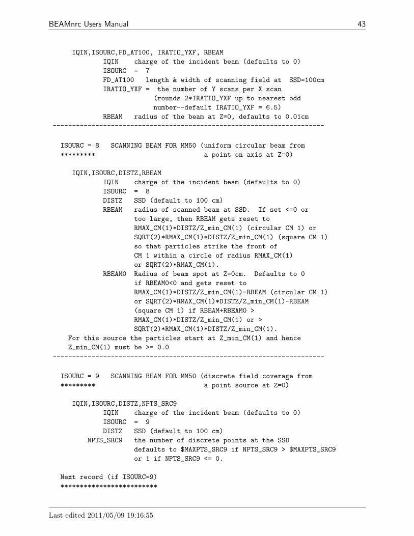
BEAMnrc Users Manual 43
IQIN,ISOURC,FD_AT100, IRATIO_YXF, RBEAMIQIN charge of the incident beam (defaults to 0)ISOURC = 7FD_AT100 length & width of scanning field at SSD=100cmIRATIO_YXF = the number of Y scans per X scan
(rounds 2*IRATIO_YXF up to nearest oddnumber--default IRATIO_YXF = 6.5)
RBEAM radius of the beam at Z=0, defaults to 0.01cm----------------------------------------------------------------------
ISOURC = 8 SCANNING BEAM FOR MM50 (uniform circular beam from********* a point on axis at Z=0)
IQIN,ISOURC,DISTZ,RBEAMIQIN charge of the incident beam (defaults to 0)ISOURC = 8DISTZ SSD (default to 100 cm)RBEAM radius of scanned beam at SSD. If set <=0 or
too large, then RBEAM gets reset toRMAX_CM(1)*DISTZ/Z_min_CM(1) (circular CM 1) orSQRT(2)*RMAX_CM(1)*DISTZ/Z_min_CM(1) (square CM 1)so that particles strike the front ofCM 1 within a circle of radius RMAX_CM(1)or SQRT(2)*RMAX_CM(1).
RBEAM0 Radius of beam spot at Z=0cm. Defaults to 0if RBEAM0<0 and gets reset toRMAX_CM(1)*DISTZ/Z_min_CM(1)-RBEAM (circular CM 1)or SQRT(2)*RMAX_CM(1)*DISTZ/Z_min_CM(1)-RBEAM(square CM 1) if RBEAM+RBEAM0 >RMAX_CM(1)*DISTZ/Z_min_CM(1) or >SQRT(2)*RMAX_CM(1)*DISTZ/Z_min_CM(1).
For this source the particles start at Z_min_CM(1) and henceZ_min_CM(1) must be >= 0.0
----------------------------------------------------------------------
ISOURC = 9 SCANNING BEAM FOR MM50 (discrete field coverage from********* a point source at Z=0)
IQIN,ISOURC,DISTZ,NPTS_SRC9IQIN charge of the incident beam (defaults to 0)ISOURC = 9DISTZ SSD (default to 100 cm)
NPTS_SRC9 the number of discrete points at the SSDdefaults to $MAXPTS_SRC9 if NPTS_SRC9 > $MAXPTS_SRC9or 1 if NPTS_SRC9 <= 0.
Next record (if ISOURC=9)*************************
Last edited 2011/05/09 19:16:55

44 NRCC Report PIRS-0509(A)revL
Repeat for I=1,NPTS_SRC9
X_SRC9(I),Y_SRC9(I),PROB_SRC9(I) (3F15.0)X_SRC9(I) X coordinate of point I at the SSD (cm)Y_SRC9(I) Y coordinate of point I at the SSD (cm)PROB_SRC9(I) probability of a particle being at point I
Note that PROB_SRC9(I) need not be normalized; they areautomatically normalized in the source routine.For this source the particles start at Z_min_CM(1) and henceZ_min_CM(1) must be >= 0.0
----------------------------------------------------------------------
ISOURC = 10 PARALLEL CIRCULAR BEAM INCIDENT FROM THE SIDE***********
(NOTE: beam facing X-AXIS, I.E., UINC should be < 0.0 )(this source should only be used together with CM XTUBE )(for simulating the target of an X-ray tube. )(XTUBE should always be the first CM in the geometry. )
IQIN,ISOURC,RBEAM,UINC,VINC,WINCIQIN charge of the incident beam (defaults to 0)ISOURC = 10RBEAM radius of parallel beam in cm (defaults to max radius)UINC incident X-axis direction cosine (UINC < 0.0)VINC incident Y-axis direction cosineWINC incident Z-axis direction cosine
Note: (UINC,VINC,WINC) get automatically normalizeddefaults to (-1.0,0.0,0.0)
---------------------------------------------------------------------
ISOURC = 13 PARALLEL RECTANGULAR BEAM INCIDENT FROM THE SIDE***********
(Note beam facing X-axis, i.e., UINC should be < 0.0 )(this source should only be used together with CM XTUBE )(for simulating the target of an X-ray tube. )(XTUBE should always be the first CM in the geometry. )
IQIN,ISOURC,YBEAM,ZBEAM,UINC,VINCIQIN charge of the incident beam (defaults to 0)ISOURC = 13YBEAM half-width of parallel beam in cm (defaults to 0.2 cm)ZBEAM half-height of parallel beam in cm (defaults to 0.2 cm)UINC incident X-axis direction cosine (UINC < 0.0)VINC incident Y-axis direction cosine
(incident Z-axis direction cosine WINC default to 0.0)Note: (UINC,VINC) get automatically normalized
defaults to (-1.0,0.0,0.0)------------------------------------------------------------------------
3 DESCRIPTION OF MAIN BEAMNRC INPUT FILE

BEAMnrc Users Manual 45
ISOURC = 15 NRC SWEPT BEAM WITH BEAM DIVERGENCE AND RADIAL INTENSITY*********** DISTRIBUTION
IQIN,ISOURC,GAMMA,ZFOCUS,RTHETAIN,THETAINIQIN charge of the incident beam (defaults to 0)ISOURC = 15GAMMA half angle of the cone swept by the beam (degrees)ZFOCUS Z position of the apex of the cone (cm)RETHETAIN radius at which THETAIN, the divergence angle of the
beam, is specified (cm). RTHETAIN must be > 0.THETAIN divergence angle of the beam (degrees). If GAMMA
is not 0, then THETAIN can be set to 0; otherwiseit must be > 0.
Note that particles are always incident at Z_min_CM(1), regardless ofthe value of ZFOCUS
Next record (If ISOURC=15)***********
SPCNAM FILENAME (with EXT) containing description of the radialintensity distribution of the incident particles
(maximum 80 characters)_______________________________________________________FILE FORMAT for SPCNAM:NRDIST(RDISTF(I),RPDF(I),I=1,NRDIST)
NRDIST # radial binsRDISTF(I) upper radius of bin I (cm)RPDF(I) probability of particle being in bin I.
------------------------------------------------------------------------
ISOURC = 19 PARALLEL ELLIPTICAL BEAM FROM FRONT GAUSSIAN IN X AND Y***********
IQIN,ISOURC,RBEAM,UINC,VINC,WINC,sigma_src19,RBEAMYIQIN charge of the incident beam (defaults to 0)ISOURC = 19RBEAM sigma of the 2-D gaussian distribution (RBEAM > 0)
in the X-direction in cmor
-FWHM of 2-D gaussian distribution (RBEAM < 0) inthe X-direction in cmNote: sigma of gaussian distribution is limited to
<RMAX_CM(1) for circular CM 1 and<SQRT(2)*RMAX_CM(1) for square CM 1
UINC incident x-axis direction cosineVINC incident y-axis direction cosineWINC incident z-axis direction cosine
Note: (UINC,VINC,WINC) get automatically normalized
Last edited 2011/05/09 19:16:55

46 NRCC Report PIRS-0509(A)revL
defaults to (0.0,0.0,1.0)sigma_src19 mean angular spread of particles about Z axis
in degrees (none if set <=0). Overrides incidentdirection cosines if set > 0, so that beam is assumedto be centred on Z axis.
RBEAMY same as RBEAM but for Y-direction. If set to 0,then RBEAMY=RBEAM for a circular beam.
------------------------------------------------------------------------
ISOURC = 21 FULL PHASE-SPACE SOURCE***********
IQIN,ISOURC,INIT_ICM,NRCYCL,IPARALLEL,PARNUM,ISRC_DBS,RSRC_DBS,SSDSRC_DBS,ZSRC_DBS
IQIN dummy NOT USED. Set = 9 for this source by BEAMnrcISOURC = 21INIT_ICM particles start at front surface of this CM
(INIT_ICM is actually read as a real)NRCYCL Number of times to recycle each particle in a phase
space source. Each particle in the phase spacefile is used a total of NRCYCL+1 times beforegoing on to the next particle.If NRCYCL is set <=0 then NRCYCL is automaticallycalculated to use the entire phase space file with norestarts. The calculated NRCYCL does not take intoaccount particles that are rejected because theymiss the geometry.If NRCYCL is set > 0, then the user-input value isused.If NCASE > no. of particles in the phase space file,then use of NRCYCL is essential for accuratestatistics. If you are unsure of how many times torecycle, use the automatically-calculated value ofNRCYCL. If this still results in many restarts(because of multiple passers being rejected and/orphotons rejected because they fall outside the DBSsplitting radius--see below)then re-run the simulation with NRCYCL set manuallyto:NCASE/(NNPHSP-NNPHSP*(NPASS_ph_sp+NFAT_ph_sp)/
(NTOT_ph_sp+NPASS_ph_sp+NFAT_ph_sp) ) -1where NNPHSP is the no. of particles in the file,NTOT_ph_sp is total no. of particles used (notincluding recycling), NPASS_ph_sp is total no.of multiple passers ignored (not includingrecycling), and NFAT_ph_sp is the no. of photonsrejected (not including recycling because they falloutside the DBS splitting radius at the SSD (onlyif ISRC_DBS=1--see below)). These numbers are
3 DESCRIPTION OF MAIN BEAMNRC INPUT FILE

BEAMnrc Users Manual 47
available in the .egslst file. Always round yourcalculated value of NRCYCL up.
IPARALLEL set >1 if you are distributing the job amongIPARALLEL machines. IPARALLEL is used with PARNUM(see below) to partition a phase space source intoIPARALLEL equal parts.
PARNUM For each of the IPARALLEL parallel jobs, PARNUMshould have a different integer value in the range1<=PARNUM<=IPARALLEL. The partition of the phasespace source that is used for a particular job isthen given by:
(PARNUM-1)*(NNPHSP/IPARALLEL)<INPHSP<=(PARNUM)*(NNPHSP/IPARALLEL)
where NNPHSP is the total number of particles in thephsp source and INPHSP is the particle no. chosen.
ISRC_DBS Set to 1 if you used directional bremsstrahlungsplitting (DBS) in the BEAM simulation used togenerate this phase space source and you wish toreject photons not aimed into the splittingfield(which are fat). These fat photons compromisestatistics. Set to 0 otherwise.
RSRC_DBS DBS splitting radius in BEAM simulation used togenerate this source (cm). Only used if ISRC_DBS=1.
SSDSRC_DBS SSD at which RSRC_DBS was defined in the BEAM sim.used to generate this source (cm). Only used ifISRC_DBS=1.
ZSRC_DBS Z where the phase space source was collected inthe BEAM simulation used to generate this source(cm).Only used if ISRC_DBS=1.
Photons are projected from ZSRC_DBS to SSDSRC_DBS and if they will falloutside of RSRC_DBS (based on their trajectory) then they willbe rejected. This prevents fat photons from compromising statistics.
Next record (If ISOURC=21)***********
SPCNAM FILENAME (with EXT) contains phase space information(maximum of 80 characters)
------------------------------------------------------------------------
ISOURC = 23 BEAM SIMULATION SOURCE***********
IQIN,ISOURC,INIT_ICM,ISRC_DBS,ALPHA24,BETA24,DIST24IQIN dummy NOT USED. Set = 9 for this source by BEAMnrcISOURC = 23INIT_ICM particles start at front surface of this CM
(INIT_ICM is actually read as a real)ISRC_DBS Set to 1 if you are using directional bremsstrahlung
Last edited 2011/05/09 19:16:55
48 NRCC Report PIRS-0509(A)revL
splitting (DBS) in the BEAM simulation sourceand you wish to reject fat photons (not aimed intothe splitting field). These fat photons compromisestatistics. Set to 0 otherwise.
ALPHA24 Angle of rotation of source plane about X-axisin degrees. Positive angle is clockwise rotation.(-90 < ALPHA24 < 90)
BETA24 Angle of rotation of source plane about Y-axisin degrees. Positive angle is counter-clockwiserotation. (-90 < ALPHA24 < 90)
DIST24 Distance of point of rotation above INIT_ICM.
Note restriction that if ALPHA24~=0 and/or BETA24 ~=0, then INIT_ICMmust be > 1. This is because the rotation will result in someparticles incident within INIT_ICM-1. Also, the following CMscurrently do not handle the general case of a forward-directed particleincident from within them:APPLICAT,ARCCHM,CHAMBER,CIRCAPP,CONESTAK,DYNJAWS,JAWS,MESH,PYRAMIDS,SIDETUBEThus, if ALPHA24~=0 and/or BETA24 ~=0 and INIT_ICM or INIT_ICM-1 isone of these, negative ustep errors may result.
Next record (If ISOURC=23)***********
the_beam_code, the_pegs_file, the_input_file (3A80)
the_beam_code The name of the BEAM code you are running as asource (ie BEAM_sourceaccelname). This must havebeen compiled as a shared library(libBEAM_accelname.so or BEAM_accelname.dll) andexist in EGS_HOME/bin/config.
the_pegs_file The pegs data set used by the BEAM simulation source(no .pegs4dat extension). This must be inHEN_HOUSE/pegs4/data or EGS_HOME/pegs4/data.
the_input_file The input file used to run the BEAM simulationsource (no .egsinp extension). This must exist inyour EGS_HOME/BEAM_sourceaccelname directory. Itmust be a working input file and must be set up towrite a phase space file at a single scoring plane.This plane becomes where particles are sampled fromfor the second-stage BEAMnrc simulation (no phasespace file is scored, however).
------------------------------------------------------------------------
ISOURC = 24 FULL PHASE-SPACE SOURCE INCIDENT FROM USER-DEFINED ANGLE***********
Inputs identical to ISOURC = 21 with the following additional line of
3 DESCRIPTION OF MAIN BEAMNRC INPUT FILE

BEAMnrc Users Manual 49
inputs after SPCNAM:
ALPHA24,BETA24,DIST24
ALPHA24 Angle of rotation of source plane about X-axisin degrees. Positive angle is clockwise rotation.(-90 < ALPHA24 < 90)
BETA24 Angle of rotation of source plane about Y-axisin degrees. Positive angle is counter-clockwiserotation. (-90 < ALPHA24 < 90)
DIST24 Distance of point of rotation above INIT_ICM.
Note restriction that if ALPHA24~=0 and/or BETA24 ~=0, then INIT_ICMmust be > 1. This is because the rotation will result in someparticles incident within INIT_ICM-1. Also, the following CMscurrently do not handle the general case of a forward-directed particleincident from within them:APPLICAT,ARCCHM,CHAMBER,CIRCAPP,CONESTAK,DYNJAWS,JAWS,MESH,PYRAMIDS,SIDETUBEThus, if ALPHA24~=0 and/or BETA24 ~=0 and INIT_ICM or INIT_ICM-1 isone of these, negative ustep errors may result.
The initial idea and much of the coding for Source 24 is courtesy ofPatrick Downes at University of Cardiff, Wales.
------------------------------------------------------------------------
ISOURC = 31 BEAM CHARACTERIZATION MODEL,************
IQIN,ISOURC,CMSOUIQIN charge of incident beam (not used)ISOURC = 31CMSOU particles start at the front surface of this CM
Next record (If ISOURC=31)***********
SPCNAM FILENAME (with EXT) contains information on beam model(maximum of 80 characters)
--------------------------------------------------------------------------
Next Record (IF ISOURC <21) SOURCE ENERGY INPUT*********** *******************
MONOEN (I8)= 0 if monoenergetic beam (the default)= 1 if energy spectrum to be used
Note: BEAMnrc sets MONOEN=2 for phase space inputs
Next Record (IF MONOEN = 0)***********
Last edited 2011/05/09 19:16:55
50 NRCC Report PIRS-0509(A)revL
EIN (F15.0)kinetic energy of the incident beam in MeV(defaults to 1.25), only for MONOEN=0
Next Record (IF MONOEN = 1)***********FILNAM(80A1) FILENAME(WITH EXT) contains spectrum information
which must be in NRC’s ensrcV format._______________________________________________________FILE FORMAT:SPEC_TITLE (A80)NENSRC,ENMIN,IMODE (I10,F15.0,I5)(ENSRCD(IB),SRCPDF(IB),IB=1,NENSRC) (2F20.0)
NENSRC # Energy bins in spectrum histogramENMIN Lower energy of first binIMODE =0 assuming counts/bin, =1 counts/MeVENSRCD(I),SRCPDF(I) I=1,NENSRC
Top of energy bin and probability ofinitial particle being in this bin.Probability does not need to be normalized
_______________________________________________________
Next Record (IF MONOEN = 1)***********IOUTSP (I5):
= 0 no spectrum data in output summary= 1 include spectrum data in output summary
---------------------------------------------------------------------------
TRANSPORT CONTROL INPUT***********************
Next Record***********ESTEPIN,SMAX,ECUTIN,PCUTIN,IDORAY,IREJCT_GLOBAL,ESAVE_GLOBAL,IFLUOR
ESTEPIN Dummy variable (used to be ESTEPE -- max. fractionalenergy loss/electron step)
SMAX Dummy variable (used to be SMAX -- max. step length)ECUTIN electron cut off in MeV - total energy
If this is > ECUT as input in the EGSnrc input section(see below), then ECUT is set to ECUTIN. Defaultvalue for ECUT is AE.
PCUTIN photon cut off in MeV. If this is > PCUT as inputin the EGSnrc input section (see below), then PCUTis set to PCUTIN. Default value for PCUT is AP.
IDORAY Dummy variable (used to turn Rayleigh scattering on/off)IREJCT_GLOBAL = 0 no electron range rejection
= 1 do electron range rejection--if residual
3 DESCRIPTION OF MAIN BEAMNRC INPUT FILE

BEAMnrc Users Manual 51
range to ECUTRR(IRL) is < DNEAR andelectron energy is < ESAVE_GLOBAL, terminatehistory. ECUTRR(IRL) may vary from componentmodule to component module and is calculated basedon the particle making it to the bottom of theaccelerator with energy > ECUT
= 2 as in =1, but use a non-calculated ECUTRR = ECUT(IRL)this should be used if interested in morethan phase-space data at base of simulation
=-1,-2 Same as above, but now Russian Roulette is playedwith ALL electrons that can not escape the regionand are not fat. Only applicable with DBS.
ESAVE_GLOBAL energy below which an electron will be discardedIf E<ESAVE_GLOBAL & the electron cannot escape from thecurrent region with E>ECUTRR(IRL). This ignores bremlosses.
IFLUOR Dummy variable (used to turn X-ray fluorescence on/off)
The dummy inputs are retained for compatibility with EGS4/BEAM inputfiles.
----------------------------------------------------------------------------
Next Record Photon Forcing Controls*********** ***********************
IFORCE,NFMIN,NFMAX,NFCMIN,NFCMAXIFORCE = 0 normal photon transport (the default)
= 1 force photon interaction in the geometryNFMIN number of photon interaction/history at which to start
photon-interaction-forcing (defaults to 1)--thisoption has been deleted and NFMIN is now always treatedas 1.
NFMAX number of photon interaction/history after which tostop forcing photon to interact (defaults to 1)
NFCMIN number of CM to start photon interaction forcing( default to 1 )
NFCMAX number of last CM in which photons forced to interact( default to max_cms )If a particle passes thru NFCMIN to NFCMAX, it isforced to interact there for the first NFMAXinteractions. The WEIGHTof this photon is reduced and the remaining WEIGHT iscarried by another photon which will be transported
----------------------------------------------------------------------------
Next record SCORING PLANE INPUT*********** *******************
NSC_PLANES, (IPLANE_to_CM(I), I=1,NSC_PLANES)
Last edited 2011/05/09 19:16:55
52 NRCC Report PIRS-0509(A)revL
NSC_PLANES number of scoring planes >=0IPLANE_to_CM CM numbers corresponding to the scoring planes
fluence is scored at the back of a component modulephase space data written from same planes
(Note only IPLANE_to_CM(1) is used for beam model analysis);
Next record SCORING ZONE TYPE/DIMENSIONS*********** ****************************
Repeat the next pair of lines for ISCORE=1,...,NSC_PLANES
NSC_ZONES(ISCORE), MZONE_TYPE(ISCORE)NSC_ZONES number of scoring zones within each scoring plane
(= 0: maximum number available with equal zone area)MZONE_TYPE 0 annular zones (default)
1 square (ring) zones2 grid
Next record (for NSC_ZONES(ISCORE)>0 and MZONE_TYPE = 0 or 1)***********
(RSCORE_ZONE(ISCORE,I), I=1,NSC_ZONES) (up to 10/line)RSCORE_ZONE outer radius of each scoring zone in order of
increasing radius (MZONE_TYPE = 0)half width from origin of each scoring zone
in order of increasing width (MZONE_TYPE = 1)
Next record (for NSC_ZONES(ISCORE)>0 and MZONE_TYPE = 2)***********
XMIN_ZONE, XMAX_ZONE, YMIN_ZONE, YMAX_ZONE, NX_ZONE, NY_ZONEXMIN_ZONE lower x bound of grid area (cm)XMAX_ZONE upper x bound of grid area (cm)YMIN_ZONE lower y bound of grid area (cm)YMAX_ZONE upper y bound of grid area (cm)NX_ZONE number of grid zones in x directionNY_ZONE number of grid zones in y direction
----------------------------------------------------------------------------
Next record DOSE COMPONENTS CALCULATION INPUT*********** *********************************
ITDOSE_ONITDOSE_ON = 0 (DEFAULT) only total dose is calculated
= 1 total dose and dose components may be calculated
There are 2 classes of components. First is selected as dose fromparticles or descendents of particular charge as they cross aspecified boundary. Second is based on bit selections in thevariable LATCH, either inclusive or exclusive sets - i.e. dependson where particle has been or interacted.
3 DESCRIPTION OF MAIN BEAMNRC INPUT FILE

BEAMnrc Users Manual 53
Next record (if ITDOSE_ON=1)***********
ICM_CONTAM, IQ_CONTAM (2I5)All particles of type IQ_CONTAM (0=photons, 1=chargedparticles) are identified as contaminants when they enterthe front of CM number ICM_CONTAM and their dose is scored ascontaminant dose in all dose zones.If ICM_CONTAM = 0, no contaminant dose is scored.LATCH_OPTION = 1 is not allowed with ICM_CONTAM non-zero
Next record (if ITDOSE_ON=1)***********
LNEXC (I5)LNEXC: # of dose components scored which exclude dose from
particles with certain LATCH bits set - i.e. which havenot been in certain regions.LNEXC = 0 is allowed. LNEXC <= $MAXIT - 3
Next records (if LNEXC > 0)************
(L_N_EXC(I,J), J=1, 31 ) (31I5) (repeat LNEXC times, line by line)L_N_EXC(I,J): Bit #s in LATCH for dose component I
(will exclude dose from component I if these bits set)
Next record (if ITDOSE_ON=1)***********
LNINC (I5)LNINC: # of dose components scored for particles
from specified regions (with designated bit settingsin LATCH). LNINC <= $MAXIT - LNEXC - 3
Next records (if LNINC > 0)************
(L_N_INC(I,J), J=1, 31 ) (31I5) (repeat LNINC times, line by line)L_N_INC(I,J): Bit #s in LATCH for dose component I.
These are in two groups/line, separated by a zero.Of the first group of bits, at least one mustbe set to be in this dose component.The second group need not be present, but ifit is, none of these bits can be set to be inthis dose component.
---------------------------------------------------------------------------
Next record INPUT FRONT SURFACE (Z) FOR CM 1*********** ********************************
Z_min_CM(1) Z-coordinate of front surface for component module 1
Last edited 2011/05/09 19:16:55
54 NRCC Report PIRS-0509(A)revL
This includes any air gap and defines front of model.A common value will be 0.0 except for sources 8 & 9.For most sources except for ISOURC=3, 21 & 31, this isalso the source plane on which the particles are incident
Note that the front of all CMs is given w.r.t. z = 0.0, notw.r.t. Z_min_CM(1).
Next record Blank or dummy line indicating start of*********** input for component modules
Next records (many) COMPONENT MODULE INPUT************* **********************
Component module parameters are input in order of their appearance in thecode, that is, in the order they occur in $CM_LIST. See the ’INPUT FROMUNIT 5’ section in each CM subroutine for the list of input parameters.
There are two lines before the input of parameters for each CM:one is *********************************************** ,the other is RMAX_CM, the outer boundary(radius or 1/2 of square) of CM
---------------------------------------------------------------------------
EGSnrc INPUTS*************
(modified from the description in $HEN_HOUSE/src/get_inputs.mortran)
The input for parameters associated with EGSnrc follows a formatused by all the standard EGSnrc user codes. The rest of the BEAMnrcinput has not been changed because the GUI’s make the details of theformat irrelevant.
All input associated with selection of EGSnrc transport parametersis not crucial for the execution as there are default values set.Therefore, if some of the input options in this section aremissing/misspelled, this will be ignored and defualt parameter assumedAs the transport parameter input routine uses get_inputs, a lotof error/warning messages may be produced on UNIT 15, though.If you don’t have the intention of changing default settings,simply ignore the error messages.
The delimeters are:start mc transport parameter::stop mc transport parameter:
Currently, the following options are available (case does not matter andthe internal variables are shown in [ ] brackets):
3 DESCRIPTION OF MAIN BEAMNRC INPUT FILE

BEAMnrc Users Manual 55
Global ECUT= Global (in all regions) electron transport cutoff energy (in MeV). If this imput is missing,or is < ECUTIN from the main BEAMnrc inputs(See above) then ECUTIN is used for Global ECUT.Global ECUT defaults to AE(medium).[ ECUT ]
Global PCUT= Global (in all regions) photon transport cutoff energy (in MeV). If this imput is missing,or is < PCUTIN from the main BEAMnrc inputs(See above) then PCUTIN is used for Global PCUT.Global PCUT defaults to AP(medium).[ PCUT ]
Global SMAX= Global (in all regions) maximum step-sizerestriction for electron transport (in cm).No SMAX restriction is necessary if the electronstep algorithm is PRESTA-II and the EXACT boundarycrossing algorithm (the default) is used. In thiscase, SMAX will default to 1e10. However, if eitherElectron-step algorithm= PRESTA-IorBoundary crossing algorithm= PRESTA-I,
then a step-size restriction is necessary, andSMAX will default to 5 cm.[ SMAXIR ]
ESTEPE= Maximum fractional energy loss per step.Note that this is a global option only, noregion-by-region setting is possible. If missing,the defualt is 0.25 (25%).[ ESTEPE ]
XImax= Maximum first elastic scattering moment per step.Default is 0.5, NEVER use value greater than 1 asthis is beyond the range of MS data available.[ XIMAX ]
Boundary crossing algorithm=There are two selections possible: EXACT andPRESTA-I. PRESTA-I means that boundaries willbe crossed a la PRESTA. That is, with lateralcorrelations turned off at a distance given by‘Skin depth for BCA’ (see below) from the boundaryand MS forced at the boundary. EXACT meansthe algorithm will cross boundaries in a singlescattering (SS) mode, the distance from a boundaryat which the transition to SS mode is made isdetermined by ‘Skin depth for BCA’ (see below).Default is EXACT since PRESTA-I may result insignificant dose overestimates when CHAMBER isused as a phantom, and EXACT will not significantlyincrease CPU time in most accelerators.
Last edited 2011/05/09 19:16:55

56 NRCC Report PIRS-0509(A)revL
[ bca_algorithm, exact_bca ]Skin depth for BCA=
If Boundary crossing algorithm= PRESTA-Ithen this is the distance from the boundary (inelastic MFP) at which lateral correlations will beswitched off. The default in this case is tocalculate a value based on the scattering power atECUT (same as PRESTA with EGS4). IfBoundary crossing algorithm= EXACT (default) thenthis is the distance from the boundary (in elasticMFP) at which the algorithm will go into singlescattering mode and defaults to 3 mfp.Note that if you choose EXACT boundary crossing andset Skin depth for BCA to a very large number (e.g.1e10), the entire calculation will be in SS mode.If you choose PRESTA-I boundary crossing and makeSkin depth for BCA large, you will get default EGS4behaviour (no PRESTA).[ skindepth_for_bca ]
The new transport mechanics of EGSnrc are maintained away fromboundaries.
Electron-step algorithm=PRESTA-II (the default), the name isused for historical reasonsor PRESTA-IDetermines the algorithm used to take into accountlateral and longitudinal correlations in acondensed history step.[ transport_algorithm ]
Spin effects= Off, On, (default is On)Turns off/on spin effects for electron elasticscattering. Spin On is ABSOLUTELY necessary forgood backscattering calculations. Will make adifference even in ‘well conditioned’ situations(e.g. depth dose curves for RTP energy rangeelectrons).[ spin_effects ]
Brems angular sampling= Simple, KM, (default is Simple)If Simple, use only the leading term of the Koch-Motzdistribution to determine the emission angle ofbremsstrahlung photons. If KM, completemodified Koch-Motz 2BS is used (modificationsconcern proper handling of kinematics at lowenergies, makes 2BS almost the same as 2BN at lowenergies).[ IBRDST ]
Brems cross sections= BH, NIST, NRC, default is BH
3 DESCRIPTION OF MAIN BEAMNRC INPUT FILE

BEAMnrc Users Manual 57
If BH is selected, the Bethe-Heitler bremsstrahlungcross sections (Coulomb corrected above 50 MeV)will be used. If NIST is selected, the NIST bremscross section data base (which is the basis forthe ICRU radiative stopping powers) will be employed.Differences are negligible for E > ,say, 10 MeV,but signifficant in the keV energy range. If NRC isselected, NIST data including corrections forelectron-electron brems will be used (typically onlysignificant for low values of the atomic number Zand for k/T < 0.005).
Bound Compton scattering= On, Off or Norej (Default is Off)If Off, Compton scattering will be treated withKlein-Nishina, with On Compton scattering istreated in the Impulse approximation.Make sure to turn on for low energy applications,not necessary above, say, 1 MeV. Option Norejuses full bound Compton cross section datasupplied in input below and does not rejectinteractions.[ IBCMP ]
Compton cross sections= Bound Compton cross-section data. User-supplied bound Compton cross-sections in the file$HEN_HOUSE/data/comp_xsections_compton.data, wherecomp_xsections is the name supplied for this input.This is only used if Bound Compton scattering= Simpleand is not available on a region-by-region basis(see below). The default file (ie in the absenceof any user-supplied data) is compton_sigma.data.[ comp_xsections ]
Radiative Compton corrections= On or Off (default). If on, theninclude radiative corrections for Compton scattering.Equations are based on original Brown & Feynmanequations (Phys. Rev. 85, p 231--1952). Requiresa change to the user codes Makefile to include$(EGS_SOURCEDIR)rad_compton1.mortran in theSOURCES (just before $(EGS_SOURCEDIR)egsnrc.mortran).[ radc_flag ]
Pair angular sampling= Off, Simple or KM (Default is Simple)If off, pairs are set in motion at an angle m/Erelative to the photon direction (m is electron restenergy, E the photon energy). Simple turns onthe leading term of the angular distribution(this is sufficient for most applications),KM (comes from Koch and Motz) turns on using 2BSfrom the article by Koch and Motz.Always use Simple or KM.[ IPRDST ]
Last edited 2011/05/09 19:16:55

58 NRCC Report PIRS-0509(A)revL
Pair cross sections= BH (default) or NRC. If set to BH, then useBethe-Heitler pair production cross-sections. If setto NRC, then use NRC pair production cross-sections(in file $HEN_HOUSE/data/pair_nrc1.data). Onlyof interest at low energies, where the NRC cross-sections take into account the assymmetry in thepositron-electron energy distribution.[ pair_nrc ]
Photoelectron angular sampling= Off or On (Default is Off)If Off, photo-electrons get the direction of the‘mother’ photon, with On, Sauter’s furmula isused (which is, striktly speaking, valid only forK-shell photo-absorption).If the user has a better approach, replace the macro
$SELECT-PHOTOELECTRON-DIRECTION;The only application thatOnly situation encountered where this made asmall difference was a big ion chamber (cavity sizecomparable with electron range) with high-Z wallsin a low energy photon beam.[ IPHTER ]
Rayleigh scattering= Off, On, customIf On, turned on coherent (Rayleigh) scattering.Default is Off. Should be turned on for low energyapplications. Not set to On by default becauseOn requires a special PEGS4 data set. If set tocustom, then media for which custom form factorsare to be specified are listed in the input:ff media names=and the corresponding files containing custom dataare listed in:ff file names=[ IRAYLR ]
Atomic relaxations= Off, On (Default is Off)The effect of using On is twofold:- In photo-electric absorption events, the element(if material is mixture) and the shell the photonis interacting with are sampled from theappropriate cross seections
- Shell vacancies created in photo-absorption eventsare relaxed via emission of fluorescent X-Rays,Auger and Koster-Cronig electrons.Make sure to turn this option on for low energyapplications.[ IEDGFL ]
Electron impact ionization= Off, On, Casnati, Kolbenstvedt, Gryzinski(Default is Off)
Determines which, if any, theory is used to model
3 DESCRIPTION OF MAIN BEAMNRC INPUT FILE

BEAMnrc Users Manual 59
electron impact ionization. If set to ’On’ then thetheory of Kawrakow is used. Other settings use thetheory associated with the name given. See futureeditions of the EGSnrc Manual (PIRS-701) for moredetails. This is only of interest in keV X-Raysimulations. Otherwise, leave it Off.[ eii_flag ]
Photon cross sections= epdl,xcom,custom (Default is Storm-Israelcross-sections from PEGS4)The name of the cross-section data for photoninteractions. This input line must be left outto access the default Storm-Israel cross-sectionsfrom PEGS4. ’edpl’ uses cross-sections from theevaluated photon data library (EPDL) from LawrenceLivermore. ’xcom’ will use the XCOM cross-sectionsfrom Burger and Hubbell. The user also has theoption of using their own customized cross-sectiondata. See the BEAMnrc manual for more details.[ photon_xsections ]
Photon cross-sections output= Off (default) or On. If On, thena file $EGS_HOME/user_code/inputfile.xsections isoutput containing photon cross-section data used.[ xsec_out ]
Atomic relaxations, Rayleigh scattering, Photoelectron angularsampling and Bound Compton scattering can also be turned On/Offon a region-by-region basis. To do so, put e.g.Atomic relaxations= On in Regions orAtomic relaxations= Off in regions
in your input file. Then use the relevant one of:Relaxations start region=Relaxations stop region=
orBound Compton start region=Bound Compton stop region=
orRayleigh start region=Rayleigh stop region=
orPE sampling start region=PE sampling stop region=
each followed by a list of one or morestart and stop regions separated by commas.
Example:Atomic relaxations= On in RegionsRelaxations start region= 1, 40Relaxations stop region= 10, 99
will first turn off relaxations everywhere and
Last edited 2011/05/09 19:16:55

60 NRCC Report PIRS-0509(A)revL
then turn on in regions 1-10 and 40-99.Note that input is checked against min. and max.region number and ignored ifstart region < 1 or stop_region > $MXREG orstart region > stop region.
---------------------------------------------------------------------------
Rejection Plane Inputs**********************
Used to define a rejection plane for use in conjunction with directionalbremsstrahlung splitting (DBS, IBRSPL=2, see above).Inputs can exist without IBRSPL=2, but they will not be used.
Inputs must appear between the delimiters::Start DBS rejection plane::Stop DBS rejection plane:
Inputs are:
Use a rejection plane= Off, On (default is Off)Set to On if you want to define a rejectionplane.[USE_REJPLN]
Z(cm) from zero reference plane= Z position of reference plane.[Z_REJPLN]
Fat photons and electrons will be discarded if they are aboutto interact at Z>=Z_REJPLN. Used to prevent correlated particlesfrom being created close to a scoring plane, compromisingstatistics.
---------------------------------------------------------------------------
Bremsstrahlung Cross Section Enhancement (BCSE) Inputs******************************************************
Inputs for the BCSE variance reduction technique.
Inputs must appear between delimiters::Start BCSE::Stop BCSE:
Inputs are:
Use BCSE= Off, On (default is Off)Set to On to use BCSE.
3 DESCRIPTION OF MAIN BEAMNRC INPUT FILE

BEAMnrc Users Manual 61
[USE_BCSE]Media to enhance= A list of media in
which to enhance the bremsstrahlung cross-section. Ifnone of the media is found in the accelerator, then noBCSE is done.[is_bcse_medium]
Enhancement constant= Floating point factor by which bremsstrahlungcross-sections are enhanced. Typical values are in the range20 (megavoltage accelerators) -- 500 (x-ray tubes inmammography energy range).[BCSE_FACTOR_C]
Enhancement power= Floating point number that us used for an energydependent BCSE. If this input is <=0, then a constantBCSE factor is used that is given by BCSE_FACTOR_C. But ifthis input is >0, then the BCSE factor is computed on-th-flyusing 1 + BCSE_FACTOR_C*(E(np)-rm)**BCSE_POWER_N.Typical values for BCSE_POWER_N are 2...4. Note thatBCSE_FACTOR_C must be adjusted accordingly so that the aboveequations gives a factor of 20 (megavoltage accelerators) --500 (low energy x-ray tubes) for the maximum energy of theincident electron spectrum.If in doubt, just set to <=0 because the gain from anenergy dependent BCSE is modest (~20%).
Note that if BCSE is used in conjunction with uniform bremsstrahlungsplitting (UBS) or selective bremsstrahlung splitting (SBS), thenRussian Roulette is automatically turned on (IRRLTT=2--see above).
BCSE is most efficient when used in conjunction with DBS or UBS
---------------------------------------------------------------------------
CUSTOMIZED USER INPUTS**********************
This section contains inputs that are unique to the user. In generalthe user must modify beamnrc.mortran to read these inputs from the.egsinp file. Also, the GUI will not give access to these inputs.If no custom inputs are required, then this section can be omittedentirely.
Custom user inputs must appear in the .egsinp file between the delimiters::Start user inputs::Stop user inputs:
This section can appear either just before or just after the EGSnrcinputs (see above).
Last edited 2011/05/09 19:16:55
62 NRCC Report PIRS-0509(A)revL
Currently, the only custom user input hard-coded in beamnrc.mortranis:
PHSP OUTPUT DIRECTORY= /full directory path to where phase space filesare to be output, or blank
This allows the user to specify a directory other than$EGS_HOME/BEAM_accelname in which to write phase space data.Useful if phase space files are large and, due to disk spacelimitations, must be written to a /temp area. If left blankor omitted entirely, then phase space files are output to thedefault $EGS_HOME/BEAM_accelname directory.[ PHSP_OUTDIR ]
*****************************************************************************
3.1 Sample input files
Complete input files for simulation of a 10 MeV electron beam and a 16 MV photon beamcan be found in the appropriate subdirectories of:$OMEGA_HOME/beamnrc/BEAMnrc_examples in files EX10MeVe.egsinp and EX16MVp.egsinp
respectively. The file EXphantom.egsinp gives an example of using BEAMnrc to do anefficient depth-dose calculation (but only for the central axis). These examples are describedin separate reports[21, 22, 23] which are somewhat dated since one should now use the GUIsto run these examples.
The auxiliary script test_BEAMnrc (found on $HEN HOUSE/scripts) automatically createthe needed subdirectories on the user’s area (BEAM EX10MeVe etc.) and copy the relevant filesto them so that the user may execute BEAMnrc immediately (but the script only works onLinux/Unix and there is no corresponding replacement for Windows).
3 DESCRIPTION OF MAIN BEAMNRC INPUT FILE 3.1 Sample input files

BEAMnrc Users Manual 63
4 Source Routines
In general, the incident particles move in the direction of the z-axis. With the exceptionof ISOURC=3 (internal isotropic source), =10 and 13 (x-ray tube sources) or =21 and31 (phase space inputs), the particles start being transported on the Z_min_CM(1) plane.Conceptually, some of them originate at a point outside the accelerator model and areessentially transported through vacuum to the accelerator which starts at the Z_min_CM(1)
plane.
One of the major features of BEAMnrc is that a phase space file can be used as a sourcefile between any two CMs in the accelerator. By writing a suitable off-line routine to generatethe appropriate phase space file (use the macros in phsp macros.mortran), virtually anysource can be simulated. This feature also allows the accelerator simulation to be brokenup into components. For example, one might simulate the fixed components at the top ofan accelerator and then feed the phase space file into a variety of calculations with differentjaw or applicator settings.
For historic and compatibility reasons, the input to specify the source type and the chargeof the incident beam are on a single line (as outlined in section 3). In particular, note that thefirst variable is the charge, IQIN, or a dummy in those cases where the charge is determinedelsewhere (eg. for a phase space file input).
The following subsections describe the source routines available in BEAMnrc.
ISOURC=0 Parallel Circular Beam
ISOURC=1 Isotropic Point Source on Z-axis
ISOURC=3 Interior Isotropic Cylindrical Source
ISOURC=5 NRC Swept Beam
ISOURC=6 Parallel Rectangular Beam
ISOURC=7 Scanning Beam (sawtooth)
ISOURC=8 Scanning Point Source for MM50
ISOURC=9 Discrete Point Source for MM50
ISOURC=10 Parallel Circular Beam Incident from Side
ISOURC=13 Parallel Rectangular Beam Incident from Side
ISOURC=15 NRC Swept Beam with Radial Intensity Distribution and Radial Divergence
ISOURC=19 Elliptical Beam with Gaussian Distributions in X and Y, Parallel or withRadial Divergence
ISOURC=21 Phase Space Source
ISOURC=23 BEAMnrc Simulation Source
Last edited 2011/05/09 19:16:55

64 NRCC Report PIRS-0509(A)revL
ISOURC=24 Phase Space Source Incident from User-specified Angle
ISOURC=31 Beam characterization Model
4.1 ISOURC=0: Parallel Circular Beam
IQIN, 0, RBEAM, UINC, VINC, WINC
The parallel circular beam is always assumed to be incident on the center of the front ofthe first CM (i.e. at Z_min_CM(1)). The input parameters are:
IQIN The charge of the incident beam (defaults to 0=photons)
RBEAM Radius of the beam in cm (maximum is RMAX_CM(1) for a circular first CM or√2RMAX_CM(1) for a square first CM, it defaults to maximum if set > maximum)
UINC X-axis direction cosine (defaults to 0)
VINC Y-axis direction cosine (defaults to 0)
WINC Z-axis direction cosine (defaults to 1, i.e. parallel to the z-axis)
UINC, VINC, and WINC are automatically normalized by (UINC2+VINC2+WINC2). Notethat it is possible to have RBEAM = 0; this is a pencil beam. Figure 6 below shows the parallelcircular beam and its input parameters.
Z
X
Y
UINC
VINC
WINC
RBEAM
beamaxis
Z_min_CM(1)
Figure 6: Parallel Circular Beam (ISOURC=0) showing the beam radius, RBEAM, and thedirection cosines, UINC, VINC and WINC. Note that RBEAM is measured perpendicular tothe beam central axis. The beam axis always intersects Z min CM(1) at (X=0,Y=0).
4 SOURCE ROUTINES 4.1 ISOURC=0: Parallel Circular Beam

BEAMnrc Users Manual 65
4.2 ISOURC=1: Isotropic Point Source on Z-axis
IQIN, 1, DISTZ, RBEAM, GAMMA, XINL, XINU, YINL, YINU
The isotropic point source is placed on the Z-axis. It is assumed to be incident on thefirst CM, but can be placed any distance above Z_min_CM(1). The beam field can be circularor rectangular (see below). The circular beam is centred on the Z axis, while the rectangularbeam can be placed anywhere on the top surface of CM 1.
DISTZ Distance of the source above Z_min_CM(1) in cm (defaults to 100 cm)
RBEAM Radius of circular field at Z_min_CM(1) (if > 0). If RBEAM=0, then GAMMA (seebelow) is used to define the circular field. If RBEAM<0, then XINL, XINU, YINL, YINU (seebelow) are used to define a rectangular field. Maximum value of RBEAM is RMAX_CM(1)(circular CM 1) or
√2RMAX_CM(1) (square CM 1). RBEAM defaults to maximum if it is
set > maximum or if RBEAM=0.0 and GAMMA = 0.0.
GAMMA Half-angle of circular field at Z_min_CM(1) relative to the point source (Notethat this is simply another way of specifying the radius of a circular field, and is onlyused if RBEAM = 0.0; defaults to give maximum radius [see description of RBEAM above]if it is set so that the radius would be > maximum).
XINL, XINU, YINL, YINU Min. X, Max. X, Min. Y, Max Y dimensions of rect-angular field (only used if RBEAM<0) in cm. The rectangular field is restricted to -RMAX_CM(1)≤X≤RMAX_CM(1) and -RMAX_CM(1)≤Y≤RMAX_CM(1). The dimensions canbe set to give a line or point “field” anywhere on the top of CM 1.
DISTZ, between the source and Z_min_CM(1) is assumed to be a vacuum. Figure 7 belowillustrates the point source and its input variables.
X
Y
RBEAM
GAMMADISTZ
Z_min_CM(1)
Z
Figure 7: Point source (ISOURC=1) showing the distance of the source above Z min CM(1),specified by DISTZ, and the two different ways of specifying a circular field at Z min CM(1),RBEAM and GAMMA. A rectangular beam anywhere on the top surface of CM 1 can be specifiedby setting RBEAM<0 and using XINL, XINU, YINL, YINU to define the beam.
Last edited 2011/05/09 19:16:55 4.2 ISOURC=1: Isotropic Point Source on Z-axis

66 NRCC Report PIRS-0509(A)revL
4.3 ISOURC=3: Interior Isotropic Cylindrical Source
IQIN, 3, RMINBM, RBEAM, ZSMIN, ZSMAX
The uniform radiating cylindrical isotropic source can be a ring centred on the Z-axis ora cylinder with its central axis parallel to the X-axis. The orientation is controlled by thesign of the input variable, RBEAM (see below). The source is contained within the geometryof one or more component modules (i.e. it is able to span adjacent CMs). Currently, thissource can only be used inside CONESTAK, SIDETUBE or FLATFILT CMs because of the needto identify the initial regions. The input parameters for this source are:
RMINBM Inner radius of vertical ring (if RBEAM ≥ 0)or Z position of centre of horizontalcylinder (if RBEAM < 0)
RBEAM Outer radius of vertical ring (if ≥ 0)or negative radius of horizontal cylinder (if <0) (for vertical ring, maximum value is RMAX_CM of largest CM containing the source;for horizontal cylinder, maximum value keeps the radius entirely contained betweenZ_min_CM(1) and the bottom of the geometry; defaults to maximum if absolute valueis > maximum)
ZSMIN Z of top of vertical ring (if RBEAM ≥ 0)or minimum X of horizontal cylinder (ifRBEAM < 0) (for vertical ring, minimum value is Z_min_CM(1); for horizontal cylinder,minimum is -RMAX_CM of largest CM containing source; defaults to minimum if set <minimum)
ZSMAX Z of bottom of vertical ring (if RBEAM ≥ 0) or maximum X of horizontal cylinder (ifRBEAM < 0) in cm (for vertical ring, maximum is the bottom of geometry; for horizontalcylinder, maximum is RMAX_CM of largest CM containing source; defaults to maximumif set > maximum)
X
Y
Z
Z
ZSMIN
ZSMAX
RMINBM RBEAM
X
Y
Z
ZSMIN
Z
ZSMAX
−RBEAM
Z_min_CM(J)
Z_min_CM(J+1)
VERTICAL RING HORIZONTAL CYLINDER
RMINBM
Figure 8: Uniform isotropic radiating source (ISOURC=3) which is interior to the acceleratormodel. For vertical ring configuration shown on the left, set RBEAM ≥ 0. For horizontalcylinder configuration on right set RBEAM < 0. The meaning of the input variables dependson the configuration. The source is shown within a single CM, however it can span anynumber of adjacent CMs.
4 SOURCE ROUTINES 4.3 ISOURC=3: Interior Isotropic Cylindrical Source

BEAMnrc Users Manual 67
4.4 ISOURC=5: NRC Swept BEAM
IQIN, 5, GAMMA, RBEAM
The NRC swept beam is a parallel circular beam swept around the outside of an imaginarycone. The beam is assumed incident on the front of CM 1. The apex of the imaginary coneis always at (X=0,Y=0,Z=Z_min_CM(1)), and the cone angle is variable. Input parametersfor this source are:
IQIN Charge of the incident beam (defaults to 0 = photons)
GAMMA Half-angle of the cone in degrees (0o ≤ GAMMA < 90o)
RBEAM Radius of the beam in cm (maximum value RMAX_CM(1) if the first CM is circularor√
2RMAX_CM(1) if the first CM is square, defaults to maximum if set > maximum)
Figure 9 below shows the swept beam source and its input parameters.
Z
Y
X
RBEAM
GAMMA
beamaxis
Z_min_CM(1)
Figure 9: NRC swept beam source (ISOURC=5) showing the incident beam, with radiusRBEAM, sweeping the surface of an imaginary cone with apex half-angle GAMMA. Note that itis the beam axis which actually sweeps the surface of the cone.
Last edited 2011/05/09 19:16:55 4.4 ISOURC=5: NRC Swept BEAM

68 NRCC Report PIRS-0509(A)revL
4.5 ISOURC=6: Parallel Rectangular Beam
IQIN, 6, XBEAM0, YBEAM0, XBEAM, YBEAM
The parallel rectangular beam is the rectangular equivalent of the parallel circular beam(ISOURC=0) with the exception that the beam cannot be oblique, it is always perpendicularto the front surface of the first CM and this beam can be offset from the Z-axis. Inputparameters for the parallel rectangular beam are:
IQIN Charge of beam (defaults to 0 = photons)
XBEAM0 X position of beam centre in cm (defaults to 0 if XBEAM02 + YBEAM02 > RMAX_CM(1)2
when the first CM is circular or if |XBEAM0| or |YBEAM0| > RMAX_CM(1) when the firstCM is a square)
YBEAM0 Y position of beam centre in cm (defaults to 0 under same conditions as XBEAM0)
XBEAM Half-width of beam in X-direction in cm (defaults to keep |XBEAM0| + |XBEAM| ≤RMAX_CM(1))
YBEAM Half-width of beam in Y-direction in cm (defaults to keep |YBEAM0| + |YBEAM| ≤RMAX_CM(1)
Z
Y
X
beamaxis
XBEAM
YBEAM
(XBEAM0,YBEAM0)
Z_min_CM(1)
Figure 10: Parallel rectangular beam (ISOURC=6) showing the beam centre(XBEAM0,YBEAM0) and the X and Y half-widths (XBEAM,YBEAM).
4 SOURCE ROUTINES 4.5 ISOURC=6: Parallel Rectangular Beam

BEAMnrc Users Manual 69
4.6 ISOURC=7: Scanning Sawtooth Beam
IQIN, 7, FD AT100, IRATIO YXF, RBEAM
In the scanning sawtooth beam source, a circular parallel beam, incident on the front ofthe first CM, is scanned in a zig-zag pattern on the X-Y plane. The angle for the scan isselected as the particles leave the Z_min_CM(1) plane. This is an approximation of the realcase where the beam is bent below this point usually. The source randomly selects points inthe scan. The input parameters are:
IQIN Charge of the incident beam (defaults to 0 = photons)
FD AT100 Scanning field size at SSD=100cm in cm (field is FD AT100 x FD AT100). Thisis often much greater than the actual field size.
IRATIO YXF The number of Y scans per X scan (defaults to 6.5 if set ≤ 0; also,2xIRATIO YXF is always rounded up to the nearest odd integer)
RBEAM Radius of the incident beam in cm (defaults to 0.01 cm if set ≤ 0; defaults tomaximum of RMAX_CM(1) [circular CM 1] or
√2RMAX_CM(1) [square CM 1] if set >
maximum)
Note that the field is always scanned twice in the X direction; thus, the number of Y scansis 2xIRATIO YXF. It is also important to note that FD AT100 defines the field size covered bythe beam central axis; a beam with finite RBEAM will actually go outside FD AT100. Figure11 below shows the scanning beam and its various input parameters.
Z
Y
X
beamaxis
RBEAM
Z_min_CM(1)
100cm
FD_AT100
Figure 11: Scanning beam (ISOURC=7). The parallel circular beam of radius RBEAM isscanned in a zig-zag pattern in the X-Y plane to produce the zig-zag coverage at SSD=100cm.In the case shown here, IRATIO YXF = 6.5; hence there are a total of 13 Y scans.
Last edited 2011/05/09 19:16:55 4.6 ISOURC=7: Scanning Sawtooth Beam

70 NRCC Report PIRS-0509(A)revL
4.7 ISOURC=8: Scanned Point Source for MM50–Uniform Field
IQIN, 8, DISTZ, RBEAM, RBEAM0
This source is designed to simulate the source used in the MM50 linear accelerator forelectron beams. The source behaves like a point source located at Z=0 scanned to producea uniform distribution of particles at a user-specified distance from the source (DISTZ) overa field of user-specified radius (RBEAM). Uncertainty in the X-Y position of the source atZ=0 can be simulated using the beam spot radius, RBEAM0. If RBEAM0 > 0, the particledistribution at DISTZ will be uniform out to RBEAM and tails off between RBEAM and RBEAM
+ RBEAM0. Note that Z_min_CM(1) must be ≥ 0 for this source. Input parameters are:
IQIN Charge of the incident beam (defaults to 0 = photon)
DISTZ The source-to-surface distance (SSD) at which uniform particle distribution is de-sired in cm (defaults to 100 cm if it is set ≤ 0)
RBEAM Radius of the field at DISTZ in cm (defaults to maximum value ofRMAX CM(1)*DISTZ/Z min CM(1) for circular CM 1 or
√2RMAX CM(1)*DISTZ/Z min CM(1)
for square CM 1)
RBEAM0 Radius of the beam spot at Z=0 in cm (defaults to 0 if set < 0 and gets resetto max. value of RBEAM - RBEAM if RBEAM+RBEAM0 > max. value of RBEAM)
Z
X
YZ_min_CM(1)
Z=0
RBEAM RBEAM+RBEAM0
DISTZ
RBEAM0
Figure 12: Scanned point source producing uniform field coverage (ISOURC=8). The figureshows a point source at Z=0 scanned to give uniform particle distribution in a field of radiusRBEAM at a distance DISTZ below the source. The uncertainty of the position of the source atZ=0, is simulated using RBEAM0. Particles can originate anywhere within the circle definedby RBEAM0 which results in a particle distribution at DISTZ which is uniform out to RBEAM
and falls off between RBEAM and RBEAM+RBEAM0.
4 SOURCE ROUTINES 4.7 ISOURC=8: Scanned Point Source for MM50–Uniform

BEAMnrc Users Manual 71
4.8 ISOURC=9: Scanned Point Source for MM50–Discrete Field
IQIN, 9, DISTZ, NPTS SRC9X SRC9, Y SRC9, PROB SRC9
This source is designed to simulate the source used in the MM50 linear accelerator toproduce photon beams. It behaves like a point source emanating pencil beams to a finitenumber of dwell points, providing discrete field coverage. The user specifies by the X,Ycoordinates of the dwell points on a plane perpendicular to the Z-axis at a user-specifiedsource-to-surface distance (SSD) and the probability of a particle being initially directedtowards each point. The source is always considered to be at Z=0. Input parameters are:
IQIN Charge of the incident beam (defaults to 0 = photon)
DISTZ The source-to-surface distance (SSD) in cm (defaults to 100 cm if it is set ≤ 0)
NPTS SRC9 The number of points used to cover the field (defaults to 1 if set ≤ 0)
X SRC9(I) (I=1,...,NPTS SRC9) The X coordinate of point I on plane ⊥ Z at DISTZ
in cm
Y SRC9(I) (I=1,...,NPTS SRC9) The Y coordinate of point I on plane ⊥ Z at DISTZ
in cm
PROB SRC9(I) (I=1,...,NPTS SRC9) The probability of a particle being incidenton point I. Probabilities are automatically normalized.
Z
X
Y
Z=0
DISTZ
Z_min_CM(1)
X_SRC9(1),Y_SRC9(1)
X_SRC9(2),Y_SRC9(2) X_SRC9(3),Y_SRC9(3)
X_SRC9(4),Y_SRC9(4)
X_SRC9(5),Y_SRC9(5)X_SRC9(6),Y_SRC9(6)
Figure 13: Scanned point source for discrete field coverage (ISOURC=9). The figure showsa point source at Z=0 producing 6 points scattered over the field (NPTS SRC9=6). The userspecifies the source-to-surface distance, DISTZ, the X and Y coordinates of the points atDISTZ, (X SRC9(I),Y SRC9(I)), and the probability of a particle being incident at eachpoint, PROB SRC9(I) (not shown).
Last edited 2011/05/09 19:16:55 4.8 ISOURC=9: Scanned Point Source for MM50–Discrete

72 NRCC Report PIRS-0509(A)revL
4.9 ISOURC=10: Parallel Circular Beam Incident from Side
IQIN, 10, RBEAM, UINC, VINC, WINC
This parallel circular beam enters the first CM from the side and can only be used as thesource for an XTUBE. The input parameters for this source are:
IQIN Charge of incident beam (defaults to 0 = photons)
RBEAM Radius of beam in cm (defaults to half the thickness of the first CM if it is greaterthan this and to 0 if it is set < 0)
UINC Incident X-axis direction cosine (should be < 0 so the beam faces the Z-axis; resetto -UINC if it is > 0)
VINC Incident Y-axis direction cosine
WINC Incident Z-axis direction cosine(UINC, VINC, WINC default to -1,0,0 if UINC2+VINC2+WINC2 = 0)
The direction cosines UINC, VINC and WINC are each automatically normalized by(UINC2+VINC2+WINC2).
Z
X
Y
UINC
WINC
beamaxisRBEAM
CM 1(XTUBE)
VINC
x−rays
Figure 14: Parallel circular beam incident from the side (ISOURC=10). This source canonly be used with an XTUBE CM as the first CM position.
4 SOURCE ROUTINES 4.9 ISOURC=10: Parallel Circular Beam Incident from Side

BEAMnrc Users Manual 73
4.10 ISOURC=13: Parallel Rectangular Beam Incident from Side
IQIN, 13, YBEAM, ZBEAM, UINC, VINC
This beam is the rectangular equivalent of ISOURC=10 (see previous source). The inputparameters for this beam are:
IQIN Charge of incident beam (defaults to 0 = photons)
YBEAM Half-width of beam in cm (defaults to 0.2 cm if set < 0; defaults to half thethickness of the first CM if set > than this)
ZBEAM Half-height of beam in cm (defaults to 0.2 cm if set < 0; defaults to half thethickness of the first CM if set > than this)
UINC Incident X-axis direction cosine (should be <0 so that beam faces Z-axis; reset to-UINC if it is set > 0)
VINC Incident Y-axis direction cosine(UINC, VINC default to -1,0 if UINC2+VINC2 = 0)
UINC and VINC are automatically normalized by (UINC2+VINC2). Note that the Z direc-tion cosine, WINC, is always assumed to be 0 for this beam.
Z
X
Y
beamaxis
CM 1(XTUBE)
YBEAMZBEAM
VINC
x−rays
UINC
Figure 15: Parallel rectangular beam incident from the side (ISOURC=13).
Last edited 2011/05/09 19:16:554.10 ISOURC=13: Parallel Rectangular Beam Incident from Side

74 NRCC Report PIRS-0509(A)revL
4.11 ISOURC=15: NRC Swept Beam (Radial Variation, Diver-gence)
IQIN, 15, GAMMA, ZFOCUS, RTHETAIN, THETAINSPCNAM
This source is similar to the NRC Swept Beam (ISOURC = 5) with the difference that the beamitself has a radially varying intensity distribution and an angular divergence, both specifiedby the user. Also, the cone swept by the beam has its apex at a user specified Z position, givenby (X=0,Y=0,Z=ZFOCUS), rather than the apex always being at (X=0,Y=0,Z=Z min CM(1))as it is in source 5. As with most other sources, particles enter from the top of CM 1.
Beam divergence means the beam is diverging or spreading out about the axis of eachelement of the swept beam. At any given instant each elemental beam can be thought ofdiverging from a point on the elemental beam’s axis. This point is specified by the angle(THETAIN) created by the elemental beam’s axis and a line from the apex to a point at aspecified radius (RTHETAIN) in the ZFOCUS plane. This angle’s only role is to define thedistance to the apex.
Input parameters for this source are:
IQIN Charge of the incident beam (defaults to 0 = photons)
GAMMA Half-angle of the cone swept by the beam in degrees (0o ≤ GAMMA < 90o)
ZFOCUS Z position of the apex of the swept cone in cm (Note: ZFOCUS can be greaterthan, equal or less than Z min CM(1)).
RTHETAIN The beam radius (in cm) at which the beam divergence angle, THETAIN, isdefined. RTHETAIN must be > 0.
THETAIN The beam divergence angle (in degrees) at RTHETAIN. If GAMMA 6= 0, thenTHETAIN can be set to 0; otherwise, it must be > 0 (Note, however, that it can still beset to such a small angle that divergence is practically zero).
SPCNAM The name of file containing beam’s radial intensity distribution about the axisof the elemental beam in a plane at Z = ZFOCUS. The file SPCNAM has a specific format:
NRDIST
(RDISTF(I),RPDF(I),I=1,NRDIST)
where:
NRDIST = # of radial bins in the distribution
RDISTF(I) = upper radius of bin I in cm
RPDF(I) = probability (not necessarily normalized) of finding a particle in radialbin I. These probabilities are multiplied by bin area before sampling.
Some sample radial intensity distribution files are found in $OMEGA HOME/beamnrc/radial source distributions.
4 SOURCE ROUTINES4.11 ISOURC=15: NRC Swept Beam (Radial Variation, Divergence)

BEAMnrc Users Manual 75
The radial position of an incident particle, RIN, is chosen based on the radial intensity distri-bution. The divergence angle, THETAI, of the particle is then calculated from TAN(THETAI) =
RIN/(RTHETAIN/TAN(THETAIN)). Note that the radial distribution is defined at Z = ZFOCUS
(the apex of the swept cone) in a plane perpendicular to the Z axis. This is an approximationsince, strictly speaking, the distribution should be defined in a plane perpendicular to thebeam direction. However, for GAMMA of a few degrees, this approximation is valid.
In addition to simulating beams more realistically, this source can be applied to severaluseful cases. With GAMMA = 0 and THETAIN ≈0, it can be used to model an arbitrary radialintensity distribution from a parallel beam incident normally on the front face ( eg., thedistribution could be ring shaped). With GAMMA = 0 one could mimic a point source at adistance from ZFOCUS of RTHETAIN/tan(THETAIN) along with a uniform intensity profile outto the beam radius. One should use source 1 for the uniform case, but could use source 15to get an arbitrary radial distribution from a point source.
Figure 16 below shows the swept beam source with radial distribution and divergence.
Z
axis of elemental beam
ZFOCUS
THETAIN
RTHETAIN
Z_min_CM(1)
X
Y
radial intensitydistribution
GAMMA
Figure 16: The beam sweeps on the surface of a cone with half-angle GAMMA and with theapex defined at ZFOCUS. The beam itself has a user-defined radial intensity distribution (inthe case shown, a gaussian), defined at ZFOCUS and in a plane perpendicular to the Z axis.The beam then diverges from this original distribution as if it originated at an imaginarypoint back along the axis of each elemental beam. The position of this imaginary point isdefined by the divergence angle, THETAIN, and the radius (at ZFOCUS) at which the divergenceangle is defined, RTHETAIN.
Last edited 2011/05/09 19:16:554.11 ISOURC=15: NRC Swept Beam (Radial Variation, Divergence)

76 NRCC Report PIRS-0509(A)revL
4.12 ISOURC=19: Elliptical Beam with Gaussian Distributionsin X and Y, Parallel or with Angular Spread
This is an elliptical beam where the ellipse is defined by gaussian intensity distributions inX and Y. The beam can either be parallel, with direction cosines specified by the user, or itcan have an angular spread from the Z-axis, specified by a mean angular spread.
IQIN The charge of the incident beam (defaults to 0=photons)
RBEAM Standard deviation (σ) in the X-direction (if set > 0) in cm, or -FWHM (FWHM:full-width half-maximum) of the gaussian distribution in the X-direction (if set < 0) in cm.σ is automatically limited to RMAX CM(1) for circular CM 1 or
√2RMAX CM(1) for square
CM 1. If the user enters RBEAM=0, the source collapses to a pencil beam.
UINC X-axis direction cosine (defaults to 0)
VINC Y-axis direction cosine (defaults to 0)
WINC Z-axis direction cosine (defaults to 1, i.e. parallel to the z-axis)
sigma src19 the mean angular spread about the Z-axis. If sigma src19>0, then UINC,VINC, WINC automatically take their default values.
RBEAMY σ (if set > 0) or -FWHM of the gaussian distribution in the Y-direction in cm.If set = 0, then RBEAMY is set = RBEAM, resulting in a circular beam with a gaussianradial distribution.
Note that in the case of a circular beam (RBEAMY=RBEAM) the radial distribution of particlesis also gaussian with σ equal to
√2 times the σ of the X and Y gaussian distribution.
RBEAMY
sigma_src19
Figure 17: Elliptical Beam with Gaussian Distributions in X and Y (ISOURC=19). Theshape of the ellipse is defined by RBEAM and RBEAMY which define the the σ (if set >0) or-FWHM of the gaussian intensity distributions in the X- and Y-directions respectively. Thebeam either has a mean angular spread about the Z-axis, sigma src19, or, if sigma src19≤0,it is a parallel beam with incident direction cosines specified by UINC, VINC, WINC.
4 SOURCE ROUTINES4.12 ISOURC=19: Elliptical Beam with Gaussian Distributions in X and Y, Parallel or withAngular Spread

BEAMnrc Users Manual 77
4.13 ISOURC=21: Phase Space Source
IDUMMY, 21, INIT ICM, NRCYCL, IPARALLEL, PARNUM, ISRC DBS, RSRC DBS,SSDSRC DBS, ZSRC DBS
SPCNAM
This source routine allows a phase space file generated at any scoring plane to be usedas a source in its own right. Unlike the sources described thus far, which are assumed tobe incident on the first CM, phase space sources can be incident on any CM. They areparticularly useful for doing repeated simulations of lower portions of an accelerator model(i.e. when the configuration of the lower part of the accelerator is changing, but repeatedsimulation of the top part is unnecessary), or simulating beams made up of several differentparticle types. Note that the LATCH values are passed on when using this source routineand it is necessary to number LATCH bits consistently between the two simulations (i.e. thatgenerating the input file and the current simulation). Also, dose and fluence resulting from aphase space source are normalized by the number of initial particles in the original, non-phasespace source (i.e. the source that generated the phase space source) and not by the numberof particles incident from the phase space source itself. More about this normalization andhow it is accomplished appears in section 7 below.
This source can also be used to simulate any incident beam shapes not covered by thesources described above. This is done by creating the appropriate phase space file for thegeneral source by using a stand alone user-written program and the phsp_macros.mortran
macros.
Input parameters for a phase space source are:
INIT ICM Component module on which the phase space source is incident (defaults to 1if it is set to < 1 or > the number of CMs in the model)
NRCYCL The number of times to recycle each incident particles before moving on to thenext particle in the phase space source. Thus, each particle will be used a total ofNRCYCL + 1 times before moving on to the next one. If set ≤ 0, then BEAMnrc willautomatically calculate a value of NRCYCL based on the number of incident historiesand the number of particles in the phase space file that should prevent restarting ofthe phase space source. If set > 0, the user-input value is used. See below for details.
IPARALLEL No longer necessary if using BEAMnrc’s built-in parallel processing func-tionality for submitting parallel jobs. In previous versions of BEAMnrc, IPARALLEL =the number of parallel jobs. See below for more details.
PARNUM No longer necessary if using BEAMnrc’s built-in parallel processing function-ality for submitting parallel jobs. In previous versions of BEAMnrc, PARNUM was set toan integer value in the range 1≤PARNUM≤ IPARALLEL, with a different value of PARNUMfor each of the parallel jobs. See below for more details.
ISRC DBS Set to 1 if directional bremsstrahlung splitting (DBS) was used in the BEAMnrcsimulation to generate this source and you wish to reject photons directed outside thesplitting field (which are fat). Set to 0 otherwise.
Last edited 2011/05/09 19:16:55 4.13 ISOURC=21: Phase Space Source

78 NRCC Report PIRS-0509(A)revL
RSRC DBS Radius of the DBS splitting field (in cm) used in the BEAMnrc simulation togenerate this source. Only needed if ISRC DBS = 1.
SSDSRC DBS SSD at which RSRC DBS was defined in the BEAMnrc simulation that gen-erated this source (in cm). Only needed if ISRC DBS = 1.
ZSRC DBS Z value where this phase space source was scored in the BEAMnrc simulation(cm). This will be at the back of a component module (CM). Note the restriction thatZSRC DBS is ≤ SSDSRC DBS.
SPCNAM Filename (with extension) of the phase space source. The full directory path tothe file must be specified. In the case of an IAEA-format phase space source, you mustsupply the full name of the file containing the phase space data (i.e. the .IAEAphsp
file). The .IAEAheader file will be assumed to be in the same directory. For moreinformation on IAEA-format phase space data, see Section 7.3.
Value of NRCYCLNRCYCL is an essential input for phase space sources because phase space data are often
sparse, making it necessary to re-use particles in order to obtain adequate statistics. How-ever, NRCYCL can only help reduce the inherent uncertainty in the dose calculation. Theoverall uncertainty will also be governed by the latent variance of the phase space file (seethe report on history by history statistics in BEAMnrc and DOSXYZnrc[17]). In additionto recycling, particles are also re-used whenever a phase space source is restarted (whichhappens automatically when the simulation has used all particles in the source). However,restarting may result in an underestimate of uncertainties [17], making it important to choosea value of NRCYCL that both ensures adequate sampling of the phase space source and alsoprevents restarting.
If you are unsure of the value of NRCYCL to use, set NRCYCL≤ 0 and BEAMnrc willautomatically calculate its value based on the number of histories and the total number ofparticles in the phase space file. Even with an automatically-calculated value of NRCYCL, thephase space source may still restart, either because the algorithm used to calculate NRCYCL
has determined that setting NRCYCL> 0 will cause the phase space source to be undersampled,or because some incident particles were multiple-passers (i.e., had crossed the phase spacescoring plane more than once) and were rejected from the simulation. If the phase spacesource has only been restarted once and only a small fraction of it has been re-used on thesecond pass, the effect on uncertainty will not be significant. However, if a significant portionof the source has been re-used on the second pass, or if the source has been restarted morethan once, we recommend re-running the simulation with a new value of NRCYCL given by:
NCASE
[NNPHSP− NNPHSP ∗ (NPASS ph sp + NFAT ph sp)/ (NTOT ph sp + NPASS ph sp + NFAT ph sp)]−1
where NCASE is the number of histories, NNPHSP is the total number of particles in the phasespace source, NTOT ph sp is the total number of particles used from the phase space sourcein the previous simulation (not including recycling), NPASS ph sp is the number of particlesrejected from the previous simulation because they were multiple-passers (not including recy-cling), and NFAT ph sp is the number of photons (not including recycling) rejected because
4 SOURCE ROUTINES 4.13 ISOURC=21: Phase Space Source
BEAMnrc Users Manual 79
they fall outside the directional bremsstrahlung splitting field radius at the SSD (only ifISRC DBS=1–see below for more details). NNPHSP, NTOT ph sp, NPASS ph sp and NFAT ph sp
can be found in the .egslst file from the previous simulation.
Note that, even with NRCYCL> 0, the input variable NCASE (see section 10.7) still controlsthe number of histories simulated. The simulation will stop as soon as NCASE histories havebeen run, regardless of whether the current particle has been recycled the full NRCYCL timesor not.
Inputs IPARALLEL and PARNUM
Note: the input variables IPARALLEL and PARNUM are no longer necessary if you are usingthe built-in parallel processing functionality in BEAMnrc. In previous versions of BEAMnrc,these inputs were essential for dividing a phase space source into IPARALLEL equal partitions.Each job used a different partition given by:
(PARNUM− 1) ∗(
NNPHSP
IPARALLEL
)< INPHSP ≤ PARNUM ∗
(NNPHSP
IPARALLEL
)
where NNPHSP is the total number of particles in the phase space source and INPHSP is theparticle number used. The Unix script, pprocess, used for parallel job submission withprevious versions of BEAMnrc, set the values of IPARALLEL and PARNUM automatically. Youonly need to be concerned with these inputs if you are submitting parallel jobs one by one,manually creating an input file for each of them.
Inputs re DBSIf directional bremsstrahlung splitting (DBS) was used in the BEAM simulation used to
generate this source, then it is recommended that you use the inputs ISRC DBS, RSRC DBS,SSDSRC DBS and ZSRC DBS to prevent fat photons from compromising dose or fluence statisticsin the current simulation. RSRC DBS and SSDSRC DBS, the radius and SSD of the DBS splittingfield respectively, are available from the DBS inputs for the BEAMnrc simulation used togenerate the phase space source. ZSRC DBS will be equal to the Z position of the back of thecomponent module where this source was scored (this information is available in the .egslstfile from the BEAMnrc simulation that generated the source). When ISRC DBS is set to 1,photons in the source are projected along their trajectory from ZSRC DBS to SSDSRC DBS. Ifthey fall outside RSRC DBS at SSDSRC DBS then they are not used in the simulation. In thecontext of the BEAMnrc simulation that generated this source, these photons are fat (butthis information is not stored in the phase space file). Note that
Charged particles are never rejected with this technique, which means that if you do notwant fat charged particles to compromise dose statistics (especially near the surface of aphantom) then you must use the electron splitting option in DBS.
For more information about DBS, see section 6.3.4 of this manual.
For more information related to phase space sources, see the section 7 on full phase spacefiles.
Last edited 2011/05/09 19:16:55 4.13 ISOURC=21: Phase Space Source

80 NRCC Report PIRS-0509(A)revL
4.14 ISOURC=24: Phase Space Source Incident from User-specifiedAngle
IDUMMY, 24, INIT ICM, NRCYCL, IPARALLEL, PARNUM, ISRC DBS, RSRC DBS,SSDSRC DBS, ZSRC DBS
SPCNAMALPHA24, BETA24, DIST24
This source is similar to the phase space source (21) with the exception that the user canspecify a point of rotation on the Z-axis above INIT ICM and rotation angles about the X-and Y-axes. Input parameters are the same as ISOURC=21 with additional inputs:
ALPHA24 Angle of rotation of source (phase-space) plane about an axis parallel to theX-axis (degrees). Positive angle is clockwise rotation. -90 degrees < ALPHA24 < 90degrees.
BETA24 Angle of rotation of source plane about an axis parallel to the Y-axis (degrees).Positive angle is counter-clockwise rotation. -90 degrees < BETA24 < 90 degrees.
DIST24 Distance of point of rotation above INIT ICM on the Z-axis (cm).
Note that, in general, INIT ICM must be > 1, since any rotation of the source will resultin particles incident from within INIT ICM-1. Also, the following CMs currently do nothandle the case of particles incident from within them: APPLICAT, ARCCHM, CHAMBER,CIRCAPP, CONESTAK, DYNJAWS, JAWS, MESH, PYRAMIDS, SIDETUBE. Thus, ifINIT ICM or INIT ICM-1 is one of these, then negative ustep errors may result.
The initial idea and much of the coding of ISOURC=24 is courtesy of Patrick Downes atUniversity of Cardiff, Wales.
X
Y
Z
DIST24
INIT_ICM
ALPHA24BETA24
source plane
Figure 18: Phase-space source incident from user-specified angle (ISOURC=24). Similar tothe standard phase-space source (ISOURC=21) except that the user can specify a point ofrotation on the Z-axis above INIT ICM, DIST24, and angles of rotation about axes parallelto the X-axis, ALPHA24, and Y-axis, BETA24.
4 SOURCE ROUTINES4.14 ISOURC=24: Phase Space Source Incident from User-specified Angle

BEAMnrc Users Manual 81
4.15 ISOURC=23: BEAM Simulation Source Incident from User-specified Angle
IDUMMY, 23, INIT ICM, ISRC DBS, ALPHA24, BETA24, DIST24the beam code, the pegs file, the input file
This source allows an accelerator that has been compiled as a shared library to be used asa source in a BEAM simulation. In function, it is similar to the phase-space source incidentfrom a user-specified angle, ISOURC=24, but it eliminates the need to store an intermediatephase space file since the BEAM simulation reads phase-space data at the scoring plane inthe simulation source directly. The simulation source runs simultaneously with and underthe control of the BEAM simulation using it, so primary histories in the simulation source arerun each time new phase-space data is required by the BEAM simulation using it. Note thatthis also means that any need to recycle phase space data is eliminated, another importantadvantage of the simulation source.
For information about compiling an accelerator as a shared library source, the user isurged to refer to Section 4.10.1 in the DOSXYZnrc Users Manual[15].
Input parameters for source 23 are:
INIT ICM CM no. at the top of which the source is incident.
ISRC DBS Set to 1 if directional bremsstrahlung splitting (DBS) is used in the simulationsource and you wish to reject fat photons outside the splitting field. This is rec-ommended since these photons can compromise statistics in the downstream BEAMsimulation.
ALPHA24 Angle of rotation of the source plane about an axis parallel to the X-axis (de-grees). Positive angle is clockwise rotation.
BETA24 Angle of rotation of the source plane about an axis parallel to the Y-axis (degrees).Positive angle is counter-clockwise rotation.
DIST24 Distance of point of rotation on the Z-axis above INIT ICM (cm).
the beam code The name of the accelerator to be used as a simulation source. Thismust include the BEAM prefix (i.e. BEAM accelname). The accelerator must have beencompiled as a shared library on the architecture that the BEAM simulation is runningon.
the pegs file The name of the PEGS4 data set used by the simulation source (i.e. may bedifferent than that used by the BEAM simulation using the simulation source).
the input file The input file for the simulation source. This must exist in the directoryBEAM accelname, where accelname is the name of the accelerator being used as thesimulation source. Also, this input file must specify one phase space scoring plane, andthe input parameter IO OPT must be set to 1 to output phase-space data at this scoringplane (see Section 10.4. No phase-space file will be output, but the phase-space dataat this scoring plane will be read directly by the BEAM simulation using the source.
Last edited 2011/05/09 19:16:554.15 ISOURC=23: BEAM Simulation Source Incident from User-specified Angle

82 NRCC Report PIRS-0509(A)revL
Note that the input file will specify a value for NCASE (no. of histories) but thiswill be ignored since the number of histories run is dictated by the number of incidentparticles required by the simulation using this source.
The definitions of the parameters specifying the incident direction, ALPHA24, BETA24 andDIST24, are the same as those for ISOURC=24 and shown in Figure 18. Note that if ALPHA24and BETA24 are not both 0, then INIT ICM must be >1 since some particles will be incidentfrom within INIT ICM-1. Also, if ALPHA24 and BETA24 are not both 0, then INIT ICM andINIT ICM-1 cannot be any of APPLICAT, ARCCHM, CHAMBER, CIRCAPP, CONESTAK,DYNJAWS, JAWS, MESH, PYRAMIDS, or SIDETUBE since these CMs currently do notproperly handle the case of a particle incident from within them.
Unlike the phase-space sources, ISOURC=21 and ISOURC=24, the only parameter thatneeds to be set to reject fat photons from a simulation source using directional bremsstrahlungsplitting (DBS) is ISRC DBS=1. This is because information about whether a photon is fat(directed outside the splitting field) is available directly from the simulation source, so thereis no need to reconstruct the splitting field and the photon’s path relative to it.
In the case of parallel BEAM runs using a simulation source, each parallel job startsits simulation source with different random number seeds, ensuring that incident particlesare not identical. This is in contrast to phase-space sources, where each parallel job usesa different partition, or “chunk”, of the phase-space data (see Section 13.2). For moreinformation about parallel runs see Section 13.
4 SOURCE ROUTINES4.15 ISOURC=23: BEAM Simulation Source Incident from User-specified Angle

BEAMnrc Users Manual 83
4.16 ISOURC=31: Phase Space Reconstructed Using BeamModels
IDUMMY, 31, CMSOU, SPCNAM
This source routine reconstructs the phase space parameters using the beam data derivedfrom a beam characterization model. The reconstructed phase space sources can be incidenton any CM. Use of beam characterization models can save CPU time for the accelerator headsimulation and also result in significant reduction in disk space requirement for phase-spacestorage. For more information related to beam reconstruction using beam characterizationmodels, see NRCC report “Beam Characterization: a Multiple-Source Model” by Ma andRogers (1995).
Input parameters for a beam model source are:
CMSOU Component module on which the phase space source is incident (defaults to 1 ifit is set to < 1 or > the number of CMs in the model)
SPCNAM Filename (with extension) of the beam model parameters.
By default, this source is not included in the accelerator models. If you want to includethem you must do several things.
• Copy the files beammodel macros.mortran and beammodel routines.mortran from$OMEGA HOME/progs/beamdp to the directory with you accelerator.
• Update the sources.make file on that same area to include the above two files. If youare using a standard accelerator model, you may just copy $OMEGA HOME/beamnrc/sources.make.MS
to your accelerator subdirectory and rename it as sources.make.
• make the accelerator
Last edited 2011/05/09 19:16:55 4.16 ISOURC=31: Phase Space Reconstructed Using BeamModels

84 NRCC Report PIRS-0509(A)revL
5 Monoenergetic vs Energy Spectrum Sources
In any of the above sources, with the exception of the phase space source (ISOURC=21),incident beam energy can be either monoenergetic or described by an energy spectrum.Inputs associated with incident beam energy are:
MONOEN Set to 0 if the beam is monoenergetic (default); set to 1 if the beam energy isdescribed by a spectrum
EIN (required if MONOEN = 0) The kinetic energy of a monoenergetic beam in MeV; defaultsto 1.25 MeV if EIN is set ≤ 0
FILNAM (required if MONOEN = 1) The filename (with extension) containing informationdescribing the incident beam’s energy spectrum (more on spectrum file format below)
IOUTSP (required if MONOEN = 1) Set to 0 for no summary of the incident beam energyspectrum in the .egslst output file (default); set to 1 if a summary is desired
The energy spectrum file, FILNAM, has a specific format:
SPEC_TITLE
NENSRC, ENMIN, IMODE
ENSRCD(I), SRCPDF(I) (I = 1 to NENSRC)
where:
SPEC TITLE is an 80-character spectrum title
NENSRC = # of energy energy bins in the spectrum histogram
ENMIN = lower energy of first bin in MeV
IMODE Set to 0 for histogram counts/bin; set to 1 for counts/MeV
ENSRCD(I) = upper energy of bin I in MeV
SRCPDF(I) = probability of finding a particle in bin I (SRCPDF need not be normalized)
The code randomly distributes incident particle energies equally across each energy bin.
On $HEN_HOUSE/ensrc_spectra there are a collection of spectra developed at NRC overthe years in various situations. We intend to augment this collection with time, and willhappily add any other spectra sent to us in the correct format, and with some semi-adequatedocumentation.
5 MONOENERGETIC VS ENERGY SPECTRUM SOURCES

BEAMnrc Users Manual 85
6 Variance Reduction in BEAMnrc
There is an extensive discussion of variance reduction in BEAM in the original BEAMpaper[3].
6.1 Range Rejection
This section contains a brief description of how range rejection is performed and describesthe input variables used to control range rejection.
Range rejection is used to save computing time during simulations. The basic methodis to calculate the range of a charged particle and terminate its history (depositing all of itsenergy at that point) if it cannot leave the current region with energy > ECUTRR. ECUTRR isthe range rejection cutoff energy which may vary from region to region depending on the typeof range rejection used (see below). To determine the range to ECUTRR, BEAMnrc calculatesthe range from ECUTRR to AE (using EGSnrc macros and EGSnrc-calculated tables of rangeto AE as a function of electron energy) for each region at the beginning of the simulation (zeroif ECUTRR = AE). Then, before each charged particle step during the simulation, this value issubtracted from the particle’s range to AE (which is always calculated by EGSnrc). Rangesare calculated using restricted stopping powers and, thus, represent the longest possibleranges to ECUTRR.
When the range rejection control variable IREJCT_GLOBAL is set to 2, range rejection isperformed on a region-by-region basis. In this case ECUTRR in each region is simply equalto the value of ECUT in the region. If the range to ECUTRR is less than the perpendiculardistance to the nearest region boundary, the history is terminated and energy is depositedin the current region. On the other hand, when IREJCT_GLOBAL is set to 1, ECUTRR is theminimum energy that a charged charged particle can have as it leaves the current regionand still reach the bottom of the accelerator with an energy greater than the global ECUT.ECUTRR is automatically calculated for each region at the beginning of the simulation. Similarto IREJCT GLOBAL=2, if the range to ECUTRR is less than the perpendicular distance to thenearest region boundary, the particle is terminated and energy deposited in the currentregion. IREJCT_GLOBAL=1 can save more time than IREJCT_GLOBAL=2 but can only be usedif there is only 1 scoring plane and it is at the very bottom of the accelerator. One canapproximate IREJCT_GLOBAL=1 for other situations by using IREJCT_GLOBAL=2 and carefullyselecting ECUT for different regions throughout the accelerator.
Range rejection introduces an approximation because, in terminating a charged parti-cle’s history and depositing all of its energy in the current region, it is assumed that anybremsstrahlung photons that would have been created by the particle, do not leave the cur-rent region. The user can minimise inaccuracies resulting from this approximation using theinput variable ESAVE_GLOBAL defining the maximum charged particle energy (in MeV) atwhich range rejection is considered. The choice of ESAVE_GLOBAL depends on the incidentbeam energy and the materials that it is passing through. ESAVE is treated internally on aregion by region basis, but only in the CM SLABS does the user currently have the abilityto assign individual values to each region (via ESAVEIN, this is because this CM is used forbremsstrahlung targets and we thought we might need more control).
Last edited 2011/05/09 19:16:55

86 NRCC Report PIRS-0509(A)revL
The actual rejection of particles based on range to ECUTRR is performed in a BEAMnrcmacro and does not make use of the internal range rejection macro available in EGSnrc.This is because the EGSnrc macro only performs range rejection based on range to AE.
6.2 Photon Forcing
BEAMnrc offers an option whereby the user can force photons to interact in specified CMswithin a simulation. This option is useful for improving statistics of scattered photonswhen photon interactions are sparse (eg. in thin slabs of material or in material with lowdensity). One of the main purposes of implementing this option was to study the generationof contaminant electrons in a photon beam.
Briefly, a photon forced to interact in a CM is “split” into a scattered photon whoseweight is equal to the probability of interaction and an unscattered photon carrying theremaining weight. The unscattered photon proceeds as if an interaction did not take place,and it cannot be forced to interact any more within the specified forcing zone, which canconsist of one or several component modules. However, once the unscattered photon getsout of the forcing zone, it may interact again depending on the sampled pathlength. Thescattered photon can be forced again in the forcing zone depending on how many interactionsare allowed to be forced.
The input variables used to control photon forcing are:
IFORCE Set to 0 for no forcing (the default); set to 1 for photon forcing
NFMIN Photon interaction # at which to begin forcing (defaults to 1). Currently, theoption to start photon forcing at any interaction other than the first one in the forcingCMs has been disabled. Thus, NFMIN is effectively 1 regardless of what is input.
NFMAX Photon interaction # after which to stop forcing (defaults to 1)
NFCMIN CM # at which to start forcing (defaults to 1)
NFCMAX CM # beyond which to stop forcing (defaults to the # of CMs in the accelerator)
Photon forcing parameters are passed onto secondary photons, so that if the parentparticle has not yet been forced to interact NFMAX times, each secondary photon is forced tointeract the remaining number of times (i.e. NFMAX - # of times parent particle forced) as longas it is within the forcing CMs. Forcing of secondary photons does not affect the numberof times the parent particle is forced to interact if it is a photon as well. The feature ofpassing forcing parameters to secondary photons is particularly useful to get good statisticsfor bremsstrahlung photon interactions. The incident electron creating the photons willnot be forced at all, so each bremsstrahlung photon will be forced to interact NFMAX times.This feature makes Photon Forcing a powerful tool for improving statistics when used inconjunction with bremsstrahlung splitting (see next section).
Note that forcing in restricted regions with low mass can lead to a few electrons createdoutside the forcing region having much larger weights than those created inside the forcingregion and thereby distorting results which are sensitive to these weight variations.
6 VARIANCE REDUCTION IN BEAMNRC 6.2 Photon Forcing

BEAMnrc Users Manual 87
6.3 Bremsstrahlung Photon Splitting and Russian Roulette
Bremsstrahlung photon splitting offers the user another variance reduction technique whichimproves the statistics of bremsstrahlung photons resulting from electron interactions. Thetechnique has been described for general use in EGS in references [24, 25]. BEAMnrc offersthree bremsstrahlung splitting techniques, uniform bremsstrahlung splitting (UBS), selectivebremsstrahlung splitting (SBS) and directional bremsstrahlung splitting (DBS). Both UBSand SBS have been optimised in BEAMnrc with the addition of the Russian Roulette feature(not required for DBS).
6.3.1 Uniform Bremsstrahlung Splitting
Input variables associated with uniform bremsstrahlung splitting (UBS) are:
IBRSPL Set to 1 for uniform bremsstrahlung splitting
NBRSPL The splitting number. Also applied to higher-orderbremsstrahlung and annihilation photons if Russian Roulette is on (see section 6.3.3below).
Each bremsstrahlung event produces NBRSPL photons, each having a weight equal to 1NBRSPL
times the weight of the electron that underwent the bremsstrahlung event. The energies anddirections of each photon are sampled individually according to the relevant probabilitydistributions. The energy of the primary electron is decremented by the energy of just oneof the photons. This must be done in order to preserve the effects on energy straggling butit does mean that energy is not conserved on a given history (the energy would have to bedecremented by the average energy of the photons created) but it is conserved “on average”over many histories.
The splitting number, NBRSPL, is not applied to higher-order higher-order bremsstrahlungand annihilation photons unless Russian Roulette is turned on (see section 6.3.3 below). Thisprevents wasting simulation time by tracking many higher-order photons of vanishing weight.
Uniform bremsstrahlung splitting in BEAMnrc is now handled by the EGSnrc systemusing a more efficient internal bremsstrahlung splitting feature. So, other than input, thereis no longer any coding in BEAMnrc related to this except for the feature which turns it offfor higher orders.
6.3.2 Selective Bremsstrahlung Splitting
Selective bremsstrahlung splitting (SBS) is more efficient than UBS (by a factor of 3-4),but it has been superseded by the recently-implemented directional bremsstrahlung splitting(DBS) technique (see section 6.3.4 below), which offers an even greater improvement inefficiency. For historic and compatibility purposes, SBS is still enabled in BEAMnrc, and ashort description of it is given here.
Input variables associated with SBS are:
Last edited 2011/05/09 19:16:55 6.3 Brem Splitting and Russian Roulette

88 NRCC Report PIRS-0509(A)revL
IBRSPL Set to 29 for selective bremsstrahlung splitting
NBRSPL Maximum splitting number We have found values between 200 and 1000 to beappropriate[18] but note that you must adjust $MXSTACK to avoid overflows.
NMIN Minimum splitting number. Also, the splitting number to be used for higher-orderbremsstrahlung and annihilation photons if Russian Roulette is on (see section 6.3.3below). This should be set to 0.1×NBRSPL to obtain the optimum gain in efficiency.
FS Bigger side of the treatment field plus 10 cm. E.g., 14 for a 4 × 4 or 50 for a 40 × 10field. In conjunction with SSD, this is used to define the relevant angle for the selectivebremsstrahlung splitting routine. To be exact, the radius giving the same area as FS2
is used.
SSD The distance from the front of the bremsstrahlung target at which the above FS isdefined. The approximation is made that all bremsstrahlung is created on the frontsurface.
SBS uses a variable splitting number, NBR, which reflects the probability that a bremphoton will enter the field defined by FS and SSD. This probability is calculated using theenergy/direction of the incident electron about to undergo bremsstrahlung. NBR is subject tothe restriction NMIN ≤ NBR ≤ NBRSPL. Split photons are given a weight equal to 1
NBRtimes
the weight of the electron that underwent the bremsstrahlung event.
In SBS, higher-order bremsstrahlung and annihilation photons are split with a fixedsplitting number defined by NMIN provided that Russian Roulette is on (see section 6.3.3below). Otherwise, higher-order bremsstrahlung and annihilation photons are not split.This prevents long simulation times tracking higher-order photons of diminishing weight.
Macros required to set NBR, initialize the selective bremsstrahlung splitting functions,input NMIN, FS and SSD and define variables required for selective bremsstrahlung splittingare contained in the file$OMEGA HOME/beamnrc/sbsnrc macros.mortran.
When using either UBS or SBS, you must ensure that the size of the stack in BEAMnrc(i.e. $MXSTACK) is large enough to accommodate the split photons and their higher-orderproducts. See section 2.11 on page 28 for more on $MXSTACK.
6.3.3 Charged Particle Russian Roulette
Note that directional bremsstrahlung splitting (DBS), described in section 6.3.4 below doesnot make use of this charged particle Russian Roulette input.
When using UBS or SBS, following all of the secondary charged particles created by the“split” photons increases the CPU time required for simulations. If the primary interestis in secondary electrons or their effects (eg. dose deposition), the extra computing time isobviously acceptable. But if, as is often the case, the main interest is in the bremsstrahlungphotons themselves, one can reduce the CPU time while still preserving the variance reduc-tion advantages of bremsstrahlung splitting by using a Russian Roulette technique with anycharged particles generated by the split photons.
6 VARIANCE REDUCTION IN BEAMNRC 6.3 Brem Splitting and Russian Roulette

BEAMnrc Users Manual 89
The possible settings of the Russian Roulette input, IRRLTT, are:
= 0 Russian Roulette off. No splitting of higher-order bremsstrahlung annihilation photons.
= 1 Option discontinued. This defaults to IRRLTT=2 (see below).
= 2 Russian Roulette on. Higher-order bremsstrahlung and annihilation photons are splitwith splitting number NBRSPL in UBS and NMIN in SBS.
Russian Roulette is implemented by giving secondary charged particles resulting fromsplit photons a survival threshold. The survival threshold is always the inverse of the photonsplitting number. Thus, in the case of UBS, the threshold is fixed and is equal to 1
NBRSPL,
while in the case of SBS, the survival threshold is 1NBR
, where NBR is the variable splittingnumber. Then a random number is chosen for each charged particle. If the random numberis less than the survival threshold, the charged particle survives, and its weight is increasedby a factor of NBRSPL (for UBS) or NBR (for SBS). Otherwise, the charged particle is elimi-nated. Secondary charged particles subject to Russian Roulette are electrons resulting fromCompton events and photoelectric events and electrons and positrons resulting from pairproduction.
Note that if Russian Roulette is turned on, then higher-order bremsstrahlung and annihi-lation photons are also split. This is because any charged particle surviving Russian Roulettehas a weight higher than the photon that created it. If radiative products from this survivingcharged particle are not split, then their high weight may interfere with the statistics of theoriginal split bremsstrahlung photons. Also, splitting of higher-order bremsstrahlung andannihilation photons does not greatly increase computing time when Russian Roulette is onbecause most of the secondary charged particles have been eliminated.
For a more complete description of Uniform Bremsstrahlung Splitting and Russian Roulette,see the BEAM paper[3].
6.3.4 Directional Bremsstrahlung Splitting (DBS)
DBS inputsDirectional bremsstrahlung splitting was introduced into BEAMnrc in 2004 and results ineven greater efficiency than SBS[18]. Our results have shown that using DBS in a photonbeam can result in fluence efficiencies up to 8 times higher than with SBS (up to 20 timeshigher than with UBS) and dose efficiencies up 6 times higher than with SBS (up to 26 timeshigher than with UBS). The actual improvements will depend upon the energy and otherdetails of the photon beam being simulated.
DBS began from the same philosophy as SBS, in which bremsstrahlung photons aimedinto a field of interest (encompassing the treatment field) are split at the time of creation,while those aimed away from the field are not. Beyond that, however, the two algorithmsare completely different.
The input parameters for DBS are:
Last edited 2011/05/09 19:16:55 6.3 Brem Splitting and Russian Roulette

90 NRCC Report PIRS-0509(A)revL
IBRSPL Set to 2 for directional bremsstrahlung splitting
NBRSPL Splitting number. Set to ≈1000 if you are using charged particle splitting (seebelow) or ≈5000 if not. Note that $MXSTACK in the file beamnrc user macros must beincreased to avoid overflows and to be safe, should probably be an order of magnitudelarger than NBRSPL.
FS The radius of the DBS splitting field in cm. This must at least encompass the entiretreatment field and should go sufficiently beyond the edges of the treatment field thatthe contribution of fat photons from outside the splitting field (see below for moredetails) to dose below SSD is negligible. For a 10×10 cm2 field, we recommend FS=10cm.
SSD The Z value (in cm) at which the above FS is defined.
ICM DBS The component module (CM) number in which electron (charged particle) splittingis to take place. Set this equal to the CM number modeling the flattening filter in youraccelerator. Note that electron splitting is only enabled in the FLATFILT CM, so aFLATFILT must be used to model the flattening filter. If ICM DBS is set to 0, thenelectron splitting is turned off.
ZPLANE DBS The plane number in CM no. ICM DBS at which electron splitting will takeplace. Planes correspond to layer boundaries within the CM. Set this equal to theback surface of the flattening filter (i.e., ZPLANE DBS=no. of layers in flattening filter+ 1).
IRAD DBS Set to 1 to redistribute the NBRSPL split charged particles in a radially-symmetricmanner about the Z axis. This can improve charged particle statistics if your beam isradially symmetric.
ZRR DBS The Z position of the Russian Roulette plane used in conjunction with chargedparticle splitting (see below for more details). Place this several mm above the splittingplane, still within the flattening filter.
Use a rejection plane [USE REJPLN] Options are ON or OFF. If Use a rejection plane=
On then define a rejection plane which discards fat photons and fat charged particlesif they interact below the rejection plane. This prevents correlated split photons frombeing created close to the scoring plane and degrading the statistics of the scoredquantities. Our Monte Carlo studies show that eliminating these fat particles has anegligible effect on fluence scoring[26] and dose scoring[18] for typical field-sizes of in-terest. The rejection plane is meant to be placed in the air layer between the bottomof the last component in the accelerator geometry and the scoring plane. This inputmust appear between the delimiters :Start DBS rejection plane: and :Stop DBS
rejection plane: at the end of the input file. See below for more details.
Z(cm) from zero reference plane [Z REJPLN] The distance, in cm, between the rejec-tion plane and the plane where Z=0. If the scoring plane is at an SSD = 100 cm,then a typical Z REJPLN could be between 50 and 90 cm. This input must appearbetween the delimiters :Start DBS rejection plane: and :Stop DBS rejection
plane: at the end of the input file. See below for more details.
6 VARIANCE REDUCTION IN BEAMNRC 6.3 Brem Splitting and Russian Roulette

BEAMnrc Users Manual 91
Both the USE REJPLN and Z REJPLN differ from other DBS-related inputs in that theymust appear between delimiters :Start DBS rejection plane: and :Stop DBS rejection
plane: in the .egsinp file. For example, the following input defines a rejection plane atZ=22.5 cm:
:Start DBS rejection plane:
Use a rejection plane= On
Z(cm) from zero reference plane= 22.2
:Stop DBS rejection plane:
This section must appear in the .egsinp file somewhere below the input for the last com-ponent module. Note that the BEAM GUI automatically reads/writes the rejection planeinputs in the correct format, so in practice the user does not need to concern themselveswith it.
Outline of the DBS algorithmIf a charged particle undergoes a bremsstrahlung or annihilation event, then DBS splits thisevent NBRSPL times. The resultant photons all have their weight multiplied by NBRSPL−1.DBS then loops through these split photons and for each one, determines whether or not itis aimed into the splitting field defined by FS and SSD. If it is, then the photon is kept andis considered “non-fat” (low-weight). If not, then Russian Roulette is played on the photonby comparing a random number to a survival threshold of NBRSPL−1. If the random numberis less than this number, then the photon is kept and its weight is multiplied by NBRSPL andit is considered a “fat” (high-weight) photon. Splitting is not limited to bremsstrahlung andannihilation events, however. If one of these fat photons undergoes a Compton event, thenit is also split NBRSPL times and the same Russian Roulette scheme as above is applied tophotons not aimed into the splitting field. Moreover, the basic DBS algorithm eliminates allbut a few charged particles by:
1. playing Russian Roulette (survival probability NBRSPL−1) with all electrons resultingfrom a split Compton event
2. requiring “non-fat” photons (ie low-weight photons that are actually aimed into thesplitting field) to survive Russian Roulette (survival probability NBRSPL−1) before theycan undergo pair production, photoelectric or Compton events. This condition isrelaxed if the event is about to happen in a gas (ρ < 1.2× 10⁻² g/cm3) to prevent fatphotons (ie survivors of Russian Roulette) from being generated in the air just abovethe splitting field and then Compton scattering into the field, thus compromising thephoton statistics.
It can be seen that, other than non-fat charged particles generated in the air just above thesplitting field due to the exception in (2) above, those few charged particles that do survivewill have a high weight (ie will be fat).
DBS results in many non-fat photons inside the splitting field and few fat photons outsidethe splitting field. All of the non-fat photons inside the splitting field will have the same low
Last edited 2011/05/09 19:16:55 6.3 Brem Splitting and Russian Roulette
92 NRCC Report PIRS-0509(A)revL
weight (NBRSPL−1 times the weight of the incident particles). This is desirable since a largevariation of weights inside the field was one factor compromising the efficiency of SBS.
DBS as described thus far is very efficient for photon fluence/dose, however it will resultin only a few fat charged particles reaching the SSD. If you are interested in the chargedparticle contribution to dose (as in most realistic cases), you must use the electron (really,charged particle) splitting function to “recover” the charged particles.
The inputs for electron splitting are ICM DBS, ZPLANE DBS, IRAD DBS and ZRR DBS. ICM DBS
and ZPLANE DBS define a CM number and a plane number (which will correspond to a layerboundary) within that CM at which all fat charged particles are to be split NBRSPL times(with their weights multiplied by NBRSPL−1). If you have set IRAD DBS=1, then these splitcharged particles will be redistributed in a radially-symmetric manner about the beam axis.Radial redistribution can result in better statistics as long as the beam has radial symmetryabove the electron splitting plane. ZRR DBS defines a “Russian Roulette plane” which isalways above the electron splitting plane. Below this Russian Roulette plane, DBS is carriedout in the following manner:
1. electrons resulting from a split Compton event are not subject to Russian Roulette
2. non-fat photons undergo pair production, photoelectric and Compton events
3. If a fat photon (i.e., one not aimed into the splitting field) undergoes a pair productionor photoelectric event, then the event is split NBRSPL times to create NBRSPL (photo-electric) or 2*NBRSPL (pair production) non-fat charged particles.
Together, use of the splitting and Russian Roulette planes ensures that all charged particlesreaching the SSD are non-fat (and that there are many of them).
DBS parameter selectionWe have found that, although optimal settings of the DBS splitting parameters depend onthe details of the accelerator being simulated, some generalizations can be made. NBRSPL,the splitting number, should be set ≈1000 for peak efficiency if you are also using electronsplitting. If electron splitting is off, then peak efficiency occurs at higher splitting numbers(≈5000). The splitting field radius FS, must at least enclose the entire beam field. However,it should also go sufficiently beyond the edges of the beam field that the dose contributionbelow the SSD from fat photons (from outside the splitting field) is negligible (more aboutthis below). The efficiency of DBS decreases with increasing FS, so it is desirable to selectthe smallest FS possible that still provides adequate coverage. We have found that for a10×10 cm2 field, a splitting field radius of 10 cm goes sufficiently beyond the edges withouta significant sacrifice in efficiency. If you are in doubt about how far beyond the edges ofthe beam field the splitting field should go, it is okay to overestimate by up to 5 cm, and thegain in efficiency will still be significantly greater than UBS or SBS.
If you are using electron (charged particle) splitting, then you must select the locationsof the splitting and Russian Roulette planes. We have found that the optimum locationfor the splitting plane is at the very back (ie downstream surface) of the flattening filter,with the Russian Roulette plane slightly above this. Because of the way electron splitting iscoded, the splitting plane is specified by a CM number, ICM DBS, and then a plane number,ZPLANE DBS, within that CM. Thus, ICM DBS should correspond to the CM modeling the
6 VARIANCE REDUCTION IN BEAMNRC 6.3 Brem Splitting and Russian Roulette

BEAMnrc Users Manual 93
beam flattening filter. Currently, splitting is only enabled in the FLATFILT CM, so thismeans that your flattening filter must be modeled with FLATFILT. If you are using theBEAM GUI, input of ICM DBS is made easier by only presenting the user with a list of theFLATFILT CMs in the accelerator. Planes within a CM correspond to layer boundaries inthe geometry, so to place the splitting plane at the very back of the flattening filter, setZPLANE DBS=(no. of layers in flattening filter + 1). Again, GUI input makes selection ofZPLANE DBS easier by showing the user a list of possible planes (along with their Z positions)within CM number ICM DBS.
Finally, the user must select ZRR DBS, the Z position (in cm) of the Russian Rouletteplane. ZRR DBS should be several millimeters above the splitting plane, but its exact valueis not critical, since, with the eception of a sharp drop in efficiency when the ZRR DBS is< 1 mm above the splitting plane, the overall variation in efficiency with distance betweenthe Russian Roulette and splitting planes is small. In a simulated 6 MV beam (10×10 cm2
field) from an SL25 accelerator, Russian Roulette was optimized with the splitting plane atZ=15.66 cm (the back of the flattening filter), and the ZRR DBS=15.5 cm.
Augmented range rejection with DBSWhen using DBS with electron splitting and charged particle range rejection in the simu-
lation, the user has the option to use an augmented range rejection scheme which is moreefficient. If you are using the BEAMnrc GUI, this is selected by clicking on the “Augmentedrange rejection” checkbox in the DBS input frame. If you are editing the .egsinp file di-rectly, then this option is selected by changing the IREJCT GLOBAL input (see Section 6.1) to-IREJCT GLOBAL (e.g. if you had originally set IREJCT GLOBAL=2, for region-by-region rangerejection, then set IREJCT GLOBAL=-2 for augmented region-by-region range rejection withDBS). Augmented range rejection is identical to the standard range rejection selected (seeSection 6.1) with the exception that all non-fat charged particles (which will exist only ifelectron splitting is being used with DBS) that cannot make it to the nearest region bound-ary with energy > ECUT are subject to Russian Roulette (survival probability=1/NBRSPL)regardless of whether or not their energy is greater than the range rejection cutoff energy(ESAVE GLOBAL). Recall that in the standard schemes, range rejection is not considered if theparticle energy is > ESAVE GLOBAL. The augmented scheme does not influence bremsstrahlungproduction, since particles that survive the Russian Roulette (with their weight increasedby a factor of NBRSPL) still have a chance to undergo bremsstrahlung events. Preliminarystudies in a simulated 6 MV photon beam have shown that augmented range rejection canreduce the CPU time by ∼20%. Note that if you have edited the .egsinp file and setIREJCT GLOBAL<0 but are not using DBS, then standard range rejection corresponding toIREJCT GLOBAL=|IREJCT GLOBAL| is done.
When DBS is used in BEAM, an additional dose component (see Section 9) is output tothe .egslst and .egsplot files which is the total dose minus the dose due to fat particles(or “total-fat”). The total-fat dose is included because the statistics of the total dose maybe compromised by a few fat particles which do not significantly contribute to the dose.However, if the total dose is significantly higher than the total-fat dose over many dosezones, then the contribution from fat particles is significant, and you should consider re-running your simulation with the number of fat particles reduced. Fat charged particles areeliminated by turning charged particle splitting on, and the number of fat photons is reduced
Last edited 2011/05/09 19:16:55 6.3 Brem Splitting and Russian Roulette

94 NRCC Report PIRS-0509(A)revL
by using a larger splitting field radius, FS.
DBS gives rise to additional considerations when it is used in a BEAM simulation togenerate a phase space file that is then used as a source in a second, downstream simulation(using BEAM, DOSXYZ, or another EGSnrc user code). Since the fat or non-fat status ofa particle is not explicitly stored in the phase space file, we cannot use this information toexclude dose (or other scored quantity such as fluence) from fat particles in the downstreamsimulation. To overcome this, phase space sources in BEAM (see section 4.13) and DOSXYZ(see the DOSXYZnrc User’s Manual[15]) have additional inputs which allow the user to rejectphotons that are not aimed into the DBS splitting field at the SSD (ie fat photons). Notethat there is no such option to reject charged particles, so you must have used electronsplitting to generate the phase space source if you are concerned about fat charged particlescompromising statistics.
For a full discussion of the DBS algorithm and optimization of splitting parameters, weurge you to read the recent paper submitted to Medical Physics[18]. In addition to the DBSalgorithm outlined above, this paper describes the various “smart” subroutines that DBSuses to eliminate the CPU-intensive task of generating and playing Russian Roulette withsplit photons aimed outside of the splitting field (and these routines are very important tothe efficiency gains).
6.4 Bremsstrahlung Cross Section Enhancement (BCSE)
The Bremsstrahlung Cross Section Enhancement (BCSE) variance reduction technique isintroduced into BEAMnrc in the Fall of 2007 to improve the efficiency of simulations thatinvolve x-ray production from bremsstrahlung targets (e.g. x-ray tubes and clinical linearaccelerators), both in the kilovoltage and megavoltage range. The technique is discussedin detail in reference[26]. This section of the manual contains a brief description of thetechnique and the input variables used to control it.
BCSE is most valuable in low-energy applications where bremsstrahlung production israrest, and in 4π geometries where DBS is not applicable. Except for the few restrictionslisted in section 6.4.3 below, BCSE is compatible with all other variance reduction techniquesalready used in BEAMnrc (e.g. range rejection, UBS and DBS). BCSE can be used aloneor in conjunction with UBS or DBS; however, the largest efficiency gains are achieved whenBCSE is optimally combined with UBS or DBS. For typical simulations of interest in medicalphysics, the efficiency gains can be up to five orders of magnitude over those obtained withanalog simulations, and up to a full order of magnitude over those obtained with optimizedsplitting alone.
6.4.1 BCSE inputs
The input paramters associated with BCSE are currently passed to the code using delimitersin the input file (the same way the EGSnrc MC transport parameters are entered). Thefollowing is a template the user should copy to the end of the input file to be able to useBCSE (make sure there is no space between the equal sign and the text preceding it).
6 VARIANCE REDUCTION IN BEAMNRC 6.4 BCSE

BEAMnrc Users Manual 95
:Start BCSE:
Use BCSE= ON (could be OFF, internal variable USE BCSE is 0 or 1 for OFF or ON, respectively).
Medium to enhance= med (med is the name of the medium in which to enhance the bremsstrahlungcross section (internal variable BCSE MEDNAME). The medium must exist in the accelerator,otherwise BCSE will not be done.
Enhancement factor= n2 (n2 is an integer number representing the factor by which thebremsstrahlung cross section is enhanced (internal variable BCSE FACTOR) )
Russian Roulette= ON (could be OFF. If the focus of the simulation is on the photons, itis strongly recommended to set Russian Roulette ON. (internal variable IRRLTT which is 0 ifOFF and 2 if ON.))
:Stop BCSE:
6.4.2 Simulation optimization with BCSE
For maximum efficiency gains, BCSE should be used with either UBS or DBS. BCSE+UBSis suitable for 4π-geometry simulations (e.g. use of miniature x-ray sources in brachyther-apy) whereas BCSE+DBS is suitable for directional geometry simulations (kilovoltage x-raysystems and megavoltage clinical linear accelerators). When BCSE is used with either UBSor DBS, the following two steps can be used to optimize the simulation for production runs.
Step 1: The user chooses an optimum BCSE FACTOR depending on the simulation type.Recommended values of BCSE FACTOR are listed in table 1. Getting the maximum efficiencygain is not very sensitive to the exact choice of BCSE FACTOR because the complementaryNBRSPL of the splitting technique should pick up any little difference and get the efficiencygain very close to its maximum. For justification of this argument, see reference[26].
Table 1: Recommended bremsstrahlung cross section enhancement factor (BCSE FACTOR).
simulation type incident electron energy range recommended BCSE FACTOR
4π geometry (brachytherapy) kilovoltage range ∼500x-ray tubes mammography range ∼500x-ray tubes diagnostic range ∼200x-ray tubes orthovoltage range ∼100
clinical linear accelerators megavoltage range ∼20
Step 2: The user determines the complementary NBRSPL (this applies to both UBS andDBS) by applying Kawrakow’s model from reference[27] as follows:
• Perform a few short runs with BCSE FACTOR from step 1, each with a different NBRSPL
value.
Last edited 2011/05/09 19:16:55 6.4 BCSE
96 NRCC Report PIRS-0509(A)revL
• Calculate the efficiency of each run, εNi= 1
Ti s2i, where Ni is the splitting number used for
run i, Ti is the simulation CPU time for run i, and s2i is the average statistical variance on
the scored quantity of interest for run i.
• Fit Ni/εNiversus (Ni − 1) to the following quadratic equation:
Ni
εNi
= A0 + A1(Ni − 1) + A2(Ni − 1)2 (1)
where Ai, i = 0, 1, 2 are polynomial coefficients.
• Calculate the optimum splitting number NBRSPL using NBRSPL =√
A0/A2.
Production runs then use BCSE FACTOR from step 1, and NBRSPL from step 2 for maximumsimulation efficiency.
To use BCSE alone (i.e. without UBS or DBS), table 1 should not be used. Instead, theuser should perform a few short runs with different values of BCSE FACTOR (typically muchlarger than those in table 1), then follow the remainder of step 2 above with BCSE FACTOR
replacing Ni.
6.4.3 Restrictions
The following are restrictions and cautionary remarks that should be considered when usingBCSE.
• The user can enhance the bremsstrahlung cross section in one medium only (which mayexist in single or multiple geometric regions). This is not an intrinsic restriction, but arestriction due to present coding.
• If more than one geometric region is made of the same medium (e.g. target and jaws madeof tungsten), and the user wants to use BCSE for one or more of these regions (e.g. targetonly), the user needs to: (1) Duplicate the data of the particular medium of interest in thePEGS4 data file (copy and paste), (2) Assign the duplicate data set a different mediumname, and (3) Use one medium name for the geometric region(s) where BCSE will be usedand the other material name for the all other geometric regions where BCSE will not beused.
• When BCSE is used with UBS, Russian Roulette cannot be ON for one technique and OFF
for the other. It must be either ON for both or OFF for both.
• BCSE cannot be used if the electron beam incident on the bremsstrahlung target hasvariable electron weights.
• BCSE cannot, at present, be combined with Directional Source Biasing (DSB).
• BCSE cannot be combined with the obsolete Selective Bremsstrahlung Splitting (SBS).
6.4.4 Outline of the BCSE algorithm
When BCSE is used without UBS or DBS, BEAMnrc implements the following algorithm[26]:
6 VARIANCE REDUCTION IN BEAMNRC 6.4 BCSE
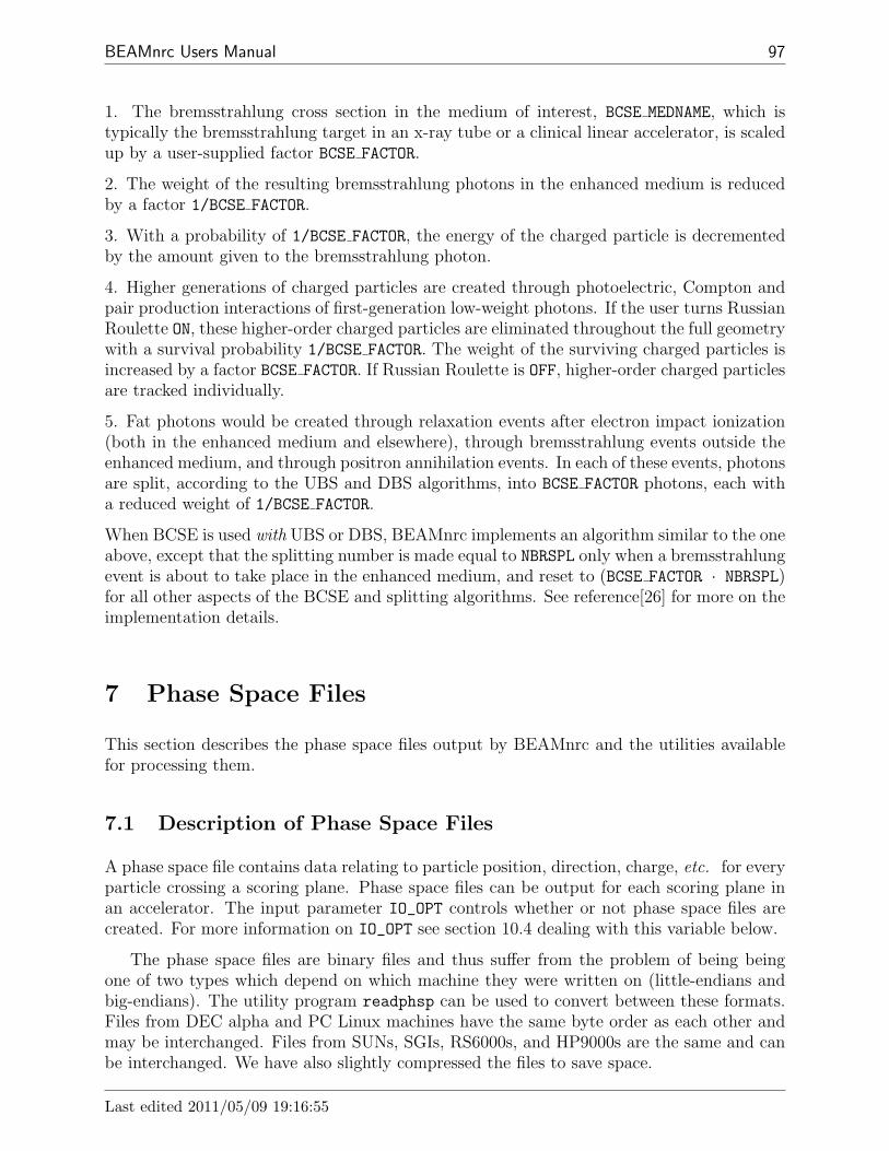
BEAMnrc Users Manual 97
1. The bremsstrahlung cross section in the medium of interest, BCSE MEDNAME, which istypically the bremsstrahlung target in an x-ray tube or a clinical linear accelerator, is scaledup by a user-supplied factor BCSE FACTOR.
2. The weight of the resulting bremsstrahlung photons in the enhanced medium is reducedby a factor 1/BCSE FACTOR.
3. With a probability of 1/BCSE FACTOR, the energy of the charged particle is decrementedby the amount given to the bremsstrahlung photon.
4. Higher generations of charged particles are created through photoelectric, Compton andpair production interactions of first-generation low-weight photons. If the user turns RussianRoulette ON, these higher-order charged particles are eliminated throughout the full geometrywith a survival probability 1/BCSE FACTOR. The weight of the surviving charged particles isincreased by a factor BCSE FACTOR. If Russian Roulette is OFF, higher-order charged particlesare tracked individually.
5. Fat photons would be created through relaxation events after electron impact ionization(both in the enhanced medium and elsewhere), through bremsstrahlung events outside theenhanced medium, and through positron annihilation events. In each of these events, photonsare split, according to the UBS and DBS algorithms, into BCSE FACTOR photons, each witha reduced weight of 1/BCSE FACTOR.
When BCSE is used with UBS or DBS, BEAMnrc implements an algorithm similar to the oneabove, except that the splitting number is made equal to NBRSPL only when a bremsstrahlungevent is about to take place in the enhanced medium, and reset to (BCSE FACTOR · NBRSPL)for all other aspects of the BCSE and splitting algorithms. See reference[26] for more on theimplementation details.
7 Phase Space Files
This section describes the phase space files output by BEAMnrc and the utilities availablefor processing them.
7.1 Description of Phase Space Files
A phase space file contains data relating to particle position, direction, charge, etc. for everyparticle crossing a scoring plane. Phase space files can be output for each scoring plane inan accelerator. The input parameter IO_OPT controls whether or not phase space files arecreated. For more information on IO_OPT see section 10.4 dealing with this variable below.
The phase space files are binary files and thus suffer from the problem of being beingone of two types which depend on which machine they were written on (little-endians andbig-endians). The utility program readphsp can be used to convert between these formats.Files from DEC alpha and PC Linux machines have the same byte order as each other andmay be interchanged. Files from SUNs, SGIs, RS6000s, and HP9000s are the same and canbe interchanged. We have also slightly compressed the files to save space.
Last edited 2011/05/09 19:16:55
98 NRCC Report PIRS-0509(A)revL
The first record in a file is different from the others and contains the following information.
MODE RW The file mode: it can be either ’MODE0’ or ’MODE2’ depending on whetherZLAST is included in the phase-space parameters.
NPPHSP The total number of particles in the file.
NPHOTPHSP The total number of photons in the file.
EKMAXPHSP The maximum kinetic energy of the particles stored in the file.
EKMINPHSPE The minimum electron kinetic energy (MeV).
NINCPHSP The number of particles incident from the original (non-phase space) sourceused to generate the phase space file.
Where a phase space file is generated by a simulation using a phase space file as thesource (ISOURC=21), in the output phase space file, NINCPHSP, the equivalent number ofparticles incident from the original non-phase space source, is equal to
NINCPHSP =IHSTRY + (NRCYCL + 1) (NPASS ph sp + NFAT ph sp)
NPPHSPsource∗ NINCPHSPsource
where IHSTRY is the number of histories run, NPASS ph sp is the number of particles rejectedfrom the source because they were multiple passers, NFAT ph sp is the number of fat photonsrejected from the source (only if directional bremsstrahlung is used–see section 6.3.4), andNRCYCL is the number of times each particle in the source is recycled (see section 4.13). Thevalue of NINCPHSP is stored in any phase space files generated by the phase space sourceand is also used to normalize doses and fluences resulting from the phase space source.Thus, NINCPHSP, doses and fluences are traceable back to the original source. For example,consider a model of a 60Co unit which is broken into 2 components. In the first part, thesource capsule is modelled and a phase space file created with all the particles leaving thesurface of the capsule. Here all outputs are normalized per photon from the 60Co. In thesecond stage, the phase space file from the first part is used as input to a model of thecollimator system. Here again the outputs are normalized per photon from the 60Co, thusautomatically maintaining the “natural” normalization.
Each record in a phase space file contains the following information about a particle (inthis order):LATCH, E, X, Y, U, V, WT, (ZLAST)
where:
LATCH contains the particle charge, IQ, the number of times the particle has crossed thescoring plane, NPASS, and information which allows the particle’s history to be traced(see section 8 below). The value of LATCH in the phase space file is not the same asthat internal to BEAMnrc or other analysis codes because of the compression used.
E is the particle total energy (kinetic and rest mass, single precision). This is set negative ifthis is the first particle scored from a new primary (ie from a non-phase space source)history.
7 PHASE SPACE FILES 7.1 Description of Phase Space Files
BEAMnrc Users Manual 99
X is the particle X-position (cm)
Y is the particle Y-position (cm)
U is the X-direction cosine
V is the Y-direction cosine
WT is the particle’s weight; WT also carries the sign of W, the Z-direction cosine
ZLAST is the Z-position of last interaction for photons and is the Z-position of where anelectron or its ancestor was set in motion by a photon (i.e. it does not flag the creationsite of delta rays. This variable is in brackets because its inclusion in the phase spacefile depends upon the setting of the input variable IZLAST (see section 10.6 on IZLAST).If a particle does not interact, ZLAST is the value it had as it entered the simulation(ZIN).
The magnitude of the Z-direction cosine, W, is determined from W =√
1− (U2 + V 2).The particle’s charge is stored in bits 29/30 of LATCH and recovered when read in.
We set E negative for the first particle scored by each new primary (non-phase space)history in order to be able to group scored quantities (energy deposited, fluence, etc) ac-cording to primary history when a phase space file is used as a source. This is necessaryto account for correlations between incident particles and ensures a correct estimate of theuncertainty on the scored quantities [17]. The negative E marker is propagated to phasespace files generated using a phase space source, so that, even in these second-generationfiles, particles can be grouped according to the original primary histories. When a negativeE is read from a phase space source, the primary history counter is incremented and theparticle’s energy is set to |E|.
If you are using an old phase space file without negative E markers as a source, scoredquantities will be grouped according to incident particle instead of primary history. BEAM-nrc will output a warning that uncertainties may be underestimated because correlationsbetween incident particles cannot be accounted for. However, we have shown that in mostcases the underestimates in uncertainty caused by not taking correlations into account arenot significant [17].
When BEAMnrc writes a phase space file, it opens the file usingACCESS = ’direct’, FORM = ’unformatted’, RECL = ’length’.The FORM=’unformatted’ statement ensures that the file will be stored in a compressedformat, requiring less disk space. The record length, ’length’, depends on the machinebeing used to run BEAMnrc; on SUN stations and Linux PC’s, ’length’ is the numberof bytes/record (28 or 32 [with ZLAST]); on SGI and DEC alpha machines, ’length’ is thenumber of variables stored in a record (7 or 8 [with ZLAST]). Internally ‘length’ is determinedas 7*$RECL_FACTOR or 8*$RECL_FACTOR (with ZLAST), where the value of the macro is 1 or4 and is defined in $HEN_HOUSE/lib/${my_machine}/machine.mortran.
The format of phase space files opened withACCESS = ’direct’, FORM = ’unformatted’ is called ’MODE0’ if ZLAST is not scoredand ’MODE2’ if ZLAST is scored. The ’MODE0’ or ’MODE2’ designation appears in the
Last edited 2011/05/09 19:16:55 7.1 Description of Phase Space Files

100 NRCC Report PIRS-0509(A)revL
first record of a phase space file along with the total number of particles contained in thefile, the number of photons, maximum kinetic energy of any particle in the file, minimumkinetic energy of electrons, and the number of particles incident from the original source.
An older version of BEAM opened files in compressed format but withACCESS=’sequential’. These older files are designated ’MODE1’ without ZLAST and’MODE3’ with ZLAST. The current version of BEAM requires conversion of files in the olderformat to access=’direct’ format before adding new phase space data to them. The readphspprogram described below performs this conversion.
Phase space files have extension .egsphsp# where # is the number of the scoring planein the accelerator. By default, the maximum number of scoring planes is 3, but this can beadjusted as described in section 2.11.
BEAMnrc makes use of macros stored in $HEN HOUSE/utils/phsp macros.mortran toread and write the phase space files. Currently, we have optimised the writing macrosto store up and write 1000 particles at a time. This has been found to save network time.Certainly, there are other read/write optimisations that could be made, however, in a normalaccelerator simulation, only a small fraction of the simulation time is taken up reading fromand writing to phase space files. The source for these macros is kept separately so that usersmay utilise them in their own codes to read or write phase space files. The same macrosare used uniformly throughout the BEAMnrc system (DOSXYZnrc, BEAMDP, BEAMnrcetc.).
7.2 Directory for Phase Space Output
By default, phase space files from an accelerator simulation are written to the directory$EGS HOME/BEAM myaccel (i.e. the accelerator directory). However, you do have the optionto output phase space files to a different directory. This is particularly useful if you arewriting large phase space files and, due to disk space limitations, you want to write themdirectly to a /temp storage directory on another machine (provided it is connected with NFSto the machine(s) you are running on).
BEAMnrc provides two different ways to change the phase space output directory:
In the $OMEGA HOME/beamnrc/beamnrc user macros.mortran file, you can redefine themacro $DIRECTORY-FOR-PHSP, which is currently set to $EGS HOME/BEAM myaccel, toto be the directory you want to write phase space files to. Note that you must pro-vide the full directory path in single quotes (i.e. ’/full path to directory’). Anexample is given in the beamnrc user macros.mortran file. Once you have made thischange, you must recompile your accelerator to put it into effect.
BEAMnrc also has a built-in custom user input that you can use to set the variablePHSP OUTDIR, which redefines the output directory for phase space files. The inputline is:Phsp output directory= /full path to phase space output directory
This must appear in the accelerator .egsinp file in the custom input block delimitedby :Start user inputs: and :Stop user inputs:. The custom input block can be
7 PHASE SPACE FILES 7.2 Directory for Phase Space Output

BEAMnrc Users Manual 101
placed either just before or just after the EGSnrc transport parameters (see Section 12for more about custom inputs). If the input is left blank or omitted entirely, then thephase space output directory defaults to that defined by the $DIRECTORY-FOR-PHSP
macro in beamnrc user macros.mortran (see above). Note that the GUI does not giveyou access to this input. This method of changing the output directory for phase spacefiles has the advantage that the accelerator does not need to be recompiled wheneverthe output directory is changed and that different input files for the same acceleratorcan specify different phase space output directories.
7.3 IAEA-format phase space data
Provided that the user’s system has a working C++ compiler (determined automatically onBEAMnrc installation), then BEAMnrc has the capability to read/write phase space datain IAEA format. This allows the user to add to or make use of data from the IAEA’s onlineaccelerator phase space database at:www-nds.iaea.org/phsp/phsp.htmlx
7.3.1 IAEA format
A complete description of the IAEA phase space format is given in IAEA’s technical reportINDC(NDS)-0484[28], which is available from the online phase space database indicatedabove. The format is quite flexible in terms of the amount of data that is stored. Thissection gives a brief description of the IAEA data that is output and read by BEAMnrc.
Phase space data in IAEA format is contained in 2 files: the data file (with extension.IAEAphsp) and the header file (with extension .IAEAheader). IAEA-format header andphase space data files output by BEAMnrc have the names inputfile.#.IAEAheader andinputfile.#.IAEAphsp, where # is the scoring plane number.
The IAEA header file output by BEAMnrc contains the following data:
$CHECKSUM: The size of the .IAEAphsp in bytes. This is used when opening an IAEA (touse it as a source or to add more data to it) to make sure that there are no errors inthe file.
$RECORD CONTENTS: A block indicating the data that is stored in the .IAEAphsp file. A“1” beside a variable indicates that this is stored in the .IAEAphsp file. This blockalso indicates how many extra long integers and extra floating point variables arestored. In the case of BEAMnrc, two extra long integers, LATCH and the number ofprimary histories between this particle and the last particle scored, are always stored.In addition, if the input IZLAST=1 (See Section 10.6) then ZLAST, the Z of the lastinteraction site for photons and the creation site for secondary charged particles, isstored as an extra floating point variable.
$RECORD CONSTANT: Values which are set to a constant value. In the case of BEAMnrc, theZ of the scoring plane is stored here (note that this information is not available in a
Last edited 2011/05/09 19:16:55 7.3 IAEA-format phase space data

102 NRCC Report PIRS-0509(A)revL
standard BEAMnrc phase space file).
$RECORD LENGTH: The length of a phase space record in bytes.
$BYTE ORDER: “1234” for little endian machines, “4321” for big endian machines.
$ORIG HISTORIES: No. of primary histories used to generate the phase space data.
$PARTICLES: Total no. of particles represented in phase space data.
$PHOTONS: No. of photons represented in phase space data.
$STATISTICAL INFORMATION PARTICLES: Total weight, min. weight, max. weight, averagetotal energy, min. total energy and max. total energy for each particle type
$STATISTICAL INFORMATION GEOMETRY: min. and max. X and Y of all particles scored.
There are other fields in the header but they are not currently used by BEAMnrc.
The phase space data file (.IAEAphsp) consists of a record of data for each particle scored,where a record consists of:
type: particle type and sign of Z-direction cosine, W (CHAR*1)
E: total energy of the particle (REAL*4)
X: X position of the particle (REAL*4)
Y: Y position of the particle (REAL*4)
U: X-direction cosine (REAL*4)
V: Y-direction cosine (REAL*4)
WT: statistical weight of the particle (REAL*4)
n stat: no. of primary histories since last particle scored (INTEGER*4)
LATCH: value of LATCH variable (INTEGER*4)
ZLAST: Z of last interaction site of photons or site of creation of secondary charged particles(REAL*4). This is only output if the input variable IZLAST=1 (See Section 10.6).
Thus, each record is 33 bytes long without ZLAST and 37 bytes long if ZLAST is included.
Note that, unlike standard BEAMnrc phase space files, LATCH is not modified to carrythe particle charge and NPASS before being written to the phase space file. The charge isstored in type and if this particle has already crossed the scoring plane (NPASS=1) then it issimply not written to the file. On the other hand, the IAEA phase space file stores n stat,the number of primary histories since the last scored event. This allows correlated particlesto be grouped together for uncertainty analysis, similar to the negative energy marker usedin standard BEAMnrc phase space files. Moreover, if the phase space file is used as a source
7 PHASE SPACE FILES 7.3 IAEA-format phase space data

BEAMnrc Users Manual 103
n stat allows an exact calculation of the number of primary histories represented by thephase space data read. This potentially provides a more accurate normalization for scoredquantities, such as dose and fluence, than the estimate of NINCPHSP (See Section 7.1 above)in the case of a standard BEAMnrc phase space source.
7.3.2 Writing IAEA phase space data
By setting the input variable IO OPT=4 (See Section 10.4) you will output the IAEA phasespace data and header files at each scoring plane.
7.3.3 Reading IAEA phase space data
If you are using IAEA-format space data as a source (i.e. ISOURC=21. See Section 4.13above.) then you must specify the full name of the phase space data (.IAEAphsp) file.BEAMnrc will automatically detect the .IAEAphsp extension and read the data in IAEA-format (with an output message indicating this to the user). Note that the header file isassumed to be in the same directory as the phase space data file.
7.4 readphsp
There are several programs and routines in place for processing phase space files. One ofthe most basic of these is the program readphsp located on $OMEGA_HOME/progs/readphsp.readphsp is invoked by:
readphsp inputfile outputfile
where inputfile includes the .egsphsp# extension and is the name of the phase space file tobe converted, and outputfile is the name of the file which will contain the converted data(and must also include any extension you want to add). Note that readphsp retains com-patibility with phase space files having .egs4phsp# extensions generated by EGS4 versionsof BEAM.
readphsp gives the user various file conversion options (eg. from direct access mode tosequential access mode). It can also convert phase space files into a format readable by theCERN program PAW provided that the necessary libraries are present (see below).
readphsp can be used as a byte swapping tool so that phase space files generated onanother type of machine become compatible with the type of machine that readphsp isbeing run on.
The readphsp program also allows selection of a particular charge from a phase spacefile, or a subset of a file can be extracted.
Before converting phase space files readphsp prints a summary of the file contents. Ifthis is nonsense, then very likely the file has the wrong binary format (i.e. was generated ona machine which uses a different binary format). The user should use the option of readphspto swap the bytes of the phase space data to make it compatible with the current machine
Last edited 2011/05/09 19:16:55 7.4 readphsp

104 NRCC Report PIRS-0509(A)revL
before otherwise converting the phase space data to its new form. When using readphsp forbyte swapping, the name of the output file can be the same as that of the input file howeverthe swapped data will overwrite the original data.
Files related to readphsp are on $OMEGA_HOME/progs/readphsp.
Makefile Directs compilation of readphsp. Sources required files such as$HEN HOUSE/lib/config/machine.macros (where config is the name of your config-uration) for the record length factor ($RECL-FACTOR) for 4-byte phase space data onyour particular configuration, and $OMEGA HOME/beamnrc/phsp macros.mortran forphase space reading/writing macros that readphsp makes use of. You must modifyMakefile if you want to compile readphsp with PAW libraries (see below) so thatphase space data can be converted into PAW format. Clear instructions for doing thisare given in the Makefile.
readphsp.mortran the MORTRAN source file.
libpawlib.a, libpacklib.a (optional) Libraries required for the PAW format conversion.These are not included with the distribution because they are proprietary from CERN,but they are available for free from CERN for those working on medical research.
dummy.f which is a routine required to compile readphsp when there are no PAW librariespresent.
Normally, readphsp is compiled as part of the BEAMnrc installation. However, it canbe compiled separately by going into $OMEGA HOME/progs/readphsp and typing make. Thiswill leave behind the executable, readphsp*, in the $HEN HOUSE/bin/config directory.
Note that readphsp does not work with IAEA-format phase space data.
7.5 BEAMDP
Another important program for processing phase space files is the BEAMDP program. For moredetails about running BEAMDP to derive energy, planar fluence, mean energy and angulardistributions from a phase-space file please see the report “BEAMDP as a General-purposeUtility”[13].
8 Tracking a Particle’s History using LATCH
The LATCH variable, associated with each particle in a simulation, is a 32-bit variable usedto track the particle’s history. In the input files there is an opportunity to define a mappingfrom geometric regions to bits (i.e. bit regions) using the IREGION_to_BIT variable. Thus,eg. it is possible that bit 5 corresponds to geometric region 3, and more importantly, one bit,say 3, can correspond to multiple geometric regions, eg. 1,5,8. Thus, although the JAWSmay consist of 6 different geometric regions, they can all be associated with a single bit or bitregion. All regions which are not associated with a bit/bit region by the user are associatedwith bit region 23 by default. Each bit is designated as follows:
8 TRACKING A PARTICLE’S HISTORY USING LATCH 7.5 BEAMDP

BEAMnrc Users Manual 105
bit 0 Set to 1 if a bremsstrahlung or positron annihilation event occurs in the history; 0otherwise(not used for LATCH_OPTION = 1).
bit 1-23 Used to record the bit region where a particle has been and/or has interacted(Note that the bit set for a region is determined by IREGION_TO_BIT for that region)
bit 24-28 Stores the bit region number (as opposed to geometric region) in which a sec-ondary particle is created; if these bits are all 0, the particle is a primary particle (notfor LATCH_OPTION = 1).
bit 29-30 Store the charge of a particle when LATCH is output to a phase space file (seesection 7 on phase space files). During a simulation, bit 30 is used to identify acontaminant particle but this information is not output to the phase space file. Setto 1 if the particle is a contaminant particle; 0 otherwise. Note that if LATCH is notinherited (i.e. when LATCH_OPTION = 1), bit 30 loses its meaning.
bit 31 Set to 1 if a particle has crossed a scoring plane more than once when LATCH is outputto a phase space file (see section 7 on phase space files above)
For secondary particles, recording the region number in which they were created in bits24-28 is equivalent to multiplying the region number by 224, or 16777216. Thus, to retrievethe region of origin of a secondary particles, the LATCH value of the particle must be dividedby 16777216 (i.e. taking the value INT(LATCH/16777216)).
The user controls the protocol for setting LATCH using the LATCH_OPTION input variable.The possible settings of LATCH_OPTION are:
LATCH OPTION = 1 (Non-Inherited LATCH Setting): secondaries do not inheritLATCH values from the primaries that created them; bits 1-23 of a secondary particlecarry no information about the regions its primary parent(s) has(ve) been. This optionmust NOT be used if ICM_CONTAM is non-zero since the ICM_CONTAM option needs bit30.
LATCH OPTION = 2 (Comprehensive LATCH Setting –default): LATCH valuesare passed on to secondary particles from the primaries that created them; bits 1-23 fora secondary particle include all regions in which the secondary particle has been plusthose in which its ancestors have been up to the point where the secondary was created;uses bits 24-28 to record the bit region where secondary particles are created and bit 0to record whether or not a bremsstrahlung photon was involved in a particle’s history.
LATCH OPTION = 3 (Comprehensive LATCH Setting 2): similar to 2, but forphotons bits 1-23 record the regions in which the particles have interacted, rather thansimply the regions in which they have been. After a Compton, pair or photo-electricevent, the charged particles, and in the latter case, also the fluorescent photons, havethe bits 1–23 set for the region in which they are created to treat the case in whichthey are created below cutoff in a manner similar to being created above cutoff (wherethe bits would be set on the first step).
Last edited 2011/05/09 19:16:55
106 NRCC Report PIRS-0509(A)revL
To clarify further the setting of LATCH bits under various LATCH_OPTION values, fig 19and table 2 summarise the situation for a simple photon accelerator. Two electrons enter thesimulation and produce bremsstrahlung photons in the target, bit (and geometric) region1. One photon goes all the way to the scoring plane without interacting and the secondundergoes a pair production event in the flattening filter (bit region 3). The electron escapesfrom the flattening filter an gets to the scoring plane and the positron annihilates in theflattening filter and one of the resulting 511 keV photons gets to the scoring plane. The userhas also defined a contamination scoring plane just above the JAWS ( i.e. ITDOSE_ON=1,ICM_CONTAM=4 (just above the JAWS) and IQ_CONTAM=-1).
8 TRACKING A PARTICLE’S HISTORY USING LATCH

BEAMnrc Users Manual 107
target
flatteningfilter
e−
1
2 primarycollimator
contamination plane
jaws4
23γ e−
1 2 3
3e+
(511 keV)
LATCH
γ
γ
contamination plane
Figure 19: Simple photon accelerator model showing 3 particles reaching the phase spacefile after 2 electrons are incident. Contamination is defined as charged particles crossingthe contamination plane. Table 2 shows the bit settings in LATCH as the particles reach thescoring plane. The bit region numbers are shown in circles.
Table 2: Bit settings in LATCH for the simple example shown in fig 19.Latch option Particle Bit 0 1 2 3 4 23 24-28 301 non-inherited 1 0 1 0 0 0 1 0 0
2 0 0 0 1 0 1 0 03 0 0 0 1 0 1 0 0
2 comprehensive 1 1 1 0 0 0 1 “1” 0inherited 2 1 1 0 1 0 1 “3” 0
where been 3 1 1 0 1 0 1 “3” 13 comprehensive 1 1 1 0 0 0 0 “1” 0
inherited 2 1 1 0 1 0 0 “3” 0where interacted 3 1 1 0 1 0 1 “3” 1
Last edited 2011/05/09 19:16:55

108 NRCC Report PIRS-0509(A)revL
9 Calculating Dose Components
The ability to trace a particle’s history using LATCH also allows doses to be broken down intotheir components. In any dose zone, BEAMnrc is able to break dose down in 2 ways: dosefrom contaminant particles (identified on the basis of their charge only); or dose includingonly and/or excluding only contributions arising from particles with certain user-specifiedLATCH bit settings (this is called “bit filtering”).
The input variables associated with dose component calculations are:
ITDOSE ON 0 to calculate total dose only (default); 1 to calculate dose components
The following variables are associated with contaminant dose calculation and are onlyrequired if ITDOSE_ON = 1.
ICM CONTAM contaminant particles are identified upon entering the top of CM numberICM_CONTAM if 1 ≤ ICM_CONTAM ≤ total number of CMs (previously, this range wasrestricted to 1 < ICM_CONTAM ≤ total number of CMs); if it is set to 0, no contaminantdose will be calculated.
IQ CONTAM The charge of the contaminant particles (0 for photons and 1 for chargedparticles); all particles with this charge will be marked as contaminant particles (bysetting LATCH bit 30 of the particles to 1) upon entering the front of CM numberICM_CONTAM.
Contaminant dose is scored in every dose zone. However it is traced back only to those par-ticles identified as having contaminant charge upon entering CM number ICM_CONTAM. Forexample, if IQ_CONTAM = 1, all the charged particles entering CM number ICM_CONTAM willbe marked as contaminant particles and this mark will be passed onto their descendants viaLATCH bit 30. The dose contributed by the contaminant particles and their descendants isthen scored as the contaminant dose. Note that if LATCH_OPTION = 1 LATCH values are nottransferred to descendants (secondaries), and contaminant dose calculations will be mean-ingless. Thus, the contaminant dose option is automatically turned off if LATCH_OPTION = 1.Note also that prior to Sept 2002, contamination was defined as it entered the CM from thefront or the back.
The following variables are associated with bit filtering of dose and are only required ifITDOSE_ON = 1:
LNEXC number of dose components that exclude contributions from particles with user-specified LATCH bits set (bit filters). LNEXC = 0 is allowed. LNEXC <= $MAXIT - 3
where $MAXIT can be changed from its default value of 12 (as described in section 2.11).
L N EXC(I,31) (I = 1,2,...,LNEXC) Bit filter for determining which particles to ex-clude from dose component I; each of the LNEXC components requires input of aseparate bit filter; a bit filter consists of a sequence of up to 31 LATCH bit numbers ona single record (range 1-31), separated by commas; particles with any of the listed bitsset are excluded from dose component I.
9 CALCULATING DOSE COMPONENTS

BEAMnrc Users Manual 109
LNINC number of dose components with contributions only from particles with user spec-ified bit filters which are a combination of inclusive and possibly exclusive patterns.LNINC = 0 is allowed. LNINC <= $MAXIT - LNEXC - 3.
L N INC(I,31) (I = 1,2,...,LNINC) Bit filter for determining which particles to includein dose component I; each of the LNINC components requires input of a separate bitfilter which consists of 2 groups of LATCH bit numbers (range 1-31) separated by a0; contributions from the particles with any of the LATCH bits in the first group ofL_N_INC(I,31) set and none of those in the second group set are included in dosecomponent I.
For example, if the inputs for L_N_INC(I,31) are 2,3,5,0,1,4,0,..., then dose componentI will include the contributions from the particles with any of the LATCH bits 2, 3 or5 set (=1) and both LATCH bits 1 and 4 not set (=0); the status of other LATCH bitswill have no effect on this dose component. If the inputs are 1,2,3,0,0,...,(equivalently1,2,3,) the dose component will include the contributions from the particles with anyof the LATCH bits 1, 2 or 3 set (=1). Note that no dose will be scored if one inputs0,2,3,5,0,...
Note that bit 0 of LATCH can not be used for the above dose component calculations.
Bit filtering of dose provides a particularly powerful tool for determining dose contribu-tions. In view of the information stored in LATCH (see section above), dose contributions canbe separated according to what regions particles have passed through/interacted in, whetherthe particle is a primary or secondary, if the particle is a secondary then where it was created,whether or not the particle is a contaminant, and any combination of these.
It should be noted that if directional bremsstrahlung splitting (DBS) is used in a BEAMsimulation then an additional dose component, the total dose minus the dose due to fatparticles, is automatically output to the .egslst and .egsplot files. see section 6.3.4 formore details.
10 Other Input Variables
This section provides descriptions of main BEAMnrc input variables not covered above.
10.1 IWATCH
IWATCH controls output to the screen (interactive run) or to the .egslog file (batch run)during beam execution. The possible settings are:
= 0 (default) On completion of each batch, outputs information about the batch (eg elapsedtime, CPU time, elapsed/CPU time, random number used to begin batch, # of randomseeds used in the batch, total number of histories run up to and including the currentbatch, the total number of particles scored in the first phase space file)
Last edited 2011/05/09 19:16:55

110 NRCC Report PIRS-0509(A)revL
= 1 Outputs batch information plus, after every particle interaction, outputs complete in-formation about the particle(s) involved (eg interaction type, particle type, position ofparticle on stack, particle energy, X-Y-Z position of particle, U-V-W direction cosines,LATCH value of particle, region # of particle); also informs user when a particle is beingdiscarded, when a particle is passing from one CM to another
= 2 Similar to 1 only complete particle information is output at every step; also outputstotal dose in a region whenever energy is deposited there
= 3 Similar to 2 only particle and dose information are output whenever dose is deposited.
= 4 Outputs same information as 0 plus .egsgph and egsgeom files for graphical represen-tation of the accelerator and particle paths using EGS_Windows[16].
10.2 ISTORE
ISTORE controls how BEAMnrc reads and writes the state of the random number generator(RNG) used in simulations. The possible settings of ISTORE are:
= 0 (default) BEAMnrc stores the state of the RNG for the 1st history in each batch inthe file .egsrns
= 1 BEAMnrc stores the state of the RNG for every history in the .egsrns file. The randomnumber state of the current history overwrites that of the previous history.
= -1 BEAMnrc reads the state of the RNG for the 1st history from the .egsrns file. Ifthere was an error during a history that caused the history to stop, then you can useISTORE = -1 to rerun the problem history, provided that you first stored the state ofthe RNG for each history using ISTORE = 1.
10.3 IRESTART
IRESTART controls how BEAMnrc treats the current run - either as new or as a continuationof a previous run. The possible settings of IRESTART are:
= 0 (default) BEAMnrc initiates a new run, deleting all of the output files from previousruns of the same name if present (.egslog, .egslst, .egsrns, .egsphsp1, etc.).
= 1 Restart of a previous run; BEAMnrc reads fluence and dose data from the previousrun, the number of histories already run, the time taken by the previous run, and thestate of the random number generator from the last batch of the previous run fromthe .egsdat file; fluence and dose and their statistics are averaged with those from theprevious run; phase space output is appended to that from the previous run; note thatthe number of histories to run in the present run is given by NCASE but the reportedtotal CPU time and number of histories analysed in the output include the historiesand CPU time from the previous run.
10 OTHER INPUT VARIABLES 10.2 ISTORE

BEAMnrc Users Manual 111
= 2 BEAMnrc creates the .egsinp file and then exits without running the simulation.
= 3 BEAMnrc reads dose and fluence data from a previous run in the .egsdat file, performsstatistical analysis on the data and outputs results to .egslst; no simulation is run.
= 4 For analysis of dose and fluence in a simulation that has been split up into parallel jobs.See section 13 page 123 below on parallel processing with BEAMnrc for more details.
10.4 IO OPT
IO_OPT allows user control of phase space output. Some aspects of this variable have alreadybeen covered in section 7 on phase space files. However, it also controls data analysis ofsimplified source models. The possible settings for IO_OPT are:
= 0 (default) Phase space output at each scoring plane
= 1 No phase space output at scoring planes
= 2 No phase space output, but perform data analysis for simplified source models (seeBEAMDP manual).
= 3 Phase space output for the first 100,000 particles across each scoring plane and performdata analysis for simplified source models
= 4 IAEA-format phase space output at each scoring plane
10.5 IDAT
IDAT controls output of the .egsdat file, which contains data from a previous run so thatBEAMnrc is able to restart this run if required. The .egsdat files from parallel jobs arerequired for recombining to obtain the final results (see section 13). Possible settings of IDATare:
= 0 (default) Output energy deposited and fluence data, number of histories completed,elapsed time and the current state of the random number generator to the .egsdat
file upon completion of every batch
= 1 Do not output a .egsdat file
See section 2.10 for a more complete description of the .egsdat file.
Last edited 2011/05/09 19:16:55 10.4 IO OPT

112 NRCC Report PIRS-0509(A)revL
10.6 IZLAST
IZLAST controls whether or not ZLAST is recorded in phase space files. ZLAST is the Z-positionof last interaction for photons and is the Z-position of where an electron or its ancestor wasset in motion by a photon (i.e. it does not flag the creation site of delta rays). The possiblesettings of IZLAST are:
= 0 (default) BEAMnrc does not score ZLAST in phase space files; this means that phasespace files are read and written in compressed “mode0”
= 1 BEAMnrc scores the Z position of last interaction in phase space files; phase space filesare read and written in compressed “mode2”; “mode2” files are approximately 14%larger than “mode0” files; when plotting phase space data with paw, ZLAST replacesthe radial position of a photon (r)
= 2 Same as option 1 and in Addison, BEAMnrc writes the X-Y-Z positions of the last siteof interaction for photons into the .egsgph file. These last sites of interaction can beviewed in 3-D using EGS Windows[16]. IWATCH=4 must not be turned on at the sametime since it also writes to the .egsgph file.
Note that the utility BEAMDP has an option to present graphs of ZLAST in 2-D.
10.7 NCASE
NCASE is the number of histories for this run. Minimum value is 100. Default is 100 if NCASEis set < 100. The number of histories per batch is equal to NCASE/($NBATCH), where $NBATCHis the number of output batches. $NBATCH is set in the beamnrc user macros.mortran fileand is currently equal to 10. The total number of histories after this run will be the sum ofNCASE and the number of histories from the previous run.
Starting with BEAMnrc, the breaking of the run into batches is for saving intermediatedata and diagnostics. It is no longer associated with statistical uncertainties.
Starting with BEAM99, NCASE and other variables related to the number of histories,such as IHSTRY, were made INTEGER*8 variables. This allows >2x10⁹ total histories, andis particularly useful for restarts and parallel runs, where a large number of total historiescan be accrued quite easily. However, INTEGER*8 may cause problems for some Fortrancompilers. For a more detailed description of this problem and how to fix it if it does occur,see section 18 on known bugs/restrictions in BEAMnrc.
10.8 IXXIN, JXXIN
The input values of IXXIN and JXXIN are seeds used to initialize the RANLUX[29, 30]or RANMAR[31, 32] random number generator. Within BEAMnrc, IXXIN is limited tothe range 0<IXXIN≤31328 (defaults to 1802), and JXXIN has the range 0<JXXIN≤30081(defaults to 9373). These ranges/defaults were originally designed for RANMAR, however,
10 OTHER INPUT VARIABLES 10.6 IZLAST

BEAMnrc Users Manual 113
if you are using RANLUX (the new default) then IXXIN is the “luxury level” of the randomnumber generator and must be in the range 0<IXXIN≤4, otherwise, it will automatically beset to the default luxury level of 1 (Note: this means that the BEAM default value for IXXINof 1802 will ultimately get reset to 1 by RANLUX). Also, with RANLUX, the input JXXINcan have a maximum value of 1073741824, however you will have to change the BEAMnrccode to allow this maxium.
Note that IXXIN and JXXIN are only used to initialize the random number generator,and, during a simulation, they no longer reflect the values of the seeds that are actually usedto generate the random numbers. During restarts (IRESTART = 1), the state of the randomnumber generator at the end of the previous run is read from the .egsdat file and is used atthe beginning of the restart. Thus, a restarted run with a total of, eg, 10000+10000 historiesshould generate results identical to a single run of the same simulation with 20000 histories.Also note that when running parallel simulations with BEAMnrc (see section 13), JXXINmust have a different value for each of the individual jobs that make up the simulation. Aproperty of the random number generators being used is that this simple change guaranteesrandom number sequences which are independent.
To switch from the default RANMAR to RANLUX in your BEAM code, either go into$HEN HOUSE/specs/beamnrc.spec and change the line:
RANDOM = $(EGS_SOURCEDIR)ranmar
to:
RANDOM = $(EGS_SOURCEDIR)ranlux
(recommended if you plan on using RANLUX as your default random number generator forall accelerators), or compile an individual accelerator using the command
make RANDOM=$HEN_HOUSE/src/ranlux
10.9 TIMMAX
TIMMAX is the maximum CPU time in hours allowed for this run. TIMMAX defaults to 0.99hours if it is set = 0. At the end of each batch, an estimate is made of how much time isneeded to complete another batch. If the next batch cannot be completed within TIMMAX forthe current run, then BEAMnrc terminates the run and analyses the results for the shortenedrun. The restart feature (see section 10.3 on IRESTART) can be used to continue the run ifneeded and if IDAT (section 10.5) is set to 0 (i.e. the .egsdat files are created). Note thatthe total CPU time reported for a simulation is the sum of the CPU time so far for this runand the CPU time from the previous run, but TIMMAX refers to the present run’s time only.
10.10 ECUTIN
ECUTIN is used together with the Global ECUT input in the EGSnrc input parameters (seesection 11) to define the global electron cutoff energy in MeV. If ECUTIN > Global ECUT inthe EGSnrc inputs, or if the Global ECUT input is missing from the EGSnrc inputs, then
Last edited 2011/05/09 19:16:55 10.9 TIMMAX

114 NRCC Report PIRS-0509(A)revL
ECUTIN is used as global cutoff energy.
As soon as an electron’s total energy falls below the cutoff energy, its history is terminatedand its energy deposited in the current region. The time required for a given calculation isstrongly dependent on the value of ECUT and thus it is important to use as high a value aspossible.
The user can override the Global ECUT with the ECUT’s defined for individual regionswithin CMs (see CM descriptions below). However, if the ECUT for an individual region is<Global ECUT, then it is set equal to the Global ECUT.
Note that AE for the PEGS4 data set used is the lower limit on the value of ECUT used ina given region. The selection of AE also requires some care and is discussed in section 16.2.
Selection of ECUT is complex in general and is dependent on what is being calculated[33,25]. For therapy beams, ECUT can be quite high since low-energy electrons contribute little todose in phantom. For what we consider detailed work, we have used ECUT = 0.700 MeV butmuch higher may be possible. However, if the dose in the monitor chamber is an importantpart of the calculation, lower values of ECUT may be required.
As a general rule of thumb for calculations of dose distributions, ECUT should be chosenso that the electron’s range at ECUT is less than about 1/3 of the smallest dimension ina dose scoring region. This ensures energy is transported and deposited in the correctregion although for electrons which are moving isotropically, this can be a very conservativerequirement.
10.11 PCUTIN
PCUTIN is used together with the Global PCUT input in the EGSnrc input section to definethe global cutoff energy for photon transport in MeV. It is the photon equivalent of ECUTIN.Similar to ECUTIN, if PCUTIN is > the value input for Global PCUT in the EGSnrc inputsection, or if Global PCUT is omitted from the EGSnrc inputs, then PCUTIN is used as theGlobal PCUT. Also the user can override Global PCUT with PCUTs defined for individualregions within CMs.
The exact value of the Global PCUT is not critical in the sense that low values do nottake much more time. A value of 0.01 MeV should generally be used.
10.12 ESTEPIN, SMAX, IDORAY, IFLUOR
These are dummy inputs which used to define the maximum fractional energy loss perelectron step (ESTEPIN), the maximum step length (SMAX), a switch for turning on Rayleighscattering (IDORAY), and a switch to turn on K-shell X-ray fluorescence (IFLUOR). Now allof these transport parameters are handled in the EGSnrc inputs (see section 11), however,the dummy inputs are retained for compatibility with older EGS4 BEAM input files.
10 OTHER INPUT VARIABLES 10.11 PCUTIN

BEAMnrc Users Manual 115
10.13 ICM SPLIT, NSPLIT PHOT, NSPLIT ELEC
ICM SPLIT is used to split photons and electrons at an arbitrary plane within an accelerator.To use this option, the user sets ICM SPLIT equal to the CM # at the top of which the photonsand electrons are to be split. When ICM SPLIT>0, then the user must input NSPLIT PHOT
and NSPLIT ELEC, the splitting number for photons and electrons, respectively, upon enteringthe CM. If NSPLIT PHOT or NSPLIT ELEC is ≤1, then the relevant particle type is not splitat all. Once a particle has been split, the resultant particles carry weight 1/NSPLIT PHOT or1/NSPLIT ELEC. A particle is only split upon entering the user-specified CM from the top(i.e. W(NP) > 0) and if it has not been split by this option before.
Splitting at an arbitrary plane was designed primarily for improving statistics in dosecalculations in a phantom, in which case particles (usually photons) would be split uponentering a phantom at the bottom of the accelerator. Use of this option near the top of anaccelerator may produce undesirable correlations, without much gain in efficiency.
The ICM SPLIT option operates in conjunction with any kind of bremsstrahlung splittingand photon forcing. In the case where ICM SPLIT=NFCMIN (i.e. the arbitrary splitting planecorresponds to the plane at which photon forcing is to begin), the photons are split BEFOREthey are forced to interact.
Currently, if ICM SPLIT=1, then the option is turned on, but no splitting will occur. Wehope to remove this restriction, but if you wish to split particles in CM 1, you can get aroundthe problem, by inserting a dummy CM 1 and setting ICM SPLIT=2.
11 EGSnrc inputs
The use of EGSnrc to simulate charged particle and photon transport in BEAMnrc allowsthe user a greater degree of control over the transport physics than was previously availablein EGS4 versions of BEAM. For most accelerator applications, the default settings in theBEAMnrc code for the EGSnrc parameters should be adequate (these are not the same as theEGSnrc standard defaults). However, there are some cases, such as low energy applications,in which the user will want to vary the EGSnrc transport parameters using the EGSnrcinputs.
EGSnrc inputs appear at the end of a BEAMnrc input file using the new format usedwith the general purpose user EGSnrc user codes. The input occurs between the delimiters:start mc transport parameter: and :stop mc transport parameter:.
In general, EGSnrc inputs must appear in the input file in the format:PARAMETER NAME= parameter value
Note that there is a space between the “=” sign and the parameter value but not before the“=” sign. If you are using the BEAMnrc GUI to set the EGSnrc inputs, then the aboveformat is written to the input file automatically when you save the input parameters.
If any or all of the EGSnrc input parameters is missing, then the default setting will beused. This feature allows BEAM input files to be used directly with BEAMnrc. A betterapproach is to read the old BEAM input file into the beamnrc gui and then save it since
Last edited 2011/05/09 19:16:55 10.13 ICM SPLIT, NSPLIT PHOT, NSPLIT ELEC

116 NRCC Report PIRS-0509(A)revL
this will explicitly add the required EGSnrc inputs to the file.
The following sections describe the EGSnrc inputs required in BEAMnrc. For moreinformation, see the EGSnrc manual[1]. The actual internal variable name associated witheach input appears in brackets.
11.1 Global ECUT (ECUT)
Global ECUT defines the global electron cutoff energy (ECUT) in MeV. This is one of the twoEGSnrc input parameters that is also accessible through the main BEAMnrc input sectionof the input file (the other is Global PCUT described below). Specifically, if ECUTIN in themain BEAMnrc inputs is > Global ECUT, or if Global ECUT is missing from the EGSnrcinput section, then the global value of ECUT is set to ECUTIN. See section 10.10 for a moredetailed discussion of ECUT.
11.2 Global PCUT (PCUT)
Global PCUT defines the global photon cutoff energy (PCUT) in MeV. Similar to Global
ECUT, this EGSnrc input parameter is also accessible through the main BEAMnrc inputsection of the input file. If PCUTIN in the main BEAMnrc inputs is > Global PCUT, or ifGlobal PCUT is missing from the EGSnrc input section, then the global value of PCUT is setto PCUTIN. See section 10.11 for a more detailed discussion of PCUT.
11.3 Global SMAX (SMAXIR)
Global SMAX defines the maximum electron step length in cm. If the default EGSnrc electronstep electron algorithm (see section 11.8) and the exact boundary crossing algorithm areused, then no restriction on maximum step length is needed. However, if using PRESTA-I(the EGS4 standard) as the electron step algorithm or the boundary crossing algorithm,then Global SMAX must be set to a reasonable value (eg 5 cm) to ensure proper electrontransport in low density materials (air). Global SMAX defaults to 5 cm when the PRESTA-Iboundary crossing algorithm (BCA) or electron step algorithm is used is used and 1.E10 cmwhen the EXACT BCA and PRESTA-II electron step algorithm are used.
11.4 ESTEPE (ESTEPE)
ESTEPE is the maximum fractional energy loss per electron step. For accurate electrontransport with default EGSnrc electron step algorithm, ESTEPE should not exceed 0.25 (thedefault). The value of ESTEPE should not be changed unless PRESTA-I is being used as theelectron transport algorithm.
11 EGSNRC INPUTS 11.1 Global ECUT (ECUT)

BEAMnrc Users Manual 117
11.5 XImax (XIMAX)
XIMAX is the maximum first multiple elastic scattering moment per electron step. It is equalto roughly half the average multiple scattering angle squared. Make sure you do not setXIMAX > 1, since this is beyond the range of available multiple scattering data. The defaultvalue of 0.5 should be sufficient for most applications.
11.6 Boundary crossing algorithm (BCA) (bca algorithm)
This controls the algorithm used to transport electrons across region boundaries. There aretwo possible settings of Boundary crossing algorithm: EXACT and PRESTA-I. The defaultfor BEAMnrc is EXACT (same as in EGSnrc itself). The EXACT boundary crossing algorithmwas introduced in EGSnrc to eliminate a known fluence singularity caused by forcing amultiple scattering event at a boundary [34]. In the EXACT case, electrons are transported insingle elastic scattering mode as soon as they are within a distance from the boundary givenby the EGSnrc input Skin depth for BCA (see section 11.7 below). If the PRESTA-I BCAis used boundary crossing is carried out in a manner similar to EGS4/PRESTA. Specifically,the lateral correlation algorithm is turned off if the perpendicular distance from the electronto the boundary is less than Skin depth for BCA (see section 11.7 below) and then, oncethe electron reaches the boundary, a multiple scattering event is forced.
Until 08/06, the default BCA for BEAMnrc was PRESTA-I. However, this has beenswitched to the slower EXACT BCA because it was found that the use of the PRESTA-I canresult in significant overestimates of dose (up to 2.5%) when the CHAMBER componentmodule is used as a depth-dose phantom (see Section 15.3.6). The use of the EXACT BCAis not expected to significantly increase the CPU time in most accelerator simulations. Seethe technical note by Walters and Kawrakow[12] for more information.
11.7 Skin depth for BCA (skindepth for bca)
If Boundary crossing algorithm= PRESTA-I, then Skin depth for BCA is the perpen-dicular distance (in elastic mean free paths) from the boundary at which lateral pathlengthcorrections are turned off and the particle is transported in a straight line until it reachesthe boundary. By default the distance at which to switch off lateral corrections is a fixedvalue calculated by EGSnrc to be the same as that used in the original implementation ofPRESTA in EGS4 and depends on the value of ECUT.
If Boundary crossing algorithm= EXACT, then Skin depth for BCA determines theperpendicular distance (in elastic mean free paths) to the region boundary at which electrontransport will go into single elastic scattering mode. A skin depth of 3 elastic mean freepaths has been found to give peak efficiency in this case and is the default.
If Boundary crossing algorithm= EXACT and Skin depth for BCA is set to a verylarge number (eg 1e10), then the entire simulation will be done in single scattering mode.
Last edited 2011/05/09 19:16:55 11.5 XImax (XIMAX)

118 NRCC Report PIRS-0509(A)revL
11.8 Electron-step algorithm (transport algorithm)
This input determines the algorithm used to calculate lateral and longitudinal correctionsto account for elastic scattering in a condensed history electron step. There are 2 possiblesettings: PRESTA-II (the default) and PRESTA-I. PRESTA-II is the new, more accurate, algo-rithm developed for use with EGSnrc[1]. PRESTA-I is the original PRESTA algorithm withsome modifications[35]. The original PRESTA-I is known to underestimate lateral deflections,to underestimate longitudinal straggling and to produce a singularity in the distribution de-scribing the lateral spread of electrons in a single condensed history. While PRESTA-I maybe accurate enough for high energies (since elastic scattering is weak), it is not recommendedfor low energy applications.
11.9 Spin effects (spin effects)
If Spin effects= on (the default), then elastic scattering cross-sections that take into ac-count relativistic spin effects are used in electron transport. If Spin effects= off, thenscreened Rutherford cross-sections (similar to EGS4) are used for elastic scattering. It shouldbe noted that using Spin effects= on does increase calculation time, however, results aremore accurate and it is ABSOLUTELY necessary for good backscatter calculations.
Including spin effects has a small but distinct effect on calculated depth-dose curves.In low-Z materials such as water, the value of R50 for a given energy is higher than withEGS4/PRESTA. For high-Z materials it is the reverse and backscatter also increases.
11.10 Brems angular sampling (IBRDST)
This input determines the type of angular sampling that is done when a bremsstrahlungphoton is created. If Brems angular sampling= Simple (the default) then bremsstrahlungangles are sampled using only the leading term of modified equation 2BS of Koch andMotz[24, 36]. If Brems angular sampling= KM, then the bremsstrahlung angles are sampledusing the entire modified equation. Brems angular sampling= Simple is adequate at highenergies, however, there is little increase in simulation time associated with using the entiremodified 2BS equation and the entire equation is recommended at low energies. Note thatBrems angular sampling= KM is similar to the bremsstrahlung angular sampling schemeused by the latest version of EGS4/BEAM, with some modifications.
11.11 Brems cross sections (IBR NIST)
This input determines the differential cross-section used for bremsstrahlung interactions. IfBrems cross sections= BH (the default), then Bethe-Heitler cross-sections (Coulomb cor-rected above 50 MeV)[36] are used. These cross-sections are those used by EGS4/BEAM. IfBrems cross sections= NIST, then differential cross-sections from the NIST bremsstrahlungcross-section data base[37, 38] are used. The NIST cross-sections are the basis for radiativestopping powers recommended by the ICRU[39]. The difference between BH and NIST is
11 EGSNRC INPUTS 11.8 Electron-step algorithm (transport algorithm)
BEAMnrc Users Manual 119
negligible for energies > 10MeV, but becomes significant in the keV energy range where theNIST data base is preferred. In either case, the total bremsstrahlung cross sections are thesame. There is also a Brems cross sections= NRC option. The NRC cross-sections arethe NIST cross-sections including corrections for electron-electron bremsstrahlung (typicallyonly significant for low values of the atomic number Z and for k/T ¡ 0.005).
11.12 Bound Compton scattering (IBCMP)
The Bound Compton scattering input is used to determine whether binding effects andDoppler broadening are simulated in Compton (incoherent) scattering events. If this inputis set to Off (the default), then the Klein-Nishina formula[40] is used to determine differentialcross-sections for Compton scattering. This is similar to the treatment of Compton scatter-ing in EGS4/BEAM. If Bound Compton scattering= On, then the original Klein-Nishinaformula is augmented with the impulse approximation[41] to simulate binding effects andDoppler broadening. Simulation of binding effects and Doppler broadening takes extra timeand is only important below 1 MeV and/or if Rayleigh scattering is being simulated (seesection 11.18). A third option, Bound Compton scattering= Norej, is provided which usesthe total bound Compton cross sections (em i.e. no impulse approximation) and does notreject any Compton interactions at run time.
Bound Compton scattering may also be turned on in selected regions (off everywhereelse) using Bound Compton scattering= On in regions together with the inputs Bound
Compton start region and Bound Compton stop region to define the region ranges forwhich bound Compton is to be turned on. Conversely, bound Compton can be turnedoff in selected regions (on everywhere else) by inputting Bound Compton scattering= Off
in regions with Bound Compton start region and Bound Compton stop region used todefine the region ranges where bound Compton is to be turned off. Of course, turning boundCompton on/off in regions is accomplished much more easily in the BEAMnrc GUI. Notethat the Norej option cannot be used on a region-by-region basis.
11.13 Compton cross sections (comp xsections)
If the Bound Compton scattering= Norej option is selected (see above), then the user alsohas the option of specifying their own Compton cross section data using the Compton cross
sections input. Cross section data must exist in the $HEN HOUSE/data directory and thefile name must have the form x compton.data, where x is a name specified by the user. Allvalues of x will appear in the GUI menu where Compton cross section data can be selected.Alternatively, if editing the .egsinp file directly, the form of this input is:
Compton cross sections= x
Default Compton cross section data is contained in the file compton sigma.data and isincluded with the EGSnrc system.
Last edited 2011/05/09 19:16:55 11.12 Bound Compton scattering (IBCMP)

120 NRCC Report PIRS-0509(A)revL
11.14 Radiative Compton corrections (radc flag)
If set to Radiative Compton corrections= On, then radiative corrections for Comptonscattering based on the equations of Brown and Feynman (Phys. Rev. 85, p 231–1952)are used. If set to Off (the default) no corrections are done. Note that if set to On
then the variable SOURCES in the sources.make file for the accelerator (See Section 2.12.4above) must be modified to include $(EGS SOURCEDIR)rad compton1.mortran just before$(EGS SOURCEDIR)egsnrc.mortran.
11.15 Pair angular sampling (IPRDST)
This input determines the method used to sample the positron/electron emission angles(relative to the incoming photon) in a pair production event. There are three possiblesettings of this input: Off, Simple and KM. If it is set to Off, then the positron and electroncreated by pair production have fixed polar angles, θ±, given by θ± = m
Eγ, where m is the
electron rest energy and Eγ is the energy of the original photon. This is similar to methodused to determine positron/electron emission angles in the original version of EGS4. If Pairangular sampling= KM, then equation 3D-2003 in an article by Motz et al[42] is used todetermine the positron/electron emission angles. This option is similar to the samplingtechnique used by the current version of EGS4/BEAM. Finally if Pair angular sampling=
Simple (the default), then only the first term in the the Motz et al equation 3D-2003 is used.The KM option becomes less efficient with increasing accelerator energies and, moreover,involves assumptions that are questionable at low energy. For these reasons, the defaultsetting is Simple.
11.16 Pair cross sections (pair nrc)
The Pair cross sections input determines the cross-sections to use for pair productionevents. If set to BH (the default), then Bethe-Heitler cross sections are used. If set to NRC,then the NRC cross sections found in $HEN HOUSE/data/pair nrc1.data are used. TheNRC setting is only of interest at low energies, where these cross-sections take into accountassymmetry in the positron-electron energy distribution.
11.17 Photoelectron angular sampling (IPHTER)
The Photoelectron angular sampling input determines the sampling method used byEGSnrc to determine the angle of emission of photoelectrons. If Photoelectron angular
sampling= Off (the default), then photoelectrons inherit the direction of the incident pho-ton. If Photoelectron angular sampling= On, then Sauter’s formula [43] is used to de-termine the angle of the photoelectron. Note that, in most applications, we have notobserved any difference between the “Off” and “On” settings of this parameters. Alsonote that, strictly speaking, Sauter’s formula is only valid for K-shell photo-absorptionand is also derived from extreme relativistic approximations. Thus, if the user has a
11 EGSNRC INPUTS 11.14 Radiative Compton corrections (radc flag)
BEAMnrc Users Manual 121
better approach, they can insert it in the $SELECT-PHOTOELECTRON-DIRECTION; macro in$HEN HOUSE/egsnrc.macros.
Similar to bound Compton scattering, photoelectron angular sampling can be turned onor off in selected regions (with the opposite setting everywhere else) by setting Photoelectronangular sampling= On in regions or Photoelectron angular sampling= Off in regions
together with the inputs PE sampling start region and PE sampling stop region todefine the region ranges for which photoelectron angular sampling is to be turned on or off.
11.18 Rayleigh scattering (IRAYLR)
This input determines whether Rayleigh (coherent) scattering is simulated or not. Note thatthis replaces the IDORAY input in the BEAM main inputs (see section 10.12). If Rayleighscattering= On, then Rayleigh events are simulated using the total coherent cross-sectionsfrom Storm and Israel[44] and atomic form factors from Hubbell and Øverbø[45]. This datamust be included in the PEGS4 material data set. If Rayleigh scattering= Off (thedefault), then Rayleigh events are not simulated. Rayleigh scattering is only recommendedfor low energy (< 1 MeV) simulations. Also, for proper simulation with Rayleigh eventsincluded, bound Compton scattering (see section 11.12 above) should also be turned on.
Rayleigh scattering can be turned on or off in selected regions (with the opposite settingeverywhere else) using Rayleigh scattering= On in regions or Rayleigh scattering=
Off in regions and the inputs Relaxations start region and Relaxations stop region
to define the region ranges for turning Rayleigh scattering on or off.
EGSnrc also allows the user to specify custom Rayleigh form factors for specified media.To do this, the user must set Rayleigh scattering= custom and then specify the list ofPEGS4 media in additional input ff media names= and the list of files containing customform factors for each specified medium in the additional input ff file names= .
11.19 Atomic Relaxations (IEDGFL)
This input determines whether or not the relaxation of atoms to their ground state afterCompton and photoelectric events is simulated. If Atomic Relaxations= On, then relax-ation after Compton and photoelectric events is simulated via the emission of any combi-nation of K-, L-, M- and N-shell fluorescent photons, Auger electrons and Coster-Kronigelectrons. The lower energy limit for relaxation processes is 1 keV. Thus, only relaxationin shells with binding energy > 1 keV is simulated. If Atomic Relaxations= Off (the de-fault), then atomic relaxations are not simulated. In this case, when there is a photoelectricevent, EGSnrc transfers all of the photon energy to the photoelectron. This is differentfrom EGS4/BEAM, where the binding energy of the electron is subtracted and depositedon the spot. Both approaches are approximations, but the EGSnrc approach is more ac-curate. Atomic Relaxations= On is only recommended for low energy applications. Notethat the Atomic Relaxations option supersedes the IFLUOR option in EGS4/BEAM (seesection 10.12), which only simulates emission of K-shell fluorescent photons after photoelec-tric events.
Last edited 2011/05/09 19:16:55 11.18 Rayleigh scattering (IRAYLR)

122 NRCC Report PIRS-0509(A)revL
Similar to bound Compton, photoelectric angular sampling and Rayleigh scattering,atomic relaxations can be turned on/off in selected regions (with the opposite setting ev-erywhere else) using Atomic Relaxations= On in regions or Atomic Relaxations= Off
in regions and the inputs Relaxations start region and Relaxations stop region
to define the region ranges for which relaxations are to be turned on/off.
11.20 Electron impact ionization (eii flag)
This input determines what, if any, theory is used to simulate electron impact ionization.The possible values are “off” (the default), “on”, “Casnati”, “Kolbenstvedt”, and “Gryzin-ski”. When “on” is selected, Kawrakow’s electron impact ionization theory[46] is used. Forthe other selections, the theory associated with the name given is used. See the EGSnrcManual[1] for more details.
Since the details of electron impact ionization are only relevant at keV X-Ray energies,the default “off” setting should be used in most linac simulations.
11.21 Photon cross sections (photon xsections)
This selects the photon interaction cross-sections to use in the simulation. Cross-sectionsincluded with the BEAMnrc/DOSXYZnrc distribution (and, thus, the possible settings ofphoton xsections immediately after installation are): “Storm-Israel” (the default), “epdl”and “xcom”. The Storm-Israel cross-sections are the standard PEGS4 cross-sections. The“epdl” setting will use cross-sections from the evaluated photon data library (EPDL) fromLawrence Livermore[47]. The “xcom” setting will use the XCOM photon cross-sections fromBurger and Hubbell[48]. Note that the EGSnrc transport parameter input routine is codedin such a way that, if you are editing the .egsinp file directly instead of using the BEAMnrcGUI, the default Storm-Israel cross-sections can only be specified by leaving out the Photon
cross sections input line altogether. This is taken care of automatically if you are usingthe GUI to set this parameter.
You can also use your own customized photon cross-section data. To do this, you mustcreate the files x pair.data, x photo.data, x rayleigh.data and x triplet.data (where“x” is the name of your cross-section data) which contain cross-sections for pair production,photoelectric events, rayleigh scattering and triplet production, respectively. These files mustbe in your $HEN HOUSE/data directory. Once these files are in place, then “x” will appearin the pull-down menu in the GUI where photon cross-sections are specified. Alternatively,if you are editing the .egsinp file directly, you can enter the line:
Photon cross sections= x
inside the block of EGSnrc transport parameter inputs.
11 EGSNRC INPUTS 11.20 Electron impact ionization (eii flag)

BEAMnrc Users Manual 123
11.22 Photon cross-sections output (xsec out)
The input Photon cross-sections output can be set to On to output the file$EGS HOME/BEAM accelname/inputfile.xsections which contains the photon cross sectiondata used in the simulation. Default is Off.
12 Custom user inputs
If custom input parameters are required (for any modifications that you have made tobeamnrc.mortran), then it is recommended that you include them in the .egsinp file be-tween the delimiters: :start user inputs: and :stop user inputs:. This section, ifrequired, can appear either immediately before or immediately after the EGSnrc transportparameters (see Section 11 above). You will not have access to custom inputs through theGUI, but by putting them between the delimiters you ensure that they will not be “wipedout” if you modify/save the input file using the GUI at some point.
The format of custom inputs will be similar to that for the EGSnrc transport parameters:PARAMETER NAME= parameter value
Where PARAMETER NAME can either be the actual name of the input variable or a descriptivetext string. Note the space between the parameter value and the “=” sign.
The current release of BEAMnrc includes a a custom input for redefining the outputdirectory for phase space files, PHSP OUTDIR (see Section phspoutdirsect for more informationabout this). In general, however, it is up to the user to modify beamnrc.mortran to read intheir custom input parameters.
13 Parallel Processing with BEAMnrc
A BEAMnrc simulation can be split into smaller jobs which can then be run on differentprocessors in parallel to reduce the elapsed time required for a simulation. Parallel processingrequires that you be running in Unix/Linux and that you have a network queuing systemsuch as PBS or NQS.
In previous versions of BEAMnrc, the Unix script pprocess was used to automaticallycreate the individual input files for parallel jobs and submit them (also automatically settingthe random number seeds to a different values in each input file and the phase spacesource inputs, IPARALLEL and PARNUM). This method of parallel processing had a majorlimitation, though, in that each job consisted of the same number of histories, making thetotal simulation time dependent on the slowest CPU.
In the current version of BEAMnrc, parallel processing is accomplished much more effi-ciently using a built-in parallel processing functionality.
To submit a parallel job, use the batch submission command, exb (discussed in detail insection 2.7.1). The command syntax for a parallel job is:
Last edited 2011/05/09 19:16:55 11.22 Photon cross-sections output (xsec out)

124 NRCC Report PIRS-0509(A)revL
exb BEAM_myaccel inputfile pegsdata [short|medium|long] [batch=batch_system] p=N
where N is the number of parallel jobs to submit (see Section 2.7.1 for a detailed discussionof the other inputs).
Once this command is entered, the script $HEN HOUSE/scripts/run user code batch
(to which exb is aliased) enters a loop which submits BEAM myaccel to the batch queue N
times. Each submission has the form:
BEAM_myaccel -i inputfile -p pegsdata -P n_parallel -j i_parallel
where n parallel=N and i parallel takes on values 1,2,..., n parallel, depending onwhich job is being submitted. For each parallel job, BEAMnrc will create a temporary work-ing directory (see section 2.9 for more on temporary working directories), and the output filesfrom the i parallelth run will have the naming scheme inputfile w[i parallel].egslog,inputfile w[i parallel].egslst, inputfile w[i parallel].egsphsp1,inputfile w[i parallel].egsdat, etc. Note that N different input files are not created,and that all parallel runs make use of the original input file.
On submission of the first job (i parallel=1) BEAMnrc will create a file, inputfile.lock,in the BEAM myaccel directory. The .lock file, or job control file, is accessed and updatedby all parallel jobs and contains the number of histories remaining to be run, n left, andthe total number of jobs running, n job, among other quantities.
Before beginning a run, a parallel job opens the .lock file and reads n left (the filecannot be read by more than one job at a time). If n left>0, then there are still historiesto run, and the job begins execution. Rather than each job running NCASE/n parallel
histories (as in the old parallel processing scheme), each job runs only a fraction, or chunk,of this number at a time. Thus, the maximum number of histories that a job runs at a time isNCASE/(n parallel*$N CHUNK), where $N CHUNK is defined in $HEN HOUSE/src/egsnrc.macros
and is set to a default value of 10. If n left happens to be less than NCASE/(n parallel*$N CHUNK),then the job will run n left histories. Before beginning the run, the job updates the .lock
file, decrementing n left by the number of histories it is about to run, and incrementingn job if this is the first run for this job. After the job has finished its chunk of histories, itwill loop back to the beginning of the simulation, read the contents of the .lock file again,and determine whether another chunk of histories needs to be run.
Doing parallel simulations in chunks like this prevents jobs that are running on slowerCPU’s from tying up large portions of the simulation and, hence, dominating the totalelapsed time required.
If, on opening the .lock file, a parallel job finds that n left=0 (ie no more histories torun), then it immediately exits the simulation loop, analyzes the data from its runs for outputto the inputfile w[i parallel].egslst file, moves all output files out of its temporaryworking directory, deletes this directory, and decrements n job. If, after decrementing n job,n job=0, then this is the last job to stop running, and it automatically calls the EGSnrcMPsubroutine egs combine runs to combine the results from all parallel jobs (see section 13.3below).
13 PARALLEL PROCESSING

BEAMnrc Users Manual 125
13.1 Random Number Seeds with Parallel Jobs
It is important that each parallel job start with a different state of the random numbergenerator, otherwise you will end up combining identical results at the end of a parallel run,compromising both the results and the uncertainty estimate on them. BEAMnrc avoidsthis problem by automatically incrementing the second random number seed, JXXIN (seesection 10.8) for each parallel job. So for job number i parallel:
JXXIN = JXXINinput − 1 + i parallel (2)
where JXXINinput is the value of JXXIN in inputfile.egsinp.
13.2 Phase Space Sources with Parallel Jobs
When running parallel jobs that use a single phase space source (see section 4.13), it isimportant that the entire source be evenly sampled over all jobs. In order to facilitate this,BEAMnrc divides the source into n parallel*$N CHUNKS equal partitions. Each chunk ofthe run then uses a different partition of the source.
The number of particles in each source partition, p per phsp chunk, is given by:
p per phsp chunk =NNPHSP
(n parallel ∗ $N CHUNKS)(3)
where NNPHSP is the total number of particles in the phase space source. Before a paralleljob starts a chunk of histories, it calculates which chunk of the total histories it is about torun, n run chunk, using the equation:
n run chunk =(NCASE− n left)
NCASE∗ (n parallel ∗ $N CHUNKS) (4)
Recall that n left is the total number of histories remaining AFTER this run begins. Thepartition of the phase space source used by this chunk of histories is then given by:
(n run chunk− 1) ∗ p per phsp chunk + 1 ≤ INPHSP ≤ n run chunk ∗ p per phsp chunk
(5)where INPHSP is the particle number used.
Note that particles may be recycled within a partition, depending on the setting of NRCYCL(see section 4.13). Also, if all the particles in a partition are used up during a run, the parti-tion is restarted at its first particle (ie INPHSP = (n run chunk-1)*p per phsp chunk+1).
13.3 Combining Results from Parallel Jobs
The last parallel job to finish running automatically combines the results of all parallel runsby calling the EGSnrcMP subroutine egs combine runs. This subroutine loops throughi parallel=1,...,n parallel and, for each value of i parallel, calls the BEAMnrc subrou-tine combine results. combine results opens the file inputfile w[i parallel].egsdat,
Last edited 2011/05/09 19:16:55 13.1 Random Number Seeds with Parallel Jobs

126 NRCC Report PIRS-0509(A)revL
reads the values of∑nhist
i=1 (energy deposited)i,∑nhist
i=1 (energy deposited)2i ,
∑nhisti=1 (fluence)i
and∑nhist
i=1 (fluence)2i (where nhist is the number of primary histories) in each dose or flu-
ence scoring zone, and adds these values to their respective totals over all parallel jobs. Oncethe results from all parallel jobs have been summed, BEAMnrc then calculates the doses,fluence values and their uncertainties [17] for the combined run in the same way it wouldcalculate the results of a single run.
The results of the analysis will be output to inputfile.egslst. It indicates whichinputfile w[i parallel].egsdat have been added together followed by full output of thedose and fluence results.
Note that the .egsdat files are essential for combining parallel runs. Thus, if you arerunning in parallel, you must have the input variable IDAT=0 so that the .egsdat files areoutput (see section 10.5, page 111 for more information about IDAT).
Parallel runs can be combined manually by re-running your accelerator with the inputvariable IRESTART=4 (in the GUI, this is equivalent to setting the Run option to “analyzeparallel jobs”) after all parallel jobs have finished. Use of IRESTART=4 is generally notnecessary now that the last job automatically combines parallel results, however, it may beuseful if, for some reason, all of the .egsdat files were not moved out of their temporaryworking directories or if you wish to add more .egsdat files from a separate group of parallelruns. For more information on IRESTART options, see section 10.3.
The process of combining parallel runs described above does not combine phase space filesgenerated by the parallel jobs. These must be combined separately using the MORTRANaddphsp utility described in the next section.
13.4 Combining Phase Space Files from Parallel Runs using addphsp
Phase space files from parallel runs (with a naming scheme:inputfile w[i parallel].egsphsp[scoringplanenumber]) are not automatically combinedat the end of the run. However, the MORTRAN utility, addphsp, can be used to combinephase space files after all parallel jobs are finished.
To use addphsp, simply go to the accelerator directory (ie where the phase space files arelocated) and type:
addphsp inputfile outputfile ipar [istart] [iscore] [i_iaea]
where inputfile is the name of the original input file (no .egsinp extension), outputfileis the name of the output file for the concatenated phase space data (a .egsphsp[iscore]
extension is added automatically), ipar is the number of parallel jobs being added, istartis the job number at which adding begins (ie the first value of i parallel)–defaults to 1,iscore is the scoring plane number for which you are combining phase space files (i.e. areyou adding .egsphsp1, .egsphsp2 or .egsphsp3 files?)–defaults to 1, and i iaea is set to1 if you are adding IAEA-format phase space files–default is 0.
addphsp then concatenates the phase space files inputfile w[istart].egsphsp[iscore],inputfile w[istart+1].egsphsp[iscore], ...,inputfile w[istart+ipar-1].egsphsp[iscore].If you are missing some of the phase space files in the series addphsp will automatically skip
13 PARALLEL PROCESSING13.4 Combining Phase Space Files from Parallel Runs using addphsp

BEAMnrc Users Manual 127
over those and just concatenate those that are available.
In the case of IAEA-format phase space files, the naming scheme is different, and addphsp
concatenates the files inputfile w[istart].iscore.IAEAphsp,inputfile w[istart+1].iscore.IAEAphsp, ...,inputfile w[istart+ipar-1].iscore.IAEAphsp.The corresponding .IAEAheader files (em i.e. inputfile w[istart].iscore.IAEAheader,etc) are assumed to be in the same directory. Output will be to the filesoutputfile.iscore.IAEAphsp and outputfile.iscore.IAEAheader. IAEA functionalityin addphsp requires that EGSnrc/BEAMnrc be installed on a machine with a working C++compiler. See Section 7.3 for more information on the IAEA phase space format.
Note that addphsp requires twice the disk space of the total size of all phase space filesbeing combined, since files are not automatically deleted after they are added.
addphsp makes use of the record length factor ($RECL-FACTOR) for 4-byte phase spacedata found in $HEN HOUSE/lib/config/machine.macros, some of the phase space read-ing/writing macros contained in $HEN HOUSE/utils/phsp macros.mortran (see section 7,page 97), some of the IAEA-format reading/writing macros in$HEN HOUSE/utils/iaea phsp macros.mortran (only if installed with a working C++ com-piler), and some of the macros found in $HEN HOUSE/src/egsnrc.macros.
Normally, addphsp is compiled as part of the BEAMnrc installation. However, you cancompile it separately by going into $OMEGA HOME/progs/addphsp and typing make. Theexecutable, addphsp*, will be put into directory $HEN HOUSE/bin/config.
13.5 Parallel Jobs Run from the GUI
You can start parallel jobs from the BEAMnrc GUI. Select “Run” from the “Execute” menuand the running window that opens up will allow you to select “run in parallel”, together withthe number of parallel jobs. Note that on selecting “run in parallel”, the GUI automaticallyswitches to “batch” mode if this has not already been selected. You can then select thequeue (“short”, “medium” or “long”) that you would like to submit the parallel jobs to. Thequeuing system used defaults to PBS, unless specified otherwise by the $EGS BATCH SYSTEM
environmental variable.
13.6 Restarting Parallel Jobs
Parallel runs can be restarted (by setting IRESTART=1 in inputfile.egsinp) provided thatyou have the .egsdat files from all of the previous individual parallel jobs available inyour $EGS HOME/BEAM myaccel directory. If you are using a phase space source, however,restarting presents a problem in that a particular partition of the source may get used bya different job the second time around. At the end of the run, results from the seconduse of this partition will be recombined with those from its first use with no attentionpaid to the correlation between the two results. This will result in the uncertainties beingunderestimated. We recommend that you do not restart a parallel run if you are using aphase space source.
Last edited 2011/05/09 19:16:55 13.5 Parallel Jobs Run from the GUI

128 NRCC Report PIRS-0509(A)revL
14 Statistics in BEAMnrc
Starting with the February 2002 release of BEAMnrc, a history-by-history method of es-timating uncertainties was implemented in BEAMnrc[17]. This method offers considerableimprovements over the method of statistical batches used up until then.
The history-by-history method involves grouping scored quantities (eg fluence, energydeposited) according to primary history during a run and then determining the root meansquare standard deviation on the mean of the groupings. For most sources, there is nodifference between a primary history and an incident particle. However, for phase spacesources, where more than one incident particle can be traced back to a single primary history,it is important to group according to primary history in order to account for correlationsbetween the incident particles.
For more information, see the report on history by history statistics in BEAMnrc andDOSXYZnrc[17].
15 Component Modules
15.1 Introduction
One of the design features of BEAMnrc is that each part of the accelerator or source unitis considered to be a single component module which takes up an horizontal slab portion ofthe accelerator. These component modules are re-usable and are all completely independent.They communicate with the rest of the system in certain well specified ways. The purposeof this section is to list all component modules currently used at NRC, describe what eachcomponent module does and how it is used in BEAMnrc.
A component module can be considered as a block which has a ‘front’ surface and a ‘back’surface. An accelerator is built with many such blocks. Very often there is gap between twoblocks. This gap is automatically filled with AIR by the BEAMnrc main routine, which isconsistent with the case of a real accelerator. The air gap which is in front of a module,and after the ‘back’ plane of the previous module, is considered as a part of this componentmodule. However, we still define the ‘front’ surface of a module as the front plane of NON-AIR medium in the module.
15.2 What Each Component Module Does
SLABSSLABS is used for multiple slabs of arbitrary thickness and material which are perpendicularto the z axis. The outer boundary is a square.
CONS3RCONS3R is designed to simulate cylindrical structures that can be described using a seriesof (Z,R) points rotated about the Z axis. Examples of such structures are rings, cylindrical
15 COMPONENT MODULES

BEAMnrc Users Manual 129
slabs and cones (primary collimators). This CM has only 3 regions: the interior of thecylindrical structure, the outside of the structure, and (possibly) the air gap at the front).The current version can only allow convex shapes in the Z direction [i.e., Z(i+1) must begreater or equal to Z(i), see section 15.3.3 for more details].
CONESTAKCONESTAK is used to simulate a stack of truncated cones. A primary collimator is aspecial case for CONESTAK using only one cone. Each layer is of user-defined thickness,and, within each layer, the user defines the radius of the cone at the top of the layer andat the bottom of the layer, as well as the medium inside the cone and outside the cone. Inaddition, the entire, multi-layered, conical structure may be surrounded by a cylindrical wallof user-defined medium. CONESTAK is rotationally symmetric about the beam axis.
FLATFILTThis is an even more general purpose CM to simulate a set of truncated stacked cones.It is necessary for some very complex flattening filter designs. Similar to CONS3R andCONESTAK, FLATFILT is rotationally symmetric about the beam axis.
CHAMBERCHAMBER is used for parallel-plate ion chamber in the container with top and bottomplanes of arbitrary thickness and material. CHAMBER can also be used to score the centralaxis dose in a water phantom outside an accelerator (see section 15.3.6 for more details).This is a cylindrical CM, rotationally symmetric about the beam axis.
JAWSJAWS is used for sets of paired bars or jaws, which can be in the collimator or applicator.The user defines the angle of the inner faces of the jaws with respect to the Z (beam) axis.The jaws can open in either the X or Y direction. The bars are of arbitrary thickness andmaterial. The outer boundary of JAWS is a square centered on the beam axis.
DYNJAWSDYNJAWS is a version of JAWS in which the jaw settings (Z positions and opening coordi-nates) can be specified as changing over the course of a BEAMnrc simulation. The user canrun DYNJAWS in ”step-and-shoot” mode, which simulates jaw settings changing while thebeam is off, and ”dynamic” mode, which simulates jaw settings changing while the beamis on. When used in these modes, the jaw settings must be specified in a separate file,where each complete group of settings (ie Z positions and opening coordinates for all jaws)is defined as a ”field”, and the probability, or index, of each field is specified by the user.DYNJAWS is particularly useful for simulating dynamic wedges.
APPLICATAPPLICAT is used for a set of rectangular scrapers. Each scraper is defined by the outerregion of two concentric rectangles, the inner region being air. The scrapers are of arbitrarythickness, width and position relative to the reference plane (Z = 0). The scrapers can beof different materials. The outer boundary of APPLICAT has square symmetry centered onthe beam axis. This is an extension of the CM APPSQ described in the BEAMnrc paper[3].
CIRCAPPCIRCAPP is similar to APPLICAT, only the openings in the scrapers are circular. Each
Last edited 2011/05/09 19:16:55 15.2 What Each Component Module Does

130 NRCC Report PIRS-0509(A)revL
scraper is defined by its rectangular outer boundary and circular inner boundary. The outerboundary of CIRCAPP has square symmetry centered on the beam axis.
PYRAMIDSPYRAMIDS is used to model a stacked set of truncated pyramids, often a rectangularcollimator or applicator. For each layer, the user defines the medium of the pyramid andalso of the layer out of which the pyramid is “carved”. Layers must have a minimum airgap in between them but need not extend all the way to the outer boundary. Similar toAPPLICAT and JAWS, the outer boundary of PYRAMIDS is a square centered on the beamaxis.
BLOCKThe component module BLOCK is used to model beam treatment blocks having non-rectangular and/or multiple openings. BLOCK consists of a single layer of block material.Openings in the material are comprised of subregions specified by the user. The inner sidesof the opening(s) all angle towards a single, user-specified “focus point” on the beam axis.The outer boundary of BLOCK is a square centered on the beam axis.
MLCMLC is used to model a double focused multi-leaf collimator with a flat face. The collimatorhas a single layer composed of a user-specified number of leaves all opening in either theX or Y direction. The collimator opening is composed of the openings of individual leavesas specified by the user. MLC has two materials: the material in the collimator opening(usually air), and the material of the leaves and collimator body. The outer boundary ofthis CM is a square centered on the beam axis.
MLCQMLCQ is similar to MLC, however it has rounded leaf ends. The user specifies the radiusof the leaf ends. In addition, the leaf ends can be angled down or up by specifying the Zposition where the radius of the leaf ends originates.
VARMLCVARMLC is similar to MLC and MLCQ (it can have either rounded or angled leaf ends).The main difference between it and these earlier component modules is that VARMLC alsosimulates the air gaps between leaves perpendicular to the leaf direction, the tongue-in-groove which connects adjacent leaves, and the screws at the top and bottom which are usedto open and close leaves.
MLCEMLCE was designed as a variation of VARMLC specifically for modeling Elekta MLC’s.The tongue-and-groove in VARMLC has been replaced by interlocking steps. Also, unlikeVARMLC, all leaves are identical and the sides of the leaves are focused (always to Z=0) bytilting each leaf about an axis that runs down the centre of its top surface. The entire leafbank can also be tilted for off-axis focusing.
DYNVMLCDYNVMLC, also based on VARMLC, was specifically designed to model the Varian Mille-nium multi-leaf collimator. The user specifies the cross-sections of the 3 different leaf types(FULL, TARGET and ISOCENTER leaves) in the collimator. These leaf cross-sections aremore complex than those in VARMLC. Then, the user assigns a leaf type to each leaf in the
15 COMPONENT MODULES 15.2 What Each Component Module Does
BEAMnrc Users Manual 131
leaf bank as well as the opening dimensions of the leaves. Instead of tongue-in-groove, theleaves fit together with interlocking steps. DYNVMLC allows the user to simulate differentleaf opening coordinates during a single simulation, provided that the user supplies a filecontaining the leaf opening data. Leaf openings can be simulated to change while the beamis on (dynamic) or while the beam is off (step-and-shoot).
MESHThe MESH component module is used to model a single-layer wire mesh placed perpendicularto the beam direction in the path of the beam. The user specifies the X and Y dimensionsof the rectangular “holes” in the mesh (all holes have the same dimensions) and the widthof the wire between the holes. There is also the possibility of a region of air between theedge of the mesh and RMAX_CM. Air holes are placed in a regular pattern in the mesh, andthe mesh has rectangular symmetry about the beam axis. The outer boundary of MESH isa square centered on the beam axis.
MIRRORMIRROR is used for a mirror in the accelerator. It can have arbitrary angle with respectto the Z axis. The number of layers and their thicknesses, materials in the mirror can bearbitrary. The mirror is surrounded by air. The MIRROR outer boundary is a squarecentered on the beam axis.
XTUBEXTUBE is used to simulate an x-ray source. It must be the first CM in a simulation. Thetarget may consist of several flat layers of different materials backed by a target holder(backing material). The target angle is defined by the target surface and the z-axis. Theincident circular or rectangular beam is from the side normal to the z-axis. XTUBE shouldalways be used as the first CM and the second CM may be any of the available CMs with acentral opening serving as the exit window of the x-ray tube. The square outer boundary ofXTUBE is centered on the z-axis.
SIDETUBESIDETUBE models concentric cylinders parallel to the X-axis. The user specifies the Xpositions of the cylinder ends, the number of concentric cylinders, the radii and media of thecylinders, and the medium surrounding the cylinders. This is one of the 3 CM’s in whichan isotropic source (ISOURC=3) can be placed (CONESTAK and FLATFILT are the otherones) and is excellent for modelling isotropic radiating cylinders that are perpendicular tothe beam (collimated) axis. Note that all cylinders are necessarily the same length (i.e. havethe same X limits). The outer boundary of this CM is a square centred on the Z-axis.
ARCCHMARCCHM is designed to model an arc-shaped array of ion chambers such as those used inthe prototype tomotherapy unit at the University of Wisconsin. However, this CM can beused to model any arc-shaped structure in the path of the beam. The user specifies the Zposition and radius of the front of the arc. The arc is always concave up and curves in theY direction (i.e. there is no concavity in the X direction), with it’s lowest point at Y=0.The angle subtended by the arc is determined by the user-specified number of chambers,widths of the chambers and of the septa separating the chambers, and the thickness of thechambers/septa. The user also specifies the extent of the arc in the X direction.
Last edited 2011/05/09 19:16:55 15.2 What Each Component Module Does

132 NRCC Report PIRS-0509(A)revL
15.3 Geometry and Input Parameters of Component Modules
15.3.1 Overview
For each of the component modules, a picture is provided here (ZX or ZY projection),showing its geometry and the input parameters needed to run BEAMnrc with this module.When creating input files using the BEAMnrc GUI, you may preview each CM with thegeometry parameters that you have input. You may also refer to the in-line documentationin the source code of each component module for a clear input format, particularly for thoseinput parameters other than geometrical parameters. The in-line documentation has beenincluded in the next pages.
Each component module has a maximum radius or half-width, RMAX_CM beyond whichthe particles will not be followed during a simulation. This parameter is read in by theMAIN routine of BEAMnrc. In the input file to run BEAMnrc, dummy lines (filled with********** in the beginning) are used to separate the different component modules.
If there is a gap between two component modules, as in the case of a real accelerator,this gap is filled automatically with air by the BEAMnrc main routine1. Therefore for eachcomponent module there is a possible air gap in front of it. In general, we consider the airgap is a part of the component module. The air gap, from the back plane of previous moduleto the front (non-air medium) plane of this module, is shown in the picture of a componentmodule in this documentation.
The local region numbers (IR) are indicated in the picture of each component module.The code makes use of both the local region numbers and the global region numbers. Thecode has mappings from one to the other. For further information on these details seeAppendix A.1 “Specifications for Component Modules for BEAMnrc”.
The following subsections discuss the geometry, input parameters, and input format foreach component module.
Except for the very first component module, usually an air gap exists in front of a module.We consider the air gap, which is in front of a module and after the previous module, is apart of this module. However we define the ‘front’ surface of a module is the front plane ofnon-air-gap medium in the module.
1Strictly it is with the material specified in the second record of the input file and nominally referred toas air
15 COMPONENT MODULES 15.3 Geometry and Input Parameters of Component Modules

BEAMnrc Users Manual 133
15.3.2 SLABS
SLABS is used for multiple planes of arbitrary thickness and material, i.e., a set of semi-infinite slabs. One single slab is a special case for SLABS. SLABS has square symmetryabout the beam axis. Note that ESAVE can be set for each region in SLABS, unlike otherCMs where ESAVE_GLOBAL is used. This is because SLABS is often used to model thebremsstrahlung target in photon accelerators (see section 6.1).
MED1
AIR
RMAX_CM(ICM)
Beam Axis
MED1
SLABS
MED2
MED3
ZTHICK(1)
ZTHICK(2)
ZTHICK(3)
Z_min_CM (ICM)
Z_min_CM (ICM+1)
ZMIN
Figure 20: Schematic of CM SLABS, which in the example consists of three layers of differentmaterials with thicknesses ZTHICK(1), ZTHICK(2), and ZTHICK(3), respectively. The gapbetween the back of the previous CM and the front face of this CM is automatically filledwith air. The outer boundary of this CM is a square of half-width RMAX CM.
Last edited 2011/05/09 19:16:55 SLABS CM

134 NRCC Report PIRS-0509(A)revL
The input format for SLABS, and an example of the input file are given as follows.
CARDS CM_$SLABS (SLABS: Rev 1.6)**************
-1 dummy line (filled with ****) read in main
0 RMAX_CM(ICM_$SLABS) outer boundary for CM - 1/2 side ofsquare(read in main)
1 TITLE_$SLABS (60A1): Title of CM.
2 N_$SLABS (I5): Number of planar slabs in CM = # regions in CM,excludes any air gap needed.
3 ZMIN_$SLABS (F15.0): Distance from front of first slab to referenceplane (Z=0).
4 Parameters of each slab from front to back (increasing Z). One pair ofcards (4a and 4b) for each of the slabs.
4a ZTHICK_$SLABS, ECUT, PCUT, DOSE_ZONE, IREGION_TO_BIT, ESAVEIN(3F15.0,2I5,F15.0):
ZTHICK_$SLABS: slab thickness.ECUT, PCUT: Cutoff energies-defaults are ECUTIN,PCUTINDOSE_ZONE: Dose zone to score dose - 0 if not scoredIREGION_TO_BIT: map this region to this bit number in LATCHESAVEIN: Value of ESAVE for this region if range
rejection on. Default is ESAVE_GLOBAL.
4b MED_IN (24A1): Medium of the planar slab, used to set MED_INDEX.
Example*******
The following set of cards defines a 1 cm thick slab of air sandwichedbetween two 0.1 cm thick slabs of tungsten. The front slab is atZ=7.32 cm. Electrons will be followed in the slabs down to kinetic energiesof 10 keV (total energies of 0.521 MeV) and photons will be followed downto energies of 1 keV. The dose deposited in the air will be scored andadded to the dose from the other regions in dose zone 1, and thedose deposited in both tungsten slabs will be scored and added to the dosefrom the other regions in dose zone 2. Particles interacting inthe first slab will be associated with BIT 1 in LATCH. In all slabs,ESAVEIN=0, thus ESAVE in each slab will default to ESAVE_GLOBAL.
10.0, RMAX_CMMultiple slabs: 0.1cm W-1cm air-0.1cm W, ECUT=0.521, PCUT=0.001
15 COMPONENT MODULES SLABS CM
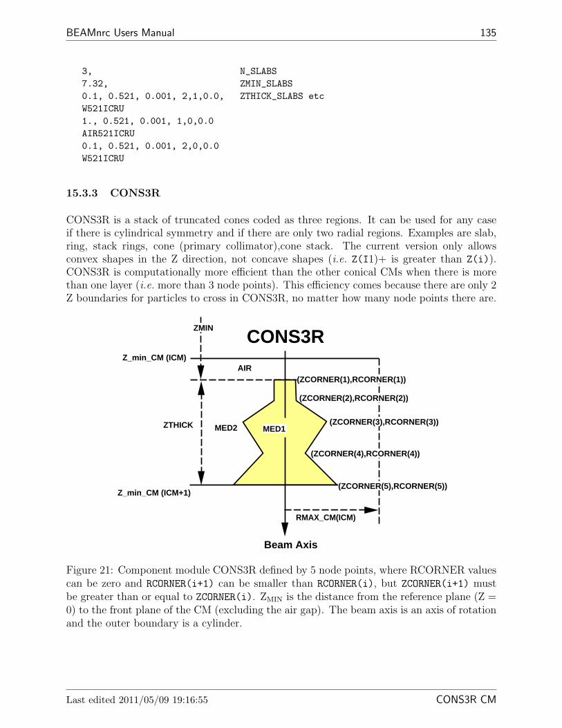
BEAMnrc Users Manual 135
3, N_SLABS7.32, ZMIN_SLABS0.1, 0.521, 0.001, 2,1,0.0, ZTHICK_SLABS etcW521ICRU1., 0.521, 0.001, 1,0,0.0AIR521ICRU0.1, 0.521, 0.001, 2,0,0.0W521ICRU
15.3.3 CONS3R
CONS3R is a stack of truncated cones coded as three regions. It can be used for any caseif there is cylindrical symmetry and if there are only two radial regions. Examples are slab,ring, stack rings, cone (primary collimator),cone stack. The current version only allowsconvex shapes in the Z direction, not concave shapes (i.e. Z(I1)+ is greater than Z(i)).CONS3R is computationally more efficient than the other conical CMs when there is morethan one layer (i.e. more than 3 node points). This efficiency comes because there are only 2Z boundaries for particles to cross in CONS3R, no matter how many node points there are.
Z_min_CM (ICM)
Z_min_CM (ICM+1)
AIR
RMAX_CM(ICM)
CONS3R
MED2 MED1
Beam Axis
ZMIN
(ZCORNER(1),RCORNER(1))
ZTHICK
(ZCORNER(2),RCORNER(2))
(ZCORNER(3),RCORNER(3))
(ZCORNER(4),RCORNER(4))
(ZCORNER(5),RCORNER(5))
Figure 21: Component module CONS3R defined by 5 node points, where RCORNER valuescan be zero and RCORNER(i+1) can be smaller than RCORNER(i), but ZCORNER(i+1) mustbe greater than or equal to ZCORNER(i). ZMIN is the distance from the reference plane (Z =0) to the front plane of the CM (excluding the air gap). The beam axis is an axis of rotationand the outer boundary is a cylinder.
Last edited 2011/05/09 19:16:55 CONS3R CM

136 NRCC Report PIRS-0509(A)revL
The input format for CONS3R, and an example of input file are given as follows.
CARDS CM_$CONS3R (CONS3R: Rev 1.10)**************
-1 Dummy line to indicate start of CM
0 RMAX_CM(ICM_$CONS3R) (F10.0): Outer radial boundary of CM (cm).
1 TITLE_$CONS3R (60A1): Title of CM.
2 ZMIN_$CONS3R (F15.0): Dist from front of cones toreference plane (Z=0).
3 ZTHICK_$CONS3R (F15.0): The thickness of cones (excludes front air).
4 NUM_NODE_$CONS3R (I5): The # of points to be used <$NPOINT_CONS3R.
Repeat 5 for I=1,NUM_NODE_$CONS3R
5 ZCORNER_$CONS3R(I), RCORNER_$CONS3R(I) (2F15.0):Positions (Z, R) for node I. First & last must matchZMIN_$CONS3R and ZMIN_$CONS3R+ZTHICK_$CONS3R. Note also therestriction Z(I+1) >= Z(I).
Repeat 6, 7 for inner (ie inside cons3r), then outer region
6 ECUT, PCUT, DOSE_ZONE, IREGION_TO_BIT, IREJCTIN (2F15.0,3I5):
ECUT, PCUT: Cutoff energies for electrons and photons.DOSE_ZONE: If non-zero, dose in this zone is scored in this
dose zoneIREGION_TO_BIT: region to LATCH bit correspondence for particles
interacting in this regionIREJCTIN: If IREJCT_GLOBAL is on, then by setting IREJCT=-1
here, range rejection is turned off in this regionIf left blank or zero, the global value is used.
7 MED_IN (24A1): Medium of regionused to set MED_INDEX.
Example*******
The following input example describes a 1cm thick flat-top cone, havinga radius at the top of 0.8cm and a radius at the bottom of 1.2cmsitting on a 0.3cm thick cylinder of radius 1.5cm which, in turn,is sitting atop a flat-top cone of thickness 1.0cm with top radius
15 COMPONENT MODULES CONS3R CM

BEAMnrc Users Manual 137
0.5cm and bottom radius=0.8cm. The two cones and cylinder aremade of H2O--note that all of these structures MUST be of the samemedium--and they are surrounded by AIR. Dose in the surroundingAIR is stored in dose zone 1, and dose in the cones/cylinderstructure is stored in zone 2.
5.0example cons3r0.02.360.0, 0.81.0, 1.21.0, 1.51.3, 1.51.3, 0.52.3, 0.80.521, 0.01, 2, 0, 0H2O0.521, 0.01, 1, 0 ,0AIR
Last edited 2011/05/09 19:16:55 CONS3R CM
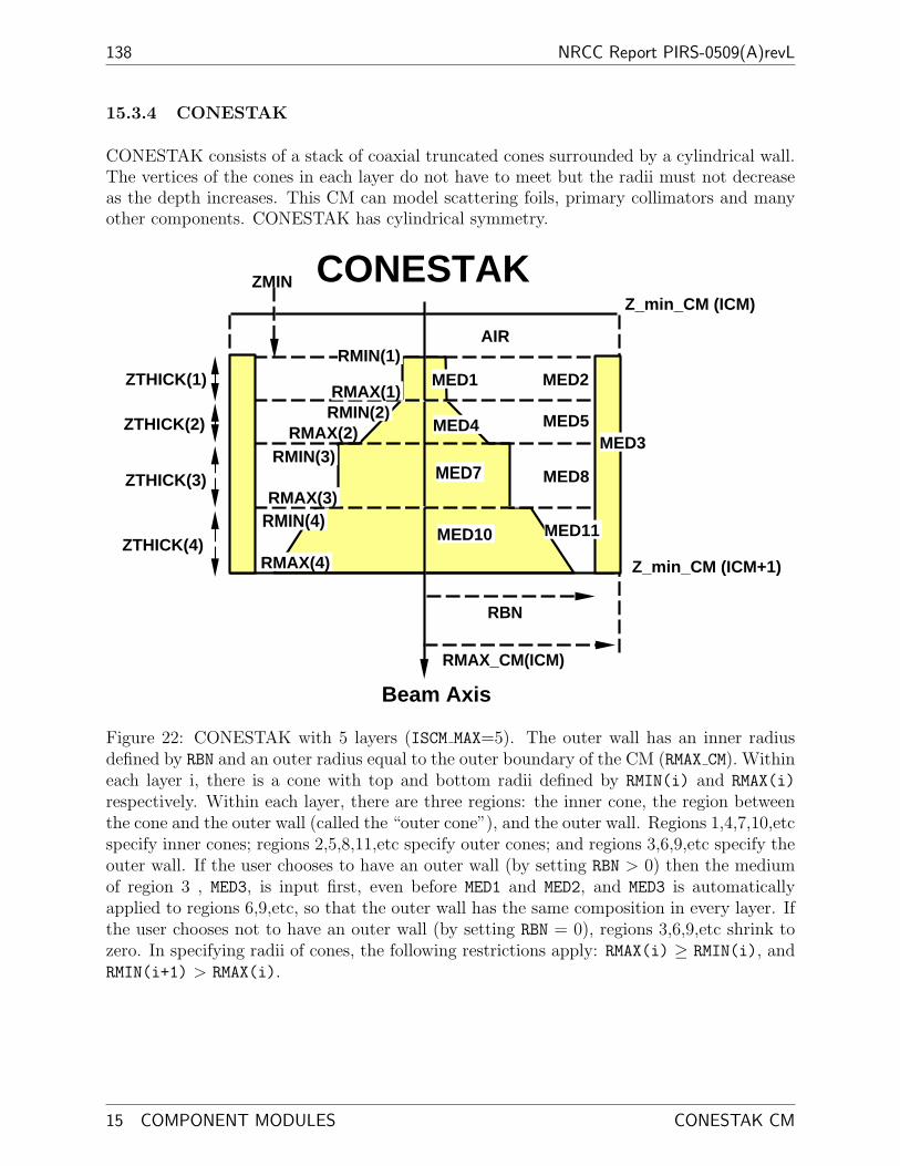
138 NRCC Report PIRS-0509(A)revL
15.3.4 CONESTAK
CONESTAK consists of a stack of coaxial truncated cones surrounded by a cylindrical wall.The vertices of the cones in each layer do not have to meet but the radii must not decreaseas the depth increases. This CM can model scattering foils, primary collimators and manyother components. CONESTAK has cylindrical symmetry.
Z_min_CM (ICM)
AIR
RMAX_CM(ICM)
CONESTAK
MED1 MED2
Beam Axis
MED4 MED5
MED7 MED8
MED10
MED3
RBN
Z_min_CM (ICM+1)
ZTHICK(1)
ZTHICK(2)
ZTHICK(3)
ZTHICK(4)
RMIN(1)
RMAX(1)RMIN(2)
RMAX(2)RMIN(3)
RMAX(3)RMIN(4)
RMAX(4)
ZMIN
MED11
Figure 22: CONESTAK with 5 layers (ISCM MAX=5). The outer wall has an inner radiusdefined by RBN and an outer radius equal to the outer boundary of the CM (RMAX CM). Withineach layer i, there is a cone with top and bottom radii defined by RMIN(i) and RMAX(i)
respectively. Within each layer, there are three regions: the inner cone, the region betweenthe cone and the outer wall (called the “outer cone”), and the outer wall. Regions 1,4,7,10,etcspecify inner cones; regions 2,5,8,11,etc specify outer cones; and regions 3,6,9,etc specify theouter wall. If the user chooses to have an outer wall (by setting RBN > 0) then the mediumof region 3 , MED3, is input first, even before MED1 and MED2, and MED3 is automaticallyapplied to regions 6,9,etc, so that the outer wall has the same composition in every layer. Ifthe user chooses not to have an outer wall (by setting RBN = 0), regions 3,6,9,etc shrink tozero. In specifying radii of cones, the following restrictions apply: RMAX(i) ≥ RMIN(i), andRMIN(i+1) > RMAX(i).
15 COMPONENT MODULES CONESTAK CM

BEAMnrc Users Manual 139
The input format for CONESTAK, and an example of input file are given as follows.
CARDS CM_$CONESTAK (CONESTAK Rev 1.8)********************************
-1 dummy line to indicate start of CM
0 RMAX_CM(ICM_$CONESTAK) (F10.0): Outer radial boundary (cm).
1 TITLE_$CONESTAK (60A1): Title of CM.
2 ZMIN_$CONESTAK, RBN_$CONESTAK (2F15.0):
ZMIN_$CONESTAK: Distance from front of first cone toreference plane (Z=0),
RBN_$CONESTAK: Inner radius of outer wall(Set to 0 if you do not want an outer wall)
3 ISCM_MAX_$CONESTAK (I5): Number of conical layers
Repeat 4 once for I=1,ISCM_MAX_$CONESTAK
4 ZTHICK_$CONESTAK(I), RMIN_$CONESTAK(I), RMAX_$CONESTAK(I) (3F15.0):
ZTHICK_$CONESTAK(I): Thickness of conical layer.RMIN_$CONESTAK(I): Front radius of conical layer.RMAX_$CONESTAK(I): Back radius of conical layer.
Note restrictions:RMAX_$CONESTAK(I)>=RMIN_$CONESTAK(I)RMIN_$CONESTAK(I+1)>=RMAX_$CONESTAK(I)
5 and 6 are only required if there is an outer wall (ie RBN_$CONESTAK~=0)
5 ECUT, PCUT, DOSE_ZONE, IREGION_TO_BIT in local region 3 (outer wall):(2F15.0,2I5)
ECUT, PCUT: Cutoff energies for electrons and photons.DOSE_ZONE: Dose scoring flag, non-zero to score dose
deposited in itIREGION_TO_BIT: Bit setting number for the region
6 MED_IN (24A1): Medium of local region 3used to set MED_INDEX.
Repeat 7-10 for each conical layer
7 ECUT, PCUT, DOSE_ZONE, IREGION_TO_BIT in local region 1 (inside cone):(2F15.0,2I5)
Last edited 2011/05/09 19:16:55 CONESTAK CM

140 NRCC Report PIRS-0509(A)revL
ECUT, PCUT: Cutoff energies for electrons and photons.DOSE_ZONE: Dose scoring flag, 0 to score dose deposited in itIREGION_TO_BIT: Bit setting number for the region
8 MED_IN (24A1): Medium of local region 1 (inside cone),used to set MED_INDEX
9 ECUT, PCUT, DOSE_ZONE, IREGION_TO_BIT in local region 2 (outside cone):(2F15.0,2I5)
ECUT, PCUT: Cutoff energies for electrons and photons.DOSE_ZONE: Dose scoring flag, 0 to score dose deposited in itIREGION_TO_BIT: Bit setting number for the region
10 MED_IN (24A1): Medium of local region 2 (outside of cone),used to set MED_INDEX
Example*******
The following input example describes two conical layers. The firstlayer is a flat-top cone 1.0cm thick, with a radius at the top of 0.8cmand a radius at the base of 1.2cm. The second layer is a cylinder, also1.0cm thick, of radius 1.2cm. The top cone is made of Cu and the bottomcylinder is made of Pb. The entire structure is encircled by a Pb wallwith inner radius 4cm and outer radius 5cm.In both layers, the medium between the cone and the outer wall is H2O.
Dose in the Cu cone will be scored in dose zone 1. Dose in the PB cylinderwill appear in dose zone 2. The dose to the encircling PB wall will be inzone 3. And the dose to the water in both layers will be scored in zone 4.ECUT and PCUT in all cases is 0.521MeV and 0.01MeV respectively.
5.0 RMAX_CMcone and cylinder surrounded by PB wall0.0, 4.021.0, 0.8, 1.21.0, 1.2, 1.20.521, 0.01, 3, 0PB0.521, 0.01, 1, 0CU0.521, 0.01, 4, 0H2O0.521, 0.01, 2, 0PB0.521, 0.01, 4, 0H2O
15 COMPONENT MODULES CONESTAK CM
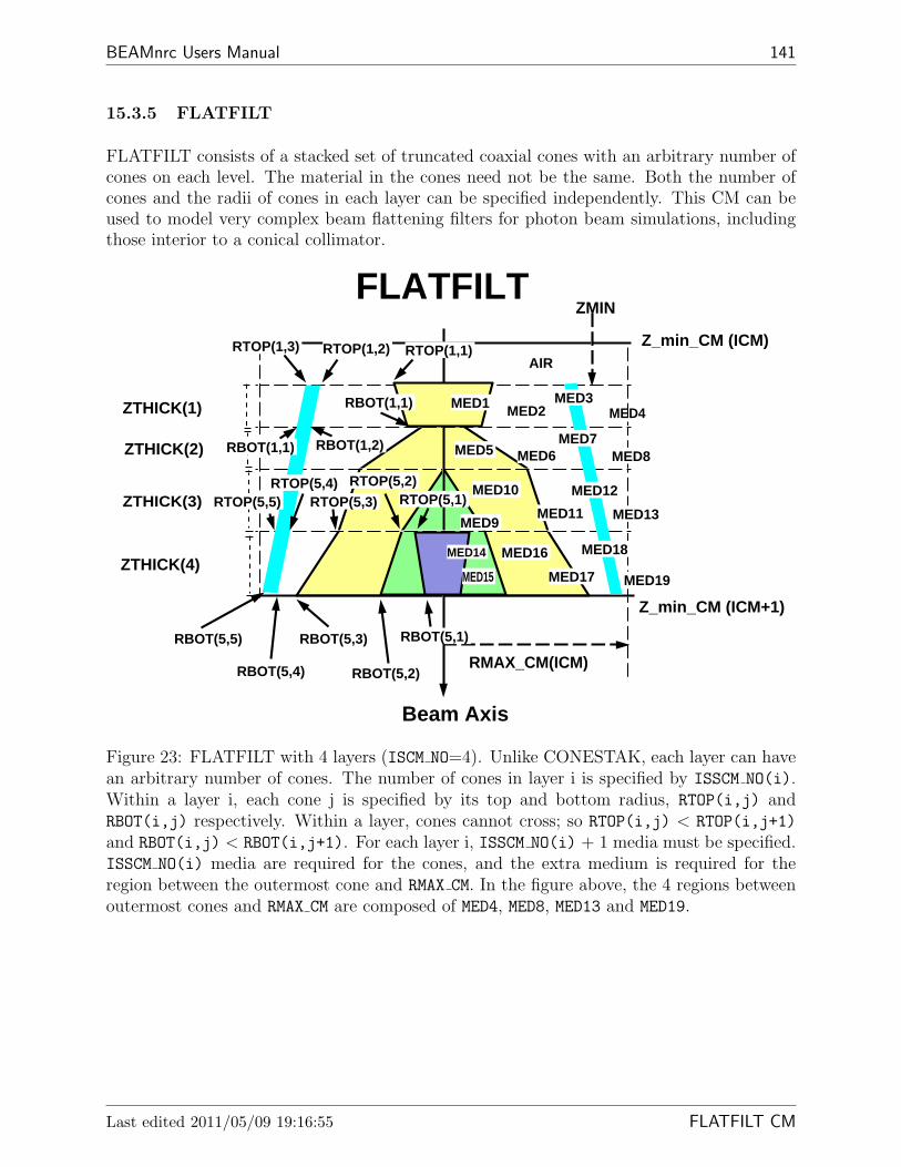
BEAMnrc Users Manual 141
15.3.5 FLATFILT
FLATFILT consists of a stacked set of truncated coaxial cones with an arbitrary number ofcones on each level. The material in the cones need not be the same. Both the number ofcones and the radii of cones in each layer can be specified independently. This CM can beused to model very complex beam flattening filters for photon beam simulations, includingthose interior to a conical collimator.
Z_min_CM (ICM)
Z_min_CM (ICM+1)
AIR
RMAX_CM(ICM)
Beam Axis
FLATFILT
MED1 MED2 MED4
MED5 MED6 MED8
MED9
MED10
MED11 MED13
MEDMED14
MED15
MED16
MED19
MED3
MED7
MED12
MED17
MED18
ZTHICK(1)
ZTHICK(2)
ZTHICK(3)
ZTHICK(4)
RTOP(1,1)RTOP(1,2)RTOP(1,3)
RBOT(1,1)
RBOT(1,2)RBOT(1,1)
RTOP(5,1)RTOP(5,2)
RTOP(5,3)RTOP(5,4)
RTOP(5,5)
RBOT(5,1)
RBOT(5,2)
RBOT(5,3)
RBOT(5,4)
RBOT(5,5)
ZMIN
Figure 23: FLATFILT with 4 layers (ISCM NO=4). Unlike CONESTAK, each layer can havean arbitrary number of cones. The number of cones in layer i is specified by ISSCM NO(i).Within a layer i, each cone j is specified by its top and bottom radius, RTOP(i,j) andRBOT(i,j) respectively. Within a layer, cones cannot cross; so RTOP(i,j) < RTOP(i,j+1)
and RBOT(i,j) < RBOT(i,j+1). For each layer i, ISSCM NO(i) + 1 media must be specified.ISSCM NO(i) media are required for the cones, and the extra medium is required for theregion between the outermost cone and RMAX CM. In the figure above, the 4 regions betweenoutermost cones and RMAX CM are composed of MED4, MED8, MED13 and MED19.
Last edited 2011/05/09 19:16:55 FLATFILT CM

142 NRCC Report PIRS-0509(A)revL
CARDS CM_$FLATFILT******************
-1 Dummy line to indicate start of CM.
0 RMAX_CM(ICM_$FLATFILT) (F10.0): Radius of outer boundary of CM (cm).
1 TITLE_$FLATFILT (60A1): Title of CM.
2 ZMIN_$FLATFILT (F10.0): Distance from front of CM (front ofthe first layer) to reference plane (Z=0),not including air gap.
3 ISCM_NO_$FLATFILT (I5): Number of layers.
Repeat 4-6 for I=1,ISCM_NO_$FLATFILT
4 ISSCM_NO_$FLATFILT(I), ZTHICK_$FLATFILT(I) (I5,F15.0):
ISSCM_NO_$FLATFILT(I): # cones in layer I(ex outer region).ZTHICK_$FLATFILT(I): Thickness of layer I.
Repeat 5 for J=1,ISSCM_NO_$FLATFILT(I) all on one line in orderof increasing cone radius.
5 RTOP_$FLATFILT(I,J) (F15.0):Top radius of cone J in layer I.Note restriction: RTOP_$FLATFILT(I,J+1)>RTOP_$FLATFILT(I,J)
Repeat 6 for J=1,ISSCM_NO_$FLATFILT(I) all on one line in orderof increasing cone radius.
6 RBOT_$FLATFILT(I,J) (F15.0):Bottom radius of cone J in layer I.Note restriction: RBOT_$FLATFILT(I,J+1)>RBOT_$FLATFILT(I,J)
Repeat 7 and 8 for J=1,ISSCM_NO_$FLATFILT(I)+1 for every layer I.When J=ISSCM_NO_$FLATFILT(I)+1, you are specifying ECUT, PCUT,MED_IN, etc. for the region between the outermost cone and RMAX_CMin layer I.
7 ECUT, PCUT, DOSE_ZONE, IREGION_TO_BIT (2F15.0,2I5):
ECUT, PCUT: Cutoff energies for electrons and photonsin cone J.
DOSE_ZONE: Dose scoring flag for cone J.IREGION_TO_BIT: Bit setting for region defined by cone J.
8 MED_IN (24A1): Medium of cone J
15 COMPONENT MODULES FLATFILT CM

BEAMnrc Users Manual 143
used to set MED_INDEX.
Example*******
The following example describes a FLATFILT with 2 layers. TheRMAX of this FLATFILT is 2cm. There is no air gap between thefirst layer and the top of the CM.
The first layer is 0.3 cm thick and comprises a convex cone madeof H2O within a concave cone made of PB. The convex H2O cone hasa top radius of 0.0cm and a bottom radius of 1.0cm. The concave PBcone has a top radius of 1.5cm and a bottom radius of 1.1cm.The region between the outer, concave cone and RMAX_CM is AIR.The second layer is also 0.3 cm thick and comprises a singlecylinder of H2O having radius 1cm (ie top radius=bottomradius=1cm). The region between the outer boundary of thiscylinder and RMAX_CM (an annular region) is AIR.
The dose to the AIR regions is scored in dose zone 1. The doseto H2O regions (the convex cone in the first layer and the cylinderin the second layer) is scored in zone 2. And the dose to PB(the concave cone in the first layer) is scored in zone 3.ECUT and PCUT for all regions are 0.521 MeV and 0.01 MeVrespectively.
2.00000, RMAX_CMflatfilt0.0, ZMIN of first layer2, no. of layers2, 0.30, no. of cones in first layer and thickness0.0,1.5, top radii of cones1.0,1.1, bottom radii of cones1, 0.3 no. of cones in second layer and thickness1.0 top radius of cone1.0 bottom radius of cone0.521, 0.01, 2, 0, ECUT, PCUT, DOSE_ZONE, IREGION_TO_BITH2O MEDIUM -- for layer 1, cone 10.521, 0.01, 3, 0PB -- for layer 1, cone 20.521, 0.01, 1, 0AIR -- for region between cone 2 and RMAX0.521, 0.01, 2, 0H2O -- for layer 2, cone 10.521, 0.01, 1, 0AIR -- for region between cone 1 and RMAX
Last edited 2011/05/09 19:16:55 CHAMBER CM

144 NRCC Report PIRS-0509(A)revL
15.3.6 CHAMBER
CHAMBER models a parallel-plate ion chamber in a container with top and bottom planesof arbitrary thickness and material. CHAMBER also models a combination of scatteringfoils, cylindrical collimators and an ion chamber, etc.. This CM is also useful for central-axisdepth-dose calculations and for analysis of dose components due to particles coming fromdifferent parts of an accelerator. CHAMBER has cylindrical symmetry.
Z_min_CM (ICM)
AIR
RMAX_CM(ICM)
Beam Axis
ZMINCHAMBER
MED2 (AIR)
MED4 (AIR)
Top Part
Bottom Part
Central Part
Z_min_CM (ICM+1)
MED1
MED3
MED5)
MED9 MED10MED11 MED12
MED14MED15
MED6
MED7 (AIR)
MED13MED16
MED8
RCYS(1,1)
RCYS(1,2)
RCYS(1,3)
RCYS(2,1)
RCYS(3,1)
RCYS(4,1)
RCYS(5,1)
Z(1)Z(2)
Z(3)Z(4)
Z(5)Z(6)
Z(7)
Z(9)
layer #
1
2
3
4
5
67
89
chamberwallgap
containerwall
Figure 24: CHAMBER component module for an ionization chamber or any symmetriccylindrical-planar geometries. The CM shown consists of three parts: top, central(chamber),and bottom. The top and bottom parts each have 2 layers (N TOP = N BOT=2), and thechamber part has 5 layers (N CHM=5). In general, the central part is required while the topand bottom parts are not. Each layer in both top and bottom parts is divided into an innercylinder and an outer annulus. For a layer i in the top part, the outer radius of the cylinder(inner radius of the annulus) is given by RCYS(i+1,1), and the outer radius of the annulusis RMAX CM. For a layer j in the bottom part, the outer radius of the cylinder is given byRCYS(j+N TOP+1,1), and outer radius of the annulus is RMAX CM. Within the top or bottompart, layers can have different RCYS and media; however, input for the top or bottom part issimplified if all layers within that part have the same RCYS, the same medium in the innercylinders, and the same medium in the outer annuli. In the central part, all layers havethe same outer radius, RCYS(1,1), which also defines the inner radius of the chamber wall.The outer radius of the chamber wall is given by RCYS(1,2), which, in turn, is the innerradius of the gap between the chamber wall and the container wall. The gap has outer radiusRCYS(1,3), which is also the inner radius of the container wall. The container wall has outerradius RMAX CM.
15 COMPONENT MODULES CHAMBER CM

BEAMnrc Users Manual 145
Back previousCM
Back of CM
Rmax
Beam Axis
CHAMBER as phantom
Chamber Wall
Gap
Container Wall
Central Part
do
se z
on
es
Figure 25: CHAMBER as a depth-dose phantom. Only the central (chamber) part of theCM is used. The layers within this part become the depth-dose zones, and, hence, all layersare composed of the same material (the phantom material). Depth resolution is determinedby the number of layers. If all layers have the same thickness, then the input can be mademore efficient by inputting the number of layers on the same line as the layer thickness,ZTHICK. Then you only have to input ECUT, PCUT, DOSE ZONE and MED once for all layers.If DOSE ZONE >0, the input value will be used for the first layer and then DOSE ZONE willbe incremented by 1 automatically for each subsequent layer. Alternatively, if there areN separate groups of layers, where the layers in each group have equal thickness, you canset N CHM $CHAMBER = -N. For each of the N groups of layers, you must specify the layerthickness and the number of layers in the group. Following this, you only have to specifyECUT, PCUT, DOSE ZONE and MED once for all layers, similar to the case where ALL layersare of equal thickness. Note that all depth-dose zones have the same radius, determined byRCYS(1,1). A small RCYS(1,1) determines the depth-dose on the beam axis, while a largerRCYS(1,1) includes dose deposited further away from the beam axis. If the phantom extendsbeyond the radius of the dose zones, then the chamber wall, gap, and container wall canbe composed of the same phantom material. This set-up can be very efficient for centralaxis depth-dose calculations when used in conjunction with range rejection because the largevolume in the chamber wall leads to effective range rejection. However, it has been observedfor electron beams that the lack of z boundaries in the wall region can lead to small step sizeeffects. This effect can be minimised by decreasing ESTEPE (see section 11.4).
Last edited 2011/05/09 19:16:55 CHAMBER CM

146 NRCC Report PIRS-0509(A)revL
CARDS CM_$CHAMBER****************
-1 Dummy line to indicate start of CM.
0 RMAX_CM(ICM_$CHAMBER):( F10.0): Maximum radius of component module
1 TITLE_$CHAMBER (60A1): Title of CM.
2 ZMIN_$CHAMBER (F15.0): Distance from front surface of 1st cylinder toreference plane (Z=0). Excludes any air gap.
3 N_TOP_$CHAMBER, N_CHM_$CHAMBER, N_BOT_$CHAMBER (3I5)
N_TOP_$CHAMBER: Number of layers in top part (>= 0).N_CHM_$CHAMBER: Number of layers in chamber itself (> 0 to input
chamber layers individually or if ALL layers havethe same thickness and medium; < 0 toinput -N_CHM_$CHAMBER groups of layers wherelayers in each group have the same thickness andALL layers have the same MED).
N_BOT_$CHAMBER: Number of layers in bottom part (>= 0).==========================================================================4 Inputs for the top part (If N_TOP_$CHAMBER >0):==========================================================================
If all layers in this part are identical, then in line (a) includeNFLAG=N_TOP_$CHAMBER, otherwise repeat (a) to (e) for each of thelayers.
a) ZTHICK, RCYS_$CHAMBER , NFLAG (2F15.0,I5)ZTHICK (F15.0): Thickness of each layer in top partRCYS_$CHAMBER (F15.0): Radius of inner cylinders in each layerN_TOP_$CHAMBER (I5): Number of layers in top part
b) ECUT,PCUT,DOSE_ZONE,IREGION_TO_BIT for inner cylinders(2F15.0,2I5,1-line):
ECUT, PCUT: Cutoff energies for electrons and photons.DOSE_ZONE: Dose scoring region for this region, 0=>no dose scored.IREGION_TO_BIT : Bit # in LATCH designated to this region
c) MED_IN (24A1): Medium of inner cylinder (used for MED_INDEX)
d) ECUT,PCUT,DOSE_ZONE,IREGION_TO_BIT for outer annuli(2F15.0,2I5,1-line):
e) MED_IN (24A1): Medium for outer annuli (used for MED_INDEX)
=========================================================================
15 COMPONENT MODULES CHAMBER CM
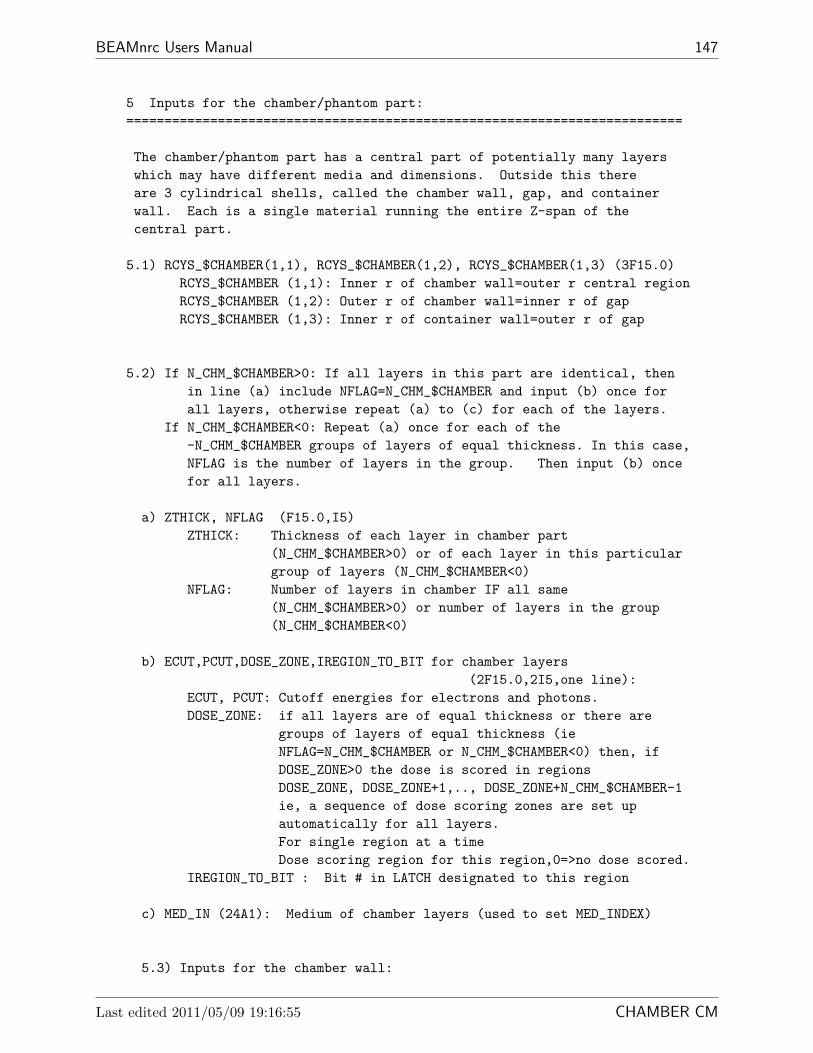
BEAMnrc Users Manual 147
5 Inputs for the chamber/phantom part:=========================================================================
The chamber/phantom part has a central part of potentially many layerswhich may have different media and dimensions. Outside this thereare 3 cylindrical shells, called the chamber wall, gap, and containerwall. Each is a single material running the entire Z-span of thecentral part.
5.1) RCYS_$CHAMBER(1,1), RCYS_$CHAMBER(1,2), RCYS_$CHAMBER(1,3) (3F15.0)RCYS_$CHAMBER (1,1): Inner r of chamber wall=outer r central regionRCYS_$CHAMBER (1,2): Outer r of chamber wall=inner r of gapRCYS_$CHAMBER (1,3): Inner r of container wall=outer r of gap
5.2) If N_CHM_$CHAMBER>0: If all layers in this part are identical, thenin line (a) include NFLAG=N_CHM_$CHAMBER and input (b) once forall layers, otherwise repeat (a) to (c) for each of the layers.
If N_CHM_$CHAMBER<0: Repeat (a) once for each of the-N_CHM_$CHAMBER groups of layers of equal thickness. In this case,NFLAG is the number of layers in the group. Then input (b) oncefor all layers.
a) ZTHICK, NFLAG (F15.0,I5)ZTHICK: Thickness of each layer in chamber part
(N_CHM_$CHAMBER>0) or of each layer in this particulargroup of layers (N_CHM_$CHAMBER<0)
NFLAG: Number of layers in chamber IF all same(N_CHM_$CHAMBER>0) or number of layers in the group(N_CHM_$CHAMBER<0)
b) ECUT,PCUT,DOSE_ZONE,IREGION_TO_BIT for chamber layers(2F15.0,2I5,one line):
ECUT, PCUT: Cutoff energies for electrons and photons.DOSE_ZONE: if all layers are of equal thickness or there are
groups of layers of equal thickness (ieNFLAG=N_CHM_$CHAMBER or N_CHM_$CHAMBER<0) then, ifDOSE_ZONE>0 the dose is scored in regionsDOSE_ZONE, DOSE_ZONE+1,.., DOSE_ZONE+N_CHM_$CHAMBER-1ie, a sequence of dose scoring zones are set upautomatically for all layers.For single region at a timeDose scoring region for this region,0=>no dose scored.
IREGION_TO_BIT : Bit # in LATCH designated to this region
c) MED_IN (24A1): Medium of chamber layers (used to set MED_INDEX)
5.3) Inputs for the chamber wall:
Last edited 2011/05/09 19:16:55 CHAMBER CM
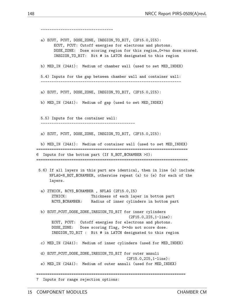
148 NRCC Report PIRS-0509(A)revL
---------------------------------
a) ECUT, PCUT, DOSE_ZONE, IREGION_TO_BIT, (2F15.0,2I5):ECUT, PCUT: Cutoff energies for electrons and photons.DOSE_ZONE: Dose scoring region for this region,0=>no dose scored.IREGION_TO_BIT: Bit # in LATCH designated to this region
b) MED_IN (24A1): Medium of chamber wall (used to set MED_INDEX)
5.4) Inputs for the gap between chamber wall and container wall:----------------------------------------------------------------
a) ECUT, PCUT, DOSE_ZONE, IREGION_TO_BIT, (2F15.0,2I5):
b) MED_IN (24A1): Medium of gap (used to set MED_INDEX)
5.5) Inputs for the container wall:-------------------------------------------
a) ECUT, PCUT, DOSE_ZONE, IREGION_TO_BIT, (2F15.0,2I5):
b) MED_IN (24A1): Medium of container wall (used to set MED_INDEX)=====================================================================6 Inputs for the bottom part (If N_BOT_$CHAMBER >0):=====================================================================
5.6) If all layers in this part are identical, then in line (a) includeNFLAG=N_BOT_$CHAMBER, otherwise repeat (a) to (e) for each of thelayers.
a) ZTHICK, RCYS_$CHAMBER , NFLAG (2F15.0,I5)ZTHICK: Thickness of each layer in bottom partRCYS_$CHAMBER: Radius of inner cylinders in bottom part
b) ECUT,PCUT,DOSE_ZONE,IREGION_TO_BIT for inner cylinders(2F15.0,2I5,1-line):
ECUT, PCUT: Cutoff energies for electrons and photons.DOSE_ZONE: Dose scoring flag, 0=>do not score dose.IREGION_TO_BIT : Bit # in LATCH designated to this region
c) MED_IN (24A1): Medium of inner cylinders (used for MED_INDEX)
d) ECUT,PCUT,DOSE_ZONE,IREGION_TO_BIT for outer annuli(2F15.0,2I5,1-line):
e) MED_IN (24A1): Medium of outer annuli (used for MED_INDEX)
====================================================================7 Inputs for range rejection options:
15 COMPONENT MODULES CHAMBER CM

BEAMnrc Users Manual 149
====================================================================
MRNGE (I5) 0 or 1
MRNGE : = 1 to estimate thickness of the CHAMBER forECUTRR calculations in automated range rejection(IREJCT_GLOBAL=1) (crude approx for 5 layers)
= 0 no ECUTRR calculation--range rejection willstill be done on a region-by-region basis
Note that MRNGE only has an effect if automated rangerejection is on (IREJCT_GLOBAL=1).
Example*******
The following set of cards defines a chamber with 2 top layers, 3 chamberlayers, and 2 bottom layers.The chamber wall is AL & the chamber container is CU. The detectingmaterial is air.The air cavities are assigned as dose region 1 and the rest as region 2.
10.5; radius of CMChamber with 2 top layers, 3 chamber layers, 2 bottom layers10.0; distance from front surface of the CM to the reference plane (z=0)2,3,2; 2 top layers, 3 chamber layers, 2 bottom layers0.1,5.0,0; first layer in the top part, 0.1cm thick, IR=5cm0.521,0.010,2,2; dose region # = 2CU ; medium0.521,0.010,2,2;CU0.2,5.0,0; second layer is 0.2 cm thick, radius = 5.0 cm0.521,0.010,2,2; for inner cylinder (dose region # = 2)AL0.521,0.010,2,2; for outer annulusAL5.0,5.2,10.0; IR & OR of chamber wall, IR of container0.2; thickness of the first layer (air) in chamber part0.521,0.010,1,2; dose region # = 1AIR0.1; thickness of the second layer (AL) in chamber part0.521,0.010,2,2; dose region # = 2AL0.2; thickness of the third layer (air) in chamber part0.521,0.010,1,2; dose region # = 1AIR0.521,0.010,2,2; chamber wall (dose region # = 2)AL0.521,0.010,2,2; air gap betweem chamber wall and container wall
Last edited 2011/05/09 19:16:55 CHAMBER CM

150 NRCC Report PIRS-0509(A)revL
AIR0.521,0.010,2,2; chamber containerCU0.1,5.0,2; 2 layers in bot. part have = thickness, IR0.521,0.010,2,2; for inner cylindersAL0.521,0.010,2,2; for outer annuliAL0; do not calculate ECUTRR
15 COMPONENT MODULES CHAMBER CM

BEAMnrc Users Manual 151
15.3.7 JAWS
JAWS is used for a set of paired bars, which can be bars in the collimator or applicator. Thebars are of arbitrary thickness and material, and X or Y orientation. The outer boundary ofJAWS has square symmetry but the jaws themselves can be very asymmetric. The input forJAWS can be tedious but the GUI has a feature which will automatically set the X and Yvalues to give an arbitrary on-axis rectangular photon beam field size at a given SSD basedon tracing back to an arbitrary focus located on the central axis.
JAWSZ_min_CM (ICM)
Z_min_CM (ICM+1)
MED1 JAW 1(X JAW)
AIR
JAW 2(Y JAW)
ZMAX(1)
ZMIN(1) ZMIN(2)
ZMAX(2)
RMAX_CM(ICM)
XFN(1)XFP(1)
XBN(1)XBP(1)
MED1
AIR
Beam Axis
(TOP VIEW)
X JAW
Y JAW
RMAX_CM
MED2
MED2
MED1
Y
XMED1
Figure 26: JAWS component module with paired X and Y jaws (ISCM MAX=2). The cutawayview cuts right through the opening in the Y jaws, hence the representation of the Y jaws asa dashed rectangle. For a set of jaws i, the front opening of the jaws is specified by XFP(i)
and XFN(i). The back opening is specified by XBP(i) and XBN(i). These coordinates arenot shown for the Y jaws, however they are evident in the top view. The inside jaw surfacesare 2 planes, one connecting XFP(i) to XBP(i) and the other connecting XFN(i) to XBN(i)
X jaws and openings between X jaws extend to ± RMAX CM in the Y-direction; Y jaws andopenings extend to ± RMAX CM in the X direction. There must be a gap of at least 0.01cm between the first set of jaws and the top of the CM (i.e. ZMIN(1)-ZMIN CM ≥ 0.01)and between sets of jaws (i.e. ZMIN(i)-ZMAX(i-1) ≥ 0.01). Materials in each layer can bedifferent but opposite jaws must be the same material.
Last edited 2011/05/09 19:16:55 JAWS CM

152 NRCC Report PIRS-0509(A)revL
The input format for JAWS, and an example of input file are given as follows.
CARDS CM_$JAWS(JAWS: Rev 1.8)**************
-1 dummy line read in main used to separate input for CMs
0 RMAX_CM(ICM_JAWS) (F10.0):Perpendicular distance from Z-axis to boundarysurrounding component module. This componentmodule has a square boundary.
1 TITLE_$JAWS (60A1): Title of CM.
2 ISCM_MAX_$JAWS (I5): Number of paired bars or jaws in CM.
Repeat 3 and 4 for I=1,ISCM_MAX_$JAWS
3 XY_CHOICE (A1): indicate orientation of the paired bars/jawsX means bars/jaws perpendicular to x axis
i.e. separation and movement is along x-axis
4 ZMIN_$JAWS(I), ZMAX_$JAWS(I), XFP_$JAWS(I), XBP_$JAWS(I),XFN_$JAWS(I), XBN_$JAWS(I) (6F15.0)
ZMIN_$JAWS(I): Distance front of bars/jaws to reference plane.ZMAX_$JAWS(I): Distance back of bars/jaws to reference plane.XFP_$JAWS(I): positive bar/jaw x or y coodinate at front.XBP_$JAWS(I): positive bar/jaw x or y coodinate at back.XFN_$JAWS(I): negative bar/jaw x or y coodinate at front.XBN_$JAWS(I): negative bar/jaw x or y coodinate at back.
5 ECUT, PCUT, DOSE_ZONE, IREGION_to_BIT (2F15.0,2I5): for interior(assumed to be AIR)
ECUT, PCUT: Cutoff energies for electrons and photons.DOSE_ZONE: Dose scoring zone of air surrounding bars.IREGION_TO_BIT: This region associated with this bit in LATCH
Repeat 6 and 7 for I=1,ISCM_MAX_$JAWS
6 ECUT, PCUT, DOSE_ZONE, IREGION_TO_BIT (2F15.0,2I5)
ECUT, PCUT: Cutoff energies for electrons and photons injaw I.
DOSE_ZONE: Dose scoring zone for jaw I.IREGION_TO_BIT: Both bars of jaw I associated with this bit.
7 MED_IN (24A1): Medium of jaw I, used to set MED_INDEX.
15 COMPONENT MODULES JAWS CM

BEAMnrc Users Manual 153
Example*******
The following set of cards defines a pair of 5 cm-thick Al jaws.The first set of bars open along the X axis. The inside faces ofthis jaw are vertical at |X|=3cm. The second set of bars open alongthe Y axis. The insidefaces of this jaw are angled out slightly, beginning at |Y|=3cm at the topof the jaw and ending at |Y|=3.05cm at the bottom of the jaw.The first jaw starts at Z=30.0 cm. Note the 0.01 cm airgap betweenthe two jaws.
Electrons will be followed in the CM down to kinetic energies of10 keV (total energies of 0.521 MeV) and photons will be followed downto energies of 1 keV. The dose deposited in the air will be scored andadded to the dose deposited in the bars in dose zone 1.
15.0 RMAX_CMJAWS: 2 Al jaws, 5cm thick2X30.0, 35.0, 3.0, 3.0, -3.0, -3.0Y35.01, 40.01, 3.0, 3.05, -3.0, -3.050.0, 0.0, 1, 00.0, 0.0, 1, 0AL0.0, 0.0, 1, 0AL
Last edited 2011/05/09 19:16:55 JAWS CM

154 NRCC Report PIRS-0509(A)revL
15.3.8 DYNJAWS
DYNJAWS is a version of JAWS (see Section 15.3.7 above) which allows the user to specifychanging jaw settings (Z positions and opening coordinates) over the course of a simula-tion. There are two dynamic modes: “step-and-shoot” (MODE $DYNJAWS=2) and “dynamic”(MODE $DYNJAWS=1). If being run in one of these modes, then the user must specify the jawsettings in a separate file. The format of this file is:
NFIELD
FOR I=1,NFIELD[
INDEX(I)
FOR J=1,ISCM_MAX[
ZMIN(J,I),ZMAX(J,I),XFP(J,I),XBP(J,I),XFN(J,I),XBN(J,I)
]
]
where:
NFIELD = the number of “sets” of jaw settings, or fields.
INDEX(I) = the index of field I, where 0≤INDEX(I)≤1 and INDEX(I)>INDEX(I-1).
ISCM MAX = the number of jaws.
ZMIN(J,I) = the Z position of the front of jaw J for field I.
ZMAX(J,I) = the Z position of the back of jaw J for field I.
XFP(J,I) = the front X or Y coordinate (depending on jaw orientation) of the positive barof jaw J for field I.
XBP(J,I) = the back X or Y coordinate of the positive bar of jaw J for field I.
XFN(J,I) = the front X or Y coordinate of the negative bar of jaw J for field I.
XBN(J,I) = the back X or Y coordinate of the negative bar of jaw J for field I.
The parameter, INDEX(I), is used to determine which field is used for a given primaryhistory simulated. At the beginning of each primary history a random number, RND, on [0,1]is chosen and compared to the INDEX(I). The field no. used is the lowest value of I forwhich RND≤INDEX(I). If the user has selected “step-and-shoot” mode, then the jaw settingsfor field I are simply used. If the user has selected “dynamic” mode, then the jaw settingsare a linear interpolation between field I-1 and I based on the value of RND. For example,the Z position of the front of jaw J, ZMIN(J), would be given by:
ZMIN (J) = ZMIN (J, I− 1) +[ZMIN (J, I)− ZMIN (J, I− 1)]
[INDEX (I)− INDEX (I− 1)]× [RND− INDEX (I− 1)] (6)
In this way, the “dynamic” mode simulates jaw motion while the beam is on.
15 COMPONENT MODULES DYNJAWS CM
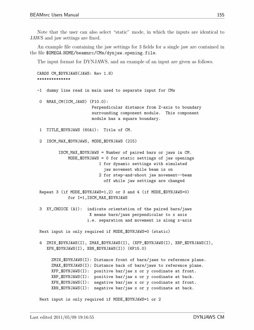
BEAMnrc Users Manual 155
Note that the user can also select “static” mode, in which the inputs are identical toJAWS and jaw settings are fixed.
An example file containing the jaw settings for 3 fields for a single jaw are contained inthe file $OMEGA HOME/beamnrc/CMs/dynjaw.opening.file.
The input format for DYNJAWS, and an example of an input are given as follows.
CARDS CM_$DYNJAWS(JAWS: Rev 1.8)**************
-1 dummy line read in main used to separate input for CMs
0 RMAX_CM(ICM_JAWS) (F10.0):Perpendicular distance from Z-axis to boundarysurrounding component module. This componentmodule has a square boundary.
1 TITLE_$DYNJAWS (60A1): Title of CM.
2 ISCM_MAX_$DYNJAWS, MODE_$DYNJAWS (2I5)
ISCM_MAX_$DYNJAWS = Number of paired bars or jaws in CM.MODE_$DYNJAWS = 0 for static settings of jaw openings
1 for dynamic settings with simulatedjaw movement while beam is on
2 for step-and-shoot jaw movement--beamoff while jaw settings are changed
Repeat 3 (if MODE_$DYNJAWS=1,2) or 3 and 4 (if MODE_$DYNJAWS=0)for I=1,ISCM_MAX_$DYNJAWS
3 XY_CHOICE (A1): indicate orientation of the paired bars/jawsX means bars/jaws perpendicular to x axis
i.e. separation and movement is along x-axis
Next input is only required if MODE_$DYNJAWS=0 (static)
4 ZMIN_$DYNJAWS(I), ZMAX_$DYNJAWS(I), (XFP_$DYNJAWS(I), XBP_$DYNJAWS(I),XFN_$DYNJAWS(I), XBN_$DYNJAWS(I)) (6F15.0)
ZMIN_$DYNJAWS(I): Distance front of bars/jaws to reference plane.ZMAX_$DYNJAWS(I): Distance back of bars/jaws to reference plane.XFP_$DYNJAWS(I): positive bar/jaw x or y coodinate at front.XBP_$DYNJAWS(I): positive bar/jaw x or y coodinate at back.XFN_$DYNJAWS(I): negative bar/jaw x or y coodinate at front.XBN_$DYNJAWS(I): negative bar/jaw x or y coodinate at back.
Next input is only required if MODE_$DYNJAWS=1 or 2
Last edited 2011/05/09 19:16:55 DYNJAWS CM
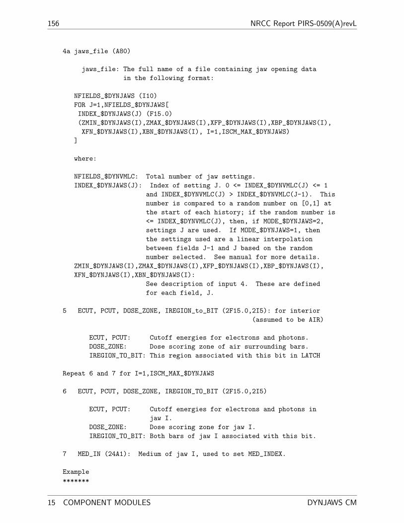
156 NRCC Report PIRS-0509(A)revL
4a jaws_file (A80)
jaws_file: The full name of a file containing jaw opening datain the following format:
NFIELDS_$DYNJAWS (I10)FOR J=1,NFIELDS_$DYNJAWS[INDEX_$DYNJAWS(J) (F15.0)(ZMIN_$DYNJAWS(I),ZMAX_$DYNJAWS(I),XFP_$DYNJAWS(I),XBP_$DYNJAWS(I),XFN_$DYNJAWS(I),XBN_$DYNJAWS(I), I=1,ISCM_MAX_$DYNJAWS)
]
where:
NFIELDS_$DYNVMLC: Total number of jaw settings.INDEX_$DYNJAWS(J): Index of setting J. 0 <= INDEX_$DYNVMLC(J) <= 1
and INDEX_$DYNVMLC(J) > INDEX_$DYNVMLC(J-1). Thisnumber is compared to a random number on [0,1] atthe start of each history; if the random number is<= INDEX_$DYNVMLC(J), then, if MODE_$DYNJAWS=2,settings J are used. If MODE_$DYNJAWS=1, thenthe settings used are a linear interpolationbetween fields J-1 and J based on the randomnumber selected. See manual for more details.
ZMIN_$DYNJAWS(I),ZMAX_$DYNJAWS(I),XFP_$DYNJAWS(I),XBP_$DYNJAWS(I),XFN_$DYNJAWS(I),XBN_$DYNJAWS(I):
See description of input 4. These are definedfor each field, J.
5 ECUT, PCUT, DOSE_ZONE, IREGION_to_BIT (2F15.0,2I5): for interior(assumed to be AIR)
ECUT, PCUT: Cutoff energies for electrons and photons.DOSE_ZONE: Dose scoring zone of air surrounding bars.IREGION_TO_BIT: This region associated with this bit in LATCH
Repeat 6 and 7 for I=1,ISCM_MAX_$DYNJAWS
6 ECUT, PCUT, DOSE_ZONE, IREGION_TO_BIT (2F15.0,2I5)
ECUT, PCUT: Cutoff energies for electrons and photons injaw I.
DOSE_ZONE: Dose scoring zone for jaw I.IREGION_TO_BIT: Both bars of jaw I associated with this bit.
7 MED_IN (24A1): Medium of jaw I, used to set MED_INDEX.
Example*******
15 COMPONENT MODULES DYNJAWS CM

BEAMnrc Users Manual 157
The following input defines a single tungsten jaw oriented in the Ydirection operating in step-and-shoot (MODE_$DYNJAWS=2) mode.The jaw settings (Z position, opening coordinates) are definedin the file $OMEGA_HOME/beamnrc/CMs/dynjaw.opening.file(included with the distribution).
40.0, RMAXCM #7: jaws set for a 10x10cm field at SSD=100 cm1,2, # PAIRED BARS OR JAWS, MODEY$OMEGA_HOME/beamnrc/CMs/dynjaw.opening.file0.7, 0.01, 0, 21,0.7, 0.01, 0, 13,W700ICRU
Last edited 2011/05/09 19:16:55 DYNJAWS CM

158 NRCC Report PIRS-0509(A)revL
15.3.9 APPLICAT
APPLICAT is used for a set of rectangular scrapers. Each scraper is defined by the outerregion of two concentric rectangles, the inner region being air. The scrapers are of arbitrarythickness, width in both X and Y directions, and position relative to the reference plane(Z = 0). The scrapers can be of different materials. This CM may be used for modellingthe square applicator found in electron beams although it does not allow for a bevelled edge.The outer boundary of APPLICAT is a square centered on the beam axis.
APPLICAT Z_min_CM (ICM)
Z_min_CM (ICM+1)
AIR
ZMIN(1) ZMIN(2)
RMAX_CM(ICM)
Beam Axis
AIR
XMIN(1)WIDTHX(1)
XMIN(2)WIDTHX(2)
ZBACK
MED1MED1
MED2MED2ZTHICK(2)
ZTHICK(1)
(TOP VIEW)
RMAX_CM
Beam AxisMED2
Y
XMED1
Figure 27: An APPLICAT with 2 scrapers (N=2). Each scraper i has a rectangular openingin the centre with half-width in the X-direction XMIN(i) and half-width in the Y-directionYMIN(i) . The width of scraper i in the X-direction is given by WIDTHX(i) and in the Y-direction by WIDTHY(i). The cross section does not show the Y dimensions of the scrapers,however the Y dimensions are evident in the top view. The minimum space between twoscraper is 0.01 cm of air. There is also a minimum 0.01 cm air gap at the front (ie betweenZ min CM(1) and ZMIN(1)) and back (i.e. between ZBACK and the back of the last scraper)of the CM.
15 COMPONENT MODULES APPLICAT CM

BEAMnrc Users Manual 159
The input format for APPLICAT, and an example of input file are given as follows.
CARDS CM_APPLICAT*****************
-1 Dummy line to indicate start of CM.
0 RMAX_CM(ICM_$APPLICAT) (F10.0): Half-width of outer boundary of CM (cm).
1 TITLE_$APPLICAT (60A1): Title of CM.
2 ZBACK_$APPLICAT (F15.0): Z of back face of the CM(air will be added if necessary below thelast applicator)
Note that there is always an air gap (thickness =AIRGAPMIN) in the front and the back of this CM.Therefore ZBACK_$APPLICAT should be >= Z of the back face of thelast scraper + AIRGAPMIN.
3 N_$APPLICAT, ISHAPE (2I5):N_$APPLICAT: Number of scrapers in the CM.ISHAPE: Index of applicators’ shape, default to square, 1 for
rectangle.
Repeat 4 for I=1,N_$APPLICAT.
4 ZMIN_$APPLICAT(I), ZTHICK_$APPLICAT(I), XMIN_$APPLICAT(I),YMIN_$APPLICAT(I),WIDTHX_$APPLICAT(I), WIDTHY_$APPLICAT(I),DOSE_ZONE,IREGION_TO_BIT (6F15.0,2I4):
ZMIN_$APPLICAT(I): Z of front face of scraper I.Note that ZMIN_$APPLICAT(1)-Z_min_CM must be >= AIRGAPMIN.
ZTHICK_$APPLICAT(I): Thickness of scraper I. Note thatZMIN_$APPLICAT(I+1)-(ZMIN_$APPLICAT(I)+ZTHICK_$APPLICAT(I))must be >= AIRGAPMIN.
XMIN_$APPLICAT(I): (ISHAPE=1) Half-width of inner opening inx in scraper I.
(ISHAPE~=1) Half-width of inner opening in xand y in scraper I.
YMIN_$APPLICAT(I): (ISHAPE=1) Half-width of inner opening in y inscraper I.
(ISHAPE~=1) Not required.WIDTHX_$APPLICAT(I): (ISHAPE=1) Width of bar in x (ie material
surrounding inner opening) ofscraper I.
Last edited 2011/05/09 19:16:55 APPLICAT CM

160 NRCC Report PIRS-0509(A)revL
(ISHAPE~=1) Width of bar in x and y forscraper I.
WIDTHY_$APPLICAT(I): (ISHAPE=1) Width of bar in y (ie materialsurrounding inner opening) ofscraper I.
(ISHAPE~=1) Not required.DOSE_ZONE: Dose scoring zone for the scraper bar.IREGION_TO_BIT: Bit setting number for the scraper bar.
Note restrictions to allow air gaps between scrapers andbefore the first scraper:ZMIN_$APPLICAT(1)-Z_min_CM >= AIRGAPMINZMIN_$APPLICAT(I+1)-(ZMIN_$APPLICAT(I)+ZTHICK_$APPLICAT(I)) >=AIRGAPMIN
6 ECUT, PCUT, DOSE_ZONE_AIR,IREGION_TO_BIT_AIR (2F15.0,2I5):
ECUT, PCUT: Cutoff energies for electrons and photons forboth the bars and the surrounding (air) region
DOSE_ZONE_AIR: Dose scoring zone for the surrounding regionIREGION_TO_BIT_AIR: Bit set number for the surrounding (air) region
Repeat 7 for I=1,N_$APPLICAT.
7 MED_IN (24A1): Medium of the bar of scraper I, used toset MED_INDEX.
Example*******
The following set of cards defines an applicator consisting of 20.2cm-thick Al scrapers. The scrapers are separated by 8cm of air.Scrapers can be thought of as made of 4 bars arranged in a rectangleorthogonal to the Z axis. For both scrapers in this example, the half-width of the openings created by the bars is 2cm in x, 4cm in y, and thewidth of the bars themselves is 1cm in x, 1.5cm in y. The front scraperstarts at Z=60.5 cm.
Electrons will be followed in the CM down to kinetic energies of10 keV (total energies of 0.521 MeV) and photons will be followed downto energies of 1 keV. The dose deposited in the air will be scored andadded to the dose from the other regions in dose scoring zone 1, and thedose deposited in both scrapers will be scored and added to the dosefrom the other regions in dose scoring zone 2. There is a minimum 0.1 cmair gap at the front and back of the scrapers CM so that the applicatorbars are completely surrounded by air.
10.0, RMAX_CMApplicators: 0.2cm Al at 60.5cm and 68.7cm, ECUT=0.521, PCUT=0.01
15 COMPONENT MODULES APPLICAT CM

BEAMnrc Users Manual 161
100.0, extended air to Z=100 cm2, 1, two rectangular applicators60.5, 0.2, 2.0, 4.0, 1.0, 1.5, 2,368.7, 0.2, 2.0, 4.0, 1.0, 1.5, 2,20.521, 0.01, 1, 0AL521ICRUAL521ICRU
Last edited 2011/05/09 19:16:55 APPLICAT CM

162 NRCC Report PIRS-0509(A)revL
15.3.10 CIRCAPP
CIRCAPP is similar to APPLICAT, however, it is used to model scrapers that have circularopenings. The scrapers retain their rectangular outer edges, but the opening is now definedas a circle concentric with the rectangle defining the outer edges. Similar to APPLICAT,CIRCAPP does not allow bevelled edges. The outer boundary of CIRCAPP is a squarecentered on the beam axis.
CIRCAPP Z_min_CM (ICM)
Z_min_CM (ICM+1)
AIR
ZMIN(1)
RMAX_CM(ICM)
Beam Axis
AIR
ROPEN(1)XOUTER(1)
ROPEN(2)XOUTER(2)
ZBACK
MED1MED1
MED2MED2ZTHICK(2)
ZTHICK(1)
ZMIN(2)
(TOP VIEW)
RMAX_CM
Beam AxisMED2
Y
XMED1
Figure 28: A CIRCAPP with 2 scrapers (N=2). Each scraper i has half-widths in the X-and Y-directions given by XOUTER(i) and YOUTER(i) and a circular opening in the centrewith radius ROPEN(i). The Y dimensions are not shown in the cross section, however, theyare apparent in the top view. As in APPLICAT, there are minimum air gaps of 0.01 cmbetween scrapers, between Z min CM(1) and the first scraper and between ZBACK and thelast scraper.
15 COMPONENT MODULES CIRCAPP CM
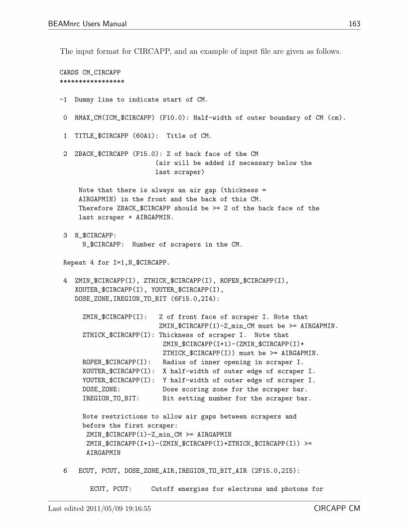
BEAMnrc Users Manual 163
The input format for CIRCAPP, and an example of input file are given as follows.
CARDS CM_CIRCAPP*****************
-1 Dummy line to indicate start of CM.
0 RMAX_CM(ICM_$CIRCAPP) (F10.0): Half-width of outer boundary of CM (cm).
1 TITLE_$CIRCAPP (60A1): Title of CM.
2 ZBACK_$CIRCAPP (F15.0): Z of back face of the CM(air will be added if necessary below thelast scraper)
Note that there is always an air gap (thickness =AIRGAPMIN) in the front and the back of this CM.Therefore ZBACK_$CIRCAPP should be >= Z of the back face of thelast scraper + AIRGAPMIN.
3 N_$CIRCAPP:N_$CIRCAPP: Number of scrapers in the CM.
Repeat 4 for I=1,N_$CIRCAPP.
4 ZMIN_$CIRCAPP(I), ZTHICK_$CIRCAPP(I), ROPEN_$CIRCAPP(I),XOUTER_$CIRCAPP(I), YOUTER_$CIRCAPP(I),DOSE_ZONE,IREGION_TO_BIT (6F15.0,2I4):
ZMIN_$CIRCAPP(I): Z of front face of scraper I. Note thatZMIN_$CIRCAPP(1)-Z_min_CM must be >= AIRGAPMIN.
ZTHICK_$CIRCAPP(I): Thickness of scraper I. Note thatZMIN_$CIRCAPP(I+1)-(ZMIN_$CIRCAPP(I)+ZTHICK_$CIRCAPP(I)) must be >= AIRGAPMIN.
ROPEN_$CIRCAPP(I): Radius of inner opening in scraper I.XOUTER_$CIRCAPP(I): X half-width of outer edge of scraper I.YOUTER_$CIRCAPP(I): Y half-width of outer edge of scraper I.DOSE_ZONE: Dose scoring zone for the scraper bar.IREGION_TO_BIT: Bit setting number for the scraper bar.
Note restrictions to allow air gaps between scrapers andbefore the first scraper:ZMIN_$CIRCAPP(1)-Z_min_CM >= AIRGAPMINZMIN_$CIRCAPP(I+1)-(ZMIN_$CIRCAPP(I)+ZTHICK_$CIRCAPP(I)) >=AIRGAPMIN
6 ECUT, PCUT, DOSE_ZONE_AIR,IREGION_TO_BIT_AIR (2F15.0,2I5):
ECUT, PCUT: Cutoff energies for electrons and photons for
Last edited 2011/05/09 19:16:55 CIRCAPP CM

164 NRCC Report PIRS-0509(A)revL
both the bars and the surrounding (air) regionDOSE_ZONE_AIR: Dose scoring zone for the surrounding region
IREGION_TO_BIT_AIR: Bit set number for the surrounding (air) region
Repeat 7 for I=1,N_$CIRCAPP.
7 MED_IN (24A1): Medium of the bar of scraper I, used toset MED_INDEX.
Example*******
The input defines a circular applicator with 2 scrapers, one of Pb withradius of opening = 0.6cm, X and Y half-widths of 1.0cm, and thickness0.5cm. The other scraper, consisting of Al, has an opening with radius2.4cm, X half-width = 4.6cm, Y half-width = 3.2cm, and thickness 1.0cm.The scrapers are separated by 0.1cm of air. The front scraper starts atZ=1.1cm and the second at 1.6 cm.
Electrons will be followed down to kinetic energies of 10 keV (totalenergies of 0.521 MeV) and photons will be followed down to 1 keV. Thedose deposited in the air will be scored in dose zone 1, and the dose inthe 2 scrapers will be scored in dose zones 2 and 3. There is a minimum0.1 cm air gap at the front and back of the CIRCAPP CM.
14.0, RMAX_CMcircular applicator44.0, extended air to Z=44 cm2, two scrapers1.10, 0.50, 0.600, 1.0, 1.0, 2, 6,1.60, 1.00, 2.40, 4.6, 3.2, 3, 7,0.521, 0.01, 1, 0,PB521ICRUAL521ICRU
15.3.11 PYRAMIDS
The PYRAMIDS CM is used to model pyramid-shaped structures comprising one or morelayers in the path of the beam. Each layer has three distinct regions: the central region(the pyramid), the surrounding region and the outer region (beyond the outer edges of thelayer). The central and outer regions default to air but can also be filled with a user-specifiedmedium (assumed the same for the central and outer regions within a layer). PYRAMIDS isuseful for modelling rectangular collimators and beam blocks. This CM has a square outerboundary centered on the beam axis.
15 COMPONENT MODULES PYRAMIDS CM

BEAMnrc Users Manual 165
PYRAMIDSZ_min_CM (ICM)
Z_min_CM (ICM+1)
ZMAX(1)ZMIN(1)
RMAX_CM(ICM)
Beam Axis
XFP(1)
XBN(1)
XFN(1)
ZMAX(2)ZMIN(2)
MED3
MED6
XBP(1)
MED4=AIR
XMAX(1)
MED6
MED3
MED2 MED2
XMAX(2)
XFN(2) XFP(2)
XBN(2)
MED5
XBP(2)
MED1=AIR
(TOP VIEW)Beam Axis
RMAX_CM
X
Y
MED3
MED6 MED5
Figure 29: A PYRAMIDS component module with 2 layers (ISCM MAX=2). Within a layeri, the front of the central region is specified by XFP(i), XFN(i), YFP(i), YFN(i), and theback is defined by XBP(i), XBN(i), YBP(i), YBN(i). The central region’s inner faces are theplanes connecting rectangle defining the front of the region with that defining the back of theregion. The X and Y outer edges of layer i are defined by XMAX(i) and YMAX(i) respectively.The figure does not show the Y dimensions (i.e. YFN(i), YFP(i), YMAX(i), etc..), howeverthe Y dimensions are evident in the top view. Layers must be separated by at least 0.01cm(ZMIN(i+1)-ZMAX(i) ≥ 0.01cm). By setting IFILL=1, the user can set the medium fillingthe central and outer regions in each layer (MED2 and MED5). The gaps between layers areassumed to be filled with air.
Last edited 2011/05/09 19:16:55 PYRAMIDS CM

166 NRCC Report PIRS-0509(A)revL
The input format for PYRAMIDS and an example input are given below.
CARDS CM_PYRAMIDS(Rev 1.5)*****************
-1 dummy line filled with *** read in main
0 RMAX_CM(ICM_$PYRAMIDS): Perpendicular distance from Z-axisto boundary surrounding componentThis component module has a squareboundary.
1 TITLE_$PYRAMIDS (60A1): Title of CM.
2 ISCM_MAX_$PYRAMIDS, IFILL_$PYRAMIDS (2I5):
ISCM_MAX_$PYRAMIDS: Number of layers in CM.IFILL_$PYRAMIDS: Set to 0 (default) if all central
and outer regions contain air, or 1if central and outer regions containuser-specified media.
Repeat 3 for I=1,ISCM_MAX_$PYRAMIDS
3 ZMIN_$PYRAMIDS(I), ZMAX_$PYRAMIDS(I), XFP_$PYRAMIDS(I),XBP_$PYRAMIDS(I), XFN_$PYRAMIDS(I), XBN_$PYRAMIDS(I),YFP_$PYRAMIDS(I), YBP_$PYRAMIDS(I), YFN_$PYRAMIDS(I),YBN_$PYRAMIDS(I),XMAX_$PYRAMIDS(I), YMAX_$PYRAMIDS(I) (12F15.0):
ZMIN_$PYRAMIDS(I): Distance from front of layer I to reference plane.ZMAX_$PYRAMIDS(I): Distance from back of layer I to reference plane.
XFP_$PYRAMIDS(I): positive x dimension of central region at frontXBP_$PYRAMIDS(I): positive x dimension of central region at backXFN_$PYRAMIDS(I): negative x dimension of central region at frontXBN_$PYRAMIDS(I): negative x dimension of central region at back
YFP_$PYRAMIDS(I): positive y dimension of central region at frontYBP_$PYRAMIDS(I): positive y dimension of central region at backYFN_$PYRAMIDS(I): negative y dimension of central region at frontYBN_$PYRAMIDS(I): negative y dimension of central region at back
XMAX_$PYRAMIDS(I): outer x edge of layer (absolute value)YMAX_$PYRAMIDS(I): outer y edge of layer (absolute value)
Note restriction to leave airgap between layers:ZMIN_$PYRAMIDS(I+1)-ZMAX_$PYRAMIDS(I) >= AIRGAPMIN
4 ECUT, PCUT, DOSE_ZONE, IREGION_TO_BIT (2F15.0,2I5): for AIR
15 COMPONENT MODULES PYRAMIDS CM

BEAMnrc Users Manual 167
between layers, and,if IFILL_$PYRAMIDS=0,in all central and outer regions.
ECUT, PCUT: Cutoff energies for electrons and photons.DOSE_ZONE: Dose scoring zone of air.
IREGION_TO_BIT: mapping of region to bit for LATCH
Repeat 7-8 (IFILL_$PYRAMIDS=0) or 5-8 (IFILL_$PYRAMIDS=1)for I=1,ISCM_MAX_$PYRAMIDS
5 and 6 are required only if IFILL_$PYRAMIDS=1
5 ECUT, PCUT, DOSE_ZONE, IREGION_TO_BIT (2F15.0,2I5):ECUT, PCUT: Cutoff energies for electrons and photons
in central region and outer region, layer IDOSE_ZONE: Dose scoring zone for central region and outer region
IREGION_TO_BIT: mapping of central region and outer region to bitfor LATCH
6 MED_IN (24A1): Medium of central region and outer region in layer I,used to set MED_INDEX.
7 ECUT, PCUT, DOSE_ZONE, IREGION_TO_BIT (2F15.0,2I5):ECUT, PCUT: Cutoff energies for electrons and photons
in surrounding region, layer IDOSE_ZONE: Dose scoring zone of surrounding region.
IREGION_TO_BIT: mapping of surrounding region to bit for LATCH
8 MED_IN (24A1): Medium of surrounding region in layer I,used to set MED_INDEX.
Example*******The following input file describes two pyramidal openings,both 0.3cm thick, and both filled with air (ie IFILL_$PYRAMIDS=0).The first opening begins at Z=0.0 cm and is cut out of Pb. Its positiveX face begins at XFP=0.8cm and angles back to XBP=1.2cm. The negative Xface is a mirror image, beginning at XFN=-0.8cm and going to XBN=-1.2cm.The outer x edge is at XMAX=5.0cm. The Y faces of the first opening areperpendicular to the beam, with YFP=YBP=0.8cm and YFN=YBN=-0.8cm. Theouter y edge is at YMAX=4.6cm.The second opening begins at Z=0.31 and is cut out of aluminum. Itspositive and negative X faces describe a parallelepiped, with XFP=1.2cm,XBP=0.8cm, XFN=-0.8cm, XBN=-1.2cm.The positive Y face angles from YFP=2.0cm toYBP=0.5cm and the negative Y face is a mirror image of this, going fromXFN=-2.0cm to XBN=-0.5cm. The outer x edge and y edge are at XMAX=5.1cm,YMAX=5.2cm respectively. Note that an air gap >= AIRGAPMIN (=0.01cm) mustbe left between pyramids and the top of the CM and the first pyramid.
Last edited 2011/05/09 19:16:55 PYRAMIDS CM

168 NRCC Report PIRS-0509(A)revL
In this particular input file, there is no gap at the top of theCM, so Z_min_CM will be automatically reset to -0.01cm toprovide the required gap.
Dose in the air gaps and openings will be scored in dose zone 1.Dose in the Pb will be scored in zone 2, and dose in the Al will bescored in zone 3. ECUT and PCUT in all regions are set to 0.521MeV and0.01 MeV respectively.
10.0000,PYR2,00.0, 0.3, 0.8, 1.2, -0.8, -1.2, 0.8, 0.8, -0.8, -0.8, 5.0, 4.60.31, 0.61, 1.2, 0.8, -0.8, -1.2, 2.0, 0.5, -2.0, -0.5, 5.1, 5.20.521, 0.01, 1, 00.521, 0.01, 2, 0PB521ICRU0.521, 0.01, 3, 0AL521ICRU
15.3.12 BLOCK
The BLOCK CM is used to model a treatment block having non-rectangular and/or multipleopenings. The user specifies openings in the block material using up to 20 “subregions”. Foreach subregion the user specifies the X-Y coordinates of its vertices at the top surface ofthe block material (either clockwise or counter-clockwise around the perimeter). The innerplanes of all subregions are angled with respect to the beam (Z) axis towards a single user-specified “focus point” on the beam axis. Note that no subregion can have an inner angle> 180 degrees. Openings can consist of a single subregion or may require several adjoiningsubregions in order to avoid the restriction on the inner angles. The user also specifies theX and Y coordinates of the 4 outer edges of the block material, so the material need notextend to the square outer boundary of this CM. Due to its generality, BLOCK may requireup to 2 times the CPU time of PYRAMIDS to simulate simple rectangular geometries; thus,PYRAMIDS is recommended when there is a single rectangular opening.
The current version of BLOCK has been significantly changed from BLOCK in BEAM99(see CHANGES from BEAM99.for.BEAM00). This is because John Antolak of the M.D. Ander-son Cancer Center found and corrected some serious errors in this CM.
15 COMPONENT MODULES BLOCK CM

BEAMnrc Users Manual 169
BLOCK
X−Section through O pening
Top View
RMAX_CM(ICM)
MED3
YPMAXYNMAX
XPMAX
XNMAX
XHI_POINT (1,1)YHI_POINT (1,1)
XHI_POINT (2,1)YHI_POINT (2,1)
XHI_POINT (3,1)YHI_POINT (3,1)
XHI_POINT (4,1)YHI_POINT (4,1)
XHI_POINT (5,1)YHI_POINT (5,1)
X
Y
Y
RMAX_CM(ICM)
ZFOCUS
beam axis (Z)
MED3
ZMIN
Z_min_CM (ICM)
Z_min_CM (ICM+1)
ZMAX
MED1=AIR
YPMAXYNMAX
MED2
MED2
MED2 MED2
Figure 30: A BLOCK component module with a single opening composed of 1 sub-region (ISUB MAX=1). As shown in the top view, the subregion has 5 vertices(NSUB(1)=5). The X-Y coordinates of the vertices at the top surface of the block mate-rial are specified counter-clockwise around the perimeter of the subregion, beginning with(XHI POINT(1,1),YHI POINT(1,1)). Also shown in the top view are the coordinates definingthe outer boundary of the block, XPMAX, YPMAX, XNMAX and YNMAX. The cross-section throughthe opening shows that the planes defining the inner surfaces of the subregion/opening areall angled with respect to the Z-axis towards the single focus point on the Z-axis. Note thatthere must be an air gap between ZMIN and Z min CM(ICM) of ≥ 0.01 cm. Note that the userspecifies MED2, the material filling the opening(s) and the region beyond the block edges.The top gap is assumed to be air. More complicated opening shapes may require severaladjoining subregions.
Last edited 2011/05/09 19:16:55 BLOCK CM

170 NRCC Report PIRS-0509(A)revL
The input format for BLOCK and an example input are given below.
CARDS CM_BLOCK(Rev 1.4)*****************
-1 dummy line filled with *** read in main
0 RMAX_CM(ICM_$BLOCK): Perpendicular distance from Z-axisto boundary surrounding componentThis component module has a squareboundary.
1 TITLE_$BLOCK (60A1): Title of CM.
2 ZMIN_$BLOCK, ZMAX_$BLOCK, ZFOCUS_$BLOCK (3F15.0):
ZMIN_$BLOCK: Z of front of CM (not including airgap) (cm).ZMAX_$BLOCK: Z of back of CM (cm).
ZFOCUS_$BLOCK: Z at which the inner sides of the opening(s)in the block are focused (cm).
Note restrictions: ZMAX < ZFOCUS or ZFOCUS < ZMIN, ie not in betweenZMIN - ZFOCUS >= 0.01 if ZFOCUS < ZMIN
3 ISUB_MAX_$BLOCK (I5): Number of subregions. Each opening is madeup of one or more subregions.
Repeat 4 - 4a for J = 1, ISUB_MAX_$BLOCK
4 NSUB_$BLOCK(J) (I5)
NSUB_$BLOCK(J): number of points defining subregion J
Repeat 4a for I = 1, NSUB_$BLOCK(J)
4a XHI_POINT_$BLOCK(I,J),YHI_POINT_$BLOCK(I,J) (2F15.0):
XHI_POINT_$BLOCK(I,J): X coordinate of point I at upper surface (cm)YHI_POINT_$BLOCK(I,J): Y coordinate of point I at upper surface (cm)
NOTE: Input the points clockwise or counter-clockwise aroundthe perimeter of each subregion. A subregion may nothave an interior angle > 180 degrees.
5 XPMAX_$BLOCK,YPMAX_$BLOCK,XNMAX_$BLOCK,YNMAX_$BLOCK (4F15.0):
XPMAX_$BLOCK: X coordinate of block edge in +X direction (cm)YPMAX_$BLOCK: Y coordinate of block edge in +Y direction (cm)XNMAX_$BLOCK: X coordinate of block edge in -X direction (cm)
15 COMPONENT MODULES BLOCK CM

BEAMnrc Users Manual 171
YNMAX_$BLOCK: Y coordinate of block edge in -Y direction (cm)
6 ECUT, PCUT, DOSE_ZONE, IREGION_TO_BIT (2F15.0,2I5) for airin gap at top.
ECUT, PCUT: Cutoff energies for electrons and photons.DOSE_ZONE: Dose scoring zone of air.
IREGION_TO_BIT: mapping of region to bit for LATCH
7 ECUT, PCUT, DOSE_ZONE, IREGION_TO_BIT (2F15.0,2I5) in openingsand beyond edges of the block
ECUT, PCUT: Cutoff energies for electrons and photons inopenings and beyond edges of block
DOSE_ZONE: Dose scoring zone of openings and region beyondedges of block
IREGION_TO_BIT: mapping of region comprising openings and regionbeyond block edges to bit for LATCH
8 MED_IN (24A1): Medium in openings and beyond block edges,used to set MED_INDEX.
9 ECUT, PCUT, DOSE_ZONE, IREGION_TO_BIT (2F15.0,2I5) in block material
ECUT, PCUT: Cutoff energies for electrons and photonsin material surrounding openings
DOSE_ZONE: Dose scoring zone of material surroundingopenings.
IREGION_TO_BIT: mapping of region surrounding openingsto bit for LATCH
10 MED_IN (24A1): Medium of block,used to set MED_INDEX.
Example*******The following input file describes a BLOCK of 4cm thick.The block begins at Z=0.0 cm and is made of MILDSTEEL. The air-filledopening(s) focus at Z=-10cm. Its positive X boundary begins at XPMAX=4.2cm,positive Y boundary at YPMAX=4.8cm, and its negative X boundary atXNMAX=-5.0cm, negative Y boundary at YNMAX=-3.0cm.There are 2 sub-regions describing one opening shaped like an arrow.In the first sub-region, there are 5 defining points; in the second one,there are 4 defining points. The defining points should be inputclockwisely or counter-clockwisely. Each point is input as x, y ina line.In this particular input file, there is no gap at the top of theCM, so Z_min_CM will be automatically reset to -0.01cm toprovide the required gap.
Last edited 2011/05/09 19:16:55 BLOCK CM

172 NRCC Report PIRS-0509(A)revL
Dose in the air regions will be scored in dose zone 1.Dose in the block material will be scored in zone 2.ECUT and PCUT in all regions are set to 0.521MeV and0.01 MeV respectively.
***********************************************10.0, RMAXarrow shaped cutoff0.0, 4.0, -10.0, ZMIN, ZMAX, ZFOCUS2, 2 sub-regions5, 5 defining points in sub 10., 3., x,y of point 1 in sub 1-2., 1., x,y of point 2 in sub 1-1., 0., x,y of point 3 in sub 11., 0., x,y of point 4 in sub 12., 1., x,y of point 5 in sub 1 end of sub 14, 4 defining points in sub 2-1., 0., x,y of point 1 in sub 21., 0., x,y of point 2 in sub 21., -2., x,y of point 3 in sub 2-1., -2., x,y of point 4 in sub 2. end of sub 2.4.2, 4.8, -5.0, -3.0, xpmax,ypmax,xnmax,ynmax0.0, 0.0, 1, 0, ecut, pcut, dose-zone, ir-to-bit for air0.0, 0.0, 1, 0, ecut, pcut, dose-zone, ir-to-bit for openingsAIR521ICRU0.0, 0.0, 2, 0, ecut, pcut, dose-zone, ir-to-bit for materailMILDSTEEL521***********************************************
15.3.13 MLC
The MLC CM is used to model a double-focusing multi-leaf collimator with flat faces. Thecollimator has a single layer with a user-specified number of leaves all opening in either the Xor Y direction. The collimator opening is specified by the coordinates of the individual leafopenings at the top of the collimator, the thickness of the leaves in the Z direction, and twoZ ”foci” that determine the angles of the leaf side and end surfaces. The outer boundary ofthe MLC CM is a square centred on the beam axis. Currently, the collimator body extendsto this outer boundary.
15 COMPONENT MODULES MLC CM

BEAMnrc Users Manual 173
MLC
X
Y
RMAX_CM(ICM)
MED1
MED2
TWIDTH
leaf 1 2 3 4 5 6
POS
NEG
RMAX_CM(ICM)
ZFOCUS(1)
Y
beam axis (Z)
MED1 MED2 ZTHICK
leaf sides
leaf 1 2 3 4 5 6
TWIDTH
ZMIN
beam axis (Z)
X
ZFOCUS(2)
RMAX_CM(ICM)
AIR
MED1 MED2
NEG POS
leaf ends
Z_min_CM (ICM)
Z_min_CM (ICM+1)
X−Section Perpendic ular to Leav es
X−Section Parallel to Leaves
Top View
Figure 31: An MLC component module with 6 leaves (NUM LEAF=6) opening in the X direc-tion (IDMLFC=1). The cross-section perpendicular to the leaves (in the Y direction) showsthe total width of the leaves at the top of the collimator, TWIDTH. The width of each leaf atthe top is TWIDTH/NUM LEAF. Note that NUM LEAF must be an even number so that there isan equal number of leaves on either side of the X axis. The Y coordinates of the leaves atthe bottom of the collimator are calculated automatically so that the tangents to the sidesurfaces of the leaves all cross the Z-axis at Z=ZFOCUS(1). The cross-section parallel to theleaves (in the X direction) shows the negative, NEG, and positive, POS, coordinates of theopening in one leaf. NEG and POS coordinates are input for every leaf. The X coordinatesof the leaf openings at the bottom of the collimator are calculated automatically so thatthe tangents to the leaf ends all cross the Z-axis at Z=ZFOCUS(2). The top view of thecollimator shows how the collimator opening is composed of the individual leaf openings.MED1 defines the material in the collimator opening and MED2 defines the material of thecollimator leaves and body. This example would be applicable to leaves opening in the Ydirection (IDMLFC=0) by reversing the roles of X and Y. Although this particular exampleshows ZFOCUS points that are < ZMIN, the ZFOCUS points can also be > ZMIN+ZTHICK, inwhich case leaf surfaces angle in towards the Z-axis with increasing Z.
Last edited 2011/05/09 19:16:55 MLC CM

174 NRCC Report PIRS-0509(A)revL
The input format for MLC and an example input are given below.
CARDS CM_$MLC**************-1 Dummy line to indicate start of CM
0 RMAX_CM(ICM_$MLC) (F10.0): Half-width of CM boundary (cm).
1 TITLE_$MLC (60A1): Title of CM.
2 IDMLFC_$MLC (I5) = 0 for leaves parallel to Y direction= 1 for leaves parallel to X direction
3 ZMIN_$MLC (F15.0): Z of top of collimator (excluding airgap)
4 ZTHICK_$MLC (F15.0): Thickness of the leaves (cm)
5 NUM_LEAF_$MLC, TWIDTH_$MLC (I5,F15.0)
NUM_LEAF_$MLC: Number of leavesTWIDTH_$MLC: Total width of leaves in X (IDMLFC_$MLC=0)
or Y (IDMLFC_$MLC=1) direction (cm)
Note: width of each leaf = TWIDTH_$MLC/NUM_LEAF_$MLC
6 ZFOCUS_$MLC(1) (F15.0): Focal point on Z-axis of leaf sides (ie.imaginary lines drawn extending the slopes ofthe leaf sides will all intersect the Z-axisat this point)
Note restriction: ZFOCUS_$MLC(1) < ZMIN_$MLC or> ZMIN_$MLC + ZTHICK_$MLC
7 ZFOCUS_$MLC(2) (F15.0): Focal point on Z-axis of leaf ends (ie.imaginary lines drawn extending the slopes ofthe leaf ends will all intersect the Z-axisat this point)
Note restriction: ZFOCUS_$MLC(1) < ZMIN_$MLC or> ZMIN_$MLC + ZTHICK_$MLC
Repeat 8 until coordinates of all leaves are defined once. Leavesare numbered 1,2,...NUM_LEAF_$MLC, where numbering goes from leftto right in the X-Y plane if IDMLFC_$MLC=0 and from top to bottomin the X-Y plane if IDMLFC_$MLC=1.
8 NEG_$MLC, POS_$MLC, NUM_$MLC (2F15.0,I5)
NEG_$MLC: Min. Y (IDMLFC_$MLC=0) or X (IDMLFC_$MLC=1)
15 COMPONENT MODULES MLC CM

BEAMnrc Users Manual 175
of front opening in leaf I (ie the opening atZMIN_$MLC)
POS_$MLC: Max. Y (IDMLFC_$MLC=0) or X (IDMLFC_$MLC=1)of front opening in leaf I
NUM_$MLC: Apply NEG_$MLC(I) and POS_$MLC(I) to leavesI,...,I+NUM_$MLC-1. Defaults to 1 if set <= 0.Defaults to NUM_LEAF_$MLC-I+1 if set >NUM_LEAF_$MLC-I+1
9 ECUT, PCUT, DOSE_ZONE, IREGION_TO_BIT in local region 1(inside collimator) (2F15.0,I5):
ECUT, PCUT: Cutoff energies for electrons and photons.DOSE_ZONE: Dose scoring flag, 0 to not score dose
IREGION_TO_BIT: Bit number associated with this region
10 MED_IN (24A1): Medium of in local region 1 (inside collimator)used to set MED_INDEX.
11 ECUT, PCUT, DOSE_ZONE, IREGION_TO_BIT in local region 2(collimator leaves) (2F15.0,I5):
ECUT, PCUT: Cutoff energies for electrons and photons.DOSE_ZONE: Dose scoring flag, 0 to note score dose
IREGION_TO_BIT: Bit number associated with this region
12 MED_IN (24A1): Medium of local region 2 (collimator leaves),used to set MED_INDEX.
Example*******
The following example defines a multi-leaf collimator design basedloosely on that used with the MM50 Racetrack Microtron accelerator.The collimator starts at Z=65 cm and has 64 tungsten leaves openingin the X direction. The leaves are each 0.8125cm wide and 7.5cmthick. The Z focus of the leaf sides is at Z=-1000 cm, resultingin sides that are essentially straight up and down. The Z focusof the leaf ends is at Z=0, which is the position of the beam source.In this example, leaf opening coordinates are chosen to create airregular off-center collimator opening.
Electrons and photons in both the collimator and the opening regionswill be followed down to kinetic energies of 10 keV (ECUT=0.521,PCUT=0.01). Dose deposited in the tungsten leaves will be storedin dose zone 2, and dose deposited in the opening will be storedin dose zone 1.
26.0, RMAX_CM
Last edited 2011/05/09 19:16:55 MLC CM

176 NRCC Report PIRS-0509(A)revL
Collimator based on MLC for MM50 accelerator1, Leaves open in X direction65.0, ZMIN7.5, ZTHICK64, 52.0, NUM_LEAF, TWIDTH-1000.0, ZFOCUS(1)0.0 ZFOCUS(2)0.0,0.0,15, 15 closed leaves0.0,2.0,5, 5 leaves with opening 0.0 - 2.00.5,3.0,2 2 leaves with 0.5 - 3.01.0,4.0,3 3 leaves with 1.0 - 4.02.0,7.0,10, 10 leaves with opening 2.0 - 7.01.5,6.01.0,6.00.0,5.0,3, 3 leaves with 0.0 - 5.0-1.0,4.0,5, 5 leaves with -1.0 - 4.0-2.0,4.0,3, 3 leaves with -2.0 - 4.0-4.0,4.0,5, 5 leaves with -4.0 - 4.0-5.0,3.0-6.0,1.0-8.0,0.0-10.0,-2.0,3, 3 leaves with -10.0 - -2.0-12.0,-2.0,2, 2 leaves with -12.0 - -2.0-15.0,-3.0,2, 2 leaves with -15.0 - -3.0-15.0,-15.00.5210, 0.010, 1, 0AIR700ICRU0.5210, 0.010, 2, 0W700ICRU
15.3.14 MLCQ
The MLCQ CM is used to model a focusing multi-leaf collimator with rounded leaf ends.The collimator is similar to MLC with the exception that, rather than specifying a Z focusfor the leaf ends, the user specifies a radius for the leaf ends and the Z position of the originof this radius (i.e. so the leaf ends can be angled up or down). The collimator opening isdefined by specifying the X or Y (depending on leaf orientation) origin of the radius for thepositive and negative portions of each leaf.
The first version of this CM, which was based on MLC, was coded by Hugo Palmans andKristiaan De Vlamynck of the University of Gent, Belgium.
15 COMPONENT MODULES MLCQ CM

BEAMnrc Users Manual 177
MLCQ
X
Y
RMAX_CM(ICM)
MED1
MED2
TWIDTH
leaf 1 2 3 4 5 6
X0P
X0N
RMAX_CM(ICM)
ZFOCUS(1)
Y
beam axis (Z)
MED1 MED2 ZTHICK
leaf sides
leaf 1 2 3 4 5 6
TWIDTH
ZMIN
beam axis (Z)
X
RMAX_CM(ICM)
leaf ends
X−Section Perpendic ular to Leav es
X−Section Parallel to Leaves
Top View
X0N X0P
Z_min_CM (ICM+1)
Z0LEAF
MED2R0LEAF
AIRZ_min_CM (ICM)
MED1
Figure 32: An MLCQ component module with 6 leaves (NUM LEAF=6) opening in the Xdirection (IDMLFC=1). Parameters are similar to MLC with the exception of those for theleaf ends. The cross-section parallel to the leaves shows how the rounded leaf ends aredefined. Basically, for each leaf, the user defines a circle with radius R0LEAF (the radius ofthe leaf ends), centred at (X0N,Z0LEAF) for the negative portion of the leaf and (X0P,Z0LEAF)for the positive portion of the leaf. Note that X0N,X0P define X coordinates if the leaves areparallel to the X direction and Y coordinates if the leaves are parallel to the Y direction. Alsonote that Z0LEAF applies to all leaves. The rounded leaf end is then the arc subtended bythe intersection of this circle with ZMIN and ZMIN + ZTHICK. The user controls the angle ofthe leaf ends with respect to the Z axis using Z0LEAF and the dimensions of the leaf openingusing X0N and X0P. The top view shows that ABS(X0N) and ABS(X0P) can be > RMAX CM,however the points of intersection of the circle defining a leaf end with ZMIN and ZMIN +
ZTHICK must be within the boundaries of the CM or else the volume/mass of the collimatorwill be determined incorrectly for dose calculations.
Last edited 2011/05/09 19:16:55 MLCQ CM

178 NRCC Report PIRS-0509(A)revL
The input format for MLCQ and an example input are given below.
CARDS CM_$MLCQ**************-1 Dummy line to indicate start of CM
0 RMAX_CM(ICM_$MLCQ) (F10.0): Half-width of CM boundary (cm).
1 TITLE_$MLCQ (60A1): Title of CM.
2 IDMLFC_$MLCQ (I5) = 0 for leaves parallel to Y direction= 1 for leaves parallel to X direction
3 ZMIN_$MLCQ (F15.0): Z of top of collimator (excluding airgap)
4 ZTHICK_$MLCQ (F15.0): Thickness of the leaves (cm)
5 NUM_LEAF_$MLCQ, TWIDTH_$MLCQ (I5,F15.0)
NUM_LEAF_$MLCQ: Number of leavesTWIDTH_$MLCQ: Total width of leaves in X (IDMLFC_$MLCQ=0)
or Y (IDMLFC_$MLCQ=1) direction (cm)
Note: width of each leaf = TWIDTH_$MLCQ/NUM_LEAF_$MLCQ
6 ZFOCUS_$MLCQ(1) (F15.0): Focal point on Z-axis of leaf sides (ie.imaginary lines drawn extending the slopes ofthe leaf sides will all intersect the Z-axisat this point)
Note restriction: ZFOCUS_$MLCQ(1) < ZMIN_$MLCQ or> ZMIN_$MLCQ + ZTHICK_$MLCQ
7 R0LEAF_$MLCQ,Z0LEAF_$MLCQ (2F15.0)
R0LEAF_$MLCQ: Radius of leaf ends in cm.Z0LEAF_$MLCQ: Z where radius of leaf ends originates in cm.
Note restrictions: 1. ZMIN_$MLCQ < Z0LEAF_$MLCQ <ZMIN_$MLCQ + ZTHICK_$MLCQ
2. R0LEAF_$MLCQ >MAX(ZMIN_$MLCQ+ZTHICK_$MLCQ-Z0LEAF_$MLCQ,
Z0LEAF_$MLCQ-ZMIN_$MLCQ)Repeat 8 until coordinates of all leaves are defined once. Leavesare numbered 1,2,...NUM_LEAF_$MLCQ, where numbering goes from leftto right in the X-Y plane if IDMLFC_$MLCQ=0 and from top to bottomin the X-Y plane if IDMLFC_$MLCQ=1.
8 X0N_$MLCQ, X0P_$MLCQ, NUM_$MLCQ (2F15.0,I5)
15 COMPONENT MODULES MLCQ CM

BEAMnrc Users Manual 179
X0N_$MLCQ: Y (IDMLFC_$MLCQ=0) or X (IDMLFC_$MLCQ=1)of origin of radius of negative part of leaf I
XOP_$MLCQ: Y (IDMLFC_$MLCQ=0) or X (IDMLFC_$MLCQ=1)of origin of radius of positive part of leaf I
NUM_$MLCQ: Apply X0N_$MLCQ and X0P_$MLCQ to leavesI,...,I+NUM_$MLCQ-1. Defaults to 1 if set <= 0.Defaults to NUM_LEAF_$MLCQ-I+1 if set >NUM_LEAF_$MLCQ-I+1
9 ECUT, PCUT, DOSE_ZONE, IREGION_TO_BIT in local region 1(inside collimator) (2F15.0,I5):
ECUT, PCUT: Cutoff energies for electrons and photons.DOSE_ZONE: Dose scoring flag, 0 to not score dose
IREGION_TO_BIT: Bit number associated with this region
10 MED_IN (24A1): Medium of in local region 1 (inside collimator)used to set MED_INDEX.
11 ECUT, PCUT, DOSE_ZONE, IREGION_TO_BIT in local region 2(collimator leaves) (2F15.0,I5):
ECUT, PCUT: Cutoff energies for electrons and photons.DOSE_ZONE: Dose scoring flag, 0 to note score dose
IREGION_TO_BIT: Bit number associated with this region
12 MED_IN (24A1): Medium of local region 2 (collimator leaves),used to set MED_INDEX.
Example*******
The following example defines a multi-leaf collimatorthat starts at Z=65 cm and has 64 tungsten leaves openingin the X direction. The leaves are each 0.8125cm wide and 7.5cmthick. The Z focus of the leaf sides is at Z=-1000 cm, resultingin sides that are essentially straight up and down. The radiusof the leaf ends is 10cm and has a Z origin of 65cm (ie ZMIN),The unique position of the Z origin of the radius means that the Xdimensions of the opening in each leaf at the top of the collimator(ZMIN) will be given by X0N+10 - X0P-10 cm.In this example, the X origins of the radii of the individual leavesare chosen to create an irregular off-center collimator opening.
Electrons and photons in both the collimator and the opening regionswill be followed down to kinetic energies of 10 keV (ECUT=0.521,PCUT=0.01). Dose deposited in the tungsten leaves will be storedin dose zone 2, and dose deposited in the opening will be stored
Last edited 2011/05/09 19:16:55 MLCQ CM

180 NRCC Report PIRS-0509(A)revL
in dose zone 1.
26.0, RMAX_CMCollimator based on MLC for MM50 accelerator1, Leaves open in X direction65.0, ZMIN7.5, ZTHICK64, 52.0, NUM_LEAF, TWIDTH-1000.0, ZFOCUS(1)10.0,65.0 R0LEAF,Z0LEAF-10.0,10.0,15, 15 leaves closed at top-10.0,12.0,5, 5 leaves with opening 0.0 - 2.0 at top-9.5,13.0,2 2 leaves with 0.5 - 3.0 at top-9.0,14.0,3 3 leaves with 1.0 - 4.0 at top-8.0,17.0,10, 10 leaves with opening 2.0 - 7.0 at top-8.5,16.0-9.0,16.0-10.0,15.0,3, 3 leaves with 0.0 - 5.0 at top-11.0,14.0,5, 5 leaves with -1.0 - 4.0 at top-12.0,14.0,3, 3 leaves with -2.0 - 4.0 at top-14.0,14.0,5, 5 leaves with -4.0 - 4.0 at top-15.0,13.0-16.0,11.0-18.0,10.0-20.0,8.0,3, 3 leaves with -10.0 - -2.0 at top-22.0,8.0,2, 2 leaves with -12.0 - -2.0 at top-25.0,7.0,2, 2 leaves with -15.0 - -3.0 at top-25.0,-5.00.5210, 0.010, 1, 0AIR700ICRU0.5210, 0.010, 2, 0W700ICRU
15.3.15 VARMLC
The VARMLC CM is used to model a focusing multi-leaf collimator with either roundedleaf ends or straight leaf ends with a Z focus. The major difference between VARMLC andMLC or MLCQ is that VARMLC simulates the air gaps between leaves, the tongue-in-groovemechanism by which adjacent leaves slide against each other, and the driving screws at thetop and bottom of each leaf used to open and close the leaves. VARMLC can also simulateleaves of different widths within the same collimator. In VARMLC the medium beyond theleaves in the direction perpendicular to the leaves defaults to be the same as the medium inthe leaf opening(s) (ie AIR). This is different from MLC and MLCQ in which the mediumin this region defaults to the leaf medium (ie solid). This default can be changed within theVARMLC cm.mortran and VARMLC macros.mortran codes.
The first version of this CM was coded by Ajay Kapur with Charlie Ma at StanfordUniversity. The current version has significant modifications.
15 COMPONENT MODULES VARMLC CM

BEAMnrc Users Manual 181
ZZRMAX_CM
ZTHICK/2NEG POS
ZFOCUS(2)
NEG POS
ENDTYPE=0 ENDTYPE=1LEAFRADIUS Y
Y
Y cross-section
VARMLC
XZFOCUS(1)
leaf 1 2Z RMAX_CM
3 4
ZTHICK
ZMIN
MED2
MED1
X cross-section
WTONGUE
Z_min_CM
HSCREWHTONGUE
ZMIN
HSCREW
START RMAX_CM
X
Y
Top ViewZTONGUE ZGROOVE
HGROOVE
START WSCREW
LEAFWIDTH(4)
WGROOVE
LEAFGAPWSCREW
LEAFWIDTH(1) LEAFWIDTH(4)
LEAFGAPLEAFWIDTH(1)
Figure 33: A VARMLC component module with 4 leaves (NUM LEAF=4) opening in the Ydirection (ORIENT=0). The X cross-section (perpendicular to the leaf direction) shows thewidths of the leaves (LEAFWIDTH(1)...LEAFWIDTH(4)) and the dimensions of the leaf gap(LEAFGAP), tongue-in-groove mechanism (WGROOVE, HGROOVE, WTONGUE, HTONGUE) and thedriving screws (WSCREW, HSCREW) as input by the user. The user also sets the position ofthe top of the tongue, ZTONGUE, and the top of the groove, ZGROOVE, with the restrictionthat the tongue and groove cannot overlap. If ZTONGUE=ZGROOVE=0 then the tongue andgroove are centred at Z = ZMIN + ZTHICK/2. For restrictions on leaf gap and tongue-in-groove inputs, see the detailed description of input parameters below. Note that all leafside surfaces are focused at ZFOCUS(1) and that horizontal dimensions (WGROOVE, WTONGUE,
WSCREW, START) are all given at ZMIN. Due to LEAFGAP and varying LEAFWIDTH the leavesmay not be symmetric about the Z axis, although START can be set to give approximatesymmetry. Also note that the medium in regions beyond the leaves perpendicular to theleaf direction defaults to MED1, the medium of the openings and air gaps. Y cross-sectionsare shown for leaves with rounded ends (ENDTYPE=0) and straight ends (ENDTYPE=1). Forrounded ends, the user inputs the radius of the ends (LEAFRADIUS) and, for each leaf, theminimum and maximum coordinates of the leaf opening at Z = ZMIN + ZTHICK/2 (NEG,POS). The end radius is always assumed to originate at Z = ZMIN + ZTHICK/2. For straightleaf ends, the user inputs the Z focus of the ends (ZFOCUS(2)) and, for each leaf, the minimumand maximum coordinates of the opening at Z = ZMIN (NEG, POS).
Last edited 2011/05/09 19:16:55 VARMLC CM

182 NRCC Report PIRS-0509(A)revL
The input format for VARMLC and an example input are given below.
CARDS CM_$VARMLC**************-1 Dummy line to indicate start of CM
0 RMAX_CM(ICM_$VARMLC) (F10.0): Half-width of CM boundary (cm).
1 TITLE_$VARMLC (60A1): Title of CM.
2 ORIENT_$VARMLC, NGROUP_$VARMLC (2I5)
ORIENT_$VARMLC= 0 for leaves parallel to Y direction= 1 for leaves parallel to X direction
NGROUP_$VARMLC= number of groups of adjacent leaves whereall leaves in a group have the same width(defaults to 1 if set <= 0)
3 ZMIN_$VARMLC (F15.0): Z of top of MLC (excluding airgap)
4 ZTHICK_$VARMLC (F15.0): Thickness of the leaves ( z-axis (cm))
Repeat 5 NGROUP_$VARMLC times
5 NUM_LEAF_$VARMLC(I), LEAFWIDTH_$VARMLC(I) (I5,F15.0)
NUM_LEAF_$VARMLC(I): Number of adjacent leaves in group ILEAFWIDTH_$VARMLC(I): Width of each leaf in group I
as projected at ZMIN_$VARMLC - the width doesnot include the tongue (see figure).
Note: total number of leaves is stored in TOT_LEAF_$VARMLC
6 START_$VARMLC (F15.0) : the start position (cm) wrt the CAX ofleaf 1 tongue as projected to ZMIN_$VARMLC.
7 WSCREW_$VARMLC, HSCREW_$VARMLC (2F15.0) : The width and heightof the screw on the carriage railing. The width isas projected at ZMIN_$VARMLC and the height projected atthe z-axis.
8 WTONGUE_$VARMLC, HTONGUE_$VARMLC, ZTONGUE_$VARMLC (3F15.0) :The width and height of the tongue projected to ZMIN_$VARMLCand z-axis respectively and the Z starting position of thetongue. ZTONGUE_$VARMLC=0 assumes that the tongue is centredat ZMIN_$VARMLC+ZTHICK_$VARMLC/2 (ie centre of leaf body).
9 WGROOVE_$VARMLC, HGROOVE_$VARMLC, ZGROOVE_$VARMLC (3F15.0) : Thewidth and height of the groove projected to ZMIN_$VARMLC
15 COMPONENT MODULES VARMLC CM

BEAMnrc Users Manual 183
and z-axis respectively and the Z starting position of thegroove. ZGROOVE_$VARMLC=0 assumes that the groove is centredat ZMIN_$VARMLC+ZTHICK_$VARMLC/2 (ie centre of leaf body).
Note restriction: ZTONGUE >= ZGROOVEZTONGUE+HTONGUE <= ZGROOVE+HGROOVEWTONGUE <= WGROOVE
10 LEAFGAP_$VARMLC (F15.0) : The width of the interleaf air gapat ZMIN_$VARMLC.
Note restriction: LEAFGAP_$VARMLC <=WTONGUE_$VARMLC
11 ENDTYPE_$VARMLC (I5) : The type of leaf end :0 -- rounded leaf end and1 -- focused divergent leaf end.
12 ZFOCUS_$VARMLC (F15.0) : Focal point on Z-axis of leaf ends(i.e. imaginary lines drawn extending the slopesof leaf ends will all intersect the Z-axisat this point) - chosen if ENDTYPE_$VARMLC = 1.
Note restriction: ZFOCUS_$VARMLC(1) < ZMIN_$VARMLC or> ZMIN_$VARMLC + ZTHICK_$VARMLC
LEAFRADIUS_$VARMLC (F15.0) : Radius of the leaf end ifENDTYPE_$VARMLC = 0. This must be greaterthan or equal to half the leaf thickness.
13 ZFOCUS_$VARMLC(1) (F15.0): Focal point on Z-axis of leaf sidesimaginary lines drawn extending the slopes ofthe leaf sides will all intersect the Z-axisat this point)
Note restriction: ZFOCUS_$VARMLC(1) < ZMIN_$VARMLC or> ZMIN_$VARMLC + ZTHICK_$VARMLC
For focused ends the leaf position is definedat ZMIN_$VARMLC; for rounded at ZMIN_$VARMLC +
0.5*ZTHICK_$VARMLC (ie center of the leaf in z)
Repeat 14 until coordinates of all leaves are defined once. Leavesare numbered 1,2,...TOT_LEAF_$VARMLC, where numbering goes from leaf1 to leaf TOT_LEAF_$VARMLC. Convention is lower to upper orleft to right depending on ORIENT_$VARMLC i.e from negative topositive.
14 NEG_$VARMLC, POS_$VARMLC, NUM_$VARMLC (2F15.0,I5)
Last edited 2011/05/09 19:16:55 VARMLC CM

184 NRCC Report PIRS-0509(A)revL
NEG_$VARMLC: Min. Y (ORIENT_$VARMLC=0) or X (ORIENT_$VARMLC=1)of front opening in leaf I (ie the opening atZMIN_$VARMLC) if ENDTYPE=1, or of rounded endof leaf I if ENDTYPE=0.
POS_$VARMLC: Max. Y (ORIENT_$VARMLC=0) or X (ORIENT_$VARMLC=1)of front opening in leaf I if ENDTYPE=1, or ofrounded end of leaf I if ENDTYPE=0.
NUM_$VARMLC: Apply NEG_$VARMLC and POS_$VARMLC to leavesI,...,I+NUM_$VARMLC-1. Defaults to 1 if set <=0.Defaults to TOT_LEAF_$VARMLC-I+1 if set >TOT_LEAF_$VARMLC-I+1.
15 ECUT, PCUT, DOSE_ZONE, IREGION_TO_BIT in opening(s) andair gaps (2F15.0,2I5)
ECUT, PCUT: Cutoff energies for electrons and photons.DOSE_ZONE: Dose scoring flag, 0 to not score dose
IREGION_TO_BIT: Bit number associated with this region
16 MED_IN (24A1): Medium in opening(s) and air gapsused to set MED_INDEX.
17 ECUT, PCUT, DOSE_ZONE, IREGION_TO_BIT in leaves, IGNOREGAPS_$VARMLC(2F15.0,3I5):
ECUT, PCUT: Cutoff energies for electrons and photons.DOSE_ZONE: Dose scoring flag, 0 to note score dose
IREGION_TO_BIT: Bit number associated with this regionIGNOREGAPS: If set to 1, ignore all air gaps when doing range
rejection in leaf material when the particle Xpositionis < min X of all leaf openings (not including leafends) or > max X of leaf openings (not including ends)(ORIENT_$VARMLC=1) or if the particle Y positionis < min Y of all leaf openings (not including leafends) or > max Y of leaf openings (not including ends)(ORIENT_$VARMLC=0). This approximation is designedto make range rejection more efficient deep in theleaves, while still preserving accurate transportin the leaf ends. Note that if you have significantair gaps between leaves, it is recommended thatyou not use this option (ie run with the defaultsetting of 0).
18 MED_IN (24A1): Medium of leaves,used to set MED_INDEX.
Example*******
15 COMPONENT MODULES VARMLC CM

BEAMnrc Users Manual 185
The following example defines a multi-leaf collimator design basedloosely on that used with the Varian Clinac 2100C 26 leaf pair.Actual parameters are DIFFERENT - this serves just as a template.Do not attempt to use these parameters for a simulation of the realmachine.
The collimator starts at Z=50 cm and has 26 tungsten leaves openingin the X direction. The leaves are each 0.5cm wide and 6.0cmthick. The Z focus of the leaf sides is at Z=-1000 cm, resultingin sides that are essentially straight up and down. The Z focusof the leaf ends is at Z=0, which is the position of the beam source.In this example, leaf opening coordinates are chosen to create apattern of alternating open and closed leaves.
Electrons and photons in both the collimator and the opening regionswill be followed down to kinetic energies of 10 keV (ECUT=0.521,PCUT=0.01). Dose deposited in the tungsten leaves will be storedin dose zone 2, and dose deposited in the opening will be storedin dose zone 1. Finally, the option to ignore air gaps when doingrange rejection deep in the leaves is off.
26.0, RMAX_CMMLC based on mock 26 leaf pair Varian 2100C type of accelerator1,1, Leaves open in X direction, all have same thickness50.0, ZMIN6.0, ZTHICK26, 0.50, NUM_LEAF, LEAFWIDTH-6.5, START POSITION0,2, 0,4, WIDTH AND HEIGHT OF SCREW0.2, 2,0, WIDTH, HEIGHT, Z OF TONGUE, tongue centred in leaf0.21,2.6,0, WIDTH, HEIGHT, Z OF GROOVE, groove centred in leaf0.005, LEAFGAP BETWEEN ADJACENT LEAVES1, ENDTYPE IS FOCUSED AND DIVERGENT0.0, ZFOCUS(2)-1000.0 ZFOCUS(1)0.0,0.0-5.0, 5.00.0,0.0-5.0, 5.00.0,0.0-5.0, 5.00.0,0.0-5.0, 5.00.0,0.0-5.0, 5.00.0,0.0-5.0, 5.00.0,0.0
Last edited 2011/05/09 19:16:55 VARMLC CM
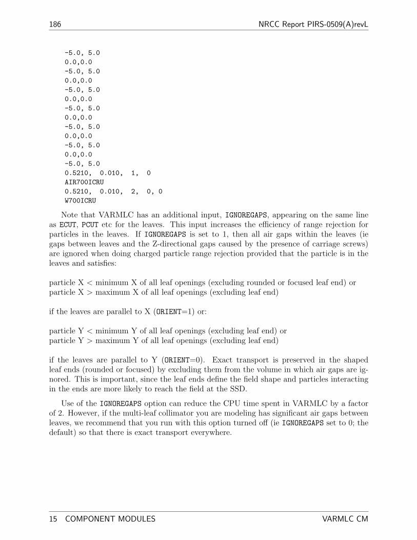
186 NRCC Report PIRS-0509(A)revL
-5.0, 5.00.0,0.0-5.0, 5.00.0,0.0-5.0, 5.00.0,0.0-5.0, 5.00.0,0.0-5.0, 5.00.0,0.0-5.0, 5.00.0,0.0-5.0, 5.00.5210, 0.010, 1, 0AIR700ICRU0.5210, 0.010, 2, 0, 0W700ICRU
Note that VARMLC has an additional input, IGNOREGAPS, appearing on the same lineas ECUT, PCUT etc for the leaves. This input increases the efficiency of range rejection forparticles in the leaves. If IGNOREGAPS is set to 1, then all air gaps within the leaves (iegaps between leaves and the Z-directional gaps caused by the presence of carriage screws)are ignored when doing charged particle range rejection provided that the particle is in theleaves and satisfies:
particle X < minimum X of all leaf openings (excluding rounded or focused leaf end) orparticle X > maximum X of all leaf openings (excluding leaf end)
if the leaves are parallel to X (ORIENT=1) or:
particle Y < minimum Y of all leaf openings (excluding leaf end) orparticle Y > maximum Y of all leaf openings (excluding leaf end)
if the leaves are parallel to Y (ORIENT=0). Exact transport is preserved in the shapedleaf ends (rounded or focused) by excluding them from the volume in which air gaps are ig-nored. This is important, since the leaf ends define the field shape and particles interactingin the ends are more likely to reach the field at the SSD.
Use of the IGNOREGAPS option can reduce the CPU time spent in VARMLC by a factorof 2. However, if the multi-leaf collimator you are modeling has significant air gaps betweenleaves, we recommend that you run with this option turned off (ie IGNOREGAPS set to 0; thedefault) so that there is exact transport everywhere.
15 COMPONENT MODULES VARMLC CM
BEAMnrc Users Manual 187
15.3.16 MLCE
The MLCE CM is used to model multi-leaf collimators specific for Elekta machines. Insteadof specifying a tongue-and-groove, the user specifies the dimensions of interlocking stepstypical of this class of MLC. All leaves have identical cross-sections, and leaf sides are focused(always to Z=0) by tilting each leaf about an axis that runs parallel to the leaf openingdirection and along the centre of its top surface. The entire leaf bank can also be rotated ina plane perpendicular to the leaf opening direction by a user-specified angle. As in VARMLC,the medium beyond the leaves in the direction perpendicular to the leaves defaults to be thesame as the medium in the leaf opening(s) (ie AIR).
This CM was mostly coded by Nick Reynaert at the University of Ghent. There havebeen some modifications of inputs and some small bugs were fixed.
Details of MLCE are shown in Figure 34. All leaves have identical cross-sections, whichare defined using an imaginary “central leaf”. For this leaf, the user specifies the 4 pointsdefining the cross-section (which is symmetric about X=0 if the steps are ignored), X3, ZMIN,X4, ZMAX, the Z positions of the left and right steps, ZSTEPL,ZSTEPR, and the step width,TGW. Note that ZSTEPL must be >ZSTEPR for the steps to fit into one another once theleaves are generated. The central leaf is then duplicated NUM LEAF times, and each leaf isrotated/translated in the X (ORIENT=0) or Y (ORIENT=1) direction. Rotation angle andtranslation distance are determined by user inputs which define the spacing between thecentres of the leaf cross-sections, SPACE, as projected down to SSD and the requirement thatthe leaf sides focus to Z=0. Leaves are first rotated about the X=0 (ORIENT=0) or Y=0(ORIENT=1), Z=ZMIN using:
rotation =
{ATAN
[− (2I − 1)(
SPACE2
) (ZMINSSD
)]for 1≤ I ≤ NUM LEAF
2,
ATAN[(2I − 1)
(SPACE
2
) (ZMINSSD
)]for NUM LEAF
2+ 1 ≤ I ≤ NUM LEAF.
(7)Then they are translated in the X (ORIENT=0) or Y (ORIENT=1) direction using:
translation =
{− (2I − 1)
(SPACE
2
) (ZMINSSD
)for 1≤ I ≤ NUM LEAF
2,
(2I − 1)(
SPACE2
) (ZMINSSD
)for NUM LEAF
2+ 1 ≤ I ≤ NUM LEAF.
(8)Note the restriction that NUM LEAF must be an even number. After the leaves have beenrotated/translated according to the above equations, their cross-sections are symmetric aboutthe Z axis.
The user also has the option to rotate the entire leaf bank about the axis X=0 (ORIENT=0)or Y=0 (ORIENT=1), Z=ZMIN by angle LBROT (which must be specified in radians). Thisrotates the central axis of the leaves (ie the axis along which they are focused) from Z to Z’,as shown in Figure 34. Rotation of the leaves, both individually and of the entire leaf bank,requires automatic resetting of ZMIN and ZMAX, shown as (adjusted) values in the figure.
Figure 34 also shows the two types of leaf ends possible with MLCE. Cylindrical leaf ends(ENDTYPE=0) are defined by the radius, LEAFRADIUS, and Z position, ZCIL, of the cylinderdescribing the ends. Leaf openings are specified by the X (ORIENT=1) or Y (ORIENT=0)coordinates of the cylinder origins for the positive (POS) and negative (NEG) portions of theleaf. Straight leaf ends (ENDTYPE=1) are angled according to the user-input ZFOCUS, and leaf
Last edited 2011/05/09 19:16:55 MLCE CM

188 NRCC Report PIRS-0509(A)revL
Z
X3
X4
ZSTEPRZMINZMAX
ZSTEPL
TGW
X
MLCEcentral leaf X cross−section
duplicatetranslaterotate
ZZRMAX_CM
ZFOCUS
NEG POS
ENDTYPE=0LEAFRADIUS
Y
ENDTYPE=1
X
2 3 4leaf 1
Z’=0
SSD
Z_min_CM
RMAX_CM
Z Z’
SPACE
ZMIN (input)
ZMIN (adjusted)
ZMAX (adjusted)
ZMIN(input)
ZMAX(input)
NEG POS
CIL
Top View
LBROT
RMAX_CMY
Y cross−section
X
MED1MED2
Figure 34: Example MLCE with 8 leaves (NUM LEAF=8) opening in the Y direction(ORIENT=0) and with a leaf bank rotation angle of LBROT. The figure also shows the cross-section of the imaginary “central leaf”, used to create the leaves, and the two possible leafend types: cylindrical (ENDTYPE=0) and straight (ENDTYPE=1). See text for more details.
15 COMPONENT MODULES MLCE CM

BEAMnrc Users Manual 189
openings are specified by the X ORIENT=1) or Y (ORIENT=0) coordinates of the ends of thepositive (POS) and negative (NEG) portions of the leaf at Z=ZMIN.
Note that MLCE input allows you to apply values of POS and NEG to groups of adjacentleaves, which can save tedious input in the case where many adjacent leaves have the sameopening coordinates. See the input description below for more details.
The input format for MLCE and an example input are given below.
CARDS CM_$MLCE**************-1 Dummy line to indicate start of CM
0 RMAX_CM(ICM_$MLCE) (F10.0): Half-width of CM boundary (cm).
1 TITLE_$MLCE (60A1): Title of CM.
2 ORIENT_$MLCE (I5) = 0 for leaves parallel to Y direction= 1 for leaves parallel to X direction
3 NUM_LEAF_$MLCE: Number of leaves. Note: this must be even.
4 ZMIN_$MLCE,ZMAX_$MLCE (2F15.0): upper and lower z coordinatesof leafbank (before tilt, see below)
5 ZSTEPL_$MLCE, ZSTEPR_$MLCE: Z-coordinates of left and right stepin central leaf (an imaginary, unrotated leaf on the Z axis).
6 TGW_$MLCE (F15.0): X (ORIENT_$MLCE=0) or Y (ORIENT_$MLCE=1)width of steps in central leaf (cm).
7 X3_$MLCE, X4_$MLCE (2F15.0): X (ORIENT_$MLCE=0) or Y(ORIENT_$MLCE=1) coordinates of the upper right andlower right corners of central leaf, ignoring steps defined above.
8 SPACE_$MLCE, SSD_$MLCE (2F15.0)
SPACE_$MLCE: distance between centres of adjacent leaves in X(ORIENT_$MLCE=0) or Y (ORIENT_$MLCE=1) directionas projected to SSD_$MLCE (cm).
SSD_$MLCE: distance from Z=0 at which SPACE_$MLCE isdefined (cm).
Leaf numbers I= 1-NUM_LEAF_$MLCE/2 are created by rotating aduplicate of the central leaf about the axis X=0 (ifORIENT_$MLCE=0) or Y=0 (if ORIENT_$MLCE=1),Z=ZMIN_$MLCE by an angle:ARCTAN(-(2I-1)*SPACE_$MLCE/2.*ZMIN_$MLCE/SSD_$MLCE)and then translating it in the X (if ORIENT_$MLCE=0) oror Y (ORIENT_$MLCE=1) direction by a distance
Last edited 2011/05/09 19:16:55 MLCE CM

190 NRCC Report PIRS-0509(A)revL
-(2I-1)*SPACE_$MLCE/2.*ZMIN_$MLCE/SSD_$MLCE
Leaf numbers I= NUM_LEAF_$MLCE/2+1 NUM_LEAF_$MLCE are created byrotating a duplicate of the central leaf about the axis X=0(if ORIENT_$MLCE=0) or Y=0 (if ORIENT_$MLCE=1), Z=ZMIN_$MLCE by:ARCTAN((2I-1)*SPACE_$MLCE/2.*ZMIN_$MLCE/SSD_$MLCE)and then translating it in the X (if ORIENT_$MLCE=0) oror Y (ORIENT_$MLCE=1) direction by a distance(2I-1)*SPACE_$MLCE/2.*ZMIN_$MLCE/SSD_$MLCE
9 LBROT_$MLCE (F15.0): Leaf bank rototian angle (tilt) aboutX=0 (ORIENT_$MLCE=0) or Y=0 (ORIENT_$MLCE=1) and Z=ZMIN_$MLCE(radians). This is applied to the leaves after they have beentranslated/rotated according to SPACE_$MLCE, SSD_$MLCE above.
10 ENDTYPE_$MLCE (I5) : The type of leaf end :0 -- rounded (cylindrical) leaf end and1 -- focused divergent leaf end.
IF ENDTYPE_$MLCE=011 LEAFRADIUS_$MLCE,CIL_$MLCE (2F15.0)
LEAFRADIUS_$MLCE: Radius curvature leaf endsCIL_$MLCE: Z position from which LEAFRADIUS_$MLCE is
defined
IF ENDTYPE_$MLCE=111 ZFOCUS_$MLCE (F15.0): Z position of focal point of leaf ends
Repeat 12 until coordinates of all leaves are defined once. Leavesare numbered 1,2,...NUM_LEAF_$MLCE, where numbering goes from leaf1 to leaf NUM_LEAF_$MLCE. Convention is lower to upper orleft to right depending on ORIENT_$MLCE i.e from negative topositive.
12 NEG_$MLCE, POS_$MLCE, NUM_$MLCE (2F15.0,I5)
NEG_$MLCE: Min. Y (ORIENT_$MLCE=0) or X (ORIENT_$MLCE=1)of a) opening in leaf I at ZMIN_$MLCE (ENDTYPE=1)or b) of origin of cylindrical leaf end (ENDTYPE=0)
POS_$MLCE: Max. Y (ORIENT_$MLCE=0) or X (ORIENT_$MLCE=1)of a) opening in leaf I at ZMIN_$MLCE (ENDTYPE=1)or b) of origin of cylindrical leaf end (ENDTYPE=0)
NUM_$MLCE: Apply NEG_$MLCE and POS_$MLCE to leavesI,...,I+NUM_$MLCE-1. Defaults to 1 if set <=0.Defaults to NUM_LEAF_$MLCE-I+1 if set >NUM_LEAF_$MLCE-I+1.
13 ECUT, PCUT, DOSE_ZONE, IREGION_TO_BIT in opening(s) and
15 COMPONENT MODULES MLCE CM

BEAMnrc Users Manual 191
air gaps (2F15.0,I5)
ECUT, PCUT: Cutoff energies for electrons and photons.DOSE_ZONE: Dose scoring flag, 0 to not score dose
IREGION_TO_BIT: Bit number associated with this region
14 MED_IN (24A1): Medium in opening(s) and air gapsused to set MED_INDEX.
15 ECUT, PCUT, DOSE_ZONE, IREGION_TO_BIT in leaves (2F15.0,I5):
ECUT, PCUT: Cutoff energies for electrons and photons.DOSE_ZONE: Dose scoring flag, 0 to note score dose
IREGION_TO_BIT: Bit number associated with this region
16 MED_IN (24A1): Medium of leaves,used to set MED_INDEX.
Example*******
The following example defines a multi-leaf collimator design basedloosely on that used with the Elekta SLiplus 40 leaf pair.Actual parameters are DIFFERENT - this serves just as a template.Do not attempt to use these parameters for a simulation of the realmachine.
The collimator starts at Z=30 cm and has 40 tungsten leaves openingin the X direction. The leaves are each ~0.4cm wide and 7.0 cmthick. In this example, the leaf openings will form a barbel shapewith its long axis parallel to Y. It will be slightly off-centredue to the leaf bank rotation of -0.01 rads.
Electrons and photons in both the collimator and the opening regionswill be followed down to kinetic energies of 10 keV (ECUT=0.521,PCUT=0.01). Dose deposited in the tungsten leaves will be storedin dose zone 2, and dose deposited in the opening will be storedin dose zone 1.
In this example the numbers are only approximate, more details shouldbe obtained from the vendor26.0, RMAX_CMMLC based on mock 40 leaf pair Elekta SLiplus type of accelerator1, Leaves open in X direction40, 40 leaf paires30.0,37.0, ZMIN,ZMAX34.0, 33.5, ZSTEPL,ZSTEPR0.04, step width
Last edited 2011/05/09 19:16:55 MLCE CM

192 NRCC Report PIRS-0509(A)revL
0.17,0.2, X3, X4 of central leaf1.2, 100.0, leaf centres spaced 1.2 cm apart projected to SSD=100cm-0.01, leaf bank tilt angle (radians)0, ENDTYPE IS CURVED15.0,33.5, curvature radius, zposition cylinder axis curvature-15.0, 15.0, 16-17.0, 17.0, 2-16.0, 16.0, 4-17.0, 17.0, 2-15.0, 15.0, 160.5210, 0.010, 1, 0AIR700ICRU0.5210, 0.010, 2, 0W700ICRU
15 COMPONENT MODULES MLCE CM

BEAMnrc Users Manual 193
15.3.17 DYNVMLC
DYNVMLC is a CM specifically designed to model the Varian Millenium multi-leaf collima-tor. The code is based on VARMLC. The user specifies cross-sections perpendicular to theleaf opening direction for the 3 leaf types (FULL, TARGET and ISOCENTER leaves) foundin the mlc. Each leaf in the leaf bank (usually comprising 120 leaves in all) is assigned atype, with TARGET/ISOCENTER leaves always occuring in pairs. The user also specifies aZ focal point for the leaf sides and either the radius (for cylindrical ends) or Z focal point (forstraight ends) for the leaf ends. Note that DYNVMLC leaf cross sections are more complexthan those in the VARMLC CM.
Unique among the CMs simulating multileaf collimators, DYNVMLC allows the simu-lation of multiple fields (where a field is defined by a complete set of leaf openings) duringa single run. Leaf opening coordinates can be simulated changing while the beam is on(dynamic, or MODE=1, simulation) or while the beam is off (step-and-shoot, or MODE=2, sim-ulation). For these simulations, the user must supply a file containing the leaf opening datafor each field and the relative intensity of each field. Alternatively, DYNVMLC can be usedto simulate a fixed set of leaf opening coordinates for the entire run (static, or MODE=0,simulation).
DYNVMLC was originally coded by Emily Heath at McGill University. There have beensome modifications of inputs and some bugs were fixed.
Figure 35 shows an example DYNVMLC with 8 leaves (NUM LEAF=8) opening in the Ydirection (ORIENT=0). The X cross-sections of the 3 leaf types, along with the dimensionsthat you must specify, are shown in detail at the top. The meanings of the labels are shownin Table 3.
FULL and ISOCENTER leaves extend from ztip to ZMIN+ZTHICK, while TARGET leavesextend from ZMIN to ztip. For each leaf, you must also specify the Z dimensions of a drivingscrew hole (filled with MED3) that spans the entire width of the leaf cross-section. When spec-ifying the cross-sections of each leaf type, the grid lines shown in Figure 35 must not changeorder, however they can overlap. This means, for example, that when specifying the FULLleaf dimensions zt ≤ zg, wt ≤ wtip ≤ wt + wts - wbs, etc. Also, Z positions of tongues andgrooves must allow leaves to fit together in the following combinations: FULL/FULL (ie zt
≤ zg), FULL/TARGET (ie zgFULL ≥ ztTARGET ), TARGET/ISOCENTER (ie zgTARGET
≤ ztISOCENTER), ISOCENTER/TARGET (ie zgISOCENTER ≥ ztTARGET ) and ISOCEN-TER/FULL (ie zgISOCENTER ≥ ztFULL). All of these requirements put fairly tight restric-tions on cross-section dimensions.
Not shown in the leaf cross-sections is the distance, HOLEPOS, between the leaf end andthe end of the driving screw hole in the leaf opening direction. This must also be specifiedfor each leaf type.
Once you have specified the cross-sections for the 3 leaf types, then you must assign atype to each leaf in the leaf bank. Since TARGET/ISOCENTER leaves must always occurin pairs (with the TARGET leaf on the negative X side if ORIENT=0 or on the negativeY side if ORIENT=1), you really only have a choice of two leaf types: 1. FULL leaf or 2.TARGET/ISOCENTER pair. You can also specify the number of adjacent leaves that havethe same type so that you do not have to input the type for each leaf or leaf pair separately.
Last edited 2011/05/09 19:16:55 DYNVMLC CM

194 NRCC Report PIRS-0509(A)revL
ztip zl
zbh
zg
wtip
zt
wt
wg
zth
wbs
zts
zbswts
wl
zts
zbs
zthzbh
zlztip
wts
wbs
wtip
ztipzl
ztzg
zthzbh
zts
zbs
wtip
wt
wg
wts
ztzg
wt wg
zbhzth
wbs
driving screwhole
wl
wl
4 5 6 7 8
ZZRMAX_CM
ZTHICK/2NEG POS
ZFOCUS(2)
NEG POS
ENDTYPE=0 ENDTYPE=1LEAFRADIUS Y
Y
Y cross−sectionRMAX_CM
ZTHICK
ZMIN
ZMIN
START RMAX_CM
X
Y
MED2
MED3
X
leaf 1 2 3
ZFOCUS(1)
START
TARGETFULL ISOCENTER
LEAFGAP
ZMIN
ZTHICK
Z
MED1
LEAFGAP
HOLEPOS HOLEPOS
Top View
DYNVMLC
X cross−sections
Figure 35: Example DYNVMLC with 8 leaves (NUM LEAF=8) opening in the Y direction(ORIENT=0). At the top of the figure are detailed X cross-sections of the 3 leaf types,FULL, TARGET and ISOCENTER, showing the dimensions that the user must input. Thedimension labels are explained in the text below. The Y cross-section shows the two possibleleaf end types: cylindrical (ENDTYPE=0) and straight (ENDTYPE=1).
15 COMPONENT MODULES DYNVMLC CM

BEAMnrc Users Manual 195
Table 3: Meaning of labels in Figure 35.
Leaf Type
FULL TARGET ISOCENTERwidths:wl leaf (excl. tongue) leaf (excl. tongue) leaf (excl. tongue)wt tongue tongue tonguewg groove groove groovewtip tip at top of leaf tip at bottom of leaf tip at top of leafwts top support rail top support rail top support railwbs bottom support rail bottom support rail bottom support railZ positions:ztip top of tip bottom of tip top of tipzl top of leaf bottom of leaf top of leafzt bottom of tongue bottom of tongue top of tonguezg bottom of groove top of groove bottom of groovezth top of driving screw hole top of driving screw hole top of driving screw holezbh bottom of driving screw hole bottom of driving screw hole bottom of driving screw holezts top of support rail top of support rail top of support railzbs bottom of support rail bottom of support rail bottom of support rail
In the example shown in Figure 35, leaves 1,2,7,8 are FULL (type 1) and leaves 3-6 areTARGET/ISOCENTER pairs (type 2).
The X cross-section of the entire leaf bank shows how the different leaf types fit togetherwith interlocking steps and with an air gap between each leaf specified by the LEAFGAP input.The negative-most leaf begins at X=START. All leaf sides are focused on the Z axis at theuser-specified focal point, ZFOCUS(1). The focusing of leaf sides means that leaf widths arenot uniform from leaf top to bottom (although in a realistic case, where the MLC is closeto the SSD and ZFOCUS(1)=0, the variation in widths will be slight), and it is important tonote that all X (ORIENT=0) or Y (ORIENT=1) dimensions that you input (whether they bewidths for the individual leaf types or dimensions relevant to the entire leaf bank, such asLEAFGAP or START) are specified at ZMIN.
The Y cross-section in Figure 35 shows the two possible leaf end types: cylindrical(ENDTYPE=0) and straight focused (ENDTYPE=1). Cylindrical leaf ends have radius LEAFRADIUSwith the origin of the radius at Z=ZMIN+ZTHICK/2 (ie at the mid-point of the leaf thick-ness). The negative and positive dimensions of the opening in a leaf with cylindrical endsare specified at Z=ZMIN+ZTHICK/2. Straight leaf ends are focused to Z=ZFOCUS(2), andthe negative and positive dimensions of the opening are specified at Z=ZMIN. The Y cross-section also shows how the distance from the end of the driving screw hole to the leaf end,HOLEPOS, is defined. In the case of cylindrical ends, it is the distance from the leaf endat Z=ZMIN+ZTHICK/2, while for straight ends, it is the distance from the end at Z=ZMIN.HOLEPOS remains the same for a given leaf type (FULL, TARGET or ISOCENTER) regard-less of the leaf opening dimensions.
Last edited 2011/05/09 19:16:55 DYNVMLC CM
196 NRCC Report PIRS-0509(A)revL
For static (MODE=0, the default) simulations, in which leaf openings are fixed for theentire simulation, the leaf openings coordinates are specified in the GUI or input file in amanner similar to MLC, MLCQ, VARMLC, etc. Note that the user can specify the numberof adjacent leaves that have the same opening dimensions, thus potentially saving input lines.For dynamic (MODE=1) or step-and-shoot (MODE=2) simulations, where multiple treatmentfields are simulated in a single run, however, the user must supply a file of leaf opening data.The format of this file is:
TITLE
NFIELDS
FOR I=1,NFIELDS[
INDEX(I)
NEG, POS, NUM -- repeat until NEG, POS have been defined for all leaves
]
where TITLE is a title line for the file, NFIELDS is the number of treatment fields, INDEX(I)is the index of treatment field I, NEG is the lower Y (ORIENT=0) or X (ORIENT=1) coordinateof the leaf opening, POS is the upper Y or X coordinate of the leaf opening, and NUM is thenumber of adjacent leaves for which NEG and POS apply (defaults to 1 if left blank). Notethat the NEG, POS, NUM line must be repeated until the opening coordinates for all leaves havebeen defined for field I.
The treatment field indices, INDEX(I)’s, are numbers in the range [0,1](with INDEX(I)>INDEX(I-1)) which determine which field is used in a particular history.At the beginning of each history a random number in the range [0,1], RNDM1, is comparedto (INDEX(I),I=1,NFIELDS). The lowest value of I for which INDEX(I)≥RNDM1 is the fieldused in the history. Note that this means that INDEX(I)-INDEX(I-1) is a measure of theprobability, or intensity, of field I. In the case of step-and-shoot (MODE=2) runs, the leafopening coordinates are simply those defined for field I. In the case of dynamic (MODE=1)simulations, however, RNDM1 is used to calculate intermediate opening coordinates betweenfields I and I-1 to simulate leaf coordinates changing while the beam is on. For example, ifNEG(J,I) and NEG(J,I-1) are the lower coordinates of leaf J in fields I and I-1, respectively,then the intermediate lower coordinate used, NEG INT is given by:
NEG INT = NEG(J, I− 1) + (NEG(J, I)− NEG(J, I− 1)) ∗ (RNDM1− INDEX(I− 1))
(INDEX(I)− INDEX(I− 1))(9)
A sample file containing leaf opening data for DYNVMLC is included with the distribu-tion.
Similar to VARMLC, DYNVMLC has an IGNOREGAPS input (appearing on the same lineas ECUT, PCUT etc for the leaves) which can be set to 1 to instruct the code to ignore allair gaps within the leaf bank (ie gaps between leaves and Z-directional gaps caused by thepresence of leaf tips, support rails, etc) and the driving screw holes when doing chargedparticle range rejection provided that the particle is in the leaf medium and:
particle X < minimum X of all leaf openings (excluding rounded or focused leaf end) orparticle X > maximum X of all leaf openings (excluding leaf end)
15 COMPONENT MODULES DYNVMLC CM

BEAMnrc Users Manual 197
if the leaves are parallel to X (ORIENT=1) or:
particle Y < minimum Y of all leaf openings (excluding leaf end) orparticle Y > maximum Y of all leaf openings (excluding leaf end)
if the leaves are parallel to Y (ORIENT=0). Exact transport is preserved in the shapedleaf ends (rounded or focused) by excluding them from the volume in which air gaps anddriving screw holes are ignored. Setting IGNOREGAPS=1 greatly increases the efficiency ofrange rejection in DYNVMLC and can reduce CPU time spent in the CM by a factor of 2.However, if you are concerned that the air gaps and driving screw holes have a significanteffect on the beam field, we recommend that you run with IGNOREGAPS=0 to preserve exacttransport everywhere. Note that in the case of dynamic or step-and-shoot simulations, theminimum and maximum opening coordinates must be recalculated at the beginning of eachhistory.
The input format for DYNVMLC and an example input are given below.
CARDS CM_$DYNVMLC********************-1 Dummy line to indicate start of CM
0 RMAX_CM(ICM_$DYNVMLC) (F10.5): Half-width of CM boundary (cm).
1 TITLE_$DYNVMLC (60A1): Title of CM.
2 ORIENT_$DYNVMLC, NGROUP_$DYNVMLC, MODE_$DYNVMLC (3I5)
ORIENT_$DYNVMLC = 0 for leaves parallel to Y direction= 1 for leaves parallel to X direction
NGROUP_$DYNVMLC = number of groups of adjacent leaves whereall leaves in a group are:1. FULL leaves2. TARGET/ISOCENTER pairs with TARGET leaf
on the -X (ORIENT=0) or -Y (ORIENT=1) sideNGROUP_$DYNVMLC defaults to 3 if set <=0
MODE_$DYNVMLC = 0 for single setting of leaf openings (staticfield)
= 1 for dynamic mlc delivery--simulated leafmovement while beam is on
= 2 for step-and-shoot delivery--beam off whileleaf positions change
3 ZMIN_$DYNVMLC (F15.0): Z of top of MLC (excluding airgap)
4 ZTHICK_$DYNVMLC (F15.0): Thickness of the leaves ( z-axis (cm))
5 LEAFWIDTH_$DYNVMLC(1), WTONGUE_$DYNVMLC(1), WGROOVE_$DYNVMLC(1),WTIP_$DYNVMLC(1), WRAILTOP_$DYNVMLC(1), WRAILBOT_$DYNVMLC(1),ZTIP_$DYNVMLC(1), ZLEAF_$DYNVMLC(1), ZTONGUE_$DYNVMLC(1),
Last edited 2011/05/09 19:16:55 DYNVMLC CM

198 NRCC Report PIRS-0509(A)revL
ZGROOVE_$DYNVMLC(1), ZHOLETOP_$DYNVMLC(1), ZHOLEBOT_$DYNVMLC(1),HOLEPOS_FULL_$DYNVMLC, ZRAILTOP_$DYNVMLC(1), ZRAILBOT_$DYNVMLC(1)
(15F15.0)
For a FULL type leaf (all dimensions in cm--all widths areprojected back to ZMIN_$DYNVMLC):
LEAFWIDTH_$DYNVMLC(1): Width of leaf (not including tongue)WTONGUE_$DYNVMLC(1): Width of tongueWGROOVE_$DYNVMLC(1): Width of groove
WTIP_$DYNVMLC(1): Width of tip at top of leafWRAILTOP_$DYNVMLC(1): Width of top of support railWRAILBOT_$DYNVMLC(1): Width of bottom of support rail
ZTIP_$DYNVMLC(1): Z at which tip at top of leaf beginsZLEAF_$DYNVMLC(1): Z of top of leaf
ZTONGUE_$DYNVMLC(1): Z of bottom of tongueZGROOVE_$DYNVMLC(1): Z of bottom of groove
ZHOLETOP_$DYNVMLC(1): Z of top of driving screw holeZHOLEBOT_$DYNVMLC(1): Z of bottom of driving screw holeHOLEPOS_FULL_$DYNVMLC: Distance of hole from leaf tipZRAILTOP_$DYNVMLC(1): Z of top of support railZRAILBOT_$DYNVMLC(1): Z of bottom of support rail
Note: Z positions are input in order of increasing Z. ThusZLEAF_$DYNVMLC(1)>=ZTIP_$DYNVMLC(1), etc. See the BEAMmanual or GUI help for restrictions on widths.
6 LEAFWIDTH_$DYNVMLC(2), WTONGUE_$DYNVMLC(2), WGROOVE_$DYNVMLC(2),WTIP_$DYNVMLC(2), WRAILTOP_$DYNVMLC(2), WRAILBOT_$DYNVMLC(2),ZRAILTOP_$DYNVMLC(2), ZRAILBOT_$DYNVMLC(2), ZHOLETOP_$DYNVMLC(2),ZHOLEBOT_$DYNVMLC(2), HOLEPOS_TAR_$DYNVMLC, ZTONGUE_$DYNVMLC(2),ZGROOVE_$DYNVMLC(2), ZLEAF_$DYNVMLC(2), ZTIP_$DYNVMLC(2) (15F15.0)
For a TARGET type leaf (all dimensions in cm--all widths areprojected back to ZMIN_$DYNVMLC):
LEAFWIDTH_$DYNVMLC(2): Width of leaf (not including tongue)WTONGUE_$DYNVMLC(2): Width of tongueWGROOVE_$DYNVMLC(2): Width of groove
WTIP_$DYNVMLC(2): Width of tip at bottom of leafWRAILTOP_$DYNVMLC(2): Width of top of support railWRAILBOT_$DYNVMLC(2): Width of bottom of support railZRAILTOP_$DYNVMLC(2): Z of top of support railZRAILBOT_$DYNVMLC(2): Z of bottom of support railZHOLETOP_$DYNVMLC(2): Z of top of driving screw holeZHOLEBOT_$DYNVMLC(2): Z of bottom of driving screw holeHOLEPOS_TAR_$DYNVMLC: Distance of hole from leaf tipZTONGUE_$DYNVMLC(2): Z of bottom of tongue
15 COMPONENT MODULES DYNVMLC CM

BEAMnrc Users Manual 199
ZGROOVE_$DYNVMLC(2): Z of top of grooveZLEAF_$DYNVMLC(2): Z of bottom of leafZTIP_$DYNVMLC(2): Z of bottom of tip at bottom of leaf
Note: Z positions are input in order of increasing Z. ThusZLEAF_$DYNVMLC(1)>=ZTIP_$DYNVMLC(1), etc. See the BEAMmanual or GUI help for restrictions on widths.
7 LEAFWIDTH_$DYNVMLC(3), WTONGUE_$DYNVMLC(3), WGROOVE_$DYNVMLC(3),WTIP_$DYNVMLC(3), WRAILTOP_$DYNVMLC(3), WRAILBOT_$DYNVMLC(3),ZTIP_$DYNVMLC(3), ZLEAF_$DYNVMLC(3), ZTONGUE_$DYNVMLC(3),ZGROOVE_$DYNVMLC(3), ZHOLETOP_$DYNVMLC(3), ZHOLEBOT_$DYNVMLC(3),HOLEPOS_ISO_$DYNVMLC, ZRAILTOP_$DYNVMLC(3), ZRAILBOT_$DYNVMLC(3)
(15F15.0)
For a ISOCENTER type leaf (all dimensions in cm--all widths areprojected back to ZMIN_$DYNVMLC):
LEAFWIDTH_$DYNVMLC(3): Width of leaf (not including tongue)WTONGUE_$DYNVMLC(3): Width of tongueWGROOVE_$DYNVMLC(3): Width of groove
WTIP_$DYNVMLC(3): Width of tip at top of leafWRAILTOP_$DYNVMLC(3): Width of top of support railWRAILBOT_$DYNVMLC(3): Width of bottom of support rail
ZTIP_$DYNVMLC(3): Z at which tip at top of leaf beginsZLEAF_$DYNVMLC(3): Z of top of leaf
ZTONGUE_$DYNVMLC(3): Z of top of tongueZGROOVE_$DYNVMLC(3): Z of bottom of groove
ZHOLETOP_$DYNVMLC(3): Z of top of driving screw holeZHOLEBOT_$DYNVMLC(3): Z of bottom of driving screw holeHOLEPOS_ISO_$DYNVMLC: Distance of hole from leaf tipZRAILTOP_$DYNVMLC(3): Z of top of support railZRAILBOT_$DYNVMLC(3): Z of bottom of support rail
Note: Z positions are input in order of increasing Z. ThusZLEAF_$DYNVMLC(1)>=ZTIP_$DYNVMLC(1), etc. See the BEAMmanual or GUI help for restrictions on widths.
Note: 1. For TARGET and ISOCENTER leaves to fit together,ZTONGUE_$DYNVMLC(3)>=ZGROOVE_$DYNVMLC(2) andZTONGUE_$DYNVMLC(2)<=ZGROOVE_$DYNVMLC(3).
2. For TARGET and FULL leaves to fit together (FULLleaf on -X [ORIENT=0] or -Y [ORIENT=1] side of TARGETleaf only) ZTONGUE_$DYNVMLC(2)<=ZGROOVE_$DYNVMLC(1)
3. For ISOCENTER and FULL leaves to fit together (FULLleaf on +X [ORIENT=0] or +Y [ORIENT=1] side of ISOCENTERleaf only) ZTONGUE_$DYNVMLC(1)<=ZGROOVE_$DYNVMLC(3)
Last edited 2011/05/09 19:16:55 DYNVMLC CM

200 NRCC Report PIRS-0509(A)revL
Repeat 8 NGROUP_$DYNVMLC times
8 NUM_LEAF_$DYNVMLC(I), LEAFTYPE (2I5)
NUM_LEAF_$DYNVMLC(I): Number of adjacent leaves in group ILEAFTYPE: Type of leaf in group I.
Set to: 1 for FULL leaves2 for TARGET/ISOCENTER pair withTARGET leaf on the -X (ORIENT=0)or -Y (ORIENT=1) side
Note: If LEAFTYPE is 2, then you must have an even numberof leaves in the group.
9 START_$DYNVMLC (F15.0) : the start position (cm) wrt the CAX ofleaf 1 as projected to ZMIN_$DYNVMLC.
10 LEAFGAP_$DYNVMLC (F15.5) : The width of the interleaf air gapat ZMIN_$DYNVMLC.
Note restriction: LEAFGAP_$DYNVMLC<=WTONGUE_$DYNVMLC(1,2,3),
11 ENDTYPE_$DYNVMLC (I5) : The type of leaf end :0 -- rounded leaf end and1 -- focused divergent leaf end.
12 ZFOCUS_$DYNVMLC (F15.5) : Focal point on Z-axis of leaf ends(i.e. imaginary lines drawn extending the slopesof leaf ends will all intersect the Z-axisat this point) - chosen if ENDTYPE_$DYNVMLC = 1.
Note restriction: ZFOCUS_$DYNVMLC(1) < ZMIN_$DYNVMLC or> ZMIN_$DYNVMLC + ZTHICK_$DYNVMLC
LEAFRADIUS_$DYNVMLC (F15.5) : Radius of the leaf end ifENDTYPE_$DYNVMLC = 0. This must be greaterthan or equal to half the leaf thickness.
13 ZFOCUS_$DYNVMLC(1) (F15.5): Focal point on Z-axis of leaf sidesimaginary lines drawn extending the slopes ofthe leaf sides will all intersect the Z-axisat this point)
Note restriction: ZFOCUS_$DYNVMLC(1) < ZMIN_$DYNVMLC or> ZMIN_$DYNVMLC + ZTHICK_$DYNVMLC
For focused ends the leaf position is definedat ZMIN_$DYNVMLC; for rounded at ZMIN_$DYNVMLC +
15 COMPONENT MODULES DYNVMLC CM
BEAMnrc Users Manual 201
0.5*ZTHICK_$DYNVMLC (ie center of the leaf in z)
If MODE_$DYNVMLC=0 (static field):
Repeat 14a until opening coordinates of all leaves are defined once.Leaves are numbered 1,2,...TOT_LEAF_$DYNVMLC, where numbering goes fromleaf 1 to leaf TOT_LEAF_$DYNVMLC. Convention is lower to upper orleft to right depending on ORIENT_$DYNVMLC i.e from negative topositive. Note that for dynamic or step-and-shoot simulations, theseare the default coordinates, used unless specified otherwise in thefile of leaf opening data input in line 14a (see below).
14a NEG_$DYNVMLC, POS_$DYNVMLC, NUM_$DYNVMLC (2F15.5,I5)
NEG_$DYNVMLC: Min. Y (ORIENT_$DYNVMLC=0) or X (ORIENT_$DYNVMLC=1)of front opening in leaf I (ie the opening atZMIN_$DYNVMLC) if ENDTYPE=1, or of rounded endof leaf I if ENDTYPE=0.
POS_$DYNVMLC: Max. Y (ORIENT_$DYNVMLC=0) or X (ORIENT_$DYNVMLC=1)of front opening in leaf I if ENDTYPE=1, or ofrounded end of leaf I if ENDTYPE=0.
NUM_$DYNVMLC: Apply NEG_$DYNVMLC and POS_$DYNVMLC to leavesI,...,I+NUM_$DYNVMLC-1. Defaults to 1 if set <=0.Defaults to TOT_LEAF_$DYNVMLC-I+1 if set >TOT_LEAF_$DYNVMLC-I+1.
If MODE_$DYNVMLC=1 or 2 (dynamic delivery or step-and-shoot delivery):
14b mlc_file (A80)
mlc_file: The full name of the file containing leaf openingdata. The format of the file contents is as follows:
MLC_TITLE (A80)NFIELDS_$DYNVMLC (I10)FOR I=1,NFIELDS_$DYNVMLC[INDEX_$DYNVMLC(I) (F15.0)NEG_$DYNVMLC, POS_$DYNVMLC, NUM_$DYNVMLC (2F15.0,I5) -- repeat this
line untilcoordinatesfor all leaveshave beendefined forfield I.
]
where:
MLC_TITLE: A title line
Last edited 2011/05/09 19:16:55 DYNVMLC CM

202 NRCC Report PIRS-0509(A)revL
NFIELDS_$DYNVMLC: Total number of fieldsINDEX_$DYNVMLC(I): Index of field I. 0 <= INDEX_$DYNVMLC(I) <= 1 and
INDEX_$DYNVMLC(I) > INDEX_$DYNVMLC(I-1). Thisnumber is compared to a random number on (0,1) atthe start of each history; if the random number is<= INDEX_$DYNVMLC(I), then field I is used.
NEG_$DYNVMLC: Min. Y (ORIENT_$DYNVMLC=0) or X (ORIENT_$DYNVMLC=1)of front opening in leaf (ie the opening atZMIN_$DYNVMLC) if ENDTYPE=1, or of rounded endof leaf if ENDTYPE=0 for leaf J in field I.
POS_$DYNVMLC: Max. Y (ORIENT_$DYNVMLC=0) or X (ORIENT_$DYNVMLC=1)of front opening in leaf if ENDTYPE=1, or ofrounded end of leaf if ENDTYPE=0 for leaf J infield I.
NUM_$DYNVMLC: Apply NEG_$DYNVMLC and POS_$DYNVMLC to leavesJ,...,J+NUM_$DYNVMLC-1. Defaults to 1 if set <=0.Defaults to TOT_LEAF_$DYNVMLC-J+1 if set >TOT_LEAF_$DYNVMLC-J+1.
Note that the inputs NEG_$DYNVMLC, POS_$DYNVMLC and NUM_$DYNVMLC havethe same meanings as in 14a (static field inputs) but that they mustnow be repeated for every field I.
15 ECUT, PCUT, DOSE_ZONE, IREGION_TO_BIT in opening(s) andair gaps (2F15.5,2I5)
ECUT, PCUT: Cutoff energies for electrons and photons.DOSE_ZONE: Dose scoring flag, 0 to not score dose
IREGION_TO_BIT: Bit number associated with this region
16 MED_IN (24A1): Medium in opening(s) and air gapsused to set MED_INDEX.
17 ECUT, PCUT, DOSE_ZONE, IREGION_TO_BIT in leaves, IGNOREGAPS_$DYNVMLC(2F15.0,3I5):
ECUT, PCUT: Cutoff energies for electrons and photons.DOSE_ZONE: Dose scoring flag, 0 to note score dose
IREGION_TO_BIT: Bit number associated with this regionIGNOREGAPS: If set to 1, ignore all air gaps and driving screw
holes when doing rangerejection in leaf material when the particle X positionis < min X of all leaf openings (not including leafends) or > max X of leaf openings (not including ends)(ORIENT_$DYNVMLC=1) or if the particle Y positionis < min Y of all leaf openings (not including leafends) or > max Y of leaf openings (not including ends)(ORIENT_$DYNVMLC=0). This approximation is designedto make range rejection more efficient deep in the
15 COMPONENT MODULES DYNVMLC CM
BEAMnrc Users Manual 203
leaves, while still preserving accurate transportin the leaf ends. Note that if you have significantair gaps between leaves or are concerned with theeffects of the driving screw holes it is recommendedthat you not use this option (ie run with the defaultsetting of 0).
18 MED_IN (24A1): Medium of leaves,used to set MED_INDEX.
19 ECUT, PCUT, DOSE_ZONE, IREGION_TO_BIT in driving screw holes(2F15.5,2I5):
ECUT, PCUT: Cutoff energies for electrons and photons.DOSE_ZONE: Dose scoring flag, 0 to note score dose
IREGION_TO_BIT: Bit number associated with this region
20 MED_IN (24A1): Medium in driving screw holes,used to set MED_INDEX.
Example*******
The following example defines a multi-leaf tungsten collimator designbased loosely on that used with the Varian Millenium MLC.Actual parameters are DIFFERENT - this serves just as a template.Do not attempt to use these parameters for a simulation of the realmachine.
The collimator starts at Z=48.25 cm and has 60 tungsten leaves openingin the X direction. Leaves 1-10 and 51-60 are FULL and leaves 11-50 areTARGET/ISOCENTER pairs. The Z focus of the leaf sides is at Z=0 cmwhich is the position of the source. The leaf ends are rounded with aradius of 8 cm. In this example, leaf opening coordinates are chosen to
create a square of width ~ 2cm centred on the beam axis.
Electrons and photons in both the collimator and the opening regionswill be followed down to kinetic energies of 189 keV (ECUT=0.7,PCUT=0.01). Dose deposited in the tungsten leaves will be storedin dose zone 2, and dose deposited in the opening will be storedin dose zone 1.
20.5, RMAXCL21X - Millenium MLC1, 3, ORIENT, NGROUP48.25, ZMIN6.7, ZTHICK0.5, 0.04, 0.04, 0.1354, 0.3252, 0.1227, 48.25, 48.533, 51.524, 51.732,52.98, 53.28, 2, 54.5474, 54.812, FULL leaf
Last edited 2011/05/09 19:16:55 DYNVMLC CM

204 NRCC Report PIRS-0509(A)revL
0.25, 0.04, 0.04, 0.0929, 0.1371, 0.1371, 48.345, 48.6096, 49.5277,49.8277, 2, 51.625, 51.627, 54.7, 54.746, TARGET leaf
0.25, 0.04, 0.04, 0.0354, 0.1285, 0.1235, 48.412, 48.531, 51.631, 51.732,53.3293, 53.6293, 2, 54.5474, 54.812, ISOCENTER leaf
10, 1, FULL leaves40, 2, TARGET/ISOCENTER pairs10, 1, FULL leaves-10.2, START0.006, LEAFGAP0, ENDTYPE8, ZFOCUS or RADIUS of leaf ends0, ZFOCUS of leaf sides0, 0, 26-1.0, 1.0, 80,0,260.7, 0.01, 1, 0,AIR521ICRU0.7, 0.01, 2, 0, 0,W521ICRU0.7, 0.01, 3, 0,AIR521ICRU
15 COMPONENT MODULES DYNVMLC CM

BEAMnrc Users Manual 205
15.3.18 MESH
The MESH CM models a single-layer wire mesh placed perpendicular to the beam directionin the path of the beam. Details are shown in Figure 36 below.
MESH
beam axis (Z)
Y
RMAX_CM(ICM)
X−Section along Y−A xis
AIRMED2Z_min_CM (ICM+1)
Z_min_CM (ICM)
AIR
XTOTAL
ZMIN
WIRE_THICK
airgap
RMAX_CM(ICM)
Top View
MED2
AIR
AIR
XTOTAL
YTOTAL
XINNER
YINNER
WIRE_WIDTH
beam axis (Z)
X
Y
WIRE_WIDTH
cell boundaries
Figure 36: A MESH component module. The top view shows the identical rectangular air“holes”, each with user-input dimensions XINNER and YINNER, separated from each other andthe edge of the mesh by wire of user-input width, WIRE WIDTH. The outer boundaries of themesh are defined by half- widths XTOTAL and YTOTAL input by the user. Note that there isalways one air hole centred on the beam axis. The top view also shows that a mesh “cell” isa single air hole plus half of the wire surrounding it. From a coding point of view, the mesh ismade up of adjacent cells which behave identically with respect to particle transport. Thusthe code actually only models one cell (the central one), and particles are translated fromouter cells to their equivalent positions in this cell before transport. If the user-input valuesof XTOTAL and/or YTOTAL happen to cut across cells, the outer boundaries are automaticallyadjusted to accommodate these cells. The cross-section along the Y-axis shows the Z positionof the front of the mesh, ZMIN, and the thickness of the mesh, WIRE THICK, both input bythe user. Note that it is possible to have an air gap above the mesh. For dose scoring andbit setting purposes, the wire is considered a single region, and the air in the holes and anyair surrounding the mesh (excluding the air gap) are considered another region.
Last edited 2011/05/09 19:16:55 MESH CM

206 NRCC Report PIRS-0509(A)revL
The input format for MESH and an example input are given below.
CARDS CM_$MESH (MESH: Rev 1.4)**************
-1 dummy line (filled with ****) read in main
0 RMAX_CM outer boundary for CM - 1/2 side of square(read in main)
1 TITLE_$MESH (60A1): Title of CM.
2 ZMIN_$MESH (F10.0): Z position of front of MESH (excluding airgap).
3 X_AIR_WIDTH_$MESH, Y_AIR_WIDTH_$MESH, WIRE_WIDTH_$MESH,WIRE_THICK_$MESH (4F15.0):
X_AIR_WIDTH_$MESH: X width of each air region in mesh (cm)Y_AIR_WIDTH_$MESH: Y width of each air region in mesh (cm)
Y_AIR_WIDTH_$MESH defaults toX_AIR_WIDTH_$MESH if it is set to 0.
WIRE_WIDTH_$MESH: Width of wire in the mesh (cm)WIRE_THICK_$MESH: Thickness of wire in the mesh (cm)
Note restrictions: X_AIR_WIDTH_$MESH,Y_AIR_WIDTH_$MESH,WIRE_WIDTH_$MESH must all be >= 0.0001 cm
4 XTOTAL_$MESH, YTOTAL_$MESH (2F15.0):
XTOTAL_$MESH: Half-width of outer X dimension of mesh (cm)YTOTAL_$MESH: Half-width of outer Y dimension of mesh (cm)
Note: XTOTAL_$MESH,YTOTAL_$MESH default to RMAX_CM if set to 0Also, if they fall within mesh cells (individual air regions +
1/2 of the wire surrounding them) they are pushed outto include those cells.
5 ECUT,PCUT,DOSE_ZONE,IR_TO_BIT for air inside andsurrounding mesh (2F15.0,2I5):
ECUT, PCUT: Cutoff energies for electrons and photons.DOSE_ZONE: Dose scoring flag, 0 to not score dose
IREGION_TO_BIT: Bit number associated with these regions
6 ECUT,PCUT,DOSE_ZONE,IR_TO_BIT in local region 2 (wire region)(2F15.0,2I5):
ECUT, PCUT: Cutoff energies for electrons and photons.DOSE_ZONE: Dose scoring flag, 0 to not score dose
IREGION_TO_BIT: Bit number associated with this region
15 COMPONENT MODULES MESH CM

BEAMnrc Users Manual 207
7 MED_IN (24A1): medium of local region 2 (wire), used to setMED_INDEX
Example*******
The following input example describes a lead mesh placed at Z=100 cmin a beam. The mesh is 0.0299 cm thick, has square air regionswith dimensions 0.2159x0.2159cm, and the lead wire separating the airregions is 0.0381cm wide. Although the RMAX_CM is 10cm, the outerboundary of the mesh itself, as input, is a 6x6cm square. MESHautomatically adjusts this boundary to 6.2421x6.2421cm to accommodateexactly 49 mesh cells (air regions + half of the wire widthsurrounding them) in the X and Y directions plus the extra half-thicknessof wire surrounding the entire mesh and not belonging to any cell.
ECUT and PCUT in all regions are set to 0.521MeV and 0.01MeVrespectively. Air regions (cell air + air surrounding mesh) willhave dose scored in zone 1 and is associated with bit # 1. Thelead wire has dose scored in zone 2 and is associated with bit # 2.
Note that MESH cannot be the first CM in a simulation, and theexample given here must be preceeded by at least an airgap modelledby another type of CM.
10.00000, Outer boundarylead mesh: 0.0381cm with 0.2159cm air100.00.2159, 0.0, 0.0381, 0.0299, depth ensures equal mass as circle6.0, 6.0, outer boundary fills entire beam0.521, 0.01, 1, 1, air is bit 10.521, 0.01, 2, 2, wire is bit 2PB700ICRU
Last edited 2011/05/09 19:16:55 MESH CM

208 NRCC Report PIRS-0509(A)revL
15.3.19 MIRROR
MIRROR is used for a mirror in the accelerator. It can have arbitrary angle < 85 degreeswith respect to the Z axis (for angles between 85 and 90 degrees, approximate using SLABS).The mirror portion itself can be made up of an arbitrary number of layers having differentthicknesses and media. MIRROR has square symmetry.
Z_min_CM (ICM)
Z_min_CM (ICM+1)
RMAX_CM(ICM)
Central Axis
MIRRORAIR
MED1
MED2
MED4
MED3
ZMIN
ZTHICK
XBMIN
XFMIN
DTHICK(1) DTHICK(2)
Figure 37: MIRROR example made up of 2 layers (N=2). The angle of the mirror withrespect to the Z-axis is determined by XFMIN and XBMIN, the positions of the front face(layer 1) of the mirror, and ZTHICK thickness of the mirror in the Z-direction. This anglemust be > 5 degrees. The thickness of layer i of the mirror is given by DTHICK(i). Notethat layer i+1 of the mirror is flush with the right-most face of layer i. Thus, it is possibleto specify a mirror where some layers are out of the path of the beam. It is even possible tospecify XFMIN and XBMIN so that the front face of the mirror (the front face of layer 1) is outof the path of the beam; BEAMnrc checks for this and gives a warning message. The mirrorextends to +−RMAX CM in the Y-direction. The media in front of and behind the mirror,MED4 and MED3 in the figure, will usually be air but need not be.
15 COMPONENT MODULES MIRROR CM

BEAMnrc Users Manual 209
The input format for MIRROR, and an example of input file are given as follows.
CARDS CM_$MIRROR**************
-1 Dummy line to indicate start of CM.
0 RMAX_CM(ICM_$MIRROR) (F10.0): Half-width of CM boundary (cm).
1 TITLE_$MIRROR (60A1): Title of CM.
2 ZMIN_$MIRROR,ZTHICK_$MIRROR (2F15.0):
ZMIN_$MIRROR: Distance from front of CM(excluding air gap) toref plane(Z=0).
ZTHICK_$MIRROR: Z-direction span.
3 XFMIN_$MIRROR, XBMIN_$MIRROR (2F15.0):
XFMIN_$MIRROR: X value at which front face of mirrorintersects ZMIN_$MIRROR.
XBMIN_$MIRROR: X value at which front face of mirrorintersects ZMIN_$MIRROR + ZTHICK_$MIRROR.
Note restriction:5 degrees<ATAN(ZTHICK_$MIRROR/(XFMIN_$MIRROR-XBMIN_$MIRROR)<90 degrees
4 N_$MIRROR, (I10): Number of layers
Repeat 5 for I=1,N_$MIRROR
5 DTHICK_$MIRROR(I) (F15.0): Thickness of layer I in mirror,in cm. Layer 1 is the front faceof the mirror.
Repeat 6 and 7 for I=1,N_$MIRROR.
6 ECUT, PCUT,DOSE_ZONE, IREGION_TO_BIT (2F15.0, 2I5): for each layer
ECUT, PCUT: Cutoff energies for electrons and photons inlayer I.
DOSE_ZONE: Dose scoring flag in layer I.IREGION_TO_BIT: bit to associate local region of layer I with
7 MED_IN (24A1): Medium of layer I, used to set MED_INDEX.
8 ECUT, PCUT, DOSE_ZONE, IREGION_TO_BIT in region behind mirror(2F15.0,2I5):
ECUT, PCUT: Cutoff energies for electrons and photons.
Last edited 2011/05/09 19:16:55 MIRROR CM

210 NRCC Report PIRS-0509(A)revL
DOSE_ZONE: Dose scoring flag, 0 to score dose deposited in itIREGION_TO_BIT: bit to associate local region with
9 MED_IN (24A1): Medium of local region behind the mirror,used to set MED_INDEX.
10 ECUT, PCUT, DOSE_ZONE, IREGION_TO_BIT in region in front ofmirror(2F15.0,2I5):
ECUT, PCUT: Cutoff energies for electrons and photons.DOSE_ZONE: Dose scoring flag, 0 to score dose deposited in it
IREGION_TO_BIT: bit to associate local region with
11 MED_IN (24A1): Medium of region in front of mirror,used to set MED_INDEX.
Example*******
The following describes a mirror composed of 1 AL slab.The front face of the mirror intersects the front of theCM (excluding any airgap) at X=3cm and the back of the CM at X=-3cm.The mirror starts at 19.7cm and is 2cm in the z-direction.The thickness of the AL slab is 0.00508cm.Note that thickness is measured perpendicular to theface of the mirror. AIR is both in front of and behindthe AL mirror. No dose is scored in this example.
10.00 RMAX_CMMIRROR : z=19.5074 downstream, original, dif overlap19.70, 2.03.0, -3.010.005080.0, 0.0, 0, 0AL0.0, 0.0, 0, 0AIR0.0, 0.0, 0, 0AIR
15 COMPONENT MODULES MIRROR CM

BEAMnrc Users Manual 211
15.3.20 XTUBE
A CM, which must be the first CM, for simulating an x-ray tube. XTUBE is actually similarin geometry to MIRROR. However, unlike MIRROR, XTUBE is usually the first CM in abeam model, and the source beam is usually incident on XTUBE from the side. The secondCM may be any of the available CMs with a central opening serving as the exit window ofthe x-ray tube. The target of the xtube may have an arbitrary number of layers, each witha different thickness and medium. XTUBE has square symmetry.
Z_min_CM (ICM)
Z_min_CM (ICM+1)
RMAX_CM(ICM)
Central Axis
XTUBE
Beamdirection
MED3 (Front)
ZMIN
ZTHICK
ANGLEI
DTHICK(1)DTHICK(1)
DTHICK(2)
MED1
MED2MED4 (Holder)
Figure 38: XTUBE component module with 2 layers in the target (N=2). The angle of thetarget relative to the Z-axis is given by ANGLEI. The thickness of a target layer i is given byDTHICK(i). The target is positioned so that the front of the target (layer 2 in the figure)intersects with the beam at the central (Z) axis. Target layers are arranged with the frontof layer i-1 flush with the back of layer i. The target and target holder extend to ± RMAX CM
in the Y-direction. MED3 in the figure above would usually be air or vacuum, but could beany material. MED4 specifies the material of the target holder.
Last edited 2011/05/09 19:16:55 XTUBE CM

212 NRCC Report PIRS-0509(A)revL
The input format for XTUBE and a sample input are given below.
CARDS CM_XTUBE (XTUBE SID: 2.5)**************
-1 Dummy line to indicate start of CM.
0 RMAX_CM(ICM_$XTUBE) (F10.0): Half-width of CM boundary (cm).
1 TITLE_$XTUBE (60A1): Title of CM.
2 ZMIN_$XTUBE,ZTHICK_$XTUBE (2F15.0):
ZMIN_$XTUBE: Distance from front of CM to reference plane(Z=0).ZTHICK_$XTUBE: Thickness of xtube in Z-direction.
Note that there will usually be no air gap at the front ofthis CM.
3 ANGLEI (F15.0): Angle between the target surfaceand Z-axis (in degrees >= 0. and <75.)
4 N_$XTUBE, I_XTRA_$XTUBE (I5):
N_$XTUBE: Number of layers in the target
Repeat 5-7 for I=N_$XTUBE,N_$XTUBE-1,...,1(in XTUBE the first layer of the target is I=N_$XTUBE)
5 DTHICK_$XTUBE(I), I_XTRA_$XTUBE (F15.0,I5)
DTHICK_$XTUBE(I): Thickness of layer I (cm)I_XTRA_$XTUBE: Set to 1 if the layer has an extra central region
(only input for the outermost target layer)
6 ECUT, PCUT,DOSE_ZONE, IREGION_TO_BIT (2F15.0,2I5):
ECUT, PCUT: Cutoff energies for electron and photon transportof layer I.
DOSE_ZONE: Dose scoring flag of layer I.IREGION_TO_BIT: Bit setting of region # corresponding to layer I.
7 MED_IN (24A1): Medium of layer I
Note that inputs 8-10 below are only required if I_XTRA_$XTUBE=1(i.e. the outermost target layer has an extra central region)
8 WXTRA_$XTUBE, HXTRA_$XTUBE (2F15.0):
15 COMPONENT MODULES XTUBE CM

BEAMnrc Users Manual 213
WXTRA_$XTUBE: Width of extra central region in layerN_$XTUBE (cm).
HXTRA_$XTUBE: Height of extra central region in layerN_$XTUBE (cm).
9 ECUT, PCUT,DOSE_ZONE, IREGION_TO_BIT (2F15.0,2I5):
ECUT, PCUT: Cutoff energies for electron and photon transportin extra central region of layer N_$XTUBE.
DOSE_ZONE: Dose scoring flag of extra central region.IREGION_TO_BIT: Bit setting of extra central region.
10 MED_IN (24A1): Medium of extra central region.
11 ECUT, PCUT, DOSE_ZONE, IREGION_TO_BIT (2F15.0,2I5): for region infront of target
ECUT, PCUT: Cutoff energies for electron and photon transportin front of target
DOSE_ZONE: Dose scoring flag for this region.IREGION_TO_BIT: Bit setting of region # corresponding to this one.
12 MED_IN (24A1): Medium in front of target
13 ECUT, PCUT, DOSE_ZONE, IREGION_TO_BIT (2F15.0,2I5): for target holder.
ECUT, PCUT: Cutoff energies for electron and photon transportin target holder.
DOSE_ZONE: Dose scoring flag for target holder.IREGION_TO_BIT: Bit setting of region for target holder.
14 MED_IN (24A1): Medium of target holder
Example*******
The following example describes a tungsten target, 1mm thick,mounted on a copper holder. The target is angled at 22 degreeswith respect to the z-axis. It spans 2cm in the z direction.The medium in front of the target is AIR.ECUT and PCUT for all regions are set to 0.521, 0.01 respectively.Note that the input file specifies the target to start at 10cmfrom the reference plane; if Z_min_CM(1) is not 10cm and XTUBEis the first CM in the beam, the code will autumatically reset thetarget to start at Z_min_CM(1).
10.0 RMAX_CMXTUBE: z=10 cm, 1mm Tungsten target(1 slab), copper holder, 22 degrees10.0, 2.0; distance to reference plane = 10 cm, total thickness=2 cm
Last edited 2011/05/09 19:16:55 XTUBE CM

214 NRCC Report PIRS-0509(A)revL
22.0; angle = 22 degrees1; 1 slab in the target0.1; thickness of the slab = 0.1 cm0.521, 0.01, 0, 2; ECUT,PCUT,DOSE_ZONE,IREGION_TO_BIT for this slabT; medium is Tungsten0.521, 0.01, 0, 2; ECUT,PCUT,DOSE_ZONE,IREGION_TO_BIT in front of targetAIR medium is AIR0.521, 0.01, 0, 2; ECUT,PCUT,DOSE_ZONE,IREGION_TO_BIT for the holderCU; medium for the holder is copper
15 COMPONENT MODULES XTUBE CM

BEAMnrc Users Manual 215
15.3.21 SIDETUBE
SIDETUBE is a CM for modelling concentric cylinders parallel to the X-axis. As one of3 CMs in which a radiating isotropic source (ISOURC=3) can be placed, it is designed formodelling any isotropic source that is perpendicular to the beam/collimation. The usercan specify the number, radii and media of the concentric cylinders, the X positions of thecylinder ends, and the Z position of the axis of the cylinders. Note that all of the cylindershave the same end points, XMIN and XMAX. The user also specifies the medium surroundingthe outer cylinder and filling up the rest of the cube in which the cylinders are contained.SIDETUBE has square symmetry about the beam axis.
SIDETUBE
RMAX_CM
1cm
XMIN XMAX
1cm
Beam Axis
ZTHICK
r(2)r(3)
MED1
MED2
MED3
ZCYL ZMIN
r(1)
AIRZmin_CM(ICM)
MED4
X
Y
Figure 39: SIDETUBE component module with 3 concentric cylinders (N=3), their commonaxis parallel to the X-axis and located at Z=ZCYL. The outer radii of the cylinders are givenby r(1), r(2), r(3), and the cylinders media are MED1, MED2, MED3, respectively. The ends ofthe cylinders are specified by XMIN and XMAX. MED4 is the user-specified medium surroundingthe cylinders. Note that all of the cylinders must fit into the rectangular parallelepipeddefined by thickness, ZTHICK, and half-width, RMAX CM. ZMIN, the Z at which the cubecontaining the cylinders starts is not necessarily equal to Z min CM(ICM), allowing an airgap at the top of this CM.
Last edited 2011/05/09 19:16:55 SIDETUBE CM

216 NRCC Report PIRS-0509(A)revL
The input format for SIDETUBE and a sample input are given below.
CARDS CM_$SIDETUBE******************
-1 Dummy line to indicate start of CM.
0 RMAX_CM(ICM_$SIDETUBE) (F10.0): Half-width of outer boundaryof CM (cm).
1 TITLE_$SIDETUBE (60A1): Title of CM.
2 ZMIN_$SIDETUBE (F10.0): Distance from front of CM to reference plane(not including air gap) in cm.
3 ZTHICK_$SIDETUBE (F10.0): Thickness of the CM in the Z-direction(not including airgap) in cm
4 ZCYL_$SIDETUBE (F10.0): Z position of axis of coaxial cylinders (cm)
5 XMIN_$SIDETUBE,XMAX_$SIDETUBE (2F10.0):
XMIN_$SIDETUBE: Lower X edge of cylinders (cm).XMAX_$SIDETUBE: Upper X edge of cylinders (cm).
6 N_$SIDETUBE (I5): Number of coaxial cylinders.
Repeat 7 for I=1,N_$SIDETUBE all on one line in order of increasingradius.
7 R_$SIDETUBE(I) (F15.0): Outer radius of cylinder I (cm).
Repeat 8-9 for I=1,N_$SIDETUBE+1. When I=N_$SIDETUBE+1 youare specifying parameters for the region containing the concentriccylinders.
8 ECUT, PCUT, DOSE_ZONE, IREGION_TO_BIT (2F15.0,2I5):
ECUT, PCUT: Cutoff energies for electrons and photonsDOSE_ZONE: Dose scoring flag
IREGION_TO_BIT: Bit setting for the region
9 MED_IN (24A1): Medium of regionused to set MED_INDEX.
Example*******
The following example is a model of a cesium source parallel tothe X-axis. The source has radius 0.9cm and is made of cesium
15 COMPONENT MODULES SIDETUBE CM

BEAMnrc Users Manual 217
chloride, CSCL700. This source cylinder is contained within analuminum (AL700ICRU) cylinder of outer radius 1.25cm. Thealuminum-cesium chloride assembly is contained in a stainless steel(STEEL700ICRU) cylinder of inner radius 2.25cm and outer radius 2.4cm.Note that the airgap between the aluminum and stainless steel ismodelled as a cylinder of air having outside radius 2.25cm. Thecylindrical source assembly extends from X=-1.25cm to X=1.25cm. Thevolume of air in which the source assembly is located starts atZMIN=-2.4cm and has a thickness, ZTHICK=4.8cm, allowing it to justcontain the source assembly in the Z-direction. Setting ZMIN=-2.4cmallows the cylinders comprising the source assembly to be centered atthe reference plane (ZCYL=0).
In this example, ECUT, and PCUT in all regions are set to 0.7MeVand 0.01MeV respectively. The cesium source has dose zone 1; thealuminum surrounding it has dose zone 2; the air between the aluminumand the stainless steel outer tube has dose zone 3; and the stainlesssteel tube has dose zone 4.
10.0, Outer boundary100Ci Cs source in holder + crude model of SS tube-2.4, ZMIN4.8, ZTHICK0., ZCYL-1.125,1.125, XMIN,XMAX4, Number of cylinders0.9,1.25,2.25,2.4, Radii of cylinders0.700,0.01,0,1, ECUT, PCUT,...,MED of 1st cylinderCSCL7000.700,0.01,0,2, ECUT, PCUT,...,MED of 2nd cylinderAL700ICRU0.700,0.01,0,3, ECUT, PCUT,...,MED of 3rd cylinderAIR700ICRU0.700,0.01,0,4, ECUT, PCUT,...,MED of 4th cylinderSTEEL700ICRU0.700,0.01,0,0, ECUT, PCUT,...,MED surrounding cylindersAIR700ICRU
Last edited 2011/05/09 19:16:55 SIDETUBE CM

218 NRCC Report PIRS-0509(A)revL
15.3.22 ARCCHM
ARCCHM is a CM designed specifically for modelling an arc-shaped array of chambers foundin the prototype tomotherapy unit at the University of Wisconsin. However, it can be usedto model any arc-shaped structure in the path of the beam. The arc is always concave up andcurves in the Y direction with the lowest point of the arc (max. Z) always at Y=0. The arcitself consists of a single layer of chambers separated by septa sandwiched between a chamberfront face and chamber back face. The user specifies the Z position of the chamber front faceat Y=0, ZSRC, and the radius of the front face, ZRAD1. The angular extent of the arc and it’stotal span in the Z direction are determined by other user-specified parameters: the numberof chambers, NUMCHM (which must be an even number), their width, WIDTHCHM, the width ofthe septa separating them, WIDTHSEP, the thickness of the chambers and septa, ARCTHICK,and the thicknesses of the chamber front and back, FRONTHCK and BACKTHCK respectively.The chamber Y ends are automatically added and the chamber back face extended so thatthey are flush with a plane at the minimum Z, ZMIN (calculated, not specified), of the arc.The user also specifies the minimum and maximum X limits of the arc (XMIN1 and XMAX2,respectively), the thickness of the X ends of the chambers (WIDXWALL) and the maximumZ of the CM (ZMAX). The user can specify the media in all regions of the CM with theexception of the AIR above ZMIN. If the chambers all have the same MED, ECUT, PCUT andIREGION TO BIT and the septa do as well, then by setting IREPEAT=1, the user only has toinput these parameters once for all chambers and once again for all septa. In this case, ifthe DOSE ZONE input for the chambers is >0, then it is automatically incremented by 1 foreach chamber, so that each chamber has its own dose zone.
This CM was originally coded by Marv Glass of the University of Wisconsin.
15 COMPONENT MODULES ARCCHM CM
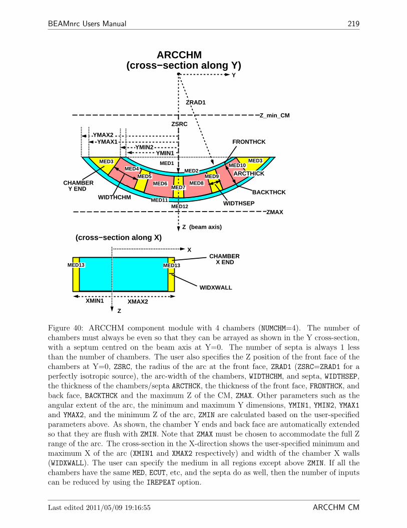
BEAMnrc Users Manual 219
ARCCHM
BACKTHCK
FRONTHCK
ARCTHICK
WIDTHCHMWIDTHSEP
ZSRC
ZRAD1
ZMAX
Z_min_CM
Z (beam axis)
Y
MED1MED3 MED3
MED2MED4
MED5MED6
MED7MED8
MED9
MED10
MED11MED12
(cross−section alon g Y)
(cross−section alon g X)
YMIN1YMIN2
YMAX1YMAX2
Z
X
XMIN1 XMAX2
WIDXWALL
MED13MED13
CHAMBER Y END
CHAMBER X END
Figure 40: ARCCHM component module with 4 chambers (NUMCHM=4). The number ofchambers must always be even so that they can be arrayed as shown in the Y cross-section,with a septum centred on the beam axis at Y=0. The number of septa is always 1 lessthan the number of chambers. The user also specifies the Z position of the front face of thechambers at Y=0, ZSRC, the radius of the arc at the front face, ZRAD1 (ZSRC=ZRAD1 for aperfectly isotropic source), the arc-width of the chambers, WIDTHCHM, and septa, WIDTHSEP,the thickness of the chambers/septa ARCTHCK, the thickness of the front face, FRONTHCK, andback face, BACKTHCK and the maximum Z of the CM, ZMAX. Other parameters such as theangular extent of the arc, the minimum and maximum Y dimensions, YMIN1, YMIN2, YMAX1and YMAX2, and the minimum Z of the arc, ZMIN are calculated based on the user-specifiedparameters above. As shown, the chamber Y ends and back face are automatically extendedso that they are flush with ZMIN. Note that ZMAX must be chosen to accommodate the full Zrange of the arc. The cross-section in the X-direction shows the user-specified minimum andmaximum X of the arc (XMIN1 and XMAX2 respectively) and width of the chamber X walls(WIDXWALL). The user can specify the medium in all regions except above ZMIN. If all thechambers have the same MED, ECUT, etc, and the septa do as well, then the number of inputscan be reduced by using the IREPEAT option.
Last edited 2011/05/09 19:16:55 ARCCHM CM

220 NRCC Report PIRS-0509(A)revL
The input format for ARCCHM and a sample input are given below.
CARDS CM_$ARCCHM******************
-1 Dummy line to indicate start of CM.
0 RMAX_CM(ICM_$ARCCHM) (F10.0): Half-width of outer boundaryof CM (cm) Read in MAIN
1 TITLE_$ARCCHM (60A1): Title of CM.
2 ZSRC_$ARCCHM (F15.0): Distance from front face of chamber at Y=0(ie the lowest point in the arc) to referenceplane in cm.
3 ZRAD1_$ARCCHM (F15.0): Radius of front face of chamber in cm. Fora fully-divergent beam, this may equalZSRC_$ARCCHM.
4 NUMCHM_$ARCCHM (I4): Number of individual ion chambers
5 WIDTHCHM_$ARCCHM (F15.0): Width of each ion chamber in cm.
6 WIDTHSEP_$ARCCHM (F15.0): Width of each septum in cm.
7 ARCTHICK_$ARCCHM (F15.0): Thickness of chambers & septa in cm.
8 FRONTHCK_$ARCCHM (F15.0): Thickness of front face of chamber in cm.
9 BACKTHCK_$ARCCHM (F15.0): Thickness of back face of chamber in cm.
10 WIDXWALL_$ARCCHM (F15.0): Width of chamber wall along x in cm.
11 XMIN1_$ARCCHM,XMAX2_$ARCCHM (2F15.0):
XMIN1_$ARCCHM: Min x dimension outside of x wall (cm).XMAX2_$ARCCHM: Max x dimension outside of x wall (cm).
All YMIN and YMAX are calculated from ZRADs and PHIThe min/max x dimensions inside of the x wall are calculated.ZMIN is calculated from ZRAD, ZSRC, and PHI
12 ZMAX_$ARCCHM (F15.0): The max Z of the CM in cm. Note thatZMAX must be >= ZSRC+ARCTHICK+FRONTHCK+
BACKTHCK
Repeat 13-14 for the following regions:Region 1: region before arc-shaped ion chamber.Region 2: front face of arc-shaped ion chamber.
15 COMPONENT MODULES ARCCHM CM

BEAMnrc Users Manual 221
Region 3: ends of the ion chamber.Region 4 -- 2*NUMCHM+2: chamber or septa
EVEN: chamber ODD: septa Numbering of chambers andsepta goes from -Y to +Y (13-14 only have to berepeated twice for these regions if IREPEAT=1. Seebelow.)
Region 2*NUMCHM+3: back face of arc-shaped ion chamber.Region 2*NUMCHM+4: region surrounding the arc.Region 2*NUMCHM+5: x walls of the chamber
13 ECUT, PCUT, DOSE_ZONE, IREGION_TO_BIT, (IREPEAT) (2F15.0,2I5,(I5)):
ECUT, PCUT: Cutoff energies for electrons and photonsDOSE_ZONE: Dose scoring flag
IREGION_TO_BIT: Bit setting for the regionIREPEAT: Only input for Region 4. Set to 1 to apply this
ECUT, PCUT, IREGION_TO_BIT and MED_IN to allchambers (if DOSE_ZONE > 0, then it will beincremented automatically for each chamber) and thefollowing ECUT, PCUT, DOSE_ZONE, IREGION_TO_BIT andMED_IN to all septa.
14 MED_IN (24A1): Medium of regionused to set MED_INDEX.
Example*******
The following example is an arc-shaped ion chamber containing 10individual chambers. Used for the tomotherapy prototype underdevelopment at the UW.
In this example, ECUT, and PCUT in all regions are set to 0.7 MeVand 0.01 MeV respectively. Note that IREPEAT is set to 1 for thefirst chamber so that ECUT, PCUT, etc only have to be input oncefor all chambers and once for all septa. Also, DOSE_ZONE willbe incremented automatically for the chambers, so that the chamberswill have dose zones 1-10.
************dummy line to indicate new CM***********************60.0, RMAX: outer boundaryTomotherapy ion chamber133.0, ZSRC: distance to front of ARC133.0, ZRAD1: radius of front of arc10, NUMCHM: the number of individual ion chambers1.0, WIDTHCHM: width of each individual ion chamber0.1, WIDTHSEP: width of septa5.0, ARCTHICK: thickness of the arc0.1, FRONTHCK: thickness of front face of chamber
Last edited 2011/05/09 19:16:55 ARCCHM CM

222 NRCC Report PIRS-0509(A)revL
0.2, BACKTHCK: thickness of back face of chamber0.2, WIDXWALL: thickness of x wall-5.0, 5.0, XMIN1, XMAX2: min/max x dimension outside of x wall139.0, ZMAX: Z limit of CM0.700,0.01,0,1, ECUT, PCUT,...,MED of region 1AIR521ICRU0.700,0.01,0,2, ECUT, PCUT,...,MED of front faceAL521ICRU0.700,0.01,0,3, ECUT, PCUT,...,MED of edges of chamberAL521ICRU0.700,0.01,1,1,1, ECUT, PCUT,...,MED of all chambersH2O521ICRU0.700,0.01,0,1, ECUT, PCUT,...,MED of all septaPB521ICRU0.700,0.01,0,2, ECUT, PCUT,...,MED of back faceAL521ICRU0.700,0.01,0,1, ECUT, PCUT,...,MED of region surrounding arcAIR521ICRU0.700,0.01,0,2, ECUT, PCUT,...,MED of x wallsAL521ICRU
15.3.23 SYNCJAWS
SYNCJAWS is a CM similar to DYNJAWS, but which allows synchronization between themotion of the jaws and other dynamic components of the model. In particular, it allows formodeling continuously varying beam configurations by synchronizing source and phantommotions when used in conjunction with sources 20 and 21 in DOSXYZnrc. This CM modulewas contributed by Lobo and Popescu. For the time being, please refer to their originalarticle on these new sources for more details: Phys. Med. Biol. 55, 4431–4443 (2010).
15.3.24 SYNCVMLC
SYNCVMLC is a CM similar to DYNVMLC, but which allows synchronization between themotion of the MLC and other dynamic components of the model. In particular, it allows formodeling continuously varying beam configurations by synchronizing source and phantommotions when used in conjunction with sources 20 and 21 in DOSXYZnrc. This CM modulewas contributed by Lobo and Popescu. For the time being, please refer to their originalarticle on these new sources for more details: Phys. Med. Biol. 55, 4431–4443 (2010).
15.3.25 SYNCMLCE
SYNCMLCE is a CM similar to MLCE, but which allows synchronization between themotion of the MLC and other dynamic components of the model. In particular, it allows formodeling continuously varying beam configurations by synchronizing source and phantommotions when used in conjunction with sources 20 and 21 in DOSXYZnrc. This CM module
15 COMPONENT MODULES SYNCMLCE CM
BEAMnrc Users Manual 223
was contributed by Lobo and Popescu. For the time being, please refer to their originalarticle on these new sources for more details: Phys. Med. Biol. 55, 4431–4443 (2010).
16 Cross-Section Data – PEGS4
Cross-section data for many commonly-used media are included in EGSnrc installation in thefiles 521icru.pegs4dat and 700icru.pegs4dat, both located in the $HEN HOUSE/pegs4/data
directory. The file 521icru.pegs4dat consists of cross-section data from a lower electron en-ergy, AE, of 0.521 MeV to an upper electron energy, UE, of 55 MeV, while 700icru.pegs4datcontains data from AE=0.700 MeV to UE=55 MeV. In both files the lower photon energy,AP, is 0.01 MeV and the upper photon energy, UP, is 55 MeV. These data are based on thedensity effect corrections in ICRU Report 37 [39].
If you wish to determine exactly what the composition of a given material is, it is specifiedon the lines immediately following the MEDIUM label in the .pegsdat file. For an up-to-datelisting of what materials are available in these files, do as follows (only for Linux/Unix):cd $HEN_HOUSE/pegs4/data
grep MEDIUM 700icru.pegs4dat
orgrep MEDIUM 521icru.pegs4dat
To use these data you must specify the names exactly as they appear in the data file beingused.
The NRC EGS user-code examin (found on $HEN HOUSE/user codes/examin) can beused to tabulate or plot the various cross sections for each material.
16.1 Creating additional cross section data
Additional cross section data for BEAMnrc is created by the code PEGS4 (located in$HEN HOUSE/pegs4). A complete description of the PEGS4 code is included in the EGSnrcmanual[1], and users wishing to create their own PEGS4 data are referred to that manual.
Briefly, PEGS4 can be invoked on the command line by typing:
pegs4.exe -i inputfile [-d densityfile]
where inputfile omits the .pegs4inp extention and densityfile omits the .density
extension. The .pegs4inp file specifies whether the the medium is an element (ELEM), com-pound (COMP) or mixture (MIXT); the composition of the medium (by mass, RHOZ, in the caseof MIXT and number of atoms, PZ, in the case of COMP); the density (RHO; whether Rayleighcross-sections are to be included (IRAYL=1); the stopping powers calculated (IUNRST=0 forrestricted stopping powers, IUNRST=1 for unrestricted collision stopping powers, etc.); andwhether ICRU 37 density corrections are to be included (EPSTFL=1). The .pegs4inp filealso specifies the values of AE, AP, UE and UP to use and the name by which the medium willbe referred in all input files using it. There are other input options, but they are beyond thescope of this manual.
Last edited 2011/05/09 19:16:55 Cross-section data-PEGS4

224 NRCC Report PIRS-0509(A)revL
If the user has selected to use ICRU 37 density corrections (EPSTFL=1), then they mustinclude the -d densityfile input when running pegs4. Density correction files are foundin the directory $HEN HOUSE/pegs4/density corrections. It is important to note that ifyou are using a density correction file, the value of RHO specified in the .pegs4inp file mustmatch the material density in the densityfile.density file, which is the third value onthe second line of the file.
The EGSnrc distribution includes some sample input files in the directory $HEN HOUSE/pegs4/input,and it is useful to use these as references if creating your own .pegs4inp file.
When running PEGS4 as described above PEGS4 data is automatically output to either$HEN HOUSE/pegs4/data/inputfile.pegs4dat or $EGS HOME/pegs4/data/inputfile.pegs4dat,depending on what directory it is being run from.
An much easier way to create PEGS4 data is to run PEGS4 from the egs gui (invokedsimply by typing “egs gui”). A screen shot of the PEGS4 option in the egs gui is shownin Figure 41. For more information on egs gui see the EGSnrcMP Manual[2].
Note that egs gui offers an option to append newly-created PEGS4 data to an existing.pegs4dat file.
16 CROSS-SECTION DATA – PEGS4 Cross-section data-PEGS4

BEAMnrc Users Manual 225
Figure 41: Screen shot of the egs gui set to run PEGS4 to create an air data set. Filling inthis form is much easier than creating an input file and access to the density effect correctionsis easy. The GUI does not allow any value except IUNRST = 0. For details, see PIRS-877[2].
16.2 Choice of AE,AP
The parameters AP and AE are the low-energy thresholds for the production of secondarybremsstrahlung photons and knock-on electrons, respectively. The parameters PCUT andECUT are required to be greater than or equal to AP and AE (see sections 10.11 and 10.10).
Selection of AP is simple since one can afford to use a very low value which ensuresaccurate photon transport. We recommend using AP = 0.010 MeV. Note that in practicethis means all bremsstrahlung events are simulated as discrete events.
The choice of AE is more complex since there is some computing time associated withlower values of AE and in some cases, lower values lead to more accurate simulations. Thevalue of AE controls the statistical fluctuations in the energy loss, can affect the electron stepsizes and is a lower limit on ECUT. For a general discussion see, eg. [33, 25].
Although the choice of AE is complex in general, it is fairly easy to give general rules for.In practice, the value of AE has little effect on dose calculations, except in the sense that AEis the lower limit on ECUT. Thus for dose calculations, one should select ECUT as discussed insection 10.10 and then use AE = ECUT. For calculations in which one is looking at electronspectra directly in an electron beam, it is important to use a fairly low value of AE in orderto avoid well known artifacts[33, 25]. Figure 42 gives an example of this artifact for the 9MeV beam from a Clinac2100C. The spectrum calculated with AE=0.521 MeV is clearlymore realistic than that calculated with AE=0.700 MeV. We find that AE = 0.521 MeV isadequate - but note, one can still use ECUT much higher.
Last edited 2011/05/09 19:16:55 Cross-section data-PEGS4
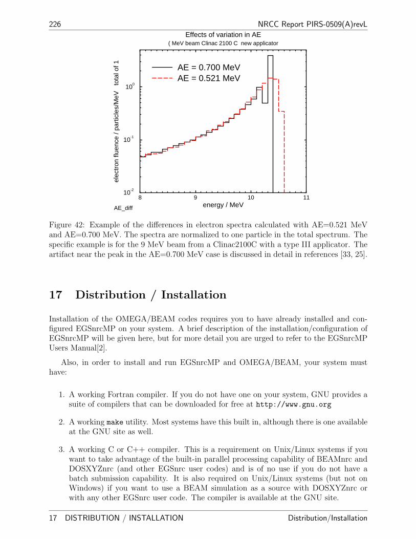
226 NRCC Report PIRS-0509(A)revL
8 9 10 11energy / MeV
10-2
10-1
100
elec
tron
flue
nce
/ par
ticle
s/M
eV
tota
l of 1
Effects of variation in AE( MeV beam Clinac 2100 C new applicator
AE = 0.700 MeVAE = 0.521 MeV
AE_diff
Figure 42: Example of the differences in electron spectra calculated with AE=0.521 MeVand AE=0.700 MeV. The spectra are normalized to one particle in the total spectrum. Thespecific example is for the 9 MeV beam from a Clinac2100C with a type III applicator. Theartifact near the peak in the AE=0.700 MeV case is discussed in detail in references [33, 25].
17 Distribution / Installation
Installation of the OMEGA/BEAM codes requires you to have already installed and con-figured EGSnrcMP on your system. A brief description of the installation/configuration ofEGSnrcMP will be given here, but for more detail you are urged to refer to the EGSnrcMPUsers Manual[2].
Also, in order to install and run EGSnrcMP and OMEGA/BEAM, your system musthave:
1. A working Fortran compiler. If you do not have one on your system, GNU provides asuite of compilers that can be downloaded for free at http://www.gnu.org
2. A working make utility. Most systems have this built in, although there is one availableat the GNU site as well.
3. A working C or C++ compiler. This is a requirement on Unix/Linux systems if youwant to take advantage of the built-in parallel processing capability of BEAMnrc andDOSXYZnrc (and other EGSnrc user codes) and is of no use if you do not have abatch submission capability. It is also required on Unix/Linux systems (but not onWindows) if you want to use a BEAM simulation as a source with DOSXYZnrc orwith any other EGSnrc user code. The compiler is available at the GNU site.
17 DISTRIBUTION / INSTALLATION Distribution/Installation

BEAMnrc Users Manual 227
4. A working C++ compiler. This is required if you want to be able to read/write IAEA-format phase space files.
5. Tcl/Tk. This is necessary for running the BEAMnrc, DOSXYZnrc and BEAMDPGUIs. It can be downloaded from www.activestate.com/Products/ActiveTcl. Seethe GUI User’s Manual[4] for more information. Note that most Linux distributionsalready include Tcl/Tk.
6. A Qt library (version 3.1 or higher). This is necessary for compiling and runningthe GUIs for the EGSnrcMP user codes and is, thus, not strictly necessary for theOMEGA/BEAM codes. You can download the Qt library for free fromhttp://www.trolltech.com. Note that many current Linux distributions include Qt,since the popular Desktop Environment KDE is based on Qt.
7. The xmgrace plotting package which is available athttp://plasma-gate.weizmann.ac.il/Grace. This is distributed with many Linuxdistributions and there is a Windows version.
Note that some of these system requirements are included as part of the EGSnrcMPdistribution (depending upon which method you choose to install EGSnrcMP). More detailsabout this will be given below.
17.1 Installing EGSnrcMP
The EGSnrcMP distribution is available online atwww.irs.inms.nrc.ca/inms/irs/EGSnrc/EGSnrc.html. Download the version appropriatefor your system. There are several different methods for installing the system. The easiestof these is “Method 1”, the self-extracting installation wizard. This includes compressedversions of all codes required for a complete EGSnrcMP distribution which are automaticallyuncompressed at installation time. In the case of Windows, the self extracting download alsoincludes GNU Fortran, C and C++ compilers and the GNU make utility.
“Method 2” for installing EGSnrcMP involves downloading the installation wizard andthe required, compressed codes separately. In addition to the installation wizard itself, therequired downloads to install a complete EGSnrcMP system are:
V4 EGSnrc.egszip The EGSnrcMP system.
V4 spinms.egszip Spin and multiple-scattering data.
V4 user codes.egszip The EGSnrcMP user codes. Not necessary if you are only planningto run the OMEGA/BEAM codes.
V4 manuals.egszip EGSnrcMP documentation.
Additional downloads for Windows are:
Last edited 2011/05/09 19:16:55 Distribution/Installation

228 NRCC Report PIRS-0509(A)revL
V4 MinGW.egszip GNU Fortran, C, C++ compilers and make utility. Only required if youdo not have working versions of these on your system.
V4 winstuff.egszip GUIs for EGSnrcMP user codes and other Windows-specific codes.
For Unix/Linux, if you are planning to use the GUIs for the EGSnrcMP user codes (notnecessary if you are only going to run the OMEGA/BEAM codes), then you should alsodownload the GUI codes, V4 EGSgui.egszip. These downloads and their functions are madeclear on the distribution website. If you have only downloaded a subset of the above .egszipfiles (e.g. the minimum required for eventually installing/running the OMEGA/BEAMcodes) then you should instruct the GUI to only uncompress those archives that you havedownloaded. Rather than physically dowloading the .egszip files yourself, you can alsoinstruct the GUI to automatically download the archives (any subset of them or all of them)from the distribution website before installation. Note that “Method 1” and “Method 2” forEGSnrc installation are not available for the Mac OSX.
The third method, “Method 3”, of installing EGSnrcMP is for Unix/Linux systems andMac OSX systems and uses the installation script install egs. In addition to the script,you must also download the tar files (which may be in compressed format)
V4 EGSnrc.tar[ |.gz|.bz2]
V4 EGSgui.tar[ |.gz|.bz2]
V4 manuals.tar[ |.gz|.bz2]
V4 user codes.tar[ |.gz|.bz2]
V4 spinms.tar[ |.gz|.bz2]
where the base names of the files are the same as for the .egszip files described above. Thesefiles must all be in the same directory before running the install egs script. This method ofinstallation may be necessary if your Linux/Unix system cannot run the installation wizardand is currently the only way of installing EGSnrcMP on Mac OSX. Note that when you usethis method of installation, you must run the script $HEN HOUSE/scripts/finalize egs foruser
at the end (install egs gives you an option to do this automatically) in order to de-fine/create your $EGS HOME area (see next paragraph).
During installation of EGSnrcMP, you will be asked to define the location of $HEN HOUSE,the repository for all EGSnrcMP and OMEGA/BEAM codes (see Figure 2, page 15), andyour $EGS HOME area, where each compiled user code (including accelerators modeled withBEAMnrc) has a subdirectory (see Figure 3). You will also be asked to define the Fortrancompiler that you want to use (defaults are suggested if found on your system). . OnUnix/Linux/Mac OSX systems, if you wish to use functionality that requires a C compilersuch as the built-in parallel processing functionality (see Section 13) or BEAMnrc sharedlibrary sources (see Section 2.3.1), then you must also supply the name of a working C com-piler at this point (default C compilers are suggested if found on your system). On Windowssystems, the parallel processing is unavailable (no batch queuing system) and a precompiledobject file required for BEAM shared library sources is provided during installation, so the
17 DISTRIBUTION / INSTALLATION Distribution/Installation

BEAMnrc Users Manual 229
reason to specify a C compiler here is to make use of the C interfaces which allow EGSnrcuser codes to be written in C (see the EGSnrcMP Manual[49] for more details). You will beasked to give a name to your machine configuration and supply a prefix for the configurationfile, i.e., the .conf file. The name you give for your configuration will determine the namesof the subdirectories off $HEN HOUSE/lib $HEN HOUSE/bin and $EGS HOME/bin. See sec-tion 1.3, page 13, for more information about the directory structure of the $HEN HOUSE andsection 2.12.3, page 31 for more information about the .conf file. We recommend that theprefix of the .conf file be the same as the configuration name to avoid confusion. Finally,you will be given the option to input the name of a working C++ compiler (default C++compilers are suggested if found on your system). This is required to compile the librarynecessary for reading/writing IAEA-format phase space data (see Section 7.3) on all systemsand to allow compilation of the EGSnrc C++ class library, egspp (see the egspp Manual[50]for more details).
Note that, on Unix/Linux/Mac OSX machines, if you supply a working C compilerduring EGSnrcMP installation and the C routines for built-in parallel processing and/orBEAM shared library sources are compiled successfully, then the installation automaticallysets up your config.conf to enable these functions. Similarly, on all systems, if you supplya working C++ compiler during installation and the library of IAEA phase space handlingroutines is compiled successfully, the installation automatically configures config.conf sothat user codes link this library ($HEN HOUSE/iaea phsp/iaea phsp.a) during compilationand can read/write IAEA-format phase space data.
When installing on Windows, you will be given the option to automatically set theenvironment variables HEN HOUSE, EGS HOME and EGS CONFIG (which is set to$HEN HOUSE/specs/config.conf, where config is the prefix you have chosen for the .conf
file). It is recommended that you do this to avoid having to add them manually. Wheninstalling on Unix/Linux/Mac OSX, on the other hand, you do not have the option to setthese variables automatically. Instead, you will be directed to add the statements:
setenv EGS_HOME /full directory path to your EGS_HOME/
(or export EGS_HOME=/full directory path to your EGS_HOME/)
setenv EGS_CONFIG /full_path_to_your_HEN_HOUSE/specs/config.conf
(or export EGS_CONFIG=/full_path_to_your_HEN_HOUSE/specs/config.conf)
source /full_path_to_your_HEN_HOUSE/scripts/egsnrc_cshrc_additions
(or . /full_path_to_your_HEN_HOUSE/scripts/egsnrc_bashrc_additions)
to the .cshrc (or .bashrc) file in your $HOME area. These directions are reiterated in the file$HEN HOUSE/README UNIX. Note that the egsnrc cshrc additions (or egsnrc bashrc additions)script defines $HEN HOUSE. Once you have added these statements, you will then have tosource your .cshrc (or .bashrc) file, or else open a new window, to run EGSnrcMP.
If you are using a batch queuing system (Unix/Linux only) then the file$HEN HOUSE/scripts/batch options.YourSystemName must exist (the distribution includesfiles for at, pbs, keg and nqs but these may require modifications for your system) and youalso must include:setenv EGS BATCH YourSystemName
in your .cshrc file or equivalent in your .bashrc file.
If you wish to use a second compiler or operating system, you can either run the instal-
Last edited 2011/05/09 19:16:55 Distribution/Installation

230 NRCC Report PIRS-0509(A)revL
lation wizard (self-extracting or stand-alone) and select the “Configure existing EGSnrc”option or, if on a Unix/Linux/Mac OSX system, you can run the script$HEN HOUSE/scripts/configure from the $HEN HOUSE/scripts directory. Alternatively,this task can be done from the egs gui interactive GUI for general EGSnrc user codes[51].Note that you must have write permissions on $HEN HOUSE to configure a second com-piler/operating system.
To see the status of your EGSnrcMP installation (especially important if something goeswrong) then:
• If you have used an installation wizard, look in the file$HEN HOUSE/install status/config [unix|win].log.
• If you have used the install egs script, look in the files install.log (in the directorythat you ran install egs from) and config.log (in directory $HEN HOUSE/scripts).
17.2 Installing OMEGA/BEAM
Once EGSnrcMP has been successfully installed, you are now ready to install the OMEGA/BEAMsystem (including BEAMnrc, DOSXYZnrc, BEAMDP, ctcreate, and other utility codes).
The installation can be obtained from the OMEGA/BEAM distribution site at:
www.irs.inms.nrc.ca/inms/irs/BEAM/user manuals/DISTRIBUTION.html
Similar to EGSnrcMP, there are 3 methods for installing the OMEGA/BEAM system:using the self-extracting installation wizard (Linux/Unix and Windows), using the instal-lation wizard with files downloaded separately (Linux/Unix and Windows) and using aninstallation script (Linux/Unix and Mac OSX).
17.2.1 Using the Self-extracting Wizard
The easiest installation method is to use the self-extracting wizard. Download the wiz-ard appropriate for your system and run it by either typing the name of the file (e.g.beam install Linux self.exe) or by double clicking on the file if you are using a Windows-type browser. The self-extracting wizard contains all of the files required to set up a completeOMEGA/BEAM system. When you run the wizard, it will check that you have correctly in-stalled EGSnrcMP by checking for the existence of $HEN HOUSE (both the directory and theenvironment variable), $EGS HOME (directory and environment variable) and $EGS CONFIG
(the config.conf file and the environment variable). If any one of these environmentvariables is not defined or the directory/file indicated by the variable is not present, theninstallation stops with a warning message indicating that you must first correctly installEGSnrcMP. However, if EGSnrcMP was correctly installed, then the wizard goes ahead andinstalls OMEGA/BEAM. OMEGA HOME is automatically defined as $HEN HOUSE/omega andthe directory structure shown in Figure 1(Section 1.3) is created. In addition, the subdirec-tory dosxyznrc is added to the $HEN HOUSE/user codes area (see Figure 2 in section 1.3,page 15).
17 DISTRIBUTION / INSTALLATION Distribution/Installation

BEAMnrc Users Manual 231
Once all directories/files required for the OMEGA/BEAM installation are in place,the wizard will compile the beam build tool (see section 2.2 page 19), BEAMDP[52, 53],ctcreate (see the DOSXYZnrc Users Manual[15], section 15), readphsp (see Section 7.4),statdose (see section 12 of the DOSXYZnrc Users Manual[54]), addphsp (see section 13.4),and dosxyz show[55]. The wizard also determines whether your machine includes a C com-piler and, if it does, it compiles the C routines used for parallel runs with DOSXYZnrc,$HEN HOUSE/user codes/dosxyznrc/read write pardose.c, and puts the object file,read write pardose.o, in the $HEN HOUSE/lib/config directory (where config is thename of your machine configuration defined by the variable EGS CONFIG). The wizard thencreates the file $HEN HOUSE/specs/dosxyznrc config.spec, which is used when compilingDOSXYZnrc to determine whether read write pardose.o will be linked in at compile timeor not. See the DOSXYZnrc Users Manual[15] for more information about read write pardose
and dosxyznrc config.spec. Note that if any of the above compilations fail, the installationdoes not stop, but a warning message is output at the end.
At this point, all of the OMEGA/BEAM codes have been extracted and the utility pro-grams have been compiled on the $OMEGA HOME area. This completes the actual installationof OMEGA/BEAM. The self-extracting wizard then automatically sets up your user’s area(see Figure 3) for OMEGA/BEAM.
To set up your system, the wizard creates the subdirectory chain beamnrc/spec modules
in your $EGS HOME area and copies the example accelerator spec modules (EX10MeVe.module,EX16MVp.module, EXphantom.module, and EXslabs.module) into the spec modules subdi-rectory. The wizard also creates subdirectory dosxyznrc off your $EGS HOME area, copies therequired source code files from$HEN HOUSE/user codes/dosxyznrc into it and compiles DOSXYZnrc. If any of these op-erations fail, the set up does not stop, but a warning message will be output at the end.
The final step of set up is to define your $OMEGA HOME environment variable. If settingup on Windows, then $OMEGA HOME will automatically be set (to/full directory path to $HEN HOUSE/omega). If set up is on Unix/Linux/Mac OSX, $OMEGA HOME
will not automatically be set, but you will be instructed (in the installation wizard displaywindow) to add the statement:
source /full path to your HEN_HOUSE/scripts/beamnrc_cshrc_additions
(or . /full path to your HEN_HOUSE/scripts/beamnrc_bashrc_additions)
to the .cshrc (or .bashrc) file in your $HOME area. Then source .cshrc (or .bashrc).beamnrc cshrc additions (or beamnrc bashrc additions) will define OMEGA HOME and aliasesuseful for running the OMEGA/BEAM codes in Unix/Linux. At this point, configurationof your area is complete.
The installation wizard also gives you the option to put GUI icons (for the BEAMnrc,DOSXYZnrc and BEAMDP GUIs) on the desktop (Windows and Linux KDE only) and/orin the “Start” menu (Windows only).
Instructions, warnings and information appearing in the wizard display window, includingduring configuration, are echoed in the file$HEN HOUSE/install status/config beam [unix|win].log
Last edited 2011/05/09 19:16:55 Distribution/Installation

232 NRCC Report PIRS-0509(A)revL
17.2.2 Using the Installation Wizard with Files Downloaded Separately
You can also install BEAM by downloading the installation wizard and distribution archivesseparately. Once you have downloaded the wizard appropriate for your system, you have theoption of either downloading the .egszip distribution archives,
V4 BEAMnrc.egszip All OMEGA/BEAM codes, GUIs, documentation, and examples (es-sential)
V4 BEAMnrc phsp.egszip The phase space file dosxyznrc test electron medium.egsphsp1
for use with the BEAMDP multiple-source model lab (optional)
V4 BEAMnrc CT.egszip Example CT data in Pinnacle, AAPM, DICOM and CADPLANformats. Pinnacle data is used in the ctcreate lab (optional),
yourself or letting the wizard download the archives directly from the NRC distributionsite. Unlike the self-extracting wizard, this wizard gives you the option to download onlythe essential BEAMnrc system files (V4 BEAMnrc.egszip) and one or none of the optionalarchives, V4 BEAMnrc phsp.egszip and V4 BEAMnrc CT.egszip. This option is useful ifspace is a consideration on your system or if you are not interested in the multiple-sourcemodel and ctcreate labs.
By default, when the GUI is first started, it checks for the existence of all .egszip
archives in the startup directory (i.e. the directory that you are running the installationGUI from). If you have already downloaded all of the files to this directory, then you canproceed with installation immediately. If, however, any files are not found in this directory,then a warning appears. Clicking “OK” in the warning window allows you to proceed withinstallation with:
a. those archives that HAVE been downloaded to to the startup directory (these willautomatically be checked off in the GUI).
b. archives you have downloaded to another directory. In this case, you will have tocheck off the archive files that you have downloaded, ensure that the ‘Local archive(s)”option has been selected, and use the browser at the bottom of the GUI to specify thecomplete path to the directory that you have downloaded the file(s) to. Or
c. archives to be downloaded by the GUI from the distribution site. Check off the archivesyou want to download and select the ‘Download from NRC distribution site” option.
Once you have selected your particular installation method, press the “Next” button toproceed with installation.
This wizard also allows you to choose between doing a “Complete system installation”,which will install the OMEGA/BEAM system and set up your user area, or a “User sys-tem configuration”, which will just set up your user area. The latter option is only used ifOMEGA/BEAM has already been installed (by you, root, or another user) and does notrequire you to download any of the .egszip archives. If you are just setting up the user’s
17 DISTRIBUTION / INSTALLATION Distribution/Installation

BEAMnrc Users Manual 233
area, the wizard checks that both EGSnrcMP and OMEGA/BEAM have already been in-stalled by checking for the existence of $HEN HOUSE (environment variable and directory),$EGS HOME (environment variable and directory), $EGS CONFIG (environment variable and
file) and $HEN HOUSE/omega. If any one of these does not exist, then set up terminates witha warning. Otherwise, configuration will proceed and $HEN HOUSE/omega will become your$OMEGA HOME.
Note that the self-extracting wizard always does the equivalent of a “Complete systeminstallation” with all of the archives.
Installation and set up of your user area proceeds in a manner similar to the self-extracting wizard (see section above) with the exception that only those distribution filesthat you have downloaded are uncompressed. All of the essential codes are contained inV4 BEAMnrc.egszip, so, even if this is the only archive you download, the compilationsdescribed in the previous section will be done.
Similar to the self-extracting wizard, instructions, warnings and information appearingin the wizard display window, including during configuration, are reiterated in the file$HEN HOUSE/install status/config beam [unix|win].log
17.2.3 Using the install beam Script (Unix/Linux only)
If you are using a Linux/Unix system, then you can also install the OMEGA/BEAM systemusing the script install beam. To do this, download the script along with the distribution.tar archives (which can be in compressed format):
V4 BEAMnrc.tar[ |.gz|.bz2]
V4 BEAMnrc phsp.tar[ |.gz|.bz2]
V4 BEAMnrc CT.tar[ |.gz|.bz2]
Descriptions of the archives are the same as for the .egszip archives described above. Again,if space is a consideration, then the only essential archive is V4 BEAMnrc.tar[ |.gz|.bz2].
Run the script by typing install beam in the directory that you downloaded it into. Aswith the installation wizards, the script checks that EGSnrcMP has been installed correctlybefore proceeding. In particular, $HEN HOUSE and $EGS HOME need to be set. You will thenbe prompted to input the full path to the directory where you have stored the distributionarchives. The script then copies the distribution archives into your $HEN HOUSE directory,uncompresses them (if required) and untars them. This sets up the $HEN HOUSE/omega direc-tory tree, which becomes $OMEGA HOME (see Figure 1 page 14), and also sets up the dosxyznrcsubdirectory as part of $HEN HOUSE/user codes (see Figure 2). Once the distribution fileshave been untarred, the .tar archives (which are left behind) are removed from $HEN HOUSE.
Beyond this point, installation proceeds in a manner similar to the wizards. The scriptcompiles the OMEGA/BEAM utility codes beam build, BEAMDP, ctcreate, readphsp,statdose, addphsp and dosxyz show. The script also checks for the existence of a C compileron your machine. If there is one, then it compiles the C routines used by DOSXYZnrc[15]
Last edited 2011/05/09 19:16:55 Distribution/Installation

234 NRCC Report PIRS-0509(A)revL
for parallel calculations, $HEN HOUSE/user codes/dosxyznrc/read write pardose.c andputs the object file, read write pardose.o in $HEN HOUSE/lib/config (where config is thename of your machine as defined during EGSnrcMP installation). Finally, install beam cre-ates the file $HEN HOUSE/specs/dosxyznrc config.spec, which is used when DOSXYZnrcis compiled to determine whether read write pardose.o will be linked in or not. Note thatif any compilations fail, the installation continues, but a warning will be output at the end.
Basic output from the installation appears on the screen and is also echoed in thefile install beam.status, which is written to the directory that install beam was runfrom (Note that this means you MUST have write permission in this directory). Compre-hensive output appears in the file install beam.log, also written to the directory thatinstall beam was run from. The latter file contains the full output from compilations ofthe individual OMEGA/BEAM codes, etc, and is essential for debugging your installationif something goes wrong.
At this point, OMEGA/BEAM is now installed, but in order to run the codes, you mustset up your user area (see Figure 3, page 16). If you are the one installing OMEGA/BEAM,then the install beam script provides you with an option to set up your system automat-ically at the end of the installation. If you choose to do this, then install beam calls thescript $HEN HOUSE/scripts/finalize beam foruser, which performs the set up. If, on theother hand, the OMEGA/BEAM system has already been installed (by you, root, or anotheruser), then you will have to run $HEN HOUSE/scripts/finalize beam foruser separatelyto set up your system.
The finalize beam foruser script goes through the same steps as an installation wizard(see above) to set up your system. First of all, it checks for the existence of $HEN HOUSE (envi-ronment variable and directory), $EGS HOME (environment variable and directory), $EGS CONFIG
(environment variable and file) and $HEN HOUSE/omega (which will become your $OMEGA HOME).If any one of these is not defined, set up terminates with a warning. If everything is defined,the script creates the subdirectory chain beamnrc/spec modules in your $EGS HOME area andcopies the example accelerator modules (EX10MeVe.module, EX16MVp.module, EXphantom.module,and EXslabs.module) into the spec modules subdirectory. Finally, the script creates sub-directory dosxyznrc off of your $EGS HOME area, copies the required source code files from$HEN HOUSE/user codes/dosxyznrc into it and compiles DOSXYZnrc. If any operationsfail, the set up does not stop, but a warning message will be output at the end.
At the end of the set up, you will be instructed to add the statement:
source /full_path_to_your_HEN_HOUSE/scripts/beamnrc_cshrc_additions
(or . /full_path_to_your_HEN_HOUSE/scripts/beamnrc_bashrc_additions)
to the .cshrc (or .bashrc) file in your $HOME area. Then source .cshrc (or .bashrc).beamnrc cshrc additions (or beamnrc bashrc additions) will then define OMEGA HOME
and aliases useful for running the OMEGA/BEAM codes in Unix/Linux.
Detailed output from the finalize beam foruser script (including a reiteration of the in-structions for sourcing the beamnrc cshrc additions or beamnrc bashrc additions script)is found in the file, finalize beam [username].log which will be in the directory$HEN HOUSE/scripts if you have run finalize beam foruser directly from the install beam
script or in the directory that finalize beam foruser was run from on its own.
17 DISTRIBUTION / INSTALLATION Distribution/Installation

BEAMnrc Users Manual 235
Note that script-based installation using the install beam script does not give you theoption to add BEAMnrc, DOSXYZnrc and BEAMDP GUI icons to your desktop.
17.2.4 A Note on Tcl/Tk
Before running the BEAMnrc, DOSXYZnrc and BEAMDP GUIs, you must first have in-stalled Tcl/Tk (this is already installed in most Linux systems) and have included the direc-tory /full path to Tcl installation/bin in your PATH environment variable. For moreinformation on installing Tcl/Tk, see the GUI Manual[4].
18 Known Problems/Restrictions
If RMAX is interior to any other boundaries in the geometry, the results will be in errorsince volumes are not correct and also energy past RMAX is always deposited in region(1),even if still inside another region.
The value for a particle does not take into account the distance to RMAX CM, i.e it isallowed to approach this boundary with large steps. This will lead to inaccuracies in thedose delivered to these regions. For accelerator simulations these errors will be small, but inunusual situations could be significant.
Variables related to the number of particle histories, such as the input variable NCASE,the variable IHSTRY, etc, have been changed to INTEGER*8 to allow for > 2x10⁹ histories.This is particularly useful for restarts and recombining parallel jobs, where a large numberof histories may be accrued. However, some Fortran compilers do not support INTEGER*8.We have compiled with INTEGER*8 successfully on Linux PC, SGI, DEC Alpha, and Sunsparc systems. On our rs6000 system, the compiler gave “length specified is not valid forthe specified type” warnings, reverted to INTEGER*4 and then compiled successfully. Onour HP9000 system, the compiler gave “incompatible type-length combination” errors andcompilation failed. If compilation fails due to INTEGER*8, go into beamnrc.mortran andchange the macro:
REPLACE {$LONG INT} WITH {INTEGER*8}to:
REPLACE {$LONG INT} WITH {INTEGER*4}The code will now compile, but note that you are now limited to 2x10⁹ total histories.
If ICM SPLIT=1, i.e. you want to split particles going into the first CM, and even thoughyou must input NSPLIT PHOT and NSPLIT ELEC, no splitting will occur. To get around thisbug, if you wish to split particles at CM 1, you can insert a dummy CM 1 and then setICM SPLIT=2.
Not all CMs output geometric information of much value for EGS Windows (in particularMESH and ARCCHM).
Last edited 2011/05/09 19:16:55 Distribution/Installation

236 NRCC Report PIRS-0509(A)revL
A restarted run that uses a phase space source with particle recycling will not producedose/uncertainty results identical to a single run with the same total number of histories.This is because the last particle used before the restart may not have been recycled the fullNRCYCL times, and restarting automatically skips to the next particle. Results will agreewithin uncertainty, however.
19 History of Revisions
The files CHANGES_from_BEAMnrc06.for.BEAMnrc07, CHANGES_from_BEAMnrc05.for.BEAMnrc06,CHANGES_from_BEAMnrc03.for.BEAMnrc05, CHANGES_from_BEAMnrc02.for.BEAMnrc03, andsimilar files on $OMEGA_HOME/doc contain a description of all the changes made to the BEAMand BEAMnrc system since the release mentioned. BEAM95 was released at the first coursein Oct, 1995.
19.1 Changes from BEAMnrc08 to BEAMnrc09
Major changes between BEAMnrc08 and BEAMnrc09 are as follows:
• Modified subroutine do rayleigh in beamnrc.mortran so that a new Rayleigh sam-pling scheme can be used with DBS. Modification includes no longer killing thin pho-tons before Rayleigh interactions to avoid spikes in the photon spectra.
• LATCH options now work when DBS is used. They previously did not.
• CM XTUBE was modified to allow the user to have a central region in the outermosttarget slab comprised of a different material. Should allow more accurate modeling ofX-ray tubes.
• Source 24, phase-space source incident from a user-specified angle, added. Conceptand much of the coding of the source is courtesy of Patrick Downes at University ofCardiff, Wales.
• Added source 23, BEAM simulation source from a user-specified angle.
• Fixed bug in CM MLC in which a particle right on a leaf boundary with USTEP∼1×10⁻⁶ resulted in an endless loop.
• Fixed bug in source 8 in DOSXYZnrc (phase-space source incident from multiple di-rections) causing a segmentation fault when many incident angles were specified.
• Fixed bug in BEAMnrc which caused elapsed CPU time stored in the .egsdat file tobe wrong.
• Changed source 19 from a circular gaussian source to an elliptical source defined byseparate gaussian distributions in X and Y.
• Many changes to allow compilation and running in double precision (REAL*8).
19 HISTORY OF REVISIONS Distribution/Installation

BEAMnrc Users Manual 237
• Added a new component module, DYNJAWS, to allow simulation of time-dependentJAW settings. In actuality, this is most likely to be used to simulate dynamic wedges.Similar to DYNVMLC, it can be operated in dynamic (beam on during setting changes)and step-and-shoot (beam off during setting changes) modes.
• Fixed a major bug in MLCQ. The distance to the nearest region boundary was calcu-lated incorrectly in the HOWNEAR subroutine. In at least one observed case, this ledto an error in electron fluence at the bottom of the CM (incident electron beam) andalso caused transport through the CM to be very slow.
19.2 Changes from BEAMnrc07 to BEAMnrc08
Major changes between BEAMnrc07 and BEAMnrc08 are as follows:
• Recoded the opening of .egsinp, .egslog, .egslst and .errors files in BEAMnrc sothat you no longer require libg2c.a when using BEAMnrc as a shared library source.Now, BEAMnrc searches for available Fortran units (i.e. those not already in useby the driving program) to associate with these files. Thus, the confusion of Fortranunits, for which libg2c.a was necessary to resolve, is no longer an issue. This shouldallow BEAMnrc shared libraries to be compiled using gfortran, which had problemswith libg2c.a.
• Introduced dynamic and step-and-shoot modes in the DYNVMLC component module.This allows multiple treatment fields to be simulated in a single run.
• Both BEAMnrc and DOSXYZnrc can now make use of IAEA-format phase space data.In the case of BEAMnrc, IAEA-format data can now be output at scoring planes. Thiswill allow users to use the new IAEA online phase space database. A C++ compileris required for this functionality.
• Added source 10 to DOSXYZnrc. This is source 9 (BEAMnrc shared library source)but from multiple angles in a single simulation.
• “NRC” bremsstrahlung cross-sections, which include electron-electron bremsstrahlungeffects, have been added
• The user now has the option to specify custom Rayleigh form factors for specifiedmedia if simulation of Rayleigh scattering is desired.
• The bremsstrahlung cross section enhancement (BCSE) variance reduction techniquewas introduced. This increases the efficiency of x-ray tube simulations by up to anorder of magnitude and can even increase the efficiency of standard 6 MV acceleratorsimulations by 40%.
• The option to use a rejection plane which can eliminate all fat photons which mightinteract in the air above the phantom has been added as part of DBS.
• A grid scoring option in each scoring plane has been added so that fluence can bescored in a rectangular grid rather than just in circular or square rings.
Last edited 2011/05/09 19:16:55 Distribution/Installation
238 NRCC Report PIRS-0509(A)revL
19.3 Changes from BEAMnrc06 to BEAMnrc07
Major changes between BEAMnrc06 and BEAMnrc07 are as follows:
• Introduced “HOWFARLESS” option for homogeneous phantom calculations in DOSXYZnrc.This option increases efficiency by ∼30% in photon beam sources from acceleratorssimulated using BEAMnrc and by factors of 2.5-3.5 in monenergetic electron beams.
• EXACT is now the default boundary crossing algorithm in BEAMnrc (but not in DOSXYZnrc).This was changed from PRESTA-I after it was shown[12] that the PRESTA-I BCA canresult in dose overprediction by up to 2.5% in a CHAMBER phantom.
• The BEAMnrc and DOSXYZnrc GUI’s now give the user access to various electronimpact ionization theories (only applicable for keV X-Rays) and photon cross-sectiondata other than Storm-Israel (PEGS4).
• The parameter $BDY TOL in $OMEGA HOME/beamnrc/beamnrc user macros.mortran,which defines the “fuzzy boundary” used in the HOWFAR routines of various CMs toensure that particles are actually transported beyond region boundaries was changedfrom 1E-4 cm to 1E-5 cm. The previous value resulted in serious underestimates ofcontaminant electron dose in high-energy photon beams when the JAWS CM was used.
• Introduced a more efficient range rejection scheme that works together with directionalbremsstrahlung splitting (DBS). It can increase the efficiency of DBS by ∼20%.
• Source 19 (circular beam with Gaussian distribution in X-Y) can now have user-specified angular spread.
• Introduced electron splitting for phase space and BEAMnrc simulation sources inDOSXYZnrc. This is used in conjunction with photon splitting (n split) to ensurethat higher-weight contaminant electrons do not compromise statistics.
19.4 Changes from BEAMnrc05 to BEAMnrc06
Apart from many smaller bug fixed and modifications, the major changes between theBEAMnrc05 and BEAMnrc06 distributions can be summarised as follows:
• Added the DYNVMLC CM, designed to simulate the Varian Millenium class of multi-leaf collimators. See the BEAM User’s Manual for more details. Original coding isfrom Emily Heath at McGill University.
• Zdenko Sego at Carleton University has fixed and enabled the the use of multiplesource model as sources in BEAMnrc (ISOURC=31). This option was disabled formany releases.
• Fixed a major bug in the phase space source for DOSXYZnrc. When particles wererecycled, their Z direction cosine (wsrc) was not saved from one use to another, result-ing in particles that either did not hit the geometry or went in non-physical directions.
19 HISTORY OF REVISIONS Distribution/Installation

BEAMnrc Users Manual 239
Simulations either crashed or produced depth-dose curves wildly different from thoseexpected.
• Added many USER macros to the BEAM code which allow a user to easily customize theAUSGAB routine, input parameters, data analysis, global variables, etc. These macrosare changed in beamnrc user macros.mortran
• Custom user inputs can appear between the delimiters :start user inputs: and:stop user inputs: in the BEAMnrc .egsinp file and the GUI will handle them(but not give you access to them).
• Fixed some bugs in the new MLCE CM. Among them: it was possible for particles tobe trapped in “dead air”, not contained within the boundaries of any leaf side-surface,near the bottom of the MLC. Also, leaf overlap restrictions on input were too strict.
• Fixed some bugs in the JAWS CM which resulted in unnecessary warning messagesbeing output. Also, fixed one bug which resulted in occasional particles being discardedwhen transported backwards (W¡0) to the top of the jaws.
19.5 Changes from BEAMnrc03 to BEAMnrc05
Apart from many smaller bug fixed and modifications, the major changes between theBEAMnrc03 and BEAMnrc05 distributions can be summarised as follows:
• Ported the entire set of codes to work with the EGSnrcMP system.
• Electron impact ionization added to the EGSnrc system.
• Added directional bremsstrahlung splitting (DBS) which increases the efficiency forphoton accelerators by more than a factor of 5.
• Included the new CM MLCE which was mostly coded by Nick Reynaert at the Uni-versity of Ghent.
• Added the BEAM shared library source (source 9) to DOSXYZnrc and other EGSnrcuser codes. This required some reorganization of the BEAM code to allow it to be com-piled as a shared library for use as a source in DOSXYZnrc and other user codes. Now,beamnrc.mortran contains subroutines which are called by either beam main.mortran
(regular simulation) or beam lib.mortran (shared library source). Also involved changesto some phase space writing macros in phsp macros.mortran so that, when the BEAMsimulation is used a source, particles are dumped into a source “bin” instead of writtento a phase space file.
• Introduced a new parallel processing approach which optimizes performance on a sys-tem with mixed CPU speeds and utilization factors.
• Updated DICOM CT image reading routine, readCT DICOM.c, used by ctcreate. Theroutine is now independent of libraries from the DICOM CTN (central test node) and iscompatible with the latest DICOM format. Thanks to Nick Reynaert at the Universityof Ghent for sending us the original code.
Last edited 2011/05/09 19:16:55 Distribution/Installation

240 NRCC Report PIRS-0509(A)revL
• Changed uncertainty analysis in BEAMDP so that it uses the history-by-history methodused in all user codes.
• Added an option for source 1 in BEAMnrc (isotropically-radiating point source) to becollimated as a rectangle anywhere on the surface of CM 1. Previously, this could onlybe collimated as a square centred at Z=0.
• Modifications to BEAMnrc, DOSXYZnrc and BEAMDP GUI’s to allow them to runcodes on Windows.
• Fixed a bug in JAWS in which particles that should have been transported rightthrough the tip of the JAWS (since they were within boundary tolerance of the edge)erroneously had their region numbers assigned to the JAW material. This resulted inmany warnings.
• Fixed bugs in CONS3R CM in related to particle region numbers being incorrect whena particle is being transported close to the boundary of the cone.
• Modified the HOWFAR routines in all BEAM CMs so that if a particle is leaving theCM (through the top or bottom) with USTEP=0, then USTEP is given a small positivevalue (1.E−16) to ensure that AUSGAB gets called and the particle gets scored (if thereis a scoring plane at this boundary). This bug was causing significant errors in thephase space file in perverse situations.
19.6 Changes from BEAMnrc02 to BEAMnrc03
• Enabled the RANLUX random number generator in BEAMnrc and DOSXYZnrc. Cannow use either RANLUX or RANMAR.
• Fixed 3 bugs in VARMLC and added the IGNOREGAPS input which increases the ef-ficiency of range rejection for particles deep in the leaves (i.e., far away from theopenings) by ignoring the air gaps between the leaves.
• Fixed a bug in CONS3R which caused particles to be discarded unnecessarily (with awarning) when being transported close to a conical boundary. The region error counterwas not being reset properly with each new initial history.
• Put a restriction that all radii in CONESTAK be ≥ $BDY TOL. Otherwise, a regioncheck fails and the code could enter an endless loop.
19.7 Changes from BEAM00 to BEAMnrc02
• BEAMnrc is based on the EGSnrc system.
• The statistical analysis package in BEAMnrc is based on the history by history tech-nique which greatly reduces the uncertainty on the uncertainties assigned. See thereport on history by history statistics in BEAMnrc and DOSXYZnrc[17] for a com-plete discussion.
19 HISTORY OF REVISIONS Distribution/Installation

BEAMnrc Users Manual 241
• Range rejection within BEAMnrc is based on the EGSnrc calculation of range at eachstep but still does range rejection to ECUT, unlike the default vesion of EGSnrc whichdoes it to AE.
• Added sources 7 and 8 to DOSXYZnrc. Source 7 is a parallel rectangular beam incidentfrom multiple, user-selected angles. Source 8 is a phase space source incident frommultiple, user-selected angles. This allows modelling of arc therapy.
• Added an option to DOSXYZnrc which allows the the user to output a .egsphant filefrom non-CT data. This allows you to display isodose contours using dosxyz show innon-CT phantoms.
• Added a feature to the GUI for the JAWS CM which allows the X and Y positionsof the JAWS to be set to give an arbitrary rectangular field size at a given SSD bydiverging from an arbitrary focal point on the axis. Note that this is useful only forthe photon jaw field size, not the electron field size (for which the jaws are typicallyset at a larger size).
• Upgraded VARMLC so that it can now simulate two different classes of multi-leafcollimators: those in which the tongue and groove do not extend beyond the top andbottom of the leaves (the original class which VARMLC was designed to simulate);and those in which the tongue and groove extend to either the top or bottom of theleaves (the new class).
• Corrected some serious bugs in VARMLC. Among them, the distance along the particletrajectory to the nearest vertical boundary parallel to the leaf opening direction was notcalculated correctly. This was because some cases were omitted in $VARMLC HOWFAR.
• Changed all variables that store summed quantities in BEAMDP from REAL*4 toREAL*8. This overcomes a potential problem when quantities from a large (> 1 mil-lion) number of particles are being summed. Previously, it was possible for summedquantities to become so large that they consumed all decimal places in REAL*4 vari-ables, and any further contributions from individual particles (especially those withlow weight) were not included in the sum.
• Fixed a bug in the JAWS CM in which particles were not transported into the jawmaterial from the air in front of the jaws with a $BDY TOL overshoot. This resultedin endless loops and WARNING messages when the transport into the jaws was near thejaw tips.
• Fixed a fairly major bug in DOSXYZnrc in which the ISMOOTH and NRCYCL optionsfor phase space sources could not be used at the same time or else they caused er-rors. Previously, incident particle positions and direction cosines were recycled in theDOSXYZnrc phantom coordinate system. When smoothing was also turned on, thenthese particles were also redistributed in the phantom coordinate system. This wasan error, since redistribution is only meaningful in the coordinate system of the phasespace source. We solved the problem by taking care of particle recycling and redistribu-tion before rotating the source into its position in the DOSXYZnrc phantom coordinatesystem.
Last edited 2011/05/09 19:16:55 Distribution/Installation
242 NRCC Report PIRS-0509(A)revL
• Fixed a bug in BEAM in which particles were scored at a scoring plane even thoughthey were scattered back into the CM before actually crossing the scoring plane.
• Fixed a bug in CONS3R CM. Previously, particles with a mismatch between regionnumber and radial position were transported MIN(USTEP,1.0E-5) and their regionnumber was automatically changed. This caused problems for particles that werecrossing a radial boundary but ended up just short of it (due to roundoff error). In thiscase the region number was reset to where the particle was coming from even though,clearly, the MIN(USTEP,1.0E-5) step took it into the new region. We now check theradial position of the particle after the MIN(USTEP,1.0E-5) step before changing theregion number.
20 Acknowledgements
The original BEAM code was developed as part of a major collaboration with Rock Mackie’sgroup at the University of Wisconsin under a grant from the National Institutes of Health(R01-CA52692). At NRC there have been a wide variety of people who supported theproject directly or indirectly. Michel Proulx has been our able computer system manager;Alex Bielajew was involved at early stages and helped maintain the NRC EGS4 system;Jiangshen Sun did a variety of quality assurance checks on the input/output routines forthe CMs. Two Research Associates played major roles in the development of the BEAMsystem, Bruce Faddegon was deeply involved with the initial design of the software systemthat evolved into BEAM and Charlie Ma was a major developer of many parts of the codesystem. The following graduate students made major contributions to many aspects of thecoding and overall development of the code: George Ding, Jiansu Wei, Geoff Zhang andDaryoush Sheikh-Bagheri. Most of the students and RAs have at times been authors ofearlier versions of this manual and their contributions to the manual remain in many places.
Elsayed Ali of Carleton University developed the BCSE variance reduction coding anddrafted section 6.4 of the manual which describes this technique.
The OMEGA/BEAM installation wizard was created by Ernesto Mainegra-Hing at theNRC.
The CM ARCCHM was contributed by Marv Glass of University of Wisconsin.
The first version of the CM MLCQ was contributed by by Hugo Palmans and Kristiaan DeVlamynck of the University of Gent, Belgium.
The first version of the VARMLC CM was written by Ajay Kapur with Charlie Ma atStanford University.
The CM called MLCE was mostly coded by Nick Reynaert at the University of Ghent.
We have had many users point out and sometimes correct bugs. In particular we wishto recognise John Antolak and those he worked with at MDACC in Houston for their many
20 ACKNOWLEDGEMENTS Distribution/Installation

BEAMnrc Users Manual 243
clear bug reports, the first version of source 19 and especially the current version of theBLOCK CM.
The source code and bug reports explicitly mention the contributions of many others.
21 References
[1] I. Kawrakow and D. W. O. Rogers. The EGSnrc Code System: Monte Carlo simulationof electron and photon transport. Technical Report PIRS–701 (4th printing), NationalResearch Council of Canada, Ottawa, Canada, 2003.
[2] I. Kawrakow, E. Mainegra-Hing, and D. W. O. Rogers. EGSnrcMP: the multi-platformenvironment for EGSnrc. Technical Report PIRS–877, National Research Council ofCanada, Ottawa, Canada, 2003.
[3] D. W. O. Rogers, B. A. Faddegon, G. X. Ding, C.-M. Ma, J. Wei, and T. R. Mackie.BEAM: A Monte Carlo code to simulate radiotherapy treatment units. Med. Phys.,22:503 – 524, 1995.
[4] J. A. Treurniet, B. R. B. Walters, and D. W. O. Rogers. BEAMnrc, DOSXYZnrc andBEAMDP GUI User’s Manual. NRC Report PIRS 0623(rev C), 2004.
[5] I. Kawrakow. Accurate condensed history Monte Carlo simulation of electron transport.I. EGSnrc, the new EGS4 version. Med. Phys., 27:485 – 498, 2000.
[6] D. W. O. Rogers, I. Kawrakow, J. P. Seuntjens, and B. R. B. Walters. NRC UserCodes for EGSnrc. Technical Report PIRS–702, National Research Council of Canada,Ottawa, Canada, 2000.
[7] D. W. O. Rogers, C.-M. Ma, G. X. Ding, and B. Walters. BEAM Users Manual. NRCReport PIRS 509a, 1995.
[8] D. W. O. Rogers, C.-M. Ma, G. X. Ding, and B. Walters. BEAM Users Manual. NRCReport PIRS 509(a)revB, 1997.
[9] D. W. O. Rogers, C.-M. Ma, G. X. Ding, B. Walters, D. Sheikh-Bagheri, and G. G.Zhang. BEAM98 Users Manual. NRC Report PIRS 509(a)revC, 1998.
[10] D. W. O. Rogers, C.-M. Ma, G. X. Ding, B. Walters, D. Sheikh-Bagheri, and G. G.Zhang. BEAMnrc Users Manual. NRC Report PIRS 509(a)revF, 2001.
[11] D. W. O. Rogers, B. Walters, and I. Kawrakow. BEAMnrc Users Manual. NRC ReportPIRS 509(a)revH, 2004.
[12] B. R. B. Walters and I. Kawrakow. Technical note: Overprediction of dose with defaultPRESTA-I boundary crossing in DOSXYZnrc and BEAMnrc. Med. Phys., 34:647 – 650,2007.
[13] C.-M. Ma, P. Reckwerdt, M. Holmes, D. W. O. Rogers, and B. Geiser. DOSXYZ UsersManual. NRC Report PIRS 509b, 1995.
Last edited 2011/05/09 19:16:55 References

244 NRCC Report PIRS-0509(A)revL
[14] Blake Walters and D. W. O. Rogers. QA for the BEAM System; Component Modules,Variance Reduction Options and Source Routines. NRC Report PIRS–509k, 1995.
[15] B. R. B. Walters, I. Kawrakow, and D. W. O. Rogers. DOSXYZnrc Users Manual. NRCReport PIRS 794 (rev B), 2005.
[16] J. A. Treurniet and D. W. O. Rogers. EGS Windows4.0 User’s Manual. NRC ReportPIRS–0669, 1999.
[17] B. R. B. Walters, I. Kawrakow, and D. W. O. Rogers. History by history statisticalestimators in the BEAM code system. Med. Phys., 29:2745 – 2752, 2002.
[18] Iwan Kawrakow, D. W. O Rogers, and B.R.B. Walters. Large efficiency improvementsin BEAMnrc using directional bremsstrahlung splitting. Med. Phys., 31:2883 – 2898,2004.
[19] D. W. O. Rogers, I. Kawrakow, J. P. Seuntjens, B. R. B. Walters, and E. Mainegra-Hing.NRC User Codes for EGSnrc. Technical Report PIRS–702(RevB), National ResearchCouncil of Canada, Ottawa, Canada, 2003.
[20] J. A. Treurniet and D. W. O. Rogers. BEAM, DOSXYZ and BEAMDP GUI User’sManual. NRC Report PIRS 0623(rev A), 1999.
[21] Daryoush Sheikh-Bagheri and D. W. O. Rogers. BEAM Example: A 16 MV photonbeam. NRC Report PIRS–509i, 1995.
[22] G. G. Zhang and D. W. O. Rogers. BEAM Example: A 10 MeV electron beam. NRCReport PIRS 509h, 1995.
[23] Blake Walters and D. W. O. Rogers. BEAM Example: Depth-Dose in a Phantom.NRC Report PIRS–509j, 1995.
[24] A. F. Bielajew, R. Mohan, and C. S. Chui. Improved bremsstrahlung photon angularsampling in the EGS4 code system. National Research Council of Canada Report PIRS-0203, 1989.
[25] D. W. O. Rogers and A. F. Bielajew. Monte Carlo techniques of electron and photontransport for radiation dosimetry. In K. R. Kase, B. E. Bjarngard, and F. H. Attix,editors, The Dosimetry of Ionizing Radiation,Vol III, pages 427 – 539. Academic Press,1990.
[26] E. S. M. Ali and D. W. O. Rogers. Efficiency improvements of x-ray simulations inEGSnrc user-codes using Bremsstrahlung Cross Section Enhancement (BCSE). Med.Phys., 34:2143 – 2154, 2007.
[27] E. Mainegra-Hing and I. Kawrakow. Efficient x-ray tube simulations. Med. Phys.,33:2683 – 2690, 2006.
[28] R. Capote, R. Jeraj, C.-M. Ma, D.W.O. Rogers, F. Sanchez-Doblado, J. Sempau, J. Se-untjens, and J.V. Siebers. Phase-Space Database for External Beam Radiotherapy.IAEA Report INDC(NDS)-0484, 2005.
[29] M. Luscher. A portable high-quality random number generator for lattice field theorysimulations. Computer Phys. Commun., 79:100 – 110, 1994.
[30] F. James. RANLUX: A Fortran implementation of the high-quality pseudorandomnumber generator of Luscher. Computer Phys. Commun., 79:111 – 114, 1994.
References

BEAMnrc Users Manual 245
[31] G. Marsaglia and A. Zaman. A new class of random number generators. Annals ofApplied Probability, 1:462 – 480, 1991.
[32] G. Marsaglia, A. Zaman, and W. W. Tsang. Toward a universal random numbergenerator. Statistics and Probability Letters, 8:35 – 39, 1990.
[33] D. W. O. Rogers. Low energy electron transport with EGS. Nucl. Inst. Meth., 227:535– 548, 1984.
[34] B. J. Foote and V. G. Smyth. The modelling of electron multiple-scattering inEGS4/PRESTA and its effect on ionization-chamber response. Nucl. Inst. Meth.,B100:22 – 30, 1995.
[35] A. F. Bielajew and D. W. O. Rogers. PRESTA: The Parameter Reduced Electron-Step Transport Algorithm for electron Monte Carlo transport. Nuclear Instruments andMethods, B18:165 – 181, 1987.
[36] H. W. Koch and J. W. Motz. Bremsstrahlung cross-section formulas and related data.Rev. Mod. Phys., 31:920 – 955, 1959.
[37] S. M. Seltzer and M. J. Berger. Bremsstrahlung spectra from electron interactions withscreened atomic nuclei and orbital electrons. Nucl. Inst. Meth. Phys. Res. B 12, 12:95– 134, 1985.
[38] S. M. Seltzer and M. J. Berger. Bremsstrahlung energy spectra from electrons withkinetic energy from 1 kev to 10 gev incident on screened nuclei and and orbital electronsof neutral atoms with z = 1-100. Atomic Data and Nuclear Data Tables, 35:345–418,1986.
[39] ICRU. Stopping powers for electrons and positrons. ICRU Report 37, ICRU, Washing-ton D.C., 1984.
[40] O. Klein and Y. Nishina. Uber die Streuung von Strahlung durch freie Elektronen nachder neuen relativistischen Quantendynamik von Dirac. Z. fur Physik, 52:853–868, 1929.
[41] R. Ribberfors. . Phys. Rev. B, 12:2067, 1975.
[42] J. W. Motz, H. A. Olsen, and H. W. Koch. Pair production by photons. Rev. Mod.Phys., 41:581 – 639, 1969.
[43] F. Sauter. Uber den atomaren Photoeffekt in der K-Schale nach der relativistischenWellenmechanik Diracs. Ann. Physik, 11:454 – 488, 1931.
[44] E. Storm and H. I. Israel. Photon cross sections from 1 keV to 100 MeV for elementsZ=1 to Z=100. Atomic Data and Nuclear Data Tables, 7:565 – 681, 1970.
[45] J. H. Hubbell and I. Øverbø. Relativistic atomic form factors and photon coherentscattering cross sections. J. Phys. Chem. Ref. Data, 9:69, 1979.
[46] I Kawrakow. Electron impact ionization cross sections for egsnrc. Med. Phys. (abstract),29:1230, 2002.
[47] D. E. Cullen, S. T. Perkins, and J. A. Rathkopf. The 1989 Livermore EvaluatedPhoton Data Library (EPDL). Lawrence Livermore National Laboratory Report UCRL-ID-103424 (Livermore, Calif), 1990.
[48] M. J. Berger and J. H. Hubbell. XCOM: Photon Cross Sections on a Personal Computer.Report NBSIR87–3597, NIST, Gaithersburg, MD20899, 1987.
Last edited 2011/05/09 19:16:55 References

246 NRCC Report PIRS-0509(A)revL
[49] Iwan Kawrakow, Ernesto Mainegra-Hing, and D.W.O. Rogers. EGSnrcMP, the newmulti platform version of EGSnrc. Med. Phys. (abstract), 31:1731, 2004.
[50] I. Kawrakow. egspp: the EGSnrc C++ class library. Technical Report PIRS–899,National Research Council of Canada, Ottawa, Canada, 2005.
[51] E. Mainegra-Hing. User Manual for egs inprz, a GUI for the NRC RZ user-codes.Technical Report PIRS–801(RevA), National Research Council of Canada, Ottawa,Canada, 2003.
[52] C.-M. Ma and D. W. O. Rogers. BEAMDP Users Manual. NRC Report PIRS 509c(revA), 2004.
[53] C.-M. Ma and D. W. O. Rogers. BEAMDP as a General-Purpose Utility. NRC ReportPIRS 509e(rev A), 2004.
[54] B. R. B. Walters and D. W. O. Rogers. DOSXYZnrc Users Manual. NRC Report PIRS794 (rev B), 2004.
[55] I. Kawrakow. The dose visualization tool dosxyz show. NRC Report PIRS 0624, 1998.
References

BEAMnrc Users Manual 247
Last edited 2011/05/09 19:16:55 References

248 NRCC Report PIRS-0509(A)revL
Appendix A:
Specifications for Component Modulesfor BEAMnrc
D. W. O. Rogers, G.X. Ding, C.M. Ma and B.A. FaddegonIonizing Radiation Standards
National Research Council of Canada Ottawa
Printed: May 18, 2011Last Edited: 2001-02-07 14:30:56-05
Abstract
This report is for BEAMnrc code developers and is not needed for those who just want touse the code. The report specifies what each component module must do, how it must doit, the tools available and the documentation to be followed. There is a separate reportdescribing the QA to be done on a CM if it is modified[14]. It is assumed that the reader isan experienced EGSnrc user.
Appendix A: Specs for CMs for BEAMnrc

BEAMnrc Users Manual 249
A.1 Overview
BEAMnrc is a general purpose code for doing Monte Carlo simulations of radiotherapybeams. One of its design features is that each part of the accelerator or source unit isconsidered to be a single component module which takes up an horizontal slab portion of theaccelerator. These component modules are re-usable and are completely independent. Theymust communicate with the rest of the system in certain well specified ways. The purposeof this document is to list all the specifications of such a component module includingthe documentation required for such a component module. The quality assurance requiredfor each component module is described in an associated report by Walters and Rogers(QA for the BEAM System: Component Modules, Variance Reduction Options and SourceRoutines).
Two MORTRAN source files make up each component module. The MORTRAN macros specificto component module CMNAME are contained in CMNAME_macros.mortran. These macrosare used by BEAMnrc proper and/or the EGS subroutines and/or the component modulesubroutines. The set of subroutines specific to component module CMNAME are contained inCMNAME_cm.mortran.
When you build an accelerator, beam build ensures that within each CM the string$CMNAME is replaced by a user-supplied identifier everywhere it appears in the CMs mor-tran source code. The subroutine and macro names, COMMON name, and variable namesspecific to a given component module all either begin or end with $CMNAME. Every compo-nent module must have an unambiguous identifier. This prevents duplication of any of thesenames when multiple component modules are used in a simulation. Using this convention,the same component module may appear many times in a BEAMnrc code.
CMNAME_macros.mortran
The file CMNAME_macros.mortran contains at least two MORTRAN replacement macros usedby the component module subroutines. The macro COMIN/CM_$CMNAME/ is the COMMON blockreplacement macro for component module CMNAME. The $CMNAME_CM_HOWNEAR macro is re-quired by MORTRAN SUBROUTINE ELECTR when the HOWNEAR replacement macro of BEAMnrcproper is used. This macro calculates the distance from the current location of the particle tothe nearest boundary in the component module with identifier CMNAME. The macro is also usu-ally used in subroutine HOWFAR_$CMNAME as well. Note that in most of the existing CMs, the$CMNAME_CM_HOWNEAR macro is just a call to a HOWNEAR $CMNAME subroutine. The subroutineis located in the file $CMNAME cm.mortran and performs the actual calculation of perpendicu-lar distance to the nearest boundary. The use of a subroutine HOWNEAR $CMNAME (with a callto it from the $CMNAME_CM_HOWNEAR macro) is recommended in EGSnrc because variablesassociated only with the calculation of HOWNEAR need only be declared inside the subroutine.Otherwise, these variables must be appended to the $DEFINE-LOCAL-VARIABLES-ELECTR
macro in EGSnrc.
CMNAME_cm.mortran
The CMNAME_cm.mortran file contains the following subroutines written for each componentmodule:
• HOWFAR_$CMNAME – a standard EGSnrc SUBROUTINE HOWFAR for a component mod-ule CMNAME. It is used during the simulation for defining the geometry via boundary
Last edited 2011/05/09 19:16:55 Appendix A: Specs for CMs for BEAMnrc

250 NRCC Report PIRS-0509(A)revL
checking and setting region-dependent parameters.
• HOWNEAR $CMNAME – a subroutine for component module $CMNAME which calculates theperpendicular distance to the nearest boundary (ie not along the particle trajectory).This is called from the macro $CMNAME CM HOWNEAR. See above for a more detaileddescription of the relationship between the HOWNEAR subroutine and the HOWNEAR macro.
• WHERE_AM_I_$CMNAME – used to determine region of particle upon entry into componentmodule CMNAME.
• INPUT_$CMNAME – prompts for and digests input from the interactive user or theparameter-definition file (i.e. file.egsinp) for information related to componentmodule CMNAME.
• ISUMRY_$CMNAME – writes summary of input for component module CMNAME to listing.
A.2 Writing Component Modules
Source for all CMs must be written in MORTRAN3. See the EGS4 manual, SLAC265, for aspecification of MORTRAN3.
Component module names are capitalized, from 1 to 8 characters long, and are unam-biguous, for example, the component module SLABS is already in use and new componentmodules must not have this name. When writing component modules it is useful to adhereto the following established convention for code formats:
• MORTRAN3 replacement macros specific to the component module are placed inCMNAME_macros.mortran where CMNAME is the name of the component module.
• Indent 3 spaces for all MORTRAN3 LOOPS, and FORTRAN DO and IF statements.
• Capitalize all MORTRAN3 (this is essential) and FORTRAN code.
• Format for replacement macros should be as follows to allow the CMtoc utility to beused: REPLACE {text} WITH {<CR>
• Incorporate extensive documentation at the start of each component module subroutinefile, following the conventions established in SLABS_cm.mortran.
A.2.1 Tips
• To prepare for writing a new component module or modifying an existing one, read thein-line documentation at the beginning of beamnrc.mortran, beamnrc_user_macros.mortran,and beamnrc_cm_macros.hdr. Next read all of SLABS_cm.mortran andSLABS_macros.mortran. Also look at the variables in COMMON/CMs/, which are ofgeneral use in writing component modules.
Appendix A: Specs for CMs for BEAMnrc

BEAMnrc Users Manual 251
• Write SUBROUTINE HOWFAR_$CMNAME in CMNAME_cm.mortran first, writing theCOMIN/CM_$CMNAME macro, which defines all the variables needed, at the same time.The outer boundary of the component module is checked in the HOWFAR subroutine inBEAMnrc proper, and need not be checked here.
• Next write the SUBROUTINE HOWNEAR_$CMNAME for component module CMNAME
in CMNAME_cm.mortran. This macro returns the nearest distance to any boundary fromthe current particle position (DNEAR ). Then, write a macro in $CMNAME macros.mortran
called $CMNAME CM HOWNEAR which is just a call to subroutine HOWNEAR $CMNAME. If yourgeometry is too complex to calculate the nearest perpendicular distance to a boundary,then just write the line:REPLACE {$CMNAME CM HOWNEAR(#)} WITH { {P1}=0; }in the $CMNAME macros.mortran file, and omit the subroutine HOWNEAR $CMNAME fromCMNAME_cm.mortran.
• Write the rest of the component module subroutines for CMNAME in the order:WHERE_AM_I_$CMNAME, SUBROUTINE INPUT_$CMNAME followed by ISUMRY_$CMNAME.
• Use the macro and subroutine files from an established component module such asSLABS or CONESTAK as a template for the new component module. Much of the codecan be used for the new component module with only minor modifications. Thisdoes not generally apply to the SUBROUTINE HOWFAR_$CMNAME, the most difficult ofthe component module subroutines to write.
• When the coding is completed, follow established quality assurance procedures closely.The procedures contained in the QA document listed at the beginning of this reportare the minimum.
• Your code will be read and modified by others, so ensure that it is clearly laid out,extensively documented, and conforms closely to the established conventions.
A.3 Specifications–CMNAME macros.mortran
For every component module, this file must be created. It contains at least the two macrosspecific to the particular CM specified below, but the user may write as many as convenient.
Naming conventions in CMNAME_macros.mortran:
• Use $CMNAME throughout (eg.$SLABS) except in those cases (usually output) where youwant the original CM name to be used, usually to identify the type of CM for outputpurposes.
• The component module name ($CMNAME) appears at the start of all MORTRAN3 macronames (eg.$SLABS_CM_HOWNEAR).
• The component module name ($CMNAME) appends all local variable names (eg.ICM_$SLABS).
Last edited 2011/05/09 19:16:55 Appendix A: Specs for CMs for BEAMnrc

252 NRCC Report PIRS-0509(A)revL
A.3.1 COMIN/CM $CMNAME macro
This macro defines the COMIN which contains the values associated with this specific CM anda few links to the rest of the simulation. Nothing is mandatory since only the writer of agiven CM ever uses these variables. Typically we find it useful to define at least the followingvariables:
• ICM_$CMNAME: an index specifying which CM this is, starting from 1 nearest the source.It is usually set inSUBROUTINE INPUT_$CMNAME.
• IR $CMNAME: the local region number within the CM. This is often used in the HOWFAR
and HOWNEAR subroutines.
• IRSTART_$CMNAME: first absolute region number for this CM. It is usually set inSUBROUTINE INPUT_$CMNAME and equals IR_start_CM(ICM) from COMIN/CMs.
• IREND_$CMNAME: last absolute region number for this CM. It is usually set inSUBROUTINE INPUT_$CMNAME and equals IR_start_CM(ICM+1)-1 from COMIN/CMs.
• TITLE_$CMNAME: title(60) (character*1). It is usually set inSUBROUTINE INPUT_$CMNAME.
• N_GAP_$CMNAME: flag, = 0 if no air gap this CM, = 1 if air gap at top of CM. It is usuallyset in SUBROUTINE INPUT_$CMNAME.
As well, all geometric parameters associated with this CM are defined in this COMIN andfilled in SUBROUTINE INPUT_$CMNAME usually. These MUST have the string _$CMNAME ap-pended at the end of their name to ensure unique names if COMINs are defined more thanonce.
A.3.2 $CMNAME CM HOWNEAR(#) macro
This macro is usually just a call to SUBROUTINE HOWNEAR $CMNAME (See Section A.4.5 below),which returns the perpendicular distance from the particle to the nearest boundary. However,this macro is the only means by which the HOWNEAR subroutine is called and is used in EGSnrcand sometimes in the SUBROUTINE HOWFAR_$CMNAME.
A.4 Specifications–CMNAME cm.mortran
Naming conventions in CMNAME_cm.mortran:
• Use $CMNAME throughout, that is, the name of the component module should not bedirectly written into the code. This permits a change of identifier simply by changingthe .module file.
• $CMNAME appends all subroutine names.
Appendix A: Specs for CMs for BEAMnrc

BEAMnrc Users Manual 253
• $CMNAME appears at the start of all MORTRAN macro names.
• $CMNAME appends all local variable names.
General RequirementsAt the top of the source a set of comments on records starting with "I> must define thegeometry accurately and the inputs required from unit 5. Use of the "I> comment ensuresthat we will be able to pick up the description of the input for the next edition of the usersmanual (i.e.this is the primary documentation for input - make it clear).
A.4.1 SUBROUTINE INPUT $CMNAME
On being called, the following information is available to the routine (all via COMIN/CMs
except NMED which is in COMIN/GEOM):
• ICM: the number of this CM, starting from 1 for smallest z.
• IR_start_CM(ICM): the absolute region number this CM starts at. It is set by previousCM’s input routine and for the ICM=1 case it is set in main (to 2 since region 1 is theexterior).
• RMAX_CM(ICM): outer boundary of this CM, read in by main for each CM. It is either theradius or 1/2 the side for a square boundary.
• NMED: The number of media already asked for in any given simulation.
• MEDIA(24,I),I=1,NMED: names of media already asked for.
The following variables from COMIN/CMs must all be set, not necessarily from user input(i.e. the code may define them for the user).
• RMAX_CM_FLAG(ICM), flag for each CM which specifies what quantity RMAX_CM is forthis CM (RMAX_CM is set by MAIN). If flag = 0, not used; flag = 1, it is radius of outerboundary of CM; flag = 2, it is distance to edge of square outer boundary of CM (1/2 ofside). It is used in main SUBROUTINE HOWFAR to check the outer boundaries, after theindividual HOWFAR_$CMNAME routine has done its work. One should avoid redundantcalculations.
• IERR_GEOM(ICM), flag which must be initialized to zero and set non-zero to flag inputproblem. Set < 100, it specifies number of errors detected within CM, >100 specifiesthat the CM overlaps the one above it. MAIN routine will exit before transport, butinput is continued and checked.
• Z_min_thick(ICM,j) and MED_min_thick(ICM,j): minimum thickness in cm andmedium number of up to j = 5 regions in ICM for an electron going through CM #ICM. It is used for range rejection. It is set in each CM input routine. Region with j=1is closest to the bottom plane. Often only one is needed or possible and this is givenby the total thickness of the CM and medium is air (i.e. MEDIUM 1).
Last edited 2011/05/09 19:16:55 Appendix A: Specs for CMs for BEAMnrc

254 NRCC Report PIRS-0509(A)revL
• Z_min_CM(ICM+1) for next CM is set as the back of this CM.
• Z_gap_THICK(ICM),thickness of air gap at front of CM, if it exists. IfZ_gap_THICK(ICM)= 0, then there is no air gap at the front of this CM.
• IR_start_CM(ICM+1): first absolute region for next CM, set once the number of regionsin the current CM is known.
We find it useful to set the variables in COMIN/CM_$CMNAME listed in section A.3.1.
All variables required by the geometry for this CM (with _$CMNAME at the end of the name)must be input and stored in COMIN/CM_$CMNAME.
The following EGSnrc variables must be set:
• ECUT(IRA) & PCUT(IRA) for all regions IRA in the CM (including the air gap). If notset, the defaults are AE and AP for the medium in each region.
• MED(IRA) the medium index for every region must be set
• MEDIA(24,I) must be loaded for new MEDIA that are asked for. Note the macro$MED_INPUT($CMNAME) handles this automatically. This macro requires NMED to con-tain the current number of different media that have already been read in and storedin MEDIA.
• RHOR(IRA) the density in each region in g/cm3. It need only be set by the user if it isdifferent from the value included in the PEGS4 data set. After the call to HATCH, it willinclude this latter value if left 0.0 prior to the HATCH call.
The following variables in COMIN/SCORE must be set.
• DOSE_ZONE(IRA) = 0 if no dose scored, otherwise =dose zone that dose from this regionscored in. Note that one dose zone can include the dose deposited in many geometricregions.
• NDOSE_ZONE, largest dose scoring zone number assigned so far.
• IREGION_to_BIT(IRA): mapping from absolute regions to LATCH bits (i.e. which bit invariable LATCH is this region associated with).
• MAX_BIT: current largest bit being set.
The following variable in COMIN/GEOM must be set: NREG: total number of regions in thegeometry model up to and including this CM (in COMIN/GEOM). It should equalIR_start_CM(ICM+1)-1.
Appendix A: Specs for CMs for BEAMnrc

BEAMnrc Users Manual 255
A.4.2 SUBROUTINE ISUMRY $CMNAME
This routine, which is called after HATCH, must summarize all data related to the use of thisCM in any given run. Specifically, it must be possible to completely reconstruct the input filefrom the information in the output listing. Also the Revision No. of the CM must be echoedto the listing. Use already existing CMs as examples.
All output MUST fit in 80 columns and allow FORTRAN carriage control to be used forprinting purposes (i.e. col 0 defines double spacing, new lines etc.). However, for screenoutputs it is better to just avoid these FORTRAN controls.
It must also increment the mass of each scoring zone by the mass of each region in thisCM which is in that zone. Specifically,AMASS(IDD) = AMASS(IDD) + RHOR(IRA)*VOLUME(IRA)
where IDD is the scoring zone associated with region IRA, (IDD = DOSE_ZONE(IRA))
A.4.3 SUBROUTINE HOWFAR $CMNAME
This is a more or less standard EGSnrc SUBROUTINE HOWFAR which applies just to this CM.See examples from already coded CMs.
The routine does NOT consider the RMAX_CM boundaries since these are handled after-wards in the main SUBROUTINE HOWFAR.
As a particle leaves the CM to enter the CMs on either side, theSUBROUTINE WHERE_AM_I(IICM,IDIR) is useful. This routine is called fromSUBROUTINE HOWFAR_$CMNAME when a particle reaches the front (IDIR = 1) or back (IDIR= -1) of a component module. The index of the new component module, ICMNEW (passed inCOMIN/CMs/), is determined and the appropriate SUBROUTINE WHERE_AM_I_$CMNAME for thenew CM is called to determine the new region number, IRNEW.
A.4.4 SUBROUTINE WHERE AM I $CMNAME
Subroutine WHERE_AM_I_$CMNAME determines the new region number when a particle tra-verses the front or back boundary of a component module. Whenever a particle is to betransported to a component module boundary in HOWFAR, the subroutine WHERE_AM_I iscalled. The current component module, ICM, and particle direction (IDIR, backwards or for-wards) are transferred to WHERE_AM_I WHERE_AM_I determines which component module theparticle is about to enter and calls the WHERE_AM_I_$CMNAME subroutine for that componentmodule, transferring the particle direction. The region number that the particle is about toenter, IRNEW, is determined in WHERE_AM_I_$CMNAME from the knowledge of which surfacethe particle is entering through (front if IDIR=1, back if IDIR=-1) and the (X,Y) coordinatesof the particle.
Last edited 2011/05/09 19:16:55 Appendix A: Specs for CMs for BEAMnrc
256 NRCC Report PIRS-0509(A)revL
A.4.5 SUBROUTINE HOWNEAR $CMNAME
This subroutine calculates the perpendicular (minimum) distance from the particle positionto the nearest region boundary (stored globally in the variable DNEAR ). It is always calledusing the $CMNAME CM HOWNEAR macro (See Section A.3.2 above) See already coded CMs forexamples of how to code this subroutine.
Note: this subroutine does NOT check against the RMAX_CM boundary (nor does the mainCALL HOWNEAR macro in BEAMnrc). This means that particles do not approach the outerboundary with lateral correlations turned off (if using the PRESTA-I boundary crossingalgorithm) or in single-scattering mode (if using EXACT boundary crossing algorithm). Italso means that the outer boundary is not used in range rejection.
A.5 Specifications–COMIN/CMs/
This COMIN contains the geometrical and range rejection information of interest to all com-ponent modules:
E_min_out(ICM) minimum energy of electron leaving a CM ICM which can
reach the nearest downstream scoring region with energy
greater than ECUT in the scoring region. For use in range
rejection. Set in MAIN because needs info from all CMs
past the current one.
MAX_CMs number of CMs.
MED_IN 24-character name of last medium input in INPUT_$CMNAME.
ICM CM index, incremented before call to INPUT_$CMNAME, set in
SRCHST and in HOWFAR during particle transport.
ICMNEW Next CM, set in WHERE_AM_I, different than ICM (only?) if
particle transported to CM boundary.
ICM_to_SCORE(ICM) scoring plane associated with ICM, 0 => none. Set in
main based on input IPLANE_to_CM values.
IERR_GEOM(ICM) geometry-checking flag for each CM, 0=>no errors detected,
1-99 specifies number of errors detected within CM,
>100 specifies that CM above overlaps
IR_start_CM(ICM) region number of first region in CM, set by previous CM,
read in subroutine INPUT_$CMNAME.
IR_to_CM(IR) pointer used in HOWFAR which denotes the CM region IR
is in. It is set in MAIN.
RMAX_CM(ICM) outer boundary of treatment head, particles are discarded
if they move outside of this boundary. Read in at
step 2 in MAIN.
RMAX_CM2(ICM) square of maximum radius.
RMAX_CM_FLAG(ICM) flag for type of outer boundary of CM:
0--bounds of CM are all set in HOWFAR_$CMNAME,
1--CM is bounded by cylinder of radius RMAX_CM(ICM),
2--CM is bounded by square box, walls at RMAX_CM(ICM) and
-RMAX_CM(ICM). Set in INPUT_$CMNAME.
Appendix A: Specs for CMs for BEAMnrc

BEAMnrc Users Manual 257
Z_min_CM(ICM) minimum Z for each CM, set by previous CM in INPUT_$CMNAME
(back of previous CM) usually following convention that
downstream surface of source or accelerator exit window
is at Z = 0.0. Last value (ICM = MAX_CMs + 1) is
maximum Z of model.
Z_gap_THICK(ICM) thickness of air gap at front of CM to fill in space
between Z_min_CM and front of CM, set in INPUT_$CMNAME
Z_min_thick(ICM,j) minimum thickness in cm of up to j = 5 regions in
ICM for an electron going through ICM. It is used for
range rejection. It is set in each CMs input routine.
j=1 is closest to the bottom plane. Often only
one = total thickness (air).
MED_min_thick(ICM,j) medium values corresponding to min thicknesses.
ITDOSE_ON if dose components scored, this flag is 1, otherwise 0
-dose components are from LATCH values or incident charge
ICM_CONTAM If ITDOSE_ON is 1, & ICM_CONTAM is >= 1
then dose is broken into 2 components based on the charge
entering the front of ICM ICM_CONTAM.
IQ_CONTAM charge of the particles considered to be the contaminant
on entering ICM = ICM_CONTAM (identified via
bit 30 in LATCH).
XTUBE_EXISTS flag is 0 unless first CM in accelerator is XTUBE, in
which case it is 1.
ANGLE = angle between X-ray target surface and z-axis
CMTYPE(ICM) 8 character ordered array with names of CM types
CMLIST(ICM) 8 character ordered array with identifiers for CMs
AIR_INDEX index for the ‘‘air’’ region =1 unless 0 for vacuum
A.6 Useful Utilities
If you are running under Unix/Linux, then the following scripts (found in $OMEGA HOME/beamnrc/CMs)are useful for developing CMs.
checkCM8 checks that once $CMNAME is expanded to 8 characters (as it is when changedto identifier names prior to MORTRAN3 compilation), that all records are less than 80columns, since that is all that MORTRAN3 handles.
CMtoc CM “table of contents” script. Produces a combined listing of $CMNAME_macros.mortranand $CMNAME_cm.mortran, toc:$CMNAME, with line numbers, page headings and a ta-ble of contents at the top which is based on the strings "toc: and %E in the source fileand the locations of all REPLACE macros.
Last edited 2011/05/09 19:16:55 Appendix A: Specs for CMs for BEAMnrc

Index
.bashrc, 18, 229, 231, 234
.conf file, 229
.cshrc, 18, 229, 231, 234
.egsdat, 28, 111for parallel runs, 126
.egsgeom, 28, 110
.egsgeom file, 36
.egsgph, 28, 37, 110
.egsinp, 23, 36
.egslog, 24, 27, 109
.egslst, 25
.egslst filefrom a parallel run, 126
.egsphsp1, 28, 100, 110
.egsplot, 28
.egsrns, 28, 110
.egszip files, 232
.eo, 24, 28
.errors, 28
.io file, 29
.lock file, 124
.module files, 19
.mortlst file, 20
.pegs4dat, 23
.tar distribution files, 233:Start BCSE:, 95$CMNAME naming convention, 251, 252$CMNAME CM HOWNEAR macro, 249, 251,
252$EGS BATCH SYSTEM, 24$EGS CONFIG, 229, 233$EGS HOME, 228, 229, 233$HEN HOUSE, 228, 229, 233$MAXBRSPLIT, 29$MAX SC ZONES, 29$MXSTACK, 29, 88, 90$NBATCH, 112$N CHUNK, 124$N CHUNKS, 125$OMEGA HOME, 231$RECL FACTOR, 99.IAEAheader, 101
.IAEAphsp, 101
BEAMLIB OBJECTS, 31
E, 102
INDEX(I), 196
ISOURC=21, 103
LATCH, 102
NEG, 196
NFIELDS, 196
NINCPHSP, 103
NPASS, 102
NUM, 196
POS, 196
RNDM1, 196
U, 102
V, 102
WT, 102
X, 102
Y, 102
ZLAST, 102
$BYTE ORDER, 102
$CHECKSUM, 101
$ORIG HISTORIES, 102
$PARTICLES, 102
$PHOTONS, 102
$RECORD CONSTANT, 101
$RECORD CONTENTS, 101
$RECORD LENGTH, 102
$STATISTICAL INFORMATION GEOMETRY, 102
$STATISTICAL INFORMATION PARTICLES, 102
iaea phsp macros.mortran, 34, 127
n stat, 102
phsp macros.mortran, 34
type, 102
521icru.pegs4dat, 23
700icru.pegs4dat, 23
abstract, 3
accelerator
building, 19
identifiers, 19
simulation, 23
specifying, 19
addphsp, 126, 231, 233
AE, 23, 114, 223, 225
air gap, 132
AIR INDEX, 256
258

BEAMnrc Users Manual 259
all common.spec, 32
ALPHA24, 47, 48, 81
AMASS, 255
ANGLE, 256
annihilation
bit 0 flag, 104
testing for, 104
AP, 223, 225
Appendix
A: Specifications for
Component Modules, 248
APPLICAT, 129, 158
inputs, 159
APPSQ, 129
ARCCHM, 131, 218
inputs, 220
at, 24
atch options.nqs, 24
atomic relaxations, 57, 121
average angle, 27
average energy, 27
batch runs, 24
batch options.at, 24
batch options.batch system, 24
batch options.pbs, 24
batches, 27, 28, 109--113, 128
bca algorithm, 55, 117
BCSE, 94
algorithm, 96
inputs, 94
optimization, 95
parameter selection, 95
restrictions, 96
BCSE FACTOR, 60, 95
BCSE MEDNAME, 95
beam characterization model, 33, 49, 83
BEAM GUI, 25
BEAM , 19
beam build, 19, 230, 233, 249
beam build.exe, 19
beam lib.mortran, 21, 35
beam main.mortran, 21, 35, 36
beam makefile, 33
BEAM myaccel.dll, 21
BEAM myaccel cm.mortran, 35
BEAM myaccel macros.mortran, 35
BEAMDP, 13, 104, 111, 230, 233
BEAMLIB EXTRA LIBS, 32
BEAMnrc
flow diagram, 17
paper on-line, 12
shared library, 32
BEAMnrc GUI, 12, 13, 22, 23, 36, 132
BEAMnrc installation
with script, 233
beamnrc script, 18
beamnrc.mortran, 14, 35, 36, 250
beamnrc.spec, 32, 113
beamnrc bashrc additions, 18, 231, 234
beamnrc cm macros.hdr, 250
beamnrc cshrc additions, 18, 231, 234
BEAMnrc examples, 62
beamnrc user macros.mortran, 28, 34, 35,
100, 250
which used, 29
BETA24, 47, 48, 81
binary format -phase space, 97, 103
bit filters, 27, 52, 108
bit region, 104
BLOCK, 130, 168
inputs, 170
bound Compton scattering, 56, 119
boundary crossing algorithm, 55, 117
bremsstrahlung
AP threshold, 225
bit 0 flag, 104, 105
max number split photons, 28
Russian Roulette with splitting, 87
splitting, 87
testing for, 104, 105
bremsstrahlung angular sampling, 56, 118
bremsstrahlung cross section enhancement
(BCSE) inputs, 60
bremsstrahlung cross sections, 56, 118
building accelerators, 17, 19
byte order, 97
byte swapping, 97, 103, 104
C preprocessor, 32
C routines, 21
C++ compiler, 226
C/C++ compiler, 226
Casnati, 122
Last edited 2011/05/09 19:16:55 Index

260 NRCC Report PIRS-0509(A)revL
CHAMBER, 129, 144
inputs, 146
CHANGES from BEAMnrc02, 236
CHANGES from BEAMnrc03, 236
CHANGES from BEAMnrc05, 236
CHANGES from BEAMnrc06, 236
checkCM8, 257
CIRCAPP, 129, 162
inputs, 163
CMLIST, 256
CMNAME cm.mortran, 249, 252
CMNAME macros.mortran, 249--251
CMs, 13, 14, 128, 256
CMSOU, 49, 83
CMtoc, 257
CMTYPE, 256
combine results, 125
combining parallel runs, 126
combining phase space files
from parallel runs, 126
combining results
from parallel runs, 125
COMIN/CM $CMNAME macro, 249, 251, 252
COMIN/CMs/, 256
variables, 256
command for running BEAMnrc, 23
COMMON/CMs/, 250
comp xsections, 56, 119
compiling, 22
using make, 20
with mf, 22
with the GUI, 22
compiling an accelerator
as a shared library, 21
component modules
writing, 248
Compton cross section data, 119
default, 119
Compton cross sections, 56
CONESTAK, 129, 138
inputs, 139
config.conf, 31
config.log, 230
config beam unix.log, 231, 233
config beam win.log, 231, 233
config unix.log, 230
config win.log, 230
configuration, 229
configure script, 230
configuring your system, 231
CONS3R, 128, 135
inputs, 136
contaminant dose
inputs, 52
contaminant electrons, 86
CPU time, 113
creating PEGS4 cross section data, 223
cross section data, 23, 223
ctcreate, 230, 233
custom Rayleigh form factors, 121
custom user inputs, 61, 123
customizing output, 29
CUTIL OBJECTS, 31
cylindrical source, 66
DBS, 13, 79, 89
FS, 90
SSD, 90
default parameters-changing, 28
Directional bremsstrahlung splitting, 13
directional bremsstrahlung splitting, 79,
89
directory structure
HEN HOUSE, 14
OMEGA HOME, 13
users area, 16
displaying particle histories, 28
DIST24, 47, 48, 81
distribution, 226
DISTZ, 41, 43, 65, 70, 71
DNEAR, 251, 256
documentation, 22
other, 13
dose
normalization when using ISOURC=21,
27, 77, 98
dose components, 27, 52, 108
dose scoring zones, 27
DOSE ZONE, 254
dosxyz show, 230, 233
DOSXYZnrc, 13
dosxyznrc config, 231
dosxyznrc config.spec, 234
DSEP, 31
INDEX Index

BEAMnrc Users Manual 261
DYNJAWS, 129, 154
inputs, 155
DYNVMLC, 130, 193
dynamic (MODE=1) simulations, 195
format of file of leaf
opening data, 196
inputs, 197
opening coordinates for dynamic
simulations, 196
specifying leaf opening coordinates,
195
step-and-shoot (MODE=2)
simulations, 195
E min out, 256
ECUT, 54, 85, 113, 116, 225, 254
rule of thumb, 114
ECUTIN, 50, 54, 113, 116
ECUTRR, 26, 85
definition, 85
egs batch run, 24
egs c utils.o, 31
egs c utils.obj, 31
egs combine runs, 124, 125
EGS CONFIG, 18, 230, 234
egs gui, 230
EGS HOME, 18, 230, 234
egs parallel.mortran, 36
egs utilities.mortran, 35
EGS Windows, 18, 28, 110, 112, 235
EGS Windows 4.0, 13
EGSnrc, 12
EGSnrc - EGS4 conversion, 23
EGSnrc inputs, 54, 62, 115
egsnrc.macros, 34, 127
egsnrc.mortran, 34, 36
egsnrc bashrc additions, 18, 229
egsnrc cshrc additions, 18, 229
EGSnrcMP
.egszip files, 227
.tar files, 228
installation status, 230
distribution site, 227
installation, 227
installation script, 228
installation wizard, 227
user code GUIs, 228
eii flag, 58, 122
EIN, 49, 84
EKMINPHSPE, 98
electron impact ionization, 58, 122
electron step algorithm, 56, 118
energy
negative used as marker in phase space
sources, 99
energy spectra
for sources, 84
Enhancement factor, 95
ENMIN, 49, 84
ensrc spectra, 84
ENSRCD, 49, 84
error messages, 25
errors
statistical, 128
ESAVE, 26, 86, 133
ESAVE GLOBAL, 50, 85, 133
ESAVEIN, 86, 134
ESTEPE, 50, 55, 116
ESTEPIN, 114
ex, 23
examin, 14
example
BEAMnrc input files, 62
test BEAMnrc, 62
exb, 24, 123, 124
executable code, 21
fat particles, 109
fat photons, 91
rejecting from phase space source,
79
FD AT100, 42, 69
FILNAM, 49
finalize beam foruser, 234
finalize egs foruser, 228
FLATFILT, 129, 141
inputs, 142
fluence, 26, 27
normalization when using ISOURC=21,
27, 77, 98
fluorescence, 50
forcing, 51, 86
Fortran, 20
Fortran code, 21
Last edited 2011/05/09 19:16:55 Index

262 NRCC Report PIRS-0509(A)revL
Fortran compiler, 226
Fortran extension, 32
front of model, 53
FS, 38, 90
FULL leaf
in DYNVMLC, 193
GAMMA, 41, 42, 44, 65, 67, 74, 75
general source models, 78
get inputs, 28
get inputs.mortran, 34, 36
Global ECUT, 54, 114, 116
Global PCUT, 54, 114, 116
Global SMAX, 54, 116
GNU compilers for Windows, 227
grid scoring, 51
Gryzinski, 122
GUI, 12, 13, 22, 23, 36, 132, 151, 231,
235
BEAMnrc, 25
parallel runs, 127
HEN HOUSE, 14, 15, 230, 233, 234
history, 236
HOWFAR $CMNAME subroutine, 249, 251, 255
HOWNEAR, 252
HOWNEAR $CMNAME subroutine, 249--251, 256
i parallel, 124
IAEA format, 101
reading, 103
writing, 103
IAEA header file
contents, 101
IAEA phase space
naming scheme, 101
IAEA phase space data, 101
concatenating using addphsp, 127
IAEA phase space data file
contents, 102
IAEA phase space database, 101
IBCMP, 56, 119
IBR NIST, 56, 118
IBRDST, 56, 118
IBRSPL, 38, 87, 89
ICM, 253, 256
ICM $CMNAME, 252
ICM CONTAM, 52, 105, 106, 108, 256
ICM DBS, 38, 90, 93
ICM SPLIT, 38, 115
ICM to SCORE, 256
ICMNEW, 256
IDAT, 37, 111, 126
identifiers, 19
exit, 19
IDORAY, 50, 114
IEDGFL, 57, 121
IERR GEOM, 253, 256
IFLUOR, 50, 114
IFORCE, 51, 86
IGNOREGAPS
option in DYNVMLC, 196
option in VARMLC, 186
IMODE, 49, 84
INIT ICM, 46, 47, 77, 81
INPHSP, 125
input description, 22
input file, 23, 62
for APPLICAT, 161
for ARCCHM, 222
for BLOCK, 172
for CHAMBER, 146, 150
for CIRCAPP, 164
for CON3R, 136
for CONESTAK, 140
for DYNJAWS, 157
for DYNVMLC, 204
for FLATFILT, 143
for JAWS, 153
for main, 36
for MESH, 207
for MIRROR, 210
for MLC, 176
for MLCE, 192
for MLCQ, 180
for PYRAMIDS, 168
for SIDETUBE, 217
for SLABS, 134
for VARMLC, 186
for XTUBE, 214
INPUT $CMNAME subroutine, 250, 251, 253
install.log, 230
install beam script, 233
install beam.log, 234
install beam.status, 234
INDEX Index

BEAMnrc Users Manual 263
installation, 226
C compiler, 228
C++ compiler, 229
installation wizard, 232
installing
using wizard & files
downloaded separately, 232
with self-extracting wizard, 230
installing BEAMDP, 230
installing BEAMnrc, 230
installing ctcreate, 230
installing DOSXYZnrc, 230
installing OMEGA/BEAM, 230
IO OPT, 28, 37, 97, 111
IOUTSP, 49, 84
IPARALLEL, 46, 47, 77, 79, 123
IPHTER, 57, 120
IPLANE to CM, 51
IPRDST, 57, 120
IQ CONTAM, 52, 106, 108, 256
IQIN, 40--47, 49, 63, 70
IR $CMNAME, 252
IR start CM, 253, 254, 256
IR to CM(IR), 256
IRAD DBS, 38, 90
IRATIO YXF, 42, 69
IRAYLR, 57, 121
IREGHI, 50
IREGION to BIT, 104, 254
IREGLO, 50
IREJCT GLOBAL, 50, 85
IREND $CMNAME, 252
IRESTART, 37, 110
IRESTART=4, 126
IRRLTT, 38, 60, 89, 95
IRSTART $CMNAME, 252
ISOCENTER leaf
in DYNVMLC, 193
ISOURC, 40--47, 49
ISRC DBS, 46, 47, 77, 81
ISTORE, 28, 37, 110
ISUMRY $CMNAME subroutine, 250, 251, 255
ITDOSE ON, 52, 108, 256
IWATCH, 36, 37, 109
IXXIN,JXXIN, 38, 112
IZ, 50
IZLAST, 37, 99, 112
JAWS, 129, 151
inputs, 152
job control file, 124
Kolbenstvedt, 122
L N EXC, 52, 108
L N INC, 52, 108
LATCH, 104, 254
bit definitions, 104
in ISOURC=21, 77
in phase space, 98
LATCH OPTION, 37, 52, 105, 106, 108
LIB SOURCES, 32
libBEAM myaccel.so, 21
libg2c.a, 21
libpacklib.a, 104
libpawlib.a, 104
LNEXC, 52, 108
LNINC, 52, 108
load beamlib.o, 32
load beamlib.obj, 32
local region numbers, 132
lock file, 124
log file, 27
machine.macros, 35
machine.mortran, 34, 36, 99
make, 20
library, 21
options, 20, 33
targets, 20
make utility, 226
make prog, 31
Makefile, 20, 31, 104
MAX BIT, 254
MAX CMs, 256
maximum number of
CMs, 28
dose components, 28
dose zones, 28
media, 28
regions, 28
scoring planes, 28
scoring zones, 28
split brem photons, 28
stack entries, 28
MED, 254
Last edited 2011/05/09 19:16:55 Index

264 NRCC Report PIRS-0509(A)revL
MED BCSE, 60
MED IN, 256
MED min thick, 253
MED min thick(ICM,j), 256
MEDIA, 253, 254
Medium number to enhance, 95
MESH, 131, 205
inputs, 206
mf, 22
options, 22
MIRROR, 131, 208
inputs, 209
MLC, 130, 172
inputs, 174
MLCE, 130, 187
inputs, 189
MLCQ, 130, 176
inputs, 178
MODE, 97, 99
modules.make, 20, 33
MONOEN, 49, 84
mortjob.mortran, 20, 21, 32--34
MORTRAN, 20, 34
multi-leaf collimator, 130
MLC, 172
MLCE, 187
MLCQ, 176
VARMLC, 180
multiple configurations, 16
my machine, 31
MZONE TYPE, 51
N GAP $CMNAME, 252
n job, 124
n left, 124
n parallel, 124, 125
NBATCH, 112
NBR, 88
NBRSPL, 38, 87, 89, 95
NCASE, 38, 79, 112
Problems with INTEGER*8, 112, 235
negative USTEP errors, 27
NENSRC, 49, 84
NFAT ph sp, 79
NFCMAX, 51, 86
NFCMIN, 51, 86
NFMAX, 51, 86
NFMIN, 51, 86
NINCPHSP, 98
NMED, 253
NMIN, 38, 88
NNPHSP, 79
non-fat photons, 91
normalization
of dose and fluence when using ISOURC=21,
27, 77, 98
NPASS, 98
NPASS ph sp, 79
NPHOTPHSP, 98
NPPHSP, 98
NPTS SRC9, 43, 71
NQS, 24
NRC EGSnrcMP system, 15
nrcaux.mortran, 34, 36
NRCYCL, 46, 47, 77, 78
calculation of, 78
NRDIST, 74
NREG, 254
NSC PLANES, 51
NSC ZONES, 51
NSPLIT ELEC, 38, 115
NSPLIT PHOT, 38, 115
NTOT ph sp, 79
NX ZONE, 51
NY ZONE, 51
OMEGA/BEAM
.egszip archives, 232
distribution site, 230
installation wizard, 230
OMEGA HOME, 14, 230, 233, 234
on-line
BEAMnrc paper, 12
output files, 25
overview, 17
directory structure, 13
running BEAMnrc, 17
pair angular sampling, 57, 120
Pair cross sections, 120
pair cross sections, 57
pair nrc, 57, 120
parallel jobs, 24
Parallel processing, 123
INDEX Index
BEAMnrc Users Manual 265
parallel runs, 24
with a simulation source, 82
PARNUM, 46, 47, 77, 79, 123
PAW, 103, 104
PBS, 24
PCUT, 54, 114, 116, 225, 254
PCUTIN, 50, 54, 114, 116
pegs data file, 23
PEGS4, 23, 223
ICRU 37 density corrections, 223
input file, 223
running, 223
phase space files, 104
from parallel jobs, 126
as input, 63
as source, 77, 99
binary format, 97, 103, 104
byte swapping, 104
description, 97, 99
output directory, 100, 123
reading, writing, 100
readphsp, 104
redefining output directory, 61
using old files as source, 99
when reused, 27
phase space sources
with parallel jobs, 125
phase space writing macro, 35
photoelectron angular sampling, 57, 120
photon cross-sections, 58, 122
customized, 122
EPDL, 58, 122
Storm-Israel, 58, 122
XCOM, 58, 122
Photon cross-sections output, 123
photon cross-sections output, 58
photon forcing, 51, 86
photon xsections, 58, 122
phsp macros.mortran, 34, 63, 77, 100, 127
PHSP OUTDIR, 61, 100, 123
physics in BEAMnrc, 12
PLANE DBS, 93
pprocess, 79, 123
limitations, 123
prefix, 19
PRESTA, 50
PROB SRC9, 43, 71
progs, 14
PYRAMIDS, 130, 164
inputs, 166
QA for BEAMnrc, 13
QA for CMs, 251
Qt, 227
how to get it, 227
radc flag, 56, 120
radial divergence, 74, 75
radial intensity distribution, 74, 75
radiative Compton corrections, 56, 120
RANDOM, 33
random number generator, 28, 38, 110--112
changing from RANMAR to RANLUX, 113
random number generators, 33
random number seeds
with parallel jobs, 125
random number seeds/pointers, 112
range rejection, 25, 50, 85, 253, 256
augmented with DBS, 93
RANLUX, 33, 112
macros, 34
mortran, 34
ranlux.macros, 35
ranlux.mortran, 36
RANMAR, 33, 112
macros, 34
mortran, 34
ranmar.macros, 35
ranmar.mortran, 36
Rayleigh scattering, 57, 121
RBEAM, 40--45, 64--67, 69, 70, 72, 76
RBEAM0, 70
RBEAMY, 76
RDISTF, 74
read write pardose.c, 231, 234
read write pardose.o, 231, 234
README UNIX, 229
readphsp, 97, 103, 104, 230, 233
record length factor, 104, 127
references, 243
region numbers, 132
rejection plane, 90
rejection plane inputs, 60
restart, 110, 111
Last edited 2011/05/09 19:16:55 Index

266 NRCC Report PIRS-0509(A)revL
.egsdat, 28
phase space file input, 26
restarting parallel jobs, 127
revisions, 236
RHOR, 254
RMAX CM, 53, 132, 253, 256
RMAX CM2, 256
RMAX CM FLAG, 253, 256
RMINBM, 41, 66
RPDF, 74
RSCORE ZONE, 51
RSCR DBS, 46, 47
RSRC DBS, 78
RTHETAIN, 44, 74, 75
run user code batch, 124
running a simulation, 23
running BEAMnrc
with Unix script, 23
batch runs, 24
with the GUI, 25
running directory, 25
Russian Roulette, 87, 88
sample input files, 62
SBS, 87
FS, 88
NBR, 88
NMIN, 88
SSD, 88
sbsnrc macros.mortran, 34, 35
scoring plane
average angle, 26
average energy, 26
fluence, 26
grid scoring, 51
inputs, 51
number, 26
ring scoring, 51
scoring zone
dimensions, 51
inputs, 51
type, 51
script
egsnrc, 16
test BEAMnrc, 62
selective bremsstrahlung splitting, 87
self-extracting wizard, 230
setting up your system, 234
shared library
accelerator, 21
SIDETUBE, 131, 215
inputs, 216
skin depth for BCA, 55, 117
skindepth for bca, 55, 117
SLABS, 128, 133
inputs, 134
SMAX, 50, 54, 114, 116
SMAXIR, 54, 116
source
0 parallel circular beam, 40, 64
1 point source, 41, 65
10 side parallel circular beam, 44,
72
13 side parallel rectangular beam,
44
13 side parallel rectangular beam ,
73
15 NRC swept beam with radial distribution
and divergence, 44
15 NRC swept beam with radial intensity
distribution and divergence, 74
19 elliptical beam with 2-D Gaussian
X-Y distribution, 76
19 elliptical beam with Gaussian X-Y,
45
21 phase space, 46, 77
23 BEAM simulation source from user-specified
angle, 81
23 simulation source from user-specified
angle, 47
24 phase space from user-specified
angle, 48, 80
3 interior isotropic cylindrical source,
41
31 beam characterization model, 33,
49, 83
5 NRC swept beam, 42, 67
6 parallel rectangular beam, 42, 68
7 scanning beam, 42
7 scanning sawtooth beam, 69
8 scanned point source for MM50:
uniform field , 70
8 scanned point source for MM50:
uniform field coverage, 43
INDEX Index

BEAMnrc Users Manual 267
9 scanned point source for MM50:
discrete field, 71
9 scanned point source for MM50:
discrete field coverage, 43
energy spectrum, 84
general models, 77
general remarks, 63
monoenergetic, 84
source 15
radial intensity distribution, 74
source routines
general, 63
SOURCES, 32
sources.make, 20, 33, 83
SPCNAM, 46, 49
spec modules, 234
specifications for CMs, 13
specifying accelerators, 17, 19
spectra
for sources, 84
spin effects, 56, 118
spin effects, 56, 118
SRCPDF, 49, 84
SSD, 38, 90
SSDSRC DBS, 46, 47, 78
statdose, 230, 233
statistical uncertainties, 128
submitting a parallel job, 123
SUBROUTINE WATCH, 36
swapping bytes, 103
swept beam, 67, 74, 75
SYNCJAWS, 222
SYNCMLCE, 222
SYNCVMLC, 222
system requirements, 226
TARGET leaf
in DYNVMLC, 193
Tcl/Tk, 227, 235
how to get it, 227
temporary working directory, 25
test BEAMnrc, 62
the beam code, 47, 81
the input file, 47, 81
the pegs file, 47, 81
THETAIN, 44, 74, 75
timing.macros, 34
TIMMAX, 38, 113
TITLE $CMNAME, 252
total-fat dose, 93
transport algorithm, 56, 118
transportp.macros, 34, 35
UBS, 87
UINC, 40, 44, 45, 64, 72, 73, 76
uncertainties, 128
uniform bremsstrahlung splitting, 87
Use BCSE, 95
USE BCSE, 60, 95
USE REJPLN, 60, 90
input format, 91
user’s area, 16
utilities for writing CMs, 257
variance reduction, 85
BCSE, 94
bremsstrahlung splitting, 87
photon forcing, 86
range rejection, 85
VARMLC, 130, 180
inputs, 182
VINC, 40, 44, 45, 64, 72, 73, 76
warning messages, 25, 26
WHERE AM I $CMNAME subroutine, 250, 251,
255
WINC, 40, 44, 45, 64, 72, 76
writing component modules, 248
WT, 98
x-ray tubes, 95, 131
variance reduction, 94
X SRC9, 43, 71
XBEAM, 42, 68
XBEAM0, 42
XIMAX, 55, 117
XINL, 41, 65
XINU, 41, 65
XMAX ZONE, 51
xmgr, 28
xmgr/xmgrace, 35
xmgrace, 28, 227
XMIN ZONE, 51
xsec out, 58, 123
XTUBE, 131, 211
Last edited 2011/05/09 19:16:55 Index

268 NRCC Report PIRS-0509(A)revL
inputs, 212
XTUBE EXISTS, 256
xvgrplot.mortran, 34, 35
Y SRC9, 43, 71
YBEAM, 42, 44, 68
YBEAM0, 42
YINL, 41, 65
YINU, 41, 65
YMAX ZONE, 51
YMIN ZONE, 51
Z gap THICK, 254, 256
Z min CM, 53, 64, 76, 158, 162, 253, 256
Z min thick, 253, 256
Z REJPLN, 60, 90
input format, 91
ZBACK, 158, 162
ZBEAM, 44, 73
ZFOCUS, 44, 74, 75
ZLAST, 98, 99, 112
ZPLANE DBS, 38, 90
ZRR DBS, 38, 90, 93
ZSMAX, 41, 66
ZSMIN, 41, 66
ZSRC DBS, 46, 47, 78
INDEX Index