beamex book ultimate calibration
TRANSCRIPT

8/20/2019 Beamex Book Ultimate Calibration
http://slidepdf.com/reader/full/beamex-book-ultimate-calibration 1/204
Ultimate Calibration2nd Edition

8/20/2019 Beamex Book Ultimate Calibration
http://slidepdf.com/reader/full/beamex-book-ultimate-calibration 2/204

8/20/2019 Beamex Book Ultimate Calibration
http://slidepdf.com/reader/full/beamex-book-ultimate-calibration 3/204
Ultimate Calibration2nd Edition

8/20/2019 Beamex Book Ultimate Calibration
http://slidepdf.com/reader/full/beamex-book-ultimate-calibration 4/204
Beamex is a technology and service company that develops, manufactures and
markets high-quality calibration equipment, software, systems and services for the
calibration and maintenance of process instruments. The company is a leading
worldwide provider of integrated calibration solutions that meet even the most demanding
requirements. Beamex offers a comprehensive range of products and services-from portable
calibrators to workstations, calibration accessories, calibration software, industry-specific
solutions and professional services. Through Beamex’s global and competent partner network,
their products and services are available in more than 60 countries. As a proof of Beamex’s
success, there are more than 10,000 companies worldwide utilizing their calibration solutions.
Several companies have been Beamex’s customer since the establishment of the company
over 30 years ago. For more information about Beamex and its products and services,
visit www.beamex.com
Beamex has used reasonable efforts to ensure that this book contains both accurate
and comprehensive information. Notwithstanding the foregoing, the content of this book is
provided “as is” without any representations, warranties or guarantees of any kind, whether
express or implied, in relation to the accuracy, completeness, adequacy, currency, quality,
timeliness or fitness for a particular purpose of the content and information provided on this
book. The contents of this book are for general informational purposes only. Furthermore, this
book provides examples of some of the laws, regulations and standards related to calibration and
is not intended to be definitive. It is the responsibility of a company to determine which laws,
regulations and standards apply in specific circumstances.
Ultimate Calibration 2nd Edition
Copyright © 2009–2012 by Beamex Oy Ab. All rights reserved.
No part of this publication may be reproduced or distributed in
any form or by any means, or stored in a database or retrievalsystem, without the prior written permission of Beamex Oy Ab.
Requests should be directed to [email protected].
Beamex is a trademark of Beamex Oy Ab.
All other trademarks or trade names mentioned in this book
are the property of their respective holders.
Graphic design: Studio PAP
Photos: Mats Sandström and image bank
Printed by: Fram in Vaasa 2012, Finland

8/20/2019 Beamex Book Ultimate Calibration
http://slidepdf.com/reader/full/beamex-book-ultimate-calibration 5/204
Preface by the CEO of Beamex Group 7
QUALITY, REGULATIONS AND TRACEABILITY
Quality standards and industry regulations 11
A basic quality calibration program 35
Traceable and efficient calibrations in the process industry 57
CALIBRATION MANAGEMENT AND MAINTENANCE
Why Calibrate? What is the risk of not calibrating? 73
Why use software for calibration management? 79
How often should instruments be calibrated? 89
How often should calibrators be calibrated? 97
Paperless calibration improves quality and cuts costs 101
Intelligent commissioning 107
Successfully executing a system integration project 115
CALIBRATION IN INDUSTRIAL APPLICATIONS
The benefits of using a documenting calibrator 125
Calibration of weighing instruments Part 1 131
Calibration of weighing instruments Part 2 137
Calibrating temperature instruments 143
Calculating total uncertainty of temperature calibration with a dry block 149
Fieldbus transmitters must also be calibrated 157
Configuring and calibrating smart instruments 163
Calibration in hazardous environments 169
The safest way to calibrate to calibrate Fieldbus instruments 175
APPENDIX: Calibration terminology A to Z 181
Contents

8/20/2019 Beamex Book Ultimate Calibration
http://slidepdf.com/reader/full/beamex-book-ultimate-calibration 6/204
6

8/20/2019 Beamex Book Ultimate Calibration
http://slidepdf.com/reader/full/beamex-book-ultimate-calibration 7/204
7
Calibrators, calibration software and other related equipment
have developed significantly during the past few decades in
spite of the fact that calibration of measurement devices as
such has existed for several thousands of years.
Presently, the primary challenges of industrial metrology and
calibration include how to simplify and streamline the entire
calibration process, how to eliminate double work, how to reduce
production down-time, and how to lower the risk of human errors. All
of these challenges can be tackled by improving the level of system
integration and automation.Calibration and calibrators can no longer be considered as isolated,
stand-alone devices, systems or work processes within a company or
production plant. Just like any other business function, calibration
procedures need to be automated to a higher degree and integrated to
achieve improvements in quality and eff iciency. In this area, Beamex
aims to be the benchmark in the industry.
This book is the 2nd edition of Ultimate Calibration. The main
changes to this edition include numerous new articles and a new
grouping of the articles to make it easier to find related topics. The
new topics covered in the edition mainly discuss paperless calibration,
intelligent commissioning, temperature calibration and configuring,
and calibration of smart instruments.
This book is the result of work that has taken place between 2006
and 2012. A team of experts in industry and calibration worldwide has
put forth effort to its creation.
On behalf of Beamex, I would like to thank all of the people who
have contributed to this book. I want to express my special thanks to
Pamela at Beamex Marketing, who was the key person in organizing
and leading the project for the 2nd edition. I hope this book will assist
you in learning new things and in providing fresh, new ideas. Enjoy
your reading!
raimo ahola, ceo, beamex group
Preface

8/20/2019 Beamex Book Ultimate Calibration
http://slidepdf.com/reader/full/beamex-book-ultimate-calibration 8/204

8/20/2019 Beamex Book Ultimate Calibration
http://slidepdf.com/reader/full/beamex-book-ultimate-calibration 9/204
Quality,Regulations and
Traceability

8/20/2019 Beamex Book Ultimate Calibration
http://slidepdf.com/reader/full/beamex-book-ultimate-calibration 10/204

8/20/2019 Beamex Book Ultimate Calibration
http://slidepdf.com/reader/full/beamex-book-ultimate-calibration 11/204
11
Before going into what the current standards and regulations
actually state, here is a reminder from times past about
measurement practices and how important they really are.Immersion in water makes the straight seem bent; but reason, thus
confused by false appearance, is beautifully restored by measuring,
numbering and weighing; these drive vague notions of greater or less
or more or heavier right out of the minds of the surveyor, the computer,
and the clerk of the scales. Surely it is the better part of thought that
relies on measurement and calculation. (Plato, The Republic, 360 B.C.)
There shall be standard measures of wine, beer, and corn…
throughout the whole of our kingdom, and a standard width of dyed
russet and cloth; and there shall be standard weights also. (Clause 35,
Magna Carta, 1215)
When you can measure what you are speaking about and express
it in numbers, you know something about it; but when you cannot
express it in numbers, your knowledge is of a meager and unsatisfactory
kind. It may be the beginning of knowledge, but you have scarcely, in
your thoughts, advanced to the stage of science. (William Thomson,
1st Baron Kelvin, GCVO, OM, PC, PRS, 26 June 1824–17 December
1907; A.K.A. Lord Kelvin).1
One of the earliest records of precise measurement is from Egypt.
The Egyptians studied the science of geometry to assist them in the
construction of the Pyramids. It is believed that about 3000 years B.C.,
the Egyptian unit of length came into being.
The “Royal Egyptian Cubit” was decreed to be equal to the length
of the forearm from the bent elbow to the tip of the extended middle
Calibration requirements
according to quality standards
and industry regulations

8/20/2019 Beamex Book Ultimate Calibration
http://slidepdf.com/reader/full/beamex-book-ultimate-calibration 12/204
12
finger plus the width of the palm of the hand of the Pharaoh or Kin
ruling at that time.2
The “Royal Cubit Master” was carved out of a block of granite t
endure for all times. Workers engaged in building tombs, temple
pyramids, etc. were supplied with cubits made of wood or granite. Th
Royal Architect or Foreman of the construction site was responsible fomaintaining & transferring the unit of length to workers instrument
They were required to bring back their cubit sticks at each full moo
to be compared to the Royal Cubit Master.
Failure to do so was punishable by death. Though the punishmen
prescribed was severe, the Egyptians had anticipated the spirit of th
present day system of legal metrology, standards, traceability an
calibration recall.
With this standardization and uniformity of length, the Egyptian
achieved surprising accuracy. Thousands of workers were engaged i
building the Great Pyramid of Giza. Through the use of cubit stick
they achieved an accuracy of 0.05%. In roughly 756 feet or 230.3627meters, they were within 4.5 inches or 11.43 centimeters.
The need for calibration has been around for at least 5000 year
In today’s calibration environment, there are basically two types o
requirements: ISO standards and regulatory requirements. The bigge
difference between the two is simple – ISO standards are voluntary, an
regulatory requirements are mandatory. If an organization voluntee
to meet ISO 9000 standards, they pay a company to audit them to th
standard to ensure they are following their quality manual and ar
within compliance. On the other hand, if a company is manufacturin
a drug that must meet regulatory requirements, they are inspecte
by government inspectors for compliance to federal regulations. I
the case of ISO standards, a set of guidelines are used to write thei
quality manual and other standard operating procedures (SOPs) an
they show how they comply with the standard. However, the federa
regulations specify in greater detail what a company must do to mee
the requirements set forth in the Code of Federal Regulations (CFRs
In Europe, detailed information for achieving regulatory complianc
is provided in Eudralex - Volume 4 of “The rules governing medicina
products in the European Union”.
The Pharmaceutical Inspection Convention and Pharmaceutica
Inspection Co-operation Scheme (PIC/S) aims to improv
harmonisation of Good Manufacturing Practice (GMP) standard
and guidance documents.

8/20/2019 Beamex Book Ultimate Calibration
http://slidepdf.com/reader/full/beamex-book-ultimate-calibration 13/204
13
Calibration requirements according to the U. S. Food and Drug
Administration (FDA)
Following are examples of some of the regulations required by
the FDA, and what they say about calibration and what must be
accomplished to meet the CFRs. Please note that European standardsare similar to FDA requirements. Listed below are several different
parts of 21CFR, that relate to the calibration of test equipment in
different situations and environments.
TITLE 21 – FOOD AND DRUGS
CHAPTER I – FOOD AND DRUG ADMINISTRATION
DEPARTMENT OF HEALTH AND HUMAN SERVICES
SUBCHAPTER H – MEDICAL DEVICES
PART 820 QUALITY SYSTEM REGULATION 22
Subpart A – General Provisions
§ 820.1 – Scope.
§ 820.3 – Definitions.
§ 820.5 – Quality system.
Subpart B – Quality System Requirements
§ 820.20 – Management responsibility.
§ 820.22 – Quality audit.
§ 820.25 – Personnel.
Subpart C – Design Controls
§ 820.30 – Design controls.
Subpart D – Document Controls
§ 820.40 – Document controls.
Subpart E – Purchasing Controls
§ 820.50 – Purchasing controls.
Subpart F – Identification and Traceability
§ 820.60 – Identification.
§ 820.65 – Traceability.
Subpart G – Production and Process Controls
§ 820.70 – Production and process controls.
§ 820.72 – Inspection, measuring, and test equipment.
§ 820.75 – Process validation.

8/20/2019 Beamex Book Ultimate Calibration
http://slidepdf.com/reader/full/beamex-book-ultimate-calibration 14/204
14
Subpart H – Acceptance Activities
§ 820.80 – Receiving, in-process, and finished device acceptance.
§ 820.86 – Acceptance status.
Subpart I – Nonconforming Product
§ 820.90 – Nonconforming product.
Subpart J – Corrective and Preventive Action
§ 820.100 – Corrective and preventive action.
Subpart K – Labeling and Packaging Control
§ 820.120 – Device labeling.
§ 820.130 – Device packaging.
Subpart L – Handling, Storage, Distribution, and Installation
§ 820.140 – Handling.
§ 820.150 – Storage.
§ 820.160 – Distribution.
§ 820.170 – Installation.
Subpart M – Records
§ 820.180 – General requirements.
§ 820.181 – Device master record.
§ 820.184 – Device history record.
§ 820.186 – Quality system record.
§ 820.198 – Complaint files.
Subpart N – Servicing
§ 820.200 – Servicing.
Subpart O – Statistical Techniques
§ 820.250 – Statistical techniques.
[Code of Federal Regulations]
[Title 21, Volume 8]
[Revised as of April 1, 2012]
[CITE: 21CFR820.72]
TITLE 2 – FOOD AND DRUGS
CHAPTER I – FOOD AND DRUG ADMINISTRATION
DEPARTMENT OF HEALTH AND HUMAN SERVICES
SUBCHAPTER H – MEDICAL DEVICES

8/20/2019 Beamex Book Ultimate Calibration
http://slidepdf.com/reader/full/beamex-book-ultimate-calibration 15/204
15
PART 820–QUALITY SYSTEM REGULATION
Subpart G–Production and Process Controls
Sec. 820.72 Inspection, measuring, and test equipment.
(a) Control of inspection, measuring, and test equipment. Eachmanufacturer shall ensure that all inspection, measuring, and
test equipment, including mechanical, automated, or electronic
inspection and test equipment, is suitable for its intended purposes
and is capable of producing valid results. Each manufacturer shall
establish and maintain procedures to ensure that equipment is
routinely calibrated, inspected, checked, and maintained. The
procedures shall include provisions for handling, preservation,
and storage of equipment, so that its accuracy and f itness for use
are maintained. These activities shall be documented.
(b) Calibration. Calibration procedures shall include specific directionsand limits for accuracy and precision. When accuracy and precision
limits are not met, there shall be provisions for remedial action to
reestablish the limits and to evaluate whether there was any adverse
effect on the device’s quality. These activities shall be documented.
(1) Calibration standards. Calibration standards used for
inspection, measuring, and test equipment shall be traceable to
national or international standards. If national or international
standards are not practical or available, the manufacturer shall
use an independent reproducible standard. If no applicable
standard exists, the manufacturer shall establish and maintain
an in-house standard.
(2) Calibration records. The equipment identification, calibration
dates, the individual performing each calibration, and the
next calibration date shall be documented. These records shall
be displayed on or near each piece of equipment or shall be
readily available to the personnel using such equipment and
to the individuals responsible for calibrating the equipment.

8/20/2019 Beamex Book Ultimate Calibration
http://slidepdf.com/reader/full/beamex-book-ultimate-calibration 16/204
16
[Code of Federal Regulations]
[Title 21, Volume 4]
[Revised as of April 1, 2012]
[CITE: 21CFR211]
TITLE 21 – FOOD AND DRUGSCHAPTER I – FOOD AND DRUG ADMINISTRATION
DEPARTMENT OF HEALTH AND HUMAN SERVICES
SUBCHAPTER C – DRUGS: GENERAL
PART 211
CURRENT GOOD MANUFACTURING PRACTICE FOR
FINISHED PHARMACEUTICALS
Subpart D – Equipment
Sec. 211.68 Automatic, mechanical, and electronic equipment.
(a) Automatic, mechanical, or electronic equipment or other type
of equipment, including computers, or related systems that wi
perform a function satisfactorily, may be used in the manufacture
processing, packing, and holding of a drug product. If suc
equipment is so used, it shall be routinely calibrated, inspected, o
checked according to a written program designed to assure prope
performance. Written records of those calibration checks an
inspections shall be maintained.
Sec. 211.160 General requirements.
(b) Laboratory controls shall include the establishment of scientificall
sound and appropriate specifications, standards, sampling plan
and test procedures designed to assure that components, dru
product containers, closures, in-process materials, labeling, an
drug products conform to appropriate standards of identity
strength, quality, and purity. Laboratory controls shall include
(1) Determination of conformity to applicable writte
specifications for the acceptance of each lot within eac
shipment of components, drug product containers, closure

8/20/2019 Beamex Book Ultimate Calibration
http://slidepdf.com/reader/full/beamex-book-ultimate-calibration 17/204
17
and labeling used in the manufacture, processing, packing,
or holding of drug products. The specifications shall include
a description of the sampling and testing procedures used.
Samples shall be representative and adequately identified.
Such procedures shall also require appropriate retesting of any
component, drug product container, or closure that is subjectto deterioration.
(2) Determination of conformance to written specifications and a
description of sampling and testing procedures for in-process
materials. Such samples shall be representative and properly
identified.
(3) Determination of conformance to written descriptions of
sampling procedures and appropriate specifications for drug
products. Such samples shall be representative and properly
identified.
(4) The calibration of instruments, apparatus, gauges, and
recording devices at suitable intervals in accordance with an
established written program containing specific directions,
schedules, limits for accuracy and precision, and provisions for
remedial action in the event accuracy and/or precision limits
are not met. Instruments, apparatus, gauges, and recording
devices not meeting established specifications shall not be
used.
[43 FR 45077, Sept. 29, 1978, as amended at 73 FR 51932,
Sept. 8, 2008]
Sec. 211.194 Laboratory records.
(d) Complete records shall be maintained of the periodic calibration
of laboratory instruments, apparatus, gauges, and recording
devices required by 211.160(b)(4).

8/20/2019 Beamex Book Ultimate Calibration
http://slidepdf.com/reader/full/beamex-book-ultimate-calibration 18/204
18
TITLE 2 – FOOD AND DRUGS
CHAPTER I – FOOD AND DRUG ADMINISTRATION
DEPARTMENT OF HEALTH AND HUMAN SERVICES
SUBCHAPTER A – GENERAL
PART 11ELECTRONIC RECORDS; ELECTRONIC SIGNATURES
Subpart A – General Provisions
Sec. 11.1 Scope.
(a) The regulations in this part set forth the criteria under whic
the agency considers electronic records, electronic signature
and handwritten signatures executed to electronic records to b
trustworthy, reliable, and generally equivalent to paper record
and handwritten signatures executed on paper.
(b) This part applies to records in electronic form that are created
modified, maintained, archived, retrieved, or transmitted, unde
any records requirements set forth in agency regulations. Thi
part also applies to electronic records submitted to the agenc
under requirements of the Federal Food, Drug, and Cosmetic Ac
and the Public Health Service Act, even if such records are no
specifically identified in agency regulations. However, this par
does not apply to paper records that are, or have been, transmitte
by electronic means.
(c) Where electronic signatures and their associated electronic record
meet the requirements of this part, the agency will conside
the electronic signatures to be equivalent to full handwritte
signatures, initials, and other general signings as required b
agency regulations, unless specifically excepted by regulation(
effective on or after August 20, 1997.
(d) Electronic records that meet the requirements of this part may b
used in lieu of paper records, in accordance with 11.2, unless pape
records are specifically required.

8/20/2019 Beamex Book Ultimate Calibration
http://slidepdf.com/reader/full/beamex-book-ultimate-calibration 19/204
19
(e) Computer systems (including hardware and software), controls, and
attendant documentation maintained under this part shall be readily
available for, and subject to, FDA inspection.
(f ) This part does not apply to records required to be established or
maintained by 1.326 through 1.368 of this chapter. Records thatsatisfy the requirements of part 1, subpart J of this chapter, but that
also are required under other applicable statutory provisions or
regulations, remain subject to this part.
[62 FR 13464, Mar. 20, 1997, as amended at 69 FR 71655,
Dec. 9, 2004]
Sec. 11.2 Implementation.
(a) For records required to be maintained but not submitted to the
agency, persons may use electronic records in lieu of paper recordsor electronic signatures in lieu of traditional signatures, in whole or
in part, provided that the requirements of this part are met.
(b) For records submitted to the agency, persons may use electronic
records in lieu of paper records or electronic signatures in lieu of
traditional signatures, in whole or in part, provided that:
(1) The requirements of this part are met; and
(2) The document or parts of a document to be submitted have been
identified in public docket No. 92S-0251 as being the type of
submission the agency accepts in electronic form. This docket
will identify specifically what types of documents or parts of
documents are acceptable for submission in electronic form
without paper records and the agency receiving unit(s) (e.g.,
specific center, office, division, branch) to which such submissions
may be made. Documents to agency receiving unit(s) not specified
in the public docket will not be considered as official if they are
submitted in electronic form; paper forms of such documents
will be considered as off icial and must accompany any electronic
records. Persons are expected to consult with the intended agency
receiving unit for details on how (e.g., method of transmission,
media, file formats, and technical protocols) and whether to
proceed with the electronic submission.

8/20/2019 Beamex Book Ultimate Calibration
http://slidepdf.com/reader/full/beamex-book-ultimate-calibration 20/204
20
TITLE 21--FOOD AND DRUGS
CHAPTER I--FOOD AND DRUG ADMINISTRATION
DEPARTMENT OF HEALTH AND HUMAN SERVICES
SUBCHAPTER A--GENERAL
PART 11ELECTRONIC RECORDS; ELECTRONIC SIGNATURES
Subpart C – Electronic Signatures
Sec. 11.100 General requirements.
(a) Each electronic signature shall be unique to one individual an
shall not be reused by, or reassigned to, anyone else.
(b) Before an organization establishes, assigns, certif ies, or otherwis
sanctions an individual`s electronic signature, or any element osuch electronic signature, the organization shall verify the identit
of the individual.
(c) Persons using electronic signatures shall, prior to or at the tim
of such use, certify to the agency that the electronic signature
in their system, used on or after August 20, 1997, are intende
to be the legally binding equivalent of traditional handwritte
signatures.
(1) The certification shall be submitted in paper form and signe
with a traditional handwritten signature, to the Office o
Regional Operations (HFC-100), 12420 Parklawn Drive, RM
3007 Rockville, MD 20857.
(2) Persons using electronic signatures shall, upon agency reques
provide additional certification or testimony that a specifi
electronic signature is the legally binding equivalent of th
signer`s handwritten signature.

8/20/2019 Beamex Book Ultimate Calibration
http://slidepdf.com/reader/full/beamex-book-ultimate-calibration 21/204
21
Calibration requirements according to the European Medicines
Agency (EMA)
Following are examples of some of the regulatory requirements of
the EMA, and what they say about calibration and what must be
accomplished to meet the GMPs.
Eudralex Volume 4
Chapter 3: Premises and Equipment
Equipment
3.41 Measuring, weighing, recording and control equipment should be
calibrated and checked at defined intervals by appropriate methods.
Adequate records of such tests should be maintained.
Chapter 4: Documentation
Manufacturing Formula and Processing Instructions
Approved, written Manufacturing Formula and Processing
Instructions should exist for each product and batch size to be
manufactured.
4.18 The Processing Instructions should include:
a) A statement of the processing location and the principal equipment
to be used; b) The methods, or reference to the methods, to be used for
preparing the critical equipment (e.g. cleaning, assembling, calibrating,
sterilising); c) Checks that the equipment and work station are clear
of previous products, documents or materials not required for the
planned process, and that equipment is clean and suitable for use; d)
Detailed stepwise processing instructions [e.g. checks on materials,
pre-treatments, sequence for adding materials, critical process
parameters (time, temp etc)]; e) The instructions for any in-process
controls with their limits; f) Where necessary, the requirements for
bulk storage of the products; including the container, labeling and
special storage conditions where applicable; g) Any special precautions
to be observed.

8/20/2019 Beamex Book Ultimate Calibration
http://slidepdf.com/reader/full/beamex-book-ultimate-calibration 22/204
22
Procedures and records
Other
4.29 There should be written policies, procedures, protocols, repor
and the associated records of actions taken or conclusions reachedwhere appropriate, for the following examples:
• Validation and qualification of processes, equipment and systems
• Equipment assembly and calibration;
• Technology transfer;
• Maintenance, cleaning and sanitation;
• Personnel matters including signature lists, training in GMP and
technical matters, clothing and hygiene and verification of the
effectiveness of training.
• Environmental monitoring;
• Pest control;• Complaints;
• Recalls;
• Returns;
• Change control;
• Investigations into deviations and non-conformances;
• Internal quality/GMP compliance audits;
• Summaries of records where appropriate
(e.g. product quality review);
• Supplier audits.
4.31 Logbooks should be kept for major or critical analytical testing
production equipment, and areas where product has been processed
They should be used to record in chronological order, as appropriat
any use of the area, equipment/method, calibrations, maintenanc
cleaning or repair operations, including the dates and identity o
people who carried these operations out.

8/20/2019 Beamex Book Ultimate Calibration
http://slidepdf.com/reader/full/beamex-book-ultimate-calibration 23/204
23
Chapter 6 Quality Control
Good Quality Control Laboratory Practice
Documentation
6.7 Laboratory documentation should follow the principles given
in Chapter 4. An important part of this documentation deals with
Quality Control and the following details should be readily available
to the Quality Control Department:
• specifications;
• sampling procedures;
• testing procedures and records (including analytical worksheets and/
or laboratory notebooks);
• analytical reports and/or certificates;
• data from environmental monitoring, where required;• validation records of test methods, where applicable;
• procedures for and records of the calibration of instruments and
maintenance of equipment.
Annex 15 to the EU Guide to Good Manufacturing Practice
Title: Qualification and validation
QUALIFICATION
Installation qualification
11. Installation qualification (IQ ) should be performed on new or
modified facilities, systems and equipment.
12. IQ should include, but not be limited to the following:
(a) installation of equipment, piping, services and instrumentation
checked to current engineering drawings and specifications;
(b) icollection and collation of supplier operating and working
instructions and maintenance requirements;
(c) icalibration requirements;
(d) verification of materials of construction.

8/20/2019 Beamex Book Ultimate Calibration
http://slidepdf.com/reader/full/beamex-book-ultimate-calibration 24/204
24
Operational qualification
15. The completion of a successful Operational qualificatio
should allow the finalisation of calibration, operating and cleanin
procedures, operator training and preventative maintenanc
requirements. It should permit a formal “release” of the facilitiesystems and equipment.
Qualification of established (in-use) facilities, systems and equipmen
19. Evidence should be available to support and verify the operatin
parameters and limits for the critical variables of the operatin
equipment. Additionally, the calibration, cleaning, preventativ
maintenance, operating procedures and operator training procedure
and records should be documented.
PROCESS VALIDATION
Prospective validation
24. Prospective validation should include, but not be limited to th
following:
(a) short description of the process;
(b) summary of the critical processing steps to be investigated;
(c) list of the equipment/facilities to be used (including measuring
monitoring/recording equipment) together with its calibratio
status
(d) finished product specifications for release;
(e) list of analytical methods, as appropriate;
(f ) proposed in-process controls with acceptance criteria;
(g) additional testing to be carried out, with acceptance criteria an
analytical validation, as appropriate;
(h) sampling plan;
(i) methods for recording and evaluating results
(j) functions and responsibilities;
(k) proposed timetable.

8/20/2019 Beamex Book Ultimate Calibration
http://slidepdf.com/reader/full/beamex-book-ultimate-calibration 25/204
25
EU GMP Annex 11
The EU GMP Annex 11 defines EU requirements for computerised
systems, and applies to all forms of computerised systems used as part
of GMP regulated activities.
Main page for the EudraLex - Volume 4 Good manufacturing practice
(GMP) Guidelines:
http://ec.europa.eu/health/documents/eudralex/vol-4/index_en.htm
PDF of Annex 11:
http://ec.europa.eu/health/files/eudralex/vol-4/annex11_01-2011_
en.pdf
EUROPEAN COMMISSION
HEALTH AND CONSUMERS DIRECTORATE-GENERAL
Public Health and Risk Assessment
Pharmaceuticals
Brussels,
SANCO/C8/AM/sl/ares(2010)1064599
EudraLex
The Rules Governing Medicinal Products in the European UnionVolume 4
Good Manufacturing Practice
Medicinal Products for Human and Veterinary Use
Annex 11: Computerised Systems
Legal basis for publishing the detailed guidelines: Article 47 of Directive
2001/83/EC on the Community code relating to medicinal products
for human use and Article 51 of Directive 2001/82/EC on the
Community code relating to veterinary medicinal products. This
document provides guidance for the interpretation of the principles

8/20/2019 Beamex Book Ultimate Calibration
http://slidepdf.com/reader/full/beamex-book-ultimate-calibration 26/204
26
and guidelines of good manufacturing practice (GMP) for medicina
products as laid down in Directive 2003/94/EC for medicinal produc
for human use and Directive 91/412/EEC for veterinary use. Status
the document: revision 1
Reasons for changes: the Annex has been revised in response to thincreased use of computerised systems and the increased complexit
of these systems. Consequential amendments are also proposed fo
Chapter 4 of the GMP Guide.
Deadline for coming into operation: 30 June 2011
Commission Européenne, B-1049 Bruxelles / Europese Commissie
B-1049 Brussel - Belgium
Telephone: (32-2) 299 11 11
Principle
This annex applies to all forms of computerised systems used a
part of a GMP regulated activities. A computerised system is a se
of software and hardware components which together fulfill certai
functionalities.
The application should be validated; IT infrastructure should b
qualified.
Where a computerised system replaces a manual operation, ther
should be no resultant decrease in product quality, process control o
quality assurance. There should be no increase in the overall risk o
the process.
PIC/S
The abbreviation PIC/S describes both the Pharmaceutical Inspectio
Convention (PIC) and the Pharmaceutical Inspection Co-operatio
Scheme (PIC Scheme) which operate together. It aims to promot
harmonisation of global regulations for the pharmaceutical industry
Further information can be found at the PIC/S Web site (http://www
picscheme.org/.).

8/20/2019 Beamex Book Ultimate Calibration
http://slidepdf.com/reader/full/beamex-book-ultimate-calibration 27/204
27
GAMP®
GAMP® is a Community of Practice (COP) of the International
Society for Pharmaceutical Engineering (ISPE). The GAMP® COP
aims to provide guidance and understanding concerning GxP
computerized systems. COPs provide networking opportunitiesfor people interested in similar topics. The GAMP® COP organizes
discussion forums for its members and ISPE organises GAMP® related
training courses and educational seminars.
GAMP® itself was founded in 1991 in the United Kingdom to
deal with the evolving FDA expectations for Good Manufacturing
Practice (GMP) compliance of manufacturing and related systems.
Since 1994, the organization entered into a partnership with the ISPE
and published its first GAMP® guidelines.
Three regional Steering Committees, GAMP® Japan, GAMP®
Europe, and GAMP® Americas support the GAMP® Council which
oversee the operation of the COP and is the main link to ISPE.Several local GAMP® COPs, such as GAMP® Americas, GAMP®
Nordic, GAMP® DACH (Germany, Austria, Switzerland), GAMP®
Francophone, GAMP® Italiano and GAMP® Japan, produce technical
content and translate ISPE technical documents. They also bring the
GAMP® community closer to its members, in collaboration with
ISPE’s local Aff iliates in these regions.
The most well known GAMP® publication is GAMP ® 5 A Risk-
Based Approach to GxP Computerized Systems. This is the latest major
revision and was released in January 2008. There is also a series of
related GAMP® guidance on specific topics, including:
• GAMP® Good Practice Guide: A Risk-Based Approach to
Calibration Management (Second Edition)
• GAMP® Good Practice Guide: A Risk-Based Approach to GxP
Compliant Laboratory Computerized Systems (Second Edition)
• GAMP® Good Practice Guide: A Risk-Based Approach to GxP
Process Control Systems (Second Edition)
• GAMP® Good Practice Guide: A Risk-Based Approach to Operation
of GxP Computerized Systems - A Companion Volume to GAMP® 5
• GAMP® Good Practice Guide: Electronic Data Archiving
• GAMP® Good Practice Guide: Global Information Systems Control
and Compliance

8/20/2019 Beamex Book Ultimate Calibration
http://slidepdf.com/reader/full/beamex-book-ultimate-calibration 28/204
28
• GAMP® Good Practice Guide: IT Infrastructure Control an
Compliance
• GAMP® Good Practice Guide: Legacy Systems
The GAMP® Good Practice Guide: A Risk-Based Approach t
Calibration Management (second edition) was developed by ISPEGAMP® COP Calibration Special Interest Group (SIG) in conjunctio
with representatives from the pharmaceutical industry and input from
regulatory agencies. The Guide describes the principles of calibratio
and presents guidance in setting up a calibration management system
providing a structured approach to instrument risk assessmen
calibration program management, documentation, and correctiv
actions vital to regulatory compliance. The second edition of the guid
has been significantly updated to address the change in regulator
expectations and in associated industry guidance documents. Th
scope now includes related industries, laboratory, and analytica
instrumentation. A set of associated attachments are also availablthrough the ISPE website.
ISO 9001:2008
Basically, this is what is required according to ISO 9001:2008
7.6 CONTROL MONITORING AND MEASURING
EQUIPMENT
• Identify your organization’s monitoring and measuring need
and requirements (if your test instrument makes a quantitativ
measurement, it requires periodic calibration); and select tes
equipment that can meet those monitoring and measuring need
and requirements.
• Establish monitoring and measuring processes (calibratio
procedures and calibration record templates for recording you
calibration results).
• Calibrate your monitoring and measuring equipment using a perio
schedule to ensure that results are valid (you should also perform
a yearly evaluation of your calibration results to see if there is
need to increase or decrease your calibration intervals on calibrate
test equipment). All calibrations must be traceable to a national o
international standard or artifact.

8/20/2019 Beamex Book Ultimate Calibration
http://slidepdf.com/reader/full/beamex-book-ultimate-calibration 29/204
29
• Protect your monitoring and measuring equipment (this includes
during handling, preservation, storage, transportation, and shipping
of all test instruments – to include your customer’s items, and your
calibration standards).
• Confirm that monitoring and measuring software is capable of
doing the job you want it to do (your software needs to be validatedbefore being used, and when required, your test instruments may
need to be qualified prior to use).
• Evaluate the validity of previous measurements whenever you
discover that your measuring or monitoring equipment is out-of-
calibration (as stated in the FDA regulations, “When accuracy and
precision limits are not met, there shall be provisions for remedial
action to reestablish the limits and to evaluate whether there was
any adverse effect on the device’s quality”; this is just as applicable
when dealing with ISO as with any other standard or regulation;
especially when the out of tolerance item is a calibration standard,
and may have affected numerous items of test equipment over aperiod of time).
ISO 17025
ISO 17025 – General requirements for the competence of testing and
calibration laboratories. According to ISO 17025, this standard is
applicable to all organizations performing tests and/or calibrations.
These include first-, second-, and third-party laboratories, and
laboratories where testing and/or calibration forms part of inspection
and product certifications. Please keep in mind that if your calibration
function and/or metrology department fall under the requirements
of your company, rather it be for compliance to an ISO standard
(ISO 9001:2008 or ISO 13485) or an FDA requirement (cGMP, QSR,
etc.), then you do not have any obligation to meet the ISO 17025
standard. You already fall under a quality system that takes care of
your calibration requirements.
ANSI/NCSL Z540.3-2006
ANSI/NCSL Z540.3-2006 – American National Standard for
Calibration-Requirements for the Calibration of Measuring and Test
Equipment.

8/20/2019 Beamex Book Ultimate Calibration
http://slidepdf.com/reader/full/beamex-book-ultimate-calibration 30/204
30
The objective of this National Standard is to establish the technica
requirements for the calibration of measuring and test equipmen
This is done through the use of a system of functional component
Collectively, these components are used to manage and assure tha
the accuracy and reliability of the measuring and test equipment arin accordance with identified performance requirements.
In implementing its objective, this National Standard describes th
technical requirements for establishing and maintaining:
• the acceptability of the performance of measuring and tes
equipment;
• the suitability of a calibration for its intended application;
• the compatibility of measurements with the National Measuremen
System; and
• the traceability of measurement results to the International System
of Units (SI).
In the development of this National Standard attention has beegiven to:
• expressing the technical requirements for a calibration system
supporting both government and industry needs;
• applying best practices and experience with related nationa
international, industry, and government standards; and
• balancing the needs and interests of all stakeholders.
In addition, this National Standard includes and updates the relevan
calibration system requirements for measuring and test equipmen
described by the previous standards, Part 11 of ANSI/NCSL Z540.
(R2002) and Military Standard 45662A.
This National Standard is written for both Supplier and Custome
each term being interpreted in the broadest sense. The “Supplier ma
be a producer, distributor, vendor, or a provider of a product, service
or information. The “Customer” may be a consumer, client, enduse
retailer, or purchaser that receives a product or service.
Reference to this National Standard may be made by:
• customers when specifying products (including services) required
• suppliers when specifying products offered;
• legislative or regulatory bodies;
• agencies or organizations as a contractual condition fo
procurement; and
• assessment organizations in the audit, certification, and othe
evaluations of calibration systems and their components.

8/20/2019 Beamex Book Ultimate Calibration
http://slidepdf.com/reader/full/beamex-book-ultimate-calibration 31/204
31
This National Standard is specific to calibration systems. A
calibration system operating in full compliance with this National
Standard promotes confidence and facilitates management of the risks
associated with measurements, tests, and calibrations.8
Equipment intended for use in potentially explosive atmospheres
(ATEX)
What are ATEX and IECEx?
ATEX (“ATmosphères EXplosibles”, explosive atmospheres in French)
is a standard set in the European Union for explosion protection in the
industry. ATEX 95 equipment directive 94/9/EC concerns equipment
intended for use in potentially explosive areas. Companies in the
EU where the risk of explosion is evident must also use the ATEX
guidelines for protecting the employees. In addition, the ATEX rulesare obligatory for electronic and electrical equipment that will be used
in potentially explosive atmospheres sold in the EU as of July 1, 2003.
IEC (International Electrotechnical Commission) is a nonprofit
international standards organization that prepares and publishes
International Standards for electrical technologies. The IEC TC/31
technical committee deals with the standards related to equipment for
explosive atmospheres. IECEx is an international scheme for certifying
procedures for equipment designed for use in explosive atmospheres.
The objective of the IECEx Scheme is to facilitate international trade
in equipment and services for use in explosive atmospheres, while
maintaining the required level of safety.
In most cases, test equipment that is required to be operated in
an explosive environment would be qualified and installed by the
company’s facility services department and not the calibration
personnel. One must also keep in mind that there would be two
different avenues for the calibration of those pieces of test equipment:
on-site and off-site. If the test instrument that is used in an explosive
environment must be calibrated on-site (in the explosive environment),
then all the standards used for that calibration must also comply
with explosive environment directives. However, if it were possible
to remove the test equipment from the explosive environment when
due for their period calibration, then there would be no requirement
for the standards used for their calibration to meet the explosive
8/20/2019 Beamex Book Ultimate Calibration
http://slidepdf.com/reader/full/beamex-book-ultimate-calibration 32/204
32
environment directives, saving money on expensive standards an
possibly expensive training of calibration personnel in order for them
to work in those conditions.
Having said that, there may be a need for the calibration personn
to be aware of the ATEX regulations. An informative website fo
information on ATEX can be found by typing in the following linkhttp://ec.europa.eu/enterprise/atex/indexinfor.htm. Several language
are available for retrieving the information.
Another informative website is the International Electrotechnic
Commission Scheme for Certification to Standards Relating t
Equipment for use in Explosive Atmospheres (IECEx Scheme). Th
link is: http://www.iecex.com/guides.htm.
1. Bucher, Jay L. 2007. The Quality Calibration Handbook.
Milwaukee: ASQ Quality Press.
2. The Story of the Egyptian Cubit. http://www.ncsli.org/misc/
cubit.cfm. (18 October, 2008)3. 21CFR Part 211.68, 211.160: http://www.accessdata.fda.gov/
scripts/cdrh/cfdocs/cfcfr/CFRSearch.cfm?CFRPart=211/
(5 July, 2012)
4. 21CFR Part 11. http://www.fda.gov/downloads/
RegulatoryInformation/Guidances/ucm125125.pdf (5 July, 2012
and http://www.fda.gov/RegulatoryInformation/Guidances/
ucm125067.htm?utm_campaign=Google2&utm_
source=fdaSearch&utm_medium=website&utm_term=21 CFR
part 11&utm_content=3
5. GAMP. http://en.wikipedia.org/wiki/Good_Automated_
Manufacturing_Practice (5 July, 2012)
6. NCSL International. 2006. ANSI/NCSL Z540.3-2006.
Boulder, CO.

8/20/2019 Beamex Book Ultimate Calibration
http://slidepdf.com/reader/full/beamex-book-ultimate-calibration 33/204

8/20/2019 Beamex Book Ultimate Calibration
http://slidepdf.com/reader/full/beamex-book-ultimate-calibration 34/204
34

8/20/2019 Beamex Book Ultimate Calibration
http://slidepdf.com/reader/full/beamex-book-ultimate-calibration 35/204
35
R &D departments are tasked with coming up with the answers
to many problems; the cure for cancer is one of them. Let’s
imagine that the Acme Biotech Co. has found the cure for
cancer. Their R&D section sends the formula to their operations &
manufacturing division. The cure cannot be replicated with consistentresults. They are not using calibrated test instruments in the company.
Measurements made by R&D are different than those made by the
operations section. If all test equipment were calibrated to a traceable
standard, then repeatable results would ensure that what’s made in one
part of the company is also repeated in another part of the company.
The company loses time, money, their reputation, and possibly the
ability to stay in business simply because they do not use calibrated
test equipment. A fairy tale? Not hardly. This scenario is repeated
every day throughout the world.
Without calibration, or by using incorrect calibrations, all of us pay
more at the gas pump, for food weighed incorrectly at the checkout
counter, and for manufactured goods that do not meet their stated
specifications. Incorrect amounts of ingredients in your prescription
and over-the-counter (OTC) drugs can cost more, or even cause
illness or death. Because of poor or incorrect calibration, criminals
are either not convicted or are released on bad evidence. Crime labs
cannot identify the remains of victims or wrongly identify victims
in the case of mass graves. Airliners fly into mountaintops and off
the ends of runways because they don’t know their altitude and/or
speed. Babies are not correctly weighed at birth. The amount of drugs
confiscated in a raid determines whether the offense is a misdemeanor
or a felony; which weight is correct? As one can see, having the correct
measurements throughout any and all industries is critical to national
and international trade and commerce.
A basic quality
calibration program

8/20/2019 Beamex Book Ultimate Calibration
http://slidepdf.com/reader/full/beamex-book-ultimate-calibration 36/204
36
The bottom line is this – all test equipment that make a quantitativ
measurement require periodic calibration. It is as simple as tha
However, before we go any further, we need to clarify two definition
that are critical to this subject – calibration and traceability.
By definition:
Calibration is a comparison of two measurement devices or system
one of known uncertainty (your standard) and one of unknow
uncertainty (your test equipment or instrument).
Traceability is the property of the result of a measurement or the valu
of a standard whereby it can be related to stated references, usuall
national or international standards, through an unbroken chain o
calibrations all having stated uncertainties.
The calibration of any piece of equipment or system is simpl
a comparison between the standard being used (with its knowuncertainty), and the unit under test (UUT) or test instrument tha
is being calibrated (the uncertainty is unknown, and that is why it
being calibrated). It does not make any difference if you adjust, align o
repair the item, nor if you cannot adjust or align it. The comparison t
a standard that is more accurate, no matter the circumstances is calle
calibration. Many people are under the misconception that an item
must be adjusted or aligned in order to be calibrated. Nothing coul
be further from the truth.
Before we can get any deeper into what traceability is, we shoul
explain two different traceability pyramids. When we talk abou
traceability to a national or international standard, the ‘everyda
calibration technician’ is usually situated close to the bottom of th
pyramid, so a graphic illustration of these pyramids is important.
The two examples in figures 1 and 2 are similar, but differ dependin
on where you are in the chain, or certain parts of the world.
There are basically two ways to maintain traceability durin
calibration – the use of an uncertainty budget (performing uncertaint
calculations for each measurement); and using a test uncertainty rati
(TUR) of ≥ 4:1. First, let’s discuss the use of uncertainty budgets.
According to the European cooperation for Accreditation o
Laboratories, publication reference (EAL-G12) Traceability of Measurin
and Test Equipment to National Standards; the purpose of which is t
give guidance on the calibration and maintenance of measurin

8/20/2019 Beamex Book Ultimate Calibration
http://slidepdf.com/reader/full/beamex-book-ultimate-calibration 37/204
37
equipment in meeting the requirements of the ISO 9000 series of
standards for quality systems, and the EN 45001 standard for the
operation of testing laboratories; paragraphs 4 and 5 are very specific
in their requirements:
4 Why are calibrations and traceability necessary?
4.1 Traceability of measuring and test equipment to national standards
by means of calibration is necessitated by the growing national and
international demand that manufactured parts be interchangeable;
supplier firms that make products, and customers who install them
with other parts, must measure with the ‘same measure’.
BIPM
Reference standards
General purpose calibration labs
(inside a company)
NMIs
Working metrology labs
User’s test equipment
Figure 1
SI units
Secondary standards
Working standards
Primary stds.
Reference standards
User’s test equipment
Figure 2
Note: NMI = National Metrology Institute

8/20/2019 Beamex Book Ultimate Calibration
http://slidepdf.com/reader/full/beamex-book-ultimate-calibration 38/204
38
4.2 There are legal as well as technical reasons for traceability o
measurement. Relevant laws and regulations have to be complie
with just as much as the contractual provisions agreed with th
purchaser of the product (guarantee of product quality) and th
obligation to put into circulation only products whose safety,
they are used properly, is not affected by defects.Note: If binding requirements for the accuracy of measurin
and test equipment have been stipulated, failure to meet thes
requirements means the absence of a warranted quality wit
considerable consequent liability.
4.3 If it becomes necessary to prove absence of liability, the produce
must be able to demonstrate, by reference to a systematic and full
documented system, that adequate measuring and test equipmen
was chosen, was in proper working order and was used correctl
for controlling a product.
4.4 There are similar technical and legal reasons why calibration an
testing laboratory operators should have consistent control omeasuring and test equipment in the manner described.
5 Elements of traceability
5.1 Traceability is characterised by a number of essential elements:
(a) an unbroken chain of comparisons going back to a standar
acceptable to the parties, usually a national or internationa
standard;
(b) measurement uncertainty; the measurement uncertaint
for each step in the traceability chain must be calculate
according to agreed methods and must be stated so that a
overall uncertainty for the whole chain may be calculated;
(c) documentation; each step in the chain must be performe
according to documented and generally acknowledge
procedures; the results must equally be documented;
(d) competence; the laboratories or bodies performing one o
more steps in the chain must supply evidence for their technica
competence, e.g. by demonstrating that they are accredited;
(e) reference to SI units; the chain of comparisons must end
primary standards for the realization of the SI units;
(f) re-calibrations; calibrations must be repeated at appropriat
intervals; the length of these intervals will depend on a numbe
of variables, e.g. uncertainty required, frequency of use, way o
use, stability of the equipment.

8/20/2019 Beamex Book Ultimate Calibration
http://slidepdf.com/reader/full/beamex-book-ultimate-calibration 39/204
39
5.2 In many fields, reference materials take the position of physical
reference standards. It is equally important that such reference
materials are traceable to relevant SI units. Certification of
reference materials is a method that is often used to demonstrate
traceability to SI units.1
The other document that goes hand-in-hand with this is EA 4/02,
Expression of the Uncertainty of Measurement in Calibration. The
purpose of this document is to harmonise evaluation of uncertainty
of measurement within EA, to set up, in addition to the general
requirements of EAL-R1, the specific demands in reporting
uncertainty of measurement on calibration certificates issued by
accredited laboratories and to assist accreditation bodies with a
coherent assignment of best measurement capability to calibration
laboratories accredited by them. As the rules laid down in this
document are in compliance with the recommendations of the Guide
to the Expression of Uncertainty in Measurement, published byseven international organisations concerned with standardisation and
metrology, the implementation of EA-4/02 will also foster the global
acceptance of European results of measurement.2
By understanding and following both of these documents, a
calibration function can easily maintain traceable calibrations for
the requirements demanded by their customers and the standard or
regulation that their company needs to meet.
To maintain traceability, without using uncertainty budgets or
calculations, you must ensure your standards are at least four times
(4:1) more accurate than the test equipment being calibrated. Where
does this ratio of four to one (4:1) come from? It comes from the
American National Standard for Calibration – (ANSI/NCSL Z540.3-
2006) which states: “Where calibrations provide for verification that
measurement quantities are within specified tolerances…Where it is not
practical to estimate this probability, the TUR shall be equal to or greater
than 4:1.”
So, if a TUR of equal to or greater than 4:1 is maintained, then
traceability is assured. Keep in mind that a TUR of 4:1 somewhere
along the chain of calibrations may not have been feasible, and
uncertainty calculations were performed and their uncertainty stated
on the certificate of calibration. This is correct and acceptable. In
most circumstances, where the need to maintain a TUR of 4:1 comes
into play, is at the company or shop level, where the customer’s test

8/20/2019 Beamex Book Ultimate Calibration
http://slidepdf.com/reader/full/beamex-book-ultimate-calibration 40/204
40
equipment is usually used for production or manufacturing purpose
only.
So how does calibration and traceability fit into the big picture
What does the big picture look like? Why do you need a qualit
calibration program?
You need to establish a quality calibration program to ensure thaall operations throughout the metrology department occur in a stab
manner. The effective operation of such a system will hopefully resu
in stable processes and, therefore, in a consistent output from thos
processes. Once stability and consistency are achieved, it is possib
to initiate process improvements. This is applicable in every phase o
a production and/or manufacturing program. But especially true in
metrology department.3
Let’s take for example a calibration program that has six calibratio
technicians on staff. Four of them work in another facility calibratin
the same types of equipment as the other two. However, the other tw
have far more experience and through no fault of their own do not usthe calibration procedures that are required by their quality system
They have calibrated the same items for several years and feel there
nothing new to learn. One of the four calibration technicians (wh
are always following the calibration procedures) finds there is a fas
more economical way to perform a specific calibration. They submit
change proposal for the calibration procedure and everyone is briefe
and trained on the new technique. The four calibration technician
that have been following the calibration procedure improve the
production and save the company money. The two ‘old timers’ have
reduction in their production and actually cost the company money.
everyone was using the calibration procedures like they were suppose
to, then this would not have happened.
Process improvements cannot take place across the department
everyone is not doing the job the same way each and every time the
perform a calibration.
We are not ignorant enough to believe that when calibratio
technicians have performed a particular calibration hundreds or eve
thousands of times that they are going to follow calibration procedure
word for word. Of course not. But they must have their calibratio
procedure on hand each time they are performing the calibration.
a change has been made to that procedure, the calibration technicia
must be trained on the change before they can perform the calibration
and the appropriate documentation completed to show that trainin

8/20/2019 Beamex Book Ultimate Calibration
http://slidepdf.com/reader/full/beamex-book-ultimate-calibration 41/204
41
was accomplished and signed off. When the proper training is not
documented and signed off by the trainer and trainee, then it is the
same as if the training never happened.
What is a quality calibration program?A quality calibration program consists of several broad items referred
to in the Quality System Regulation (QSR) from the Food and Drug
Administration (FDA). These items are also referred to by other
standards (ISO 9000, etc.) and regulations throughout most industries
that regulate or monitor production and manufacturing of all types
of products. One of the most stringent requirements can be found in
the current Good Manufacturing Procedures (GMP).
The basic premise and foundation of a quality calibration program
is to “Say what you do, Do what you say, Record what you did, Check the
results, and Act on the difference”. Let’s break these down into simple
terms.
“Say what you do” means write in detail how to do your job. This
includes calibration procedures, work instructions and standard
operating procedures (SOPs).
“Do what you say” means follow the documented procedures or
instructions every time you calibrate, or perform a function that
follows specific written instructions.
“Record what you did” means that you must record the results of your
measurements and adjustments, including what your standard(s) read or
indicated both before and after any adjustments might be made.
“Check the results” means make certain the test equipment meets
the tolerances, accuracies, or upper/lower limits specif ied in your
procedures or instructions.
“Act on the difference” means if the test equipment is out of tolerance,
you’re required to inform the user/owner of the equipment because
they may have to re-evaluate manufactured goods, change a process,
or recall a product.3
“Say what you do” means write in detail how to do your job. This
includes calibration procedures, work instructions and SOPs. All
of your calibration procedures should be formatted the same as
other SOPs within your company. Here is an example of common
formatting for SOPs:
8/20/2019 Beamex Book Ultimate Calibration
http://slidepdf.com/reader/full/beamex-book-ultimate-calibration 42/204
42
1. Procedures
2. Scope
3. Responsibilities
4. Definitions
5. Procedure
6. Related Procedures7. Forms and Records
8. Document History
After section 4. Definitions, you should have a table listing all of th
instruments or systems that would be calibrated by that procedure
along with their range and tolerances. After that you should have
list of the standards to be used to calibrate the items. This table shoul
also include the standard’s range and specifications. Then the actua
calibration procedure starts in section 5. Procedures.
Manufacturer’s manuals usually provide an alignment procedur
that can be used as a template for writing a calibration procedure. Theshould show what standards accomplish the calibration of a specif
range and/or function. A complete calibration must be performe
prior to any adjustment or alignment. An alignment procedure and
or preventive maintenance inspection (PMI) may be incorporate
into your SOP as long as it is separate from the actual calibratio
procedure.
There are, generally speaking, two types of calibration procedure
Generic: temperature gages and thermometers, pressure and vacuum
gages, pipettes, micrometers, power supplies and water baths.
Specific: spectrophotometers, thermal cyclers, and balances/scales.
Generic SOPs are written to show how to calibrate a large variet
of items in a general context. Specific SOPs are written to show step
by-step procedures for each different type of test instrument withi
a group of items. Possibly, the calibration form is designed to follow
specific steps (number wise); and removes doubt by the calibratio
technician on what data goes into which data f ield.
“Do what you say” means follow the documented procedures o
instructions every time you calibrate, or perform a function that follow
specific written instructions. This means following published calibratio
procedures every time you calibrate a piece of test equipment.
Have the latest edition of the procedure available for use by you
calibration technicians. Have a system in place for updating you

8/20/2019 Beamex Book Ultimate Calibration
http://slidepdf.com/reader/full/beamex-book-ultimate-calibration 43/204
43
procedures. Train your technicians on the changes made to your
procedures every time the procedure is changed or improved – and
document the training.
What do you do when you need to make an improvement, or update
your calibration procedures and/or forms? A formal, written process
must be in place, to include:• Who can make changes
• Who is the final approval authority
• A revision tracking system
• A process for validating the changes
• An archiving system for old procedures
• Instructions for posting new/removal of old procedures
• A system for training on revisions
• A place to document that training was done
“Record what you did” means that you must record the results of your
measurements and adjustments, including what your standard(s) reador indicated both before and after any adjustments are made, and keep
your calibration records in a secure location. Certain requirements
must be documented in each calibration record. Of course there are
many ways to accomplish this, including:
• pen and paper
• “do-it-yourself” databases, e.g. Excel, Access
• calibration module of a computerized maintenance management
system (CMMS)
• calibration software specifically designed for that purpose
These include the identification of the test instrument with a unique
identification number, their part number and range/tolerance. The
location of where the test instrument can be found should also be on
the record. A history of each calibration and a traceability statement
or uncertainty budget must be included. The date of calibration, the
last time it was calibrated, and the next time it will be due calibration
should be on the form. There should be a place to show what the
standard read, as well as the test instrument’s ‘As Found’ and when
applicable ‘As Left’ readings.
The ‘As Found’ readings are what the test instrument read the first time
that a calibration is performed, prior to alignment, adjustment or repair.
The entire calibration is performed to see any part of the calibration
is out of tolerance. If an out-of-tolerance (OOT) condition is found,

8/20/2019 Beamex Book Ultimate Calibration
http://slidepdf.com/reader/full/beamex-book-ultimate-calibration 44/204
44
record the reading (on the standard and the UUT) and continue wit
the rest of the calibration to the end of the calibration procedure. If on
were to stop at the point where an OOT is found, make an adjustmen
then proceed with the calibration, there is a good possibility that th
adjustment affected other ranges or parts of the calibration. This is wh
the entire calibration is performed prior to adjustment or alignment.There will be times when an instrument has a catastrophic failur
It just dies and cannot be calibrated. This should be noted in th
calibration record. Then, once the problem is found and repaired, a
‘As Found’ calibration is performed. The UUT is treated the same a
any OOT unit, but you would not have been able to collect the origin
“As Found’ readings.
“As Left” readings are taken after repair, alignment, or adjustmen
Not all UUTs would be considered OOT when “As Left’ reading
are taken. In some circumstances, it might be metrology departmen
policy to adjust an item if it is more than ½ beyond its in-toleranc
range, while still meeting its specifications. In this type of situationafter the UUT is adjusted to be as close to optimum as possible,
complete calibration is again performed, collecting the ‘As Lef
readings for the f inal calibration record. Another example would b
when preventive maintenance inspection is going to be performed o
an item. The calibration is performed, collecting the ‘As Found’ dat
Then the PMI is completed, and an ‘As Left’ set of data is collecte
If the item is found to be out-of-tolerance at that time, there woul
not be a problem since it was found to be in tolerance during the fir
calibration. It would be obvious that something happened during th
cleaning, alignment or adjustment and that after a final adjustmen
was completed to bring the unit back into tolerance, a final ‘As Lef
calibration would be performed.
The standard reading, from the working or reference standard you a
using to calibrate the UUT, will also be recorded on the calibration form
Usually, the standard is set at a predetermined output, and the UUT
read to see how much it deviates from the standard. This is a best practic
policy that has been in use in the metrology community since calibratio
started. However, there will be times when this is not possible.
One example when it would not be practical to set the standard an
take a reading is during the calibration of water baths. The water bat
is set to a predetermined temperature, and the temperature standard
used to record the actual reading. Compare this to the calibration
pressure gages where a pressure standard is set to a standard pressur

8/20/2019 Beamex Book Ultimate Calibration
http://slidepdf.com/reader/full/beamex-book-ultimate-calibration 45/204
45
and the gage(s) under test are then read, and their pressures recorded on
the calibration record, and compared to the standard to see if they are
in or out of tolerance. In other case, just as the calibration of autoclaves,
they are set to complete a sterilization cycle and a temperature device
records all of the temperature readings throughout the cycle and the
readings are checked to see if the autoclave met its specifications. Thesame happens when calibrating thermometers. They, along with the
standard, are placed in a dry block and a particular temperature is
set. The UUT is compared to the reference after equilibration, and a
determination is made as to the in or out of tolerance of the UUT. As
can be seen by the above examples, it is not always possible to set the
standard and take a reading from the UUT.
Also on the calibration form should be an area to identify the
standard(s) that were used, along with their next calibration due
date(s), plus their specifications and range.
There should also be a place to identify which calibration procedure
was used, along with the procedure’s revision number. There must bea statement showing traceability to your NMI, or in the case of most
companies in the USA, to NIST, or to any artifact that was used as a
standard.
You should include any uncertainty budgets if used, or at least a
statement that a TUR of ≥ 4:1 was met.
List environment conditions when appropriate and show if they pass
or fail. According to NCSL International Calibration Control Systems
for the Biomedical and Pharmaceutical Industry – Recommended
Practice RP-6, paragraph 5.11: “The calibration environment need be
controlled only to the extent required by the most environmentally
sensitive measurement performed in the area.”4
According to ANSI/NCSL Z540.3-2006, paragraph 5.3.6 Influence
factors and conditions: “All factors and conditions of the calibration
area that adversely influence the calibration results shall be defined,
monitored, recorded, and mitigated to meet calibration process
requirements. Note: Influencing factors and conditions may include
temperature, humidity, vibration, electromagnetic interference, dust,
etc. Calibration shall be stopped when the adverse effects of the
influence factors ad conditions jeopardize the results of the calibration.”5
If the conditions within the area that calibrations are being performed
require monitoring according to the standard or requirements that must
be met, then a formal program must be in place for tracking those
conditions and reviewing the data. If this is the case, then there should
be a place in the calibration form for showing that those conditions were

8/20/2019 Beamex Book Ultimate Calibration
http://slidepdf.com/reader/full/beamex-book-ultimate-calibration 46/204
46
either met, were not met, or are not applicable to that calibration.
You should indicate on the form if the calibration passed or failed
If the UUT had an out-of-tolerance condition, then there shoul
be a place to show what happened to the UUT, with the followin
possibilities as an example:
• The user/customer was notified and the UUT was adjusted
and meets specifications.
• The user/customer was notified and the UUT was given
a ‘limited calibration’ with their written approval.
• The user/customer was notified and the UUT was taken
out of service and tagged as unusable.
Notice that in each circumstance that the user/customer must b
notified of any and all OOTs. This is called for in all of the standard
and regulations. The user/customer, even if internal to the compan
performing the calibrations, must be informed if their test equipmendoes not meet their specifications.
There should be an area set aside in the calibration form for makin
comments or remarks. Enough space should be available for th
calibration technician to include information about the calibration
OOT conditions, what was accomplished if an OOT was found, etc
And finally, the calibration record must be signed and dated b
the technician performing the calibration. In some instances, th
calibration record requires a ‘second set of eyes’. This means that a
individual higher up the chain of command (supervisor, manage
QA inspector, etc.) must review the calibration record and also sig
and date that it has been reviewed, audited, or inspected before it
considered a completed record. If this is the case, there should be
place on the form for the final reviewer to sign and date.
What do you do if, after recording your results, you find that yo
have made an error, or transposed the wrong numbers, and want t
correct the error? For hard copy records, draw a single line throug
the entry, write the correct data, and then place your initials and dat
next to the data using black ink. Do not use white-out, or erase th
original data. For making corrections to electronic records (eRecords
use whatever tracking system the software uses; or make a duplica
record from scratch with the correct data and explain in the commen
block what happened, and date and sign accordingly.
There should be only one way to file your records, both hard cop
8/20/2019 Beamex Book Ultimate Calibration
http://slidepdf.com/reader/full/beamex-book-ultimate-calibration 47/204
47
and eRecords – no matter which system you use, put it into your
written procedures.
An example for filing hard copy records:
• Each record is filed by its unique ID number
• Records are filed with the newest in the front• Records are filed within a specified time frame
An example for filing eRecords:
• Filed by ID number, calibration certificate number and calibration
date
• Placed on a secure drive that has regular backup
• eRecords are filed within a specified time frame
There are many different ways to manage your calibration data since
there are a variety of ways to collect that data. Hard copy records collected
during the calibration of test instruments have been discussed in detailalready. But the collection of data by electronic means, or through the
use of calibration software, process controllers, etc., should also be
considered. Is the system validated and instrumentation qualified prior
to use? If you are using any type of computerized system, validation of
that software is mandatory. How is the data collected and stored? Is it in
its native format or dumped into a spreadsheet for analysis? All of these
need to be considered to allow for review, analysis, and/or compilation
into your forms, and eventual storage.
The use of computerized data collection brings with it not only
increased productivity and savings in time and effort; but also new
problems in how to collect, manage, review and store the data. It
cannot be emphasized enough the criticality of validating your
software, data lines and storage systems when going entirely electronic
with your calibration records and data management.
“Check the results” means make certain the test equipment meets
the tolerances, accuracies, or upper/lower limits specif ied in your
procedures or instructions.
There are various ways to do this. Calibration forms should have the
range and their tolerances listed for each piece of test equipment being
calibrated. In some instances it is apparent what the tolerances will be
for the items being calibrated. In other cases it is not quite so apparent.

8/20/2019 Beamex Book Ultimate Calibration
http://slidepdf.com/reader/full/beamex-book-ultimate-calibration 48/204
48
“Act on the difference” means if the test equipment is out of toleranc
you must inform the user because they may have to re-evaluat
manufactured goods, change a process or procedure, or recall produc
According to the FDA: “When accuracy and precision limits are not me
there shall be provisions for remedial action to reestablish the limits and t
evaluate whether there was any adverse effect on the device’s quality.”
You should have a written procedure in place that explains in detail
• What actions are to be taken by the calibration technician?
• What actions to be taken by the department supervisor and/o
manager?
• What actions to be taken by the responsible owner/user of th
OOT test equipment?
You should have an SOP that explains the responsibilities of th
calibration technician:
• Do they have additional form(s) to complete when OOTconditions are found?
• Do they require a ‘second set of eyes’ when/if an OOT is found
• Have they been trained and signed off that they know all th
proper procedures when an OOT has been found?
You should have an SOP that explains the responsibilities of th
supervisor/manager:
• Who notifies the customer – the technician, supervisor or
manager?
• Is a data base maintained on all OOT test equipment?
• Is the customer/user required to reply to the OOT notification
if so is there a time limit, and a paper trail for historical
reference?
After owner/user notification, is the calibration departmen
responsible for anything else?
• Is the final action by the owner/user sent back for filing o
archiving?
• Usually the department that generates an action item is responsib
for final archiving.
• Are there any databases that need to be updated; or uppe
management notification in case of ‘in action’?

8/20/2019 Beamex Book Ultimate Calibration
http://slidepdf.com/reader/full/beamex-book-ultimate-calibration 49/204
49
Do you have a database of all OOT test equipment for various
activities?
• The database can be used for accessing yearly calibration interval
analysis.
• Access to OOT data can assist in determining reliability of test
equipment.• During an audit/inspection (both internal and external) access to
past OOT data should be easily available.
Here is a hypothetical example: from an historical perspective,
generally 85% of test equipment passes calibration.
• Among the 15% that are found to be OOT some will be due to
Start
End
‘As found’
test
Adjust
as needed
‘As Left’
test
Save
‘As found’
results
Save
‘As Left’
results
YES
NO
NO
YES
Adjustment
required?
Within
limits?
Typical calibration
process as shown
in a flow chart

8/20/2019 Beamex Book Ultimate Calibration
http://slidepdf.com/reader/full/beamex-book-ultimate-calibration 50/204
50
operator error, bad standards, bad cables/accessories, poorly writte
calibration procedures, environmental conditions (vibration, etc.
• If a higher fail rate is noticed, before changing calibration interval
check that the proper specifications are being used.
Developing a world-class calibration program
A quality calibration program might be compared to an iceberg. Onl
about 10% can be easily seen by the casual observer. However, th
unseen portion is what keeps the iceberg afloat and stable in the ocean
The same can be said of a quality calibration program. The “Sa
what you do, Do what you say, Record what you did, Check the result
and Act on the difference” portion, along with traceability should b
apparent to an auditor or inspector. But the different parts that kee
a quality calibration program running eff iciently consist of elemen
from a continuous process improvement program, scheduling an
calibration management software, an effective training program, comprehensive calibration analysis program, correct and properl
used calibration and equipment labels, and a visible safety program
Without any one of these programs, a quality calibration program
would be impossible to maintain.
Having an effective calibration management program is usually th
difference between being proactive and reactive to performing you
routine calibrations. By knowing what is coming due calibration, yo
can schedule your technicians, standards, time and other resource
to the best advantage. This can be compared to the person who
trying to drain the swamp while fighting off the alligators. It is har
to keep your overdue calibrations at a minimum when all of your tim
is spent reacting to items that keep coming due without your prio
knowledge. Any calibration management program worth the mone
should have a few critical areas built into their basic program. Thos
include: a master inventory list, reverse traceability, the ability to se
a 30 day schedule of items coming due calibration, and the ability t
see all items that are currently overdue calibration. From a manageria
standpoint, the calibration management program should also be ab
to show calibrations and repairs by individual items, groups of item
by location/part number, items that are OOT, and other listings tha
help to manage your department. According to most standards an
regulations, any software program used must be validated prior t
implementation. This can be accomplished using the manufacturer

8/20/2019 Beamex Book Ultimate Calibration
http://slidepdf.com/reader/full/beamex-book-ultimate-calibration 51/204
51
system, or by incorporating an in-house validation system. Either way,
your validation paperwork needs to be available for inspection during
audits and inspections.
A best practice among experienced calibration practitioners is the
calibration of like items, and using your scheduling software to also
perform calibrations in geographical areas or combining calibrationsin local areas. An example of this would be to calibrate all pressure
gages that were shown to be stored or used in a specific area, or f loor of
a building. This would be using your time to the best advantage. Also,
if calibrations were to be performed in a ‘clean room’ environment,
and the calibration technician is required to gown-up prior to entry
every time then go into the clean-room, then scheduling all of the
calibrations in that area could increase production and reduce down
time from multiple entries and exits.
Combining the calibration of like items and mixing and matching
items could reduce the task of mundane and boring calibrations. An
example would be to start all temperature calibrations (set water bathsup for their initial temperature readings), then perform several pipette
or balance calibrations, return to set another temperature in the water
baths (doing a few at a time), return to finish the pipette or balance
calibrations, then complete the water baths at their final setting. By not
having to stand around to wait for the water baths to equilibrate, you are
using your time more efficiently, increasing productivity, and keeping
the calibration technician involved and focused instead of bored.
Another critical yet often times misunderstood program is
calibration interval analysis. How often should each type of test
equipment be calibrated? Should the manufacturer’s recommended
interval be the determining factor? Or should the criticality of how the
test equipment is used in your particular production or manufacturing
line be the deciding vote? Your specif ic situation should be the driving
factor in deciding calibration interval analysis. Most manufacturers
recommend a 12 month calibration interval, depending on usage,
environment, handling, etc. A particular item used in a controlled
environment should be more reliable that one used in a harsher
situation, say outdoors in severe weather. Also, you must consider if the
test equipment is used to determine final product where specifications
are very tight, or used as an item that is coded as “No Calibration
Required” on a loading dock. Each situation should be considered
carefully so that they can be reviewed in the appropriate light.
Calibration interval analysis software can be purchased commercially

8/20/2019 Beamex Book Ultimate Calibration
http://slidepdf.com/reader/full/beamex-book-ultimate-calibration 52/204
52
and used to evaluate your test equipment. Also, NCSL Internationa
has RP-1, Establishment & Adjustment of Calibration Intervals. Th
Recommended Practice (RP) is intended to provide a guide for th
establishment and adjustment of calibration intervals for equipmen
subject to periodic calibration. It provides information needed t
design, implement and manage calibration interval determinationadjustment and evaluation programs. Both management and technic
information are presented in this RP. Several methods of calibratio
interval analysis and adjustment are presented. The advantages an
disadvantages of each method are described and guidelines are give
to assist in selecting the best method for a requiring organization.
A company could also do their own analysis if they support a limite
number of items, or are on a tight budget and are willing to do the
own computations. Here is an example.
• For each type of equipment, collect data over a one year perio
on: number of calibrations and number of items OOT• Take the number of calibrations minus the number of OOT
divide result by the number of calibrations, then take the resu
times 100 for the pass rate
• Make a risk assessment of each item for your company’s needs; se
a cut off for increasing or decreasing calibration intervals
• Consider increasing a calibration interval if the pass rate ≥ 95%
(by ½ up to double the current calibration interval)
• Consider decreasing a calibration interval if the pass rate ≤ 85%
(by ¾ to ½ of the current calibration interval)
No matter which route you take for calibration interval analys
– ensure you are on the cutting-edge – not on the ragged-edge b
extending your intervals too fast without solid data; recalls can b
very expensive, in time and money, and to your company’s reputation
The cost and risk of not calibrating
Are there costs and/or risks associated to not calibrating your tes
equipment? This is a double edged sword. On one side we have th
requirement of standards and regulations that govern various companie
industries and even countries. Not only is calibration a requirement, bu
one of the foundations for any quality system in the 21st century. It isn
a question of do you have a quality calibration program in place, bu

8/20/2019 Beamex Book Ultimate Calibration
http://slidepdf.com/reader/full/beamex-book-ultimate-calibration 53/204
53
does it comply with all the requirements of the appropriate standard or
regulation to which your company must conform?
The other side of the double edged sword is having a calibration
program in place without any type of quality, traceability or
documentation. This would equate to not having any type of
calibration program at all. If a manufacturer produces any type ofproduct or service where repeatable measurements take place then
their test equipment/instruments need to have repetitive outputs.
Without calibration to a traceable standard (national, international,
or intrinsic), there can be no repeatability. Therefore there can be no
quality in the product, so the company would never be able to stay in
business long enough to impact their market segment.
So is there cost and risk? Absolutely. The cost is huge in terms of lost
production, time, money, and reputation. In the case of companies
that have untraceable calibration in the production of medical devices,
pharmaceutical drugs and products that impact human safety – the
cost could be immeasurable…with the possibility of death among theresults.
The basic belief is this – it is absolutely essential to have a quality
calibration program in place to make a quality product, no matter
the size, shape, or quantity. The question that should be asked is:
“Do you have a quality calibration program that has traceable results
to a national or international standard”? If the answer is yes, then it
is assumed that to have a quality calibration program, you must also
have all the parts needed to support traceable calibration: calibration
procedures, calibration records, traceable documentation, an out-of-
tolerance program and procedures, document control procedures, a
training program, continuous process improvements, a comprehensive
calibration management software package, calibration interval
analysis, documented training for all your calibration technicians,
and the ability to provide quality customer service in a timely manner.
Then you can say you have a quality calibration program.
But it doesn’t end there. Referring to a double edged sword, what
are the responsibilities of a quality calibration department and also
those of their customer?
A calibration/metrology department should be responsible for:
• Listening to their customers to understand their requirements
and needs

8/20/2019 Beamex Book Ultimate Calibration
http://slidepdf.com/reader/full/beamex-book-ultimate-calibration 54/204
54
• Translating those requirements to the accuracy and
specifications of the test equipment and support services that
meet or exceed their quality expectations
• Delivering test equipment that consistently meets requirements
for reliable performance
• Providing knowledgeable and comprehensive test equipmentsupport
• Continuously reviewing and improving their services an
processes
Your customers should be responsible for:
• Informing Metrology of their requirements and needs
• Getting the proper training in the correct and safe usage of te
equipment
• Maintaining their test equipment without abusing, contaminatin
or damaging it under normal operating conditions
• Using their work order system for requesting service wheequipment is broken, malfunctioning, or in need of calibration
As Lord Kelvin was quoted as saying, “If you cannot measure it, yo
cannot improve it.”
1. EAL-G12, Traceability of Measurement. Edition 1, Novembe
1995.
2. EA-4/02, Expression of the Uncertainty of Measurement i
Calibration. December 1999 rev00.
3. Bucher, Jay L. 2007. The Quality Calibration Handbook
Milwaukee: ASQ Quality Press.
4. NCSL. 1999. Calibration Control Systems for the Biomedical an
Pharmaceutical Industry, RP-6. Boulder, CO.
5. NCSL International. 2006. ANSI/NCSL Z540.3-2006. Boulde
CO.

8/20/2019 Beamex Book Ultimate Calibration
http://slidepdf.com/reader/full/beamex-book-ultimate-calibration 55/204
55
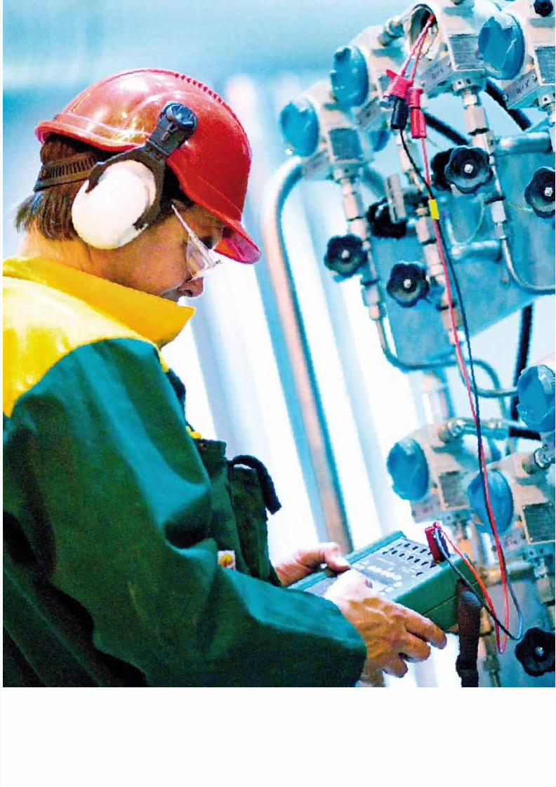
8/20/2019 Beamex Book Ultimate Calibration
http://slidepdf.com/reader/full/beamex-book-ultimate-calibration 56/204

8/20/2019 Beamex Book Ultimate Calibration
http://slidepdf.com/reader/full/beamex-book-ultimate-calibration 57/204
57
T
oday’s modern process plants, production processes and quality
systems, put new and tight requirements on the accuracy of
process instruments and on process control.
Quality systems, such as the ISO9000 and ISO14000 series of qualitystandards, call for systematic and well-documented calibrations, with
regard to accuracy, repeatability, uncertainty, confidence levels etc.
Does this mean that the electricians and instrumentation people
should be calibration experts? Not really, but this topic should
not be ignored. Fortunately, modern calibration techniques and
calibration systems have made it easier to fulf ill the requirements on
instrumentation calibration and maintenance in a productive way.
However, some understanding of the techniques, terminology and
methods involved in calibration must be known and understood in
order to perform according to International Quality Systems.
1. What is calibration and why calibrate
Calibration can briefly be described as an activity where the
instrument being tested is compared to a known reference value, i.e.
calibrator. The keywords here are ‘known reference’, which means
that the calibrator used should have a valid, traceable calibration
certificate.
To be able to answer the question why calibrate, we must first
determine what measurement is and why measuring is necessary.
Traceable and efficient calibrations
in the process industry
Calibration can briefly be
described as an activity where theinstrument
being tested is compared
to a known reference
value, i.e. calibrator.

8/20/2019 Beamex Book Ultimate Calibration
http://slidepdf.com/reader/full/beamex-book-ultimate-calibration 58/204
58
WHAT IS MEASUREMENT?
In technical standards terms the word measurement has been
defined as:
“A set of experimental operations for the purpose of determining
the value of a quantity.”
What is then the value of quantity? According to the standards
the true value of a quantity is:
“The value which characterizes a quantity perfectly defined
during the conditions which exist at the moment when the value
is observed. Note: the true value of a quantity is an ideal concept
and, in general, it cannot be known.”
Therefore all instruments display false indications!
HIERARCHYOF ACCURACY
TRUE VALUE
Process instrumentation
Instr. Departments
House and working standards
Authorized
Laboratories
International
National standard
A set of experimental
operations for the
purpose of determining
the value of a quantity.

8/20/2019 Beamex Book Ultimate Calibration
http://slidepdf.com/reader/full/beamex-book-ultimate-calibration 59/204
59
2. Why measure?
The purpose of a process plant is to convert raw material, energy,
manpower and capital into products in the best possible way. This
conversion always involves optimizing, which must be done better
than the competitors. In practice, optimization is done by means ofprocess automation. Anyhow, regardless of how advanced the process
automation system is, the control cannot be better than the quality of
measurements from the process.
3. Why calibrate
The primary reason for calibrating is based on the fact that even the
best measuring instruments lack in absolute stability, in other words,
The primary reason for
calibrating is based on
the fact that even the bestmeasuring instruments
lack in absolute stability, in
other words, they drift and
lose their ability to give
accurate measurements.
EVERYTHING IS BASEDON MEASUREMENTS
PROCESSProductionFactors
Products
MEASUREMENTS
MEASUREMENTS
CONTROLS
ADJUSTMENTS
PROCESS CONTROL SYSTEM
INSTRUMENTATION
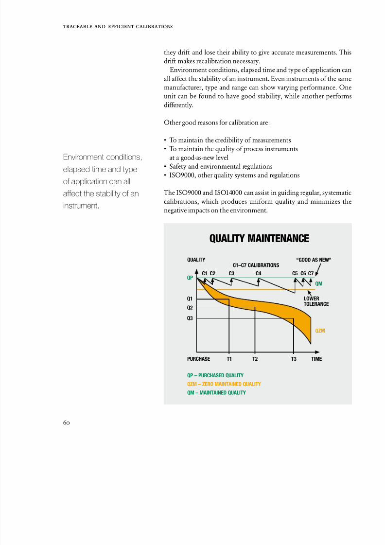
8/20/2019 Beamex Book Ultimate Calibration
http://slidepdf.com/reader/full/beamex-book-ultimate-calibration 60/204
60
they drift and lose their ability to give accurate measurements. Th
drift makes recalibration necessary.
Environment conditions, elapsed time and type of application ca
all affect the stability of an instrument. Even instruments of the sam
manufacturer, type and range can show varying performance. On
unit can be found to have good stability, while another performdifferently.
Other good reasons for calibration are:
• To maintain the credibility of measurements
• To maintain the quality of process instruments
at a good-as-new level
• Safety and environmental regulations
• ISO9000, other quality systems and regulations
The ISO9000 and ISO14000 can assist in guiding regular, systematcalibrations, which produces uniform quality and minimizes th
negative impacts on the environment.
C1–C7 CALIBRATIONS
PURCHASE
QP – PURCHASED QUALITY
QZM – ZERO MAINTAINED QUALITY
QM – MAINTAINED QUALITY
QUALITY
Q3
Q2
Q1
C1 C2 C3 C4 C5 C6QP
QM
QZM
T1 T2 T3 TIME
LOWERTOLERANCE
“GOOD AS NEW”
QUALITY MAINTENANCE
C7
Environment conditions,
elapsed time and type
of application can all
affect the stability of an
instrument.

8/20/2019 Beamex Book Ultimate Calibration
http://slidepdf.com/reader/full/beamex-book-ultimate-calibration 61/204
61
4. Traceability
Calibrations must be traceable. Traceability is a declaration stating
to which national standard a certain instrument has been compared.
5. Regulatory requirements for calibration
5.1 ISO9001: 2008
The organization determines the monitoring and measurements to
be performed, as well as the measuring devices needed to provide
evidence of a product’s conformity to determined standards.
The organization establishes the processes for ensuring that
measurements and monitoring are carried out and are carried out
in a manner consistent with the monitoring and measurement
requirements.
Where necessary, to ensure valid results, measuring equipmentis calibrated or verified with measurement standards traceable to
national or international standards at specified intervals. If no
such standards exist, the basis used for calibration or verification
is recorded; adjusted or re-adjusted as necessary; identified for the
determining of the calibration status; safeguarded against adjustments
that would invalidate the measurement result; protected from damage
and deterioration during handling, maintenance and storage.
In addition, the organization assesses and records the validity of
the previous measuring results when the equipment is found not to
conform to requirements. The organization then takes appropriate
action on the equipment and any product affected. Records of the
calibration and verification results are then maintained.
When used in the monitoring and measurement of specified
requirements, the ability of computer software to satisfy the intended
application is confirmed. This is done prior to initial use and
reconfirmed as necessary.
Note: See ISO 10012 for further information.
International
standards
National
standards
Reference
standards
Working
standards
Process
standards
SI-UNITS

8/20/2019 Beamex Book Ultimate Calibration
http://slidepdf.com/reader/full/beamex-book-ultimate-calibration 62/204
62
5.2 PHARMACEUTICAL (FDA, U.S. Food and Drug Administration)
Any pharmaceutical company that sells their products in the USA
must comply with FDA regulations, regardless of where the product
are manufactured.
• Calibration records must be maintained.
• Calibrations must be done in accordance with written, approved
procedures.
• There should be a record of the history of each instrument.
• All instrumentation should have a unique ID; all product, proces
and safety instruments should be physically tagged.
• A calibration period and error limits should be defined for each
instrument.
• Calibration standards should be traceable to national and
international standards.
• Calibration standards must be more accurate than the requiredaccuracy of the equipment being calibrated.
• All instruments used must be fit for purpose.
• There must be documented evidence that personnel involved in
the calibration process have been trained and are competent.
• Documented change management system must be in place.
• All electronic systems must comply with FDA’s 21 CFR Part 11.
• All of the above should be implemented in conjunction with
following regulations:
– 21 CFR Part 211 – “Current Good Manufacturing Practice
for Finished Pharmaceuticals”
– 21 CFR Part 11 – “Electronic Records; Electronic Signatures”
Software systems need features such as Electronic Signature, Aud
Trail, User Management, and Security System to be able to compl
with these regulations.
In such a system, the Electronic Signature is considered equivalent t
a hand-written signature. Users must understand their responsibilitie
once they give an electronic signature. An Audit Trail is require
to support change management. Audit Trails should record a
modifications, which add, edit, or delete data from an electroni
record.
Software systems
need features such as
Electronic Signature, Audit
Trail, User Management,
and Security System
to be able to comply
with these regulations.

8/20/2019 Beamex Book Ultimate Calibration
http://slidepdf.com/reader/full/beamex-book-ultimate-calibration 63/204
63
5.3 PHARMACEUTICAL (EU GMPs)
Any pharmaceutical company that sells their products in the European
Union must comply with EU GMPs, including Annex 11, regardless of
where the products are manufactured.
The requirements for EU GMPs are similar to those of the US FDA,as described in Section 5.2.
6. DEFINITIONS OF METROLOGICAL TERMS
Some metrological terms in association with the concept of calibration
are described in this section.
Quite a few of the following terms are also used on specification
sheets for calibrators. Please note that the definitions listed here are
simplified.
Calibration
An unknown measured signal is compared to a known reference
signal.
Validation
Validation of measurement and test methods (procedures) is generally
necessary to prove that the methods are suitable for the intended use.
Non-linearity
Non-linearity is the maximum deviation of a transducer’s output from
a defined straight line. Non-linearity is specified by the Terminal
Based method or the Best Fit Straight Line method.
Resolution
Resolution is the smallest interval that can be read between two
readings.
Validation of measure-
ment and test methods
(procedures) is generally
necessary to prove that
the methods are suitable
for the intended use.

8/20/2019 Beamex Book Ultimate Calibration
http://slidepdf.com/reader/full/beamex-book-ultimate-calibration 64/204
64
Sensitivity
Sensitivity is the smallest variation in input, which can be detected a
an output. Good resolution is required in order to detect sensitivity
Hysteresis
The deviation in output at any point within the instrument’s sensin
range, when first approaching this point with increasing values, an
then with decreasing values.
Repeatability
Repeatability is the capability of an instrument to give the sam
output among repeated inputs of the same value over a period of time
Repeatability is often expressed in the form of standard deviation.
Temperature coefficient
The change in a calibrator’s accuracy caused by changes in ambien
temperature (deviation from reference conditions). The temperatur
coefficient is usually expressed as % F.S. / °C or % of RDG/ °C.
Stability
Often referred to as drift, stability is expressed as the change i
percentage in the calibrated output of an instrument over a specifie
period, usually 90 days to 12 months, under normal operatin
conditions. Drift is usually given as a typical value.
Accuracy
Generally accuracy figures state the closeness of a measured valu
to a known reference value. The accuracy of the reference value
generally not included in the f igures. It must also be checked if erro
like non-linearity, hysteresis, temperature effects etc. are included i
the accuracy figures provided.
Accuracy is usually expressed % F.S. or % of RDG + adder. Th
difference between these two expressions is great. The only way t
compare accuracy presented in different ways is to calculate the tot
error at certain points.
Stability is expressed as
the change in percentage
in the calibrated output
of an instrument over a
specified period, usually
90 days to 12 months,
under normal operating
conditions.

8/20/2019 Beamex Book Ultimate Calibration
http://slidepdf.com/reader/full/beamex-book-ultimate-calibration 65/204
65
Uncertainty
Uncertainty is an estimate of the limits, at a given cover factor (or
confidence level), which contain the true value.
Uncertainty is evaluated according to either a “Type A” or a “Type
B” method. Type A involves the statistical analysis of a series ofmeasurements. In this case, uncertainty is calculated using Type A
uncertainties, i.e. the effects of these components include measurement
errors, which can vary in magnitude and in sign, in an unpredictable
manner. The other group of components, Type B, could be said to be of
a systematic nature. Systematic errors or effects remain constant during
the measurement. Examples of systematic effects include errors in
reference value, set-up of the measuring, ambient conditions, etc. Type
B uncertainty is used when the uncertainty of a single measurement
is expressed.
It should be noted that, in general, errors due to observer fallibility
cannot be accommodated within the calculation of uncertainty.Examples of such errors include: errors in recording data, errors in
calculation, or the use of inappropriate technology.
Type A uncertainty
The type A method of calculation can be applied when several
independent measurements have been made under the same
conditions. If there is suff icient resolution in the measurement, there
will be an observable difference in the values measured.
The standard deviation, often called the “root-mean-square
repeatability error”, for a series of measurements under the same
conditions, is used for calculation. Standard deviation is used as a
measure of the dispersion of values.
Type B uncertainty
Type B evaluation of uncertainty involves the use of other means
to calculate uncertainty, rather than applying statistical analysis of a
series of measurements.
It involves the evaluation of uncertainty using scientific judgement
based on all available information concerning the possible variables.
Values belonging to this category may be derived from:
It should be noted that, in
general, errors due to
observer fallibility cannot
be accommodated within
the calculation
of uncertainty.

8/20/2019 Beamex Book Ultimate Calibration
http://slidepdf.com/reader/full/beamex-book-ultimate-calibration 66/204
66
• Experience with or general knowledge of the behavior
and properties of relevant materials and instruments
• Ambient temperature
• Humidity
• Local gravity
• Atmospheric pressure• Uncertainty of the calibration standard
• Calibration procedures
• Method used to register calibration results
• Method to process calibration results
The proper use of the available information calls for insight base
on experience and general knowledge. It is a skill that can be learn
with practice. A well-based Type B evaluation of uncertainty ca
be as reliable as a Type A evaluation of uncertainty, especially i
a measurement situation where a Type A evaluation is based onl
on a comparatively small number of statistically independenmeasurements.
Expanded uncertainty
The EA has decided that calibration laboratories accredite
by members of the EA shall state an expanded uncertainty o
measurement obtained by multiplying the uncertainty by a coverag
factor k. In cases where normal (Gaussian) distribution can b
assumed, the standard coverage factor, k=2, should be used. Th
expanded uncertainty corresponds to a coverage probability (o
confidence level) of approximately 95%.
For uncertainty specifications, there must be a clear statement o
cover probability or confidence level. Usually one of the followin
confidence levels are used:
1 s = 68%
2 s = 95%
3 s = 99%
7. CALIBRATION MANAGEMENT Many companies do not pay enough attention to calibratio
management although it is a requirement e.g. in ISO9001: 2008
The maintenance management system may alert when calibration
For uncertainty
specifications, there
must be a clear state-
ment of cover probability
or confidence level.

8/20/2019 Beamex Book Ultimate Calibration
http://slidepdf.com/reader/full/beamex-book-ultimate-calibration 67/204
67
needed and then opens up a work order. Once the job has been done,
the work order will close and the maintenance system will be satisfied.
Unfortunately, what happens between opening and closing of the
work order is not documented very often. If something is documented,
it is usually in the form of a hand-written sheet that is then archived.
If the calibration results need to be examined at a later time, findingthe sheets requires a lot of effort.
Choosing professional tools for maintaining calibration records
and doing the calibrations can save a lot of time, effort and money.
An efficient calibration management system consists of calibration
management software and documenting calibrators.
Modern calibration management software can be a tool that
automates and simplifies calibration work at all levels. It automatically
creates a list of instruments waiting to be calibrated in the near future.
If the software is able to interface with other systems the scheduling
of calibrations can be done in the maintenance system from which
the work orders can be automatically loaded into the calibrationmanagement software.
When the technician is about to calibrate an instrument, (s)he simply
downloads the instrument details from the calibration management
software into the memory of a documenting calibrator; no printed
notes, etc. are needed. The “As Found” and “As Left” are saved in the
calibrator’s memory, and there is no need to write down anything
with pen.
The instrument’s measurement ranges and error limits are defined in
the software and also downloaded to the calibrator. Thus the calibrator
is able to detect if the calibration was passed or failed immediately after
the last calibration point was recorded. There is no need to make tricky
calculations manually in the field.
All this saves an extensive amount of time and prevents the user
from making mistakes. The increase in work productivity allows for
more calibrations to be carried out within the same period of time
as before. Depending on what process variable is calibrated and how
many calibration points are recorded, using automated tools can be 5
to 10 times faster compared to manual recording.
While the calibration results are uploaded onto the database, the
software automatically detects the calibrator that was used, and the
traceability chain is documented without requiring any further actions
from the user.
Calibration records, including the full calibration history of an
The instrument’s
measurement ranges
and error limits are
defined in the software
and also downloaded
to the calibrator.

8/20/2019 Beamex Book Ultimate Calibration
http://slidepdf.com/reader/full/beamex-book-ultimate-calibration 68/204
68
instrument, are kept in the database; therefore accessing previou
results is also possible in just a few seconds. When an instrument ha
been calibrated several times, software displays the “History Trend
which assists in determining whether or not the calibration perio
should be changed.
One of today’s trends is to move towards to a paperless office. If thcalibration management software includes the right tools, it is possib
to manage calibration records on computer without producing an
papers. If paper copies of certificates are preferred, printing them mus
of course, be possible. When all calibration related data is located i
a single database the software is obviously able to create calibratio
related reports and documents.
Today’s documenting calibrators are capable of calibrating man
process signals. It is not very uncommon to have a calibrator tha
calibrates pressure, temperature and electrical signals includin
frequency and pulses. In addition to the conventional mA output o
a transmitter, modern calibrators can also read HART, FoundatioFieldbus or Profibus output of the transmitters, and they can be eve
used for configuring these “smart” transmitters.
Implementing a modern calibration management system benefit
everybody who has anything to do with instrumentation. For instanc
the maintenance manager can use it as a calibration planning an
decision-making tool for tracking and managing all calibration relate
activities.
When an auditor comes for a visit, QA will find a calibratio
management system useful. The requested calibration records ca
be viewed on screen with a couple mouse clicks. If a calibrator drift
out of its specifications, it is possible to use a “reverse traceabilit
report” to get a list of instruments that have been calibrated with tha
calibrator.
Good calibration tools help technicians work more efficiently an
accurately. If the system manufacturer has paid attention usability
the system is easy to learn and use. When many tasks are automated
the users can concentrate on their primary job.
Transferring to a new calibration system may sound like a huge tas
and it can be a huge task. There are probably thousands of instrumen
that need to be entered into the database and all the details must b
checked and verified before the system is up and running. Althoug
there is a lot of data involved, it does not mean the job is an enormou
one.
Implementing a modern
calibration management
system benefits
everybody who has
anything to do with
instrumentation.

8/20/2019 Beamex Book Ultimate Calibration
http://slidepdf.com/reader/full/beamex-book-ultimate-calibration 69/204
69
A good, automated
calibration system
reduces workload.
CONCLUSION
A good, automated calibration system reduces workload
because it carries out tasks faster, more accurately and with
better results than what could be reached with a manual system.
It assists in documenting, scheduling, planning, analyzing and
finally optimizing the calibration work.
References
[1] ISO9001: 2008 “Quality Management Systems.
Requirements”
[2] 21 CFR Part 11: “Electronic Records;
Electronic Signatures”
[3] 21 CFR Part 211: “Current Good Manufacturing Practice
for Finished Pharmaceuticals”
Nowadays most companies have instrumentation data in some type
of electronic format: as Excel spreadsheets, Maintenance databases,
etc. The vendor of the calibration system is most likely able to import
most of the existing data to the calibration database saving months
of work.

8/20/2019 Beamex Book Ultimate Calibration
http://slidepdf.com/reader/full/beamex-book-ultimate-calibration 70/204

8/20/2019 Beamex Book Ultimate Calibration
http://slidepdf.com/reader/full/beamex-book-ultimate-calibration 71/204
CalibrationManagement and
Maintenance

8/20/2019 Beamex Book Ultimate Calibration
http://slidepdf.com/reader/full/beamex-book-ultimate-calibration 72/204

8/20/2019 Beamex Book Ultimate Calibration
http://slidepdf.com/reader/full/beamex-book-ultimate-calibration 73/204
73
Calibration can be briefly described as an activity where the
instrument being tested is compared to a known reference
value. At the simplest level, calibration is a comparison between
measurements – one of known magnitude or correctness made or set
with one device, and another measurement made in as similar a way aspossible with a second device. The device with the known or assigned
correctness is called the standard. The second device is the unit under
test or test instrument.
Calibration is often required with a new instrument or when a
specified time period or a specified number of operating hours
has elapsed. In addition, calibration is usually carried out when an
instrument has been subjected to an unexpected shock or vibration
that may have put it out of its specif ied limits.
Calibration in industrial applications
When a sensor or instrument experiences temperature variations or
physical stress over time, its performance will invariably begin to
decline, which is known as ‘drift’. This means that measurement data
from the sensor becomes unreliable and could even affect the quality
of a company’s production.
Although drift cannot be completely eliminated, it can be discovered
and rectified via calibration. The purpose of calibration is to determine
how accurate an instrument or sensor is. Although most instruments
provide high accuracy these days, regulatory bodies often need to
know just how inaccurate a particular instrument is and whether it
drifts in and out of specified tolerance over time.
Why Calibrate?
What is the risk of not calibrating?
Although drift cannot be
completely eliminated, it
can be discovered and
rectified via calibration.

8/20/2019 Beamex Book Ultimate Calibration
http://slidepdf.com/reader/full/beamex-book-ultimate-calibration 74/204
74
The costs and risks of not calibrating
Unfortunately, calibration has costs associated with it and in uncertai
economic times, this activity can often become neglected or th
interval between calibration checks on instruments can be extended i
order to cut costs or simply through a lack of resources or manpoweHowever, neglecting calibration can lead to unscheduled productio
or machine downtime, product and process quality issues or eve
product recalls and rework.
Furthermore, if the instrument is critical to a process or is locate
in a hazardous area, allowing that sensor to drift over time coul
potentially result in a risk to employee safety. Similarly, an end produ
manufactured by a plant with poorly calibrated instruments coul
present a risk to both consumers and customers. In certain situation
this may even lead to a company losing its license to operate due t
company not meeting its regulatory requirements. This is particularl
true for the food and beverage sector and for pharmaceuticamanufacturers.
Weighing instruments also need to be calibrated regularly
Determining the correct mass of a product or material is particularl
important for companies that supply steel, paper and pulp, powe
aviation companies, harbors and retail outlets, who invoice custome
based on the mass of what they supply (fiscal metering). Thes
companies need to prove not only that the mass is accurate but als
that the equipment producing the readings was correctly calibrated
Invoicing in these industries is often based on process measurement
There is therefore a growing need to have the metrological quality o
these weighing instruments confirmed by calibration.
Product manufacturing also depends on accurate masses and s
laboratories and production departments in the food and beverage
oil and gas, energy, chemical and pharmaceutical industries, also nee
to calibrate their weighing instruments.
Why is calibration important?
Calibration ensures that instrument drift is minimized. Even th
highest quality instruments will drift over time and lose their abilit
to provide accurate measurements. It is therefore critical that a
instruments are calibrated at appropriate intervals.
The stability of an instrument very much depends on its applicatio
and the environment it operates in. Fluctuating temperatures, hars
Even the highest quality
instruments will drif t
over time and lose their
ability to provide accurate
measurements.

8/20/2019 Beamex Book Ultimate Calibration
http://slidepdf.com/reader/full/beamex-book-ultimate-calibration 75/204
75
manufacturing conditions (dust and dirt) and elapsed time are all
contributing factors here. Even instruments manufactured by the same
supplier can vary in their performance over time.
Calibration also ensures that product or batch quality remains high
and consistent over time. Quality systems such as ISO 9001, ISO 9002
and ISO 14001 require systematic, well-documented calibrations withrespect to accuracy, repeatability, uncertainty and confidence levels.
This affects all process manufacturers.
Armando Rivero Rubalcaba is head of Instrumentation at beer
producer Heineken (Spain). He comments: “For Heineken, the quality
of the beer is a number one priority. All the plants in Spain have
received ISO 9001 and ISO 14001 certifications, in addition to the BRC
certificate of food safety. We must therefore ensure that all processes
correspond to the planned characteristics. The role of calibration is very
important to ensure the quality and safety of the processes.”
Pharmaceutical manufacturers must follow current Good
Manufacturing Practices, GMP, requires that calibration records aremaintained and calibrations have to be carried out in accordance
with written, approved procedures. Typically, each instrument has a
master history record and a unique ID. All product, process and safety
instruments should also be physically tagged.
Furthermore, a calibration interval and error limits should be
defined for each instrument and standards should be traceable to
national and international standards. Standards must also be more
accurate than the required accuracy of the equipment being calibrated.
On the people side, there must be documented evidence that
employees involved in the calibration process have been properly
trained and competent. The company must also have a documented
change management system in place, with all electronic systems
complying with FDA regulations 21 CFR Part 11.
In the power generation, energy and utilities industries, instrument
calibration can help to optimize a company’s production process or to
increase the plant’s production capacity. For example, at the Almaraz
Nuclear Power Plant in Spain, by improving the measurement of
reactor power parameters from 2% to 0.4%, enabled the reactor power
in each unit to be increased by 1.6%, which has a significant effect on
annual production capacity.
Safety is another important reason to calibrate instruments.
Production environments are potentially high risk areas for employees
and can involve high temperatures and high pressures. Incorrect
measurements in a hazardous area could lead to serious consequences,
The role of calibration is
very important to ensure
the quality and safety of
the processes.

8/20/2019 Beamex Book Ultimate Calibration
http://slidepdf.com/reader/full/beamex-book-ultimate-calibration 76/204
76
Calibration is of great
importance, especially
from the viewpoint of
production safety and
quality of the final product.
particularly in the oil and gas, petrochemicals and chemicals sector
Similarly, manufacturers of food and beverage or pharmaceutica
products could put their customers’ lives at risk by neglecting t
calibrate their process instruments.
Heikki Karhe is a measurement technician at the tyre manufacture
Nokian Tyres. As he puts it: “Calibration is of great importanceespecially from the viewpoint of production safety and quality o
the final product. Preparation of the right rubber mixture is precisio
work and a sample is taken from each rubber mixture to ensure quality
Measuring instruments that yield wrong values could easily ruin th
final product. The factory is also full of pressure instruments and so
is also important for the safety of the workers that those instrumen
show the right values.”
Neglecting to calibrate process instruments can also affect
company’s bottom line profits. This is particularly true if sale
invoicing is based on accurate process measurements, for example
weighing scales or gas conversion devices. Indeed, according to recenresearch by Nielsen Research/ ATS Studies, poor quality calibratio
is on average costing manufacturers more than 1.7 million US dolla
every year. When only large companies with revenues of more than
billion US dollars are considered, this figure rises dramatically to mor
than 4 million US dollars per year.
Proper invoicing is therefore critical to energy and utilitie
companies. As Jacek Midera, measurement specialist at Mazovian Ga
Company states: “Most importantly, accurate measurements ensur
proper billing. The impact of even a small measurement error ca
be tremendous in terms of lost revenue. Customers want to pay fo
the exact amount of gas they’ve received. Therefore, gas conversio
devices must be extremely accurate in measuring delivered gas. Th
means that requirements for the calibrators are especially high.”
Today, controlling emissions is another critical factor for man
process manufacturers. Calibrating instruments can help to mak
combustion more efficient in industrial ovens and furnaces. Th
latest Government regulations relating to carbon emissions may als
require that companies calibrate specific instruments on a regula
basis, including sensors used for measuring CO2 and NO
X emission
As Ed de Jong, Instrument Maintenance Engineer at She
(Netherlands) explains: “Until recently, calibration was mainly drive
by economic motives: even the smallest of errors in delivery quantitie
are unacceptable in Shell’s operation due to the vast sums of mone

8/20/2019 Beamex Book Ultimate Calibration
http://slidepdf.com/reader/full/beamex-book-ultimate-calibration 77/204
77
involved for both customers and governments [fiscal metering].
Nowadays, calibration has an important role especially for the license
to operate. Government regulations demand that specific instruments
must be calibrated, for example, instruments related to CO2 and NO
X
emissions.”
Common misconceptions
There are some common misconceptions when it comes to instrument
calibration. For example, some manufacturers claim that they do not
need to calibrate their fieldbus instruments because they are digital
and so are always accurate and correct. This is simply not true. The
main difference between fieldbus and conventional transmitters
is that the output signal is a fully digital fieldbus signal. Changing
the output signal does not change the need for periodic calibration.
Although fieldbus transmitters have been improved in terms of their
measurement accuracy when compared to analogue transmitters, thisdoes not eliminate the need for calibration.
Another common misunderstanding is that new instruments do
not require calibration. Again, this is not true. Just because a sensor is
newly installed does not mean that it will perform within the required
specifications. By calibrating an instrument before installation,
a company is able to enter all the necessary instrument data to its
calibration database or calibration management software, as well as
begin to monitor the stability or drift of the instrument over time.
When to calibrate
Due to drift, all instruments require calibrating at set intervals. How
often they are calibrated depends on a number of factors. First, the
manufacturer of the instrument will provide a recommended calibration
interval. This interval may be decreased if the instrument is being used
in a critical process or application. Quality standards may also dictate
how often a pressure or temperature sensor needs calibrating.
The most effective method of determining when an instrument
requires calibrating is to use some sort of history trend analysis. The
optimal calibration interval for different instruments can only be
determined with software-based history trend analysis. In this way,
highly stable sensors are not calibrated as often as those sensors that
are more susceptible to drift.
The most effective
method of determining
when an instrument
requires calibrating is to
use some sort of history
trend analysis.
8/20/2019 Beamex Book Ultimate Calibration
http://slidepdf.com/reader/full/beamex-book-ultimate-calibration 78/204
78
8/20/2019 Beamex Book Ultimate Calibration
http://slidepdf.com/reader/full/beamex-book-ultimate-calibration 79/204
79
Every manufacturing plant has some sort of system in place for
managing instrument calibration operations and data. Plant
instrumentation devices such as temperature sensors, pressure
transducers and weighing instruments – require regular calibration
to ensure they are performing and measuring to specif ied tolerances.However, different companies from a diverse range of industry
sectors use very different methods of managing these calibrations.
These methods differ greatly in terms of cost, quality, efficiency, and
accuracy of data and their level of automation.
Calibration software is one such tool that can be used to support and
guide calibration management activities, with documentation being
a critical part of this.
But in order to understand how software can help process plants
better manage their instrument calibrations, it is important to consider
the typical calibration management tasks that companies have to
undertake. There are five main areas here, comprising of planning
and decision-making; organisation; execution; documentation; and
analysis.
Careful planning and decision-making is important. All plant
instruments and measurement devices need to be listed, then classified
into ‘critical’ and ‘non-critical’ devices. Once this has been agreed,
the calibration range and required tolerances need to be identified.
Decisions then need to be made regarding the calibration interval for
each instrument. The creation and approval of standard operating
procedures (SOPs) for each device is then required, followed by the
selection of suitable calibration methods and tools for execution of
these methods. Finally, the company must identify current calibration
status for every instrument across the plant.
Why use software forcalibration management?
Calibration software
is one such tool that
can be used to support
and guide calibration
management activities,
with documentation being
a critical part of this.
8/20/2019 Beamex Book Ultimate Calibration
http://slidepdf.com/reader/full/beamex-book-ultimate-calibration 80/204
80
The next stage, organisation, involves training the company
calibration staff – typically maintenance technicians, servic
engineers, process and quality engineers and managers – in using th
chosen tools and how to follow the approved SOPs. Resources the
have to be organised and assigned to actually carry out the schedule
calibration tasks.The execution stage involves supervising the assigned calibratio
tasks. Staff carrying out these activities must follow the appropriat
instructions before calibrating the device, including any associate
safety procedures. The calibration is then executed according to the plan
although further instructions may need to be followed after calibration
The documentation and storage of calibration results typicall
involves signing and approving all calibration records that are generated
The next calibration tasks then have to be scheduled, calibration labe
need to be created and pasted, then created documents copied an
archived.
Based on the calibration results, companies then have to analyse thdata to see if any corrective action needs to be taken. The effectivene
of calibration needs to be reviewed and calibration intervals checked
These intervals may need to be adjusted based on archived calibratio
history. If, for example, a sensor drifts out of its specification range
the consequences could be disastrous for the plant, resulting in costl
production downtime, a safety problem or leading to batches of inferio
quality goods being produced, which may then have to be scrapped.
Documentation
Documentation is a very important part of a calibration managemen
process. ISO 9001:2008 and the FDA both state that calibratio
records must be maintained and that calibration must be carried ou
according to written, approved procedures.
This means an instrument engineer can spend as much as 50 pe
cent of his or her time on documentation and paperwork – time tha
could be better spent on other value-added activities. This paperwor
typically involves preparing calibration instructions to help fiel
engineers; making notes of calibration results in the field; an
documenting and archiving calibration data.
Imagine how long and difficult a task this is if the plant ha
thousands of instruments that require calibrating on at least a six
monthly basis? The amount of manual documentation increase
almost exponentially!
All plant instruments and
measurement devices
need to be listed, then
classified into ‘critical’
and ‘non-critical’ devices.

8/20/2019 Beamex Book Ultimate Calibration
http://slidepdf.com/reader/full/beamex-book-ultimate-calibration 81/204
81
When it comes to the volume of documentation required, different
industry sectors have different requirements and regulations. In the
Power & Energy sector, for example, just under a third of companies
(with 500+ employees) typically have more than 5,000 instruments
that require calibrating. 42 per cent of companies perform more than
2,000 calibrations each year.In the highly regulated pharmaceuticals sector, a massive 75 per cent
of companies carry out more than 2,000 calibrations per year. Oil,
Gas & Petrochemicals is similarly high, with 55 per cent of companies
performing more than 2,000 calibrations each year. The percentage
is still quite high in the food & beverage sector, where 21 per cent of
firms said they calibrated their instruments more than 2,000 times
every year. This equates to a huge amount of paperwork for any process
plant.
The figures outlined appear to suggest that companies really
do require some sort of software tool to help them manage their
instrument calibration processes and all associated documentation.However, the picture in reality can be very different.
Only a quarter of companies use calibration software
In Beamex’s own Calibration Study carried out recently, a mere 25
per cent of companies with 500+ employees (across the industry
sectors mentioned above) said that they did use specialist calibration
management software. Many other companies said that they relied
on generic spreadsheets and/or databases for this, whilst others used
a calibration module within an existing Computerised Maintenance
Management System (CMMS). A signif icant proportion (almost 20 per
cent) of those surveyed said they used a manual, paper-based system.
Any type of paper-based calibration system will be prone to human
error. Noting down calibration results by hand in the f ield and then
transferring these results into a spreadsheet back at the office may
seem archaic, but many firms still do this. Furthermore, analysis of
paper-based systems and spreadsheets can be almost impossible, let
alone time consuming.
In a recent survey conducted by Control Magazine, 40 per cent of
companies surveyed said that they calculated calibration intervals by
using historical trend analysis – which is encouraging. However, many
of these firms said they were doing it without any sort of calibration
software to assist them. The other 60 per cent of companies determined
This means an instrument
engineer can spend
as much as 50 per
cent of his or her time
on documentation and
paperwork – time that
could be better spent
on other value-added
activities.
8/20/2019 Beamex Book Ultimate Calibration
http://slidepdf.com/reader/full/beamex-book-ultimate-calibration 82/204
82
instrument calibration intervals based on either the manufacturer’s ow
recommendation, or they used a uniform interval across the plant fo
all instruments. Neither method is ideal in practice. Companies coul
save so much time and reduce costs by using calibration managemen
software to analyse historical trends and calibration results.
Using software for calibration management enables faster, easier anmore accurate analysis of calibration records and identifying historica
trends. Plants can therefore reduce costs and optimise calibratio
intervals by reducing calibration frequency when this is possible, o
by increasing the frequency where necessary.
For example, for improved safety, a process plant may find
necessary to increase the frequency of some sensors that are located i
a hazardous, potentially explosive area of the manufacturing plant.
Just as important, by analysing the calibration history of a flo
meter that is located in a ‘non-critical’ area of the plant, the compan
may be able to decrease the frequency of calibration, saving time an
resources. Rather than rely on the manufacturer’s recommendation focalibration intervals, the plant may be able to extend these intervals b
looking closely at historical trends provided by calibration managemen
software. Instrument ‘drift’ can be monitored closely over a period o
time and then decisions taken confidently with respect to amendin
the calibration interval.
Regardless of industry sector, there seems to be some genera
challenges that companies face when it comes to calibratio
management.
The number of instruments and the total number of periodi
calibrations that these devices require can be several thousand per yea
How to plan and keep track of each instrument’s calibration procedure
means that planning and scheduling is important. Furthermore, ever
instrument calibration has to be documented and these documen
need to be easily accessible for audit purposes.
Paper-based systems
These systems typically involve hand-written documents. Typicall
this might include engineers using pens and paper to record calibratio
results while out in the field. On returning to the off ice, these note
are then tidied up or transferred to another paper document, afte
which they are archived as paper documents.
While using a manual, paper-based system requires little or n
Using software for
calibration management
enables faster, easier and
more accurate analysis
of calibration records
and identifying historical
trends.

8/20/2019 Beamex Book Ultimate Calibration
http://slidepdf.com/reader/full/beamex-book-ultimate-calibration 83/204
83
investment, it is very labour-intensive and means that historical trend
analysis becomes very diff icult to carry out. In addition, the calibration
data is not easily accessible. The system is time consuming, soaks up a
lot of resources and typing errors are commonplace. Dual effort and
re-keying of calibration data are also significant costs here.
In-house legacy systems (spreadsheets, databases, etc.)
Although certainly a step in the right direction, using an in-house
legacy system to manage calibrations has its drawbacks. In these
systems, calibration data is typically entered manually into a
spreadsheet or database. The data is stored in electronic format, but
the recording of calibration information is still t ime-consuming and
typing errors are common. Also, the calibration process itself cannot
be automated. For example, automatic alarms cannot be set up on
instruments that are due for calibration.
Calibration module of a CMMS
Many plants have already invested in a Computerised Maintenance
Management (CMM) system and so continue to use this for calibration
management. Plant hierarchy and works orders can be stored in the
CMM system, but the calibration cannot be automated because the
system is not able to communicate with ‘smart’ calibrators.
Furthermore, CMM systems are not designed to manage calibrations
and so often only provide the minimum calibration functionality, such
as the scheduling of tasks and entry of calibration results. Although
instrument data can be stored and managed efficiently in the plant’s
database, the level of automation is still low. In addition, the CMM
system may not meet the regulatory requirements (e.g. FDA) for
managing calibration records.
Calibration software
With specialist calibration management software, users are provided
with an easy-to-use Windows Explorer-like interface. The software
manages and stores all instrument and calibration data. This
includes the planning and scheduling of calibration work; analysis
and optimisation of calibration frequency; production of reports,
certificates and labels; communication with smart calibrators; and
Regardless of industry
sector, there seems to be
some general challenges
that companies face
when it comes to
calibration management.

8/20/2019 Beamex Book Ultimate Calibration
http://slidepdf.com/reader/full/beamex-book-ultimate-calibration 84/204
84
easy integration with CMM systems such as SAP and Maximo. Th
result is a streamlined, automated calibration process, which improve
quality, plant productivity and eff iciency.
Benefits of using calibration softwareWith software-based calibration management, planning and decision
making are improved. Procedures and calibration strategies can b
planned and all calibration assets managed by the software. Position
device and calibrator databases are maintained, while automatic alert
for scheduled calibrations can be set up.
Organisation also improves. The system no longer requires pens an
paper. Calibration instructions are created using the software to guid
engineers through the calibration process. These instructions can als
be downloaded to a technician’s handheld documenting calibrato
while they are in the field.
Execution is more efficient and errors are eliminated. Usinsoftware-based calibration management systems in conjunction wit
documenting calibrators means that calibration results can be store
in the calibrator’s memory, then automatically uploaded back to th
calibration software. There is no re-keying of calibration results from
a notebook to a database or spreadsheet. Human error is minimise
and engineers are freed up to perform more strategic analysis or othe
important activities.
Documentation is also improved. The software generates report
automatically and all calibration data is stored in one database rathe
than multiple disparate systems. Calibration certif icates, reports an
labels can all be printed out on paper or sent in electronic format.
Analysis becomes easier too, enabling engineers to optimise calibratio
intervals using the software’s History Trend function.
Also, when a plant is being audited, calibration software ca
facilitate both the preparation and the audit itself. Locating record
and verifying that the system works is effortless when compared t
traditional calibration record keeping.
Regulatory organisations and standards such as FDA and ISO
place demanding requirements on the recording of calibration data
Calibration software has many functions that help in meeting thes
requirements, such as Change Management, Audit Trail and Electroni
Signature functions. The Change Management feature in Beamex
CMX software, for example, complies with FDA requirements.
Using software for
calibration management
enables faster, easier and
more accurate analysis
of calibration records
and identifying historical
trends.
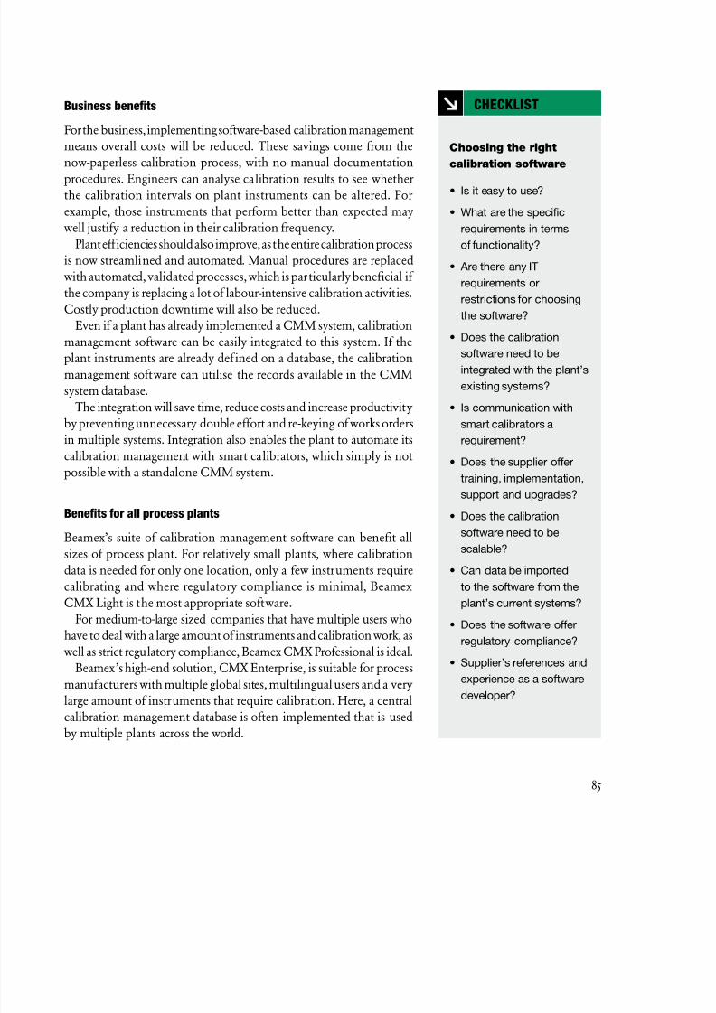
8/20/2019 Beamex Book Ultimate Calibration
http://slidepdf.com/reader/full/beamex-book-ultimate-calibration 85/204
85
Business benefits
For the business, implementing software-based calibration management
means overall costs will be reduced. These savings come from the
now-paperless calibration process, with no manual documentation
procedures. Engineers can analyse calibration results to see whetherthe calibration intervals on plant instruments can be altered. For
example, those instruments that perform better than expected may
well justify a reduction in their calibration frequency.
Plant efficiencies should also improve, as the entire calibration process
is now streamlined and automated. Manual procedures are replaced
with automated, validated processes, which is particularly beneficial if
the company is replacing a lot of labour-intensive calibration activities.
Costly production downtime will also be reduced.
Even if a plant has already implemented a CMM system, calibration
management software can be easily integrated to this system. If the
plant instruments are already def ined on a database, the calibrationmanagement software can utilise the records available in the CMM
system database.
The integration will save time, reduce costs and increase productivity
by preventing unnecessary double effort and re-keying of works orders
in multiple systems. Integration also enables the plant to automate its
calibration management with smart calibrators, which simply is not
possible with a standalone CMM system.
Benefits for all process plants
Beamex’s suite of calibration management software can benefit all
sizes of process plant. For relatively small plants, where calibration
data is needed for only one location, only a few instruments require
calibrating and where regulatory compliance is minimal, Beamex
CMX Light is the most appropriate software.
For medium-to-large sized companies that have multiple users who
have to deal with a large amount of instruments and calibration work, as
well as strict regulatory compliance, Beamex CMX Professional is ideal.
Beamex’s high-end solution, CMX Enterprise, is suitable for process
manufacturers with multiple global sites, multilingual users and a very
large amount of instruments that require calibration. Here, a central
calibration management database is often implemented that is used
by multiple plants across the world.
Choosing the right
calibration software
• Is it easy to use?
• What are the specific
requirements in terms
of functionality?
• Are there any IT
requirements or
restrictions for choosing
the software?
• Does the calibration
software need to beintegrated with the plant’s
existing systems?
• Is communication with
smart calibrators a
requirement?
• Does the supplier offer
training, implementation,
support and upgrades?
• Does the calibration
software need to bescalable?
• Can data be imported
to the software from the
plant’s current systems?
• Does the software offer
regulatory compliance?
• Supplier’s references and
experience as a software
developer?
CHECKLIST

8/20/2019 Beamex Book Ultimate Calibration
http://slidepdf.com/reader/full/beamex-book-ultimate-calibration 86/204
86
Beamex users
Beamex conducted recently a survey of its customers, across a
industry sectors. The results showed that 82% of CMX Calibratio
software customers said that using Beamex products had resulted i
cost savings in some part of their operations.94% of CMX users stated that using Beamex products had improve
the efficiency of their calibration processes, whilst 92% said that usin
CMX had improved the quality of their calibration system.
Summary
Every type of process plant, regardless of industry sector, can benef
from implementing specialist calibration management software
Compared to traditional, paper-based systems, in-house built legac
calibration systems or calibration modules with CMM systems, usin
dedicated calibration management software results in improvequality, increased productivity and reduced costs of the entir
calibration process.
Despite these benefits, only one quarter of companies who nee
to manage instrument calibrations actually use software designed fo
that purpose.
SUMMARY
Calibration software
improves calibration
management tasks
in all these areas
• Planning &
decision-making
• Organisation
• Execution
• Documentation
• Analysis
The business benefits
of using software for
calibration management
• Cost reduction
• Quality improvements
• Increase in efficiency

8/20/2019 Beamex Book Ultimate Calibration
http://slidepdf.com/reader/full/beamex-book-ultimate-calibration 87/204
87

8/20/2019 Beamex Book Ultimate Calibration
http://slidepdf.com/reader/full/beamex-book-ultimate-calibration 88/204
8/20/2019 Beamex Book Ultimate Calibration
http://slidepdf.com/reader/full/beamex-book-ultimate-calibration 89/204
89
Plants can improve their efficiency and reduce costs by performing
calibration history trend analysis. By doing it, a plant is able
to define which instruments can be calibrated less frequentlyand which should be calibrated more frequently. Calibration
history trend analysis is only possible with calibration software
that provides this functionality.
Adjusting calibration intervals based on history trend analysis
Manufacturing plants need to be absolutely confident that their
instrumentation products – temperature sensors, pressure transducers,
flow meters and the like – are performing and measuring to specified
tolerances. If sensors drift out of their specification range, the
consequences can be disastrous for a plant, resulting in costly production
downtime, safety issues or possibly leading to batches of inferior quality
goods being produced, which then have to be scrapped.
Most process manufacturing plants will have some sort of
maintenance plan or schedule in place, which ensures that all
instruments used across the site are calibrated at the appropriate times.
However, with increasing demands and cost issues being placed on
manufacturers these days, the time and resources required to carry
out these calibration checks are often scarce. This can sometimes lead
to instruments being prioritised for calibration, with those deemed
critical enough receiving the required regular checks, but for other
sensors that are deemed less critical to production, being calibrated
less frequently or not at all.
How often should
instruments be calibrated
Plants can improve their
efficiencies and reducecosts by using calibration
‘history trend analysis’,
a function available within
Beamex ® CMX calibration
software.

8/20/2019 Beamex Book Ultimate Calibration
http://slidepdf.com/reader/full/beamex-book-ultimate-calibration 90/204
90
But plants can improve their efficiencies and reduce costs b
using calibration ‘history trend analysis’, a function available withi
Beamex® CMX calibration software. With this function, the plan
can analyze whether it should increase or decrease the calibratio
frequency for all its instruments.
Cost savings can be achieved in several ways. First, by calibratinless frequently where instruments appear to be highly stable accordin
to their calibration history. Second, by calibrating instruments mor
often when they are located in critical areas of the plant, ensurin
that instruments are checked and corrected before they drift ou
of tolerance. This type of practise is common in companies tha
employ an effective ‘Preventive Maintenance’ regime. The analyse
of historical trends and how a pressure sensor, for example, drifts i
and out of tolerance over a given time period, is only possible wit
calibration software that provides this type of functionality.
Current practices in process plants
But in reality, how often do process plants actually calibrate the
instruments and how does a maintenance manager or engineer kno
how often to calibrate a particular sensor?
In March 2010, Beamex conducted a survey that asked proces
manufacturing companies how many instruments in their plan
required calibrating and the frequency with which these instrumen
had to be calibrated. The survey covered all industry sectors, includin
pharmaceuticals, chemicals, power and energy, manufacturing
service, food and beverage, oil and gas, paper and pulp.
Interestingly, the survey showed that from all industry sectors, 56%
of the respondents said they calibrated their instruments no mor
than once a year.
However, in the pharmaceuticals sector, 59% said they calibrate
once a year and 30% said they calibrated twice a year.
Perhaps unsurprisingly, due to it being a highly regulated industry
the study proved also that the pharmaceuticals sector typicall
possesses a significantly higher number of instruments per plan
that require calibrating. In addition, these plants also calibrate the
instruments more frequently than other industry sectors.
Sensors that are found
to be highly stable do not
need to be re-calibrated
as often as sensors that
tend to drift.

8/20/2019 Beamex Book Ultimate Calibration
http://slidepdf.com/reader/full/beamex-book-ultimate-calibration 91/204
91
The benefits of analyzing calibration history trends
But regardless of the industry sector, by analysing an instrument’s
drift over time (ie. the historical trend) companies can reduce
costs and improve their efficiencies. Pertti Mäki is Area Sales
Manager at Beamex. He specialises in selling the Beamex® CMXto different customers across all industry sectors. He comments:
“The largest savings from using the History Trend Option are in the
pharmaceuticals sector, without doubt, but all industry sectors can
benefit from using the software tool, which helps companies identify
the optimal calibration intervals for instruments.”
The trick, says Mäki, is determining which sensors should be re-
calibrated after a few days, weeks, or even years of operation and which
can be left for longer periods, without of course sacrificing the quality
of the product or process or the safety of the plant and its employees.
Doing this, he says, enables maintenance staff to concentrate their
efforts only where they are needed, therefore eliminating unnecessarycalibration effort and time.
But there are other, perhaps less obvious benefits of looking at the
historical drift over time of a particular sensor or set of measuring
instruments. As Mäki explains: “When an engineer buys a particular
sensor, the supplier provides a technical specification that includes details
on what the maximum drift of that sensor should be over a given time
period. With CMX’s History Trend Option, the engineer can now verify
that the sensor he or she has purchased, actually performed within the
specified tolerance over a certain time period. If it hasn’t, the engineer
now has data to present to the supplier to support his findings.”
But that’s not all. The History Trend function also means that a
plant can now compare the quality or performance of different sensors
from multiple manufacturers in a given location or set of process
conditions. This makes it an invaluable tool for maintenance or quality
personnel who, in setting up a new process line for example, can use
the functionality to compare different sensor types to see which one
best suits the new process.
Calibration software such as CMX can also help with the planning
of calibration operations. Calibration schedules take into account
the accuracy required for a particular sensor and the length of time
during which it has previously been able to maintain that degree of
accuracy. Sensors that are found to be highly stable do not need to be
re-calibrated as often as sensors that tend to drift.
The function enables
users to plan the optimal
calibration intervals for
their instruments.

8/20/2019 Beamex Book Ultimate Calibration
http://slidepdf.com/reader/full/beamex-book-ultimate-calibration 92/204
92
The History Trend function enables users to plan the optima
calibration intervals for their instruments. Once implemented
maintenance personnel, for example, can analyze an instrument’s drif
over a certain time period. History Trend displays the instrument
drift over a given period both numerically and graphically. Based o
this information, it is then possible to make decisions and conclusionregarding the optimal calibration interval and the quality of th
instruments with respect to measurement performance.
The ‘History Trend’ window enables users to view key figures o
several calibration events simultaneously, allowing to evaluate th
calibrations of a position or a device for a longer time period compare
to the normal calibration result view.
For example, the user can get an overview of how a particular devic
drifts between calibrations and also whether the drift increases wit
time. Also, the engineer can analyze how different devices are suite
for use in a particular area of the plant or process.
Reporting is straightforward and the user can even tailor the reporto suit his or her individual needs, using the ‘Report Design’ too
option.
History Trend displays
the instrument’s drift
over a given period
both numerically
and graphically.
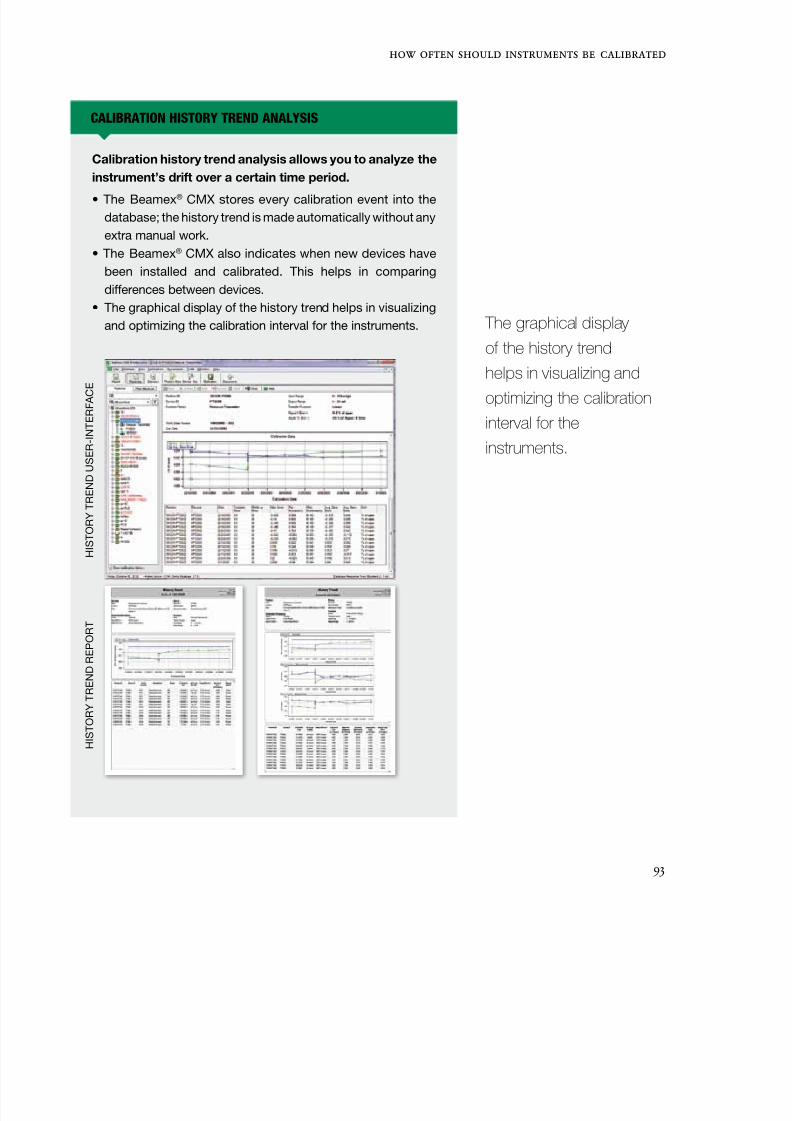
8/20/2019 Beamex Book Ultimate Calibration
http://slidepdf.com/reader/full/beamex-book-ultimate-calibration 93/204
93
Calibration history trend analysis allows you to analyze the
instrument’s drift over a certain time period.
• The Beamex® CMX stores every calibration event into the
database; the history trend is made automatically without any
extra manual work.
• The Beamex® CMX also indicates when new devices have
been installed and calibrated. This helps in comparing
differences between devices.
• The graphical display of the history trend helps in visualizing
and optimizing the calibration interval for the instruments.
CALIBRATION HISTORY TREND ANALYSIS
H I S T O R Y T R E N D
U S E R - I N T E R F A C
E
H I S T O R Y T R E N D
R E P O R T
The graphical display
of the history trend
helps in visualizing and
optimizing the calibration
interval for the
instruments.
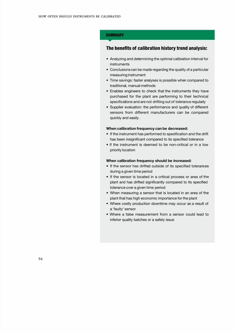
8/20/2019 Beamex Book Ultimate Calibration
http://slidepdf.com/reader/full/beamex-book-ultimate-calibration 94/204
94
SUMMARY
The benefits of calibration history trend analysis:
• Analyzing and determining the optimal calibration interval for
instruments
• Conclusions can be made regarding the quality of a particular
measuring instrument
• Time savings: faster analyses is possible when compared to
traditional, manual methods
• Enables engineers to check that the instruments they have
purchased for the plant are performing to their technical
specifications and are not drifting out of tolerance regularly
• Supplier evaluation: the performance and quality of different
sensors from different manufacturers can be compared
quickly and easily.
When calibration frequency can be decreased:
• If the instrument has performed to specification and the drift
has been insignificant compared to its specified tolerance
• If the instrument is deemed to be non-critical or in a low
priority location
When calibration frequency should be increased:
• If the sensor has drifted outside of its specified tolerances
during a given time period
• If the sensor is located in a critical process or area of the
plant and has drifted significantly compared to its specified
tolerance over a given time period
• When measuring a sensor that is located in an area of the
plant that has high economic importance for the plant
• Where costly production downtime may occur as a result of
a ‘faulty’ sensor
• Where a false measurement from a sensor could lead to
inferior quality batches or a safety issue

8/20/2019 Beamex Book Ultimate Calibration
http://slidepdf.com/reader/full/beamex-book-ultimate-calibration 95/204
95
ISO 9001:2008 quality management requirements

8/20/2019 Beamex Book Ultimate Calibration
http://slidepdf.com/reader/full/beamex-book-ultimate-calibration 96/204
8/20/2019 Beamex Book Ultimate Calibration
http://slidepdf.com/reader/full/beamex-book-ultimate-calibration 97/204
97
As a general rule for Beamex’s documenting MC calibrators,
starting with a 1-year calibration period is recommended,
because the calibrators has a 1-year uncertainty specified.The calibration period can be changed in the future, once you
begin receiving cumulated stability history, which is then compared
to the uncertainty requirements. In any case, there are many issues
to be considered when deciding a calibrator’s calibration period, or
the calibration period for any type of measuring device. This article
discusses some of the things to be considered when determining the
calibration period, and provides some general guidelines for making
this decision. The guidelines that apply to a calibrator, also apply to
other measuring equipment in the traceability chain. These guidelines
can also be used for process instrumentation.
An important aspect to consider when maintaining a traceable
calibration system is to determine how often the calibration equipment
should be recalibrated. International standards (such as ISO9000,
ISO10012, ISO17025, CFRs by FDA, GMP, etc.) require the use
of documented calibration programs. This means that measuring
equipment should be calibrated traceably at appropriate intervals and
that the basis for the calibration intervals should be evaluated and
documented.
When determining an appropriate calibration period for any
measuring equipment, there are several things to be considered. They
are discussed below.
How often should
calibrators be calibrated
Uncertainty need is
one of the most importantthings to consider when
determining the calibration
period.

8/20/2019 Beamex Book Ultimate Calibration
http://slidepdf.com/reader/full/beamex-book-ultimate-calibration 98/204
98
Uncertainty need
One of the first things to evaluate is the uncertainty need of th
customer for their particular measurement device. Actually, the initi
selection of the measurement device should be also done based on th
evaluation. Uncertainty need is one of the most important things tconsider when determining the calibration period.
Stability history
When the customer has evaluated his/her needs and purchased suitabl
measuring equipment, (s)he should monitor the stability history of th
measuring equipment. The stability history is important criteria whe
deciding upon any changes in the calibration period. Comparing th
stability history of measuring equipment to the specified limits an
uncertainty needs provides a feasible tool for evaluating the calibratio
period. Naturally, calibration management software with the historanalysis option is a great help in making this type of analysis.
The cost of recalibration vs. consequences
of an out-of-tolerance situation
Optimizing between recalibration costs and the consequences of an ou
of-tolerance situation is important. In critical applications, the costs o
an out-of-tolerance situation can be extremely high (e.g. pharmaceutic
applications) and therefore calibrating the equipment more often
safer. However, in some non-critical applications, where the out-o
tolerance consequences are not serious, calibration can be made les
frequently. Therefore, evaluating of the consequences of an out-o
tolerance situation is something to be considered. The corrective action
in such a case should also be made into an operating procedure.
Some measurements in a factory typically have more effect on
product quality than others, and therefore some measurements ar
more acute than others and should be also calibrated more often tha
others.
Initial calibration period
When you purchase calibration equipment with which you are no
familiar, you still need to decide the initial calibration period. In th
In critical applications,
the costs of an out-
of-tolerance situation
can be extremely high
(e.g. pharmaceuticalapplications) and therefore
calibrating the equipment
more often is safer.

8/20/2019 Beamex Book Ultimate Calibration
http://slidepdf.com/reader/full/beamex-book-ultimate-calibration 99/204
99
situation, abiding by the manufacturer’s recommendation is best. For
more acute applications, using a shorter calibration period right from
the beginning is recommended.
Other things to be consideredThere are also other issues to be considered when determining
the calibration period, such as the workload of the equipment,
the conditions where the equipment will be used, the amount of
transportation and is the equipment look damaged.
In some cases, crosschecking with other similar measuring
equipment is also feasible for detecting the need for calibration.
Crosschecking may be carried out before every measurement in some
acute applications.
Naturally, only appropriate, metrological, responsible personnel
in the company may make changes to the calibration equipment’s
calibration period.
In some cases,
crosschecking with
other similar measuring
equipment is also feasible
for detecting the needfor calibration.
SUMMARY
The main issues to be considered when determining the
calibration period for measuring equipment should include at
least following:
• The uncertainty needs of the measurements
to be done.
• The stability history of the measuring equipment.
• Equipment manufacturer’s recommendations.
• The risk and consequences of an out-of-tolerance situation.
• Acuteness of the measurements.

8/20/2019 Beamex Book Ultimate Calibration
http://slidepdf.com/reader/full/beamex-book-ultimate-calibration 100/204

8/20/2019 Beamex Book Ultimate Calibration
http://slidepdf.com/reader/full/beamex-book-ultimate-calibration 101/204
101
Paper is part of our everyday lives – whether in the workplace or
at home. Take a minute to look around the room you are in and
you’ll notice how many objects are made from paper: books,
magazines, printer paper, perhaps even a poster on the wall.
Global consumption of paper has grown 400% in the last 40 years.Today, almost 4 billion trees or 35% of the total trees cut down across
the world are used in paper industries on every continent (source: www.
ecology.com).
So let’s not add to this already heavy burden on our forests and
the environment. As manufacturing companies, our consumption of
paper is far higher than it needs to be, especially given that there are
technologies, software and electronic devices readily available today
which render the use of paper in the workplace unnecessary.
Other than helping to save our planet and reducing the number of
trees cut down each year, as businesses, there are other, significant
benefits in minimising the use of paper.
Take the calibration of plant instrumentation devices such as
temperature sensors, weighing instruments and pressure transducers.
Globally, amongst the process manufacturing industries, calibrating
instruments is an enormous task that consumes vast amounts of
paperwork. Far too many of these companies still use paper-based
calibration systems, which means they are missing out on the benefits
of moving towards a paperless calibration system.
Traditional paper-based calibration systems
Typically, a paper-based calibration system involves the use of hand-
written documents. Whilst out in the field, a maintenance or service
Paperless calibration improves
quality and cuts costs
Far too many of these
companies still use
paper-based calibration
systems, which means
they are missing out on
the benefits of moving
towards a paperless
calibration system.

8/20/2019 Beamex Book Ultimate Calibration
http://slidepdf.com/reader/full/beamex-book-ultimate-calibration 102/204
102
engineer will typically use a pen and paper to record instrumen
calibration results. On returning to the office, these notes are the
tidied up and/or transferred to another paper document, after whic
they are archived as paper documents.
While using a manual, paper-based system requires little or n
investment in new technology or IT systems, it is extremely labouintensive and means that historical trend analysis of calibration resul
becomes very diff icult. In addition, accessing calibration data quickl
is not easy. Paper systems are time consuming, they soak up lots o
company resources and manual (typing) errors are commonplace. Du
effort and the re-keying of calibration data into multiple database
become significant costs to the business.
These same companies that use paper-based calibration system
are together generating hundreds of thousands (millions?) of pape
calibration certificates each year. However, by utilising the lates
software-based calibration management systems from companie
like Beamex, these organisations can signif icantly reduce their papconsumption, whilst also improving quality, workflow and makin
other significant cost savings for the business.
Practical benefits of using less paper
Aside from the financial benefits of moving towards a paperles
calibration system, there are practical reasons why firms should g
paperless. Often, in industrial environments, it is not practicable t
store or carry lots of paperwork. After all, every square foot of th
business has an associated cost.
Furthermore, important paper records could potentially be lo
or damaged in an accident or fire. So why would these companie
generate and store separate paper copies of important records such a
works orders, standard operating procedures (SOPs), blank calibratio
certificates, etc. when these records can all be combined into a sing
electronic record?
Improved workflow
With paper-based systems, paper records that need approval have to b
routed to several individuals, which is time-consuming. With paperles
systems, workflow improves dramatically. There will be less waitin
time, as those individuals who need to sign off records or calibratio
With paperless
systems, workflow
improves dramatically.
8/20/2019 Beamex Book Ultimate Calibration
http://slidepdf.com/reader/full/beamex-book-ultimate-calibration 103/204
103
Paperless calibration
systems improve plant
efficiencies because the
entire calibration process
is now streamlined and
automated.
documents can share or access electronic records simultaneously from
a central database. The cost and time associated with printing copies
of paper documents is also eliminated, as well as the cost of filing and
storing those paper records.
Just as important, electronic records enable easier analysis of data,
particularly calibration results. Historical trending becomes easier,faster and more reliable, which again has cost reduction benefits to the
business. Calibration intervals can be optimised. For example, those
instruments that are performing better than expected may well justify
a reduction in their calibration frequency.
When a plant is being audited, calibration software facilitates both
the preparation and the audit itself. Locating records and verifying
that the system works becomes effortless when compared to traditional
paper-based record keeping. Paperless calibration systems improve
plant efficiencies because the entire calibration process is now
streamlined and automated. Costly production downtime due to
unforeseen instrument failures will also be reduced.
Data integrity
The integrity of paper-based calibration systems cannot be relied
upon. Paper records may not always reflect the truth. For example,
manual errors such as misreadings can occur, particularly when using
weighscales or other instruments that are open to an individual’s
own interpretation of the data. Sometimes users may inappropriately
modify the results data due to work pressures or lack of time/resources.
Illegible handwritten notes are also a problem, especially if these
paper records need to be typed or transcribed to a computer system
or database. Transcription errors such as these can lead to all sorts of
problems for a business and can take months to rectify or to identify
the rogue data.
Business benefits
For those more enlightened companies that use software-based
calibration systems, the business benefits are signif icant. The whole
calibration process – from initial recording of calibration data through
to historical trend analysis – will take less time, whilst mistakes and
manual errors will be virtually eliminated. In turn, this means that
operators, engineers and management will have more confidence in

8/20/2019 Beamex Book Ultimate Calibration
http://slidepdf.com/reader/full/beamex-book-ultimate-calibration 104/204
104
the data, particularly when it comes to plant audits. In addition, th
greater confidence in calibration data leads to a better understandin
and analysis of business performance and KPIs (particularly if th
calibration software is integrated with other business IT systems suc
as a CMMS) leading to improved processes, increased efficiencies an
reduced plant downtime.
Commissioning
At plant commissioning times, electronic records simplif
the handover of plant and equipment. Although handover b
commissioning teams that use paper records is straightforward an
of universal format, electronic records are easy to manipulate and ca
be re-used in different IT systems. Electronic data also provides a
excellent foundation for ongoing plant operation and maintenance
without needing to collect all the plant data again.
How paperless should you go?
Of course, in reality, many companies are neither completely paperle
nor rely solely on paper-based systems – the process is sometime
a hybrid of the two. A key part of paperless calibration records i
the capture of data at point of work, often in difficult industria
environments that would make the use of portable off ice compute
impractical, and the manual entry of calibration results into un
intelligent calibration forms on portable industrial computers pron
to eye-to-hand data mis-reads and repetitive strain induced error. On
way to overcome these error prone data capture methods is to us
portable documenting calibrators to measure what can be measure
and provide intelligent, technician friendly interfaces on industrialize
PDA or tablet based hardware when manual data entry cannot b
avoided. The un-editable electronic data stored on high performanc
multifunction calibrators can be uploaded to calibration managemen
software for safe storage and asset management. Companies can g
even further than this and use electronic records for works order
business management systems, data historians, and for contro
systems. In other words, the calibration data is shared with othe
business IT systems electronically, resulting in completely paperles
end-to-end workf lows.
The calibration data
is shared with other
business IT systems
electronically, resulting
in completely paperless,
end-to-end workflows.

8/20/2019 Beamex Book Ultimate Calibration
http://slidepdf.com/reader/full/beamex-book-ultimate-calibration 105/204
105
Suitable hardware
Rather than rely on engineers in the field accurately keying in
calibration results into suitably robust laptops or PDAs, it is better to
source the data electronically using documenting calibrators that are
specifically designed for this task.
Validation, training & education
Paperless systems also need validating in the user’s own environment.
Here, Beamex provides comprehensive validation, education and
training services for customers.
Education and training for users is critical, as this will help companies
to overcome the natural resistance to change amongst the workforce,
which may be used to dealing with traditional, paper-based systems.
Case study
Beamex is helping many organisations to implement paperless
calibration management systems, including Pharmaceuticals,
Chemicals, Power & Energy, Oil Gas & Petrochemicals companies.
Amongst these customers is UK firm Croda Chemicals Europe.
Based in East Yorkshire near Goole, the Croda plant uses pressurised
vessels to purify lanolin for healthcare and beauty products. Each
vessel needs to be certified at least once every two years in order
to demonstrate that the vessel is safe and structurally sound. This
includes a functionality check on all of the pressure instrumentation,
as well as the sensors that monitor the incoming chemical additives
and the outgoing effluent.
Senior Instrument Technician David Wright recalls what it was like
to perform all of those calibration operations with paper and pencil
during the company’s regularly scheduled maintenance shutdowns:
“It took us one week to perform the calibrations and a month to put
together the necessary paperwork.”
Today, Croda uses the CMX calibration management software
system from Beamex, which coordinates data collection tasks and
archives the results. “It’s faster, easier and more accurate than our old
paper-based procedures,” says Wright. “It’s saving us around 80 man-
hours per maintenance period and should pay for itself in less than
three years.”
Education and training
for users is critical, as
this will help companies
to overcome the natural
resistance to change
amongst the workforce,
which may be used to
dealing with traditional,
paper-based systems.

8/20/2019 Beamex Book Ultimate Calibration
http://slidepdf.com/reader/full/beamex-book-ultimate-calibration 106/204
106

8/20/2019 Beamex Book Ultimate Calibration
http://slidepdf.com/reader/full/beamex-book-ultimate-calibration 107/204
107
Calibration plays a vital role in process plant commissioning and
when installing new instruments. This article explains process
instrument commissioning and the benefits of calibration
during the commissioning phase.
What is process instrument commissioning?
Successful commissioning of process instrumentation is an essential
requirement for ideal plant performance. A plant, or any defined part
of a plant, is ready for commissioning when the plant has achieved
mechanical completion. Plant commissioning involves activities such
as checking to ensure plant construction is complete and complies with
the documented design or acceptable (authorized and recorded) design
changes. In general, commissioning activities are those associated with
preparing or operating the plant or any part of the plant prior to the
initial start-up and are frequently undertaken by the owner or joint
owner/ contractor team.
Commissioning may involve mock operations which are
commissioning activities conducted to allow operational testing
of the equipment and operator training and familiarization. At
the completion of commissioning, the plant will be fully ready for
production operation.
Energizing power systems, operational testing of plant equipment,
calibration of instrumentation, testing of the control systems as well as
verification of the operation of all interlocks and other safety systems
are also typical commissioning tasks. These activities are usually
described as ‘cold commissioning’.
Pre-commissioning activities are those which have to be undertaken
Intelligent commissioning
Successful commissioning
of process instrumentation
must be considered within
the context of the overall
commissioning program.

8/20/2019 Beamex Book Ultimate Calibration
http://slidepdf.com/reader/full/beamex-book-ultimate-calibration 108/204
108
prior to operating equipment, such as adjustments and check
on machinery performed by the construction contractor prior t
commissioning and without which the installation cannot be said t
be mechanically complete. Mechanical completion of a plant or an
part of a plant occurs when the plant or a part of the plant has bee
completed in accordance with the drawings and specifications, and thre-commissioning activities have been completed to the extent wher
the owner approves the plant and can begin commissioning activitie
Commissioning requires a team of people with a background i
plant design, plant operation and plant maintenance. Some companie
employ specialized commissioning engineers. This can prove to be
worthwhile investment for large plants because it allows for dedicate
responsibility and focus in operations and signif icant improvements t
schedules, and adverse incidents at the start-up phase can be avoided
An extra day taken for commissioning means the same to the plan
owner as an extra day taken during designing or construction; in fact,
may cost more, as the plant owner’s commitments in terms of producmarketing and operational costs are likely to be higher.
Management, personnel and cost of commissioning
Since commissioning takes place toward the end of the project, ther
is a risk that the work may be under-resourced, because the funds hav
been allotted to cover budget overruns. It is essential to comprehen
the scope and length of commissioning activities and include them
in the initial project plan and budget allocations, and ensure th
commitment is maintained.
The cost of process instrument commissioning is typically affecte
by the following issues: learning and familiarizing with the field devic
physically installing the field device, connecting to and identifyin
the field device, configuring the required parameters and testing th
configuration and interface to other systems. Basically, these steps mu
be repeated with every field device that will be installed at the plant.
As there are many cost factors in the commissioning proces
detailed planning of commissioning and plant handover are essentia
elements of the overall project plan and schedule as any other groupin
of activities.
Each of the commissioning activities must be broken down into
number of manageable tasks, and a schedule needs to be establishe
for each task including benchmarks for monitoring purposes. The rat
There are many reasons
why instruments should
be calibrated during the
commissioning phase
before start-up.

8/20/2019 Beamex Book Ultimate Calibration
http://slidepdf.com/reader/full/beamex-book-ultimate-calibration 109/204
109
of commissioning is measurable (e.g. number of loops or sequence
of steps tested per day), thereby enabling progress to be reviewed
regularly.
Successful commissioning of process instrumentation must be
considered within the context of the overall commissioning program.
Good planning, coordination, communications, documentation,
teamwork and training are all essential. The commissioning team
consists of a mixture of specialists, instrument and process engineers,
and the size of the team and composition of specialists depends on
the nature and scope of the system.
Calibration and the commissioning of field instrumentation
New process instrumentation is typically configured and calibrated by
the manufacturer prior to installation. However, instruments are often
recalibrated upon arrival at the site, especially if there has been obvious
Sequence of activities leading to commissioning and acceptance of a
plant.
Construction
Pre-commissioning
Mechanical completion
Commissioning
Trial operation
Initial start-up
Examine product specification
Examine production performance
Acceptance of plant
The calibration database
can be calibration
software designed
specifically for managing
calibration assets and
information, such as the
Beamex ® CMX Calibration
Software.

8/20/2019 Beamex Book Ultimate Calibration
http://slidepdf.com/reader/full/beamex-book-ultimate-calibration 110/204
110
damage in transit or storage. There are also many other reasons wh
instruments should be calibrated during the commissioning phas
before start-up.
Assuring transmitter quality
First of all, the fact that an instrument or transmitter is new doenot automatically mean that it is within required specification
Calibrating a new instrument before installing or using it is a qualit
assurance task. You can check the overall quality of the instrument t
see if it is defective and to ensure it has the correct, specif ied setting
Reconfiguring a transmitter
The new uninstalled instrument or transmitter may have the correc
specified settings. However, it is possible that the original planne
settings are not valid anymore and they need to be changed. B
calibrating an instrument you can check the settings of the instrumen
After you have performed this task, it is possible to reconfigurthe transmitter, when the initial planned specifications have bee
changed. Calibration is therefore a key element in the process o
reconfiguring an uninstalled transmitter.
Monitoring the quality and stability of a transmitter
When calibration procedures are performed for an uninstalle
instrument, the calibration serves also future purposes. By calibratin
the transmitter before installation and on a regular basis thereafter,
is possible to monitor the stability of the transmitter.
Entering the necessary transmitter data into a calibration database
By calibrating an instrument before installation it is possible t
enter all the necessary instrument data into the calibration databas
as well as to monitor the instrument’s stability, as was explained i
the previous paragraph. The calibration database can be calibratio
software designed specifically for managing calibration assets an
information, such as the Beamex® CMX Calibration Software. Th
transmitter information is critical in defining the quality of th
instrument and for planning the optimal calibration interval of th
instrument. Transmitters that are found to be highly stable nee
not be recalibrated as often as transmitters that tend to drift. Th
trick is determining which sensors should be recalibrated after a few
hours, weeks, or years of operation and which can be left as is fo
The trick is determining
which sensors should be
recalibrated after a few
hours, weeks, or years
of operation and which
can be left as is for longer
periods without sacrificing
quality or safety.

8/20/2019 Beamex Book Ultimate Calibration
http://slidepdf.com/reader/full/beamex-book-ultimate-calibration 111/204
111
longer periods without sacrificing quality or safety. Doing so allows
maintenance personnel to concentrate their efforts only where needed,
thereby eliminating unnecessary calibration work. Therefore, entering
the instrument data into a calibration management system is part of
the calibration procedures performed on an instrument before it is
installed and in use.
Integrated calibration solution by Beamex
The Beamex® Integrated Calibration Solution, consisting of calibration
software and documenting calibration equipment, improves the
quality and efficiency of the entire calibration system through faster,
smarter and more accurate management of all calibration assets and
procedures.
The Beamex® MC series documenting calibrators can be used for
calibrating pressure, temperature, electrical and frequency signals. The
Beamex calibrators support various different transmitter protocols,such as analog, HART, Foundation Fieldbus and Profibus. The Beamex
calibrators are all-in-one calibrators, which mean that they can be used
to replace several individual measurement devices. Intrinsically safe
calibrators for potentially explosive environments are also available.
The Beamex® CMX Calibration Software can be used for improving
the quality, productivity and cost-effectiveness of a plant’s calibration
process. The Beamex® CMX can be used for planning and scheduling
calibrations, managing and storing all calibration data as well as
analyzing and optimizing the calibration interval. Using the CMX
gives always a clear status of the transmitters; for instance, are they
installed and ready for calibration, does anyone perform the calibration
(check in/out function) and what is the instrument/position status
(pass/fail).
Having a fully integrated calibration management system – using
documenting calibrators and calibration management software
– is important. Beamex® CMX Calibration Software ensures
that calibration procedures are carried out at the correct time and
that calibration tasks do not get forgotten, overlooked or become
overdue. By using a documenting calibrator, the calibration results
are stored automatically in the calibrator’s memory during the
calibration process. Engineers performing calibrations no longer
have to write down any results on paper, making the entire process
much quicker and reducing costs. All calibration documentation is
Beamex ® CMX Calibration
Software ensures that
calibration procedures are
carried out at the correct
time and that calibration
tasks do not get forgotten,
overlooked or become
overdue.

8/20/2019 Beamex Book Ultimate Calibration
http://slidepdf.com/reader/full/beamex-book-ultimate-calibration 112/204
112
therefore automatically produced when using the Beamex® Integrate
Calibration Solution. The quality and accuracy of calibration resul
also improve, as there are fewer mistakes due to human error. Th
calibration results are transferred automatically from the calibrator
memory to the computer/ database. This means that engineers do no
spend their time transferring the results from their notepad to finastorage on a computer; again, saving time and money.
Major time-savings can also be achieved by using Beamex
documenting MC calibrators HART and/or Fieldbus functionalit
to enter transmitter data into the calibrators’ memory where the dat
can be populated to the CMX Calibration Software, instead of typin
the data manually into the calibration database.
SUMMARY
Calibration is beneficial during process plant commissioning
for various different reasons:
• Transmitter quality assurance
• Reconfiguring a transmitter
• Monitoring the quality and stability of a transmitter
• Entering the necessary transmitter data into a calibration
database and defining the optimal calibration interval
By using a documenting
calibrator, the calibration
results are stored
automatically in the
calibrator’s memory
during the calibration
process.

8/20/2019 Beamex Book Ultimate Calibration
http://slidepdf.com/reader/full/beamex-book-ultimate-calibration 113/204
113

8/20/2019 Beamex Book Ultimate Calibration
http://slidepdf.com/reader/full/beamex-book-ultimate-calibration 114/204
114

8/20/2019 Beamex Book Ultimate Calibration
http://slidepdf.com/reader/full/beamex-book-ultimate-calibration 115/204
115
For process manufacturers today, having a reliable, seamlessly
integrated set of IT systems across the plant, or across multiple
sites, is critical to business efficiency, profitability and growth.
Maintaining plant assets – whether that includes production line
equipment, boilers, furnaces, special purpose machines, conveyorsystems or hydraulic pumps – is equally critical for these companies.
Maintenance management has become an issue which deserves
enterprise-wide and perhaps multi-site attention, especially if the
company is part of an asset-intensive industry, where equipment and
plant infrastructure is large, complex and expensive. If stoppages
to production lines due to equipment breakdowns are costly,
implementing the latest computerized maintenance management
systems (CMMS) might save precious time and money.
In the process industries, a small, but critical part of a company’s
asset management strategy should be the calibration of process
instrumentation. Manufacturing plants need to be sure that their
instrumentation products – temperature sensors, pressure transducers,
flow meters and the like – are performing and measuring to specified
tolerances. If sensors drift out of their specification range, the
consequences can be disastrous, perhaps resulting in costly production
downtime, safety issues or batches of inferior quality goods being
produced, which then have to be scrapped. For this, Beamex’s
calibration management software, Beamex® CMX, has proved
itself time and time again across many industry sectors, including
pharmaceuticals, chemicals, nuclear, metal processing, paper, oil and
gas.
Successfully executing a system
integration project
In the process industries,
a small, but critical
part of a company’s
asset management
strategy should be the
calibration of process
instrumentation.

8/20/2019 Beamex Book Ultimate Calibration
http://slidepdf.com/reader/full/beamex-book-ultimate-calibration 116/204
116
Seamless communication
Today, most process manufacturers use some sort of computerize
maintenance management system (CMMS) that sits alongsid
their calibration management system. Beamex® CMX Professiona
or Beamex® CMX Enterprise software can easily be integrated tCMM systems, whether it is a Maximo, SAP or Datastream CMM
system or even a company’s own, in-house software for maintenanc
management.
Beamex® CMX helps companies document, schedule, plan, analyz
and optimize their calibration work. Seamless communication betwee
CMX and ‘smart’ calibrators means that companies have the ability t
automate predefined calibration procedures. As well as retrieving an
storing calibration data, CMX can also download detailed instruction
for operation before and after calibrating, like procedures, reminde
and safety-related information. Seamless communication wit
calibrators also provides many practical benefits such as a reductioin paperwork, elimination of human error associated with manua
recording, and the ability to speed up the calibration task. CMX als
stores the complete calibration history of process instruments an
produces fully traceable calibration records.
Integrating CMX with a CMM system means that plant hierarch
and all work orders for process instruments can be generated an
maintained in the customer’s CMM system. Calibration wor
orders can easily be transferred to CMX Calibration Software. Then
once the calibration work order has been executed, CMX sends a
acknowledgement order of this work back to the customer’s CMM
system. All detailed calibration results are stored and available on th
CMX database.
Integration project
A customer may have a large CMM system and a considerable amoun
of data keying to perform before integration is complete. A dat
exchange module or interface that sits between the two systems i
required. The integration project involves three main parties: Beamex
the customer and the CMM system software partner.
Beamex ® CMX
Professional or Beamex ®
CMX Enterprise software
can easily be integrated
to CMM systems,
whether it is a Maximo,
SAP or Datastream
CMM system or even a
company’s own, in-house
software for maintenance
management.

8/20/2019 Beamex Book Ultimate Calibration
http://slidepdf.com/reader/full/beamex-book-ultimate-calibration 117/204
117
Project organization and resourcing
In order to have a successful integration, it’s important that the right
people and decision-makers are involved and participate right from
the beginning of the project. It’s also essential that the main roles and
responsibilities of the parties are specif ied before the project evolves.Moreover, a project organization should be established and include
members from both the supplier’s and the customer’s organization,
as a successful project requires input from both parties. The role of
each member should be defined and project managers appointed. The
project manager is usually responsible for the operative management
of the project. In addition, a project steering group may need to be
established. The project steering group is responsible for making key
decisions during the project. The role, tasks and authority of the
project steering group must be defined as well as the decision-making
procedures.
Project phases
The integration project is divided into four main phases:
1. Scope of Work
2. Development and Implementation
3. Testing
4. Installation, Verification and Training
The four main phases are also often divided into sub-phases. A
schedule is usually defined for the completion of the entire project as
well as for the completion of each project phase. Each project phase
should be approved according to the acceptance procedures defined
in the offer, agreement, project plan or other document annexed to
the offer / agreement.
The integration project
involves three main
parties: Beamex, the
customer and the CMM
system software partner.
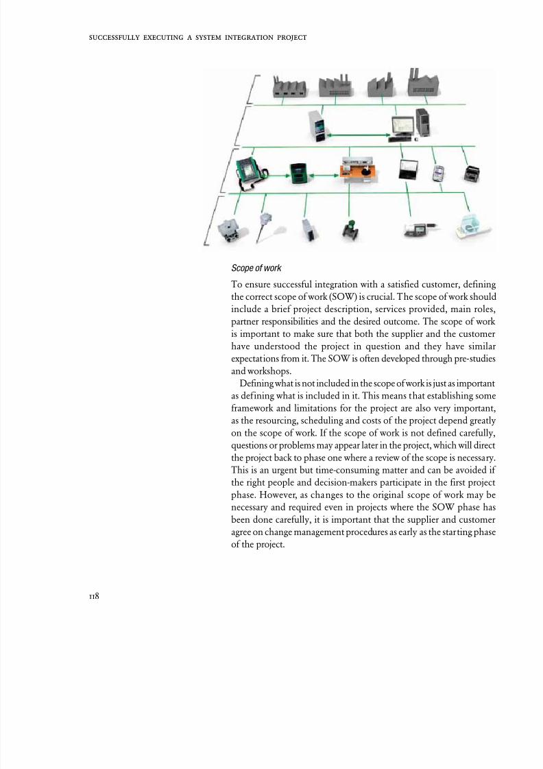
8/20/2019 Beamex Book Ultimate Calibration
http://slidepdf.com/reader/full/beamex-book-ultimate-calibration 118/204
118
Scope of work
To ensure successful integration with a satisfied customer, definin
the correct scope of work (SOW) is crucial. The scope of work shoul
include a brief project description, services provided, main role
partner responsibilities and the desired outcome. The scope of wor
is important to make sure that both the supplier and the custome
have understood the project in question and they have simila
expectations from it. The SOW is often developed through pre-studie
and workshops.
Defining what is not included in the scope of work is just as importan
as defining what is included in it. This means that establishing som
framework and limitations for the project are also very importan
as the resourcing, scheduling and costs of the project depend greatl
on the scope of work. If the scope of work is not defined carefully
questions or problems may appear later in the project, which will direc
the project back to phase one where a review of the scope is necessary
This is an urgent but time-consuming matter and can be avoided
the right people and decision-makers participate in the first projec
phase. However, as changes to the original scope of work may b
necessary and required even in projects where the SOW phase ha
been done carefully, it is important that the supplier and custome
agree on change management procedures as early as the starting phas
of the project.

8/20/2019 Beamex Book Ultimate Calibration
http://slidepdf.com/reader/full/beamex-book-ultimate-calibration 119/204
119
Development and implementation
When the scope of work has been defined and approved by both
parties, the integration can enter the next phase, which is the actual
development and implementation of the project deliverables.
Testing
Testing occurs both during the project after each partial delivery, in
order to be able to continue the development work to next phase, and
at the final stage of the project. The testing, approval procedures and
timelines should be defined when agreeing on the project.
Installation, verification and training
The final stage in the integration process is the installation and testing
at the customer’s facility and taking the system into production use.
The project manager at the buyer’s facility now plays a major role in
the success of the integration process. The supplier will, if requiredand agreed, assist with informing, training and providing training
materials.
When the integration is finished, the customer has a system that
saves time, reduces costs and increases productivity by preventing
unnecessary double effort and re-keying of procedures in separate
When the integration is
finished, the customer
has a system that saves
time, reduces costs and
increases productivity by
preventing unnecessary
double effort and re-
keying of procedures in
separate systems.INTEGRATION PROJECT PHASES
Specifications
documentation
• Purpose / needs
• Target• Supplier’s responsibilities• Customer’s responsibilities• Project management and
project steering group
• Change management
• Testing and acceptanceprocedures
• Final approval by customer
Implementationdocumentation
Testingdocumentation
Instructionaldocumentation
FOLLOW UPCLOSURE OF INTEGRATION PROJECT
Scope of
work (SOW)
Development
and
implementation
Testing
Ve n
Tr
Installation
rificatio
aining

8/20/2019 Beamex Book Ultimate Calibration
http://slidepdf.com/reader/full/beamex-book-ultimate-calibration 120/204
120
systems. When there is no need to manually re-key the data, typin
errors are eliminated. A CMMS integration will enable the custome
company to automate its’ management with smart calibrators. Th
improves the quality of the entire system.
Integrating a CMM system with calibration management softwar
is an important step in the right direction when it comes to EAMEnterprise Asset Management. However, EAM is more than ju
maintenance management software. It’s about companies taking
business-wide view of all their plant equipment and coordinatin
maintenance activities and resources with other departments an
sites, particularly with production teams. Savings from EAM ar
reasonably well-documented and come in various guises, the mo
common benefits being: less equipment breakdowns (leading to
reduction in overall plant downtime); a corresponding increase i
asset utilization or plant uptime; better management of spare par
and equipment stocks; more eff icient use of maintenance staff; an
optimized scheduling of maintenance tasks and resources. But thkey to success is really the quality of information you put in th
software, the data has to be as close to 100% accurate as possible t
get maximum benefit from the system.
Integrating a CMM
system with calibration
management software
is an important step in
the right direction when it
comes to EAM, Enterprise
Asset Management.

8/20/2019 Beamex Book Ultimate Calibration
http://slidepdf.com/reader/full/beamex-book-ultimate-calibration 121/204
121

8/20/2019 Beamex Book Ultimate Calibration
http://slidepdf.com/reader/full/beamex-book-ultimate-calibration 122/204

8/20/2019 Beamex Book Ultimate Calibration
http://slidepdf.com/reader/full/beamex-book-ultimate-calibration 123/204
Calibrationin Industrial
Applications

8/20/2019 Beamex Book Ultimate Calibration
http://slidepdf.com/reader/full/beamex-book-ultimate-calibration 124/204
124

8/20/2019 Beamex Book Ultimate Calibration
http://slidepdf.com/reader/full/beamex-book-ultimate-calibration 125/204
125
F
or process manufacturers, regular calibration of instruments
throughout a manufacturing plant is common practice. In plant
areas where instrument accuracy is critical to ensure product
quality, safety or custody transfer, calibration every six months – oreven more frequently – is not unusual.
However, the key final step in any calibration process – documentation
– is often neglected or overlooked because of a lack of resources, time
constraints or the pressure of everyday activities. Indeed, many process
plants are under pressure to calibrate instruments quickly but accurately
and to ensure that the results are then documented for quality assurance
purposes and to provide full traceability.
The purpose of calibration itself is to determine how accurate an
instrument or sensor is. Although most instruments are very accurate
these days, regulatory bodies often need to know just how inaccurate a
particular instrument is and whether it drifts in and out of a specified
tolerance over time.
What is a documenting calibrator?
A documenting calibrator is a handheld electronic communication
device that is capable of calibrating many different process signals
such as pressure, temperature and electrical signals, including
frequency and pulses, and then automatically documenting the
calibration results by transferring them to a fully integrated calibration
management software. Some calibrators can read HART, Foundation
Fieldbus or Profibus output of the transmitters and can even be used
for configuring ‘smart’ sensors.
The benefits of usinga documenting calibrator
Many process plants
are under pressure to
calibrate instrumentsquickly but accurately and
to ensure that the results
are then documented
for quality assurance
purposes and to provide
full traceability.
8/20/2019 Beamex Book Ultimate Calibration
http://slidepdf.com/reader/full/beamex-book-ultimate-calibration 126/204
126
Heikki Laurila, Product Manager at Beamex in Finland comment
“I would define a documenting calibrator as a device that has the dua
functionality of being able to save and store calibration results in i
memory, but which also integrates and automatically transfers thi
information to some sort of calibration management software.”
A non-documenting calibrator is a device that does not store dator stores calibration data from instruments but is not integrated to
calibration management system. Calibration results have to be keye
manually into a separate database, spreadsheet or paper filling system
Why use a documenting calibrator?
By using a documenting calibrator, the calibration results are store
automatically in the calibrator’s memory during the calibratio
process. The engineer does not have to write any results down o
paper, which makes the entire process much faster and consequentl
reduces costs. The quality and accuracy of calibration results will alsimprove, as there will be fewer mistakes due to human error.
The calibration results are automatically transferred from th
calibrator’s memory to the computer/database. This means th
engineer does not have to spend time transferring the results from h
notepad to final storage on a computer; again, saving time and mone
With instrument calibration, the calibration procedure itself
critical. Performing the calibration procedure in the same way eac
time is important for the consistency of results. With a documentin
calibrator, the calibration procedure can be automatically transferre
from the computer to the handheld calibrator before going out int
the field.
As Laurila states, “Engineers, who are out in the field performin
instrument calibrations, receive instant pass or fail messages with
documenting calibrator. The tolerances and limits for a sensor, a
well as detailed instructions on how to calibrate the transmitter, ar
entered once into the calibration management software and the
downloaded to the calibrator. This means calibrations are carried ou
in the same way every time because the calibrator tells the enginee
which test point he needs to measure next. Also, having an easy-to
use documenting calibrator is definitely the way forward, especiall
if calibration is one of the many tasks that the user has to carry out i
his daily maintenance routine.”
With a multi-functioning documenting calibrator, such as th
The engineer does
not have to write any
results down on paper,
which makes the entire
process much faster and
consequently reduces
costs.

8/20/2019 Beamex Book Ultimate Calibration
http://slidepdf.com/reader/full/beamex-book-ultimate-calibration 127/204
127
Beamex® MC5 or MC6, the user doesn’t need to carry as much
equipment while out in the field. Both calibrators can be used also
to calibrate, configure and trim HART, Foundation Fieldbus H1 or
Profibus PA transmitters.
Laurila continues, “With a documenting calibrator, such as the
MC5 or the MC6, the user can download calibration instructions forhundreds of different instruments into the device’s memory before
going out into the field. The corresponding calibration results for
these instruments can be saved in the device without the user having
to return to his PC in the off ice to download/upload data. This means
the user can work in the f ield for several days.”
Having a fully integrated calibration management system – using
documenting calibrators and calibration management software –
is important. Beamex® CMX Calibration Software ensures that
calibration procedures are carried out at the correct time and that
calibration tasks are not forgotten, overlooked or overdue.
Benefits in practice
Conventional calibration work relies on manual, paper-based
systems for documenting. Manual calibration takes more time and
is more prone to error. Oftentimes, the f ield engineer calibrates the
instrument, handwrites the results onto a paper form and then re-
enters this information into a database when he returns to the office.
Unintentional errors often occur and the whole process is time-
consuming.
Using Beamex® CMX Calibration Software and the documenting
Beamex® MC6 or MC5 Multifunction Calibrators provides full
control of the entire calibration process and reduces costs by up
to 50 %.* Why? Because the devices provide higher accuracy, the
calibration process is much faster, and the system provides full
traceability. When you’ve got to calibrate instruments throughout a
site, typically with five-point checks on each instrument, speed and
accuracy are critical. Using the MC6 or MC5 with CMX software
means that calibration instructions for an instrument and calibration
orders are downloaded to the calibrators and ready to guide the
engineer in the field with correct calibration procedures.
Calibration software
ensures that calibration
procedures are carried out
at the correct time and that
calibration tasks are not
forgotten, overlooked or
overdue.
___________________* Reported to the Industrial Instrumentation and Controls Technology Alliance and presented
at the TAMU ISA Symposium, January, 2004

8/20/2019 Beamex Book Ultimate Calibration
http://slidepdf.com/reader/full/beamex-book-ultimate-calibration 128/204
128
After completing instrument calibrations, the system provides
full quality assurance report of all instruments calibrated along with
required calibration certif icate. This not only ensures full traceabilit
but also ref lects full and traceable documentation of the complete
work.
Calibration results are
automatically transferred
from the calibrator’s
memory to a computer or
fully integrated calibration
management system.
SUMMARY
The benefits of using a documenting calibrator
• Calibration results are automatically stored in the
calibrator’s on-board memory during the calibration
procedure.
• Calibration results are automatically transferred from the
calibrator’s memory to a computer or fully integrated
calibration management system.
• Less paperwork and fewer manual errors.
• Reduced costs from a faster and more efficient calibration
process.
• Improved accuracy, consistency and quality of calibration
results.
• A fully traceable calibration system for the entire plant.
• The calibration procedure itself is guided by the calibrator,
which uploads detailed instructions from the computer or
calibration management software.
• No manual printing or reading of calibration instructions is
required; again, saving time and money and simplifying the
process.

8/20/2019 Beamex Book Ultimate Calibration
http://slidepdf.com/reader/full/beamex-book-ultimate-calibration 129/204
129

8/20/2019 Beamex Book Ultimate Calibration
http://slidepdf.com/reader/full/beamex-book-ultimate-calibration 130/204

8/20/2019 Beamex Book Ultimate Calibration
http://slidepdf.com/reader/full/beamex-book-ultimate-calibration 131/204
131
From the point of view of the owner, weighing instruments, usually
called scales or balances, should provide the correct weighing
results. How the weighing instrument is used and how reliable the
weighing results are can be very different. Using weighing instruments
for legal purposes must have legal verification. If a weighing instrument is used in a quality system, the user must
define the measurement capability of it. In any case, it is the owner
or the user of the instrument that carries the final responsibility of
measurement capability and who is also responsible for the processes
involved. (S)He must select the weighing instrument and maintenance
procedure to be used to reach the required measurement capability.
From a regulatory point of view, the quality of a weighing instrument
is already defined in OIML regulations, at least in Europe. Calibration
is a means for the user to obtain evidence of the quality of weighing
results, and the user must have the knowledge to apply the information
achieved through calibration.
Calibration and legal verification
Weighing instruments may also possess special features. One of these
features includes making measurements for which legal verification is
required, for example when invoicing is based on the weight of a solid
material. The features may vary slightly from country to country, but
in the EU they are the same, at least at the stage when the weighing
instrument is being introduced into use.
Verification and calibration abide by a different philosophy.
Calibration depicts the deviation between indication and reference
(standard) including tolerance, whereas verification depicts the
Calibration of weighing instruments
Part 1
In any case, it is the
owner or the user of
the instrument that carries
the final responsibility
of measurement
capability and who is
also responsible for the
processes involved.

8/20/2019 Beamex Book Ultimate Calibration
http://slidepdf.com/reader/full/beamex-book-ultimate-calibration 132/204
132
maximum permissible amount of errors of the indication. This is
feasible practice for all weighing. The practical work for both method
is very similar and both methods can be used to confirm measuremen
capability, as long as legal verification is not needed. The terminolog
and practices used previously for verifying measurement capability
and for weighing technology in general, are based on these practices ocalibrating and verifying, even if it was a question of general weighin
(non-legal).
Confirmation is the collecting of information
Confirming the capability of weighing instruments should happe
by estimating the quality of the measuring device in the place wher
it will be used. In practice, this means investigating the efficiency o
the weighing instrument; this operation is known as calibration (o
verification). One calibration provides information on a temporar
basis and a series of calibrations provides time-dependent informationThe method of calibration should be selected such that it provide
sufficient information for evaluating the required measuring toleranc
The method should be precise for achieving comparable results durin
all calibrations.
Comparing the indication of weighing instruments with a se
standard gives the deviation or error. However, to be able to define th
measuring tolerance, we need more information about the weighin
instrument, such as repeatability, eccentric load, hysteresis, etc. W
must remember that the quality of the evaluation of measurin
tolerance depends on the collected information through calibration
Using a calibration program, which goes through the same steps fo
every calibration – calculates deviation and measuring tolerance, and,
necessary, produces a calibration certif icate – is the best way to achiev
reliable information to use in comparisons. This type of program
is able to store all the history of calibrated weighing instrument
including information for other measuring devices. It is also hand
for monitoring measuring systems. The most important aspect of
calibration program is that it allows the user to select the calibratio
method that corresponds to the required level of measuring toleranc
and it displays the history of calibrations and in this way provide
the user with comprehensive information concerning measurin
capability.
We must remember
that the quality of the
evaluation of measuring
tolerance depends on
the collected information
through calibration.

8/20/2019 Beamex Book Ultimate Calibration
http://slidepdf.com/reader/full/beamex-book-ultimate-calibration 133/204
133
The purpose of calibration and complete confirmation
Calibration is a process where the user is able to confirm the correct
function of the weighing instrument based on selected information.
The user must define the limits for permitted deviation from a true
value and required measuring tolerance. If these values are exceeded,an adjustment or maintenance is necessary.
Calibration itself, however, is a short-term process; the idea is that
the weighing instrument remains in good working condition until the
next calibration. For this reason, the user must determine all of the
external factors which may influence the proper functioning of the
weighing instrument. The factors in question may include the effect
of the environment where the weighing instrument is used and how
often the instrument needs to be cleaned, regular monitoring of the
zero point and the indication number with a constant mass.
Today, the function of weighing instruments, as well as many
other instruments, is based on microprocessors. They possess severalpossibilities for adjusting parameters in measuring procedures.
Calibration should be carried out using settings based on the
parameters for normal use. It is very important that the users of the
weighing instruments, as well as calibration personnel, are familiar
with these parameters and use them as protocol. Since there are several
parameters in use, it is important to always have the manual for using
the weighing instrument easily available to the user.
The content of the calibration certificate
Very often the calibration certificate is put on file as evidence of a
performed calibration to await the auditing of the quality system.
However, a quality system is usually concerned with the traceability
of measurements and the known measuring tolerance of the
measurements made. The calibration certif icate of a single measuring
device is used as a tool for evaluating the process of measuring tolerance
and for displaying the traceability of the device in question.
Performing calibrations based on the measuring tolerance is better
than doing routine measuring. Therefore, the user must evaluate
the process of measuring tolerance and compare this value with the
required measuring tolerance of the process.
Calibration itself, however,
is a short-term process;
the idea is that the
weighing instrument
remains in good working
condition until
the next calibration.

8/20/2019 Beamex Book Ultimate Calibration
http://slidepdf.com/reader/full/beamex-book-ultimate-calibration 134/204
134
SUMMARY
Calibration (or verification) is a fundamental tool for
maintaining a measuring system. It also assists the user in
obtaining the required quality of measurements in a process.
The following must be taken into consideration:
• the type of procedure to be applied in confirming measuring
tolerance
• the interpretation of information while abiding by the
calibration certificate
• changing procedures based on received information
Quality calibration methods and data handling systems offer
state-of-the-art possibilities to any company.

8/20/2019 Beamex Book Ultimate Calibration
http://slidepdf.com/reader/full/beamex-book-ultimate-calibration 135/204
135

8/20/2019 Beamex Book Ultimate Calibration
http://slidepdf.com/reader/full/beamex-book-ultimate-calibration 136/204

8/20/2019 Beamex Book Ultimate Calibration
http://slidepdf.com/reader/full/beamex-book-ultimate-calibration 137/204
137
Weighing is a common form of measurement in commerce,
industries and households. Weighing instruments are
often highly accurate, but users, i.e. their customers and/or
regulatory bodies, often need to know just how inaccurate a particular
scale may be. Originally, this information was obtained by classifyingand verifying the equipment for type approval. Subsequently, the
equipment was tested or calibrated on a regular basis.
Typical calibration procedures
Calibrating scales involves several different procedures depending
on national- and/or industry-specific guidelines or regulations, or on
the potential consequences of erroneous weighing results. One clear
and thorough guide is the EA-10/18, Guidelines on the Calibration
of Non-automatic Weighing Instruments, which was prepared by
the European Co-operation for Accreditation, and published by the
European Collaboration in Measurement and Standards (euromet).
Typical scale calibration involves weighing various standard weights
in three separate tests:
• repeatability test
• eccentricity test
• weighing test (test for errors of indication)
In the pharmaceutical industry in the United States, tests for
determining minimum weighing capability are also performed.
Repeated weighing measurements provide different indications
Usually, the object being weighed is placed on the load receptor
and the weighing result is read only once. If you weigh the object
Calibration of weighing instruments
Part 2
Weighing instruments are
often highly accurate, butusers, i.e. their customers
and/or regulatory bodies,
often need to know just
how inaccurate a particular
scale may be.

8/20/2019 Beamex Book Ultimate Calibration
http://slidepdf.com/reader/full/beamex-book-ultimate-calibration 138/204
138
repeatedly, you will notice slight, random variation in the indication
The repeatability test involves weighing an object several times t
determine the repeatability of the scale used.
Center of gravity mattersThe eccentricity test involves placing the object being weighed in th
middle of the load receptor as accurately as possible. This is sometime
diff icult due to the shape or construction of the object being weighed
Typical calibration procedures include the eccentricity test. You ca
determine how much the eccentricity of the load will affect th
indication on the scale by weighing the same weight at the corners o
the load receptor.
Test for errors in indication
The weighing test examines the error of the indication on the scale foseveral predefined loads. This enables you to correct the errors an
definitions for non-linearity and hysteresis.
If the scale’s maximum load limit is extremely large, it may b
impractical to use standard weights for calibrating the entire range
In such a case, suitable substitution mass is used instead. Substitutio
mass should also be used if the construction of the scale does not allo
the use of standard weights.
A truck scale is unsuitable for weighing letters
The purpose of the minimum weight test is to determine the minimum
weight, which can be assuredly and accurately measured using th
scale in question. This condition is met if the measurement error
less than 0.1% of the weight, with a probability of 99.73%.
Combined standard uncertainty of the error U(E)
Knowing the error of the scale indication at the point of eac
calibration is not sufficient. You must also know how certain you ca
be about the error found at each point of calibration. There are severa
sources of uncertainty of the error, e.g.:
Weighing instruments are
often highly accurate, but
users, i.e. their customers
and/or regulatory bodies,
often need to know just
how inaccurate a particular
scale may be.

8/20/2019 Beamex Book Ultimate Calibration
http://slidepdf.com/reader/full/beamex-book-ultimate-calibration 139/204
139
• The masses of the weights are only known with a certain uncertainty.
• Air convection causes extra force on the load receptor.
• Air buoyancy around the weights varies according to barometric
pressure, air temperature and humidity.
• A substitute load is used in calibrating the scale.
• Digital scale indications are rounded to the resolution in use.• Analogous scales have limited readability.
• There are random variations in the indications as can be seen in the
Repeatability Test.
• The weights are not in the exact middle of the load receptor.
The values of uncertainty determined at each point of calibration are
expressed as standard uncertainties (coverage probability: 68.27%),
which correspond to one standard deviation of a normally distributed
variable. The combined standard uncertainty of the error at a certain
point of calibration has a coverage probability of 68.27% as well.
Example: The calibration error
and its uncertainty at the
calibration point of 10 kg may
be expressed e.g. E = 2.5 g
and u(E) = ±0.7 g, which means
that the calculated error in the
indication is 2.5 g and the actual
error, with a coverage probability
of 68.27%, is between is between
1.8 g and 3.2 g.
±u(E)
68.27%
U(E) = 2u(E)95.45 %
2.5 g
3.2 g
3.9 g1.1 g
1.8 g
U(E) = 3u(E)99.73 %
0.4 g 4.6 g

8/20/2019 Beamex Book Ultimate Calibration
http://slidepdf.com/reader/full/beamex-book-ultimate-calibration 140/204
140
Expanded uncertainty in calibration U(E)
In practice, a coverage probability of 68.27% is insuff icient. Normall
it is extended to a level of 95.45% by multiplying it with the coverag
factor k = 2. If the distribution of the indicated error cannot b
considered normal, or the reliability of the standard uncertainty valuis insuff icient, then a larger value should be used for the k-factor.
If you are able to use the k = 2 coverage factor, then the error an
its extended uncertainty at the point of calibration are E = 2.5 g an
U(E) = ±1.4 g. This means that the calculated error of the indicatio
is 2.5 g and the actual error, with a coverage probability of 95.45%,
between 1.1 g and 3.9 g.
Uncertainty of a weighing result
The purpose of calibration is to determine how accurate a weighin
instrument is. As the above-mentioned case indicates, you know thaif you repeat the calibration several times, the indication of weighin
an object of 10 kilograms will be between 10.0011 kg and 10.0039 k
95.45% of the time. However, the uncertainty of the results of late
routine weighings is usually larger. Typical reasons for this are:
• Routine weighing measurements involve random loads, whil
calibration is made at certain calibration points.
• Routine weighing measurements are not repeated whereas indication
received through calibrations may be averages of repeated weighin
measurements.
• Finer resolution is often used in calibration.
• Loading/unloading cycles in calibration and routine weighing ma
be different.
• A load may be situated eccentrically in routine weighing.
• Tare balancing device may be used in routine weighing.
• The temperature, barometric pressure and relative humidity of th
air may vary.
• The adjustment of the weighing instrument may have changed.
Standard and expanded uncertainties of weighing results are calculate
using technical data of the weighing instrument, its calibration result
knowledge of its typical behaviour and knowledge of the conditions o
the location where the instrument is used. Defining the uncertaint
of weighing results is highly recommended, at least once, for a
The purpose of calibration
is to determine how
accurate a weighing
instrument is.

8/20/2019 Beamex Book Ultimate Calibration
http://slidepdf.com/reader/full/beamex-book-ultimate-calibration 141/204
141
typical applications and always for critical applications. Calculating
the uncertainty of weighing results assists you in deciding whether
or not the accuracy of the weighing instrument is sufficient and how
often it should be calibrated. However, determining the uncertainty
of weighing results is not part of calibration.
Calibrating and testing weighing instruments using CMX
CMX’s scale calibration enables you to uniquely configure calibration
and test each weighing instrument. Correspondingly, copying
configurations from one scale to another is easy. Error limits can be set
according to OIML or Handbook-44. Wide variation in user-specific
limits is also possible.
CMX calculates combined standard uncertainty and expanded
uncertainty at calibration of the weighing instrument. It allows you
to enter additional, user-defined uncertainty components in addition
to supported uncertainty components. CMX’s versatile calibrationcertificate and possibility to define a user specific certificate assure
that you can fulfill requirements set for your calibration certificates.
CMX’s scale calibration
enables you to uniquely
configure calibration
and test each weighing
instrument.

8/20/2019 Beamex Book Ultimate Calibration
http://slidepdf.com/reader/full/beamex-book-ultimate-calibration 142/204
142

8/20/2019 Beamex Book Ultimate Calibration
http://slidepdf.com/reader/full/beamex-book-ultimate-calibration 143/204
143
The most commonly and most frequently measurable variable in
industry is temperature. Temperature greatly inf luences many
physical features of matter, and its influence on e.g. quality,
energy consumption and environmental emission is significant.
Temperature, being a state of equilibrium, makes it different fromother quantities. A temperature measurement consists of several
time constants and it is crucial to wait until thermal equilibrium is
reached before measuring. Metrology contains mathematic formulas
for calculating uncertainty. The polynoms are specified in ITS 90 table
(International Temperature Scale of 1990). For each measurement,
a model that includes all inf luencing factors must be created. Every
temperature measurement is different, which makes the temperature
calibration process slow and expensive.
While standards determine accuracy to which manufacturers
must comply, they nevertheless do not determine the permanency of
accuracy. Therefore, the user must be sure to verify the permanency of
accuracy. If temperature is a significant measurable variable from the
point of view of the process, it is necessary to calibrate the instrument
and the temperature sensor. It is important to keep in mind an old
saying: all meters, including sensors, show incorrectly, calibration will
prove by how much.
Temperature sensors
The most commonly used sensors in the industry used for measuring
temperature are temperature sensors. They either convert temperature
into resistance (Resistance Temperature Detectors, RTD) or convert
temperature into low voltage (Thermocouples, T/C). RTD’s are based
Calibrating temperature instruments
While standards
determine accuracy to
which manufacturers
must comply, they
nevertheless do
not determine the
permanency of accuracy.
8/20/2019 Beamex Book Ultimate Calibration
http://slidepdf.com/reader/full/beamex-book-ultimate-calibration 144/204
144
on the fact that the resistance changes with temperature. Pt100 is
common RTD type made of platinum and its resistance in 0 ̊ C (32 ̊ F
is 100 . Thermocouple consists of two different metal wires connecte
together. If the connections (hot junction and cold junction) ar
at different temperatures, a small temperature dependent voltag
difference/current can be detected. This means that the thermocoupis not measuring the temperature, but the difference in temperatur
The most common T/C type is the K-type (NiCr/NiAl). Despite the
lower sensitivity (low Seebeck coefficient), the noble thermo-elemen
S-, R- or B-type (PtRh/Pt, PtRh/Pt/Rh) are used especially in hig
temperatures for better accuracy and stability.
Temperature transmitters
The signal from the temperature sensor cannot be transmitted
longer distance than the plant. Therefore, temperature transmitter
were developed to convert the sensor signal into a format that cabe transmitted easier. Most commonly, the transmitter converts th
signal from the temperature sensor into a standard ranging between
and 20 mA. Nowadays, transmitters with a digital output signal, suc
as Fieldbus transmitters, are also being adopted, while the transmitte
converts the sensor signal, it also has an impact on the total accuracy
and therefore the transmitter must be calibrated on regular basi
A temperature transmitter can be calibrated using a temperatur
calibrator.
Calibrating temperature instruments
To calibrate a temperature sensor, it must be inserted into a know
temperature. Sensors are calibrated either by using temperatur
dry blocks for industrial field or liquid baths (laboratory). To mak
comparisons, we compare the sensor to be calibrated and the referenc
sensor. The most important criterion in the calibration of temperatur
sensors is how accurate the sensors are at the same temperature.
The heat source may also have an internal temperature measuremen
that can be used as reference, but to achieve better accuracy an
reliability, an external reference temperature sensor is recommended
The uncertainty of calibration is not the same as the accurac
of the device. Many factors influence the total uncertainty, an
performing calibration is not the least influencing factor. All hea
The most important
criterion in the calibration
of temperature sensors
is how accurate the
sensors are at the same
temperature.

8/20/2019 Beamex Book Ultimate Calibration
http://slidepdf.com/reader/full/beamex-book-ultimate-calibration 145/204
145
sources show measurement errors due to their mechanical design
and thermodynamic properties. These effects can be quantified
to determine the heat source’s contribution to the measurement
uncertainty. The major sources of measurement uncertainty are
axial homogeneity, radial homogeneity, loading effect, stability
and immersion depth. Guidelines for minimizing measurementuncertainty should be applied according to Euramet/cg-13/v.01
(former EA-10/13).
Axial homogeneity
Axial homogeneity is the temperature distribution in the
measurement zone along the boring (axial temperature
distribution).
Radial homogeneity
Radial homogeneity can be explained as the difference in
temperature occurring between the borings.
Loading effect
When several sensors are placed in the borings of the heat
source, they will affect accuracy. This phenomenon is called
loading effect.
Stability
Stability means variation of the temperature in the measurement
zone over time when the system has reached equilibrium. Thirty
minutes is commonly used.
Immersion depth
To achieve a more stable calibration, the immersion depth for a
probe should be sufficient for the sensor being calibrated. Stem
conduction, heat flux along the length of the thermometer stem,
affects both the reference sensor and the unit being tested.
Measurement uncertainty
The uncertainty of
calibration is not the same
as the accuracy of the
device.

8/20/2019 Beamex Book Ultimate Calibration
http://slidepdf.com/reader/full/beamex-book-ultimate-calibration 146/204
146
The calibration of instruments and sensors must be performe
periodically. The ISO quality control system presupposes the qualit
control of calibration, the calibration of instruments effectin
production, regular calibration of sensors and traceable calibratio
as well as calibration documentation. The level of performance
calibration device needs to have depends on the accuracy requiremendetermined by each company. However, the calibration device mu
always be more accurate than the instrument or sensor being calibrated
Calibration of instruments and sensors can be carried out either o
site or in a laboratory.
Integrated calibration solution – a smarter way to calibrate
temperature
Beamex has introduced a smarter, more efficient and accurate solutio
for calibrating temperature. It is a complete solution for temperatur
calibration with various products and services, such as a series of highquality dry blocks for field and laboratory use, smart reference probe
and temperature calibration laboratory services.
“The temperature products and services we are now introducin
form an integral part of the Beamex® Integrated Calibration Solution
a complete calibration solution that enables faster, more accurate an
efficient management of all calibration assets and procedures”, say
Raimo Ahola, CEO of Beamex Group.
The Beamex® Integrated Calibration Solution concept is th
combination of calibrator, calibration software and PC for onlin
calibration. The instrument to be calibrated is connected to th
calibrator controlled by a computer, where the computer control
the calibration event. The Beamex® FB and MB dry blocks ar
part of the Beamex® Intergrated Calibration Solution. The dr
blocks communicate with the Beamex documenting multifunctio
calibrators enabling fully automated temperature calibration an
documentation. The calibration results can then be uploaded from th
documenting calibrators to the Beamex® CMX Calibration Software
The instrument’s calibration information is saved in the calibrato
and History Trend reports, both in numeric and in graphic form
“This helps the client to follow the condition of the instrument, whic
is useful in making decisions about purchasing new instrument
determining service in advance and recalibration. With the CM
Software, you can print out a calibration report as well as a traceabl
However, the calibration
device must always be
more accurate than the
instrument or sensor
being calibrated.

8/20/2019 Beamex Book Ultimate Calibration
http://slidepdf.com/reader/full/beamex-book-ultimate-calibration 147/204
147
accredited calibration certif icate. Our integrated calibration solution
concept saves valuable time, eliminates any errors related to manual
entry and assures repeatable calibration procedures”, Mr Ahola adds.
The Beamex ® Integrated
Calibration Solution
concept is the
combination of calibrator,
calibration software and
PC for online calibration.

8/20/2019 Beamex Book Ultimate Calibration
http://slidepdf.com/reader/full/beamex-book-ultimate-calibration 148/204
148

8/20/2019 Beamex Book Ultimate Calibration
http://slidepdf.com/reader/full/beamex-book-ultimate-calibration 149/204
149
This article will discuss the various uncertainty components related
to temperature calibration using a temperature dry-block. It will
also present how to calculate the total uncertainty of a calibration
performed with a dry block.
What is a temperature dry block?
A temperature dry block consists of a heatable and/or coolable metallic
block, controller, an internal control sensor and optional readout
for external reference sensor. This article will focus on models that
use interchangeable metallic multi-hole inserts. There are fast and
lightweight dry blocks for industrial field use as well as models that
deliver near bath-level stability in laboratory use. There are also some
work safety issues that favor dry blocks in preference to liquid baths.
For example, in temperatures above 200 °C liquids can produce
undesirable fumes or there may be f ire safety issues. If a drop of water
gets into hot silicon oil, it could even cause a small steam explosion
which may splash hot oil on the user. Dry blocks are almost without
exception meant to be used dry. Heat transfer fluids or pastes are
sometimes used around or inside the insert, but they don’t necessarily
improve performance. They may actually even impede the dry block’s
performance and damage its internal components.
EURAMET
The EURAMET guideline (EURAMET /cg-13/v.01, July 2007
[previously EA-10/13]):
• The Euramet calibration guide defines a normative way to calibrate
Calculating total uncertaintyof temperature calibration with a dry block
There are fast and
lightweight dry blocks for
industrial field use as well
as models that deliver
near bath-level stability in
laboratory use.

8/20/2019 Beamex Book Ultimate Calibration
http://slidepdf.com/reader/full/beamex-book-ultimate-calibration 150/204
150
dry blocks. As most of the manufacturers nowadays publish the
product specifications including the main topics in the Euramet guide
the products are easier to compare.
• Main topics in the EURAMET guideline include:
– Display accuracy – Axial uniformity
– Radial uniformity
– Loading
– Stability over time
– Hysteresis
– Sufficient immersion (15 x diameter)
– Stem loss for 6 mm or greater probes
– Probe clearance
(<= 0,5 mm at –80…660 °C)
(<= 1,0 mm at +660…1 300 °C)
Related uncertainty components
Uncertainty components that are related to temperature calibration ar
relevant to all manufacturers’ dry blocks. Some manufacturers specif
these components and some do not.
It is possible to use a dry block with the block’s internal measuremen
as the reference (true value), or to use an external reference temperatur
probe inserted in the block as a reference measurement.
Internal measurement as reference
When using a dry block’s internal measurement as reference, th
following uncertainty components should be taken into account:
• Display accuracy (a ccuracy of the internal measuremen
It is important to remember that all of the thermometers base
on thermal contact measure their own temperature. With dr
blocks, the internal control sensor is typically located inside th
actual block, whereas the probes to be calibrated are immerse
in the insert. There is always thermal resistance between th
internal sensor and the probes inside the insert and other source
of uncertainty need to be considered.
The Euramet calibration
guide defines a normative
way to calibrate dry
blocks.

8/20/2019 Beamex Book Ultimate Calibration
http://slidepdf.com/reader/full/beamex-book-ultimate-calibration 151/204
151
• Axial uniformity
Axial uniformity refers to the variation in temperature along
the vertical length of the insert. The Euramet calibration guide
states, “dry wells should have a zone of sufficient temperature
homogeneity of at least 40 mm in length” at the bottom of the
insert. The purpose of this homogenous measurement zone is to
cover various sensor constructions. The thermocouple typically
has its “hot junction” close to the tip of the probe whereas the PRT
sensing element may be 30 to 50 mm long. With this in mind, a
homogenous zone of at least 60 mm is recommended.
• Radial uniformity
Radial uniformity refers to the variation in temperature between
the holes of the insert. Related uncertainty is caused, for example,
by the placement of the heaters, thermal properties of materials
and alignment of the insert holes. Non-symmetrical loading or
probes with significantly different thermal conductivity (for
example large diameter probes) may cause additional temperature
variation.
MAIN PARTS OF THE DRY BLOCK
Stem conductance
Sensor to becalibrated
Reference sensor
Axial uniformity
Internal sersor Radial uniformity
Uncertainty components
that are related to
temperature calibration
are relevant to all
manufacturers’ dry
blocks.

8/20/2019 Beamex Book Ultimate Calibration
http://slidepdf.com/reader/full/beamex-book-ultimate-calibration 152/204
152
• Loading effect
Every probe in the insert conducts heat either from or into th
insert. The more the load, the more the ambient temperatur
will affect the measurements. Sufficient immersion depth an
dual zone control helps to reduce load-related uncertainties. Th
loading effect is not visible in the control sensor indication and thcontroller cannot completely compensate for this shift.
• Stability over time
– Stability describes how well the temperature remains the sam
during a given time.
– The Euramet calibration guide defines stability as a temperatur
variation over a 30-minute period, when the system has reache
equilibrium.
• Immersion
Sufficient immersion is important in any temperature measuremenThe Euramet calibration guide states that the immersion dept
should be at least 15 x the probe’s outer diameter. To minimiz
the stem conduction error it’s recommended, as a rule of thumb
to use immersion depth of 20 x the diameter, plus the length o
the sensing element. As the probe constructions vary greatly (shee
material, wall thickness, lead wire thermal conductivity etc.), a te
for each individual probe type to be calibrated should be made
If sufficient recommended immersion cannot be reached, the
the uncertainty caused by the insufficient immersion should b
estimated/ evaluated.
• Hysteresis
Hysteresis causes the internal sensor to be dependent on its previou
exposure. This means that the temperature of the dry block ma
be a bit different depending on the direction from which the se
point is approached. The hysteresis is greatest at the mid-point an
is proportional to the temperature range.
The specifications for the above uncertainty components should be i
the block’s specifications. If some component has not been specified,
should be estimated or evaluated.
Stability describes how
well the temperature
remains the same during
a given time.

8/20/2019 Beamex Book Ultimate Calibration
http://slidepdf.com/reader/full/beamex-book-ultimate-calibration 153/204
153
Using an external reference sensor as reference
Unlike using the dry block’s internal sensor as a reference, the external
reference sensor is inside the insert together with the probes to be
calibrated. Therefore, the external reference enables more accurate
measurement of the temperature of the probes to be calibrated. Usingan external reference sensor enables smaller total uncertainty of the
system. The internal sensor has to deal with quick temperature changes,
vibration and possible mechanical shocks so it has to be quite a robust
mechanically. Unfortunately, mechanical robustness is usually inversely
proportional to good performance: stability, hysteresis, etc.
The internal sensor is used just to adjust temperature close to the
desired calibration point and keep it stable. There are many advantages
to using a separate reference sensor. It helps to minimize calibration
uncertainty but also provides reliability in measurements. In the
case of using an external reference sensor, the following uncertainty
components should be taken into account:
• Axial uniformity
Axial uniformity-related uncertainty can be minimized by aligning
the centers of the sensing elements. In many cases, the user can
reduce the axial uniformity well below specification. In case the
probe to be calibrated is short and won’t reach the measurement
zone at the bottom of the insert, the reference probe can be drawn
out to match the immersion. Of course, the stem conductance has
to be taken into account. If the reference sensor and the sensor
to be calibrated are sufficiently similar in diameter and thermal
conductivity, the user may obtain good results.
• Radial uniformity
Radial uniformity is still present when using an external reference
probe and should be taken into account as specified.
• Loading effect
Since the internal sensor cannot completely compensate the load-
related temperature shift inside the insert, the external reference
sensor is within the same calibration volume as the sensors to be
calibrated. The loading effect is usually much less significant with
an external reference sensor.
Using an external
reference sensor
enables more accurate
measurement of the
temperature of the probes
to be calibrated.

8/20/2019 Beamex Book Ultimate Calibration
http://slidepdf.com/reader/full/beamex-book-ultimate-calibration 154/204
154
• Stability over time
The external reference sensor can be used to measure the actua
temperature deviation inside the insert, and it may often be smalle
than the specification. It also helps the user to see when the un
has truly stabilized. Dry blocks usually have a stability indicato
but depending on, for instance, the different loads, there may stibe some difference between the block and the insert temperature
when the indicator shows the unit has stabilized.
• External reference sensor
– The external reference sensor (PRT) is typically much more capab
of producing accurate measurements than the internal senso
However, using an external reference does not automatically mea
better results. All of the previously mentioned uncertainty facto
need to be carefully considered.
– Uncertainty related to the reference probe components includes th
probe’s calibration uncertainty, drift, hysteresis, stem conductionand the readout device’s uncertainty.
– Of course, the external reference sensor needs a unit that measure
the sensor. It can be the block or an external device.
The external reference
sensor can be used
to measure the actual
temperature deviation
inside the insert and it
also helps the user to see
when the unit has truly
stabilized.

8/20/2019 Beamex Book Ultimate Calibration
http://slidepdf.com/reader/full/beamex-book-ultimate-calibration 155/204
155
CALCULATION EXAMPLES
MB155R with internal measurement @0 °C
Component Specification (°C) Standard Uncertainty (°C)Display Accuracy 0.10 0.058
Hysteresis 0.025 0.014
Axial Uniformity 0.02 0.012
Radial Uniformity 0.01 0.006
Stability 0.005 0.003
Loading Effect 0.05 0.029
Combined Uncertainty: 0.067
Expanded Uncertainty: 0.135
MB155R with external measurement @0 °CComponent Specification (°C) Standard Uncertainty (°C)
Axial Uniformity 0.02 0.012
Radial Uniformity 0.01 0.006
Stability 0.005 0.003
Loading Effect 0.005 0.003
Ref sensor measurement 0.006 0.003
Combined Uncertainty: 0.014
Expanded Uncertainty: 0.028
Reference Sensor (Beamex RPRT-420)
Component Specification (°C) Standard Uncertainty (°C)
Short-term repeatability 0.007 0.004
Drift 0.007 0.004
Hysteresis 0.01 0.006
Calibration uncertainty 0.01 0.006
Combined Uncertainty: 0.010
Expanded Uncertainty: 0.020
MB155R and RPRT-420
Combined uncertainty: 0.017
Expanded Uncertainty: 0.034
All specifications have a rectangular probability distribution.
That is why they are divided by the square root of three to get Standard Uncertainty.
■ Here are two examples
of total uncertaintycalculations. One is
done using the internal
temperature measurement
and the other with a
reference probe. In both
cases the MB155R is used
as the dry block.
The temperature in both
examples is 0 °C.
Due to the rectangular
probability distribution of
the specifications, they
are divided by the squareroot of three to get the
Standard Uncertainty. The
standard uncertainties
are combined as the root
sum of the squares. Finally
the combined uncertainty
has been multiplied by
two to get the expanded
uncertainty.
As can be seen in the
examples the total
expanded uncertainty
using the internal referencesensor is 135 mK
(0.135 °C). When using
an external reference
sensor the total expanded
uncertainty is 34 mK
(0.034 °C).
The various uncertainty
components used in the
examples can be found in
the specifications in the
product brochures.

8/20/2019 Beamex Book Ultimate Calibration
http://slidepdf.com/reader/full/beamex-book-ultimate-calibration 156/204

8/20/2019 Beamex Book Ultimate Calibration
http://slidepdf.com/reader/full/beamex-book-ultimate-calibration 157/204
157
Fieldbus is becoming more and more common in today’s
instrumentation. But what is fieldbus and how does it differ from
conventional instrumentation? Fieldbus transmitters must be
calibrated as well, but how can it be done?
Conventional transmitters can deliver only one simultaneousparameter, one way. Each transmitter needs a dedicated pair of cables,
and I/O subsystems are required to convert the analog mA signal to a
digital format for a control system.
Fieldbus transmitters are able to deliver a huge amount of
information via the quick two-way bus. Several transmitters
can be connected to the same pair of wires. Conventional I/O
systems are no longer needed because segment controllers connect the
instrument segments to the quicker, higher-level fieldbus backbone.
Being an open standard, instruments from any manufacturer can
be connected to the same fieldbus as plug-and-play.
History of fieldbus
Back in the 1940s, instrumentation utilized mainly pneumatic signals
to transfer information from transmitters. During the 1960s, the mA
signal was introduced, making things much easier. In the 1970s,
computerized control systems began to make their arrival. The first
digital, smart transmitter was introduced in the 1980s, using first
proprietary protocols. The first fieldbus was introduced in 1988, and
throughout the 1990s a number of various f ieldbuses were developed.
During the 1990s, manufacturers battled to see whose fieldbus
would be the one most commonly used. A standard was finally set
in the year 2000 when the IEC61158 standard was approved. The
Fieldbus transmitters
must also be calibrated
Fieldbus transmitters
must be calibrated as
well, but how can it be
done?

8/20/2019 Beamex Book Ultimate Calibration
http://slidepdf.com/reader/full/beamex-book-ultimate-calibration 158/204
158
Foundation Fieldbus H1 and the Profibus PA, both used in proces
instrumentation, were chosen as standards.
For the most part, one can say that the Foundation Fieldbus
dominating the North American markets and the Profibus is th
market leader in Europe. Other areas are more divided. There are als
certain applications that prefer certain fieldbus installations despitthe geographical location.
Future of fieldbus
Currently, a large number of f ieldbus installations already exist an
the number is increasing at a huge rate. A large portion of new projec
is currently being carried out using f ieldbus. Critical applications an
hazardous areas have also begun to adopt f ieldbus.
The Foundation Fieldbus and Profibus have begun to clearl
dominate the fieldbus markets. Both Foundation Fieldbus and Profibu
have reached such a large market share that both buses will most likelremain also in the future. The development of new fieldbuses ha
slowed down and it is unlikely that new f ieldbus standards will appea
in the near future to challenge the position of Foundation Fieldbu
or Profibus.
Recent co-operation between Foundation Fieldbus and Profibu
suppliers will further strengthen the position of these two standards
Fieldbus benefits for industry
Obviously process plants would not start utilizing fieldbus, if
would not offer them benefits compared to alternative system
One important reason is the better return on investment. Althoug
fieldbus hardware may cost the same as conventional, or even a littl
bit more, the total installation costs for a fieldbus factory is far les
than conventional. This is caused by many reasons, such as reductio
in field wiring, lower installation labour cost, less planning/drawin
costs, and no need for conventional I/O subsystems.
Another big advantage is the on-line self-diagnostics that helps i
predictive maintenance and eventually reduces the downtime, offerin
maintenance savings. Remote configuration also helps to suppo
reduced downtime. The improved system performance is importan
criteria for some plants. There are also other advantages compared t
conventional instrumentation.
The Foundation Fieldbus
and Profibus have begun
to clearly dominate the
fieldbus market.

8/20/2019 Beamex Book Ultimate Calibration
http://slidepdf.com/reader/full/beamex-book-ultimate-calibration 159/204
159
Fieldbus transmitters must also be calibrated
The main difference between a fieldbus transmitter for pressure or
temperature and conventional or HART transmitters is that the output
signal is a fully digital fieldbus signal.
The other parts of a fieldbus transmitter are mainly comparableto conventional or HART transmitters. Changing the output
signal does not change the need for periodic calibration. Although
modern fieldbus transmitters have been improved compared to older
transmitter models, it does not eliminate the need for calibration.
There are also many other reasons, such as quality systems and
regulations, that make the periodic calibrations compulsory.
Calibrating fieldbus transmitters
The word “calibration” is often misused in the fieldbus terminology
when comparing it to the meaning of the word in metrology. In fieldbusterminology, “calibration” is often used to mean the configuration of
a transmitter. In terminology pertaining to metrology, “calibration”
means that you compare the transmitter to a traceable measurement
standard and document the results.
So it is not possible to calibrate a fieldbus transmitter using only
a configurator or configuration software. Also, it is not possible to
calibrate a f ieldbus transmitter remotely.
Fieldbus transmitters are calibrated in very much the same way as
conventional transmitters – you need to place a physical input into
the transmitter and simultaneously read the transmitter output to see
that it is measuring correctly. The input is measured with a traceable
calibrator, but you also need to have a way to read the output of the
fieldbus transmitter. Reading the digital output is not always an easy
thing to do.
When fieldbus is up and running, you can have one person in the
field to provide and measure the transmitter input while another
person is in the control room reading the output. Naturally these two
people need to communicate with each other in order to perform and
document the calibration.
While your f ieldbus and process automation systems are idle, you
need to find other ways to read the transmitter’s output. In some cases
you can use a portable fieldbus communicator or a laptop computer
with dedicated software and hardware.
Although fieldbus
hardware may cost the
same as conventional,
or even a little bit more,
the total installation costs
for a fieldbus factory is
far less than conventional.
8/20/2019 Beamex Book Ultimate Calibration
http://slidepdf.com/reader/full/beamex-book-ultimate-calibration 160/204
160
Fieldbus instruments are increasing in popularity and calibratio
can in many cases be cumbersome, time-consuming and may requir
an abundance of resources.
The Beamex® MC6 will help to overcome these challenges b
combining a full field communicator and an extremely accurat
multifunctional process calibrator. The Beamex® MC6 can be useas a communicator for the configuration as well as a calibrator for th
calibration of smart instruments with the supported protocols. Ther
is no need for an additional communicator. The calibration results ca
be automatically stored into the memory of the MC6 or uploaded t
calibration software.
The Beamex ® MC6
can be used as a
communicator for the
configuration as well
as a calibrator for the
calibration of smart
instruments with the
supported protocols.

8/20/2019 Beamex Book Ultimate Calibration
http://slidepdf.com/reader/full/beamex-book-ultimate-calibration 161/204

8/20/2019 Beamex Book Ultimate Calibration
http://slidepdf.com/reader/full/beamex-book-ultimate-calibration 162/204

8/20/2019 Beamex Book Ultimate Calibration
http://slidepdf.com/reader/full/beamex-book-ultimate-calibration 163/204
163
So called “smart” instruments are ever more popular in the process
industry. The vast majority of delivered instruments today are
smart instruments. These new smart instruments bring new
challenges to the calibration and configuration processes. But what
are these smart instruments and what is the best way to configure andcalibrate them?
Beamex has recently introduced a new revolutionary tool, the
Beamex® MC6 –Advanced Field Communicator and Calibrator, that
will help to overcome these challenges.
What is a “smart” transmitter?
A process transmitter is a device that senses a physical parameter
(pressure, temperature, etc.) and generates an output signal
proportional to the measured input. The term “smart” is more of a
marketing term than a technical definition. There is no standardized
technical definition for what smart really means in practice.
Generally, in order for a transmitter to be called smart, it will utilize
a microprocessor and should also have a digital communication
protocol that can be used for reading the transmitter’s measurement
values and for configuring various settings in the transmitter. A
microprocessorbased smart transmitter has a memory that can
perform calculations, produce diagnostics, etc. Furthermore, a modern
smart transmitter typically outperforms an older type of conventional
transmitter regarding measurement accuracy and stability.
In any case, for the engineers who need to configure and calibrate
the transmitter, the digital communication protocol is the biggest
difference compared to conventional transmitters. Engineers can
Configuring and calibrating
smart instruments
A modern smart
transmitter typically
outperforms an older type
of conventional transmitter
regarding measurement
accuracy and stability.

8/20/2019 Beamex Book Ultimate Calibration
http://slidepdf.com/reader/full/beamex-book-ultimate-calibration 164/204
164
no longer simply measure the output analog signal, but they need t
have the possibility to communicate with the transmitter and read th
digital signal. That brings a whole new challenge - how can the digit
output be read?
Thinking of the opposite of a smart transmitter, i.e. a non-sma
transmitter, would be a transmitter with a purely analog (or evepneumatic) output signal.
Smart transmitter protocols
There are various digital protocols that exist among transmitter
considered smart. Some are proprietary protocols of a certai
manufacturer, but these seem to be fading out in popularity and favo
is being given to protocols based on open standards because of th
interoperability that they enable.
Most of the protocols are based on open standards. The mos
common transmitter protocol today is the HART (HighwaAddressable Remote Transducer) protocol. A HART transmitte
contains both a conventional analog mA signal and a digital signa
superimposed on top of the analog signal. Since it also has the analo
signal, it is compatible with conventional installations. Recently th
HART protocol seems to be getting more boosts from the newes
WirelessHART protocol.
The fieldbuses, such as Foundation Fieldbus and Profibus, contai
only a digital output, no analog signal. Foundation Fieldbus an
Profibus are gaining a larger foothold on the process transmitte
markets.
This article will discuss “smart” transmitters, including HART
WirelessHART, Foundation Fieldbus and Profibus PA protocols.
Configuration
One important feature of a smart transmitter is that it can b
configured via the digital protocol. Configuration of a smar
transmitter refers to the setting of the transmitter parameters. Thes
parameters may include engineering unit, sensor type, etc. Th
configuration needs to be done via the communication protocol. S
in order to do the configuration, you will need to use some form o
configuration device, typically also called a communicator, to suppo
the selected protocol.
It is crucial to remember
that although a
communicator can be
used for configuration, it is
not a reference standard
and therefore cannot be
used for metrological
calibration.
8/20/2019 Beamex Book Ultimate Calibration
http://slidepdf.com/reader/full/beamex-book-ultimate-calibration 165/204
165
It is crucial to remember that although a communicator can be used
for configuration, it is not a reference standard and therefore cannot
be used for metrological calibration. Configuring the parameters of a
smart transmitter with a communicator is not in itself a metrological
calibration (although it may be part of an adjustment/trim task) and
it does not assure accuracy. For a real metrological calibration, bydefinition a traceable reference standard (calibrator) is always needed.
Calibration of a smart transmitter
According to international standards, calibration is a comparison of the
device under test against a traceable reference instrument (calibrator)
and documenting the comparison. Although the calibration formally
does not include any adjustments, potential adjustments are often
included when the calibration process is performed. If the calibration
is done with a documenting calibrator, it will automatically document
the calibration results.To calibrate a conventional, analog transmitter, you can generate
or measure the transmitter input and at the same time measure the
transmitter output. In this case calibration is quite easy and straight
forward; you need a dual-function calibrator able to process transmitter
input and output at the same time, or alternatively two separate single-
function calibrators.
But how can a smart transmitter, with output being a digital protocol
signal, be calibrated? Obviously the transmitter input still needs to be
generated/measured the same way as with a conventional transmitter,
i.e. by using a calibrator. However, to see what the transmitter output
is, you will need some device or software able to read and interpret the
digital protocol. The calibration may, therefore, be a very challenging
task; several types of devices may be needed and several people to
do the job. Sometimes it is very diff icult or even impossible to find
a suitable device, especially a mobile one, which can read the digital
output.
Wired HART (as opposed to WirelessHART) is a hybrid protocol
that includes digital communication superimposed on a conventional
analog 4–20mA output signal. The 4–20mA output signal of a wired
HART transmitter is calibrated the same way as a conventional
transmitter. However, to do any configuration or tr imming, or to
read the digital output signal (if it is used), a HART communicator
is needed.
The transmitter input
needs to be generated/
measured the same way
as with a conventional
transmitter, i.e. by using a
calibrator, but in order to
see what the transmitter
output is, a device or
software able to read
and interpret the digital
protocol is needed.

8/20/2019 Beamex Book Ultimate Calibration
http://slidepdf.com/reader/full/beamex-book-ultimate-calibration 166/204
166
The solution
The new Beamex® MC6 is a device combining a full fiel
communicator and an extremely accurate multifunctional proces
calibrator. With the Beamex® MC6, the smart transmitter’s input ca
be generated/ measured at the same time as reading the digital outpuThe results can be automatically stored into the memory of the MC
or uploaded to calibration software.
When it comes to configuration of the smart transmitters, th
MC6 includes a full field communicator for HART, WirelessHART
Foundation Fieldbus H1 and Profibus PA protocols. All require
electronics are built-in, including power supply and require
impedances for the protocols.
The Beamex® MC6 can be used both as a communicator fo
the configuration and as a calibrator for the calibration of sma
instruments with the supported protocols. The MC6 supports all of th
protocol commands according to the transmitter’s device descriptiofile. Any additional communicator is therefore not needed.
There are some other “smart” process calibrators on the market wit
limited support for different protocols, typically only for one protoco
(mostly HART) and offering very limited support. In practice,
separate communicator is needed in any case.
About Beamex® MC6
Beamex® MC6 is an advanced, high-accuracy field calibrato
and communicator. It offers calibration capabilities for pressure
temperature and various electrical signals. The MC6 also contain
a full fieldbus communicator for HART, Foundation Fieldbus an
Profibus PA instruments.
The usability and ease-of-use are among the main features of th
MC6. It has a large 5.7" color touch-screen with a multilingual use
interface. The robust IP65-rated dustand water-proof casing, ergonom
design and light weight make it an ideal measurement device for fiel
use in various industries, such as the pharmaceutical, energy, o
and gas, food and beverage, service as well as the petrochemical an
chemical industries.
The MC6 is one device with five different operational mode
which means that it is fast and easy to use, and you can carry les
equipment in the field. The operation modes are: meter, calibrato
With the Beamex ® MC6,
the smart transmitter’s
input can be generated/
measured at the same
time as reading the digital
output.

8/20/2019 Beamex Book Ultimate Calibration
http://slidepdf.com/reader/full/beamex-book-ultimate-calibration 167/204
167
documenting calibrator, data logger and Fieldbus communicator. In
addition, the MC6 communicates with Beamex® CMX Calibration
Software, enabling fully automated and paperless calibration and
documentation.
In conclusion, the MC6 is more than a calibrator.
A modern transmitter is advertised as being smart and extremely
accurate and sometimes sales people tell you they don’t need
to be calibrated at all because they are so “smart”. So why
would you calibrate them? First of all, the output protocol of a
transmitter does not change the fundamental need for calibration.
There are numerous reasons to calibrate instruments initially and
periodically. A short summary of the main reasons include;
• Even the best instruments and sensors drift over time,
especially when used in demanding process conditions.
• Regulatory requirements, such as quality systems, safety
systems, environmental systems, standards, etc.
• Economical reasons – any measurement having direct
economical effect.
• Safety reasons- employee safety as well as customer/patient
safety.
• To achieve high and consistent product quality
and to optimize processes.
• Environmental reasons.
Why calibrate?
The MC6 also contains a
full fieldbus communicator
for HART, Foundation
Fieldbus and Profibus PA
instruments.

8/20/2019 Beamex Book Ultimate Calibration
http://slidepdf.com/reader/full/beamex-book-ultimate-calibration 168/204

8/20/2019 Beamex Book Ultimate Calibration
http://slidepdf.com/reader/full/beamex-book-ultimate-calibration 169/204
169
Striking a match in an environment that contains combustible
gas is nothing short of dangerous – personal injury and property
damage are likely consequences. Improperly calibrating aninstrument in this hazardous environment can be almost as dangerous.
The materials and fluids used in some processes can be hazardous in
the sense that they can ignite or explode. For example, hydrocarbons
in mines, oil refineries, and chemical plants are flammable and are
typically contained within vessels and pipes. If this were truly the case,
an external flame would not ignite the hydrocarbons. However, in
many locations, leaks, abnormal conditions, and fluid accumulation
may allow hydrocarbons to be present such that the flame could ignite
the hydrocarbons with disastrous results.
Hydrocarbons and other flammable fluids are not limited to the
petroleum and chemical industries. For example, combustible fuels,
such as natural gas, are used in all industries, including agriculture,
food, pharmaceuticals, power generation, pulp/paper, water/
wastewater, universities, retail, and in the home.
In addition, many materials and fluids used in seemingly “safe”
industries are themselves flammable. Even seemingly safe water
treatment systems use combustible materials such as chlorine in their
processes. This means that certain areas of a water treatment plant
may well be considered hazardous. Similarly, certain areas of food
plants, such as reactors that hydrogenate oils, may pose hazards as
well. Therefore, it is important for plants to examine their processes
and identify hazardous locations so that the proper instruments are
Calibration in
hazardous environments
Many materials and fluids
used in seemingly “safe”industries are themselves
flammable.

8/20/2019 Beamex Book Ultimate Calibration
http://slidepdf.com/reader/full/beamex-book-ultimate-calibration 170/204
170
selected, installed, and maintained in accordance with practices tha
are appropriate for the hazard.
Equipment requirements in hazardous locations
Protection requirements for hazardous locations vary according to thtype of material present, frequency of the hazard, and the protectio
concept applied.
The intensity with which various vapors can combust is generall
different. Groupings (IEC 60079-10) in order of decreasing ignitio
energy (with an example of a gas in the group) are:
Group IIC Acetylene
Group IIB+H2 Hydrogen
Group IIB Ethylene
Group IIA Propane
The hazardous area classifications (IEC 60079-10) in order o
decreasing frequency are:
Zone 0 Flammable material present continuously
Zone 1 Flammable material present intermittently
Zone 2 Flammable material present abnormally
Intrinsic Safety (IS) is the most common protection concept applie
to calibrators that are used in hazardous locations. In general, the I
concept is to design the calibrator such that it limits the amount o
energy available such that it cannot ignite a combustible gas mixtur
Adding the applicability of IS designs to various hazards in th
previous table yields:
Zone 0 ia Flammable material present continuously
Zone 1 ia, ib Flammable material present intermittently
Zone 2 ia, ib Flammable material present abnormally
In addition, a hot surface temperature on a device can cause ignition
Temperature classes limit the maximum surface temperature betwee
450˚C (T1) and 85˚C (T6).
Intrinsic Safety (IS)
is the most common
protection concept
applied to calibrators
used in hazardous
locations.

8/20/2019 Beamex Book Ultimate Calibration
http://slidepdf.com/reader/full/beamex-book-ultimate-calibration 171/204
171
Beamex calibrators for hazardous locations are designed and certif ied
for Ex ia IIC T4 hazards per the ATEX Directive and are applicable to
all vapor hazards where a temperature class of 135˚C in a 50˚C ambient
is acceptable. As such, they can be used for the overwhelming majority
of applications where a vapor hazard is present.
Calibration solutions for hazardous locations
Instruments designed to measure flow, level, pressure, temperature,
and other variables designed in hazardous locations are generally used
to monitor and control the process. In some applications, it is practical
to remove these instruments and calibrate them on the workshop with
a calibration test bench. This is usually not the case, which means that
many instruments are calibrated in the field. Fortunately, there are
calibrators that are specifically designed to operate safely in rugged
environments and hazardous locations.
The Beamex multifunction IS-calibrators are portable andintrinsically safe and have modules that can accommodate wide ranges
and many types of pressure, RTD, thermocouple, voltage, current,
pulse, and frequency measurements.
The Beamex modular calibration system is a test bench and
calibration system for workshops and laboratories that incorporates
the functionality of the MC5 multifunction calibrator and can
measure/generate additional parameters such as precision pressures.
The ergonomic design and modular construction allow the user to
select the necessary functions in a cost-effective manner.
The Beamex® CMX software integrates calibration management by
allowing efficient planning and scheduling of calibration work. It not
only alerts you when to calibrate, but also automatically takes data,
creates documentation, adheres to GMP regulations (21 CFR 11), and
tracks calibration history. This software generally makes calibration
work faster and easier and is designed to integrate into management
systems such as SAP and Maximo.
The Beamex ® CMX
software integrates
calibration management
by allowing efficient
planning and scheduling
of calibration work.

8/20/2019 Beamex Book Ultimate Calibration
http://slidepdf.com/reader/full/beamex-book-ultimate-calibration 172/204
172
A few points to remember
• Improper actions in hazardous locations can result in propert
damage and bodily injury.
• Hazardous locations can exist in virtually all industries, stores, anin the home.
• Instruments should be specified, installed, operated, and maintaine
in accordance with requirements for the hazardous location.
• Portable Beamex calibrators for hazardous locations are designed t
be used in virtually all vapor hazards.Hazardous locations
can exist in virtually all
industries, stores,
and in the home.

8/20/2019 Beamex Book Ultimate Calibration
http://slidepdf.com/reader/full/beamex-book-ultimate-calibration 173/204
173
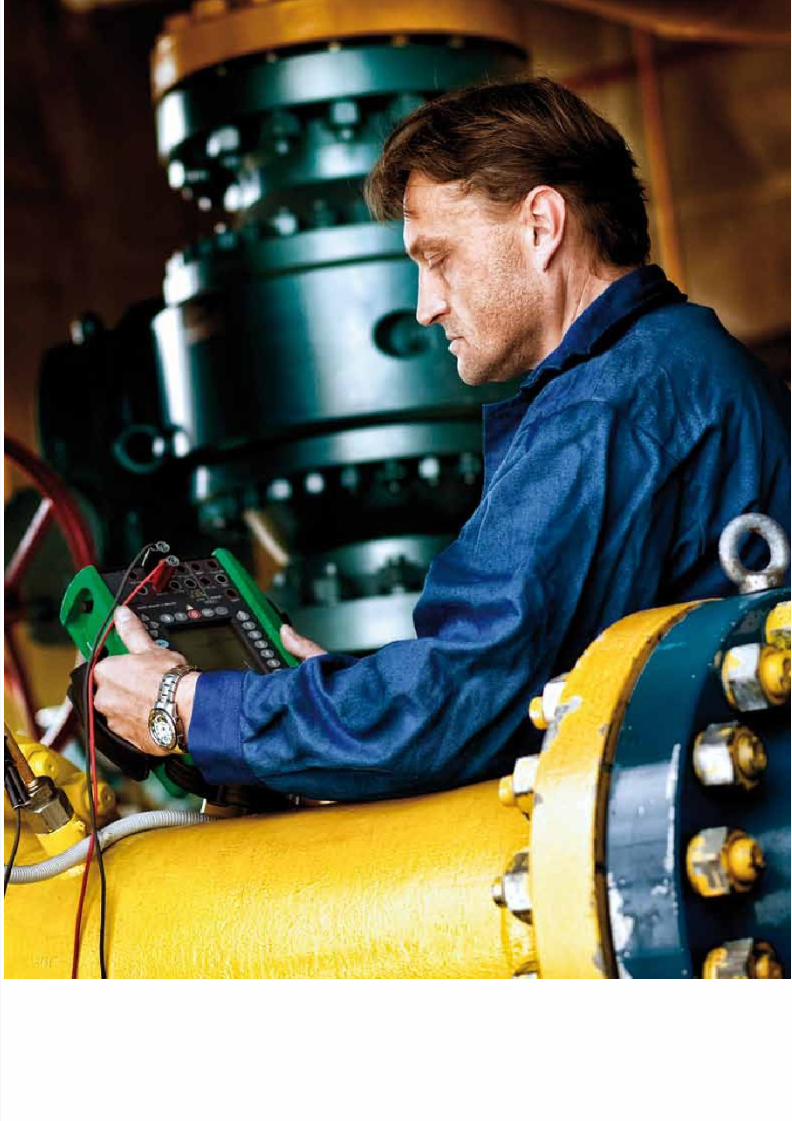
8/20/2019 Beamex Book Ultimate Calibration
http://slidepdf.com/reader/full/beamex-book-ultimate-calibration 174/204

8/20/2019 Beamex Book Ultimate Calibration
http://slidepdf.com/reader/full/beamex-book-ultimate-calibration 175/204
175
Fieldbus transmitters must also be calibrated just like conventional
instruments. There are also industrial environments where the
calibration of fieldbus instruments should not only be made
accurately and efficiently, but also safely. When safety becomes a top
priority issue in calibration, intrinsically safe fieldbus calibrators enterinto the picture.
By definition, intrinsic safety (IS) is a protection technique for
safely operating electronic equipment in explosive environments.
The concept has been developed for safely operating process control
instrumentation in hazardous areas. The idea behind intrinsic safety
is to make sure that the available electrical and thermal energy in a
system is always low enough that ignition of the hazardous atmosphere
cannot occur. A hazardous atmosphere is an area that contains
elements that may cause an explosion: source of ignition, a flammable
substance and oxygen.
An intrinsically safe calibrator is therefore designed to be incapable
of causing ignition in the surrounding environment with flammable
materials, such as gases, mists, vapors or combustible dust. Intrinsically
safe calibrators are also often referred to being “Ex calibrators”,
“calibrators for Ex Areas”, or “IS calibrators”. An Ex Area also refers
to an explosive environment and an Ex calibrator is a device designed
for use in the type of environment in question.
Where is intrinsically safe calibration required?
Many industries require intrinsically safe calibration equipment.
Intrinsically safe calibrators are designed for potentially explosive
environments, such as oil refineries, rigs and processing plants, gas
The safest way to calibrate
fieldbus instruments
Hazardous area
classifications in IEC/
European countries are:
Zone 0: an explosive gas
& air mixture is continuously
present or present for a long
time.
Zone 1: an explosive gas &
air mixture is likely to occur
in normal operation.
Zone 2: an explosive gas
& air mixture is not likely to
occur in normal operation,and if it occurs it will exist
only for a short time.

8/20/2019 Beamex Book Ultimate Calibration
http://slidepdf.com/reader/full/beamex-book-ultimate-calibration 176/204
176
pipelines and distribution centres, petrochemical and chemical plant
as well as pharmaceutical plants. Basically, any potentially explosiv
industrial environment can benefit from using intrinsically saf
calibrators.
What are the benefits of using intrinsically safe calibrators?
There are clear benefits in using intrinsically safe calibratio
equipment. First of all, it is the safest possible technique. Secondly
the calibrators provide performance and functionality.
Safest possible technique
Intrinsically safe calibrators are safe for employees, as they
can be safely used in environments where the risk of an
explosion exists. In addition, intrinsically safe calibrators
are the only technique permitted for Zone 0 environments
(explosive gas and air mixture is continuously present orpresent for a long time).
Performance and functionality
Multifunctional intrinsically safe calibrators provide
the functionality and performance of regular industrial
calibration devices, but in a safe way. They can be used
for calibration of pressure, temperature and electrical
signals. A documenting intrinsically safe calibrator, such
as the Beamex® MC5- IS, provides additional efficiency
improvements with its seamless communication with
calibration software. This eliminates the need of manualrecording of calibration data and improves the quality and
productivity of the entire calibration process.
Are intrinsically safe calibrators technically different from regula
industrial calibrators?
Intrinsically safe calibrators are different from other industria
calibrators in both design and technical features. In view of safety
there are also some guidelines and constraints for how to use them i
hazardous areas. Every intrinsically safe calibrator is delivered with
product safety note, which should be read carefully before using th
device. The product safety note lists all the “do’s and don’ts” for saf
calibration.
Basically, any potentially
explosive industrial
environment can benefit
from using intrinsically
safe calibrators.

8/20/2019 Beamex Book Ultimate Calibration
http://slidepdf.com/reader/full/beamex-book-ultimate-calibration 177/204
177
The differences in design and technical features were made with one
purpose in mind—to ensure that the device is safe to use and is unable
to cause an ignition. The surface of the device is made of conductive
material. The battery of an intrinsically safe calibrator is usually slower
to charge and it discharges quicker. Many times intrinsically safe
equipment operate only with dry batteries, but the Beamex intrinsicallysafe calibrators operate with chargeable batteries. When charging the
battery, it must be done in a non-Ex area. External pressure modules
can be used with IS-calibrators, but they must also be intrinsically
safe. There are also usually small differences with electrical ranges
compared to regular industrial calibrators (e.g. maximum is lower).
Making a calibrator safe and unable to cause ignition – typical
technical differences:
• Surface made of conductive material
• Constraints in using the device (listed in Product Safety Note)• Small differences with electrical ranges (e.g. maximum is lower)
• Battery slower to charge, quicker to discharge
• Battery must be charged in a non-Ex area
• When using external pressure modules, they must be IS-versions
What are ATEX and IECEx?
ATEX (“ATmosphères EXplosibles”, explosive atmospheres in French)
is a standard set in the European Union for explosion protection in the
industry. ATEX 95 equipment directive 94/9/EC concerns equipment
intended for use in potentially explosive areas. Companies in the
EU where the risk of explosion is evident must also use the ATEX
guidelines for protecting the employees. In addition, the ATEX rules
are obligatory for electronic and electrical equipment that will be used
in potentially explosive atmospheres sold in the EU as of July 1, 2003.
IEC (International Electrotechnical Commission) is a nonprofit
international standards organization that prepares and publishes
international standards for electrical technologies. The IEC TC/31
technical committee deals with the standards related to equipment for
explosive atmospheres. IECEx is an international scheme for certifying
procedures for equipment designed for use in explosive atmospheres.
The objective of the IECEx Scheme is to facilitate international trade
in equipment and services for use in explosive atmospheres, while
maintaining the required level of safety.
The differences in design
and technical features
were made with one
purpose in mind – to
ensure that the device is
safe to use and is unable
to cause an ignition.

8/20/2019 Beamex Book Ultimate Calibration
http://slidepdf.com/reader/full/beamex-book-ultimate-calibration 178/204
178
As Beamex® MC5-IS Intrinsically Safe Multifunction Calibrator
certified according to ATEX and the IECEx Scheme, it ensures th
calibrator is fit for its intended purpose and that suff icient informatio
is supplied with it to ensure that it can be used safely.
Is service different for intrinsically safe calibrators?
There are certain aspects that need special attention when doin
service or repair on an intrinsically safe calibrator. The most importan
thing to remember is that an intrinsically safe calibrator must maintai
its intrinsic safety after the service or repair. The best way to do th
is to send it to the manufacturer or to an authorized service compan
for repair. Recalibration can be done by calibration laboratories (sti
preferably with ISO/IEC 17025 accreditation).
Safe fieldbus calibration with the Beamex®
MC5-IS IntrinsicallySafe Multifunction Calibrator
The Beamex® MC5-IS Intrinsically Safe Multifunction Calibrato
is a high accuracy, all-in-one calibrator for extreme environment
Being an all-in-one calibrator, the MC5-IS replaces many individu
measurement devices and calibrators. The MC5-IS is also ATEX
and IECEx certified. The MC5-IS has calibration capabilitie
for pressure, temperature, electrical and frequency signals. It
a documenting calibrator, which means that it communicate
seamlessly with calibration software. Using documenting calibrato
with calibration software can remarkably improve the efficiency an
quality of the entire calibration process. The MC5-IS also has HAR
communication. The MC5-IS also has HART communication. Th
MC5-IS can also be used for calibrating Foundation Fieldbus H1 o
Profibus PA transmitters.
The most important thing
to remember is that an
intrinsically safe calibrator
must maintain its intrinsic
safety after the service or
repair.

8/20/2019 Beamex Book Ultimate Calibration
http://slidepdf.com/reader/full/beamex-book-ultimate-calibration 179/204

8/20/2019 Beamex Book Ultimate Calibration
http://slidepdf.com/reader/full/beamex-book-ultimate-calibration 180/204

8/20/2019 Beamex Book Ultimate Calibration
http://slidepdf.com/reader/full/beamex-book-ultimate-calibration 181/204
181
: 1
This glossary is a quick reference to the meaning of common
terms. It is a supplement to the VIM, GUM, NCSL Glossary,
and the information in the other references listed at the end.In technical, scientific and engineering work (such as metrology)
it is important to correctly use words that have a technical meaning.
Definitions of these words are in relevant national, international
and industry standards; journals; and other publications, as well as
publications of relevant technical and professional organizations.
Those documents give the intended meaning of the word, so everyone
in the business knows what it is. In technical work, only the technical
definitions should be used.
Many of these def initions are adapted from the references. In some
cases several may be merged to better clarify the meaning or adapt
the wording to common metrology usage. The technical definitions
may be different from the definitions published in common grammar
dictionaries. However, the purpose of common dictionaries is to record
the ways that people actually use words, not to standardize the way
the words should be used. If a word is defined in a technical standard, its
definition from a common grammar dictionary should never be used in work
where the technical standard can apply.
Calibration terminology
A to Z1
______________
1. Bucher, Jay L. 2004. The Metrology Handbook . Milwaukee: ASQ Quality Press.

8/20/2019 Beamex Book Ultimate Calibration
http://slidepdf.com/reader/full/beamex-book-ultimate-calibration 182/204
182
: 1
Terms that are not in this glossary may be found in one of thes
primary references:
1. ISO. 1993. International vocabulary of basic and general terms i
metrology (called the VIM); BIPM, IEC, IFCC, ISO, IUPAC
IUPAP, and OIML. Geneva: ISO.2. ANSI/NCSL. 1997. ANSI/NCSL Z540-2-1997, U. S. Guide to th
expression of uncertainty in measurement (called the GUM). Boulde
CO: NCSL International.
3. NCSL. 1999. NCSL Glossary of metrology-related terms. 2nd ed
Boulder, CO: NCSL International.
Some terms may be listed in this glossary in order to expand o
the definition, but should be considered an addition to the reference
listed above, not a replacement of them. (It is assumed that a calibratio
or metrology activity owns copies of these as part of its basic referenc
material.)
Glossary
Accreditation (of a laboratory) – Formal recognition by an accreditatio
body that a calibration or testing laboratory is able to competentl
perform the calibrations or tests listed in the accreditatio
scope document. Accreditation includes evaluation of both th
quality management system and the competence to perform th
measurements listed in the scope.
Accreditation body – An organization that conducts laborator
accreditation evaluations in conformance to ISO Guide 58.
Accreditation certificate – Document issued by an accreditatio
body to a laboratory that has met the conditions and criteria fo
accreditation. The certificate, with the documented measuremen
parameters and their best uncertainties, serves as proof of accredite
status for the time period listed. An accreditation certificat
without the documented parameters is incomplete.
Accreditation criteria – Set of requirements used by an accreditin
body that a laboratory must meet in order to be accredited.
Accuracy (of a measurement) – Accuracy is a qualitative indication o
how closely the result of a measurement agrees with the true valu
of the parameter being measured. (VIM, 3.5) Because the tru
value is always unknown, accuracy of a measurement is alway

8/20/2019 Beamex Book Ultimate Calibration
http://slidepdf.com/reader/full/beamex-book-ultimate-calibration 183/204
183
: 1
an estimate. An accuracy statement by itself has no meaning
other than as an indicator of quality. It has quantitative value
only when accompanied by information about the uncertainty
of the measuring system. Contrast with: accuracy (of a measuring
instrument)
Accuracy (of a measuring instrument) – Accuracy is a qualitativeindication of the ability of a measuring instrument to give
responses close to the true value of the parameter being measured.
(VIM, 5.18) Accuracy is a design specification and may be verified
during calibration. Contrast with: accuracy (of a measurement)
Application – Software installed on a defined platform/hardware
providing specific functionality
Assessment – Examination typically performed on-site of a testing or
calibration laboratory to evaluate its conformance to conditions
and criteria for accreditation.
Bespoke/Customized computerised system – A computerised system
individually designed to suit a specific business process Best measurement capability – For an accredited laboratory, the best
measurement capability for a particular quantity is “the smallest
uncertainty of measurement a laboratory can achieve within its
scope of accreditation when performing more or less routine
calibrations of nearly ideal measurement standards intended to
define, realize, conserve, or reproduce a unit of that quantity or
one or more of its values; or when performing more-or-less routine
calibrations of nearly ideal measuring instruments designed for the
measurement of that quantity.” (EA-4/02) The best measurement
capability is based on evaluations of actual measurements
using generally accepted methods of evaluating measurement
uncertainty.
Bias – Bias is the known systematic error of a measuring instrument.
(VIM, 5.25) The value and direction of the bias is determined by
calibration and/or gage R&R studies. Adding a correction, which
is always the negative of the bias, compensates for the bias. See also:
correction, systematic error
Calibration – (1). (See VIM 6.11 and NCSL pages 4–5 for primary
and secondary definitions.) Calibration is a term that has many
different – but similar – definitions. It is the process of verifying
the capability and performance of an item of measuring and test
equipment by comparison to traceable measurement standards.
Calibration is performed with the item being calibrated in

8/20/2019 Beamex Book Ultimate Calibration
http://slidepdf.com/reader/full/beamex-book-ultimate-calibration 184/204
184
: 1
its normal operating configuration – as the normal operato
would use it. The calibration process uses traceable externa
stimuli, measurement standards, or artifacts as needed to verif
the performance. Calibration provides assurance that th
instrument is capable of making measurements to its performanc
specif ication when it is correctly used. The result of a calibration a determination of the performance quality of the instrument wit
respect to the desired specifications. This may be in the form o
a pass/fail decision, determining or assigning one or more value
or the determination of one or more corrections. The calibratio
process consists of comparing an IM&TE unit with specifie
tolerances, but of unverified accuracy, to a measurement system
or device of specified capability and known uncertainty in orde
to detect, report, or minimize by adjustment any deviations from
the tolerance limits or any other variation in the accuracy of th
instrument being compared. Calibration is performed accordin
to a specified documented calibration procedure, under a set ospecified and controlled measurement conditions, and with
specified and controlled measurement system.
Notes:
• A requirement for calibration does not imply that the item
being calibrated can or should be adjusted.
• The calibration process may include, if necessary, calculatio
of correction factors or adjustment of the instrument bein
compared to reduce the magnitude of the inaccuracy.
• In some cases, minor repair such as replacement of batterie
fuses, or lamps, or minor adjustment such as zero and span
may be included as part of the calibration.
• Calibration does not include any maintenance or repair action
except as just noted. See also: performance test, calibratio
procedure Contrast with: calibration (2) and repair
Calibration – 2 A) Many manufacturers incorrectly use the term
calibration to name the process of alignment or adjustment o
an item that is either newly manufactured or is known to be ou
of tolerance, or is otherwise in an indeterminate state. Man
calibration procedures in manufacturers’ manuals are actuall
factory alignment procedures that only need to be performed if
UUC is in an indeterminate state because it is being manufactured

8/20/2019 Beamex Book Ultimate Calibration
http://slidepdf.com/reader/full/beamex-book-ultimate-calibration 185/204
185
: 1
is known to be out of tolerance, or after it is repaired. When used
this way, calibration means the same as alignment or adjustment,
which are repair activities and excluded from the metrological
definition of calibration.
(B) In many cases, IM&TE instruction manuals may use
calibration to describe tasks normally performed by the operatorof a measurement system. Examples include performing a self-
test as part of normal operation or performing a self-calibration
(normalizing) a measurement system before use. When calibration
is used to refer to tasks like this, the intent is that they are part
of the normal work done by a trained user of the system. These
and similar tasks are excluded from the metrological definition of
calibration. Contrast with: calibration (1) See also: normalization,
self-calibration, standardization
Calibration activity or provider – A laboratory or facility – including
personnel – that perform calibrations in an established location or
at customer location(s). It may be external or internal, includingsubsidiary operations of a larger entity. It may be called a calibration
laboratory, shop, or department; a metrology laboratory or
department; or an industry-specif ic name; or any combination or
variation of these.
Calibration certificate – (1) A calibration certificate is generally a
document that states that a specific item was calibrated by an
organization. The certificate identifies the item calibrated, the
organization presenting the certificate, and the effective date. A
calibration certificate should provide other information to allow
the user to judge the adequacy and quality of the calibration. (2)
In a laboratory database program, a certificate often refers to the
permanent record of the final result of a calibration. A laboratory
database certificate is a record that cannot be changed; if it is
amended later a new certificate is created. See also: calibration
report
Calibration procedure – A calibration procedure is a controlled
document that provides a validated method for evaluating and
verifying the essential performance characteristics, specifications,
or tolerances for a model of measuring or testing equipment.
A calibration procedure documents one method of verifying
the actual performance of the item being calibrated against its
performance specifications. It provides a list of recommended
calibration standards to use for the calibration; a means to record

8/20/2019 Beamex Book Ultimate Calibration
http://slidepdf.com/reader/full/beamex-book-ultimate-calibration 186/204
186
: 1
quantitative performance data both before and after adjustment
and information suff icient to determine if the unit being calibrate
is operating within the necessary performance specifications. A
calibration procedure always starts with the assumption that th
unit under test is in good working order and only needs to hav
its performance verified. Note: A calibration procedure does noinclude any maintenance or repair actions.
Calibration program – A calibration program is a process of th
quality management system that includes management of th
use and control of calibrated inspection, and test and measurin
equipment (IM&TE), and the process of calibrating IM&TE use
to determine conformance to requirements or used in supportin
activities. A calibration program may also be called a measuremen
management system (ISO 10012:2003).
Calibration report – A calibration report is a document that provide
details of the calibration of an item. In addition to the basic item
of a calibration certif icate, a calibration report includes details othe methods and standards used, the parameters checked, and th
actual measurement results and uncertainty. See also: calibratio
certificate
Calibration seal – A calibration seal is a device, placard, or label tha
when removed or tampered with, and by virtue of its design an
material, clearly indicates tampering. The purpose of a calibratio
seal is to ensure the integrity of the calibration. A calibration sea
is usually imprinted with a legend similar to “Calibration Voi
if Broken or Removed” or “Calibration Seal – Do Not Break o
Remove.” A calibration seal provides a means of deterring the use
from tampering with any adjustment point that can affect th
calibration of an instrument and detecting an attempt to acces
controls that can affect the calibration of an instrument. Note:
calibration seal may also be referred to as a tamper seal.
Calibration standard – (See VIM, 6.1 through 6.9, and 6.13, 6.14
and NCSL pages 36–38.) A calibration standard is an IM&T
item, artifact, standard reference material, or measuremen
transfer standard that is designated as being used only to perform
calibrations of other IM&TE items. As calibration standard
are used to calibrate other IM&TE items, they are more closel
controlled and characterized than the workload items they ar
used for. Calibration standards generally have lower uncertaint
and better resolution than general-purpose items. Designation as

8/20/2019 Beamex Book Ultimate Calibration
http://slidepdf.com/reader/full/beamex-book-ultimate-calibration 187/204
187
: 1
calibration standard is based on the use of the specific instrument,
however, not on any other consideration. For example, in a group
of identical instruments, one might be designated as a calibration
standard while the others are all general purpose IM&TE items.
Calibration standards are often called measurement standards. See
also: standard (measurement)Combined standard uncertainty – The standard uncertainty of the
result of a measurement, when that result is obtained from the
values of a number of other quantities. It is equal to the positive
square root of a sum of terms. The terms are the variances or
covariances of these other quantities, weighted according to how
the measurement result varies with changes in those quantities.
(GUM, 2.3.4) See also: expanded uncertainty
Commercial of the shelf software – Software commercially available,
whose fitness for use is demonstrated by a broad spectrum of users.
Competence – For a laboratory, the demonstrated ability to perform
the tests or calibrations within the accreditation scope and to meetother criteria established by the accreditation body. For a person,
the demonstrated ability to apply knowledge and skills. Note: The
word qualification is sometimes used in the personal sense, since
it is a synonym and has more accepted usage in the United States.
Confidence interval – A range of values that is expected to contain the
true value of the parameter being evaluated with a specif ied level
of confidence. The confidence interval is calculated from sample
statistics. Confidence intervals can be calculated for points, lines,
slopes, standard deviations, and so on. For an infinite (or very large
compared to the sample) population, the confidence interval is:
where
CI is the confidence interval,
n is the number of items in the sample,
p is the proportion of items of a given type in the population,
s is the sample standard deviation,
x is the sample mean, and
t is the Student’s T value for α ⁄2 and (n – 1) (α is the level of
significance).
s p (1 – p)
CI = x̄ ± t = ––– or CI = p ± –––––––––
n n

8/20/2019 Beamex Book Ultimate Calibration
http://slidepdf.com/reader/full/beamex-book-ultimate-calibration 188/204
188
: 1
Correction (of error) – A correction is the value that is added to th
raw result of a measurement to compensate for known or estimate
systematic error or bias. (VIM, 3.15) Any residual amount is treate
as random error. The correction value is equal to the negative o
the bias. An example is the value calculated to compensate fo
the calibration difference of a reference thermometer or for thcalibrated offset voltage of a thermocouple reference junction. S
also: bias, error, random error, systematic error
Corrective action – Corrective action is something done to correct
nonconformance when it arises, including actions taken to preven
reoccurrence of the nonconformance. Compare with: preventiv
action
Coverage factor – A numerical factor used as a multiplier of th
combined standard uncertainty in order to obtain an expande
uncertainty. (GUM, 2.3.6) The coverage factor is identified b
the symbol k . It is usually given the value 2, which approximatel
corresponds to a probability of 95 percent for degrees of freedom> 10’.
Deficiency – Nonfulfillment of conditions and/or criteria fo
accreditation, sometimes referred to as a nonconformance.
Departure value – A term used by a few calibration laboratories to refe
to bias, error or systematic error. The exact meaning can usually b
determined from examination of the calibration certificate.
Equivalence – (A) Acceptance of the competence of other nationa
metrology institutes (NMI), accreditation bodies, and/or accredite
organizations in other countries as being essentially equal to th
NMI, accreditation body, and/or accredited organizations withi
the host country.
(B) A formal, documented determination that a specific instrumen
or type of instrument is suitable for use in place of the one originall
listed, for a particular application.
Error (of measurement) – (See VIM, 3.10, 3.12–3.14; and NCSL page
11–13.) In metrology, error (or measurement error) is an estimat
of the difference between the measured value and the probabl
true value of the object of the measurement. The error ca
never be known exactly; it is always an estimate. Error may b
systematic and/or random. Systematic error (also known as bia
may be corrected. See also: bias, correction (of error), random erro
systematic error
Gage R&R – Gage repeatability and reproducibility study, whic

8/20/2019 Beamex Book Ultimate Calibration
http://slidepdf.com/reader/full/beamex-book-ultimate-calibration 189/204
189
: 1
(typically) employs numerous instruments, personnel, and
measurements over a period of time to capture quantitative
observations. The data captured are analyzed statistically to obtain
best measurement capability, which is expressed as an uncertainty
with a coverage factor of k = 2 to approximate 95 percent. The
number of instruments, personnel, measurements, and length oftime are established to be statistically valid consistent with the size
and level of activity of the organization.
GUM – An acronym commonly used to identify the ISO Guide to the
Expression of Uncertainty in Measurement. In the United States, the
equivalent document is ANSI/NCSL Z540-2-1997, U. S. Guide to
the Expression of Uncertainty in Measurement.
IM&TE – The acronym IM&TE refers to inspection, measuring,
and test equipment. This term includes all items that fall under
a calibration or measurement management program. IM&TE
items are typically used in applications where the measurement
results are used to determine conformance to technical or qualityrequirements before, during, or after a process. Some organizations
do not include instruments used solely to check for the presence
or absence of a condition (such as voltage, pressure, and so on)
where a tolerance is not specif ied and the indication is not critical
to safety. Note: Organizations may refer to IM&TE items as MTE
(measuring and testing equipment), TMDE (test, measuring,
and diagnostic equipment), GPETE (general purpose electronic
test equipment), PME (precision measuring equipment), PMET
(precision measuring equipment and tooling), or SPETE (special
purpose electronic test equipment).
Inte rlaboratory comparison – Organization, performance, and
evaluation of tests or calibrations on the same or similar items
or materials by two or more laboratories in accordance with
predetermined conditions.
Internal audit – A systematic and documented process for obtaining
audit evidence and evaluating it objectively to verify that a
laboratory’s operations comply with the requirements of its quality
system. An internal audit is done by or on behalf of the laboratory
itself, so it is a first-party audit.
International Organization for Standardization (ISO) – An international
nongovernmental organization chartered by the United Nations
in 1947, with headquarters in Geneva, Switzerland. The mission
of ISO is “to promote the development of standardization and
8/20/2019 Beamex Book Ultimate Calibration
http://slidepdf.com/reader/full/beamex-book-ultimate-calibration 190/204
190
: 1
related activities in the world with a view to facilitating th
international exchange of goods and services, and to developin
cooperation in the spheres of intellectual, scientific, technologic
and economic activity.” The scope of ISO’s work covers all f ields o
business, industry and commerce except electrical and electroni
engineering. The members of ISO are the designated nationastandards bodies of each country. (The United States is represente
by ANSI.) See also: ISO
International System of Units (SI) – A defined and coherent system o
units adopted and used by international treaties. (The acronym S
is from the French Systéme International.) SI is international system
of measurement for all physical quantities. (Mass, length, amoun
of substance, time, electric current, thermodynamic temperatur
and luminous intensity.) SI units are defined and maintained b
the International Bureau of Weights and Measures (BIPM) in Pari
France. The SI system is popularly known as the metric system.
ISO – Iso is a Greek word root meaning equal. The InternationaOrganization for Standardization chose the word as the sho
form of the name, so it will be a constant in all languages. In th
context, ISO is not an acronym. (If the acronym was based on th
full name were used, it would be different in each language.) Th
name also symbolizes the mission of the organization – to equaliz
standards worldwide.
IT Infrastructure – The hardware and software such as networkin
software and operation systems, which makes it possible for th
application to function.
Level of confidence – Defines an interval about the measurement resu
that encompasses a large fraction p of the probability distributio
characterized by that result and its combined standard uncertainty
and p is the coverage probability or level of confidence of th
interval. Effectively, the coverage level expressed as a percent.
Life cycle – All phases in the life of the system from initial requiremen
until retirement including design, specification, programming
testing, installation, operation, and maintenance.
Management review – The planned, formal, periodic, and schedule
examination of the status and adequacy of the quality managemen
system in relation to its quality policy and objectives by th
organization’s top management.
Measurement – A set of operations performed for the purpose o
determining the value of a quantity. (VIM, 2.1)

8/20/2019 Beamex Book Ultimate Calibration
http://slidepdf.com/reader/full/beamex-book-ultimate-calibration 191/204
191
: 1
Measurement system – A measurement system is the set of equipment,
conditions, people, methods, and other quantifiable factors that
combine to determine the success of a measurement process.
The measurement system includes at least the test and measuring
instruments and devices, associated materials and accessories, the
personnel, the procedures used, and the physical environment.Metrology – Metrology is the science and practice of measurement
(VIM, 2.2).
Mobile operations – Operations that are independent of an established
calibration laboratory facility. Mobile operations may include work
from an off ice space, home, vehicle, or the use of a virtual off ice.
Natural (physical) constant – A natural constant is a fundamental
value that is accepted by the scientific community as valid. Natural
constants are used in the basic theoretical descriptions of the
universe. Examples of natural physical constants important in
metrology are the speed of light in a vacuum (c), the triple point of
water (273.16 K), the quantum charge ratio (h/e), the gravitationalconstant (G), the ratio of a circle’s circumference to its diameter
(p), and the base of natural logarithms (e).
NCSL international – Formerly known as the National Conference
of Standards Laboratories (NCSL). NCSL was formed in
1961 to “promote cooperative efforts for solving the common
problems faced by measurement laboratories. NCSL has member
organizations from academic, scientific, industrial, commercial
and government facilities around the world. NCSL is a nonprofit
organization, whose membership is open to any organization with
an interest in the science of measurement and its application in
research, development, education, or commerce. NCSL promotes
technical and managerial excellence in the field of metrology,
measurement standards, instrument calibration, and test and
measurement.”
Normalization, Normalize – See: self-calibration
Offset – Offset is the difference between a nominal value (for an
artifact) or a target value (for a process) and the actual measured
value. For example, if the thermocouple alloy leads of a reference
junction probe are formed into a measurement junction and placed
in an ice point cell, and the reference junction itself is also in the
ice point, then the theoretical thermoelectric emf measured at the
copper wires should be zero. Any value other than zero is an offset
created by inhomogeneity of the thermocouple wires combined

8/20/2019 Beamex Book Ultimate Calibration
http://slidepdf.com/reader/full/beamex-book-ultimate-calibration 192/204
192
: 1
with other uncertainties. Compare with: bias, error
On-site operations – Operations that are based in or directly supporte
by an established calibration laboratory facility, but actuall
perform the calibration actions at customer locations. This include
climate-controlled mobile laboratories.
Performance Test – A performance test (or performance verification) the activity of verifying the performance of an item of measurin
and test equipment to provide assurance that the instrument
capable of making correct measurements when it is properly used
A performance test is done with the item in its normal operatin
configuration. A performance test is the same as a calibration (1
See also: calibration (1)
Policy – A policy defines and sets out the basic objectives, goal
vision, or general management position on a specific topic. A
policy describes what management intends to have done regardin
a given portion of business activity. Policy statements relevant t
the quality management system are generally stated in the qualitmanual. Policies can also be in the organization’s policy/procedur
manual. See also: procedure
Precision – Precision is a property of a measuring system or instrumen
Precision is a measure of the repeatability of a measuring system – how
much agreement there is within a group of repeated measuremen
of the same quantity under the same conditions. (NCSL, page 26
Precision is not the same as accuracy. (VIM, 3.5)
Preventive action – Preventive action is something done to prevent th
possible future occurrence of a nonconformance, even though suc
an event has not yet happened. Preventive action helps improve th
system. Contrast with: corrective action
Procedure – A procedure describes a specific process for implementin
all or a portion of a policy. There may be more than one procedur
for a given policy. A procedure has more detail than a policy bu
less detail than a work instruction. The level of detail neede
should correlate with the level of education and training of th
people with the usual qualif ications to do the work and the amoun
of judgment normally allowed to them by management. Som
policies may be implemented by fairly detailed procedures, whil
others may only have a few general guidelines. Calibration: se
calibration procedure. See also: policy
Process owner – The person responsible for the business process.

8/20/2019 Beamex Book Ultimate Calibration
http://slidepdf.com/reader/full/beamex-book-ultimate-calibration 193/204
193
: 1
Proficiency testing – Determination of laboratory testing performance
by means of interlaboratory comparisons.
Quality manual – The quality manual is the document that describes
the quality management policy of an organization with respect to a
specified conformance standard. The quality manual briefly defines
the general policies as they apply to the specified conformancestandard and affirms the commitment of the organization’s top
management to the policy. In addition to its regular use by the
organization, auditors use the quality manual when they audit
the quality management system. The quality manual is generally
provided to customers on request. Therefore, it does not usually
contain any detailed policies and never contains any procedures,
work instructions, or proprietary information.
Random error – Random error is the result of a single measurement of
a value, minus the mean of a large number of measurements of the
same value. (VIM, 3.13) Random error causes scatter in the results
of a sequence of readings and, therefore, is a measure of dispersion.Random error is usually evaluated by Type A methods, but Type
B methods are also used in some situations. Note: Contrary to
popular belief, the GUM specifically does not replace random
error with either Type A or Type B methods of evaluation. See also:
error Compare with: systematic error
Repair – Repair is the process of returning an unserviceable or
nonconforming item to serviceable condition. The instrument is
opened, or has covers removed, or is removed from its case and
may be disassembled to some degree. Repair includes adjustment
or alignment of the item as well as component-level repair. (Some
minor adjustment such as zero and span may be included as part of
the calibration.) The need for repair may be indicated by the results
of a calibration. For calibratable items, repair is always followed by
calibration of the item. Passing the calibration test indicates success
of the repair. Contrast with: calibration (1), repair (minor)
Repair (minor) – Minor repair is the process of quickly and economically
returning an unserviceable item to serviceable condition by doing
simple work using parts that are in stock in the calibration lab.
Examples include replacement of batteries, fuses, or lamps; or
minor cleaning of switch contacts; or repairing a broken wire; or
replacing one or two in-stock components. The need for repair may
be indicated by the results of a calibration. For calibratable items,
minor repair is always followed by calibration of the item. Passing

8/20/2019 Beamex Book Ultimate Calibration
http://slidepdf.com/reader/full/beamex-book-ultimate-calibration 194/204
194
: 1
the calibration test indicates success of the repair. Minor repairs a
defined as repairs that take no longer than a short time as define
by laboratory management, and where no parts have to be ordere
from external suppliers, and where substantial disassembly of th
instrument is not required. Contrast with: calibration (1), repair
Reported value – One or more numerical results of a calibratioprocess, with the associated measurement uncertainty, as recorde
on a calibration report or certificate. The specific type and forma
vary according to the type of measurement being made. In genera
most reported values will be in one of these formats:
• Measurement result and uncertainty. The reported value
usually the mean of a number of repeat measurements. Th
uncertainty is usually expanded uncertainty as def ined in th
GUM.
• Deviation from the nominal (or reference) value an
uncertainty. The reported value is the difference betwee
the nominal value and the mean of a number of repeameasurements. The uncertainty of the deviation is usuall
expanded uncertainty as defined in the GUM.
• Estimated systematic error and uncertainty. The value may b
reported this way when it is known that the instrument is pa
of a measuring system and the systematic error will be use
to calculate a correction that will apply to the measuremen
system results.
Round robin – See: Interlaboratory Comparison
Scope of accreditation – For an accredited calibration or testin
laboratory, the scope is a documented list of calibration or testin
fields, parameters, specific measurements, or calibrations an
their best measurement, uncertainty. The scope document is a
attachment to the certificate of accreditation and the certificate
incomplete without it. Only the calibration or testing areas tha
the laboratory is accredited for are listed in the scope documen
and only the listed areas may be offered as accredited calibration
or tests. The accreditation body usually defines the format an
other details.
Self-calibration – Self-calibration is a process performed by a user fo
the purpose of making an IM&TE instrument or system read
for use. The process may be required at intervals such as ever
power-on sequence; or once per shift, day, or week of continuou
operation; or if the ambient temperature changes by a specifie

8/20/2019 Beamex Book Ultimate Calibration
http://slidepdf.com/reader/full/beamex-book-ultimate-calibration 195/204
195
: 1
amount. Once initiated, the process may be performed totally by the
instrument or may require user intervention and/or use of external
calibrated artifacts. The usual purpose is accuracy enhancement
by characterization of errors inherent in the measurement system
before the item to be measured is connected. Self-calibration is
not equivalent to periodic calibration (performance verification)because it is not performed using a calibration procedure and does
not meet the metrological requirements for calibration. Also, if
an instrument requires self-calibration before use, then that will
also be accomplished at the start of a calibration procedure. Self-
calibration may also be called normalization or standardization.
Compare with: calibration (2.B) Contrast with: calibration (1)
Specification – In metrology, a specification is a documented statement
of the expected performance capabilities of a large group of
substantially identical measuring instruments, given in terms of
the relevant parameters and including the accuracy or uncertainty.
Customers use specifications to determine the suitability of aproduct for their own applications. A product that performs
outside the specification limits when tested (calibrated) is rejected
for later adjustment, repair, or scrapping.
Standard (document) – A standard (industry, national, government, or
international standard; a norme ) is a document that describes the
processes and methods that must be performed in order to achieve
a specific technical or management objective, or the methods for
evaluation of any of these. An example is ANSI/NCSL Z540-1-
1994, a national standard that describes the requirements for the
quality management system of a calibration organization and the
requirements for calibration and management of the measurement
standards used by the organization.
Standard (measurement) – A standard (measurement standard,
laboratory standard, calibration standard, reference standard; an
étalon) is a system, instrument, artifact, device, or material that
is used as a defined basis for making quantitative measurements.
The value and uncertainty of the standard define a limit to the
measurements that can be made: a laboratory can never have better
precision or accuracy than its standards. Measurement standards
are generally used in calibration laboratories. Items with similar
uses in a production shop are generally regarded as working-level
instruments by the calibration program.
Primary standard. Accepted as having the highest metrological

8/20/2019 Beamex Book Ultimate Calibration
http://slidepdf.com/reader/full/beamex-book-ultimate-calibration 196/204
196
: 1
qualities and whose value is accepted without reference to othe
standards of the same quantity. Examples: triple point of water ce
and caesium beam frequency standard.
Transfer standard. A device used to transfer the value of
measurement quantity (including the associated uncertainty) from
a higher level to a lower level standard.Secondary standard. The highest accuracy level standards in
particular laboratory generally used only to calibrate workin
standards. Also called a reference standard.
Working standard. A standard that is used for routine calibratio
of IM&TE. The highest level standards, found in national an
international metrology laboratories, are the realizations o
representations of SI units. See also: calibration standard
Standard operating procedure (SOP) – A term used by some organization
to identify policies, procedures, or work instructions.
Standard reference material – A standard reference material (SRM) a
defined by NIST “is a material or artifact that has had one or morof its property values certified by a technically valid procedure
and is accompanied by, or traceable to, a certificate or othe
documentation which is issued by NIST… Standard referenc
materials are…manufactured according to strict specification
and certified by NIST for one or more quantities of interes
SRMs represent one of the primary vehicles for disseminatin
measurement technology to industry.”
Standard uncertainty – The uncertainty of the result of a measuremen
expressed as a standard deviation. (GUM, 2.3.1)
Standardization – See: self-calibration.
Systematic error – A systematic error is the mean of a large number o
measurements of the same value minus the (probable) true valu
of the measured parameter. (VIM, 3.14) Systematic error causes th
average of the readings to be offset from the true value. Systemat
error is a measure of magnitude and may be corrected. Systemat
error is also called bias when it applies to a measuring instrumen
Systematic error may be evaluated by Type A or Type B method
according to the type of data available. Note: Contrary to popula
belief, the GUM specifically does not replace systematic error wit
either Type A or Type B methods of evaluation. (3.2.3, note) S
also: bias, error, correction (of error) Compare with: random erro

8/20/2019 Beamex Book Ultimate Calibration
http://slidepdf.com/reader/full/beamex-book-ultimate-calibration 197/204
197
: 1
System owner – The person responsible for the availability, and
maintenance of a computerised system and for the security of the
data residing on that system.
Test accuracy ratio – (1) In a calibration procedure, the test accuracy
ratio (TAR) is the ratio of the accuracy tolerance of the unit under
calibration to the accuracy tolerance of the calibration standardused. (NCSL, page 2)
TAR = UUT_tolerance
STD_tolerance
The TAR must be calculated using identical parameters and units
for the UUC and the calibration standard. If the accuracy tolerances
are expressed as decibels, percentage, or another ratio, they must
be converted to absolute values of the basic measurement units.
(2) In the normal use of IM&TE items, the TAR is the ratio of
the tolerance of the parameter being measured to the accuracytolerance of the IM&TE. Note: TAR may also be referred to as the
accuracy ratio or (incorrectly) the uncertainty ratio.
Test uncertainty ratio – In a calibration procedure, the test uncertainty
ratio (TUR) is the ratio of the accuracy tolerance of the unit under
calibration to the uncertainty of the calibration standard used.
(NCSL, page 2)
TUR = UUT_tolerance
STD_uncert
The TUR must be calculated using identical parameters and units
for the UUC and the calibration standard. If the accuracy tolerances
are expressed as decibels, percentage, or another ratio, they must be
converted to absolute values of the basic measurement units. Note:
The uncertainty of a measurement standard is not necessarily the
same as its accuracy specification.
Third Party – Parties
Tolerance – A tolerance is a design feature that defines limits within
which a quality characteristic is supposed to be on individual parts;
it represents the maximum allowable deviation from a specified
value. Tolerances are applied during design and manufacturing. A
tolerance is a property of the item being measured. Compare with:
specification, uncertainty

8/20/2019 Beamex Book Ultimate Calibration
http://slidepdf.com/reader/full/beamex-book-ultimate-calibration 198/204
198
: 1
Traceable, traceability – Traceability is a property of the result of
measurement, providing the ability to relate the measurement resu
to stated references, through an unbroken chain of comparison
each having stated uncertainties. (VIM, 6.10) Traceability is
demonstrated or implied property of the result of a measuremen
to be consistent with an accepted standard within specified limiof uncertainty. (NCSL, pages 42–43) The stated references ar
normally the base or supplemental SI units as maintained by
national metrology institute; fundamental or physical natura
constants that are reproducible and have defined values; ratio typ
comparisons; certified standard reference materials; or industr
or other accepted consensus reference standards. Traceabilit
provides the ability to demonstrate the accuracy of a measuremen
result in terms of the stated reference. Measurement assuranc
methods applied to a calibration system include demonstratio
of traceability. A calibration system operating under a program
controls system only implies traceability. Evidence of traceabilitincludes the calibration report (with values and uncertainty
of calibration standards, but the report alone is not sufficien
The laboratory must also apply and use the data. A calibratio
laboratory, a measurement system, a calibrated IM&TE,
calibration report, or any other thing is not and be traceable to
national standard. Only the result of a specif ic measurement ca
be said to be traceable, provided all of the conditions just listed ar
met. Reference to a NIST test number is specifically not evidence o
traceability. That number is merely a catalog number of the specif
service provided by NIST to a customer so it can be identified o
a purchase order.
Transfer measurement – A transfer measurement is a type of method tha
enables making a measurement to a higher level of resolution tha
normally possible with the available equipment. Common transfe
methods are differential measurements and ratio measurements
Transfer standard – A transfer standard is a measurement standard use
as an intermediate device when comparing two other standard
(VIM, 6.8) Typical applications of transfer standards are to transfe
a measurement parameter from one organization to another, from
a primary standard to a secondary standard, or from a secondar
standard to a working standard in order to create or maintai
measurement traceability. Examples of typical transfer standard
are DC volt sources (standard cells or zener sources), and singl
value standard resistors, capacitors, or inductors.

8/20/2019 Beamex Book Ultimate Calibration
http://slidepdf.com/reader/full/beamex-book-ultimate-calibration 199/204
199
: 1
Type A evaluation (of uncertainty) – Type A evaluation of measurement
uncertainty is the statistical analysis of actual measurement results
to produce uncertainty values. Both random and systematic error
may be evaluated by Type A methods. (GUM, 3.3.3 through
3.3.5) Uncertainty can only be evaluated by Type A methods if
the laboratory actually collects the data.Type B evaluation (of uncertainty) – Type B evaluation of measurement
uncertainty includes any method except statistical analysis of
actual measurement results. Both random and systematic error
may be evaluated by Type B methods. (GUM, 3.3.3 through 3.3.5)
Data for evaluation by Type B methods may come from any source
believed to be valid.
Uncertainty – Uncertainty is a property of a measurement result
that defines the range of probable values of the measurand.
Total uncertainty may consist of components that are evaluated
by the statistical probability distribution of experimental data
or from assumed probability distributions based on other data.Uncertainty is an estimate of dispersion; effects that contribute
to the dispersion may be random or systematic. (GUM, 2.2.3)
Uncertainty is an estimate of the range of values that the true value
of the measurement is within, with a specified level of confidence.
After an item that has a specified tolerance has been calibrated
using an instrument with a known accuracy, the result is a value
with a calculated uncertainty. See also: Type A evaluation, Type B
evaluation
Uncertainty budget – The systematic description of known uncertainties
relevant to specific measurements or types of measurements,
categorized by type of measurement, range of measurement, and/
or other applicable measurement criteria.
UUC, UUT – The unit under calibration or the unit under test – the
instrument being calibrated. These are standard generic labels for
the IM&TE item that is being calibrated, which are used in the text
of the calibration procedure for convenience. Also may be called
device under test (DUT) or equipment under test (EUT).
Validation – Substantiation by examination and provision of objective
evidence that verified processes, methods, and/or procedures are
fit for their intended use.
Verification – Confirmation by examination and provision of objective
evidence that specified requirements have been fulf illed.
VIM – An acronym commonly used to identify the ISO International

8/20/2019 Beamex Book Ultimate Calibration
http://slidepdf.com/reader/full/beamex-book-ultimate-calibration 200/204
200
Vocabulary of Basic and General Terms in Metrology. (The acronym
comes from the French title.)
Work Instruction – In a quality management system, a work instructio
defines the detailed steps necessary to carry out a procedure
Work instructions are used only where they are needed to ensur
the quality of the product or service. The level of education antraining of the people with the usual qualifications to do th
work must be considered when writing a work instruction. In
metrology laboratory, a calibration procedure is a type of wor
instruction.
1. Bucher, Jay L. 2004. The Metrology Handbook. Milwaukee: ASQ
Quality Press.
: 1

8/20/2019 Beamex Book Ultimate Calibration
http://slidepdf.com/reader/full/beamex-book-ultimate-calibration 201/204
201

8/20/2019 Beamex Book Ultimate Calibration
http://slidepdf.com/reader/full/beamex-book-ultimate-calibration 202/204
202
PROFESSIONAL SERVICES
PORTABLE CALIBRATORS
WORKSTATIONS
CALIBRATION SOFTWARE

8/20/2019 Beamex Book Ultimate Calibration
http://slidepdf.com/reader/full/beamex-book-ultimate-calibration 203/204
203
About Beamex
• One of the world’s leading providers of calibration
solutions.
• Develops and manufactures high-quality
calibration equipment, software, systems and
services for the calibration and maintenance of
process instruments.
• Certified in accordance with the ISO 9001:2008
quality standard.
• Comprehensive product range includes portable
calibrators, workstations, calibration software,
accessories, professional services and industry-
specific solutions.
• Products and services available in more than
60 countries. More than 10,000 companies
worldwide utilize Beamex’s calibration solutions.
• Customers from wide range of industries, such
as automotive, aviation, contractor engineering,
education, food and beverage, manufacturing,
marine, metal and mining, nuclear, oil and gas,
petrochemical and chemical, pharmaceutical,
power and energy, and pulp and paper.
• For customers with requirements for accuracy,
versatility, efficiency, ease-of-use and reliability.
• Beamex’s Accredited Calibration Laboratory
is accredited and approved by FINAS (Finnish
Accreditation Service). FINAS is a member of all
Multilateral Recognition Agreements / Mutual
Recognition Arrangements (MLA/MRA) signed by
European and other international organizations,
i.e. European co-operation for Accreditation
(EA), International Laboratory Accreditation
Cooperation (ILAC) and International
Accreditation Forum Inc. (IAF).
Why is Beamex better
Accuracy assured
Accuracy is assured when you
decide to purchase a Beamex®
calibrator. They are all delivered with
a traceable, accredited calibration
certificate.
Integrated calibration solutions
Beamex calibrators, workstations,
calibration software and professional
services form an integrated,
automated system.
Industry pioneer
with global presence
A forerunner in developing
high-quality calibration equipment
and software, with global customer
base and partner network.
High customer satisfaction
Constantly improving understanding
of customer needs and developing
solutions to meet them.
Support
Installation, training, validation,
system integration, database
conversion, Help Desk and
re-calibration services available.

8/20/2019 Beamex Book Ultimate Calibration
http://slidepdf.com/reader/full/beamex-book-ultimate-calibration 204/204