bcga code of practice cp7 - bcga code of practice cp7 the safe use of oxy-fuel gas equipment...
TRANSCRIPT
BCG
The (Ind
A CODE OF PRACTICE CP7
Safe Use of Oxy-Fuel Gas Equipmentividual Portable or Mobile Cylinder
Supply)
Revision 4 : 2004

BC
The (In
BCGA CP7 Rev 4
Copyright © 2004 by British Compressed Gases Association. First printed 1986. All rights reserved. No part of this publication may be reproduced or transmitted in any form or by any means, electronic or mechanical, including photocopy, without permission from the publisher:
BRITISH COMPRESSED GASES ASSOCIATION 6 St. Mary’s Street, Wallingford, OX10 0EL
Tel: 0044 (0)1491 825533 Fax: 0044 (0)1491 826689Website: www.bcga.co.uk
E-mail: [email protected]
ISSN 0260-4809
© 200
GA CODE OF PRACTICE CP7
Safe Use of Oxy-Fuel Gas Equipmentdividual Portable or Mobile Cylinder
Supply)
Revision 4 : 2004
4

PREFACE
The various publications issued by the British Compressed Gases Association have the objective of establishing consistency in design, construction practices and user operational and maintenance procedures, in order to establish high standards of reliability and safety in the interests of employers, employees and the general public. The Association endeavours to compile these documents using the best sources of information known at the date of issue. The information is used in good faith and belief in its accuracy. The publications are intended for use by technically competent persons and their application does not, therefore, remove the need for technical and managerial judgement in practical situations and with due regard to local circumstances, nor do they confer any immunity or exemption from relevant legal requirements, including by-laws. The onus of responsibility for their application lies with the user. The Association, its officers, its members and individual members of any Working Parties can accept no legal liability or responsibility whatsoever, howsoever arising, for the consequences of the use or misuse of the publications. For the assistance of users, references are given, either in the text or Appendices, to publications such as British, European and International Standards and Codes of Practice, and current legislation that may be applicable. The intention of BCGA is that this document should be read and used in the context of these references where the subjects have a bearing on the local application of the processes or operations carried out by the user. BCGA’s publications are reviewed, and revised if necessary, at three-yearly intervals. Readers are advised to check the list of publications on the Association’s website www.bcga.co.uk to ensure that the copy in their possession is the current version.
BCGA CP7 Rev 4 © 2004

CONTENTS
TERMINOLOGY AND DEFINITIONS ....................................................................1
1 INTRODUCTION .......................................................................................................4
2 SCOPE .........................................................................................................................5
3 SOME PROPERTIES OF THE GASES USED..........................................................5
3.1 Oxygen.........................................................................................................................5
3.2 Liquefied Petroleum Gases (LPG) – Propane, Butane, etc .........................................6
3.3 Acetylene .....................................................................................................................6
3.4 Hydrogen .....................................................................................................................6
4 PROCESS HAZARDS ................................................................................................6
4.1 Backfire........................................................................................................................6
4.2 Sustained Backfire .......................................................................................................6
4.3 Intermittent Backfire....................................................................................................7
4.4 Flashback .....................................................................................................................7
4.5 Backflow......................................................................................................................7
4.6 Decomposition.............................................................................................................7
4.7 Oxygen Ignition ...........................................................................................................7
4.8 Products of Combustion ..............................................................................................7
4.9 Fumes...........................................................................................................................7
4.10 Maintenance.................................................................................................................7
5 PRESSURE SYSTEMS SAFETY REGULATIONS .................................................8
5.1 Introduction..................................................................................................................8
5.2 Provision of Information and Marking ........................................................................8
5.3 Written Scheme of Examination..................................................................................8
5.4 Maintenance.................................................................................................................8
TABLE 1 - GUIDANCE ON MAINTENANCE ......................................................10
6 SAFETY PRECAUTIONS – EQUIPMENT.............................................................11
BCGA CP7 Rev 4 © 2004

6.1 Pressure Regulators ...................................................................................................11
6.2 Hoses..........................................................................................................................11
6.3 Blowpipes ..................................................................................................................12
6.4 Non-Return Valve......................................................................................................12
6.5 Personal Safety Wear.................................................................................................13
7 PROVISION OF SAFETY DEVICES......................................................................13
7.1 Safety Devices ...........................................................................................................13
7.2 Installation Requirements ..........................................................................................13
8 SAFETY PRECAUTIONS – WORKING AREA ....................................................14
8.1 General.......................................................................................................................14
8.2 Confined Spaces ........................................................................................................15
8.3 Oxygen Enrichment ...................................................................................................16
8.4 Work on Vessels and Tanks ......................................................................................16
9 CYLINDER HANDLING AND STORAGE............................................................17
9.1 Cylinder Handling .....................................................................................................17
9.2 Cylinder Storage ........................................................................................................18
10 PREPARATION FOR USE ......................................................................................18
10.1 Location of Cylinders ................................................................................................18
10.2 Cylinders....................................................................................................................18
10.3 Regulators ..................................................................................................................19
10.4 Safety Devices ...........................................................................................................19
10.5 Hose ...........................................................................................................................19
10.6 Blowpipes ..................................................................................................................19
10.7 Pressurising the System .............................................................................................19
10.8 System Purging..........................................................................................................20
10.9 Lighting Up................................................................................................................20
11 CLOSING DOWN PROCEDURE............................................................................20
12 GENERAL EMERGENCY PROCEDURE ..............................................................21
BCGA CP7 Rev 4 © 2004

12.1 Sustained Backfire......................................................................................................21
12.2 Flashback/Self Extinguishing Backfire .....................................................................21
13 EMERGENCY PROCEDURE: CYLINDERS .........................................................22
14 REFERENCES ..........................................................................................................24
APPENDIX 1 - Recommended installation providing increased safety ...................28
APPENDIX 1 - Minimum Requirement for all hose sizes and lengths ...................29
HISTORY AND OBJECTIVES OF BCGA..............................................................30
BCGA CP7 Rev 4 © 2004

TERMINOLOGY AND DEFINITIONS
The following describes the function of the main items of equipment and explains the meaning of significant terms used in this Code. The references quoted in Section 14 should be consulted for more detailed and precise information.
Pressure Regulator
Fitted to the outlet of the gas cylinder valve, the pressure regulator reduces the pressure of the gas from cylinder pressure to the constant lower pressure required for the operation of the equipment.
Regulators may be designed to be adjustable in respect of outlet pressure or, for single purpose applications, may be pre-set. They shall conform to BS EN ISO 2503.
Pressure reduction within the regulator may be in one or two stages (single or two-stage regulators).
Blowpipe A piece of equipment in which separate supplies of oxygen and fuel gas are mixed in the appropriate proportions to obtain the required flame. They shall conform to BS EN ISO 5172.
A number of gas mixing systems can be employed either in the shank, between the shank and the blowpipe nozzle or in the nozzle and these may call for different working procedures.
Some blowpipes may, by an interchange of components, be adapted to carry out a wide range of duties.
Hose Assemblies The means by which the gases are conveyed from the regulator to the blowpipe. The hose shall conform to BS EN 559 and shall be colour coded as follows:
Oxygen BLUE
LPG or Methane ORANGE
Acetylene and other fuel gases excluding LPG or Methane RED
The hose connections shall conform to BS EN 560 and the hose assembly shall have been tested to the requirements of BS EN 1256.
BCGA CP7 Rev 4 © 2004 1

Mixing Systems That part of the blowpipe to which gases are separately conducted and in which the mixing of gases takes place. The mixer may require the provision of gases at approximately equal pressures (an equal pressure mixer), or may require relatively higher oxygen pressure in relation to that of the fuel gas (an injector mixer). A mixer may be matched to a range of nozzle orifice sizes or to only one.
Mixers shall conform to BS EN ISO 5172 and may be detachable units or integral with the blowpipe. They may also derive from assembly by the operator of matching parts. They may be located in the shank, neck, head or nozzle (nozzle mix) of the blowpipe.
Nozzle That part of the blowpipe, which provides the final control of velocity and gas profile as a gas or gases emerge to the atmosphere.
Safety Device A device which, when correctly used and placed, prevents any damage or injury from misuse or malfunction of the blowpipe or associated equipment. The various devices shall conform to BS EN 730.
Multi-functional Safety Device
A unit, which embodies two or more of the safety devices as defined in the following 5 items.
Flashback Arrestor A device which quenches a flame front (caused by flashback or decomposition) and which is suitable for the most severe type of flame, which may occur, i.e. detonation. It shall be effective in stopping a flame coming from either one or both directions depending upon the application and design.
Non-Return Valve A self-actuating valve which prevents the passage of gas in the opposite direction to the normal gas flow.
BCGA CP7 Rev 4 © 2004 2

Pressure Relief Valve A valve, which automatically vents gas to the atmosphere in order to prevent a build-up of pressure in a system when the pressure exceeds a predetermined value. The pressure relief valve automatically reseats when the conditions causing the over-pressure are corrected.
Pressure Sensitive Cut-off Valve
A valve which automatically stops the gas flow in the event of a slow or sudden back pressure from the downstream side of the cut-off valve. The valve remains closed unless manually reset.
Temperature Sensitive Cut-off Valve
A valve, which stops the gas flow before a flashback arrestor reaches a sufficient temperature to ignite the gas on the upstream side.
Pressure Pressures used in this document are gauge pressures except where otherwise stated.
Shall A mandatory requirement for compliance with this Code of Practice.
Should A preferred requirement, but not mandatory for compliance with this Code of Practice.
May An option available to the user of the Code of Practice.
BCGA CP7 Rev 4 © 2004 3

BCGA CODE OF PRACTICE CP7
The Safe Use of Oxy-Fuel Gas Equipment (Individual Portable or Mobile Cylinder
Supply)
1 INTRODUCTION
This is one of a series of related Codes of Practice under the following titles:
CP4 Industrial Gas Cylinder Manifolds & Distribution Pipework/Pipelines (excluding Acetylene)
CP5 The Design & Construction of Manifolds using Acetylene Gas to a Maximum Working Pressure of 25 bar (362 lbf/in²)
CP6 The Safe Distribution of Acetylene in the Pressure Range 0 - 1.5 bar (0-22 lbf/in²)
CP7 The Safe Use of Oxy-Fuel Gas Equipment (Individual Portable or Mobile Cylinder Supply)
CP17 The Repair of Hand-Held Blowpipes and Gas Regulators used with Compressed Gases for Welding, Cutting and Related Processes
The British Compressed Gases Association is grateful for the active help and co-operation of the Health and Safety Executive in the preparation of these Codes of Practice.
By legislation deriving from the Explosives Act (1875) and as expressed by the Order in Council No 30, (1937) as amended by the Compressed Acetylene Order (1947), the approval of the Health & Safety Executive is required for the use of acetylene at pressures above 0.62 bar (9lbf/in²) the operation of those processes which form the subject of these Codes.
If any further clarification is required, then reference should be made to:
Health and Safety Executive Explosives Inspectorate St Anne’s House University Road Stanley Precinct Bootle Merseyside L20 3RA
BCGA CP7 Rev 4 © 2004 4

Prior approval is not required for installations operating between 0.62 bar and 1.5 bar provided the conditions of Certificate of Exemption No 2 (1989) made under the Explosives Act (1875) (Exemption) Regulations (1979) are complied with. Copies of the Certificates of Exemption can be obtained from HSE at the address overleaf.
HSE recognises the guidance in Codes CP5 & CP6 as being consistent with the requirements of the Certificate of Exemption.
Users of oxy-fuel gas processes having gas supplies from manifolds or pipelines are recommended to ensure that all new installations or modifications to existing installations comply with the relevant Codes for the products or services involved.
The Codes represent BCGA’s view of the minimum requirements for safe practice, and reference should be made to Section 14 for further details on specific Standards and Regulations.
2 SCOPE
This Code of Practice gives the minimum safety standards for the use, inspection and maintenance of oxy-fuel gas welding, cutting and heating equipment incorporating individual portable or mobile cylinder gas supplies, each gas being controlled by a cylinder-mounted regulator. It does not apply to cryogenic or manifolded cylinder gas supplies, which are covered in BCGA CP4, nor to cutting machine operations and any other form of use of cylinder gas supply for any other process. BCGA Guidance Note GN7 covers the use of individual, portable or mobile cylinder gas supply systems.
The safety standards laid down are the minimum for working practice and the importance of the skill and competence of operators, supervisors and managerial staff is stressed. Operators using equipment covered by this Code of Practice shall be instructed in the correct procedures for the safe use of the equipment and the emergency procedures to be carried out in the event of a mishap.
This Code of Practice has been revised to take into account revisions to British Standards and the changeover to BS EN and BS EN ISO Standards.
3 SOME PROPERTIES OF THE GASES USED
3.1 Oxygen
Colourless, odourless, non-toxic, non-flammable. Vigorously supports combustion. Many materials, which will not normally burn in air, will burn readily in an oxygen-rich atmosphere. Oils, greases and solvents may react violently or explode with oxygen, and metals may burn.
BCGA CP7 Rev 4 © 2004 5
3.2 Liquefied Petroleum Gases (LPG) – Propane, Butane, etc
Usually odorised to give characteristic smell. Non-toxic, but asphyxiating by depletion of oxygen. Flammable and can ignite from a spark or by contact with hot metal. LPG is heavier than air and will collect in pits, drains or trenches. A concentration of as little as 2% of commercial LPG in air will burn.
This gas must be considered as a potential fire and explosion hazard.
3.3 Acetylene
Colourless. Smells similar to garlic. Non-toxic, but asphyxiating by depletion of oxygen. Fire hazards are similar to LPG.
Easily ignited by spark or contact with hot metal. Lighter than air, so will tend to collect in roof spaces, etc. Concentrations from 2.5% to 81% in air will burn. Mechanical shock to the cylinder due to mishandling or overheating may cause decomposition within the cylinder giving rise to high temperatures and possible explosion.
Acetylene must be considered as a potential fire and explosion hazard.
3.4 Hydrogen
Colourless, odourless and non-toxic, but asphyxiating by depletion of oxygen. Much lighter than air so will collect in roof spaces, etc. Concentration from 4% to 75% of hydrogen in air will burn. It burns with a very pale flame, which is difficult to see in some lighting conditions. Hydrogen is very easily ignited by spark or contact with hot metal. It should never be snifted from a cylinder valve.
This gas must be considered as a potential fire and explosion hazard.
Note: Safety Data Sheets are available for all gases from the gas supplier.
4 PROCESS HAZARDS
Common hazards are:
4.1 Backfire
The return of the flame into the blowpipe neck or body with a popping sound, the flame being either extinguished or re-ignited at the nozzle.
4.2 Sustained Backfire
The return of the flame into the blowpipe neck or body with continued burning within the neck or mixer.
Note: This manifests itself either as ‘popping’ or ‘squealing’ with a small pointed flame issuing from the nozzle orifice, or as a rapid series of minor explosions inside an overheated nozzle.
BCGA CP7 Rev 4 © 2004 6

4.3 Intermittent Backfire
A rapid succession of backfires with the flame re-igniting at the nozzle. This may be accompanied by a noise resembling machine gun fire.
4.4 Flashback
Return of the flame through the blowpipe body into the hoses and even the regulators. It may also reach an acetylene cylinder causing heating and possible subsequent explosion.
4.5 Backflow
Flowing back of gas at a higher pressure into the hose of a gas at lower pressure. (This can be caused by the nozzle exit becoming blocked or restricted). Backflow produces the conditions under which a flashback can occur.
4.6 Decomposition
The breakdown of acetylene into carbon and hydrogen in the absence of oxygen giving rise to high temperatures and pressures. (This may be initiated by severe mechanical shock or high temperature or a combination of both).
4.7 Oxygen Ignition
The ignition of components or particles in contact with high-pressure oxygen.
4.8 Products of Combustion
The products of combustion of all fuel gases are dangerous in high concentration, since they displace breathable air. Excess of unconsumed oxygen from cutting processes is a source of enrichment and can therefore be dangerous.
Good ventilation and careful use of cutting oxygen is essential to avoid accidents. Reference should be made to HSE leaflet HSE 8 (rev 2) “Take care with oxygen”.
4.9 Fumes
Fumes from cutting and welding processes can be dangerous. Reference should be made to HSE Guidance Note EH40 as well as COSHH Regulations. Useful guidance to the COSHH Regulations can be found in the HSE leaflet INDG 136 (rev 2) “COSHH – a brief guide to the regulations”
4.10 Maintenance
Danger may occur as a result of misuse or lack of maintenance of equipment.
BCGA CP7 Rev 4 © 2004 7

5 PRESSURE SYSTEMS SAFETY REGULATIONS
5.1 Introduction
It should be noted that the overall intention of the Pressure Systems Safety Regulations is to prevent the risk of serious injury from stored energy as a result of the failure of a pressure system or part of it.
HSE has advised owners and users of portable oxy-fuel welding and cutting sets that Written Schemes of Examination are not required. However, HSE emphasises that, although gas welding sets are not considered to pose a risk from the release of stored energy, they do pose a risk of fire or explosion if they are not assembled, operated or maintained correctly. Under the Health and Safety at Work etc. Act, employers and self-employed people need to take appropriate steps to ensure that such risks, particularly risks from inadequate maintenance, are properly controlled.
The equipment within the scope of this Code of Practice is covered by the Pressure Systems Safety Regulations. However, compliance with legislation relevant to liquid and gas cylinders is the responsibility of the supplier and filler of the cylinders and as such is not addressed in this Code of Practice. If the user has any questions over the application of the legislation to any transportable liquid or gas container they should be referred to the supplier of that container.
5.2 Provision of Information and Marking
The supplier or the employer of a person who puts into service, modifies or repairs a mobile system, or components of it, shall provide sufficient information to enable the user of a pressure system to determine the safe operating limits within his responsibility.
Such information for oxy-fuel gas equipment for use with individual portable or mobile cylinder supply may include the following:
• Safe operating limits for pressure and temperature
• Operating Instructions
• Test Certificates.
The above information may be included in the operating instructions supplied to the user or marked on the equipment.
5.3 Written Scheme of Examination
Written Schemes of Examination are not required for oxy-fuel gas equipment used with individual portable or mobile cylinder supply.
5.4 Maintenance
Maintenance of equipment is a requirement of the Pressure Systems Safety Regulations to ensure that equipment remains in a safe condition. It is the responsibility of the owner to ensure that this is carried out.
BCGA CP7 Rev 4 © 2004 8

It is essential that maintenance as detailed in Table 1, taking into account manufacturers/suppliers recommendations, is carried out before use by the operator and at least annually.
Annual maintenance shall be carried out by a person who has:
a) Sufficient practical experience of oxy-fuel gas equipment
and
b) theoretical knowledge of the functioning of the equipment, the properties of gases used, the potential defects and hazards which may occur and their importance to the integrity and safety of the equipment.
BCGA CP7 Rev 4 © 2004 9

TABLE 1 - GUIDANCE ON MAINTENANCE
EQUIPMENT MAINTENANCE
EACH TIME THE EQUIPMENT IS USED (by the Operator) ANNUAL**
REPLACEMENT/ REFURBISHMENT
INTERVALS
REPLACEMENT/ REFURBISHMENT
GUIDELINE
As per the manufacturer’s instructions, and to
include: To include, as per instructions for Each Time
the Equipment is Used, plus: (Subject to conditions of use)
1. REGULATORS and their integral protective devices
Visual examination to determine suitability for service (e.g. gas, pressure rating, damage), condition of threads and sealing surfaces, oil or grease contamination.
Leak test all joints at working pressure.
Functional tests to ensure correct operation. 5 years or manufacturer’s recommendations.*
NB. If regulators are repaired or refurbished this shall be in accordance with BCGA Code of Practice CP17, by a reputable repairer. BCGA does not approve or accredit repairers.
Replace with a new, repaired, or service exchange unit.
2. FLASHBAC K ARRESTORS and their integral cut off valves.
Visual examination to determine suitability for service (e.g. gas, pressure rating, damage), condition of threads and sealing surfaces, oil or grease contamination.
Leak test all joints at working pressure.
Check unit for flow restriction. Reverse flow to ensure correct operation of non-return valves and pressure sensitive cut off valves where fitted. If of a pressure sensitive type check shut off in the tripped condition in the direction of flow.
5 years or manufacturer’s recommendations.
Replace with a new, repaired, or service exchange unit.
3. HOSE ASSEMBLIES (including NON-RETURN VALVES)
Visual safety check to determine suitability for service(eg. gas, pressure rating, damage), condition of cover (eg. kinking and twisting), threads and sealing surfaces. Check anti-whip restraints where fitted. Leak test of all joints at working pressure.
Reverse hose to ensure the correct operation of non-return valve where fitted. Bend hose in a tight radius to ensure reinforcement is not visible.
Determined by local operating conditions.
Replace as required.
4. BLOWPIPES Visual examination of the nozzle and inlet seatings for damage. Leak test all joints at working pressure.
Test valve functions. Blank exits and leak test for internal malfunction.
Determined by local operating conditions.
Replace with a new, repaired, or service exchange unit.
* Regulator elastomers and seals will wear and deteriorate in service and will deteriorate out of service. Items stored for 1 year or over without use should receive inspection as per the
annual maintenance inspection. ** This should be carried out by a person with sufficient technical competence.
BCGA CP7 Rev 4 © 2004 10

6 SAFETY PRECAUTIONS – EQUIPMENT
Managers, supervisors and operators should study and give close attention to suppliers’ instructions for the correct and safe use of all equipment and materials used in the processes.
They should give consideration to the hazards that may be associated with the place of work. They should make use of the additional references given in Section 14 and the information in the Appendices of this Code, each in accordance with the nature of his work and responsibility.
Equipment should conform to appropriate Standards including those listed in Section 14.
6.1 Pressure Regulators
Pressure regulators should be treated as precision instruments and should not be jarred or knocked. They should not be stressed by rapid opening of the cylinder valve. Whether they are in store or in use, inlet and outlet connections must be kept free of grit, any form of oil or grease or solvents. Contaminated units must not be used and must be removed from service.
A regulator shall not be used with any other gas or at a pressure higher than that for which it is designed and labelled.
Regulators having damaged pressure gauges, pressure indicators, inlet or outlet connections or threads, should not be used. Outlet pressures should not be set in excess of those needed for the operation in hand. The regulator pressure-adjusting screw shall be set to the zero pressure position when the regulator is not in use by turning the control knob fully anti-clockwise.
All regulators shall conform to BS EN ISO 2503. This standard states that pressure adjusting screws shall be captive to prevent inter-changeability between regulators.
6.2 Hoses
• Hoses shall conform to BS EN 559
• Hose connections shall conform to BS EN 560
• Hose assemblies shall conform to BS EN 1256
Hoses shall be of a composition compatible with the gas with which they are to be used. Hoses shall not be used for gases or at pressures other than those for which they have been designed.
Oxygen BLUE
LPG or Methane ORANGE
Acetylene and other fuel gases excluding LPG or Methane RED
BCGA CP7 Rev 4 © 2004 11
The good condition of the hoses is of vital importance to safety. Correct hose connections, properly fitted and tested to BS EN 1256 and retained by suitable clips or ferrules, are also essential. Re-usable worm-drive clamps shall not be used.
Hoses shall be protected from heat, mechanical damage, traffic, sparks, slag and oil or grease. They should not be of greater length than is necessary for the work in hand. Where greater lengths are needed only occasionally, extension hoses, connected by means of standard BS EN 560 hose couplers can be used, the extension being dismantled when the need for it has passed.
Note: Fitting more than one non-return valve within any gas line will reduce the flow.
Copper pipe shall not be used to couple hoses carrying acetylene.
Since a fire in a coiled hose is difficult to extinguish, hose should not be coiled during operation, e.g. around cylinders, regulators or the handle of the trolley. Always discard hoses when the general condition shows signs of deterioration (refer to “Operator before use” check in Table 1). If localised repairs are to be done on an otherwise good hose, then it is essential to use the correct style of hose-splicer and associated fittings. The assembly shall be tested to BS EN 1256. Do not use a naked flame leak test.
6.3 Blowpipes
A very wide range of equipment in use makes it imperative that operators refer to the supplier’s operating instructions in respect of nozzle selection, pressure settings, lighting and extinguishing procedures. In the case of combined service blowpipes, the correct assembly and operation of the blowpipe for its various duties and fuel gases is an important area to study. Users are reminded that the use of safety devices in a gas supply line will call for an increase in supply pressure to compensate for the pressure losses caused by these devices.
Since these losses vary between different makes or types of safety devices and their conditions, it is not possible for the blowpipe manufacturer to provide specific information. The user should refer to the supplier of the device or devices for information on pressure loss and the pressure compensation required.
The maintenance of blowpipes shall be carried out as recommended by the supplier, and at least in accordance with Table 1.
6.4 Non-Return Valve
These shall conform to BS EN 730 and shall be capable of preventing backflow of gases, both at low and high reverse pressures. The type of non-return valve known as a ‘hose protector’, which operates by means of a floating plate or disc, will not prevent backflow at low pressures and shall not be used. Non-return valves may be damaged by flashbacks and require frequent testing to ensure that the gas will not reverse flow.
BCGA CP7 Rev 4 © 2004 12

6.5 Personal Safety Wear
Eye protection is essential at all times and is a legal requirement in factory premises to provide safeguard against heat, glare and flying sparks (Personal Protective Equipment Regulations). Goggles should comply with BS EN 175 and lenses with BS EN 169.
The outer lens should be replaced before any build-up of welding spatter, dirt or scratches impedes the operator’s vision. Recommendations on the correct shade of filter lens to use are found in BS EN 169. A backing lens should be used if the filter lens is not robust in accordance with BS EN 169. Suitable clothing, preferably made from flame retardant material should be worn. Suitable leather gloves or gauntlets should be worn during operations or when handling metal.
In certain locations, or site conditions, other additional protective clothing may be obligatory, e.g. hard hats or ear defenders, plus breathing apparatus.
7 PROVISION OF SAFETY DEVICES
Whilst the safe operation of oxy-fuel gas systems may be achieved by strict supervision of operatives who have received extensive training, it should be recognised that in practical situations mishaps cannot be entirely avoided. Therefore, the following safety provisions shall be followed.
7.1 Safety Devices
All Safety Devices shall conform to BS EN 730 and be suitable for the required conditions of service (type of gas used, maximum operating pressure and minimum operating flow, etc.). The incorporation of safety devices such as flashback arrestors shall in no way be considered to be a substitute for safe operating procedures.
7.2 Installation Requirements
Minimum Requirement for all hose sizes and lengths:
• A non-return valve shall be fitted to each blowpipe connection
• A flashback arrestor with pressure or temperature sensitive cut-off valve must be fitted in both the oxygen and fuel gas lines
Recommended for additional safety, and especially if access to cylinders is difficult or they are remote from the operator, making them difficult to isolate:
• A non-return valve shall be fitted to each blowpipe connection
• A flashback arrestor with pressure and temperature sensitive cut-off valve must be fitted in both the oxygen and fuel gas lines
BCGA CP7 Rev 4 © 2004 13

Note The additional use of blowpipe mounted flashback arrestors can also provide increased safety. However in such cases, the flow capacity of the system will be less than the rated flow of each individual flashback arrestor. Therefore, care should be taken to ensure flow capacity is adequate for the correct and safe use of the burning device in accordance with the supplier’s operating instructions.
Requirements are summarised in Table 2 and illustrated in appendix 1
Key: NV Non-Return Valve
FA Flashback Arrestor
PV Pressure Sensitive Cut-Off Valve
TV Temperature Sensitive Cut-off Valve
TABLE 2
REQUIREMENTS FIT TO BOTH BLOWPIPE INLETS
FIT BETWEEN REGULATOR
OUTLET & BLOWPIPE IN
BOTH GAS LINES
Minimum NV FA + PV or TV
Recommended NV FA + PV and TV
Notes:
1 All FA are designed to arrest the flame at the point of installation
2 A temperature sensitive cut-off valve will not cut off the gas until heated to a sufficient level. This may require several flashbacks or internal burning. After cut off they cannot be reset.
3 A pressure sensitive cut-off valve will automatically cut off the gas flow immediately. After cut off they can be reset.
8 SAFETY PRECAUTIONS – WORKING AREA
8.1 General
Since there are obvious fire hazards, the work area and its surroundings should be kept free of flammable materials as far as is practicable and fire extinguishing equipment should be readily available in all working areas.
BCGA CP7 Rev 4 © 2004 14

The floor should be swept clear of flammable debris and dust. All flammable materials within the range of possible sparks should be removed.
If it is not possible to maintain a safe distance from flammable materials, suitable fire resisting screening should be used.
Work should not be carried out on wooden floors or close to wooden joists without using suitable protection. If possible, wooden floors and walls should be dowsed with water before work is started. Sparks falling through gaps in floorboards or inadvertent heating of thermal insulation, i.e. polyurethane foam, are a particular source of danger since the material may start smouldering and may take some time to develop into a fire. It is therefore essential to carry out subsequent inspection of the area, at frequent intervals, until satisfied that the risk of fire has passed.
There are hazards from fumes in some applications, e.g. silver brazing, work on painted or galvanised metals, etc. Staff at all levels should be aware of the potential hazards and should ensure that all necessary action is taken such that operators are not exposed to risk, e.g. by providing adequate ventilation or protection. Fumes from cutting and welding processes can be dangerous. Reference should be made to HSE Guidance Note EH40 as well as COSHH Regulations. It will be necessary to assess the actual risk.
In working areas where the noise level is excessive, if reduction is not reasonably practicable, ear protectors may be required.
The Personal Protective Equipment Regulations require employers to conduct noise assessments in the workplace. Where the noise level is above 85dB(A) and this cannot be engineered out, Personal Protective Equipment must be provided and training given in its use and the hazards of noise. Where the noise level exceeds 90dB(A) the wearing of Personal Protective Equipment is mandatory.
Oxygen should not be used for any purpose whatsoever other than as a gas supply to the blowpipes. Because oxygen will react violently in the presence of oil and grease, equipment cleanliness is essential and, to avoid possible contamination, clothing, tools and the working area should be kept clean.
8.2 Confined Spaces
Any work carried out in a confined space must be assessed under the Confined Spaces Regulations and precautions taken accordingly. This may include atmospheric monitoring to detect leakage of either flammable gas or oxygen. Constant and thorough ventilation should be assured. Oxygen shall never be used to freshen the air in a confined space, since this is extremely dangerous and will result in enrichment of the atmosphere.
Gas cylinders should not be taken into a confined space. BCGA Guidance Note GN11 gives detailed guidance on this topic. Equipment shall not be left in a confined space after the actual work has been completed or at times when work has ceased for more than a few minutes.
BCGA CP7 Rev 4 © 2004 15

Oxygen-deficient atmospheres are very difficult to identify. Danger areas may be highly localised as, for instance, the bottom of a tank where heavier gases, such as process combustion products, have collected. The operator, not aware of the hazard, may become asphyxiated. When carrying out work in a confined space it may be necessary to have an assistant stationed outside who understands the equipment. The assistant must understand the possible hazards associated with working in confined spaces.
8.3 Oxygen Enrichment
The normal oxygen content of the air is 21%. If this becomes enriched to 23.5%, there is an increase in the speed with which materials will burn. At 30% enrichment, the typical characteristics of an oxygen-fed fire become apparent. The fire is in two phases - an initial flash followed by local burning at a number of points.
A fire resulting from oxygen enrichment will spread rapidly across combustible materials such as clothing and body hair and is extremely difficult to extinguish. Such fires could result in death or serious injury. A spark or a lit cigarette is sufficient as a source of ignition.
An enriched atmosphere can arise from unconsumed cutting oxygen. Even with correct cutting conditions some unconsumed oxygen from the cutting oxygen stream is released into the atmosphere. To keep this to a minimum, correct nozzle and cutting pressures are important and adequate ventilation is essential.
8.4 Work on Vessels and Tanks
Special precautions shall be taken when working on any plant or vessel which has previously held petrol, oil, spirits, paint or any other flammable, explosive or toxic material.
Such work is only to be undertaken by operators who are fully competent and aware of the hazards and of the precautions to be taken (Factories Act, Section 31). It is essential that expert advice be taken before first undertaking such work and more comprehensive guidance is to be found in Health and Safety Executive Guidance Note CS15 “Cleaning and gas freeing of tanks containing flammable residues”, and LPGA Code of Practice 17 “Purging LPG Vessels and Systems”. A permit to work should be issued by a competent person after tests have shown the atmosphere is safe for the work to proceed.
The following general headings, whilst not exhaustive, indicate some of the considerations necessary before starting work on any drum, plant or vessel which has contained potentially dangerous substances.
1 Remove all residuals including any in the seams, etc.
2 Ensure that the atmosphere inside the workplace is non-flammable and, if possible, vent to open air.
3 If internal work is to be done, ensure thorough ventilation or that the operator is wearing a suitable respirator supplied with breathing quality air, which is of a higher purity than normal piped workshop compressed air
BCGA CP7 Rev 4 © 2004 16

supply. Never use oxygen for ventilation or for the supply to the respirator.
The requirements of the Confined Spaces Regulations and Section 30 of the Factories Act shall be followed
4 Always have an assistant to the operator stationed outside, in readiness for and properly trained in emergency actions.
5 Never approach with naked lights until satisfied that thorough cleaning and ventilation have been completed.
6 Post warning notices
7 Never use oil drums as work supports.
9 CYLINDER HANDLING AND STORAGE
It is essential that proper training and instruction is given to all staff who are involved in cylinder handling.
The Manual Handling Operations Regulations require first that an assessment of manual handling operations is conducted. Following the assessments, training should take place. Where the assessment indicates that the work exceeds guideline limits, wherever practicable the operation should be mechanised or handling aids provided.
Many accidents are caused by cylinder mishandling and unsafe storage. The destructive potential arising from the uncontrolled release of gas from a high pressure cylinder can be considerable.
9.1 Cylinder Handling
The following points are of note:
• Purpose-designed trolleys should be used for moving cylinders, wherever practicable.
• For hoisting, either a purpose-made cradle or a twin rope sling or bandage sling should be used. Magnet hoists, single ropes or chain slings shall not be used.
• For moving over smooth floors or for short distances the familiar ‘churning’ method may be used. Gloves and foot protection shall be used.
• Cylinders shall not be rolled along the ground since this may damage or even open the valve and will also damage identifying marks and symbols.
• A cylinder shall not be moved with the valve open.
• Cylinders shall not be transported with the regulators and hoses attached unless on a purpose designed trolley or carrier.
• Cylinders shall not be used as work-supports or rollers.
BCGA CP7 Rev 4 © 2004 17

9.2 Cylinder Storage
The following points are of note:
• Always store and use cylinders in a vertical position.
• Cylinders can be damaged by slag, sparks or falling metal particularly if laid down.
• Precautions shall be taken to ensure that no electric current, e.g. from arc welding processes, can reach the cylinders. Steel floors inserts, structural members or metal benches can carry earth return currents.
• Cylinders shall not be exposed to heat. Take care to prevent the heating of cylinders from the process, sparks and slag or any other external heat source.
• Cylinder valves on empty cylinders shall be closed to prevent the ingress of moisture.
If there are any queries, reference should be made to the gas supplier, who will provide guidance.
For further guidance refer to the BCGA Guidance Notes GN2 “Guidance for the Storage of Gas Cylinders in the Workplace” and GN3 “Application of the Manual Handling Operations Regulations to Gas Cylinders”.
10 PREPARATION FOR USE
10.1 Location of Cylinders
In order to ensure safe operation of the equipment it is essential to locate the cylinders in a safe place relative to the work about to be carried out. Wherever possible single cylinders should be restrained to avoid toppling and located in a position where they will be protected from mechanical damage.
The cylinders should be within view of the operator wherever possible. If the cylinders are mounted on a trolley, the fuel gas regulator outlet should be pointing away from the oxygen cylinder so that any rupture of the fuel gas hose will not cause burning gas to play on to the oxygen cylinder.
10.2 Cylinders
Should there be any visible trace of oil or grease on an oxygen cylinder valve, the cylinder shall be put aside for return to the supplier. Contaminated cylinders shall be suitably marked to prevent accidental re-issue.
Before connecting regulators into cylinder valves, ensure that the cylinder valve outlet is clean, dry, and free from damage and dirt. For further guidance contact your gas supplier.
BCGA CP7 Rev 4 © 2004 18

10.3 Regulators
To prevent oxygen ignition of components, oxygen regulators shall be kept free from oil or grease and shall be suitable for the maximum cylinder pressure being used. The oxygen cylinder valve shall be opened slowly.
Before attaching a regulator to a cylinder, check first that the cylinder is correctly identified and that the regulator is suitable for the gas inlet and outlet pressures.
Inspect the regulator inlet connection for damage and ensure the inlet filter is in place and is not blocked or contaminated. If an ‘O’ ring is fitted to the inlet, check for damage and replace if necessary with an ‘O’ ring recommended by the regulator manufacturer.
Do not use any form of jointing paste or tape between regulator and cylinder valve.
10.4 Safety Devices
In cases where safety devices are not an integral part of the hose assembly, ensure that all threads and seats are in good condition before mounting the device in accordance with suppliers instructions, taking particular care of the correct direction of flow for the device.
10.5 Hose
Before fitting the hoses to the safety device or regulator, as appropriate, examine all fittings, threads, connection seatings and clips. Also check for signs of cuts, abrasion, burns or general deterioration. Reject any hose that shows signs of any damage or whose condition is in any way unsatisfactory.
10.6 Blowpipes
Before fitting the hose to the blowpipe ensure all threads and seats are in good condition and carefully bleed a small amount of gas through the hose to remove any obstruction. Check that the blowpipe is suitable for the gas and application to be used. Ensure that the nozzle is in good condition and is correct for the gas and process. Ensure that all valves on the blowpipe are in the closed position.
10.7 Pressurising the System
Ensure that all regulators and downstream valves are closed. Slowly open each cylinder valve in turn. Where the valve is not fitted with a handwheel, use only the gas supplier’s recommended cylinder key and ensure that once the valve is open, the cylinder key is left fitted to the valve. Normally a valve is sufficiently open after one and a half turns. Never open a valve completely so that the spindle is tight against the back. Leave at least half a turn to let others know that the valve is open.
Adjust the regulators to give the required gas pressures and check the equipment for leaks using a suitable leak detection fluid. Re-adjust pressures with gas flowing.
BCGA CP7 Rev 4 © 2004 19

10.8 System Purging
Before attempting to light the blowpipe, purge each hose separately to establish only oxygen or fuel gas in the appropriate hose, closing each blowpipe valve after the relevant hose has been purged. This operation should take place in a well-ventilated space away from any source of ignition.
It is essential that the procedure of purging gas systems shall take place following each period of non-use.
10.9 Lighting Up
Light the blowpipe and adjust it in accordance with the supplier’s instructions. It is recommended that a spark lighter or pilot flame is used for this purpose. Should there be any signs of leakage, fluctuations of gas supply, gas starvation or mis-shaped flames, the equipment should be shut down until the fault has been corrected.
Care should be taken to avoid the fire hazard caused by an excess quantity of unburned fuel gas being discharged to the atmosphere, should the blowpipe fail to ignite immediately.
11 CLOSING DOWN PROCEDURE
When closing down for short periods such as meal breaks, etc., steps (a) to (e) of the following list are appropriate. For longer periods, and particularly if equipment is left in unattended workshops, then the full routine of steps (a) to (h) is recommended.
a) Extinguish the blowpipe in accordance with the manufacturer’s operating instructions.
b) Extinguish any pilot lights.
c) Close both cylinder valves.
d) Open blowpipe to vent hoses separately to a safe area. Check that the pressure gauges on the regulators return to zero. Re-close blowpipe valves.
e) Turn the regulator pressure-adjusting screw to zero delivery position (by turning anti-clockwise).
f) Visually check equipment for damage
g) Return equipment and cylinders to a place of safe storage, reporting any damage at the same time.
h) Make a final check to ensure that the cylinder valves are properly closed and that there is no leakage of gas.
When working in a confined space, only step (a) shall be carried out before the blowpipe is removed from the confined space. Steps (b) to (h) can only then be carried out. Blowpipes shall be removed from the confined space when work has ceased for more than a few minutes.
BCGA CP7 Rev 4 © 2004 20
12 GENERAL EMERGENCY PROCEDURE
Since it is not possible in a Code of this type to offer detailed advice on every possible incident, the following are examples of the more common difficulties that may arise and of suitable related action. Users are urged to seek fuller advice from their supplier in respect of local conditions or operations.
12.1 Sustained Backfire
Close both blowpipe valves, oxygen valve first.
a) Check that regulator pressure settings were correct and that the cylinders are not empty.
b) If necessary, cool the blowpipe by immersion in water and then check that the nozzle, mixer and blowpipe connections are tight.
c) Purge both hoses individually and ensure that correct gas flows have been re-established.
d) Relight the blowpipe with care and make sure that the shape and general behaviour of the flame is correct.
e) Should there be a recurrence, then the equipment shall be withdrawn from service for full examination by a person with appropriate experience and knowledge.
12.2 Flashback/Self Extinguishing Backfire
a) Immediately close both blowpipe valves, oxygen valve first.
b) Close both cylinder valves.
c) Ascertain the cause of the incident and examine all equipment thoroughly for damage. In particular, check to see if the pressure or temperature-sensitive cut-off valve has closed.
When using acetylene, check all equipment for signs of soot, which will indicate the extent of flashback.
If there is any sign that an acetylene cylinder is becoming warm after a flashback,
• do not approach the cylinder
• evacuate the area
• summon the emergency services
d) Replace any damaged equipment.
Before attempting any steps towards relighting, ensure that the cut-off valve, if fitted, is reset or replaced as necessary.
BCGA CP7 Rev 4 © 2004 21

e) Carry out all preparation procedures specified in Section 11 and be
particularly vigilant during the first few minutes after relighting.
13 EMERGENCY PROCEDURE: CYLINDERS
Correct location of cylinders, correct assembly of equipment and correct operation will all contribute to minimising the risk of an incident involving the cylinders.
The operator should ensure that fire extinguishers are readily available at all times when oxy-fuel gas equipment is in use.
The most common incidents to occur are ignitions of leakages of fuel gas from hose connections or defective hose. If this occurs, the cylinder valve should be closed and the fire extinguished as quickly as possible. If this action is not possible, the fire may be first extinguished by prompt use of a dry powder or CO2 extinguisher, followed by the closing of the cylinder valve to avoid re-ignition.
If the fire is in the vicinity of the regulator, it may be possible to release the pressure adjusting screw on the regulator with a gloved hand. If this action would involve injury to the operator, the fire may be extinguished by prompt use of a dry powder or CO2 extinguisher.
If it is not possible to extinguish the fire with the use of an extinguisher, further attempts should not be made. Evacuate the area if this has not already been done because of the danger of explosion.
As soon as fire occurs either the works’ fire brigade or the local Fire Service should be alerted, even if attempts are being made to handle the situation and it has been dealt with by the time the emergency service arrives.
Key Actions for dealing with Gas Cylinders in the Event of Fire:
SOUND THE ALARM.
EVACUATE THE DANGER AREA.
CALL THE FIRE BRIGADE.
• Refer to BCGA Guidance Note GN15 if available.
• If gas cylinders are directly involved in a fire, keep well clear until the Fire Brigade arrives to take control.
• Inform the Fire Brigade immediately of the location and type of any gas cylinders involved in the fire. Also tell them the location and type of other gas cylinders on the premises.
• Cylinders which are not directly involved in the fire and which have not become heated, should be moved as quickly as possible to a safe place, provided that this can be done without undue risk. Make sure that cylinder valves are closed.
BCGA CP7 Rev 4 © 2004 22

• If acetylene cylinders are involved in the fire or have become heated, do not approach the cylinders, but evacuate the area and summon the emergency services
• Cylinders in the fire should be cooled by spraying with copious quantities of water over the entire exposed surface. Personnel engaged in this should take up positions which will give protection from exploding cylinders.
• Great caution should be taken after the fire has been extinguished as there is still the possibility of cylinders exploding - particularly acetylene cylinders.
___________________________________
BCGA CP7 Rev 4 © 2004 23
14 REFERENCES
Document Number Title
BCGA Guidance Notes and Codes of Practice
BCGA GN2 Guidance for the Storage of Gas Cylinders in the Workplace
BCGA GN3 Application of the Manual Handling Operations Regulations to Gas Cylinders.
BCGA GN7 Safe Use of Individual Portable or Mobile Cylinder Gas Supply Equipment.
BCGA GN11 Use of Gases in the Workplace. The management of risks associated with reduced oxygen atmospheres.
BCGA GN15 Managing gas cylinders involved in a fire.
BCGA CP4 Industrial Gas Cylinder Manifolds & Distribution Pipework/Pipelines (excluding Acetylene).
BCGA CP5 The Design & Construction of Manifolds using Acetylene Gas to a Maximum Working Pressure of 25 bar (362 lbf/in²).
BCGA CP6 The Safe Distribution of Acetylene in the Pressure Range 0-1.5 bar (0-22 lbf/in²).
BCGA CP17 The Repair of Hand-held Blowpipes & Gas Regulators used with Compressed Gases for Welding, Cutting & Related Processes.
BCGA CP23 Application of the Pressure Systems Safety Regulations 2000 to Industrial and Medical Pressure Systems installed at user premises.
HSE Guidance Notes
CS15 Cleaning and gas freeing of tanks containing flammable residues.
EH40 Occupational exposure limits (published annually).
BCGA CP7 Rev 4 © 2004 24

Document Number Title
HSE Publications
Leaflet 8 Take care with oxygen; fire and explosion hazards in the use of oxygen: 1999.
INDG 136 rev 2 COSHH A brief guide to the regulations
LPGA Codes of Practice
CoP 1 Bulk LPG storage at fixed installations.
CoP 7 Storage of full and empty LPG cylinders and cartridges.
CoP 17 Purging LPG vessels and systems.
Legislation
SI 2000:128 The Pressure Systems Safety Regulations 2000.
SI 1999: 3242 The Management of Health and Safety at Work Regulations 1999.
SI 1992: 3004 The Workplace (Health, Safety and Welfare) Regulations 1992.
The Health and Safety at Work etc. Act 1974.
The Explosives Act 1875, Compressed Acetylene Order 1947. Certificate of Exemption No. 2 1989.
The Consumer Protection Acts
The Factories Act 1961.
SI 1992: 2966 Personal Protective Equipment at Work Regulations 1992.
SI 1992: 2793 Manual Handling Operations Regulations 1992.
SI 1997: 1713 The Confined Spaces Regulations 1997.
SI 2002: 2677 Control of Substances Hazardous to Health Regulations 2002.
BCGA CP7 Rev 4 © 2004 25

Document Number Title
British Standards
BS 6942: Part 2 Design and construction of small kits for oxy-fuel gas welding and allied processes. Specification for kits using refillable gas containers for oxygen and fuel gas (up to 20 litres).
BS EN ISO and BS EN Standards
BS EN 169 Personal eye protection. Filters for welding and related techniques. Transmittance requirements and recommended use.
BS EN 175 Personal protection. Equipment for eye and face protection during welding and allied processes.
BS EN ISO 2503 Pressure regulators for gas cylinders used in welding, cutting and allied processes up to 300 bar
BS EN ISO 5172 Manual Blowpipes for welding, cutting and heating. Specification and tests
BS EN 559 Gas welding equipment. Rubber hoses for welding, cutting and allied processes.
BS EN 560 Gas welding equipment - Hose connections for equipment for welding, cutting and allied processes.
BS EN 1089 Part 3 Transportable gas cylinders. Gas cylinder identification (excluding LPG). Colour coding.
BS EN 1256 Gas welding equipment - Specification for hose assemblies for equipment for welding, cutting and allied processes.
BS EN 730 Gas welding equipment. Safety devices: Part 1 incorporating a flame (flashback) arrestor, Part 2 not incorporating a flame (flashback) arrestor.
BS EN 562 Gas welding equipment - Pressure gauges used in welding, cutting and allied processes.
BS EN 1326 Gas welding equipment - Small kits for gas brazing and welding.
BCGA CP7 Rev 4 © 2004 26

Further information can be obtained from:
Health and Safety Executive
www.hse.gov.uk HSE Books
www.hsebooks.co.uk HMSO
www.hmso.gov.uk EIGA
www.eiga.org
BCGA CP7 Rev 4 © 2004 27

APPENDIX 1 - Recommended installation providing increased safety
Page 1 of 2
See Section 7.2
BCGA CP7 Rev 4 © 2004 28
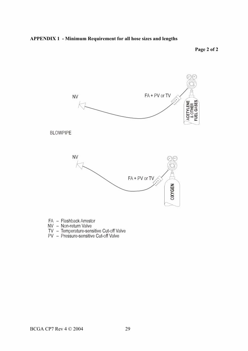
APPENDIX 1 - Minimum Requirement for all hose sizes and lengths
Page 2 of 2
BCGA CP7 Rev 4 © 2004 29

HISTORY AND OBJECTIVES OF BCGA
The British Compressed Gases Association was established in August l971 as the successor to the British Acetylene Association, formed in l901. Its Members consist of producers, suppliers of gases equipment and container manufacturers and users operating in the compressed gas field. The main objective of the Association is the advancement of technology and safe practice in the manufacture, handling and use of all gases and the design and manufacture of all containers, apparatus, appliances, plant, etc. BCGA also provides advice and makes representations, insofar as these relate to particular problems of the compressed gases industry, on behalf of its Members to all regulatory bodies, including the UK Government, concerning legislation both existing and proposed. Policy is determined by a Council elected from Member Companies, with detailed technical studies being undertaken by a Technical Committee and its specialist Sub-Committees appointed for this purpose. Further details of the Association may be obtained from:
BRITISH COMPRESSED GASES ASSOCIATION
6 St. Mary’s Street, Wallingford, OX10 0EL Tel: 0044 (0)1491 825533 Fax: 0044 (0)1491 826689
Website: www.bcga.co.uk E-mail: [email protected]
BCGA CP7 Rev 4 © 2004 30

British Compressed Gases Association www.bcga.co.uk